
Related Manuals for Renesas H8S Family


Summary of Contents for Renesas H8S Family
- Page 1 REJ09B0403-0100 H8S/2472 H8S/2462 Group Group Hardware Manual Renesas 16-Bit Single-Chip Microcomputer H8S Family / H8S/2400 Series H8S/2472 R4F2472 H8S/2462 R4F2462 Rev.1.00 Revision Date: Mar. 12, 2008...
- Page 2 Rev. 1.00 Mar. 12, 2008 Page ii of xIviii...
- Page 3 Please be sure to implement safety measures to guard against the possibility of physical injury, and injury or damage caused by fire in the event of the failure of a Renesas product, such as safety design for hardware and software including but not limited to redundancy, fire control and malfunction prevention, appropriate treatment for aging degradation or any other applicable measures.
-
Page 4: General Precautions On Handling Of Product
General Precautions on Handling of Product 1. Treatment of NC Pins Note: Do not connect anything to the NC pins. The NC (not connected) pins are either not connected to any of the internal circuitry or are used as test pins or to reduce noise. If something is connected to the NC pins, the operation of the LSI is not guaranteed. - Page 5 Configuration of This Manual This manual comprises the following items: 1. General Precautions on Handling of Product 2. Configuration of This Manual 3. Preface 4. Contents 5. Overview 6. Description of Functional Modules • CPU and System-Control Modules • On-Chip Peripheral Modules The configuration of the functional description of each module differs according to the module.
-
Page 6: Preface
The H8S/2472 Group, H8S/2462 Group products are single-chip microcomputers made up of the high-speed H8S/2600 CPU employing Renesas Technology original architecture as its core, and the peripheral functions required to configure a system. The H8S/2600 CPU has an instruction set that is compatible with the H8/300 and H8/300H CPUs. - Page 7 Related Manuals: The latest versions of all related manuals are available from our web site. Please ensure you have the latest versions of all documents you require. http://www.renesas.com/ H8S/2472 Group, H8S/2462 Group manuals: Document Title Document No. H8S/2472 Group, H8S/2462 Group Hardware Manual...
- Page 8 Rev. 1.00 Mar. 12, 2008 Page viii of xIviii...
-
Page 9: Table Of Contents
Contents Section 1 Overview....................1 Overview..........................1 Block Diagram ........................3 Pin Description........................4 1.3.1 Pin Assignments ....................... 4 1.3.2 Pin Assignment in Each Operating Mode..............6 1.3.3 Pin Functions ......................13 Section 2 CPU......................23 Features..........................23 2.1.1 Differences between H8S/2600 CPU and H8S/2000 CPU ........24 2.1.2 Differences from H8/300 CPU ................ -
Page 10: Table Of Contents
2.7.6 Immediate#xx:8, #xx:16, or #xx:32..............53 2.7.7 Program-Counter Relative@(d:8, PC) or @(d:16, PC) ........53 2.7.8 Memory Indirect@@aa:8 ................... 54 2.7.9 Effective Address Calculation ................55 Processing States........................57 Usage Note........................... 59 2.9.1 Notes on Using the Bit Operation Instruction............59 Section 3 MCU Operating Modes ............... -
Page 11: Table Of Contents
Interrupt Sources........................86 5.4.1 External Interrupts ....................86 5.4.2 Internal Interrupts ....................87 Interrupt Exception Handling Vector Table................. 88 Interrupt Control Modes and Interrupt Operation ..............91 5.6.1 Interrupt Control Mode 0 ..................93 5.6.2 Interrupt Control Mode 1 ..................95 5.6.3 Interrupt Exception Handling Sequence .............. -
Page 12: Table Of Contents
Bus Arbitration ........................155 6.8.1 Overview ......................155 6.8.2 Operation ......................155 6.8.3 Bus Mastership Transfer Timing ................156 Section 7 Data Transfer Controller (DTC)............159 Features..........................159 Register Descriptions......................161 7.2.1 DTC Mode Register A (MRA) ................162 7.2.2 DTC Mode Register B (MRB)................ -
Page 13: Table Of Contents
7.9.2 On-Chip RAM ...................... 186 7.9.3 DTCE Bit Setting....................186 7.9.4 DTC Activation by Interrupt Sources of SCI, IIC, or A/D Converter ....186 Section 8 I/O Ports .....................187 I/O Ports for the H8S/2472 Group ..................187 8.1.1 Port 1........................192 8.1.2 Port 2........................ -
Page 14: Table Of Contents
8.3.2 Port Control Register 0 (PTCNT0) ............... 356 Section 9 14-Bit PWM Timer (PWMX) ............357 Features..........................357 Input/Output Pins....................... 358 Register Descriptions......................358 9.3.1 PWMX (D/A) Counter (DACNT) ................ 359 9.3.2 PWMX (D/A) Data Registers A and B (DADRA and DADRB) ......360 9.3.3 PWMX (D/A) Control Register (DACR) ............. -
Page 15: Table Of Contents
11.2.1 Timer Counter (TCNT)..................394 11.2.2 Time Constant Register A (TCORA)..............395 11.2.3 Time Constant Register B (TCORB) ..............395 11.2.4 Timer Control Register (TCR)................396 11.2.5 Timer Control/Status Register (TCSR)..............399 11.2.6 Timer Connection Register S (TCONRS)............. 403 11.3 Operation Timing....................... 404 11.3.1 TCNT Count Timing .................... -
Page 16: Table Of Contents
Section 13 Serial Communication Interface (SCI)..........429 13.1 Features..........................429 13.2 Input/Output Pins....................... 432 13.3 Register Descriptions......................432 13.3.1 Receive Shift Register (RSR) ................433 13.3.2 Receive Data Register (RDR)................433 13.3.3 Transmit Data Register (TDR)................433 13.3.4 Transmit Shift Register (TSR) ................433 13.3.5 Serial Mode Register (SMR) ................ -
Page 17: Table Of Contents
13.8 Interrupt Sources........................ 487 13.8.1 Interrupts in Normal Serial Communication Interface Mode ....... 487 13.8.2 Interrupts in Smart Card Interface Mode .............. 488 13.9 Usage Notes ........................489 13.9.1 Module Stop Mode Setting ................... 489 13.9.2 Break Detection and Processing ................489 13.9.3 Mark State and Break Sending................ -
Page 18: Table Of Contents
15.3.14 SCIF Control Register (SCIFCR) ................. 524 15.4 Operation ........................... 526 15.4.1 Baud Rate ......................526 15.4.2 Operation in Asynchronous Communication............527 15.4.3 Initialization of the SCIF ..................528 15.4.4 Data Transmission/Reception with Flow Control..........531 15.4.5 Data Transmission/Reception Through the LPC Interface ........537 15.5 Interrupt Sources........................ -
Page 19: Table Of Contents
17.3.7 SS Transmit Data Registers 0 to 3 (SSTDR0 to SSTDR3)........562 17.3.8 SS Receive Data Registers 0 to 3 (SSRDR0 to SSRDR3)........563 17.3.9 SS Shift Register (SSTRSR)................. 563 17.4 Operation ........................... 564 17.4.1 Transfer Clock ...................... 564 17.4.2 Relationship of Clock Phase, Polarity, and Data ..........564 17.4.3 Relationship between Data Input/Output Pins and Shift Register ...... -
Page 20: Table Of Contents
18.6 Usage Notes ........................651 Section 19 LPC Interface (LPC)................ 665 19.1 Features..........................665 19.2 Input/Output Pins....................... 668 19.3 Register Descriptions......................669 19.3.1 Host Interface Control Registers 0 and 1 (HICR0 and HICR1)......671 19.3.2 Host Interface Control Registers 2 and 3 (HICR2 and HICR3)......679 19.3.3 Host Interface Control Register 4 (HICR4) ............ -
Page 21: Table Of Contents
19.4.1 LPC interface Activation ..................733 19.4.2 LPC I/O Cycles..................... 733 19.4.3 SMIC Mode Transfer Flow................... 735 19.4.4 BT Mode Transfer Flow ..................738 19.4.5 Gate A20....................... 740 19.4.6 LPC Interface Shutdown Function (LPCPD)............743 19.4.7 LPC Interface Serialized Interrupt Operation (SERIRQ) ........747 19.4.8 LPC Interface Clock Start Request ............... -
Page 22: Table Of Contents
20.3.21 Manual PAUSE Frame Set Register (MPR) ............775 20.3.22 Automatic PAUSE Frame Retransmission Count Set Register (TPAUSER) ..775 20.4 Operation ........................... 776 20.4.1 Transmission......................776 20.4.2 Reception ......................779 20.4.3 RMII Frame Timing ..................... 780 20.4.4 Accessing MII Registers..................782 20.4.5 Magic Packet Detection .................. -
Page 23: Table Of Contents
21.3.1 Descriptor List and Data Buffers ................816 21.3.2 Transmission......................826 21.3.3 Reception ......................828 21.3.4 Multi-Buffer Frame Transmit/Receive Processing ..........830 Section 22 USB Function Module (USB)............833 22.1 Features..........................833 22.2 Input/Output Pins ....................... 834 22.3 Register Descriptions ......................835 22.3.1 Interrupt Flag Register 0 (IFR0) ................ -
Page 24: Table Of Contents
22.5.3 Suspend and Resume Operations................867 22.5.4 Control Transfer....................872 22.5.5 EP1 Bulk-Out Transfer (Dual FIFOs)..............878 22.5.6 EP2 Bulk-In Transfer (Dual FIFOs) ..............879 22.5.7 EP3 Interrupt-In Transfer..................881 22.6 Processing of USB Standard Commands and Class/Vendor Commands ......882 22.6.1 Processing of Commands Transmitted by Control Transfer......... -
Page 25: Table Of Contents
23.7 Usage Notes ........................911 23.7.1 Setting of Module Stop Mode................911 23.7.2 Permissible Signal Source Impedance ..............911 23.7.3 Influences on Absolute Accuracy ................. 912 23.7.4 Setting Range of Analog Power Supply and Other Pins ........912 23.7.5 Notes on Board Design ..................912 23.7.6 Notes on Noise Countermeasures ................. -
Page 26: Table Of Contents
26.3 Register Descriptions....................... 1022 26.3.1 Instruction Register (SDIR) ................1023 26.3.2 Bypass Register (SDBPR) .................. 1024 26.3.3 Boundary Scan Register (SDBSR) ..............1024 26.3.4 ID Code Register (SDIDR)................. 1042 26.4 Operation ......................... 1043 26.4.1 TAP Controller State Transitions................ 1043 26.4.2 JTAG Reset......................1044 26.5 Boundary Scan......................... -
Page 27: Table Of Contents
28.7 Module Stop Mode ......................1072 28.8 Usage Notes ........................1072 28.8.1 I/O Port Status..................... 1072 28.8.2 Current Consumption when Waiting for Oscillation Settling ......1072 28.8.3 DTC Module Stop Mode ..................1072 28.8.4 Notes on Subclock Usage ................... 1072 Section 29 List of Registers ................1073 29.1 Register Addresses (Address Order)................ - Page 28 Rev. 1.00 Mar. 12, 2008 Page xxviii of xIviii...
- Page 29 Figures Section 1 Overview Figure 1.1 Internal Block Diagram ....................3 Figure 1.2 Pin Assignments (H8S/2472 Group) ................4 Figure 1.3 Pin Assignments (H8S/2462 Group) ................5 Section 2 CPU Figure 2.1 Exception Vector Table (Normal Mode)..............27 Figure 2.2 Stack Structure in Normal Mode ................. 27 Figure 2.3 Exception Vector Table (Advanced Mode)..............
- Page 30 Section 6 Bus Controller (BSC) Figure 6.1 Block Diagram of Bus Controller................107 Figure 6.2 IOS Signal Output Timing ..................124 Figure 6.3 Access Sizes and Data Alignment Control (8-bit Access Space)......125 Figure 6.4 Access Sizes and Data Alignment Control (16-bit Access Space) ......126 Figure 6.5 Bus Timing for 8-Bit, 2-State Access Space .............
- Page 31 Figure 7.7 Memory Mapping in Block Transfer Mode............... 178 Figure 7.8 Chain Transfer Operation ..................179 Figure 7.9 DTC Operation Timing (Example in Normal Mode or Repeat Mode)...... 180 Figure 7.10 DTC Operation Timing (Example of Block Transfer Mode, with Block Size of 2) ....................181 Figure 7.11 DTC Operation Timing (Example of Chain Transfer) ..........
- Page 32 Figure 10.11 Conflict between OCR Write and Compare-Match (When Automatic Addition Function is Used) ............. 388 Section 11 8-Bit Timer (TMR) Figure 11.1 Block Diagram of 8-Bit Timer (TMR_0 and TMR_1)..........392 Figure 11.2 Block Diagram of 8-Bit Timer (TMR_Y and TMR_X).......... 393 Figure 11.3 Count Timing for Internal Clock Input ..............
- Page 33 Figure 13.12 Example of SCI Operation in Reception (Example with 8-Bit Data, Multiprocessor Bit, One Stop Bit) ......463 Figure 13.13 Sample Multiprocessor Serial Reception Flowchart (1)........464 Figure 13.13 Sample Multiprocessor Serial Reception Flowchart (2)........465 Figure 13.14 Data Format in Synchronous Communication (LSB-First)........466 Figure 13.15 Sample SCI Initialization Flowchart ..............
- Page 34 Section 15 Serial Communication Interface with FIFO (SCIF) Figure 15.1 Block Diagram of SCIF................... 506 Figure 15.2 Data Format in Serial Transmission/Reception (Example with 8-Bit Data, Parity and 2 Stop Bits) ..........527 Figure 15.3 Example of Initialization Flowchart................ 528 Figure 15.4 Example of Data Transmission Flowchart ..............
- Page 35 Figure 17.17 Flowchart Example of Simultaneous Transmission/Reception (Clock Synchronous Communication Mode) ............582 Section 18 I C Bus Interface (IIC) Figure 18.1 Block Diagram of I C Bus Interface................ 586 Figure 18.2 I C Bus Interface Connections (Example: This LSI as Master) ......587 Figure 18.3 I C Bus Data Formats (I C Bus Formats)..............
- Page 36 Figure 18.29 Notes on Reading Master Receive Data ..............656 Figure 18.30 Flowchart for Start Condition Issuance Instruction for Retransmission and Timing ................657 Figure 18.31 Stop Condition Issuance Timing ................658 Figure 18.32 IRIC Flag Clearing Timing When WAIT = 1 ............659 Figure 18.33 ICDR Register Read and ICCR Register Access Timing in Slave Transmit Mode ....................
- Page 37 Figure 21.4 Sample Transmission Flowchart ................827 Figure 21.5 Sample Reception Flowchart................... 829 Figure 21.6 E-DMAC Operation after Transmit Error ............... 830 Figure 21.7 E-DMAC Operation after Receive Error..............831 Section 22 Ethernet Controller (EtherC) Figure 22.1 Block Diagram of USB ................... 834 Figure 22.2 Operation at Cable Connection ................
- Page 38 Figure 23.9 Example of Analog Input Protection Circuit............913 Figure 23.10 Analog Input Pin Equivalent Circuit ..............914 Section 25 Flash Memory Figure 25.1 Block Diagram of Flash Memory................918 Figure 25.2 Mode Transition of Flash Memory................919 Figure 25.3 Flash Memory Configuration .................. 921 Figure 25.4 Block Division of User MAT..................
- Page 39 Figure 27.5 Note on Board Design of Oscillation Circuit Section..........1056 Section 28 Power-Down Modes Figure 28.1 Mode Transition Diagram ..................1065 Figure 28.2 Medium-Speed Mode Timing ................1068 Figure 28.3 Software Standby Mode Application Example ............. 1070 Figure 28.4 Hardware Standby Mode Timing ................1071 Section 31 Electrical Characteristics Figure 31.1 Darlington Transistor Drive Circuit (Example).............
- Page 40 Figure 31.33 LPC Interface (LPC) Timing................1154 Figure 31.34 Timing of RM_REF-CLK and RMII Signals............1155 Figure 31.35 RMII Transmit Timing..................1156 Figure 31.36 RMII Receive Timing (Normal Operation)............1156 Figure 31.37 RMII Receive Timing (When an Error is Detected) ........... 1156 Figure 31.38 MDIO Input Timing ....................
- Page 41 Tables Section 1 Overview Table 1.1 Pin Assignments in Each Operating Mode ............... 6 Table 1.2 Pin Functions ......................13 Section 2 CPU Table 2.1 Instruction Classification ..................39 Table 2.2 Operation Notation ....................40 Table 2.3 Data Transfer Instructions..................41 Table 2.4 Arithmetic Operations Instructions (1) ..............
- Page 42 Table 5.9 Interrupt Source Selection and Clearing Control ..........101 Section 6 Bus Controller (BSC) Table 6.1 Pin Configuration....................108 Table 6.2 Address Ranges and External Address Spaces ............. 117 Table 6.3 Bit Settings and Bus Specifications of Basic Bus Interface........118 Table 6.4 Bus Specifications for Basic Extended Area/Basic Bus Interface ......
- Page 43 Table 8.8 Port D Input Pull-Up MOS States................. 261 Table 8.9 Port Functions ....................... 271 Table 8.10 Port 1 Input Pull-Up MOS States................277 Table 8.11 Port 2 Input Pull-Up MOS States................282 Table 8.12 Port 3 Input Pull-Up MOS States................288 Table 8.13 Port 4 Input Pull-Up MOS States................
- Page 44 Table 13.9 Maximum Bit Rate for Each Frequency (Smart Card Interface Mode, S = 372) ..............448 Table 13.10 Serial Transfer Formats (Asynchronous Mode)..........450 Table 13.11 SSR Status Flags and Receive Data Handling ..........457 Table 13.12 SCI Interrupt Sources..................487 Table 13.13 SCI Interrupt Sources..................
- Page 45 Table 18.13 C Bus Timing (with Maximum Influence of t )........654 Section 19 LPC Interface (LPC) Table 19.1 Pin Configuration....................668 Table 19.2 LADR1, LADR2 Initial Values ................684 Table 19.3 Host Register Selection..................685 Table 19.4 Slave Selection Internal Registers................. 685 Table 19.5 LPC I/O Cycle ......................
- Page 46 Table 25.4 Parameters and Target Modes................937 Table 25.5 Setting On-Board Programming Mode ..............947 Table 25.6 System Clock Frequency for Automatic-Bit-Rate Adjustment by This LSI..949 Table 25.7 Enumeration Information..................953 Table 25.8 Executable MAT....................973 Table 25.9 (1) Useable Area for Programming in User Program Mode.......
- Page 47 Table 31.8 Bus Timing ......................1134 Table 31.9 Multiplex Bus Timing..................1143 Table 31.10 Timing of On-Chip Peripheral Modules ............1146 Table 31.11 Timing of On-Chip Peripheral Modules (2)............ 1147 Table 31.12 C Bus Timing ....................1152 Table 31.13 LPC Module Timing ..................1153 Table 31.14 Ethernet Controller Signal Timing..............
- Page 48 Rev. 1.00 Mar. 12, 2008 Page xlviii of xIviii...
-
Page 49: Overview
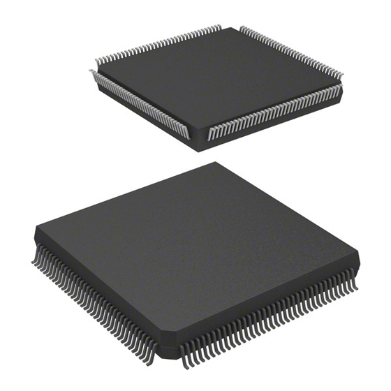
Section 1 Overview Section 1 Overview Overview • High-speed H8S/2600 central processing unit with an internal 16-bit architecture Upward-compatible with H8/300 and H8/300H CPUs on an object level Sixteen 16-bit general registers 69 basic instructions Multiplication and accumulation instructions • Various peripheral functions Data transfer controller (DTC) 14-bit PWM timer (PWMX) 16-bit free-running timer (FRT) - Page 50 Section 1 Overview • Reprogramming count: 1000 times (Tpy.) • General I/O ports I/O pins: 110 (for 176-pin), 106 (for 144-pin) Input-only pins: 9 • Supports various power-down states • Compact package Package (code) Body Size Pin Pitch PLBG0176GA-A 13 × 13 mm 0.8 mm PLQP0144KA-A 20 ×...
-
Page 51: Block Diagram
Section 1 Overview Block Diagram Clock pulse H8S/2600 (Flash) generator 512K (+16K UB) EtherC E-DMAC WDT × 2 14-bit PWM × 4 A/D converter SCI_1, SCI_3 8-bit timer × 4 (only in the H8S/2472) IIC_0 to IIC_5 PECI [Legend] CPU: Central processing unit DTC: Data transfer controller... -
Page 52: Pin Description
Section 1 Overview Pin Description 1.3.1 Pin Assignments AVSS AVCC AVref DrVCC USD+ USD- DrVSS VBUS PUPDPLS H8S/2472 Group PLBG0176GA-A ETMS ETDO ETCK ETDI BP-176V (Top view) ETRST STBY UXSEL PEVref PECI RESO EXTAL UEXTAL XTAL UXTAL : NC pin Figure 1.2 Pin Assignments (H8S/2472 Group) Rev. - Page 53 Section 1 Overview 99 98 97 96 95 94 93 92 91 90 89 88 87 86 85 84 83 82 81 80 79 78 77 76 75 74 73 108 107 106 105 104 103 102 101 100 P74/AN4 P11/A1/AD1 P73/AN3 P72/AN2...
-
Page 54: Pin Assignment In Each Operating Mode
Section 1 Overview 1.3.2 Pin Assignment in Each Operating Mode Table 1.1 Pin Assignments in Each Operating Mode Pin No. Pin Name Flash Memory 176- 144- Extended Mode Single-Chip Mode Programmer (EXPE = 1) (EXPE = 0) Mode A01 1 C03 2 P45/IRQ5/RS5/DB5/HC5/A13/AD13 P45/IRQ5/RS5/DB5/HC5... - Page 55 Section 1 Overview Pin No. Pin Name Flash Memory Programmer 176- 144- Extended Mode Single-Chip Mode (EXPE = 1) (EXPE = 0) Mode J03 24 P90/LBE J01 J02 25 K04 26 PC6/LWR K03 27 PC5/SDA4 PC5/SDA4 K01 28 PC4/SCL4 PC4/SCL4 K02 29 PC3/SDA3...
- Page 56 Section 1 Overview Pin No. Pin Name Flash Memory Programmer 176- 144- Extended Mode Single-Chip Mode (EXPE = 1) (EXPE = 0) Mode N05 43 P87/ExIRQ15/TxD3/ADTRG P87/ExIRQ15/TxD3/ADTRG P05 44 P86/ExIRQ14/RxD3 P86/ExIRQ14/RxD3 R05 45 P85/ExIRQ13/SCK1 P85/ExIRQ13/SCK1 M06 46 P84/ExIRQ12/SCK3 P84/ExIRQ12/SCK3 N06 47 P83/SDA1 P83/SDA1 R06 48...
- Page 57 Section 1 Overview Pin No. Pin Name Flash Memory Programmer 176- 144- Extended Mode Single-Chip Mode (EXPE = 1) (EXPE = 0) Mode P12 67 AVSS AVSS N12 68 P70/AN0 P70/AN0 R13 69 P71/AN1 P71/AN1 M12 70 P72/AN2 P72/AN2 P13 71 P73/AN3 P73/AN3 R14 72...
-
Page 58: Manual
Section 1 Overview Pin No. Pin Name Flash Memory Programmer 176- 144- Extended Mode Single-Chip Mode (EXPE = 1) (EXPE = 0) Mode H13 88 ETDO ETDO H15 89 ETDI ETDI H14 90 ETCK ETCK ETRST ETRST G12 91 G13 PF2/RS10 PF2/RS10 G15 92... - Page 59 Section 1 Overview Pin No. Pin Name Flash Memory Programmer 176- 144- Extended Mode Single-Chip Mode (EXPE = 1) (EXPE = 0) Mode A13 114 PB5/EVENT13/RM_REF-CLK PB5/EVENT13/RM_REF-CLK B12 115 PB4/EVENT12/RM_TX-EN PB4/EVENT12/RM_TX-EN D11 116 PB3/EVENT11/DB3/RM_RXD1 PB3/EVENT11/DB3/RM_RXD1 A12 117 PB2/EVENT10/DB2/RM_RXD0 PB2/EVENT10/DB2/RM_RXD0 C11 118 PB1/EVENT9/DB1/RM_TXD1 PB1/EVENT9/DB1/RM_TXD1 B11 119 PB0/EVENT8/DB0/RM_TXD0 PB0/EVENT8/DB0/RM_TXD0...
- Page 60 Section 1 Overview Pin No. Pin Name Flash Memory Programmer 176- 144- Extended Mode Single-Chip Mode (EXPE = 1) (EXPE = 0) Mode A05 UXTAL UXTAL B05 UEXTAL UEXTAL D05 UXSEL UXSEL A04 PF5/RS13 PF5/RS13 B04 PF4/RS12 PF4/RS12 C04 ...
-
Page 61: Pin Functions
Section 1 Overview 1.3.3 Pin Functions Table 1.2 Pin Functions Pin No. Type Symbol 176-Pin 144-Pin Name and Function Power A1, N2, 1, 36, 86, Input Power supply pins. Connect all these pins supply P9, K12, to the system power supply. Connect the A11, C5 bypass capacitor between VCC and VSS (near VCC). - Page 62 Section 1 Overview Pin No. Type Symbol 176-Pin 144-Pin Name and Function Address bus A23 to A16 M3, N1, 33 to 35, Output Address output pins M4, P1, 37 to 41 P2, N3, P3, R3 A15 to A0 C2, B1, 4 to 2, C3, B6, 140,...
- Page 63 Section 1 Overview Pin No. Type Symbol 176-Pin 144-Pin Name and Function Interrupts Input Nonmaskable interrupt request input pin IRQ15 to N15, 79, 78, Input These pins are used to request maskable IRQ0 M13, A6, 139, 138, interrupts. C6, B7, 136, 135, Either IRQn or ExIRQn can be selected D6, F2,...
- Page 64 Section 1 Overview Pin No. Type Symbol 176-Pin 144-Pin Name and Function Bus control Output Low level on this pin indicates that the MCU is writing to an external address space. Output Low level on this pin indicates that the MCU is accessing an external address space.
- Page 65 Section 1 Overview Pin No. Type Symbol 176-Pin 144-Pin Name and Function Synchronous SSCK Input/ SSU clock I/O pin serial Output communi- Input/ SSU data I/O pin cation unit Output (SSU) Input/ SSU data I/O pin Output SSU chip select I/O pin Input/ Output C bus...
- Page 66 Section 1 Overview Pin No. Type Symbol 176-Pin 144-Pin Name and Function LAD3 to LAD0 P8, M9, 55 to 58 Input/ Transfer cycle type/address/data I/O pins Interface N9, R9 Output (LPC) LFRAME Input Input pin indicating transfer cycle start and forced termination LRESET Input LPC reset pin.
- Page 67 Section 1 Overview Pin No. Type Symbol 176-Pin 144-Pin Name and Function USB function VBUS Input USB cable connection monitor pin module USB data I/O pin USD+ Input/ (USB) Output USD− Input/ USB data I/O pin Output ...
- Page 68 Section 1 Overview Pin No. Type Symbol 176-Pin 144-Pin Name and Function I/O ports P17 to P10 D13, 103 to Input/ 8-bit input/output pins C15, 109, 111 Output D12, C14, B15, B14, A15 P27 to P20 F15, F14, 95 to 102 Input/ 8-bit input/output pins E13, E15, Output...
- Page 69 Section 1 Overview Pin No. Type Symbol 176-Pin 144-Pin Name and Function I/O ports PA7 to PA0 M3, N1, 33 to 35, Input/ 8-bit input/output pins M4, P1, 37 to 41 Output P2, N3, P3, R3 PB7 to PB0 B13, C12, 112 to Input/ 8-bit input/output pins...
- Page 70 Section 1 Overview Rev. 1.00 Mar. 12, 2008 Page 22 of 1178 REJ09B0403-0100...
-
Page 71: Features
Section 2 CPU Section 2 CPU The H8S/2600 CPU is a high-speed central processing unit with an internal 32-bit architecture that is upward-compatible with the H8/300 and H8/300H CPUs. The H8S/2600 CPU has sixteen 16-bit general registers, can address a 16-Mbyte linear address space, and is ideal for realtime control. This section describes the H8S/2600 CPU. -
Page 72: Differences Between H8S/2600 Cpu And H8S/2000 Cpu
Section 2 CPU 16 ÷ 8-bit register-register divide: 12 states 16 × 16-bit register-register multiply: 3 states 32 ÷ 16-bit register-register divide: 20 states • Two CPU operating modes Normal mode* Advanced mode • Power-down state ... -
Page 73: Differences From H8/300 Cpu
Section 2 CPU 2.1.2 Differences from H8/300 CPU In comparison to the H8/300 CPU, the H8S/2600 CPU has the following enhancements: • More general registers and control registers Eight 16-bit extended registers, and one 8-bit and two 32-bit control registers, have been added. -
Page 74: Cpu Operating Modes
Section 2 CPU CPU Operating Modes The H8S/2600 CPU has two operating modes: normal and advanced. Normal mode supports a maximum 64-kbyte address space. Advanced mode supports a maximum 16-Mbyte total address space. The mode is selected by the mode pins. 2.2.1 Normal Mode The exception vector table and stack have the same structure as in the H8/300 CPU. - Page 75 Section 2 CPU H'0000 Exception vector 1 H'0001 H'0002 Exception vector 2 H'0003 H'0004 Exception vector 3 H'0005 Exception H'0006 Exception vector 4 vector table H'0007 H'0008 Exception vector 5 H'0009 H'000A Exception vector 6 H'000B Figure 2.1 Exception Vector Table (Normal Mode) EXR* (16 bits) Reserved*...
-
Page 76: Advanced Mode
Section 2 CPU 2.2.2 Advanced Mode • Address Space Linear access to a 16-Mbyte maximum address space is provided. • Extended Registers (En) The extended registers (E0 to E7) can be used as 16-bit registers, or as the upper 16-bit segments of 32-bit registers or address registers. - Page 77 Section 2 CPU The memory indirect addressing mode (@@aa:8) employed in the JMP and JSR instructions uses an 8-bit absolute address included in the instruction code to specify a memory operand that contains a branch address. In advanced mode the operand is a 32-bit longword operand, providing a 32-bit branch address.
-
Page 78: Address Space
Section 2 CPU Address Space Figure 2.5 shows a memory map for the H8S/2600 CPU. The H8S/2600 CPU provides linear access to a maximum 64-kbyte address space in normal mode, and a maximum 16-Mbyte (architecturally 4-Gbyte) address space in advanced mode. The usable modes and address spaces differ depending on the product. -
Page 79: Registers
Section 2 CPU Registers The H8S/2600 CPU has the internal registers shown in figure 2.6. There are two types of registers; general registers and control registers. The control registers are a 24-bit program counter (PC), an 8-bit extended control register (EXR), an 8-bit condition code register (CCR), and a 64-bit multiply-accumulate register (MAC). -
Page 80: General Registers
Section 2 CPU 2.4.1 General Registers The H8S/2600 CPU has eight 32-bit general registers. These general registers are all functionally identical and can be used as both address registers and data registers. When a general register is used as a data register, it can be accessed as a 32-bit, 16-bit, or 8-bit register. Figure 2.7 illustrates the usage of the general registers. -
Page 81: Program Counter (Pc)
Section 2 CPU Free area SP (ER7) Stack area Figure 2.8 Stack 2.4.2 Program Counter (PC) This 24-bit counter indicates the address of the next instruction the CPU will execute. The length of all CPU instructions is 2 bytes (one word), so the least significant PC bit is ignored. (When an instruction is fetched, the least significant PC bit is regarded as 0). -
Page 82: Condition-Code Register (Ccr)
Section 2 CPU 2.4.4 Condition-Code Register (CCR) This 8-bit register contains internal CPU status information, including an interrupt mask bit (I) and half-carry (H), negative (N), zero (Z), overflow (V), and carry (C) flags. Operations can be performed on the CCR bits by the LDC, STC, ANDC, ORC, and XORC instructions. -
Page 83: Multiply-Accumulate Register (Mac)
Section 2 CPU Initial Value Bit Name Description Undefined R/W Overflow Flag Set to 1 when an arithmetic overflow occurs, and cleared to 0 at other times. Undefined R/W Carry Flag Set to 1 when a carry occurs, and cleared to 0 otherwise. -
Page 84: Data Formats
Section 2 CPU Data Formats The H8S/2600 CPU can process 1-bit, 4-bit (BCD), 8-bit (byte), 16-bit (word), and 32-bit (longword) data. Bit-manipulation instructions operate on 1-bit data by accessing bit n (n = 0, 1, 2, …, 7) of byte operand data. The DAA and DAS decimal-adjust instructions treat byte data as two digits of 4-bit BCD data. - Page 85 Section 2 CPU Data Type Register Number Data Format Word data Word data Longword data [Legend] ERn: General register ER General register E General register R RnH: General register RH RnL: General register RL MSB: Most significant bit LSB: Least significant bit Figure 2.9 General Register Data Formats (2) Rev.
-
Page 86: Memory Data Formats
Section 2 CPU 2.5.2 Memory Data Formats Figure 2.10 shows the data formats in memory. The H8S/2600 CPU can access word data and longword data in memory, however word or longword data must begin at an even address. If an attempt is made to access word or longword data at an odd address, an address error does not occur, however the least significant bit of the address is regarded as 0, so access begins the preceding address. -
Page 87: Instruction Set
Section 2 CPU Instruction Set The H8S/2600 CPU has 69 instructions. The instructions are classified by function in table 2.1. Table 2.1 Instruction Classification Function Instructions Size Types Data transfer B/W/L 5 POP* , PUSH* LDM, STM MOVFPE* , MOVTPE* Arithmetic ADD, SUB, CMP, NEG B/W/L 23... -
Page 88: Table Of Instructions Classified By Function
Section 2 CPU 2.6.1 Table of Instructions Classified by Function Tables 2.3 to 2.10 summarize the instructions in each functional category. The notation used in tables 2.3 to 2.10 is defined below. Table 2.2 Operation Notation Symbol Description General register (destination)* General register (source)* General register* General register (32-bit register) - Page 89 Section 2 CPU Table 2.3 Data Transfer Instructions Instruction Size* Function (EAs) → Rd, Rs → (EAd) B/W/L Moves data between two general registers or between a general register and memory, or moves immediate data to a general register. MOVFPE Cannot be used in this LSI.
- Page 90 Section 2 CPU Table 2.4 Arithmetic Operations Instructions (1) Instruction Size* Function Rd ± Rs → Rd, Rd ± #IMM → Rd B/W/L Performs addition or subtraction on data in two general registers, or on immediate data and data in a general register (immediate byte data cannot be subtracted from byte data in a general register.
- Page 91 Section 2 CPU Table 2.4 Arithmetic Operations Instructions (2) Instruction Size* Function Rd ÷ Rs → Rd DIVXS Performs signed division on data in two general registers: either 16 bits ÷ 8 bits → 8-bit quotient and 8-bit remainder or 32 bits ÷ 16 bits → 16-bit quotient and 16-bit remainder.
- Page 92 Section 2 CPU Table 2.5 Logic Operations Instructions Instruction Size* Function Rd ∧ Rs → Rd, Rd ∧ #IMM → Rd B/W/L Performs a logical AND operation on a general register and another general register or immediate data. Rd ∨ Rs → Rd, Rd ∨ #IMM → Rd B/W/L Performs a logical OR operation on a general register and another general register or immediate data.
- Page 93 Section 2 CPU Table 2.7 Bit Manipulation Instructions (1) Instruction Size* Function 1 → (<bit-No.> of <EAd>) BSET Sets a specified bit in a general register or memory operand to 1. The bit number is specified by 3-bit immediate data or the lower three bits of a general register.
- Page 94 Section 2 CPU Table 2.7 Bit Manipulation Instructions (2) Instruction Size* Function C ⊕ (<bit-No.> of <EAd>) → C BXOR XORs the carry flag with a specified bit in a general register or memory operand and stores the result in the carry flag. ∼...
- Page 95 Section 2 CPU Table 2.8 Branch Instructions Instruction Size Function Branches to a specified address if a specified condition is true. The branching conditions are listed below. Mnemonic Description Condition BRA(BT) Always (true) Always BRN(BF) Never (false) Never C ∨ Z = 0 High C ∨...
- Page 96 Section 2 CPU Table 2.9 System Control Instructions Instruction Size* Function TRAPA Starts trap-instruction exception handling. Returns from an exception-handling routine. SLEEP Causes a transition to a power-down state. (EAs) → CCR, (EAs) → EXR Moves general register or memory contents or immediate data to CCR or EXR.
- Page 97 Section 2 CPU Table 2.10 Block Data Transfer Instructions Instruction Size Function if R4L ≠ 0 then EEPMOV.B Repeat @ER5+ → @ER6+ R4L–1 → R4L Until R4L = 0 else next; if R4 ≠ 0 then EEPMOV.W Repeat @ER5+ → @ER6+ R4–1 →...
-
Page 98: Basic Instruction Formats
Section 2 CPU 2.6.2 Basic Instruction Formats The H8S/2600 CPU instructions consist of 2-byte (1-word) units. An instruction consists of an operation field (op field), a register field (r field), an effective address extension (EA field), and a condition field (cc). Figure 2.11 shows examples of instruction formats. -
Page 99: Addressing Modes And Effective Address Calculation
Section 2 CPU Addressing Modes and Effective Address Calculation The H8S/2600 CPU supports the eight addressing modes listed in table 2.11. Each instruction uses a subset of these addressing modes. Arithmetic and logic instructions can use the register direct and immediate modes. Data transfer instructions can use all addressing modes except program- counter relative and memory indirect. -
Page 100: Register Indirect With Displacement@(D:16, Ern) Or @(D:32, Ern)
Section 2 CPU 2.7.3 Register Indirect with Displacement@(d:16, ERn) or @(d:32, ERn) A 16-bit or 32-bit displacement contained in the instruction is added to an address register (ERn) specified by the register field of the instruction, and the sum gives the address of a memory operand. -
Page 101: Immediate#Xx:8, #Xx:16, Or #Xx:32
Section 2 CPU Table 2.12 Absolute Address Access Ranges Absolute Address Normal Mode* Advanced Mode Data address 8 bits (@aa:8) H'FF00 to H'FFFF H'FFFF00 to H'FFFFFF 16 bits (@aa:16) H'0000 to H'FFFF H'000000 to H'007FFF, H'FF8000 to H'FFFFFF 32 bits (@aa:32) H'000000 to H'FFFFFF Program instruction 24 bits (@aa:24) -
Page 102: Memory Indirect@@Aa:8
Section 2 CPU 2.7.8 Memory Indirect@@aa:8 This mode can be used by the JMP and JSR instructions. The instruction code contains an 8-bit absolute address specifying a memory operand. This memory operand contains a branch address. The upper bits of the absolute address are all assumed to be 0, so the address range is 0 to 255 (H'0000 to H'00FF in normal mode, H'000000 to H'0000FF in advanced mode). -
Page 103: Effective Address Calculation
Section 2 CPU 2.7.9 Effective Address Calculation Table 2.13 indicates how effective addresses are calculated in each addressing mode. In normal mode the upper 8 bits of the effective address are ignored in order to generate a 16-bit address. Note: Normal mode is not available in this LSI. Table 2.13 Effective Address Calculation (1) Addressing Mode and Instruction Format Effective Address Calculation... - Page 104 Section 2 CPU Table 2.13 Effective Address Calculation (2) Addressing Mode and Instruction Format Effective Address Calculation Effective Address (EA) Absolute address Sign extension Immediate Operand is immediate data. PC contents Sign extension Memory contents Memory contents Note: * Normal mode is not available in this LSI. Rev.
-
Page 105: Processing States
Section 2 CPU Processing States The H8S/2600 CPU has four main processing states: the reset state, exception handling state, program execution state and power-down state. Figure 2.13 indicates the state transitions. • Reset State In this state, the CPU and all on-chip peripheral modules are initialized and not operating. When the RES input goes low, all current processing stops and the CPU enters the reset state. - Page 106 Section 2 CPU End of bus request Bus request Program execution state SLEEP End of bus instruction request with SLEEP SSBY = 0 instruction request with PSS = 0 and SSBY = 1 Bus-released state Request for End of exception exception handling Sleep mode...
-
Page 107: Usage Note
Section 2 CPU Usage Note 2.9.1 Notes on Using the Bit Operation Instruction Instructions BSET, BCLR, BNOT, BST, and BIST read data in byte units, and write data in byte units after bit operation. Therefore, attention must be paid when these instructions are used for ports or registers including write-only bits. - Page 108 Section 2 CPU Rev. 1.00 Mar. 12, 2008 Page 60 of 1178 REJ09B0403-0100...
-
Page 109: Section 3 Mcu Operating Modes
Section 3 MCU Operating Modes Section 3 MCU Operating Modes Operating Mode Selection This LSI supports one operating mode (mode 2). The operating mode is determined by the setting of the mode pins (MD2 and MD1). Table 3.1 shows the MCU operating mode selection. Table 3.1 MCU Operating Mode Selection MCU Operating... -
Page 110: Register Descriptions
Section 3 MCU Operating Modes Register Descriptions The following registers are related to the operating mode. For details on the bus control register (BCR), see section 6.3.1, Bus Control Register (BCR), and for details on bus control register 2 (BCR2), see section 6.3.2, Bus Control Register 2 (BCR2). •... -
Page 111: System Control Register (Syscr)
Section 3 MCU Operating Modes 3.2.2 System Control Register (SYSCR) SYSCR selects a system pin function, monitors a reset source, selects the interrupt control mode and the detection edge for NMI, enables or disables register access to the on-chip peripheral modules, and enables or disables on-chip RAM address space. -
Page 112: Serial Timer Control Register (Stcr)
Section 3 MCU Operating Modes Initial Value Bit Name Description XRST External Reset This bit indicates the reset source. A reset is caused by an external reset input, or when the watchdog timer overflows. 0: A reset is caused when the watchdog timer overflows. - Page 113 Section 3 MCU Operating Modes Initial Value Bit Name Description Reserved The initial value should not be changed. FLSHE Flash Memory Control Register Enable Enables or disables CPU access for flash memory registers (FCCS, FPCS, FECS, FKEY, FMATS, FTDAR), control registers of power-down states (SBYCR, LPWRCR, MSTPCRH, MSTPCRL), and control registers of on-chip peripheral modules (BCR2, WSCR2, PCSR,...
-
Page 114: Operating Mode Descriptions
Section 3 MCU Operating Modes Operating Mode Descriptions 3.3.1 Mode 2 The CPU can access a 16 Mbytes address space in advanced mode. The on-chip ROM is enabled. After a reset, the LSI is set to single-chip mode. To access an external address space, bit EXPE in MDCR should be set to 1. -
Page 115: Address Map
Section 3 MCU Operating Modes Address Map Figure 3.1 shows the memory map in operating modes. ROM: 512 Kbytes, RAM: 40 Kbytes ROM: 512 Kbytes, RAM: 40 Kbytes Mode 2 (EXPE = 1) Mode 2 (EXPE = 0) Advanced mode Advanced mode Extended mode with Single-chip mode... - Page 116 Section 3 MCU Operating Modes Rev. 1.00 Mar. 12, 2008 Page 68 of 1178 REJ09B0403-0100...
-
Page 117: Section 4 Exception Handling
Section 4 Exception Handling Section 4 Exception Handling Exception Handling Types and Priority As table 4.1 indicates, exception handling may be caused by a reset, interrupt, illegal instruction, or trap instruction. Exception handling is prioritized as shown in table 4.1. If two or more exceptions occur simultaneously, they are accepted and processed in order of priority. -
Page 118: Exception Sources And Exception Vector Table
Section 4 Exception Handling Exception Sources and Exception Vector Table Different vector addresses are assigned to different exception sources. Table 4.2 lists the exception sources and their vector addresses. Table 4.2 Exception Handling Vector Table Vector Address Exception Source Vector Number Advanced Mode Reset H'000000 to H'000003... - Page 119 Section 4 Exception Handling Vector Address Exception Source Vector Number Advanced Mode Reserved for system use H'000078 to H'00007B H'000084 to H'000087 Internal interrupt* H'000088 to H'00008B H'0000DC to H'0000DF External interrupt IRQ8 H'0000E0 to H'0000E3 IRQ9 H'0000E4 to H'0000E7 IRQ10...
-
Page 120: Reset
Section 4 Exception Handling Reset A reset has the highest exception priority. When the RES pin goes low, all processing halts and this LSI enters the reset. To ensure that this LSI is reset, hold the RES pin low for at least 20 ms at power-on. -
Page 121: Interrupts After Reset
Section 4 Exception Handling Vector Internal Prefetch of first fetch processing program instruction φ Internal address bus (1) U (1) L Internal read signal Internal write signal High Internal data bus (1) Reset exception handling vector address (1) U = H'000000 (1) L = H'000002 (2) Start address (contents of reset exception handling vector address) (3) Start address ((3) = (2)U + (2)L) (4) First program instruction... -
Page 122: Interrupt Exception Handling
Section 4 Exception Handling Interrupt Exception Handling Interrupts are controlled by the interrupt controller. The sources to start interrupt exception handling are external interrupt sources (NMI and IRQ15 to IRQ0) and internal interrupt sources from the on-chip peripheral modules. NMI is an interrupt with the highest priority. For details, see section 5, Interrupt Controller. -
Page 123: Stack Status After Exception Handling
Section 4 Exception Handling Stack Status after Exception Handling Figure 4.2 shows the stack after completion of trap instruction exception handling and interrupt exception handling. Advanced mode (24 bits) Figure 4.2 Stack Status after Exception Handling Rev. 1.00 Mar. 12, 2008 Page 75 of 1178 REJ09B0403-0100... - Page 124 Section 4 Exception Handling Usage Note When accessing word data or longword data, this LSI assumes that the lowest address bit is 0. The stack should always be accessed in words or longwords, and the value of the stack pointer (SP: ER7) should always be kept even.
-
Page 125: Section 5 Interrupt Controller
Section 5 Interrupt Controller Section 5 Interrupt Controller Features • Two interrupt control modes Any of two interrupt control modes can be set by means of the INTM1 and INTM0 bits in the system control register (SYSCR). • Priorities settable with ICR An interrupt control register (ICR) is provided for setting interrupt priorities. -
Page 126: Input/Output Pins
Section 5 Interrupt Controller INTM1, INTM0 SYSCR NMIEG NMI input NMI input Interrupt request IRQ input IRQ input Vector number Priority level ISCR determination I, UI Internal interrupt sources SWDTEND to EINT Interrupt controller [Legend] ICR: Interrupt control register ISCR: IRQ sense control register IER: IRQ enable register... - Page 127 Section 5 Interrupt Controller Register Descriptions The interrupt controller has the following registers. For details on the system control register (SYSCR), see section 3.2.2, System Control Register (SYSCR), and for details on the IRQ sense port select registers (ISSR16 and ISSR), see section 8.3.1, IRQ Sense Port Select Register 16 (ISSR16), IRQ Sense Port Select Register (ISSR).
-
Page 128: Address Break Control Register (Abrkcr)
Section 5 Interrupt Controller Table 5.2 Correspondence between Interrupt Source and ICR Register Bit Name ICRA ICRB ICRC ICRD ICRn7 IRQ0 A/D converter SCI_3 IRQ8 to IRQ11 ICRn6 IRQ1 SCI_1 IRQ12 to IRQ15 ICRn5 IRQ2, IRQ3 — EtherC ICRn4 IRQ4, IRQ5 TMR_X IIC_0 —... -
Page 129: Break Address Registers A To C (Bara To Barc)
Section 5 Interrupt Controller 5.3.3 Break Address Registers A to C (BARA to BARC) The BAR registers specify an address that is to be a break address. An address in which the first byte of an instruction exists should be set as a break address. •... -
Page 130: Irq Sense Control Registers (Iscr16H, Iscr16L, Iscrh, Iscrl)
Section 5 Interrupt Controller 5.3.4 IRQ Sense Control Registers (ISCR16H, ISCR16L, ISCRH, ISCRL) The ISCR registers select the source that generates an interrupt request at pins IRQ15 to IRQ0 or pins ExIRQ15 to ExIRQ0. • ISCR16H Initial Bit Name Value Description IRQ15SCB IRQn Sense Control B... - Page 131 Section 5 Interrupt Controller • ISCRH Initial Bit Name Value Description IRQ7SCB IRQn Sense Control B IRQn Sense Control A IRQ7SCA 00: Interrupt request generated at low level of IRQn or IRQ6SCB ExIRQn input IRQ6SCA 01: Interrupt request generated at falling edge of IRQn or ExIRQn input IRQ5SCB 10: Interrupt request generated at rising edge of IRQn or...
-
Page 132: Irq Enable Registers (Ier16, Ier)
Section 5 Interrupt Controller 5.3.5 IRQ Enable Registers (IER16, IER) The IER registers control the enabling and disabling of interrupt requests IRQ15 to IRQ0. • IER16 Initial Value Bit Name Description 7 to 0 IRQ15E to All 0 IRQn Enable (n = 15 to 8) IRQ8E The IRQn interrupt request is enabled when this bit is 1. -
Page 133: Irq Status Registers (Isr16, Isr)
Section 5 Interrupt Controller 5.3.6 IRQ Status Registers (ISR16, ISR) The ISR registers are flag registers that indicate the status of IRQ15 to IRQ0 interrupt requests. • ISR16 Initial Value Bit Name Description 7 to 0 IRQ15F to All 0 [Setting condition] IRQ8F •... -
Page 134: Interrupt Sources
Section 5 Interrupt Controller Interrupt Sources 5.4.1 External Interrupts There are four external interrupts: NMI, IRQ15 to IRQ0. These interrupts can be used to restore this LSI from software standby mode. NMI Interrupt: NMI is the highest-priority interrupt, and is always accepted by the CPU regardless of the interrupt control mode or the status of the CPU interrupt mask bits. -
Page 135: Internal Interrupts
Section 5 Interrupt Controller IRQnE IRQnSCA, IRQnSCB IRQnF IRQn interrupt Edge/level request detection circuit IRQn input or ExIRQn* input Clear signal n = 15 to 0 Figure 5.2 Block Diagram of Interrupts IRQ15 to IRQ0 5.4.2 Internal Interrupts Internal interrupts issued from the on-chip peripheral modules have the following features: •... -
Page 136: Interrupt Exception Handling Vector Table
Section 5 Interrupt Controller Interrupt Exception Handling Vector Table Table 5.3 lists interrupt exception handling sources, vector addresses, and interrupt priorities. For default priorities, the lower the vector number, the higher the priority. Modules set at the same priority will conform to their default priorities. Priorities within a module are fixed. An interrupt control level can be specified for a module to which an ICR bit is assigned. - Page 137 Section 5 Interrupt Controller Origin of Vector Address Interrupt Vector Source Name Number Advanced Mode Priority External pin IRQ8 ICRD7 High 0000E0 IRQ9 0000E4 IRQ10 0000E8 IRQ11 0000EC IRQ12 ICRD6 0000F0 IRQ13 0000F4 IRQ14 0000F8 IRQ15 0000FC TMR_0 CMIA0 (Compare match A) ICRB3 000100 CMIB0 (Compare match B)
- Page 138 Section 5 Interrupt Controller Origin of Vector Address Interrupt Vector Source Name Number Advanced Mode Priority High PECI PEWFCSEI 0001B0 ICRD2 PERFCSEI 0001B4 PETEI 0001B8 USB (only in RESUME H'0001C8 ICRC0 the H8S/2472) USBINT0 H'0001CC USBINT2 H'0001D0 USBINT3 H'0001D4 USBINT1 H'0001D8 EtherC EINT...
-
Page 139: Interrupt Control Modes And Interrupt Operation
Section 5 Interrupt Controller Interrupt Control Modes and Interrupt Operation The interrupt controller has two modes: Interrupt control mode 0 and interrupt control mode 1. Interrupt operations differ depending on the interrupt control mode. NMI interrupts and address break interrupts are always accepted except for in reset state or in hardware standby mode. The interrupt control mode is selected by SYSCR. - Page 140 Section 5 Interrupt Controller Interrupt Acceptance Control and 3-Level Control: In interrupt control modes 0 and 1, interrupt acceptance control and 3-level mask control is performed by means of the I and UI bits in CCR and ICR (control level). Table 5.5 shows the interrupts selected in each interrupt control mode.
-
Page 141: Interrupt Control Mode 0
Section 5 Interrupt Controller Table 5.6 Operations and Control Signal Functions in Each Interrupt Control Mode Interrupt Acceptance Control Setting 3-Level Control Interrupt Default Priority Control Mode INTM1 INTM0 Determination T (Trace) — — — [Legend] Interrupt operation control performed Used as an interrupt mask bit Sets priority —:... - Page 142 Section 5 Interrupt Controller 7. The CPU generates a vector address for the accepted interrupt and starts execution of the interrupt handling routine at the address indicated by the contents of the vector address in the vector table. Program execution state Interrupt generated? Pending An interrupt with interrupt...
-
Page 143: Interrupt Control Mode 1
Section 5 Interrupt Controller 5.6.2 Interrupt Control Mode 1 In interrupt control mode 1, mask control is applied to three levels for IRQ and on-chip peripheral module interrupt requests by comparing the I and UI bits in CCR in the CPU, and the ICR setting. •... - Page 144 Section 5 Interrupt Controller Figure 5.6 shows a flowchart of the interrupt acceptance operation. 1. If an interrupt source occurs when the corresponding interrupt enable bit is set to 1, an interrupt request is sent to the interrupt controller. 2. According to the interrupt control level specified in ICR, the interrupt controller only accepts an interrupt request with interrupt control level 1 (priority), and holds pending an interrupt request with interrupt control level 0 (no priority).
- Page 145 Section 5 Interrupt Controller Program execution state Interrupt generated? Pending An interrupt with interrupt control level 1? IRQ0 IRQ0 IRQ1 IRQ1 EINT EINT I = 0 I = 0 UI = 0 Save PC and CCR 1, UI Read vector address Branch to interrupt handling routine Figure 5.6 Flowchart of Procedure Up to Interrupt Acceptance in Interrupt Control Mode 1...
-
Page 146: Interrupt Exception Handling Sequence
Section 5 Interrupt Controller 5.6.3 Interrupt Exception Handling Sequence Figure 5.7 shows the interrupt exception handling sequence. The example shown is for the case where interrupt control mode 0 is set in advanced mode, and the program area and stack area are in on-chip memory. -
Page 147: Interrupt Response Times
Section 5 Interrupt Controller 5.6.4 Interrupt Response Times Table 5.7 shows interrupt response times − the intervals between generation of an interrupt request and execution of the first instruction in the interrupt handling routine. The execution status symbols used in table 5.7 are explained in table 5.8. Table 5.7 Interrupt Response Times Execution Status... -
Page 148: Dtc Activation By Interrupt
Section 5 Interrupt Controller 5.6.5 DTC Activation by Interrupt The DTC can be activated by an interrupt. In this case, the following options are available: • Interrupt request to CPU • Activation request to DTC • Both of the above For details of interrupt requests that can be used to activate the DTC, see section 7, Data Transfer Controller (DTC). - Page 149 Section 5 Interrupt Controller Determination of Priority The DTC activation source is selected in accordance with the default priority order, and is not affected by mask or priority levels. See section 7.5, Location of Register Information and DTC Vector Table, for the respective priorities. Operation Order If the same interrupt is selected as a DTC activation source and a CPU interrupt source, the DTC data transfer is performed first, followed by CPU interrupt exception handling.
-
Page 150: Usage Notes
Section 5 Interrupt Controller Usage Notes 5.7.1 Conflict between Interrupt Generation and Disabling When an interrupt enable bit is cleared to 0 to disable interrupt requests, the disabling becomes effective after execution of the instruction. When an interrupt enable bit is cleared to 0 by an instruction such as BCLR or MOV, and if an interrupt is generated during execution of the instruction, the interrupt concerned will still be enabled on completion of the instruction, so interrupt exception handling for that interrupt will be executed on completion of the instruction. -
Page 151: Instructions That Disable Interrupts
Section 5 Interrupt Controller 5.7.2 Instructions that Disable Interrupts The instructions that disable interrupts are LDC, ANDC, ORC, and XORC. After any of these instructions are executed, all interrupts including NMI are disabled and the next instruction is always executed. When the I bit or UI bit is set by one of these instructions, the new value becomes valid two states after execution of the instruction ends. - Page 152 Section 5 Interrupt Controller Rev. 1.00 Mar. 12, 2008 Page 104 of 1178 REJ09B0403-0100...
- Page 153 Section 6 Bus Controller (BSC) Section 6 Bus Controller (BSC) This LSI has an on-chip bus controller (BSC) that manages the bus width and the number of access states of the external address space. The BSC also has a bus arbitration function, and controls the operation of the internal bus masters –...
- Page 154 Section 6 Bus Controller (BSC) • Multiplex bus interface No Wait Inserted Wait Inserted Address Data Address Data 256-Kbyte 2 states* 2 states 2 states* (3 + wait) states extended area IOS extended area 2 states* 2 states 2 states* (3 + wait) states Note: * A wait cycle is inserted by the setting of the WC22 bit.
- Page 155 Section 6 Bus Controller (BSC) Internal control signals External bus control signals controller Bus mode signal BCR2 WSCR WSCR2 Wait WAIT controller CPU bus request signal DTC bus request signal Bus arbiter E-DMAC bus request signal CPU bus acknowledge signal DTC bus acknowledge signal E-DMAC bus acknowledge signal [Legend]...
- Page 156 Section 6 Bus Controller (BSC) Input/Output Pins Table 6.1 summarizes the pin configuration of the bus controller. Table 6.1 Pin Configuration Symbol Function Output Strobe signal indicating that address output on the address bus is enabled (when the IOSE bit in SYSCR is cleared to 0). Note that this signal is not output when the 256-Kbyte extended area is accessed (the CS256E bit in SYSCR is 1).
- Page 157 Section 6 Bus Controller (BSC) Register Descriptions The following registers are provided for the bus controller. For the system control register (SYSCR), see section 3.2.2, System Control Register (SYSCR). For port control register 0 (PTCNT0), see section 8.3.2, Port Control Register 0 (PTCNT0). •...
- Page 158 Section 6 Bus Controller (BSC) Initial Value Bit Name Description BRSTS1 Valid only in the normal extended mode. Burst Cycle Select 1 Selects the number of states in the burst cycle of the burst ROM interface. 0: 1 state 1: 2 states BRSTS0 Valid only in the normal extended mode.
-
Page 159: Bus Control Register 2 (Bcr2)
Section 6 Bus Controller (BSC) 6.3.2 Bus Control Register 2 (BCR2) BCR2 is used to specify the access mode for the extended area. Initial Bit Name Value Description 7, 6 All 0 Reserved The initial value should not be changed. ... -
Page 160: Wait State Control Register (Wscr)
Section 6 Bus Controller (BSC) 6.3.3 Wait State Control Register (WSCR) WSCR is used to specify the data bus width, the number of access states, the wait mode, and the number of wait states for access to external address spaces (basic extended area and 256-Kbyte extended area). - Page 161 Section 6 Bus Controller (BSC) Initial Value Bit Name Description Basic Extended Area Access State Control Selects the number of states for access to the basic extended area. This bit also enables or disables wait- state insertion. [ADMXE = 0] Normal extension 0: 2-state access space.
-
Page 162: Wait State Control Register 2 (Wscr2)
Section 6 Bus Controller (BSC) 6.3.4 Wait State Control Register 2 (WSCR2) WSCR2 is used to specify the wait mode and number of wait states in access to the 256-Kbyte extended area. Initial Bit Name Value Description WMS10 256-Kbyte Extended Area Wait Mode Select 0 Selects the wait mode for access to the 256-Kbyte extended area when the CS256E bit in SYSCR and the AST256 bit in WSCR are set to 1. -
Page 163: System Control Register 2 (Syscr2)
Section 6 Bus Controller (BSC) • When ADMXE = 0 Initial Bit Name Value Description 2 to 0 All 1 Reserved • When ADMXE = 1 Initial Bit Name Value Description WC22 Address-Data Multiplex Extended Area Address Cycle Wait Count 2 Selects the number of program wait states to be inserted into the address cycle for access to the address-data multiplex extended area. -
Page 164: Bus Control
Section 6 Bus Controller (BSC) Bus Control 6.4.1 Bus Specifications The external address space bus specifications consist of three elements: bus width, the number of access states, and the wait mode and the number of program wait states. The bus width and the number of access states for on-chip memory and internal I/O registers are fixed, and are not affected by the bus controller settings. - Page 165 Section 6 Bus Controller (BSC) Glueless Extension Setting the OBE bit in PTCNT0 selects glueless extension, which uses the RD, WR, HBE, and LBE signals to allow connection to the external space without adding an external circuit. Table 6.2 Address Ranges and External Address Spaces Area Address Range Basic Extended Area...
- Page 166 Section 6 Bus Controller (BSC) Table 6.3 Bit Settings and Bus Specifications of Basic Bus Interface Areas Basic Extended Area 256-Kbyte Extended Area BRSTRM CS256E Basic extended area Used as basic extended area ABW, AST, ABW256, AST256, WMS10, WMS1, WMS0, WC11, WC10 WC1, WC0 Burst ROM interface*...
- Page 167 Section 6 Bus Controller (BSC) Table 6.5 Bus Specifications for 256-Kbyte Extended Area/Basic Bus Interface Bus Specifications Number of Program Wait Number of Access States States Bus Width ABW256 AST256 WMS10 WC11 WC10 [Legend] Don't care Rev. 1.00 Mar. 12, 2008 Page 119 of 1178 REJ09B0403-0100...
- Page 168 Section 6 Bus Controller (BSC) In Address-Data Multiplex Extended Mode Bus Width A bus width of 8 or 16 bits can be selected via the ABW and ABW256 bits in WSCR. Number of Access States Two or three states can be selected for data access via the AST and AST256 bits in WSCR. When the 2-state access space is designated, wait-state insertion is disabled.
- Page 169 Section 6 Bus Controller (BSC) Table 6.6 Address-Data Multiplex Address Spaces Address Range Address-Data Multiplex Area H'080000 to H'F7FFFF No condition (15 Mbytes) When the WAIT pin function is not selected and CS256E 256-Kbyte extended area = 1, CS256 is output and address AD15 to AD0 or AD7 to H'F80000 to H'F8FFFF AD0 are used.
- Page 170 Section 6 Bus Controller (BSC) Table 6.7 Bit Settings and Bus Specifications of Basic Bus Interface Area IOSE CS256E IOS Extended Area 256-Kbyte Extended Area ABW, AST, WMS1, WMS0, WC1, WC0 ABW256, AST256, WMS10, WC11, WC10 ABW256, AST256, WMS10, WC11, WC10 Table 6.8 Bus Specifications for IOS Extended Area/Multiplex Bus Interface (Address...
- Page 171 Section 6 Bus Controller (BSC) Table 6.10 Bus Specifications for 256-Kbyte Extended Area/Multiplex Bus Interface (Address Cycle) Number of Number of Access Program AST256 WMS10 WC22 WC11 WC10 States Wait States Table 6.11 Bus Specifications for 256-Kbyte Extended Area/Multiplex Bus Interface (Data Cycle) Number of Number of...
-
Page 172: I/O Select Signals
Section 6 Bus Controller (BSC) 6.4.3 I/O Select Signals The LSI can output I/O select signals (IOS); the signal is driven low when the corresponding external address space is accessed. Figure 6.2 shows an example of IOS signal output timing. Bus cycle φ... -
Page 173: Bus Interface
Section 6 Bus Controller (BSC) Bus Interface The normal extended bus interface enables direct connection to ROM and SRAM. For details on selection of the bus specifications for the basic extended area and 256-Kbyte extended area, see table 6.5. The address-data multiplex extended bus interface enables direct connection to products that supports this bus interface. - Page 174 Section 6 Bus Controller (BSC) 16-Bit Access Space Figure 6.4 illustrates data alignment control for the 16-bit access space. With the 16-bit access space, the upper data bus (D15 to D8/AD15 to AD8) and lower data bus (D7 to D0/AD7 to AD0) are used for accesses.
-
Page 175: Valid Strobes
Section 6 Bus Controller (BSC) 6.5.2 Valid Strobes Table 6.13 shows the data buses used and valid strobes for each access space. In a read, the RD signal is valid for both the upper and lower halves of the data bus. In a write, the HWR signal is valid for the upper half of the data bus, and the LWR signal for the lower half. -
Page 176: Valid Strobes (In Glueless Extension)
Section 6 Bus Controller (BSC) 6.5.3 Valid Strobes (in Glueless Extension) Table 6.14 shows the data buses used and valid strobes for each access space. The RD and WR signals are valid for both the upper and lower halves of the data bus. In a write, the HBE signal is valid for the upper half of the data bus, and the LBE signal for the lower half. -
Page 177: Basic Operation Timing In Normal Extended Mode
Section 6 Bus Controller (BSC) 6.5.4 Basic Operation Timing in Normal Extended Mode 8-Bit, 2-State Access Space Figure 6.5 shows the bus timing for an 8-bit, 2-state access space. When an 8-bit access space is accessed, the upper half (D15 to D8) of the data bus is used. Wait states cannot be inserted. Bus cycle φ... - Page 178 Section 6 Bus Controller (BSC) 8-Bit, 3-State Access Space Figure 6.6 shows the bus timing for an 8-bit, 3-state access space. When an 8-bit access space is accessed, the upper half (D15 to D8) of the data bus is used. Wait states can be inserted. Bus cycle φ...
- Page 179 Section 6 Bus Controller (BSC) 16-Bit, 2-State Access Space Figures 6.7 to 6.9 show bus timings for a 16-bit, 2-state access space. When a 16-bit access space is accessed, the upper half (D15 to D8) of the data bus is used for even addresses, and the lower half (D7 to D0) for odd addresses.
- Page 180 Section 6 Bus Controller (BSC) Bus cycle φ Address bus IOS (IOSE = 1) CS256 (CS256E = 1) AS (IOSE = 0) D15 to D8 Invalid Read D7 to D0 Valid High level Write D15 to D8 Undefined D7 to D0 Valid Note: * For external address space access, this signal is not output when the 256-Kbyte extended area is accessed with CS256E = 1.
- Page 181 Section 6 Bus Controller (BSC) Bus cycle φ Address bus IOS (IOSE = 1) CS256 (CS256E = 1) AS (IOSE = 0) D15 to D8 Valid Read D7 to D0 Valid Write D15 to D8 Valid D7 to D0 Valid Note: * For external address space access, this signal is not output when the 256-Kbyte extended area is accessed with CS256E = 1.
- Page 182 Section 6 Bus Controller (BSC) 16-Bit, 3-State Access Space Figures 6.10 to 6.12 show bus timings for a 16-bit, 3-state access space. When a 16-bit access space is accessed, the upper half (D15 to D8) of the data bus is used for even addresses, and the lower half (D7 to D0) for odd addresses.
- Page 183 Section 6 Bus Controller (BSC) Bus cycle φ Address bus IOS (IOSE = 1) CS256 (CS256E = 1) AS (IOSE = 0) D15 to D8 Read Invalid D7 to D0 Valid High level Write D15 to D8 Undefined D7 to D0 Valid Note: * For external address space access, this signal is not output when the 256-Kbyte extended area is accessed with CS256E = 1.
- Page 184 Section 6 Bus Controller (BSC) Bus cycle φ Address bus IOS (IOSE = 1) CS256 (CS256E = 1) AS (IOSE = 0) D15 to D8 Read Valid D7 to D0 Valid Write D15 to D8 Valid D7 to D0 Valid Note: * For external address space access, this signal is not output when the 256-Kbyte extended area is accessed with CS256E = 1.
- Page 185 Section 6 Bus Controller (BSC) Bus cycle φ Address bus Even (A23 to A0) IOS (IOSE = 1) CS256 (CS256E = 1) High level Read D15 to D8 Valid D7 to D0 Invalid D15 to D8 Valid Write D7 to D0 Undefined Note: * For external address space access, this signal is not output when the 256-Kbyte extended area...
- Page 186 Section 6 Bus Controller (BSC) Bus cycle φ Address bus (A23 to A0) IOS (IOSE = 1) CS256 (CS256E = 1) High level Read D15 to D8 Invalid D7 to D0 Valid D15 to D8 Undefined Write D7 to D0 Valid Note: * For external address space access, this signal is not output when the 256-Kbyte extended area...
- Page 187 Section 6 Bus Controller (BSC) Bus cycle φ Address bus Even (A23 to A0) IOS (IOSE = 1) CS256 (CS256E = 1) Read D15 to D8 valid D7 to D0 valid D15 to D8 Valid Write D7 to D0 Valid Note: * For external address space access, this signal is not output when the 256-Kbyte extended area is accessed with CS256E = 1.
-
Page 188: Basic Operation Timing In Address-Data Multiplex Extended Mode
Section 6 Bus Controller (BSC) 6.5.5 Basic Operation Timing in Address-Data Multiplex Extended Mode 8-Bit, 2-State Data Access Space Figures 6.16 and 6.17 show the bus timing for an 8-bit, 2-state access space. When an 8-bit access space is accessed, the lower half (AD7 to AD0) of the data bus is used. Wait states cannot be inserted. - Page 189 Section 6 Bus Controller (BSC) Read Cycle Write Cycle Address Data Address Data φ CS256 AD7 to AD0 Data Data Address Address Figure 6.17 Bus Timing for 8-Bit, 2-State Access Space 8-Bit, 3-State Data Access Space Figure 6.18 shows the bus timing for an 8-bit, 3-state access space. When an 8-bit access space is accessed, the lower half (AD7 to AD0) of the data bus is used.
- Page 190 Section 6 Bus Controller (BSC) 16-Bit, 2-State Data Access Space Figures 6.19 to 6.24 show bus timings for a 16-bit, 2-state access space. When a 16-bit access space is accessed, the upper half (AD15 to AD8) of the data bus is used for even addresses, and the lower half (AD7 to AD0) for odd addresses.
- Page 191 Section 6 Bus Controller (BSC) Write Cycle Read Cycle Address Data Address Data φ CS256 AD15 to AD8 Data Data Address Address AD7 to AD0 Address Address Figure 6.20 Bus Timing for 16-Bit, 2-State Access Space (2) (Even Byte Access) Write Cycle Read Cycle Address...
- Page 192 Section 6 Bus Controller (BSC) Write Cycle Read Cycle Address Data Address Data φ CK2S CS256 AD15 to AD8 Address Address AD7 to AD0 Data Data Address Address Figure 6.22 Bus Timing for 16-Bit, 2-State Access Space (4) (Odd Byte Access) Rev.
- Page 193 Section 6 Bus Controller (BSC) Write Cycle Read Cycle Address Data Address Data φ CS256 AD15 to AD8 Data Data Address Address AD7 to AD0 Data Data Address Address Figure 6.23 Bus Timing for 16-Bit, 2-State Access Space (5) (Word Access) Write Cycle Read Cycle Address...
- Page 194 Section 6 Bus Controller (BSC) 16-Bit, 3-State Data Access Space Figures 6.25 to 6.27 show bus timings for a 16-bit, 3-state access space. When a 16-bit access space is accessed, the upper half (AD15 to AD8) of the data bus is used for even addresses, and the lower half (AD7 to AD0) for odd addresses.
- Page 195 Section 6 Bus Controller (BSC) Write Cycle Read Cycle Address Data Address Data φ CS256 AD15 to AD8 Address Address AD7 to AD0 Data Data Address Address Figure 6.26 Bus Timing for 16-Bit, 3-State Access Space (2) (Odd Byte Access) Read Cycle Write Cycle Address...
-
Page 196: Wait Control
Section 6 Bus Controller (BSC) 6.5.6 Wait Control When accessing the external address space, this LSI can extend the bus cycle by inserting one or more wait states (T ). There are three ways of inserting wait states: Program wait insertion, pin wait insertion using the WAIT pin, and the combination of program wait and the WAIT pin. - Page 197 Section 6 Bus Controller (BSC) By WAIT pin By program wait φ WAIT Address bus IOS (IOSE = 1) AS (IOSE = 0) Read Data bus Read data Write Data bus Write data Note: ↓ shown in φ clock indicates the WAIT pin sampling timing. * For external address space access, this signal is not output when the 256-kbyte extended area is accessed with CS256E = 1.
- Page 198 Section 6 Bus Controller (BSC) In Address-Data Multiplex Extended Mode Program Wait Mode Program wait mode includes address wait and data wait. • 256-Kbyte extended area and IOS extended area Zero or one state of address wait T is inserted between T and T states.
- Page 199 Section 6 Bus Controller (BSC) Write Cycle Read Cycle Data Data φ CS256 WAIT AD15 to AD8 Data Data AD7 to AD0 Data Data Figure 6.29 Example of Wait State Insertion Timing Rev. 1.00 Mar. 12, 2008 Page 151 of 1178 REJ09B0403-0100...
-
Page 200: Burst Rom Interface
Section 6 Bus Controller (BSC) Burst ROM Interface In this LSI, the external address space can be designated as the burst ROM space by the BRSTRM bit in BCR, and the burst ROM interface enabled. Consecutive burst accesses of a maximum four or eight words can be performed only during CPU instruction fetch. - Page 201 Section 6 Bus Controller (BSC) Full access Burst access φ Only lower address changes Address bus AS/IOS (IOSE = 0) Data bus Read data Read data Read data Figure 6.31 Access Timing Example in Burst ROM Space (AST = BRSTS1 = 0) 6.6.2 Wait Control As with the basic bus interface, program wait insertion or pin wait insertion using the WAIT pin is...
-
Page 202: Idle Cycle
Section 6 Bus Controller (BSC) Idle Cycle When this LSI accesses the external address space, it can insert a 1-state idle cycle (T ) between bus cycles when a write cycle occurs immediately after a read cycle. By inserting an idle cycle it is possible, for example, to avoid data collisions between ROM with a long output floating time, and high-speed memory and I/O interfaces. -
Page 203: Bus Arbitration
Section 6 Bus Controller (BSC) Table 6.15 shows the pin states in an idle cycle. Table 6.15 Pin States in Idle Cycle Pins Pin State A23 to A0 Contents of immediately following bus cycle D15 to D0 High impedance AS, IOS, CS256 High High HWR, LWR... -
Page 204: Bus Mastership Transfer Timing
Section 6 Bus Controller (BSC) 6.8.3 Bus Mastership Transfer Timing When a bus request is received from a bus master with a higher priority than that of the bus master that has acquired the bus mastership and is currently operating, the bus mastership is not necessarily transferred immediately. - Page 205 Section 6 Bus Controller (BSC) The DTC sends the bus arbiter a request for the bus mastership when a request for DTC activation occurs. The DTC releases the bus mastership after a series of processes has completed. The DTC is the lower-priority bus master than the E-DMAC, and if a bus mastership request is received from the E-DMAC, the bus arbiter transfers the bus mastership to the E-DMAC.
- Page 206 Section 6 Bus Controller (BSC) Rev. 1.00 Mar. 12, 2008 Page 158 of 1178 REJ09B0403-0100...
- Page 207 Section 7 Data Transfer Controller (DTC) Section 7 Data Transfer Controller (DTC) This LSI includes a data transfer controller (DTC). The DTC can be activated by an interrupt or software, to transfer data. Figure 7.1 shows a block diagram of the DTC. The DTC's register information is stored in the on- chip RAM.
- Page 208 Section 7 Data Transfer Controller (DTC) Internal address bus Interrupt controller On-chip RAM Interrupt request CPU interrupt Internal data bus request [Legend] MRA, MRB: DTC mode register A, B CRA, CRB: DTC transfer count register A, B SAR: DTC source address register DAR: DTC destination address register DTCERA to DTCERF:...
- Page 209 Section 7 Data Transfer Controller (DTC) Register Descriptions The DTC has the following registers. • DTC mode register A (MRA) • DTC mode register B (MRB) • DTC source address register (SAR) • DTC destination address register (DAR) • DTC transfer count register A (CRA) •...
-
Page 210: Dtc Mode Register A (Mra)
Section 7 Data Transfer Controller (DTC) 7.2.1 DTC Mode Register A (MRA) MRA selects the DTC operating mode. Initial Bit Name Value Description Undefined — Source Address Mode 1 and 0 These bits specify an SAR operation after a data transfer. -
Page 211: Dtc Mode Register B (Mrb)
Section 7 Data Transfer Controller (DTC) 7.2.2 DTC Mode Register B (MRB) MRB selects the DTC operating mode. Initial Bit Name Value Description CHNE Undefined — DTC Chain Transfer Enable When this bit is set to 1, a chain transfer will be performed. -
Page 212: Dtc Transfer Count Register A (Cra)
Section 7 Data Transfer Controller (DTC) 7.2.5 DTC Transfer Count Register A (CRA) CRA is a 16-bit register that designates the number of times data is to be transferred by the DTC. In normal mode, the entire CRA functions as a 16-bit transfer counter (1 to 65536). It is decremented by 1 every time data is transferred, and transfer ends when the count reaches H'0000. -
Page 213: Dtc Vector Register (Dtvecr)
Section 7 Data Transfer Controller (DTC) Table 7.1 Correspondence between Interrupt Sources and DTCER Register Bit Name DTCERA DTCERB DTCERC DTCERD DTCERE DTCERF* DTCEn7 (16)IRQ0 (86)TXI1 (115)USBINT0 DTCEn6 (17)IRQ1 (76)IICI2 (89)RXIS (118)USBINT1 DTCEn5 (18)IRQ2 (94)IICI0... -
Page 214: Keyboard Comparator Control Register (Kbcomp)
Section 7 Data Transfer Controller (DTC) Initial Value Bit Name Description 6 to 0 DTVEC6 to All 0 DTC Software Activation Vectors 6 to 0 DTVEC0 These bits specify a vector number for DTC software activation. The vector address is expressed as H'0400 + (vector number ×... -
Page 215: Event Counter Control Register (Eccr)
Section 7 Data Transfer Controller (DTC) 7.2.10 Event Counter Control Register (ECCR) ECCR selects the event counter channels for use and the detection edge. Initial Bit Name Value Description EDSB Event Counter Edge Select Selects the detection edge for the event counter. 0: Counts the rising edges 1: Counts the falling edges 6 to 4... -
Page 216: Event Counter Status Register (Ecs)
Section 7 Data Transfer Controller (DTC) 7.2.11 Event Counter Status Register (ECS) ECS is a 16-bit register that holds events temporarily. The DTC decides the counter to be incremented according to the state of this register. Reading this register allows the monitoring of events that are not yet counted by the event counter. -
Page 217: Dtc Event Counter
Section 7 Data Transfer Controller (DTC) DTC Event Counter To count events of EVENT 0 to EVENT15 by the DTC event counter function, set DTC as below. Table 7.2 DTC Event Counter Conditions Register Bit Name Description 7, 6 SM1, SM0 00: SAR is fixed. 5, 4 DM1, DM0 00: DAR is fixed. -
Page 218: Event Counter Handling Priority
Section 7 Data Transfer Controller (DTC) The EVENTI interrupt request activates the DTC and transfers data from RAM to RAM in the same address. Data is incremented in the DTC. The lower five bits of SAR and DAR are replaced with address code that is generated by the ECS flag status. - Page 219 Section 7 Data Transfer Controller (DTC) 7.3.2 Usage Notes There are following usage notes for this event counter because it uses the DTC. Continuous events that are input from the same pin and out of DTC handling are ignored because the count up is operated by means of the DTC. If some events are generated in short intervals, the priority of event counter handling is not ordered and events are not handled in order of arrival.
- Page 220 Section 7 Data Transfer Controller (DTC) Source flag cleared Clear controller Clear DTCER Clear request Select On-chip peripheral module IRQ interrupt Interrupt request Interrupt controller DTVECR Interrupt mask Figure 7.2 Block Diagram of DTC Activation Source Control Rev. 1.00 Mar. 12, 2008 Page 172 of 1178 REJ09B0403-0100...
-
Page 221: Location Of Register Information And Dtc Vector Table
Section 7 Data Transfer Controller (DTC) Location of Register Information and DTC Vector Table Locate the register information in the on-chip RAM (addresses: H'FFEC00 to H'FFEFFF). Register information should be located at an address that is a multiple of four within the range. The method for locating the register information in address space is shown in figure 7.3. - Page 222 Section 7 Data Transfer Controller (DTC) Table 7.4 Interrupt Sources, DTC Vector Addresses, and Corresponding DTCEs Activation Vector DTC Vector Source Origin Activation Source Number Address DTCE* Priority Software Write to DTVECR DTVECR H'0400 + (vector — High number x 2) External pins IRQ0 H'0420...
-
Page 223: Operation
Section 7 Data Transfer Controller (DTC) Operation The DTC stores register information in on-chip RAM. When activated, the DTC reads register information in on-chip RAM and transfers data. After the data transfer, the DTC writes updated register information back to on-chip RAM. The pre-storage of register information in memory makes it possible to transfer data over any required number of channels. -
Page 224: Normal Mode
Section 7 Data Transfer Controller (DTC) 7.6.1 Normal Mode In normal mode, one activation source transfers one byte or one word of data. Table 7.5 lists the register functions in normal mode. From 1 to 65,536 transfers can be specified. Once the specified number of transfers has been completed, a CPU interrupt can be requested. -
Page 225: Repeat Mode
Section 7 Data Transfer Controller (DTC) 7.6.2 Repeat Mode In repeat mode, one activation source transfers one byte or one word of data. Table 7.6 lists the register functions in repeat mode. From 1 to 256 transfers can be specified. Once the specified number of transfers has been completed, the initial states of the transfer counter and the address register that is specified as the repeat area is restored, and transfer is repeated. -
Page 226: Block Transfer Mode
Section 7 Data Transfer Controller (DTC) 7.6.3 Block Transfer Mode In block transfer mode, one activation source transfers one block of data. Either the transfer source or the transfer destination is designated as a block area. Table 7.7 lists the register functions in block transfer mode. -
Page 227: Chain Transfer
Section 7 Data Transfer Controller (DTC) 7.6.4 Chain Transfer Setting the CHNE bit in MRB to 1 enables a number of data transfers to be performed consecutively in response to a single transfer request. SAR, DAR, CRA, CRB, MRA, and MRB, which define data transfers, can be set independently. - Page 228 Section 7 Data Transfer Controller (DTC) 7.6.5 Interrupt Sources An interrupt request is issued to the CPU when the DTC has completed the specified number of data transfers, or a data transfer for which the DISEL bit was set to 1. In the case of interrupt activation, the interrupt set as the activation source is generated.
- Page 229 Section 7 Data Transfer Controller (DTC) φ DTC activation request DTC request Data transfer Vector read Address Read Write Read Write Transfer information Transfer information read write Figure 7.10 DTC Operation Timing (Example of Block Transfer Mode, with Block Size of 2) φ...
-
Page 230: Number Of Dtc Execution States
Section 7 Data Transfer Controller (DTC) 7.6.7 Number of DTC Execution States Table 7.8 lists the execution status for a single DTC data transfer, and table 7.9 shows the number of states required for each execution status. Table 7.8 DTC Execution Status Register Information Internal... -
Page 231: Procedures For Using Dtc
Section 7 Data Transfer Controller (DTC) The number of execution states is calculated from using the formula below. Note that Σ is the sum of all transfers activated by one activation source (the number in which the CHNE bit is set to 1, plus 1). -
Page 232: Examples Of Use Of The Dtc
Section 7 Data Transfer Controller (DTC) Examples of Use of the DTC 7.8.1 Normal Mode An example is shown in which the DTC is used to receive 128 bytes of data via the SCI. 1. Set MRA to a fixed source address (SM1 = SM0 = 0), incrementing destination address (DM1 = 1, DM0 = 0), normal mode (MD1 = MD0 = 0), and byte size (Sz = 0). -
Page 233: Software Activation
Section 7 Data Transfer Controller (DTC) 7.8.2 Software Activation An example is shown in which the DTC is used to transfer a block of 128 bytes of data by means of software activation. The transfer source address is H'1000 and the transfer destination address is H'2000. - Page 234 Section 7 Data Transfer Controller (DTC) Usage Notes 7.9.1 Module Stop Mode Setting DTC operation can be enabled or disabled by the module stop control register (MSTPCR). In the initial state, DTC operation is enabled. Access to DTC registers is disabled when module stop mode is set.
-
Page 235: I/O Ports For The H8S/2472 Group
Section 8 I/O Ports Section 8 I/O Ports I/O Ports for the H8S/2472 Group Table 8.1 is a summary of the port functions. The pins of each port also function as input/output pins of peripheral modules and interrupt input pins. Each input/output port includes a data direction register (DDR) that controls input/output and a data register (DR) that stores output data. - Page 236 Section 8 I/O Ports Table 8.1 Port Functions Single-Chip Mode Extended Mode Feature of (EXPE = 0) (EXPE = 1) Port Description Port 1 General I/O port P17/A7/AD7 Built-in input multiplexed with P16/A6/AD6 pull-up MOS address output and P15/A5/AD5 address-data P14/A4/AD4 multiplex I/O P13/A3/AD3...
- Page 237 Section 8 I/O Ports Single-Chip Mode Extended Mode Feature of (EXPE = 0) (EXPE = 1) Port Description WR/HWR Port 5 General I/O port multiplexed with P56/EXCL/φ Same as left interrupt input, bus P55/IRQ13/SSI control output, system P54/IRQ12/SSO clock output, SSU I/O, and external subclock input General I/O port...
- Page 238 Section 8 I/O Ports Single-Chip Mode Extended Mode Feature of (EXPE = 0) (EXPE = 1) Port Description Port 9 General I/O port P97/WAIT/CS256 multiplexed with Same as left PWMX output and AS/IOS bus control I/O P94/ExPWX1 Same as left P93/ExPWX0 P92/HBE P91/AH...
- Page 239 Section 8 I/O Ports Single-Chip Mode Extended Mode Feature of (EXPE = 0) (EXPE = 1) Port Description Port D General I/O port PD7/SDA5 Same as left NMOS multiplexed with IIC_5 PD6/SCL5 push-pull output General I/O port PD5/LPCPD Same as left Built-in input multiplexed with LPC PD4/CLKRUN...
-
Page 240: Port 1
Section 8 I/O Ports 8.1.1 Port 1 Port 1 is an 8-bit I/O port. Port 1 pins can also function as the address bus and address-data multiplex bus pins. The pin functions change according to the operating mode. Port 1 has the following registers. - Page 241 Section 8 I/O Ports Port 1 Data Register (P1DR) P1DR stores output data for the port 1 pins. Bit Name Initial Value R/W Description P17DR P1DR stores output data for the port 1 pins that are used as the general output port. P16DR If this register is read, the P1DR values are read for P15DR...
- Page 242 Section 8 I/O Ports Pin Functions The relationship between the register settings and the pin function is shown below. Extended Mode (EXPE = 1) The pin function is switched as shown below according to the P1nDDR bit. P1nDDR ADMXE ABW, Either bit is 0 Both bits Either bit is 0...
-
Page 243: Port 2
Section 8 I/O Ports 8.1.2 Port 2 Port 2 is an 8-bit I/O port. Port 2 pins can also function as the SCIF modem control signal, address bus, and address-data multiplex bus pins. The pin functions change according to the operating mode. - Page 244 Section 8 I/O Ports Port 2 Data Register (P2DR) P2DR stores output data for the port 2 pins. Bit Name Initial Value Description P27DR P2DR stores output data for the port 2 pins that are used as the general output port. P26DR If this register is read, the P2DR values are read P25DR...
- Page 245 Section 8 I/O Ports Pin Functions The relationship between the register settings and the pin function is shown below. Extended Mode (EXPE = 1) • P27 to P24 The pin function is the same as that in single-chip mode. • P23 The pin function is switched as shown below according to the combination of the CS256E and IOSE bits in SYSCR, the ADFULLE bit in BCR2 of the BSC, and the P23DDR bit.
- Page 246 Section 8 I/O Ports Single-Chip Mode (EXPE = 0) • P27/DTR The pin function is switched as shown below according to the combination of the SCIFE bit in HICR5 of the LPC, the SCIFOE1 and SCIFOE0 bits in SCIFCR of the SCIF, and the P27DDR bit.
- Page 247 Section 8 I/O Ports Port 2 Input Pull-Up MOS Port 2 has built-in input pull-up MOSs that can be controlled by software. The input pull-up MOS can be used regardless of the operating mode. Table 8.3 summarizes the input pull-up MOS states. Table 8.3 Port 2 Input Pull-Up MOS States Hardware Standby...
-
Page 248: Port 3
Section 8 I/O Ports 8.1.3 Port 3 Port 3 is an 8-bit I/O port. Port 3 pins can also function as the bidirectional data bus and de- bounced input pins. The pin functions change according to the operating mode. Port 3 has the following registers. - Page 249 Section 8 I/O Ports Port 3 Data Register (P3DR) P3DR stores output data for the port 3 pins. Bit Name Initial Value R/W Description • P37DR Normal extended mode (ADMXE = 0) Since the port 3 pins function as bidirectional data P36DR bus pins, the value of this register has no effect on P35DR...
- Page 250 Section 8 I/O Ports Noise Canceler Enable Register (P3NCE) P3NCE enables or disables the noise canceler circuit at port 3. Bit Name Initial Value R/W Description • P37NCE Normal extended mode (ADMXE = 0) The pins function as bidirectional data bus pins. Set P36NCE this register to 0.
- Page 251 Section 8 I/O Ports Noise Canceler Cycle Setting Register (NCCS) NCCS controls the sampling cycle of the noise cancelers. Bit Name Initial Value R/W Description 7 to 3 Undefined R/W Reserved Undefined value is read from these bits. NCCK2 These bits set the sampling cycle of the noise cancelers.
- Page 252 Section 8 I/O Ports P3n input 1 expected P3nDR 0 expected P3nDR (n = 7 to 0) Figure 8.2 Noise Canceler Operation Pin Functions Normal Extended Mode Port 3 pins are automatically set to function as bidirectional data bus pins. Address-Data Multiplex Extended Mode The operation is the same as that in single-chip mode.
- Page 253 Section 8 I/O Ports Port 3 Input Pull-Up MOS Port 3 has built-in input pull-up MOSs that can be controlled by software. The input pull-up MOS can be used in single-chip mode and address-data multiplex extended mode. Table 8.4 summarizes the input pull-up MOS states.
-
Page 254: Port 4
Section 8 I/O Ports 8.1.4 Port 4 Port 4 is an 8-bit I/O port. Port 4 pins can also function as the external interrupt input, de-bounced input, bidirectional data bus, address bus, and address-data multiplex bus pins. Port 4 has the following registers. - Page 255 Section 8 I/O Ports Bit Name Initial Value R/W Description • P43DDR Normal extended mode (16-bit bus) These bits have no effect on operation. P42DDR • Other modes P41DDR If port 4 pins are specified for use as the general I/O P40DDR port, the corresponding pins function as output port when the P4DDR bits are set to 1, and as input port...
- Page 256 Section 8 I/O Ports Port 4 Pull-Up MOS Control Register (P4PCR) P4PCR controls the port 4 built-in input pull-up MOSs. Bit Name Initial Value R/W Description • P47PCR Normal extended mode (ADMXE = 0) This register has no effect on operation. P46PCR •...
- Page 257 Section 8 I/O Ports Noise Canceler Mode Control Register (P4BNCMC) P4BNCMC controls whether 1 or 0 is expected for the input signal to port 4 in bit units. Bit Name Initial Value R/W Description P47NCMC Expected value setting 1 expected: 1 is stored in the port data register while 1 P46NCMC is input stably P45NCMC...
- Page 258 Section 8 I/O Ports φ/2, φ/32, φ/512, φ/8192, φ/32768, φ/65536, φ/131072, φ/262144 Sampling clock selection ∆t Latch Latch Latch Pin input Match detection Port data circuit register Sampling clock Figure 8.3 Noise Canceler Circuit P4n input 1 expected P4nDR 0 expected P4nDR (n = 7 to 4) Figure 8.4 Noise Canceler Operation...
- Page 259 Section 8 I/O Ports Pin Functions The relationship between the register settings and the pin function is shown below. Normal Extended Mode • P47 to P44 The pin function is switched as shown below according to the combination of the CS256E and IOSE bits in SYSCR, the ADFULLE bit in BCR2 of the BSC, and the P4nDDR bit.
- Page 260 Section 8 I/O Ports Single-Chip Mode The relationship between register setting values and pin functions are as follows. • P47 to P44 The pin function is switched as shown below according to the P4nDDR bit and the P4nNCE bit. When the ISSn bit in ISSR is cleared to 0 and the IRQnE bit in IER of the interrupt controller is set to 1, the pin can be used as the IRQn input pin.
- Page 261 Section 8 I/O Ports Port 4 Input Pull-Up MOS Port 4 has built-in input pull-up MOSs that can be controlled by software. The input pull-up MOS can be used in single-chip mode and address-data multiplex extended mode. Table 8.5 summarizes the input pull-up MOS states.
-
Page 262: Port 5
Section 8 I/O Ports 8.1.5 Port 5 Port 5 is an 8-bit I/O port. Port 5 pins can also function as the SCIF, SCI_1, and SSU input/output, bus control output, system clock output, external subclock input, and interrupt input pins. Port 5 has the following registers. - Page 263 Section 8 I/O Ports Port 5 Data Register (P5DR) P5DR stores output data for the port 5 pins. Bit Name Initial Value Description P57DR P5DR stores output data for the port 5 pins that are used as the general output port. P56DR Undefined* If this register is read, the P5DR values are read for...
- Page 264 Section 8 I/O Ports • P56/EXCL/φ The pin function is switched as shown below according to the combination of the EXCLE bit in LPWRCR and the P56DDR bit. P56DDR EXCLE φ output pin Pin function P56 input pin EXCL input pin [Legend] X: Don't care.
- Page 265 Section 8 I/O Ports • P53/IRQ11/RxD1 The pin function is switched as shown below according to the combination of the RE bit in SCR of SCI_1 and the P53DDR bit. When the ISS11 bit in ISSR16 is cleared to 0 and the IRQ11E bit in IER16 of the interrupt controller is set to 1, this pin can be used as the IRQ11 input pin.
- Page 266 Section 8 I/O Ports • P51/IRQ9/RxDF The pin function is switched as shown below according to the combination of the enable/disable setting of the SCIF and the P51DDR bit. When the ISS9 bit in ISSR16 is cleared to 0 and the IRQ9E bit in IER16 of the interrupt controller is set to 1, this pin can be used as the IRQ9 input pin.
-
Page 267: Port 6
Section 8 I/O Ports 8.1.6 Port 6 Port 6 is an 8-bit I/O port. Port 6 pins can also function as the bidirectional data bus, PWMX output, SCIF and SSU control input/output, and interrupt input pins. The pin functions change according to the operating mode. - Page 268 Section 8 I/O Ports Port 6 Data Register (P6DR) P6DR stores output data for the port 6 pins. Bit Name Initial Value Description P67DR These bits store output data for the port 6 pins that are used as the general output port. P66DR If this register is read, the P6DR values are read for P65DR...
- Page 269 Section 8 I/O Ports Port 6 Pull-Up MOS Control Register (P6PCR) P6PCR controls the port 6 built-in input pull-up MOSs. Bit Name Initial Value Description • P67PCR Normal extended mode (16-bit bus) This register has no effect on operation. P66PCR •...
- Page 270 Section 8 I/O Ports • P67/ExIRQ8/SSCK The pin function is switched as shown below according to the SCKS bit in SSCRH of the SSU and the P67DDR bit. When the ISS8 bit in ISSR16 is set to 1, this pin can be used as the ExIRQ8 input pin.
- Page 271 Section 8 I/O Ports • P64/ExIRQ11/CTS The pin function is switched as shown below according to the combination of the enable/disable setting of the SCIF and the P64DDR bit. When the ISS10 bit in ISSR16 is set to 1, this pin can be used as the ExIRQ11 input pin. To use as the ExIRQ11 input pin, clear the P64DDR bit to 0.
- Page 272 Section 8 I/O Ports • P61/IRQ15/PWX1 The pin function is switched as shown below according to the combination of the OEB bit in DACR and the PWMXS bit in PTCNT0 of PWMX_0 and the P61DDR bit. To use this pin as the IRQ15 input pin, clear the P61DDR bit to 0.
-
Page 273: Port 7
Section 8 I/O Ports 8.1.7 Port 7 Port 7 is an 8-bit input port. Port 7 pins can also function as the A/D converter analog input pins. Port 7 has the following register. • Port 7 input data register (P7PIN) Port 7 Input Data Register (P7PIN) P7PIN indicates the states of the port 7 pins. - Page 274 Section 8 I/O Ports • P76/AN6 The pin function is switched as shown below according to the combination of the SCANE bit in ADCR and the CH2 to CH0 bits in ADCSR of the A/D converter. Do not set these bits to other values than those shown in the following table.
- Page 275 Section 8 I/O Ports • P73/AN3 The pin function is switched as shown below according to the combination of the SCANE and SCANE bits in ADCR and the CH2 to CH0 bits in ADCSR of the A/D converter. Do not set these bits to other values than those shown in the following table.
- Page 276 Section 8 I/O Ports • P70/AN0 The pin function is switched as shown below according to the combination of the SCANE and SCANS bits in ADCR and the CH2 to CH0 bits in ADCSR of the A/D converter. Do not set these bits to other values than those shown in the following table.
-
Page 277: Port 8
Section 8 I/O Ports 8.1.8 Port 8 Port 8 is an 8-bit I/O port. Port 8 pins can also function as the A/D converter external trigger input, SCI_1 and SCI_3 input/output, IIC_0 and IIC_1 input/output, and interrupt input pins. Pins 83 to 80 perform the NMOS push-pull output. - Page 278 Section 8 I/O Ports Port 8 Data Register (P8DR) P8DR stores output data for the port 8 pins. Bit Name Initial Value Description P87DR P8DR stores output data for the port 8 pins that are used as the general output port. P86DR If this register is read, the P8DR values are read for P85DR...
- Page 279 Section 8 I/O Ports • P86/ExIRQ14/RxD3 The pin function is switched as shown below according to the combination of the RE bit in SCR of SCI_3, the SMIF bit in SCMR, and the P86DDR bit. When the ISS14 bit in ISSR16 is set to 1, this pin can be used as the ExIRQ14 input pin. To use this pin as the ExIRQ14 input pin, clear the P86DDR bit to 0.
- Page 280 Section 8 I/O Ports • P84/ExIRQ12/SCK3 The pin function is switched as shown below according to the combination of the C/A bit in SMR of SCI_3, the CKE1 and CKE0 bits in SCR, and the P84DDR bit. When the ISS12 bit in ISSR16 is set to 1, this pin can be used as the ExIRQ12 input pin. To use this pin as the ExIRQ12 input pin, clear the P84DDR bit to 0.
- Page 281 Section 8 I/O Ports • P82/SCL1 The pin function is switched as shown below according to the combination of the ICE bit in ICCR of IIC_1 and the P82DDR bit. When this pin is used as the P82 output pin, the output format is NMOS push-pull output. The output format for SCL1 is NMOS open-drain output, which allows direct bus drive.
-
Page 282: Port 9
Section 8 I/O Ports 8.1.9 Port 9 Port 9 is an 8-bit I/O port. Port 9 pins can function as the bus control input/output pins. The pin functions change according to the operating mode. Port 9 has the following registers. •... - Page 283 Section 8 I/O Ports Port 9 Data Register (P9DR) P9DR stores output data for the port 9 pins. Bit Name Initial Value Description P97DR P9DR stores output data for the port 9 pins that are used as the general output port. P96DR If this register is read, the P9DR values are read for P95DR...
- Page 284 Section 8 I/O Ports • P96 The pin function is switched as shown below according to the P96DDR bit. P96DDR Pin function P96 input pin P96 output pin • P95/AS/IOS The pin function is switched as shown below according to the operating mode and the combination of the IOSE bit in SYSCR and the P95DDR bit.
- Page 285 Section 8 I/O Ports • P92/HBE The pin function is switched as shown below according to the operating mode, the OBE bit in PTCNT0, and the P92DDR bit. Operating Extended mode Single-chip mode mode P92DDR P92 output pin HBE output pin Pin function P92 input pin P92 input pin...
-
Page 286: Port A
Section 8 I/O Ports 8.1.10 Port A Port A is an 8-bit I/O port. Port A pins can also function as the address output, event counter input, EtherC control I/O, and interrupt input pins. Port A has the following registers. PADDR and PAPIN are allocated to the same address. - Page 287 Section 8 I/O Ports Port A Output Data Register (PAODR) PAODR stores output data for the port A pins. Bit Name Initial Value Description PA7ODR PAODR stores output data for the port A pins that are used as the general output port. PA6ODR PA5ODR PA4ODR...
- Page 288 Section 8 I/O Ports Pin Functions The relationship between the operating mode, register setting values, and pin functions are as follows. Normal Extended Mode Port A pins can function as address output, interrupt input, event counter input, EtherC control I/O or I/O port pins, and input or output can be specified in bit units.
- Page 289 Section 8 I/O Ports • PA6/ExIRQ6/EVENT6/A22/LNKSTA The pin function is switched as shown below according to the setting of address 18 and the PA6DDR bit. Setting the ISS6 bit in ISSR makes the pin to function as the ExIRQ6 input pin. When using the pin as the ExIRQ6 input, or an EVENT input pin, clear the PA6DDR bit to 0.
- Page 290 Section 8 I/O Ports • PA4/ExIRQ4/EVENT4/A20, PA3/ExIRQ3/EVENT3/A19, PA2/ExIRQ2/EVENT2/A18 The pin function is switched as shown below according to the setting of address 18 and the PAnDDR bit. Setting the ISSn bit in ISSR makes the pin to function as the ExIRQn input pin. When using the pin as the ExIRQn input or an EVENT input pin, clear the PAnDDR bit to 0.
- Page 291 Section 8 I/O Ports Single-Chip Mode and Address-Data Multiplex Extended Mode Port A pins can also function as interrupt input and event counter input pins. • PA7/ExIRQ7/EVENT7/EXOUT The pin function is switched as shown below according to the PA7DDR bit. Setting the ISS7 bit in ISSR makes the pin to function as the ExIRQ7 input pin.
- Page 292 Section 8 I/O Ports • PA5/ExIRQ5/EVENT5/WOL The pin function is switched as shown below according to and the PA5DDR bit. Setting the ISS5 bit in ISSR makes the pin to function as the ExIRQ5 input pin. When using this pin as the ExIRQ5 input or EVENT5 input pin, clear the PA5DDR bit to 0. Though the settings for the EVENT input pin have been made, set the PA5DDR bit to 1 to use the pin as the PA5 output pin.
- Page 293 Section 8 I/O Ports Input Pull-Up MOS Port A has built-in input pull-up MOSs that can be controlled by software. This input pull-up MOS can be used in any operating mode, and can be specified as on or off on a bit-by-bit basis. PAnDDR PAnODR PAn pull-up MOS...
-
Page 294: Port B
Section 8 I/O Ports 8.1.11 Port B Port B is an 8-bit I/O port. Port B pins can also function as the bidirectional data bus, de-bounced input, and EtherC control I/O pins. The pin functions change according to the operating mode. Port B has the following registers. - Page 295 Section 8 I/O Ports Port B Output Data Register (PBODR) PBDR stores output data for the port B pins. Bit Name Initial Value R/W Description PB7DR PBODR stores output data for the port B pins that are used as the general output port. PB6DR PB5DR PB4DR...
- Page 296 Section 8 I/O Ports Noise Canceler Enable Register (P4BNCE) P4BNCE enables or disables the noise canceler circuits of port 4 and port B pins in bit units. Bit Name Initial Value R/W Description 7 to 4 P47NCE to All 0 R/W Bits for port 4 setting P44NCE PB3NCE...
- Page 297 Section 8 I/O Ports Noise Canceler Cycle Setting Register (NCCS) NCCS controls the sampling cycle of the noise cancelers. Bit Name Initial Value R/W Description 7 to 3 Undefined R/W Reserved Undefined value is read from these bits. NCCK2 These bits set the sampling cycle of the noise cancelers.
- Page 298 Section 8 I/O Ports PBn input 1 expected PBnDR 0 expected PBnDR (n = 3 to 0) Figure 8.6 Noise Canceler Operation Rev. 1.00 Mar. 12, 2008 Page 250 of 1178 REJ09B0403-0100...
- Page 299 Section 8 I/O Ports Pin Functions • PB7/EVENT15/RM_RX-ER, PB6/EVENT14/RM_CRS-DV, PB5/EVENT13/RM_REF-CLK PB4/EVENT12/RM_TX-EN The pin function is switched as shown below according to the PBnDDR bit. When using this pin as the EVENT input pin, clear the PBnDDR bit to 0. These pins can be used as EtherC I/O pins when the EtherC is enabled.
-
Page 300: Port C
Section 8 I/O Ports 8.1.12 Port C Port C is an 8-bit I/O port. Port C pins can also function as the bus control output, and IIC_2, IIC_3, and IIC_4 input/output pins. The output format of ports C0 to C5 is NMOS push-pull output. - Page 301 Section 8 I/O Ports Port C Output Data Register (PCODR) PCODR stores output data for the port C pins. Bit Name Initial Value Description PC7ODR The PCODR register stores the output data for the pins that are used as the general output port. PC6ODR PC5ODR PC4ODR...
- Page 302 Section 8 I/O Ports Pin Functions Normal Extended Mode and Address-Data Multiplex Extended Mode Port C pins can also function as the bus control output and IIC_2, IIC_3, and IIC_4 input/output pins. The relationship between register setting values and pin functions are as follows. •...
- Page 303 Section 8 I/O Ports • PC4/SCL4 The pin function is switched as shown below according to the combination of the ICE bit in ICCR of the IIC_4 and the PC4DDR bit. PC4DDR Pin function PC4 input pin PC4 output pin SCL4 input/output pin [Legend] X: Don't care.
- Page 304 Section 8 I/O Ports • PC0/SCL2 The pin function is switched as shown below according to the combination of the ICE bit in ICCR of the IIC_2 and the PC0DDR bit. PC0DDR Pin function PC0 input pin PC0 output pin SCL2 input/output pin [Legend] X: Don't care.
-
Page 305: Port D
Section 8 I/O Ports 8.1.13 Port D Port D is an 8-bit I/O port. Port D pins can also function as the IIC_5 input/output and LPC input/output pins. The output format of PD7 and PD6 pins is NMOS push-pull output. Port D has the following registers. - Page 306 Section 8 I/O Ports Port D Output Data Register (PDODR) PDODR stores output data for the port D pins. Bit Name Initial Value Description PD7ODR The PCODR register stores the output data for the pins that are used as the general output port. PD6ODR PD5ODR PD4ODR...
- Page 307 Section 8 I/O Ports Pin Functions Port D pins can also function as the LPC input/output and IIC_5 input/output pins. The relationship between register setting values and pin functions are as follows. The LPC is disabled when all of the bits LPC1E, LPC2E, and LPC3E in HICR0 and SCIFE in HICR5 are cleared to 0.
- Page 308 Section 8 I/O Ports • PD4/CLKRUN The pin function is switched as shown below according to the PD4DDR bit. This pin can be used as the CLKRUN input pin when the LPC is enabled. Disabled Enabled PD4DDR CLKRUN input/output pin Pin function PD4 input pin PD4 output pin...
- Page 309 Section 8 I/O Ports • PD0/LSCI The pin function is switched as shown below according to the combination of the LSCIE bit in HICR0 of the LPC and the PD0DDR bit. LSCIE PD0DDR Pin function PD0 input pin PD0 output pin LSCI output pin Input Pull-Up MOS Port pins D5 to D0 have built-in input pull-up MOSs that can be controlled by software.
-
Page 310: Port E
Section 8 I/O Ports 8.1.14 Port E Port E is an 8-bit I/O port. Port E pins can also function as the LPC input/output pins. Port E has the following registers. • Port E data direction register (PEDDR) • Port E output data register (PEODR) •... - Page 311 Section 8 I/O Ports Port E Input Data Register (PEPIN) PEPIN indicates the pin states of port E. Bit Name Initial Value Description PE7PIN Undefined* When this register is read, the pin states are read. Since this register is allocated to the same address as PE6PIN Undefined* PEDDR, writing to this register writes data to PEDDR...
- Page 312 Section 8 I/O Ports • PE6/LCLK The pin function is switched as shown below according to whether the LPC is enabled or disabled and the PE6DDR bit. Disabled Enabled PE6DDR Pin function PE6 input pin PE6 output pin LCLK input pin [Legend] X: Don't care.
- Page 313 Section 8 I/O Ports • PE2/LAD2 The pin function is switched as shown below according to whether the LPC is enabled or disabled and the PE2DDR bit. Disabled Enabled PE2DDR Pin function PE2 input pin PE2 output pin LAD2 input/output pin [Legend] X: Don't care.
-
Page 314: Port F
Section 8 I/O Ports 8.1.15 Port F Port F is a 7-bit I/O port. Port F pins can also function as the PWMX output and EtherC control input/output pins. Port F has the following registers. • Port F data direction register (PFDDR) •... - Page 315 Section 8 I/O Ports Port F Output Data Register (PFODR) PFODR stores output data for the port F pins. PEODR is initialized only by a system reset, and retains the value even if an internal reset signal of the WDT is generated. Bit Name Initial Value Description...
- Page 316 Section 8 I/O Ports Pin Functions Port F is a 7-bit I/O port. Port F pins can also function as the PWM output and EtherC control input/output pins. The relationship between the register settings and the pin function is shown below.
- Page 317 Section 8 I/O Ports • PF2/RS10 The pin function is switched as shown below according to the PF2DDR bit. PF2DDR Pin function PF2 input pin PF2 output pin • PF1/RS9/MDC, PF0/RS8/MDIO The pin function is switched as shown below according to the combination of the module stop state in the EtherC and E-DMAC and the PFnDDR bit.
-
Page 318: I/O Ports For The H8S/2462 Group
Section 8 I/O Ports I/O Ports for the H8S/2462 Group Table 8.9 is a summary of the port functions. The pins of each port also function as input/output pins of peripheral modules and interrupt input pins. Each input/output port includes a data direction register (DDR) that controls input/output and a data register (DR) that stores output data. - Page 319 Section 8 I/O Ports Table 8.9 Port Functions Single-Chip Mode Extended Mode Feature of (EXPE = 0) (EXPE = 1) Port Description Port 1 General I/O port P17/A7/AD7 Built-in input multiplexed with P16/A6/AD6 pull-up MOS address output and P15/A5/AD5 address-data P14/A4/AD4 multiplex I/O P13/A3/AD3...
- Page 320 Section 8 I/O Ports Single-Chip Mode Extended Mode Feature of (EXPE = 0) (EXPE = 1) Port Description WR/HWR Port 5 General I/O port multiplexed with P56/EXCL/φ Same as left interrupt input, bus P55/IRQ13/SSI control output, system P54/IRQ12/SSO clock output, external subclock input, and SSU I/O General I/O port...
- Page 321 Section 8 I/O Ports Single-Chip Mode Extended Mode Feature of (EXPE = 0) (EXPE = 1) Port Description Port 9 General I/O port P97/WAIT/CS256 multiplexed with Same as left PWMX output and AS/IOS bus control I/O P94/ExPWX1 Same as left P93/ExPWX0 P92/HBE P91/AH...
- Page 322 Section 8 I/O Ports Single-Chip Mode Extended Mode Feature of (EXPE = 0) (EXPE = 1) Port Description Port D General I/O port PD7/SDA5 Same as left NMOS multiplexed with IIC_5 PD6/SCL5 push-pull output General I/O port PD5/LPCPD Same as left Built-in input multiplexed with LPC PD4/CLKRUN...
- Page 323 Section 8 I/O Ports 8.2.1 Port 1 Port 1 is an 8-bit I/O port. Port 1 pins can also function as the address bus and address-data multiplex bus pins. The pin functions change according to the operating mode. Port 1 has the following registers.
- Page 324 Section 8 I/O Ports Port 1 Data Register (P1DR) P1DR stores output data for the port 1 pins. Bit Name Initial Value R/W Description P17DR P1DR stores output data for the port 1 pins that are used as the general output port. P16DR If this register is read, the P1DR values are read for P15DR...
- Page 325 Section 8 I/O Ports Pin Functions The relationship between the register settings and the pin function is shown below. Extended Mode (EXPE = 1) The pin function is switched as shown below according to the P1nDDR bit. P1nDDR ADMXE ABW, Either bit is 0 Both bits Either bit is 0...
- Page 326 Section 8 I/O Ports 8.2.2 Port 2 Port 2 is an 8-bit I/O port. Port 2 pins can also function as the SCIF modem control signal, address bus, and address-data multiplex bus pins. The pin functions change according to the operating mode.
- Page 327 Section 8 I/O Ports Port 2 Data Register (P2DR) P2DR stores output data for the port 2 pins. Bit Name Initial Value Description P27DR P2DR stores output data for the port 2 pins that are used as the general output port. P26DR If this register is read, the P2DR values are read P25DR...
- Page 328 Section 8 I/O Ports Pin Functions The relationship between the register settings and the pin function is shown below. Extended Mode (EXPE = 1) • P27 to P24 The pin function is the same as that in single-chip mode. • P23 The pin function is switched as shown below according to the combination of the CS256E and IOSE bits in SYSCR, the ADFULLE bit in BCR2 of the BSC, and the P23DDR bit.
- Page 329 Section 8 I/O Ports Single-Chip Mode (EXPE = 0) • P27/DTR The pin function is switched as shown below according to the combination of the SCIFE bit in HICR5 of the LPC, the SCIFOE1 and SCIFOE0 bits in SCIFCR of the SCIF, and the P27DDR bit.
- Page 330 Section 8 I/O Ports Port 2 Input Pull-Up MOS Port 2 has built-in input pull-up MOSs that can be controlled by software. The input pull-up MOS can be used regardless of the operating mode. Table 8.11 summarizes the input pull-up MOS states.
- Page 331 Section 8 I/O Ports 8.2.3 Port 3 Port 3 is an 8-bit I/O port. Port 3 pins can also function as the bidirectional data bus and de- bounced input pins. The pin functions change according to the operating mode. Port 3 has the following registers.
- Page 332 Section 8 I/O Ports Port 3 Data Register (P3DR) P3DR stores output data for the port 3 pins. Bit Name Initial Value R/W Description • P37DR Normal extended mode (ADMXE = 0) Since the port 3 pins function as bidirectional data P36DR bus pins, the value of this register has no effect on P35DR...
- Page 333 Section 8 I/O Ports Noise Canceler Enable Register (P3NCE) P3NCE enables or disables the noise canceler circuit at port 3. Bit Name Initial Value R/W Description • P37NCE Normal extended mode (ADMXE = 0) The pins function as bidirectional data bus pins. Set P36NCE this register to 0.
- Page 334 Section 8 I/O Ports Noise Canceler Cycle Setting Register (NCCS) NCCS controls the sampling cycle of the noise cancelers. Bit Name Initial Value R/W Description 7 to 3 Undefined R/W Reserved Undefined value is read from these bits. NCCK2 These bits set the sampling cycle of the noise cancelers.
- Page 335 Section 8 I/O Ports P3n input 1 expected P3nDR 0 expected P3nDR (n = 7 to 0) Figure 8.8 Noise Canceler Operation Pin Functions Normal Extended Mode Port 3 pins are automatically set to function as bidirectional data bus pins. Address-Data Multiplex Extended Mode The operation is the same as that in single-chip mode.
- Page 336 Section 8 I/O Ports Port 3 Input Pull-Up MOS Port 3 has built-in input pull-up MOSs that can be controlled by software. The input pull-up MOS can be used in single-chip mode and address-data multiplex extended mode. Table 8.12 summarizes the input pull-up MOS states. Table 8.12 Port 3 Input Pull-Up MOS States Hardware Software Standby...
- Page 337 Section 8 I/O Ports 8.2.4 Port 4 Port 4 is an 8-bit I/O port. Port 4 pins can also function as the external interrupt input, de-bounced input, bidirectional data bus, address bus, and address-data multiplex bus pins. Port 4 has the following registers.
- Page 338 Section 8 I/O Ports Bit Name Initial Value R/W Description • P43DDR Normal extended mode (16-bit bus) These bits have no effect on operation. P42DDR • Other modes P41DDR If port 4 pins are specified for use as the general I/O P40DDR port, the corresponding pins function as output port when the P4DDR bits are set to 1, and as input port...
- Page 339 Section 8 I/O Ports Port 4 Pull-Up MOS Control Register (P4PCR) P4PCR controls the port 4 built-in input pull-up MOSs. Bit Name Initial Value R/W Description • P47PCR Normal extended mode (ADMXE = 0) This register has no effect on operation. P46PCR •...
- Page 340 Section 8 I/O Ports Noise Canceler Mode Control Register (P4BNCMC) P4BNCMC controls whether 1 or 0 is expected for the input signal to port 4 in bit units. Bit Name Initial Value R/W Description P47NCMC Expected value setting 1 expected: 1 is stored in the port data register while 1 P46NCMC is input stably P45NCMC...
- Page 341 Section 8 I/O Ports φ/2, φ/32, φ/512, φ/8192, φ/32768, φ/65536, φ/131072, φ/262144 Sampling clock selection ∆t Latch Latch Latch Pin input Match detection Port data circuit register Sampling clock Figure 8.9 Noise Canceler Circuit P4n input 1 expected P4nDR 0 expected P4nDR (n = 7 to 4) Figure 8.10 Noise Canceler Operation...
- Page 342 Section 8 I/O Ports Pin Functions The relationship between the register settings and the pin function is shown below. Normal Extended Mode • P47 to P44 The pin function is switched as shown below according to the combination of the CS256E and IOSE bits in SYSCR, the ADFULLE bit in BCR2 of the BSC, and the P4nDDR bit.
- Page 343 Section 8 I/O Ports Single-Chip Mode The relationship between register setting values and pin functions are as follows. • P47 to P40 The pin function is switched as shown below according to the P4nDDR bit and P4nNCE bit. When the ISSn bit in ISSR is cleared to 0 and the IRQnE bit in IER of the interrupt controller is set to 1, the pin can be used as the IRQn input pin.
- Page 344 Section 8 I/O Ports Port 4 Input Pull-Up MOS Port 4 has built-in input pull-up MOSs that can be controlled by software. The input pull-up MOS can be used in single-chip mode and address-data multiplex extended mode. Table 8.13 summarizes the input pull-up MOS states. Table 8.13 Port 4 Input Pull-Up MOS States Hardware Software Standby...
- Page 345 Section 8 I/O Ports 8.2.5 Port 5 Port 5 is an 8-bit I/O port. Port 5 pins can also function as the SCIF, SCI_1, and SSU input/output, bus control output, system clock output, external subclock input, and interrupt input pins. Port 5 has the following registers.
- Page 346 Section 8 I/O Ports Port 5 Data Register (P5DR) P5DR stores output data for the port 5 pins. Bit Name Initial Value Description P57DR P5DR stores output data for the port 5 pins that are used as the general output port. P56DR Undefined* If this register is read, the P5DR values are read for...
- Page 347 Section 8 I/O Ports • P56/EXCL/φ The pin function is switched as shown below according to the combination of the EXCLE bit in LPWRCR and the P56DDR bit. P56DDR EXCLE φ output pin Pin function P56 input pin EXCL input pin [Legend] X: Don't care.
- Page 348 Section 8 I/O Ports • P53/IRQ11/RxD1 The pin function is switched as shown below according to the combination of the RE bit in SCR of SCI_1 and the P53DDR bit. When the ISS11 bit in ISSR16 is cleared to 0 and the IRQ11E bit in IER16 of the interrupt controller is set to 1, this pin can be used as the IRQ11 input pin.
- Page 349 Section 8 I/O Ports • P51/IRQ9/RxDF The pin function is switched as shown below according to the combination of the enable/disable setting of the SCIF and the P51DDR bit. When the ISS9 bit in ISSR16 is cleared to 0 and the IRQ9E bit in IER16 of the interrupt controller is set to 1, this pin can be used as the IRQ9 input pin.
- Page 350 Section 8 I/O Ports 8.2.6 Port 6 Port 6 is an 8-bit I/O port. Port 6 pins can also function as the bidirectional data bus, PWMX output, SCIF and SSU control input/output, and interrupt input pins. The pin functions change according to the operating mode.
- Page 351 Section 8 I/O Ports Port 6 Data Register (P6DR) P6DR stores output data for the port 6 pins. Bit Name Initial Value Description P67DR These bits store output data for the port 6 pins that are used as the general output port. P66DR If this register is read, the P6DR values are read for P65DR...
- Page 352 Section 8 I/O Ports Port 6 Pull-Up MOS Control Register (P6PCR) P6PCR controls the port 6 built-in input pull-up MOSs. Bit Name Initial Value Description • P67PCR Normal extended mode (16-bit bus) This register has no effect on operation. P66PCR •...
- Page 353 Section 8 I/O Ports Single-Chip Mode Port 6 pins can operate as the PWMX output, SCIF and SSU control input/output, interrupt input, or general I/O port pins. The relationship between register setting values and pin functions are as follows. • P67/ExIRQ8/SSCK The pin function is switched as shown below according to the SCKS bit in SSCRH of the SSU and the P67DDR bit.
- Page 354 Section 8 I/O Ports • P65/ExIRQ10/RTS The pin function is switched as shown below according to the combination of the enable/disable setting of the SCIF and the P65DDR bit. When the ISS10 bit in ISSR16 is set to 1, this pin can be used as the ExIRQ10 input pin. To use as the ExIRQ10 input pin, clear the P65DDR bit to 0.
- Page 355 Section 8 I/O Ports • P62/PWX2 The pin function is switched as shown below according to the combination of the OEA bit in DACR and the PWMXS bit in PTCNT0 of PWMX_1 and the P62DDR bit. P62DDR PWMXS Pin function P62 input pin P62 output pin PWX2 output pin...
- Page 356 Section 8 I/O Ports Port 6 Input Pull-Up MOS Port 6 has built-in input pull-up MOSs that can be controlled by software. Table 8.14 summarizes the input pull-up MOS states. Table 8.14 Port 6 Input Pull-Up MOS States Reset Hardware Standby Mode Software Standby Mode In Other Operations On/Off...
- Page 357 Section 8 I/O Ports 8.2.7 Port 7 Port 7 is an 8-bit input port. Port 7 pins can also function as the A/D converter analog input pins. Port 7 has the following register. • Port 7 input data register (P7PIN) Port 7 Input Data Register (P7PIN) P7PIN indicates the states of the port 7 pins.
- Page 358 Section 8 I/O Ports Pin Functions Each pin of port 7 can also be used as the analog input pins of the A/D converter (AN0 to AN7). • P77/AN7 The pin function is switched as shown below according to the CH2 to CH0 bits in ADCSR of the A/D converter.
- Page 359 Section 8 I/O Ports • P74/AN4 The pin function is switched as shown below according to the combination of the SCANE bit in ADCR and the CH2 to CH0 bits in ADCSR of the A/D converter. Do not set these bits to other values than those shown in the following table.
- Page 360 Section 8 I/O Ports • P71/AN1 The pin function is switched as shown below according to the combination of the SCANE and SCANS bits in ADCR and the CH2 to CH0 bits in ADCSR of the A/D converter. Do not set these bits to other values than those shown in the following table.
- Page 361 Section 8 I/O Ports 8.2.8 Port 8 Port 8 is an 8-bit I/O port. Port 8 pins can also function as the A/D converter external trigger input, SCI_1 and SCI_3 input/output, IIC_0 and IIC_1 input/output, and interrupt input pins. Pins 83 to 80 perform the NMOS push-pull output.
- Page 362 Section 8 I/O Ports Port 8 Data Register (P8DR) P8DR stores output data for the port 8 pins. Bit Name Initial Value Description P87DR P8DR stores output data for the port 8 pins that are used as the general output port. P86DR If this register is read, the P8DR values are read for P85DR...
- Page 363 Section 8 I/O Ports • P86/ExIRQ14/RxD3 The pin function is switched as shown below according to the combination of the RE bit in SCR of SCI_3, the SMIF bit in SCMR, and the P86DDR bit. When the ISS14 bit in ISSR16 is set to 1, this pin can be used as the ExIRQ14 input pin. To use this pin as the ExIRQ14 input pin, clear the P86DDR bit to 0.
- Page 364 Section 8 I/O Ports • P84/ExIRQ12/SCK3 The pin function is switched as shown below according to the combination of the C/A bit in SMR of SCI_3, the CKE1 and CKE0 bits in SCR, and the P84DDR bit. When the ISS12 bit in ISSR16 is set to 1, this pin can be used as the ExIRQ12 input pin. To use this pin as the ExIRQ12 input pin, clear the P84DDR bit to 0.
- Page 365 Section 8 I/O Ports • P82/SCL1 The pin function is switched as shown below according to the combination of the ICE bit in ICCR of IIC_1 and the P82DDR bit. When this pin is used as the P82 output pin, the output format is NMOS push-pull output. The output format for SCL1 is NMOS open-drain output, which allows direct bus drive.
- Page 366 Section 8 I/O Ports 8.2.9 Port 9 Port 9 is an 8-bit I/O port. Port 9 pins can function as the bus control input/output pins. The pin functions change according to the operating mode. Port 9 has the following registers. •...
- Page 367 Section 8 I/O Ports Port 9 Data Register (P9DR) P9DR stores output data for the port 9 pins. Bit Name Initial Value Description P97DR P9DR stores output data for the port 9 pins that are used as the general output port. P96DR If this register is read, the P9DR values are read for P95DR...
- Page 368 Section 8 I/O Ports • P96 The pin function is switched as shown below according to the P96DDR bit. P96DDR Pin function P96 input pin P96 output pin • P95/AS/IOS The pin function is switched as shown below according to the operating mode and the combination of the IOSE bit in SYSCR and the P95DDR bit.
- Page 369 Section 8 I/O Ports • P92/HBE The pin function is switched as shown below according to the operating mode, the OBE bit in PTCNT0, and the P92DDR bit. Operating Extended mode Single-chip mode mode P92DDR P92 output pin HBE output pin Pin function P92 input pin P92 input pin...
- Page 370 Section 8 I/O Ports 8.2.10 Port A Port A is an 8-bit I/O port. Port A pins can also function as the address output, event counter input, interrupt input, and EtherC control input/output pins. Port A has the following registers. PADDR and PAPIN are allocated to the same address.
- Page 371 Section 8 I/O Ports Port A Output Data Register (PAODR) PAODR stores output data for the port A pins. Bit Name Initial Value Description PA7ODR PAODR stores output data for the port A pins that are used as the general output port. PA6ODR PA5ODR PA4ODR...
- Page 372 Section 8 I/O Ports Pin Functions The relationship between the operating mode, register setting values, and pin functions are as follows. Normal Extended Mode Port A pins can function as address output, interrupt input, event counter input, EtherC control input/output, or I/O port pins, and input or output can be specified in bit units. Address 18 and address 13 in the following tables are expressed by the following logical expressions according to the control bits of the bus controller or other module.
- Page 373 Section 8 I/O Ports • PA6/ExIRQ6/EVENT6/A22/LNKSTA The pin function is switched as shown below according to the setting of address 18 and the PA6DDR bit. Setting the ISS6 bit in ISSR makes the pin to function as the ExIRQ6 input pin. When using the pin as the ExIRQ6 input, or an EVENT input pin, clear the PA6DDR bit to 0.
- Page 374 Section 8 I/O Ports • PA4/ExIRQ4/EVENT4/A20, PA3/ExIRQ3/EVENT3/A19, PA2/ExIRQ2/EVENT2/A18 The pin function is switched as shown below according to the setting of address 18 and the PAnDDR bit. Setting the ISSn bit in ISSR makes the pin to function as the ExIRQn input pin. When using the pin as the ExIRQn input or an EVENT input pin, clear the PAnDDR bit to 0.
- Page 375 Section 8 I/O Ports Single-Chip Mode and Address-Data Multiplex Extended Mode Port A pins can also function as interrupt input, EtherC control input/output, and event counter input pins. • PA7/ExIRQ7/EVENT7/EXOUT The pin function is switched as shown below according to the PA7DDR bit. Setting the ISS7 bit in ISSR makes the pin to function as the ExIRQ7 input pin.
- Page 376 Section 8 I/O Ports • PA5/ExIRQ5/EVENT5/WOL The pin function is switched as shown below according to the setting of the and the PA5DDR bit. Setting the ISS5 bit in ISSR makes the pin to function as the ExIRQ5 input pin. When using this pin as the ExIRQ5 input, or EVENT5 input pin, clear the PA5DDR bit to 0.
- Page 377 Section 8 I/O Ports The input pull-up MOS is in the off state after a reset and in hardware standby mode. The prior state is retained in software standby mode. Table 8.15 summarizes the input pull-up MOS states. Table 8.15 Input Pull-Up MOS States Hardware Standby Software Standby Reset...
- Page 378 Section 8 I/O Ports 8.2.11 Port B Port B is an 8-bit I/O port. Port B pins can also function as the event counter input, de-bounced input, and EtherC control input/output pins. The pin functions change according to the operating mode.
- Page 379 Section 8 I/O Ports Port B Output Data Register (PBODR) PBDR stores output data for the port B pins. Bit Name Initial Value R/W Description PB7DR PBODR stores output data for the port B pins that are used as the general output port. PB6DR PB5DR PB4DR...
- Page 380 Section 8 I/O Ports Noise Canceler Enable Register (P4BNCE) P4BNCE enables or disables the noise canceler circuits of port 4 and port B pins in bit units. Bit Name Initial Value R/W Description 7 to 4 P47NCE to All 0 R/W Bits for port 4 setting P44NCE PB3NCE...
- Page 381 Section 8 I/O Ports Noise Canceler Cycle Setting Register (NCCS) NCCS controls the sampling cycle of the noise cancelers. Bit Name Initial Value R/W Description 7 to 3 Undefined R/W Reserved Undefined value is read from these bits. NCCK2 These bits set the sampling cycle of the noise cancelers.
- Page 382 Section 8 I/O Ports PBn input 1 expected PBnDR 0 expected PBnDR (n = 3 to 0) Figure 8.12 Noise Canceler Operation Pin Functions • PB7/EVENT15/RM_RX-ER, PB6/EVENT14/RM_CRS-DV, PB5/EVENT13/RM_REF-CLK PB4/EVENT12/RM_TX-EN The pin function is switched as shown below according to the PBnDDR bit. When using this pin as the EVENT input pin, clear the PBnDDR bit to 0.
- Page 383 Section 8 I/O Ports • PB3/EVENT11/DB3/RM_RXD1, PB2/EVENT10/DB2/RM_RXD0, PB1/EVENT9/DB1/RM_TXD1, PB0/EVENT8/DB0/RM_TXD0 The pin function is switched as shown below according to the combination of the module stop state in the EtherC and E-DMAC and the PBnDDR bit. EtherC, Either of them is stopped Both of them are E-DMAC stopped...
- Page 384 Section 8 I/O Ports 8.2.12 Port C Port C is an 8-bit I/O port. Port C pins can also function as the bus control output, and IIC_2, IIC_3, and IIC_4 input/output pins. The output format of ports C0 to C5 is NMOS push-pull output.
- Page 385 Section 8 I/O Ports Port C Output Data Register (PCODR) PCODR stores output data for the port C pins. Bit Name Initial Value Description PC7ODR The PCODR register stores the output data for the pins that are used as the general output port. PC6ODR PC5ODR PC4ODR...
- Page 386 Section 8 I/O Ports Pin Functions Normal Extended Mode and Address-Data Multiplex Extended Mode Port C pins can also function as the bus control output and IIC_2, IIC_3, and IIC_4 input/output pins. The relationship between register setting values and pin functions are as follows. •...
- Page 387 Section 8 I/O Ports Single-Chip Mode • PC7, PC6 The pin function is switched as shown below according to the PCnDDR bit. PCnDDR Pin function PCn input pin PCn output pin [Legend] n = 7, 6 • PC5/SDA4 The pin function is switched as shown below according to the combination of the ICE bit in ICCR of the IIC_4 and the PC5DDR bit.
- Page 388 Section 8 I/O Ports • PC2/SCL3 The pin function is switched as shown below according to the combination of the ICE bit in ICCR of the IIC_3 and the PC2DDR bit. PC2DDR Pin function PC2 input pin PC2 output pin SCL3 input/output pin [Legend] X: Don't care.
- Page 389 Section 8 I/O Ports 8.2.13 Port D Port D is an 8-bit I/O port. Port D pins can also function as the IIC_5 input/output and LPC input/output pins. The output format of PD7 and PD6 pins is NMOS push-pull output. Port D has the following registers.
- Page 390 Section 8 I/O Ports Port D Output Data Register (PDODR) PDODR stores output data for the port D pins. Bit Name Initial Value Description PD7ODR The PCODR register stores the output data for the pins that are used as the general output port. PD6ODR PD5ODR PD4ODR...
- Page 391 Section 8 I/O Ports Pin Functions Port D pins can also function as the LPC input/output and IIC_5 input/output pins. The relationship between register setting values and pin functions are as follows. The LPC is disabled when all of the bits LPC1E, LPC2E, and LPC3E in HICR0 and SCIFE in HICR5 are cleared to 0.
- Page 392 Section 8 I/O Ports • PD4/CLKRUN The pin function is switched as shown below according to the PD4DDR bit. This pin can be used as the CLKRUN input pin when the LPC is enabled. Disabled Enabled PD4DDR CLKRUN input/output pin Pin function PD4 input pin PD4 output pin...
- Page 393 Section 8 I/O Ports • PD0/LSCI The pin function is switched as shown below according to the combination of the LSCIE bit in HICR0 of the LPC and the PD0DDR bit. LSCIE PD0DDR Pin function PD0 input pin PD0 output pin LSCI output pin Input Pull-Up MOS Port pins D5 to D0 have built-in input pull-up MOSs that can be controlled by software.
- Page 394 Section 8 I/O Ports 8.2.14 Port E Port E is an 8-bit I/O port. Port E pins can also function as the LPC input/output pins. Port E has the following registers. • Port E data direction register (PEDDR) • Port E output data register (PEODR) •...
- Page 395 Section 8 I/O Ports Port E Output Data Register (PEODR) PEODR stores output data for the port E pins. Bit Name Initial Value Description PE7ODR The PEODR register stores the output data for the pins that are used as the general output port. PE6ODR PE5ODR PE4ODR...
- Page 396 Section 8 I/O Ports Pin Functions Port E pins can also function as LPC input/output pins. The pin function is switched according to whether the LPC module is enabled or disabled. The LPC is disabled when all of the bits LPC1E, LPC2E, and LPC3E in HICR0 and SCIFE in HICR5 are cleared to 0.
- Page 397 Section 8 I/O Ports • PE4/LFRAME The pin function is switched as shown below according to whether the LPC is enabled or disabled and the PE4DDR bit. Disabled Enabled PE4DDR LFRAME input pin Pin function PE4 input pin PE4 output pin [Legend] X: Don't care.
- Page 398 Section 8 I/O Ports • PE0/LAD0 The pin function is switched as shown below according to whether the LPC is enabled or disabled and the PE0DDR bit. Disabled Enabled PE0DDR Pin function PE0 input pin PE0 output pin LAD0 input/output pin [Legend] X: Don't care.
- Page 399 Section 8 I/O Ports 8.2.15 Port F Port F is a 3-bit I/O port. Port F pins can also function as the PWMX output and EtherC control I/O pins. Port F has the following registers. • Port F data direction register (PFDDR) •...
- Page 400 Section 8 I/O Ports Port F Output Data Register (PFODR) PFODR stores output data for the port F pins. PEODR is initialized only by a system reset, and retains the value even if an internal reset signal of the WDT is generated. Bit Name Initial Value Description...
- Page 401 Section 8 I/O Ports Pin Functions Port F is a 3-bit I/O port. Port F pins can also function as PWMX output pins and EtherC control I/O pins. The relationship between the register settings and the pin function is shown below. •...
-
Page 402: Change Of Peripheral Function Pins
Section 8 I/O Ports Change of Peripheral Function Pins The pin function assignments for the external interrupt inputs and 14-bit PWM timer outputs can be changed between multiplexed I/O ports. I/O port pins for external interrupt inputs are changed by the setting of ISSR16 and ISSR. I/O port pins for 14-bit PWM timer outputs are changed by the setting of PTCNT0. - Page 403 Section 8 I/O Ports • ISSR Bit Name Initial Value Description ISS7 0: P47/IRQ7 is selected 1: PA7/ExIRQ7 is selected ISS6 0: P46/IRQ6 is selected 1: PA6/ExIRQ6 is selected ISS5 0: P45/IRQ5 is selected 1: PA5/ExIRQ5 is selected ISS4 0: P44/IRQ4 is selected 1: PA4/ExIRQ4 is selected ISS3 0: P43/IRQ3 is selected...
-
Page 404: Port Control Register 0 (Ptcnt0)
Section 8 I/O Ports 8.3.2 Port Control Register 0 (PTCNT0) PTCNT0 selects pins for 14-bit PWM timer outputs and the control mode for external extension. Bit Name Initial Value Description SCPFSEL1 0 Controls the internal connection of TxD1 and RxD1 with the SCI_1 as the smart card interface. -
Page 405: Section 9 14-Bit Pwm Timer (Pwmx)
Section 9 14-Bit PWM Timer (PWMX) Section 9 14-Bit PWM Timer (PWMX) This LSI has an on-chip 14-bit pulse-width modulator (PWM) timer with four output channels. It can be connected to an external low-pass filter to operate as a 14-bit D/A converter. Features •... - Page 406 Section 9 14-Bit PWM Timer (PWMX) Input/Output Pins Table 9.1 lists the PWMX (D/A) module input and output pins. Table 9.1 Pin Configuration Name Abbreviation I/O Function PWMX output pin 0 PWX0 Output PWM timer pulse output of PWMX_0 channel A PWMX output pin 1 PWX1 Output...
-
Page 407: Pwmx (D/A) Counter (Dacnt)
Section 9 14-Bit PWM Timer (PWMX) 9.3.1 PWMX (D/A) Counter (DACNT) DACNT is a 14-bit readable/writable up-counter. The input clock is selected by the clock select bit (CKS) in DACR. DACNT functions as the time base for both PWMX (D/A) channels. When a channel operates with 14-bit precision, it uses all DACNT bits. -
Page 408: Pwmx (D/A) Data Registers A And B (Dadra And Dadrb)
Section 9 14-Bit PWM Timer (PWMX) 9.3.2 PWMX (D/A) Data Registers A and B (DADRA and DADRB) DADRA corresponds to PWMX (D/A) channel A, and DADRB to PWMX (D/A) channel B. The DADR registers cannot be accessed in 8-bit units. The DADR registers should always be accessed in 16-bit units. - Page 409 Section 9 14-Bit PWM Timer (PWMX) • DADRB Initial Bit Name Value Description 15 to 2 DA13 to DA0 All 1 D/A Data 13 to 0 These bits set a digital value to be converted to an analog value. In each base cycle, the DACNT value is continually compared with the DADR value to determine the duty cycle of the output waveform, and to decide whether to output a fine-adjustment pulse equal in width to the...
-
Page 410: Pwmx (D/A) Control Register (Dacr)
Section 9 14-Bit PWM Timer (PWMX) 9.3.3 PWMX (D/A) Control Register (DACR) DACR enables the PWM outputs, and selects the output phase and operating speed. Initial Bit Name Value Description Reserved The initial value should not be changed. PWME PWMX Enable Starts or stops the PWM D/A counter (DACNT). -
Page 411: Peripheral Clock Select Register (Pcsr)
Section 9 14-Bit PWM Timer (PWMX) 9.3.4 Peripheral Clock Select Register (PCSR) PCSR and the CKS bit of DACR select the operating speed. Initial Value Bit Name Description PWCKX1B PWMX_1 Clock Select PWCKX1A These bits select a clock cycle with the CKS bit of DACR of PWMX_1 being 1. -
Page 412: Bus Master Interface
Section 9 14-Bit PWM Timer (PWMX) Bus Master Interface DACNT, DADRA, and DADRB are 16-bit registers. The data bus linking the bus master and the on-chip peripheral modules, however, is only 8 bits wide. When the bus master accesses these registers, it therefore uses an 8-bit temporary register (TEMP). - Page 413 Section 9 14-Bit PWM Timer (PWMX) Operation A PWM waveform like the one shown in figure 9.2 is output from the PWX pin. DA13 to DA0 in DADR corresponds to the total width (T ) of the low (0) pulses output in one conversion cycle (256 pulses when CFS = 0, 64 pulses when CFS = 1).
- Page 414 Section 9 14-Bit PWM Timer (PWMX) Settings and Operation (Examples when φ = 34 MHz) Table 9.3 PCSR Fixed DADR Bits Reso- PWCKX0 lution Conver- PWCKX1 Bit Data Conversion Precision Base sion TL/TH (Bits) (µs) Cycle Cycle (OS = 0/OS = 1) Cycle* ...
- Page 415 Section 9 14-Bit PWM Timer (PWMX) PCSR Fixed DADR Bits Reso- PWCKX0 lution Conver- PWCKX1 Bit Data Conversion Precision Base sion TL/TH (Bits) (µs) Cycle Cycle (OS = 0/OS = 1) Cycle* 481.9 µs 7.53 123.36 ms Always low/high output 123.36 ms (φ/256) DA13 to 0 = H'0000 to H'00FF...
- Page 416 Section 9 14-Bit PWM Timer (PWMX) 1 conversion cycle f255 f256 L255 L256 = ··· = t = T× 64 f255 f256 + ··· + t L255 L256 a. CFS = 0 [base cycle = resolution (T) × 64] 1 conversion cycle = ···...
- Page 417 Section 9 14-Bit PWM Timer (PWMX) 1 conversion cycle f255 f256 H255 H256 = ··· = t = T× 64 f255 f256 + ··· + t H255 H256 a. CFS = 0 [base cycle = resolution (T) × 64] 1 conversion cycle = ···...
- Page 418 Section 9 14-Bit PWM Timer (PWMX) Since the value of the subsequent six bits is B'0000 01, an additional pulse is output only at the location of base pulse No. 63 according to table 9.4. Thus, an additional pulse of 1/256 × (T) is to be added to the base pulse.
- Page 419 Section 9 14-Bit PWM Timer (PWMX) Table 9.4 Locations of Additional Pulses Added to Base Pulse (When CFS = 1) Rev. 1.00 Mar. 12, 2008 Page 371 of 1178 REJ09B0403-0100...
- Page 420 Section 9 14-Bit PWM Timer (PWMX) Rev. 1.00 Mar. 12, 2008 Page 372 of 1178 REJ09B0403-0100...
-
Page 421: Section 10 16-Bit Free-Running Timer (Frt)
Section 10 16-Bit Free-Running Timer (FRT) Section 10 16-Bit Free-Running Timer (FRT) This LSI has a 16-bit free-running timer (FRT). 10.1 Features • Selection of four clock sources One of the three internal clocks (φ/2, φ/8, or φ/32) can be selected. •... - Page 422 Section 10 16-Bit Free-Running Timer (FRT) Figure 10.1 is a block diagram of the FRT. Internal clock OCRAR/F φ/2 φ/8 φ/32 Clock Clock selector OCRA Compare-match A Comparator A Internal data bus Overflow Clear Compare-match B Comparator B Control logic OCRB TCSR TIER...
- Page 423 Section 10 16-Bit Free-Running Timer (FRT) 10.2 Register Descriptions The FRT has the following registers. • Free-running counter (FRC) • Output compare register A (OCRA) • Output compare register B (OCRB) • Output compare register AR (OCRAR) • Output compare register AF (OCRAF) •...
-
Page 424: Output Compare Registers Ar And Af (Ocrar And Ocraf)
Section 10 16-Bit Free-Running Timer (FRT) 10.2.3 Output Compare Registers AR and AF (OCRAR and OCRAF) OCRAR and OCRAF are 16-bit readable/writable registers. They are accessed when the ICRS bit in TOCR is set to 1. When the OCRAMS bit in TOCR is set to 1, the operation of OCRA is changed to include the use of OCRAR and OCRAF. -
Page 425: Timer Interrupt Enable Register (Tier)
Section 10 16-Bit Free-Running Timer (FRT) 10.2.4 Timer Interrupt Enable Register (TIER) TIER enables and disables interrupt requests. Initial Bit Name Value Description 7 to 4 All 0 Reserved These bits are always read as 0 and cannot be modified. OCIAE Output Compare Interrupt A Enable Selects whether to enable output compare interrupt A... -
Page 426: Timer Control/Status Register (Tcsr)
Section 10 16-Bit Free-Running Timer (FRT) 10.2.5 Timer Control/Status Register (TCSR) TCSR is used for counter clear selection and control of interrupt request signals. Initial Bit Name Value Description 7 to 4 All 0 Reserved These bits are always read as 0 and cannot be modified. OCFA R/(W)* Output Compare Flag A Indicates that the FRC value matches the OCRA value. -
Page 427: Timer Control Register (Tcr)
Section 10 16-Bit Free-Running Timer (FRT) 10.2.6 Timer Control Register (TCR) TCR selects the rising or falling edge of the input capture signals, enables the input capture buffer mode, and selects the FRC clock source. Initial Bit Name Value Description ... -
Page 428: Timer Output Compare Control Register (Tocr)
Section 10 16-Bit Free-Running Timer (FRT) 10.2.7 Timer Output Compare Control Register (TOCR) TOCR enables output from the output compare pins, selects the output levels, switches access between output compare registers A and B, and controls the OCRA operating modes. Initial Bit Name Value... -
Page 429: Operation Timing
Section 10 16-Bit Free-Running Timer (FRT) 10.3 Operation Timing 10.3.1 FRC Increment Timing Figure 10.2 shows the FRC increment timing with an internal clock source. φ Internal clock FRC input clock N – 1 N + 1 Figure 10.2 Increment Timing with Internal Clock Source 10.3.2 Output Compare Output Timing A compare-match signal occurs at the last state when the FRC and OCR values match (at the... -
Page 430: Frc Clear Timing
Section 10 16-Bit Free-Running Timer (FRT) 10.3.3 FRC Clear Timing FRC can be cleared when compare-match A occurs. Figure 10.4 shows the timing of this operation. φ Compare-match A signal H'0000 Figure 10.4 Clearing of FRC by Compare-Match A Signal 10.3.4 Timing of Output Compare Flag (OCF) Setting The output compare flag, OCFA or OCFB, is set to 1 by a compare-match signal generated when... -
Page 431: Timing Of Frc Overflow Flag (Ovf) Setting
Section 10 16-Bit Free-Running Timer (FRT) 10.3.5 Timing of FRC Overflow Flag (OVF) Setting The FRC overflow flag (OVF) is set to 1 when FRC overflows (changes from H'FFFF to H'0000). Figure 10.6 shows the timing of setting the OVF flag. φ... -
Page 432: Automatic Addition Timing
Section 10 16-Bit Free-Running Timer (FRT) 10.3.6 Automatic Addition Timing When the OCRAMS bit in TOCR is set to 1, the contents of OCRAR and OCRAF are automatically added to OCRA alternately, and when an OCRA compare-match occurs, a write to OCRA is performed. - Page 433 Section 10 16-Bit Free-Running Timer (FRT) 10.5 Usage Notes 10.5.1 Conflict between FRC Write and Clear If an internal counter clear signal is generated during the state after an FRC write cycle, the clear signal takes priority and the write is not performed. Figure 10.8 shows the timing for this type of conflict.
-
Page 434: Conflict Between Frc Write And Increment
Section 10 16-Bit Free-Running Timer (FRT) 10.5.2 Conflict between FRC Write and Increment If an FRC increment pulse is generated during the state after an FRC write cycle, the write takes priority and FRC is not incremented. Figure 10.9 shows the timing for this type of conflict. Write cycle of FRC φ... -
Page 435: Conflict Between Ocr Write And Compare-Match
Section 10 16-Bit Free-Running Timer (FRT) 10.5.3 Conflict between OCR Write and Compare-Match If a compare-match occurs during the state after an OCRA or OCRB write cycle, the write takes priority and the compare-match signal is disabled. Figure 10.10 shows the timing for this type of conflict. -
Page 436: Switching Of Internal Clock And Frc Operation
Section 10 16-Bit Free-Running Timer (FRT) φ OCRAR (OCRAF) Address address Internal write signal Old data New data OCRAR (OCRAF) Disabled Compare-match signal Automatic addition is not performed because compare-match signals are disabled. Figure 10.11 Conflict between OCR Write and Compare-Match (When Automatic Addition Function is Used) 10.5.4 Switching of Internal Clock and FRC Operation... - Page 437 Section 10 16-Bit Free-Running Timer (FRT) Table 10.2 Switching of Internal Clock and FRC Operation Timing of Switchover by Means of CKS1 and CKS0 Bits FRC Operation Switching from Clock before switchover low to low Clock after switchover FRC clock N + 1 CKS bit rewrite Switching from...
- Page 438 Section 10 16-Bit Free-Running Timer (FRT) Timing of Switchover by Means of CKS1 and CKS0 Bits FRC Operation Switching from Clock before switchover high to high Clock after switchover FRC clock N + 1 N + 2 CKS bit rewrite Note: * Generated because the switchover is assumed to take place on a falling edge, and FRC is incremented.
-
Page 439: Section 11 8-Bit Timer (Tmr)
Section 11 8-Bit Timer (TMR) Section 11 8-Bit Timer (TMR) This LSI has two channels of 8-bit timer modules (TMR_0 and TMR_1) which operate on the 8- bit counter. This LSI also has two channels of similar 8-bit timer modules (TMR_Y and TMR_X). 11.1 Features •... - Page 440 Section 11 8-Bit Timer (TMR) Figures 11.1 and 11.2 are block diagrams of 8-bit timers. Internal clock TMR_0 φ/2, φ/8, φ/32, φ/64, φ/256, φ/1024 TMR_1 φ/2, φ/8, φ/64, φ/128, φ/1024, φ/2048 Clock 1 Clock 0 Select clock TCORA_0 TCORA_1 Compare match A1 Comparator A_0 Comparator A_1 Compare match A0...
- Page 441 Section 11 8-Bit Timer (TMR) Internal clock TMR_X φ φ φ TMR_Y φ φ φ /256, /2048 Clock X Clock Y Select clock TCORA_Y TCORA1_X Compare match AX Comparator A_Y Comparator A_X Compare match AY Overflow X TCNT_Y TCNT_X Overflow Y Clear Y Clear X Control logic...
- Page 442 Section 11 8-Bit Timer (TMR) 11.2 Register Descriptions The TMR has the following registers for each channel. For details on the serial timer control register, see section 3.2.3, Serial Timer Control Register (STCR). • Timer counter (TCNT) • Time constant register A (TCORA) •...
-
Page 443: Time Constant Register A (Tcora)
Section 11 8-Bit Timer (TMR) 11.2.2 Time Constant Register A (TCORA) TCORA is an 8-bit readable/writable register. TCORA_0 and TCORA_1 comprise a single 16-bit register, so they can be accessed together by word access. TCORA is continually compared with the value in TCNT. When a match is detected, the corresponding compare-match flag A (CMFA) in TCSR is set to 1. - Page 444 Section 11 8-Bit Timer (TMR) 11.2.4 Timer Control Register (TCR) TCR selects the TCNT clock source and the condition by which TCNT is cleared, and enables/disables interrupt requests. TCR_Y can be accessed when the TMRX/Y bit in TCONRS is 1. TCR_X can be accessed when the TMRX/Y bit in TCONRS is 0.
- Page 445 Section 11 8-Bit Timer (TMR) Table 11.1 (1) Clock Input to TCNT and Count Condition (TMR_0) STCR CKS2 CKS1 CKS0 ICKS0 Description Disables clock input Increments at falling edge of internal clock φ/8 Increments at falling edge of internal clock φ/2 Increments at falling edge of internal clock φ/64 Increments at falling edge of internal clock φ/32 Increments at falling edge of internal clock φ/1024...
- Page 446 Section 11 8-Bit Timer (TMR) Table 11.1 (2) Clock Input to TCNT and Count Condition (TMR_1) STCR CKS2 CKS1 CKS0 ICKS1 Description Disables clock input Increments at falling edge of internal clock φ/8 Increments at falling edge of internal clock φ/2 Increments at falling edge of internal clock φ/64 Increments at falling edge of internal clock φ/128 Increments at falling edge of internal clock φ/1024...
- Page 447 Section 11 8-Bit Timer (TMR) 11.2.5 Timer Control/Status Register (TCSR) TCSR indicates the status flags and controls compare-match output. See section 11.2.6, Timer Connection Register S (TCONRS) for details on the TCSR_Y and TCSR_X accesses. • TCSR_0 Initial Bit Name Value Description CMFB...
- Page 448 Section 11 8-Bit Timer (TMR) • TCSR_1 Initial Bit Name Value Description CMFB R/(W)* Compare-Match Flag B [Setting condition] When the values of TCNT_1 and TCORB_1 match [Clearing condition] Read CMFB when CMFB = 1, then write 0 in CMFB CMFA R/(W)* Compare-Match Flag A [Setting condition]...
- Page 449 Section 11 8-Bit Timer (TMR) • TCSR_Y This register can be accessed when the TMRX/Y bit in TCONRS is 1. Initial Bit Name Value Description CMFB R/(W)* Compare-Match Flag B [Setting condition] When the values of TCNT_Y and TCORB_Y match [Clearing condition] Read CMFB when CMFB = 1, then write 0 in CMFB CMFA...
- Page 450 Section 11 8-Bit Timer (TMR) • TCSR_X This register can be accessed when the TMRX/Y bit in TCONRS is 0. Initial Bit Name Value Description CMFB R/(W)* Compare-Match Flag B [Setting condition] When the values of TCNT_X and TCORB_X match [Clearing condition] Read CMFB when CMFB = 1, then write 0 in CMFB CMFA...
-
Page 451: Timer Connection Register S (Tconrs)
Section 11 8-Bit Timer (TMR) 11.2.6 Timer Connection Register S (TCONRS) TCONRS selects whether to access TMR_X or TMR_Y registers. Initial Bit Name Value Description TMRX/Y TMR_X/TMR_Y Access Select For details, see table 11.2. 0: The TMR_X registers are accessed at addresses H'FFFFF0 to H'FFFFF5 1: The TMR_Y registers are accessed at addresses H'FFFFF0 to H'FFFFF5... - Page 452 Section 11 8-Bit Timer (TMR) 11.3 Operation Timing 11.3.1 TCNT Count Timing Figure 11.3 shows the TCNT count timing with an internal clock source. φ External clock input pin TCNT input clock TCNT N – 1 N + 1 Figure 11.3 Count Timing for Internal Clock Input 11.3.2 Timing of CMFA and CMFB Setting at Compare-Match The CMFA and CMFB flags in TCSR are set to 1 by a compare-match signal generated when the...
-
Page 453: Timing Of Counter Clear At Compare-Match
Section 11 8-Bit Timer (TMR) 11.3.3 Timing of Counter Clear at Compare-Match TCNT is cleared when compare-match A or compare-match B occurs, depending on the setting of the CCLR1 and CCLR0 bits in TCR. Figure 11.5 shows the timing of clearing the counter by a compare-match. -
Page 454: Tmr_0 And Tmr_1 Cascaded Connection
Section 11 8-Bit Timer (TMR) 11.4 TMR_0 and TMR_1 Cascaded Connection If bits CKS2 to CKS0 in either TCR_0 or TCR_1 are set to B'100, the 8-bit timers of the two channels are cascaded. With this configuration, 16-bit count mode or compare-match count mode can be selected. - Page 455 Section 11 8-Bit Timer (TMR) 11.5 Interrupt Sources TMR_0, TMR_1, TMR_Y and TMR_X can generate three types of interrupts: CMIA, CMIB, and OVI. Table 11.3 shows the interrupt sources and priorities. Each interrupt source can be enabled or disabled independently by interrupt enable bits in TCR or TCSR. Independent signals are sent to the interrupt controller for each interrupt.
- Page 456 Section 11 8-Bit Timer (TMR) 11.6 Usage Notes 11.6.1 Conflict between TCNT Write and Counter Clear If a counter clear signal is generated during the T state of a TCNT write cycle as shown in figure 11.7, the counter clear takes priority and the write is not performed. TCNT write cycle by CPU φ...
-
Page 457: Conflict Between Tcnt Write And Increment
Section 11 8-Bit Timer (TMR) 11.6.2 Conflict between TCNT Write and Increment If a TCNT input clock is generated during the T state of a TCNT write cycle as shown in figure 11.8, the write takes priority and the counter is not incremented. TCNT write cycle by CPU φ... -
Page 458: Conflict Between Tcor Write And Compare-Match
Section 11 8-Bit Timer (TMR) 11.6.3 Conflict between TCOR Write and Compare-Match If a compare-match occurs during the T state of a TCOR write cycle as shown in figure 11.9, the TCOR write takes priority and the compare-match signal is disabled. TCOR write cycle by CPU φ... -
Page 459: Switching Of Internal Clocks And Tcnt Operation
Section 11 8-Bit Timer (TMR) 11.6.4 Switching of Internal Clocks and TCNT Operation TCNT may increment erroneously when the internal clock is switched over. Table 11.8 shows the relationship between the timing at which the internal clock is switched (by writing to the CKS1 and CKS0 bits) and the TCNT operation. -
Page 460: Mode Setting With Cascaded Connection
Section 11 8-Bit Timer (TMR) Timing of Switchover by Means of CKS1 and CKS0 Bits TCNT Clock Operation Clock switching from high Clock before to low level∗ switchover Clock after switchover TCNT clock TCNT N + 1 N + 2 CKS bit rewrite Clock switching from high Clock before... -
Page 461: Section 12 Watchdog Timer (Wdt)
Section 12 Watchdog Timer (WDT) Section 12 Watchdog Timer (WDT) This LSI has two watchdog timer channels (WDT_0 and WDT_1). The watchdog timer can output an overflow signal (RESO) externally if a system crash prevents the CPU from writing to the timer counter, thus allowing it to overflow. - Page 462 Section 12 Watchdog Timer (WDT) φ/2 φ/64 WOVI0 φ/128 Interrupt (Interrupt request signal) φ/512 control Clock Overflow Clock φ/2048 selection Internal NMI φ/8192 Reset (Interrupt request signal* φ/32768 control φ/131072 RESO signal* Internal clock Internal reset signal* TCNT_0 TCSR_0 interface Module bus WDT_0 φ/2...
- Page 463 Section 12 Watchdog Timer (WDT) 12.2 Input/Output Pins The WDT has the pins listed in table 12.1. Table 12.1 Pin Configuration Name Symbol Function RESO Reset output pin Output Outputs the counter overflow signal in watchdog timer mode External sub-clock input EXCL Input Inputs the clock pulses to the WDT_1...
- Page 464 Section 12 Watchdog Timer (WDT) 12.3.2 Timer Control/Status Register (TCSR) TCSR selects the clock source to be input to TCNT, and the timer mode. • TCSR_0 Initial Value Bit Name Description R/(W)* Overflow Flag Indicates that TCNT has overflowed (changes from H'FF to H'00).
- Page 465 Section 12 Watchdog Timer (WDT) Initial Value Bit Name Description 2 to 0 CKS2 to All 0 Clock Select 2 to 0 CKS0 Select the clock source to be input to TCNT. The overflow period for φ = 34 MHz is enclosed in parentheses. 000: φ/2 (period: 15.1 µs) 001: φ/64 (period: 481.9 µs) 010: φ/128 (period: 963.8 µs)
- Page 466 Section 12 Watchdog Timer (WDT) • TCSR_1 Initial Bit Name Value Description R/(W)* Overflow Flag Indicates that TCNT has overflowed (changes from H'FF to H'00). [Setting conditions] • When TCNT overflows (changes from H'FF to H'00) • When internal reset request generation is selected in watchdog timer mode, OVF is cleared automatically by the internal reset.
- Page 467 Section 12 Watchdog Timer (WDT) Initial Value Bit Name Description 2 to 0 CKS2 to All 0 Clock Select 2 to 0 CKS0 Select the clock source to be input to TCNT. The overflow cycle for φ = 34 MHz and φSUB = 32.768 kHz is enclosed in parentheses.
- Page 468 Section 12 Watchdog Timer (WDT) 12.4 Operation 12.4.1 Watchdog Timer Mode To use the WDT as a watchdog timer, set the WT/IT bit and the TME bit in TCSR to 1. While the WDT is used as a watchdog timer, if TCNT overflows without being rewritten because of a system malfunction or another error, an internal reset or NMI interrupt request is generated.
- Page 469 Section 12 Watchdog Timer (WDT) TCNT value Overflow H'FF Time H'00 WT/IT = 1 OVF = 1* Write H'00 to WT/IT = 1 Write H'00 to TME = 1 TCNT TME = 1 TCNT Internal reset signal 518 system clocks Timer mode select bit WT/IT: Timer enable bit...
-
Page 470: Interval Timer Mode
Section 12 Watchdog Timer (WDT) 12.4.2 Interval Timer Mode When the WDT is used as an interval timer, an interval timer interrupt (WOVI) is generated each time the TCNT overflows, as shown in figure 12.3. Therefore, an interrupt can be generated at intervals. -
Page 471: Reso Signal Output Timing
Section 12 Watchdog Timer (WDT) RESO Signal Output Timing 12.4.3 When TCNT overflows in watchdog timer mode, the OVF bit in TCSR is set to 1. When the RST/NMI bit is 1 here, the internal reset signal is generated for the entire LSI. At the same time, the low level signal is output from the RESO pin. - Page 472 Section 12 Watchdog Timer (WDT) 12.5 Interrupt Sources During interval timer mode operation, an overflow generates an interval timer interrupt (WOVI). The interval timer interrupt is requested whenever the OVF flag is set to 1 in TCSR. OVF must be cleared to 0 in the interrupt handling routine.
- Page 473 Section 12 Watchdog Timer (WDT) 12.6 Usage Notes 12.6.1 Notes on Register Access The watchdog timer’s registers, TCNT and TCSR differ from other registers in being more difficult to write to. The procedures for writing to and reading from these registers are given below.
-
Page 474: Conflict Between Timer Counter (Tcnt) Write And Increment
Section 12 Watchdog Timer (WDT) 12.6.2 Conflict between Timer Counter (TCNT) Write and Increment If a timer counter clock pulse is generated during the T state of a TCNT write cycle, the write takes priority and the timer counter is not incremented. Figure 12.7 shows this operation. TCNT write cycle φ... -
Page 475: Switching Between Watchdog Timer Mode And Interval Timer Mode
Section 12 Watchdog Timer (WDT) 12.6.5 Switching between Watchdog Timer Mode and Interval Timer Mode If the mode is switched from/to watchdog timer to/from interval timer, while the WDT is operating, errors could occur in the operation. Software must stop the watchdog timer (by clearing the TME bit to 0) before switching the mode. - Page 476 Section 12 Watchdog Timer (WDT) Rev. 1.00 Mar. 12, 2008 Page 428 of 1178 REJ09B0403-0100...
-
Page 477: Section 13 Serial Communication Interface (Sci)
Section 13 Serial Communication Interface (SCI) Section 13 Serial Communication Interface (SCI) This LSI has two independent serial communication interface (SCI) channels. The SCI can handle both asynchronous and clock synchronous serial communication. Asynchronous serial data communication can be carried out with standard asynchronous communication chips such as a Universal Asynchronous Receiver/Transmitter (UART) or Asynchronous Communication Interface Adapter (ACIA). - Page 478 Section 13 Serial Communication Interface (SCI) Asynchronous Mode: • Data length: 7 or 8 bits • Stop bit length: 1 or 2 bits • Parity: Even, odd, or none • Receive error detection: Parity, overrun, and framing errors • Break detection: Break can be detected by reading the RxD pin level directly in case of a framing error Clock Synchronous Mode: •...
- Page 479 Section 13 Serial Communication Interface (SCI) Figure 13.1 is a block diagram of SCI_1 and SCI_3. Module data bus SCMR φ Baud rate φ/4 RxD1/RxD3 generator φ/16 Transmission/ φ/64 reception control TxD1/TxD3 Parity generation Clock Parity check External clock SCK1/SCK3 [Legend] RSR: Receive shift register...
- Page 480 Section 13 Serial Communication Interface (SCI) 13.2 Input/Output Pins Table 13.1 shows the input/output pins for each SCI channel. Table 13.1 Pin Configuration Channel Symbol* Input/Output Function SCK1 Input/Output Channel 1 clock input/output RxD1 Input Channel 1 receive data input Input/Output Channel 1 transmit/receive data input/output (when smart card interface is selected)
-
Page 481: Receive Shift Register (Rsr)
Section 13 Serial Communication Interface (SCI) 13.3.1 Receive Shift Register (RSR) RSR is a shift register used to receive serial data that converts it into parallel data. When one frame of data has been received, it is transferred to RDR automatically. RSR cannot be directly accessed by the CPU. -
Page 482: Serial Mode Register (Smr)
Section 13 Serial Communication Interface (SCI) 13.3.5 Serial Mode Register (SMR) SMR is used to set the SCI’s serial transfer format and select the baud rate generator clock source. Some bits in SMR have different functions in normal mode and smart card interface mode. •... - Page 483 Section 13 Serial Communication Interface (SCI) Initial Bit Name Value Description CKS1 Clock Select 1 and 0 CKS0 These bits select the clock source for the baud rate generator. 00: φ clock (n = 0) 01: φ/4 clock (n = 1) 10: φ/16 clock (n = 2) 11: φ/64 clock (n = 3) For the relation between the bit rate register setting and...
- Page 484 Section 13 Serial Communication Interface (SCI) Initial Bit Name Value Description BCP1 Basic Clock Pulse 1 and 0 BCP0 These bits select the number of basic clock cycles in a 1- bit data transfer time in smart card interface mode. 00: 32 clock cycles (S = 32) 01: 64 clock cycles (S = 64) 10: 372 clock cycles (S = 372)
-
Page 485: Serial Control Register (Scr)
Section 13 Serial Communication Interface (SCI) 13.3.6 Serial Control Register (SCR) SCR is a register that performs enabling or disabling of SCI transfer operations and interrupt requests, and selection of the transfer clock source. For details on interrupt requests, see section 13.8, Interrupt Sources. - Page 486 Section 13 Serial Communication Interface (SCI) Initial Bit Name Value Description CKE1 Clock Enable 1 and 0 CKE0 These bits select the clock source and SCK pin function. Asynchronous mode: 00: Internal clock (SCK pin functions as I/O port.) 01: Internal clock (Outputs a clock of the same frequency as the bit rate from the SCK pin.) 1x: External clock...
- Page 487 Section 13 Serial Communication Interface (SCI) • Bit Functions in Smart Card Interface Mode (when SMIF in SCMR = 1) Initial Bit Name Value Description Transmit Interrupt Enable When this bit is set to 1, a TXI interrupt request is enabled. Receive Interrupt Enable When this bit is set to 1, RXI and ERI interrupt requests are enabled.
-
Page 488: Serial Status Register (Ssr)
Section 13 Serial Communication Interface (SCI) 13.3.7 Serial Status Register (SSR) SSR is a register containing status flags of the SCI and multiprocessor bits for transfer. TDRE, RDRF, ORER, PER, and FER can only be cleared. Some bits in SSR have different functions in normal mode and smart card interface mode. - Page 489 Section 13 Serial Communication Interface (SCI) Initial Value Bit Name Description ORER R/(W)* Overrun Error [Setting condition] When the next serial reception is completed while RDRF = [Clearing condition] When 0 is written to ORER after reading ORER = 1 R/(W)* Framing Error [Setting condition] When the stop bit is 0...
- Page 490 Section 13 Serial Communication Interface (SCI) • Bit Functions in Smart Card Interface Mode (when SMIF in SCMR = 1) Initial Bit Name Value Description TDRE R/(W)* Transmit Data Register Empty Indicates whether TDR contains transmit data. [Setting conditions] • When the TE bit in SCR is 0 •...
- Page 491 Section 13 Serial Communication Interface (SCI) Initial Value Bit Name Description R/(W)* Parity Error [Setting condition] When a parity error is detected during reception [Clearing condition] When 0 is written to PER after reading PER = 1 TEND Transmit End TEND is set to 1 when the receiving end acknowledges no error signal and the next transmit data is ready to be transferred to TDR.
-
Page 492: Smart Card Mode Register (Scmr)
Section 13 Serial Communication Interface (SCI) 13.3.8 Smart Card Mode Register (SCMR) SCMR selects smart card interface mode and its format. Initial Bit Name Value Description 7 to 4 All 1 Reserved These bits are always read as 1 and cannot be modified. SDIR Smart Card Data Transfer Direction Selects the serial/parallel conversion format. -
Page 493: Bit Rate Register (Brr)
Section 13 Serial Communication Interface (SCI) 13.3.9 Bit Rate Register (BRR) BRR is an 8-bit register that adjusts the bit rate. As the SCI performs baud rate generator control independently for each channel, different bit rates can be set for each channel. Table 13.2 shows the relationships between the N setting in BRR and bit rate B for normal asynchronous mode and ′... - Page 494 Section 13 Serial Communication Interface (SCI) Table 13.3 Examples of BRR Settings for Various Bit Rates (Asynchronous Mode) Operating Frequency φ (MHz) Bit Rate (bit/s) n Error (%) Error (%) Error (%) –0.25 –0.02 –0.05 0.16 –0.47 –0.29 0.16 0.15 0.16 0.16 –0.47...
- Page 495 Section 13 Serial Communication Interface (SCI) Table 13.6 BRR Settings for Various Bit Rates (Clock Synchronous Mode) Operating Frequency φ (MHz) Bit Rate (bit/s) n 2.5 k 10 k 25 k 50 k 100 k...
- Page 496 Section 13 Serial Communication Interface (SCI) Table 13.7 Maximum Bit Rate with External Clock Input (Clock Synchronous Mode) φ (MHz) External Input Clock (MHz) Maximum Bit Rate (bit/s) 3.3333 3333333.3 4.1667 4166666.7 5.6667 5666666.7 Table 13.8 BRR Settings for Various Bit Rates (Smart Card Interface Mode, n = 0, s = 372) Operating Frequency φ...
-
Page 497: Operation In Asynchronous Mode
Section 13 Serial Communication Interface (SCI) 13.4 Operation in Asynchronous Mode Figure 13.2 shows the general format for asynchronous serial communication. One frame consists of a start bit (low level), followed by transmit/receive data, a parity bit, and finally stop bits (high level). -
Page 498: Data Transfer Format
Section 13 Serial Communication Interface (SCI) 13.4.1 Data Transfer Format Table 13.10 shows the data transfer formats that can be used in asynchronous mode. Any of 12 transfer formats can be selected according to the SMR setting. For details on the multiprocessor bit, see section 13.5, Multiprocessor Communication Function. -
Page 499: Receive Data Sampling Timing And Reception Margin In Asynchronous Mode
Section 13 Serial Communication Interface (SCI) 13.4.2 Receive Data Sampling Timing and Reception Margin in Asynchronous Mode In asynchronous mode, the SCI operates on a basic clock with a frequency of 16 times the bit rate. In reception, the SCI samples the falling edge of the start bit using the basic clock, and performs internal synchronization. -
Page 500: Clock
Section 13 Serial Communication Interface (SCI) 13.4.3 Clock Either an internal clock generated by the on-chip baud rate generator or an external clock input at the SCK pin can be selected as the SCI’s transfer clock, according to the setting of the C/A bit in SMR and the CKE1 and CKE0 bits in SCR. -
Page 501: Sci Initialization (Asynchronous Mode)
Section 13 Serial Communication Interface (SCI) 13.4.4 SCI Initialization (Asynchronous Mode) Before transmitting and receiving data, you should first clear the TE and RE bits in SCR to 0, then initialize the SCI as shown in figure 13.5. When the operating mode, transfer format, etc., is changed, the TE and RE bits must be cleared to 0 before making the change using the following procedure. -
Page 502: Serial Data Transmission (Asynchronous Mode)
Section 13 Serial Communication Interface (SCI) 13.4.5 Serial Data Transmission (Asynchronous Mode) Figure 13.6 shows an example of the operation for transmission in asynchronous mode. In transmission, the SCI operates as described below. 1. The SCI monitors the TDRE flag in SSR, and if it is cleared to 0, recognizes that data has been written to TDR, and transfers the data from TDR to TSR. - Page 503 Section 13 Serial Communication Interface (SCI) [1] SCI initialization: Initialization The TxD pin is automatically designated as the transmit data Start transmission output pin. After the TE bit is set to 1, a frame of 1s is output, and transmission is Read TDRE flag in SSR enabled.
-
Page 504: Serial Data Reception (Asynchronous Mode)
Section 13 Serial Communication Interface (SCI) 13.4.6 Serial Data Reception (Asynchronous Mode) Figure 13.8 shows an example of the operation for reception in asynchronous mode. In serial reception, the SCI operates as described below. 1. The SCI monitors the communication line, and if a start bit is detected, performs internal synchronization, receives receive data in RSR, and checks the parity bit and stop bit. - Page 505 Section 13 Serial Communication Interface (SCI) Table 13.11 shows the states of the SSR status flags and receive data handling when a receive error is detected. If a receive error is detected, the RDRF flag retains its state before receiving data.
- Page 506 Section 13 Serial Communication Interface (SCI) [1] SCI initialization: Initialization The RxD pin is automatically designated as the receive data input Start reception pin. [2] [3] Receive error processing and break detection: Read ORER, PER, and If a receive error occurs, read the FER flags in SSR ORER, PER, and FER flags in SSR to identify the error.
- Page 507 Section 13 Serial Communication Interface (SCI) Error processing ORER = 1 Overrun error processing FER = 1 Break? Framing error processing Clear RE bit in SCR to 0 PER = 1 Parity error processing Clear ORER, PER, and FER flags in SSR to 0 <End>...
-
Page 508: Multiprocessor Communication Function
Section 13 Serial Communication Interface (SCI) 13.5 Multiprocessor Communication Function Use of the multiprocessor communication function enables data transfer to be performed among a number of processors sharing communication lines by means of asynchronous serial communication using the multiprocessor format, in which a multiprocessor bit is added to the transfer data. - Page 509 Section 13 Serial Communication Interface (SCI) Transmitting station Serial communication line Receiving Receiving Receiving Receiving station A station B station C station D (ID = 01) (ID = 02) (ID = 03) (ID = 04) Serial H'01 H'AA data (MPB = 1) (MPB = 0) ID transmission cycle = Data transmission cycle =...
-
Page 510: Multiprocessor Serial Data Transmission
Section 13 Serial Communication Interface (SCI) 13.5.1 Multiprocessor Serial Data Transmission Figure 13.11 shows a sample flowchart for multiprocessor serial data transmission. For an ID transmission cycle, set the MPBT bit in SSR to 1 before transmission. For a data transmission cycle, clear the MPBT bit in SSR to 0 before transmission. -
Page 511: Multiprocessor Serial Data Reception
Section 13 Serial Communication Interface (SCI) 13.5.2 Multiprocessor Serial Data Reception Figure 13.13 shows a sample flowchart for multiprocessor serial data reception. If the MPIE bit in SCR is set to 1, data is skipped until data with a 1 multiprocessor bit is sent. On receiving data with a 1 multiprocessor bit, the receive data is transferred to RDR. - Page 512 Section 13 Serial Communication Interface (SCI) [1] SCI initialization: Initialization The RxD pin is automatically designated as the receive data input pin. Start reception [2] ID reception cycle: Set the MPIE bit in SCR to 1. Set MPIE bit in SCR to 1 [3] SCI status check, ID reception and Read ORER and FER flags in SSR comparison:...
- Page 513 Section 13 Serial Communication Interface (SCI) Error processing ORER = 1 Overrun error processing FER = 1 Break? Framing error processing Clear RE bit in SCR to 0 Clear ORER, PER, and FER flags in SSR to 0 <End> Figure 13.13 Sample Multiprocessor Serial Reception Flowchart (2) Rev.
-
Page 514: Operation In Clock Synchronous Mode
Section 13 Serial Communication Interface (SCI) 13.6 Operation in Clock Synchronous Mode Figure 13.14 shows the general format for clock synchronous communication. In clock synchronous mode, data is transmitted or received in synchronization with clock pulses. One character in transfer data consists of 8-bit data. In data transmission, the SCI outputs data from one falling edge of the synchronization clock to the next. -
Page 515: Sci Initialization (Clock Synchronous Mode)
Section 13 Serial Communication Interface (SCI) 13.6.2 SCI Initialization (Clock Synchronous Mode) Before transmitting and receiving data, you should first clear the TE and RE bits in SCR to 0, then initialize the SCI as described in a sample flowchart in figure 13.15. When the operating mode, transfer format, etc., is changed, the TE and RE bits must be cleared to 0 before making the change using the following procedure. -
Page 516: Serial Data Transmission (Clock Synchronous Mode)
Section 13 Serial Communication Interface (SCI) 13.6.3 Serial Data Transmission (Clock Synchronous Mode) Figure 13.16 shows an example of SCI operation for transmission in clock synchronous mode. In serial transmission, the SCI operates as described below. 1. The SCI monitors the TDRE flag in SSR, and if it is 0, recognizes that data has been written to TDR, and transfers the data from TDR to TSR. - Page 517 Section 13 Serial Communication Interface (SCI) Figure 13.17 shows a sample flowchart for serial data transmission. Even if the TDRE flag is cleared to 0, transmission will not start while a receive error flag (ORER, FER, or PER) is set to 1. Make sure to clear the receive error flags to 0 before starting transmission.
- Page 518 Section 13 Serial Communication Interface (SCI) [1] SCI initialization: Initialization The TxD pin is automatically designated as the transmit data output Start transmission pin. [2] SCI status check and transmit data Read TDRE flag in SSR write: Read SSR and check that the TDRE flag is set to 1, then write transmit data to TDR and clear the TDRE flag to 0.
-
Page 519: Serial Data Reception (Clock Synchronous Mode)
Section 13 Serial Communication Interface (SCI) 13.6.4 Serial Data Reception (Clock Synchronous Mode) Figure 13.18 shows an example of SCI operation for reception in clock synchronous mode. In serial reception, the SCI operates as described below. 1. The SCI performs internal initialization in synchronization with a synchronization clock input or output, starts receiving data, and stores the receive data in RSR. - Page 520 Section 13 Serial Communication Interface (SCI) [1] SCI initialization: Initialization The RxD pin is automatically designated as the receive data input pin. Start reception [2] [3] Receive error processing: If a receive error occurs, read the Read ORER flag in SSR ORER flag in SSR, and after performing the appropriate error processing, clear the ORER flag to 0.
- Page 521 Section 13 Serial Communication Interface (SCI) 13.6.5 Simultaneous Serial Data Transmission and Reception (Clock Synchronous Mode) Figure 13.20 shows a sample flowchart for simultaneous serial transmit and receive operations. After initializing the SCI, the following procedure should be used for simultaneous serial data transmit and receive operations.
- Page 522 Section 13 Serial Communication Interface (SCI) [1] SCI initialization: Initialization The TxD pin is designated as the transmit data output pin, and the RxD pin is designated as the receive data Start transmission/reception input pin, enabling simultaneous transmit and receive operations. Read TDRE flag in SSR [2] SCI status check and transmit data write:...
-
Page 523: Smart Card Interface Description
Section 13 Serial Communication Interface (SCI) 13.7 Smart Card Interface Description The SCI supports the IC card (smart card) interface based on the ISO/IEC 7816-3 (Identification Card) standard as an enhanced serial communication interface function. Smart card interface mode can be selected using the appropriate register. 13.7.1 Sample Connection Figure 13.21 shows a sample connection between the smart card and this LSI. - Page 524 Section 13 Serial Communication Interface (SCI) In normal transmission/reception Output from the transmitting station When a parity error is generated Output from the transmitting station Output from the receiving station [Legend] Start bit D0 to D7: Data bits Parity bit Error signal Figure 13.22 Data Formats in Normal Smart Card Interface Mode For communication with the IC cards of the direct convention and inverse convention types,...
- Page 525 Section 13 Serial Communication Interface (SCI) For the inverse convention type, logic levels 1 and 0 correspond to states A and Z, respectively and data is transferred with MSB-first as the start character, as shown in figure 13.24. Therefore, data in the start character in the figure is H'3F. When using the inverse convention type, write 1 to both the SDIR and SINV bits in SCMR.
-
Page 526: Receive Data Sampling Timing And Reception Margin
Section 13 Serial Communication Interface (SCI) 13.7.4 Receive Data Sampling Timing and Reception Margin Only the internal clock generated by the internal baud rate generator can be used as a communication clock in smart card interface mode. In this mode, the SCI can operate using a basic clock with a frequency of 32, 64, 372, or 256 times the bit rate according to the BCP1 and BCP0 settings (the frequency is always 16 times the bit rate in normal asynchronous mode). -
Page 527: Initialization
Section 13 Serial Communication Interface (SCI) 372 clock cycles 186 clock cycles 371 0 Internal basic clock Receive data Start bit (RxD) Synchronization sampling timing Data sampling timing Figure 13.25 Receive Data Sampling Timing in Smart Card Interface Mode (When Clock Frequency is 372 Times the Bit Rate) 13.7.5 Initialization Before starting transmitting and receiving data, initialize the SCI using the following procedure. -
Page 528: Serial Data Transmission (Except In Block Transfer Mode)
Section 13 Serial Communication Interface (SCI) To switch from reception to transmission, first verify that reception has completed, and initialize the SCI. At the end of initialization, RE and TE should be set to 0 and 1, respectively. Reception completion can be verified by reading the RDRF flag or PER and ORER flags. To switch from transmission to reception, first verify that transmission has completed, and initialize the SCI. - Page 529 Section 13 Serial Communication Interface (SCI) (n + 1) th nth transfer frame Retransfer frame transfer frame (DE) D0 D1 D2 D3 D4 D5 D6 D7 Dp DE Ds D0 D1 D2 D3 D4 D5 D6 D7 Dp Ds D0 D1 D2 D3 D4 TDRE Transfer from TDR to TSR Transfer from TDR to TSR...
- Page 530 Section 13 Serial Communication Interface (SCI) Start Initialization Start transmission ERS = 0 ? Error processing TEND = 1 ? Write data to TDR and clear TDRE flag in SSR to 0 All data transmitted? ERS = 0 ? Error processing TEND = 1 ? Clear TE bit in SCR to 0 Figure 13.28 Sample Transmission Flowchart...
-
Page 531: Serial Data Reception (Except In Block Transfer Mode)
Section 13 Serial Communication Interface (SCI) 13.7.7 Serial Data Reception (Except in Block Transfer Mode) Data reception in smart card interface mode is identical to that in normal serial communication interface mode. Figure 13.29 shows the data re-transfer operation during reception. 1. - Page 532 Section 13 Serial Communication Interface (SCI) Start Initialization Start reception ORER = 0 and PER = 0? Error processing RDRF = 1 ? Read data from RDR and clear RDRF flag in SSR to 0 All data received? Clear RE bit in SCR to 0 Figure 13.30 Sample Reception Flowchart Rev.
-
Page 533: Clock Output Control
Section 13 Serial Communication Interface (SCI) 13.7.8 Clock Output Control Clock output can be fixed using the CKE1 and CKE0 bits in SCR when the GM bit in SMR is set to 1. Specifically, the minimum width of a clock pulse can be specified. Figure 13.31 shows an example of clock output fixing timing when the CKE0 bit is controlled with GM = 1 and CKE1 = 0. - Page 534 Section 13 Serial Communication Interface (SCI) At Transition from Smart Card Interface Mode to Software Standby Mode: 1. Set the port data register (DR) and data direction register (DDR) corresponding to the SCK pins to the values for the output fixed state in software standby mode. 2.
- Page 535 Section 13 Serial Communication Interface (SCI) 13.8 Interrupt Sources 13.8.1 Interrupts in Normal Serial Communication Interface Mode Table 13.12 shows the interrupt sources in normal serial communication interface mode. A different interrupt vector is assigned to each interrupt source, and individual interrupt sources can be enabled or disabled using the enable bits in SCR.
-
Page 536: Interrupts In Smart Card Interface Mode
Section 13 Serial Communication Interface (SCI) 13.8.2 Interrupts in Smart Card Interface Mode Table 13.13 shows the interrupt sources in smart card interface mode. A TEI interrupt request cannot be used in this mode. Table 13.13 SCI Interrupt Sources Channel Name Interrupt Source Interrupt Flag DTC Activation... - Page 537 Section 13 Serial Communication Interface (SCI) 13.9 Usage Notes 13.9.1 Module Stop Mode Setting SCI operation can be disabled or enabled using the module stop control register. The initial setting is for SCI operation to be halted. Register access is enabled by clearing module stop mode. For details, see section 28, Power-Down Modes.
-
Page 538: Restrictions On Using Dtc
Section 13 Serial Communication Interface (SCI) 13.9.6 Restrictions on Using DTC When the external clock source is used as a synchronization clock, update TDR by the DTC and wait for at least five φ clock cycles before allowing the transmit clock to be input. If the transmit clock is input within four clock cycles after TDR modification, the SCI may malfunction (figure 13.33). -
Page 539: Sci Operations During Mode Transitions
Section 13 Serial Communication Interface (SCI) 13.9.7 SCI Operations during Mode Transitions Transmission: Before making the transition to module stop or software standby mode, stop all transmit operations (TE = TIE = TEIE = 0). TSR, TDR, and SSR are reset. The states of the output pins during each mode depend on the port settings, and the pins output a high-level signal after mode cancellation. - Page 540 Section 13 Serial Communication Interface (SCI) Transmission [1] Data being transmitted is lost All data transmitted? halfway. Data can be normally transmitted from the CPU by setting TE to 1, reading SSR, writing to TDR, and clearing Read TEND flag in SSR TDRE to 0 after mode cancellation;...
- Page 541 Section 13 Serial Communication Interface (SCI) Transition to Software standby Transmission start Transmission end software standby mode cancelled mode TE bit Port output pin input/output Port Marking output Port input/output High output* Last TxD bit retained input/output output pin SCI TxD output Port Port TxD output...
- Page 542 Section 13 Serial Communication Interface (SCI) Reception Read RDRF flag in SSR [1] Data being received will be invalid. RDRF = 1 Read receive data in RDR [2] Module stop mode is included. RE = 0 Make transition to software standby mode etc. Cancel software standby mode etc.
-
Page 543: Notes On Switching From Sck Pins To Port Pins
Section 13 Serial Communication Interface (SCI) 13.9.8 Notes on Switching from SCK Pins to Port Pins When SCK pins are switched to port pins after transmission has completed, pins are enabled for port output after outputting a low pulse of half a cycle as shown in figure 13.38. Low pulse of half a cycle SCK/Port 1. - Page 544 Section 13 Serial Communication Interface (SCI) High output SCK/Port 1. Transmission end Data Bit 6 Bit 7 2. TE = 0 4. C/A = 0 3. CKE1 = 1 5. CKE1 = 0 CKE1 CKE0 Figure 13.39 Prevention of Low Pulse Output at Switching from SCK Pins to Port Pins Rev.
-
Page 545: Section 14 Crc Operation Circuit (Crc)
Section 14 CRC Operation Circuit (CRC) Section 14 CRC Operation Circuit (CRC) This LSI has a cyclic redundancy check (CRC) operation circuit to enhance the reliability of data transfer in high-speed communications, etc. The CRC operation circuit detects errors in data blocks. - Page 546 Section 14 CRC Operation Circuit (CRC) 14.2 Register Descriptions The CRC operation circuit has the following registers. • CRC control register (CRCCR) • CRC data input register (CRCDIR) • CRC data output register (CRCDOR) 14.2.1 CRC Control Register (CRCCR) CRCCR initializes the CRC operation circuit, switches the operation mode, and selects the generating polynomial.
-
Page 547: Crc Data Input Register (Crcdir)
Section 14 CRC Operation Circuit (CRC) 14.2.2 CRC Data Input Register (CRCDIR) CRCDIR is an 8-bit readable/writable register, to which the bytes to be CRC-operated are written. The result is obtained in CRCDOR. 14.2.3 CRC Data Output Register (CRCDOR) CRCDOR is a 16-bit readable/writable register that contains the result of CRC operation when the bytes to be CRC-operated are written to CRCDIR after CRCDOR is cleared. - Page 548 Section 14 CRC Operation Circuit (CRC) 1. Write H'87 to CRCCR 2. Write H'F0 to CRCDIR CRCCR CRCDIR CRCDOR clearing CRC code generation CRCDORH CRCDORH CRCDORL CRCDORL 3. Read from CRCDOR CRC code = H'EF1F 4. Serial transmission (MSB first) Data CRC code Output...
- Page 549 Section 14 CRC Operation Circuit (CRC) 1. Serial reception (LSB first) CRC code Data Input 2. Write H'83 to CRCCR 3. Write H'F0 to CRCDIR CRCCR CRCDIR CRCDOR clearing CRC code generation CRCDORH CRCDORH CRCDORL CRCDORL 4. Write H'8F to CRCDIR 5.
- Page 550 Section 14 CRC Operation Circuit (CRC) 1. Serial reception (MSB first) Data CRC code Input 2. Write H'87 to CRCCR 3. Write H'F0 to CRCDIR CRCCR CRCDIR CRCDOR clearing CRC code generation CRCDORH CRCDORH CRCDORL CRCDORL 4. Write H'EF to CRCDIR 5.
-
Page 551: Note On Crc Operation Circuit
Section 14 CRC Operation Circuit (CRC) 14.4 Note on CRC Operation Circuit Note that the sequence to transmit the CRC code differs between LSB-first transmission and MSB-first transmission. 1. CRC code generation After specifying the operation method, write data to CRCDIR in the sequence of (1) → (2) → (3) → (4). (1) →... - Page 552 Section 14 CRC Operation Circuit (CRC) Rev. 1.00 Mar. 12, 2008 Page 504 of 1178 REJ09B0403-0100...
-
Page 553: Section 15 Serial Communication Interface With Fifo (Scif)
Section 15 Serial Communication Interface with FIFO (SCIF) Section 15 Serial Communication Interface with FIFO (SCIF) This LSI has single-channel serial communication interface with FIFO buffers (SCIF) that supports asynchronous serial communication. The SCIF enables asynchronous serial communication with standard asynchronous communication LSIs such as a Universal Asynchronous Receiver/Transmitter (UART). - Page 554 Section 15 Serial Communication Interface with FIFO (SCIF) Figure 15.1 shows a block diagram of the SCIF. FIER P25/RI FIIR P24/DCD FFCR Modem P26/DSR FLCR controller P27/DTR FMCR P64/CTS FLSR P65/RTS FMSR FSCR FTHR interface Transmit FIFO (16 bytes) P50/TxDF FTSR Transmission Register...
- Page 555 Section 15 Serial Communication Interface with FIFO (SCIF) 15.2 Input/Output Pins Table 15.1 lists the SCIF input/output pins. Table 15.1 Pin Configuration Pin Name Port Input/Output Function TxDF Output Transmit data output RxDF Input Receive data input Input Ring indicator input Input Data carrier detect input Input...
- Page 556 Section 15 Serial Communication Interface with FIFO (SCIF) 15.3 Register Descriptions The SCIF has the following registers. The register configuration of the SCIF is shown below. Access to the registers is switched by the SCIFE bit in HICR5 and bit 3 in SUBMSTPBL. For details, see table 15.2.
-
Page 557: Receive Shift Register (Frsr)
Section 15 Serial Communication Interface with FIFO (SCIF) 15.3.1 Receive Shift Register (FRSR) FRSR is a register that receives data and converts serial data input from the RxDF pin to parallel data. It stores the data in the order received from the LSB (bit 0). When one frame of serial data has been received, the data is transferred to FRBR. -
Page 558: Transmitter Holding Register (Fthr)
Section 15 Serial Communication Interface with FIFO (SCIF) 15.3.4 Transmitter Holding Register (FTHR) FTHR is an 8-bit write-only register that stores serial transmit data. It is accessible when the DLAB bit in FLCR is 0. Write transmit data while the THRE bit in FLCR is set to 1. Data can be written to FTHR when the THRE bit is set with the FIFO disabled. -
Page 559: Interrupt Enable Register (Fier)
Section 15 Serial Communication Interface with FIFO (SCIF) 15.3.6 Interrupt Enable Register (FIER) FIER is a register that enables or disables interrupts. It is accessible when the DLAB bit in FLCR is 0. Bit Name Initial Value Description 7 to 4 All 0 Reserved These bits are always read as 0. -
Page 560: Interrupt Identification Register (Fiir)
Section 15 Serial Communication Interface with FIFO (SCIF) 15.3.7 Interrupt Identification Register (FIIR) FIIR consists of bits that identify interrupt sources. For details, see table 15.3. Bit Name Initial Value Description FIFOE1 FIFO Enable 0, 1 FIFOE0 These bits indicate the transmit/receive FIFO setting. - Page 561 Section 15 Serial Communication Interface with FIFO (SCIF) Table 15.3 Interrupt Control Function FIIR Setting/Clearing of Interrupt INTID Clearing of INTPEND Priority Type of Interrupt Interrupt Source Interrupt No interrupt None 1 (high) Receive line status Overrun error, FLSR read parity error, framing error, break...
-
Page 562: Fifo Control Register (Ffcr)
Section 15 Serial Communication Interface with FIFO (SCIF) 15.3.8 FIFO Control Register (FFCR) FFCR is a write-only register that controls transmit/receive FIFOs. Bit Name Initial Value R/W Description RCVRTRIG1 Receive FIFO Interrupt Trigger Level 1, 0 RCVRTRIG0 These bits set the trigger level of the receive FIFO interrupt. -
Page 563: Line Control Register (Flcr)
Section 15 Serial Communication Interface with FIFO (SCIF) 15.3.9 Line Control Register (FLCR) FLCR sets formats of the transmit/receive data. Bit Name Initial Value R/W Description DLAB R/W Divisor Latch Address FDLL and FDLH are placed at the same addresses as the FRBR/FTHR and FIER addresses. -
Page 564: Modem Control Register (Fmcr)
Section 15 Serial Communication Interface with FIFO (SCIF) Bit Name Initial Value Description STOP Stop Bit Specifies the stop bit length for data transmission. For data reception, only the first stop bit is checked regardless of the setting. 0: 1 stop bit 1: 1.5 stop bits (data length: 5 bits) or 2 stop bits (data length: 6 to 8 bits) CLS1... - Page 565 Section 15 Serial Communication Interface with FIFO (SCIF) Bit Name Initial Value Description OUT2 OUT2 • Normal operation Enables or disables the SCIF interrupt. 0: Interrupt disabled 1: Interrupt enabled • Loopback test Internally connected to the DCD input pin. OUT1 OUT1 •...
-
Page 566: Line Status Register (Flsr)
Section 15 Serial Communication Interface with FIFO (SCIF) 15.3.11 Line Status Register (FLSR) FLSR is a read-only register that indicates the status information of data transmission. Bit Name Initial Value R/W Description RXFIFOERR 0 Receive FIFO Error Indicates that at least one data error (parity error, framing error, or break interrupt) has occurred when the FIFO is enabled. - Page 567 Section 15 Serial Communication Interface with FIFO (SCIF) Bit Name Initial Value R/W Description THRE FTHR Empty Indicates that FTHR is ready to accept new data for transmission. • When the FIFO is enabled 0: Transmit data of one or more bytes remains in the transmit FIFO.
- Page 568 Section 15 Serial Communication Interface with FIFO (SCIF) Bit Name Initial Value R/W Description Framing Error Indicates that the stop bit of the receive data is invalid. When the FIFO is enabled, this error occurs in any receive data in the FIFO, and this bit is set when the receive data is in the first FIFO buffer.
- Page 569 Section 15 Serial Communication Interface with FIFO (SCIF) Bit Name Initial Value R/W Description Overrun Error Indicates occurrence of an overrun error. • When the FIFO is disabled When reception of the next data has been completed without the receive data in FRBR having been read, an overrun error occurs and the previous data is lost.
-
Page 570: Modem Status Register (Fmsr)
Section 15 Serial Communication Interface with FIFO (SCIF) 15.3.12 Modem Status Register (FMSR) FMSR is a read-only register that indicates the status of or a change in the modem control pins. Bit Name Initial Value R/W Description Data Carrier Detect Indicates the inverted state of the DCD input pin. -
Page 571: Scratch Pad Register (Fscr)
Section 15 Serial Communication Interface with FIFO (SCIF) Bit Name Initial Value R/W Description DDSR Delta Data Set Ready Indicator Indicates a change in the DSR input signal after the DDSR bit is read. 0: No change in the DSR input signal after FMSR read [Clearing condition] FMSR read... -
Page 572: Scif Control Register (Scifcr)
Section 15 Serial Communication Interface with FIFO (SCIF) 15.3.14 SCIF Control Register (SCIFCR) SCIFCR controls SCIF operations, and is accessible only from the CPU. Bit Name Initial Value R/W Description SCIFOE1 These bits enable or disable PORT output of the SCIF. - Page 573 Section 15 Serial Communication Interface with FIFO (SCIF) Table 15.4 SCIF Output Setting Bit SCIFE in HICR5 SCIFOE1 SCIFOE0 P65 pin PORT PORT PORT PORT PORT P27 pin PORT PORT PORT PORT PORT P50 pin PORT PORT TxDF TxDF TxDF TxDF TxDF TxDF...
- Page 574 Section 15 Serial Communication Interface with FIFO (SCIF) 15.4 Operation 15.4.1 Baud Rate The SCIF includes a baud rate generator and can set the desired baud rate using registers FDLH, FDLL, and the CKSEL bit in SCIFCR. Table 15.5 shows an example of baud rate settings. Table 15.5 Example of Baud Rate Settings LCLK System Clock...
-
Page 575: Operation In Asynchronous Communication
Section 15 Serial Communication Interface with FIFO (SCIF) 15.4.2 Operation in Asynchronous Communication Figure 15.2 illustrates the typical format for asynchronous serial communication. One frame consists of a start bit (low level), followed by transmit/receive data (LSB-first: from the least significant bit), a parity bit, and a stop bit (high level). -
Page 576: Initialization Of The Scif
Section 15 Serial Communication Interface with FIFO (SCIF) 15.4.3 Initialization of the SCIF Initialization of the SCIF Use an example of the flowchart in figure 15.3 to initialize the SCIF before transmitting or receiving data. Select an input clock with the CKSEL1 and Start initialization CKSEL0 bits in SCIFCR. - Page 577 Section 15 Serial Communication Interface with FIFO (SCIF) Serial Data Transmission Figure 15.4 shows an example of the data transmission flowchart. Initialization [1] Confirm that the THRE flag in FLSR is 1, and write transmit data to FTHR. When FIFOs are used, write 1-byte to 16-byte transmit data.
- Page 578 Section 15 Serial Communication Interface with FIFO (SCIF) Serial Data Reception Figure 15.5 shows an example of the data reception flowchart. Confirm that the DR flag in FLSR is 1 to ensure that Initialization receive data is in the buffer. When the OUT2 bit in FMCR and the ERBFI bit in FIER are set to 1, a receive data ready interrupt occurs.
-
Page 579: Data Transmission/Reception With Flow Control
Section 15 Serial Communication Interface with FIFO (SCIF) 15.4.4 Data Transmission/Reception with Flow Control The following shows examples of data transmission/reception for flow control using CTS and RTS. Initialization Figure 15.6 shows an example of the initialization flowchart. Start initialization [1] Select an input clock with the CKSEL1 and CKSEL0 bits in SCIFCR. - Page 580 Section 15 Serial Communication Interface with FIFO (SCIF) Data Transmission/Reception Standby Figure 15.7 shows an example of the data transmission/reception standby flowchart. [1] When a receive data ready interrupt Initialization occurs, go to the reception flow. [2] When transmit data exists, go to the transmission flow.
- Page 581 Section 15 Serial Communication Interface with FIFO (SCIF) Data Transmission Figure 15.8 shows an example of the data transmission flowchart. [1] Confirm that the CTS flag in FMSR is 1. Transmission/reception standby [2] Confirm that the THRE flag in FLSR is 1 to ensure that the transmit FIFO is empty.
- Page 582 Section 15 Serial Communication Interface with FIFO (SCIF) Suspension of Data Transmission Figure 15.9 shows an example of the data transmission suspension flowchart. [1] Read the DCTS flag in FMSR in the modem Modem status change interrupt status change interrupt processing routine. If the DCTS flag is set to 1, the transmission suspension processing starts.
- Page 583 Section 15 Serial Communication Interface with FIFO (SCIF) Data Reception Figure 15.10 shows an example of the data reception flowchart. [1] When data is received, a receive data ready Receive data ready interrupt interrupt occurs. Go to the data reception flow by using this interrupt trigger.
- Page 584 Section 15 Serial Communication Interface with FIFO (SCIF) Suspension of Data Reception Figure 15.11 shows an example of the data reception suspension flowchart. [1] When data is received at a trigger level higher than Receive FIFO trigger level interrupt the receive FIFO trigger level specified in the initialization flow, a receive FIFO trigger level interrupt occurs.
-
Page 585: Data Transmission/Reception Through The Lpc Interface
Section 15 Serial Communication Interface with FIFO (SCIF) 15.4.5 Data Transmission/Reception Through the LPC Interface As shown in table 15.2, setting the SCIFE bit in HICR5 to 1 allows registers (except SCIFCR) to be accessed from the LPC interface. The initial setting of SCIFCR by the CPU and setting of the SCIFE bit in HICR5 to 1 enable the flow settings for initialization and data transmission/reception shown in figures 15.3 to 15.5 to be made from the LPC interface. - Page 586 Section 15 Serial Communication Interface with FIFO (SCIF) Table 15.7 shows the register states related to data transmission/reception through the LPC interface. Table 15.7 Register States Register System Reset LPC Reset LPC Shutdown LPC Abort SCIFADRH Bits 15 to 8 Initialized Retained Retained...
- Page 587 Section 15 Serial Communication Interface with FIFO (SCIF) 15.5 Interrupt Sources Table 15.8 lists the interrupt sources. A common interrupt vector is assigned to each interrupt source. When the LPC uses the SCIF, the LPC does not request any interrupts to be sent to the H8S CPU. The SERIRQ signal of the LPC interface transmits an interrupt request to the host.
- Page 588 Section 15 Serial Communication Interface with FIFO (SCIF) Rev. 1.00 Mar. 12, 2008 Page 540 of 1178 REJ09B0403-0100...
-
Page 589: Section 16 Serial Pin Multiplexed Modes
Section 16 Serial Pin Multiplexed Modes Section 16 Serial Pin Multiplexed Modes Three serial communication I/F modules (SCIF, SCI_1 and SCI_3) can be configured for five types of COM port assignments and internal connections (serial pin multiplexed modes) in this LSI. - Page 590 Section 16 Multiplex Mode 16.2 Input/Output Pins Table 16.1 lists input/output pins involved in serial pin multiplexed modes. Table 16.1 Pin Configuration Module Symbol Function Port Pin SCIF TxDF Output Transmit data RxDF Input Receive data Input Ring Indicator detect Input Data carrier detect Input...
- Page 591 Section 16 Serial Pin Multiplexed Modes 16.3 Register Descriptions Two registers are provided for serial pin multiplexed modes. Serial multiplexed mode register 0 (SMR0) enables or disables the serial pin multiplexing function, selects a serial pin multiplexed mode out of 5 modes, and provides bits for port monitoring. Serial multiplexed mode register 1 (SMR1) provides bits for port monitoring and controls outputs on the relevant port pins.
-
Page 592: Serial Multiplexed Mode Register 1 (Smr1)
Section 16 Multiplex Mode 16.3.2 Serial Multiplexed Mode Register 1 (SMR1) SMR1 is a register that monitors the port and controls the port output. In mode 2, this register monitors the status of the RTS pin of SCIF. Initial Name Value Description ... -
Page 593: Operation Of Serial Pin Multiplexed Modes
Section 16 Serial Pin Multiplexed Modes 16.4 Operation of Serial Pin Multiplexed Modes 16.4.1 Serial Pin Multiplexed Mode 0 (Default; SMR0 Register [bits SM2, SM1, SM0] = [0 0 0]) This mode is the default configuration and each COM port is used for its respective serial communication module: COM1 works with SCIF, COM2 with SCI_1, and COM3 with SCI_3. -
Page 594: Serial Pin Multiplexed Mode
Section 16 Multiplex Mode 16.4.2 Serial Pin Multiplexed Mode 1 (SMR0 Register [bits SM2, SM1, SM0] = [0 0 1]) This mode is “ COM1 snoop mode” with use of SCI_1 and internal registers. DCD, RI, DSR, DTR, CTS, RTS, RxDF and TxDF of SCIF are connected to COM1. RxD1 of SCI_1 is connected to RxDF of SCIF internally and TxD1 of SCI_1 is unused. - Page 595 Section 16 Serial Pin Multiplexed Modes 16.4.3 Serial Pin Multiplexed Mode 2 (SMR0 Register [bits SM2, SM1, SM0] = [0 1 0]) In this mode, SCIF and SCI_1 are internally connected. COM1 is not available (N/A) and DTR/RTS/Rx of COM1 are fixed at 1. DCD, RI, DSR, DTR, CTS, RTS, RxDF, and TxDF of SCIF are disconnected from COM1.
- Page 596 Section 16 Multiplex Mode 16.4.4 Serial Pin Multiplexed Mode 3 (SMR0 Register [bits SM2, SM1, SM0] = [0 1 1]) This mode enables the use of COM2 by SCIF and COM1 by SCI_1. Since SCI_1 doesn’t use any hardware pins for flow control, emulation is possible using the internal registers. Tx/Rx of COM1 are connected to RxD1/TxD1 of SCI_1, and other COM1 port signals are controlled or monitored through bits in the internal registers.
- Page 597 Section 16 Serial Pin Multiplexed Modes 16.4.5 Serial Pin Multiplexed Mode 4 (SMR0 Register [bits SM2, SM1, SM0] = [1 0 0]) Mode 4 provides the same function as mode 3, but the data lines of SCI_3 and SCIF are cross- connected.
-
Page 598: Serial Port Pin Configuration
Section 16 Multiplex Mode 16.5 Serial Port Pin Configuration SME = 1: SCI (SCIF) with serial pin multiplexed mode enabled SME = 0: SCI (SCIF) with serial pin multiplexed mode disabled Rev. 1.00 Mar. 12, 2008 Page 550 of 1178 REJ09B0403-0100... -
Page 599: Section 17 Synchronous Serial Communication Unit (Ssu)
Section 17 Synchronous Serial Communication Unit (SSU) Section 17 Synchronous Serial Communication Unit (SSU) This LSI has synchronous serial communication unit (SSU) channels. The SSU has master mode in which this LSI outputs clocks as a master device for synchronous serial communication and slave mode in which clocks are input from an external device for synchronous serial communication. - Page 600 Section 17 Synchronous Serial Communication Unit (SSU) Figure 17.1 shows a block diagram of the SSU. Module data bus Internal data bus SSCRH SSCRL SSTDR 0 SSRDR 0 SSMR SSTDR 1 SSRDR 1 SSER SSTDR 2 SSRDR 2 SSSR SSTDR 3 SSRDR 3 Control circuit φ...
- Page 601 Section 17 Synchronous Serial Communication Unit (SSU) 17.2 Input/Output Pins Table 17.1 shows the SSU pin configuration. Table 17.1 Pin Configuration Pin Name Function SSCK SSU clock input/output SSU data input/output SSU data input/output SSU chip select input/output 17.3 Register Descriptions The SSU has the following registers.
-
Page 602: Ss Control Register H (Sscrh)
Section 17 Synchronous Serial Communication Unit (SSU) 17.3.1 SS Control Register H (SSCRH) SSCRH specifies master/slave device selection, bidirectional mode enable, SSO pin output value selection, SSCK pin selection, and SCS pin selection. Initial Bit Name Value Description Master/Slave Device Select Selects that this module is used in master mode or slave mode. - Page 603 Section 17 Synchronous Serial Communication Unit (SSU) Initial Value Bit Name Description Serial Data Output Value Select The serial data output retains its level of the last bit after completion of transmission. The output level before or after transmission can be specified by setting this bit.
-
Page 604: Ss Control Register L (Sscrl)
Section 17 Synchronous Serial Communication Unit (SSU) 17.3.2 SS Control Register L (SSCRL) SSCRL selects operating mode, software reset, and transmit/receive data length. Initial Bit Name Value Description Reserved This bit is always read as 0. The initial value should not be changed. -
Page 605: Ss Mode Register (Ssmr)
Section 17 Synchronous Serial Communication Unit (SSU) 17.3.3 SS Mode Register (SSMR) SSMR selects the MSB first/LSB first, clock polarity, clock phase, and clock rate of synchronous serial communication. Initial Bit Name Value Description MSB First/LSB First Select Selects that the serial data is transmitted in MSB first or LSB first. -
Page 606: Ss Enable Register (Sser)
Section 17 Synchronous Serial Communication Unit (SSU) 17.3.4 SS Enable Register (SSER) SSER performs transfer/receive control of synchronous serial communication and setting of interrupt enable. Initial Bit Name Value Description Transmit Enable When this bit is set to 1, transmission is enabled. Receive Enable When this bit is set to 1, reception is enabled. -
Page 607: Ss Status Register (Sssr)
Section 17 Synchronous Serial Communication Unit (SSU) 17.3.5 SS Status Register (SSSR) SSSR is a status flag register for interrupts. Initial Bit Name Value Description Reserved This bit is always read as 0. The initial value should not be changed. - Page 608 Section 17 Synchronous Serial Communication Unit (SSU) Initial Bit Name Description Value TDRE Transmit Data Empty Indicates whether or not SSTDR contains transmit data. [Setting conditions] • When the TE bit in SSER is 0 • When data is transferred from SSTDR to SSTRSR and SSTDR is ready to be written to.
-
Page 609: Ss Control Register 2 (Sscr2)
Section 17 Synchronous Serial Communication Unit (SSU) 17.3.6 SS Control Register 2 (SSCR2) SSCR2 is a register that enables/disables the open-drain outputs of the SSO, SSI, SSCK, and SCS pins, selects the assert timing of the SCS pin, data output timing of the SSO pin, and set timing of the TEND bit. -
Page 610: Ss Transmit Data Registers 0 To 3 (Sstdr0 To Sstdr3)
Section 17 Synchronous Serial Communication Unit (SSU) Initial Bit Name Value Description Selects the assertion timing of the SCS pin (valid in SCSATS SSU and master mode). are 1/2 × t 0: Min. values of t and t LEAD SUcyc are 3/2 ×... -
Page 611: Ss Receive Data Registers 0 To 3 (Ssrdr0 To Ssrdr3)
Section 17 Synchronous Serial Communication Unit (SSU) 17.3.8 SS Receive Data Registers 0 to 3 (SSRDR0 to SSRDR3) SSRDR is an 8-bit register that stores receive data. When 8-bit data length is selected by bits DATS1 and DATS0 in SSCRL, SSRDR0 is valid. When 16-bit data length is selected, SSRDR0 and SSRDR1 are valid. - Page 612 Section 17 Synchronous Serial Communication Unit (SSU) 17.4 Operation 17.4.1 Transfer Clock A transfer clock can be selected from eight internal clocks and an external clock. When using this module, set the SCKS bit in SSCRH to 1 to select the SSCK pin as a serial clock. When the MSS bit in SSCRH is 1, an internal clock is selected and the SSCK pin is used as an output pin.
-
Page 613: Relationship Between Data Input/Output Pins And Shift Register
Section 17 Synchronous Serial Communication Unit (SSU) 17.4.3 Relationship between Data Input/Output Pins and Shift Register The connection between data input/output pins and the SS shift register (SSTRSR) depends on the combination of the MSS and BIDE bits in SSCRH and the SSUMS bit in SSCRL. Figure 17.3 shows the relationship. -
Page 614: Communication Modes And Pin Functions
Section 17 Synchronous Serial Communication Unit (SSU) 17.4.4 Communication Modes and Pin Functions The SSU switches the input/output pin (SSI, SSO, SSCK, and SCS) functions according to the communication modes and register settings. When a pin is used as an input pin, set the corresponding bit in the input buffer control register (ICR) to 1. - Page 615 Section 17 Synchronous Serial Communication Unit (SSU) Table 17.3 Communication Modes and Pin States of SSCK Pin Register Setting Pin State Communication Mode SSUMS SCKS SSCK SSU communication mode Input Output Clock synchronous communication mode Input Output [Legend] : Not used as SSU pin (can be used as I/O port)
-
Page 616: Ssu Mode
Section 17 Synchronous Serial Communication Unit (SSU) 17.4.5 SSU Mode In SSU mode, data communications are performed via four lines: clock line (SSCK), data input line (SSI or SSO), data output line (SSI or SSO), and chip select line (SCS). In addition, the SSU supports bidirectional mode in which a single pin functions as data input and data output lines. - Page 617 Section 17 Synchronous Serial Communication Unit (SSU) Data Transmission Figure 17.5 shows an example of transmission operation, and figure 17.6 shows a flowchart example of data transmission. When transmitting data, the SSU operates as shown below. In master mode, the SSU outputs a transfer clock and data. In slave mode, when a low level signal is input to the SCS pin and a transfer clock is input to the SSCK pin, the SSU outputs data in synchronization with the transfer clock.
- Page 618 Section 17 Synchronous Serial Communication Unit (SSU) (1) When 8-bit data length is selected (SSTDR0 is valid) with CPOS = 0 and CPHS = 0 1 frame 1 frame SSCK SSTDR0 SSTDR0 (LSB first transmission) (MSB first transmission) TDRE TEND TXI interrupt TXI interrupt TEI interrupt...
- Page 619 Section 17 Synchronous Serial Communication Unit (SSU) Start [1] Initial setting: Specify the transmit data format. Initial setting [2] Check that the SSU state and write transmit data: Write transmit data to SSTDR after reading and confirming TE = 1 (transmission enabled) that the TDRE bit is 1.
- Page 620 Section 17 Synchronous Serial Communication Unit (SSU) Data Reception Figure 17.7 shows an example of reception operation, and figure 17.8 shows a flowchart example of data reception. When receiving data, the SSU operates as shown below. After setting the RE bit to 1 and dummy-reading SSRDR, the SSU starts data reception. In master mode, the SSU outputs a transfer clock and receives data.
- Page 621 Section 17 Synchronous Serial Communication Unit (SSU) (1) When 8-bit data length is selected (SSRDR0 is valid) with CPOS = 0 and CPHS = 0 1 frame 1 frame SSCK SSTDR0 (LSB first transmission) SSTDR0 (MSB first transmission) RDRF RXI interrupt RXI interrupt LSI operation generated...
- Page 622 Section 17 Synchronous Serial Communication Unit (SSU) Start Initial setting: Initial setting Specify the receive data format. Start reception: RE = 1 (reception started) When SSRDR is dummy-read with RE = 1, reception is started. Dummy-read SSRDR [3], [6] Receive error processing: When a receive error occurs, execute the designated error Read SSSR processing after reading the ORER bit in SSSR.
- Page 623 Section 17 Synchronous Serial Communication Unit (SSU) Before switching transmission mode (TE = 1) or reception mode (RE = 1) to transmission/reception mode (TE = RE = 1), clear the TE and RE bits to 0. When starting the transfer, confirm that the TEND, RDRF, and ORER bits are cleared to 0 before setting the TE or RE bit to 1.
-
Page 624: Scs Pin Control And Conflict Error
Section 17 Synchronous Serial Communication Unit (SSU) SCS Pin Control and Conflict Error 17.4.6 When bits CSS1 and CSS0 in SSCRH are specified to B'10 and the SSUMS bit in SSCRL is cleared to 0, the SCS pin functions as an input (Hi-Z) to detect a conflict error. The arbitration detection period is from setting the MSS bit in SSCRH to 1 to starting serial transfer and after transfer ends. -
Page 625: Clock Synchronous Communication Mode
Section 17 Synchronous Serial Communication Unit (SSU) 17.4.7 Clock Synchronous Communication Mode In clock synchronous communication mode, data communications are performed via three lines: clock line (SSCK), data input line (SSI), and data output line (SSO). Initial Settings in Clock Synchronous Communication Mode Figure 17.12 shows an example of the initial settings in clock synchronous communication mode. - Page 626 Section 17 Synchronous Serial Communication Unit (SSU) Data Transmission Figure 17.13 shows an example of transmission operation, and figure 17.14 shows a flowchart example of data transmission. When transmitting data in clock synchronous communication mode, the SSU operates as shown below. In master mode, the SSU outputs a transfer clock and data.
- Page 627 Section 17 Synchronous Serial Communication Unit (SSU) Start [4][1] Initial setting: Specify the transmit data format. Initial setting [2] Check that the SSU state and write transmit data: Write transmit data to SSTDR after reading and confirming TE = 1 (transmission enabled) that the TDRE bit is 1.
- Page 628 Section 17 Synchronous Serial Communication Unit (SSU) Data Reception Figure 17.15 shows an example of reception operation, and figure 17.16 shows a flowchart example of data reception. When receiving data, the SSU operates as shown below. After setting the RE bit in SSER to 1, the SSU starts data reception. In master mode, the SSU outputs a transfer clock and receives data.
- Page 629 Section 17 Synchronous Serial Communication Unit (SSU) Initial setting: Start Specify the receive data format. Start reception: Initial setting When setting the RE bit to 1, reception is started. RE = 1 (reception started) [3], [5] Receive error processing: When a receive error occurs, execute the designated error processing after reading the ORER bit in SSSR.
- Page 630 Section 17 Synchronous Serial Communication Unit (SSU) Before switching transmission mode (TE = 1) or reception mode (RE = 1) to transmission/reception mode (TE = RE = 1), clear the TE and RE bits to 0. When starting the transfer, confirm that the TEND, RDRF, and ORER bits are cleared to 0 before setting the TE or RE bits to 1.
-
Page 631: Interrupt Requests
Section 17 Synchronous Serial Communication Unit (SSU) 17.5 Interrupt Requests The SSU interrupt requests are an overrun error, a conflict error, a receive data register full, transmit data register empty, and a transmit end interrupts. Of these interrupt sources, a receive data register full, a transmit data register empty, and a transmit end interrupts can activate the DTC for data transfer. - Page 632 Section 17 Synchronous Serial Communication Unit (SSU) Rev. 1.00 Mar. 12, 2008 Page 584 of 1178 REJ09B0403-0100...
-
Page 633: Section 18 I 2 C Bus Interface (Iic)
Section 18 I C Bus Interface (IIC) Section 18 I C Bus Interface (IIC) This LSI has six-channels of I C bus interface (IIC). The I C bus interface conforms to and provides a subset of the Philips I C bus (inter-IC bus) interface functions. However, the register configuration that controls the I C bus differs partly from the Philips configuration. - Page 634 Section 18 I C Bus Interface (IIC) Pins SCL0 to SCL5 and SDA0 to SDA5 (normally NMOS push-pull outputs) function as NMOS open-drain outputs when the bus drive function is selected. Figure 18.1 shows a block diagram of the I C bus interface.
- Page 635 Section 18 I C Bus Interface (IIC) (Master) This LSI (Slave 1) (Slave 2) Figure 18.2 I C Bus Interface Connections (Example: This LSI as Master) Rev. 1.00 Mar. 12, 2008 Page 587 of 1178 REJ09B0403-0100...
- Page 636 Section 18 I C Bus Interface (IIC) 18.2 Input/Output Pins Table 18.1 summarizes the input/output pins used by the I C bus interface. Table 18.1 Pin Configuration Channel Symbol* Input/Output Function SCL0 Input/Output Clock input/output pin of channel IIC_0 SDA0 Input/Output Data input/output pin of channel IIC_0 SCL1...
- Page 637 Section 18 I C Bus Interface (IIC) 18.3 Register Descriptions The I C bus interface has the following registers. Registers ICDR and SARX and registers ICMR and SAR are allocated to the same addresses. Accessible registers differ depending on the ICE bit in ICCR.
-
Page 638: Slave Address Register (Sar)
Section 18 I C Bus Interface (IIC) If IIC is in receive mode and no previous data remains in ICDRR (the ICDRF flag is 0), data is transferred automatically from ICDRS to ICDRR, following reception of one frame of data using ICDRS. -
Page 639: Second Slave Address Register (Sarx)
Section 18 I C Bus Interface (IIC) 18.3.3 Second Slave Address Register (SARX) SARX sets the second slave address and selects the communication format. In slave mode, transmit/receive operations by the DTC are possible when the received address matches the second slave address. - Page 640 Section 18 I C Bus Interface (IIC) Table 18.2 Transfer Format SARX Operating Mode C bus format • SAR and SARX slave addresses recognized • General call address recognized C bus format • SAR slave address recognized • SARX slave address ignored •...
- Page 641 Section 18 I C Bus Interface (IIC) 18.3.4 C Bus Mode Register (ICMR) ICMR sets the communication format and transfer rate. It can only be accessed when the ICE bit in ICCR is set to 1. Initial Bit Name Value Description MSB-First/LSB-First Select 0: MSB-first...
- Page 642 Section 18 I C Bus Interface (IIC) Initial Value Bit Name Description All 0 Bit Counter These bits specify the number of bits to be transferred next. Bit BC2 to BC0 settings should be made during an interval between transfer frames. If bits BC2 to BC0 are set to a value other than B'000, the setting should be made while the SCL line is low.
- Page 643 Section 18 I C Bus Interface (IIC) 18.3.5 C Bus Transfer Rate Select Register (IICX3) IICX3 selects the IIC transfer rate clock and sets the transfer rate of IIC channel 3. Initial Bit Name Value Description 7 to 4 Reserved These bits cannot be modified.
- Page 644 Section 18 I C Bus Interface (IIC) Table 18.3 I C bus Transfer Rate (1) • TCSS = 0 STCR/ ICMR IICX3 Bit 5 Bit 4 Bit 3 Transfer Rate φ = 20 MHz φ = 25 MHz φ = 34 MHz IICXn CKS2 CKS1...
- Page 645 Section 18 I C Bus Interface (IIC) Table 18.3 I C bus Transfer Rate (2) • TCSS = 1 STCR/ ICMR IICX3 Bit 5 Bit 4 Bit 3 Transfer Rate φ = 20 MHz φ = 25 MHz φ = 34 MHz IICXn CKS2 CKS1...
- Page 646 Section 18 I C Bus Interface (IIC) 18.3.6 C Bus Control Register (ICCR) ICCR controls the I C bus interface and performs interrupt flag confirmation. Initial Bit Name Value Description C Bus Interface Enable 0: I C bus interface modules are stopped and I C bus interface module internal state is initialized.
- Page 647 Section 18 I C Bus Interface (IIC) Initial Value Bit Name Description [MST clearing conditions] (1) When 0 is written by software (2) When lost in bus contention in I C bus format master mode [MST setting conditions] (1) When 1 is written by software (for MST clearing condition 1) (2) When 1 is written in MST after reading MST = 0 (for MST clearing condition 2)
- Page 648 Section 18 I C Bus Interface (IIC) Initial Value Bit Name Description BBSY R/W* Bus Busy Start Condition/Stop Condition Prohibit In master mode • Writing 0 in BBSY and 0 in SCP: A stop condition is issued • Writing 1 in BBSY and 0 in SCP: A start condition and a restart condition are issued In slave mode •...
- Page 649 Section 18 I C Bus Interface (IIC) Initial Bit Name Value R/W Description IRIC R/(W)* I C Bus Interface Interrupt Request Flag Indicates that the I C bus interface has issued an interrupt request to the CPU. IRIC is set at different times depending on the FS bit in SAR and the WAIT bit in ICMR.
- Page 650 Section 18 I C Bus Interface (IIC) Initial Value Bit Name Description IRIC R/(W)* At the end of data transfer in clock synchronous serial format (rise of the 8th transmit/receive clock) When a start condition is detected with serial format selected When a condition occurs in which the ICDRE or ICDRF flag is set to 1.
- Page 651 Section 18 I C Bus Interface (IIC) When the DTC is used, IRIC is cleared automatically and transfer can be performed continuously without CPU intervention. When, with the I C bus format selected, IRIC is set to 1 and an interrupt is generated, other flags must be checked in order to identify the source that set IRIC to 1.
- Page 652 Section 18 I C Bus Interface (IIC) Table 18.4 Flags and Transfer States (Master Mode) State BBSY ESTP STOP IRTR AASX ACKB ICDRF ICDRE 0↓ 0↓ 0↓ Idle state (flag clearing required) 1↑ 1↑ 1↑ Start condition detected ...
- Page 653 Section 18 I C Bus Interface (IIC) Table 18.5 Flags and Transfer States (Slave Mode) State BBSY ESTP STOP IRTR AASX ACKB ICDRF ICDRE Idle state (flag clearing required) 1↑ 0↓ 1↑ Start condition detected 1↑/0 1↑ 1↑...
- Page 654 Section 18 I C Bus Interface (IIC) State BBSY ESTP STOP IRTR AASX ACKB ICDRF ICDRE Reception end with ICDRF=1 0↓ 0↓ 0↓ 0↓ ICDR read with the above state ...
- Page 655 Section 18 I C Bus Interface (IIC) 18.3.7 C Bus Status Register (ICSR) ICSR consists of status flags. Refer to tables 18.4 and 18.5 as well. Initial Bit Name Value Description ESTP R/(W)* Error Stop Condition Detection Flag This bit is valid in I C bus format slave mode.
- Page 656 Section 18 I C Bus Interface (IIC) Initial Value Bit Name Description AASX R/(W)* Second Slave Address Recognition Flag In I C bus format slave receive mode, this flag is set to 1 if the first frame following a start condition matches bits SVAX6 to SVAX0 in SARX.
- Page 657 Section 18 I C Bus Interface (IIC) Initial Value Bit Name Description R/(W)* Slave Address Recognition Flag In I C bus format slave receive mode, this flag is set to 1 if the first frame following a start condition matches bits SVA6 to SVA0 in SAR, or if the general call address (H'00) is detected.
- Page 658 Section 18 I C Bus Interface (IIC) Initial Value Bit Name Description ACKB Acknowledge Bit Stores acknowledge data. Transmit mode: [Setting condition] When 1 is received as the acknowledge bit when ACKE=1 in transmit mode [Clearing conditions] • When 0 is received as the acknowledge bit when ACKE=1 in transmit mode •...
- Page 659 Section 18 I C Bus Interface (IIC) 18.3.8 C Bus Extended Control Register (ICXR) ICXR enables or disables the I C bus interface interrupt generation and continuous receive operation, and indicates the status of receive/transmit operations. Initial Bit Name Value Description STOPIM Stop Condition Interrupt Source Mask...
- Page 660 Section 18 I C Bus Interface (IIC) Initial Value Bit Name Description ICDRF Receive Data Read Request Flag Indicates the ICDR (ICDRR) status in receive mode. 0: Indicates that the data has been already read from ICDR (ICDRR) or ICDR is initialized. 1: Indicates that data has been received successfully and transferred from ICDRS to ICDRR, and the data is ready to be read out.
- Page 661 Section 18 I C Bus Interface (IIC) Initial Value Bit Name Description ICDRE Transmit Data Write Request Flag Indicates the ICDR (ICDRT) status in transmit mode. 0: Indicates that the data has been already written to ICDR (ICDRT) or ICDR is initialized. 1: Indicates that data has been transferred from ICDRT to ICDRS and is being transmitted, or the start condition has been detected or transmission has been completed,...
- Page 662 Section 18 I C Bus Interface (IIC) Initial Value Bit Name Description ALIE Arbitration Lost Interrupt Enable Enables or disables IRIC flag setting and interrupt request when arbitration is lost. 0: Disables interrupt request when arbitration is lost. 1: Enables interrupt request when arbitration is lost. ALSL Arbitration Lost Condition Select Selects the condition under which arbitration is lost.
- Page 663 Section 18 I C Bus Interface (IIC) 18.3.9 C SMBus Control Register (ICSMBCR) ICSMBCR is used to support the System Management Bus (SMBus) specifications. To support the SMBus specification, SDA output data hold time should be specified in the range of 300 ns to 1000 ns.
- Page 664 Section 18 I C Bus Interface (IIC) Table 18.6 Output Data Hold Time Output Data Hold Time (ns) φ = 20 MHz φ = 25 MHz φ = 34 MHz SMBnE FSEL1 FSEL0 Min./Max. Min. 100* Max. 150* 120* Min.
- Page 665 Section 18 I C Bus Interface (IIC) 18.4 Operation 18.4.1 C Bus Data Format The I C bus interface has an I C bus format and a serial format. The I C bus formats are addressing formats with an acknowledge bit. These are shown in figures 18.3 (a) and (b).
- Page 666 Section 18 I C Bus Interface (IIC) 1–7 1–7 1–7 DATA DATA Figure 18.5 I C Bus Timing Table 18.8 I C Bus Data Format Symbols Symbol Description Start condition. The master device drives SDA from high to low while SCL is high Slave address.
- Page 667 Section 18 I C Bus Interface (IIC) 18.4.2 Initialization Initialize the IIC by the procedure shown in figure 18.6 before starting transmission/reception of data. Start initialization Set MSTP4 = 0 (IIC_0) MSTP3 = 0 (IIC_1) Cancel module stop mode MSTP2 = 0 (IIC_2, IIC_3) MSTP0 = 0 (IIC_4, IIC_5) (MSTPCRL) Enable the CPU accessing to the IIC control register and data register...
- Page 668 Section 18 I C Bus Interface (IIC) Figure 18.7 shows the sample flowchart for the operations in master transmit mode. Start Initialize IIC [1] Initialization Read BBSY in ICCR [2] Test the status of the SCL and SDA lines. BBSY = 0? Set MST = 1 and [3] Select master transmit mode.
- Page 669 Section 18 I C Bus Interface (IIC) The transmission procedure and operations by which data is sequentially transmitted in synchronization with ICDR (ICDRT) write operations, are described below. 1. Initialize the IIC as described in section 18.4.2, Initialization. 2. Read the BBSY flag in ICCR to confirm that the bus is free. 3.
- Page 670 Section 18 I C Bus Interface (IIC) 12. Clear the IRIC flag to 0. Write 0 to ACKE in ICCR, to clear received ACKB contents to 0. Write 0 to BBSY and SCP in ICCR. This changes SDA from low to high when SCL is high, and generates the stop condition.
-
Page 671: Master Receive Operation
Section 18 I C Bus Interface (IIC) Stop condition issuance (master output) Bit 0 Bit 7 Bit 6 Bit 5 Bit 4 Bit 3 Bit 2 Bit 1 Bit 0 (master output) [10] Data 1 Data 2 (slave output) ICDRE IRIC IRTR ICDR... - Page 672 Section 18 I C Bus Interface (IIC) Receive Operation Using the HNDS Function (HNDS = 1): Figure 18.10 shows the sample flowchart for the operations in master receive mode (HNDS = 1). Master receive mode Set TRS = 0 in ICCR Set ACKB = 0 in ICSR [1] Select receive mode.
- Page 673 Section 18 I C Bus Interface (IIC) The reception procedure and operations by which the data reception process is provided in 1-byte units with SCL fixed low at each data reception are described below. 1. Clear the TRS bit in ICCR to 0 to switch from transmit mode to receive mode. Clear the ACKB bit in ICSR to 0 (acknowledge data setting).
- Page 674 Section 18 I C Bus Interface (IIC) Master transmit mode Master receive mode SCL is fixed low until ICDR is read SCL is fixed low until ICDR is read (master output) Bit 2 Bit 0 Bit 6 Bit 7 Bit 6 Bit 5 Bit 4 Bit 3...
- Page 675 Section 18 I C Bus Interface (IIC) Receive Operation Using the Wait Function: Figures 18.13 and 18.14 show the sample flowcharts for the operations in master receive mode (WAIT = 1). Master receive mode Set TRS = 0 in ICCR [1] Select receive mode.
- Page 676 Section 18 I C Bus Interface (IIC) Master receive mode Set TRS = 0 in ICCR Set ACKB = 0 in ICSR [1] Select receive mode. Set HNDS = 0 in ICXR Clear IRIC in ICCR Set WAIT = 0 in ICMR Read ICDR [2] Start receiving.
- Page 677 Section 18 I C Bus Interface (IIC) 1. Clear the TRS bit in ICCR to 0 to switch from transmit mode to receive mode. Clear the ACKB bit in ICSR to 0 to set the acknowledge data. Clear the HNDS bit in ICXR to 0 to cancel the handshake function. Clear the IRIC flag to 0, and then set the WAIT bit in ICMR to 1.
- Page 678 Section 18 I C Bus Interface (IIC) 12. The IRIC flag is set to 1 in either of the following cases. (1) At the fall of the 8th receive clock pulse for one frame SCL is automatically fixed low in synchronization with the internal clock until the IRIC flag is cleared.
- Page 679 Section 18 I C Bus Interface (IIC) Master transmit mode Master receive mode (master output) Bit 7 Bit 6 Bit 5 Bit 4 Bit 3 Bit 2 Bit 1 Bit 0 Bit 7 Bit 6 Bit 5 Bit 4 Bit 3 (slave output) Data 1 Data 2...
-
Page 680: Slave Receive Operation
Section 18 I C Bus Interface (IIC) 18.4.5 Slave Receive Operation In I C bus format slave receive mode, the master device outputs the transmit clock and transmit data, and the slave device returns an acknowledge signal. The slave device operates as the device specified by the master device when the slave address in the first frame following the start condition that is issued by the master device matches its own address. - Page 681 Section 18 I C Bus Interface (IIC) Receive Operation Using the HNDS Function (HNDS = 1): Figure 18.17 shows the sample flowchart for the operations in slave receive mode (HNDS = 1). Slave receive mode Initialize IIC [1] Initialization. Select slave receive mode. Set MST = 0 and TRS = 0 in ICCR Set ACKB = 0 in ICSR...
- Page 682 Section 18 I C Bus Interface (IIC) The reception procedure and operations using the HNDS bit function by which data reception process is provided in 1-byte unit with SCL being fixed low at every data reception, are described below. 1. Initialize the IIC as described in section 18.4.2, Initialization. Clear the MST and TRS bits to 0 to set slave receive mode, and set the HNDS bit to 1 and the ACKB bit to 0.
- Page 683 Section 18 I C Bus Interface (IIC) Start condition generation [7] SCL is fixed low until ICDR is read (Pin waveform) (master output) (slave output) Bit 7 Bit 6 Bit 5 Bit 4 Bit 3 Bit 2 Bit 1 Bit 0 Bit 7 Bit 6 (master output)
- Page 684 Section 18 I C Bus Interface (IIC) Continuous Receive Operation: Figure 18.20 shows the sample flowchart for the operations in slave receive mode (HNDS = 0). Slave receive mode Set MST = 0 and TRS = 0 in ICCR [1] Select slave receive mode. Set ACKB = 0 in ICSR Set HNDS = 0 in ICXR Clear IRIC in ICCR...
- Page 685 Section 18 I C Bus Interface (IIC) The reception procedure and operations in slave receive are described below. 1. Initialize the IIC as described in section 18.4.2, Initialization. Clear the MST and TRS bits to 0 to set slave receive mode, and set the HNDS and ACKB bits to 0.
- Page 686 Section 18 I C Bus Interface (IIC) Receive operations can be performed continuously by repeating steps 9 to 13. 14. Confirm that the ICDRF flag is set to 1, and read ICDR. 15. Clear the IRIC flag. Start condition issuance (master output) Bit 7 Bit 6...
- Page 687 Section 18 I C Bus Interface (IIC) Stop condition detection (master output) Bit 0 Bit 7 Bit 6 Bit 5 Bit 4 Bit 3 Bit 2 Bit 1 Bit 0 Bit 7 Bit 6 Bit 5 Bit 4 Bit 3 Bit 2 Bit 1 Bit 0 (master output) [11] [11]...
-
Page 688: Slave Transmit Operation
Section 18 I C Bus Interface (IIC) 18.4.6 Slave Transmit Operation If the slave address matches to the address in the first frame (address reception frame) following the start condition detection when the 8th bit data (R/W) is 1 (read), the TRS bit in ICCR is automatically set to 1 and the mode changes to slave transmit mode. - Page 689 Section 18 I C Bus Interface (IIC) In slave transmit mode, the slave device outputs the transmit data, while the master device outputs the receive clock and returns an acknowledge signal. The transmission procedure and operations in slave transmit mode are described below. 1.
- Page 690 Section 18 I C Bus Interface (IIC) 10. When the stop condition is detected, that is, when SDA is changed from low to high when SCL is high, the BBSY flag in ICCR is cleared to 0 and the STOP flag in ICSR is set to 1. When the STOPIM bit in ICXR is 0, the IRIC flag is set to 1.
-
Page 691: Iric Setting Timing And Scl Control
Section 18 I C Bus Interface (IIC) 18.4.7 IRIC Setting Timing and SCL Control The interrupt request flag (IRIC) is set at different times depending on the WAIT bit in ICMR, the FS bit in SAR, and the FSX bit in SARX. If the ICDRE or ICDRF flag is set to 1, SCL is automatically held low after one frame has been transferred;... - Page 692 Section 18 I C Bus Interface (IIC) When WAIT = 1, and FS = 0 or FSX = 0 (I C bus format, wait inserted) IRIC User processing Clear IRIC Clear IRIC (a) Data transfer ends with ICDRE=0 at transmission, or ICDRF=0 at reception. IRIC User processing Write to ICDR (transmit)
- Page 693 Section 18 I C Bus Interface (IIC) When FS = 1 and FSX = 1 (clocked synchronous serial format) IRIC User processing Clear IRIC (a) Data transfer ends with ICDRE=0 at transmission, or ICDRF=0 at reception. IRIC User processing Clear IRIC Write to ICDR (transmit) Clear IRIC or read from ICDR (receive)
-
Page 694: Operation Using The Dtc
Section 18 I C Bus Interface (IIC) 18.4.8 Operation Using the DTC This LSI provides the DTC to allow continuous data transfer. The DTC is initiated when the IRTR flag is set to 1, which is one of the two interrupt flags (IRTR and IRIC). When the ACKE bit is 0, the ICDRE, IRIC, and IRTR flags are set at the end of data transmission regardless of the acknowledge bit value. - Page 695 Section 18 I C Bus Interface (IIC) Table 18.9 Examples of Operation Using the DTC Master Transmit Master Receive Slave Transmit Slave Receive Mode Mode Mode Mode Item Slave address + Transmission by Transmission by Reception by Reception by CPU R/W bit DTC (ICDR write) CPU (ICDR write)
-
Page 696: Noise Canceler
Section 18 I C Bus Interface (IIC) 18.4.9 Noise Canceler The logic levels at the SCL and SDA pins are routed through noise cancelers before being latched internally. Figure 18.28 shows a block diagram of the noise canceler. The noise canceler consists of two cascaded latches and a match detector. The SCL (or SDA) pin input signal is sampled on the system clock, but is not passed forward to the next circuit unless the outputs of both latches agree. - Page 697 Section 18 I C Bus Interface (IIC) The following items are not initialized: • Actual register values (ICDR, SAR, SARX, ICMR, ICCR, ICSR, ICXR (other than ICDRE and ICDRF)) • Internal latches used to retain register read information for setting/clearing flags in the ICMR, ICCR, and ICSR registers •...
-
Page 698: Interrupt Source
Section 18 I C Bus Interface (IIC) 18.5 Interrupt Source The IIC interrupt source is IICI. The IIC interrupt sources and their priority order are shown in table 18.10. Each interrupt source is enabled or disabled by the ICCR interrupt enable bit and transferred to the interrupt controller independently. - Page 699 Section 18 I C Bus Interface (IIC) 18.6 Usage Notes 1. In master mode, if an instruction to generate a start condition is immediately followed by an instruction to generate a stop condition, neither condition will be output correctly. To output consecutive start and stop conditions*, after issuing the instruction that generates the start condition, read the relevant DR registers of I C bus output pins, check that SCL and SDA are...
- Page 700 Section 18 I C Bus Interface (IIC) 4. SCL and SDA input are sampled in synchronization with the internal clock. The AC timing therefore depends on the system clock cycle t , as shown in section 31, Electrical Characteristics. Note that the I C bus interface AC timing specification will not be met with a system clock frequency of less than 5 MHz.
- Page 701 Section 18 I C Bus Interface (IIC) 6. The I C bus interface specifications for the SCL and SDA rise and fall times are under 1000 ns and 300 ns. The I C bus interface SCL and SDA output timing is prescribed by t , as shown in table 18.11.
- Page 702 Section 18 I C Bus Interface (IIC) Table 18.13 I C Bus Timing (with Maximum Influence of t Time Indication (at Maximum Transfer Rate) [ns] C Bus Influence Specifi- φ = 20 MHz φ = 25 MHz φ = 34 MHz Indication (Max.) cation (Min.)
- Page 703 Section 18 I C Bus Interface (IIC) 2. Value when the IICXn bit is set to 1. When the IICXn bit is cleared to 0, the value is (– 6t ) (n = 0 to 5). Calculated using the I C bus specification values (standard mode: 4700 ns min.;...
- Page 704 Section 18 I C Bus Interface (IIC) Stop condition Start condition Bit 0 Internal clock BBSY bit Master receive mode ICDR read disabled period Start condition Execution of instruction Confirmation of stop issuance for issuing stop condition condition issuance (write 0 to BBSY and SCP) (read BBSY = 0) Figure 18.29 Notes on Reading Master Receive Data Note: This restriction on usage can be canceled by setting the FNC1 and FNC0 bits to B'11 in...
- Page 705 Section 18 I C Bus Interface (IIC) 8. Notes on start condition issuance for retransmission Figure 18.30 shows the timing of start condition issuance for retransmission, and the timing for subsequently writing data to ICDR, together with the corresponding flowchart. Write the transmit data to ICDR after the start condition for retransmission is issued and then the start condition is actually generated.
- Page 706 Section 18 I C Bus Interface (IIC) 9. Note on when I C bus interface stop condition instruction is issued In a situation where the rise time of the 9th clock of SCL exceeds the stipulated value because of a large bus load capacity or where a slave device in which a wait can be inserted by driving the SCL pin low is used, the stop condition instruction should be issued after reading SCL after the rise of the 9th clock pulse and determining that it is low.
- Page 707 Section 18 I C Bus Interface (IIC) Secures a high period SCL = low detected IRIC [1] SCL = low determination [2] IRIC clear Figure 18.32 IRIC Flag Clearing Timing When WAIT = 1 Note: This restriction on usage can be canceled by setting the FNC1 and FNC0 bits to B'11 in ICXR.
- Page 708 Section 18 I C Bus Interface (IIC) Waveform at problem occurrence Bit 7 Address reception Data transmission TRS bit ICDR read and ICCR read/write are disabled ICDR write (6 system clock period) The rise of the 9th clock is detected Figure 18.33 ICDR Register Read and ICCR Register Access Timing in Slave Transmit Mode Note: This restriction on usage can be canceled by setting the FNC1 and FNC0 bits to B'11 in...
- Page 709 Section 18 I C Bus Interface (IIC) Restart condition Data Address reception transmission TRS bit setting is suspended in this period ICDR dummy read TRS bit setting The rise of the 9th clock is detected The rise of the 9th clock is detected Figure 18.34 TRS Bit Set Timing in Slave Mode Note: This restriction on usage can be canceled by setting the FNC1 and FNC0 bits to B'11 in ICXR.
- Page 710 Section 18 I C Bus Interface (IIC) 14. Note on ACKE and TRS bits in slave mode In the I C bus interface, if 1 is received as the acknowledge bit value (ACKB = 1) in transmit mode (TRS = 1) and then the address is received in slave mode without performing appropriate processing, interrupt handling may start at the rising edge of the 9th clock pulse even when the address does not match.
- Page 711 Section 18 I C Bus Interface (IIC) • Arbitration is lost • The AL flag in ICSR is set to 1 I2C bus interface DATA1 (Master transmit mode) Transmit data match Transmit data does not match Transmit timing match Other device DATA2 DATA3 (Master transmit mode)
- Page 712 Section 18 I C Bus Interface (IIC) Rev. 1.00 Mar. 12, 2008 Page 664 of 1178 REJ09B0403-0100...
-
Page 713: Section 19 Lpc Interface (Lpc)
Section 19 LPC Interface (LPC) Section 19 LPC Interface (LPC) This LSI has an on-chip LPC interface. The LPC includes three register sets, each of which comprises data and status registers, control register, the fast Gate A20 logic circuit, and the host interrupt request circuit. The LPC performs serial transfer of cycle type, address, and data, synchronized with the 33 MHz PCI clock. - Page 714 Section 19 LPC Interface (LPC) • Supports SERIRQ Host interrupt requests are transferred serially on a single signal line (SERIRQ). On channel 1, HIRQ1 and HIRQ12 can be generated. On channels 2 and 3, SMI, HIRQ6, and HIRQ9 to HIRQ11 can be generated. ...
- Page 715 Section 19 LPC Interface (LPC) Figure 19.1 shows a block diagram of the LPC. Module data bus Parallel → serial conversion TWR0MW IDR3 BTDTR SERIRQ FIFO IDR2 TWR1 to (IN) TWR15 IDR1 SIRQCR0 to 5 CLKRUN HISEL Cycle detection LPCPD Control logic Serial →...
- Page 716 Section 19 LPC Interface (LPC) 19.2 Input/Output Pins Table 19.1 lists the LPC pin configuration. Table 19.1 Pin Configuration Name Abbreviation Port Function LPC address/ LAD3 to LAD0 PE to PE0 I/O Cycle type/address/data signals data 3 to 0 serially (4-signal-line) transferred in synchronization with LCLK LFRAME LPC frame...
- Page 717 Section 19 LPC Interface (LPC) 19.3 Register Descriptions The LPC has the following registers. • Host interface control register 0 (HICR0) • Host interface control register 1 (HICR1) • Host interface control register 2 (HICR2) • Host interface control register 3 (HICR3) •...
- Page 718 Section 19 LPC Interface (LPC) The following registers are necessary for SMIC mode • SMIC flag register (SMICFLG) • SMIC control/status register (SMICCSR) • SMIC data register (SMICDTR) • SMIC interrupt register 0 (SMICIR0) • SMIC interrupt register 1 (SMICIR1) The following registers are necessary for BT mode •...
-
Page 719: Host Interface Control Registers 0 And 1 (Hicr0 And Hicr1)
Section 19 LPC Interface (LPC) 19.3.1 Host Interface Control Registers 0 and 1 (HICR0 and HICR1) HICR0 and HICR1 contain control bits that enable or disable LPC interface functions, control bits that determine pin output and the internal state of the LPC interface, and status flags that monitor the internal state of the LPC interface. - Page 720 Section 19 LPC Interface (LPC) Initial Bit Name Value Slave Host Description FGA20E Fast Gate A20 Function Enable Enables or disables the fast Gate A20 function. The PD3DDR bit should be cleared to 0 when the LPC is used. With the fast Gate A20 disabled, the normal Gate A20 can be implemented by firmware controlling PD3 output.
- Page 721 Section 19 LPC Interface (LPC) Initial Bit Name Value Slave Host Description PMEE PME Output Enable Controls PME output in combination with the PMEB bit in HICR1. PME pin output is open-drain, and an external pull-up resistor (Vcc) is needed. The PD2DDR bit should be cleared to 0 when the LPC is used.
- Page 722 Section 19 LPC Interface (LPC) Initial Bit Name Value Slave Host Description LSCIE LSCI output Enable Controls LSCI output in combination with the LSCIB bit in HICR1. LSCI pin output is open-drain, and an external pull-up resistor (Vcc) is needed. The PD0DDR bit should be cleared to 0 when the LPC is used.
- Page 723 Section 19 LPC Interface (LPC) • HICR1 Initial Bit Name Value Slave Host Description LPCBSY LPC Busy Indicates that the LPC interface is processing a transfer cycle. 0: LPC interface is in transfer cycle wait state • Bus idle, or transfer cycle not subject to processing is in progress •...
- Page 724 Section 19 LPC Interface (LPC) Initial Bit Name Value Slave Host Description CLKREQ LCLK Request Indicates that the LPC interface's SERIRQ output is requesting a restart of LCLK. 0: No LCLK restart request [Clearing conditions] • LPC hardware reset or LPC software reset •...
- Page 725 Section 19 LPC Interface (LPC) Initial Bit Name Value Slave Host Description LRSTB LPC Software Reset Bit Resets the LPC interface. For the scope of initialization by an LPC reset, see section 19.4.6, LPC Interface Shutdown Function (LPCPD). 0: Normal state [Clearing conditions] •...
- Page 726 Section 19 LPC Interface (LPC) Initial Bit Name Value Slave Host Description LSMIB LSMI Output Bit Controls LSMI output in combination with the LSMIE bit. For details, refer to description on the LSMIE bit in HICR0. LSCIB LSCI output Bit Controls LSCI output in combination with the LSCIE bit.
-
Page 727: Host Interface Control Registers 2 And 3 (Hicr2 And Hicr3)
Section 19 LPC Interface (LPC) 19.3.2 Host Interface Control Registers 2 and 3 (HICR2 and HICR3) HICR2 controls interrupts to an LPC interface slave (this LSI). HICR3 monitors the states of the LPC interface pins. Bits 6 to 0 in HICR2 are initialized to H'00 by a reset. The states of other bits are decided by the pin states. - Page 728 Section 19 LPC Interface (LPC) Initial Bit Name Value Slave Host Description R/(W)* ABRT LPC Abort Interrupt Flag This bit is a flag that generates an ERRI interrupt when a forced termination (abort) of an LPC transfer cycle occurs. 0: [Clearing conditions] •...
- Page 729 Section 19 LPC Interface (LPC) Initial Bit Name Value Slave Host Description IBFIE2 IDR2 Receive Complete interrupt Enable Enables or disables IBFI2 interrupt to the slave (this LSI). 0: Input data register (IDR2) receive complete interrupt requests disabled 1: Input data register (IDR2) receive complete interrupt requests enabled ...
-
Page 730: Host Interface Control Register 4 (Hicr4)
Section 19 LPC Interface (LPC) 19.3.3 Host Interface Control Register 4 (HICR4) HICR4 controls the operation of the KCS, SMIC, and BT interface functions on channel 3. Initial Bit Name Value Slave Host Description LADR12SEL 0 Switches the channel accessed via LADR12H and LADR12L. -
Page 731: Host Interface Control Register 5 (Hicr5)
Section 19 LPC Interface (LPC) Bit Name Initial Value Slave Host Description SMICENBL Enables or disables the use of the SMIC interface included in channel 3. When the LPC3E bit in HICR0 is 0, this bit is valid. 0: SMIC interface operation is disabled No address (LADR3) matches for SMICFLG, SSMICCSR, or SMICDTR 1: SMIC interface operation is enabled... -
Page 732: Pin Function Control Register (Pinfncr)
Section 19 LPC Interface (LPC) 19.3.5 Pin Function Control Register (PINFNCR) PINFNCR selects whether the pins of the associated port are used for the LPC function or general I/O. Initial Bit Name Value Slave Host Description 7 to 3 ... - Page 733 Section 19 LPC Interface (LPC) Table 19.3 Host Register Selection I/O Address Transfer Bits 15 to 3 Bit 2 Bit 1 Bit 0 Cycle Host Register Selection LADR1 (bits 15 to 3) 0 LADR1 (bit 1) LADR1 (bit 0) I/O write IDR1 write (data), C/D1 ←...
-
Page 734: Lpc Channel 3 Address Register H, L (Ladr3H, Ladr3L)
Section 19 LPC Interface (LPC) 19.3.7 LPC Channel 3 Address Register H, L (LADR3H, LADR3L) LADR3 comprises two 8-bit readable/writable registers that perform LPC channel 3 host address setting and control the operation of the bidirectional data registers. The contents of the address field in LADR3 must not be changed while channel 3 is operating (while LPC3E is set to 1). - Page 735 Section 19 LPC Interface (LPC) When LPC3E = 1, an I/O address received in an LPC I/O cycle is compared with the contents of LADR3. When determining an IDR3, ODR3, or STR3 address match, bit 0 in LADR3 is regarded as 0, and the value of bit 2 is ignored.
- Page 736 Section 19 LPC Interface (LPC) • KCS mode I/O Address Transfer Bits 15 to5 Bit 4 Bit 3 Bit 2 Bit 1 Bit 0 Cycle Host Register Selection IDR3 write, C/D3 ← 0 Bits 15 to5 Bit 4 I/O write IDR3 write, C/D3 ←...
-
Page 737: Input Data Registers 1 To 3 (Idr1 To Idr3)
Section 19 LPC Interface (LPC) 19.3.8 Input Data Registers 1 to 3 (IDR1 to IDR3) The IDR registers are 8-bit read-only registers to the slave processor (this LSI), and 8-bit write- only registers to the host processor. The registers selected from the host according to the I/O address are described in the following sections: for information on IDR1 and IDR2 selection, see section 19.3.6, LPC Channel 1, 2 Address Register H, L (LADR12H, LADR12L), and for information on IDR3 selection, see section 19.3.7, LPC Channel 3 Address Register H, L... -
Page 738: Bidirectional Data Registers 0 To 15 (Twr0 To Twr15)
Section 19 LPC Interface (LPC) 19.3.10 Bidirectional Data Registers 0 to 15 (TWR0 to TWR15) TWR0 to TWR15 are sixteen 8-bit readable/writable registers to both the slave processor (this LSI) and the host processor. In TWR0, however, two registers (TWR0MW and TWR0SW) are allocated to the same address for both the host address and the slave address. -
Page 739: Status Registers 1 To 3 (Str1 To Str3)
Section 19 LPC Interface (LPC) 19.3.11 Status Registers 1 to 3 (STR1 to STR3) The STR registers are 8-bit registers that indicate status information during LPC interface processing. Bits 3, 1, and 0 in STR1 to STR3 are read-only bits to both the host processor and the slave processor (this LSI). - Page 740 Section 19 LPC Interface (LPC) Bit Name Initial Value Slave Host Description IBF1 Input Data Register Full Indicates whether or not there is receive data in IDR1. This bit is an internal interrupt source to the slave processor (this LSI). The IBF1 flag setting and clearing conditions are different when the fast A20 gate is used.
- Page 741 Section 19 LPC Interface (LPC) • STR2 Bit Name Initial Value Slave Host Description DBU27 Defined by User DBU26 The user can use these bits as necessary. DBU25 DBU24 C/D2 Command/Data When the host writes to IDR2, bit 2 of the I/O address (when CH2OFFSEL1 = 0) or bit 0 of the I/O address (when CH2OFFSEL1 = 1) is written to this bit to indicate whether IDR2 contains data or a...
- Page 742 Section 19 LPC Interface (LPC) Bit Name Initial Value Slave Host Description OBF2 R/(W)* R Output Data Register Full Indicates whether or not there is transmit data in ODR2. 0: There is not transmit data in ODR2 [Clearing conditions] • When the host reads ODR2 in an I/O read cycle •...
- Page 743 Section 19 LPC Interface (LPC) • STR3 (TWRE = 1 or SELSTR3 = 0) Bit Name Initial Value Slave Host Description IBF3B Bidirectional Data Register Input Buffer Full Flag This is an internal interrupt source to the slave (this LSI). 0: [Clearing condition] When the slave reads TWR15 1: [Setting condition]...
- Page 744 Section 19 LPC Interface (LPC) Bit Name Initial Value Slave Host Description C/D3 Command/Data Flag When the host writes to IDR3, bit 2 of the I/O address is written into this bit to indicate whether IDR3 contains data or a command. 0: Content of input data register (IDR3) is a data 1: Content of input data register (IDR3) is a command...
- Page 745 Section 19 LPC Interface (LPC) • STR3 (TWRE = 0 and SELSTR3 = 1) Bit Name Initial Value Slave Host Description DBU37 Defined by User DBU36 The user can use these bits as necessary. DBU35 DBU34 C/D3 Command/Data Flag When the host writes to IDR3, bit 2 of the I/O address is written into this bit to indicate whether IDR3 contains data or a command.
- Page 746 Section 19 LPC Interface (LPC) Bit Name Initial Value Slave Host Description OBF3A R/(W)* R Output Data Register Full Indicates whether or not there is transmit data in ODR3. 0: There is not receive data in ODR3 [Clearing conditions] • When the host reads ODR3 in an I/O read cycle •...
-
Page 747: Serirq Control Register 0 (Sirqcr0)
Section 19 LPC Interface (LPC) 19.3.12 SERIRQ Control Register 0 (SIRQCR0) SIRQCR0 contains status bits that indicate the SERIRQ operating mode and bits that specify SERIRQ interrupt sources. Bit Name Initial Value Slave Host Description Quiet/Continuous Mode Flag Indicates the mode specified by the host at the end of an SERIRQ transfer cycle (stop frame). - Page 748 Section 19 LPC Interface (LPC) Bit Name Initial Value Slave Host Description SMIE3B Host SMI Interrupt Enable 3B Enables or disables an SMI interrupt request when OBF3B is set by a TWR15 write. 0: Host SMI interrupt request by OBF3B and SMIE3B is disabled [Clearing conditions] •...
- Page 749 Section 19 LPC Interface (LPC) Bit Name Initial Value Slave Host Description SMIE2 Host SMI Interrupt Enable 2 Enables or disables an SMI interrupt request when OBF2 is set by an ODR2 write. 0: Host SMI interrupt request by OBF2 and SMIE2 is disabled [Clearing conditions] •...
- Page 750 Section 19 LPC Interface (LPC) Bit Name Initial Value Slave Host Description IRQ1E1 Host IRQ1 Interrupt Enable 1 Enables or disables a host HIRQ1 interrupt request when OBF1 is set by an ODR1 write. 0: HIRQ1 interrupt request by OBF1 and IRQ1E1 is disabled [Clearing conditions] •...
-
Page 751: Serirq Control Register 1 (Sirqcr1)
Section 19 LPC Interface (LPC) 19.3.13 SERIRQ Control Register 1 (SIRQCR1) SIRQCR1 contains status bits that indicate the SERIRQ operating mode and bits that specify SERIRQ interrupt sources. Bit Name Initial Value Slave Host Description Host IRQ11 Interrupt Enable 3 IRQ11E3 0 Enables or disables an HIRQ11 interrupt request when OBF3A is set by an ODR3 write. - Page 752 Section 19 LPC Interface (LPC) Bit Name Initial Value Slave Host Description IRQ9E3 Host IRQ9 Interrupt Enable 3 Enables or disables an HIRQ9 interrupt request when OBF3A is set by an ODR3 write. 0: HIRQ9 interrupt request by OBF3A and IRQE9E3 is disabled [Clearing conditions] •...
- Page 753 Section 19 LPC Interface (LPC) Bit Name Initial Value Slave Host Description IRQ11E2 0 Host IRQ11 Interrupt Enable 2 Enables or disables an HIRQ11 interrupt request when OBF2 is set by an oDR2 write. 0: HIRQ11 interrupt request by OBF2 and IRQE11E2 is disabled [Clearing conditions] •...
- Page 754 Section 19 LPC Interface (LPC) Bit Name Initial Value Slave Host Description IRQ9E2 Host IRQ9 Interrupt Enable 2 Enables or disables an HIRQ9 interrupt request when OBF2 is set by an oDR2 write. 0: HIRQ9 interrupt request by OBF2 and IRQE9E2 is disabled [Clearing conditions] •...
-
Page 755: Serirq Control Register 2 (Sirqcr2)
Section 19 LPC Interface (LPC) 19.3.14 SERIRQ Control Register 2 (SIRQCR2) SIRQCR2 contains bits that enable or disable SERIRQ interrupt requests and select the host interrupt request outputs. Bit Name Initial Value Slave Host Description IEDIR3 Interrupt Enable Direct Mode 3 Selects whether an SERIRQ interrupt generation of LPC channel 3 is affected only by a host interrupt enable bit or by an OBF flag in addition to the... -
Page 756: Serirq Control Register 3 (Sirqcr3)
Section 19 LPC Interface (LPC) 19.3.15 SERIRQ Control Register 3 (SIRQCR3) SIRQCR3 selects the SERIRQ interrupt requests of the SCIF. Initial Bit Name Value Slave Host Description 7 to 4 All 0 Reserved The initial value should not be changed. ... -
Page 757: Serirq Control Register 4 (Sirqcr4)
Section 19 LPC Interface (LPC) 19.3.16 SERIRQ Control Register 4 (SIRQCR4) SIRQCR4 controls LPC interrupt requests to the host. Initial Bit Name Value Slave Host Description IRQ15E Host IRQ15 Interrupt Enable 0: Disables HIRQ15 interrupt request by IRQ15E 1: Enables HIRQ15 interrupt request ... -
Page 758: Serirq Control Register 5 (Sirqcr5)
Section 19 LPC Interface (LPC) 19.3.17 SERIRQ Control Register 5 (SIRQCR5) SIRQCR5 selects the output of the host interrupt request signal of each frame. Initial Bit Name Value Slave Host Description SELIRQ15 SERIRQ Output Select SELIRQ14 These bits select the state of the output on the pin for LPC host interrupt requests (HIRQ15, HIRQ14, ... -
Page 759: Host Interface Select Register (Hisel)
Section 19 LPC Interface (LPC) 19.3.18 Host Interface Select Register (HISEL) HISEL selects the function of bits 7 to 4 in STR3 and selects the output of the host interrupt request signal of each frame. Initial Bit Name Value Slave Host Description ... -
Page 760: Scif Address Register (Scifadrh, Scifadrl)
Section 19 LPC Interface (LPC) 19.3.19 SCIF Address Register (SCIFADRH, SCIFADRL) SCIFADR sets the host address for the SCIF. Do not change the contents of SCIFADR while the SCIF is operating (i.e. while SCIFE is set to 1). • SCIFADRH Initial Bit Name Value... -
Page 761: Smic Flag Register (Smicflg)
Section 19 LPC Interface (LPC) 19.3.20 SMIC Flag Register (SMICFLG) SMICFLG is one of the registers used to implement SMIC mode. This register includes bits that indicate whether or not the system is ready to data transfer and those that are used for handshake of the transfer cycles. -
Page 762: Smic Control Status Register (Smiccsr)
Section 19 LPC Interface (LPC) Bit Name Initial Value Slave Host Description Reserved The initial value should not be changed. BUSY R/(W)* W SMIC Busy This bit indicates that the slave is now transferring data. This bit can be cleared only by the slave and set only by the host. -
Page 763: Smic Interrupt Register 0 (Smicir0)
Section 19 LPC Interface (LPC) 19.3.23 SMIC Interrupt Register 0 (SMICIR0) SMICIR0 is one of the registers used to implement SMIC mode. This register includes the bits that indicate the source of interrupt to the slave. Bit Name Initial Value Slave Host Description 7 to 5 ... - Page 764 Section 19 LPC Interface (LPC) Bit Name Initial Value Slave Host Description R/(W)* STARI Status Code Receive End Interrupt This is a status flag that indicates that the host has finished receiving the status code from SMICCSR. When the IBFIE3 bit and STARIE bit are set to 1, the IBFI3 interrupt is requested to the slave.
-
Page 765: Smic Interrupt Register 1 (Smicir1)
Section 19 LPC Interface (LPC) 19.3.24 SMIC Interrupt Register 1 (SMICIR1) SMICIR1 is one of the registers used to implement SMIC mode. This register includes the bits that enables/disables an interrupt to the slave. The IBFI3 interrupt is enabled by setting the IBFIE3 bit in HICR2 to 1. -
Page 766: Bt Status Register 0 (Btsr0)
Section 19 LPC Interface (LPC) 19.3.25 BT Status Register 0 (BTSR0) BTSR0 is one of the registers used to implement BT mode. This register includes flags that control interrupts to the slave (this LSI). Bit Name Initial Value Slave Host Description 7 to 5 ... - Page 767 Section 19 LPC Interface (LPC) Bit Name Initial Value Slave Host Description R/(W)* HWRI BT Host Write Interrupt This status flag indicates that the host writes 1byte to BTDTR buffer. When the IBFIE3 bit and HWRIE bit are set to 1, IBFI3 interrupt is requested to the slave.
- Page 768 Section 19 LPC Interface (LPC) Bit Name Initial Value Slave Host Description R/(W)* HBTRI BTDTR Host Read End Interrupt This status flag indicates that the host reads all valid data from BTDTR buffer. When the BFIE3 bit and HBTRIE bit are set to 1, IBFI3 interrupt is requested to the slave.
-
Page 769: Bt Status Register 1 (Btsr1)
Section 19 LPC Interface (LPC) 19.3.26 BT Status Register 1 (BTSR1) BTSR1 is one of the registers used to implement the BT mode. This register includes a flag that controls an interrupt to the slave (this LSI). Bit Name Initial Value Slave Host Description ... - Page 770 Section 19 LPC Interface (LPC) Initial Bit Name Value Slave Host Description BEVTI R/(W)* BEVT_ATN Clear Interrupt This status flag indicates that the BEVT_ATN bit in BTCR is cleared by the host. When the IBFIE3 bit and BEVTIE bit are set to 1, IBFI3 interrupt is requested to the slave.
- Page 771 Section 19 LPC Interface (LPC) Initial Bit Name Value Slave Host Description R/(W)* CRRPI Read Pointer Clear Interrupt This status flag indicates that the CLR_RD_PTR bit in BTCR is set to 1 by the host. When the IBFIE3 bit and CRRPIE bit are set to 1, the IBFI3 interrupt is requested to the slave.
-
Page 772: Bt Control Status Register 0 (Btcsr0)
Section 19 LPC Interface (LPC) 19.3.27 BT Control Status Register 0 (BTCSR0) BTCSR0 is one of the registers used to implement the BT mode. The BTCSR0 register contains the bits used to switch FIFOs in BT transfer, and enable or disable the interrupts to the slave (this LSI). -
Page 773: Bt Control Status Register 1 (Btcsr1)
Section 19 LPC Interface (LPC) Initial Bit Name Value Slave Host Description HBTWIE BTDTR Host Write Start Interrupt Enable Enables or disables the HBTWI interrupt which is an IBFI3 interrupt source to the slave. 0: BTDTR host write start interrupt is disabled. 1: BTDTR host write start interrupt is enabled. - Page 774 Section 19 LPC Interface (LPC) Initial Bit Name Value Slave Host Description IRQCRIE B2H_IRQ Clear Interrupt Enable Enables or disables the IRQCRI interrupt which is an IBFI3 interrupt source to the slave. 0: B2H_IRQ clear interrupt is disabled. 1: B2H_IRQ clear interrupt is enabled. ...
-
Page 775: Bt Control Register (Btcr)
Section 19 LPC Interface (LPC) 19.3.29 BT Control Register (BTCR) BTCR is one of the registers used to implement BT mode. The BTCR register contains bits used in transfer cycle handshaking, and those indicating the completion of data transfer to the buffer. Initial Bit Name Value Slave Host... - Page 776 Section 19 LPC Interface (LPC) Initial Bit Name Value Slave Host Description BEVT_ATN 0 R/(W)* R/(W)* Event Interrupt Sets when the slave detects an event to the host. Setting the B2H_IRQ_EN bit in the BTIMSR register enables the BEVT_ATN bit to be used as an interrupt source to the host.
- Page 777 Section 19 LPC Interface (LPC) Initial Bit Name Value Slave Host Description CLR_RD_ R/(W)* (W)* Read Pointer Clear This bit is used by the host to clear the read pointer during read transfer. A host read operation always yields 0 on readout. 0: Read pointer clear wait [Clearing condition] When the slave writes a 0 after a 1 has been read...
-
Page 778: Bt Data Buffer (Btdtr)
Section 19 LPC Interface (LPC) 19.3.30 BT Data Buffer (BTDTR) BTDTR is used to implement the BT mode. BTDTR consists of two FIFOs: the host write transfer FIFO and the host read transfer FIFO. Their capacities are 64 bytes each. When using BTDTR, enable FIFO by means of the bits FSEL0 and FSEL1. - Page 779 Section 19 LPC Interface (LPC) Initial Bit Name Value Slave Host Description OEM3 R/(W)* User defined bit OEM2 R/(W)* These bits are defined by the user and are valid only when set to 1 by a 0 written from the host. OEM1 R/(W)* 0: [Clearing condition]...
-
Page 780: Bt Fifo Valid Size Register 0 (Btfvsr0)
Section 19 LPC Interface (LPC) 19.3.32 BT FIFO Valid Size Register 0 (BTFVSR0) BTFVSR0 is one of the registers used to implement BT mode. BTFVSR0 indicates a valid data size in the FIFO for host write transfer. Bit Name Initial Value Slave Host Description ... - Page 781 Section 19 LPC Interface (LPC) 19.4 Operation 19.4.1 LPC interface Activation The LPC interface is activated by setting any one of bits LPC3E to LPC1E in HICR0 and bit SICIE bit in HICR5 to 1. When the LPC interface is activated, the related I/O port pins (PE7 to PE0, PD5 and PD4) function as dedicated LPC interface input/output pins.
- Page 782 Section 19 LPC Interface (LPC) An LPC transfer cycle is started when the LFRAME signal goes low in the bus idle state. If the LFRAME signal goes low when the bus is not idle, this means that a forced termination (abort) of the LPC transfer cycle has been requested.
-
Page 783: Smic Mode Transfer Flow
Section 19 LPC Interface (LPC) LCLK LFRAME LAD3 to Start ADDR Sync Data Start LAD0 Cycle type, direction, and size Number of clocks Figure 19.2 Typical LFRAME Timing LCLK LFRAME Start ADDR Sync LAD3 to LAD0 Master will drive high Cycle type, Slave must stop driving direction,... - Page 784 Section 19 LPC Interface (LPC) Slave Host Host confirms the BUSY bit in SMICFLG. The bit indicates slave (this LSI) is ready for receiving a new control code. Wait for BUSY = 0 When BUSY = 1, access from host is disabled. Bit that indicates slave is ready for write transfer.
- Page 785 Section 19 LPC Interface (LPC) Slave Host Host confirms the BUSY bit in SMICFLG. The bit indicates slave (this LSI) is ready for receiving a new control code. Wait for BUSY = 0 When BUSY = 1, access from host is disabled. Bit that indicates slave is ready for read transfer.
-
Page 786: Bt Mode Transfer Flow
Section 19 LPC Interface (LPC) 19.4.4 BT Mode Transfer Flow Figure 19.6 shows the write transfer flow and figure 19.7 shows the read transfer flow in BT mode. Slave Host Wait for Host confirms the B_BUSY bit in BTCR. B_BUSY = 0 Slave waits for the H2B_ATN bit (interrupt from Wait for Host confirms the H2B_ATN bit in BTCR. - Page 787 Section 19 LPC Interface (LPC) Slave Host Host waits for the B2H_ATN bit (interrupt from Slave confirms the H_BUSY bit in BTCR. Wait for slave) is set by slave. H_BUSY = 0 Slave writes data of 1 to n bytes to the BTDTR Write BTDTR buffer buffer.
-
Page 788: Gate A20
Section 19 LPC Interface (LPC) 19.4.5 Gate A20 The Gate A20 signal can mask address A20 to emulate the address mode of the 8086* architecture CPU used in personal computers. Normally, the Gate A20 signal can be controlled by a firmware. The fast Gate A20 function that realizes high-seed performance by hardware is enabled by setting the FGA20E bit to 1 in HICR0. - Page 789 Section 19 LPC Interface (LPC) Start Host write H'D1 command received? Wait for next byte Host write Data byte? Write bit 1 of data byte to the bit of GA20 in DR Figure 19.8 GA20 Output Rev. 1.00 Mar. 12, 2008 Page 741 of 1178 REJ09B0403-0100...
- Page 790 Section 19 LPC Interface (LPC) Table 19.7 Fast Gate A20 Output Signals Internal CPU Interrupt Flag GA20 C/D1 Data/Command (IBF) (P81) Remarks H'D1 command Turn-on sequence 1 data* H'FF command Q (1) H'D1 command Turn-off sequence 0 data* H'FF command Q (0) H'D1 command Turn-on sequence...
-
Page 791: Lpc Interface Shutdown Function (Lpcpd)
Section 19 LPC Interface (LPC) 19.4.6 LPC Interface Shutdown Function (LPCPD) The LPC interface can be placed in the shutdown state according to the state of the LPCPD pin. There are two kinds of LPC interface shutdown state: LPC hardware shutdown and LPC software shutdown. - Page 792 Section 19 LPC Interface (LPC) Table 19.8 shows the scope of the LPC interface pin shutdown. Table 19.8 Scope of LPC Interface Pin Shutdown Scope of Abbreviation Port Shutdown Notes LAD3 to LAD0 PE3 to P30 Hi-Z LFRAME Input Hi-Z LRESET Input LPC hardware reset function is active...
- Page 793 Section 19 LPC Interface (LPC) Table 19.9 Scope of Initialization in Each LPC interface Mode System Items Initialized Reset LPC Reset Shutdown LPC transfer cycle sequencer (internal state), LPCBSY and ABRT Initialized Initialized Initialized flags SERIRQ transfer cycle sequencer (internal state), CLKREQ and Initialized Initialized Initialized...
- Page 794 Section 19 LPC Interface (LPC) Figure 19.9 shows the timing of the LPCPD and LRESET signals. LCLK LPCPD LAD3 to LAD0 LFRAME At least 30 µs At least 100 µs At least 60 µs LRESET Figure 19.9 Power-Down State Termination Timing Rev.
-
Page 795: Lpc Interface Serialized Interrupt Operation (Serirq)
Section 19 LPC Interface (LPC) 19.4.7 LPC Interface Serialized Interrupt Operation (SERIRQ) A host interrupt request can be issued from the LPC interface by means of the SERIRQ pin. In a host interrupt request via the SERIRQ pin, LCLK cycles are counted from the start frame of the serialized interrupt transfer cycle generated by the host or a peripheral function, and a request signal is generated by the frame corresponding to that interrupt. - Page 796 Section 19 LPC Interface (LPC) The serialized interrupt transfer cycle frame configuration is as follows. Two of the states comprising each frame are the recover state in which the SERIRQ signal is returned to the 1-level at the end of the frame, and the turnaround state in which the SERIRQ signal is not driven. The recover state must be driven by the host or slave that was driving the preceding state.
-
Page 797: Lpc Interface Clock Start Request
Section 19 LPC Interface (LPC) There are two modescontinuous mode and quiet modefor serialized interrupts. The mode initiated in the next transfer cycle is selected by the stop frame of the serialized interrupt transfer cycle that ended before that cycle. In continuous mode, the host initiates host interrupt transfer cycles at regular intervals. - Page 798 Section 19 LPC Interface (LPC) 19.5 Interrupt Sources 19.5.1 IBFI1, IBFI2, IBFI3, and ERRI The host has four interrupt requests for the slave (this LSI): IBF1, IBF2, IBF3, and ERRI. IBFI1, IBFI2, and IBFI3 are IDR receive complete interrupts for IDR1, IDR2, and IDR3 and TWR, respectively.
-
Page 799: Smi, Hirq1, Hirq3, Hirq4, Hirq5, Hirq6, Hirq7, Hirq8, Hirq9 Hirq10, Hirq11, Hirq12, Hirq13, Hirq14, And Hirq15
Section 19 LPC Interface (LPC) 19.5.2 SMI, HIRQ1, HIRQ3, HIRQ4, HIRQ5, HIRQ6, HIRQ7, HIRQ8, HIRQ9, HIRQ10, HIRQ11, HIRQ12, HIRQ13, HIRQ14, and HIRQ15 The LPC interface can request 15 kinds of host interrupt by means of SERIRQ. HIRQ1 and HIRQ12 are used on LPC channel 1, while SMI, HIRQ6, HIRQ9, HIRQ10, and HIRQ11 can be requested from LPC channels 2 and 3. - Page 800 Section 19 LPC Interface (LPC) Table 19.12 HIRQ Setting and Clearing Conditions when LPC Channels are Used Host Interrupt Setting Condition Clearing Condition HIRQ1 Internal CPU writes to ODR1, then reads 0 Internal CPU writes 0 to bit IRQ1E1, from bit IRQ1E1 and writes 1 or host reads ODR1 HIRQ12 Internal CPU writes to ODR1, then reads 0...
- Page 801 Section 19 LPC Interface (LPC) Table 19.13 HIRQ Setting and Clearing Conditions when SCIF Channels are Used Host Interrupt Setting Condition Clearing Condition The SCIF interrupt corresponding to the Relevant SCIF interrupt is cleared HIRQi host interrupt request selected by (i = 1, 3 to 15) SIRQCR3 occurs.
- Page 802 Section 19 LPC Interface (LPC) 19.6 Usage Note 19.6.1 Data Conflict The LPC interface provides buffering of asynchronous data from the host and slave (this LSI), but an interface protocol that uses the flags in STR must be followed to avoid data conflict. For example, if the host and slave both try to access IDR or ODR at the same time, the data will be corrupted.
- Page 803 Section 19 LPC Interface (LPC) Table 19.14 Host Address Example Register Host Address when LADR3 = H'A24F Host Address when LADR3 = H'3FD0 IDR3 H'A24A and H'A24E H'3FD0 and H'3FD4 ODR3 H'A24A H'3FD0 STR3 H'A24E H'3FD4 TWR0MW H'A250 H'3FC0 TWR0SW H'A250 H'3FC0 TWR1...
- Page 804 Section 19 LPC Interface (LPC) Rev. 1.00 Mar. 12, 2008 Page 756 of 1178 REJ09B0403-0100...
-
Page 805: Section 20 Ethernet Controller (Etherc)
Section 20 Ethernet Controller (EtherC) Section 20 Ethernet Controller (EtherC) This LSI has an on-chip Ethernet controller (EtherC) conforming to the Ethernet or the IEEE802.3 MAC (Media Access Control) layer standard. Connecting a physical-layer LSI (PHY-LSI) complying with this standard enables the Ethernet controller (EtherC) to perform transmission and reception of Ethernet/IEEE802.3 frames. - Page 806 Section 20 Ethernet Controller (EtherC) EtherC Bus interface Receive Transmit controller controller Command status interface Converter MII/RMII conversion PORT Figure 20.1 Configuration of EtherC Rev. 1.00 Mar. 12, 2008 Page 758 of 1178 REJ09B0403-0100...
- Page 807 Section 20 Ethernet Controller (EtherC) 20.2 Input/Output Pins Table 20.1 lists the pin configuration of the EtherC. Table 20.1 Pin Configuration Type Abbreviation Function RMII RM_REF-CLK Input Transmit/Receive Clock interface Timing reference signal for the RM_TX-EN, RM_TXD1 signals to RM_TXD0, RM_CRS-DV, RM_RXD1 to RM_RXD0, and RM_RX-ER signals RM_TX-EN Output...
-
Page 808: Register Description
Section 20 Ethernet Controller (EtherC) 20.3 Register Description The EtherC has the following registers. For details on addresses and access sizes of registers, see section 29, List of Registers. MAC Layer Interface Control Register • EtherC mode register (ECMR) • EtherC status register (ECSR) •... -
Page 809: Etherc Mode Register (Ecmr)
Section 20 Ethernet Controller (EtherC) 20.3.1 EtherC Mode Register (ECMR) ECMR is a 32-bit readable/writable register and specifies the operating mode of the Ethernet controller. The settings in this register are normally made in the initialization process following a reset. The operating mode setting must not be changed while the transmitting and receiving functions are enabled. - Page 810 Section 20 Ethernet Controller (EtherC) Initial Value Bit Name Description Transmit Flow Control Operating mode 0: Transmit flow control function is disabled (automatic PAUSE frames are not transmitted) 1: Transmit flow control function is enabled (automatic PAUSE frame is transmitted as necessary) ...
- Page 811 Section 20 Ethernet Controller (EtherC) Initial Value Bit Name Description Transmission Enable 0: Transmit function is disabled 1: Transmit function is enabled If this bit is changed from enabling to disabling while a frame is being transmitted, the transmit function remains enabled until transmission of the frame is completed.
-
Page 812: Etherc Status Register (Ecsr)
Section 20 Ethernet Controller (EtherC) 20.3.2 EtherC Status Register (ECSR) ECSR is a 32-bit readable/writable register and indicates the status in the EtherC. This status can be notified to the CPU by interrupts. When 1 is written to the PSRTO, LCHNG, MPD, and ICD, the corresponding flags can be cleared. - Page 813 Section 20 Ethernet Controller (EtherC) Initial Value Bit Name Description Magic Packet Detection Indicates that a Magic Packet has been detected on the line. 0: Magic Packet has not been detected 1: Magic Packet has been detected Illegal Carrier Detection Indicates that the PHY has detected an illegal carrier on the line.
-
Page 814: Etherc Interrupt Permission Register (Ecsipr)
Section 20 Ethernet Controller (EtherC) 20.3.3 EtherC Interrupt Permission Register (ECSIPR) ECSIPR is a 32-bit readable/writable register that enables or disables the interrupt sources indicated by ECSR. Each bit can disable or enable interrupts corresponding to the bits in ECSR. Initial Bit Name Value... -
Page 815: Phy Interface Register (Pir)
Section 20 Ethernet Controller (EtherC) 20.3.4 PHY Interface Register (PIR) PIR is a 32-bit readable/writable register that provides a means of accessing the PHY registers via the RMII. Initial Bit Name Value R/W Description 31 to 4 All 0 Reserved These bits are always read as 0. -
Page 816: Mac Address High Register (Mahr)
Section 20 Ethernet Controller (EtherC) 20.3.5 MAC Address High Register (MAHR) MAHR is a 32 -bit readable/writable register that specifies the upper 32 bits of the 48-bit MAC address. The settings in this register are normally made in the initialization process after a reset. The MAC address setting must not be changed while the transmitting and receiving functions are enabled. -
Page 817: Receive Frame Length Register (Rflr)
Section 20 Ethernet Controller (EtherC) 20.3.7 Receive Frame Length Register (RFLR) RFLR is a 32-bit readable/writable register and it specifies the maximum frame length (in bytes) that can be received by this LSI. The settings in this register must not be changed while the receiving function is enabled. -
Page 818: Phy Status Register (Psr)
Section 20 Ethernet Controller (EtherC) 20.3.8 PHY Status Register (PSR) PSR is a read-only register that can read interface signals from the PHY. Initial Bit Name Value Description 31 to 1 All 0 Reserved These bits are always read as 0. The initial value should not be changed. -
Page 819: Delayed Collision Detect Counter Register (Cdcr)
Section 20 Ethernet Controller (EtherC) 20.3.10 Delayed Collision Detect Counter Register (CDCR) CDCR is a 32-bit counter that indicates the number of delayed collisions on all lines from a start of transmission. When the value in this register reaches H'FFFFFFFF, count-up is halted. The counter value is cleared to 0 by a write to this register with any value. -
Page 820: Crc Error Frame Counter Register (Cefcr)
Section 20 Ethernet Controller (EtherC) 20.3.13 CRC Error Frame Counter Register (CEFCR) CEFCR is a 32-bit counter that indicates the number of times a frame with a CRC error was received. When the value in this register reaches H'FFFFFFFF, the count is halted. The counter value is cleared to 0 by a write to this register with any value. -
Page 821: Too-Long Frame Receive Counter Register (Tlfrcr)
Section 20 Ethernet Controller (EtherC) 20.3.16 Too-Long Frame Receive Counter Register (TLFRCR) TLFRCR is a 32-bit counter that indicates the number of frames received with a length exceeding the value specified by the receive frame length register (RFLR). When the value in this register reaches H'FFFFFFFF, the count is halted. -
Page 822: Ipg Register (Ipgr)
Section 20 Ethernet Controller (EtherC) 20.3.19 IPG Register (IPGR) IPGR sets the IPG (Inter Packet Gap). This register must not be changed while the transmitting and receiving functions of the EtherC mode register (ECMR) are enabled. (For details, refer to section 20.4.6, Operation by IPG Setting.) Initial Bit Name... -
Page 823: Manual Pause Frame Set Register (Mpr)
Section 20 Ethernet Controller (EtherC) 20.3.21 Manual PAUSE Frame Set Register (MPR) MPR sets the TIME parameter value of the manual PAUSE frame. When transmitting the manual PAUSE frame, the value set to this register is used as the TIME parameter of the PAUSE frame. Initial Bit Name Value... - Page 824 Section 20 Ethernet Controller (EtherC) 20.4 Operation The overview of the Ethernet controller (EtherC) are shown below. The EtherC transmits and receives PAUSE frames conforming to the Ethernet/IEEE802.3 frames. 20.4.1 Transmission In response to a transmit request from the E-DMAC, the EtherC transmitter arranges the transmit data into a frame and outputs to the RMII.
- Page 825 Section 20 Ethernet Controller (EtherC) FDPX Start of transmission TE set Idle (preamble transmission) Carrier Carrier HDPX detected Transmission not detected TE reset halted HDPX Initiate retransmission FDPX Carrier Collision detection Reset Carrier detection Carrier Retransmission not detected processing* Collision Failure of 15 transmission retransfer attempts...
- Page 826 Section 20 Ethernet Controller (EtherC) 1. When the transmit enable (TE) bit is set, the transmitter enters the transmit idle state. 2. When a transmit request is issued by the transmit E-DMAC, the EtherC sends the preamble to RMII after a transmission delay equivalent to the time required by carrier detection and a frame interval time.
-
Page 827: Reception
Section 20 Ethernet Controller (EtherC) 20.4.2 Reception The EtherC receiver separates the frame data (MII into preamble, SFD, DA (destination address), SA (Source address), type/length, Data, and CRC data) and outputs DA, SA, type/length, Data to the E-DMAC. Figure 20.3 shows the state transitions of the EtherC receiver. Illegal carrier detection RX-DV negation... -
Page 828: Rmii Frame Timing
Section 20 Ethernet Controller (EtherC) 4. Following data reception from the RMII, the receiver carries out a CRC check. The result is indicated as a status bit in the descriptor after the frame data has been written to memory. The error status is reported in the case of an abnormality. - Page 829 Section 20 Ethernet Controller (EtherC) RM_REF-CLK RM_CRS-DV RM_RXD1 RM_RXD0 False Carrier detected Figure 20.6 RMII Frame Receive Timing (Reception with False Carrier) Rev. 1.00 Mar. 12, 2008 Page 781 of 1178 REJ09B0403-0100...
-
Page 830: Accessing Mii Registers
Section 20 Ethernet Controller (EtherC) 20.4.4 Accessing MII Registers MII registers in the PHY are accessed via this LSI’s PHY interface register (PIR). Connection is made as a serial interface in accordance with the MII frame format specified in IEEE802.3u. MII Management Frame Format The format of an MII management frame is shown in figure 20.7. - Page 831 Section 20 Ethernet Controller (EtherC) MII Register Access Procedure The program accesses MII registers via the PHY interface register (PIR). Access is implemented by a combination of 1-bit-unit data write, 1-bit-unit data read, bus release, and independent bus release. Figures 20.8 to 20.11 show examples of MII register access timing. The timing will differ depending on the type of PHY-LSI.
- Page 832 Section 20 Ethernet Controller (EtherC) (1) Write to PHY interface register MMD = 0 MDC = 1 (2) Read from PHY interface register read MMD = 0 MMC = 1 MDI is read data (1) (2) (3) (3) Write to PHY interface register MMD = 0 MDC = 0 Figure 20.10 1-Bit Data Read Flowchart...
-
Page 833: Magic Packet Detection
Section 20 Ethernet Controller (EtherC) 20.4.5 Magic Packet Detection The EtherC supports the Magic Packet detection function. This function provides a Wake-On- LAN (WOL) facility that activates various peripheral devices connected to a LAN from the host device or other source. This makes it possible to construct a system in which a peripheral device receives a Magic Packet sent from the host device or other source, and activates itself. -
Page 834: Operation By Ipg Setting
Section 20 Ethernet Controller (EtherC) 20.4.6 Operation by IPG Setting The EtherC supports the function to change the Inter Packet Gap (IPG ), the non-transmission period between transmit frames. By changing the set values of the IPG setting register (IPGR), the transmission efficiency can be raised and lowered from the standard value. - Page 835 Section 20 Ethernet Controller (EtherC) number of transmits reaches the value set by TPAUSER. The automatic PAUSE frame transmission is enabled when the TXF bit in the EtherC mode register (ECMR) is 1. Manual PAUSE Frame Transmission PAUSE frames are transmitted by directives from the software. When writing the Timer value to the manual PAUSE frame set register (MPR), manual PAUSE frame transmission is started.
- Page 836 Section 20 Ethernet Controller (EtherC) 20.5 Usage Notes 20.5.1 Conditions for Setting LCHNG Bit Even if the level of the signal input to the LNKSTA pin is not changed, the LCHNG bit in ECSR may be set. It may happen when the pin function is changed from port to LNKSTA by PCCRH2 of the PFC or when a software reset caused by the SWR bit in EDMR is cleared while the LNKSTA pin is being driven high.
-
Page 837: Operation Seed
Section 20 Ethernet Controller (EtherC) of the local station is not so high. Therefore, the transmission of PAUSE frames during this period is less likely to happen. The possibility that this defect actually affects the operation in this LSI is rather low. - Page 838 Section 20 Ethernet Controller (EtherC) Rev. 1.00 Mar. 12, 2008 Page 790 of 1178 REJ09B0403-0100...
- Page 839 Section 21 Ethernet Controller Direct Memory Access Controller (E-DMAC) Section 21 Ethernet Controller Direct Memory Access Controller (E-DMAC) This LSI includes a direct memory access controller (E-DMAC) directly connected to the Ethernet controller (EtherC). A large proportion of buffer management is controlled by the E-DMAC itself using descriptors.
- Page 840 Section 21 Ethernet Controller Direct Memory Access Controller (E-DMAC) E-DMAC Transmit FIFO Descriptor information Transmit DMAC EtherC Internal Receive FIFO interface Descriptor information Receive DMAC Transmit descriptor Transmit buffer Receive descriptor Receive buffer Figure 21.1 Configuration of E-DMAC, and Descriptors and Buffers 21.2 Register Descriptions The E-DMAC has the following registers.
- Page 841 Section 21 Ethernet Controller Direct Memory Access Controller (E-DMAC) • Receiving method control register (RMCR) • Receive buffer write address register (RBWAR) • Receive descriptor fetch address register (RDFAR) • Transmit buffer read address register (TBRAR) • Transmit descriptor fetch address register (TDFAR) •...
-
Page 842: E-Dmac Mode Register (Edmr)
Section 21 Ethernet Controller Direct Memory Access Controller (E-DMAC) 21.2.1 E-DMAC Mode Register (EDMR) EDMR is a 32-bit readable/writable register that specifies the operating mode of the E-DMAC. The settings in this register are normally made in the initialization process following a reset. If the EtherC and E-DMAC are initialized by means of this register during data transmission, abnormal data may be sent onto the line. -
Page 843: E-Dmac Transmit Request Register (Edtrr)
Section 21 Ethernet Controller Direct Memory Access Controller (E-DMAC) Initial value Bit Name Description Software Reset Writing 1 in this bit initializes registers of the E-DMAC other than TDLAR, RDLAR, RMFCR, and ECBRR, and registers of the EtherC. While a software reset is issued (for 64 states), accesses to the all Ethernet-related registers are prohibited. -
Page 844: E-Dmac Receive Request Register (Edrrr)
Section 21 Ethernet Controller Direct Memory Access Controller (E-DMAC) 21.2.3 E-DMAC Receive Request Register (EDRRR) EDRRR is a 32-bit readable/writable register that issues receive directives to the E-DMAC. When the receive request bit is set, the E-DMAC reads the relevant receive descriptor. If the receive descriptor active bit in the descriptor has the "active"... -
Page 845: Transmit Descriptor List Address Register (Tdlar)
Section 21 Ethernet Controller Direct Memory Access Controller (E-DMAC) 21.2.4 Transmit Descriptor List Address Register (TDLAR) TDLAR is a 32-bit readable/writable register that specifies the start address of the transmit descriptor list. Descriptors have a boundary configuration in accordance with the descriptor length indicated by the DL bit in EDMR. -
Page 846: Etherc/E-Dmac Status Register (Eesr)
Section 21 Ethernet Controller Direct Memory Access Controller (E-DMAC) 21.2.6 EtherC/E-DMAC Status Register (EESR) EESR is a 32-bit readable/writable register that shows communications status information on the E-DMAC in combination with the EtherC. The information in this register is reported in the form of interrupts. - Page 847 Section 21 Ethernet Controller Direct Memory Access Controller (E-DMAC) Initial value Bit Name Description RABT Receive Abort Detection Indicates that the EtherC aborts receiving a frame because of failures during receiving the frame. 0: Frame reception has not been aborted or no receive directive 1: Frame receive has been aborted RFCOF...
- Page 848 Section 21 Ethernet Controller Direct Memory Access Controller (E-DMAC) Initial value Bit Name Description Frame Transmit Complete Indicates that all the data specified by the transmit descriptor has been transmitted to the EtherC. The transfer status is written back to the relevant descriptor.
- Page 849 Section 21 Ethernet Controller Direct Memory Access Controller (E-DMAC) Initial value Bit Name Description Frame Reception Indicates that a frame has been received and the receive descriptor has been updated. This bit is set to 1 each time a frame is received. 0: Frame not received 1: Frame received Receive Descriptor Empty...
- Page 850 Section 21 Ethernet Controller Direct Memory Access Controller (E-DMAC) Initial value Bit Name Description Transmit Retry Over Indicates that a retry-over condition has occurred during frame transmission. Total 16 transmission retries including 15 retries based on the back-off algorithm are failed after the EtherC transmission starts.
-
Page 851: Etherc/E-Dmac Status Interrupt Permission Register (Eesipr)
Section 21 Ethernet Controller Direct Memory Access Controller (E-DMAC) 21.2.7 EtherC/E-DMAC Status Interrupt Permission Register (EESIPR) EESIPR is a 32-bit readable/writable register that enables interrupts corresponding to individual bits in the EtherC/E-DMAC status register (EESR). An interrupt is enabled by writing 1 to the corresponding bit. - Page 852 Section 21 Ethernet Controller Direct Memory Access Controller (E-DMAC) Initial value Bit Name Description TDEIP Transmit Descriptor Empty Interrupt Permission 0: Transmit descriptor empty interrupt is disabled 1: Transmit descriptor empty interrupt is enabled TFUFIP Transmit FIFO Underflow Interrupt Permission 0: Underflow interrupt is disabled 1: Underflow interrupt is enabled FRIP...
- Page 853 Section 21 Ethernet Controller Direct Memory Access Controller (E-DMAC) Initial value Bit Name Description RMAFIP Receive Multicast Address Frame Interrupt Permission 0: Receive multicast address frame interrupt is disabled 1: Receive multicast address frame interrupt is enabled 6, 5 All 0 Reserved This bit is always read as 0.
-
Page 854: Transmit/Receive Status Copy Enable Register (Trscer)
Section 21 Ethernet Controller Direct Memory Access Controller (E-DMAC) 21.2.8 Transmit/Receive Status Copy Enable Register (TRSCER) TRSCER specifies whether or not transmit and receive status information reported by bits in the EtherC/E-DMAC status register is to be indicated in bits TFS26 to TFS0 and RFS26 to RFS0 in the corresponding descriptor. - Page 855 Section 21 Ethernet Controller Direct Memory Access Controller (E-DMAC) Initial value Bit Name Description RMAFCE RMAF Bit Copy Directive 0: Indicates the RMAF bit state in bit RFS7 of the receive descriptor 1: Occurrence of the corresponding interrupt is not indicated in bit RFS7 of the receive descriptor ...
-
Page 856: Receive Missed-Frame Counter Register (Rmfcr)
Section 21 Ethernet Controller Direct Memory Access Controller (E-DMAC) 21.2.9 Receive Missed-Frame Counter Register (RMFCR) RMFCR is a 16-bit counter that indicates the number of frames missed (discarded, and not transferred to the receive buffer) during reception. When the receive FIFO overflows, the receive frames in the FIFO are discarded. - Page 857 Section 21 Ethernet Controller Direct Memory Access Controller (E-DMAC) Initial value Bit Name Description 10 to 0 TFT10 to All 0 Transmit FIFO Threshold TFT0 When setting a transmit FIFO, the FIFO must be set to a smaller value than the specified value of the FIFO capacity by FDR.
-
Page 858: Fifo Depth Register (Fdr)
Section 21 Ethernet Controller Direct Memory Access Controller (E-DMAC) 21.2.11 FIFO Depth Register (FDR) FDR is a 32-bit readable/writable register that specifies the capacity of the transmit and receive FIFOs. Initial Bit Name value Description 31 to 11 All 0 Reserved These bits are always read as 0. -
Page 859: Receiving Method Control Register (Rmcr)
Section 21 Ethernet Controller Direct Memory Access Controller (E-DMAC) 21.2.12 Receiving method Control Register (RMCR) RMCR is a 32-bit readable/writable register that specifies the control method for the RR bit in EDRRR when a frame is received. This register must be set during the receiving-halt state. Initial Bit Name value... -
Page 860: Receiving-Buffer Write Address Register (Rbwar)
Section 21 Ethernet Controller Direct Memory Access Controller (E-DMAC) 21.2.13 Receiving-Buffer Write Address Register (RBWAR) RBWAR stores the address of data to be written in the receiving buffer when the E-DMAC writes data to the receiving buffer. Which addresses in the receiving buffer are processed by the E- DMAC can be recognized by monitoring addresses displayed in this register. -
Page 861: Transmission-Descriptor Fetch Address Register (Tdfar)
Section 21 Ethernet Controller Direct Memory Access Controller (E-DMAC) 21.2.16 Transmission-Descriptor Fetch Address Register (TDFAR) TDFAR stores the descriptor start address that is required when the E-DMAC fetches descriptor information from the transmission descriptor. Which transmission descriptor information is used for processing by the E-DMAC can be recognized by monitoring addresses displayed in this register. - Page 862 Section 21 Ethernet Controller Direct Memory Access Controller (E-DMAC) Initial value Bit Name Description RFF2 Receive Frame Number Flow Control Threshold RFF1 000: When 2 receive frame has been stored in the receive FIFO RFF0 001: When 4 receive frames have been stored in the receive FIFO 110: When 14 receive frames have been stored in the receive FIFO...
-
Page 863: Bit Rate Setting Register (Ecbrr)
Section 21 Ethernet Controller Direct Memory Access Controller (E-DMAC) 21.2.18 Bit Rate Setting Register (ECBRR) ECBRR sets the bit rate for retransmission and reception. Initial Bit Name Value Description 7 to 1 All 0 Reserved These bits are always read as 0. The write value should always be 0. - Page 864 Section 21 Ethernet Controller Direct Memory Access Controller (E-DMAC) 21.3 Operation The E-DMAC is connected to the EtherC, and performs efficient transfer of transmit/receive data between the EtherC and memory (buffers) without the intervention of the CPU. The E-DMAC itself reads control information, including buffer pointers called descriptors, relating to the buffers. The E-DMAC reads transmit data from the transmit buffer and writes receive data to the receive buffer in accordance with this control information.
- Page 865 Section 21 Ethernet Controller Direct Memory Access Controller (E-DMAC) Transmit descriptor Transmit buffer 31 30 29 28 27 26 TFS26 to TFS0 Valid transmit data Fixed at H'0000 Padding (4 bytes) Figure 21.2 Relationship between Transmit Descriptor and Transmit Buffer Rev.
- Page 866 Section 21 Ethernet Controller Direct Memory Access Controller (E-DMAC) Transmit Descriptor 0 (TD0) TD0 indicates the transmit frame status. The CPU and E-DMAC use RD0 to report the frame transmission status. Initial Bit Name value Description TACT Transmit Descriptor Active Indicates that this descriptor is active.
- Page 867 Section 21 Ethernet Controller Direct Memory Access Controller (E-DMAC) Initial value Bit Name Description TFP1 Transmit Frame Position 1, 0 TFP0 These two bits specify the relationship between the transmit buffer and transmit frame. In the preceding and following descriptors, a logically positive relationship must be maintained between the settings of this bit and the TDLE bit.
- Page 868 Section 21 Ethernet Controller Direct Memory Access Controller (E-DMAC) Transmit Descriptor 1 (TD1) TD1 specifies the transmit buffer length (maximum 64 kbytes). Initial Bit Name value Description 31 to 16 All 0 Transmit Buffer Data Length These bits specify the valid transfer byte length in the corresponding transmit buffer.
- Page 869 Section 21 Ethernet Controller Direct Memory Access Controller (E-DMAC) Receive Descriptor Figure 21.3 shows the relationship between a receive descriptor and the receive buffer. In frame reception, the E-DMAC performs data rewriting up to a receive buffer 16-byte boundary, regardless of the receive frame length. Finally, the actual receive frame length is reported in the lower 16 bits of RD1 in the descriptor.
- Page 870 Section 21 Ethernet Controller Direct Memory Access Controller (E-DMAC) Receive Descriptor 0 (RD0) RD0 indicates the receive frame status. The CPU and E-DMAC use RD0 to report the frame receive status. Initial Bit Name value Description RACT Receive Descriptor Active Indicates that this descriptor is active.
- Page 871 Section 21 Ethernet Controller Direct Memory Access Controller (E-DMAC) Initial value Bit Name Description RFP1 Receive Frame Position RFP0 These two bits specify the relationship between the receive buffer and receive frame. 00: Frame reception for receive buffer indicated by this descriptor continues (frame is not concluded) 01: Receive buffer indicated by this descriptor contains end of frame (frame is concluded)
- Page 872 Section 21 Ethernet Controller Direct Memory Access Controller (E-DMAC) Initial value Bit Name Description 26 to 0 RFS26 to All 0 Receive Frame Status RFS0 These bits indicate the error status during frame reception. RFS26 to RFS10: Reserved (The initial value should not be changed.) RFS9: Receive FIFO overflow (corresponds to RFOF bit in EESR)
- Page 873 Section 21 Ethernet Controller Direct Memory Access Controller (E-DMAC) Receive Descriptor 1 (RD1) RD1 specifies the receive buffer length (maximum 64 kbytes). Initial Bit Name value Description 31 to 16 All 0 Receive Buffer Length These bits specify the maximum reception byte length in the corresponding receive buffer.
-
Page 874: Transmission
Section 21 Ethernet Controller Direct Memory Access Controller (E-DMAC) 21.3.2 Transmission When the transmit function is enabled and the transmit request bit (TR) is set in the E-DMAC transmit request register (EDTRR), the E-DMAC reads the descriptor used last time from the transmit descriptor list (in the initial state, the descriptor indicated by the transmission descriptor start address register (TDLAR)). - Page 875 Section 21 Ethernet Controller Direct Memory Access Controller (E-DMAC) Transmission flowchart This LSI + memory E-DMAC Transmit FIFO EtherC Ethernet EtherC/E-DMAC initialization Descriptor and transmit buffer setting Transmit directive Descriptor read Transmit data transfer Descriptor write-back Descriptor read Transmit data transfer Frame transmission Descriptor write-back Transmission...
- Page 876 Section 21 Ethernet Controller Direct Memory Access Controller (E-DMAC) 21.3.3 Reception When the receive function is enabled and the CPU sets the receive request bit (RR) in the E- DMAC receive request register (EDRRR), the E-DMAC reads the descriptor following the previously used one from the receive descriptor list (in the initial state, the descriptor indicated by the transmission descriptor start address register (TDLAR)), and then enters the receive-standby state.
- Page 877 Section 21 Ethernet Controller Direct Memory Access Controller (E-DMAC) Reception flowchart This LSI + memory E-DMAC Receive FIFO EtherC Ethernet EtherC/E-DMAC initialization Descriptor and receive buffer setting Start of reception Descriptor read Frame reception Receive data transfer Descriptor write-back Descriptor read Receive data transfer Descriptor write-back Reception...
-
Page 878: Multi-Buffer Frame Transmit/Receive Processing
Section 21 Ethernet Controller Direct Memory Access Controller (E-DMAC) 21.3.4 Multi-Buffer Frame Transmit/Receive Processing Multi-Buffer Frame Transmit Processing If an error occurs during multi-buffer frame transmission, the processing shown in figure 21.6 is carried out by the E-DMAC. Where the transmit descriptor is shown as inactive (TACT bit = 0) in the figure, buffer data has already been transmitted normally, and where the transmit descriptor is shown as active (TACT bit = 1), buffer data has not been transmitted. - Page 879 Section 21 Ethernet Controller Direct Memory Access Controller (E-DMAC) Multi-Buffer Frame Receive Processing If an error occurs during multi-buffer frame reception, the processing shown in figure 21.7 is carried out by the E-DMAC. Where the receive descriptor is shown as inactive (RACT bit = 0) in the figure, buffer data has already been received normally, and where the receive descriptor is shown as active (RACT bit = 1), this indicates a buffer for which reception has not yet been performed.
- Page 880 Section 21 Ethernet Controller Direct Memory Access Controller (E-DMAC) Rev. 1.00 Mar. 12, 2008 Page 832 of 1178 REJ09B0403-0100...
-
Page 881: Section 22 Usb Function Module (Usb)
Section 22 USB Function Module (USB) Section 22 USB Function Module (USB) The H8S/2472 Group incorporates a USB function module (USB). 22.1 Features • The UDC (USB device controller) conforming to USB2.0 and transceiver process USB protocol automatically. Automatic processing of USB standard commands for endpoint 0 (some commands and class/vendor commands require decoding and processing by firmware) •... - Page 882 Section 22 USB Function Module (USB) Figure 22.1 shows the block diagram of the USB. Peripheral bus USB function module Status and Interrupt requests control registers Transceiver FIFO Clock for USB (48 MHz) [Legend] UDC: USB device controller Figure 22.1 Block Diagram of USB 22.2 Input/Output Pins Table 22.1 shows the USB pin configuration.
- Page 883 Section 22 USB Function Module (USB) 22.3 Register Descriptions The USB has following registers. • Interrupt flag register 0 (IFR0) • Interrupt flag register 1 (IFR1) • Interrupt flag register 2 (IFR2) • Interrupt select register 0 (ISR0) • Interrupt select register 1 (ISR1) •...
-
Page 884: Interrupt Flag Register 0 (Ifr0)
Section 22 USB Function Module (USB) 22.3.1 Interrupt Flag Register 0 (IFR0) IFR0, together with interrupt flag registers 1and 2 (IFR1and IFR2), indicates interrupt status information required by the application. When an interrupt source is generated, the corresponding bit is set to 1. And then this bit, in combination with interrupt enable register 0 (IER0), generates an interrupt request to the CPU. - Page 885 Section 22 USB Function Module (USB) Initial Value Bit Name Description EP2EMPTY R/(W) EP2 FIFO Empty [Reading] This bit is set when at least one of the dual endpoint 2 transmit FIFO buffers is ready for transmit data to be written.
-
Page 886: Interrupt Flag Register 1 (Ifr1)
Section 22 USB Function Module (USB) 22.3.2 Interrupt Flag Register 1 (IFR1) IFR1, together with interrupt flag registers 0 and 2 (IFR0 and IFR2), indicates interrupt status information required by the application. When an interrupt source is generated, the corresponding bit is set to 1. -
Page 887: Interrupt Flag Register 2 (Ifr2)
Section 22 USB Function Module (USB) 22.3.3 Interrupt Flag Register 2 (IFR2) IFR2, together with interrupt flag registers 0 and 1 (IFR0 and IFR1), indicates interrupt status information required by the application. When an interrupt source is generated, the corresponding bit is set to 1. -
Page 888: Interrupt Select Register 0 (Isr0)
Section 22 USB Function Module (USB) 22.3.4 Interrupt Select Register 0 (ISR0) ISR0 selects the vector numbers of the interrupt requests indicated in interrupt flag register 0 (IFR0). If the USB issues an interrupt request to the INTC when a bit in ISR0 is cleared to 0, the interrupt corresponding to the bit will be USBINTN2. -
Page 889: Interrupt Select Register 1 (Isr1)
Section 22 USB Function Module (USB) 22.3.5 Interrupt Select Register 1 (ISR1) ISR1 selects the vector numbers of the interrupt requests indicated in interrupt flag register 1 (IFR1). If the USB issues an interrupt request to the INTC when a bit in ISR0 is cleared to 0, the interrupt corresponding to the bit will be USBINTN2. -
Page 890: Interrupt Enable Register 0 (Ier0)
Section 22 USB Function Module (USB) 22.3.7 Interrupt Enable Register 0 (IER0) IER0 enables the interrupt requests of interrupt flag register 0 (IFR0). When an interrupt flag is set to 1 while the corresponding bit of each interrupt is set to 1, an interrupt request is sent to the CPU. -
Page 891: Interrupt Enable Register 2 (Ier2)
Section 22 USB Function Module (USB) 22.3.9 Interrupt Enable Register 2 (IER2) IER2 enables the interrupt requests of interrupt flag register 2 (IFR2). When an interrupt flag is set to 1 while the corresponding bit of each interrupt is set to 1, an interrupt request is sent to the CPU. -
Page 892: Ep0O Data Register (Epdr0O)
Section 22 USB Function Module (USB) 22.3.11 EP0o Data Register (EPDR0o) EPDR0o is an 8-byte receive FIFO buffer for endpoint 0. EPDR0o holds endpoint 0 receive data other than setup commands. When data is received successfully, EP0oTS in interrupt flag register 0 is set, and the number of receive bytes is indicated in the EP0o receive data size register. -
Page 893: Ep1 Data Register (Epdr1)
Section 22 USB Function Module (USB) 22.3.13 EP1 Data Register (EPDR1) EPDR1 is a 128-byte receive FIFO buffer for endpoint 1. EPDR1 has a dual-buffer configuration, and has a capacity of twice the maximum packet size. When one packet of data is received successfully, EP1FULL in interrupt flag register 0 is set, and the number of receive bytes is indicated in the EP1 receive data size register. -
Page 894: Ep0O Receive Data Size Register (Epsz0O)
Section 22 USB Function Module (USB) 22.3.16 EP0o Receive Data Size Register (EPSZ0o) EPSZ0o indicates the number of bytes received at endpoint 0 from the host. Initial Value Bit Name Description 7 to 0 — All 0 Number of receive data for endpoint 0 22.3.17 EP1 Receive Data Size Register (EPSZ1) EPSZ1 is a receive data size resister for endpoint 1. - Page 895 Section 22 USB Function Module (USB) Initial Value Bit Name Description EP2 PKTE Undefined W EP2 Packet Enable After one packet of data has been written to the endpoint 2 transmit FIFO buffer, the transmit data is fixed by writing 1 to this bit. ...
-
Page 896: Data Status Register (Dasts)
Section 22 USB Function Module (USB) 22.3.19 Data Status Register (DASTS) DASTS indicates whether the transmit FIFO buffers contain valid data. A bit in this register is set when data is written to the corresponding FIFO buffer and the packet enable bit is set. A bit in this register is cleared when all data has been transmitted to the host, or when the FIFO clear bit for the corresponding endpoint in the FIFO clear register (FCLR) is set. -
Page 897: Fifo Clear Register (Fclr)
Section 22 USB Function Module (USB) 22.3.20 FIFO Clear Register (FCLR) FCLR is a register to initialize the FIFO buffers for each endpoint. Writing 1 to a bit clears all the data in the corresponding FIFO buffer. Note that the corresponding interrupt flag is not cleared. Do not clear a FIFO buffer during transfer. -
Page 898: Dtc Transfer Setting Register (Dma)
Section 22 USB Function Module (USB) 22.3.21 DTC Transfer Setting Register (DMA) DMA supports the DTC transfer that can be carried out between the endpoint 1 and 2 data registers and memory by the data transfer controller (DTC). Dual address transfer is performed in byte units. - Page 899 Section 22 USB Function Module (USB) Initial Value Bit Name Description EP2DMAE Endpoint 2 DTC Transfer Enable When this bit is set, DTC transfer is enabled from memory to the endpoint 2 transmit FIFO buffer. If there is at least one byte of space in the FIFO buffer, the DTC start interrupt signal (USBINTN1) is asserted.
- Page 900 Section 22 USB Function Module (USB) Initial Value Bit Name Description EP1DMAE Endpoint 1 DTC Transfer Enable When this bit is set, the DTC start interrupt signal (USBINTN0) is asserted and DTC transfer is enabled from the endpoint 1 receive FIFO buffer to memory. If there is at least one byte of receive data in the FIFO buffer, the DTC start interrupt signal (USBINTN0) is asserted.
-
Page 901: Endpoint Stall Register (Epstl)
Section 22 USB Function Module (USB) 22.3.22 Endpoint Stall Register (EPSTL) The bits in EPSTL are used to forcibly stall the endpoints on the application side. While a bit is set to 1, the corresponding endpoint returns a stall handshake to the host. The stall bit for endpoint 0 is cleared automatically on reception of 8-byte command data for which decoding is performed by the function and the EP0 STL bit is cleared. -
Page 902: Configuration Value Register (Cvr)
Section 22 USB Function Module (USB) 22.3.23 Configuration Value Register (CVR) This register stores the Configuration, Interface, or Alternate set value when the Set Configuration or Set Interface command from the host is correctly received. Initial Bit Name Value Description CNFV1 These bits store Configuration Setting value when All 0... - Page 903 Section 22 USB Function Module (USB) Initial Value Bit Name Description RSME Resume Enable This bit releases the suspend state (or executes remote wakeup). When RSME is set to 1, resume request starts. If RSME is once set to 1, clear this bit to 0 again afterwards.
-
Page 904: Endpoint Information Register (Epir)
Section 22 USB Function Module (USB) 22.3.25 Endpoint Information Register (EPIR) This register sets the information for each endpoint. Each endpoint needs five bytes to store the information. Writing data should be done in sequence starting at logical endpoint 0. Do not write data of more than 50 bytes (five bytes multiplied by ten endpoints) to this register. - Page 905 Section 22 USB Function Module (USB) • EPIR01 Initial Bit Name Value Description 7, 6 D7, D6 Undefined W Endpoint Alternate Number [Possible setting range] 0 or 1 5, 4 D5, D4 Undefined W Endpoint Transmission [Possible setting range] 0: Control 1: Setting prohibited 2: Bulk 3: Interrupt...
- Page 906 Section 22 USB Function Module (USB) • EPIR04 Initial Bit Name Value Description 7 to 0 D7 to D0 Undefined W Endpoint FIFO Number [Possible setting range] 0 to 3 The endpoint number is the endpoint number the USB host uses. The endpoint FIFO number corresponds to the endpoint number described in this manual.
- Page 907 Section 22 USB Function Module (USB) Table 22.3 shows a specific example of setting. Table 22.3 Example of Setting Endpoint Transfer Transfer Maximum Endpoint Number Conf. Int. Alt. Method Direction Packet Size FIFO Number Control In/Out 8 bytes Bulk 64 bytes Bulk...
-
Page 908: Transceiver Test Register 0 (Trntreg0)
Section 22 USB Function Module (USB) 22.3.26 Transceiver Test Register 0 (TRNTREG0) TRNTREG0 controls the built-in transceiver output signals. Setting the PTSTE bit to 1 specifies the transceiver output signals (USD+ and USD-) arbitrarily. Table 22.4 shows the relationship between TRNTREG0 setting and pin output. Initial Bit Name Value... -
Page 909: Transceiver Test Register 1 (Trntreg1)
Section 22 USB Function Module (USB) Table 22.4 Relationship between TRNTREG0 Setting and Pin Output Pin Input Register Setting Pin Output VBUS PTSTE txenl txse0 txdata USD+ USD- Hi-Z Hi-Z Hi-Z Hi-Z [Legend] Don't care. : Cannot be controlled. Indicates state in normal operation according to the USB operation and port settings. - Page 910 Section 22 USB Function Module (USB) Table 22.5 Relationship between Pin Input and TRNTREG1 Monitoring Value TRNTREG1 Monitoring Value Register Setting Pin Input xver_data dpls dmns Remarks PTSTE SUSPEND VBUS USD+ USD- Cannot be monitored when PTSTE = 0 Can be monitored when PTSTE = 1 Can be monitored when VBUS = 0...
- Page 911 Section 22 USB Function Module (USB) 22.4 Interrupt Sources This module has five interrupt signals. Table 22.6 shows the interrupt sources and their corresponding interrupt request signals. The USBINTN interrupt signals are active low and can only be detected by level sensing. Table 22.6 Interrupt Sources Transfer Interrupt...
- Page 912 Section 22 USB Function Module (USB) Transfer Interrupt Interrupt Register Mode Source Description Request Signal DTC Activation IFR2 Status SETI Set_Interface USBINTN2 or × command detection USBINTN3 SETC Set_Configuration USBINTN2 or × command detection USBINTN3 — SOF interrupt USBINTN2 or ×...
- Page 913 Section 22 USB Function Module (USB) 22.5 Operation 22.5.1 Operation at Cable Connection USB function Application Cable disconnected USB module interrupt VBUS pin = 0 V setting UDC core reset Initial settings As soon as preparations are completed, enable D+ pull-up USB cable connection in general output port General output port...
-
Page 914: Operation At Cable Disconnection
Section 22 USB Function Module (USB) 22.5.2 Operation at Cable Disconnection USB function Application Cable connected VBUS pin = 1 USB cable disconnection VBUS pin = 0 UDC core reset Figure 22.3 Operation at Cable Disconnection The above flowchart shows the operation in section 22.9, Example of USB External Circuitry. Rev. -
Page 915: Suspend And Resume Operations
Section 22 USB Function Module (USB) 22.5.3 Suspend and Resume Operations Suspend Operation When the USB bus enters the suspend state from the non-suspend state, processing should proceed as shown below. USB function Application Clear SURSF in IFR2 to 0 USB cable connected Check if SURSS in IFR2 Bus idle of 3 ms or... - Page 916 Section 22 USB Function Module (USB) Resume Operation from Up-Stream When the USB bus enters the non-suspend state from the suspend state by resume signal output from up-stream, processing should proceed as shown below. USB function Application USB cable connected USB bus in suspend state RESUME Resume interrupts is...
-
Page 917: Standby Mode
Section 22 USB Function Module (USB) Transition from Suspend State to Software Standby Mode and Canceling Software Standby Mode When the USB bus enters from the suspend state to software standby mode, processing should proceed as shown below.. When canceling software standby mode, ensure enough time for the system clock oscillation to be settled. - Page 918 Section 22 USB Function Module (USB) USB bus state Normal Suspend Resume normal USBINTN interrupt SURSF (11) SURSS (11) SSRSME = 1 (12) RESUME interrupt Software standby (10) Oscillator USB dedicated clock (cku) Peripheral module clock (φ) Software standby Oscillation settling time Figure 22.7 Timing of Transition to and Canceling Software Standby Mode Rev.
- Page 919 Section 22 USB Function Module (USB) Remote-Wakeup Operation When the USB bus enters the non-suspend (resume) state from the suspend state by the remote- wakeup signal output from this function, processing should proceed as shown below. USB function Application USB cable connected Remote wakeup enabled? USB bus in suspend state...
-
Page 920: Control Transfer
Section 22 USB Function Module (USB) 22.5.4 Control Transfer Control transfer consists of three stages: setup, data (not always included), and status (figure 22.9). The data stage comprises a number of bus transactions. Operation flowcharts for each stage are shown below. Setup stage Data stage Status stage... - Page 921 Section 22 USB Function Module (USB) Setup Stage Application USB function SETUP token reception Receive 8-byte command data in EP0s Command Automatic to be processed by processing by application? this module Clear SETUP TS flag Set setup command Interrupt request (IFR0.SETUP TS = 0) reception complete flag Clear EP0i FIFO (FCLR.EP0iCLR = 1)
- Page 922 Section 22 USB Function Module (USB) Data Stage (Control-In) USB function Application IN token reception From setup stage Write data to EP0i 1 written data register (EPDR0i) to TRG.EP0s RDFN? Write 1 to EP0i packet enable bit (TRG.EP0i PKTE = 1) Valid data in EP0i FIFO? Data transmission to host...
- Page 923 Section 22 USB Function Module (USB) Data Stage (Control-Out) USB function Application OUT token reception 1 written to TRG.EP0s RDFN? Data reception from host Clear EP0o reception Set EP0o reception Interrupt request complete flag complete flag (IFR0.EP0o TS = 1) (IFR0.EP0o TS = 0) Read data from EP0o OUT token reception...
- Page 924 Section 22 USB Function Module (USB) Status Stage (Control-In) USB function Application OUT token reception 0-byte reception from host Set EP0o reception Clear EP0o reception Interrupt request complete flag complete flag (IFR0.EP0o TS = 1) (IFR0.EP0o TS = 0) Write 1 to EP0o read End of control transfer complete bit (TRG.EP0o RDFN = 1)
- Page 925 Section 22 USB Function Module (USB) Status Stage (Control-Out) USB function Application IN token reception Clear EP0i transfer Interrupt request Valid data request flag in EP0i FIFO? (IFR0.EP0i TR = 0) Write 1 to EP0i packet 0-byte transmission to host enable bit (TRG.EP0i PKTE = 1) Set EP0i transmission...
-
Page 926: Ep1 Bulk-Out Transfer (Dual Fifos)
Section 22 USB Function Module (USB) 22.5.5 EP1 Bulk-Out Transfer (Dual FIFOs) USB function Application OUT token reception FIFO FULL processing Read EP1 receive Either of EP1 data size register (EPSZ1) FIFOs empty? Read EP1 data register (EPDR1) Interrupt request Data reception from host Set EP1 read complete bit (TRG.EP1 RDFN = 1) -
Page 927: Ep2 Bulk-In Transfer (Dual Fifos)
Section 22 USB Function Module (USB) 22.5.6 EP2 Bulk-In Transfer (Dual FIFOs) USB function Application IN token reception Transfer processing Clear EP2 transfer Valid data in either request flag of EP2 FIFOs? Interrupt request (IFR0.EP2 TR = 0) Enable EP2 FIFO empty interrupt Data transmission to host (IER0.EP2 EMPTY = 1) - Page 928 Section 22 USB Function Module (USB) When performing bulk-in transfer, as there is no valid data in the FIFOs on reception of the first IN token, an EP2TR bit interrupt in IFR0 is requested. With this interrupt, 1 is written to the EP2EMPTY bit in IER0, and the EP2 FIFO empty interrupt is enabled.
-
Page 929: Ep3 Interrupt-In Transfer
Section 22 USB Function Module (USB) 22.5.7 EP3 Interrupt-In Transfer USB function Application Is there data for transmission to host? IN token reception Write data to EP3 data register (EPDR3) Valid data in EP3FIFO? Write 1 to EP3 packet enable bit (TRG.EP3 PKTE = 1) Data transmission to host Set EP3 transmission... -
Page 930: Processing Of Usb Standard Commands And Class/Vendor Commands
Section 22 USB Function Module (USB) 22.6 Processing of USB Standard Commands and Class/Vendor Commands 22.6.1 Processing of Commands Transmitted by Control Transfer A command transmitted from the host by control transfer may require decoding and execution of command processing on the application side. Whether command decoding is required on the application side is indicated in table 22.7 below. -
Page 931: Stall Operations
Section 22 USB Function Module (USB) 22.7 Stall Operations 22.7.1 Overview This section describes stall operations in this module. There are two cases in which the USB function module stall function is used: • When the application forcibly stalls an endpoint for some reason •... - Page 932 Section 22 USB Function Module (USB) (1) Transition from normal operation to stall (1-1) 1. 1 written to EPSTL EPSTL Internal status bit by application 0 → 1 (1-2) Reference 1. IN/OUT token Transaction request received from host Internal status bit EPSTL 2.
-
Page 933: Automatic Stall By Usb Function Module
Section 22 USB Function Module (USB) 22.7.3 Automatic Stall by USB Function Module When a stall setting is made with the Set Feature command, or in the event of a USB specification violation, the USB function module automatically sets the internal status bit for the relevant endpoint without regard to the EPSTL register, and returns a stall handshake (1-1 in figure 22.19). -
Page 934: Dtc Transfer
Section 22 USB Function Module (USB) 22.8 DTC Transfer 22.8.1 Overview DTC transfer can be performed for endpoints 1 and 2 in this module. Note that longword data cannot be transferred. When endpoint 1 holds at least one byte of valid receive data, a DTC request for endpoint 1 is generated. -
Page 935: Dtc Transfer For Endpoint 1
Section 22 USB Function Module (USB) 22.8.2 DTC Transfer for Endpoint 1 When the data received at EP1 is transferred by the DTC, the USB function module automatically performs the same processing as writing 1 to the RDFN bit in TRG if the currently selected FIFO becomes empty. -
Page 936: Dtc Transfer For Endpoint 2
Section 22 USB Function Module (USB) 22.8.3 DTC Transfer for Endpoint 2 When the transmit data at EP2 is transferred by the DTC, the USB function module automatically performs the same processing as writing 1 to the PKTE bit in TRG if the currently selected FIFO (64 bytes) becomes full. -
Page 937: Dtc Transfer End Interrupt
Section 22 USB Function Module (USB) 22.8.4 DTC Transfer End Interrupt When the DTC transfer end interrupt is generated, handle the processing below. Endpoint 1 • Clear the EP1DMAE bit in DMA to 0. • Write H'BF to the IFR0 register. Write 0 to the EP1FULL bit. -
Page 938: Example Of Usb External Circuitry
Section 22 USB Function Module (USB) 22.9 Example of USB External Circuitry 1. USB Transceiver This module supports the built-in transceiver only, not the external transceiver. 2. D+ Pull-Up Control The PUPDPLS pin is used for D+ pull-up control. PUPDPLS is driven high by the PULLUP_E bit of the DMA register when the USB cable VBUS is connected. - Page 939 Section 22 USB Function Module (USB) PULLUP_E On-chip transceiver DrVCC (3.3 V) VBUS* (3.3 V) USD+ USD- DrVSS 1.5 kΩ External pull-up control circuit supporting full-speed VBUS (5 V) USB connector Notes: To protect this LSI from being damaged, use the IC (such as HD74LV-A Series) which can be applied voltage even when the system power is turned off.
- Page 940 Section 22 USB Function Module (USB) 22.10 Usage Notes 22.10.1 Receiving Setup Data Note the following for EPDR0s that receives 8-byte setup data: 1. As a latest setup command must be received in high priority, the write from the USB bus takes priority over the read from the CPU.
-
Page 941: Assigning Interrupt Sources To Ep0
Section 22 USB Function Module (USB) 22.10.4 Assigning Interrupt Sources to EP0 The EP0-related interrupt sources indicated by the interrupt source bits (bits 0 to 3) in IFR0 must be assigned to the same interrupt signal with ISR0. The other interrupt sources have no limitations. 22.10.5 Clearing the FIFO When DTC Transfer is Enabled The endpoint 1 data register (EPDR1) cannot be cleared when DTC transfer for endpoint 1 is enabled (EP1DMAE in DMA = 1). -
Page 942: Restrictions On Peripheral Module Clock (Φ) Operating Frequency
Section 22 USB Function Module (USB) 22.10.7 Restrictions on Peripheral Module Clock (φ) Operating Frequency The USB clock select pin (UXSEL) can be used to select the clock source. To set the USB dedicated clock (cku) at 48 MHz, specify the peripheral module clock (φ) as shown in table 22.8. Operation cannot be guaranteed if any frequency other than in the following table is specified. -
Page 943: Section 23 A/D Converter
Section 23 A/D Converter Section 23 A/D Converter This LSI includes a successive-approximation-type 10-bit A/D converter that allows up to eight analog input channels to be selected. A block diagram of the A/D converter is shown in figure 23.1. 23.1 Features •... - Page 944 Section 23 A/D Converter Internal data Module data bus AVCC AVref 10-bit D/A AVSS Comparator Control circuit Sample-and-hold circuit ADI interrupt signal Conversion start trigger ADTRG from TMR_0 [Legend] ADCR: A/D control register ADDRD: A/D data register D ADCSR: A/D control/status register ADDRE: A/D data register E ADDRA: A/D data register A ADDRF: A/D data register F...
- Page 945 Section 23 A/D Converter 23.2 Input/Output Pins Table 23.1 summarizes the pins used by the A/D converter. Table 23.1 Pin Configuration Pin Name Symbol Function Analog input pin 0 Input Analog input pins Analog input pin 1 Input Analog input pin 2 Input Analog input pin 3 Input...
- Page 946 Section 23 A/D Converter 23.3 Register Descriptions The A/D converter has the following registers. • A/D data register A (ADDRA) • A/D data register B (ADDRB) • A/D data register C (ADDRC) • A/D data register D (ADDRD) • A/D data register E (ADDRE) •...
-
Page 947: A/D Control/Status Register (Adcsr)
Section 23 A/D Converter Table 23.2 Analog Input Channels and Corresponding ADDR Registers A/D Data Register to Store A/D Conversion Analog Input Channel Results ADDRA ADDRB ADDRC ADDRD ADDRE ADDRF ADDRG ADDRH 23.3.2 A/D Control/Status Register (ADCSR) The ADCSR controls the operation of the A/D conversion. Initial Value Bit Name... - Page 948 Section 23 A/D Converter Initial Bit Name Value R/W Description ADST A/D Start Clearing this bit to 0 stops A/D conversion and enters the idle state. Setting this bit to 1 starts A/D conversion. In single mode, this bit is cleared to 0 automatically when conversion on the specified channel ends.
-
Page 949: A/D Control Register (Adcr)
Section 23 A/D Converter 23.3.3 A/D Control Register (ADCR) The ADCR sets the operation mode of A/D converter and the conversion time. Initial Bit Name Value Description TRGS1 Timer Trigger Select 1 and 0, Extended Trigger Select Enable starting of A/D conversion by a trigger signal. TRGS0 00 0: Disables starting by trigger signals. - Page 950 Section 23 A/D Converter 23.4 Operation The A/D converter operates by successive approximation with 10-bit resolution. It has two operating modes: single mode and scan mode. When changing the operating mode or analog input channel, to prevent incorrect operation, first clear the ADST bit to 0 in ADCSR to halt A/D conversion.
-
Page 951: Scan Mode
Section 23 A/D Converter Set* ADIE Set* Set* A/D conversion starts ADST Clear* Clear* State of channel 0 Idle (AN0) State of channel 1 Idle A/D conversion 1 Idle A/D conversion 2 Idle (AN1) State of channel 2 Idle (AN2) State of channel 3 Idle (AN3) - Page 952 Section 23 A/D Converter 4. The ADST bit is not automatically cleared to 0 and steps 2 to 3 are repeated as long as the ADST bit remains set to 1. When the ADST bit is cleared to 0, A/D conversion stops and the A/D converter enters the idle state.
-
Page 953: Input Sampling And A/D Conversion Time
Section 23 A/D Converter 23.4.3 Input Sampling and A/D Conversion Time The A/D converter has a built-in sample-and-hold circuit. The A/D converter samples the analog input when the A/D conversion start delay time (t ) has passed after the ADST bit in ADCSR is set to 1, then starts A/D conversion. - Page 954 Section 23 A/D Converter φ Address Write signal Input sampling timing CONV [Legend] (1): ADCSR write cycle (2): ADCSR address A/D conversion start delay : Input sampling time : A/D conversion time CONV Figure 23.4 A/D Conversion Timing Rev. 1.00 Mar. 12, 2008 Page 906 of 1178 REJ09B0403-0100...
- Page 955 Section 23 A/D Converter Table 23.3 A/D Conversion Characteristics (Single Mode) CKS1 = 0 CKS1 = 1 CKS0 = 1 CKS0 = 0 CKS0 = 1 Item Symbol Min. Typ. Max. Min. Typ. Max. Min. Typ. Max. A/D conversion (10) (17)
-
Page 956: Timing Of External Trigger Input
Section 23 A/D Converter 23.4.4 Timing of External Trigger Input A/D conversion can also be started by an externally input trigger signal. Setting the TRGS1 and TRGS0 bits in ADCR to B'11 selects the signal on the ADTRG pin as an external trigger. The ADST bit in ADCSR is set to 1 on the falling edge of ADTRG, initiating A/D conversion. - Page 957 Section 23 A/D Converter 23.5 Interrupt Source The A/D converter generates an A/D conversion end interrupt (ADI) at the end of A/D conversion. Setting the ADIE bit to 1 enables ADI interrupt requests while the ADF bit in ADCSR is set to 1 after A/D conversion ends.
- Page 958 Section 23 A/D Converter Digital output Ideal A/D conversion characteristic H'3FF H'3FE H'3FD H'004 H'003 H'002 Quantization error H'001 H'000 1022 1023 1024 1024 1024 1024 Analog input voltage Figure 23.6 A/D Conversion Accuracy Definitions Full-scale error Digital output Ideal A/D conversion characteristic Nonlinearity error...
- Page 959 Section 23 A/D Converter 23.7 Usage Notes 23.7.1 Setting of Module Stop Mode Operation of the A/D converter can be enabled or disabled by setting the module stop control register. By default, the A/D converter is stopped. Registers of the A/D converter only become accessible when it is released from module stop mode.
-
Page 960: Influences On Absolute Accuracy
Section 23 A/D Converter 23.7.3 Influences on Absolute Accuracy Adding capacitance results in coupling with GND, and therefore noise in GND may adversely affect the absolute accuracy. Be sure to make the connection to an electrically stable GND such as AVss. -
Page 961: Notes On Noise Countermeasures
Section 23 A/D Converter 23.7.6 Notes on Noise Countermeasures In order to prevent damage due to an abnormal voltage such as an excessive surge at the analog input pins (AN0 to AN7), a protection circuit should be connected between AVcc and AVss as shown in figure 23.9. -
Page 962: Note On The Usage In Software Standby Mode
Section 23 A/D Converter 10 kΩ To A/D converter AN0 to AN7 20 pF Note: Values are reference values. Figure 23.10 Analog Input Pin Equivalent Circuit 23.7.7 Note on the Usage in Software Standby Mode If this LSI enters software standby mode with the A/D conversion enabled, the content of the A/D converter is retained and about the same amount of analog supply current may flow as that flows when A/D conversion in progress. -
Page 963: Section 24 Ram
Section 24 RAM Section 24 RAM This LSI has 40 Kbytes of on-chip high-speed static RAM. The RAM is connected to the CPU by a 16-bit data bus, enabling one-state access by the CPU to both byte data and word data. The on-chip RAM can be enabled or disabled by means of the RAME bit in the system control register (SYSCR). - Page 964 Section 24 RAM Rev. 1.00 Mar. 12, 2008 Page 916 of 1178 REJ09B0403-0100...
-
Page 965: Section 25 Flash Memory
Section 25 Flash Memory Section 25 Flash Memory The flash memory has the following features. Figure 25.1 shows a block diagram of the flash memory. 25.1 Features • Size 512 Kbytes (ROM address: H'000000 to H'07FFFF) • Programming/erasing interface by the download of on-chip program This LSI has a dedicated programming/erasing program. - Page 966 Section 25 Flash Memory Internal address bus Internal data bus (16 bits) FCCS FPCS Memory MAT unit FECS User MAT: 512 Kbytes Control unit FKEY User boot MAT: 16 Kbytes FMATS FTDAR Flash memory FWE pin Operating Mode pin mode [Legend] FCCS: Flash code control status register...
-
Page 967: Operating Mode
Section 25 Flash Memory 25.1.1 Operating Mode When each mode pin and the FWE pin are set in the reset state and reset start is performed, this LSI enters each operating mode as shown in figure 25.2. • Flash memory can be read in user mode, but cannot be programmed or erased. •... -
Page 968: Mode Comparison
Section 25 Flash Memory 25.1.2 Mode Comparison The comparison table of programming and erasing related items about boot mode, user program mode, user boot mode, and programmer mode is shown in table 25.1. Table 25.1 Comparison of Programming Modes User Program Programmer Boot Mode Mode... -
Page 969: Flash Memory Mat Configuration
Section 25 Flash Memory 25.1.3 Flash Memory MAT Configuration This LSI’s flash memory is configured by the 16-Kbyte user boot MAT and 512-Kbyte user MAT. The start address is allocated to the same address in the user MAT and user boot MAT. Therefore, when the program execution or data access is performed between two MATs, the MAT must be switched by using FMATS. - Page 970 Section 25 Flash Memory → H'000000 H'000001 H'000002 Programming unit: 128 bytes→ H'00007F Erase unit: 4 kbytes H'000F80 H'000F81 H'000F82 – – – – – – – – – – – – – – H'000FFF → H'001000 H'001001 H'001002 Programming unit: 128 bytes→ H'00107F Erase unit: 4 kbytes H'001FFF...
-
Page 971: Programming/Erasing Interface
Section 25 Flash Memory 25.1.5 Programming/Erasing Interface Programming/erasing is executed by downloading the on-chip program to the on-chip RAM and specifying the program address/data and erase block by using the interface register/parameter. The procedure program is made by the user in user program mode and user boot mode. An overview of the procedure is given as follows. - Page 972 Section 25 Flash Memory 2. Download of on-chip program The on-chip program is automatically downloaded by setting the flash key code register (FKEY) and the SCO bit in the flash code control status register (FCCS), which are programming/erasing interface registers. The flash memory is replaced to the embedded program storage area when downloading.
- Page 973 Section 25 Flash Memory 25.2 Input/Output Pins Table 25.2 shows the flash memory pin configuration. Table 25.2 Pin Configuration Pin Name Input/Output Function Input Reset Input Flash memory programming/erasing enable pin Input Sets operating mode of this LSI Input Sets operating mode of this LSI TxD1 Output Serial transmit data output (used in SCI boot mode)
- Page 974 Section 25 Flash Memory 25.3 Register Descriptions The registers/parameters which control flash memory are shown in the following. To read from or write to these registers/parameters, the FLSHE bit in the serial timer control register (STCR) must be set to 1. For details on STCR, see section 3.2.3, Serial Timer Control Register (STCR). •...
- Page 975 Section 25 Flash Memory Table 25.3 Register/Parameter and Target Mode Initiali- Program- zation ming Download Erasure Read Programming/ FCCS Erasing Interface FPCS Register FECS FKEY ...
-
Page 976: Programming/Erasing Interface Register
Section 25 Flash Memory 25.3.1 Programming/Erasing Interface Register The programming/erasing interface registers are as described below. They are all 8-bit registers that can be accessed in byte. These registers are initialized at a reset or in hardware standby mode. • Flash Code Control Status Register (FCCS) FCCS is configured by bits which request the monitor of the FWE pin state and error occurrence during programming or erasing flash memory and the download of on-chip program. - Page 977 Section 25 Flash Memory Initial Value Bit Name Description FLER Flash Memory Error Indicates an error occurs during programming and erasing flash memory. When FLER is set to 1, flash memory enters the error protection state. When FLER is set to 1, high voltage is applied to the internal flash memory.
- Page 978 Section 25 Flash Memory Initial Value Bit Name Description WEINTE Program/Erase Enable Modifies the space for the interrupt vector table, when interrupt vector data is not read successfully during programming/erasing flash memory or switching between a user MAT and a user boot MAT. When this bit is set to 1, interrupt vector data is read from address spaces H'FFE080 to H'FFE0FF (on-chip RAM space), instead of from address spaces H'000000 to H'00007F (up to vector...
- Page 979 Section 25 Flash Memory Initial Value Bit Name Description (R)/W* Source Program Copy Operation Requests the on-chip programming/erasing program to be downloaded to the on-chip RAM. When this bit is set to 1, the on-chip program which is selected by FPCS/FECS is automatically downloaded in the on-chip RAM specified by FTDAR.
- Page 980 Section 25 Flash Memory • Flash Program Code Select Register (FPCS) FPCS selects the on-chip programming program to be downloaded. Initial Bit Name Value Description 7 to 1 All 0 Reserved The initial value should not be changed. PPVS Program Pulse Verify Selects the programming program.
- Page 981 Section 25 Flash Memory • Flash Key Code Register (FKEY) FKEY is a register for software protection that enables download of on-chip program and programming/erasing of flash memory. Before setting the SCO bit to 1 in order to download on- chip program or executing the downloaded programming/erasing program, these processing cannot be executed if the key code is not written.
- Page 982 Section 25 Flash Memory • Flash MAT Select Register (FMATS) FMATS specifies whether user MAT or user boot MAT is selected. Initial Bit Name Value Description 0/1* MAT Select These bits are in user-MAT selection state when the value other than H'AA is written and in user-boot-MAT 0/1* selection state when H'AA is written.
- Page 983 Section 25 Flash Memory • Flash Transfer Destination Address Register (FTDAR) FTDAR is a register that specifies the address to download an on-chip program. This register must be specified before setting the SCO bit in FCCS to 1. Initial Bit Name Value Description TDER...
-
Page 984: Programming/Erasing Interface Parameter
Section 25 Flash Memory 25.3.2 Programming/Erasing Interface Parameter The programming/erasing interface parameter specifies the operating frequency, storage place for program data, programming destination address, and erase block and exchanges the processing result for the downloaded on-chip program. This parameter uses the general registers of the CPU (ER0 and ER1) or the on-chip RAM area. - Page 985 Section 25 Flash Memory Table 25.4 Parameters and Target Modes Name of Abbrevia- Down Initializa- Program- Initial Alloca- Parameter tion Load tion ming Erasure Value tion Undefined Download pass/fail DPFR On-chip result RAM* Flash pass/fail FPFR Undefined R0L of result...
- Page 986 Section 25 Flash Memory Download Control The on-chip program is automatically downloaded by setting the SCO bit to 1. The on-chip RAM area to be downloaded is the 3-Kbyte area starting from the address specified by FTDAR. Download control is set by the program/erase interface registers, and the DPFR parameter indicates the return value.
- Page 987 Section 25 Flash Memory Initial Value Bit Name Description Success/Fail Returns the result whether download is ended normally or not. The determination result whether program that is downloaded to the on-chip RAM is read back and then transferred to the on-chip RAM is returned. 0: Downloading on-chip program is ended normally (no error) 1: Downloading on-chip program is ended abnormally...
- Page 988 Section 25 Flash Memory Programming/Erasing Initialization The on-chip programming/erasing program to be downloaded includes the initialization program. The specified period pulse must be applied when programming or erasing. The specified pulse width is made by the method in which wait loop is configured by the CPU instruction. The operating frequency of the CPU must be set.
- Page 989 Section 25 Flash Memory Flash pass/fail parameter (FPFR: general register R0L of CPU) This parameter indicates the return value of the initialization result. Initial Bit Name Value Description 7 to 2 Unused Return 0 Frequency Error Detect Returns the check result whether the specified operating frequency of the CPU is in the range of the supported operating frequency.
- Page 990 Section 25 Flash Memory Flash multipurpose address area parameter (FMPAR: general register ER1 of CPU) This parameter stores the start address of the programming destination on the user MAT. When the address in the area other than flash memory space is set, an error occurs. The start address of the programming destination must be at the 128-byte boundary.
- Page 991 Section 25 Flash Memory Initial Value Bit Name Description Programming Mode Related Setting Error Detect Returns the check result that a high level signal is input to the FWE pin and the error protection state is not entered. When the low level signal is input to the FWE pin or the error protection state is entered, 1 is written to this bit.
- Page 992 Section 25 Flash Memory Initial Value Bit Name Description Write Data Address Detect When the address in the flash memory area is specified as the start address of the storage destination of the program data, an error occurs. 0: Setting of write data address is normal 1: Setting of write data address is abnormal ...
- Page 993 Section 25 Flash Memory Erasure Execution When flash memory is erased, the erase-block number on the user MAT must be passed to the erasing program which is downloaded. This is set to the FEBS parameter (general register ER0). One block is specified from the block number 0 to 15. For details on the erasing processing procedure, see section 25.4.3, User Program Mode.
- Page 994 Section 25 Flash Memory Flash pass/fail parameter (FPFR: general register R0L of CPU) This parameter returns value of the erasing processing result. Initial Bit Name Value Description Unused Return 0. Programming Mode Related Setting Error Detect Returns the check result that a high level signal is input to the FWE pin and the error protection state is not entered.
-
Page 995: On-Board Programming Mode
Section 25 Flash Memory Initial Value Bit Name Description Erase Block Select Error Detect Returns the check result whether the specified erase- block number is in the block range of the user MAT. 0: Setting of erase-block number is normal 1: Setting of erase-block number is abnormal ... -
Page 996: Boot Mode
Section 25 Flash Memory 25.4.1 Boot Mode Boot mode executes programming/erasing user MAT and user boot MAT by means of the control command and program data transmitted from the host using the on-chip SCI. The tool for transmitting the control command and program data must be prepared in the host. The SCI communication mode is set to asynchronous mode. - Page 997 Section 25 Flash Memory SCI Interface Setting by Host When boot mode is initiated, this LSI measures the low period of asynchronous SCI-communica- tion data (H'00), which is transmitted consecutively by the host. The SCI transmit/receive format is set to 8-bit data, 1 stop bit, and no parity. This LSI calculates the bit rate of transmission by the host by means of the measured low period and transmits the bit adjustment end sign (1 byte of H'00) to the host.
- Page 998 Section 25 Flash Memory State Transition Diagram The overview of the state transition diagram after boot mode is initiated is shown in figure 25.8. 1. Bit rate adjustment After boot mode is initiated, the bit rate of the SCI interface is adjusted with that of the host. 2.
- Page 999 Section 25 Flash Memory (Bit rate adjustment) H'00..H'00 reception H'00 transmission (adjustment completed) Boot mode initiation Bit rate adjustment (reset by boot mode) Inquiry command reception Processing of Wait for inquiry inquiry setting setting command command Inquiry command response All user MAT and user boot MAT erasure Read/check command reception...
-
Page 1000: Usb Boot Mode
Section 25 Flash Memory 25.4.2 USB Boot Mode The H8S/2472 Group supports the USB boot mode. USB boot mode executes programming/erasing of the user MAT by means of the control command and program data transmitted from the externally connected host via the USB. In USB boot mode, the tool for transmitting the control command and program data, and the program data must be prepared in the host.
Need help?
Do you have a question about the H8S Family and is the answer not in the manual?
Questions and answers