Renesas H8S Series Hardware Manual
16-bit single-chip microcomputer
Hide thumbs
Also See for H8S Series:
- Hardware manual (1047 pages) ,
- User manual (205 pages) ,
- Application note (58 pages)
Table of Contents
Advertisement
Quick Links
REJ09B0211-0600
16
Rev. 6.00
Revision Date: Mar 15, 2006
The revision list can be viewed directly by
clicking the title page.
The revision list summarizes the locations of
revisions and additions. Details should always
be checked by referring to the relevant text.
Renesas 16-Bit Single-Chip Microcomputer
H8S/2612
H8S/2612 F-ZTAT
Hardware Manual
H8S Family/H8S/2600 Series
,
Group
Advertisement
Table of Contents

Related Manuals for Renesas H8S Series


Summary of Contents for Renesas H8S Series
- Page 1 The revision list summarizes the locations of revisions and additions. Details should always be checked by referring to the relevant text. H8S/2612 Group H8S/2612 F-ZTAT Hardware Manual Renesas 16-Bit Single-Chip Microcomputer H8S Family/H8S/2600 Series Rev. 6.00 Revision Date: Mar 15, 2006...
- Page 2 (iii) prevention against any malfunction or mishap. Notes regarding these materials 1. These materials are intended as a reference to assist our customers in the selection of the Renesas Technology Corp. product best suited to the customer's application; they do not convey any license under any intellectual property rights, or any other rights, belonging to Renesas Technology Corp.
- Page 3 General Precautions on Handling of Product 1. Treatment of NC Pins Note: Do not connect anything to the NC pins. The NC (not connected) pins are either not connected to any of the internal circuitry or are used as test pins or to reduce noise. If something is connected to the NC pins, the operation of the LSI is not guaranteed.
- Page 4 Configuration of This Manual This manual comprises the following items: 1. General Precautions on Handling of Product 2. Configuration of This Manual 3. Preface 4. Main Revisions for This Edition 5. Contents 6. Overview 7. Description of Functional Modules • CPU and System-Control Modules •...
- Page 5 This is particularly applicable to application devices with specifications that will most probably change. Notes: F-ZTAT is a trademark of Renesas Technology, Corp. MMT, PPG, PC break controller, and DTC are not implemented in the H8S/2614 and H8S/2616.
- Page 6 Signal notation: Related Manuals: The latest versions of all related manuals are available from our web site. Please ensure you have the latest versions of all documents you require. http://www.renesas.com/eng/ H8S/2612 Group manuals: Document Title Document No. H8S/2612 Group, H8S/2612 F-ZTAT Hardware Manual...
- Page 7 Main Revisions for This Edition Item Page Revision (See Manual for Details) 1.1 Overview On-chip memory Table amended Model Remarks F-ZTAT version HD64F2612 128 kbytes 4 kbytes Mask ROM HD6432612 128 kbytes 4 kbytes version HD6432611 64 kbytes 4 kbytes HD6432616 128 kbytes 4 kbytes...
- Page 8 Item Page Revision (See Manual for Details) 11.8.3 Register 277, Bit 7 to 0 description of Input level control/status register Descriptions amended (Before) Pφ/8 clock → (After) φ/8 clock (Before) Pφ/16 clock → (After) φ/16 clock (Before) Pφ/128 clock → (After) φ/128 clock 14.3.9 Bit Rate Table 14.2 amended Register (BRR)
- Page 9 Item Page Revision (See Manual for Details) 21.2 DC 508, Figure 21.2 amended Characteristics Test Item Symbol Min. Typ. Max. Unit Conditions Table 21.2 DC IRQ0 to IRQ5 × 0.2 – Schmitt — — Characteristics trigger input × 0.7 — —...
- Page 10 Rev. 6.00 Mar 15, 2006 page x of xxxvi...
-
Page 11: Table Of Contents
Contents Section 1 Overview ......................Overview........................... Internal Block Diagram..................... Pin Arrangement ....................... Pin Functions ........................Differences between H8S/2612, H8S/2611, H8S/2614, and H8S/2616......12 Section 2 CPU ........................13 Features ..........................13 2.1.1 Differences between H8S/2600 CPU and H8S/2000 CPU ........14 2.1.2 Differences from H8/300 CPU ................ - Page 12 2.7.9 Effective Address Calculation ................45 Processing States....................... 48 Usage Notes ........................49 2.9.1 Usage Notes on Bit Manipulation Instructions ............ 49 Section 3 MCU Operating Modes .................. 51 Operating Mode Selection ....................51 Register Descriptions ......................51 3.2.1 Mode Control Register(MDCR) ................52 3.2.2 System Control Register(SYSCR) ...............
- Page 13 5.6.1 Interrupt Control Mode 0 ..................79 5.6.2 Interrupt Control Mode 2 ..................81 5.6.3 Interrupt Exception Handling Sequence .............. 83 5.6.4 Interrupt Response Times ..................85 5.6.5 DTC Activation by Interrupt................86 Usage Notes ........................86 5.7.1 Contention between Interrupt Generation and Disabling........86 5.7.2 Instructions that Disable Interrupts ..............
- Page 14 7.1.4 On-Chip MMT Module Access Timing............... 100 Bus Arbitration........................101 7.2.1 Order of Priority of the Bus Masters..............101 7.2.2 Bus Transfer Timing .................... 101 Section 8 Data Transfer Controller (DTC) ..............103 Features ..........................103 Register Configuration...................... 105 8.2.1 DTC Mode Register A (MRA) ................
- Page 15 9.1.2 Port 1 Data Register (P1DR)................131 9.1.3 Port 1 Register (PORT1)..................131 9.1.4 Pin Functions ....................... 132 Port 4..........................135 9.2.1 Port 4 Register (PORT4)..................135 Port 9..........................136 9.3.1 Port 9 Register (PORT9)..................136 Port A..........................137 9.4.1 Port A Data Direction Register (PADDR) ............
- Page 16 10.2 Input/Output Pins ......................163 10.3 Register Descriptions ......................164 10.3.1 Timer Control Register (TCR) ................166 10.3.2 Timer Mode Register (TMDR) ................171 10.3.3 Timer I/O Control Register (TIOR) ..............173 10.3.4 Timer Interrupt Enable Register (TIER) .............. 190 10.3.5 Timer Status Register (TSR)................
- Page 17 Section 11 Motor Management Timer (MMT) ............245 11.1 Features ..........................245 11.2 Input/Output Pins ......................247 11.3 Register Descriptions ......................247 11.3.1 Timer Mode Register (TMDR) ................248 11.3.2 Timer Control Register (TCNR) ................249 11.3.3 Timer Status Register (TSR)................250 11.3.4 Timer Counter (TCNT)..................
- Page 18 12.4.1 Overview......................291 12.4.2 Output Timing...................... 292 12.4.3 Sample Setup Procedure for Normal Pulse Output..........293 12.4.4 Example of Normal Pulse Output (Example of Five-Phase Pulse Output)..294 12.4.5 Non-Overlapping Pulse Output................295 12.4.6 Sample Setup Procedure for Non-Overlapping Pulse Output ......297 12.4.7 Example of Non-Overlapping Pulse Output (Example of Four-Phase Complementary Non-Overlapping Output) ............
- Page 19 14.3.6 Serial Control Register (SCR)................321 14.3.7 Serial Status Register (SSR) ................324 14.3.8 Smart Card Mode Register (SCMR) ..............330 14.3.9 Bit Rate Register (BRR) ..................331 14.4 Operation in Asynchronous Mode ..................338 14.4.1 Data Transfer Format................... 338 14.4.2 Receive Data Sampling Timing and Reception Margin in Asynchronous Mode ........................
- Page 20 14.9.5 Restrictions on Using DTC .................. 379 14.9.6 SCI Operations during Mode Transitions ............379 14.9.7 Notes when Switching from SCK Pin to Port Pin..........382 Section 15 Controller Area Network (HCAN) ............385 15.1 Features ..........................385 15.2 Input/Output Pins ......................387 15.3 Register Descriptions ......................
- Page 21 15.8.3 HCAN Sleep Mode ....................434 15.8.4 Interrupts......................434 15.8.5 Error Counters...................... 434 15.8.6 Register Access....................434 15.8.7 HCAN Medium-Speed Mode ................434 15.8.8 Register Hold in Standby Modes ................. 434 15.8.9 Usage of Bit Manipulation Instructions ............... 434 15.8.10 HCAN TXCR Operation..................435 Section 16 A/D Converter ....................
- Page 22 18.5.3 Erase Block Register 1 (EBR1) ................464 18.5.4 Erase Block Register 2 (EBR2) ................465 18.5.5 RAM Emulation Register (RAMER)..............465 18.6 On-Board Programming Modes..................466 18.6.1 Boot Mode ......................467 18.6.2 Programming/Erasing in User Program Mode............. 469 18.7 Flash Memory Emulation in RAM ................... 471 18.8 Flash Memory Programming/Erasing ................
- Page 23 20.4 Software Standby Mode....................500 20.4.1 Transition to Software Standby Mode ..............500 20.4.2 Clearing Software Standby Mode ................ 500 20.4.3 Setting Oscillation Stabilization Time after Clearing Software Standby Mode... 501 20.4.4 Software Standby Mode Application Example............ 502 20.5 Hardware Standby Mode ....................503 20.5.1 Transition to Hardware Standby Mode ..............
- Page 24 Figures Section 1 Overview Figure 1.1 Internal Block Diagram (HD64F2612, HD6432612, and HD6432611) ....Figure 1.2 Internal Block Diagram (HD6432616 and HD6432614) ........Figure 1.3 Pin Arrangement (HD64F2612, HD6432612, and HD6432611) ......Figure 1.4 Pin Arrangement (HD6432616 and HD6432614)..........Section 2 CPU Figure 2.1 Exception Vector Table (Normal Mode)...............
- Page 25 Figure 5.5 Interrupt Exception Handling................84 Figure 5.6 Contention between Interrupt Generation and Disabling ........87 Section 6 PC Break Controller (PBC) Figure 6.1 Block Diagram of PC Break Controller ..............90 Figure 6.2 Operation in Power-Down Mode Transitions ............93 Section 7 Bus Controller Figure 7.1 On-Chip Memory Access Cycle................
- Page 26 Figure 10.14 Example of Buffer Operation Setting Procedure........... 206 Figure 10.15 Example of Buffer Operation (1) ................207 Figure 10.16 Example of Buffer Operation (2) ................208 Figure 10.17 Cascaded Operation Setting Procedure ..............209 Figure 10.18 Example of Cascaded Operation (1) ..............210 Figure 10.19 Example of Cascaded Operation (2) ..............
- Page 27 Section 11 Motor Management Timer (MMT) Figure 11.1 Block Diagram of MMT ..................246 Figure 11.2 Sample Operating Mode Setting Procedure ............254 Figure 11.3 MMT Canceling Procedure................... 255 Figure 11.4 Example of TCNT Count Operation ..............256 Figure 11.5 Examples of Counter and Register Operations............
- Page 28 Section 14 Serial Communication Interface (SCI) Figure 14.1 Block Diagram of SCI................... 314 Figure 14.2 Data Format in Asynchronous Communication (Example with 8-Bit Data, Parity, Two Stop Bits)..........338 Figure 14.3 Receive Data Sampling Timing in Asynchronous Mode ........340 Figure 14.4 Relationship between Output Clock and Transfer Data Phase (Asynchronous Mode)...................
- Page 29 Figure 14.32 Clock Halt and Restart Procedure ................. 375 Figure 14.33 Sample Transmission using DTC in Clocked Synchronous Mode......379 Figure 14.34 Sample Flowchart for Mode Transition during Transmission....... 380 Figure 14.35 Pin States during Transmission in Asynchronous Mode (Internal Clock) .... 380 Figure 14.36 Pin States during Transmission in Clocked Synchronous Mode (Internal Clock) .....................
- Page 30 Figure 18.4 User Program Mode ....................459 Figure 18.5 Flash Memory Block Configuration..............460 Figure 18.6 Programming/Erasing Flowchart Example in User Program Mode...... 470 Figure 18.7 Flowchart for Flash Memory Emulation in RAM ..........471 Figure 18.8 Example of RAM Overlap Operation ..............472 Figure 18.9 Program/Program-Verify Flowchart ..............
- Page 31 Appendix Figure D.1 FP-80Q, FP-80QV Package Dimensions .............. 566 Rev. 6.00 Mar 15, 2006 page xxxi of xxxvi...
- Page 32 Tables Section 1 Overview Table 1.1 Comparison of Product Specifications ..............12 Section 2 CPU Table 2.1 Instruction Classification..................30 Table 2.2 Operation Notation....................31 Table 2.3 Data Transfer Instructions ..................32 Table 2.4 Arithmetic Operations Instructions ................ 33 Table 2.5 Logic Operations Instructions ................
- Page 33 Table 8.4 Register Information in Block Transfer Mode ............117 Table 8.5 DTC Execution Status .................... 122 Table 8.6 Number of States Required for Each Execution Status .......... 122 Section 9 I/O Ports Table 9.1 Port Functions ......................128 Table 9.2 P17 Pin Function ....................
- Page 34 Table 10.14 TIOR_1 (channel 1) ....................176 Table 10.15 TIOR_2 (channel 2) ....................177 Table 10.16 TIORH_3 (channel 3)..................... 178 Table 10.17 TIORL_3 (channel 3) ..................... 179 Table 10.18 TIOR_4 (channel 4) ....................180 Table 10.19 TIOR_5 (channel 5) ....................181 Table 10.20 TIORH_0 (channel 0).....................
- Page 35 Table 14.5 Maximum Bit Rate with External Clock Input (Asynchronous Mode)....335 Table 14.6 BRR Settings for Various Bit Rates (Clocked Synchronous Mode) ...... 336 Table 14.7 Maximum Bit Rate with External Clock Input (Clocked Synchronous Mode)..336 Table 14.8 Examples of Bit Rate for Various BRR Settings (Smart Card Interface Mode) (When n = 0 and S = 372) ..................
- Page 36 Section 20 Power-Down Modes Table 20.1 Low Power Dissipation Mode Transition Conditions ..........491 Table 20.2 LSI Internal States in Each Mode................493 Table 20.3 Oscillation Stabilization Time Settings ..............501 φ Pin State in Each Processing State ..............505 Table 20.4 Section 21 Electrical Characteristics Table 21.1...
-
Page 37: Section 1 Overview
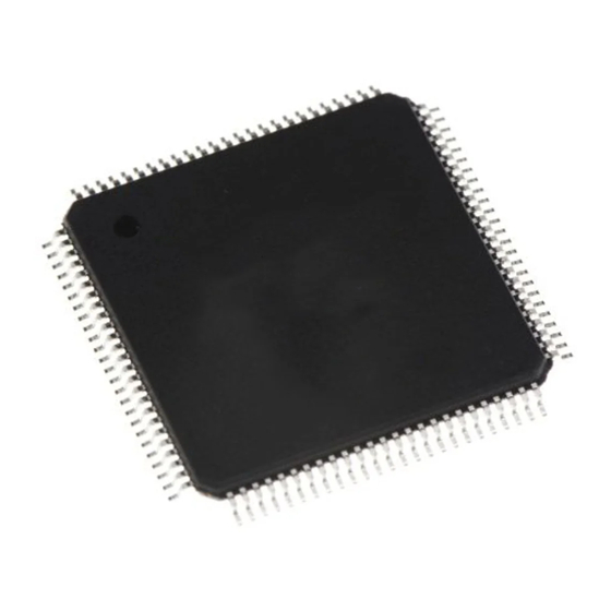
Section 1 Overview Section 1 Overview Overview • High-speed H8S/2600 central processing unit with an internal 16-bit architecture Upward-compatible with H8/300 and H8/300H CPUs on an object level Sixteen 16-bit general registers 69 basic instructions • Various peripheral functions ... - Page 38 Section 1 Overview • Compact package Package Package Code Body Size Pin Pitch × QFP-80 FP-80Q/FP-80QV 14.0 14.0 mm 0.65 mm Note: MMT, PPG, PC break controller, and DTC are not implemented in the H8S/2614 and H8S/2616. Rev. 6.00 Mar 15, 2006 page 2 of 570 REJ09B0211-0600...
-
Page 39: Internal Block Diagram
Section 1 Overview Internal Block Diagram Port D PA3/SCK2/POE3 PA2/RxD2/POE2 EXTAL PA1/TxD2/POE1 XTAL PA0/POE0 PLLVCL PLLCAP H8S/2600 CPU PLLVSS PB7/TIOCB5/PWOB STBY PB6/TIOCA5/PWOA PB5/TIOCB4/PVOB FWE/NC * PB4/TIOCA4/PVOA Interrupt controller PB3/TIOCD3/PUOB PB2/TIOCC3/PUOA PB1/TIOCB3/PCO φ PF7/ PC break controller PB0/TIOCA3/PCI (2 channels) PF3/ADTRG/IRQ3 PC5/SCK1/IRQ5 (mask ROM, PC4/RxD1... -
Page 40: Figure 1.2 Internal Block Diagram (Hd6432616 And Hd6432614)
Section 1 Overview Port D PA3/SCK2 PA2/RxD2 EXTAL PA1/TxD2 XTAL PLLVCL H8S/2600 CPU PLLCAP PLLVSS PB7/TIOCB5 STBY PB6/TIOCA5 PB5/TIOCB4 PB4/TIOCA4 Interrupt controller PB3/TIOCD3 PB2/TIOCC3 PB1/TIOCB3 PF7/φ PB0/TIOCA3 PF3/ADTRG/IRQ3 PC5/SCK1/IRQ5 PC4/RxD1 (mask ROM) PC3/TxD1 WDT × 1 channel PF0/IRQ2 PC2/SCK0/IRQ4 PC1/RxD0 PC0/TxD0 SCI ×... -
Page 41: Pin Arrangement
Section 1 Overview Pin Arrangement AVcc P93/AN11 P92/AN10 P91/AN9 PA3/SCK2/POE3 P90/AN8 PA2/RxD2/POE2 P47/AN7 PA1/TxD2/POE1 P46/AN6 PA0/POE0 P45/AN5 PB7/TIOCB5/PWOB P44/AN4 PB6/TIOCA5/PWOA P43/AN3 TOP VIEW PB5/TIOCB4/PVOB P42/AN2 (FP-80Q) PB4/TIOCA4/PVOA P41/AN1 PB3/TIOCD3/PUOB P40/AN0 PB2/TIOCC3/PUOA AVss P10/PO8/TIOCA0 PB1/TIOCB3/PCO P11/PO9/TIOCB0 PB0/TIOCA3/PCI P12/PO10/TIOCC0/TCLKA PC5/SCK1/IRQ5 Note: * The FWE pin is used only in the flash memory version. The NC pin is used only in the mask ROM versions. -
Page 42: Figure 1.4 Pin Arrangement (Hd6432616 And Hd6432614)
Section 1 Overview AVcc P93/AN11 P92/AN10 P91/AN9 PA3/SCK2 P90/AN8 PA2/RxD2 P47/AN7 PA1/TxD2 P46/AN6 P45/AN5 PB7/TIOCB5 P44/AN4 PB6/TIOCA5 P43/AN3 PB5/TIOCB4 TOP VIEW P42/AN2 (FP-80Q) PB4/TIOCA4 P41/AN1 PB3/TIOCD3 P40/AN0 PB2/TIOCC3 AVss P10/TIOCA0 PB1/TIOCB3 P11/TIOCB0 PB0/TIOCA3 P12/TIOCC0/TCLKA PC5/SCK1/IRQ5 Note: PPG and MMT pin functions are not implemented. Figure 1.4 Pin Arrangement (HD6432616 and HD6432614) Rev. -
Page 43: Pin Functions
Section 1 Overview Pin Functions Type Symbol Pin NO. Function Power Input Power supply pins. Connect all these pins to the Supply system power supply. Input Ground pins. Connect all these pins to the system power supply (0V). Output External capacitance pin for internal power-down power supply. - Page 44 Section 1 Overview Type Symbol Pin NO. Function Interrupts Input Nonmaskable interrupt pin. If this pin is not used, it should be fixed-high. IRQ5 Input These pins request a maskable interrupt. IRQ4 IRQ3 IRQ2 IRQ1 IRQ0 16-bit TCLKA Input These pins input an external clock. timer- TCLKB pulse unit...
- Page 45 Section 1 Overview Type Symbol Pin NO. Function Motor PUOA Output U-phase output pin for 6-phase non-overlap PWM manage- waveforms. ment timer U-phase output pin for 6-phase non-overlap PWM PUOB Output (MMT) waveforms PVOA Output V-phase output pin for 6-phase non-overlap PWM waveforms.
- Page 46 Section 1 Overview Type Symbol Pin NO. Function AN11 Input Analog input pins. converter AN10 ADTRG Input Pin for input of an external trigger to start A/D conversion. AVCC Input Power supply pin for the A/D converter. When the A/D converter is not used, connect this pin to the system power supply (+5V).
- Page 47 Section 1 Overview Type Symbol Pin NO. Function I/O ports Input/ Four input/output pins. Output Input/ Eight input/output pins. Output Input/ Eight input/output pins. Output Input/ Eight input/output pins. Output Input/ Eight input/output pins. Output Rev. 6.00 Mar 15, 2006 page 11 of 570 REJ09B0211-0600...
-
Page 48: Differences Between H8S/2612, H8S/2611, H8S/2614, And H8S/2616
Section 1 Overview Differences between H8S/2612, H8S/2611, H8S/2614, and H8S/2616 The amount of on-chip ROM and the specific on-chip modules implemented differ among the H8S/2612, H8S/2611, H8S/2614, and H8S/2616. Table 1.1 lists the specifications for these products. Note: The DTC, PBC, PPG, and MMT are not implemented in the H8S/2616 and H8S/2614, so these modules cannot be used on these products. -
Page 49: Section 2 Cpu
Section 2 CPU Section 2 CPU The H8S/2600 CPU is a high-speed central processing unit with an internal 32-bit architecture that is upward-compatible with the H8/300 and H8/300H CPUs. The H8S/2600 CPU has sixteen 16-bit general registers, can address a 16-Mbyte linear address space, and is ideal for realtime control. This section describes the H8S/2600 CPU. -
Page 50: Differences Between H8S/2600 Cpu And H8S/2000 Cpu
Section 2 CPU 16 × 16-bit register-register multiply: 4 states 32 ÷ 16-bit register-register divide: 20 states • Two CPU operating modes Normal mode * Advanced mode • Power-down state Transition to power-down state by SLEEP instruction ... -
Page 51: Differences From H8/300 Cpu
Section 2 CPU 2.1.2 Differences from H8/300 CPU In comparison to the H8/300 CPU, the H8S/2600 CPU has the following enhancements: • More general registers and control registers Eight 16-bit expanded registers, and one 8-bit and two 32-bit control registers, have been added. -
Page 52: Cpu Operating Modes
Section 2 CPU CPU Operating Modes The H8S/2600 CPU has two operating modes: normal and advanced. Normal mode supports a maximum 64-kbyte address space. Advanced mode supports a maximum 16-Mbyte total address space. The mode is selected by the mode pins. 2.2.1 Normal Mode The exception vector table and stack have the same structure as in the H8/300 CPU. -
Page 53: Advanced Mode
Section 2 CPU H'0000 Reset exception vector H'0001 H'0002 (Reserved for system use) H'0003 H'0004 H'0005 (Reserved for system use) H'0006 Exception vector table H'0007 H'0008 Exception vector 1 H'0009 H'000A Exception vector 2 H'000B Figure 2.1 Exception Vector Table (Normal Mode) EXR * Reserved * (16 bits) -
Page 54: Figure 2.3 Exception Vector Table (Advanced Mode)
Section 2 CPU • Instruction Set All instructions and addressing modes can be used. • Exception Vector Table and Memory Indirect Branch Addresses In advanced mode, the top area starting at H'00000000 is allocated to the exception vector table in units of 32 bits. In each 32 bits, the upper 8 bits are ignored and a branch address is stored in the lower 24 bits (figure 2.3). -
Page 55: Figure 2.4 Stack Structure In Advanced Mode
Section 2 CPU • Stack Structure In advanced mode, when the program counter (PC) is pushed onto the stack in a subroutine call, and the PC, condition-code register (CCR), and extended control register (EXR) are pushed onto the stack in exception handling, they are stored as shown in figure 2.4. When EXR is invalid, it is not pushed onto the stack. -
Page 56: Address Space
Section 2 CPU Address Space Figure 2.5 shows a memory map for the H8S/2600 CPU. The H8S/2600 CPU provides linear access to a maximum 64-kbyte address space in normal mode, and a maximum 16-Mbyte (architecturally 4-Gbyte) address space in advanced mode. The usable modes and address spaces differ depending on the product. -
Page 57: Register Configuration
Section 2 CPU Register Configuration The H8S/2600 CPU has the internal registers shown in figure 2.6. There are two types of registers; general registers and control registers. The control registers are a 24-bit program counter (PC), an 8-bit extended control register (EXR), an 8-bit condition code register (CCR), and a 64-bit multiply-accumulate register (MAC). -
Page 58: General Registers
Section 2 CPU 2.4.1 General Registers The H8S/2600 CPU has eight 32-bit general registers. These general registers are all functionally identical and can be used as both address registers and data registers. When a general register is used as a data register, it can be accessed as a 32-bit, 16-bit, or 8-bit register. Figure 2.7 illustrates the usage of the general registers. -
Page 59: Program Counter (Pc)
Section 2 CPU Free area SP (ER7) Stack area Figure 2.8 Stack 2.4.2 Program Counter (PC) This 24-bit counter indicates the address of the next instruction the CPU will execute. The length of all CPU instructions is 2 bytes (one word), so the least significant PC bit is ignored. (When an instruction is fetched, the least significant PC bit is regarded as 0.) 2.4.3 Extended Control Register (EXR) -
Page 60: Condition-Code Register (Ccr)
Section 2 CPU 2.4.4 Condition-Code Register (CCR) This 8-bit register contains internal CPU status information, including an interrupt mask bit (I) and half-carry (H), negative (N), zero (Z), overflow (V), and carry (C) flags. Operations can be performed on the CCR bits by the LDC, STC, ANDC, ORC, and XORC instructions. - Page 61 Section 2 CPU Bit Name Initial Value Description Interrupt Mask Bit Masks interrupts other than NMI when set to 1. NMI is accepted regardless of the I bit setting. The I bit is set to 1 by hardware at the start of an exception- handling sequence.
-
Page 62: Multiply-Accumulate Register (Mac)
Section 2 CPU Bit Name Initial Value Description undefined Carry Flag Set to 1 when a carry occurs, and cleared to 0 otherwise. Used by: • Add instructions, to indicate a carry • Subtract instructions, to indicate a borrow • Shift and rotate instructions, to indicate a carry The carry flag is also used as a bit accumulator by bit manipulation instructions. -
Page 63: Data Formats
Section 2 CPU Data Formats The H8S/2600 CPU can process 1-bit, 4-bit (BCD), 8-bit (byte), 16-bit (word), and 32-bit (longword) data. Bit-manipulation instructions operate on 1-bit data by accessing bit n (n = 0, 1, 2, …, 7) of byte operand data. The DAA and DAS decimal-adjust instructions treat byte data as two digits of 4-bit BCD data. -
Page 64: Figure 2.9 General Register Data Formats (2)
Section 2 CPU Data Type Register Number Data Format Word data Word data Longword data Legend: ERn: General register ER General register E General register R RnH: General register RH RnL: General register RL MSB: Most significant bit LSB: Least significant bit Figure 2.9 General Register Data Formats (2) Rev. -
Page 65: Memory Data Formats
Section 2 CPU 2.5.2 Memory Data Formats Figure 2.10 shows the data formats in memory. The H8S/2600 CPU can access word data and longword data in memory, however word or longword data must begin at an even address. If an attempt is made to access word or longword data at an odd address, an address error does not occur, however the least significant bit of the address is regarded as 0, so access begins the preceding address. -
Page 66: Instruction Set
Section 2 CPU Instruction Set The H8S/2600 CPU has 69 instructions. The instructions are classified by function in table 2.1. Table 2.1 Instruction Classification Function Instructions Size Types Data transfer B/W/L POP * , PUSH * LDM, STM MOVFPE * , MOVTPE * Arithmetic ADD, SUB, CMP, NEG... -
Page 67: Table Of Instructions Classified By Function
Section 2 CPU 2.6.1 Table of Instructions Classified by Function Tables 2.3 to 2.10 summarizes the instructions in each functional category. The notation used in tables 2.3 to 2.10 is defined below. Table 2.2 Operation Notation Symbol Description General register (destination) * General register (source) * General register * General register (32-bit register) -
Page 68: Table 2.3 Data Transfer Instructions
Section 2 CPU Table 2.3 Data Transfer Instructions Size * Instruction Function (EAs) → Rd, Rs → (EAd) B/W/L Moves data between two general registers or between a general register and memory, or moves immediate data to a general register. MOVFPE Cannot be used in this LSI. -
Page 69: Table 2.4 Arithmetic Operations Instructions
Section 2 CPU Table 2.4 Arithmetic Operations Instructions Size * Instruction Function Rd ± Rs → Rd, Rd ± #IMM → Rd B/W/L Performs addition or subtraction on data in two general registers, or on immediate data and data in a general register (immediate byte data cannot be subtracted from byte data in a general register. - Page 70 Section 2 CPU Size * Instruction Function Rd ÷ Rs → Rd DIVXS Performs signed division on data in two general registers: either 16 bits ÷ 8 bits → 8-bit quotient and 8-bit remainder or 32 bits ÷ 16 bits → 16-bit quotient and 16-bit remainder.
-
Page 71: Table 2.5 Logic Operations Instructions
Section 2 CPU Table 2.5 Logic Operations Instructions Size * Instruction Function Rd ∧ Rs → Rd, Rd ∧ #IMM → Rd B/W/L Performs a logical AND operation on a general register and another general register or immediate data. Rd ∨ Rs → Rd, Rd ∨ #IMM → Rd B/W/L Performs a logical OR operation on a general register and another general register or immediate data. -
Page 72: Table 2.7 Bit Manipulation Instructions
Section 2 CPU Table 2.7 Bit Manipulation Instructions Size * Instruction Function 1 → (<bit-No.> of <EAd>) BSET Sets a specified bit in a general register or memory operand to 1. The bit number is specified by 3-bit immediate data or the lower three bits of a general register. - Page 73 Section 2 CPU Size * Instruction Function C ⊕ (<bit-No.> of <EAd>) → C BXOR XORs the carry flag with a specified bit in a general register or memory operand and stores the result in the carry flag. C ⊕ ¬ (<bit-No.> of <EAd>) → C BIXOR XORs the carry flag with the inverse of a specified bit in a general register or memory operand and stores the result in the carry flag.
-
Page 74: Table 2.8 Branch Instructions
Section 2 CPU Table 2.8 Branch Instructions Instruction Size Function — Branches to a specified address if a specified condition is true. The branching conditions are listed below. Mnemonic Description Condition BRA (BT) Always (true) Always BRN (BF) Never (false) Never C ∨... -
Page 75: Table 2.9 System Control Instructions
Section 2 CPU Table 2.9 System Control Instructions Size * Instruction Function TRAPA — Starts trap-instruction exception handling. — Returns from an exception-handling routine. SLEEP — Causes a transition to a power-down state. (EAs) → CCR, (EAs) → EXR Moves the source operand contents or immediate data to CCR or EXR. Although CCR and EXR are 8-bit registers, word-size transfers are performed between them and memory. -
Page 76: Basic Instruction Formats
Section 2 CPU Table 2.10 Block Data Transfer Instructions Instruction Size Function if R4L ≠ 0 then EEPMOV.B — Repeat @ER5+ → @ER6+ R4L–1 → R4L Until R4L = 0 else next; if R4 ≠ 0 then EEPMOV.W — Repeat @ER5+ → @ER6+ R4–1 →... -
Page 77: Figure 2.11 Instruction Formats (Examples)
Section 2 CPU • Operation Field Indicates the function of the instruction, the addressing mode, and the operation to be carried out on the operand. The operation field always includes the first four bits of the instruction. Some instructions have two operation fields. •... -
Page 78: Addressing Modes And Effective Address Calculation
Section 2 CPU Addressing Modes and Effective Address Calculation The H8S/2600 CPU supports the eight addressing modes listed in table 2.11. Each instruction uses a subset of these addressing modes. Arithmetic and logic instructions can use the register direct and immediate modes. Data transfer instructions can use all addressing modes except program- counter relative and memory indirect. -
Page 79: Register Indirect With Displacement-@(D:16, Ern) Or @(D:32, Ern)
Section 2 CPU 2.7.3 Register Indirect with Displacement—@(d:16, ERn) or @(d:32, ERn) A 16-bit or 32-bit displacement contained in the instruction is added to an address register (ERn) specified by the register field of the instruction, and the sum gives the address of a memory operand. -
Page 80: Immediate-#Xx:8, #Xx:16, Or #Xx:32
Section 2 CPU Table 2.12 Absolute Address Access Ranges Normal Mode * Absolute Address Advanced Mode Data address 8 bits (@aa:8) H'FF00 to H'FFFF H'FFFF00 to H'FFFFFF 16 bits (@aa:16) H'0000 to H'FFFF H'000000 to H'007FFF, H'FF8000 to H'FFFFFF 32 bits (@aa:32) H'000000 to H'FFFFFF Program instruction 24 bits (@aa:24) -
Page 81: Effective Address Calculation
Section 2 CPU Note that the first part of the address range is also the exception vector area. For further details, refer to section 4, Exception Handling. If an odd address is specified in word or longword memory access, or as a branch address, the least significant bit is regarded as 0, causing data to be accessed or instruction code to be fetched at the address preceding the specified address. - Page 82 Section 2 CPU Table 2.13 Effective Address Calculation Addressing Mode and Instruction Format Effective Address Calculation Effective Address (EA) Register direct (Rn) Operand is general register contents. Register indirect (@ERn) General register contents General register contents Sign extension Register indirect with post-increment or pre-decrement •...
- Page 83 Section 2 CPU Addressing Mode and Instruction Format Effective Address Calculation Effective Address (EA) Absolute address Sign extension Immediate Operand is immediate data. PC contents Sign extension Memory contents Memory contents Note: Normal mode is not available in this LSI. Rev.
-
Page 84: Processing States
Section 2 CPU Processing States The H8S/2600 CPU has five main processing states: the reset state, exception handling state, program execution state, bus-released state, and power-down state. Figure 2.14 shows a diagram of the processing states. Figure 2.13 indicates the state transitions. •... -
Page 85: Usage Notes
Section 2 CPU Reset state Exception handling state Bus-released state Request for End of End of exception exception request bus request handling handling Program execution state Program halt state SLEEP instruction Notes: From any state, a transition to hardware standby mode occurs when STBY goes low. * From any state except hardware standby mode, a transition to the reset state occurs whenever RES goes low. - Page 86 Section 2 CPU Rev. 6.00 Mar 15, 2006 page 50 of 570 REJ09B0211-0600...
-
Page 87: Section 3 Mcu Operating Modes
Section 3 MCU Operating Modes Section 3 MCU Operating Modes Operating Mode Selection This LSI supports only operating mode 7, that is, the advanced single-chip mode. The operating mode is determined by the setting of the mode pins (MD2 to MD0). Only mode 7 can be used in this LSI. -
Page 88: Mode Control Register(Mdcr)
Section 3 MCU Operating Modes 3.2.1 Mode Control Register(MDCR) Bit Name Intial Value Descriptions — Reserved Only 1 should be written to this bit. 6 to 3 — All 0 — Reserved These bits are always read as 0 and cannot be modified. -
Page 89: System Control Register(Syscr)
Section 3 MCU Operating Modes 3.2.2 System Control Register(SYSCR) SYSCR is an 8-bit readable/writable register that selects saturating or non-saturating calculation for the MAC instruction, selects the interrupt control mode and the detected edge for NMI, and enables or disables on-chip RAM. Bit Name Intial Value Descriptions... -
Page 90: Pin Functions In Each Operating Mode
Section 3 MCU Operating Modes Pin Functions in Each Operating Mode The CPU can access a 16-Mbyte address space in advanced mode. The on-chip ROM is enabled, however external addresses cannot be accessed. All I/O ports are available for use as input-output ports. 3.3.1 Pin Functions Table 3.2 shows their functions in mode 7. -
Page 91: Address Map
Section 3 MCU Operating Modes Address Map Figure 3.1 shows the address map in each operating mode. H8S/2612, H8S/2616 H8S/2611, H8S/2614 ROM: 128 kbytes, RAM: 4 kbytes ROM: 64 kbytes, RAM: 4 kbytes Mode 7 Mode 7 Advanced single-chip mode Advanced single-chip mode H'000000 H'000000... - Page 92 Section 3 MCU Operating Modes Rev. 6.00 Mar 15, 2006 page 56 of 570 REJ09B0211-0600...
-
Page 93: Section 4 Exception Handling
Section 4 Exception Handling Section 4 Exception Handling Exception Handling Types and Priority As table 4.1 indicates, exception handling may be caused by a reset, trap instruction, or interrupt. Exception handling is prioritized as shown in table 4.1. If two or more exceptions occur simultaneously, they are accepted and processed in order of priority. -
Page 94: Table 4.2 Exception Handling Vector Table
Section 4 Exception Handling Table 4.2 Exception Handling Vector Table Vector Address * Vector Normal Mode * Exception Source Number Advanced Mode Power-on reset H'0000 to H'0001 H'0000 to H'0003 Manual reset * H'0002 to H'0003 H'0004 to H'0007 Reserved for system use H'0004 to H'0005 H'0008 to H'000B H'0006 to H'0007... -
Page 95: Reset
Section 4 Exception Handling Reset A reset has the highest exception priority. When the RES pin goes low, all processing halts and this LSI enters the reset. To ensure that this LSI is reset, hold the RES pin low for at least 20 ms at power-up. To reset the chip during operation, hold the RES pin low for at least 20 states. -
Page 96: Figure 4.1 Reset Sequence (Advanced Mode With On-Chip Rom Enabled)
Section 4 Exception Handling Prefetch of first Internal Vector fetch program instruction processing φ Internal address bus Internal read signal Internal write High signal Internal data (1)(3) Reset exception handling vector address(when reset, (1)=H'000000, (3)=H'000002) (2)(4) Start address (contents of reset exception handling vector address) Start address ((5)=(2)(4)) First program instruction Figure 4.1 Reset Sequence (Advanced Mode with On-Chip ROM Enabled) -
Page 97: Interrupts After Reset
Section 4 Exception Handling Internal Prefetch of first processing program instruction Vector fetch φ Address bus HWR, LWR High D15 to D0 (1)(3) Reset exception handling vector address(when reset, (1)=H'000000, (3)=H'000002) (2)(4) Start address (contents of reset exception handling vector address) Start address ((5)=(2)(4)) First program instruction Note: * Three program wait states are inserted. -
Page 98: Traces
Section 4 Exception Handling module registers cannot be read or written to. Register reading and writing is enabled when the module stop mode is exited. Traces Traces are enabled in interrupt control mode 2. Trace mode is not activated in interrupt control mode 0, irrespective of the state of the T bit. -
Page 99: Trap Instruction
Section 4 Exception Handling A vector address corresponding to the interrupt source is generated, the start address is loaded from the vector table to the PC, and program execution begins from that address. Trap Instruction Trap instruction exception handling starts when a TRAPA instruction is executed. Trap instruction exception handling can be executed at all times in the program execution state. -
Page 100: Stack Status After Exception Handling
Section 4 Exception Handling Stack Status after Exception Handling Figures 4.3 shows the stack after completion of trap instruction exception handling and interrupt exception handling. (a) Normal Modes Reserved * CCR * CCR * PC (16 bits) PC (16 bits) Interrupt control mode 0 Interrupt control mode 2 (b) Advanced Modes... -
Page 101: Usage Note
Section 4 Exception Handling Usage Note When accessing word data or longword data, this LSI assumes that the lowest address bit is 0. The stack should always be accessed by word transfer instruction or longword transfer instruction, and the value of the stack pointer (SP, ER7) should always be kept even. Use the following instructions to save registers: PUSH.W (or MOV.W Rn, @-SP) - Page 102 Section 4 Exception Handling Rev. 6.00 Mar 15, 2006 page 66 of 570 REJ09B0211-0600...
-
Page 103: Section 5 Interrupt Controller
Section 5 Interrupt Controller Section 5 Interrupt Controller Features • Two interrupt control modes Any of two interrupt control modes can be set by means of the INTM1 and INTM0 bits in the system control register (SYSCR). • Priorities settable with IPR ... -
Page 104: Figure 5.1 Block Diagram Of Interrupt Controller
Section 5 Interrupt Controller A block diagram of the interrupt controller is shown in figure 5.1. INTM1, INTM0 SYSCR NMIEG NMI input NMI input unit Interrupt request IRQ input unit IRQ input Vector number Priority ISCR determination Internal interrupt request I2 to I0 SWDTEND to TEI2 Interrupt controller... -
Page 105: Input/Output Pins
Section 5 Interrupt Controller Input/Output Pins Table 5.1 summarizes the pins of the interrupt controller. Table 5.1 Pin Configuration Name Function Input Nonmaskable external interrupt Rising or falling edge can be selected IRQ5 Input Maskable external interrupts IRQ4 Input Rising, falling, or both edges, or level sensing, can be selected IRQ3 Input IRQ2... -
Page 106: Interrupt Priority Registers A To H, J, K, M (Ipra To Iprh,Iprj, Iprk, Iprm)
Section 5 Interrupt Controller 5.3.1 Interrupt Priority Registers A to H, J, K, M (IPRA to IPRH,IPRJ, IPRK, IPRM) The IPR registers are eleven 8-bit readable/writable registers that set priorities (levels 7 to 0) for interrupts other than NMI. The correspondence between interrupt sources and IPR settings is shown in table 5.2. Setting a value in the range from H'0 to H'7 in the 3-bit groups of bits 0 to 2 and 4 to 6 sets the priority of the corresponding interrupt. -
Page 107: Irq Enable Register (Ier)
Section 5 Interrupt Controller 5.3.2 IRQ Enable Register (IER) IER is an 8-bit readable/writable register that controls the enabling and disabling of interrupt requests IRQ0 to IRQ5. Bit Name Initial Value Description − 7, 6 All 0 Reserved Only 0 should be written to these bits. IRQ5E IRQ5 Enable The IRQ5 interrupt request is enabled when this bit... - Page 108 Section 5 Interrupt Controller Bit Name Initial Value Description − 15 to All 0 Reserved Only 0 should be written to these bits. IRQ5SCB IRQ5 Sense Control B IRQ5SCA IRQ5 Sense Control A 00: Interrupt request generated at IRQ5 input level 01: Interrupt request generated at falling edge of IRQ5 input 10: Interrupt request generated at rising edge of...
- Page 109 Section 5 Interrupt Controller Bit Name Initial Value Description IRQ2SCB IRQ2 Sense Control B IRQ2SCA IRQ2 Sense Control A 00: Interrupt request generated at IRQ2 input level 01: Interrupt request generated at falling edge of IRQ2 input 10: Interrupt request generated at rising edge of IRQ2 input 11: Interrupt request generated at both falling and rising edges of IRQ2 input...
-
Page 110: Irq Status Register (Isr)
Section 5 Interrupt Controller 5.3.4 IRQ Status Register (ISR) ISR is an 8-bit readable/writable register that indicates the status of IRQ0 to IRQ5 interrupt requests. Bit Name Initial Value Description − 7, 6 All 0 Reserved Only 0 should be written to these bits. IRQ5F [Setting condition] IRQ4F... -
Page 111: Interrupt
Section 5 Interrupt Controller Interrupt 5.4.1 External Interrupts There are seven external interrupts: NMI and IRQ0 to IRQ5. These interrupts can be used to restore this LSI from software standby mode. NMI Interrupt: NMI is the highest-priority interrupt, and is always accepted by the CPU regardless of the interrupt control mode or the status of the CPU interrupt mask bits. -
Page 112: Internal Interrupts
Section 5 Interrupt Controller 5.4.2 Internal Interrupts The sources for internal interrupts from on-chip supporting modules have the following features: • For each on-chip supporting module there are flags that indicate the interrupt request status, and enable bits that select enabling or disabling of these interrupts. If both of these are set to 1 for a particular interrupt source, an interrupt request is issued to the interrupt controller. -
Page 113: Table 5.2 Interrupt Sources, Vector Addresses, And Interrupt Priorities
Section 5 Interrupt Controller Table 5.2 Interrupt Sources, Vector Addresses, and Interrupt Priorities Vector Address * Interrupt Origin of Vector Advanced Source Interrupt Source Number Mode Priority External H'001C High IRQ0 H'0040 IPRA6 to IPRA4 IRQ1 H'0044 IPRA2 to IPRA0 IRQ2 H'0048 IPRB6 to IPRB4... - Page 114 Section 5 Interrupt Controller Vector Address * Interrupt Origin of Vector Advanced Source Interrupt Source Number Mode Priority TGID_3 H'00CC High channel 3 TCIV_3 H'00D0 TGIA_4 H'00E0 IPRH6 to IPRH4 channel 4 TGIB_4 H'00E4 TCIV_4 H'00E8 TCIU_4 H'00EC TGIA_5 H'00F0 IPRH2 to IPRH0 channel 5 TGIB_5...
-
Page 115: Interrupt Control Modes And Interrupt Operation
Section 5 Interrupt Controller Interrupt Control Modes and Interrupt Operation The interrupt controller has two modes: interrupt control mode 0 and interrupt control mode 2. Interrupt operations differ depending on the interrupt control mode. The interrupt control mode is selected by SYSCR. Table 5.3 shows the differences between interrupt control mode 0 and interrupt control mode 2. -
Page 116: Figure 5.3 Flowchart Of Procedure Up To Interrupt Acceptance In Interrupt Control
Section 5 Interrupt Controller 7. The CPU generates a vector address for the accepted interrupt and starts execution of the interrupt handling routine at the address indicated by the contents of the vector address in the vector table. Program execution status Interrupt generated? I = 0 Hold... -
Page 117: Interrupt Control Mode 2
Section 5 Interrupt Controller 5.6.2 Interrupt Control Mode 2 In interrupt control mode 2, mask control is applied to eight levels for interrupt requests other than NMI by comparing the EXR interrupt mask level (I2 to I0 bits) in the CPU and the IPR setting. Figure 5.4 shows a flowchart of the interrupt acceptance operation in this case. -
Page 118: Figure 5.4 Flowchart Of Procedure Up To Interrupt Acceptance In Control Mode 2
Section 5 Interrupt Controller Program execution status Interrupt generated? Level 7 interrupt? Level 6 interrupt? Mask level 6 or below? Level 1 interrupt? Mask level 5 or below? Mask level 0? Hold Save PC, CCR, and EXR pending Clear T bit to 0 Update mask level Read vector address Branch to interrupt handling routine... -
Page 119: Interrupt Exception Handling Sequence
Section 5 Interrupt Controller 5.6.3 Interrupt Exception Handling Sequence Figure 5.5 shows the interrupt exception handling sequence. The example shown is for the case where interrupt control mode 0 is set in advanced mode, and the program area and stack area are in on-chip memory. -
Page 120: Figure 5.5 Interrupt Exception Handling
Section 5 Interrupt Controller Figure 5.5 Interrupt Exception Handling Rev. 6.00 Mar 15, 2006 page 84 of 570 REJ09B0211-0600... -
Page 121: Interrupt Response Times
Section 5 Interrupt Controller 5.6.4 Interrupt Response Times Table 5.4 shows interrupt response times - the interval between generation of an interrupt request and execution of the first instruction in the interrupt handling routine. The execution status symbols used in table 5.4 are explained in table 5.5. This LSI is capable of fast word transfer to on-chip memory, has the program area in on-chip ROM and the stack area in on-chip RAM, enabling high-speed processing. -
Page 122: Dtc Activation By Interrupt
Section 5 Interrupt Controller Table 5.5 Number of States in Interrupt Handling Routine Execution Status Object of Access External Device * 8 Bit Bus 16 Bit Bus Internal 2-State 3-State 2-State 3-State Symbol Memory Access Access Access Access Instruction fetch 6 + 2m 3 + m Branch address read... -
Page 123: Instructions That Disable Interrupts
Section 5 Interrupt Controller The above contention will not occur if an enable bit or interrupt source flag is cleared to 0 while the interrupt is masked. TIER_0 write cycle by CPU TCIVexception handling φ Internal TIER_0 address address bus Internal write signal TCIEV... -
Page 124: Interrupts During Execution Of Eepmov Instruction
Section 5 Interrupt Controller 5.7.4 Interrupts during Execution of EEPMOV Instruction Interrupt operation differs between the EEPMOV.B instruction and the EEPMOV.W instruction. With the EEPMOV.B instruction, an interrupt request (including NMI) issued during the transfer is not accepted until the move is completed. With the EEPMOV.W instruction, if an interrupt request is issued during the transfer, interrupt exception handling starts at a break in the transfer cycle. -
Page 125: Section 6 Pc Break Controller (Pbc)
Section 6 PC Break Controller (PBC) Section 6 PC Break Controller (PBC) The PC break controller (PBC) provides functions that simplify program debugging. Using these functions, it is easy to create a self-monitoring debugger, enabling programs to be debugged with the chip alone, without using an in-circuit emulator. -
Page 126: Register Descriptions
Section 6 PC Break Controller (PBC) BARA BCRA Mask control Control Comparator logic Match signal Internal address PC break Access interrupt status Control Comparator logic Match signal Mask control BARB BCRB Figure 6.1 Block Diagram of PC Break Controller Register Descriptions The PC break controller has the following registers. -
Page 127: Break Address Register B (Barb)
Section 6 PC Break Controller (PBC) 6.2.2 Break Address Register B (BARB) BARB is the channel B break address register. The bit configuration is the same as for BARA. 6.2.3 Break Control Register A (BCRA) BCRA controls channel A PC breaks. BCRA also contains a condition match flag. Bit Name Initial Value Description... -
Page 128: Break Control Register B (Bcrb)
Section 6 PC Break Controller (PBC) 6.2.4 Break Control Register B (BCRB) BCRB is the channel B break control register. The bit configuration is the same as for BCRA. Operation The operation flow from break condition setting to PC break interrupt exception handling is shown in section 6.3.1, PC Break Interrupt Due to Instruction Fetch, and 6.3.2, PC Break Interrupt Due to Data Access, taking the example of channel A. -
Page 129: Notes On Pc Break Interrupt Handling
Section 6 PC Break Controller (PBC) 4. After priority determination by the interrupt controller, PC break interrupt exception handling is started. 6.3.3 Notes on PC Break Interrupt Handling • When a PC break interrupt is generated at the transfer address of an EEPMOV.B instruction PC break exception handling is executed after all data transfers have been completed and the EEPMOV.B instruction has ended. -
Page 130: When Instruction Execution Is Delayed By One State
Section 6 PC Break Controller (PBC) 6.3.5 When Instruction Execution is Delayed by One State While the break interrupt enable bit is set to 1, instruction execution is one state later than usual. • For 1-word branch instructions (Bcc d:8, BSR, JSR, JMP, TRAPA, RTE, and RTS) in on-chip ROM or RAM. -
Page 131: Usage Notes
Section 6 PC Break Controller (PBC) Usage Notes 6.4.1 Module Stop Mode Setting PBC operation can be disabled or enabled using the module stop control register. The initial setting is for PBC operation to be halted. Register access is enabled by clearing module stop mode. -
Page 132: Pc Break Set For Instruction Fetch At Address Following Bcc Instruction
Section 6 PC Break Controller (PBC) disabled for a 3-state period in the case of LDC, ANDC, ORC, and XOR, the next instruction is always executed. For details, see section 5, Interrupt Controller. 6.4.7 PC Break Set for Instruction Fetch at Address Following Bcc Instruction When a PC break is set for an instruction fetch at an address following a Bcc instruction: A PC break interrupt is generated if the instruction at the next address is executed in accordance with the branch condition, and is not generated if the instruction at the next address is not... -
Page 133: Section 7 Bus Controller
Section 7 Bus Controller Section 7 Bus Controller The H8S/2600 CPU is driven by a system clock, denoted by the symbol ø. The bus controller controls a memory cycle and a bus cycle. Different methods are used to access on-chip memory and on-chip support modules. The bus controller also has a bus arbitration function, and controls the operation of the internal bus masters: the CPU and data transfer controller (DTC). -
Page 134: On-Chip Support Module Access Timing
Section 7 Bus Controller 7.1.2 On-Chip Support Module Access Timing The on-chip support modules, except for HCAN, MMT, and POE, are accessed in two states. The data bus is either 8 bits or 16 bits wide, depending on the particular internal I/O register being accessed. -
Page 135: On-Chip Hcan Module Access Timing
Section 7 Bus Controller 7.1.3 On-Chip HCAN Module Access Timing On-chip HCAN module access is performed in four states. The data bus width is 16 bits. Wait states can be inserted by means of a wait request from the HCAN. On-chip HCAN module access timing is shown in figures 7.3. -
Page 136: On-Chip Mmt Module Access Timing
Section 7 Bus Controller 7.1.4 On-Chip MMT Module Access Timing On-chip MMT module and POE access are performed in three states. The data width is 16 bits. On-chip MMT module access timings are shown in figure 7.4. Bus cycle φ Internal address bus Address MMT read signal... -
Page 137: Bus Arbitration
Section 7 Bus Controller Bus Arbitration The Bus Controller has a bus arbiter that arbitrates bus master operations. There are two bus masters, the CPU and DTC, which perform read/write operations when they control the bus. Note: No DTC is implemented in the H8S/2614 and H8S/2616. 7.2.1 Order of Priority of the Bus Masters Each bus master requests the bus by means of a bus request signal. - Page 138 Section 7 Bus Controller Rev. 6.00 Mar 15, 2006 page 102 of 570 REJ09B0211-0600...
-
Page 139: Section 8 Data Transfer Controller (Dtc)
Section 8 Data Transfer Controller (DTC) Section 8 Data Transfer Controller (DTC) This LSI includes a data transfer controller (DTC). The DTC can be activated by an interrupt or software, to transfer data. Figure 8.1 shows a block diagram of the DTC. The DTC’s register information is stored in the on-chip RAM. -
Page 140: Figure 8.1 Block Diagram Of Dtc
Section 8 Data Transfer Controller (DTC) Internal address bus On-chip Interrupt controller Interrupt request CPU interrupt Internal data bus request Legend: MRA, MRB: DTC mode registers A and B CRA, CRB: DTC transfer count registers A and B SAR: DTC source address register DAR: DTC destination address register DTCERA to DTCERG:... -
Page 141: Register Configuration
Section 8 Data Transfer Controller (DTC) Register Configuration The DTC has the following registers. • DTC mode register A (MRA) • DTC mode register B (MRB) • DTC source address register (SAR) • DTC destination address register (DAR) • DTC transfer count register A (CRA) •... -
Page 142: Dtc Mode Register A (Mra)
Section 8 Data Transfer Controller (DTC) 8.2.1 DTC Mode Register A (MRA) MRA is an 8-bit register that selects the DTC operating mode. Bit Name Initial Value Description Undefined — Source Address Mode 1 and 0 Undefined — These bits specify an SAR operation after a data transfer. -
Page 143: Dtc Mode Register B (Mrb)
Section 8 Data Transfer Controller (DTC) 8.2.2 DTC Mode Register B (MRB) MRB is an 8-bit register that selects the DTC operating mode. Bit Name Initial Value Description CHNE Undefined — DTC Chain Transfer Enable When this bit is set to 1, a chain transfer will be performed. -
Page 144: Dtc Transfer Count Register B (Crb)
Section 8 Data Transfer Controller (DTC) In repeat mode or block transfer mode, the CRA is divided into two parts; the upper 8 bits (CRAH) and the lower 8 bits (CRAL). CRAH holds the number of transfers while CRAL functions as an 8-bit transfer counter (1 to 256). CRAL is decremented by 1 every time data is transferred, and the contents of CRAH are sent when the count reaches H'00. -
Page 145: Dtc Vector Register (Dtvecr)
Section 8 Data Transfer Controller (DTC) 8.2.8 DTC Vector Register (DTVECR) DTVECR is an 8-bit readable/writable register that enables or disables DTC activation by software, and sets a vector number for the software activation interrupt. Bit Name Initial Value Description SWDTE DTC Software Activation Enable Setting this bit to 1 activates DTC. -
Page 146: Location Of Register Information And Dtc Vector Table
Section 8 Data Transfer Controller (DTC) Source flag cleared Clear controller Clear DTCER Clear request Select On-chip supporting module IRQ interrupt Interrupt request Interrupt controller DTVECR Interrupt mask Figure 8.2 Block Diagram of DTC Activation Source Control Location of Register Information and DTC Vector Table Locate the register information in the on-chip RAM (addresses: H'FFEBC0 to H'FFEFBF). -
Page 147: Figure 8.3 Correspondence Between Dtc Vector Address And Register Information
Section 8 Data Transfer Controller (DTC) Lower address Register information start address Register information Chain transfer Register information for 2nd transfer in chain transfer 4 bytes Figure 8.3 Correspondence between DTC Vector Address and Register Information Rev. 6.00 Mar 15, 2006 page 111 of 570 REJ09B0211-0600... -
Page 148: Table 8.1 Interrupt Sources, Dtc Vector Addresses, And Corresponding Dtces
Section 8 Data Transfer Controller (DTC) Table 8.1 Interrupt Sources, DTC Vector Addresses, and Corresponding DTCEs Interrupt Origin of Vector DTCE * Source Interrupt Source Number Vector Address Priority Software Write to DTVECR DTVECR H'0400 + (vector — High number × 2) External pin IRQ0 H'0420... - Page 149 Section 8 Data Transfer Controller (DTC) Interrupt Origin of Vector DTCE * Source Interrupt Source Number Vector Address Priority — Reserved for H'0480 DTCED3 High system use H'0482 DTCED2 H'0488 DTCED1 H'048A DTCED0 H'0490 DTCEE7 H'0492 DTCEE6 H'0494 DTCEE5 H'0496 DTCEE4 RXI_0 H'04A2...
-
Page 150: Operation
Section 8 Data Transfer Controller (DTC) Operation Register information is stored in on-chip memory. When activated, the DTC reads register information in on-chip memory and transfers data. After the data transfer, the DTC writes updated register information back to the memory. The pre-storage of register information in memory makes it possible to transfer data over any required number of channels. -
Page 151: Normal Mode
Section 8 Data Transfer Controller (DTC) 8.5.1 Normal Mode In normal mode, one operation transfers one byte or one word of data. Table 8.2 lists the register information in normal mode. From 1 to 65,536 transfers can be specified. Once the specified number of transfers have been completed, a CPU interrupt can be requested. -
Page 152: Repeat Mode
Section 8 Data Transfer Controller (DTC) 8.5.2 Repeat Mode In repeat mode, one operation transfers one byte or one word of data. Table 8.3 lists the register information in repeat mode. From 1 to 256 transfers can be specified. Once the specified number of transfers have ended, the initial state of the transfer counter and the address register specified as the repeat area is restored, and transfer is repeated. -
Page 153: Block Transfer Mode
Section 8 Data Transfer Controller (DTC) 8.5.3 Block Transfer Mode In block transfer mode, one operation transfers one block of data. Either the transfer source or the transfer destination is designated as a block area. Table 8.4 lists the register information in block transfer mode. -
Page 154: Figure 8.7 Memory Mapping In Block Transfer Mode
Section 8 Data Transfer Controller (DTC) First block Block area Transfer Nth block Figure 8.7 Memory Mapping in Block Transfer Mode Rev. 6.00 Mar 15, 2006 page 118 of 570 REJ09B0211-0600... -
Page 155: Chain Transfer
Section 8 Data Transfer Controller (DTC) 8.5.4 Chain Transfer Setting the CHNE bit in MRB to 1 enables a number of data transfers to be performed consecutively in response to a single transfer request. SAR, DAR, CRA, CRB, MRA, and MRB, which define data transfers, can be set independently. -
Page 156: Interrupts
Section 8 Data Transfer Controller (DTC) 8.5.5 Interrupts An interrupt request is issued to the CPU when the DTC has completed the specified number of data transfers, or a data transfer for which the DISEL bit was set to 1. In the case of interrupt activation, the interrupt set as the activation source is generated. -
Page 157: Number Of Dtc Execution States
Section 8 Data Transfer Controller (DTC) φ DTC activation request request Data transfer Vector read Read Write Read Write Address Transfer Transfer information read information write Figure 8.10 DTC Operation Timing (Example of Block Transfer Mode, with Block Size of 2) φ... -
Page 158: Table 8.5 Dtc Execution Status
Section 8 Data Transfer Controller (DTC) Table 8.5 DTC Execution Status Register Information Internal Vector Read Read/Write Data Read Data Write Operations Mode Normal Repeat Block transfer Legend: N: Block size (initial setting of CRAH and CRAL) Table 8.6 Number of States Required for Each Execution Status On-Chip I/O External Devices * Object to be Accessed... -
Page 159: Procedures For Using Dtc
Section 8 Data Transfer Controller (DTC) Procedures for Using DTC 8.6.1 Activation by Interrupt The procedure for using the DTC with interrupt activation is as follows: 1. Set the MRA, MRB, SAR, DAR, CRA, and CRB register information in on-chip RAM. 2. -
Page 160: Chain Transfer
Section 8 Data Transfer Controller (DTC) SCI RDR address in SAR, the start address of the RAM area where the data will be received in DAR, and 128 (H'0080) in CRA. CRB can be set to any value. 2. Set the start address of the register information at the DTC vector address. 3. -
Page 161: Software Activation
Section 8 Data Transfer Controller (DTC) 6. Set TGRA as an output compare register (output disabled) with TIOR, and enable the TGIA interrupt with TIER. 7. Set the initial output value in PODR, and the next output value in NDR. Set bits in DDR and NDER for which output is to be performed to 1. -
Page 162: Usage Notes
Section 8 Data Transfer Controller (DTC) Usage Notes 8.8.1 Module Stop Mode Setting DTC operation can be disabled or enabled using the module stop control register. The initial setting is for DTC operation to be halted. Register access is enabled by clearing module stop mode. -
Page 163: Section 9 I/O Ports
Section 9 I/O Ports Section 9 I/O Ports Table 9.1 summarizes the port functions. The pins of each port also have other functions such as input/output or interrupt input pins of on-chip supporting modules. Each I/O port includes a data direction register (DDR) that controls input/output, a data register (DR) that stores output data, and a port register (PORT) used to read the pin states. -
Page 164: Table 9.1 Port Functions
Section 9 I/O Ports Table 9.1 Port Functions Port and Input/Output and Port Description Other Functions Name Output Type Port 1 General I/O port also P17/PO15/TIOCB2/TCLKD functioning as TPU I/O pins, P16/PO14/TIOCA2/IRQ1 PPG output pins, and P15/PO13/TIOCB1/TCLKC interrupt input pins P14/PO12/TIOCA1/IRQ0 Note: The H8S/2614 and H8S/2616 have no... - Page 165 Section 9 I/O Ports Port and Input/Output and Port Description Other Functions Name Output Type Port B General I/O port also PB7/TIOCB5/PWOB Built-in MOS input pull-up functioning as TPU_5, Push-pull or open-drain PB6/TIOCA5/PWOA TPU_4, and TPU_3 I/O output selectable PB5/TIOCB4/PVOB pins, and MMT I/O pins PB4/TIOCA4/PVOA Note: The H8S/2614 and...
-
Page 166: Port 1
Section 9 I/O Ports Port 1 Port 1 is an 8-bit I/O port and has the following registers. For details on register addresses and register states during each process, refer to appendix A, On-Chip I/O Register. • Port 1 data direction register (P1DDR) •... -
Page 167: Port 1 Data Register (P1Dr)
Section 9 I/O Ports 9.1.2 Port 1 Data Register (P1DR) P1DR is an 8-bit readable/writable register that stores output data for port 1 pins. Bit Name Initial Value Description P17DR Output data for a pin is stored when the pin is specified as a general purpose I/O port. -
Page 168: Pin Functions
Section 9 I/O Ports 9.1.4 Pin Functions Port 1 pins also function as TPU I/O pins, PPG output pins, and interrupt input pins. The correspondence between the register specification and the pin functions is shown below. Note: The H8S/2614 and H8S/2616 have no PPG outputs. Table 9.2 P17 Pin Function TPU Channel... -
Page 169: Table 9.4 P15 Pin Function
Section 9 I/O Ports Table 9.4 P15 Pin Function TPU Channel Output Input or Initial Value 1 Setting * P15DDR — NDER13 — — Pin function TIOCB1 output P15 input P15 output PO13 output TIOCB1 input TCLKC input Note: * For details on the TPU channel specification, refer to section 10, 16-Bit Timer Pulse Unit (TPU). -
Page 170: Table 9.7 P12 Pin Function
Section 9 I/O Ports Table 9.7 P12 Pin Function TPU Channel Output Input or Initial Value 0 Setting * P12DDR — NDER10 — — Pin function TIOCC0 output P12 input P12 output PO10 output TIOCC0 input TCLKA input Note: * For details on the TPU channel specification, refer to section 10, 16-Bit Timer Pulse Unit (TPU). -
Page 171: Port 4
Section 9 I/O Ports Port 4 Port 4 is an 8-bit input-only port. Port 4 pins also function as A/D converter analog input pins. For details on register addresses, refer to appendix A, On-Chip I/O Register. • Port 4 register (PORT4) 9.2.1 Port 4 Register (PORT4) PORT4 is an 8-bit read-only register that shows port 4 pin states. -
Page 172: Port 9
Section 9 I/O Ports Port 9 Port 9 is a 4-bit input-only port. Port 9 pins also function as A/D converter analog input pins. Port 9 has the following registers. For details on register addresses, refer to appendix A, On-Chip I/O Register. -
Page 173: Port A
Section 9 I/O Ports Port A Port A is a 4-bit I/O port that also has other functions. Port A has the following registers. For details on register addresses and register states during each processing, refer to appendix A, On- Chip I/O Register. -
Page 174: Port A Data Register (Padr)
Section 9 I/O Ports 9.4.2 Port A Data Register (PADR) PADR is an 8-bit readable/writable register that stores output data for port A pins. Bit Name Initial Value Description — Undefined — Reserved These bits are read as an undefined value. —... -
Page 175: Port A Pull-Up Mos Control Register (Papcr)
Section 9 I/O Ports 9.4.4 Port A Pull-Up MOS Control Register (PAPCR) PAPCR is an 8-bit register that controls the MOS input pull-up function. Bit Name Initial Value Description — Undefined — Reserved These bits are read as an undefined value. —... -
Page 176: Pin Functions
Section 9 I/O Ports 9.4.6 Pin Functions Port A pins also function as SCI_2 I/O, interrupt input, and POE input pins. The correspondence between the register specification and the pin functions is shown below. Note: The H8S/2614 and H8S/2616 have no POE input pins. Table 9.10 PA3 Pin Function POE3E CKE1... -
Page 177: Port B
Section 9 I/O Ports Port B Port B is an 8-bit I/O port that also has other functions. Port B has the following registers. For details on register addresses and register states during each processing, refer to appendix A, On- Chip I/O Register. -
Page 178: Port B Data Register (Pbdr)
Section 9 I/O Ports 9.5.2 Port B Data Register (PBDR) PBDR is an 8-bit readable/writable register that stores output data for the port B pins. Bit Name Initial Value Description PB7DR Output data for a pin is stored when the pin is specified as a general purpose I/O port. -
Page 179: Port B Pull-Up Mos Control Register (Pbpcr)
Section 9 I/O Ports 9.5.4 Port B Pull-Up MOS Control Register (PBPCR) PBPCR is an 8-bit read/write register that controls the on/off state of MOS input pull-up of port B. Bit Name Initial Value Description PB7PCR When a pin is specified as an input port, setting the corresponding bit to 1 turns on the MOS input pull- PB6PCR up for that pin. -
Page 180: Pin Functions
Section 9 I/O Ports 9.5.6 Pin Functions Port B pins also function as TPU and MMT I/O pins. The correspondence between the register specification and the pin functions is shown below. Note: The H8S/2614 and H8S/2616 have no MMT input and output pins. Table 9.14 PB7 Pin Function PWOBE TPU channel 5... -
Page 181: Table 9.16 Pb5 Pin Function
Section 9 I/O Ports Table 9.16 PB5 Pin Function PVOBE TPU channel 4 Output Input or Initial Value — setting * PB5DDR — — Pin function TIOCB4 output PB5 input PB5 output PVOB output TIOCB4 input Note: * For details on the TPU channel specification, refer to section 10, 16-Bit Timer Pulse Unit (TPU). -
Page 182: Table 9.19 Pb2 Pin Function
Section 9 I/O Ports Table 9.19 PB2 Pin Function PUOAE TPU channel 3 Output Input or Initial Value — setting * PB2DDR — — Pin function TIOCC3 output PB2 input PB2 output PUOA output TIOCC3 input Note: * For details on the TPU channel specification, refer to section 10, 16-Bit Timer Pulse Unit (TPU). -
Page 183: Port C
Section 9 I/O Ports Port C Port C is an 8-bit I/O port that also has other functions. Port C has the following registers. For details on register addresses and register states during each processing, refer to appendix A, On- Chip I/O Register. -
Page 184: Port C Data Register (Pcdr)
Section 9 I/O Ports 9.6.2 Port C Data Register (PCDR) PCDR is an 8-bit readable/writable register that stores output data for the port C pins. Bit Name Initial Value Description PC7DR Output data for a pin is stored when the pin is specified as a general purpose I/O port. -
Page 185: Port C Pull-Up Mos Control Register (Pcpcr)
Section 9 I/O Ports 9.6.4 Port C Pull-Up MOS Control Register (PCPCR) PCPCR is an 8-bit read/write register that controls the on/off state of MOS input pull-up of port C. Bit Name Initial Value Description PC7PCR When a pin is specified as an input port, setting the corresponding bit to 1 turns on the MOS input pull- PC6PCR up for that pin. -
Page 186: Pin Functions
Section 9 I/O Ports 9.6.6 Pin Functions Port C pins also function as SCI_1 and SCI_0 I/O and interrupt input. The correspondence between the register specification and the pin functions is shown below. PC7: This pin function is switched as shown below. PC7DDR Pin function PC7 input... - Page 187 Section 9 I/O Ports PC3/TxD1: The pin function is switched as shown below according to the operating mode, bit TE in the SCI1’s SCR, and bit PC3DDR. PC3DDR — Pin function PC3 input PC3 output TxD1 output PC2/SCK0/IRQ4: The pin function is switched as shown below according to the operating mode, bit C/A in the SCI0’s SMR, bits CKE0 and CKE1 in SCR, and bit PC2DDR.
-
Page 188: Port D
Section 9 I/O Ports Port D Port D is an 8-bit I/O port that also has other functions. Port D has the following registers. For details on register addresses and register states during each processing, refer to appendix A, On- Chip I/O Register. -
Page 189: Port D Data Register (Pddr)
Section 9 I/O Ports 9.7.2 Port D Data Register (PDDR) PDDR is an 8-bit readable/writable register that stores output data for the port D pins. Bit Name Initial Value Description PD7DR Output data for a pin is stored when the pin is specified as a general purpose I/O port. -
Page 190: Port D Pull-Up Mos Control Register (Pdpcr)
Section 9 I/O Ports 9.7.4 Port D Pull-Up MOS Control Register (PDPCR) PDPCR is an 8-bit readable/writable register that controls on/off states of the input pull-up MOS of port D. Bit Name Initial Value Description PD7PCR When the pin is in its input state, the input pull-up MOS of the input pin is on when the corresponding PD6PCR bit is set to 1. -
Page 191: Port F
Section 9 I/O Ports Port F Port F is an 8-bit I/O port that also has other functions. Port F has the following registers. For details on register addresses and register states during each processing, refer to appendix A, On- Chip I/O Register. -
Page 192: Port F Data Register (Pfdr)
Section 9 I/O Ports 9.8.2 Port F Data Register (PFDR) PFDR is an 8-bit readable/writable register that stores output data for the port F pins. Bit Name Initial Value Description — Reserved Only 0 should be written to this bit. PF6DR Output data for a pin is stored when the pin is specified as a general purpose I/O port. -
Page 193: Pin Functions
Section 9 I/O Ports 9.8.4 Pin Functions Port F is an 8-bit I/O port. Port F pins also function as external interrupt input, IRQ2 and IRQ3, A/D trigger input (ADTRG), and system clock output (φ). φ PF7/ : The pin function is switched as shown below according to bit PF7DDR. PF7DDR φ... - Page 194 Section 9 I/O Ports PF2: The pin function is switched as shown below according to bit PF2DDR. PF2DDR Pin function PF2 input PF2 output PF1: The pin function is switched as shown below according to bit PF1DDR. PF1DDR Pin function PF1 input PF1 output PF0/IRQ2: The pin function is switched as shown below according to bit PF0DDR.
-
Page 195: Section 10 16-Bit Timer Pulse Unit (Tpu)
Section 10 16-Bit Timer Pulse Unit (TPU) Section 10 16-Bit Timer Pulse Unit (TPU) This LSI has an on-chip 16-bit timer pulse unit (TPU) comprised of six 16-bit timer channels. The function list of the 16-bit timer unit and its block diagram are shown in table 10.1 and figure 10.1, respectively. -
Page 196: Table 10.1 Tpu Functions
Section 10 16-Bit Timer Pulse Unit (TPU) Table 10.1 TPU Functions Item Channel 0 Channel 1 Channel 2 Channel 3 Channel 4 Channel 5 φ/1 φ/1 φ/1 φ/1 φ/1 φ/1 Count clock φ/4 φ/4 φ/4 φ/4 φ/4 φ/4 φ/16 φ/16 φ/16 φ/16 φ/16... - Page 197 Section 10 16-Bit Timer Pulse Unit (TPU) Item Channel 0 Channel 1 Channel 2 Channel 3 Channel 4 Channel 5 activation compare compare compare compare compare compare match or match or match or match or match or match or input capture input capture input capture input capture...
-
Page 198: Figure 10.1 Block Diagram Of Tpu
Section 10 16-Bit Timer Pulse Unit (TPU) Interrupt request signals Channel 3: TGIA_3 Input/output pins TGIB_3 Channel 3: TIOCA3 TGIC_3 TIOCB3 TGID_3 TIOCC3 TCIV_3 TIOCD3 Channel 4: TGIA_4 Channel 4: TIOCA4 TGIB_4 TIOCB4 TCIV_4 Channel 5: TIOCA5 TCIU_4 TIOCB5 Channel 5: TGIA_5 TGIB_5 TCIV_5... -
Page 199: Input/Output Pins
Section 10 16-Bit Timer Pulse Unit (TPU) 10.2 Input/Output Pins Table 10.2 TPU Pins Channel Symbol Function TCLKA Input External clock A input pin (Channels 1 and 5 phase counting mode A phase input) TCLKB Input External clock B input pin (Channels 1 and 5 phase counting mode B phase input) TCLKC Input... -
Page 200: Register Descriptions
Section 10 16-Bit Timer Pulse Unit (TPU) 10.3 Register Descriptions The TPU has the following registers. For details on register addresses and register states during each process, refer to appendix A, On-Chip I/O Register. To distinguish registers in each channel, an underscore and the channel number are added as a suffix to the register name;... - Page 201 Section 10 16-Bit Timer Pulse Unit (TPU) • Timer I/O control register H_3 (TIORH_3) • Timer I/O control register L_3 (TIORL_3) • Timer interrupt enable register_3 (TIER_3) • Timer status register_3 (TSR_3) • Timer counter_3 (TCNT_3) • Timer general register A_3 (TGRA_3) •...
-
Page 202: Timer Control Register (Tcr)
Section 10 16-Bit Timer Pulse Unit (TPU) 10.3.1 Timer Control Register (TCR) The TCR registers are 8-bit readable/writable registers that control the TCNT operation for each channel. The TPU has a total of six TCR registers, one for each channel (channels 0 to 5). TCR register settings should be conducted only when TCNT operation is stopped. -
Page 203: Table 10.3 Cclr0 To Cclr2 (Channels 0 And 3)
Section 10 16-Bit Timer Pulse Unit (TPU) Table 10.3 CCLR0 to CCLR2 (channels 0 and 3) Bit 7 Bit 6 Bit 5 Channel CCLR2 CCLR1 CCLR0 Description 0, 3 TCNT clearing disabled TCNT cleared by TGRA compare match/input capture TCNT cleared by TGRB compare match/input capture TCNT cleared by counter clearing for another channel performing synchronous clearing/... -
Page 204: Table 10.5 Tpsc0 To Tpsc2 (Channel 0)
Section 10 16-Bit Timer Pulse Unit (TPU) Table 10.5 TPSC0 to TPSC2 (channel 0) Bit 2 Bit 1 Bit 0 Channel TPSC2 TPSC1 TPSC0 Description Internal clock: counts on φ/1 Internal clock: counts on φ/4 Internal clock: counts on φ/16 Internal clock: counts on φ/64 External clock: counts on TCLKA pin input External clock: counts on TCLKB pin input... -
Page 205: Table 10.7 Tpsc0 To Tpsc2 (Channel 2)
Section 10 16-Bit Timer Pulse Unit (TPU) Table 10.7 TPSC0 to TPSC2 (channel 2) Bit 2 Bit 1 Bit 0 Channel TPSC2 TPSC1 TPSC0 Description Internal clock: counts on φ/1 Internal clock: counts on φ/4 Internal clock: counts on φ/16 Internal clock: counts on φ/64 External clock: counts on TCLKA pin input External clock: counts on TCLKB pin input... -
Page 206: Table 10.9 Tpsc0 To Tpsc2 (Channel 4)
Section 10 16-Bit Timer Pulse Unit (TPU) Table 10.9 TPSC0 to TPSC2 (channel 4) Bit 2 Bit 1 Bit 0 Channel TPSC2 TPSC1 TPSC0 Description Internal clock: counts on φ/1 Internal clock: counts on φ/4 Internal clock: counts on φ/16 Internal clock: counts on φ/64 External clock: counts on TCLKA pin input External clock: counts on TCLKC pin input... -
Page 207: Timer Mode Register (Tmdr)
Section 10 16-Bit Timer Pulse Unit (TPU) 10.3.2 Timer Mode Register (TMDR) The TMDR registers are 8-bit readable/writable registers that are used to set the operating mode of each channel. The TPU has six TMDR registers, one for each channel. TMDR register settings should be changed only when TCNT operation is stopped. -
Page 208: Table 10.11 Md0 To Md3
Section 10 16-Bit Timer Pulse Unit (TPU) Table 10.11 MD0 to MD3 Bit 3 Bit 2 Bit 1 Bit 0 MD3 * MD2 * Description Normal operation Reserved PWM mode 1 PWM mode 2 Phase counting mode 1 Phase counting mode 2 Phase counting mode 3 Phase counting mode 4 —... -
Page 209: Timer I/O Control Register (Tior)
Section 10 16-Bit Timer Pulse Unit (TPU) 10.3.3 Timer I/O Control Register (TIOR) The TIOR registers are 8-bit readable/writable registers that control the TGR registers. The TPU has eight TIOR registers, two each for channels 0 and 3, and one each for channels 1, 2, 4, and 5. Care is required as TIOR is affected by the TMDR setting. -
Page 210: Table 10.12 Tiorh_0 (Channel 0)
Section 10 16-Bit Timer Pulse Unit (TPU) Table 10.12 TIORH_0 (channel 0) Description Bit 7 Bit 6 Bit 5 Bit 4 TGRB_0 IOB3 IOB2 IOB1 IOB0 Function TIOCB_0 Pin Function Output Output disabled compare Initial output is 0 register 0 output at compare match Initial output is 0 1 output at compare match Initial output is 0... -
Page 211: Table 10.13 Tiorl_0 (Channel 0)
Section 10 16-Bit Timer Pulse Unit (TPU) Table 10.13 TIORL_0 (channel 0) Description Bit 7 Bit 6 Bit 5 Bit 4 TGRD_0 IOD3 IOD2 IOD1 IOD0 Function TIOCD_0 Pin Function Output Output disabled Compare Initial output is 0 register * 0 output at compare match Initial output is 0 1 output at compare match... -
Page 212: Table 10.14 Tior_1 (Channel 1)
Section 10 16-Bit Timer Pulse Unit (TPU) Table 10.14 TIOR_1 (channel 1) Description Bit 7 Bit 6 Bit 5 Bit 4 TGRB_1 IOB3 IOB2 IOB1 IOB0 Function TIOCB_1 Pin Function Output Output disabled compare Initial output is 0 register 0 output at compare match Initial output is 0 1 output at compare match Initial output is 0... -
Page 213: Table 10.15 Tior_2 (Channel 2)
Section 10 16-Bit Timer Pulse Unit (TPU) Table 10.15 TIOR_2 (channel 2) Description Bit 7 Bit 6 Bit 5 Bit 4 TGRB_2 IOB3 IOB2 IOB1 IOB0 Function TIOCB_2 Pin Function Output Output disabled compare Initial output is 0 register 0 output at compare match Initial output is 0 1 output at compare match Initial output is 0... -
Page 214: Table 10.16 Tiorh_3 (Channel 3)
Section 10 16-Bit Timer Pulse Unit (TPU) Table 10.16 TIORH_3 (channel 3) Description Bit 7 Bit 6 Bit 5 Bit 4 TGRB_3 IOB3 IOB2 IOB1 IOB0 Function TIOCB_3 Pin Function Output Output disabled compare Initial output is 0 register 0 output at compare match Initial output is 0 1 output at compare match Initial output is 0... -
Page 215: Table 10.17 Tiorl_3 (Channel 3)
Section 10 16-Bit Timer Pulse Unit (TPU) Table 10.17 TIORL_3 (channel 3) Description Bit 7 Bit 6 Bit 5 Bit 4 TGRD_3 IOD3 IOD2 IOD1 IOD0 Function TIOCD_3 Pin Function Output Output disabled compare Initial output is 0 register * 0 output at compare match Initial output is 0 1 output at compare match... -
Page 216: Table 10.18 Tior_4 (Channel 4)
Section 10 16-Bit Timer Pulse Unit (TPU) Table 10.18 TIOR_4 (channel 4) Description Bit 7 Bit 6 Bit 5 Bit 4 TGRB_4 IOB3 IOB2 IOB1 IOB0 Function TIOCB_4 Pin Function Output Output disabled compare Initial output is 0 register 0 output at compare match Initial output is 0 1 output at compare match Initial output is 0... -
Page 217: Table 10.19 Tior_5 (Channel 5)
Section 10 16-Bit Timer Pulse Unit (TPU) Table 10.19 TIOR_5 (channel 5) Description Bit 7 Bit 6 Bit 5 Bit 4 TGRB_5 IOB3 IOB2 IOB1 IOB0 Function TIOCB_5 Pin Function Output Output disabled compare Initial output is 0 register 0 output at compare match Initial output is 0 1 output at compare match Initial output is 0... -
Page 218: Table 10.20 Tiorh_0 (Channel 0)
Section 10 16-Bit Timer Pulse Unit (TPU) Table 10.20 TIORH_0 (channel 0) Description Bit 3 Bit 2 Bit 1 Bit 0 TGRA_0 IOA3 IOA2 IOA1 IOA0 Function TIOCA_0 Pin Function Output Output disabled compare Initial output is 0 register 0 output at compare match Initial output is 0 1 output at compare match Initial output is 0... -
Page 219: Table 10.21 Tiorl_0 (Channel 0)
Section 10 16-Bit Timer Pulse Unit (TPU) Table 10.21 TIORL_0 (channel 0) Description Bit 3 Bit 2 Bit 1 Bit 0 TGRC_0 IOC3 IOC2 IOC1 IOC0 Function TIOCC_0 Pin Function Output Output disabled compare Initial output is 0 register * 0 output at compare match Initial output is 0 1 output at compare match... -
Page 220: Table 10.22 Tior_1 (Channel 1)
Section 10 16-Bit Timer Pulse Unit (TPU) Table 10.22 TIOR_1 (channel 1) Description Bit 3 Bit 2 Bit 1 Bit 0 TGRA_1 IOA3 IOA2 IOA1 IOA0 Function TIOCA_1 Pin Function Output Output disabled compare Initial output is 0 register 0 output at compare match Initial output is 0 1 output at compare match Initial output is 0... -
Page 221: Table 10.23 Tior_2 (Channel 2)
Section 10 16-Bit Timer Pulse Unit (TPU) Table 10.23 TIOR_2 (channel 2) Description Bit 3 Bit 2 Bit 1 Bit 0 TGRA_2 IOA3 IOA2 IOA1 IOA0 Function TIOCA_2 Pin Function Output Output disabled compare Initial output is 0 register 0 output at compare match Initial output is 0 1 output at compare match Initial output is 0... -
Page 222: Table 10.24 Tiorh_3 (Channel 3)
Section 10 16-Bit Timer Pulse Unit (TPU) Table 10.24 TIORH_3 (channel 3) Description Bit 3 Bit 2 Bit 1 Bit 0 TGRA_3 IOA3 IOA2 IOA1 IOA0 Function TIOCA_3 Pin Function Output Output disabled compare Initial output is 0 register 0 output at compare match Initial output is 0 1 output at compare match Initial output is 0... -
Page 223: Table 10.25 Tiorl_3 (Channel 3)
Section 10 16-Bit Timer Pulse Unit (TPU) Table 10.25 TIORL_3 (channel 3) Description Bit 3 Bit 2 Bit 1 Bit 0 TGRC_3 IOC3 IOC2 IOC1 IOC0 Function TIOCC_3 Pin Function Output Output disabled compare Initial output is 0 register * 0 output at compare match Initial output is 0 1 output at compare match... -
Page 224: Table 10.26 Tior_4 (Channel 4)
Section 10 16-Bit Timer Pulse Unit (TPU) Table 10.26 TIOR_4 (channel 4) Description Bit 3 Bit 2 Bit 1 Bit 0 TGRA_4 IOA3 IOA2 IOA1 IOA0 Function TIOCA_4 Pin Function Output Output disabled compare Initial output is 0 register 0 output at compare match Initial output is 0 1 output at compare match Initial output is 0... -
Page 225: Table 10.27 Tior_5 (Channel 5)
Section 10 16-Bit Timer Pulse Unit (TPU) Table 10.27 TIOR_5 (channel 5) Description Bit 3 Bit 2 Bit 1 Bit 0 TGRA_5 IOA3 IOA2 IOA1 IOA0 Function TIOCA_5 Pin Function Output Output disabled compare Initial output is 0 register 0 output at compare match Initial output is 0 1 output at compare match Initial output is 0... -
Page 226: Timer Interrupt Enable Register (Tier)
Section 10 16-Bit Timer Pulse Unit (TPU) 10.3.4 Timer Interrupt Enable Register (TIER) The TIER registers are 8-bit readable/writable registers that control enabling or disabling of interrupt requests for each channel. The TPU has six TIER registers, one for each channel. Bit Name Initial value Description... - Page 227 Section 10 16-Bit Timer Pulse Unit (TPU) Bit Name Initial value Description TGIEC TGR Interrupt Enable C Enables or disables interrupt requests (TGIC) by the TGFC bit when the TGFC bit in TSR is set to 1 in channels 0 and 3. In channels 1, 2, 4, and 5, bit 2 is reserved.
-
Page 228: Timer Status Register (Tsr)
Section 10 16-Bit Timer Pulse Unit (TPU) 10.3.5 Timer Status Register (TSR) The TSR registers are 8-bit readable/writable registers that indicate the status of each channel. The TPU has six TSR registers, one for each channel. Bit Name Initial value Description TCFD Count Direction Flag... - Page 229 Section 10 16-Bit Timer Pulse Unit (TPU) Bit Name Initial value Description TGFD R/(W) Input Capture/Output Compare Flag D Status flag that indicates the occurrence of TGRD input capture or compare match in channels 0 and 3. Only 0 can be written, for flag clearing. In channels 1, 2, 4, and 5, bit 3 is reserved.
- Page 230 Section 10 16-Bit Timer Pulse Unit (TPU) Bit Name Initial value Description TGFB R/(W) Input Capture/Output Compare Flag B Status flag that indicates the occurrence of TGRB input capture or compare match. Only 0 can be written, for flag clearing. [Setting conditions] •...
-
Page 231: Timer Counter (Tcnt)
Section 10 16-Bit Timer Pulse Unit (TPU) 10.3.6 Timer Counter (TCNT) The TCNT registers are 16-bit readable/writable counters. The TPU has six TCNT counters, one for each channel. The TCNT counters are initialized to H'0000 by a reset, and in hardware standby mode. The TCNT counters cannot be accessed in 8-bit units;... -
Page 232: Timer Synchro Register (Tsyr)
Section 10 16-Bit Timer Pulse Unit (TPU) 10.3.9 Timer Synchro Register (TSYR) TSYR is an 8-bit readable/writable register that selects independent operation or synchronous operation for the channel 0 to 5 TCNT counters. A channel performs synchronous operation when the corresponding bit in TSYR is set to 1. Bit Name Initial value Description... -
Page 233: Operation
Section 10 16-Bit Timer Pulse Unit (TPU) 10.4 Operation 10.4.1 Basic Functions Each channel has a TCNT and TGR register. TCNT performs up-counting, and is also capable of free-running operation, synchronous counting, and external event counting. Each TGR can be used as an input capture register or output compare register. Counter Operation: When one of bits CST0 to CST5 is set to 1 in TSTR, the TCNT counter for the corresponding channel begins counting. -
Page 234: Figure 10.3 Free-Running Counter Operation
Section 10 16-Bit Timer Pulse Unit (TPU) 2. Free-running count operation and periodic count operation Immediately after a reset, the TPU’s TCNT counters are all designated as free-running counters. When the relevant bit in TSTR is set to 1 the corresponding TCNT counter starts up- count operation as a free-running counter. -
Page 235: Figure 10.4 Periodic Counter Operation
Section 10 16-Bit Timer Pulse Unit (TPU) Counter cleared by TGR TCNT value compare match H'0000 Time CST bit Flag cleared by software or DTC activation Figure 10.4 Periodic Counter Operation Waveform Output by Compare Match: The TPU can perform 0, 1, or toggle output from the corresponding output pin using compare match. -
Page 236: Figure 10.6 Example Of 0 Output/1 Output Operation
Section 10 16-Bit Timer Pulse Unit (TPU) 2. Examples of waveform output operation Figure 10.6 shows an example of 0 output/1 output. In this example TCNT has been designated as a free-running counter, and settings have been made such that 1 is output by compare match A, and 0 is output by compare match B. When the set level and the pin level coincide, the pin level does not change. -
Page 237: Figure 10.8 Example Of Input Capture Operation Setting Procedure
Section 10 16-Bit Timer Pulse Unit (TPU) Input Capture Function: The TCNT value can be transferred to TGR on detection of the TIOC pin input edge. Rising edge, falling edge, or both edges can be selected as the detected edge. For channels 0, 1, 3, and 4, it is also possible to specify another channel's counter input clock or compare match signal as the input capture source. -
Page 238: Figure 10.9 Example Of Input Capture Operation
Section 10 16-Bit Timer Pulse Unit (TPU) 2. Example of input capture operation Figure 10.9 shows an example of input capture operation. In this example both rising and falling edges have been selected as the TIOCA pin input capture input edge, the falling edge has been selected as the TIOCB pin input capture input edge, and counter clearing by TGRB input capture has been designated for TCNT. -
Page 239: Synchronous Operation
Section 10 16-Bit Timer Pulse Unit (TPU) 10.4.2 Synchronous Operation In synchronous operation, the values in a number of TCNT counters can be rewritten simultaneously (synchronous presetting). Also, a number of TCNT counters can be cleared simultaneously by making the appropriate setting in TCR (synchronous clearing). Synchronous operation enables TGR to be incremented with respect to a single time base. -
Page 240: Figure 10.11 Example Of Synchronous Operation
Section 10 16-Bit Timer Pulse Unit (TPU) Example of Synchronous Operation: Figure 10.11 shows an example of synchronous operation. In this example, synchronous operation and PWM mode 1 have been designated for channels 0 to 2, TGRB_0 compare match has been set as the channel 0 counter clearing source, and synchronous clearing has been set for the channel 1 and 2 counter clearing source. -
Page 241: Buffer Operation
Section 10 16-Bit Timer Pulse Unit (TPU) 10.4.3 Buffer Operation Buffer operation, provided for channels 0 and 3, enables TGRC and TGRD to be used as buffer registers. Buffer operation differs depending on whether TGR has been designated as an input capture register or as a compare match register. -
Page 242: Figure 10.13 Input Capture Buffer Operation
Section 10 16-Bit Timer Pulse Unit (TPU) • When TGR is an input capture register When input capture occurs, the value in TCNT is transferred to TGR and the value previously held in the timer general register is transferred to the buffer register. This operation is illustrated in figure 10.13. -
Page 243: Figure 10.15 Example Of Buffer Operation (1)
Section 10 16-Bit Timer Pulse Unit (TPU) Examples of Buffer Operation 1. When TGR is an output compare register Figure 10.15 shows an operation example in which PWM mode 1 has been designated for channel 0, and buffer operation has been designated for TGRA and TGRC. The settings used in this example are TCNT clearing by compare match B, 1 output at compare match A, and 0 output at compare match B. -
Page 244: Figure 10.16 Example Of Buffer Operation (2)
Section 10 16-Bit Timer Pulse Unit (TPU) 2. When TGR is an input capture register Figure 10.16 shows an operation example in which TGRA has been designated as an input capture register, and buffer operation has been designated for TGRA and TGRC. Counter clearing by TGRA input capture has been set for TCNT, and both rising and falling edges have been selected as the TIOCA pin input capture input edge. -
Page 245: Cascaded Operation
Section 10 16-Bit Timer Pulse Unit (TPU) 10.4.4 Cascaded Operation In cascaded operation, two 16-bit counters for different channels are used together as a 32-bit counter. This function works by counting the channel 1 (channel 4) counter clock upon overflow/underflow of TCNT_2 (TCNT_5) as set in bits TPSC0 to TPSC2 in TCR. -
Page 246: Figure 10.18 Example Of Cascaded Operation (1)
Section 10 16-Bit Timer Pulse Unit (TPU) Examples of Cascaded Operation: Figure 10.18 illustrates the operation when TCNT_2 overflow/underflow counting has been set for TCNT_1, when TGRA_1 and TGRA_2 have been designated as input capture registers, and when TIOC pin rising edge has been selected. When a rising edge is input to the TIOCA1 and TIOCA2 pins simultaneously, the upper 16 bits of the 32-bit data are transferred to TGRA_1, and the lower 16 bits to TGRA_2. -
Page 247: Pwm Modes
Section 10 16-Bit Timer Pulse Unit (TPU) 10.4.5 PWM Modes In PWM mode, PWM waveforms are output from the output pins. The output level can be selected as 0, 1, or toggle output in response to a compare match of each TGR. TGR registers settings can be used to output a PWM waveform in the range of 0% to 100% duty. -
Page 248: Table 10.30 Pwm Output Registers And Output Pins
Section 10 16-Bit Timer Pulse Unit (TPU) Table 10.30 PWM Output Registers and Output Pins Output Pins Channel Registers PWM Mode 1 PWM Mode 2 TGRA_0 TIOCA0 TIOCA0 TGRB_0 TIOCB0 TGRC_0 TIOCC0 TIOCC0 TGRD_0 TIOCD0 TGRA_1 TIOCA1 TIOCA1 TGRB_1 TIOCB1 TGRA_2 TIOCA2 TIOCA2... -
Page 249: Figure 10.20 Example Of Pwm Mode Setting Procedure
Section 10 16-Bit Timer Pulse Unit (TPU) Example of PWM Mode Setting Procedure: Figure 10.20 shows an example of the PWM mode setting procedure. Select the counter clock with bits TPSC2 to PWM mode TPSC0 in TCR. At the same time, select the input clock edge with bits CKEG1 and CKEG0 in TCR. -
Page 250: Figure 10.21 Example Of Pwm Mode Operation (1)
Section 10 16-Bit Timer Pulse Unit (TPU) TCNT value Counter cleared by TGRA compare match TGRA TGRB H'0000 Time TIOCA Figure 10.21 Example of PWM Mode Operation (1) Figure 10.22 shows an example of PWM mode 2 operation. In this example, synchronous operation is designated for channels 0 and 1, TGRB_1 compare match is set as the TCNT clearing source, and 0 is set for the initial output value and 1 for the output value of the other TGR registers (TGRA_0 to TGRD_0, TGRA_1), outputting a 5-phase PWM waveform. -
Page 251: Figure 10.23 Example Of Pwm Mode Operation (3)
Section 10 16-Bit Timer Pulse Unit (TPU) Figure 10.23 shows examples of PWM waveform output with 0% duty and 100% duty in PWM mode. TCNT value TGRB rewritten TGRA TGRB TGRB rewritten TGRB rewritten H'0000 Time 0% duty TIOCA Output does not change when cycle register and duty register compare matches occur simultaneously TCNT value TGRB rewritten... -
Page 252: Phase Counting Mode
Section 10 16-Bit Timer Pulse Unit (TPU) 10.4.6 Phase Counting Mode In phase counting mode, the phase difference between two external clock inputs is detected and TCNT is incremented/decremented accordingly. This mode can be set for channels 1, 2, 4, and 5. When phase counting mode is set, an external clock is selected as the counter input clock and TCNT operates as an up/down-counter regardless of the setting of bits TPSC0 to TPSC2 and bits CKEG0 and CKEG1 in TCR. -
Page 253: Figure 10.24 Example Of Phase Counting Mode Setting Procedure
Section 10 16-Bit Timer Pulse Unit (TPU) Example of Phase Counting Mode Setting Procedure: Figure 10.24 shows an example of the phase counting mode setting procedure. Select phase counting mode with bits MD3 to Phase counting mode MD0 in TMDR. Set the CST bit in TSTR to 1 to start the count operation. -
Page 254: Figure 10.26 Example Of Phase Counting Mode 2 Operation
Section 10 16-Bit Timer Pulse Unit (TPU) Table 10.32 Up/Down-Count Conditions in Phase Counting Mode 1 TCLKA (Channels 1 and 5) TCLKB (Channels 1 and 5) TCLKC (Channels 2 and 4) TCLKD (Channels 2 and 4) Operation High level Up-count Low level Low level High level... -
Page 255: Figure 10.27 Example Of Phase Counting Mode 3 Operation
Section 10 16-Bit Timer Pulse Unit (TPU) Table 10.33 Up/Down-Count Conditions in Phase Counting Mode 2 TCLKA (Channels 1 and 5) TCLKB (Channels 1 and 5) TCLKC (Channels 2 and 4) TCLKD (Channels 2 and 4) Operation High level Don’t care Low level Low level High level... -
Page 256: Figure 10.28 Example Of Phase Counting Mode 4 Operation
Section 10 16-Bit Timer Pulse Unit (TPU) Table 10.34 Up/Down-Count Conditions in Phase Counting Mode 3 TCLKA (Channels 1 and 5) TCLKB (Channels 1 and 5) TCLKC (Channels 2 and 4) TCLKD (Channels 2 and 4) Operation High level Don’t care Low level Low level High level... -
Page 257: Table 10.35 Up/Down-Count Conditions In Phase Counting Mode 4
Section 10 16-Bit Timer Pulse Unit (TPU) Table 10.35 Up/Down-Count Conditions in Phase Counting Mode 4 TCLKA (Channels 1 and 5) TCLKB (Channels 1 and 5) TCLKC (Channels 2 and 4) TCLKD (Channels 2 and 4) Operation High level Up-count Low level Low level Don’t care... -
Page 258: Figure 10.29 Phase Counting Mode Application Example
Section 10 16-Bit Timer Pulse Unit (TPU) Channel 1 Edge TCLKA TCNT_1 detection TCLKB circuit TGRA_1 (speed period capture) TGRB_1 (speed period capture) TCNT_0 TGRA_0 − (speed control period) TGRC_0 − (position control period) TGRB_0 (pulse width capture) TGRD_0 (buffer operation) Channel 0 Figure 10.29 Phase Counting Mode Application Example Rev. -
Page 259: Interrupts
Section 10 16-Bit Timer Pulse Unit (TPU) 10.5 Interrupts There are three kinds of TPU interrupt source; TGR input capture/compare match, TCNT overflow, and TCNT underflow. Each interrupt source has its own status flag and enable/disabled bit, allowing the generation of interrupt request signals to be enabled or disabled individually. When an interrupt request is generated, the corresponding status flag in TSR is set to 1. -
Page 260: Table 10.36 Tpu Interrupts
Section 10 16-Bit Timer Pulse Unit (TPU) Table 10.36 TPU Interrupts Channel Name Interrupt Source Interrupt Flag Activation TGIA_0 TGRA_0 input capture/compare match TGFA_0 Possible TGIB_0 TGRB_0 input capture/compare match TGFB_0 Possible TGIC_0 TGRC_0 input capture/compare match TGFC_0 Possible TGID_0 TGRD_0 input capture/compare match TGFD_0 Possible... -
Page 261: Dtc Activation
Section 10 16-Bit Timer Pulse Unit (TPU) Input Capture/Compare Match Interrupt: An interrupt is requested if the TGIE bit in TIER is set to 1 when the TGF flag in TSR is set to 1 by the occurrence of a TGR input capture/compare match on a particular channel. -
Page 262: Operation Timing
Section 10 16-Bit Timer Pulse Unit (TPU) 10.8 Operation Timing 10.8.1 Input/Output Timing TCNT Count Timing: Figure 10.30 shows TCNT count timing in internal clock operation, and figure 10.31 shows TCNT count timing in external clock operation. φ Falling edge Rising edge Internal clock TCNT... -
Page 263: Figure 10.32 Output Compare Output Timing
Section 10 16-Bit Timer Pulse Unit (TPU) φ TCNT input clock N + 1 TCNT Compare match signal TIOC pin Figure 10.32 Output Compare Output Timing Input Capture Signal Timing: Figure 10.33 shows input capture signal timing. φ Input capture input Input capture signal... -
Page 264: Figure 10.34 Counter Clear Timing (Compare Match)
Section 10 16-Bit Timer Pulse Unit (TPU) Timing for Counter Clearing by Compare Match/Input Capture: Figure 10.34 shows the timing when counter clearing on compare match is specified, and figure 10.35 shows the timing when counter clearing on input capture is specified. φ... -
Page 265: Figure 10.36 Buffer Operation Timing (Compare Match)
Section 10 16-Bit Timer Pulse Unit (TPU) Buffer Operation Timing: Figures 10.36 and 10.37 show the timing in buffer operation. φ n + 1 TCNT Compare match signal TGRA, TGRB TGRC, TGRD Figure 10.36 Buffer Operation Timing (Compare Match) φ Input capture signal N + 1... -
Page 266: Interrupt Signal Timing
Section 10 16-Bit Timer Pulse Unit (TPU) 10.8.2 Interrupt Signal Timing TGF Flag Setting Timing in Case of Compare Match: Figure 10.38 shows the timing for setting of the TGF flag in TSR on compare match, and TGI interrupt request signal timing. φ... -
Page 267: Figure 10.39 Tgi Interrupt Timing (Input Capture)
Section 10 16-Bit Timer Pulse Unit (TPU) TGF Flag Setting Timing in Case of Input Capture: Figure 10.39 shows the timing for setting of the TGF flag in TSR on input capture, and TGI interrupt request signal timing. φ Input capture signal TCNT TGF flag... -
Page 268: Figure 10.41 Tciu Interrupt Setting Timing
Section 10 16-Bit Timer Pulse Unit (TPU) φ TCNT input clock TCNT H'0000 H'FFFF (underflow) Underflow signal TCFU flag TCIU interrupt Figure 10.41 TCIU Interrupt Setting Timing Status Flag Clearing Timing: After a status flag is read as 1 by the CPU, it is cleared by writing 0 to it. -
Page 269: Figure 10.43 Timing For Status Flag Clearing By Dtc Activation
Section 10 16-Bit Timer Pulse Unit (TPU) read cycle write cycle φ Destination Source address Address address Status flag Interrupt request signal Figure 10.43 Timing for Status Flag Clearing by DTC Activation Rev. 6.00 Mar 15, 2006 page 233 of 570 REJ09B0211-0600... -
Page 270: Usage Notes
Section 10 16-Bit Timer Pulse Unit (TPU) 10.9 Usage Notes 10.9.1 Module Stop Mode Setting TPU operation can be disabled or enabled using the module stop control register. The initial setting is for TPU operation to be halted. Register access is enabled by clearing module stop mode. -
Page 271: Contention Between Tcnt Write And Clear Operations
Section 10 16-Bit Timer Pulse Unit (TPU) Where : Counter frequency φ : Operating frequency N : TGR set value 10.9.4 Contention between TCNT Write and Clear Operations If the counter clear signal is generated in the T state of a TCNT write cycle, TCNT clearing takes precedence and the TCNT write is not performed. -
Page 272: Contention Between Tcnt Write And Increment Operations
Section 10 16-Bit Timer Pulse Unit (TPU) 10.9.5 Contention between TCNT Write and Increment Operations If incrementing occurs in the T state of a TCNT write cycle, the TCNT write takes precedence and TCNT is not incremented. Figure 10.46 shows the timing in this case. TCNT write cycle φ... -
Page 273: Contention Between Tgr Write And Compare Match
Section 10 16-Bit Timer Pulse Unit (TPU) 10.9.6 Contention between TGR Write and Compare Match If a compare match occurs in the T state of a TGR write cycle, the TGR write takes precedence and the compare match signal is inhibited. A compare match does not occur even if the previous value is written. -
Page 274: Contention Between Buffer Register Write And Compare Match
Section 10 16-Bit Timer Pulse Unit (TPU) 10.9.7 Contention between Buffer Register Write and Compare Match If a compare match occurs in the T state of a TGR write cycle, the data that is transferred to TGR by the buffer operation will be that in the buffer prior to the write. Figure 10.48 shows the timing in this case. -
Page 275: Contention Between Tgr Read And Input Capture
Section 10 16-Bit Timer Pulse Unit (TPU) 10.9.8 Contention between TGR Read and Input Capture If an input capture signal is generated in the T state of a TGR read cycle, the data that is read will be that in the buffer after input capture transfer. Figure 10.49 shows the timing in this case. -
Page 276: Contention Between Tgr Write And Input Capture
Section 10 16-Bit Timer Pulse Unit (TPU) 10.9.9 Contention between TGR Write and Input Capture If an input capture signal is generated in the T state of a TGR write cycle, the input capture operation takes precedence and the write to TGR is not performed. Figure 10.50 shows the timing in this case. -
Page 277: 10.9.10 Contention Between Buffer Register Write And Input Capture
Section 10 16-Bit Timer Pulse Unit (TPU) 10.9.10 Contention between Buffer Register Write and Input Capture If an input capture signal is generated in the T state of a buffer register write cycle, the buffer operation takes precedence and the write to the buffer register is not performed. Figure 10.51 shows the timing in this case. -
Page 278: 10.9.11 Contention Between Overflow/Underflow And Counter Clearing
Section 10 16-Bit Timer Pulse Unit (TPU) 10.9.11 Contention between Overflow/Underflow and Counter Clearing If overflow/underflow and counter clearing occur simultaneously, the TCFV/TCFU flag in TSR is not set and TCNT clearing takes precedence. Figure 10.52 shows the operation timing when a TGR compare match is specified as the clearing source, and when H'FFFF is set in TGR. -
Page 279: 10.9.12 Contention Between Tcnt Write And Overflow/Underflow
Section 10 16-Bit Timer Pulse Unit (TPU) 10.9.12 Contention between TCNT Write and Overflow/Underflow If there is an up-count or down-count in the T state of a TCNT write cycle, and overflow/underflow occurs, the TCNT write takes precedence and the TCFV/TCFU flag in TSR is not set. - Page 280 Section 10 16-Bit Timer Pulse Unit (TPU) Rev. 6.00 Mar 15, 2006 page 244 of 570 REJ09B0211-0600...
-
Page 281: Section 11 Motor Management Timer (Mmt)
Section 11 Motor Management Timer (MMT) Section 11 Motor Management Timer (MMT) Motor Management Timer (MMT) can output 6-phase PWM waveforms with non-overlap times. Figure 11.1 shows a block diagram of the MMT. Note: No MMT is implemented in the H8S/2614 and H8S/2616. 11.1 Features •... -
Page 282: Figure 11.1 Block Diagram Of Mmt
Section 11 Motor Management Timer (MMT) TPBR TDDR TDCNT0 ×2 Comparators TPDR Comparators φ PUOA TCNT PUOB PVOA PVOB Magnitude comparators PWOA PWOB TMDR TCNT TBRU TBRV TBRW Legend: Timer general register Timer mode register TGR: TMDR: Timer buffer register Timer control register TBR: TCNR:... -
Page 283: Input/Output Pins
Section 11 Motor Management Timer (MMT) 11.2 Input/Output Pins Table 11.1 shows the pin configuration of the MMT. Table 11.1 Pin Configuration Name Function Input Counter clear signal input Output Toggle output synchronized with PWM period PUOA Output PWMU phase output (positive phase) PUOB Output PWMU phase output (negative phase) -
Page 284: Timer Mode Register (Tmdr)
Section 11 Motor Management Timer (MMT) • Timer general register VD (TGRVD) • Timer general register WD (TGRWD) • Timer dead time counter 0 (TDCNT0) • Timer dead time counter 1 (TDCNT1) • Timer dead time counter 2 (TDCNT2) • Timer dead time counter 3 (TDCNT3) •... -
Page 285: Timer Control Register (Tcnr)
Section 11 Motor Management Timer (MMT) 11.3.2 Timer Control Register (TCNR) The timer control register (TCNR) controls the enabling or disabling of interrupt requests, selects the enabling or disabling of register access, selects counter operation or halting, and controls the enabling or disabling of toggle output synchronized with the PWM period. -
Page 286: Timer Status Register (Tsr)
Section 11 Motor Management Timer (MMT) 11.3.3 Timer Status Register (TSR) The timer status register holds status flags. Bit Name Initial Value Description TCFG Count Direction Flag Status flag that indicates the count direction of the TCNT counter. 0: TCNT counts down 1: TCNT counts up 6 to 2 —... -
Page 287: Timer Buffer Registers (Tbr)
Section 11 Motor Management Timer (MMT) 11.3.5 Timer Buffer Registers (TBR) The timer buffer registers (TBR) function as 16-bit buffer registers. The MMT has three TBR registers; TBRU, TBRV, and TBRW, each of which have two addresses; a buffer operation address (shown first) and a free operation address (shown second). -
Page 288: Mmt Pin Control Register (Mmtpc)
Section 11 Motor Management Timer (MMT) they match the TCNT counter changes its count direction from up to down. Only 16-bit access can be used on TPDR; 8-bit access is not possible. 11.3.11 MMT Pin Control Register (MMTPC) The MMTPC is an 8-bit readable/writable register that enables or disables usage of the MMT pins. Bit Name Initial Value Description... -
Page 289: Operation
Section 11 Motor Management Timer (MMT) 11.4 Operation When the operating mode is selected, a 3-phase PWM waveform is output with a non-overlap relationship between the positive and negative phases. The PUOA, PUOB, PVOA, PVOB, PWOA, and PWOB pins are PWM output pins, the PCO pin functions as a toggle output synchronized with the PWM waveform, and the PCI pin functions as the counter clear signal input. -
Page 290: Sample Setting Procedure
Section 11 Motor Management Timer (MMT) 11.4.1 Sample Setting Procedure An example of the operating mode setting procedure is shown in figure 11.2. Clear the CST bit to 0 in the timer control register Halt count operation (TCNR) to halt timer counter operation. Make the operating mode setting while TCNT is halted. -
Page 291: Figure 11.3 Mmt Canceling Procedure
Section 11 Motor Management Timer (MMT) Figure 11.3 shows the sample MMT canceling procedure. MMT count operation Set port Set the PWM output port to go high. Clear the enable bit in MMTPC to 0 to switch Set external pin function the MMT output pin to the port pin. -
Page 292: Figure 11.4 Example Of Tcnt Count Operation
Section 11 Motor Management Timer (MMT) H'FFFF TPDR TCNT TGRUU 1/2 period TGRU (TPBR) TGRUD H'0000 Figure 11.4 Example of TCNT Count Operation Register Operation: In the operating modes, four buffer registers and ten compare registers are used. The registers that are constantly compared with the TCNT counter are TGRU, TGRV, and TGRW. -
Page 293: Figure 11.5 Examples Of Counter And Register Operations
Section 11 Motor Management Timer (MMT) Figure 11.5 shows examples of counter and register operations. TGRUU ×2 TGRVU Compared during (TBR + 2Td) TGRWU up-count TGRU TDDR TGRV (TBR + Td) Constantly TGRW compared (Td) TCNT TBRU TGRUD Compared during TBRV TGRVD down-count... - Page 294 Section 11 Motor Management Timer (MMT) Set {PWM duty initial value – Td} in the free write operation addresses for TBRU to TBRW. The values of TBRU to TBRW should always be set in the range H'0000 to H'FFFF – 2Td, and the value of TPBR should always be set in the range H'0000 to H'FFFF –...
-
Page 295: Table 11.2 Initial Values Of Tbru To Tbrw And Initial Output
Section 11 Motor Management Timer (MMT) Table 11.2 Initial Values of TBRU to TBRW and Initial Output Initial Output Initial Value of TBRU to TBRW OLSP = 1, OLSN = 1 OLSP = 0, OLSN = 0 TBR = H'0000 Positive phase: 1 Positive phase: 0 Negative phase: 0... -
Page 296: Figure 11.6 Example Of Pwm Waveform Generation
Section 11 Motor Management Timer (MMT) 3. Output Generation Waveform Output generation waveform U phase A (OGUA) is generated by ANDing CMOUA and DTGUB, and output generation waveform U phase B (OGUB) is generated by ANDing CMOUB and DTGUA. 4. PWM Waveform The PWM waveform is generated by converting the output generation waveform to the output level set in bits OLSN and OLSP in the timer mode register (TMDR). -
Page 297: Figure 11.7 Example Of Tcnt Counter Clearing
Section 11 Motor Management Timer (MMT) At the falling edge of PCI, the TCNT counter is cleared to 2Td (initial set value), counts up until it reaches the TPDR value, and then starts counting down. When the count reaches 2Td, TCNT starts counting up again, and this sequence is repeated. -
Page 298: Output Protection Functions
Section 11 Motor Management Timer (MMT) TPDR TCNT H'0000 PCO pin (toggle output) Figure 11.8 Example of Toggle Output Waveform Synchronized with PWM Period 11.4.2 Output Protection Functions Operating mode output has the following protection functions: • Halting PWM output by external signal The 6-phase PWM output pins can be placed in the high-impedance state automatically by inputting a specified external signal. -
Page 299: Interrupts
Section 11 Motor Management Timer (MMT) 11.5 Interrupts When the TGFM (TGFN) flag is set to 1 in the timer status register (TSR) by a compare match between TCNT and the TPDR register (2Td), and if the TGIEM (TGIEN) bit setting in the timer control register (TCNR) is 1, an interrupt is requested. -
Page 300: Operation Timing
Section 11 Motor Management Timer (MMT) 11.6 Operation Timing 11.6.1 Input/Output Timing TCNT and TDCNT Count Timing: Figure 11.9 shows the TCNT and TDCNT count timing. φ TCNT, N − 3 N − 2 N − 1 N + 1 N + 2 N + 3 N + 4... -
Page 301: Figure 11.11 Tdcnt Operation Timing
Section 11 Motor Management Timer (MMT) TDCNT Operation Timing: Figure 11.11 shows the TDCNT operation timing. φ Td − 1 ..TDCNT H'0000 H'0001 H'0000 TDDR Compare match signal TDCNT clear signal Figure 11.11 TDCNT Operation Timing Dead Time Generation Timing: Figure 11.12 shows the timing for dead time generation. -
Page 302: Figure 11.12 Dead Time Generation Timing
Section 11 Motor Management Timer (MMT) <When counting up> TCNT N - 1 N + 1 N + Td N + 1 + Td TDCNT TDDR TGRUU, TGRVU, N + Td TGRWU TGRU, TGRV, TGRW TGRUD, TGRVD, N - Td TGRWD PUOA, PVOA, PWOA... -
Page 303: Figure 11.13 Buffer Operation Timing
Section 11 Motor Management Timer (MMT) Buffer Operation Timing: Figure 11.13 shows the compare match buffer operation timing. φ Compare match signal N − 1 N − 1 2Td + 1 2Td + 2 ..TCNT 2Td + 1 M0 + 2Td M1 + 2Td M2 + 2Td... -
Page 304: Interrupt Signal Timing
Section 11 Motor Management Timer (MMT) 11.6.2 Interrupt Signal Timing Timing of TGF Flag Setting by Compare Match: Figure 11.14 shows the timing of setting of the TGF flag in the timer status register (TSR) on a compare match between TCNT and TPDR, and the timing of the TGI interrupt request signal. -
Page 305: Figure 11.15 Timing Of Status Flag Clearing By Cpu
Section 11 Motor Management Timer (MMT) Status Flag Clearing Timing: A status flag is cleared when the CPU reads 1 from the flag, then 0 is written to it. When the DTC controller is activated, the flag is cleared automatically. Figure 11.15 shows the timing of status flag clearing by the CPU, and figure 11.16 shows the timing of status flag clearing by the DTC. -
Page 306: Usage Notes
Section 11 Motor Management Timer (MMT) 11.7 Usage Notes 11.7.1 Module Stop Mode Setting MMT operation can be disabled or enabled using the module stop control register. The initial setting is for MMT operation to be halted. Register access is enabled by clearing module stop mode. -
Page 307: Figure 11.18 Contention Between Compare Register Write And Compare Match
Section 11 Motor Management Timer (MMT) Contention between Compare Register Write and Compare Match: If a compare match occurs in the T state of a compare register (TGR or TPDR) write cycle, the compare register write is not performed, and data is transferred from the buffer register (TBRU, TBRV, TBRW, or TPBR) to the compare register by a buffer operation. -
Page 308: Figure 11.19 Error Case In Writing Operation
Section 11 Motor Management Timer (MMT) Writing to Timer General Register U (TGRU), Timer General Register V (TGRV), Timer General Register W (TGRW): Pay attention to the notices below, when a value is written into the Timer General Register U (TGRU), Timer General Register V (TGRV), Timer General Register W (TGRW), and in case of written into free operation address * . -
Page 309: Figure 11.20 Output Waveform Caused By Dead Time Limitation
Section 11 Motor Management Timer (MMT) Note on MMT Dead Time: The dead time (non-overlap time) may be shorter than the value set in the time dead time register (MMT_TDDR), or a silent (consisting of 0s) PWM waveform may be output. -
Page 310: Port Output Enable (Poe)
Section 11 Motor Management Timer (MMT) 11.8 Port Output Enable (POE) The port output enable (POE) circuit enables the MMT’s output pins (POUA, POUB, POVA, POVB, POWA, POWB, and PCO) to be placed in the high-impedance state by varying the input at pins POE0 to POE3. -
Page 311: Input/Output Pins
Section 11 Motor Management Timer (MMT) 11.8.2 Input/Output Pins Table 11.4 shows the pin configuration of the POE circuit. Table 11.4 Pin Configuration Name Abbreviation Function Port output enable input pins POE0 to POE3 Input Input request signals for placing MMT’s output pins in high-impedance state 11.8.3... - Page 312 Section 11 Motor Management Timer (MMT) Bit Name Initial Value Description R/(W) * POE2F POE2 Flag Indicates that a high impedance request has been input to the POE2 pin. [Setting condition] • When the input set by bits 4 and 5 of ICSR occurs at the POE2 pin [Clearing condition] •...
- Page 313 Section 11 Motor Management Timer (MMT) Bit Name Initial Value Description POE3M1 POE3 Modes 1 and 0 These bits select the input mode of the POE3 pin. POE3M0 00: Request accepted at falling edge of POE3 input 01: POE3 input is sampled for low level 16 times every φ/8 clock, and request is accepted when all samples are low level 10: POE3 input is sampled for low level 16 times...
- Page 314 Section 11 Motor Management Timer (MMT) Bit Name Initial Value Description POE0M1 POE0 Modes 1 and 0 These bits select the input mode of the POE0 pin. POE0M0 00: Request accepted at falling edge of POE0 input 01: POE0 input is sampled for low level 16 times every φ/8 clock, and request is accepted when all samples are low level 10: POE0 input is sampled for low level 16 times...
-
Page 315: Operation
Section 11 Motor Management Timer (MMT) 11.8.4 Operation Input Level Detection: When the input condition set in ICSR occurs on any one of the POE pins, the MMT output pins go to the high-impedance state. • Pins placed in the high-impedance state (the MMT’s output pins) The 7 pins PWOB, PWOA, PVOB, PVOA, PUOB, PUOA, PCO are placed in the high- impedance state. - Page 316 Section 11 Motor Management Timer (MMT) Rev. 6.00 Mar 15, 2006 page 280 of 570 REJ09B0211-0600...
-
Page 317: Section 12 Programmable Pulse Generator (Ppg)
Section 12 Programmable Pulse Generator (PPG) Section 12 Programmable Pulse Generator (PPG) The programmable pulse generator provides pulse outputs using the 16-bit timer pulse unit (TPU) as a time base. The PPG pulse outputs are divided into 4-bit groups (group 2 and group 3) that can operate both simultaneously and independently. -
Page 318: Figure 12.1 Block Diagram Of Ppg
Section 12 Programmable Pulse Generator (PPG) Compare match signals NDERH NDERL Control logic PO15 Pulse output PO14 PO13 pins, group 3 Internal PO12 PODRH NDRH data bus PO11 Pulse output PO10 pins, group 2 Pulse output pins, group 1 PODRL NDRL Pulse output pins, group 0... -
Page 319: Input/Output Pins
Section 12 Programmable Pulse Generator (PPG) 12.2 Input/Output Pins Table 12.1 summarizes the I/O pins of the PPG. Table 12.1 PPG I/O Pins Pin Name Function PO15 Output Group 3 pulse output PO14 Output PO13 Output PO12 Output PO11 Output Group 2 pulse output PO10 Output... -
Page 320: Next Data Enable Registers H, L (Nderh, Nderl)
Section 12 Programmable Pulse Generator (PPG) 12.3.1 Next Data Enable Registers H, L (NDERH, NDERL) NDERH and NDERL are an 8-bit readable/writable register that enables or disables pulse output on a bit-by-bit basis. The corresponding DDR also needs to be set to 1 in order to enable pulse output by the PPG. -
Page 321: Output Data Registers H, L (Podrh, Podrl)
Section 12 Programmable Pulse Generator (PPG) 12.3.2 Output Data Registers H, L (PODRH, PODRL) PODRH and PODRL are 8-bit readable/writable registers that store output data for use in pulse output. A bit that has been set for pulse output by NDER is read-only and cannot be modified. PODRH Bit Name Initial Value... -
Page 322: Next Data Registers H, L (Ndrh, Ndrl)
Section 12 Programmable Pulse Generator (PPG) 12.3.3 Next Data Registers H, L (NDRH, NDRL) NDRH and NDRL are an 8-bit readable/writable register that stores the data for the next pulse output. The NDR addresses differ depending on whether pulse output groups have the same output trigger or different output triggers. - Page 323 Section 12 Programmable Pulse Generator (PPG) Bit Name Initial Value Description 7 to — All 1 — Reserved These bits are always read as 1 and cannot be modified. NDR11 Next Data Register 8 to11 NDR10 The register contents are transferred to the corresponding PODRH bits by the output trigger NDR9 specified with PCR.
- Page 324 Section 12 Programmable Pulse Generator (PPG) If pulse output groups 0 and output pulse groups 1 have different output triggers, upper 4 bits and lower 4 bits are mapped to the different addresses as shown below. Bit Name Initial Value Description NDR7 Next Data Register 4 to 7...
-
Page 325: Ppg Output Control Register (Pcr)
Section 12 Programmable Pulse Generator (PPG) 12.3.4 PPG Output Control Register (PCR) PCR is an 8-bit readable/writable register that selects output trigger signals on a group-by-group basis. For details on output trigger selection, refer to section 12.3.5, PPG Output Mode Register (PMR). -
Page 326: Ppg Output Mode Register (Pmr)
Section 12 Programmable Pulse Generator (PPG) 12.3.5 PPG Output Mode Register (PMR) The PMR is an 8-bit readable/writable register that selects the pulse output mode of the PPG for each group. If inverted output is selected, a low-level pulse is output when PODRH is 1 and a high-level pulse is output when PODRH is 0. -
Page 327: Operation
Section 12 Programmable Pulse Generator (PPG) 12.4 Operation 12.4.1 Overview Figure 12.2 shows a block diagram of the PPG. PPG pulse output is enabled when the corresponding bits in P1DDR and NDER are set to 1. An initial output value is determined by its corresponding PODR initial setting. -
Page 328: Output Timing
Section 12 Programmable Pulse Generator (PPG) 12.4.2 Output Timing If pulse output is enabled, the contents of NDR contents are transferred to PODR and output when the specified compare match event occurs. Figure 12.3 shows the timing of these operations for the case of normal output in groups 2 and 3, triggered by compare match A. -
Page 329: Sample Setup Procedure For Normal Pulse Output
Section 12 Programmable Pulse Generator (PPG) 12.4.3 Sample Setup Procedure for Normal Pulse Output Figure 12.4 shows a sample procedure for setting up normal pulse output. [1] Set TIOR to make TGRA an output Normal PPG output compare register (with output disabled). -
Page 330: Example Of Normal Pulse Output (Example Of Five-Phase Pulse Output)
Section 12 Programmable Pulse Generator (PPG) 12.4.4 Example of Normal Pulse Output (Example of Five-Phase Pulse Output) Figure 12.5 shows an example in which pulse output is used for cyclic five-phase pulse output. Compare match TCNT value TCNT TGRA H'0000 Time NDRH PODRH... -
Page 331: Non-Overlapping Pulse Output
Section 12 Programmable Pulse Generator (PPG) 12.4.5 Non-Overlapping Pulse Output During non-overlapping operation, transfer from NDR to PODR is performed as follows: • NDR bits are always transferred on PODR bits on compare match A. • On compare match B, NDR bits are transferred only if their value is 0. Bits are not transferred if their value is 1. -
Page 332: Figure 12.7 Non-Overlapping Operation And Ndr Write Timing
Section 12 Programmable Pulse Generator (PPG) Compare match A Compare match B Write to NDR Write to NDR PODR 0 output 0/1 output 0 output 0/1 output Write to NDR Write to NDR here here Do not write Do not write to NDR here to NDR here Figure 12.7 Non-Overlapping Operation and NDR Write Timing... -
Page 333: Sample Setup Procedure For Non-Overlapping Pulse Output
Section 12 Programmable Pulse Generator (PPG) 12.4.6 Sample Setup Procedure for Non-Overlapping Pulse Output Figure 12.8 shows a sample procedure for setting up non-overlapping pulse output. [1] Set TIOR to make TGRA and Non-overlapping PPG output TGRB an output compare registers (with output disabled). -
Page 334: Example Of Non-Overlapping Pulse Output (Example Of Four-Phase Complementary Non-Overlapping Output)
Section 12 Programmable Pulse Generator (PPG) 12.4.7 Example of Non-Overlapping Pulse Output (Example of Four-Phase Complementary Non-Overlapping Output) Figure 12.9 shows an example in which pulse output is used for four-phase complementary non- overlapping pulse output. TCNT value TGRB TCNT TGRA H'0000 Time... - Page 335 Section 12 Programmable Pulse Generator (PPG) 1. Set up the TPU channel to be used as the output trigger channel such that TGRA and TGRB are output compare registers. Set the trigger period in TGRB and the non-overlap margin in TGRA, and set the counter to be cleared on compare match B.
-
Page 336: Inverted Pulse Output
Section 12 Programmable Pulse Generator (PPG) 12.4.8 Inverted Pulse Output If the G3INV, G2INV, G1INV, and G0INV bits in PMR are cleared to 0, values that are the inverse of the PODR contents can be output. Figure 12.10 shows the outputs when G3INV and G2INV are cleared to 0, in addition to the settings of figure 12.9. -
Page 337: Pulse Output Triggered By Input Capture
Section 12 Programmable Pulse Generator (PPG) 12.4.9 Pulse Output Triggered by Input Capture Pulse output can be triggered by TPU input capture as well as by compare match. If TGRA functions as an input capture register in the TPU channel selected by PCR, pulse output will be triggered by the input capture signal. - Page 338 Section 12 Programmable Pulse Generator (PPG) Rev. 6.00 Mar 15, 2006 page 302 of 570 REJ09B0211-0600...
-
Page 339: Section 13 Watchdog Timer
Section 13 Watchdog Timer Section 13 Watchdog Timer The watchdog timer (WDT) is an 8-bit timer that can generate an internal reset signal for this LSI if a system crash prevents the CPU from writing to the timer counter, thus allowing it to overflow. When this watchdog function is not needed, the WDT can be used as an interval timer. -
Page 340: Register Descriptions
Section 13 Watchdog Timer Overflow φ/2 φ/64 Interrupt WOVI φ/128 control (interrupt request φ/512 Clock signal) Clock φ/2048 select φ/8192 φ/32768 Reset φ/131072 Internal reset signal * control Internal clock sources RSTCSR TCNT TSCR Module bus interface Legend: Timer control/status register TCSR: Timer counter TCNT:... -
Page 341: Timer Control/Status Register (Tcsr)
Section 13 Watchdog Timer 13.2.2 Timer Control/Status Register (TCSR) TCSR is an 8-bit readable/writable register. Its functions include selecting the clock source to be input to TCNT, and selecting the timer mode. Bit Name Initial Value Description R/(W) * Overflow Flag Indicates that TCNT has overflowed. - Page 342 Section 13 Watchdog Timer Bit Name Initial Value Description CKS2 Clock Select 0 to 2 CKS1 Selects the clock source to be input to TCNT. The overflow frequency for φ = 20 MHz is enclosed in CKS0 parentheses. 000: Clock φ/2 (frequency: 25.6 µs) 001: Clock φ/64 (frequency: 819.2 µs) 010: Clock φ/128 (frequency: 1.6 ms) 011: Clock φ/512 (frequency: 6.6 ms)
-
Page 343: Reset Control/Status Register (Rstcsr)
Section 13 Watchdog Timer 13.2.3 Reset Control/Status Register (RSTCSR) RSTCSR is an 8-bit readable/writable register that controls the generation of the internal reset signal when TCNT overflows, and selects the type of internal reset signal. RSTCSR is initialized to H'1F by a reset signal from the RES pin, and not by the WDT internal reset signal caused by overflows. -
Page 344: Operation
Section 13 Watchdog Timer 13.3 Operation 13.3.1 Watchdog Timer Mode To use the WDT as a watchdog timer, set the WT/IT bit in TCSR and the TME bit to 1. When the WDT is used as a watchdog timer, and if TCNT overflows without being rewritten because of a system malfunction or other error, an internal reset occurs and the internal chip states can be reset. -
Page 345: Interrupts
Section 13 Watchdog Timer 13.4 Interrupts During interval timer mode operation, an overflow generates an interval timer interrupt (WOVI). The interval timer interrupt is requested whenever the OVF flag is set to 1 in TCSR. OVF must be cleared to 0 in the interrupt handling routine. Table 13.1 WDT Interrupt Source Name Interrupt Source... -
Page 346: Figure 13.2 Writing To Tcnt, Tcsr, And Rstcsr (Example For Wdt0)
Section 13 Watchdog Timer TCNT write Writing to RSTE and RSTS bits Address: H'FF74 H'5A Write data H'FF76 TCSR write Writing 0 to WOVF bit Address: H'FF74 H'A5 Write data or H'00 H'FF76 Figure 13.2 Writing to TCNT, TCSR, and RSTCSR (Example for WDT0) Reading TCNT, TCSR, and RSTCSR (WDT0) These registers are read in the same way as other registers. -
Page 347: Contention Between Timer Counter (Tcnt) Write And Increment
Section 13 Watchdog Timer 13.5.2 Contention between Timer Counter (TCNT) Write and Increment If a timer counter clock pulse is generated during the T state of a TCNT write cycle, the write takes priority and the timer counter is not incremented. Figure 13.3 shows this operation. TCNT write cycle φ... -
Page 348: Internal Reset In Watchdog Timer Mode
Section 13 Watchdog Timer 13.5.5 Internal Reset in Watchdog Timer Mode This LSI is not reset internally if TCNT overflows while the RSTE bit is cleared to 0 during watchdog timer operation, however TCNT and TCSR of the WDT are reset. TCNT, TCSR, or RSTCR cannot be written to for 132 states following an overflow. -
Page 349: Section 14 Serial Communication Interface (Sci)
Section 14 Serial Communication Interface (SCI) Section 14 Serial Communication Interface (SCI) This LSI has three independent serial communication interface (SCI) channels. The SCI can handle both asynchronous and clocked synchronous serial communication. Serial data communication can be carried out using standard asynchronous communication chips such as a Universal Asynchronous Receiver/Transmitter (UART) or an Asynchronous Communication Interface Adapter (ACIA). -
Page 350: Figure 14.1 Block Diagram Of Sci
Section 14 Serial Communication Interface (SCI) • Receive error detection: Parity, overrun, and framing errors • Break detection: Break can be detected by reading the RxD pin level directly in the case of a framing error Clocked Synchronous mode • Data length: 8 bits •... -
Page 351: Input/Output Pins
Section 14 Serial Communication Interface (SCI) 14.2 Input/Output Pins Table 14.1 shows the serial pins for each SCI channel. Table 14.1 Pin Configuration Pin Name * Channel Function SCK0 SCI0 clock input/output RxD0 Input SCI0 receive data input TxD0 Output SCI0 transmit data output SCK1 SCI1 clock input/output... -
Page 352: Receive Shift Register (Rsr)
Section 14 Serial Communication Interface (SCI) 14.3.1 Receive Shift Register (RSR) RSR is a shift register that is used to receive serial data input to the RxD pin and convert it into parallel data. When one byte of data has been received, it is transferred to RDR automatically. RSR cannot be directly accessed by the CPU. -
Page 353: Serial Mode Register (Smr)
Section 14 Serial Communication Interface (SCI) 14.3.5 Serial Mode Register (SMR) SMR is used to set the SCI’s serial transfer format and select the baud rate generator clock source. Some bit functions of SMR differ between normal serial communication interface mode and Smart Card interface mode. - Page 354 Section 14 Serial Communication Interface (SCI) Bit Name Initial Value Description Multiprocessor Mode (enabled only in asynchronous mode) When this bit is set to 1, the multiprocessor communication function is enabled. The PE bit and O/E bit settings are invalid in multiprocessor mode. CKS1 Clock Select 0 and 1 CKS0...
- Page 355 Section 14 Serial Communication Interface (SCI) Smart Card Interface Mode (When SMIF in SCMR is 1) Bit Name Initial Value Description GSM Mode When this bit is set to 1, the SCI operates in GSM mode. In GSM mode, the timing of the TEND setting is advanced by 11.0 etu (Elementary Time Unit: the time for transfer of 1 bit), and clock output control mode addition is performed.
- Page 356 Section 14 Serial Communication Interface (SCI) Bit Name Initial Value Description CKS1 Clock Select 0 and 1 CKS0 These bits select the clock source for the baud rate generator. 00: φ clock (n = 0) 01: φ/4 clock (n = 1) 10: φ/16 clock (n = 2) 11: φ/64 clock (n = 3) For the relationship between the bit rate register...
-
Page 357: Serial Control Register (Scr)
Section 14 Serial Communication Interface (SCI) 14.3.6 Serial Control Register (SCR) SCR is a register that enables or disables SCI transfer operations and interrupt requests, and is also used to selection of the transfer clock source. For details on interrupt requests, refer to section 14.8, Interrupts. - Page 358 Section 14 Serial Communication Interface (SCI) Bit Name Initial Value Description CKE1 Clock Enable 0 and 1 CKE0 Selects the clock source and SCK pin function. Asynchronous mode 00: Internal clock SCK pin functions as I/O port 01: Internal clock Outputs a clock of the same frequency as the bit rate from the SCK pin.
- Page 359 Section 14 Serial Communication Interface (SCI) Smart Card Interface Mode (When SMIF in SCMR is 1) Bit Name Initial Value Description Transmit Interrupt Enable When this bit is set to 1, TXI interrupt request is enabled. Receive Interrupt Enable When this bit is set to 1, RXI and ERI interrupt requests are enabled.
-
Page 360: Serial Status Register (Ssr)
Section 14 Serial Communication Interface (SCI) 14.3.7 Serial Status Register (SSR) SSR is a register containing status flags of the SCI and multiprocessor bits for transfer. 1 cannot be written to flags TDRE, RDRF, ORER, PER, and FER; they can only be cleared. Some bit functions of SSR differ between normal serial communication interface mode and Smart Card interface mode. - Page 361 Section 14 Serial Communication Interface (SCI) Bit Name Initial Value Description ORER Overrun Error [Setting condition] • When the next serial reception is completed while RDRF = 1 [Clearing condition] • When 0 is written to ORER after reading ORER = 1 Framing Error [Setting condition] •...
- Page 362 Section 14 Serial Communication Interface (SCI) Bit Name Initial Value Description TEND Transmit End [Setting conditions] • When the TE bit in SCR is 0 • When TDRE = 1 at transmission of the last bit of a 1-byte serial transmit character [Clearing conditions] •...
- Page 363 Section 14 Serial Communication Interface (SCI) Smart Card Interface Mode (When SMIF in SCMR is 1) Bit Name Initial Value Description TDRE Transmit Data Register Empty Displays whether TDR contains transmit data. [Setting conditions] • When the TE bit in SCR is 0 •...
- Page 364 Section 14 Serial Communication Interface (SCI) Bit Name Initial Value Description ORER Overrun Error [Setting condition] • When the next serial reception is completed while RDRF = 1 [Clearing condition] • When 0 is written to ORER after reading ORER = 1 Error Signal Status [Setting condition] •...
- Page 365 Section 14 Serial Communication Interface (SCI) Bit Name Initial Value Description TEND Transmit End This bit is set to 1 when no error signal has been sent back from the receiving end and the next transmit data is ready to be transferred to TDR. [Setting conditions] •...
-
Page 366: Smart Card Mode Register (Scmr)
Section 14 Serial Communication Interface (SCI) 14.3.8 Smart Card Mode Register (SCMR) SCMR is a register that selects Smart Card interface mode and its format. Bit Name Initial Value Description 7 to — All 1 — Reserved These bits are always read as 1. SDIR Smart Card Data Transfer Direction Selects the serial/parallel conversion format. -
Page 367: Bit Rate Register (Brr)
Section 14 Serial Communication Interface (SCI) 14.3.9 Bit Rate Register (BRR) BRR is an 8-bit register that adjusts the bit rate. As the SCI performs baud rate generator control independently for each channel, different bit rates can be set for each channel. Table 14.2 shows the relationships between the N setting in BRR and bit rate B for normal asynchronous mode, clocked synchronous mode, and Smart Card interface mode. -
Page 368: Table 14.3 Brr Settings For Various Bit Rates (Asynchronous Mode)
Section 14 Serial Communication Interface (SCI) Table 14.3 BRR Settings for Various Bit Rates (Asynchronous Mode) Operating Frequency φ φ φ φ (MHz) 4.9152 Bit Rate (bit/s) Error (%) Error (%) Error (%) 0.03 0.31 –0.25 0.16 0.00 0.16 0.16 0.00 0.16 0.16... - Page 369 Section 14 Serial Communication Interface (SCI) Operating Frequency φ φ φ φ (MHz) 9.8304 12.288 Bit Rate Error Error Error Error (bit/s) –0.26 –0.25 0.03 0.08 0.00 0.16 0.16 0.00 0.00 0.16 0.16 0.00 0.00 0.16 0.16 0.00 1200 0.00 0.16 0.16 0.00...
-
Page 370: Table 14.4 Maximum Bit Rate For Each Frequency (Asynchronous Mode)
Section 14 Serial Communication Interface (SCI) Operating Frequency φ φ φ φ (MHz) 19.6608 Bit Rate (bit/s) Error (%) Error (%) Error (%) –0.12 0.31 –0.25 0.16 0.00 0.16 0.16 0.00 0.16 0.16 0.00 0.16 1200 0.16 0.00 0.16 2400 0.16 0.00 0.16... -
Page 371: Table 14.5 Maximum Bit Rate With External Clock Input (Asynchronous Mode)
Section 14 Serial Communication Interface (SCI) Table 14.5 Maximum Bit Rate with External Clock Input (Asynchronous Mode) External Input Maximum Bit External Input Maximum Bit φ φ φ φ (MHz) φ φ φ φ (MHz) Clock (MHz) Rate (bit/s) Clock (MHz) Rate (bit/s) 1.0000 62500... -
Page 372: Table 14.6 Brr Settings For Various Bit Rates (Clocked Synchronous Mode)
Section 14 Serial Communication Interface (SCI) Table 14.6 BRR Settings for Various Bit Rates (Clocked Synchronous Mode) Operating Frequency φ φ φ φ (MHz) Bit Rate (bit/s) — — — — — — — — — — — — 2.5k 100k 250k 500k... -
Page 373: Table 14.8 Examples Of Bit Rate For Various Brr Settings (Smart Card Interface Mode) (When N = 0 And S = 372)
Section 14 Serial Communication Interface (SCI) Table 14.8 Examples of Bit Rate for Various BRR Settings (Smart Card Interface Mode) (When n = 0 and S = 372) Operating Frequency φ φ φ φ (MHz) 7.1424 10.00 10.7136 13.00 Bit Rate Error Error Error... -
Page 374: Operation In Asynchronous Mode
Section 14 Serial Communication Interface (SCI) 14.4 Operation in Asynchronous Mode Figure 14.2 shows the general format for asynchronous serial communication. One frame consists of a start bit (low level), followed by data (in LSB-first order), a parity bit (high or low level), and finally stop bits (high level). -
Page 375: Table 14.10 Serial Transfer Formats (Asynchronous Mode)
Section 14 Serial Communication Interface (SCI) Table 14.10 Serial Transfer Formats (Asynchronous Mode) SMR Settings Serial Transfer Format and Frame Length STOP 8-bit data STOP 8-bit data STOP STOP 8-bit data P STOP 8-bit data P STOP STOP 7-bit data STOP 7-bit data STOP... -
Page 376: Receive Data Sampling Timing And Reception Margin In Asynchronous Mode
Section 14 Serial Communication Interface (SCI) 14.4.2 Receive Data Sampling Timing and Reception Margin in Asynchronous Mode In asynchronous mode, the SCI operates on a basic clock with a frequency of 16 times the transfer rate. In reception, the SCI samples the falling edge of the start bit using the basic clock, and performs internal synchronization. -
Page 377: Clock
Section 14 Serial Communication Interface (SCI) 14.4.3 Clock Either an internal clock generated by the on-chip baud rate generator or an external clock input at the SCK pin can be selected as the SCI’s serial clock, according to the setting of the C/A bit in SMR and the CKE0 and CKE1 bits in SCR. -
Page 378: Sci Initialization (Asynchronous Mode)
Section 14 Serial Communication Interface (SCI) 14.4.4 SCI Initialization (Asynchronous Mode) Before transmitting and receiving data, you should first clear the TE and RE bits in SCR to 0, then initialize the SCI as described below. When the operating mode, or transfer format, is changed for example, the TE and RE bits must be cleared to 0 before making the change using the following procedure. -
Page 379: Data Transmission (Asynchronous Mode)
Section 14 Serial Communication Interface (SCI) 14.4.5 Data Transmission (Asynchronous Mode) Figure 14.6 shows an example of operation for transmission in asynchronous mode. In transmission, the SCI operates as described below. 1. The SCI monitors the TDRE flag in SSR. If the flag is cleared to 0, the SCI recognizes that data has been written to TDR, and transfers the data from TDR to TSR. -
Page 380: Figure 14.7 Sample Serial Transmission Flowchart
Section 14 Serial Communication Interface (SCI) [1] SCI initialization: Initialization The TxD pin is automatically designated as the transmit data Start transmission output pin. After the TE bit is set to 1, a frame of 1s is output, and transmission is Read TDRE flag in SSR enabled. -
Page 381: Serial Data Reception (Asynchronous Mode)
Section 14 Serial Communication Interface (SCI) 14.4.6 Serial Data Reception (Asynchronous Mode) Figure 14.8 shows an example of operation for reception in asynchronous mode. In serial reception, the SCI operates as described below. 1. The SCI monitors the communication line. If a start bit is detected, the SCI performs internal synchronization, receives receive data in RSR, and checks the parity bit and stop bit. -
Page 382: Table 14.11 Ssr Status Flags And Receive Data Handling
Section 14 Serial Communication Interface (SCI) Table 14.11 shows the states of the SSR status flags and receive data handling when a receive error is detected. If a receive error is detected, the RDRF flag retains its state before receiving data. -
Page 383: Figure 14.9 Sample Serial Reception Data Flowchart (1)
Section 14 Serial Communication Interface (SCI) [1] SCI initialization: Initialization The RxD pin is automatically designated as the receive data input Start reception pin. [2] [3] Receive error processing and break detection: Read ORER, PER, and If a receive error occurs, read the FER flags in SSR ORER, PER, and FER flags in SSR to identify the error. -
Page 384: Figure 14.9 Sample Serial Reception Data Flowchart (2)
Section 14 Serial Communication Interface (SCI) Error processing ORER = 1 Overrun error processing FER = 1 Break? Framing error processing Clear RE bit in SCR to 0 PER = 1 Parity error processing Clear ORER, PER, and FER flags in SSR to 0 <End>... -
Page 385: Multiprocessor Communication Function
Section 14 Serial Communication Interface (SCI) 14.5 Multiprocessor Communication Function Use of the multiprocessor communication function enables data transfer between a number of processors sharing communication lines by asynchronous serial communication using the multiprocessor format, in which a multiprocessor bit is added to the transfer data. When multiprocessor communication is performed, each receiving station is addressed by a unique ID code. -
Page 386: Multiprocessor Serial Data Transmission
Section 14 Serial Communication Interface (SCI) Transmitting station Serial transmission line Receiving Receiving Receiving Receiving station A station B station C station D (ID = 01) (ID = 02) (ID = 03) (ID = 04) Serial H'01 H'AA data (MPB = 1) (MPB = 0) ID transmission cycle = Data transmission cycle =... -
Page 387: Figure 14.11 Sample Multiprocessor Serial Transmission Flowchart
Section 14 Serial Communication Interface (SCI) [1] SCI initialization: Initialization The TxD pin is automatically designated as the transmit data Start transmission output pin. After the TE bit is set to 1, a frame of 1s is output, and Read TDRE flag in SSR transmission is enabled. -
Page 388: Multiprocessor Serial Data Reception
Section 14 Serial Communication Interface (SCI) 14.5.2 Multiprocessor Serial Data Reception Figure 14.13 shows a sample flowchart for multiprocessor serial data reception. If the MPIE bit in SCR is set to 1, data is skipped until data with a 1 multiprocessor bit is sent. On receiving data with a 1 multiprocessor bit, the receive data is transferred to RDR. -
Page 389: Figure 14.13 Sample Multiprocessor Serial Reception Flowchart (1)
Section 14 Serial Communication Interface (SCI) [1] SCI initialization: Initialization The RxD pin is automatically designated as the receive data input pin. Start reception [2] ID reception cycle: Set the MPIE bit in SCR to 1. Read MPIE bit in SCR [3] SCI status check, ID reception and Read ORER and FER flags in SSR comparison:... -
Page 390: Figure 14.13 Sample Multiprocessor Serial Reception Flowchart (2)
Section 14 Serial Communication Interface (SCI) Error processing ORER = 1 Overrun error processing FER = 1 Break? Framing error processing Clear RE bit in SCR to 0 Clear ORER and FER flags in SSR to 0 <End> Figure 14.13 Sample Multiprocessor Serial Reception Flowchart (2) Rev. -
Page 391: Operation In Clocked Synchronous Mode
Section 14 Serial Communication Interface (SCI) 14.6 Operation in Clocked Synchronous Mode Figure 14.14 shows the general format for clocked synchronous communication. In clocked synchronous mode, data is transmitted or received synchronous with clock pulses. In clocked synchronous serial communication, data on the transmission line is output from one falling edge of the serial clock to the next. -
Page 392: Sci Initialization (Clocked Synchronous Mode)
Section 14 Serial Communication Interface (SCI) 14.6.2 SCI Initialization (Clocked Synchronous Mode) Before transmitting and receiving data, the TE and RE bits in SCR should be cleared to 0, then the SCI should be initialized as described in a sample flowchart in figure 14.15. When the operating mode, or transfer format, is changed for example, the TE and RE bits must be cleared to 0 before making the change using the following procedure. -
Page 393: Serial Data Transmission (Clocked Synchronous Mode)
Section 14 Serial Communication Interface (SCI) 14.6.3 Serial Data Transmission (Clocked Synchronous Mode) Figure 14.16 shows an example of SCI operation for transmission in clocked synchronous mode. In serial transmission, the SCI operates as described below. 1. The SCI monitors the TDRE flag in SSR, and if the flag is 0, the SCI recognizes that data has been written to TDR, and transfers the data from TDR to TSR. -
Page 394: Figure 14.16 Sample Sci Transmission Operation In Clocked Synchronous Mode
Section 14 Serial Communication Interface (SCI) Transfer direction Synchronization clock Serial data Bit 0 Bit 1 Bit 7 Bit 0 Bit 1 Bit 6 Bit 7 TDRE TEND TXI interrupt Data written to TDR TXI interrupt TEI interrupt request request generated and TDRE flag cleared request generated generated... -
Page 395: Figure 14.17 Sample Serial Transmission Flowchart
Section 14 Serial Communication Interface (SCI) [1] SCI initialization: Initialization The TxD pin is automatically designated as the transmit data output Start transmission pin. [2] SCI status check and transmit data Read TDRE flag in SSR write: Read SSR and check that the TDRE flag is set to 1, then write transmit data to TDR and clear the TDRE flag to 0. -
Page 396: Serial Data Reception (Clocked Synchronous Mode)
Section 14 Serial Communication Interface (SCI) 14.6.4 Serial Data Reception (Clocked Synchronous Mode) Figure 14.18 shows an example of SCI operation for reception in clocked synchronous mode. In serial reception, the SCI operates as described below. 1. The SCI performs internal initialization synchronous with a synchronous clock input or output, starts receiving data, and stores the received data in RSR. -
Page 397: Figure 14.19 Sample Serial Reception Flowchart
Section 14 Serial Communication Interface (SCI) [1] SCI initialization: Initialization The RxD pin is automatically designated as the receive data input pin. Start reception [2] [3] Receive error processing: If a receive error occurs, read the Read ORER flag in SSR ORER flag in SSR, and after performing the appropriate error processing, clear the ORER flag to 0. -
Page 398: Simultaneous Serial Data Transmission And Reception (Clocked Synchronous Mode)
Section 14 Serial Communication Interface (SCI) 14.6.5 Simultaneous Serial Data Transmission and Reception (Clocked Synchronous Mode) Figure 14.20 shows a sample flowchart for simultaneous serial transmit and receive operations. The following procedure should be used for simultaneous serial data transmit and receive operations. -
Page 399: Figure 14.20 Sample Flowchart Of Simultaneous Serial Transmit And Receive Operations
Section 14 Serial Communication Interface (SCI) [1] SCI initialization: Initialization The TxD pin is designated as the transmit data output pin, and the RxD pin is designated as the receive data Start transmission/reception input pin, enabling simultaneous transmit and receive operations. Read TDRE flag in SSR [2] SCI status check and transmit data write:... -
Page 400: Operation In Smart Card Interface
Section 14 Serial Communication Interface (SCI) 14.7 Operation in Smart Card Interface The SCI supports an IC card (Smart Card) interface that conforms to ISO/IEC 7816-3 (Identification Card) as a serial communication interface extension function. Switching between the normal serial communication interface and the Smart Card interface mode is carried out by means of a register setting. -
Page 401: Data Format (Except For Block Transfer Mode)
Section 14 Serial Communication Interface (SCI) 14.7.2 Data Format (Except for Block Transfer Mode) Figure 14.22 shows the transfer data format in Smart Card interface mode. • One frame consists of 8-bit data plus a parity bit in asynchronous mode. •... -
Page 402: Block Transfer Mode
Section 14 Serial Communication Interface (SCI) With the direction convention type IC and the above sample start character, the logic 1 level corresponds to state Z and the logic 0 level to state A, and transfer is performed in LSB-first order. The start character data above is H'3B. -
Page 403: Receive Data Sampling Timing And Reception Margin In Smart Card Interface Mode
Section 14 Serial Communication Interface (SCI) 14.7.4 Receive Data Sampling Timing and Reception Margin in Smart Card Interface Mode In Smart Card interface mode, the SCI operates on a basic clock with a frequency of 32, 64, 372, or 256 times the transfer rate (fixed at 16 times in normal asynchronous mode) as determined by bits BCP1 and BCP0. -
Page 404: Initialization
Section 14 Serial Communication Interface (SCI) 372 clocks 186 clocks 371 0 Internal basic clock Receive data Start bit (RxD) Synchronization sampling timing Data sampling timing Figure 14.25 Receive Data Sampling Timing in Smart Card Mode (Using Clock of 372 Times the Transfer Rate) 14.7.5 Initialization Before transmitting and receiving data, initialize the SCI as described below. -
Page 405: Data Transmission (Except For Block Transfer Mode)
Section 14 Serial Communication Interface (SCI) after checking that the SCI has finished transmission, initialize the SCI, and set TE to 0 and RE to 1. Whether SCI has finished transmission or not can be checked with the TEND flag. 14.7.6 Data Transmission (Except for Block Transfer Mode) As data transmission in Smart Card interface mode involves error signal sampling and... -
Page 406: Figure 14.26 Retransfer Operation In Sci Transmit Mode
Section 14 Serial Communication Interface (SCI) Transfer nth transfer frame Retransferred frame frame n+1 (DE) D0 D1 D2 D3 D4 D5 D6 D7 Dp DE Ds D0 D1 D2 D3 D4 D5 D6 D7 Dp Ds D0 D1 D2 D3 D4 TDRE Transfer to TSR Transfer to TSR from TDR... -
Page 407: Figure 14.28 Example Of Transmission Processing Flow
Section 14 Serial Communication Interface (SCI) Start Initialization Start transmission ERS = 0? Error processing TEND = 1? Write data to TDR, and clear TDRE flag in SSR to 0 All data transmitted ? ERS = 0? Error processing TEND = 1? Clear TE bit to 0 Figure 14.28 Example of Transmission Processing Flow Rev. -
Page 408: Serial Data Reception (Except For Block Transfer Mode)
Section 14 Serial Communication Interface (SCI) 14.7.7 Serial Data Reception (Except for Block Transfer Mode) Data reception in Smart Card interface mode uses the same operation procedure as for normal serial communication interface mode. Figure 14.29 illustrates the retransfer operation when the SCI is in receive mode. -
Page 409: Figure 14.30 Example Of Reception Processing Flow
Section 14 Serial Communication Interface (SCI) Start Initialization Start reception ORER = 0 and PER = 0 Error processing RDRF = 1? Read RDR and clear RDRF flag in SSR to 0 All data received? Clear RE bit to 0 Figure 14.30 Example of Reception Processing Flow Rev. -
Page 410: Clock Output Control
Section 14 Serial Communication Interface (SCI) 14.7.8 Clock Output Control When the GM bit in SMR is set to 1, the clock output level can be fixed with bits CKE0 and CKE1 in SCR. At this time, the minimum clock pulse width can be made the specified width. Figure 14.31 shows the timing for fixing the clock output level. -
Page 411: Interrupts
Section 14 Serial Communication Interface (SCI) When returning to smart card interface mode from software standby mode: 1. Exit the software standby state. 2. Write 1 to the CKE0 bit in SCR and output the clock. Signal generation is started with the normal duty. -
Page 412: Interrupts In Smart Card Interface Mode
Section 14 Serial Communication Interface (SCI) Table 14.12 SCI Interrupt Sources Channel Name Interrupt Source Interrupt Flag DTC Activation ERI_0 Receive Error ORER, FER, PER Not possible RXI_0 Receive Data Full RDRF Possible TXI_0 Transmit Data Empty TDRE Possible TEI_0 Transmission End TEND Not possible... - Page 413 Section 14 Serial Communication Interface (SCI) In Smart Card interface mode, as in normal serial communication interface mode, transfer can be carried out using the DTC. In transmit operations, the TDRE flag is also set to 1 at the same time as the TEND flag in SSR is set, and a TXI interrupt is generated.
-
Page 414: Usage Notes
Section 14 Serial Communication Interface (SCI) 14.9 Usage Notes 14.9.1 Module Stop Mode Setting SCI operation can be disabled or enabled using the module stop control register. The initial setting is for SCI operation to be halted. Register access is enabled by clearing module stop mode. For details, refer to section 20, Power-Down Modes. -
Page 415: Restrictions On Using Dtc
Section 14 Serial Communication Interface (SCI) 14.9.5 Restrictions on Using DTC When the external clock source is used as a synchronization clock, update TDR by the DTC and wait for at least five φ clock cycles before allowing the transmit clock to be input. If the transmit clock is input within four clock cycles after TDR modification, the SCI may malfunction (figure 14.33). -
Page 416: Figure 14.34 Sample Flowchart For Mode Transition During Transmission
Section 14 Serial Communication Interface (SCI) Transmission [1] Data being transmitted is lost All data transmitted? halfway. Data can be normally transmitted from the CPU by setting TE to 1, reading SSR, writing to TDR, and clearing Read TEND flag in SSR TDRE to 0 after mode cancellation;... -
Page 417: Figure 14.36 Pin States During Transmission In Clocked Synchronous Mode
Section 14 Serial Communication Interface (SCI) Transition to Software standby Transmission start Transmission end software standby mode cancelled mode TE bit Port output pin input/output Port High output * Marking output Port input/output Last TxD bit retained input/output output pin Port SCI TxD output Port... -
Page 418: Notes When Switching From Sck Pin To Port Pin
Section 14 Serial Communication Interface (SCI) Reception Read RDRF flag in SSR [1] Data being received will be invalid. RDRF = 1 Read receive data in RDR [2] Module stop, watch, sub-active, and sub- sleep modes are included. RE = 0 Make transition to software standby mode etc. -
Page 419: Figure 14.38 Operation When Switching From Sck Pin To Port Pin
Section 14 Serial Communication Interface (SCI) Half-cycle low-level output SCK/port 1. End of transmission 4. Low-level output Data Bit 6 Bit 7 2. TE = 0 3. C/A = 0 CKE1 CKE0 Figure 14.38 Operation when Switching from SCK Pin to Port Pin Rev. - Page 420 Section 14 Serial Communication Interface (SCI) Rev. 6.00 Mar 15, 2006 page 384 of 570 REJ09B0211-0600...
-
Page 421: Section 15 Controller Area Network (Hcan)
Section 15 Controller Area Network (HCAN) Section 15 Controller Area Network (HCAN) The HCAN is a module for controlling a controller area network (CAN) for realtime communication in vehicular and industrial equipment systems, etc. For details on CAN specification, refer to Bosch CAN Specification Version 2.0 1991, Robert Bosch GmbH. The block diagram of the HCAN is shown in figure 15.1. -
Page 422: Figure 15.1 Hcan Block Diagram
Section 15 Controller Area Network (HCAN) Bus off status HCAN configuration mode HCAN sleep mode HCAN halt mode • Other features DTC can be activated by message reception mailbox (HCAN mailbox 0 only) • Module stop mode can be set HCAN (CDLC) Message buffer... -
Page 423: Input/Output Pins
Section 15 Controller Area Network (HCAN) 15.2 Input/Output Pins Table 15.1 shows the HCAN's pins. When using HCAN pins, settings must be made in the HCAN configuration mode (during initialization: MCR0 = 1 and GSR3 = 1). Table 15.1 HCAN Pins Name Abbreviation Input/Output... -
Page 424: Master Control Register (Mcr)
Section 15 Controller Area Network (HCAN) • Local acceptance filter mask L (LAFML) • Message control (8 bit × 8 registers × 16 sets) (MC0 to MC15) • Message data (8 bit × 8 registers × 16 sets) (MD0 to MD15) •... -
Page 425: General Status Register (Gsr)
Section 15 Controller Area Network (HCAN) Bit Name Initial Value Description MCR0 Reset Request When this bit is set to 1, the HCAN transits to reset mode. For details, refer to section 15.4.1, Hardware and Software Resets. [Setting conditions] • Power-on reset •... - Page 426 Section 15 Controller Area Network (HCAN) Bit Name Initial Value Description GSR2 Message Transmission Status Flag Flag that indicates whether the module is currently in the message transmission period. This bit cannot be modified. [Setting condition] • Third intermission bit after EOF (End of Frame) [Clearing condition] •...
-
Page 427: Bit Configuration Register (Bcr)
Section 15 Controller Area Network (HCAN) 15.3.3 Bit Configuration Register (BCR) The bit configuration register (BCR) is a 16-bit register that is used to set HCAN bit timing parameters and the baud rate prescaler. For details on parameters, refer to section 15.4.2, Initialization after Hardware Reset. - Page 428 Section 15 Controller Area Network (HCAN) Bit Name Initial Value Description BCR14 Time Segment 2 (TSEG2) BCR13 Set the TSEG2 width within a range of 2 to 8 time quanta. BCR12 000: Setting prohibited 001: 2 time quanta 010: 3 time quanta 011: 4 time quanta 100: 5 time quanta 101: 6 time quanta...
-
Page 429: Mailbox Configuration Register (Mbcr)
Section 15 Controller Area Network (HCAN) 15.3.4 Mailbox Configuration Register (MBCR) The mailbox configuration register (MBCR) is a 16-bit register that is used to set the transfer direction for each mailbox. Bit Name Initial Value Description MBCR7 These bits set the transfer direction for the corresponding mailboxes from 1 to 15. -
Page 430: Transmit Wait Register (Txpr)
Section 15 Controller Area Network (HCAN) 15.3.5 Transmit Wait Register (TXPR) The transmit wait register (TXPR) is a 16-bit register that is used to set a transmit wait after a transmit message is stored in a mailbox (buffer) (CAN bus arbitration wait). Bit Name Initial Value Description... -
Page 431: Transmit Wait Cancel Register (Txcr)
Section 15 Controller Area Network (HCAN) 15.3.6 Transmit Wait Cancel Register (TXCR) The transmit wait cancel register (TXCR) is a 16-bit register that controls the cancellation of transmit wait messages in mailboxes (buffers). Bit Name Initial Value Description TXCR7 These bits cancel the transmit wait message in the corresponding mailboxes 1 to 15. -
Page 432: Transmit Acknowledge Register (Txack)
Section 15 Controller Area Network (HCAN) 15.3.7 Transmit Acknowledge Register (TXACK) The transmit acknowledge register (TXACK) is a 16-bit register containing status flags that indicate the normal transmission of mailbox (buffer) transmit messages. Bit Name Initial Value Description R/(W) * TXACK7 These bits are status flags that indicate error-free transmission of the transmit message in the... -
Page 433: Abort Acknowledge Register (Aback)
Section 15 Controller Area Network (HCAN) 15.3.8 Abort Acknowledge Register (ABACK) The abort acknowledge register (ABACK) is a 16-bit register containing status flags that indicate the normal cancellation (aborting) of mailbox (buffer) transmit messages. Bit Name Initial Value Description R/(W) * ABACK7 These bits are status flags that indicate error-free cancellation (abortion) of the transmit message in... -
Page 434: Receive Complete Register (Rxpr)
Section 15 Controller Area Network (HCAN) 15.3.9 Receive Complete Register (RXPR) The receive complete register (RXPR) is a 16-bit register containing status flags that indicate the normal reception of messages in mailboxes (buffers). For reception of a remote frame, when a bit in this register is set to 1, the corresponding remote request register (RFPR) bit is also set to 1 simultaneously. -
Page 435: Remote Request Register (Rfpr)
Section 15 Controller Area Network (HCAN) 15.3.10 Remote Request Register (RFPR) The remote request register (RFPR) is a 16-bit register containing status flags that indicate normal reception of remote frames in mailboxes (buffers). When a bit in this register is set to 1, the corresponding receive complete register (RXPR) bit is also set to 1 simultaneously. -
Page 436: Interrupt Register (Irr)
Section 15 Controller Area Network (HCAN) 15.3.11 Interrupt Register (IRR) The interrupt register (IRR) is a 16-bit interrupt status flag register. Bit Name Initial Value Description R/(W) * Overload Frame IRR7 [Setting condition] • When an overload frame is transmitted [Clearing condition] •... - Page 437 Section 15 Controller Area Network (HCAN) Bit Name Initial Value Description R/(W) * Receive Overload Warning Interrupt Flag IRR4 Status flag indicating the error warning state caused by the receive error counter. [Setting condition] • When REC ≥ 96 [Clearing condition] •...
- Page 438 Section 15 Controller Area Network (HCAN) Bit Name Initial Value Description R/(W) * Reset Interrupt Flag IRR0 Status flag indicating that the HCAN module has been reset. This bit cannot be masked by the interrupt mask register (IMR). If this bit is not cleared to 0 after entering power-on reset or returning from software standby mode, interrupt processing will start immediately when the interrupt controller enables...
- Page 439 Section 15 Controller Area Network (HCAN) Bit Name Initial Value Description IRR9 Unread Interrupt Flag Status flag indicating that a receive message has been overwritten before being read. [Setting condition] • When UMSR (unread message status register) is [Clearing condition] •...
-
Page 440: Mailbox Interrupt Mask Register (Mbimr)
Section 15 Controller Area Network (HCAN) 15.3.12 Mailbox Interrupt Mask Register (MBIMR) The mailbox interrupt mask register (MBIMR) is a 16-bit register that controls the enabling or disabling of individual mailbox (buffer) interrupt requests. Bit Name Initial Value Description MBIMR7 Mailbox Interrupt Mask (MBIMRx) MBIMR6 When MBIMRn (n = 1 to 15) is cleared to 0, the... -
Page 441: Interrupt Mask Register (Imr)
Section 15 Controller Area Network (HCAN) 15.3.13 Interrupt Mask Register (IMR) The interrupt mask register (IMR) is a 16-bit register containing flags that enable or disable requests by individual interrupt sources. The interrupt flag cannot be masked. Bit Name Initial Value Description IMR7 Overload Frame... -
Page 442: Receive Error Counter (Rec)
Section 15 Controller Area Network (HCAN) Bit Name Initial Value Description 7 to — All 1 Reserved These bits are always read as 1. Only 1 should be written to these bits. IMR12 Bus Operation Interrupt Mask When this bit is cleared to 0, OVR0 (interrupt request by IRR12) is enabled. -
Page 443: Unread Message Status Register (Umsr)
Section 15 Controller Area Network (HCAN) 15.3.16 Unread Message Status Register (UMSR) The unread message status register (UMSR) is a 16-bit register containing status flags that indicate, for individual mailboxes (buffers), that a received message has been overwritten by a new receive message before being read. -
Page 444: Local Acceptance Filter Masks (Lafml, Lafmh)
Section 15 Controller Area Network (HCAN) 15.3.17 Local Acceptance Filter Masks (LAFML, LAFMH) The local acceptance filter masks (LAFML and LAFMH) are 16-bit registers that individually set the identifier bits of the message to be stored in mailbox 0 as Don't Care. For details, refer to section 15.4.4, Massage Reception. - Page 445 Section 15 Controller Area Network (HCAN) LAFML Bit Name Initial Value Description LAFML7 When this bit is set to 1, ID-7 of the receive message identifier is not compared. LAFML6 When this bit is set to 1, ID-6 of the receive message identifier is not compared.
- Page 446 Section 15 Controller Area Network (HCAN) LAFMH Bit Name Initial Value Description LAFMH7 When this bit is set to 1, ID-20 of the receive message identifier is not compared. LAFMH6 When this bit is set to 1, ID-19 of the receive message identifier is not compared.
-
Page 447: Message Control (Mc0 To Mc15)
Section 15 Controller Area Network (HCAN) 15.3.18 Message Control (MC0 to MC15) The message control register sets consist of eight 8-bit registers for one mailbox. The HCAN has 16 sets of these registers. Because message control registers are in RAM, their initial values after power-on are undefined. - Page 448 Section 15 Controller Area Network (HCAN) Register Name Bit Name Description MCx[1] 7 to 4 — The initial value of these bits is undefined; they must be initialized (by writing 0 or 1). 3 to 0 DLC3 to DLC0 Data Length Code Set the data length of a data frame or the data length requested in a remote frame within the range of 0 to 8 bits.
-
Page 449: Message Data (Md0 To Md15)
Section 15 Controller Area Network (HCAN) Register Name Bit Name Description MCx[7] 7 to 0 ID-7 to ID-0 Sets ID-7 to ID-0 in the identifier. MCx[8] 7 to 0 ID-15 to ID-8 Sets ID-15 to ID-8 in the identifier. Note: x: Mailbox number 15.3.19 Message Data (MD0 to MD15) The message data register sets consist of eight 8-bit registers for one mailbox. -
Page 450: Hcan Monitor Register (Hcanmon)
Section 15 Controller Area Network (HCAN) 15.3.20 HCAN Monitor Register (HCANMON) The HCAN monitor register (HCANMON) is an 8-bit read-only register that reflects the states of the HCAN pins. This register cannot be modified. Bit Name Initial Value Description 7 to —... -
Page 451: Operation
Section 15 Controller Area Network (HCAN) 15.4 Operation 15.4.1 Hardware and Software Resets The HCAN can be reset by a hardware reset or software reset. • Hardware Reset At power-on reset, or in hardware or software standby mode, the HCAN is initialized by automatically setting the MCR reset request bit (MCR0) in MCR and the reset state bit (GSR3) in GSR. -
Page 452: Figure 15.6 Hardware Reset Flowchart
Section 15 Controller Area Network (HCAN) IRR0 Clearing: The reset interrupt flag (IRR0) is always set after a power-on reset or recovery from software standby mode. As an HCAN interrupt is initiated immediately when interrupts are enabled, IRR0 should be cleared. Hardware reset : Settings by user : Processing by hardware... -
Page 453: Figure 15.7 Software Reset Flowchart
Section 15 Controller Area Network (HCAN) MCR0 = 1 : Settings by user Bus idle? : Processing by hardware GSR3 = 1 (automatic) Initialization of REC and TEC only Correction BCR setting MBCR setting Mailbox (RAM) initialization Message transmission method initialization GSR3 = 1? MCR0 = 0... -
Page 454: Figure 15.8 Detailed Description Of One Bit
Section 15 Controller Area Network (HCAN) Bit Rate and Bit Timing Settings: The bit rate and bit timing settings are made in the bit configuration register (BCR). Settings should be made such that all CAN controllers connected to the CAN bus have the same baud rate and bit width. The 1-bit time consists of the total of the settable time quantum (tq). -
Page 455: Table 15.3 Setting Range For Tseg1 And Tseg2 In Bcr
Section 15 Controller Area Network (HCAN) Time Quanta (TQ) is an integer multiple of the number of system clocks, and is determined by the baud rate prescaler (BRP) as follows. f is the system clock frequency. TQ = 2 × (BPR setting + 1)/f The following formula is used to calculate the 1-bit time and bit rate. - Page 456 Section 15 Controller Area Network (HCAN) Mailbox Transmit/Receive Settings: The HCAN has 16 mailboxes. Mailbox 0 is receive-only, while mailboxes 1 to 15 can be set for transmission or reception. The Initial status of mailboxes 1 to 15 is for transmission. Mailbox transmit/receive settings are not initialized by a software reset. Clearing a bit to 0 in the mailbox configuration register (MBCR) designates the corresponding mailbox for transmission use, whereas a setting of 1 in MBCR designates the corresponding mailbox for reception use.
-
Page 457: Message Transmission
Section 15 Controller Area Network (HCAN) 15.4.3 Message Transmission Messages are transmitted using mailboxes 1 to 15. The transmission procedure after initial settings is described below, and a transmission flowchart is shown in figure 15.9. Initialization (after hardware reset only) : Settings by user Clear IRR0 BCR setting... - Page 458 Section 15 Controller Area Network (HCAN) CPU Interrupt Source Settings: The CPU interrupt source is set by the interrupt mask register (IMR) and mailbox interrupt mask register (MBIMR). Transmission acknowledge and transmission abort acknowledge interrupts can be generated for individual mailboxes in the mailbox interrupt mask register (MBIMR).
-
Page 459: Figure 15.10 Transmit Message Cancellation Flowchart
Section 15 Controller Area Network (HCAN) can be requested, and if the mailbox empty interrupt (IRR8) is enabled for the bits (MBIMR1 to MBIMR15) corresponding to the mailbox interrupt mask register (MBIMR) and interrupt mask register (IMR), interrupts may be sent to the CPU. However, a transmit wait message cannot be canceled at the following times: •... -
Page 460: Message Reception
Section 15 Controller Area Network (HCAN) 15.4.4 Message Reception The reception procedure after initial settings is described below. A reception flowchart is shown in figure 15.11. Initialization : Settings by user Clear IRR0 BCR setting : Processing by hardware MBCR setting Mailbox (RAM) initialization Interrupt settings Receive data setting... - Page 461 Section 15 Controller Area Network (HCAN) CPU Interrupt Source Settings: CPU interrupt source settings are made in the interrupt mask register (IMR) and mailbox interrupt register (MBIMR). The message to be received is also specified. Data frame and remote frame receive wait interrupt requests can be generated for individual mailboxes in the MBIMR.
- Page 462 Section 15 Controller Area Network (HCAN) remaining mailboxes. It is therefore possible for a message matching mailbox 0 to be received by another mailbox. Note that the same message cannot be stored in more than one of mailboxes 1 to 15. On receiving a message, a CPU interrupt request may be generated depending on the mailbox interrupt mask register (MBIMR) and interrupt mask register (IMR) settings.
-
Page 463: Hcan Sleep Mode
Section 15 Controller Area Network (HCAN) : Settings by user Unread message overwrite : Processing by hardware UMSR = 1 IRR9 = 1 IMR9 = 1? Interrupt to CPU Clear IRR9 Message control/message data read Figure 15.12 Unread Message Overwrite Flowchart 15.4.5 HCAN Sleep Mode The HCAN is provided with an HCAN sleep mode that places the HCAN module in the sleep... -
Page 464: Figure 15.13 Hcan Sleep Mode Flowchart
Section 15 Controller Area Network (HCAN) MCR5 = 1 : Settings by user : Processing by hardware Bus idle? Initialize TEC and REC Bus operation? IRR12 = 1 MB should not be accessed IMR12 = 1? CPU interrupt No (automatic) Sleep mode clearing method MCR7 = 0? Yes (manual) - Page 465 Section 15 Controller Area Network (HCAN) HCAN sleep mode is entered by setting the HCAN sleep mode bit (MCR5) to 1 in the master control register (MCR). If the CAN bus is operating, the transition to HCAN sleep mode is delayed until the bus becomes idle.
-
Page 466: Hcan Halt Mode
Section 15 Controller Area Network (HCAN) 15.4.6 HCAN Halt Mode The HCAN halt mode is provided to enable mailbox settings to be changed without performing an HCAN hardware or software reset. Figure 15.14 shows a flowchart of the HCAN halt mode. MCR1 = 1 Bus idle? MBCR setting... -
Page 467: Interrupts
Section 15 Controller Area Network (HCAN) 15.5 Interrupts Table 15.4 lists the HCAN interrupt sources. With the exception of the reset processing vector (IRR0), these sources can be masked. Masking is implemented using the mailbox interrupt mask register (MBIMR) and interrupt mask register (IMR). For details on the interrupt vector of each interrupt source, refer to section 5, Interrupt Controller. -
Page 468: Dtc Interface
Section 15 Controller Area Network (HCAN) 15.6 DTC Interface The DTC can be activated by the reception of a message in HCAN mailbox 0. When DTC transfer ends after DTC activation has been set, the RXPR0 and RFPR0 flags are acknowledge automatically. -
Page 469: Can Bus Interface
Section 15 Controller Area Network (HCAN) 15.7 CAN Bus Interface A bus transceiver IC is necessary to connect this chip to a CAN bus. A Philips PCA82C250 transceiver IC is recommended. Any other product must be compatible with the PCA82C250. Figure 15.16 shows a sample connection diagram. -
Page 470: Hcan Sleep Mode
Section 15 Controller Area Network (HCAN) clearing the flag, an HCAN interrupt will be initiated immediately. IRR0 should therefore be cleared during initialization. 15.8.3 HCAN Sleep Mode The bus operation interrupt flag (IRR12) in the interrupt register (IRR) is set by CAN bus operation in HCAN sleep mode. -
Page 471: 15.8.10 Hcan Txcr Operation
Section 15 Controller Area Network (HCAN) 15.8.10 HCAN TXCR Operation When the transmit wait cancel register (TXCR) is used to cancel a transmit wait message in a transmit wait mailbox, the corresponding bit to TXCR and the transmit wait register (TXPR) may not be cleared even if transmission is canceled. - Page 472 Section 15 Controller Area Network (HCAN) Rev. 6.00 Mar 15, 2006 page 436 of 570 REJ09B0211-0600...
-
Page 473: Section 16 A/D Converter
Section 16 A/D Converter Section 16 A/D Converter This LSI includes a successive approximation type 10-bit A/D converter that allows up to twelve analog input channels to be selected. The Block diagram of the A/D converter is shown in figure 16.1. -
Page 474: Figure 16.1 Block Diagram Of A/D Converter
Section 16 A/D Converter Module data bus Internal data bus 10-bit D/A φ/2 − φ/4 Comparator Control circuit φ/8 φ/16 Sample-and- hold circuit interrupt Conversion start AN10 trigger from TPU AN11 ADTRG Legend: ADCR: A/D control register ADCSR: A/D control/status register ADDRA: A/D data register A ADDRB:... -
Page 475: Input/Output Pins
Section 16 A/D Converter 16.2 Input/Output Pins Table 16.1 summarizes the input pins used by the A/D converter. The 12 analog input pins are divided into four channel sets and three groups; analog input pins 0 to 3 (AN0 to AN3) comprising group 0, analog input pins 4 to 7 (AN4 to AN7) comprising group 1, and analog input pins 8 to 11 (AN8 to AN11) comprising group 2. -
Page 476: Register Description
Section 16 A/D Converter 16.3 Register Description The A/D converter has the following registers. For details on register addresses, refer to appendix A, On-Chip I/O Register. The MSTPA1 bit in the module stop control register (MSTPCRA) specifies the modes of this module as module stop mode. For details on the module stop control register A (MSTPCRA), refer to section 20.1.2, Module Stop Control Register A to C (MSTPCRA to MSTPCRC). -
Page 477: A/D Control/Status Register (Adcsr)
Section 16 A/D Converter Table 16.2 Analog Input Channels and Corresponding ADDR Registers Analog Input Channel CH3 = 0 CH3 = 1 A/D Data Register to Group 0 Group 1 Group 2 — Be Stored the Results (CH2 = 0) (CH2 = 1) (CH2 = 0) (CH2 = 1) - Page 478 Section 16 A/D Converter Bit Name Initial Value Description ADST A/D Start Clearing this bit to 0 stops A/D conversion, and the A/D converter enters the wait state. Setting this bit to 1 starts A/D conversion. In single mode, this bits is cleared to 0 automatically when conversion on the specified channel is complete.
-
Page 479: A/D Control Register (Adcr)
Section 16 A/D Converter 16.3.3 A/D Control Register (ADCR) The ADCR enables A/D conversion started by an external trigger signal. Bit Name Initial Value Description TRGS1 Timer Trigger Select 0 and 1 TRGS0 Enables the start of A/D conversion by a trigger signal. -
Page 480: Operation
Section 16 A/D Converter 16.4 Operation The A/D converter operates by successive approximation with 10-bit resolution. It has two operating modes; single mode and scan mode. When changing the operating mode or analog input channel, in order to prevent incorrect operation, first clear the bit ADST to 0 in ADCSR. The ADST bit can be set at the same time as the operating mode or analog input channel is changed. -
Page 481: Input Sampling And A/D Conversion Time
Section 16 A/D Converter 16.4.3 Input Sampling and A/D Conversion Time The A/D converter has a built-in sample-and-hold circuit. The A/D converter samples the analog input when the A/D conversion start delay time (t ) has passed after the ADST bit is set to 1, then starts conversion. -
Page 482: Table 16.3 A/D Conversion Time (Single Mode)
Section 16 A/D Converter Table 16.3 A/D Conversion Time (Single Mode) CKS1 = 0 CKS1 = 1 CKS0 = 0 CKS0 = 1 CKS0 = 0 CKS0 = 1 Item Symbol Min. Typ. Max. Min. Typ. Max. Min. Typ. Max. Min. Typ. Max. A/D conversion —... -
Page 483: External Trigger Input Timing
Section 16 A/D Converter 16.4.4 External Trigger Input Timing A/D conversion can be externally triggered. When the TRGS0 and TRGS1 bits are set to 11 in ADCR, external trigger input is enabled at the ADTRG pin. A falling edge at the ADTRG pin sets the ADST bit to 1 in ADCSR, starting A/D conversion. -
Page 484: A/D Conversion Precision Definitions
Section 16 A/D Converter 16.6 A/D Conversion Precision Definitions This LSI's A/D conversion precision definitions are given below. • Resolution The number of A/D converter digital output codes • Quantization error The deviation inherent in the A/D converter, given by 1/2 LSB (see figure 16.4). •... -
Page 485: Figure 16.4 A/D Conversion Precision Definitions
Section 16 A/D Converter Digital output Ideal A/D conversion characteristic Quantization error 1022 1023 1024 1024 1024 1024 Analog input voltage Figure 16.4 A/D Conversion Precision Definitions Full-scale error Digital output Ideal A/D conversion characteristic Nonlinearity error Actual A/D conversion characteristic Analog Offset error... -
Page 486: Usage Notes
Section 16 A/D Converter 16.7 Usage Notes 16.7.1 Module Stop Mode Setting Operation of the A/D converter can be disabled or enabled using the module stop control register. The initial setting is for operation of the A/D converter to be halted. Register access is enabled by clearing module stop mode. -
Page 487: Range Of Analog Power Supply And Other Pin Settings
Section 16 A/D Converter 16.7.4 Range of Analog Power Supply and Other Pin Settings If the conditions below are not met, the reliability of the device may be adversely affected. • Analog input voltage range The voltage applied to analog input pin ANn during A/D conversion should be in the range AVss ≤... -
Page 488: Figure 16.7 Example Of Analog Input Protection Circuit
Section 16 A/D Converter AVCC 100 Ω AN0 to AN11 0.1 µF AVSS Notes: Values are reference values. 10 µF 0.01 µF 2. R : Input impedance Figure 16.7 Example of Analog Input Protection Circuit Table 16.6 Analog Pin Specifications Item Unit Analog input capacitance... -
Page 489: Section 17 Ram
Section 17 RAM Section 17 RAM This LSI has 4 kbytes of on-chip high-speed static RAM. The RAM is connected to the CPU by a 16-bit data bus, enabling one-state access by the CPU to both byte data and word data. The on-chip RAM can be enabled or disabled by means of the RAME bit in the system control register (SYSCR). - Page 490 Section 17 RAM Rev. 6.00 Mar 15, 2006 page 454 of 570 REJ09B0211-0600...
-
Page 491: Section 18 Rom
Section 18 ROM Section 18 ROM The features of the flash memory are summarized below. The block diagram of the flash memory is shown in figure 18.1. 18.1 Features • Size: 128 kbytes • Programming/erase methods The flash memory is programmed 128 bytes at a time. Erase is performed in single-block units. -
Page 492: Mode Transitions
Section 18 ROM Internal address bus Internal data bus (16 bits) FLMCR1 FLMCR2 Operating FWE pin Bus interface/controller mode Mode pin EBR1 EBR2 RAMER Flash memory (128 kbytes) Legend: FLMCR1: Flash memory control register 1 FLMCR2: Flash memory control register 2 EBR1: Erase block register 1 EBR2:... -
Page 493: Figure 18.2 Flash Memory State Transitions
Section 18 ROM Figure 18.3 shows the operation flow for boot mode and figure 18.4 shows that for user program mode. MD1 = 1, MD2 = 1, Reset state FWE = 0 RES = 0 User mode (on-chip ROM RES = 0 enabled) MD1 = 1, RES = 0... -
Page 494: Figure 18.3 Boot Mode
Section 18 ROM 1. Initial state 2. Programming control program transfer The old program version or data remains written When boot mode is entered, the boot program in in the flash memory. The user should prepare the this LSI (originally incorporated in the chip) is programming control program and new started and the programming control program in application program beforehand in the host. -
Page 495: Figure 18.4 User Program Mode
Section 18 ROM 1. Initial state 2. Programming/erase control program transfer The FWE assessment program that confirms that When user program mode is entered, user user program mode has been entered, and the software confirms this fact, executes transfer program that will transfer the programming/erase program in the flash memory, and transfers the control program from flash memory to on-chip programming/erase control program to RAM. -
Page 496: Block Configuration
Section 18 ROM 18.3 Block Configuration Figure 18.5 shows the block configuration of 128-kbyte flash memory. The thick lines indicate erasing units, the narrow lines indicate programming units, and the values are addresses. The flash memory is divided into 32 kbytes (2 blocks), 28 kbytes (1 block), 16 kbytes (1 block), 8 kbytes (2 blocks), and 1 kbyte (4 blocks). -
Page 497: Input/Output Pins
Section 18 ROM 18.4 Input/Output Pins The flash memory is controlled by means of the pins shown in table 18.2. Table 18.2 Pin Configuration Pin Name Function Input Reset Input Flash program/erase protection by hardware Input Sets this LSI’s operating mode Input Sets this LSI’s operating mode Input... -
Page 498: Register Descriptions
Section 18 ROM 18.5 Register Descriptions The flash memory has the following registers. For details on register addresses and register states during each processing, refer to appendix A, On-Chip I/O Register. • Flash memory control register 1 (FLMCR1) • Flash memory control register 2 (FLMCR2) •... - Page 499 Section 18 ROM Bit Name Initial Value Description — Reflects the input level at the FWE pin. It is cleared to 0 when a low level is input to the FWE pin, and set to 1 when a high level is input. Software Write Enable Bit When this bit is set to 1, flash memory programming/erasing is enabled.
-
Page 500: Flash Memory Control Register 2 (Flmcr2)
Section 18 ROM 18.5.2 Flash Memory Control Register 2 (FLMCR2) FLMCR2 is a register that displays the state of flash memory programming/erasing. FLMCR2 is a read-only register, and should not be written to. Bit Name Initial Value Description FLER Indicates that an error has occurred during an operation on flash memory (programming or erasing). -
Page 501: Erase Block Register 2 (Ebr2)
Section 18 ROM 18.5.4 Erase Block Register 2 (EBR2) EBR2 specifies the flash memory erase area block. EBR2 is initialized to H'00 when the SWE bit in FLMCR1 is 0. Do not set more than one bit at a time, as this will cause all the bits in EBR2 to be automatically cleared to 0. -
Page 502: On-Board Programming Modes
Section 18 ROM Bit Name Initial Value Description RAM2 Flash Memory Area Selection RAM1 When the RAMS bit is set to 1, one of the following RAM0 flash memory areas are selected to overlap the RAM area of H'FFE000 to H'FFE3FF. The areas correspond with 1-kbyte erase blocks. -
Page 503: Boot Mode
Section 18 ROM 18.6.1 Boot Mode Table 18.4 shows the boot mode operations between reset end and branching to the programming control program. 1. When boot mode is used, the flash memory programming control program must be prepared in the host beforehand. Prepare a programming control program in accordance with the description in section 18.8, Flash Memory Programming/Erasing. -
Page 504: Table 18.4 Boot Mode Operation
Section 18 ROM Table 18.4 Boot Mode Operation Host Operation LSI Operation Item Processing Contents Communications Contents Processing Contents Boot mode Branches to boot program at reset-start. start Boot program initiation Bit rate Continuously transmits data H'00 at H'00, H'00 ..H'00 . -
Page 505: Programming/Erasing In User Program Mode
Section 18 ROM 18.6.2 Programming/Erasing in User Program Mode On-board programming/erasing of an individual flash memory block can also be performed in user program mode by branching to a user program/erase control program. The user must set branching conditions and provide on-board means of supplying programming data. The flash memory must contain the user program/erase control program or a program that provides the user program/erase control program from external memory. -
Page 506: Figure 18.6 Programming/Erasing Flowchart Example In User Program Mode
Section 18 ROM Reset-start Program/erase? Transfer user program/erase control Branch to flash memory application program to RAM program Branch to user program/erase control program in RAM FWE = high * Execute user program/erase control program (flash memory rewrite) Clear FWE Branch to flash memory application program Do not constantly apply a high level to the FWE pin. -
Page 507: Flash Memory Emulation In Ram
Section 18 ROM 18.7 Flash Memory Emulation in RAM A setting in the RAM emulation register (RAMER) enables part of RAM to be overlapped onto the flash memory area so that data to be written to flash memory can be emulated in RAM in real time. -
Page 508: Figure 18.8 Example Of Ram Overlap Operation
Section 18 ROM An example in which flash memory block area EB0 is overlapped is shown in figure 18.8. 1. The RAM area to be overlapped is fixed at a 1-kbyte area in the range H'FFE000 to H'FFE3FF. 2. The flash memory area to overlap is selected by RAMER from a 1-kbyte area of the EB0 to EB3 blocks. -
Page 509: Flash Memory Programming/Erasing
Section 18 ROM 18.8 Flash Memory Programming/Erasing A software method using the CPU is employed to program and erase flash memory in the on- board programming modes. Depending on the FLMCR1 setting, the flash memory operates in one of the following four modes: Program mode, program-verify mode, erase mode, and erase-verify mode. - Page 510 Section 18 ROM The maximum number of repetitions of the program/program-verify sequence of the same bit is 1,000. Rev. 6.00 Mar 15, 2006 page 474 of 570 REJ09B0211-0600...
-
Page 511: Figure 18.9 Program/Program-Verify Flowchart
Section 18 ROM Write pulse application subroutine Start of programming Perform programming in the erased state. Apply Write Pulse START Do not perform additional programming on previously programmed addresses. Set SWE bit in FLMCR1 WDT enable ) µs Wait (t sswe Set PSU bit in FLMCR1 Store 128-byte program data in program... -
Page 512: Erase/Erase-Verify
Section 18 ROM 18.8.2 Erase/Erase-Verify When erasing flash memory, the erase/erase-verify flowchart shown in figure 18.10 should be followed. 1. Prewriting (setting erase block data to all 0s) is not necessary. 2. Erasing is performed in block units. Make only a single-bit specification in the erase block registers (EBR1 and EBR2). -
Page 513: Figure 18.10 Erase/Erase-Verify Flowchart
Section 18 ROM Erase start SWE bit ← 1 Wait 1 µs n ← 1 Set EBR1 and EBR2 Enable WDT ESU bit ← 1 Wait 100 µs E bit ← 1 Wait 10 µs E bit ← 0 Wait 10 µs ESU bit ←... -
Page 514: Program/Erase Protection
Section 18 ROM 18.9 Program/Erase Protection There are three kinds of flash memory program/erase protection; hardware protection, software protection, and error protection. 18.9.1 Hardware Protection Hardware protection refers to a state in which programming/erasing of flash memory is forcibly disabled or aborted because of a transition to reset or standby mode. Flash memory control register 1 (FLMCR1), flash memory control register 2 (FLMCR2), and erase block register 1 (EBR1) are initialized. -
Page 515: Programmer Mode
In programmer mode, a PROM programmer can be used to perform programming/erasing via a socket adapter, just as for a discrete flash memory. Use a PROM programmer that supports the Renesas 128-kbyte flash memory on-chip MCU device type (FZTAT128V5A). 18.11... -
Page 516: Note On Switching From F-Ztat Version To Mask Rom Version
Section 18 ROM 18.12 Note on Switching from F-ZTAT Version to Mask ROM Version The mask ROM version does not have the internal registers for flash memory control that are provided in the F-ZTAT version. Table 18.7 lists the registers that are present in the F-ZTAT version but not in the mask ROM version. -
Page 517: Section 19 Clock Pulse Generator
Section 19 Clock Pulse Generator Section 19 Clock Pulse Generator This LSI has an on-chip clock pulse generator that generates the system clock (φ), the bus master clock, and internal clocks. The clock pulse generator consists of an oscillator, PLL circuit, clock selection circuit, medium-speed clock divider, and bus master clock selection circuit. -
Page 518: Register Descriptions
Section 19 Clock Pulse Generator 19.1 Register Descriptions The on-chip clock pulse generator has the following registers. For details on register addresses, refer to appendix A, On-Chip I/O Register. • System clock control register (SCKCR) • Low-power control register (LPWRCR) 19.1.1 System Clock Control Register (SCKCR) SCKCR performs φ... -
Page 519: Low-Power Control Register (Lpwrcr)
Section 19 Clock Pulse Generator Bit Name Initial Value Description STCS Frequency Multiplication Factor Switching Mode Select Selects the operation when the PLL circuit frequency multiplication factor is changed. 0: Specified multiplication factor is valid after transition to software standby mode 1: Specified multiplication factor is valid immediately after STC1 bit and STC0 bit are rewritten SCK2... -
Page 520: Oscillator
Section 19 Clock Pulse Generator 19.2 Oscillator Clock pulses can be supplied by connecting a crystal resonator, or by input of an external clock. In either case, the input clock should not exceed 20 MHz. 19.2.1 Connecting a Crystal Resonator Circuit Configuration: A crystal resonator can be connected as shown in the example in figure 19.2. -
Page 521: External Clock Input
Section 19 Clock Pulse Generator Table 19.2 Crystal Resonator Characteristics Frequency (MHz) max (Ω) max (pF) 19.2.2 External Clock Input Circuit Configuration: An external clock signal can be input as shown in the examples in figure 19.4. If the XTAL pin is left open, ensure that stray capacitance does not exceed 10 pF. When complementary clock is input to the XTAL pin, the external clock input should be fixed high in standby mode. -
Page 522: Figure 19.5 External Clock Input Timing
Section 19 Clock Pulse Generator Table 19.3 shows the input conditions for the external clock. Table 19.3 External Clock Input Conditions = 5.0 V ± ± ± ± 10% Item Symbol Unit Test Conditions External clock input low — Figure 19.5 pulse width External clock input high —... -
Page 523: Pll Circuit
Section 19 Clock Pulse Generator 19.3 PLL Circuit The PLL circuit multiplies the frequency of the clock from the oscillator by a factor of 1, 2, or 4. The multiplication factor is set by the STC0 bit and the STC1 bit in LPWRCR. The phase of the rising edge of the internal clock is controlled so as to match that at the EXTAL pin. -
Page 524: Usage Notes
Section 19 Clock Pulse Generator 19.6 Usage Notes 19.6.1 Note on Crystal Resonator As various characteristics related to the crystal resonator are closely linked to the user's board design, thorough evaluation is necessary on the user's part, using the resonator connection examples shown in this section as a guide. -
Page 525: Figure 19.7 External Circuitry Recommended For Pll Circuit
Section 19 Clock Pulse Generator R1 : 3 kΩ C1 : 470 pF PLLCAP PLLV CB : 0.1 µF PLLV CB : 0.1 µF * CB : 0.1 µF (Values are preliminary recommended values) Note: * CB are laminated ceramic. Figure 19.7 External Circuitry Recommended for PLL Circuit Rev. - Page 526 Section 19 Clock Pulse Generator Rev. 6.00 Mar 15, 2006 page 490 of 570 REJ09B0211-0600...
-
Page 527: Section 20 Power-Down Modes
Section 20 Power-Down Modes Section 20 Power-Down Modes In addition to the normal program execution state, this LSI has five power-down modes in which operation of the CPU and oscillator is halted and power dissipation is reduced. Low-power operation can be achieved by individually controlling the CPU, on-chip supporting modules, and so on. -
Page 528: Figure 20.1 Mode Transition Diagram
Section 20 Power-Down Modes Program-halted state STBY pin = Low Hardware Reset state standby mode STBY pin = High RES pin = Low RES pin = High Program execution state SSBY = 0 Sleep mode SLEEP command (main clock) High-speed mode (main clock) Any interrupt SLEEP... -
Page 529: Table 20.2 Lsi Internal States In Each Mode
Section 20 Power-Down Modes Table 20.2 LSI Internal States in Each Mode Medium- Module Software Hardware Function High-Speed Sleep Speed Stop Standby Standby System clock pulse Functioning Functioning Functioning Functioning Halted Halted generator Instructions Functioning Medium- Halted High/ Halted Halted Registers speed (retained) -
Page 530: Register Descriptions
Section 20 Power-Down Modes 20.1 Register Descriptions Registers related to the power down mode are shown below. For details on the system clock control register (SCKCR), refer to section 19.1.1, System Clock Control Register (SCKCR). For details on register addresses and register states during each process, refer to appendix A, On-Chip I/O Register. - Page 531 Section 20 Power-Down Modes Bit Name Initial Value Description STS2 Standby Timer Select 0 to 2 STS1 These bits select the MCU wait time for clock stabilization when software standby mode is STS0 cancelled by an external interrupt. With a crystal oscillator (table 20.3), select a wait time of 8ms (oscillation stabilization time) or more, depending on the operating frequency.
-
Page 532: Module Stop Control Registers A To C (Mstpcra To Mstpcrc)
Section 20 Power-Down Modes 20.1.2 Module Stop Control Registers A to C (MSTPCRA to MSTPCRC) MSTPCR is comprised of three 8-bit readable/writable registers, and performs module stop mode control. Setting a bit to 1 causes the corresponding module to enter module stop mode. Clearing the bit to 0 clears the module stop mode. -
Page 533: Medium-Speed Mode
Section 20 Power-Down Modes MSTPCRC Bit Name Initial Value Module MSTPC7 * MSTPC6 * MSTPC5 * MSTPC4 PC break controller (PBC) MSTPC3 Controller Area Network (HCAN) MSTPC2 Motor Management Timer (MMT) MSTPC1 * MSTPC0 * Note: * MSTPA7 is a readable/writable bit with an initial value of 0 and should always be written with 0. -
Page 534: Figure 20.2 Medium-Speed Mode Transition And Clearance Timing
Section 20 Power-Down Modes When the RES pin is set low and medium-speed mode is cancelled, operation shifts to the reset state. The same applies in the case of a reset caused by overflow of the watchdog timer. When the STBY pin is driven low, a transition is made to hardware standby mode. Figure 20.2 shows the timing for transition to and clearance of medium-speed mode. -
Page 535: Sleep Mode
Section 20 Power-Down Modes 20.3 Sleep Mode 20.3.1 Transition to Sleep Mode If SLEEP instruction is executed when the SBYCR SSBY bit = 0, the CPU enters the sleep mode. In sleep mode, CPU operation stops, however the contents of the CPU's internal registers are retained. -
Page 536: Software Standby Mode
Section 20 Power-Down Modes 20.4 Software Standby Mode 20.4.1 Transition to Software Standby Mode A transition is made to software standby mode if the SLEEP instruction is executed when the SBYCR SSBY bit is set to 1. In this mode, the CPU, on-chip supporting modules, and oscillator, all stop. -
Page 537: Setting Oscillation Stabilization Time After Clearing Software Standby Mode
Section 20 Power-Down Modes 20.4.3 Setting Oscillation Stabilization Time after Clearing Software Standby Mode Bits STS2 to STS0 in SBYCR should be set as described below. • Using a Crystal Oscillator: Set bits STS0 to STS2 so that the standby time is at least 8 ms (the oscillation stabilization time). -
Page 538: Software Standby Mode Application Example
Section 20 Power-Down Modes 20.4.4 Software Standby Mode Application Example Figure 20.3 shows an example in which a transition is made to software standby mode at a falling edge on the NMI pin, and software standby mode is cleared at a rising edge on the NMI pin. In this example, an NMI interrupt is accepted with the NMIEG bit in SYSCR cleared to 0 (falling edge specification), then the NMIEG bit is set to 1 (rising edge specification), the SSBY bit is set to 1, and a SLEEP instruction is executed, causing a transition to software standby mode. -
Page 539: Hardware Standby Mode
Section 20 Power-Down Modes 20.5 Hardware Standby Mode 20.5.1 Transition to Hardware Standby Mode When the STBY pin is driven low, a transition is made to hardware standby mode from any mode. In hardware standby mode, all functions enter the reset state and stop operation, resulting in a significant reduction in power dissipation. -
Page 540: Module Stop Mode
Section 20 Power-Down Modes 2. To retain RAM contents with the RAME bit cleared to 0 in SYSCR, or when RAM contents do not need to be retained RES does not have to be driven low as in the above case. Timing of Recovery from Hardware Standby Mode Drive the RES signal low approximately 100 ns or more before STBY goes high to execute a power-on reset. -
Page 541: Clock Output Disabling Function
Section 20 Power-Down Modes φ φ φ φ Clock Output Disabling Function 20.7 The output of the φ clock can be controlled by means of the PSTOP bit in SCKCR, and DDR for the corresponding port. When the PSTOP bit is set to 1, the φ clock stops at the end of the bus cycle, and φ... -
Page 542: Usage Notes
Section 20 Power-Down Modes 20.8 Usage Notes 20.8.1 I/O Port Status In software standby mode, I/O port states are retained. Therefore, there is no reduction in current dissipation for the output current when a high-level signal is output. 20.8.2 Current Dissipation during Oscillation Stabilization Wait Period Current dissipation increases during the oscillation stabilization wait period. -
Page 543: Section 21 Electrical Characteristics
Section 21 Electrical Characteristics Section 21 Electrical Characteristics 21.1 Absolute Maximum Ratings Table 21.1 lists the absolute maximum ratings. Table 21.1 Absolute Maximum Ratings Item Symbol Value Unit Power supply voltage –0.3 to +7.0 Input voltage (XTAL, EXTAL) –0.3 to V + 0.3 Input voltage (ports 4 and 9) –0.3 to AV... -
Page 544: Dc Characteristics
Section 21 Electrical Characteristics 21.2 DC Characteristics Table 21.2 lists the DC characteristics. Table 21.3 lists the permissible output currents. Table 21.2 DC Characteristics Conditions: V = 4.5 V to 5.5 V, AV = 4.5 V to 5.5 V, V = AV = 0 V, = –20°C to +75°C (regular specifications), T... - Page 545 Section 21 Electrical Characteristics Test Item Symbol Min. Typ. Max. Unit Conditions Input leakage — — µA = 0.5 V to current – 0.5 V STBY, NMI, — — µA MD2 to MD0, FWE, HRxD Ports 4 and 9 — —...
- Page 546 Section 21 Electrical Characteristics Test Item Symbol Min. Typ. Max. Unit Conditions Current Normal — f = 20 MHz dissipation * operation = 5.0 V = 5.5 V (H8S/2614, Sleep mode — H8S/2616) = 5.0 V = 5.5 V All modules —...
-
Page 547: Ac Characteristics
Section 21 Electrical Characteristics Table 21.3 Permissible Output Currents Conditions: V = 4.5 V to 5.5 V, AV = 4.5 V to 5.5 V, V = AV = 0 V, = –20°C to +75°C (regular specifications), T = –40°C to +85°C (wide-range specifications) * Item Symbol... -
Page 548: Clock Timing
Section 21 Electrical Characteristics 21.3.1 Clock Timing Table 21.4 lists the clock timing Table 21.4 Clock Timing = 0 V, φ = 4 MHz to Conditions : V = 4.5 V to 5.5 V, AV = 4.5 V to 5.5 V, V = AV 20 MHz, T = –20°C to +75°C (regular specifications), T... -
Page 549: Control Signal Timing
Section 21 Electrical Characteristics EXTAL DEXT DEXT STBY OSC1 OSC1 φ Figure 21.3 Oscillation Stabilization Timing 21.3.2 Control Signal Timing Table 21.5 lists the control signal timing. Table 21.5 Control Signal Timing = 0 V, φ = 4 MHz to Conditions: V = 4.5 V to 5.5 V, AV = 4.5 V to 5.5 V, V... -
Page 550: Figure 21.4 Reset Input Timing
Section 21 Electrical Characteristics φ RESS RESS RESW Figure 21.4 Reset Input Timing φ NMIS NMIH NMIW IRQi IRQW IRQS IRQH Edge input IRQS Level input Note: i = 0 to 2 Figure 21.5 Interrupt Input Timing Rev. 6.00 Mar 15, 2006 page 514 of 570 REJ09B0211-0600... -
Page 551: Timing Of On-Chip Supporting Modules
Section 21 Electrical Characteristics 21.3.3 Timing of On-Chip Supporting Modules Table 21.6 lists the timing of on-chip supporting modules. Table 21.6 Timing of On-Chip Supporting Modules = 0, φ = 4 MHz to 20 MHz, Conditions: V = 4.5 V to 5.5 V, AV = 4.5 V to 5.5 V, V = AV = –20°C to +75°C (regular specifications), T... -
Page 552: Figure 21.6 I/O Port Input/Output Timing
Section 21 Electrical Characteristics Item Symbol Min. Max. Unit Test Conditions Trigger input setup — Figure 21.11 TRGS converter time HCAN * Transmit data delay — Figure 21.12 HTXD time Transmit data setup — HRXS time Transmit data hold — HRXH time PPG *... -
Page 553: Figure 21.7 Tpu Input/Output Timing
Section 21 Electrical Characteristics φ TOCD Output compare output * TICS Input capture input * Note: * TIOCA0 to TIOCA5, TIOCB0 to TIOCB5, TIOCC0, TIOCC3, TIOCD0, TIOCD3 Figure 21.7 TPU Input/Output Timing φ TCKS TCKS TCLKA to TCLKD TCKWL TCKWH Figure 21.8 TPU Clock Input Timing SCKW SCKr... -
Page 554: Figure 21.10 Sci Input/Output Timing (Clock Synchronous Mode)
Section 21 Electrical Characteristics SCK0 to SCK2 TxD0 to TxD2 (transmit data) RxD0 to RxD2 (receive data) Figure 21.10 SCI Input/Output Timing (Clock Synchronous Mode) φ TRGS ADTRG Figure 21.11 A/D Converter External Trigger Input Timing φ HTXD HTxD (transmit data) HRXS HRXH HRxD... -
Page 555: Figure 21.14 Mmt Input/Output Timing
Section 21 Electrical Characteristics φ MTOD MMT Output PCIS PCI Input PCIW Figure 21.14 MMT Input/Output Timing φ POES POE Input POEW Figure 21.15 POE Input/Output Timing Rev. 6.00 Mar 15, 2006 page 519 of 570 REJ09B0211-0600... -
Page 556: A/D Conversion Characteristics
Section 21 Electrical Characteristics 21.4 A/D Conversion Characteristics Table 21.7 lists the A/D conversion characteristics. Table 21.7 A/D Conversion Characteristics = 0V, φ = 4 MHz to Conditions: V = 4.5 V to 5.5 V, AV = 4.5 V to 5.5 V, V = AV 20 MHz, T = –20°C to +75°C (regular specifications), T... -
Page 557: Flash Memory Characteristics
Section 21 Electrical Characteristics 21.5 Flash Memory Characteristics Table 21.8 lists the flash memory characteristics. Table 21.8 Flash Memory Characteristics Conditions: V = 4.5 V to 5.5 V, AV = 4.5 V to 5.5 V, V = PLLV = AV = 0 V, = 0 to +75°C (Programming/erasing operating temperature range) Test... - Page 558 Section 21 Electrical Characteristics Notes: 1. Make each time setting in accordance with the program/program-verify flowchart or erase/erase-verify flowchart. 2. Programming time per 128 bytes (Shows the total period for which the P-bit in the flash memory control register (FLMCR1) is set. It does not include the programming verification time.) 3.
-
Page 559: Appendix
Appendix Appendix Note: MMT, DTC, PBC, and PPG functions are not implemented in the H8S/2614 and H8S/2616. On-Chip I/O Register Register Addresses Abbrevia- Data Access Bit No. Address * Module Register Name tion Width State Master control register H'F800 HCAN General status register H'F801 HCAN... - Page 560 Appendix Abbrevia- Data Access Bit No. Address * Module Register Name tion Width State Message control 0[6] MC0[6] H'F825 HCAN Message control 0[7] MC0[7] H'F826 HCAN Message control 0[8] MC0[8] H'F827 HCAN Message control 1[1] MC1[1] H'F828 HCAN Message control 1[2] MC1[2] H'F829 HCAN...
- Page 561 Appendix Abbrevia- Data Access Bit No. Address * Module Register Name tion Width State Message control 4[6] MC4[6] H'F845 HCAN Message control 4[7] MC4[7] H'F846 HCAN Message control 4[8] MC4[8] H'F847 HCAN Message control 5[1] MC5[1] H'F848 HCAN Message control 5[2] MC5[2] H'F849 HCAN...
- Page 562 Appendix Abbrevia- Data Access Bit No. Address * Module Register Name tion Width State Message control 8[6] MC8[6] H'F865 HCAN Message control 8[7] MC8[7] H'F866 HCAN Message control 8[8] MC8[8] H'F867 HCAN Message control 9[1] MC9[1] H'F868 HCAN Message control 9[2] MC9[2] H'F869 HCAN...
- Page 563 Appendix Abbrevia- Data Access Bit No. Address * Module Register Name tion Width State Message control 12[6] MC12[6] H'F885 HCAN Message control 12[7] MC12[7] H'F886 HCAN Message control 12[8] MC12[8] H'F887 HCAN Message control 13[1] MC13[1] H'F888 HCAN Message control 13[2] MC13[2] H'F889 HCAN...
- Page 564 Appendix Abbrevia- Data Access Bit No. Address * Module Register Name tion Width State Message data 0[6] MD0[6] H'F8B5 HCAN Message data 0[7] MD0[7] H'F8B6 HCAN Message data 0[8] MD0[8] H'F8B7 HCAN Message data 1[1] MD1[1] H'F8B8 HCAN Message data 1[2] MD1[2] H'F8B9 HCAN...
- Page 565 Appendix Abbrevia- Data Access Bit No. Address * Module Register Name tion Width State Message data 4[6] MD4[6] H'F8D5 HCAN Message data 4[7] MD4[7] H'F8D6 HCAN Message data 4[8] MD4[8] H'F8D7 HCAN Message data 5[1] MD5[1] H'F8D8 HCAN Message data 5[2] MD5[2] H'F8D9 HCAN...
- Page 566 Appendix Abbrevia- Data Access Bit No. Address * Module Register Name tion Width State Message data 8[6] MD8[6] H'F8F5 HCAN Message data 8[7] MD8[7] H'F8F6 HCAN Message data 8[8] MD8[8] H'F8F7 HCAN Message data 9[1] MD9[1] H'F8F8 HCAN Message data 9[2] MD9[2] H'F8F9 HCAN...
- Page 567 Appendix Abbrevia- Data Access Bit No. Address * Module Register Name tion Width State Message data 12[6] MD12[6] H'F915 HCAN Message data 12[7] MD12[7] H'F916 HCAN Message data 12[8] MD12[8] H'F917 HCAN Message data 13[1] MD13[1] H'F918 HCAN Message data 13[2] MD13[2] H'F919 HCAN...
- Page 568 Appendix Abbrevia- Data Access Bit No. Address * Module Register Name tion Width State Timer period data register TPDR H'FB08 Timer period buffer register TPBR H'FB0A Timer dead time data register TDDR H'FB0C MMT pin control register MMTPC H'FB0E Timer buffer register U TBRU H'FB10 (for a buffer operation)
- Page 569 Appendix Abbrevia- Data Access Bit No. Address * Module Register Name tion Width State System control register SYSCR H'FDE5 SYSTEM 8 System clock control register SCKCR H'FDE6 SYSTEM 8 Mode control register MDCR H'FDE7 SYSTEM 8 Module stop control register A MSTPCRA 8 H'FDE8 SYSTEM 8...
- Page 570 Appendix Abbrevia- Data Access Bit No. Address * Module Register Name tion Width State Next data register L NDRL H'FE2F Port 1 data direction register P1DDR H'FE30 PORT Port A data direction register PADDR H'FE39 PORT Port B data direction register PBDDR H'FE3A PORT...
- Page 571 Appendix Abbrevia- Data Access Bit No. Address * Module Register Name tion Width State Timer I/O control register_4 TIOR_4 H'FE92 TPU_4 Timer interrupt enable register_4 TIER_4 H'FE94 TPU_4 Timer status register_4 TSR_4 H'FE95 TPU_4 Timer counter H_4 TCNTH_4 H'FE96 TPU_4 Timer counter L_4 TCNTL_4 H'FE97...
- Page 572 Appendix Abbrevia- Data Access Bit No. Address * Module Register Name tion Width State Interrupt priority register K IPRK H'FECA Interrupt priority register M IPRM H'FECC RAM emulation register RAMER H'FEDB Port 1 data register P1DR H'FF00 PORT Port A data register PADR H'FF09 PORT...
- Page 573 Appendix Abbrevia- Data Access Bit No. Address * Module Register Name tion Width State Timer general register AH_1 TGRAH_1 8 H'FF28 TPU_1 Timer general register AL_1 TGRAL_1 H'FF29 TPU_1 Timer general register BH_1 TGRBH_1 8 H'FF2A TPU_1 Timer general register BL_1 TGRBL_1 H'FF2B TPU_1...
- Page 574 Appendix Abbrevia- Data Access Bit No. Address * Module Register Name tion Width State Serial mode register_2 SMR_2 H'FF88 SCI_2 Bit rate register_2 BRR_2 H'FF89 SCI_2 Serial control register_2 SCR_2 H'FF8A SCI_2 Transmit data register_2 TDR_2 H'FF8B SCI_2 Serial status register_2 SSR_2 H'FF8C SCI_2...
-
Page 575: Register Bits
Appendix Register Bits Register Name Bit 7 Bit 6 Bit 5 Bit 4 Bit 3 Bit 2 Bit 1 Bit 0 Module MCR7 — MCR5 — — MCR2 MCR1 MCR0 HCAN — — — — GSR3 GSR2 GSR1 GSR0 BCR7 BCR6 BCR5 BCR4... - Page 576 Appendix Register Name Bit 7 Bit 6 Bit 5 Bit 4 Bit 3 Bit 2 Bit 1 Bit 0 Module MC0[7] ID-7 ID-6 ID-5 ID-4 ID-3 ID-2 ID-1 ID-0 HCAN MC0[8] ID-15 ID-14 ID-13 ID-12 ID-11 ID-10 ID-9 ID-8 MC1[1] —...
- Page 577 Appendix Register Name Bit 7 Bit 6 Bit 5 Bit 4 Bit 3 Bit 2 Bit 1 Bit 0 Module MC5[7] ID-7 ID-6 ID-5 ID-4 ID-3 ID-2 ID-1 ID-0 HCAN MC5[8] ID-15 ID-14 ID-13 ID-12 ID-11 ID-10 ID-9 ID-8 MC6[1] —...
- Page 578 Appendix Register Name Bit 7 Bit 6 Bit 5 Bit 4 Bit 3 Bit 2 Bit 1 Bit 0 Module MC10[7] ID-7 ID-6 ID-5 ID-4 ID-3 ID-2 ID-1 ID-0 HCAN MC10[8] ID-15 ID-14 ID-13 ID-12 ID-11 ID-10 ID-9 ID-8 MC11[1] —...
- Page 579 Appendix Register Name Bit 7 Bit 6 Bit 5 Bit 4 Bit 3 Bit 2 Bit 1 Bit 0 Module MC15[7] ID-7 ID-6 ID-5 ID-4 ID-3 ID-2 ID-1 ID-0 HCAN MC15[8] ID-15 ID-14 ID-13 ID-12 ID-11 ID-10 ID-9 ID-8 MD0[1] Bit 7 Bit 6 Bit 5...
- Page 580 Appendix Register Name Bit 7 Bit 6 Bit 5 Bit 4 Bit 3 Bit 2 Bit 1 Bit 0 Module MD4[7] Bit 7 Bit 6 Bit 5 Bit 4 Bit 3 Bit 2 Bit 1 Bit 0 HCAN MD4[8] Bit 7 Bit 6 Bit 5 Bit 4...
- Page 581 Appendix Register Name Bit 7 Bit 6 Bit 5 Bit 4 Bit 3 Bit 2 Bit 1 Bit 0 Module MD9[7] Bit 7 Bit 6 Bit 5 Bit 4 Bit 3 Bit 2 Bit 1 Bit 0 HCAN MD9[8] Bit 7 Bit 6 Bit 5 Bit 4...
- Page 582 Appendix Register Name Bit 7 Bit 6 Bit 5 Bit 4 Bit 3 Bit 2 Bit 1 Bit 0 Module MD14[7] Bit 7 Bit 6 Bit 5 Bit 4 Bit 3 Bit 2 Bit 1 Bit 0 HCAN MD14[8] Bit 7 Bit 6 Bit 5 Bit 4...
- Page 583 Appendix Register Name Bit 7 Bit 6 Bit 5 Bit 4 Bit 3 Bit 2 Bit 1 Bit 0 Module TGRVU Bit 15 Bit 14 Bit 13 Bit 12 Bit 11 Bit 10 Bit 9 Bit 8 Bit 7 Bit 6 Bit 5 Bit 4 Bit 3...
- Page 584 Appendix Register Name Bit 7 Bit 6 Bit 5 Bit 4 Bit 3 Bit 2 Bit 1 Bit 0 Module BARA — — — — — — — — BAA23 BAA22 BAA21 BAA20 BAA19 BAA18 BAA17 BAA16 BAA15 BAA14 BAA13 BAA12 BAA11 BAA10...
- Page 585 Appendix Register Name Bit 7 Bit 6 Bit 5 Bit 4 Bit 3 Bit 2 Bit 1 Bit 0 Module PCPCR PC7PCR PC6PCR PC5PCR PC4PCR PC3PCR PC2PCR PC1PCR PC0PCR PORT PDPCR PD7PCR PD6PCR PD5PCR PD4PCR PD3PCR PD2PCR PD1PCR PD0PCR PAODR —...
- Page 586 Appendix Register Name Bit 7 Bit 6 Bit 5 Bit 4 Bit 3 Bit 2 Bit 1 Bit 0 Module TGRAL_5 Bit 7 Bit 6 Bit 5 Bit 4 Bit 3 Bit 2 Bit 1 Bit 0 TPU_5 TGRBH_5 Bit 15 Bit 14 Bit 13 Bit 12...
- Page 587 Appendix Register Name Bit 7 Bit 6 Bit 5 Bit 4 Bit 3 Bit 2 Bit 1 Bit 0 Module TCR_1 — CCLR1 CCLR0 CKEG1 CKEG0 TPSC2 TPSC1 TPSC0 TPU_1 TMDR_1 — — — — TIOR_1 IOB3 IOB2 IOB1 IOB0 IOA3 IOA2 IOA1...
- Page 588 Appendix Register Name Bit 7 Bit 6 Bit 5 Bit 4 Bit 3 Bit 2 Bit 1 Bit 0 Module RDR_1 Bit 7 Bit 6 Bit 5 Bit 4 Bit 3 Bit 2 Bit 1 Bit 0 SCI_1 SCMR_1 — —...
-
Page 589: Register States In Each Operating Mode
Appendix Register States in Each Operating Mode Medium- Software Hardware Register Name Reset High-speed speed Sleep Module Stop Standby Standby Module Initialized — — — Initialized Initialized Initialized HCAN Initialized — — — Initialized Initialized Initialized Initialized — — — Initialized Initialized Initialized... - Page 590 Appendix Medium- Software Hardware Register Name Reset High-speed speed Sleep Module Stop Standby Standby Module MC3[4] Initialized — — — — — — HCAN MC3[5] Initialized — — — — — — MC3[6] Initialized — — — — — — MC3[7] Initialized —...
- Page 591 Appendix Medium- Software Hardware Register Name Reset High-speed speed Sleep Module Stop Standby Standby Module MC9[4] Initialized — — — — — — HCAN MC9[5] Initialized — — — — — — MC9[6] Initialized — — — — — — MC9[7] Initialized —...
- Page 592 Appendix Medium- Software Hardware Register Name Reset High-speed speed Sleep Module Stop Standby Standby Module MC15[4] Initialized — — — — — — HCAN MC15[5] Initialized — — — — — — MC15[6] Initialized — — — — — — MC15[7] Initialized —...
- Page 593 Appendix Medium- Software Hardware Register Name Reset High-speed speed Sleep Module Stop Standby Standby Module MD5[4] Initialized — — — — — — HCAN MD5[5] Initialized — — — — — — MD5[6] Initialized — — — — — — MD5[7] Initialized —...
- Page 594 Appendix Medium- Software Hardware Register Name Reset High-speed speed Sleep Module Stop Standby Standby Module MD11[4] Initialized — — — — — — HCAN MD11[5] Initialized — — — — — — MD11[6] Initialized — — — — — — MD11[7] Initialized —...
- Page 595 Appendix Medium- Software Hardware Register Name Reset High-speed speed Sleep Module Stop Standby Standby Module TGRU Initialized — — — — — Initialized TGRUD Initialized — — — — — Initialized TDCNT0 Initialized — — — — — Initialized TDCNT1 Initialized —...
- Page 596 Appendix Medium- Software Hardware Register Name Reset High-speed speed Sleep Module Stop Standby Standby Module NDERL Initialized — — — — — Initialized PODRH Initialized — — — — — Initialized PODRL Initialized — — — — — Initialized NDRH Initialized —...
- Page 597 Appendix Medium- Software Hardware Register Name Reset High-speed speed Sleep Module Stop Standby Standby Module TCR_5 Initialized — — — — — Initialized TPU_5 TMDR_5 Initialized — — — — — Initialized TIOR_5 Initialized — — — — — Initialized TIER_5 Initialized —...
- Page 598 Appendix Medium- Software Hardware Register Name Reset High-speed speed Sleep Module Stop Standby Standby Module TCR_1 Initialized — — — — — Initialized TPU_1 TMDR_1 Initialized — — — — — Initialized TIOR_1 Initialized — — — — — Initialized TIER_1 Initialized —...
- Page 599 Appendix Medium- Software Hardware Register Name Reset High-speed speed Sleep Module Stop Standby Standby Module ADDRAH Initialized — — — Initialized Initialized Initialized A/DC ADDRAL Initialized — — — Initialized Initialized Initialized ADDRBH Initialized — — — Initialized Initialized Initialized ADDRBL Initialized —...
-
Page 600: I/O Port States In Each Pin State
Appendix I/O Port States in Each Pin State Program Operating Hardware Software Execution State Port Name Mode Reset Standby Mode Standby Mode Sleep Mode Port 1 Keep I/O port Port 4 Input port Port 9 Input port Port A Keep I/O port Port B Keep... -
Page 601: Product Code Lineup
Appendix Product Code Lineup Package Product Type Model (Package Code) H8S/2612 F-ZTAT version Standard product HD64F2612 QFP-80 (FP-80Q/FP-80QV) Mask ROM version Standard product HD6432612 Standard product HD6432611 H8S/2614 Mask ROM version Standard product HD6432614 H8S/2616 Mask ROM version Standard product HD6432616 Rev. -
Page 602: Package Dimensions
Appendix Package Dimensions The package dimension that is shown in the Renesas Semiconductor Package Data Book has priority. JEITA Package Code RENESAS Code Previous Code MASS[Typ.] P-QFP80-14x14-0.65 PRQP0080JD-A FP-80Q/FP-80QV 1.2g NOTE) 1. DIMENSIONS"*1"AND"*2" DO NOT INCLUDE MOLD FLASH 2. DIMENSION"*3"DOES NOT INCLUDE TRIM OFFSET. -
Page 603: Index
Index Index 16-Bit Timer Pulse Unit (TPU)....159 Clock Pulse Generator ......481 Buffer Operation......205 Condition Field .........41 Cascaded Operation ......209 Condition-Code Register (CCR) ....24 Free-running count operation ..198 CPU Operating Modes ......16 Input Capture ........201 Advanced Mode .........17 periodic count operation .... - Page 604 Index Programming/Erasing in User Program Interrupts Mode..........469 ADI ..........447 General Registers........22 ERS0/OVR0........431 HCAN..........99, 385 NMI..........75, 87 11 consecutive recessive bits ... 415 RM0 ..........431 Arbitration field ....... 422, 425 RM1 ..........431 buffer segment ......... 418 SLE0 ..........
- Page 605 Index Motor Management Timer...... 245 EBR2......465, 538, 552, 563 buffer registers......... 251 FLMCR1 ....462, 538, 552, 563 dead time ......... 251, 258 FLMCR2 ....464, 538, 552, 563 non-overlap time......251 GSR......389, 523, 539, 553 Multiply-Accumulate Register (MAC)..26 HCANMON.....
- Page 606 Index PCPCR..... 149, 534, 549, 560 TCSR ....... 305, 537, 551, 562 PCR ......289, 533, 548, 559 TDCNT ....251, 532, 546, 559 PDDDR....152, 534, 548, 560 TDDR ...... 251, 532, 546, 558 PDDR ...... 153, 536, 550, 561 TDR ......
- Page 607 Publication Date: 1st Edition, September 2000 Rev.6.00, March 15, 2006 Published by: Sales Strategic Planning Div. Renesas Technology Corp. Edited by: Customer Support Department Global Strategic Communication Div. Renesas Solutions Corp. ©2006. Renesas Technology Corp., All rights reserved. Printed in Japan.
- Page 608 Nippon Bldg., 2-6-2, Ohte-machi, Chiyoda-ku, Tokyo 100-0004, Japan http://www.renesas.com RENESAS SALES OFFICES Refer to "http://www.renesas.com/en/network" for the latest and detailed information. Renesas Technology America, Inc. 450 Holger Way, San Jose, CA 95134-1368, U.S.A Tel: <1> (408) 382-7500, Fax: <1> (408) 382-7501 Renesas Technology Europe Limited Dukes Meadow, Millboard Road, Bourne End, Buckinghamshire, SL8 5FH, U.K.
- Page 609 H8S/2612 Group, H8S/2612 F-ZTAT Hardware Manual...
Need help?
Do you have a question about the H8S Series and is the answer not in the manual?
Questions and answers