Sign In
Upload
Manuals
Brands
Siemens Manuals
Media Converter
SINAMICS G130
Siemens SINAMICS G130 Drive Converter Manuals
Manuals and User Guides for Siemens SINAMICS G130 Drive Converter. We have
37
Siemens SINAMICS G130 Drive Converter manuals available for free PDF download: List Manual, Manual, Operating Instructions Manual, Engineering Manual, Function Manual
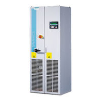
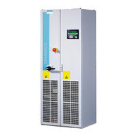
Siemens SINAMICS G130 Manual (1843 pages)
drive converter chassis
Brand:
Siemens
| Category:
Media Converter
| Size: 8.81 MB
Table of Contents
Contents
3
Function Diagrams
3
Qualified Personnel
4
Warning Notice System
4
Additional Information
5
SINAMICS Documentation
5
Faults and Alarms
6
Target Group
6
Usage Phases and Their Tools/Documents
6
SINAMICS G130/G150 List Manual (LH2), 04/2014, A5E03263479A
7
Standard Scope
7
Search Guides
7
Table of Contents
9
Fundamental Safety Instructions
11
General Safety Instructions
12
Parameters
12
1 Fundamental Safety Instructions
13
Industrial Security
13
2 Parameters
15
Overview of Parameters
16
Explanation of the Parameter List
16
Basic Structure of the Parameter Descriptions
16
Parameter Number
17
Full Parameter Name / Abbreviated Name
18
Drive Object (Function Module)
18
Data in the "Drive Object (Function Module)" Field
19
Can be Changed
21
Calculated
22
Access Level
22
Data Type
23
Possible Combinations of BICO Interconnections
23
Dynamic Index
24
Function Diagram
24
P-Group (Only When Accessing Via BOP (Basic Operator Panel))
24
Unit, Unit Group and Unit Selection
24
Parameter Values
27
Not for Motor Type
28
Scaling
28
Expert List
28
Bit Field
29
Dependency
29
Safety Guidelines
29
Number Ranges of Parameters
30
Number Ranges for SINAMICS
30
List of Parameters
33
Infeed Operating Display / INF Op_Display
33
Control Unit Operating Display / CU Op_Display
33
Encoder DO Operating Display / Enc DO Op_Display
34
DRIVE-Cliq Hub Module Operating Display / Hub Op_Display
34
TB30 Operating Display / TB30 Op_Display
34
TM150 Operating Display / TM150 Op_Display
35
TM31 Operating Display / TM31 Op_Display
35
TM54F Operating Display / TM54F Op_Display
35
Drive Operating Display / Drv Op_Display
36
BOP Access Level / BOP Acc_Level
36
BOP Display Filter / BOP Disp_Filter
37
BOP Operating Display Selection / BOP Op_Disp Sel
38
BOP Operating Display Mode / BOP Op_ Disp Mode
38
BOP Background Lighting / BOP Lighting
39
BOP Drive Object after Booting / BOP DO after Boot
39
Device Commissioning Parameter Filter / Dev Comm Par_Filt
39
Infeed Commissioning Parameter Filter / INF Comm Par_Filt
41
Encoder DO Commissioning Parameter Filter / Encdo Com Par_Filt
41
TB30 Commissioning Parameter Filter / TB30 Comm.par_Filt
41
TM150 Commissioning Parameter Filter / TM150 Com Par_Filt
42
TM31 Commissioning Parameter Filter / TM31 Comm Par_Filt
42
TM54F Commissioning Parameter Filter / TM54F Com Par_Filt
42
Drive Commissioning Parameter Filter / Drv Comm. Par_Filt
43
BOP Password Entry (P0013) / BOP Passw Ent P13
43
BOP Password Acknowledgement (P0013) / BOP Passw Ackn P13
43
BOP User-Defined List / BOP List
44
Macro Drive Object / Macro DO
44
Macro Drive Unit / Macro Drv Unit
45
Activate BOP User-Defined List / BOP User List Act
45
Control Unit Firmware Version / CU FW Version
45
CO/BO: Control Word BOP / STW BOP
46
Speed Setpoint Smoothed / N_Set Smth
46
CO: Actual Speed Smoothed / N_Act Smooth
46
Speed Actual Value Rpm Smoothed / N_Act Rpm Smooth
47
Output Frequency Smoothed / F_Outp Smooth
47
CO: Output Voltage Smoothed / U_Outp Smooth
47
CO: DC Link Voltage Smoothed / VDC Smooth
48
CO: Absolute Actual Current Smoothed / I_Act Abs Val Smth
48
Modulation Depth Smoothed / Mod_Depth Smth
49
Current Actual Value Field-Generating Smoothed / Id_Act Smooth
49
Current Actual Value Torque-Generating Smoothed / Iq_Act Smooth
50
Actual Torque Smoothed / M_Act Smooth
50
CO: Active Power Actual Value Smoothed / P_Actv_Act Smth
50
Torque Utilization Smoothed / M_Util Smooth
51
CO: Motor Utilization Thermal / Mot_Util Therm
51
CO: Temperature Input / Temp_Input
52
CO: Motor Temperature / Mot Temp
52
CO: Power Unit Overload I2T / PU Overload I2T
53
CO: Power Unit Temperatures / PU Temperatures
53
Control Unit Temperature / CU Temp
54
Power Factor Smoothed / Cos Phi Smooth
54
Energy Display / Energy Displ
54
Reset Energy Consumption Display / Energy Usage Reset
55
Energy Consumption Saved / Energy Cons Saved
55
Display Values Smoothing Time Constant / Disp_Val T_Smooth
55
CO/BO: Missing Enable Sig / Missing Enable Sig
55
CO/BO: Command Data Set CDS Effective / CDS Effective
59
CO/BO: Drive Data Set DDS Effective / DDS Effective
59
CO/BO: Status Word, Closed-Loop Control / ZSW Cl-Loop Ctrl
59
CO: Speed Setpoint before the Setpoint Filter / N_Set before Filt.
60
CO: Actual Speed Unsmoothed / N_Act Unsmoothed
60
CO: Actual Velocity Unsmoothed / V_Act Unsmoothed
60
CO: Speed Setpoint after the Filter / N_Set after Filter
61
CO: Speed Actual Value / N_Act
61
CO: Speed Controller System Deviation / N_Ctrl System Dev
61
Slip Frequency / F_Slip
62
CO: Output Frequency / F_Outp
62
CO: Output Current Maximum / I_Outp Max
62
CO: DC Current in the DC Link / IDC DC Link
62
CO: Absolute Current Actual Value / I_Act Abs Val
63
CO: Phase Current Actual Value / I_Phase Act Value
63
CO: Actual DC Link Voltage / VDC Act Val
63
Maximum Output Voltage / U_Output Max
64
CO: Output Voltage / U_Output
64
Maximum Modulation Depth / Modulat_Depth Max
64
CO: Modulat_Depth / Modulat_Depth
65
CO: Current Setpoint Field-Generating / Id_Set
65
CO: Current Actual Value Field-Generating / Id_Act
65
CO: Current Setpoint Torque-Generating / Iq_Set
65
CO: Current Actual Value Torque-Generating / Iq_Act
66
CO: Torque Setpoint / M_Set
66
CO: Torque Actual Value / M_Act
66
CO: Torque Utilization / M_Utilization
66
CO: Active Power Actual Value / P_Act
67
CO: Flux Setpoint / Flex Setp
67
CO: Flux Actual Value / Flux Act Val
67
CO: Actual Power Factor / Cos Phi Act
68
CO: DC Link Voltage Setpoint / VDC Setpoint
68
Actual Phase Voltage / U_Phase Act Val
68
Clock Synchronous Operation Pre-Assignment/Check / Cl Sync Op Pre-As
68
CO: Transformation Angle / Transformat_Angle
69
Select Drive Object Type / Select DO Type
69
Actual Device Topology / Device_Act Topo
70
Device Target Topology / Device_Target Topo
70
IEC/NEMA Mot Stds / IEC/NEMA Mot Stds
71
Drive Object Numbers / DO Numbers
71
Number of Drive Objects / DO Count
71
Application-Specific View / Appl_Spec View
72
Activate/De-Activate Drive Object / DO Act/Deact
72
Drive Object Type / DO Type
75
Drive Objects Function Module / DO Fct_Mod
77
Basic Sampling Times / T_Basis
79
Basic Sampling Time Selection / T_Basis Sel
79
Sampling Times Pre-Setting P0115 / T_Sample for P0115
80
Minimum Pulse Frequency, Selection / F_Puls Min Sel
82
Minimum Pulse Frequency Recommended / F_Puls Min Recom
82
Sampling Times for Internal Control Loops / T_Sample Int Ctrl
83
Sampling Time for Speed Detection / T_Sample N_Det
84
Sampling Time for Supplementary Functions / T_Samp Suppl_Fct
84
Drive Object Clock Cycle Recommended / Do_Clock Recom
85
Current Controller Computing Dead Time Mode / I_Ctrl T_Dead Mode
86
Current Controller Computing Dead Time / I_Ctrl T_Dead
86
Number of Power Unit Data Sets (PDS) / PDS Count
86
Power Unit Component Number / PU Comp_No
87
Power Unit Detection Via LED / PU Detection LED
87
Main Component Detection Using LED / M_Comp Detect LED
87
Activate/De-Activate Power Unit Components / Pu_Comp Act/Deact
87
Power Unit Components Active/Inactive / PU Comp Act/Inact
88
Power Unit EEPROM Data Version / PU EEPROM Version
88
Power Unit Firmware Version / PU FW Version
88
Number of Motor Data Sets (MDS) / MDS Count
89
Motor Component Number / Mot Comp_No
89
Motor Configuration / Motor Config
89
Copy Motor Data Set MDS / Copy MDS
89
Number of Encoder Data Sets (EDS) / EDS Count
90
Encoder Component Number / Encoder Comp_No
90
Sensor Module Detection Via LED / SM Detection LED
91
Activate/De-Activate Encoder Interface / Enc_Intf Act/Deact
91
Encoder Interface Active/Inactive / Enc_Intf Act/Inact
91
Sensor Module EEPROM Data Version / SM EEPROM Version
92
Sensor Module Firmware Version / SM FW Version
92
Number of VSM Data Sets / VSM Dat_Sets Qty.
92
DRIVE-Cliq Hub Module Component Number / Hub Comp_No
92
Terminal Module Component Number / TM Comp_No
93
Voltage Sensing Module Component Number / VSM Comp_No
93
DRIVE-Cliq Hub Module Detection Via LED / Hub Detection LED
93
Terminal Module Detection Via LED / TM Detection LED
93
Voltage Sensing Module Active/Inactive / VSM Act/Inact
94
DRIVE-Cliq Hub Module EEPROM Data Version / Hub EEPROM Version
94
Terminal Module EEPROM Data Version / TM EEPROM Version
94
Voltage Sensing Module EEPROM Data Version / VSM EEPROM Version
94
DRIVE-Cliq Hub Module Firmware Version / Hub FW Version
95
Terminal Module Firmware Version / TM FW Version
95
Voltage Sensing Module Firmware Version / VSM FW Version
95
Option Board Component Number / Opt Board Comp_No
95
Number of Command Data Sets (CDS) / CDS Count
96
Number of Drive Data Sets (DDS) / DDS Count
96
Motor Data Sets (MDS) Number / MDS Number
96
Encoder 1 Encoder Data Set Number / Enc 1 EDS Number
96
Encoder 2 Encoder Data Set Number / Enc 2 EDS Number
97
Encoder 3 Encoder Data Set Number / Enc 3 EDS Number
97
Power Unit Firmware Properties 1 / PU FW Property 1
97
Power Unit Firmware Properties 2 / PU FW Property 2
98
VSM Properties / VSM Properties
98
Topology Component Status / Top Comp Stat
99
Bootloader Version / Bootloader Vers
99
BIOS/EEPROM Data Version / BIOS/EEPROM Vers
100
Drive Object Name / DO Name
100
Power Unit Code Number Actual / PU Code No. Act
100
Power Unit Code Number / PU Code no
100
Actual Power Unit Type / PU Actual Type
101
Firmware Package Name / FW Pkg Name
102
Power Unit Hardware Properties / PU HW Property
102
Power Unit Application / PU Application
103
Rated Power Unit Power / PU P_Rated
103
Rated Power Unit Current / PU Pi_Rated
104
Rated Power Unit Line Supply Voltage / PU U_Rated
104
Power Unit Maximum Current / PU I_Max
104
Drive Unit Line Supply Voltage / V_Connect
105
Power Unit Configuration / PU Config
106
Drive Filter Type Motor Side / Drv Filt Type Mot
107
Power Unit Motor Reactor / PU Mot Reactor
108
Power Unit Sine-Wave Filter Capacitance / PU Sine Filter C
109
Motor Reactor in Series Number / L_Mot in Seriesqty
109
Internal Power Unit Resistance / PU R Internal
109
Voltage Measurement Configuration / U_Mes Config
109
Power Unit Cooling Type / PU Cool Type
110
Operating Hours Counter Power Unit Fan / PU Fan T_Oper
110
Maximum Operating Time Power Unit Fan / PU Fan T_Oper Max
110
Power Unit Contactor Monitoring Time / PU Cont T_Monit
111
CO/BO: Power Unit Contactor Inputs/Outputs Status / PU Contact IO Stat
111
Cooling Unit Starting Time 1 / RKA Start Time 1
113
Cooling Unit Fault Conductivity Delay Time / RKA Cond T_Del
113
Cooling Unit Fault Liquid Flow Delay Time / RKA Flow T_Del
113
Cooling Unit Run-On Time / RKA Run-On Time
114
BO: Cooling Unit Control Word / RKA STW
114
BI: Cooling Unit Feedback Signals Signal Source / RKA Fdbk S_Src
114
BO: Cooling Unit Status Word / RKA ZSW
114
DC Link Voltage Undervoltage Threshold Reduction / VDC U_Under Red
115
DC Link Voltage Offset Alarm Threshold / VDC Offs a Thresh
115
Ground Fault Monitoring Thresholds / Gnd Flt Threshold
115
CO: Maximum Power Unit Output Current / PU I_Outp Max
116
Power Unit Overload Response / PU Overld Response
116
CO: Power Unit Alarm Threshold Model Temperature / PU A_Thr Mod_Temp
117
Power Unit Alarm with I2T Overload / PU I2T Alrm Thresh
117
Fan Run-On Time / Fan Run-On Time
117
DC Link Voltage Undervoltage Threshold / VDC U_Lower_Thresh
118
DC Link Voltage Overvoltage Threshold / VDC U_Upper_Thresh
118
Motor Type Selection / Mot Type Sel
118
Motor Code Number Selection / Mot Code No. Sel
120
Motor Code Number of Motor with DRIVE-Cliq / Mot Code Mot W/ DQ
120
Motor with DRIVE-Cliq Status Word / Motor W DQ ZSW
121
Rated Motor Voltage / Mot U_Rated
121
Rated Motor Current / Mot I_Rated
121
Number of Motors Connected in Parallel / Motor Qty
122
Rated Motor Power / Mot P_Rated
122
Rated Motor Power Factor / Mot Cos Phi Rated
123
Rated Motor Efficiency / Mot Eta_Rated
123
Rated Motor Frequency / Mot F_Rated
123
Rated Motor Speed / Mot N_Rated
124
Motor Pole Pair Number, Actual (or Calculated) / Mot Polepairno Act
124
Motor Pole Pair Number / Mot Pole Pair No.
124
Motor Torque Constant / Mot Kt
125
Motor Stall Current / Mot I_Standstill
125
Maximum Motor Speed / Mot N_Max
126
Maximum Motor Current / Mot I_Max
126
Winding Maximum Speed / Winding N_Max
126
Optimum Motor Load Angle / Mot Phi_Load Opt
127
Motor Reluctance Torque Constant / Mot Kt_Reluctance
127
Motor Pole Position Identification Current / Mot Polid Current
128
Rated Motor Torque / Mot M_Rated
129
Actual Motor-Torque Constant / Mot Kt Act
129
Motor Cooling Type / Mot Cool Type
129
Actual Rated Motor Frequency / Mot F_Rated Act
130
Rated Motor EMF / Mot Emf_Rated
130
Automatic Calculation Motor/Control Parameters / Calc Auto Par
130
Motor Moment of Inertia / Mot M_Mom of Inert
132
Rated Motor Current Identified / Mot I_Rated Ident
133
Motor Weight (for the Thermal Motor Model) / Mot Weight Th Mod
133
Nominal Motor Starting Time / Mot T_Start_Rated
133
Motor Excitation Build-Up Time / Mot T_Excitation
133
Motor De-Excitation Time / Mot T_De-Excitat
134
Motor Stator Resistance Cold / Mot R_Stator Cold
134
Cable Resistance / R_Cable
135
Motor Series Inductance / Mot L_Series
135
Motor Damping Resistance Q Axis / Mot R_Damp Q
136
Motor Stator Leakage Inductance / Mot L_Stator Leak.
136
Motor Stator Inductance D Axis / Mot L_Stator D
136
Motor Damping Inductance Q Axis / Mot L_Damp Q
137
Motor Magnetizing Inductance Q Axis Saturated / Mot L_Magn Q Sat
137
Motor Saturation Characteristic Flux 1 / Mot Saturat.flux 1
138
Motor Saturation Characteristic Flux 2 / Mot Saturat.flux 2
138
Motor Saturation Characteristic Flux 3 / Mot Saturat.flux 3
139
Motor Saturation Characteristic Flux 4 / Mot Saturat.flux 4
140
Motor Saturation Characteristic I_Mag 1 / Mot Sat. I_Mag 1
140
Motor Saturation Characteristic I_Mag 2 / Mot Sat. I_Mag 2
141
Motor Saturation Characteristic I_Mag 3 / Mot Sat. I_Mag 3
141
Motor Saturation Characteristic I_Mag 4 / Mot Sat. I_Mag 4
142
Cable Resistance / Mot R_Cable
143
Motor Rated Stator Resistance / Mot R_Stator Rated
143
Rated Motor Rotor Resistance / Mot Rated R_Rotor
143
Motor Damping Time Constant Q Axis / Mot L_Damping Q
145
Motor Stator Leakage Time Constant / Mot T_Stator Leak
146
Motor Stator Leakage Time Constant Q Axis / Mot T_Sleak /T_Sq
146
Excitation Rated No-Load Current / Exc I_Noload_Rated
146
Rated Excitation Current / Exc I_Rated
146
Current Controller Adaptation P Gain Scaling / I_Adapt Kp Scal
147
Actual Stator Resistance / R_Stator Act
147
Actual Rotor Resistance / R_Rotor Act
148
Angle Magnetic Decoupling Maximum Angle / Magn Decpl Max_Ang
148
Angle Magn Decoupling (Cross Saturation) Coeff 1 / Magn Decoupl C1
148
Angle Magn Decoupling (Cross Saturation) Coeff 3 / Magn Decoupl C3
148
Encoder Type Selection / Enc_Typ Sel
149
Encoder Type OEM Selection / Enc Type OEM Sel
151
Gearbox Type Selection / Gearbox Type Sel
151
Encoder Configuration Effective / Enc_Config Eff
152
Square-Wave Encoder Track A/B / Sq-Wave Enc A/B
154
Linear Encoder Grid Division / Enc Grid DIV
154
Rotary Encoder Pulse Number / Rot Enc Pulse No.
155
Encoder Inversion Actual Value / Enc Inv Act Value
155
Measuring Gear Configuration / Meas Gear Config
156
Measuring Gear Position Tracking Tolerance Window / Pos Track Window
157
Encoder Safety Comparison Algorithm (Detected) / Safety Comp_Algo
158
Fine Resolution Gx_Xist1 (in Bits) / Enc Fine Gx_Xist1
158
Fine Resolution Absolute Value Gx_Xist2 (in Bits) / Enc Fine Gx_Xist2
158
Encoder Connection / Enc_Connection
158
Absolute Encoder Rotary Multiturn Resolution / Enc Abs Multiturn
159
Absolute Encoder Linear Measuring Step Resolution / Enc Abs Meas Step
159
Absolute Encoder Rotary Singleturn Resolution / Enc Abs Singleturn
159
Encoder Linear Zero Mark Distance / Enc Lin Zm_Dist
159
Encoder Rotary Zero Mark Distance / Enc Rot Dist ZM
160
Encoder Zero Mark Differential Distance / Enc ZM Dif_Dist
160
Encoder SSI Baud Rate / Enc SSI Baud Rate
160
Encoder SSI Monoflop Time / Enc SSI T_Monoflop
160
Encoder SSI Configuration / Enc SSI Config
161
Sensor Module Configuration / SM Config
161
Angular Commutation Offset / Ang_Com Offset
163
Gearbox Factor Encoder Revolutions / Grbx_Fact Enc_Rev
164
Gearbox Factor Motor/Load Revolutions / Grbx_Fact Mot_Rev
164
Encoder SSI Error Bit / Enc SSI Error Bit
164
Encoder SSI Alarm Bit / Enc SSI Alarm Bit
165
Encoder SSI Parity Bit / Enc SSI Parity Bit
165
Sensor Module Configuration Extended / SM Config Ext
165
Squarewave Encoder Filter Time / Enc T_Filt
168
Encoder Ramp-Up Time / Enc Ramp-Up Time
168
Copy Encoder Serial Number / Copy Enc Ser_No
168
Encoder Commissioning Serial Number Part 1 / Enc Comm Ser_No 1
169
Encoder Commissioning Serial Number Part 2 / Enc Comm Ser_No 2
169
Encoder Commissioning Serial Number Part 3 / Enc Comm Ser_No 3
169
Encoder Commissioning Serial Number Part 4 / Enc Comm Ser_No 4
169
Encoder SSI Number of Bits Absolute Value / Enc SSI Bit Val
170
Encoder SSI Number of Bits Filler Bits / Enc SSI Fill Bits
171
Commutation Angle Factor / Enc Commut_Factor
171
Squarewave Encoder Filter Time Display / Enc T_Filt Displ
171
Pulse Encoder Evaluation Zero Speed Measuring Time / Enc_Ev N_0 T_Meas
172
Encoder Configuration Recognized / Enc Config Act
172
Encoder Configuration Supported / Enc_Config Supp
173
Sensor Module Properties / SM Properties
175
Sensor Module Properties Extended / SM Prop Ext
178
Encoder Serial Number Part 1 / Enc Ser_No 1
180
Encoder Serial Number Part 2 / Enc Ser_No 2
181
Encoder Serial Number Part 3 / Enc Ser_No 3
181
Encoder Serial Number Part 4 / Enc Ser_No 4
182
Encoder 1 Identification Number/Serial Number / Enc1 Id_No/Ser_No
183
Encoder 2 Identification Number/Serial Number / Enc2 Id_No/Ser_No
183
Encoder 3 Identification Number/Serial Number / Enc3 Id_No/Ser_No
183
Absolute Encoder Linear Measuring Step / Enc Lin Meas Step
184
Redundant Coarse Position Value Valid Bits / Valid Bits
184
Redundant Coarse Position Value Fine Resolution Bits / Fine Bit
185
Redundant Coarse Position Value Relevant Bits / Relevant Bits
185
Non Safety-Relevant Measuring Steps Position Value Pos1 / Nsrpos1
185
Redundant Coarse Position Value Configuration / Red Pos Config
186
Gx_Xist1 Coarse Position Safe most Significant Bit / Gx_Xist1 Safe MSB
187
CO: Measuring Gear Position Difference / Meas Gear Pos Diff
187
CO: Diagnostics Encoder Position Actual Value Gn_Xist1 / Diag Gn_Xist1
188
CI: Encoder Control Word Gn_Stw Signal Source / Enc Gn_Stw S_Src
188
CO: Encoder Status Word Gn_Zsw / Enc Gn_Zsw
189
CO: Encoder Actual Position Value Gn_Xist1 / Enc Gn_Xist1
190
CO: Encoder Actual Position Value Gn_Xist2 / Enc Gn_Xist2
191
CO: Redundant Coarse Encoder Position + CRC / Enc Red Pos+Crc
192
CO: Measuring Gear Encoder Raw Value Incremental / Enc Raw Val Incr
193
CO: Measuring Gear Encoder Raw Value Absolute / Enc Raw Val Abs
194
Diagnostic Encoder Control Word Gn_Stw / Enc Gn_Stw
194
Measuring Probe 1 Input Terminal / Meas Probe 1 Inp
195
Measuring Probe 2 Input Terminal / Meas Probe 2 Inp
196
Motor Encoder Fault Response ENCODER / Fault Resp ENCODER
197
Square-Wave Encoder Maximum Speed Difference Per Sampling Cycle
198
Square-Wave Encoder Max. Velocity Difference Per Sampling Cycle
198
Maximum Speed Difference Per Sampling Cycle / N_Dif Max/Samp_Cyc
198
Zero Mark Selection Input Terminal / Zm_Sel Inp_Term
199
Equivalent Zero Mark Input Terminal / Zm_Equiv Inp_Term
200
Equivalent Zero Mark Input Terminal / Zm_Equiv Input
200
Encoder Diagnostic Signal Selection / Enc Diag Select
202
Encoder Diagnostic Signal Double Word / Enc Diag DW
205
CO: Encoder Diagnostic Signal Double Word / Enc Diag DW
205
Encoder Diagnostic Signal Low Word / Enc Diag Low Word
205
CO: Encoder Diagnostic Signal Low Word / Enc Diag Low Word
205
Encoder Diagnostic Signal High Word / Enc Diag High Word
206
CO: Encoder Diagnostic Signal High Word / Enc Diag High Word
206
Technology Application / Tec Application
206
Selecting the System of Units / Unit Sys Select
207
User-Specific Reference Quantities / Usrdef_Ref
207
Assignment Parameter 1 in Reference to P514[0] / Bicolist1_Ref1
208
Assignment Parameter 2 in Reference to P514[1] / Bicolist2_Ref2
208
Assignment Parameter 3 in Reference to P514[2] / Bicolist3_Ref3
208
Assignment Parameter 4 in Reference to P514[3] / Bicolist4_Ref4
209
Assignment Parameter 5 in Reference to P514[4] / Bicolist5_Ref5
209
Assignment Parameter 6 in Reference to P514[5] / Bicolist6_Ref6
209
Assignment Parameter 7 in Reference to P514[6] / Bicolist7_Ref7
210
Assignment Parameter 8 in Reference to P514[7] / Bicolist8_Ref8
210
Assignment Parameter 9 in Reference to P514[8] / Bicolist9_Ref9
210
Assignment Parameter 10 in Reference to P514[9] / Bicolist10_Ref10
211
Controller Gain System of Units / Ctrl_Gain Unit_Sys
211
Bearing Version Selection / Bearing Vers Sel
212
Bearing Code Number Selection / Bearing Codeno Sel
212
Bearing Maximum Speed / Bearing N_Max
212
CO: Probe Time Stamp / Probe T_Stamp
213
CO: Probe Time Stamp Reference / Probe T_Stamp Name
213
CO: Probe Diagnostics Word / Probe Diag_Word
213
Inhibit List Values Effective Number / Inhib List no
213
Activate/De-Activate Inhibit List / Inh_List Act/Deact
214
Inhibit Automatic Reference Value Calculation / Inhibit Calc
214
Calculate Technology-Dependent Parameters / Calc Tec Par
215
Technological Unit Selection / Tech Unit Select
215
Technological Unit Reference Quantity / Tech Unit Ref Qty
216
Motor Temperature Sensor for Monitoring / Mot Temp_Sensor
216
Temperature Sensor, Sensor Type / Temp_Sens Type
217
Motor Temperature Sensor Type / Mot_Temp_Sens Type
217
Par_Circuit Power Unit Number, Temperature Sensor / Pu_No Temp_Sensor
218
CI: Motor Temperature Signal Source / Mot Temp S_Src
218
Mot_Temp_Mod 2/KTY Alarm Threshold / Mod 2/KTY a Thresh
219
Mot_Temp_Mod 1/2 Threshold / Mod 1/2 Threshold
219
Mot_Temp_Mod 2/KTY Timer / Mod 2/KTY T_Timer
219
Temperature Sensor Fault Timer / Sensor Fault Time
220
CI: Motor Temperature Signal Source 2 / Mot_Temp S_Src 2
220
CI: Motor Temperature Signal Source 3 / Mot_Temp S_Src 3
221
Motor Overtemperature Response / Mot Temp Response
221
I2T Motor Model Thermal Time Constant / I2T Mot_Mod T
222
Mot_Temp_Mod Activation / Mot_Temp_Mod Act
222
Thermal Resistance Adaptation Reduction Factor / Therm R_Adapt Red
223
Mot_Temp_Mod 1 (I2T) Fault Threshold / I2T F Thresh
223
Motor Overtemperature Alarm Threshold 1 / Mot Temp Alarm 1
223
Thermal Adaptation, Stator and Rotor Resistance / Mot Therm_Adapt R
223
Identification Stator Resistance after Restart / Rst_Ident Restart
224
Motor Temperature Offset PT100 / Mot T_Offset PT100
225
Motor Ambient Temperature During Commissioning / Mot T_Ambient
225
Motor Overtemperature, Stator Core / Mot T_Over Core
226
Motor Overtemperature, Stator Winding / Mot T_Over Stator
226
Motor Overtemperature Rotor Winding / Mot T_Over Rotor
226
Stator Resistance Reference / R_Stator Ref
227
Mot_Temp_Mod Ambient Temperature / Mod T_Ambient
227
Mot_Temp_Mod Stator Iron Temperature / Mod T_Stator
227
Mot_Temp_Mod Stator Winding Temperature / Mod T_Winding
227
Mot_Temp_Mod Rotor Temperature / Mod Rotor Temp
228
Q Flux Flux Constant Unsaturated / PSIQ KPSI UNSAT
228
Q Flux Quadrature Axis Current Constant Unsaturated / PSIQ KIQ UNSAT
228
Q Flux Direct Axis Current Constant Unsaturated / PSIQ KID UNSAT
228
Current Limit / Current Limit
229
CI: Current Limit Variable / Curr Lim Var
229
Overvoltage Protection for Synchronous Motors / Overvolt_Protect
229
Current Limit Excitation Induction Motor / Imax Excitat ASM
230
Actual Motor Operating Hours / Mot T_Oper Act
230
Motor Operating Hours Maintenance Interval / Mot T_Op Maint
230
Motor Stator Resistance Scaling / Mot R_Stator Scal
231
Motor Stator Leakage Inductance Scaling / Mot L_S_Leak Scal
231
Motor Damping Inductance D Axis Scaling / Mot L_Damp D Scal
231
Motor Damping Inductance Q Axis Scaling / Mot L_Damp Q Scal
232
Motor Damping Resistance D Axis Scaling / Mot R_Damp D Scal
232
Motor Damping Resistance Q Axis Scaling / Mot R_Damp Q Scal
232
Central Measuring Probe Input Terminal / Cen Meas Inp
232
Central Measuring Probe Evaluation Technique / Cen Meas Eval_Tech
233
Central Measuring Probe Control Word Display / Cen Meas STW Disp
234
CO: Central Measuring Probe Status Word Display / Cen Meas ZSW Disp
235
Macro Binector Input (BI) / Macro BI
235
Macro Binector Input (BI) for Tms / Macro BI TM
236
CU Digital Inputs Terminal Actual Value / CU DI Term Act Val
236
CO/BO: CU Digital Inputs Status / CU DI Status
237
CO/BO: CU Digital Inputs Status Inverted / CU DI Status Inv
238
CU Set Input or Output / CU DI or DO
238
CU Digital Outputs Access Authority / CU DO Acc_Auth
239
BI: CU Signal Source for Terminal DI/DO 8 / CU S_Src DI/DO 8
239
BI: CU Signal Source for Terminal DI/DO 9 / CU S_Src DI/DO 9
239
BI: CU Signal Source for Terminal DI/DO 10 / CU S_Src DI/DO 10
240
BI: CU Signal Source for Terminal DI/DO 11 / CU S_Src DI/DO 11
240
BI: CU Signal Source for Terminal DI/DO 12 / CU S_Src DI/DO 12
240
BI: CU Signal Source for Terminal DI/DO 13 / CU S_Src DI/DO 13
240
BI: CU Signal Source for Terminal DI/DO 14 / CU S_Src DI/DO 14
241
BI: CU Signal Source for Terminal DI/DO 15 / CU S_Src DI/DO 15
241
CU Digital Outputs Status / CU DO Status
241
CU Invert Digital Outputs / CU DO Inv
242
CI: Test Sockets Signal Source / Test Skt S_Src
242
Test Sockets Output Signal / Testsktssignalval
242
Test Sockets Output Voltage / Testskts U_Output
243
Test Socket Mode / Test Skt Mode
243
Test Socket Characteristic Value X1 / Test Skt Char X1
243
Test Socket Characteristic Value Y1 / Test Skt Char Y1
244
Test Socket Characteristic Value X2 / Test Skt Char X2
244
Test Socket Characteristic Value Y2 / Test Skt Char Y2
244
Test Sockets Offset / Test Skt Offset
245
Test Socket Limit On/Off / Testsktlim On/Off
245
Test Socket Scaling Per Volt / Testsktscale/Volt
245
Test Sockets Physical Address / Test Skt Phyaddr
246
Test Sockets Physical Address Gain / Testsktphyaddrgain
246
Test Sockets Physical Address Signal Value / Testsktsphyaddrval
246
CU Digital Inputs Simulation Mode / CU DI Simulation
246
CU Digital Inputs Simulation Mode Setpoint / CU DI Simul Setp
247
CU Inputs/Outputs Sampling Time / CU I/O T_Sampl
248
BI: Inhibit Master Control / Pcctrl Inhibit
248
BO: Master Control Active / Pcctrl Active
248
Copy Command Data Set CDS / Copy CDS
249
BI: Command Data Set Selection CDS Bit 0 / CDS Select., Bit 0
249
BI: Command Data Set Selection CDS Bit 1 / CDS Select., Bit 1
249
Copy Drive Data Set DDS / Copy DDS
250
BI: Drive Data Set Selection DDS Bit 0 / DDS Select., Bit 0
250
BI: Drive Data Set Selection DDS Bit 1 / DDS Select., Bit 1
250
BI: Drive Data Set Selection DDS Bit 2 / DDS Select., Bit 2
250
BI: Drive Data Set Selection DDS Bit 3 / DDS Select., Bit 3
251
BI: Drive Data Set Selection DDS Bit 4 / DDS Select., Bit 4
251
Motor Changeover Motor Number / Mot_Chng Mot No.
251
Motor Changeover Status Word Bit Number / Mot_Chg ZSW Bitno.
251
BI: Motor Changeover Feedback Signal / Mot_Chng Fdbk Sig
252
CO/BO: Motor Changeover Status Word / Mot_Chngov ZSW
252
BI: Motor Changeover Contactor Feedback / Mot_Chg Cont Fdbk
252
Data Set Changeover Configuration / Ds_Chng Config
254
CO/BO: Data Set Changeover Status Word / DDS_ZSW
254
CO/BO: Command Data Set CDS Selected / CDS Selected
255
CO/BO: Drive Data Set DDS Selected / DDS Selected
255
Motor/Encoder Data Set Selected / MDS/EDS Selected
256
Motor Changeover Contactor Control Delay Time / Mot_Chg Ctrl T_Del
256
Bi: on / off (Off1) / on / off (Off1)
256
BI: no Coast-Down / Coast-Down (OFF2) Signal Source 1 / OFF2 S_Src 1
257
BI: no Coast-Down / Coast-Down (OFF2) Signal Source 2 / OFF2 S_Src 2
258
BI: no Quick Stop / Quick Stop (OFF3) Signal Source 1 / OFF3 S_Src 1
258
BI: no Quick Stop / Quick Stop (OFF3) Signal Source 2 / OFF3 S_Src 2
259
BI: Enable Operation/Inhibit Operation / Operation Enable
259
BI: Control by Plc/No Control by PLC / Master Ctrl by PLC
260
BI: Unconditionally Release Holding Brake / Uncond Open Brake
260
BI: Speed Controller Enable / N_Ctrl Enable
261
Power Unit Monitoring Time / PU T_Monit
261
BI: Unconditionally Close Holding Brake / Uncond Close Brake
261
BI: Line Contactor Feedback Signal / Line Contact Feedb
262
Line Contactor Monitoring Time / Linecontact T_Mon
262
Power Unit on Delay / PU T_On
262
CO/BO: Drive Coupling Status Word/Control Word / Couplezsw/Stw
262
BI: Infeed Operation / INF Operation
263
Power Unit Main Contactor Holding Time after OFF1 / PU T_Mc after OFF1
263
Power Unit DC Switch Debounce Time / PU DC Sw T_Deboun
264
Sequence Control Configuration / Seq_Ctrl Config
264
CO/BO: Infeed Total Operation / INF Total Oper
264
BI: Smart/ Basic Line Module Operation / SLM/BLM Operation
265
Parking Pre-Setting / Parking Pre-Set
265
BI: Activate/De-Activate Power Unit Components / Pu_Comp Act/Deact
265
BO: Parking Axis, Status Word / Parking Axis, ZSW
266
BI: Parking Axis Selection / Parking Axis Sel
266
CO/BO: Control Word Sequence Control Infeed / STW Seq_Ctrl INF
266
CO/BO: Control Word Drive Object 1 / STW DO1
266
CO/BO: Control Word Sequence Control Encoder DO / STW Seq_Ctrl Encdo
267
CO/BO: Control Word Sequence Control / STW Seq_Ctrl
267
CO/BO: Status Word Sequence Control Infeed / ZSW Seq_Ctrl INF
267
CO/BO: Status Word Drive Object 1 / ZSW DO1
268
CO/BO: Status Word Sequence Control Encoder DO / ZSW Seq_Ctrl Encdo
268
CO/BO: Status Word Sequence Control / ZSW Seq_Ctrl
268
PROFIBUS Address / PB Address
269
IF1 Profidrive PZD Telegram Selection / IF1 PZD Telegr
269
ZSW Bit Pulses Enabled / ZSW Pulse Enab
271
Profidrive Clock Synchronous Sign-Of-Life Tolerance / PD Sol_Tol
271
Profidrive Operating Mode / PD Operating Mode
272
CO: Counter for Fault Buffer Changes / Fault Buff Change
272
Fault Code / Fault Code
272
Fault Code List / Fault Code List
273
Fault Number / Fault Number
273
Fault Time Received in Milliseconds / T_Fault Recv Ms
273
Fault Value / Fault Value
273
Fault Cases Counter / Fault Cases Qty
274
PROFIBUS Baud Rate / PB Baud Rate
274
Device Identification / Device Ident
274
Profidrive Profile Number / PD Profile Number
275
System Runtime Relative / T_System Relative
275
Reset Infeed Parameter / INF Par Reset
275
ENCODER Reset Parameters / ENC Par Reset
276
TB30 Reset Parameters / TB30 Par Reset
276
TM150 Reset Parameters / TM150 Par Reset
276
TM31 Reset Parameters / TM31 Par Reset
277
TM54F Reset Parameters / TM54F Par Reset
277
Reset Drive Parameters / Drive Par Reset
277
Save Drive Object Parameters / Drv_Obj Par Save
278
Drive Unit Reset / Drv_Unit Reset
278
Drive Object Identification / DO Identification
279
Reset and Load All Parameters / Reset Load All Par
280
Save All Parameters / Save All Par
280
List of Drive Objects / List of the DO
281
Profidrive Encoder Format / PD Encoder Format
281
List of Existing Parameters 1 / List Avail Par 1
282
List of Existing Parameters 2 / List Avail Par 2
283
List of Existing Parameters 10 / List Avail Par 10
283
List of Modified Parameters 1 / List Chang Par 1
283
List of Modified Parameters 2 / List Chang Par 2
284
List of Modified Parameters 10 / List Chang Par 10
284
Macro Connector Inputs (CI) for Speed Setpoints / Macro CI N_Set
284
CO: Fixed Speed Setpoint 1 / N_Set_Fixed 1
285
CO: Fixed Speed Setpoint 2 / N_Set_Fixed 2
285
CO: Fixed Speed Setpoint 3 / N_Set_Fixed 3
285
CO: Fixed Speed Setpoint 4 / N_Set_Fixed 4
285
CO: Fixed Speed Setpoint 5 / N_Set_Fixed 5
286
CO: Fixed Speed Setpoint 6 / N_Set_Fixed 6
286
CO: Fixed Speed Setpoint 7 / N_Set_Fixed 7
286
CO: Fixed Speed Setpoint 8 / N_Set_Fixed 8
286
CO: Fixed Speed Setpoint 9 / N_Set_Fixed 9
287
CO: Fixed Speed Setpoint 10 / N_Set_Fixed 10
287
CO: Fixed Speed Setpoint 11 / N_Set_Fixed 11
287
CO: Fixed Speed Setpoint 12 / N_Set_Fixed 12
287
CO: Fixed Speed Setpoint 13 / N_Set_Fixed 13
288
CO: Fixed Speed Setpoint 14 / N_Set_Fixed 14
288
CO: Fixed Speed Setpoint 15 / N_Set_Fixed 15
288
BI: Fixed Speed Setpoint Selection Bit 0 / N_Set_Fixed Bit 0
288
BI: Fixed Speed Setpoint Selection Bit 1 / N_Set_Fixed Bit 1
289
BI: Fixed Speed Setpoint Selection Bit 2 / N_Set_Fixed Bit 2
289
BI: Fixed Speed Setpoint Selection Bit 3 / N_Set_Fixed Bit 3
289
CO: Fixed Speed Setpoint Effective / N_Set_Fixed Eff
290
Motorized Potentiometer Configuration / Mop Configuration
290
BI: Motorized Potentiometer Setpoint Raise / Mop Raise
291
BI: Motorized Potentiometer Lower Setpoint / Mop Lower
291
Motorized Potentiometer Maximum Speed / Motp N_Max
291
Motorized Potentiometer Minimum Speed / Motp N_Min
291
BI: Motorized Potentiometer Inversion / Motp Inv
292
Motorized Potentiometer Starting Value / Mop Start Value
292
BI: Motorized Potentiometer Manual/Automatic / Mop Manual/Auto
292
CI: Motorized Potentiometer Automatic Setpoint / Mop Auto Setpoint
292
BI: Motorized Potentiometer Accept Setting Value / Motp Acc Set Val
293
CI: Motorized Potentiometer Setting Value / Mop Set Val
293
CO: Mot. Potentiometer Speed Setp. in Front of Ramp-Fct. Gen.
293
Motorized Potentiometer Ramp-Up Time / Mop Ramp-Up Time
293
CO: Motor. Potentiometer Setpoint after the Ramp-Function Generator
294
CI: Speed Limit RFG Positive Direction of Rotation / N_Limit RFG Pos
294
CI: Speed Limit RFG Negative Direction of Rotation / N_Limit RFG Neg
294
BI: Jog Bit 0 / Jog Bit 0
294
BI: Jog Bit 1 / Jog Bit 1
295
Jog 1 Speed Setpoint / Jog 1 N_Set
295
Jog 2 Speed Setpoint / Jog 2 N_Set
295
Speed Limit Setpoint Channel / N_Limit Setp
295
CI: Main Setpoint / Main Setpoint
296
CI: Main Setpoint Scaling / Main Setp Scal
296
CO: Main Setpoint Effective / Main Setpoint Eff
296
CI: Supplementary Setpoint / Suppl Setp
296
CO: Supplementary Setpoint Effective / Suppl Setpoint Eff
297
CO: Total Setpoint Effective / Total Setpoint Eff
297
Minimum Speed / N_Min
297
Maximum Speed Scaling / N_Max Scal
297
Maximum Speed / N_Max
298
CO: Speed Limit in Positive Direction of Rotation / N_Limit Pos
298
CO: Speed Limit Positive Effective / N_Limit Pos Eff
299
CI: Speed Limit in Positive Direction of Rotation / N_Limit Pos
299
CO: Speed Limit in Negative Direction of Rotation / N_Limit Neg
299
CO: Speed Limit Negative Effective / N_Limit Neg Eff
299
Skip Speed 1 / N_Skip 1
300
Skip Speed 2 / N_Skip 2
300
Skip Speed 3 / N_Skip 3
300
Skip Speed 4 / N_Skip 4
300
CI: Skip Speed Scaling / N_Skip Scal
301
CO/BO: Skip Band Status Word / Skip Band ZSW
301
Skip Speed Bandwidth / N_Skip Bandwidth
301
CI: Minimum Speed Signal Source / N_Min S_Src
302
BI: Inhibit Negative Direction / Inhib Neg dir
302
BI: Inhibit Positive Direction / Inhib Pos dir
302
CO: Speed Setpoint after Minimum Limiting / N_Set Aft Min_Lim
302
CO: Setpoint after the Direction Limiting / Setp after Limit
303
Ramp-Function Generator Selection / RFG Selection
303
CO: Ramp-Function Generator Setpoint at the Input / RFG Setp at Inp
303
Ramp-Function Generator Ramp-Up Time / RFG Ramp-Up Time
303
Ramp-Function Generator Ramp-Down Time / RFG Ramp-Down Time
304
BI: Bypass Ramp-Function Generator / Bypass RFG
304
Ramp-Function Generator Initial Rounding-Off Time / RFG T_Start_Round
304
Ramp-Function Generator Final Rounding-Off Time / RFG T_End_Delay
304
Ramp-Function Generator Rounding-Off Type / RFG Round-Off Type
305
OFF3 Ramp-Down Time / OFF3 T_Rd
305
OFF3 Initial Rounding-Off Time / RFGOFF3 T_Strt_Rnd
305
OFF3 Final Rounding-Off Time / RFG OFF3 T_End_Del
305
CI: Ramp-Function Generator Ramp-Up Time Scaling / RFG T_Ru Scal
306
CI: Ramp-Function Generator Ramp-Down Time Scaling / RFG T_Rd Scal
306
BI: Enable Ramp-Function Generator/Inhibit Ramp-Function Generator
306
BI: Continue Ramp-Function Generator/Freeze Ramp-Function Generator
306
BI: Enable Setpoint/Inhibit Setpoint / Setpoint Enable
307
BI: Ramp-Function Generator, Accept Setting Value / RFG Accept Set V
307
CI: Ramp-Function Generator Setting Value / RFG Setting Value
308
Ramp-Function Generator Tracking Intensity. / RFG Track Intens
308
Ramp-Function Gen. Tolerance for Ramp-Up and Ramp-Down Active
308
CO: Ramp-Function Generator Acceleration / RFG Acceleration
309
CO: Ramp-Function Generator Speed Setpoint at the Output
309
Ramp-Function Generator Configuration / RFG Config
309
BI: Setpoint 2 Enable / Setp 2 Enab
310
CI: Speed Controller Speed Setpoint 1 / N_Ctrl N_Set 1
310
CI: Speed Controller Speed Setpoint 2 / N_Ctrl N_Set 2
310
CO: Speed Controller Speed Setpoints 1 and 2 / N_Ctrl N_Set 1/2
310
CO: Speed Controller Setpoint Sum / N_Ctrl Setp Sum
311
Speed Setpoint Configuration / N_Ctrl Config
311
Fixed Speed Setpoint Number Actual / N_Set_Fixed no Act
311
CO/BO: Control Word Setpoint Channel / STW Setpoint Chan
311
CO/BO: Ramp-Function Generator Status Word / RFG ZSW
312
Flying Restart Operating Mode / Flyrest Op_Mode
312
BI: Flying Restart Enable Signal Source / Fly_Res Enab S_Src
313
Flying Restart Search Current / Flyrest I_Srch
313
Flying Restart Search Rate Factor / Flyrst V_Srch Fact
314
CO/BO: Flying Restart U/F Control Status / Flyrest Uf St
314
CO/BO: Flying Restart Vector Control Status / Flyrest Vector St
314
Faults Without Automatic Restart / F W/Out Auto AR
315
BI: AR Connection Following Drive Object / AR Connection DO
315
BI: AR Modification Infeed / AR Modification
316
Automatic Restart Mode / AR Mode
316
Automatic Restart Start Attempts / AR Start Attempts
317
Automatic Restart Delay Time Start Attempts / AR T_Wait Start
319
Automatic Restart Monitoring Time / AR T_Monit
319
CO/BO: Automatic Restart Status / AR Status
320
Motor Holding Brake Configuration / Brake Config
322
Motor Holding Brake Opening Time / Brake T_Open
323
Motor Holding Brake Closing Time / Brake T_Close
323
BI: Open Motor Holding Brake / Open Brake
323
BI: Immediately Close Motor Holding Brake / Close Brake
324
CI: Open Motor Holding Brake Signal Source Threshold
324
Open Motor Holding Brake Threshold / Open Brake Thresh
324
BI: Motor Holding Brake Feedback Signal Brake Closed
324
BI: Motor Holding Brake Feedback Signal Brake Open / Brake Feedb Open
325
BI: Close Motor Holding Brake at Standstill / Brk Close Standst
325
CI: Standstill Detection Threshold Value / Standstill Thresh
325
Threshold for Zero Speed Detection / N_Standst N_Thresh
325
Zero Speed Detection Monitoring Time / N_Standst T_Monit
326
Pulse Suppression Delay Time / Pulse Suppr T_Del
326
CO/BO: Motor Holding Brake Status Word / Brake ZSW
327
BI: Armature Short-Circuit / DC Braking Activation / ASC/DCBRK Act
327
Armature Short-Circuit / DC Braking Configuration / ASC/DCBRK Config
327
DC Braking Braking Current / DCBRK I_Brake
329
DC Braking Time / DCBRK Time
329
Speed at the Start of DC Braking / DCBRK N_Start
330
BI: External Armature Short-Circuit Contactor Feedback Signal
330
Ext. Armature Short-Cct. Contactor Feedback Signal Monit. Time
330
External Armature Short-Circuit Delay Time When Opening
330
CO: Armature Short-Circuit External State / EASC State
331
CO/BO: Armature Short-Circuit / DC Braking Status Word / ASC/DCBRK ZSW
332
VDC Controller or VDC Monitoring Configuration / VDC Ctrl Config
333
Vdc_Max Controller Switch-In Level / Vdc_Max On_Level
334
Vdc_Max Controller Dynamic Factor / Vdc_Max Dyn_Factor
334
Vdc_Min Controller Switch-In Level (Kinetic Buffering)
334
Vdc_Max Controller Speed Threshold / Vdc_Max N_Thresh
335
VDC Controller Proportional Gain / Vdc_Ctrl Kp
335
VDC Controller Integral Time / Vdc_Ctrl Tn
336
VDC Controller Rate Time / Vdc_Ctrl T_Rate
336
Vdc_Max Controller Automatic on Level Detection / Vdc_Max Senseonlev
336
Vdc_Min Controller Time Threshold / Vdc_Min T_Thresh
336
Vdc_Min Controller Response (Kinetic Buffering) / Vdc_Min Response
337
Vdc_Min Controller Speed Threshold / Vdc_Min N_Thresh
337
CO: VDC Controller Output / Vdc_Ctrl Output
337
Bypass Configuration / Bypass Config
337
CO/BO: Bypass Control/Status Word / Bypass STW / ZSW
338
Bypass Dead Time / Bypass T_Dead
338
Debypass Delay Time / Debypass T_Del
338
Bypass Delay Time / Bypass T_Del
339
Bypass Speed Threshold / Bypass N_Thresh
339
BI: Bypass Control Command / Bypass Command
339
Bypass Changeover Source Configuration / Chngov_Src Config
339
BI: Bypass Feedback Synchronization Completed / FS Sync Compl
340
BI: Bypass Switch Feedback Signal / Bypass FS
340
Flying Restart Maximum Frequency for the Inhibited Direction
340
Simulation Mode / Simulation Mode
340
Bypass Switch Monitoring Time / Switch T_Monit
341
Motor Holding Brake Control Word / Brake STW
341
Motor Holding Brake Standstill Detection Bypass / Brk Standst Bypass
341
Motor Holding Brake Braking Threshold Delay Exceeded
342
Brake Control Diagnostics Evaluation / Brake Diagnostics
342
BI: Motor Holding Brake OR/AND Logic Operation / Brake or and
342
VDC Controller or VDC Monitoring Configuration (U/F)
343
Vdc_Max Controller Switch-In Level (U/F) / Vdc_Max On_Level
343
Vdc_Max Controller Dynamic Factor (U/F) / Vdc_Max Dyn_Factor
344
Vdc_Max Controller Time Threshold (U/F) / Vdc_Max T_Thresh
344
Vdc_Min Controller Switch-In Level (Kinetic Buffering) (U/F)
344
Vdc_Min Controller Dynamic Factor (Kinetic Buffering) (U/F)
345
Vdc_Max Controller Feedback Coupling Factor Ramp-Fct. Gen. (U/F)
345
Vdc_Max Controller Speed Threshold (U/F) / Vdc_Max N_Thresh
345
VDC Controller Proportional Gain (U/F) / Vdc_Ctrl Kp
345
VDC Controller Integral Time (U/F) / Vdc_Ctrl Tn
346
VDC Controller Rate Time (U/F) / Vdc_Ctrl T_Rate
346
VDC Min Controller Output Limit (U/F) / Vdc_Min Outp_Lim
346
Vdc_Max Controller Automatic Detection on Signal Level (U/F)
346
Vdc_Min Controller Response (Kinetic Buffering) (U/F
347
Vdc_Min Controller Speed Threshold (U/F) / Vdc_Min N_Thresh
347
CO: VDC Controller Output (U/F) / Vdc_Ctrl Output
347
Open-Loop/Closed-Loop Control Operating Mode / Op/Cl-Lp Ctrl_Mode
347
U/F Control Configuration / U/F Config
349
Starting Current (Voltage Boost) Permanent / I_Start (Ua) Perm
349
Starting Current (Voltage Boost) When Accelerating / I_Start Accel
350
Starting Current (Voltage Boost) When Starting / I_Start Start
350
Voltage Boost Total / U_Boost Total
351
U/F Control Programmable Characteristic Frequency 1 / Uf Char F1
351
U/F Control Programmable Characteristic Voltage 1 / Uf Char U1
351
U/F Control Programmable Characteristic Frequency 2 / Uf Char F2
351
U/F Control Programmable Characteristic Voltage 2 / Uf Char U2
352
U/F Control Programmable Characteristic Frequency 3 / Uf Char F3
352
U/F Control Programmable Characteristic Voltage 3 / Uf Char U3
352
U/F Control Programmable Characteristic Frequency 4 / Uf Char F4
352
U/F Control Programmable Characteristic Voltage 4 / Uf Char U4
353
CI: U/F Control Independent Voltage Setpoint / Uf U_Set Independ.
353
Voltage Limiting / U_Lim
353
U/F Control FCC Starting Frequency / U/F FCC F_Start
353
U/F Control Slip Compensation Starting Frequency / Slip Comp Start
354
Slip Compensation Scaling / Slip Comp Scal
354
Slip Compensation Limit Value / Slip Comp Lim Val
354
CO: Actual Slip Compensation / Slip Comp Act Val
354
U/F Mode Resonance Damping Gain / Uf Res_Damp Gain
355
U/F Mode Resonance Damping Filter Time Constant / Uf Res_Damp T
355
I_Max Frequency Controller Proportional Gain / I_Max_Ctrl Kp
355
I_Max Frequency Controller Integral Time / I_Max_Ctrl Tn
356
CO: I_Max Controller Frequency Output / I_Max_Ctrl F_Outp
356
I_Max Controller Voltage Output / I_Max_Ctrl U_Outp
356
I_Max Voltage Controller Proportional Gain / I_Max_U_Ctrl Kp
356
CO: U/F Control Eco Factor Actual Value / U/F Eco Fac Act V
357
U/F Mode Resonance Damping Maximum Frequency / Uf Res_Damp F_Max
357
U/F Control Soft Start / U/F Soft Start
357
CO: Motor Holding Brake Starting Frequency / Brake F_Start
358
CI: U/F Control Angular Setpoint / Uf Ang Setpoint
358
Angular Difference Symmetrizing Actual Angle / Sym Act Angle
358
CO: Angular Difference / Angular Difference
358
Braking Chopper Activation Threshold / Br_Chop Thresh
359
CO: Braking Chopper Output Voltage / Br_Chop U_Output
359
Braking Chopper Resistor Asymmetry / Br_Chop R Asym
359
CO: Phase Current Actual Value Filtered / I_Ph Act Val Filt
359
Speed Control Configuration / N_Ctrl Config
360
Flux Control Configuration / Flux Ctrl Config
360
Closed-Loop Current Control and Motor Model Configuration
361
CO/BO: Control Word Speed Controller / STW N_Ctrl
362
CO/BO: Status Word Speed Controller / ZSW N_Ctrl
362
CO/BO: Status Word Current Controller / ZSW I_Ctrl
363
Speed Setpoint Filter 1 Time Constant / N_Set_Filt 1 T
363
Speed Pre-Control Balancing Dead Time / N_Prectrbal T_Dead
363
Speed Pre-Control Balancing Time Constant / N_Prectr Bal T
364
CO: Speed Pre-Control to Motor Model / N_Prectrl Mot_Mod
364
Speed Controller Reference Model Natural Frequency / N_Ctrl Refmod Fn
364
Speed Controller Reference Model Damping / N_Ctrl Refmod D
364
Speed Controller Reference Model Dead Time / N_Ctrrefmod T_Dead
365
CO: Speed Controller Reference Model Speed Setpoint Output
365
CI: Speed Controller Reference Model I Component Input
365
CO: Speed Controller Speed Setpoint / N_Ctrl N_Set
366
Speed Setpoint I Component / N_Set I_Comp
366
CI: Speed Controller Speed Actual Value / N_Ctrl N_Act
366
Actual Speed Smoothing Time / N_Act T_Smooth
367
Speed Controller Speed Actual Value Smoothing Time
367
CO: Speed Controller Speed Actual Value at Actual Value Input
367
Speed Controller Speed Setpoint Steady-State (Static)
367
Motor Model Speed Actual Value Smoothing Time Sensorless
368
Speed Controller Speed Actual Value Smoothing Time (Sensorless)
368
CO: Speed Controller System Deviation I Component
368
Speed Controller P Gain Adaptation Lower Starting Point
369
Speed Controller P Gain Adaptation Upper Starting Point
369
Adaptation Factor Lower / Adapt_Factor Lower
369
Adaptation Factor Upper / Adapt_Factor Upper
369
Speed Controller P Gain Adaptation Speed Lower / N_Ctrl Kp N Lower
370
Speed Controller Kp Adaptation Speed Upper Scaling
370
Speed Controller Integral Time Adaptation Speed Lower
370
Speed Controller Tn Adaptation Speed Upper Scaling
370
Speed Controller Adaptation Speed Lower / N_Ctrl N Lower
371
Speed Controller Adaptation Speed Upper / N_Ctrl N Upper
371
CI: Speed Controller P-Gain Scaling / N_Ctrl Kp Scal
371
CO: Speed Controller P-Gain Effective / N_Ctr Kp Eff
372
Speed Controller Integral Time Effective / N_Ctr Tn Eff
372
Speed Controller Encoderless Operation P-Gain / N_Ctrl SL Kp
372
Speed Controller Encoderless Operation Integral Time / N_Ctrl SL Tn
372
BI: Speed Controller Hold Integrator / N_Ctrl Integ Stop
373
BI: Speed Controller Set Integrator Value / N_Ctrl Integ Set
373
CI: Speed Controller Integrator Setting Value / N_Ctr Integ_Setval
373
CI: Speed Controller Integrator Setting Value Scaling
374
CO: Speed Controller PI Torque Output / N_Ctrl PI-M_Outp
374
CO: Speed Controller P Torque Output / N_Ctrl P-M_Outp
374
CO: Speed Controller I Torque Output / N_Ctrl I-M_Outp
374
Droop Compensation Torque Scaling / Droop M_Comp Scal
375
Droop Input Source / Droop Input Source
375
Droop Feedback Scaling / Droop Scal
375
CO: Droop Feedback Speed Reduction / Droop N_Reduction
375
BI: Droop Feedback Enable / Droop Enable
376
CO: Moment of Inertia Total, Scaled / M_Mom Inert Tot_Sc
376
CI: Acceleration Pre-Control / A_Prectrl
376
Acceleration Pre-Control Scaling / A_Prectrl Scal
376
CI: Moment of Inertia Scaling Signal Source / M_Inert Scal S_Src
377
Load Moment of Inertia / Load M_Inertia
377
Accelerating for Torque Control Scaling / a for M_Ctrl Scal
377
Macro Connector Inputs (CI) for Torque Setpoints / Macro CI M_Set
377
BI: Change over between Closed-Loop Speed/Torque Control
378
BI: Freeze Moment of Inertia Estimator / J_Estim Freeze
378
CI: Torque Setpoint / M_Set
378
CO: Torque Setpoint before Supplementary Torque / M_Set Bef. M_Suppl
379
CI: Supplementary Torque 1 / M_Suppl 1
379
CI: Supplementary Torque 1 Scaling / M_Suppl 1 Scal
379
CI: Supplementary Torque 2 / M_Suppl 2
379
Supplementary Torque Total / M_Suppl Total
380
CO: Supplementary Torque and Acceleration Torque / M_Suppl + M_Accel
380
Accelerating Torque Smoothing Time Constant / M_Accel T_Smooth
380
CO: Accelerating Torque / M_Accel
380
CO: Torque Limit Upper / M_Max Upper
381
CO: Torque Limit Lower / M_Max Lower
381
CI: Torque Limit Upper / M_Max Upper
381
CI: Torque Limit Lower / M_Max Lower
382
CO: Torque Limit Upper Scaling / M_Max Upper Scal
382
CO: Torque Limit Lower Scaling / M_Max Lower Scal
382
CO: Torque Limit Upper Without Offset / M_Max up W/O Offs
382
CO: Torque Limit Lower Without Offset / M_Max Low W/O Offs
383
CI: Torque Limit Upper Scaling / M_Max Upper Scal
383
CI: Torque Limit Lower Scaling / M_Max Lower Scal
383
Power Limit Motoring / P_Max Mot
383
Power Limit Regenerative / P_Max Gen
384
Current Limit Torque-Generating Total / Iq_Max Total
384
Current Limit Maximum Torque-Generating Current / Isq_Max
384
Current Limit Minimum Torque-Generating Current / Isq_Min
384
CO: Upper Effective Torque Limit / M_Max Upper Eff
385
CO: Lower Effective Torque Limit / M_Max Lower Eff
385
CI: Torque Limit Speed Controller Upper Scaling / M_Max N-Ctr Upscal
385
CI: Torque Limit. Speed Controller Lower Scaling / M_Max Nctr Lowscal
385
BI: Activates Travel to a Fixed Stop / Tfs Activation
386
CO: Torque Limit for Speed Controller Output / M_Max Outp N_Ctrl
386
CO: Stall Current Limit Torque-Generating Maximum / Isq_Max Stall
386
BI: Torque Limit Variable/Fixed Signal Source / M_Lim Var/Fixs_Src
386
CI: Torque Limit Upper Scaling Without Offset / M_Max up W/O Offs
387
Stall Limit Scaling / Stall Limit Scal
387
CI: Torque Limit Lower Scaling Without Offset / M_Max Low W/O Offs
387
CI: Power Limit / P_Max
387
Power Limit Scaling / P_Max Scal
388
Moment of Inertia Estimator Accelerating Torque Threshold Value
388
Moment of Inertia Estimator Change Time Moment of Inertia / J_Est T J
388
Moment of Inertia Estimator Change Time Load / J_Est T Load
388
CO: Open-Loop Flux Control Closed-Loop Controlled Reluctance Motor
389
CI: Supplementary Torque 3 / M_Suppl 3
389
CI: Supplementary Flux Setpoint / Suppl Flux Setp
390
Supplementary Flux Setpoint / Suppl Flux Setp
390
Flux Threshold Value Magnetizing / Flux Thresh Magnet
390
Voltage Reserve Dynamic / U_Reserve Dyn
391
Voltage Target Value Limit / U_Tgt Val Lim
391
Flux Boost Adaptation Speed, Lower / Flux Boost N Lower
391
Flux Boost Adaptation Speed Upper / Flux Boost N Upper
391
Efficiency Optimization / Efficiency Opt.
392
Flux Setpoint Smoothing Time / Flux Setp T_Smth
392
Flux Setpoint Smoothed / Flux Setp Smooth
392
Field Weakening Operation Flux Setpoint Smoothing Time
392
Flux Actual Value Smoothing Time / Flux Actval T_Smth
393
Field Weakening Characteristic Scaling / Field Weak Scal
393
Field-Weakening Current Pre-Control Value / I_Fieldweak Prectr
393
Flux Controller P Gain / Flux Controller Kp
393
CO: Field Weakening Controller / Flux Controller Output
394
Field-Weakening Controller P Gain / Field_Ctrl Kp
394
Field Weakening Controller Additional Setpoint / Field_Ctr Add_Setp
394
Field Weakening Controller Integral-Action Time / Field_Ctrl Tn
394
CO: Field Weakening Controller Output / Field_Ctrl Outp
395
CO: Total Flux Setpoint / Flux Setp Total
395
Flux Controller Excitation Current Difference / Flux Ctr I_Exc_Dif
395
P Flux Controller P Gain / P Flux Ctrl Kp
395
CO: P Flux Controller Output / P Flux Ctrl Outp
396
Pulse Technique Current Limit / Pulse Current Lim
396
Pulse Technique Pattern Configuration / Puls Pattrn Config
396
CO: Pulse Technique Pattern Actual / Puls Pattern Act
396
Pulse Technique Stimulus / Puls Stimulus
397
CO: Pulse Technique Response / Puls Response
397
I/F Operation Current Setpoint / I/F Op I_Setp
397
Torque Setpoint Static (Sensorless) / M_Set Static
397
Additional Acceleration Torque (Sensorless) / M_Suppl_Accel
398
Current Setpoint Magnetizing Open-Loop Controlled / Id_Set Ctrl
398
EMF Maximum / EMF Max
398
Current Setpoint Smoothing Time / I_Set T_Smooth
398
CO: Torque Setpoint (Controlled) / M_Set Op-Loop Ctrl
399
Current Model Controller Pre-Control / I_Mod_Ctrl Prectrl
399
Setpoint/Actual Value Tracking Threshold / Setact Track Thrsh
399
Stator Current Minimum / I_Stator Min
399
Field-Generating Current Setpoint Smoothing Time Constant
400
Field-Generating Current Setpoint (Steady-State) / Id_Set Stationary
400
Field-Generating Current Setpoint Total / Id_Setp Total
400
Excitation Current Setpoint Calibration / I_Exc_Setp Cal
400
CO: Excitation Current Setpoint / I_Exc_Setp
401
CO: Current Model Load Angle / I_Mod Load Angle
401
Current Model Controller Dynamic Factor / I_Mod_Ctr Dyn_Fact
401
Current Model Controller P Gain / I_Mod_Ctrl Kp
401
Current Model Controller P Gain Effective / I_Mod Ctrl Kp Eff
402
Current Model Controller Integral Time Effective / I_Mod_Ctrl Tn Eff
402
Current Model Flux Setpoint / I_Mod Flux Setp
402
Current Model Flux Actual Value / I_Mod Flux Act Val
402
Current Model Controller Output / I_Mod_Ctrl Outp
403
Current Model Magnetizing Current D Axis / I_Mod I_Mag D-Ax
403
Current Model Magnetizing Current Q Axis / I_Mod I_Mag Q-Ax
403
CO: Current Model Isq after Actual Value Tracking / I_Mod Isq Track
403
Excitation Current Actual Value / I_Exc_Act Val
404
Minimum Excitation Current / Min I_Exc
404
Minimum Excitation Current Closed-Loop Control Gain Factor
404
CO: Excitation Current Monitoring Output / I_Exc_Monit Outp
404
Excitation Monitoring Time / Excit T_Monit
405
Excitation Switch-Off Delay Time / Exc T_Off
405
CO/BO: Excitation Control Word / Excitation STW
405
CO/BO: Excitation Status Word / Excitation ZSW
406
Current Setpoint Torque-Generating before Filter / Iq_Set before Filt
406
CO: Torque Setpoint Function Generator / M_Set FG
406
Current Setpoint Torque-Generating Smoothing Time Minimum
406
Curr. Setpoint Torque-Gen. Smoothing Time Field Weakening Range
407
CI: Current Setpoint/Speed Actual Value Filter Nat. Frequency Tuning
407
Current Setpoint/Speed Actual Value Filter Activation
407
Current Setpoint Filter 1 Type / I_Set_Filt 1 Type
407
Current Setpoint Filter 1 Denominator Natural Frequency
408
Current Setpoint Filter 1 Denominator Damping / I_Set_Filt 1 D_D
408
Current Setpoint Filter 1 Numerator Natural Frequency
408
Current Setpoint Filter 1 Numerator Damping / I_Set_Filt 1 D_N
408
Current Setpoint Filter 2 Denominator Natural Frequency
409
Current Setpoint Filter 2 Denominator Damping / I_Set_Filt 2 D_D
409
Current Setpoint Filter 2 Numerator Natural Frequency
409
Current Setpoint Filter 2 Numerator Damping / I_Set_Filt 2 D_N
409
Speed Actual Value Filter 5 Type / N_Act_Filt 5 Type
410
Speed Actual Value Filter 5 Denominator Natural Frequency
410
Speed Actual Value Filter 5 Denominator Damping / N_Act_Filt 5 D_D
410
Speed Actual Value Filter 5 Numerator Natural Frequency
410
Speed Actual Value Filter 5 Numerator Damping / N_Act_Filt 5 D_N
411
Filter Data Acceptance / Filt Data Accept
411
Isd Current Controller Pre-Control Scaling / Isd_Ctr_Prectrscal
411
Isq Current Controller Pre-Control Scaling / Isq_Ctr_Prectrscal
411
Isq Current Controller Pre-Control EMF Scaling / Isq_Ctrl EMF Scal
412
Flux Setpoint/Actual Value Tracking Threshold / Flux Track Thresh
412
Current Controller P Gain / I_Ctrl Kp
412
Current Controller Integral-Action Time / I_Ctrl Tn
412
Isq Controller Integral Component / Isq_Ctrl I_Comp
413
CO: Isd Controller Output / Isd_Ctrl Outp
413
Isd Controller Integral Component / Isd_Ctrl I_Comp
413
Isd Controller Integral Component Limit / Isd_Ctrl I_Limit
413
Quadrature Arm Decoupling at Voltage Limit Scaling
414
De-Coupling Voltage In-Line Axis / U_Dir-Axis_Decoupl
414
De-Coupling Voltage Quadrature Axis / U_Quad_Decoupl
414
Isd Controller Integral Component Shutdown Threshold
414
CO: Direct-Axis Voltage Setpoint / Direct U Set
415
CO: Quadrature-Axis Voltage Setpoint / Quad U Set
415
Gain Resonance Damping for Encoderless Closed-Loop Control
415
Motor Model Speed Threshold Stall Detection / Motmod N_Thr Stall
415
Motor Model Error Threshold Stall Detection / Motmod Threshstall
416
Motor Model Error Signal Stall Detection / Motmod Sig Stall
416
Motor Model Lower Changeover Speed N_Set -> N_Act
416
Motor Model Upper Changeover Speed / Increase Changeover Speed
416
Motor Model Configuration / Motmod Config
417
Motor Model Status / Motmod Status
418
Motor Model Changeover Speed Operation with Encoder
419
Motor Model Changeover Speed Hysteresis Operation with Encoder
419
Flux Angle Difference Smoothing Time / Angle Diff T_Smth
419
Motor Model Changeover Speed Encoderless Operation
420
Motor Model Changeover Speed Hysteresis Encoderless Operation
420
Motor Model W/O Enc. Op./Cl.-Loop Controlled Stab. Controller Kp
420
Motor Model Changeover Delay Time Closed/Open-Loop Control
421
Motor Model Changeover Delay Time Open/Closed-Loop Control
421
Motor Model with Encoder Speed Adaptation Kp / Motmod We N_Ada Kp
421
Motor Model with Encoder Speed Adaptation Tn / Motmod We N_Ada Tn
421
Motor Model Deviation Component 1 / Motmod Dev Comp 1
422
Motor Model Deviation Component 2 / Motmod Dev Comp 2
422
Motor Model Without Encoder Speed Adaptation Kp / Motmod Woe N_Adakp
422
Motor Model Speed Adaptation Kp Effective / Motm N_Ada Kp Act
422
Motor Model Voltage Model Calculation Enable / U_Mod Calc Enab
423
Motor Model Without Encoder Speed Adaptation Tn / Motmod Woe N_Adatn
423
Motor Model Speed Adaptation VI Effective / Motm N_Ada VI Act
423
CO: Motor Model Speed Adaptation Proportional Component
423
Motor Model Slip Speed / Motmod Slip
424
Motor Model Offset Voltage Compensation Beta / Motmod Offs Comp B
424
Motor Model Status Signals / Motmod Status Sig
424
Motor Model Flux Angle Difference / Motmod Ang Diff
425
Motor Model Absolute Flux / Motmod Abs Flux
425
Motor Model Adaptation Configuration / Motmod Adapt Conf
425
Motor Model Feedback Scaling / Motmod Fdbk Scal
426
Motor Model Lh Adaptation Kp / Motmod Lh Kp
426
Motor Model Lh Adaptation Integral Time / Motmod Lh Tn
427
Motor Model Lh Adaptation Corrective Value / Motmod Lh Corr
427
Motor Model Lh Adaptation Power-On Frequency / Motmod Lh F_On
427
Motor Model Lh Adaptation Power-On Slip / Motmod Lh Fslip
427
Motor Model Kt Adaptation Corrective Value / Motmod Kt Corr
428
Motor Model Pulse Technique Speed Adaptation Kp / Motmod Pulstech Kp
428
Pulse Frequency Setpoint / Pulse Freq Setp
428
CO: Pulse Frequency / Pulse Frequency
429
Modulator Mode / Modulator Mode
429
Maximum Modulation Depth / Modulat Depth Max
430
Filter Time Constant Smoothed Modulation Index / T_Filt Mod_Idxsmth
430
Filter Time Constant VDC Correction / T_Filt Vdc_Corr
430
Actual DC Link Voltage to Calculate the Modulation Depth
431
DC Link Voltage Actual Value for U_Max Calculation / VDC Act Val U_Max
431
CO: Modulator Mode Actual / Modulator Mode Act
431
Configuration
431
Pulse Frequency Wobbulation Amplitude / Puls Wobb Ampl
433
BI: Offset Calibration Output Current Measurement / Off_Calibr I_Outp
433
Phase for PWM Generation Subgroup / Ph for PWM Subgr
433
Set Phase for PWM Generation Manually / Set Ph for PWM
434
Minimum Ratio, Pulse Frequency to the Output Frequency
434
Phase for PWM Generation Configuration / Ph for PWM Config
434
Phase for PWM Generation / Ph for PWM
435
Reverse the Output Phase Sequence / Outp_Ph_Seq Rev
435
Dir of Rot / dir of Rot
436
Power Unit Line Phases Monitoring Tolerance Time / PU Ph Monit T_Tol
436
Converter Valve Threshold Voltage / Threshold Voltage
436
Compensation Valve Lockout Time Phase U / Comp T_Lock Ph U
437
Compensation Valve Lockout Time Phase V / Comp T_Lock Ph V
437
Compensation Valve Lockout Time Phase W / Comp T_Lock Ph W
437
Dead Time Compensation Current Level / T_Dead_Comp I_Lev
437
Pulse Frequency Reduction Switchover Frequency Shift
438
Gating Unit Configuration / Gating Unit Config
438
Pulse Frequency Reduction, Switchover Frequency / F_Puls_Red F_Sw
438
Actual Value Correction Configuration / Actval_Corr Conf
439
Actual Value Correction Status Word / Actval_Corr Status
439
Actual Value Correction Evaluation Factor Lsig / Actval_Cor Ev Lsig
439
Actual Value Correction Damping Factor / Actv_Corr D_Factor
440
Actual Value Correction Phase Currents / Actval_Corr I_Ph
440
Actual Value Correction Phase Voltages / Actval_Corr U_Ph
440
Motor Data Identification and Rotating Measurement
440
Test Pulse Evaluation Configuration / Test Puls Config
442
Test Pulse Evaluation Status / Test Puls Ev Stat
443
Parameter Tuning Selection / Par Tuning Select
443
Motor Data Identification Control Word / Motid STW
443
Motor Data Identification Selection / Motid Selection
444
Phases to be Identified Number / Ph to Ident Qty
445
Identified Stator Resistance / R_Stator Ident
445
Identified Rotor Time Constant / T_Rotor Ident
446
Identified Total Leakage Inductance / L_Total_Leak Ident
446
Identified Nominal Stator Inductance / L_Stator Ident
446
Identified Stator Inductance 1 / L_Stator 1 Ident
446
Identified Stator Inductance 2 / L_Stator 2 Ident
447
Identified Stator Inductance 3 / L_Stator 3 Ident
447
Identified Stator Inductance 4 / L_Stator 4 Ident
447
Identified Dynamic Leakage Inductance / L_Leak Dyn Ident
447
Identified Dynamic Leakage Inductance 1 / L_Leak 1 Dyn ID
448
Identified Dynamic Leakage Inductance 2 / L_Leak 2 Dyn ID
448
Identified Dynamic Leakage Inductance 3 / L_Leak 3 Dyn ID
448
Identified Dynamic Leakage Inductance 4 / L_Leak 4 Dyn ID
448
Identified Threshold Voltage / U_Threshold Ident
449
Identified Effective Valve Lockout Time / T_Lock_Valve ID
449
Identified Rotor Resistance / R_Rotor Ident
449
Identified Cable Resistance / R_Cable Ident
449
Q Inductance Identified / Lq Ident
450
Q Inductance Identification Current / Lq I_Ident
450
Rotating Measurement Configuration / Rot Meas Config
450
Rotating Measurement Selection / Rot Meas Sel
451
Saturation Characteristic Speed to Determine / Sat_Char N Determ
452
Saturation Characteristic Magnetizing Current / Sat_Char I_Mag
452
Saturation Characteristic Magnetizing Inductance / Sat_Char L_Main
452
Saturation Characteristic Rotor Flux / Sat_Char Rot Flux
453
Speed_Ctrl_Opt Speed / N_Opt Speed
453
Speed_Ctrl_Opt Dynamic Factor / N_Opt Dyn_Factor
453
Speed_Ctrl_Opt Dynamic Factor Actual / N_Opt Dyn_Fact Act
454
Speed_Ctrl_Opt Moment of Inertia Determined / N_Opt M_Inert Det
454
Speed_Ctrl_Opt Vibration Test Vibration Frequency Determined
454
Speed_Ctrl_Opt Vibration Test Standard Deviation Determined
454
Speed_Ctrl_Opt Vibration Test Number of Periods Determined
455
Rotating Measurement Encoder Test Pulse Number Determined
455
Speed_Ctrl_Opt Saturation Characteristic Rotor Flux Maximum
455
BO: Speed_Ctrl_Opt Status / N_Opt Status
455
Polid Technique / Polid Technique
456
Polid Selection / Polid Selection
456
Polid Angular Difference / Polid Ang Diff
457
Polid Saturation Curve / Polid Sat_Char
457
Polid Trigger Characteristic / Polid Trig_Char
457
Encoder Adjustment Determine Angular Commutation Offset
458
Motor Changeover Angular Commutation Correction / Ang_Com Corr
458
Ang. Commutation Offset Calibr. and Polld Scaling / Com_Ang_Offs Scal
458
Reference Frequency / F_Ref
459
Reference Velocity Reference Frequency / V_Ref F_Ref
459
Reference Voltage / Reference Voltage
460
Reference Current / I_Ref
460
Reference Torque / M_Ref
461
Reference Power / P_Ref
461
Reference Angle / Reference Angle
462
Reference Temp / Ref Temp
462
Reference Acceleration / A_Ref
462
Comm if Error Statistics / Comm Err
463
Field Bus Interface Baud Rate / Field Bus Baud
463
Field Bus Interface Address / Field Bus Address
463
Field Bus Int USS PZD No. / Field Bus USS PZD
464
Field Bus Int USS PKW No. / Field Bus USS PKW
464
Field Bus Int Error Statistics / Field Bus Error
464
Field Bus Int Protocol Selection / Field Bus Protocol
465
Master Control Control Word Effective / Pcctrl STW Eff
465
Fieldbus Interface USS PIV Drive Object Number / Fieldbus USS Do_No
466
IF1 Profidrive STW1.10 = 0 Mode / IF1 PD STW1.10=0
466
IF1 Profidrive STW/ZSW Interface Mode / PD STW/ZSW if Mode
466
Select Debug Monitor Interface / Debug Monit Select
467
Fieldbus Interface Monitoring Time / Fieldbus T_Monit
467
PROFIBUS Ident Number / PB Ident No.
467
BO: IF1 Profidrive PZD State / IF1 PD PZD State
467
IF1 Profidrive Fault Delay / IF1 PD Fault Delay
468
CI: PB/PN Clock Synchronous Controller Sign-Of-Life Signal Source
468
PROFIBUS Additional Monitoring Time / PB Suppl T_Monit
468
IF1 Profidrive PZD Sampling Time / IF1 PZD T_Sample
468
CO: IF1 Profidrive PZD Receive Word / IF1 PZD Recv Word
469
CI: IF1 Profidrive PZD Send Word / IF1 PZD Send Word
471
IF1 Profidrive Diagnostics PZD Send Word / IF1 Diag Send Word
473
PROFIBUS Status / PB Status
477
PROFIBUS Diagnostics Standard / PB Diag Standard
478
PROFIBUS Address Switch Diagnostics / PB Addr_Sw Diag
478
CO: IF1 Profidrive PZD Receive Double Word / IF1 PZD Recv DW
478
CI: IF1 Profidrive PZD Send Double Word / IF1 PZD Send DW
479
IF1 Profidrive Diagnostics PZD Send Double Word / IF1 Diag Send DW
480
PB/PN Diagnostics Clock Cycle Synchronism / PB/PN Diag Clock
482
PB/PN Controller Sign of Life Diagnostics / PB/PN Ctr Sol Diag
483
IF1 PZD Maximum Interconnected / IF1 Pzdmaxintercon
483
IF1 Profidrive SIC/SCC Start Receive / SIC/SCC Start Recv
483
IF1 Profidrive SIC/SCC Start Send / SIC/SCC Start Send
483
Response Receive Value after PZD Failure / Resp Aft PZD Fail
484
IF1 Profidrive Diagnostics Bus Address PZD Receive / If1Diag Addr Recv
484
IF1 Profidrive Diagnostics Telegram Offset PZD Receive
488
IF1 Profidrive Diagnostics Telegram Offset PZD Send
490
PROFIBUS Diagnostics Peer-To-Peer Data Transfer Addresses
491
IF1 Profidrive PZD Telegram Selection Extended / IF1 PZD Telegr Ext
493
BI: Binector-Connector Converter Status Word 1 / Bin/Con ZSW1
494
BI: Binector-Connector Converter Status Word 2 / Bin/Con ZSW2
494
BI: Binector-Connector Converter Status Word 3 / Bin/Con ZSW3
495
BI: Binector-Connector Converter Status Word 4 / Bin/Con ZSW4
495
BI: Binector-Connector Converter Status Word 5 / Bin/Con ZSW5
496
Invert Binector-Connector Converter Status Word / Bin/Con ZSW Inv
496
CO: Send Binector-Connector Converter Status Word / Bin/Con ZSW Send
497
BO: IF1 PROFIBUS PZD1 Receive Bit-Serial / IF1 PZD1 Recv Bitw
497
BO: IF1 Profidrive PZD2 Receive Bit-Serial / IF1 PZD2 Recv Bitw
498
BO: IF1 Profidrive PZD3 Receive Bit-Serial / IF1 PZD3 Recv Bitw
498
BO: IF1 Profidrive PZD4 Receive Bit-Serial / IF1 PZD4 Recv Bitw
499
BO: Connector-Binector Converter Binector Output / Con/Bin Outp
499
CI: Connector-Binector Converter Signal Source / Con/Bin S_Src
501
Change Fault Response Fault Number / Chng Resp F_No
501
Change Fault Response Response / Chng Resp Resp
501
BI: Acknowledge All Faults / Ackn All Faults
503
BI: 1. Acknowledge Faults / 1. Acknowledge
503
BI: 2. Acknowledge Faults / 2. Acknowledge
503
BI: External Fault 2 / External Fault 2
505
BI: External Fault 3 / External Fault 3
505
Fault Time Removed in Milliseconds / T_Flt Resolved Ms
506
Alarm Number / Alarm Number
506
Alarm Counter / Alarm Counter
506
BI: External Alarm 1 / External Alarm 1
506
System Runtime Total / Sys Runtime Tot
507
BI: External Alarm 2 / External Alarm 2
507
BI: External Alarm 3 / External Alarm 3
508
Change Message Type Message Number / Chng Type Msg_No
508
Change Message Type Type / Change Type Type
508
CO: Sum of Fault and Alarm Buffer Changes / Sum Buffer Changed
509
CO: Counter Alarm Buffer Changes / Alrm Buff Changed
509
Alarm Code / Alarm Code
509
Alarm Time Received in Milliseconds / T_Alarm Recv Ms
509
Alarm Value / Alarm Value
510
Alarm Time Removed in Milliseconds / T_Alarm Res Ms
510
Change Acknowledge Mode Fault Number / Chng Ackn F_No
510
Change Acknowledge Mode Mode / Chng Ackn Mode
510
Faults/Alarms Trigger Selection / F/A Trigger Sel
511
CO/BO: Faults/Alarms Trigger Signal / F/A Trigger Signal
511
Fault Time Received in Days / T_Fault Recv Days
512
CO: Actual Fault Code / Act Fault Code
512
CO: Actual Alarm Code / Actual Alarm Code
512
Fault Value for Float Values / Fault Val Float
512
Alarm Value for Float Values / Alarm Value Float
513
CO/BO: Status Word Faults/Alarms 2 / ZSW Fault/Alarm 2
513
Fault Time Removed in Days / T_Flt Resolv Days
513
CO/BO: Control Word Faults/Alarms / STW Fault/Alarm
513
CO/BO: Status Word Faults/Alarms 1 / ZSW Fault/Alarm 1
514
Hysteresis Speed 2 / N_Hysteresis 2
514
Speed Threshold 1 / N_Thresh Val 1
515
Hysteresis Speed 1 / N_Hysteresis 1
515
BI: Motor Stall Monitoring Enable (Negated) / Mot Stall Enab Neg
515
Alarm Time Received in Days / T_Alarm Recv Days
515
Alarm Time Removed in Days / T_Alarm Res Days
516
Delete Fault Buffer of All Drive Objects / del Fault Buffer
516
BI: RFG Active / RFG Active
516
Monitoring Configuration / Monit Config
516
Hysteresis Speed 3 / N_Hysteresis 3
517
CI: Speed Setpoint for Messages/Signals / N_Set for Msg
517
Speed Actual Value Filter Time Constant / N_Act_Filt T
518
CI: Speed Setpoint 2 / N_Set 2
518
Speed Threshold 2 / N_Thresh Val 2
518
On Delay Comparison Value Reached / T_On Cmpr Val Rchd
518
Speed Threshold 3 / N_Thresh Val 3
519
Hysteresis Speed N_Act > N_Max / Hyst N_Act>N_Max
519
Speed Threshold 4 / N_Thresh Val 4
519
Hysteresis Speed 4 / N_Hysteresis 4
519
Off Delay N_Act = N_Set / T_Del_Off N_I=N_So
520
Switch-On Delay N_Act = N_Set / T_On N_Act=N_Set
520
CO: Actual Speed Smoothed Signals / N_Act Smth Message
520
Torque Threshold Value 1 / M_Thresh Val 1
520
Motor Blocked Speed Threshold / Mot Lock N_Thresh
521
Motor Blocked Delay Time / Mot Lock T_Del
521
Motor Stalled Delay Time / Mot Stall T_Del
521
Load Monitoring Response / Load Monit Resp
521
Load Monitoring Speed Threshold Value 1 / N_Thresh 1
522
Load Monitoring Speed Threshold Value 2 / N_Thresh 2
522
Load Monitoring Speed Threshold Value 3 / N_Thresh 3
522
Load Monitoring Torque Threshold 1 Upper / M_Thresh 1 Upper
523
Load Monitoring Torque Threshold 2 Upper / M_Thresh 2 Upper
523
Load Monitoring Torque Threshold 3 Upper / M_Thresh 3 Upper
524
Load Monitoring Torque Threshold 3 Lower / M_Thresh 3 Lower
524
Load Monitoring Delay Time / Load Monit T_Del
524
Torque Threshold Value 2 / M_Thresh Val 2
524
Torque Utilization Switch-Off Delay / M_Util T_Off
525
Torque Utilization Scaling / M_Util Scal
525
CO/BO: Status Word Monitoring 1 / ZSW Monitor 1
525
CO/BO: Status Word Monitoring 2 / ZSW Monitor 2
526
CO/BO: Status Word Monitoring 3 / ZSW Monitor 3
526
BI: Technology Controller Enable / Tec_Ctrl Enable
527
CO: Technology Controller Fixed Value 1 / Tec_Ctrl Fix Val1
527
CO: Technology Controller Fixed Value 2 / Tec_Ctr Fix Val 2
527
CO: Technology Controller Fixed Value 3 / Tec_Ctr Fix Val 3
527
CO: Technology Controller Fixed Value 5 / Tec_Ctr Fix Val 5
528
CO: Technology Controller Fixed Value 6 / Tec_Ctr Fix Val 6
528
CO: Technology Controller Fixed Value 7 / Tec_Ctr Fix Val 7
528
CO: Technology Controller Fixed Value 8 / Tec_Ctr Fix Val 8
528
CO: Technology Controller Fixed Value 9 / Tec_Ctr Fix Val 9
529
CO: Technology Controller Fixed Value 10 / Tec_Ctr Fix Val 10
529
CO: Technology Controller Fixed Value 11 / Tec_Ctr Fix Val 11
529
CO: Technology Controller Fixed Value 12 / Tec_Ctr Fix Val 12
529
CO: Technology Controller Fixed Value 13 / Tec_Ctr Fix Val 13
530
CO: Technology Controller Fixed Value 14 / Tec_Ctr Fix Val 14
530
CO: Technology Controller Fixed Value 15 / Tec_Ctr Fix Val 15
530
Technology Controller Fixed Value Selection Method
530
BI: Technology Controller Fixed Value Selection Bit 1
531
BI: Technology Controller Fixed Value Selection Bit 2
531
BI: Technology Controller Fixed Value Selection Bit 3
531
CO: Technology Controller Fixed Value Effective / Tec_Ctr Fixval Eff
531
Technology Controller Number Actual / Tec_Ctrl No. Act
532
Technology Controller Motorized Potentiometer Configuration
532
Technology Controller Motorized Potentiometer Setpoint Memory
533
BI: Technology Controller Motorized Potentiometer Raise Setpoint
533
BI: Technology Controller Motorized Potentiometer Lower Setpoint
533
Technology Controller Motorized Potentiometer Maximum Value
533
Technology Controller Motorized Potentiometer Minimum Value
534
Technology Controller Motorized Potentiometer Starting Value
534
CO: Technology Controller Mot. Potentiometer Setpoint before RFG
534
Technology Controller Motorized Potentiometer Ramp-Up Time
534
Technology Controller Motorized Potentiometer Ramp-Down Time
535
CO: Technology Controller Motorized Potentiometer Setpoint after RFG
535
Technology Controller Configuration
535
CI: Technology Controller Setpoint 1 / Tec_Ctrl Setp 1
536
CI: Technology Controller Setpoint 2 / Tec_Ctrl Setp 2
536
Technology Controller Setpoint 1 Scaling
536
Technology Controller Setpoint 2 Scaling
536
Technology Controller Ramp-Up Time / Tec_Ctrl T_Ramp-Up
537
Technology Controller Ramp-Down Time / Tec_Ctrl T_Ramp-Dn
537
CO: Technology Controller Setpoint after Ramp-Function Generator
537
Technology Controller Setpoint Filter Time Constant
537
Technology Controller Type / Tec_Ctrl Type
538
CI: Technology Controller Actual Value / Tec_Ctrl Act Val
538
Technology Controller Actual Value Filter Time Constant
538
CO: Technology Controller Actual Value after Filter
538
Technology Controller Lower Limit Actual Value / Tec_Ctrl L_Lim Act
539
Technology Controller Gain Actual Value / Tech_Ctrl Gain Act
539
Technology Controller Actual Value Function / Tec_Ctr Actval Fct
539
Technology Controller Actual Value Inversion (Sensor Type)
539
CO: Technology Controller Actual Value Scaled / Tech_Ctrl Act Scal
540
CO: Technology Controller Error / Tec_Ctrl Error
540
Technology Controller Differentiation Time Constant
540
Technology Controller Proportional Gain / Tec_Ctrl Kp
540
Technology Controller Integral Time / Tec_Ctrl Tn
541
BI: Hold Technology Controller Integrator / Tec_Ctr Integ Hold
541
CI: Technology Controller Pre-Control Signal / Tec_Ctr Prectr_Sig
541
CO: Technology Controller Maximum Limiting / Tec_Ctrl Max_Lim
541
Technology Controller Ramp-Up/Ramp-Down Time / Tec_Ctr T_Ru/Rd
542
CO: Technology Controller Output Signal / Tec_Ctrl Outp_Sig
542
CO: Technology Controller Output Scaling / Tec_Ctrl Outp Scal
542
CI: Technology Controller Output Scaling / Tec_Ctrl Outp Scal
542
CI: Technology Controller Minimum Limit Signal Source
543
CI: Technology Controller Limit Offset / Tech_Ctrl Lim Offs
543
Technology Controller Fault Signal Inversion / Tec_Ctrl Fault Inv
543
CO/BO: Technology Controller Status Word / Tec_Ctrl Status
543
BI: Closed-Loop Cascade Control, Control Word / Csc_Ctrl STW
544
EPOS Search for Reference Reference Point Offset / Ref_Pt Offset
544
CO: Reference Frequency / F_Ref
544
CO: Reference Speed/Reference Frequency / N_Ref/F_Ref
545
CO: Reference Velocity/Reference Frequency Actual / V_Ref/F_Ref Act
545
CO: Reference Voltage / Reference Voltage
545
CO: Reference Current / Reference Current
546
CO: Reference Torque / Reference Torque
546
CO: Reference Power / Reference Power
546
CO: Reference Angle / Reference Angle
547
CO: Reference Temp / Reference Temp
547
CO: Reference Acceleration / Ref Accel
547
Load Gear Configuration / Load Gear Config
548
Load Gear Rotary Absolute Encoder Revolutions Virtual / Abs Rot Rev
548
Load Gear Position Tracking Tolerance Window / Pos Track Tol
548
CO: Load Gear Absolute Value / Load Gear Abs_Val
549
CO: Load Gear Position Difference / Load Gear Pos Diff
549
BI: and Logic Operation Inputs / and Inputs
549
CO/BO: and Logic Operation Result / and Result
549
BI: or Logic Operation Inputs / or Inputs
550
CO/BO: or Logic Operation Result / or Result
550
CO: Fixed Value 1 [%] / Fixed Value 1 [%]
550
CO: Fixed Value 2 [%] / Fixed Value 2 [%]
550
CO: Fixed Values [%] / Fixed Values [%]
551
CO: Fixed Value M [Nm] / Fixed Value M [Nm]
551
Direct Axis Flux Model Display / Mot Psid Trace
551
RTC Time Stamp Mode / RTC T_Stamp Mode
552
RTC Set UTC Time / RTC Set UTC
552
RTC Read UTC Time / RTC Read UTC
552
RTC Synchronization Source / RTC Sync_Source
553
BI: RTC Real Time Synchronization PING / RTC PING
553
RTC Synchronizing Time / RTC T_Sync
553
RTC Last Synchronization Deviation / RTC Sync_Dev
553
RTC Real Time Synchronization Tolerance Window / RTC Sync Tol
554
External Fault 3 Power-Up Delay / Ext Fault 3 T_On
554
BI: External Fault 3 Enable / Ext Fault 3 Enab
554
BI: External Fault 3 Enable Negated / Ext Flt 3 Enab Neg
555
CO/BO: NAMUR Message Bit Bar / NAMUR Bit Bar
555
CO/BO: Messages Status Word Global / Msg ZSW Global
556
Fault Drive Object Initiating / F DO Initiating
557
BI: Acknowledgement Automatically Suppressed / Ackn Suppress
557
Change Safety Message Type / Ch. si Mess Type
557
Component Fault / Comp Fault
557
Component Alarm / Comp Alarm
558
Diagnostic Attribute Fault / Diag_Attr Fault
558
Diagnostic Attribute Alarm / Diag_Attr Alarm
559
CO: Actual Fault Value / Act Fault Val
560
CO: Actual Component Number / Comp_No Act
560
Suppress Active Fault / Supp Act Flt
560
Excitation Current Outside the Tolerance Threshold Value
560
Excitation Current Outside the Tolerance Hysteresis
561
Excitation Current Outside the Tolerance Delay Time
561
Flux Outside the Tolerance Threshold Value / Flux N Tol Thresh
561
Flux Outside the Tolerance Hysteresis / Flux N Tol Hyst
561
Flux Outside Tolerance Delay Time / Flux N Tol T_Del
562
Zero Current Signal Threshold Value / I_0_Sig Thresh
562
Zero Current Signal Hysteresis / I_0_Sig Hyst
562
Zero Current Signal Delay Time / I_0_Sig T_Del
562
Torque Actual Value Filter Time Constant / M_Act_Filt T
563
Phase Failure Signal Motor Monitoring Time / Ph_Fail T_Monit
563
Speed Threshold 7 / N_Thresh Val 7
563
Hysteresis Speed 7 / N_Hysteresis 7
563
OFF Delay N_Act_Motor Model = N_Act External / T_Del N_A = N_Ext
564
Fluid Flow Machine Power Point 1 / Fluid_Mach P1
564
Fluid Flow Machine Speed Point 1 / Fluid_Mach N1
564
Fluid Flow Machine Power Point 2 / Fluid_Mach P2
565
Fluid Flow Machine Speed Point 2 / Fluid_Mach N2
565
Fluid Flow Machine Power Point 3 / Fluid_Mach P3
565
Fluid Flow Machine Speed Point 3 / Fluid_Mach N3
565
Fluid Flow Machine Power Point 4 / Fluid_Mach P4
566
Fluid Flow Machine Speed Point 4 / Fluid_Mach N4
566
Fluid Flow Machine Power Point 5 / Fluid_Mach P5
566
Fluid Flow Machine Speed Point 5 / Fluid_Mach N5
566
Infeed Status Internal BIC / INF State Int
567
CO/BO: Infeed Status Word / Inf ZSW
567
CO/BO: Status Word DC Link Control / ZSW Vdc_Ctrl
567
DC Link Capacitance Total / C_DC Tot
568
Infeed Delay Time OFF1 Command / INF T_Del OFF1
568
DC Link Voltage Setpoint / VDC Setp
568
CI: DC Link Voltage Supplementary Setpoint / VDC Z_Set
568
BI: Voltage-Controlled Operation Inhibit / U_Ctrl Op Inhib
569
CO: DC Link Controller Active Current Setpoint / VDC I_Act Set
569
CI: DC Link Pre-Control Power (Scaled) / VDC Prectrl P Scal
569
CI: DC Link Pre-Control Power (Not Scaled) / VDC Pre-Ctrl P
569
DC Link Pre-Control Power Scaling / VDC Prectrl P Scal
570
CO: DC Link Voltage Control Pre-Control Display / Dc_Ctr Prectr Disp
570
DC Link Pre-Control Power Smoothing / VDC Pre-Ctrl P Sm
570
VDC Controller Output / INF Vdc_Ctrl Outp
570
VSM Input Line Supply Voltage Voltage Scaler / VSM Inp U_Scaler
571
CO: VSM Input Line Supply Voltage U1 - U2 / VSM Inp U1-U2
571
CO: VSM Input Line Supply Voltage U2 - U3 / VSM Inp U2-U3
572
CO: VSM Temperature Evaluation Status / VSM Temp Status
572
VSM Temperature Evaluation Sensor Type / VSM Tempsensortype
572
CO: VSM Temperature KTY / VSM Temp KTY
572
VSM Line Filter Overtemperature Alarm Threshold / Vsmfilt_T A_Thresh
573
VSM Line Filter Overtemperature Shutdown Threshold
573
VSM Line Filter Overtemperature Hysteresis / VSM Filt_T Hyst
573
VSM 10 V Input CT Gain / VSM Ct_Gain
573
CO: VSM 10 V Input CT 1 Actual Value / VSM CT 1 I_Act
574
CO: VSM 10 V Input CT 2 Actual Value / VSM CT 2 I_Act
574
CO: VSM 10 V Input 1 Actual Value / VSM Inp 1 U_Act
574
CO: VSM 10 V Input 2 Actual Value / VSM Inp 2 U_Act
574
BI: Braking Module Internal Inhibit / BM Int Inhib
575
BI: Activating Braking Module Internal DC Link Fast Discharge
575
Braking Module Internal DC Link Fast Discharge Delay Time
575
Braking Module Internal Activation Threshold Brake Chopper
576
BO: Digital Braking Module: Pre-Alarm I2T Shutdown
576
BO: Digital Braking Module Fault / Dig BM Fault
576
BO: Digital Braking Module Pre-Alarm Overtemperature
576
BO: Digital Braking Module Uce Fault / Dig BM Uce Fault
577
Sync-Line-Drive Activation / Sync Act
577
Sync-Line-Drive Drive Object Number / Sync Do_No
577
BI: Sync-Line-Drive Enable / Sync Enable
578
CO/BO: Sync-Line-Drive Control Word / Sync STW
578
CO: Sync-Line-Drive Target Frequency / Sync F_Target
578
CO: Sync-Line-Drive Frequency Difference / Sync F_Diff
578
Sync-Line-Drive Frequency Difference Threshold Value
579
CO: Sync-Line-Drive Phase Difference / Sync Phase Diff
579
Sync-Line-Drive Phase Setpoint / Sync Phase Setp
579
Sync-Line-Drive Frequency Limiting / Sync F_Lim
579
Sync-Line-Drive Phase Synchronism Threshold Value
580
CO: Sync-Line-Drive Voltage Difference / Sync U_Diff
580
Sync-Line-Drive Voltage Difference Threshold Value
580
CO/BO: Sync-Line-Drive Status Word / Sync ZSW
580
Friction Characteristic Value N0 / Friction N0
581
Friction Characteristic Value N1 / Friction N1
581
Friction Characteristic Value N2 / Friction N2
581
Friction Characteristic Value N3 / Friction N3
581
Friction Characteristic Value N4 / Friction N4
582
Friction Characteristic Value N5 / Friction N5
582
Friction Characteristic Value N6 / Friction N6
582
Friction Characteristic Value N7 / Friction N7
582
Friction Characteristic Value N8 / Friction N8
583
Friction Characteristic Value N9 / Friction N9
583
Friction Characteristic Value M0 / Friction M0
583
Friction Characteristic Value M1 / Friction M1
583
Friction Characteristic Value M2 / Friction M2
584
Friction Characteristic Value M3 / Friction M3
584
Friction Characteristic Value M4 / Friction M4
584
Friction Characteristic Value M5 / Friction M5
584
Friction Characteristic Value M6 / Friction M6
585
Friction Characteristic Value M7 / Friction M7
585
Friction Characteristic Value M8 / Friction M8
585
Friction Characteristic Value M9 / Friction M9
585
CO/BO: Friction Characteristic Status Word / Friction ZSW
586
CO: Friction Characteristic Output / Frict Outp
586
Friction Characteristic Activation / Frict Act
586
Friction Characteristic Frictional Torque Diff. Smoothing Time
586
Friction Characteristic Number Changeover Point Upper
587
Friction Characteristic Record Activation / Frict Rec Act
587
Friction Characteristic Record Ramp-Up/Ramp-Down Time
588
Friction Characteristic Record Warm-Up Time / Frict Rec T_Warm
588
Number of Braking Modules Connected in Parallel
588
BO: Braking Module Inhibit/Acknowledgement
588
Braking Module DC Link Fast Discharge Delay Time / BM DC-Dischg T_Del
589
BI: Activating Braking Module DC Link Fast Discharge
589
BO: Braking Module DC Link Fast Discharge / BM DC Link Dischg
589
BI: Braking Module Pre-Warning I*T Shutdown / BM I*T Shutdown
590
BI: Braking Module Fault / BM Fault
590
BI: ESM Activation Signal Source / ESM Act S S
590
ESM Setpoint Source / ESM Setp_Src
591
ESM Setpoint Source Alternative / ESM Setp_Src Alt
591
BI: ESM Direction of Rotation Signal Source / ESM Rot dir S S
592
CI: ESM Setpoint TB30/TM31 Analog Input / ESM Setp TB30TM31
592
ESM Number of Activations/Faults / ESM Act/Fault Qty
592
ESM Reset Number of Activations/Faults / ESM Act/F Qty R
592
CO/BO: ESM Status Word / ESM ZSW
593
Completion of Quick Commissioning / Compl Quick_Comm
593
Power Unit EEPROM VDC Offset Calibration / PU EEPROM VDC Offs
594
Identification Final Display / Ident Final_Disp
594
Service Parameter / Serv Par
596
Drive Unit Status Word / Drv_Unit ZSW
596
BICO Counter Topology / BICO Counter Topo
596
BICO Counterdevice / BICO Counterdevice
597
BICO Counter Drive Object / BICO Counter DO
597
Faults Acknowledge Drive Object / Faults Ackn DO
597
Master Control Mode Selection / Pcctrl Mode Select
597
Parameter Count / Parameter No.
598
Boot State / Boot_State
598
Parameter Write Inhibit Status / Par_Write Inhib St
599
First Infeed Commissioning / First Inf_Comm
599
First Drive Commissioning / First Drv_Comm
600
TB30 Digital Inputs Terminal Actual Value / TB30 DI Act Value
600
TM31 Digital Inputs Terminal Actual Value / TM31 DI Act Value
600
CO/BO: TB30 Digital Inputs Status / TB30 DI Status
601
CO/BO: TM31 Digital Inputs Status / TM31 DI Status
601
BO: TB30 Digital Inputs Status Inverted / TB30 DI Status Inv
601
CO/BO: TM31 Digital Inputs Status Inverted / TM31 DI Status Inv
602
TM31 Set Input or Output / TM31 DI or DO
602
BI: TB30 Signal Source for Terminal DO 0 / TB30 S S DO 0
602
BI: TM31 Signal Source for Terminal DO 0 / TM31 S S DO 0
603
BI: TB30 Signal Source for Terminal DO 1 / TB30 S S DO 1
603
BI: TM31 Signal Source for Terminal DO 1 / TM31 S S DO 1
603
BI: TB30 Signal Source for Terminal DO 2 / TB30 S S DO 2
603
BI: TB30 Signal Source for Terminal DO 3 / TB30 S S DO 3
604
BI: TM31 Signal Source for Terminal DI/DO 8 / TM31 S_Src DI/DO8
604
BI: TM31 Signal Source for Terminal DI/DO 9 / TM31 S_Src DI/DO9
604
BI: TM31 Signal Source for Terminal DI/DO 10 / TM31 S_Src DI/DO10
604
TM31 Digital Outputs Limit Current / TM31 DO Limit Curr
605
TB30 Digital Outputs Status / TB30 DO Status
605
TM31 Digital Outputs Status / TM31 DO Status
605
TB30 Invert Digital Outputs / TB30 DO Inv
606
TM31 Invert Digital Outputs / TM31 DO Inv
606
CO: TB30 Analog Inputs Actual Input Voltage / TB30 AI U_Inp Act
606
CO: TM31 Analog Inputs Current Input Voltage/Current / TM31 AI U/I_Inp
607
TB30 Analog Inputs Smoothing Time Constant / TB30 AI T_Smooth
607
TM31 Analog Inputs Smoothing Time Constant / TM31 AI T_Smooth
607
CO: TB30 Analog Inputs Actual Value in Percent / TB30 AI Value in %
607
CO: TM31 Analog Inputs Actual Value in Percent / TM31 AI Value in %
608
TB30 Analog Inputs Type / TB30 AI Type
608
TM31 Analog Inputs Type / TM31 AI Type
608
TB30 Analog Inputs Characteristic Value X1 / TB30 AI Char X1
609
TM31 Analog Inputs Characteristic Value X1 / TM31 AI Char X1
609
TB30 Analog Inputs Characteristic Value Y1 / TB30 AI Char Y1
609
TM31 Analog Inputs Characteristic Value Y1 / TM31 AI Char Y1
610
TB30 Analog Inputs Characteristic Value X2 / TB30 AI Char X2
610
TM31 Analog Inputs Characteristic Value X2 / TM31 AI Char X2
610
TB30 Analog Inputs Characteristic Value Y2 / TB30 AI Char Y2
611
TM31 Analog Inputs Characteristic Value Y2 / TM31 AI Char Y2
611
TM31 Analog Inputs Wire Breakage Monitoring Response Threshold
611
TM31 Analog Inputs Wire Breakage Monitoring Delay Time
611
TB30 Analog Inputs Offset / TB30 AI Offset
612
TM31 Analog Inputs Offset / TM31 AI Offset
612
TB30 Analog Inputs Activate Absolute Value Generation
612
TM31 Analog Inputs Activate Absolute Value Generation
612
BI: TB30 Analog Inputs Invert Signal Source / TB30 AI Inv S S
613
BI: TM31 Analog Inputs Invert Signal Source / TM31 AI Inv S S
613
TB30 Analog Inputs Noise Suppression Window / TB30 AI Window
613
TM31 Analog Inputs Window to Suppress Noise / TM31 AI Window
613
BI: TB30 Analog Inputs Signal Source for Enable / TB30 AI Enable
614
BI: TM31 Analog Inputs Signal Source for Enable / TM31 AI Enable
614
CI: TB30 Analog Outputs Signal Source / TB30 AO S S
614
CI: TM31 Analog Outputs Signal Source / TM31 AO S S
614
TB30 Analog Outputs Output Value Currently Referred / TB30 AO Outp_Val
615
TM31 Analog Outputs Output Value Currently Referred / TM31 AO Outp_Val
615
TB30 Analog Outputs Smoothing Time Constant / TB30 AO T_Smooth
615
TM31 Analog Outputs Smoothing Time Constant / TM31 AO T_Smooth
615
TB30 Analog Outputs Actual Output Voltage / TB30 AO U_Outp
616
TM31 Analog Outputs Current Output Voltage/Current / TM31 AO U/I_Outp
616
TB30 Analog Outputs Activate Absolute Value Generation
616
TM31 Analog Outputs Activate Absolute Value Generation
616
TB30 Analog Outputs Type / TB30 AO Type
617
TM31 Analog Outputs Type / TM31 AO Type
617
TB30 Analog Outputs Characteristic Value X1 / TB30 AO Char X1
617
TM31 Analog Outputs Characteristic Value X1 / TM31 AO Char X1
618
TB30 Analog Outputs Characteristic Value Y1 / TB30 AO Char Y1
618
TM31 Analog Outputs Characteristic Value Y1 / TM31 AO Char Y1
618
TB30 Analog Outputs Characteristic Value X2 / TB30 AO Char X2
619
TM31 Analog Outputs Characteristic Value X2 / TM31 AO Char X2
619
TB30 Analog Outputs Characteristic Value Y2 / TB30 AO Char Y2
619
TM31 Analog Outputs Characteristic Value Y2 / TM31 AO Char Y2
619
BI: TB30 Analog Outputs Invert Signal Source / TB30 AO Inv S S
620
BI: TM31 Analog Outputs Invert Signal Source / TM31 AO Inv S S
620
TB30 Analog Outputs Offset / TB30 AO Offset
620
TM31 Analog Outputs Offset / TM31 AO Offset
620
TB30 Digital Inputs Simulation Mode / TB30 DI Sim_Mode
621
TM31 Digital Inputs Simulation Mode / TM31 DI Sim_Mode
621
TB30 Digital Inputs Simulation Mode Setpoint / TB30 DI Sim Setpt
622
TM31 Digital Inputs Simulation Mode Setpoint / TM31 DI Sim Setp
622
TB30 Analog Inputs Simulation Mode / TB30 AI Sim_Mode
622
TM31 Analog Inputs Simulation Mode / TM31 AI Sim_Mode
623
TB30 Analog Inputs Simulation Mode Setpoint / TB30 AI Sim Setp
623
TM31 Analog Inputs Simulation Mode Setpoint / TM31 AI Sim Setp
623
TB30 Inputs/Outputs Sampling Time / TB30 I/O T_Sample
624
TM31 Inputs/Outputs Sampling Time / TM31 I/O T_Sample
624
TM150 Sensor Type / TM150 Sensor Type
625
TM31 Sensor Type / TM31 Sensor Type
625
TM150 Sensor Resistance / TM150 R_Sensor
626
TM31 Sensor Resistance / TM31 R_Sensor
626
TM150 Fault Threshold/Alarm Threshold / TM150 F/A_Thresh
626
TM31 Fault Threshold/Alarm Threshold / TM31 F/A_Thresh
627
TM150 Delay Time / TM150 T_Delay
628
TM31 Temperature Evaluation Delay Time / TM31 Temp T_Delay
628
BO: TM150 Temperature Evaluation Status / TM150 Temp Status
629
BO: TM31 Temperature Evaluation Status / TM31 Temp Status
629
CO: TM150 Temperature Actual Value / TM150 Temp_Act Val
630
CO: TM31 Temperature Actual Value / TM31 Temp_Act Val
630
TM150 Terminal Block Measuring Method / TM150 Meas Method
631
TM150 Wire Resistance Measurement / TM150 R_Wire Meas
631
TM150 Wire Resistance Value / TM150 R_Wire Value
632
TM150 Group Channel Assignment / TM150 Grp Channel
633
CO: TM150 Group Temperature Actual Value Maximum Value
633
CO: TM150 Group Temperature Actual Value Minimum Value
634
CO: TM150 Group Temperature Average Actual Value / TM150 Grp Temp Av
634
TM150 Group Sensor Error Effect / TM150 Error Effect
634
TM150 Fault Threshold/Alarm Threshold Hysteresis / TM150 Thresh Hyst
635
TM150 Activate/Deactivate Smoothing / TM150 Smooth Act
635
TM150 Temperature Filter Time Constant / TM150 Temp_Filt T
636
TM150 Filter Rated Line Frequency / TM150 Filt F_Line
636
Motor Temperature Sensor 1 Sensor Type / Temp_Sens 1 Type
636
Motor Temperature Sensor 2 Sensor Type / Temp_Sens 2 Type
637
Motor Temperature Sensor 3 Sensor Type / Temp_Sens 3 Type
637
Motor Temperature Sensor 4 Sensor Type / Temp_Sens 4 Type
638
Motor Temperature Sensor 1 Sensor Type MDS / Temp Sens1 Typ MDS
638
Motor Temperature Sensor 2 Sensor Type MDS / Temp Sens2 Typ MDS
638
Motor Temperature Sensor 3 Sensor Type MDS / Temp Sens3 Typ MDS
639
Motor Temperature Sensor 4 Sensor Type MDS / Temp Sens4 Typ MDS
639
Motor Temperature Measured / Mot_Temp Meas
640
Encoder Diagnostics State Machine / Enc Diag Stat_Ma
640
OEM Encoder Diagnostic Signal Selection / OEM Enc Diag Sel
640
Encoder Functional Reserve Component Number / Enc Fct_Res Num
641
Encoder Functional Reserve / Enc Fct_Reserve
641
XIST1_ERW Reset Mode / XIST1_ERW Res Mode
641
CO: XIST1_ERW Actual Value / XIST1_ERW Actval
642
CO/BO: XIST1_ERW Status / XIST1_ERW Stat
643
BI: XIST1_ERW Reset Signal Source / XIST1_ERW Ress_Src
643
Sensor Module Filter Bandwidth / SM Filt_Bandw
644
Sensor Module Filter Bandwidth Display / SM Filt_Bandw Disp
644
Encoder Characteristic Type / Enc Char_Type
645
Encoder Characteristic K0 / Enc Char K0
645
Encoder Characteristic K1 / Enc Char K1
645
Encoder Characteristic K2 / Enc Char K2
646
Encoder Characteristic K3 / Enc Char K3
646
Analog Sensor Configuration / Ana_Sens Config
646
Analog Sensor Input / Ana_Sens Inp
647
Analog Sensor Channel a Voltage at Actual Value Zero
647
Analog Sensor Channel a Voltage Per Encoder Period / Ana_Sens a U/Per
647
Analog Sensor Channel B Voltage at Actual Value Zero
648
Analog Sensor Channel B Voltage Per Encoder Period
648
Analog Sensor Range Limit Threshold / Ana_Sens Lim Thr
648
Analog Sensor LVDT Configuration / Ana_Sens LVDT Conf
648
Analog Sensor LVDT Ratio / An_Sens LVDT Ratio
649
Analog Sensor LVDT Phase / An_Sens LVDT Ph
649
Zero Mark Monitoring Tolerance Permissible / Zm_Monit Tol Perm
649
Zero Mark Monitoring Tolerance Window Limit 1 Positive
649
Zero Mark Monitoring Tolerance Window Alarm Threshold Positive
650
Zero Mark Monitoring Tolerance Window Alarm Threshold Negative
650
Speed Actual Value Mean Value Generation / N_Act Mean Val
650
Zero Mark Minimum Length / ZM Min Length
651
CO: Zero Mark Monitoring Differential Pulse Count / ZM Diff_Pulse Qty
651
CO: Squarewave Encoder Diagnostics / Sq-Wave Enc Diag
651
SMI Spare Part Component Number / SMI Comp_No
652
SMI Spare Part Save/Download Data / Save/Dl SMI Data
652
SMI Spare Part Save Data of All Smis / Save SMI Data
654
SMI Spare Part Data Backup Directory / SMI Dat_Bkup dir
654
SMI Spare Part Data Backup Motor Order Number / SMI Dat_Bkup MLFB
655
Trace Control / Trace Control
655
Measuring Function Control / Meas Fct Ctrl
655
Trace Options / Trace Options
655
Trace Status / Trace Status
656
Measuring Function Status / Meas Fct Status
656
Measurement Function Configuration / Meas Fct Config
656
Trace Memory Space Required / Trace Mem Required
657
Trace Memory Space Required for Measuring Functions
657
Trace Trigger Condition / Trace Trig_Cond
657
Trace Trigger Signal / Trace Trig_Signal
657
Trace Trigger Threshold / Trace Trig_Thresh
658
Trace Tolerance Band Trigger Threshold 1 / Trace Trig Thr 1
658
Trace Tolerance Band Trigger Threshold 2 / Trace Trig Thr 2
658
Trace Bit Mask Trigger, Bit Mask / Trace Trig Mask
659
Trace Bit Mask Trigger Trigger Condition / Trace Trig_Cond
659
Measuring Function Number of Averaging Operations / Meas Fct Avg Qty
659
Measuring Function Number of Stabilizing Periods / Measfct Stabperqty
659
Trace Recording Cycle / Trace Record_Cyc
660
Trace Recording Time / Trace Record_Time
660
Trace Trigger Delay / Trace Trig_Delay
660
Trace Time Slice Cycle / Trace Cycle
660
Trace Average in the Time Range / Trace Average
661
Trace Data Type 1 Traced / Trace Rec Type 1
661
Trace Data Type 2 Traced / Trace Rec Type 2
661
Trace Data Type 3 Traced / Trace Rec Type 3
661
Trace Number of Recorded Values / Trace Rec Values
662
Trace Record Signal 0 / Trace Record Sig 0
662
Trace Record Signal 1 / Trace Record Sig 1
662
Trace Record Signal 2 / Trace Record Sig 2
662
Trace Record Signal 3 / Trace Record Sig 3
663
Trace Record Signal 5 / Trace Record Sig 5
663
Trace Record Signal 4 / Trace Record Sig 4
663
Trace Record Signal 6 / Trace Record Sig 6
664
Trace Record Signal 7 / Trace Record Sig 7
664
Trace 0 Trace Buffer Signal 0 Floating Point / Trace 0 Tr Sig 0
664
Trace 0 Trace Buffer Signal 1 Floating Point / Trace 0 Tr Sig 1
665
Trace 0 Trace Buffer Signal 2 Floating Point / Trace 0 Tr Sig 2
665
Trace 0 Trace Buffer Signal 3 Floating Point / Trace 0 Tr Sig 3
665
Trace 0 Trace Buffer Signal 4 Floating Point / Trace 0 Tr Sig 4
665
Trace 0 Trace Buffer Signal 6 Floating Point / Trace 0 Tr Sig 6
666
Trace 0 Trace Buffer Signal 7 Floating Point / Trace 0 Tr Sig 7
666
Trace 1 Trace Buffer Signal 0 Floating Point / Trace 1 Trace Sig0
666
Trace 1 Trace Buffer Signal 1 Floating Point / Trace 1 Tr Sig 1
666
Trace 1 Trace Buffer Signal 3 Floating Point / Trace 1 Tr Sig 3
667
Trace 1 Trace Buffer Signal 4 Floating Point / Trace 1 Tr Sig 4
667
Trace 1 Trace Buffer Signal 5 Floating Point / Trace 1 Tr Sig 5
667
Trace 1 Trace Buffer Signal 6 Floating Point / Trace 1 Tr Sig 6
667
Trace 0 Trace Buffer Signal 0 / Trace 0 Tr Sig 0
668
Trace 0 Trace Buffer Signal 1 / Trace 0 Tr Sig 1
668
Trace 0 Trace Buffer Signal 2 / Trace 0 Tr Sig 2
668
Trace 0 Trace Buffer Signal 3 / Trace 0 Tr Sig 3
668
Trace 0 Trace Buffer Signal 4 / Trace 0 Tr Sig 4
669
Trace 0 Trace Buffer Signal 5 / Trace 0 Tr Sig 5
669
Trace 0 Trace Buffer Signal 6 / Trace 0 Tr Sig 6
669
Trace 0 Trace Buffer Signal 7 / Trace 0 Tr Sig 7
669
Trace 1 Trace Buffer Signal 1 / Trace 1 Tr Sig 1
670
Trace 1 Trace Buffer Signal 2 / Trace 1 Tr Sig 2
670
Trace 1 Trace Buffer Signal 3 / Trace 1 Tr Sig 3
670
Trace 1 Trace Buffer Signal 4 / Trace 1 Tr Sig 4
670
Trace 1 Trace Buffer Signal 6 / Trace 1 Tr Sig 6
671
Trace 1 Trace Buffer Signal 7 / Trace 1 Tr Sig 7
671
Trace Physical Address Signal 0 / Trace Phyaddr Sig0
671
Trace Physical Address Signal 1 / Trace Phyaddr Sig1
671
Trace Physical Address Signal 2 / Trace Phyaddr Sig2
672
Trace Physical Address Signal 3 / Trace Phyaddr Sig3
672
Trace Physical Address Signal 4 / Trace Phyaddr Sig4
672
Trace Physical Address Signal 5 / Trace Phyaddr Sig5
672
Trace Physical Address Signal 6 / Trace Phyaddr Sig6
673
Trace Physical Address Signal 7 / Trace Phyaddr Sig7
673
Trace Physical Address Trigger Signal / Trace Phyaddr Trig
673
Trace Data Type 5 Traced / Trace Rec Type 5
673
Trace Data Type 6 Traced / Trace Rec Type 6
674
Trace Data Type 7 Traced / Trace Rec Type 7
674
Trace Data Type 8 Traced / Trace Rec Type 8
674
Trace Memory Bank Changeover / Trace Mem Changeov
674
Trace 1 Trigger Instant / Trace 1 T_Trigger
675
Trace Memory Location Free / Trace Mem Free
675
Function Generator Control / FG Control
675
Function Generator Status / FG Status
676
BO: Function Generator Status Signal / FG Status Signal
676
Function Generator Mode / FG Operating Mode
676
Function Generator Physical Address / FG Phys Address
677
Function Generator Physical Address Reference Value
677
Function Generator Drive Number / FG Drive Number
677
Function Generator Output Signal Integer Number Scaling
677
CO: Function Generator Output Signal Integer Number
678
CO: Function Generator Output Signal / FG Outp_Sig
678
BI: Function Generator Control / FG Control
678
Function Generator Signal Shape / FG Signal Shape
678
Function Generator Period / FG Period Duration
679
Function Generator Pulse Width / FG Pulse Width
679
Function Generator Bandwidth / FG Bandwidth
679
Function Generator Amplitude / FG Amplitude
679
Function Generator Offset / FG Offset
680
Function Generator Ramp-Up Time to Offset / FG Ramp-Up Offset
680
Function Generator Lower Limit / FG Lower Limit
680
Function Generator Upper Limit / FG Upper Limit
680
Function Generator Time Slice Cycle / FG Time Slice
681
Function Generator Amplitude Scaling / FG Amplitude Scal
681
Function Generator Offset Scaling / FG Offset Scal
681
CO: Function Generator Free Measurement Output Signal
682
Function Generator Free Measurement Function Scaling
682
Mtrace Cycle Number Setting / Cycle Number
682
Mtrace Cycle Actual Display / Cycle Act Display
683
Mtrace Ring Buffer Files Number / Ring Buff File Qty
683
OA DO-Specific Number / OA DO Qty
683
OA DO-Specific Identifier Total Length / OA DO ID Tot_Lgth
683
OA DO-Specific GUID Total Length / OA DO GUID Length
684
OA DO-Specific Identifier / OA DO Ident
684
OA DO-Specific Activation / OA DO Act
684
OA DO-Specific Version / OA DO Version
684
OA DO-Specific Interface Version / OA DO Interf_Vers
685
OA DO-Specific GUID / OA DO GUID
685
OA DO-Specific GUID Drive Object / OA DO GUID DO
685
OA Invalid Number / OA Inv No.
686
OA DO-Specific Logbook Module Selection / OA DO Log Module
686
OA Invalid Identifier Total Length / OA Inv ID Tot_Lgth
686
OA Invalid Identifier / OA Inv ID
686
OA Invalid Error Code / OA Inv Error Code
687
OA Number / OA no
687
OA Identifier Total Length / OA ID Tot_Length
687
OA GUID Total Length / OA GUID Tot_Length
687
OA Identifier / OA ID
688
OA Version / OA Version
688
OA Interface Version / OA Interf_Vers
688
Oa Guid / Oa Guid
689
Oa Guid es / Oa Guid es
689
OA Activation Status / OA Act Stat
689
OA Properties / OA Property
690
Autotuning Selection / Autotuning Select
690
One Button Tuning Configuration / OBT Config
691
Online Tuning Configuration / OT Config
691
Mot_Temp_Mod 3 Ambient Temperature Image P0613 / Ambtmp Image P0613
692
Mot_Temp_Mod 3 Alarm Threshold Image P5390 / a Thr Image P5390
693
Mot_Temp_Mod 3 Fault Threshold Image P5391 / F Thr Image P5391
693
Pe Energy Saving Mode ID / Pe Mode ID
693
Pe Energy-Saving Mode Pause Time Minimal / Pe Mod T_Pause Min
693
Pe Energy-Saving Mode Dwell Time Maximum / Pe T_Dwell Max
694
Pe Energy-Saving Properties Mode-Dependent / Pe Properties Mod
694
CO/BO: Pe Energy-Saving Active/Inactive / Pe Save Act/Inact
695
BI: Pe Set Switch-On Inhibit Signal Source / Pe Sw On_Inh S_Src
695
Motor Module Phase Shift Second System / MM Ph_Sh 2Nd Sys
695
Voltage Model Angle Smoothing / Volt_Mod Angle Sm
696
VSM Offset Voltage U1 - U2 / VSM Offset U1 - U2
696
VSM Offset Voltage U2 - U3 / VSM Offset U2 - U3
696
Voltage Actual Values, Offset Mode / U_Act_0 Offsetmode
696
Recorder Settings Display / Rec Setting Displ
697
CO/BO: Recorder Status Word / Rec ZSW
697
Recorder Trigger 2 Bit Mask / Rec Trig 2 Mask
697
CI: Recorder Trigger 2 Signal Source / Rec Trig 2 S_Src
698
Recorder Signals / Rec Sig
698
CO: Recorder Sequencer State / Rec State
698
BI: Recorder Trigger 1 Signal Sources / Rec Trig 1 S_Src
698
Recorder Parameterization / Rec Par
699
CO: Par_Circuit No. of Active Power Units / Qty Active PU
699
Par_Circuit Power Units Enable / PU Enable
700
CO: Par_Circuit Status Power Units / Status PU
700
Par_Circuit Winding System / Wind_Sys
700
Par_Circuit Current Dissymmetry Alarm Threshold / I_Dissym a Thresh
701
Par_Circuit DC Link Voltage Dissymmetry Alarm Threshold
701
Par_Circuit Holding Brake Power Unit Data Set / Brake PDS
701
CO: Par_Circuit Deviation Current in Phase U / Phase U Curr Dev
702
CO: Par_Circuit Deviation Current in Phase V / Phase V Curr Dev
702
CO: Par_Circuit Deviation Current in Phase W / Phase W Curr Dev
702
CO: Par_Circuit Max. Deviation Currents Phase U / Phase U Max I_Dev
702
CO: Par_Circuit Max. Deviation Currents Phase V / Phase V Max I_Dev
703
CO: Par_Circuit Max. Deviation Currents Phase W / Phase W Max I_Dev
703
CO: Par_Circuit DC Link Voltage Deviation / VDC Deviation
703
CO: Par_Circuit DC Link Voltage Maximum Deviation / VDC Deviation Max.
703
Par_Circuit Circulating Current Control Operating Mode
704
Par_Circuit Circulating Current Control Proportional Gain
704
Par_Circuit Circulating Current Control Integral Time
704
Par_Circuit Circulating Current Control Limit / I_Circ Limit
704
Par_Circuit Correction Valve Lockout Time Phase U / Comp T_Lockout U
705
Par_Circuit Correction Valve Lockout Time Phase V / Comp T_Lockout V
705
Par_Circuit Correction Valve Lockout Time Phase W / Comp T_Lockout W
705
Par_Circuit Circulating Current Phase U / Circ_I_Phase U
705
Par_Circuit Circulating Current Phase V / Circ_I_Phase V
706
Par_Circuit Circulating Current Phase W / Circ_I_Phase W
706
Par_Circuit Ring Buffer Fault/Alarm Code / Fault/Alarm Code
706
Par_Circuit Ring Buffer Data Set Number / Ring Buffer Ds_No
706
Par_Circuit Ring Buffer Fault/Alarm Received / F/A Received
707
Par_Circuit Ring Buffer Fault/Alarm Gone / F/A Gone
707
Par_Circuit Power Unit Overload I2T / PU Overload I2T
707
CO: Par_Circuit Power Unit Temperatures Max. Inverter
707
Par_Circuit Power Unit Temperatures Max. Depletion Layer
708
CO: Par_Circuit Power Unit Temperatures Max. Rectifier
708
CO: Par_Circuit Power Unit Temperatures Air Intake
708
Par_Circuit Power Unit Temperatures Electronics / PU Temp Electr
708
Par_Circuit Power Unit Temperatures Inverter 2 / PU Temp Inv 2
709
Par_Circuit Power Unit Temperatures Inverter 3 / PU Temp Inv 3
709
Par_Circuit Power Unit Temperatures Inverter 4 / PU Temp Inv 4
709
Par_Circuit Power Unit Temperatures Inverter 5 / PU Temp Inv 5
709
Par_Circuit Power Unit Temperatures Inverter 1 / PU Temp Rect 1
710
Par_Circuit Power Unit Temperatures Inverter 2 / PU Temp Rect 2
710
Par_Circuit Power Unit Temperatures Depletion Layer 1
710
Par_Circuit Power Unit Temperatures Depletion Layer 2
710
Par_Circuit Power Unit Temperatures Depletion Layer 4
711
Par_Circuit Power Unit Temperatures Depletion Layer 5
711
Par_Circuit Power Unit Temperatures Depletion Layer 6
711
CO: Par_Circuit Drive Output Current Maximum / Drv I_Outp Max
711
CO: Par_Circuit Phase Current Actual Value Phase U
712
CO: Par_Circuit Phase Current Actual Value Phase V
712
CO: Par_Circuit Phase Current Actual Value Phase W
712
CO: Par_Circuit Phase Current Actual Value Phase U Offset
712
CO: Par_Circuit Phase Current Actual Value Phase W Offset
713
CO: Par_Circuit Phase Current Actual Value Sum U, V, W
713
CO: Par_Circuit DC Link Voltage Actual Value / Vdc_Act
713
CO: Par_Circuit Phase Voltage Actual Value Phase U
713
CO: Par_Circuit Phase Voltage Actual Value Phase W
714
Par_Circuit Gating Unit Status Word 1 / Gating Unit ZSW1
714
Par_Circuit Power Unit Rated Power / PU P_Rated
714
Par_Circuit Power Unit Rated Current / PU Pi_Rated
715
Par_Circuit Maximum Power Unit Current / PU I_Max
715
IGBT Power Cycling Counter Valve 1 / IGBT Load Count 1
715
IGBT Power Cycling Counter Valve 2 / IGBT Load Count 2
716
IGBT Power Cycling Counter Valve 3 / IGBT Load Count 3
716
IGBT Power Cycling Counter Valve 4 / IGBT Load Count 4
716
IGBT Power Cycling Counter Valve 5 / IGBT Load Count 5
717
IGBT Power Cycling Counter Valve 6 / IGBT Load Count 6
717
KHP Control Unit Serial Number / KHP CU Ser_No
718
KHP Control Unit Reference Serial Number / KHP CU Ref Ser_No
718
Write Protection/Know-How Protection Status / Wr_Prot/Khp Stat
718
Write Protection / Write Protection
719
Write Protection Multi-Master Fieldbus System Access Behavior
719
KHP OEM Exception List Number of Indices for P7764 / KHP OEM Qty P7764
720
KHP OEM Exception List / KHP OEM Excep List
720
KHP Configuration / KHP Config
720
KHP Password Input / KHP Passw Input
721
KHP Password New / KHP Passw New
722
KHP Password Confirmation / KHP Passw Confirm
722
KHP Memory Card Reference Serial Number / KHP Mem Ref Ser_No
722
NVRAM Action / NVRAM Action
722
NVRAM Data Backup/Import/Delete / NVRAM Backup
723
Service Report / Service Report
723
Power Unit Sign-Of-Life Monitoring Tolerance Window / PU Sol Monit Tol
724
Power Unit Sign-Of-Life Monitoring Fault Threshold
724
Component Trace Signal / Comp Trace Sig
724
Component Trace Trigger / Comp Trace Trigger
725
Upload Component Trace Data / Upload Comp Trace
726
DRIVE-Cliq Component Component Number / DQ Compo_No
726
DRIVE-Cliq Component Parameter Number / DQ Para_No
726
DRIVE-Cliq Component Parameter Index / DQ Para_Index
726
DRIVE-Cliq Component Read Parameter Value / Read DQ Value
727
DRIVE-Cliq Component Versions / DQ Comp Version
727
Firmware Update Automatic / FW Update Auto
727
Firmware Update Progress Display / FW Update Progress
728
Firmware Download Component Number / FW Downl Comp_No
728
Activate Firmware Download / FW Download Act
728
Telegram Diagnostics Selection / Telegr Diag Sel
729
Telegram Diagnostics Signals / Telegr Diag Sig
729
Telegram Diagnostics Numerical Format / Telegr Diag Format
731
Telegram Diagnostics Unsigned / Telegr Diag Unsign
731
Telegram Diagnostics Signed / Telegr Diag Sign
731
Telegram Diagnostics Real / Telegr Diag Real
732
Memory Card Serial Number / Mem_Card Ser.no
734
Memory Card/Device Memory Firmware Version / Mem_Crd/Dev_Mem FW
734
Drive Object Operational/Not Operational / DO Ready for Oper
735
Number of Indices for R7853 / Qty Indices R7853
735
Component Available/Not Available / Comp Present
735
Sub-Boot Mode / Sub-Boot Mode
736
Component Number Global / Comp_No Global
736
Status/Configuration Changes Global / Changes Global
736
Configuration Changes Drive Object Reference / Config_Chng DO Ref
737
Status Changes Drive Object Reference / Status_Chng DO Ref
737
Configuration Changes Global / Config_Chng Global
738
Configuration Changes Drive Object / Config_Chng DO
739
Drive Object Status Changes / DO Stat_Chng
745
Drive Objects Priority / DO Priority
745
Sampling Times / T_Sample
746
Hardware Sampling Times Still Assignable / HW T_Samp Free
746
BI: Input Signal Bit-Serially 0 / Input_Sig Bit 0
746
BI: Input Signal Bit-Serially 1 / Input_Sig Bit 1
747
CI: Input Signal Word-Serially 0 / Input_Sig Word 0
747
CI: Input Signal Word-Serially 1 / Input_Sig Word 1
747
CI: Input Signal Word-Serially 2 / Input_Sig Word 2
748
CI: Input Signal Word-Serially 3 / Input_Sig Word 3
748
BO: Output Signal Bit-Serially 0 / Outp_Sig Bit 0
748
BO: Output Signal Bit-Serially 1 / Outp_Sig Bit 1
748
CO: Output Signal Wordwise 0 / Outp_Sig Word 0
749
CO: Output Signal Wordwise 1 / Outp_Sig Word 1
749
CO: Output Signal Wordwise 2 / Outp_Sig Word 2
749
CO: Output Signal Wordwise 3 / Outp_Sig Word 3
750
Aop Local/Remote / Aop Local/Remote
750
Macro Execution Actual / Macro Executed
751
CAN Device Type / Device Type
751
CAN Error Register / Error Register
752
CAN SYNC Object / SYNC Object
752
CAN COB-ID Emergency Message / COB-ID EMCY Msg
752
CAN Life Guarding / Life Guarding
753
CAN Producer Heartbeat Time / Prod Heartb Time
753
CAN Identity Object / Identity Object
753
CAN Clear Bus off Error / Clear Bus off Err
754
CAN Error Behavior / Error Behavior
754
CAN First Server SDO / First Server SDO
754
CAN Pre-Defined Error Field / Pre_Def Err Field
755
CAN Drive Object Server SDO / DO Server SDO
757
CAN Node-ID / Node ID
757
CAN Node-ID Active / Node ID Active
758
CAN Bit Rate / Bit Rate
758
CAN Bit Timing Selection / Bit Timing Select
758
CAN Virtual Objects / Virtual Objects
759
CAN Abort Connection Option Code / Abort con Opt Code
760
CAN Diagnosis Hardware / Diagnostics HW
760
CAN NMT State after Booting / NMT State Aft Boot
761
CAN NMT States / NMT States
761
CAN: RPDO Monitoring Time / RPDO T_Monit
761
CAN Receive PDO 1 / Receive PDO 1
761
CAN Receive PDO 2 / Receive PDO 2
762
CAN Receive PDO 3 / Receive PDO 3
762
CAN Receive PDO 4 / Receive PDO 4
762
CAN Receive PDO 5 / Receive PDO 5
763
CAN Receive PDO 6 / Receive PDO 6
763
CAN Receive PDO 7 / Receive PDO 7
763
CAN Receive PDO 8 / Receive PDO 8
764
CAN Receive Mapping for RPDO 1 / Mapping RPDO 1
764
CAN Receive Mapping for RPDO 2 / Mapping RPDO 2
764
CAN Receive Mapping for RPDO 3 / Mapping RPDO 3
765
CAN Receive Mapping for RPDO 4 / Mapping RPDO 4
765
CAN Receive Mapping for RPDO 5 / Mapping RPDO 5
765
CAN Receive Mapping for RPDO 6 / Mapping RPDO 6
766
CAN Receive Mapping for RPDO 7 / Mapping RPDO 7
766
CAN Receive Mapping for RPDO 8 / Mapping RPDO 8
766
CAN Transmit PDO 1 / Transmit PDO 1
767
CAN Transmit PDO 2 / Transmit PDO 2
767
CAN Transmit PDO 3 / Transmit PDO 3
768
CAN Transmit PDO 4 / Transmit PDO 4
768
CAN Transmit PDO 5 / Transmit PDO 5
769
CAN Transmit PDO 6 / Transmit PDO 6
769
CAN Transmit PDO 7 / Transmit PDO 7
770
CAN Transmit PDO 8 / Transmit PDO 8
770
CAN Transmit Mapping for TPDO 1 / Mapping TPDO 1
771
CAN Transmit Mapping for TPDO 2 / Mapping TPDO 2
771
CAN Transmit Mapping for TPDO 3 / Mapping TPDO 3
771
CAN Transmit Mapping for TPDO 4 / Mapping TPDO 4
771
CAN Transmit Mapping for TPDO 5 / Mapping TPDO 5
772
CAN Transmit Mapping for TPDO 6 / Mapping TPDO 6
772
CAN Transmit Mapping for TPDO 7 / Mapping TPDO 7
772
CAN Transmit Mapping for TPDO 8 / Mapping TPDO 8
773
CAN PDO Available Number / PDO Available No.
773
CAN Assignment Drive/Drive ID / Drive ID
773
CO: CAN Free PZD Receive Objects 16 Bit / Free PZD Recv 16
774
CI: CAN Free PZD Send Objects 16 Bit / Free PZD Send 16
774
CO: CAN Free PZD Receive Objects 32 Bit / Free PZD Recv 32
775
CI: CAN Free PZD Send Objects 32 Bit / Free PZD Send 32
776
CAN Mapped 16-Bit Receive Objects / RPDO 16 Mapped
776
CAN Mapped 16-Bit Transmit Objects / TPDO 16 Mapped
777
CAN Mapped 32-Bit Receive Objects / RPDO 32 Mapped
777
CAN Mapped 32-Bit Transmit Objects / TPDO 32 Mapped
778
CO: CAN Operating Mode Display / Op Mode Display
778
CO: CAN Status Word / Status Word
778
BI: CAN Status Word Bit 8 / Status Word Bit 8
779
BI: CAN Status Word Bit 14 / Status Word Bit 14
779
BI: CAN Status Word Bit 15 / Status Word Bit 15
779
CAN Control Word - Auto Interconnection / STW Interc Auto
779
CAN Stop Option Code / Stop Opt_Code
780
CO: CAN Velocity Mode I16 Setpoint / Vel Mod I16 Set
780
CO/BO: CAN Control Word / Control Word
781
CO: CAN Profile Velocity Mode I32 Setpoints / Pr Vel Mo I32 Set
781
CO: CAN Profile Torque Mode I16 Setpoints / Pr Tq Mod I16 Set
781
CAN Speed Conversion Factor / N_Conv_Factor
782
Identification and Maintenance 4 Configuration / I&M 4 Config
782
Identification and Maintenance 1 / I&M 1
782
Identification and Maintenance 2 / I&M 2
783
Identification and Maintenance 3 / I&M 3
783
Identification and Maintenance 4 / I&M 4
783
SINAMICS Link Project Selection / SINAMICS Link Proj
784
SINAMICS Link Settings / SINAMICS Link Cl C
784
IF1/IF2 PZD Functionality Selection / IF1/IF2 PZD Fct
785
Cbe2X Remote Controller Number / Cbe2X Rem Ctrl Num
785
CBE20 Firmware Selection / CBE20 FW Sel
785
SINAMICS Link Address / SINAMICS Link Add
786
IF2 STW1.10 = 0 Mode / IF2 STW1.10=0
786
PZD Interface Hardware Assignment / PZD if HW Assign
786
COMM BOARD Monitoring Time / CB T_Monit
787
COMM BOARD Send Configuration Data / CB S Config_Dat
787
Activate COMM BOARD Send Configuration / CB S Config Act
787
BO: IF2 PZD State / IF2 PZD State
788
IF2 Fault Delay / IF2 F Delay
788
IF2 PZD Sampling Time / IF2 PZD T_Sample
788
COMM BOARD Receive Configuration Data / CB R Config_Dat
789
CO: IF2 PZD Receive Word / IF2 PZD Recv Word
789
CI: IF2 PZD Send Word / IF2 PZD Send Word
792
IF2 Diagnostics PZD Send / IF2 Diag PZD Send
794
COMM BOARD Read Diagnostics Channel / CB Diag_Chan Read
798
COMM BOARD Identification Data / CB Ident Data
798
CO: IF2 PZD Receive Double Word / IF2 PZD Recv DW
799
CI: IF2 PZD Send Double Word / IF2 PZD Send DW
800
IF2 Diagnostics PZD Send Double Word / IF2 Diag Send DW
801
IF2 PZD Maximum Interconnected / IF2 Pzdmaxintercon
803
SINAMICS Link Receive Telegram Word PZD / Recv Link Word
803
SINAMICS Link Send Telegram Word PZD / Send Link Word
804
SINAMICS Link Address Receive PZD / Link Addr Recv
805
IF2 Diagnostics Bus Address PZD Receive / IF2 Diag Addr Recv
805
IF2 Diagnostics Telegram Offset PZD Receive / if Diag Offs Recv
808
IF2 Diagnostics Telegram Offset PZD Send / IF2 Diag Offs Send
810
BI: IF2 Binector-Connector Converter Status Word 1 / Bin/Con ZSW1
812
BI: IF2 Binector-Connector Converter Status Word 2 / Bin/Con ZSW2
813
BI: IF2 Binector-Connector Converter Status Word 3 / Bin/Con ZSW3
813
BI: IF2 Binector-Connector Converter Status Word 4 / Bin/Con ZSW4
814
BI: IF2 Binector-Connector Converter Status Word 5 / Bin/Con ZSW5
814
IF2 Invert Binector-Connector Converter Status Word
815
CO: IF2 Send Binector-Connector Converter Status Word
815
BO: IF2 PZD1 Receive Bit-Serial / IF2 PZD1 Recv Bitw
816
BO: IF2 PZD2 Receive Bit-Serial / IF2 PZD2 Recv Bitw
816
BO: IF2 PZD3 Receive Bit-Serial / IF2 PZD3 Recv Bitw
817
BO: IF2 PZD4 Receive Bit-Serial / IF2 PZD4 Recv Bitw
817
BO: IF2 Connector-Binector Converter Binector Output / Con/Bin Outp
818
IF2 Invert Connector-Binector Converter Binector Output
819
CI: IF2 Connector-Binector Converter Signal Source / Con/Bin S_Src
819
IE Name of Station / IE Name Stat
819
IE IP Address of Station / IE IP of Stat
820
IE Default Gateway of Station / IE Def Gateway
820
IE Subnet Mask of Station / IE Subnet Mask
820
IE DHCP Mode / IE DHCP Mode
820
IE Interface Configuration / IE if Config
821
Activate FTP / Act FTP
821
PN Device ID / PN Device ID
822
IE Name of Station Active / IE Name Stat Act
822
IE IP Address of Station Active / IE IP of Stat Act
822
IE Default Gateway of Station Active / IE Def Gateway Act
822
IE Subnet Mask of Station Active / IE Subnet Mask Act
823
IE DHCP Mode of Station Active / IE DHCP Mode Act
823
IE MAC Address of Station / IE MAC of Station
823
PN Name of Station / PN Name Stat
823
PN IP Address of Station / PN IP of Stat
824
PN Default Gateway of Station / PN Def Gateway
824
PN Subnet Mask of Station / PN Subnet Mask
824
PN DHCP Mode / PN DHCP Mode
824
PN Interface Configuration / PN if Config
825
PN Remote Controller Number / PN Rem Ctrl Num
825
PN Name of Station Active / PN Name Stat Act
826
PN IP Address of Station Active / PN IP of Stat Act
826
PN Default Gateway of Station Active / PN Def Gateway Act
826
PN Subnet Mask of Station Active / PN Subnet Mask Act
826
PN MAC Address of Station / PN MAC of Station
827
PN State Cyclic Connections / PN Stat Cyc Conn
827
PN Diagnostics / PN Diag
827
Pn Dap ID / Pn Dap ID
828
Cbe2X Name of Station / Cbe2X Name Stat
828
Cbe2X IP Address of Station / Cbe2X IP of Stat
828
Cbe2X Default Gateway of Station / Cbe2X Def Gateway
829
Cbe2X Subnet Mask of Station / Cbe2X Subnet Mask
829
Cbe2X DHCP Mode / Cbe2X DHCP Mode
829
Cbe2X Interface Configuration / Cbe2X Int Config
830
Cbe2X Name of Station Active / Cbe2X Name Act
830
Cbe2X IP Address of Station Active / Cbe2X IP Act
830
Cbe2X Default Gateway of Station Active / Cbe2X Def GW Act
830
Cbe2X Subnet Mask of Station Active / Cbe2X Sub Mask Act
831
Cbe2X DHCP Mode Active / Cbe2X DHCP Act
831
Cbe2X MAC Address of Station / Cbe2X MAC Addr
831
Cbe2X DAP ID / Cbe2X DAP ID
831
PN Subslot Controller Assignment / PN Subslot Assign
832
PN IP Address Remote Controller 1 / IP Addr Rem Ctrl1
832
PN IP Address Remote Controller 2 / IP Addr Rem Ctrl2
832
Profisafe Wait for Clock Synchronization / PS Wait Sync
832
Cbe2X Subslot Controller Assignment / Cbe2X Subslot
833
Cbe2X IP Address Remote Controller 1 / Cbe2X IP Rem Ctrl1
833
Cbe2X IP Address Remote Controller 2 / Cbe2X IP Rem Ctrl2
833
Web Server Configuration / Web Serv Config
833
Web Server Port Assignment / Webserv Portassign
834
Topology Direct Access / Topo Access
834
Topology Direct Access Integer Value / Topo Access Int
835
Topology Direct Access String / Topo Access String
835
Flashing Component Number / Flash Comp_No
835
Flash Function / Flash Fct.
835
Statistic Number of Entries / Statistic Size
836
Statistic Components ID / Statistic Compid
836
Statistic Drive-Cliq Acyclic Communication / Statistic
836
SI Motion Monitoring Clock Cycle (Motor Module) / si Mtn Clock MM
837
SI Motion Enable Safety Functions (Motor Module) / si Mtn Enable MM
837
SI Motion Axis Type (Motor Module) / si Mtn Axistype MM
837
SI Motion SP Modulo Value (Motor Module) / si Mtn SP Mod MM
838
SI Motion Function Specification (Motor Module) / si Mtn Fct_Spc MM
838
SI Motion Function Configuration MM / si Mtn Config MM
838
SI Motion Actual Value Sensing Clock Cycle (Motor Module)
840
Select si Motion Safety Functions Without Selection (MM)
840
SI Motion Non Safety-Relevant Measuring Steps POS1 (MM)
841
SI Motion Absolute Encoder Linear Measuring Steps (MM)
841
SI Motion Coarse Position Value Configuration (Motor Module)
841
SI Motion Encoder Configuration, Safety Functions (Motor Module)
841
SI Motion Linear Scale Grid Division (Motor Module)
842
SI Motion Encoder Pulses Per Revolution (Motor Module)
842
SI Motion Fine Resolution G1_XIST1 (Motor Module) / si Mtn G1_XIST1 MM
842
SI Motion Spindle Pitch (Motor Module) / si Mtn Sp_Pitch MM
843
SI Motion Gearbox Encoder (Motor)/Load Denom (Motor Module)
843
SI Motion Gearbox Encoder (Motor)/Load Numerator (Motor Module)
843
SI Motion Red. Coarse Position Value Valid Bits (Motor Module)
844
SI Motion Redundant Coarse Pos. Value Fine Resolution Bits (MM)
844
SI Motion Redundant Coarse Pos. Value Relevant Bits (MM)
844
SI Motion Encoder Assignment (Motor Module) / si Mtn Encoder MM
844
SI Motion Sensor Module Node Identifier (Motor Module)
845
SI Motion Gx_Xist1 Coarse Pos Safe most Significant Bit (MM)
845
SI Motion Standstill Tolerance (Motor Module) / si Mtn SOS Tol MM
845
SI Motion SLS Limit Values (Motor Module) / si Mtn SLS Lim MM
846
SI Motion SLP Upper Limit Values (Motor Module) / si Mtn SLP Uplimmm
846
SI Motion SLP Lower Limit Values (Motor Module) / si Mtn Slplowlimmm
847
SI Motion Gearbox Direction of Rotation Reversal (Motor Module)
848
SI Motion Encoder Comparison Algorithm (Motor Module)
848
SI Motion Act Val Comparison Tol (Crosswise) (Motor Module)
848
SI Motion Gearbox Switching Position Tolerance (MM)
849
SI Motion SSM Filter Time (Motor Module) / si Mtn SSM Filt MM
850
SI Motion SSM Velocity Limit (Motor Module) / si Mtn SSM V_Limmm
850
SI Motion Slip Velocity Tolerance (Motor Module) / si Mtn Slip MM
852
SI Motion SLS(SG) Changeover/Sos (SBH) Delay Time (MM)
852
SI Motion Transition Time STOP C to SOS (Motor Module)
853
SI Motion Transition Time STOP D to SOS (Motor Module)
853
SI Motion Transition Time STOP E to SOS (Motor Module)
853
SI Motion Transition Time STOP F to STOP B (Motor Module)
853
SI Motion STOP a Delay Time (Motor Module) / si Mtn IL T_Del MM
854
SI Motion STO Test Time (Motor Module) / si Mtn IL T MM
854
SI Motion Acceptance Test Mode Time Limit (Motor Module)
854
SI Motion STO Shutdown Velocity (Motor Module)
854
SI Motion Pulse Suppression Shutdown Speed (Motor Module)
855
SI Motion SLP Stop Response (Motor Module) / si Mtn SLP Stop MM
855
SI Motion SLS Stop Response (Motor Module) / si Mtn SLS Stop MM
855
SI Motion SDI Tolerance (Motor Module) / si Mtn SDI Tol MM
856
SI Motion SDI Delay Time (Motor Module) / si Mtn SDI T MM
856
SI Motion SDI Stop Response (Motor Module) / si Mtn SDI Stop MM
857
SI Motion SAM Velocity Limit (Motor Module) / si Mtn SAM V_Limmm
857
SI Motion Acceptance Test Mode (Motor Module) / si Mtn Acc_Mod MM
858
SI Motion Acceptance Test Status (Motor Module) / si Mtn Acc_Stat MM
858
SI Motion Safe Position Scaling (Motor Module) / si Mtn SP Scal MM
858
SI Motion SLP Delay Time (Motor Module) / si Mtn SLP T MM
859
SI Motion STO Delay Bus Failure (Motor Module) / si Mtn T to IL MM
859
SI Motion Brake Ramp Reference Value (Motor Module)
859
SI Motion Brake Ramp Delay Time (Motor Module) / si Mtn Rp T_Del MM
860
SI Motion Brake Ramp Monitoring Time (Motor Module)
860
SI Motion Actual Value Sensing Sensorless Fault Tolerance (MM)
860
SI Motion Actual Value Sensing Sensorless Delay Time (MM)
861
SI Motion Actual Value Sensing Sensorless Filter Time (MM)
861
SI Motion Actual Value Sensing Sensorless Minimum Current (MM)
861
SI Motion Actual Value Sensing Sensorless Accel. Limit (MM)
862
SI Motion Version Safety Motion Monitoring (Motor Module)
862
SI Motion Actual Checksum si Parameters (Motor Module)
862
SI Motion Reference Checksum si Parameters (Motor Module)
863
PS File Parameter Number Parameter Not Transferred
863
PS File Parameter Index Parameter Not Transferred
863
PS File Fault Code Parameter Not Transferred / PS Fault Code
864
Number of Parameters to be Saved / Qty Par to Save
864
Reference Value Change Parameter with Unsuccessful Calculation
864
Units Changeover Adapted Parameters / Unit_Chngov Par
865
Number of BICO Interconnections / BICO Count
865
BICO Interconnections BI/CI Parameters / BICO BI/CI Par
865
BICO Interconnections BO/CO Parameters / BICO BO/CO Par
865
BICO Interconnections Search Signal Source / BICO S_Src Srch
866
BICO Interconnections Signal Source Search Count
866
BICO Interconnections Signal Source Search First Index
866
Number of BICO Interconnections to Other Drives / Qty BICO to Drive
866
BI/CI of BICO Interconnections to Other Drives / BI/CI to Drive
867
BO/CO of BICO Interconnections to Other Drives / BO/CO to Drive
867
Reset BICO Interconnections to Other Drives / Reset BICO to Drv
867
BICO Behavior for De-Activated Drive Objects / Behav for Deact DO
868
BICO Behavior When Activating Drive Objects / Behav When Act DO
868
BICO Interconnections to De-Activated Drive Objects Number
868
BICO BI/CI Parameters to De-Activated Drive Objects /
869
BICO BO/CO Parameters to De-Activated Drive Objects
869
SI Motion Monitoring Clock Cycle (Control Unit) / si Mtn Clock CU
869
SI Motion Enable Safety Functions (Control Unit)
869
SI Motion Axis Type (Control Unit) / si Mtn Ax Type CU
870
SI Motion SCA (SN) Enable (Control Unit) / si Mtn SCA Enab
870
SI Motion SP Modulo Value (Control Unit) / si Mtn SP Mod CU
871
SI Motion Function Specification (Control Unit) / si Mtn Fct_Spc CU
871
SI Motion Function Specification (Control Unit) / si Mtn Config CU
871
SI Motion Behavior During Pulse Suppression (Control Unit)
872
SI Motion Clock-Cycle Synchronous PROFIBUS Master / si Mtn Sync Master
873
SI Motion Actual Value Sensing Cycle Clock (Control Unit)
873
Select si Motion Safety Functions Without Selection (CU)
874
SI Motion Non Safety-Relevant Measuring Steps POS1 (CU)
874
SI Motion Absolute Encoder Linear Measuring Steps (CU)
874
SI Motion Encoder Coarse Position Value Config (Control Unit)
875
SI Motion Encoder Configuration Safety Functions (Control Unit)
875
SI Motion Linear Encoder Grid Division (Control Unit)
875
SI Motion Encoder Pulses Per Revolution (Control Unit)
876
SI Motion Fine Resolution G1_XIST1 (Control Unit)
876
SI Motion Spindle Pitch (Control Unit) / si Mtn Sp_Pitch CU
876
SI Motion Gearbox Enc (Motor)/Load Denominator (Control Unit)
877
SI Motion Gearbox Encoder (Motor)/Load Numerator (Control Unit) /
877
SI Motion Redundant Coarse Pos. Value Valid Bits (Control Unit)
877
SI Motion Redundant Coarse Pos. Value Fine Resolution Bits (CU)
878
SI Motion Redundant Coarse Pos. Value Relevant Bits (CU)
878
SI Motion Encoder Assignment Second Channel / si Mtn Enc Chan 2
878
SI Motion Gx_Xist1 Coarse Pos. Safe most Significant Bit (CU)
879
SI Motion Standstill Tolerance (Control Unit) / si Mtn Standst_Tol
879
SI Motion SLS (SG) Limit Values (Control Unit) / si Mtn SLS Lim CU
879
SI Motion SLS (SG) Override Factor (Control Unit)
880
SI Motion SLS Setpoint Velocity Limiting (Control Unit)
880
SI Motion SLP (SE) Upper Limit Values (Control Unit)
881
SI Motion SLP (SE) Lower Limit Values (Control Unit)
882
SI Motion SCA (SN) Plus Cam Position (Control Unit)
882
SI Motion SCA (SN) Plus Cam Position (Control Unit) / si Mtn SCA+
883
SI Motion SCA (SN) Plus Cam Position (Control Unit) / si Mtn SCA-
883
SI Motion SCA (SN) Cam Track Assignment (Control Unit)
885
SI Motion Gearbox Direction of Rotation Reversal (Control Unit)
886
SI Motion SCA (SN) Tolerance (Control Unit) / si Mtn SCA Tol CU
887
SI Motion Encoder Comparison Algorithm (CU) / Enc Comp Algo
887
SI Motion Act Val Comparison Tol (Crosswise) (Control Unit)
887
SI Motion Gearbox Switching Position Tolerance Factor (CU)
888
SI Motion Actual Value Comparison Tolerance (Referencing) (CU)
888
SI Motion SSM (SGA N < Nx) Filter Time (Control Unit)
889
SI Motion SSM (SGA N < Nx) Velocity Limit (CU) / si Mtn SSM V_Limcu
889
SI Motion SSM (SGA N < Nx) Velocity Hysteresis (CU)
890
SI Motion SAM Actual Velocity Tolerance (Control Unit)
890
SI Motion Slip Velocity Tolerance (Control Unit)
891
SI Motion SGE Changeover Tolerance Time (Control Unit)
891
SI Motion SLS(SG) Changeover/Sos (SBH) Delay Time (CU)
891
SI Motion Transition Time STOP C to SOS (SBH) (Control Unit)
892
SI Motion Transition Time STOP D to SOS (SBH) (Control Unit)
892
SI Motion STOP a Delay Time (Control Unit) / si Mtn IL T_Del CU
893
SI Motion STO Test Time (Control Unit) / si Mtn IL T_Test
893
SI Motion Acceptance Test Mode Time Limit (Control Unit)
893
SI Motion Forced Checking Procedure Timer (Control Unit)
893
SI Motion STO Shutdown Velocity (Control Unit) / si Mtn IL V_Shutcu
894
SI Motion Pulse Suppression Shutdown Speed (Control Unit)
894
SI Motion SLS (SG) Stop Response (Control Unit) / si Mtn SLS Resp
894
SI Motion SLP (SE) Stop Response (Control Unit) / si Mtn SLP Stop CU
895
SI Motion SLS (SG)-Specific Stop Response (Control Unit)
895
SI Motion SDI Tolerance (Control Unit) / si Mtn SDI Tol CU
896
SI Motion SDI Delay Time (Control Unit) / si Mtn SDI T CU
896
SI Motion SDI Stop Response (Control Unit) / si Mtn SDI Stop CU
896
SI Motion SAM Velocity Limit (Control Unit) / si Mtn SAM V_Limcu
897
SI Motion Acceptance Test Mode (Control Unit) / si Mtn Acc_Mode
897
SI Motion Acceptance Test Status (Control Unit) / si Mtn Acc_Status
898
SI Motion Reference Position (Control Unit) / si Mtn Rel_Pos
898
SI Motion Accept Reference Position (Control Unit)
898
SI Motion Safe Position Scaling (Control Unit) / si Mtn SP Scal CU
899
SI Motion Acceptance Test SLP (SE) (Control Unit)
899
SI Motion SLP Delay Time (Control Unit) / si Mtn SLP T CU
899
SI Motion STO Delay Bus Failure (Control Unit)
899
SI Motion Brake Ramp Reference Value (Control Unit)
900
SI Motion Brake Ramp Delay Time (Control Unit) /
900
SI Motion Brake Ramp Monitoring Time (Control Unit)
900
SI Motion Actual Value Sensing Sensorless Fault Tolerance (CU)
901
SI Motion Actual Value Sensing Sensorless Delay Time (CU)
901
SI Motion Actual Value Sensing Sensorless Filter Time (CU)
901
SI Motion Actual Value Sensing Sensorless Minimum Current (CU)
902
SI Motion Act. Value Sensing Sensorless Acceleration Limit (CU)
902
SI Motion Version Safety Motion Monitoring (Control Unit)
902
SI Enable Functions Integrated in the Drive (Control Unit)
903
SI Enable Safe Brake Control (Control Unit) / si Enable SBC CU
904
SI Profisafe Address (Control Unit) / si Profisafe CU
904
SI Profisafe Telegram Selection (Control Unit)
904
BI: si Signal Source for STO (SH)/SBC/SS1 (Control Unit)
905
BI: si Safe Brake Adapter Signal Source (Control Unit)
905
SI SGE Changeover Discrepancy Time (Control Unit) / si SGE Chg T CU
906
SI STO/SBC/SS1 Debounce Time (Control Unit) / si STO T_Debou CU
906
SI Safe Stop 1 Delay Time (Control Unit) / si Stop 1 T_Del CU
906
SI Safe Stop 1 Drive-Based Braking Response / si SS1 Drv Resp
907
SI Transition Time STOP F to STOP a (Control Unit) / si STOP F->A CU
907
SI Forced Checking Procedure Timer / si FCP Timer
907
SI Forced Checking Procedure Remaining Time / si Frc Chk Remain
908
SI Motor Module Parameter Save / si MM Par Save
908
SI Module Identification Control Unit / Module ID CU
908
SI Module Identifier Motor Module / Module ID MM
909
SI Module Identifier Power Module / Module ID PM
909
SI Module Identifier Sensor Module Channel 1 / Module ID SM 1
909
SI Module Identifier Sensor Module Channel 2 / Module ID SM 2
909
SI Module Identifier Sensor Channel 2 / Module ID Sensor 2
910
SI Motion Bus Failure STO/SH Delay Time (CU) / si Mtn STO T CU
910
SI Motion Copy Function / si Mtn Copy Fct
910
Acknowledge si Motion Data Change / Ackn si Mtn Dat
911
SI Acknowledge Component Replacement / Comp_Replace Ackn
911
BI: si Motion: Test Stop Signal Source / si Mtn Test Stop
912
CO: si Motion Diagnostics Encoder Position Actual Value GX_XIST1
912
SI Motion Diagnostics Safe Position / si Mtn Safe Pos
912
SI Motion Diagnostics Result List 1 / si Mtn Res_List 1
914
SI Motion Diagnostics Result List 2 / si Mtn Res_List 2
914
CO: si Motion Diagnostics Position Actual Value Motor Side
915
CO: si Motion Diagnostics Position Actual Value Load Side
915
CO: si Motion Diagnostics Velocity / si Mtn Diag V
916
CO/BO: si Motion Control Signals 1 / si Mtn Ctrl_Sig 1
917
CO/BO: si Motion Control Signals 2 / si Mtn Ctrl_Sig 2
917
CO/BO: si Motion Control Signals Integrated in the Drive
918
CO/BO: si Motion Status Signals (Control Unit) / si Mtn Stat_Sig CU
918
CO/BO: si Motion Drive-Integrated Status Signals (Control Unit)
919
CO/BO: si Motion Diagnostic Signals Integrated in the Drive
919
SI Motion Crosswise Comparison Clock Cycle / si Mtn CDC Clk Cyc
920
SI Motion Diagnostics STOP F / si Mtn Diag STOP F
920
SI Motion User Agreement Selection/De-Selection / si Mtn Useragr Sel
921
SI Motion User Agreement Inside the Drive / si Mtn Useragr Int
921
SI Motion Actual Checksum si Parameters / si Mtn Act CRC
921
SI Motion Reference Checksum si Parameters / si Mtn Ref CRC
921
SI Motion Safe Maximum Velocity / si Mtn Safe V_Max
922
SI Motion Safe Position Accuracy / si Mtn Pos Acc
922
SI Motion Velocity Resolution / si Mtn V_Res
923
CO: si Motion Setpoint Speed Limit Effective / si Mtn Setp_Lim
923
CO/BO: si Safety Info Channel Status Word S_ZSW1B / SIC S_ZSW1B
924
SI Motion User Agreement Selection/De-Selection MM
925
SI Motion User Agreement Inside the Drive MM / si Mtn Useragr Int
925
CO/BO: si Safety Info Channel Status Word S_ZSW2B / SIC S_ZSW2B
925
SI Message Buffer Changes, Counter / si Msg_Buffer Chng
925
SI Components / si Comp
926
SI Message Code / si Msg_Code
926
SI Message Time Received in Milliseconds / si T_Msg Recv Ms
926
SI Message Value / si Msg_Value
927
SI Diagnostic Attributes / si Diag_Attr
927
SI Message Cases Counter / si Msg_Cases Count
928
SI Message Value for Float Values / si Msg_Val Float
928
SI Message Time Received in Days / si T_Msg Recv Days
928
SI Message Time Removed in Milliseconds / si T_Msg Rem Ms
928
SI Password Input / si Password Inp
929
SI Password New / si Password New
929
SI Password Acknowledgement / si Ackn Password
929
SI Motion Forced Check Procedure Remaining Time (Control Unit)
929
SI Profisafe Receive Control Words (Control Unit) / si Ps PZD Recv CU
930
SI Profisafe Send Status Words (Control Unit) / si Ps PZD Send CU
930
SI Version Drive-Integrated Safety Function (Control Unit)
930
SI Common Functions (Control Unit) / si Common Fct CU
931
CO/BO: si Status (Control Unit) / si Status CU
932
CO/BO: si Status (Control Unit + Motor Module) / si Status CU+MM
933
CO/BO: si Status (Group STO) / si Stat Group STO
933
SI Diagnostics / si Diag
933
SI Monitoring Clock Cycle (Control Unit) / si Monitor_Clck CU
934
SI Checksum to Check Changes (Control Unit) / si Chg Chksm CU
935
SI Time Stamps to Check Changes (Control Unit) / si Chg T CU
935
SI Motion Act. Value Sensing Sensorless Synchr. Motor I_Inject
935
SI Motion Diagnostics Sensorless Acceleration / Diag Sl a
936
SI Motion Diagnostics Sensorless Minimum Current / Diag Sl I_Min
936
SI Motion Diagnostics Sensorless Angle / Diag Sl Angle
937
SI Motion Diagnostics Sensorless Velocity Deviation
937
SI Diagnostics Component Replacement / Diag Comp_Replace
938
SI Crosswise Comparison List (Control Unit) / si Cdc_List CU
938
SI Diagnostics STOP F (Control Unit) / si Diag STOP F CU
938
SI Actual Checksum si Parameters (Control Unit) / si Act_Checksum CU
938
SI Reference Checksum si Parameters (Control Unit)
939
SI Enable Functions Integrated in the Drive (Motor Module)
939
SI Enable Safe Brake Control (Motor Module) / si Enable SBC MM
940
SI Profisafe Address (Motor Module) / si Profisafe MM
940
SI Profisafe Telegram Selection (Motor Module) / si Ps Telegram MM
940
BI: si Safe Brake Adapter Signal Source (Motor Module)
941
SI SBA Relay Delay Times (Motor Module) / si SBA Relay T MM
941
SI SGE Changeover Discrepancy Time (Motor Module) / si SGE Chg T MM
942
SI STO/SBC/SS1 Debounce Time (Motor Module) / si STO T_Debou MM
942
SI Safe Stop 1 Delay Time (Motor Module) / si Stop 1 T_Del MM
942
SI Transition Time STOP F to STOP a (Motor Module) / si STOP F->A MM
943
SI Version Drive-Integrated Safety Function (Motor Module)
943
SI Common Functions (Motor Module / si General Fct MM
943
CO/BO: si Status List (Motor Module) / si Status MM
944
SI Monitoring Clock Cycle (Motor Module) / si Monitor_Clck MM
945
SI Motion Sensor Module Node Identifier Second Channel
945
SI Version (Sensor Module) / si Version SM
945
SI Crosswise Comparison List (Motor Module) / si Cdc_List MM
946
SI Diagnostics STOP F (Motor Module) / si Diag STOP F MM
946
SI Motion Bus Failure STO Delay Time (MM) / si Mtn IL T_Del MM
946
SI Actual Checksum si Parameters (Motor Module) / si Act_Checksum MM
947
SI Reference Checksum si Parameters (Motor Module)
947
Actual Topology Number of Indices / Act Topo Indices
947
Actual Topology / Act Topo
947
Target Topology Number of Indices / Targettopo Indices
948
Target Topology / Target Topo
948
Topology Comparison Acknowledge Differences / Topo_Compare Ackn
949
Device Specialization / Specialization
949
Topology Comparison Comparison Stage of All Components
950
Topology Comparison Comparison Stage of the Component Number /
950
Topology Comparison Comparison Stage of a Component
950
Topology Comparison Component Replacement / Topo_Cmpr Replace
951
Target Topology Accept Additional Components / Add Comp Accept
951
Insert Drive Object / Drv_Obj Insert
952
Delete Drive Object / Drv_Obj Delete
952
Change Drive Object Number / Change Drv_Obj_No
953
Change Component Number / Change Comp_No
953
DRIVE-Cliq Data Transfer Error Shutdown Threshold Master
954
DRIVE-Cliq Data Transfer Error Shutdown Threshold Slave
954
Delete Component / Delete Comp
954
Licensing Enter License Key / Enter License Key
954
Licensing Activate License Key / Act License Key
955
Firmware File Incorrect / FW File Incorr
955
Firmware Check Status / FW Check Status
955
System Logbook Activation / SYSLOG Activation
956
System Logbook Module Selection / SYSLOG Mod Select.
956
Save System Logbook EEPROM / SYSLOG EEPROM Save
956
BO: POWER on Delay Signal / POWER on T_Delay
956
DRIVE-Cliq Diagnostic Error Counter Connection / Dqdiag Err Counter
957
DRIVE-Cliq Diagnostic Configuration / DQ Diag Config
957
DRIVE-Cliq Detailed Diagnostics Configuration / DQ Diag Config
957
DRIVE-Cliq Detailed Diagnostics Time Interval / DQ Detail T_Interv
958
Target Topology Feature Delete All Components / Feature Delete
958
DRIVE-Cliq Detailed Diagnostics Select Individual Connection
958
DRIVE-Cliq Detailed Diagn. Individual Connection Error Counter
959
System Utilization Measured / Sys Util Meas
959
System Utilization / Sys Util
959
Sampling Time with Largest Total Utilization / T_Sampl Lg Total
960
Sampling Times Utilization Calculated / T_Sampl Util Calc
960
Sampling Times Utilization Measured / T_Sampl Util Meas
963
Data Memory Utilization / Mem_Util Dat_Mem
966
Measured Data Memory Utilization (Actual Load) / Mem_Ut Dat_Mem Ms
966
Data Memory Utilization OA / Mem_Ut Dat_Mem OA
966
DRIVE-Cliq System Load / DQ System Load
966
DRIVE-Cliq Bandwidth Load / DQ Bandw Load
967
DRIVE-Cliq DPRAM Load / DQ DPRAM Load
967
DO Memory Usage Actual Value Determination Selection
967
Memory Usage Drive Object Actual Value / Mem_Use DO Actval
967
Memory Usage Drive Object Reference Value / Mem_Use DO Ref Val
968
Memory Usage OA Application / Mem_Use OA
968
Software Error Internal Supplementary Diagnostics / Sw_Err Int Diag
968
SI TM54F Communication Clock Cycle / TM54F Comm_Cycle
968
SI TM54F Delay Time for Test Stop at DO 0 ... DO 3 / si T_Delay DO
969
SI TM54F F-DI Changeover Discrepancy Time / si F-DI Chg T
969
SI TM54F Forced Checking Procedure Timer / si Dyn T
969
SI TM54F Parameter Actual Checksum / si Par CRC Act
969
SI TM54F Parameter Target Checksum / si Par CRC Target
970
SI TM54F Acknowledgement Internal Event Input Terminal
970
BI: si TM54F Forced Checking Procedure F-DI/F-DO Signal Source
970
SI TM54F Operating Mode / si Op_Mod
971
SI TM54F SLP Retract F-DI / si SLP Retr F-DI
971
SI TM54F Drive Object Assignment / si Drv_Obj Assign
971
SI TM54F Drive Group Assignment / si Drv_Gr Assign
972
SI TM54F Motor/Hydraulic Module Node Identifier Word 1
972
SI TM54F Motor/Hydraulic Module Node Identifier Word 2
973
SI TM54F Motor/Hydraulic Module Node Identifier Word 3
973
SI TM54F Sampling Time / si T_Sample
973
SI TM54F Digital Inputs Debounce Time / si DI T_Debounce
974
SI TM54F Special Operating Mode Selection / si Spec Op Sel
974
SI TM54F Emergency Stop Stop Response / si Emergency Stop
974
SI TM54F STO Input Terminal / si STO F-DI
975
SI TM54F SS1 Input Terminal / si SS1 F-DI
975
SI TM54F SS2 Input Terminal / si SS2 F-DI
976
SI TM54F SOS Input Terminal / si SOS F-DI
976
SI TM54F SLS Input Terminal / si SLS F-DI
977
SI TM54F SLS Limit Bit 0 Input Terminal / si SLS Lim 0 F-DI
977
SI TM54F SLS Limit Bit 1 Input Terminal / si SLS Lim 1 F-DI
978
SI TM54F SDI Positive Input Terminal / si SDI Pos F-DI
978
SI TM54F SDI Negative Input Terminal / si SDI Neg F-DI
979
SI TM54F SLP Input Terminal / si SLP F-DI
980
SI TM54F SLP Position Range Input Terminal / si SLP Pos F-DI
980
SI TM54F Special Operating Mode Input Terminal / si Spec Mode F-DI
981
SI TM54F Agreement Input Terminal / si Agreement F-DI
981
SI TM54F Emergency Stop Input Terminal / si E-Stop F-DI
982
SI TM54F Safe State Signal Selection / si Safe State Sel
982
SI TM54F F-DI Input Mode / si F-DI Inp_Mode
983
SI TM54F F-DI Enable for Test / si F-DI Enab Test
983
SI TM54F F-DO 0 Signal Sources / si F-DO 0 S_Src
983
SI TM54F F-DO 1 Signal Sources / si F-DO 1 S_Src
985
SI TM54F F-DO 2 Signal Sources / si F-DO 2 S_Src
986
SI TM54F F-DO 3 Signal Sources / si F-DO 3 S_Src
987
SI TM54F F-DO Feedback Signal Input Activation / si F-DO FS Act
988
SI TM54F F-DO Test Stop Mode / si F-DO Test Mode
989
SI TM54F F-DI F-DO Test Stop Configuration / si Teststop Config
989
CO/BO: si TM54F Digital Inputs Status / si DI Status
989
CO/BO: si TM54F Digital Outputs Status / si DO Status
990
CO/BO: si TM54F Digital Inputs 20 ... 23 Status / si DI 20...23 Stat
990
SI TM54F Failsafe Events Active / si Failsafe Act
991
SI TM54F Communication Status Drive-Specific / si Comm_Stat Drv
991
CO/BO: si TM54F Status / si Stat
992
SI TM54F Password Input / si Password Inp
992
SI TM54F Password New / si Password New
992
SI TM54F Password Acknowledgement / si Ackn Password
992
SI TM54F Module Identifier / si Module ID
993
SI TM54F Version / si Version
993
SI Motion SBT Enable / SBT Enable
993
SI Motion SBT Brake Selection / SBT Brake Select
993
SI Motion SBT Control Selection / SBT Control Select
994
SI Motion SBT Motor Type / SBT Motor Type
994
SI Motion SBT Test Torque Ramp Time / SBT M_Test T_Ramp
994
SI Motion SBT Brake Holding Torque / SBT Brake M_Stop
995
SI Motion SBT Test Torque Factor Sequence 1 / SBT M_Test Fact 1
995
SI Motion SBT Test Duration Sequence 1 / SBT T_Test Seq 1
995
SI Motion SBT Position Tolerance Sequence 1 / SBT Pos_Tol Seq 1
996
SI Motion SBT Test Torque Sign / SBT M_Test Sign
996
SI Motion SBT Test Torque Factor Sequence 2 / SBT M_Test Fact 2
996
SI Motion SBT Test Duration Sequence 2 / SBT T_Test Seq 2
997
SI Motion SBT Position Tolerance Sequence 2 / SBT Pos_Tol Seq 2
997
BI: si Motion SBT Control Word / SBT STW
997
SI Motion SBT Control Word Diagnostics / SBT STW Diag
998
CO/BO: si Safety Info Channel Status Word S_ZSW3B / SIC S_ZSW3B
998
CI: si Safety Control Channel Control Word S_STW3B / SCC S_STW3B
999
SI Motion SBT Test Torque Diagnostics / SBT M_Test Diag
999
SI Motion SBT Load Torque Diagnostics / SBT M_Load Diag
999
SI Motion SBT State Diagnostics / SBT State Diag
999
CI: si Safety Control Channel Control Word S_STW1B / SCC S_STW1B
1000
CO/BO: si Safety Control Channel Control Word S_STW1B Diagnostics
1000
Profisafe Telegram Selection / Ps Telegram_Sel
1000
IF1 Profidrive SIC/SCC Telegram Selection / IF1 SIC/SCC Telegr
1001
PROFINET Name of Station / PN Name of Station
1001
PROFINET IP of Station / PN IP of Station
1001
Parameters for Data Sets
1002
Parameters for Command Data Sets (CDS)
1002
Parameters for Drive Data Sets (DDS)
1004
Parameters for Encoder Data Sets (EDS)
1012
Parameters for Motor Data Sets (MDS)
1014
Parameters for Power Unit Data Sets (PDS)
1017
Parameters for Write Protection and Know-How Protection
1019
Parameters with "WRITE_NO_LOCK"
1019
Parameters with "KHP_WRITE_NO_LOCK"
1021
Parameters with "KHP_ACTIVE_READ"
1022
Function Diagrams
1025
Table of Contents
1027
Explanation of the Function Diagrams
1034
Connectors
1035
Binectors
1035
Connectors/Binectors
1035
Information on Parameters, Binectors, Connectors
1035
Pre-Assigned Binectors and Connectors
1036
Switch Symbol
1036
Symbols for Logic Functions
1036
Symbols for Computational and Closed-Loop Control Functions
1036
Switch-On Delay
1037
Switch-Off Delay
1037
Delay (Switch-On and Switch-Off)
1037
PT1 Element
1037
Handling BICO Technology
1038
CU320-2 Input/Output Terminals
1039
Proifienergy
1047
Profidrive
1050
PZD Receive Signals Interconnection, Manufacturer-Specific
1050
STW1 Control Word Interconnection (P2038 = 2)
1050
STW1 Control Word Interconnection (P2038 = 0)
1050
STW2 Control Word Interconnection (P2038 = 0)
1050
E_STW1 Control Word Infeed Interconnection
1050
PZD Send Signals Interconnection, Profile-Specific
1050
PZD Send Signals Interconnection, Manufacturer-Specific
1050
ZSW1 Status Word Interconnection (P2038 = 2)
1050
ZSW1 Status Word Interconnection (P2038 = 0)
1050
IF1 Send Telegram, Free Interconnection Via BICO (P0922 = 999)
1051
IF1 Status Words, Free Interconnection
1051
IF1 Receive Telegram, Free Interconnection Via BICO (P0922 = 999)
1051
IF2 Receive Telegram, Free Interconnection
1051
IF2 Send Telegram, Free Interconnection
1051
IF2 Status Words, Free Interconnection
1051
CU_STW1 Control Word 1, Control Unit Interconnection
1051
CU_ZSW1 Status Word 1, Control Unit Interconnection
1051
A_DIGITAL Interconnection
1051
E_DIGITAL Interconnection
1051
Signal Receivers for PZD Receive Signals
1068
Signal Targets for STW1 in Interface Mode VIK-NAMUR (P2038 = 2)
1069
Signal Targets for STW1 in Interface Mode SINAMICS (P2038 = 0)
1070
Signal Targets for STW2 in Interface Mode SINAMICS (P2038 = 0)
1071
Signal Targets for E_STW1
1072
Signal Sources for PZD Send Signals
1073
Signal Sources for ZSW1 in Interface Mode VIK-NAMUR (P2038 = 2)
1075
Signal Sources for E_ZSW1
1078
5 Binector-Connector Converter
1081
Internal Control/Status Words
1095
Control Word Sequence Control
1096
Status Word Sequence Control
1097
Control Word, Setpoint Channel
1098
Control Word, Speed Controller
1099
Status Word, Speed Controller
1100
Status Word Closed-Loop Control
1101
Status Word Closed-Loop Current Control
1102
Status Word, Monitoring Functions 1
1103
Status Word, Monitoring Functions 2
1104
Status Word, Monitoring Functions 3
1105
Control Word, Faults/Alarms
1106
Status Word, Faults/Alarms 1 and 2
1107
Sequence Control
1108
Sequencer
1108
Missing Enable Signals, Line Contactor Control, Logic Operation
1108
Brake Control
1111
Basic Brake Control (R0108.14 = 0)
1111
Extended Brake Control, Zero-Speed Detection (R0108.14 = 1)
1111
Extended Brake Control, Open/Close Brake (R0108.14 = 1)
1111
Extended Brake Control, Signal Outputs (R0108.14 = 1)
1111
Safety Integrated Basic Functions
1116
Parameter Manager
1116
Monitoring Functions and Faults/Alarms
1116
SI Status CU, MM, CU + MM, Group STO
1116
S_STW1/2 Safety Control Word 1/2, S_ZSW1/2 Safety Status Word 1/2
1116
STO (Safe Torque Off), SS1 (Safe Stop 1)
1116
STO (Safe Torque Off), Safe Pulse Suppression
1116
SBC (Safe Brake Control), SBA (Safe Brake Adapter)
1116
Safety Integrated Extended Functions
1124
Parameter Manager
1124
SS1, SS2, SOS, Internal STOP B, C, D, F
1124
SLS (Safely-Limited Speed)
1124
Safe Referencing
1124
SLP (Safely-Limited Position)
1124
SSM (Safe Speed Monitor)
1124
SDI (Safe Direction)
1124
SBT (Safe Brake Test)
1124
Selection of Active Control Word
1124
Safety Integrated Profisafe
1146
Standard Telegrams
1146
Manufacturer-Specific Telegrams
1146
Setpoint Channel
1149
3001 - Overview
1149
3010 - Fixed Speed Setpoints
1149
[3020] Motorized Potentiometer
1150
Main/Supplementary Setpoint, Setpoint Scaling, Jogging
1150
Extended Ramp-Function Generator
1157
Ramp-Function Generator Selection, Status Word, Tracking
1158
Encoder Evaluation
1159
Overview
1159
Raw Signal Sensing
1159
Speed Actual Value and Pole Pos. Sensing, Motor Encoder ASM/SM (Encoder 1)
1159
Vector Control
1163
Speed Control and Generation of the Torque Limits, Overview
1163
Speed Setpoint, Droop
1163
Pre-Control Balancing, Reference/Acceleration Model
1163
Speed Controller With/Without Encoder
1163
Speed Controller Adaptation (Kp_N/Tn_N Adaptation)
1163
Torque Setpoint
1163
Vdc_Max Controller and Vdc_Min Controller
1163
U/F Control, Overview
1163
Control Unit
1186
Technology Functions
1189
Technology Controller
1196
Load Monitoring (R0108.17 = 1)
1202
Thermal Monitoring, Power Unit
1202
Thermal Monitoring, Motor
1202
Signals and Monitoring Functions
1202
Thermal Motor Models
1210
Diagnostics
1211
8050 - Overview
1211
8060 - Fault Buffer
1211
8065 - Alarm Buffer
1211
Faults/Alarms Trigger Word (R2129)
1211
8075 - Faults/Alarms Configuration
1211
Measuring Sockets (T0, T1, T2)
1211
Data Sets
1218
Command Data Sets (CDS)
1218
Drive Data Sets (DDS)
1218
Encoder Data Sets (EDS)
1218
Motor Data Sets (MDS)
1218
Power Unit Data Sets (PDS)
1218
Basic Infeed
1224
Overview
1224
Control Word, Sequence Control Infeed
1224
Status Word, Sequence Control Infeed
1224
Sequencer
1224
Missing Enable Signals, Line Contactor Control
1224
Interface to the Basic Infeed Power Unit (Control Signals, Actual Values)
1224
Signals and Monitoring Functions (P3400.0 = 0)
1224
Terminal Board 30 (TB30)
1232
Overview
1232
Digital Inputs, Electrically Isolated (DI 0
1232
Digital Outputs, Electrically Isolated (DO 0
1233
Analog Inputs (AI 0
1233
Analog Outputs (AO 0
1233
Communication Board CAN10 (CBC10)
1238
Receive Telegram, Free PDO Mapping (P8744 = 2)
1238
Receive Telegram, Predefined Connection Set (P8744 = 1)
1238
Send Telegram, Free PDO Mapping (P8744 = 2)
1238
Send Telegram, Predefined Connection Set (P8744 = 1)
1238
Control Word, Canopen
1238
Status Word, Canopen
1238
Terminal Module 31 (TM31)
1245
Overview
1245
Digital Inputs, Electrically Isolated (DI 0
1245
Digital Inputs, Electrically Isolated (DI 4
1245
Digital Relay Outputs, Electrically Isolated (DO 0
1245
Digital Inputs/Outputs, Bidirectional (DI/DO 8
1245
Digital Inputs/Outputs, Bidirectional (DI/DO 10
1245
Analog Input 0 (AI 0)
1245
Analog Input 1 (AI 1)
1245
Analog Outputs (AO 0
1245
Terminal Module 150 (TM150)
1256
Temperature Evaluation Structure (Channels 0
1256
Temperature Evaluation 1X2, 3, 4 Wire (Channels 0
1256
Temperature Evaluation 2X2 Wire (Channels 0
1256
Voltage Sensing Module (VSM)
1260
Analog Inputs (AI 0
1260
Temperature Evaluation
1260
Basic Operator Panel 20 (BOP20)
1263
Control Word Interconnection
1263
Advertisement
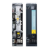
Siemens SINAMICS G130 List Manual (1976 pages)
Brand:
Siemens
| Category:
Control Unit
| Size: 9.61 MB
Table of Contents
Function Diagrams
3
Faults and Alarms
6
SINAMICS G130/G150 List Manual (LH2), 07/2016, A5E03263479A
7
Table of Contents
9
1 Fundamental Safety
11
Parameters
12
Industrial Security
13
2 Parameters
15
Overview of Parameters
16
Safety Instructions
29
Number Ranges of Parameters
31
List of Parameters
34
Parameters for Data Sets
1069
Parameters for Drive Data Sets (DDS)
1071
Parameters for Encoder Data Sets (EDS)
1079
Parameters for Motor Data Sets (MDS)
1081
Parameters for Power Unit Data Sets (PDS)
1084
Parameters for Write Protection and Know-How Protection
1086
Parameters with "KHP_WRITE_NO_LOCK
1088
Parameters with "KHP_ACTIVE_READ
1089
Function Diagrams
1091
Table of Contents
1093
Explanation of the Function Diagrams
1101
CU320-2 Input/Output Terminals
1106
Control Unit Communication
1114
Proifienergy
1119
Profidrive
1122
Internal Control/Status Words
1167
Control Word, Speed Controller
1171
Status Word, Speed Controller
1172
Status Word Closed-Loop Control
1173
Status Word Closed-Loop Current Control
1174
Status Word, Monitoring Functions 1
1175
Status Word, Monitoring Functions 2
1176
Status Word, Monitoring Functions 3
1177
Control Word, Faults/Alarms
1178
Status Word, Faults/Alarms 1 and 2
1179
Sequence Control
1180
Sequencer
1180
Missing Enables, Line Contactor Control, Logic Operation
1180
Brake Control
1183
Basic Brake Control (R0108.14 = 0)
1183
Extended Brake Control, Zero-Speed Detection (R0108.14 = 1)
1183
Extended Brake Control, Open/Close Brake (R0108.14 = 1)
1183
Extended Brake Control, Signal Outputs (R0108.14 = 1)
1183
Safety Integrated Basic Functions
1188
Parameter Manager
1188
Monitoring Functions and Faults/Alarms
1188
SI Status CU, MM, CU + MM, Group STO
1188
S_STW1/2 Safety Control Word 1/2, S_ZSW1/2 Safety Status Word 1/2
1188
STO (Safe Torque Off), SS1 (Safe Stop 1)
1188
STO (Safe Torque Off), Safe Pulse Suppression
1188
SBC (Safe Brake Control), SBA (Safe Brake Adapter)
1188
Safety Integrated Extended Functions
1196
Parameter Manager
1196
SS1, SS2, SOS, Internal STOP B, C, D, F
1196
SBT (Safe Brake Test)
1196
Selection of Active Control Word
1196
SLS: Safely-Limited Speed
1198
SLP (Safely-Limited Position)
1201
SSM (Safe Speed Monitor)
1202
SDI: Safe Direction
1203
SAM: Safe Acceleration Monitor SBR: Safe Brake Ramp
1204
SI Motion Drive-Integrated Control Signals / Status Signals
1207
Safety Integrated TM54F
1210
Overview
1210
Parameter Manager
1210
Configuration, F-DI/F-DO Test
1210
Fail-Safe Digital Inputs (F-DI 0
1210
Fail-Safe Digital Inputs (F-DI 5
1210
Fail-Safe Digital Outputs (F-DO 0
1210
Basic Functions Control Interface (P9601.2/3 = 0 & P9601.6 = 1)
1210
Basic Functions Safe State Selection
1210
Basic Functions Assignment (F-DO 0
1210
Safety Integrated Profisafe
1223
Standard Telegrams
1223
Manufacturer-Specific Telegrams
1223
Setpoint Channel
1226
Overview
1226
Fixed Speed Setpoints
1226
Motorized Potentiometer
1226
Main/Supplementary Setpoint, Setpoint Scaling, Jogging
1226
Direction Limitation and Direction Reversal
1226
Skip Frequency Bands and Speed Limitations
1226
Basic Ramp-Function Generator
1226
Extended Ramp-Function Generator
1226
Ramp-Function Generator Selection, Status Word, Tracking
1226
Encoder Evaluation
1236
Vector Control
1240
Technology Functions
1271
7010 - Friction Characteristic
1271
External Armature Short-Circuit (EASC, P0300 = 2Xx or 4Xx)
1271
Internal Armature Short-Circuit (IASC, P0300 = 2Xx or 4Xx)
1271
DC Braking (P0300 = 1Xx)
1271
7020 - Synchronization
1271
Essential Service Mode (ESM)
1271
Technology Controller
1278
Fixed Values, Binary Selection (R0108.16 = 1 and P2216 = 2)
1278
Fixed Values, Direct Selection (R0108.16 = 1 and P2216 = 1)
1278
Motorized Potentiometer (R0108.16 = 1)
1278
Closed-Loop Control (R0108.16 = 1)
1278
DC-Link Voltage Controller (R0108.16 = 1)
1278
Signals and Monitoring Functions
1284
Overview
1284
Speed Signals 1
1284
Speed Signals
1284
Torque Signals, Motor Blocked/Stalled
1284
Load Monitoring (R0108.17 = 1)
1284
Thermal Monitoring, Motor, Motor Temperature Status Word Faults/Alarms
1284
Motor Temperature Model 1 (I2T)
1284
Motor Temperature Model
1284
Thermal Monitoring, Power Unit
1284
Diagnostics
1296
Overview
1296
Fault Buffer
1296
Alarm Buffer
1296
Faults/Alarms Trigger Word (R2129)
1296
Faults/Alarms Configuration
1296
Measuring Sockets (T0, T1, T2)
1296
Recorder Overview (R0108.5 = 1)
1296
Recorder Sequence Control (R0108.5 = 1)
1296
Function Diagrams
1296
Data Sets
1305
Command Data Sets (CDS)
1305
Drive Data Sets (DDS)
1305
Encoder Data Sets (EDS)
1305
Motor Data Sets (MDS)
1305
Power Unit Data Sets (PDS)
1305
Basic Infeed
1311
8710 - Overview
1311
8720 - Control Word, Sequence Control Infeed
1311
8726 - Status Word, Sequence Control Infeed
1311
8732 - Sequencer
1311
8738 - Missing Enables, Line Contactor Control
1311
Interface to the Basic Infeed Power Unit (Control Signals, Actual Values)
1311
Signals and Monitoring Functions (P3400.0 = 0)
1311
Terminal Board 30 (TB30)
1319
Overview
1319
Digital Inputs, Electrically Isolated (DI 0
1319
Digital Outputs, Electrically Isolated (DO 0
1319
Analog Inputs (AI 0
1319
Analog Outputs (AO 0
1319
Communication Board CAN10 (CBC10)
1325
Receive Telegram, Free PDO Mapping (P8744 = 2)
1325
Receive Telegram, Predefined Connection Set (P8744 = 1)
1325
Send Telegram, Free PDO Mapping (P8744 = 2)
1325
Send Telegram, Predefined Connection Set (P8744 = 1)
1325
Control Word, Canopen
1325
Status Word Canopen
1331
Terminal Module 31 (TM31)
1332
Overview
1332
Digital Inputs, Electrically Isolated (DI 0
1332
Digital Inputs, Electrically Isolated (DI 4
1332
Digital Relay Outputs, Electrically Isolated (DO 0
1332
Digital Inputs/Outputs, Bidirectional (DI/DO 8
1332
Digital Inputs/Outputs, Bidirectional (DI/DO 10
1332
Analog Input 0 (AI 0)
1332
Analog Input 1 (AI 1)
1332
Analog Outputs (AO 0
1333
Temperature Evaluation
1342
Terminal Module 120 (TM120)
1343
Temperature Evaluation Channels 0 and 1 (Kty/Ptc/Bimetal)
1343
Temperature Evaluation Channels 2 and 3 (Kty/Ptc/Bimetal)
1343
Terminal Module 150 (TM150)
1346
Temperature Evaluation Structure (Channels 0
1346
Temperature Evaluation 1X2-, 3-, 4-Wire (Channels 0
1346
Temperature Evaluation 2X2-Wire (Channels 0
1346
Voltage Sensing Module (VSM)
1350
Analog Inputs (AI 0
1350
Temperature Evaluation
1350
Basic Operator Panel 20 (BOP20)
1353
Control Word Interconnection
1353
Siemens SINAMICS G130 Engineering Manual (530 pages)
SINAMICS - Low Voltage SINAMICS Drives
Brand:
Siemens
| Category:
DC Drives
| Size: 12.98 MB
Table of Contents
Mechanical Principles
2
Table of Contents
6
1 Fundamental Principles and System Description
16
Operating Principle of SINAMICS Converters
16
General Operating Principle
16
Pulse Modulation Method
16
Generation of a Variable Voltage by Pulse-Width Modulation
17
Maximum Attainable Output Voltage with Space Vector Modulation SVM
18
Maximum Attainable Output Voltage with Pulse-Edge Modulation PEM
19
The Pulse Frequency and Its Influence on Key System Properties
21
Factory Settings and Ranges of Pulse Frequency Settings
21
Interrelationships between Current Controller Clock Cycle, Pulse Frequency and Output Frequency
22
Influence of the Pulse Frequency on the Inverter Output Current
24
Influence of the Pulse Frequency on Losses and Efficiency of Inverter and Motor
24
Influence of the Pulse Frequency on the Motor Noise
24
Correlation between Pulse Frequency and Motor-Side Options
26
Open-Loop and Closed-Loop Control Modes
27
General Information about Speed Adjustment
27
V/F Control Modes
27
Field-Oriented Control Modes
29
Motion Control
30
A Comparison of the Key Features of Open-Loop and Closed-Loop Control Modes
31
Load Balance on Mechanically Coupled Drives
31
Power Ratings of SINAMICS Converters and Inverters / Definition of the Output Power
33
Supply Systems and Supply System Types
35
General
35
Connection of Converters to the Supply System and Protection of Converters
37
Short Circuit Current Rating (SCCR According to UL)
38
Maximum Short-Circuit Currents (SCCR According to IEC) and Minimum Short-Circuit Currents
39
Connection of Converters to Grounded Systems (TN or TT)
44
Connection of Converters to Non-Grounded Systems (IT)
45
Connection of Converters to Supply Systems with Different Short-Circuit Powers
49
Supply Voltage Variations and Supply Voltage Dips
51
Behaviour of SINAMICS Converters During Supply Voltage Variations and Dips
52
Permissible Harmonics on the Supply Voltage
59
Summary of Permissible Supply System Conditions for SINAMICS Converters
60
Line-Side Contactors and Circuit Breakers
61
Transformers
66
Unit Transformers
66
General Information about Calculating the Required Apparent Power of a Unit Transformer
66
Method of Calculating the Required Apparent Power S of a Unit Transformer
68
Transformer Types
69
Features of Standard Transformers and Converter Transformers
70
Three-Winding Transformers
71
Harmonic Effects on the Supply System
72
General
72
Harmonic Currents of 6-Pulse Rectifier Circuits
74
SINAMICS G130, G150, S120 Basic Infeed and S120 Smart Infeed in Motor Operation
74
SINAMICS S120 Smart Infeed in Regenerative Operation
76
Harmonic Currents of 6-Pulse Rectifier Circuits with Line Harmonics Filter
77
SINAMICS Engineering Manual – November
78
Harmonic Currents of 12-Pulse Rectifier Circuits
79
Harmonic Currents and Harmonic Voltages of Active Infeeds (AFE Technology)
80
Standards and Permissible Harmonics
82
Line-Side Reactors and Filters
86
Line Reactors (Line Commutating Reactors)
86
Line Harmonics Filters (LHF and LHF Compact)
87
Operating Principle of Line Harmonics Filters (LHF and LHF Compact)
87
Line Harmonics Filter (LHF) with Separate Housing (6SL3000-0J
88
Line Harmonics Filter Compact (LHF Compact) as Option L01 for SINAMICS G150
90
Line Filters (Radio Frequency Interference (RFI) Suppression Filter or EMC Filter)
92
General Information and Standards
92
Line Filters for the "First" Environment (Residential) and "Second" Environment (Industrial)
95
Operating Principle of Line Filters
95
Magnitude of Leakage or Interference Currents
96
EMC-Compliant Installation
97
SINAMICS Infeeds and Their Properties
100
Basic Infeed
100
Smart Infeed
102
Active Infeed
105
Comparison of the Properties of the Different SINAMICS Infeeds
110
Redundant Line Supply Concepts
112
Permissible Total Cable Length for S120 Infeed Modules Feeding Multi-Motor Drives
117
SINAMICS Braking Units (Braking Modules and Braking Resistors)
118
SINAMICS Inverters or Motor Modules
119
Operating Principle and Properties
119
Drive Configurations with Multiple Motor Modules Connected to a Common DC Busbar
120
Connection of Motor Modules to the DC Busbar, Fuse Protection and Precharging
120
Arrangement of Motor Modules Along the DC Busbar
122
Permissible Dimensions and Topologies of the DC Busbar
125
Short-Circuit Currents on the DC Busbar
127
Maximum Power Rating of Drive Configurations at a Common DC Busbar
129
Effects of Using Fast-Switching Power Components (Igbts)
131
Increased Current Load on the Inverter Output as a Result of Long Motor Cables
131
Special Issues Relating to Motor-Side Contactors and Circuit Breakers
133
Increased Voltage Stress on the Motor Winding as a Result of Long Motor Cables
134
Bearing Currents Caused by Steep Voltage Edges on the Motor
139
Measures for Reducing Bearing Currents
140
EMC-Compliant Installation for Optimized Equipotential Bonding in the Drive System
141
Insulated Bearing at the Non-Drive End (NDE) of the Motor
145
Other Measures
145
Summary of Bearing Current Types and Counter-Measures
146
Motor-Side Reactors and Filters
148
Motor Reactors
148
Reduction of the Voltage Rate-Of-Rise DV/Dt at the Motor Terminals
148
Reduction of Additional Current Peaks When Long Motor Cables Are Used
148
Permissible Motor Cable Lengths with Motor Reactor(S) for Single- and Multi-Motor Drives
149
Supplementary Conditions Which Apply When Motor Reactors Are Used
152
DV/Dt Filters Plus VPL and DV/Dt Filters Compact Plus VPL
153
Design and Operating Principle
153
Supplementary Conditions Which Apply When DV/Dt-Filters Are Used
154
Sine-Wave Filters
155
Design and Operating Principle
155
Supplementary Conditions Which Apply When Sine-Wave Filters Are Used
156
Comparison of the Properties of the Motor-Side Reactors and Filters
157
Power Cycling Capability of IGBT Modules and Inverter Power Units
159
General
159
IGBT Module with Cyclically Alternating Current Load
159
Dimensioning of the Power Units for Operation at Low Output Frequencies
160
Load Duty Cycles
164
General
164
Standard Load Duty Cycles
164
Free Load Duty Cycles
165
Thermal Monitoring of the Power Unit
179
Operation of Converters at Increased Pulse Frequency
179
Efficiency of SINAMICS Converters at Full Load and at Partial Load
183
Converter Efficiency at Full Load
183
Converter Efficiency at Partial Load
184
Partial Load Efficiency of S120 Basic Line Modules
184
Partial Load Efficiency of S120 Smart Line Modules
185
Partial Load Efficiency of S120 Active Line Modules + Active Interface Modules
185
Partial Load Efficiency of S120 Motor Modules
186
Partial Load Efficiency of G130 / G150 Converters
187
Partial Load Efficiency of S150 Converters
190
Parallel Connections of Converters
193
General
193
Parallel Connections of SINAMICS Converters
193
Parallel Connection of S120 Basic Line Modules
195
Parallel Connection of S120 Smart Line Modules
197
Parallel Connection of S120 Active Line Modules
199
Parallel Connection of S120 Motor Modules
201
Admissible and Inadmissible Winding Systems for Parallel Connections of Converters
203
Liquid-Cooled SINAMICS S120 Units
206
General
206
Design of the Liquid-Cooled SINAMICS S120 Units
206
Cooling Circuit and Coolant Requirements
207
Example of a Closed Cooling Circuit for Liquid-Cooled SINAMICS S120 Units
210
Example of an Open Cooling Circuit for Liquid-Cooled SINAMICS S120 Units
210
Example of Coolant Temperature Control for Condensation Prevention
211
Information about Cooling Circuit Configuration
214
Information about Cabinet Design
223
SINAMICS Engineering Manual – November
224
Advertisement
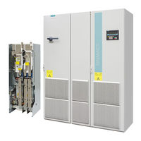
SIEMENS SINAMICS G130 Operating Instructions Manual (610 pages)
Converter built-in units 75 kW-800 kW
Brand:
SIEMENS
| Category:
Inverter
| Size: 14.95 MB
Table of Contents
Preface
5
Table of Contents
9
1 Safety Information
17
Safety Instructions for Electromagnetic Fields (EMF)
21
Handling Electrostatic Sensitive Devices (ESD)
22
Industrial Security
23
Residual Risks of Power Drive Systems
24
2 Device Overview
25
Overview of the Chassis Units
26
Overview of the Power Modules
27
Applications, Features
28
Wiring Principle
30
Type Plate
31
3 Mechanical Installation
33
Assembly
35
Unpacking
36
Power Module
37
Dimension Drawings
38
Control Unit CU320-2
42
TM31 Terminal Module
43
SMC30 Sensor Module
45
4 Electrical Installation
47
Important Safety Precautions
48
Introduction to EMC
49
EMC-Compliant Design
51
Connection Overview
54
Power Connections
58
Connection Cross-Sections, Cable Lengths
59
Connecting the Motor and Power Cables
60
DCPS, DCNS Connection for a DV/Dt Filter with Voltage Peak Limiter
62
Removing the Connection Clip to the Basic Interference Suppression Module for Operation on an Ungrounded Line Supply (IT System)
64
External 24 V DC Supply
69
DRIVE-Cliq Wiring Diagram
70
Signal Connections
71
Control Unit CU320-2 DP
75
Control Unit CU320-2 PN
90
TM31 Terminal Module
103
Sensor Module Cabinet-Mounted SMC30
113
Connection
117
Connection Examples
122
TM54F Terminal Module
123
Chapter Content
125
STARTER Commissioning Tool
126
Installing STARTER
128
Procedure for Commissioning Via STARTER
129
Configuring the Drive Unit
137
Transferring the Drive Project
162
Commissioning with STARTER Via Ethernet
164
The AOP30 Operator Panel
170
First Commissioning with the AOP30
171
Basic Commissioning
173
Status after Commissioning
182
Commissioning an Encoder with Gear Factor
183
Chapter Content
185
General Information about Command and Setpoint Sources
186
Basic Information about the Drive System
187
Drive Objects
190
Data Sets
192
BICO Technology: Interconnecting Signals
197
Propagation of Faults
203
Command Sources
204
TM31 Terminals" Default Setting
206
CU Terminals" Default Setting
208
Profidrive+Tm31" Default Setting
210
Setpoint Sources
212
Motorized Potentiometer
214
Fixed Speed Setpoints
215
Communication According to Profidrive
217
Application Classes
219
Cyclic Communication
220
Zsw1
221
Telegrams and Process Data
221
Structure of the Telegrams
223
Overview of Control Words and Setpoints
224
Acyclic Communication
225
Structure of Requests and Responses
227
Determining the Drive Object Numbers
233
Example 2: Writing Parameters (Multi-Parameter Request)
235
Diagnostics Channels
238
Diagnostics Via PROFINET
239
Diagnostics Via PROFIBUS
242
Further Information about Profidrive Communication
246
Communication Via PROFIBUS DP
247
Monitoring: Telegram Failure
248
Further Information about Communication Via PROFIBUS DP
249
Communication Via PROFINET IO
250
Activating Online Operation: STARTER Via PROFINET IO
252
General Information about PROFINET IO
256
Real-Time (RT) and Isochronous Real-Time (IRT) Communication
257
Addresses
258
Data Transmission
260
Communication Channels
261
Profienergy
262
Tasks of Profienergy
264
Profienergy - Properties of the Drive System
265
Profienergy Measured Values
266
Transition into the Energy-Saving Mode from the Profidrive Operating State (S4)
267
Profienergy Applications
268
Further Information about Communication Via PROFINET IO
271
Topology
273
Configuring and Commissioning
275
Actual Speed Value Part 1
276
Actual Torque Value Part 1
276
Actual Fault Code
276
R2131
276
Telegram Word
276
Slots in the Send Buffer P8871[X]
277
Telegram Word
277
R0046
278
Example
280
Communication Failure When Booting or in Cyclic Operation
282
Transmission Times for SINAMICS Link
283
Communication Via Ethernet/Ip
284
Configuring Communication
286
Integrate the Drive Device into the Ethernet Network Via DHCP
296
Parameters, Faults and Alarms
297
Communication Via MODBUS TCP
298
Configuring Modbus TCP Via Interface X150
299
Configuring Modbus TCP Via Interface X1400
300
Mapping Tables
301
Write and Read Access Using Function Codes
304
Communication Via Data Set 47
306
Communication Details
307
Examples: Read Parameter
308
Examples: Write Parameter
309
Communication Procedure
310
Parameters, Faults and Alarms
311
Communication Services and Used Port Numbers
312
Parallel Operation of Communication Interfaces
314
Engineering Software Drive Control Chart (DCC)
318
Chapter Content
319
Siemens SINAMICS G130 Engineering Manual (396 pages)
Brand:
Siemens
| Category:
DC Drives
| Size: 7.06 MB
Table of Contents
Siemens AG
4
Table of Contents
5
Fundamental Principles and System Description
12
Operating Principle of SINAMICS Converters
12
General Operating Principle
12
Pulse Modulation Method
12
Generation of a Variable Voltage by Pulse Width Modulation
13
Maximum Attainable Output Voltage with Space Vector Modulation SVM
15
Maximum Attainable Output Voltage with Pulse-Edge Modulation PEM
15
The Pulse Frequency and Its Influence on Key System Properties
17
Output Power Ratings of SINAMICS Converters and Inverters / Definition of the Output Power
19
Supply Systems and Supply System Types
21
General
21
Connection of Converters to Grounded Systems (TN or TT)
22
Connection of Converters to Non-Grounded Systems (IT)
22
Connection of Converters to Supply Systems with Different Short-Circuit Powers
23
Supply Voltage Variations and Supply Voltage Dips
25
Behaviour of SINAMICS Converters During Supply Voltage Variations and Dips
26
Permissible Harmonics on the Supply Voltage
32
Transformers
33
Unit Transformers
33
Transformer Types
34
Features of Standard Transformers and Converter Transformers
35
Three-Winding Transformers
36
Harmonic Effects on the Supply System
37
General
37
Harmonic Currents of 6-Pulse Rectifier Circuits
39
Harmonic Currents of 6-Pulse Rectifier Circuits with Line Harmonics Filter
42
Harmonic Currents of 12-Pulse Rectifier Circuits
44
Harmonic Currents and Harmonic Voltages of Active Infeeds (AFE Technology)
45
Standards and Permissible Harmonics
47
Line Reactors (Line Commutating Reactors)
51
Line Harmonics Filter (LHF)
52
Line Filters (Radio Frequency Interference (RFI) Suppression Filters or EMC Filters)
54
General Information and Standards
54
Line Filters for the "First" Environment (Residential) and "Second" Environment (Industrial)
56
Operating Principle of Line Filters
57
Magnitude of Leakage or Interference Currents
57
EMC-Compliant Installation
58
SINAMICS Infeeds and Their Properties
60
Basic Infeed
60
Smart Infeed
62
Active Infeed
64
Comparison of the Properties of the Different SINAMICS Infeeds
67
Redundant Line Supply Concepts
68
Permissible Total Cable Length for S120 Infeed Modules Feeding Multi-Motor Drives
74
Effects of Using Fast-Switching Power Components (Igbts)
75
Increased Current Load on the Inverter Output as a Result of Long Motor Cables
75
Increased Voltage Stress on the Motor Winding as a Result of Long Motor Cables
77
Bearing Currents Caused by Steep Voltage Edges on the Motor
81
Measures for Reducing Bearing Currents
82
EMC-Compliant Installation for Optimized Equipotential Bonding in the Drive System
83
Insulated Bearing at the Non-Drive End (NDE End) of the Motor
86
Other Measures
86
Siemens SINAMICS G130 Manual (312 pages)
Safety Integrated
Brand:
Siemens
| Category:
Control Unit
| Size: 5.21 MB
Table of Contents
Preface
5
Table of Contents
11
1 Typicals and Regulations
17
General Information
17
Aims
17
Functional Safety
17
Safety of Machinery in Europe
18
Machinery Directive
18
Harmonized European Standards
19
Standards for Implementing Safety-Related Controllers
21
ISO 13849-1 (Previously en 954-1)
23
Series of Standards en 61508 (VDE 0803)
26
Risk Analysis/Assessment
27
Risk Reduction
29
Residual Risk
29
Machine Safety in the USA
30
Minimum Requirements of the OSHA
30
NRTL Listing
31
Nfpa 79
31
Ansi B11
32
Machine Safety in Japan
32
Equipment Regulations
32
Other Safety-Related Issues
33
Information Sheets Issued by the Employer's Liability Insurance Association
33
Additional References
33
2 General Information about SINAMICS Safety Integrated
35
Safety Integrated Functions
35
Preconditions for Safety Integrated Basic Functions
36
Preconditions for Safety Integrated Extended Functions
37
Controlling the Safety Integrated Functions
37
Parameter, Checksum, Version, Password
39
DRIVE-Cliq Rules for Safety Integrated Functions
42
3 System Features
43
Latest Information
43
Certification
44
Safety Instructions
45
Probability of Failure of the Safety Functions (PFH Value)
47
Response Times
48
Response Times Safety Integrated Basic Functions
48
Response Times, Safety Integrated Extended Functions with Encoder
49
Response Times for Safety Integrated Extended Functions Without Encoder
50
Residual Risk
51
4 Supported Functions
53
Content of this Chapter
53
Sinamics G130
54
Basic Functions
54
Extended Functions
54
Sinamics G150
55
Basic Functions
55
Extended Functions
55
SINAMICS S120 Chassis
56
Basic Functions
56
Extended Functions
57
SINAMICS S120 Cabinet Modules
58
Booksize Format Motor Module
58
Basic Functions
58
Extended Functions
59
Motor Module in Chassis Format
60
Basic Functions
60
Extended Functions
61
Sinamics S150
62
Basic Functions
62
Extended Functions
63
Siemens SINAMICS G130 Function Manual (108 pages)
Chassis, Cabinet Modules
Brand:
Siemens
| Category:
Industrial Equipment
| Size: 1.93 MB
Table of Contents
Preface
5
Table of Contents
7
Safety Information
9
Industrial Security
10
Introduction
13
General Information about SINAMICS Safety Integrated
15
Supported Functions
15
Sinamics G130
19
Basic Functions
19
Extended Functions
20
Sinamics G150
21
Basic Functions
21
Extended Functions
22
SINAMICS S120 Chassis and Chassis-2
23
Basic Functions
23
Extended Functions
23
Advanced Functions
25
SINAMICS S120 Cabinet Modules, Booksize Format
26
Basic Functions
26
Extended Functions
27
SINAMICS S120 Cabinet Modules, Chassis and Chassis-2 Formats
28
Basic Functions
28
Extended Functions
29
Sinamics S150
30
Basic Functions
30
Extended Functions
31
Drive Monitoring with or Without Encoder
32
Description of Safety Integrated Functions
33
Preconditions for Safety Integrated Basic Functions
33
Preconditions for Safety Integrated Extended Functions
34
Preconditions for Safety Integrated Advanced Functions
35
Controlling the Safety Functions
37
Control Possibilities
37
Control of "STO" and "SS1" Via Terminal Module for Option K82
38
Terminal Module for Control of "STO" and "SS1" for SINAMICS G150
38
Terminal Module for Control of "STO" and "SS1" for SINAMICS S120 Cabinet Modules
44
General Information
44
Use of the K82 Option with Control Unit CU320-2
47
Use of the K82 Option with Control Unit CU320-2
48
Wiring
48
Terminal Module for Control of "STO" and "SS1" for SINAMICS S150
49
Technical Data
53
Control of "STO" and "SS1" Via Terminals on the Control Unit and the Motor/Power Module
54
Simultaneity and Tolerance Time of the Two Monitoring Channels
57
Bit Pattern Test
59
Control of "STO" and "SS1" for SINAMICS G130
60
Control of "STO" and "SS1" for SINAMICS G150
66
Control of "STO" and "SS1" for SINAMICS S120 Chassis and Chassis-2
72
Control of "STO" and "SS1" for SINAMICS S120 Cabinet Modules
78
Control of "STO" and "SS1" for SINAMICS S150
84
Siemens SINAMICS G130 Function Manual (102 pages)
Brand:
Siemens
| Category:
DC Drives
| Size: 1.14 MB
Table of Contents
Preface
5
Table of Contents
7
1 Safety Information
9
Industrial Security
10
2 Introduction
13
3 General Information about SINAMICS Safety Integrated
15
Supported Functions
15
Sinamics G130
18
Basic Functions
18
Extended Functions
18
Sinamics G150
20
Basic Functions
20
Extended Functions
20
SINAMICS S120 Chassis
22
Basic Functions
22
Extended Functions
22
SINAMICS S120 Cabinet Modules, Booksize Format
24
Basic Functions
24
Extended Functions
24
SINAMICS S120 Cabinet Modules, Chassis Format
26
Basic Functions
26
Extended Functions
26
Sinamics S150
28
Basic Functions
28
Extended Functions
28
Drive Monitoring with or Without Encoder
29
4 Description of Safety Integrated Functions
31
Preconditions for Safety Integrated Basic Functions
31
Preconditions for Safety Integrated Extended Functions
32
5 Controlling the Safety Functions
33
Control Possibilities
33
Control of "STO" and "SS1" Via Terminal Module for Option K82
34
Terminal Module for Control of "STO" and "SS1" for SINAMICS G150
34
Terminal Module for Control of "STO" and "SS1" for SINAMICS S120 Cabinet Modules
39
General Information
39
Use of the K82 Option with Control Unit CU320-2
43
Use of the K82 Option with Control Unit CU320-2
44
Wiring
44
Terminal Module for Control of "STO" and "SS1" for SINAMICS S150
44
Control of "STO" and "SS1" Via Terminals on the Control Unit and the Motor/Power Module
50
Simultaneity and Tolerance Time of the Two Monitoring Channels
53
Bit Pattern Test
55
Control of "STO" and "SS1" for SINAMICS G130
56
Control of "STO" and "SS1" for SINAMICS G150
62
Control of "STO" and "SS1" for SINAMICS S120 Chassis
68
Control of "STO" and "SS1" for SINAMICS S120 Cabinet Modules
74
Control of "STO" and "SS1" for SINAMICS S150
80
Activating "SBC" Via the Safe Brake Adapter
86
Activating "SBC" Via the Safe Brake Adapter for Option K88 (230 V AC)
86
Safe Brake Adapter SBA 230 V AC for SINAMICS G130/SINAMICS S120 Chassis
90
Control by Way of Profisafe
95
Control Via TM54F
96
Control Via TM54F for SINAMICS G130, S120 Chassis
96
Control Via Option K87 for SINAMICS S120 Cabinet Modules
96
Control Via K87 for SINAMICS S150
96
Motion Monitoring Without Selection
97
Siemens SINAMICS G130 Operating Instructions Manual (60 pages)
Operator Panel
Brand:
Siemens
| Category:
Control Panel
| Size: 1.85 MB
Table of Contents
Table of Contents
5
1 Safety Information
7
General Safety Instructions
7
Handling the AOP30 Backup Battery
11
Handling Electrostatic Sensitive Devices (ESD)
12
Industrial Security
13
2 General
15
3 Mechanical Installation
17
4 Connection
21
5 Control Via the Operator Panel
25
Operator Panel (AOP30) Overview and Menu Structure
25
Menu: Operation Screen
27
Menu: Parameterization
28
Menu: Fault/Alarm Memory
29
Menu Commissioning / Service
30
Drive Commissioning
30
Device Commissioning
31
Drive Diagnostics
31
AOP Settings
33
AOP Diagnostics
40
Sprachauswahl/Language Selection
42
Operation Via the Operator Panel (LOCAL Mode)
42
LOCAL/REMOTE Key
43
ON Key / off Key
43
Switching between Clockwise and Counter-Clockwise Rotation
44
Jog
44
Increase Setpoint / Decrease Setpoint
44
AOP Setpoint
45
Lock AOP LOCAL Mode
46
Acknowledge Error from the AOP
46
CDS Setting Via AOP
46
Operator Input Inhibit / Parameterization Inhibit
47
Faults and Alarms
48
Saving the Parameters Permanently
50
Parameterization Errors
50
6 Maintenance and Servicing
51
Replacing the Backup Battery
51
Downloading New Operator Panel Firmware from the PC
53
7 Technical Specifications
55
Index
57
Siemens SINAMICS G130 Operating Instructions Manual (54 pages)
AOP30 Advanced Operator Panel
Brand:
Siemens
| Category:
Media Converter
| Size: 1.04 MB
Table of Contents
Table of Contents
5
1 Safety Information
7
Warnings
7
Safety and Application Instructions
8
Components that Can be Destroyed by Electrostatic Discharge (ESD)
9
2 General
11
3 Mechanical Installation
13
4 Connection
17
5 Control Via the Operator Panel
21
Operator Panel (AOP30) Overview and Menu Structure
21
Menu: Operation Screen
23
Menu: Parameterization
24
Menu: Fault/Alarm Memory
26
Menu Commissioning / Service
27
Drive Commissioning
27
Device Commissioning
27
Drive Diagnostics
28
AOP Settings
29
AOP30 Diagnosis
35
Sprachauswahl/Language Selection
36
Operation Via the Operator Panel (LOCAL Mode)
36
LOCAL/REMOTE Key
37
ON Key / off Key
38
Switching between Clockwise and Counter-Clockwise Rotation
38
Jog
39
Increase Setpoint / Decrease Setpoint
39
AOP Setpoint
40
Timeout Monitoring
41
Operator Input Inhibit / Parameterization Inhibit
42
Faults and Alarms
44
Saving the Parameters Permanently
45
Parameterization Errors
46
6 Maintenance and Servicing
47
Replacing the Backup Battery
47
Downloading New Operator Panel Firmware from the PC
49
7 Technical Specifications
51
Index
53
Siemens SINAMICS G130 Operating Instructions Manual (46 pages)
Braking Module / braking resistor
Brand:
Siemens
| Category:
DC Drives
| Size: 1.27 MB
Table of Contents
Table of Contents
5
1 Safety Information
7
Warnings
7
Safety and Application Instructions
8
Components that Can be Destroyed by Electrostatic Discharge (ESD)
9
2 General
11
Braking Module
11
Braking Resistor
13
3 Mechanical Installation
15
General
15
Braking Modules: Overview
16
Installing the Braking Module
19
Installing the Braking Module in a Power Module, Frame Size FX
19
Installing the Braking Module in a Power Module Frame Size GX
22
Installing the Braking Module in a Power Module Frame Size HX
25
Installing the Braking Module in a Power Module Frame Size JX
26
Installing the Braking Resistor
27
4 Connection
29
Cable Lugs
30
Connecting the Braking Module
31
Connecting the Braking Resistor
34
Disabling the VDC-Max Controller
35
5 Maintenance and Servicing
37
6 Technical Specifications
39
Siemens SINAMICS G130 Operating Instructions Manual (46 pages)
dV/dt filter plus Voltage Peak Limiter
Brand:
Siemens
| Category:
Control Unit
| Size: 0.59 MB
Table of Contents
Table of Contents
5
1 Safety Information
7
Warnings
7
Safety and Application Instructions
8
Components that Can be Destroyed by Electrostatic Discharge (ESD)
9
2 General
11
3 Mechanical Installation
19
4 Electrical Installation
25
5 Maintenance and Servicing
31
6 Technical Specifications
33
Siemens SINAMICS G130 Operating Instructions Manual (46 pages)
dV/dt filter compact plus Voltage Peak Limiter
Brand:
Siemens
| Category:
Inverter
| Size: 1.03 MB
Table of Contents
Table of Contents
5
Safety Information
7
General Safety Instructions
7
Handling Electrostatic Sensitive Devices (ESD)
11
General
13
Mechanical Installation
19
Electrical Installation
27
Maintenance and Servicing
35
Technical Specifications
37
Siemens SINAMICS G130 Operating Instructions Manual (46 pages)
dV/dt filter plus Voltage Peak Limiter
Brand:
Siemens
| Category:
DC Drives
| Size: 0.87 MB
Table of Contents
Table of Contents
5
Safety Information
7
General Safety Instructions
7
Handling Electrostatic Sensitive Devices (ESD)
11
General
13
Mechanical Installation
21
Electrical Installation
27
Maintenance and Servicing
31
Technical Specifications
33
Siemens SINAMICS G130 Operating Instructions Manual (42 pages)
dV/dt filter compact plus Voltage Peak Limiter
Brand:
Siemens
| Category:
Controller
| Size: 0.69 MB
Table of Contents
Table of Contents
5
1 Safety Information
7
Warnings
7
Safety and Application Instructions
8
Components that Can be Destroyed by Electrostatic Discharge (ESD)
9
2 General
11
3 Mechanical Installation
17
4 Electrical Installation
23
5 Maintenance and Servicing
31
6 Technical Specifications
33
Siemens SINAMICS G130 Operating Instructions Manual (34 pages)
Cabinet design and EMC
Brand:
Siemens
| Category:
Control Unit
| Size: 0.66 MB
Table of Contents
Table of Contents
5
1 Safety Information
7
General Safety Instructions
7
Safety Instructions for Electromagnetic Fields (EMF)
11
Handling Electrostatic Sensitive Devices (ESD)
12
Industrial Security
13
Residual Risks of Power Drive Systems
14
2 General
15
Safety Information
15
Directives
16
Standards
17
3 Basic Information about EMC
21
Introduction to EMC
21
4 EMC-Compliant Design and Control Cabinet Configuration
25
5 Cabinet Air Conditioning
27
General
27
Ventilation
28
Siemens SINAMICS G130 Operating Instructions Manual (42 pages)
dv/dt filter compact plus Voltage Peak Limiter
Brand:
Siemens
| Category:
Chassis
| Size: 1.61 MB
Table of Contents
Table of Contents
5
Safety Information
7
General Safety Instructions
7
Handling Electrostatic Sensitive Devices (ESD)
12
General
13
Mechanical Installation
19
Electrical Installation
25
Maintenance and Servicing
31
Technical Specifications
33
Siemens SINAMICS G130 Operating Instructions Manual (28 pages)
Voltage Sensing Module 10 (VSM10)
Brand:
Siemens
| Category:
Control Unit
| Size: 1.07 MB
Table of Contents
Table of Contents
5
1 Safety Information
7
General Safety Instructions
7
Handling Electrostatic Sensitive Devices (ESD)
12
2 General
13
Safety Information
13
3 Mechanical Installation
15
4 Electrical Installation
17
Overview
17
Connection Diagram
19
Interface Description
20
Electronics Power Supply X524
20
DRIVE-Cliq Interface X500
21
X520 Analog Inputs/Temperature Sensor
21
X521 Three-Phase Line Supply Voltage Sensing up to 100 V (Phase-To-Phase)
23
X522 Three-Phase Line Supply Voltage Sensing up to 690 V (Phase-To-Phase)
24
X530 Neutral Point Grounding
24
Operating on an Ungrounded Line Supply (IT System)
25
Significance of the Leds for the Voltage Sensing Module VSM10
26
5 Technical Specifications
27
Siemens SINAMICS G130 Operating Instructions Manual (30 pages)
Terminal Module 150 (TM150)
Brand:
Siemens
| Category:
Control Unit
| Size: 0.9 MB
Table of Contents
Table of Contents
5
1 Safety Information
7
General Safety Instructions
7
Handling Electrostatic Sensitive Devices (ESD)
11
2 General Information
13
Safety Information
14
3 Mechanical Installation
17
4 Electrical Installation
19
Overview
19
Interface Description
20
X524 Electronics Power Supply
20
X500/X501 DRIVE-Cliq Interfaces
20
X531-X536 Temperature Sensor Inputs
21
Meaning of the Leds on the Terminal Module TM150
23
Connection Examples
24
Protective Conductor Connection and Shield Support
26
5 Technical Specifications
27
Siemens SINAMICS G130 Operating Instructions Manual (38 pages)
dV/dt filter plus Voltage Peak Limiter
Brand:
Siemens
| Category:
Controller
| Size: 1.14 MB
Table of Contents
Table of Contents
5
Safety Information
7
General Safety Instructions
7
Handling Electrostatic Sensitive Devices (ESD)
12
General
13
Mechanical Installation
19
Electrical Installation
25
Maintenance and Servicing
29
Technical Specifications
31
Siemens SINAMICS G130 Operating Instructions Manual (30 pages)
Basic Operator Panel 20
Brand:
Siemens
| Category:
Control Panel
| Size: 0.69 MB
Table of Contents
Table of Contents
5
1 Safety Information
7
Warnings
7
Safety and Application Instructions
8
Components that Can be Destroyed by Electrostatic Discharge (ESD)
9
2 General
11
3 Installation
13
Removal
14
4 Setting Parameters with the BOP20
15
BOP20 Overview
15
Displays/Indicators and Using the BOP20
19
Fault and Alarm Displays
23
Controlling the Drive Using the BOP20
24
Important Functions Via BOP20
25
5 Technical Specifications
27
Siemens SINAMICS G130 Operating Instructions Manual (26 pages)
Terminal Module 150 (TM150)
Brand:
Siemens
| Category:
Control Unit
| Size: 0.62 MB
Table of Contents
Table of Contents
5
1 Safety Information
7
Warnings
7
Safety and Application Instructions
8
Components that Can be Destroyed by Electrostatic Discharge (ESD)
9
2 General Information
11
Safety Information
11
3 Mechanical Installation
13
4 Electrical Installation
15
Overview
15
Interface Description
16
X524 Electronics Power Supply
16
X500/X501 DRIVE-Cliq Interfaces
16
X531-X536 Temperature Sensor Inputs
17
Meaning of the Leds on the Terminal Module TM150
18
Connection Examples
19
Protective Conductor Connection and Shield Support
21
5 Technical Specifications
23
Siemens SINAMICS G130 Operating Instructions Manual (30 pages)
Line harmonics filter
Brand:
Siemens
| Category:
Water Filtration Systems
| Size: 0.64 MB
Table of Contents
Table of Contents
5
1 Safety Information
7
Warnings
7
Line Harmonics Filters Operating Instructions, 07/07, A5E01347987A
7
Safety and Operating Instructions
8
2 General
9
3 Mechanical Installation
15
General
15
Dimension Drawings
16
4 Electrical Installation
19
5 Maintenance and Servicing
25
6 Technical Specifications
27
Siemens SINAMICS G130 Operating Instructions Manual (24 pages)
Brand:
Siemens
| Category:
Industrial Electrical
| Size: 0.41 MB
Table of Contents
Table of Contents
5
Safety Information
7
Warnings
7
Safety and Application Instructions
8
Components that Can be Destroyed by Electrostatic Discharge (ESD)
9
General
11
Safety Information
11
Mechanical Installation
13
Electrical Installation
15
Overview
15
Connection Diagram
16
Interface Description
17
Electronics Power Supply X524
17
DRIVE-Cliq Interface X500
18
X520 Analog Inputs/Temperature Sensor
18
X521 Three-Phase Line Supply Voltage Sensing up to 100 V (Phase-To-Phase)
19
X522 Three-Phase Line Supply Voltage Sensing up to 690 V (Phase-To-Phase)
20
Significance of the Leds for the Voltage Sensing Module VSM10
20
Technical Specifications
21
Siemens SINAMICS G130 Operating Instructions Manual (31 pages)
Cabinet design and EMC
Brand:
Siemens
| Category:
Servo Drives
| Size: 0.47 MB
Table of Contents
Safety Information
7
Safety and Operating Instructions
8
Components that Can be Destroyed by Electrostatic Discharge (ESD)
9
General
11
Directives
12
Standards
13
Basic Information about EMC
17
EMC-Compliant Design and Control Cabinet Configuration
21
Cabinet Air Conditioning
23
Ventilation
24
Siemens SINAMICS G130 Operating Instructions Manual (30 pages)
Motor reactors
Brand:
Siemens
| Category:
Chassis
| Size: 0.76 MB
Table of Contents
Table of Contents
5
Safety Information
7
General Safety Instructions
7
General
13
Mechanical Installation
17
Electrical Installation
21
Technical Specifications
23
Siemens SINAMICS G130 Operating Instructions Manual (28 pages)
Line reactors
Brand:
Siemens
| Category:
Media Converter
| Size: 0.5 MB
Table of Contents
Table of Contents
5
Safety Information
7
General Safety Instructions
7
General
11
Mechanical Installation
15
Electrical Installation
19
Technical Specifications
21
Siemens SINAMICS G130 Operating Instructions Manual (28 pages)
Line reactors
Brand:
Siemens
| Category:
Industrial Electrical
| Size: 0.62 MB
Table of Contents
Table of Contents
5
Safety Information
7
General Safety Instructions
7
General
13
Mechanical Installation
17
Electrical Installation
21
Technical Specifications
23
Siemens SINAMICS G130 Operating Instructions Manual (28 pages)
Motor Reactors
Brand:
Siemens
| Category:
Controller
| Size: 0.6 MB
Table of Contents
Table of Contents
5
Safety Information
7
General Safety Instructions
7
General
11
Mechanical Installation
15
Electrical Installation
19
Technical Specifications
21
Siemens SINAMICS G130 Operating Instructions Manual (26 pages)
Line filters
Brand:
Siemens
| Category:
Water Filtration Systems
| Size: 0.53 MB
Table of Contents
Table of Contents
5
Safety Information
7
General Safety Instructions
7
Handling Electrostatic Sensitive Devices (ESD)
11
General
13
Mechanical Installation
17
Electrical Installation
19
Technical Specifications
21
Siemens SINAMICS G130 Operating Instructions Manual (26 pages)
Motor reactors
Brand:
Siemens
| Category:
Media Converter
| Size: 0.33 MB
Table of Contents
Table of Contents
5
Safety Information
7
Warnings
7
Safety and Application Instructions
8
General
9
Mechanical Installation
13
Electrical Installation
17
Technical Specifications
19
Siemens SINAMICS G130 Operating Instructions Manual (24 pages)
Brand:
Siemens
| Category:
Terminal Block
| Size: 0.61 MB
Table of Contents
Table of Contents
5
1 Safety Information
7
Warnings
7
Safety and Application Instructions
8
Components that Can be Destroyed by Electrostatic Discharge (ESD)
9
2 General
11
3 Mechanical Installation
13
4 Electrical Installation
15
5 Technical Specifications
21
Siemens SINAMICS G130 Operating Instructions Manual (24 pages)
Line reactors
Brand:
Siemens
| Category:
Control Unit
| Size: 0.37 MB
Table of Contents
Table of Contents
5
Safety Information
7
Warnings
7
Safety and Application Instructions
8
General
9
Mechanical Installation
11
Electrical Installation
15
Technical Specifications
17
Siemens SINAMICS G130 Operating Instructions Manual (24 pages)
Sine-wave filter
Brand:
Siemens
| Category:
DC Drives
| Size: 0.47 MB
Table of Contents
Table of Contents
5
Safety Information
7
General Safety Instructions
7
Handling Electrostatic Sensitive Devices (ESD)
11
General
13
Mechanical Installation
17
Electrical Installation
19
Technical Specifications
21
Siemens SINAMICS G130 Operating Instructions Manual (24 pages)
Sine-wave filter
Brand:
Siemens
| Category:
Water Filtration Systems
| Size: 0.65 MB
Table of Contents
Table of Contents
5
Safety Information
7
General Safety Instructions
7
Handling Electrostatic Sensitive Devices (ESD)
12
General
13
Mechanical Installation
17
Electrical Installation
19
Technical Specifications
21
Siemens SINAMICS G130 Operating Instructions Manual (22 pages)
Sine-wave filter
Brand:
Siemens
| Category:
Water Filtration Systems
| Size: 0.28 MB
Table of Contents
Table of Contents
5
1 Safety Information
7
Warnings
7
Safety and Operating Instructions
8
Components that Can be Destroyed by Electrostatic Discharge (ESD)
9
2 General
11
3 Mechanical Installation
15
4 Electrical Installation
17
5 Technical Specifications
19
Siemens SINAMICS G130 Operating Instructions Manual (22 pages)
Line filter
Brand:
Siemens
| Category:
Water Filtration Systems
| Size: 0.32 MB
Table of Contents
Table of Contents
5
1 Safety Information
7
Warnings
7
Safety and Application Instructions
8
Components that Can be Destroyed by Electrostatic Discharge (ESD)
9
2 General
11
3 Mechanical Installation
15
4 Electrical Installation
17
5 Technical Specifications
19
Advertisement
Related Products
Siemens SINAMICS G150
Siemens SINAMICS G120C DP
Siemens SINAMICS G120X
Siemens SINAMICS G110D 6SL3511-0PE17-5AM0
Siemens SINAMICS G110D 6SL3511-0PE21-5AM0
Siemens SINAMICS G110D 6SL3511-0PE25-5AM0
Siemens SINAMICS G110D 6SL3511-0PE27-5AM0
Siemens SINAMICS G110D 6SL3511-0PE23-0AM0
Siemens SINAMICS G110D 6SL3511-0PE24-0AM0
Siemens SINAMICS G120 PM240P-2
Siemens Categories
Industrial Equipment
Controller
Oven
Control Unit
Washer
More Siemens Manuals
Login
Sign In
OR
Sign in with Facebook
Sign in with Google
Upload manual
Upload from disk
Upload from URL