Siemens SINAMICS G130 Operating Instructions Manual
Converter built-in units 75 kw-800 kw
Hide thumbs
Also See for SINAMICS G130:
- List manual (1976 pages) ,
- Engineering manual (530 pages) ,
- Manual (312 pages)
Table of Contents
Advertisement
Quick Links
Advertisement
Table of Contents

Related Manuals for Siemens SINAMICS G130


Summary of Contents for Siemens SINAMICS G130
- Page 3 ___________________ Inverter chassis units Preface ___________________ Safety information ___________________ SINAMICS Device overview ___________________ Mechanical installation SINAMICS G130 Inverter chassis units ___________________ Electrical installation ___________________ Commissioning Operating Instructions ___________________ Operation ___________________ Setpoint channel and closed- loop control ___________________ Output terminals ___________________...
- Page 4 Note the following: WARNING Siemens products may only be used for the applications described in the catalog and in the relevant technical documentation. If products and components from other manufacturers are used, these must be recommended or approved by Siemens. Proper transport, storage, installation, assembly, commissioning, operation and maintenance are required to ensure that the products operate safely and without any problems.
-
Page 5: Preface
Preface Structure of this documentation The customer documentation comprises the following documents: ● Converter Operating Instructions The Operating Instructions consist of the following sections: – Device description – Mechanical installation – Electrical installation – Commissioning guide – Description of function –... - Page 6 – Programming and Operating Manual: DCC Editor description – Function Manual: Description of the standard DCC blocks Documentation in the Internet The documentation on SINAMICS G130 can be found on the Internet under the following link (https://support.industry.siemens.com/cs/ww/en/ps/13226/man). Technical support If you have any questions, please contact our hotline:...
- Page 7 In addition, measures for proper plant design to meet EMC requirements are described in detail in this manual and the "SINAMICS Low Voltage Configuration Manual". Certifications The following certifications can be found on the Internet under the link SINAMICS G130 certificates (https://support.industry.siemens.com/cs/de/en/ps/13226/cert): ● EC declaration of conformity with reference to the EMC directive: ●...
- Page 8 Preface Inverter chassis units Operating Instructions, 07/2016, A5E00331449A...
-
Page 9: Table Of Contents
Table of contents Preface ..............................5 Safety information ..........................17 General safety instructions ..................... 17 Safety instructions for electromagnetic fields (EMF) .............. 21 Handling electrostatic sensitive devices (ESD) ..............22 Industrial security ........................23 Residual risks of power drive systems ..................24 Device overview ............................ - Page 10 Table of contents EMC-compliant design ......................51 Connection overview ......................54 Power connections ......................... 58 4.7.1 Cable lugs ..........................58 4.7.2 Connection cross-sections, cable lengths ................59 4.7.3 Connecting the motor and power cables ................60 4.7.4 DCPS, DCNS connection for a dV/dt filter with Voltage Peak Limiter ........62 4.7.5 Adjusting the fan voltage ......................
- Page 11 Table of contents 6.3.1 Parameters ........................... 187 6.3.2 Drive objects ......................... 190 6.3.3 Data sets ..........................192 6.3.4 BICO technology: interconnecting signals ................197 6.3.5 Propagation of faults ......................203 Command sources ........................ 204 6.4.1 "PROFIdrive" default setting ....................204 6.4.2 "TM31 terminals"...
- Page 12 Table of contents 6.8.4.5 PROFIenergy measured values ................... 266 6.8.4.6 PROFIenergy energy-saving mode ..................266 6.8.4.7 Transition into the energy-saving mode from the PROFIdrive operating state (S4) .... 267 6.8.4.8 Inhibit PROFIenergy and idle time ..................267 6.8.4.9 PROFIenergy applications ....................268 6.8.4.10 Function diagrams and parameters ..................
- Page 13 Table of contents 7.3.1 Voltage boost ........................331 7.3.2 Resonance damping ......................334 7.3.3 Slip compensation ......................... 335 Vector speed/torque control with/without encoder ..............337 7.4.1 Vector control without encoder ..................... 338 7.4.2 Vector control with encoder ....................345 7.4.3 Actual speed value filter ......................
- Page 14 Table of contents 9.2.9.3 Internal armature short-circuit braking ................. 407 9.2.9.4 DC braking ........................... 408 9.2.10 Increasing the output frequency ................... 410 9.2.10.1 Description ........................... 410 9.2.10.2 Default pulse frequencies ....................411 9.2.10.3 Increasing the pulse frequency .................... 411 9.2.10.4 Maximum output frequency achieved by increasing the pulse frequency ......
- Page 15 Table of contents 9.4.5.1 Description ..........................481 9.4.5.2 Temperature sensor connection at the customer terminal block TM31 ....... 481 9.4.5.3 Temperature sensor connection at a Sensor Module ............482 9.4.5.4 Temperature sensor connection directly at the Control Interface Module ......483 9.4.5.5 Temperature sensor evaluation ....................
- Page 16 Table of contents 11.7 Upgrading the chassis unit firmware ..................554 Technical specifications ........................555 12.1 Chapter content........................555 12.2 General specifications ......................556 12.2.1 Derating data ........................557 12.2.1.1 Current derating as a function of the ambient temperature ..........557 12.2.1.2 Installation altitudes between 2000 m and 5000 m above sea level ........
-
Page 17: Safety Information
Safety information General safety instructions DANGER Danger to life due to live parts and other energy sources Death or serious injury can result when live parts are touched. • Only work on electrical equipment if you are appropriately qualified. • Always observe the country-specific safety rules for all work. Generally, six steps apply when establishing safety: 1. - Page 18 Safety information 1.1 General safety instructions WARNING Danger to life when live parts are touched on damaged devices Improper handling of devices can cause damage. For damaged devices, hazardous voltages can be present at the enclosure or at exposed components; if touched, this can result in death or severe injury. •...
- Page 19 Safety information 1.1 General safety instructions WARNING Danger to life due to fire spreading if the housing is inadequate Fire and smoke can cause severe injury or material damage. • Install devices without a protective housing in a metal control cabinet (or protect the device by another equivalent measure) in such a way that contact with fire is prevented.
- Page 20 Safety information 1.1 General safety instructions WARNING Danger of an accident occurring due to missing or illegible warning labels Missing or illegible warning labels can result in accidents involving death or serious injury. • Check that the warning labels are complete based on the documentation. •...
-
Page 21: Safety Instructions For Electromagnetic Fields (Emf)
Safety information 1.2 Safety instructions for electromagnetic fields (EMF) Safety instructions for electromagnetic fields (EMF) WARNING Danger to life from electromagnetic fields Electromagnetic fields (EMF) are generated by the operation of electrical power equipment such as transformers, converters or motors. People with pacemakers or implants are at a special risk in the immediate vicinity of these devices/systems. -
Page 22: Handling Electrostatic Sensitive Devices (Esd)
Safety information 1.3 Handling electrostatic sensitive devices (ESD) Handling electrostatic sensitive devices (ESD) Electrostatic sensitive devices (ESD) are individual components, integrated circuits, modules or devices that may be damaged by either electric fields or electrostatic discharge. NOTICE Damage through electric fields or electrostatic discharge Electric fields or electrostatic discharge can cause malfunctions through damaged individual components, integrated circuits, modules or devices. -
Page 23: Industrial Security
Siemens recommends strongly that you regularly check for product updates. For the secure operation of Siemens products and solutions, it is necessary to take suitable preventive action (e.g. cell protection concept) and integrate each component into a holistic, state-of-the-art industrial security concept. -
Page 24: Residual Risks Of Power Drive Systems
Safety information 1.5 Residual risks of power drive systems Residual risks of power drive systems When assessing the machine or system-related risk in accordance with the respective local regulations (e.g. EC Machinery Directive), the machine manufacturer or system installer must take into account the following residual risks emanating from the control and drive components of a drive system: 1. -
Page 25: Device Overview
Device overview Chapter content This chapter provides information on the following: ● Introduction to the chassis units ● The main components and features of the chassis units ● The chassis unit wiring ● Explanation of the type plate Inverter chassis units Operating Instructions, 07/2016, A5E00331449A... -
Page 26: Overview Of The Chassis Units
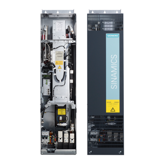
Device overview 2.2 Overview of the chassis units Overview of the chassis units Figure 2-1 Overview of the chassis units Inverter chassis units Operating Instructions, 07/2016, A5E00331449A... -
Page 27: Overview Of The Power Modules
Device overview 2.3 Overview of the Power Modules Overview of the Power Modules Figure 2-2 Overview of the Power Modules Inverter chassis units Operating Instructions, 07/2016, A5E00331449A... -
Page 28: Applications, Features
As a result, SINAMICS G130 chassis units are a cost-effective drive solution for all types of industrial applications that involve moving, conveying, pumping, compressing, or extracting solids, liquids, or gases. - Page 29 Device overview 2.4 Applications, features Quality SINAMICS G130 built-in units are manufactured to meet high standards of quality and exacting demands. This results in a high level of reliability, availability, and functionality for our products. The development, design, and manufacturing processes, as well as order processing and the logistics supply center have been certified to DIN ISO 9001 by an independent authority.
-
Page 30: Wiring Principle
Device overview 2.5 Wiring principle Wiring principle Wiring principle for SINAMICS G130 Figure 2-3 Wiring principle for SINAMICS G130 Inverter chassis units Operating Instructions, 07/2016, A5E00331449A... -
Page 31: Type Plate
Device overview 2.6 Type plate Type plate Specifications on the type plate Figure 2-4 Type plate of built-in unit Inverter chassis units Operating Instructions, 07/2016, A5E00331449A... - Page 32 Device overview 2.6 Type plate Type plate specifications (from type plate above) Position Specification Value Explanation ① Input 3 AC Three-phase connection 380 ... 480 V Rated input voltage 775 A Rated input current ② Output 3 AC Three-phase connection 0 ...
-
Page 33: Mechanical Installation
Mechanical installation Chapter content This chapter provides information on the following: ● The conditions for installing the chassis units and optional components. ● The preparations for installing the chassis units and optional components. Transportation and storage Transport WARNING Danger to life due to incorrectly transporting the unit The unit can tip over if you transport it incorrectly –... - Page 34 • If you fail to contact them immediately, you may lose your right to claim compensation for the defects and damage. • If necessary, you can request the support of your local Siemens office. Storage The devices must be stored in clean, dry rooms. Temperatures between -25° C and +55° C are permissible (class 1K4 according to EN 60721-3-1).
-
Page 35: Assembly
Mechanical installation 3.3 Assembly Assembly WARNING Danger to life if the general safety instructions and remaining risks are not carefully observed If the general safety instructions and remaining risks are not observed, accidents can occur involving severe injuries or death. •... -
Page 36: Unpacking
Mechanical installation 3.3 Assembly Installation is realized in accordance with the dimension drawings supplied. The clearance to be maintained around the units is also specified on the dimension drawings. The cooling air for the power unit is drawn from the lower part of the device. The warmed air is expelled through the heat sink. -
Page 37: Power Module
Mechanical installation 3.4 Power Module Power Module Description The Power Module is the power unit of an AC-AC converter. Line or motor-side components can be added to create a converter system. If required (e.g., for braking operation), a Braking Module can also be installed in the DC link of the converter. A slot is provided in the Power Module for this purpose. -
Page 38: Dimension Drawings
Mechanical installation 3.4 Power Module 3.4.1 Dimension drawings Dimension drawing frame size FX Table 3- 1 Dimension drawing frame size FX Front view Side view Inverter chassis units Operating Instructions, 07/2016, A5E00331449A... - Page 39 Mechanical installation 3.4 Power Module Dimension drawing, frame size GX Table 3- 2 Dimension drawing, frame size GX Front view Side view Inverter chassis units Operating Instructions, 07/2016, A5E00331449A...
- Page 40 Mechanical installation 3.4 Power Module Dimension drawing (frame size HX) Table 3- 3 Dimension drawing (frame size HX) Side view Rear view Inverter chassis units Operating Instructions, 07/2016, A5E00331449A...
- Page 41 Mechanical installation 3.4 Power Module Dimension drawing (frame size JX) Table 3- 4 Dimension drawing (frame size JX) Side view Rear view Inverter chassis units Operating Instructions, 07/2016, A5E00331449A...
-
Page 42: Control Unit Cu320-2
Mechanical installation 3.5 Control Unit CU320-2 Control Unit CU320-2 Description The CU320-2 is the central Control Unit in which the closed-loop and open-loop control functions are implemented. WARNING Fire hazard due to overheating because of inadequate ventilation clearances Insufficient ventilation clearances result in overheating with danger to persons as a result of smoke and fire. -
Page 43: Tm31 Terminal Module
Mechanical installation 3.6 TM31 Terminal Module Note Installing the Control Unit With frame sizes FX and GX, the Control Unit is installed to the left of the Power Module. The required connection elements are supplied with the Power Module. With frame sizes HX and JX, the Control Unit is installed in the Power Module. Control Unit: Memory card The memory card contains the control software and parameters. - Page 44 Mechanical installation 3.6 TM31 Terminal Module Dimension drawing Figure 3-2 Dimension drawing of the TM31 Terminal Module Note Installation of the Terminal Module The TM31 is installed near the Power Module on a mounting rail, which must be provided by the customer.
-
Page 45: Smc30 Sensor Module
Mechanical installation 3.7 SMC30 Sensor Module SMC30 Sensor Module Description The SMC30 Sensor Module is a module for evaluating encoder signals. TTL/HTL encoders (with or without open-circuit monitoring) can be connected to the SMC30. The motor temperature can also be detected using KTY84-1C130 or PTC thermistors. WARNING Fire hazard due to overheating because of inadequate ventilation clearances Insufficient ventilation clearances result in overheating with danger to persons as a result of... - Page 46 Mechanical installation 3.7 SMC30 Sensor Module Note Installation of the Sensor Module The SMC30 is installed near the Power Module on a mounting rail, which must be provided by the customer. Inverter chassis units Operating Instructions, 07/2016, A5E00331449A...
-
Page 47: Electrical Installation
Electrical installation Chapter content This chapter provides information on the following: ● Establishing the electrical connections for the Power Module, the CU320-2 Control Unit, and the optional TM31 Terminal Module and SMC30 Sensor Module. ● Adjusting the fan voltage and the internal power supply in line with local conditions (supply voltage) ●... -
Page 48: Important Safety Precautions
• Before switching on the device, it should be formed after a storage time exceeding two years, see Chapter "Maintenance and servicing". NOTICE Only use original Siemens accessories To ensure that the entire system functions properly, you are advised to use the original Siemens accessories. -
Page 49: Introduction To Emc
Electrical installation 4.4 Introduction to EMC Introduction to EMC What is meant by EMC? Electromagnetic compatibility (EMC) describes the capability of an electrical device to function satisfactorily in an electromagnetic environment without itself causing interference unacceptable for other devices in the environment. EMC therefore represents a quality feature for the ●... - Page 50 Electrical installation 4.4 Introduction to EMC Noise emissions Product standard EN 61800–3 outlines the EMC requirements for variable-speed drive systems. It specifies requirements for converters with operating voltages of less than 1000 V. Different environments and categories are defined depending on where the drive system is installed.
-
Page 51: Emc-Compliant Design
Electrical installation 4.5 EMC-compliant design Table 4- 2 Definition of categories C1 ... C4 Definition of categories C1 ... C4 Category C1 Rated voltage <1000 V; unrestricted use in the first environment. Category C2 Rated voltage for stationary drive systems <1000 V; for use in the second environment. - Page 52 Electrical installation 4.5 EMC-compliant design Use anti-interference elements ● If relays, contactors, and inductive or capacitive loads are connected, the switching relays or contactors must be provided with anti-interference elements. Cable installation ● Cables that are subject to or sensitive to interference should be laid as far apart from each other as possible.
- Page 53 Electrical installation 4.5 EMC-compliant design I/O interfacing ● Create a low-impedance ground connection for additional cabinets, system components, and distributed devices with the largest possible cross-section (at least 16 mm²). ● Ground unused lines at one end in the cabinet. ●...
-
Page 54: Connection Overview
Electrical installation 4.6 Connection overview Connection overview Power Module, frame size FX Figure 4-3 Connection overview of Power Module, frame size FX (without front cover) Inverter chassis units Operating Instructions, 07/2016, A5E00331449A... - Page 55 Electrical installation 4.6 Connection overview Power Module (frame size GX) Figure 4-4 Connection overview of Power Module (frame size GX) (without front cover) Inverter chassis units Operating Instructions, 07/2016, A5E00331449A...
- Page 56 Electrical installation 4.6 Connection overview Power Module (frame size HX) Figure 4-5 Connection overview of Power Module (frame size HX) (without front cover) Inverter chassis units Operating Instructions, 07/2016, A5E00331449A...
- Page 57 Electrical installation 4.6 Connection overview Power Module (frame size JX) Figure 4-6 Connection overview of Power Module (frame size JX) (without front cover) Inverter chassis units Operating Instructions, 07/2016, A5E00331449A...
-
Page 58: Power Connections
Electrical installation 4.7 Power connections Power connections WARNING Danger to life through electric shock caused by interchanging or short-circuiting device connections Interchanging the line connections and motor connections or short-circuiting the DC-link connections will damage the device that can cause death or severe injuries. •... -
Page 59: Connection Cross-Sections, Cable Lengths
Cable lengths The maximum permissible cable lengths are specified for standard cable types or cable types recommended by SIEMENS. Longer cables can only be used after consultation. The listed cable length represents the actual distance between the converter and the motor, taking account factors such as parallel laying, current-carrying capacity, and the laying factor. -
Page 60: Connecting The Motor And Power Cables
4.7 Power connections Note Shielded cables The PROTOFLEX-EMV-3 PLUS shielded cable recommended by Siemens is the protective conductor and comprises three symmetrically-arranged protective conductors. The individual protective conductors must each be provided with cable eyes and be connected to ground. - Page 61 Electrical installation 4.7 Power connections Direction of motor rotation EN 60034-7 defines the two ends of an electric motor as follows: ● DE (Drive End): usually the drive end of the motor ● NDE (Non-Drive End): usually the non-drive end of the motor An electric motor will rotate clockwise if the shaft is turning clockwise when looking at the DE side.
-
Page 62: Dcps, Dcns Connection For A Dv/Dt Filter With Voltage Peak Limiter
Electrical installation 4.7 Power connections 4.7.4 DCPS, DCNS connection for a dV/dt filter with Voltage Peak Limiter Table 4- 5 DCPS, DCNS Frame size Connectable cross-section Terminal screw 1 x 70 mm² 1 x 70 mm² 1 x 185 mm² 2 x 185 mm²... - Page 63 Electrical installation 4.7 Power connections Note Fan transformer for 660 to 690 V 3 AC With the 660 V to 690 V 3 AC fan transformer, a jumper is inserted between the "600 V" terminal and "CON" terminal. The "600V" and "CON" terminals are for internal use. WARNING Danger of fire due to overheating resulting from insufficient device fan voltage If the terminals are not reconnected to correspond with the actual line voltage, overheating...
-
Page 64: Removing The Connection Clip To The Basic Interference Suppression Module For Operation On An Ungrounded Line Supply (It System)
Electrical installation 4.7 Power connections 4.7.6 Removing the connection clip to the basic interference suppression module for operation on an ungrounded line supply (IT system) If the built-in unit is operated from a non-grounded supply (IT system), the connection clip to the basic interference suppression module of the Power Module must be removed. - Page 65 Electrical installation 4.7 Power connections Figure 4-10 Removing the connection clip to the basic interference suppression module, frame size Inverter chassis units Operating Instructions, 07/2016, A5E00331449A...
- Page 66 Electrical installation 4.7 Power connections Figure 4-11 Removing the connection clip to the basic interference suppression module, frame size Inverter chassis units Operating Instructions, 07/2016, A5E00331449A...
- Page 67 Electrical installation 4.7 Power connections Figure 4-12 Removing the connection clip to the basic interference suppression module, frame size Inverter chassis units Operating Instructions, 07/2016, A5E00331449A...
- Page 68 Electrical installation 4.7 Power connections Figure 4-13 Removing the connection clip to the basic interference suppression module, frame size JX Inverter chassis units Operating Instructions, 07/2016, A5E00331449A...
-
Page 69: External 24 V Dc Supply
Electrical installation 4.8 External 24 V DC supply External 24 V DC supply Description An external 24 V DC supply is always recommended if communication and closed-loop control are to be independent of the supply system. An external auxiliary supply is particularly recommended for low-power lines susceptible to short-time voltage dips or power failures. -
Page 70: Drive-Cliq Wiring Diagram
Electrical installation 4.9 DRIVE-CLiQ wiring diagram DRIVE-CLiQ wiring diagram The diagram below shows the specifications for the DRIVE-CLiQ connections between the components. NOTICE Comply with connection specifications These specifications for the DRIVE-CLiQ connections should be observed, otherwise faults may occur during commissioning via STARTER or the AOP30 operator panel. Figure 4-14 DRIVE-CLiQ wiring diagram Inverter chassis units... -
Page 71: Signal Connections
Electrical installation 4.10 Signal connections 4.10 Signal connections 4.10.1 Power Module X9: Terminal block Table 4- 9 Terminal block X9 Terminal Function Technical data P24V External 24 V DC supply Voltage: 24 V DC (20.4 to 28.8 V) Current consumption: max. 4 A Reserved, do not use Reserved, do not use Control of the main contactor... - Page 72 Electrical installation 4.10 Signal connections WARNING Danger to life due to electric shock in the event of voltage flashovers at the temperature sensor Voltage flashovers in the signal electronics can occur in motors without safe electrical separation of the temperature sensors. •...
- Page 73 Electrical installation 4.10 Signal connections Note Safety Integrated Function Manual Detailed and comprehensive instructions and information for the Safety Integrated functions can be found in the associated Function Manual. This manual is available as additional documentation on the customer DVD supplied with the device. X42: Power supply for the Control Unit, Sensor Module and Terminal Module Table 4- 11 Terminal block X42...
- Page 74 Electrical installation 4.10 Signal connections WARNING Fire hazard due to overheating when permissible connection cable lengths are exceeded Excessively long connection cables connected to terminal strip X46 can cause components to overheat with the associated risk of fire and smoke. •...
-
Page 75: Control Unit Cu320-2 Dp
Electrical installation 4.10 Signal connections 4.10.2 Control Unit CU320-2 DP Connection overview Figure 4-15 Connection overview of the CU320-2 DP Control Unit (without cover) Inverter chassis units Operating Instructions, 07/2016, A5E00331449A... - Page 76 Electrical installation 4.10 Signal connections Figure 4-16 Interface X140 and measuring sockets T0 to T2 - CU320-2 DP (view from below) NOTICE Malfunctions or damage to the option board by inserting and withdrawing in operation Withdrawing and inserting the option board in operation can damage it or cause it to malfunction.
- Page 77 Electrical installation 4.10 Signal connections Connection example Figure 4-17 Connection example of CU320-2 DP Inverter chassis units Operating Instructions, 07/2016, A5E00331449A...
- Page 78 Electrical installation 4.10 Signal connections X100 to X103: DRIVE-CLiQ interface Table 4- 14 DRIVE-CLiQ interface X100 – X103 Signal name Technical data Transmit data + Transmit data - Receive data + Reserved, do not use Reserved, do not use Receive data - Reserved, do not use Reserved, do not use + (24 V)
- Page 79 Electrical installation 4.10 Signal connections X122: Digital inputs/outputs Table 4- 15 Terminal block X122 Designation Technical data DI 0 Voltage (max.): -3 ... +30 V DC Typical power consumption: 9 mA at 24 V DI 1 Electrical isolation: reference potential is terminal M1 DI 2 Level (with ripple) DI 3...
- Page 80 Electrical installation 4.10 Signal connections Note Ensuring the function of digital inputs An open input is interpreted as "low". Terminal M1 must be connected so that the digital inputs (DI) can function. This is achieved through one of the following measures: 1.
- Page 81 Electrical installation 4.10 Signal connections X132: Digital inputs/outputs Table 4- 16 Terminal block X132 Designation Technical data DI 4 Voltage (max.): -3 … +30 VDC Current consumption, typical: 9 mA at 24 V DI 5 Electrical isolation: The reference potential is terminal M2 DI 6 Level (including ripple) DI 7...
- Page 82 Electrical installation 4.10 Signal connections Note Ensuring the function of digital inputs An open input is interpreted as "low". To enable the digital inputs (DI) to function, terminal M2 must be connected. This is achieved through one of the following measures: 1.
- Page 83 Electrical installation 4.10 Signal connections X126: PROFIBUS connection The PROFIBUS is connected by means of a 9-pin SUB D socket (X126). The connections are electrically isolated. Table 4- 18 PROFIBUS interface X126 Signal name Meaning Range Not assigned M24_SERV Power supply for teleservice, ground RxD/TxD–P Receive/transmit data P (B) RS485...
- Page 84 Electrical installation 4.10 Signal connections Connectors The cables must be connected via PROFIBUS connectors as they contain the necessary terminating resistors. The figure below shows suitable PROFIBUS connectors with/without a PG/PC connector. PROFIBUS connector PROFIBUS connector without PG/PC connection with PG/PC connection 6ES7972-0BA42-0XA0 6ES7972-0BB42-0XA0 Bus terminating resistor...
- Page 85 Electrical installation 4.10 Signal connections PROFIBUS address switches The PROFIBUS address is set as a hexadecimal value via two rotary coding switches. Values between 0 ) and 127 ) can be set as the address. The upper rotary coding switch (H) is used to set the hexadecimal value for 16 and the lower rotary coding switch (L) is used to set the hexadecimal value for 16 Table 4- 19...
- Page 86 Electrical installation 4.10 Signal connections Note Address 126 is used for commissioning. Permitted PROFIBUS addresses are 1 ... 126. When several Control Units are connected to a PROFIBUS line, you set the addresses differently than for the factory setting. Each PROFIBUS address in a PROFIBUS line can only be assigned once.
- Page 87 Electrical installation 4.10 Signal connections X140: serial interface (RS232) The AOP30 operator panel for operating/parameterizing the device can be connected via the serial interface. The interface is located on the underside of the Control Unit. Table 4- 22 Serial interface (RS232) X140 Designation Technical data Receive data...
- Page 88 Electrical installation 4.10 Signal connections Note Using the measuring socket contacts The measuring socket contacts support commissioning and diagnostic functions. It must not be connected for normal operation. DIAG button The DIAG pushbutton is reserved for service functions. Slot for the memory card Figure 4-19 Slot for the memory card WARNING...
- Page 89 • Do not return the memory card as well, but rather keep it in a safe place so that it can be inserted in the replacement unit. Note Please note that only SIEMENS memory cards can be used to operate the Control Unit. Inverter chassis units Operating Instructions, 07/2016, A5E00331449A...
-
Page 90: Control Unit Cu320-2 Pn
Electrical installation 4.10 Signal connections 4.10.3 Control Unit CU320-2 PN Connection overview Figure 4-20 Connection overview of CU320-2 PN Control Unit (without cover) Inverter chassis units Operating Instructions, 07/2016, A5E00331449A... - Page 91 Electrical installation 4.10 Signal connections Figure 4-21 Interface X140 and measuring sockets T0 to T2 - CU320-2 PN (view from below) NOTICE Malfunctions or damage to the option board by inserting and withdrawing in operation Withdrawing and inserting the option board in operation can damage it or cause it to malfunction.
- Page 92 Electrical installation 4.10 Signal connections Connection example Figure 4-22 Connection example, CU320-2 PN Inverter chassis units Operating Instructions, 07/2016, A5E00331449A...
- Page 93 Electrical installation 4.10 Signal connections X100 to X103: DRIVE-CLiQ interface Table 4- 24 DRIVE-CLiQ interface X100 – X103 Signal name Technical data Transmit data + Transmit data - Receive data + Reserved, do not use Reserved, do not use Receive data - Reserved, do not use Reserved, do not use + (24 V)
- Page 94 Electrical installation 4.10 Signal connections X122: Digital inputs/outputs Table 4- 25 Terminal block X122 Designation Technical data DI 0 Voltage (max.): -3 ... +30 V DC Typical power consumption: 9 mA at 24 V DI 1 Electrical isolation: reference potential is terminal M1 DI 2 Level (with ripple) DI 3...
- Page 95 Electrical installation 4.10 Signal connections Note Ensuring the function of digital inputs An open input is interpreted as "low". Terminal M1 must be connected so that the digital inputs (DI) can function. This is achieved through one of the following measures: 1.
- Page 96 Electrical installation 4.10 Signal connections X132: Digital inputs/outputs Table 4- 26 Terminal block X132 Designation Technical data DI 4 Voltage (max.): -3 … +30 VDC Current consumption, typical: 9 mA at 24 V DI 5 Electrical isolation: The reference potential is terminal M2 DI 6 Level (including ripple) DI 7...
- Page 97 Electrical installation 4.10 Signal connections Note Ensuring the function of digital inputs An open input is interpreted as "low". To enable the digital inputs (DI) to function, terminal M2 must be connected. This is achieved through one of the following measures: 1.
- Page 98 Electrical installation 4.10 Signal connections X127: LAN (Ethernet) Table 4- 28 X127 LAN (Ethernet) Designation Technical data Ethernet transmit data + Ethernet transmit data - Ethernet receive data + Reserved, do not use Reserved, do not use Ethernet receive data - Reserved, do not use Reserved, do not use Connector type: RJ45 socket...
- Page 99 Electrical installation 4.10 Signal connections X140: serial interface (RS232) The AOP30 operator panel for operating/parameterizing the device can be connected via the serial interface. The interface is located on the underside of the Control Unit. Table 4- 30 Serial interface (RS232) X140 Designation Technical data Receive data...
- Page 100 Electrical installation 4.10 Signal connections Note Connection cables The PROFINET interfaces support Auto MDI(X). It is therefore possible to use both crossover and non-crossover cables to connect the devices. For diagnostic purposes, the two PROFINET interfaces are each equipped with a green and a yellow LED.
- Page 101 Electrical installation 4.10 Signal connections DIAG button The DIAG pushbutton is reserved for service functions. Slot for the memory card Figure 4-23 Slot for the memory card Inverter chassis units Operating Instructions, 07/2016, A5E00331449A...
- Page 102 • Do not return the memory card as well, but rather keep it in a safe place so that it can be inserted in the replacement unit. Note Please note that only SIEMENS memory cards can be used to operate the Control Unit. Inverter chassis units Operating Instructions, 07/2016, A5E00331449A...
-
Page 103: Tm31 Terminal Module
Electrical installation 4.10 Signal connections 4.10.4 TM31 Terminal Module Description The TM31 Terminal Module is a terminal extension board. The TM31 terminal Module can be used to increase the number of available digital/analog inputs/outputs within a drive system. Connection overview Figure 4-24 TM31 Terminal Module Inverter chassis units... - Page 104 Electrical installation 4.10 Signal connections Figure 4-25 Connection overview of TM31 Terminal Module Inverter chassis units Operating Instructions, 07/2016, A5E00331449A...
- Page 105 Electrical installation 4.10 Signal connections X500, X501: DRIVE-CLiQ interface Table 4- 34 DRIVE-CLiQ interface X500 and X501 Signal name Technical data Transmit data + Transmit data - Receive data + Reserved, do not use Reserved, do not use Receive data - Reserved, do not use Reserved, do not use + (24 V)
- Page 106 Electrical installation 4.10 Signal connections X520: 4 digital inputs Table 4- 36 Terminal block X520 Terminal Designation Technical data DI 0 Voltage: - 3 … +30 V Current consumption typical: 10 mA at 24 V DC DI 1 Input delay: DI 2 for "0"...
- Page 107 Electrical installation 4.10 Signal connections X530: 4 digital inputs Table 4- 37 Terminal block X530 Terminal Designation Technical data DI 4 Voltage: - 3 … +30 V Current consumption typical: 10 mA at 24 V DC DI 5 Input delay: DI 6 For "0"...
- Page 108 Electrical installation 4.10 Signal connections X521: 2 analog inputs (differential inputs) Table 4- 38 Terminal block X521 Terminal Designation Technical data AI 0+ The analog inputs can be toggled between current and voltage input using switches S5.0 and S5.1. AI 0- As voltage input: AI 1+ -10 ...
- Page 109 Electrical installation 4.10 Signal connections S5: Selector for voltage/current AI0, AI1 Table 4- 39 Selector for voltage/current S5 Switch Function S5.0 Selector voltage (V) / current (I) Al0 S5.1 Selector voltage (V) / current (I) Al1 Note Delivery condition When delivered, both switches are set to voltage measurement (switch set to "V"). X522: 2 analog outputs, temperature sensor connection Table 4- 40 Terminal block X522...
- Page 110 Electrical installation 4.10 Signal connections NOTICE Damage or malfunctions through impermissible voltage values If the back EMF is impermissible then damage and malfunctions may occur on the components. • The back EMF at the outputs may only be in the range between -15 V and +15 V. NOTICE Damage to motor in the event of incorrectly connected KTY temperature sensor If a KTY temperature sensor is connected with incorrect polarity, it is not possible to detect...
- Page 111 Electrical installation 4.10 Signal connections X541: 4 non-floating digital inputs/outputs Table 4- 42 Terminal strip X541 Terminal Designation Technical data Auxiliary voltage: Voltage: +24 V DC DI/DO 11 Max. total load current of +24 V auxiliary voltage for DI/DO 10 terminals X540 and X541 combined: 150 mA DI/DO 9 As input:...
- Page 112 Electrical installation 4.10 Signal connections X542: 2 relay outputs (two-way contact) Table 4- 43 Terminal block X542 Terminal Designation Technical data DO 0.NC Contact type: Changeover contact max. load current: DO 0.COM Max. switching voltage: 250 V . 30 V DO 0.NO Max.
-
Page 113: Sensor Module Cabinet-Mounted Smc30
DRIVE-CLiQ interface for evaluation purposes. In conjunction with SINAMICS G130 the following encoders can be connected to the SMC30 Sensor Module: ●... - Page 114 Electrical installation 4.10 Signal connections Table 4- 46 Specification of measuring systems that can be connected Parameters Designation Threshold Min. Max. Unit High signal level Hdiff (TTL bipolar at X520 or X521/X531) Low signal level Ldiff (TTL bipolar to X520 or X521/X531) High signal level High (HTL unipolar)
- Page 115 Electrical installation 4.10 Signal connections Figure 4-27 Position of the zero pulse to the track signals For encoders with a 5-V supply at X521/X531, the cable length is dependent on the encoder current (this applies cable cross-sections of 0.5 mm²): Figure 4-28 Signal cable length as a function of the encoder current consumption Inverter chassis units...
- Page 116 Electrical installation 4.10 Signal connections For encoders without Remote Sense the permissible cable length is restricted to 100 m (reason: the voltage drop depends on the cable length and the encoder current). Figure 4-29 SMC30 Sensor Module Inverter chassis units Operating Instructions, 07/2016, A5E00331449A...
-
Page 117: Connection
Electrical installation 4.10 Signal connections 4.10.5.2 Connection X500: DRIVE-CLiQ interface Table 4- 47 DRIVE-CLiQ interface X500 Signal name Technical data Transmit data + Transmit data - Receive data + Reserved, do not use Reserved, do not use Receive data - Reserved, do not use Reserved, do not use + (24 V) - Page 118 Electrical installation 4.10 Signal connections X520: Encoder connection 1 for HTL/TTL encoder with open-circuit monitoring Table 4- 49 Encoder connection X520 Signal name Technical data +Temp Temperature sensor connection KTY84- 1C130 / PT1000 / PTC Reserved, do not use Reserved, do not use P encoder 5 V/24 V Encoder supply P encoder 5 V/24 V...
- Page 119 Electrical installation 4.10 Signal connections NOTICE Device failure as a result of unshielded or incorrectly routed cables to temperature sensors Unshielded or incorrectly routed cables to temperature sensors can result in interference being coupled into the signal processing electronics from the power side. This can result in significant disturbance of all signals (fault messages) up to failure of individual components (destruction of the devices).
- Page 120 Electrical installation 4.10 Signal connections X521 / X531: Encoder connection 2 for HTL/TTL encoder with open-circuit monitoring Table 4- 50 Encoder connection X521 Terminal Signal name Technical data Incremental signal A Inverse incremental signal A Incremental signal B Inverse incremental signal B Reference signal R Inverse reference signal R CTRL...
- Page 121 Electrical installation 4.10 Signal connections WARNING Danger to life due to electric shock in the event of voltage flashovers at the temperature sensor Voltage flashovers in the signal electronics can occur in motors without safe electrical separation of the temperature sensors. •...
-
Page 122: Connection Examples
Electrical installation 4.10 Signal connections 4.10.5.3 Connection examples Connection example 1: HTL encoder, bipolar, without zero marker -> p0405 = 9 (hex) Figure 4-30 Connection example 1: HTL encoder, bipolar, without zero marker Connection example 2: TTL encoder, unipolar, without zero marker -> p0405 = A (hex) Figure 4-31 Connection example 2: TTL encoder, unipolar, without zero marker Inverter chassis units... -
Page 123: Tm54F Terminal Module
Electrical installation 4.10 Signal connections 4.10.6 TM54F Terminal Module The TM54F Terminal Module is a terminal expansion module with safe digital inputs and outputs for controlling the Safety Integrated Extended functions of SINAMICS. The TM54F provides 4 fail-safe digital outputs and 10 fail-safe digital inputs. A fail-safe digital output consists of a 24 V DC switching output, a ground switching output, and a digital input for checking the switching state. - Page 124 Electrical installation 4.10 Signal connections Inverter chassis units Operating Instructions, 07/2016, A5E00331449A...
-
Page 125: Chapter Content
Commissioning Chapter content This section provides information on the following: ● Initial commissioning of the chassis unit (initialization) with STARTER and AOP30 – Entering the motor data (drive commissioning) – Entering the most important parameters (basic commissioning), concluding with motor identification ●... -
Page 126: Starter Commissioning Tool
Commissioning 5.2 STARTER commissioning tool Important information prior to commissioning The built-in unit offers a varying number of signal interconnections depending on the additional modules connected. For the converter control to be able to process the signals correctly, several software settings must be made. During initial power-up of the Control Unit and during first commissioning, parameter macros are executed and the necessary settings made. - Page 127 Commissioning 5.2 STARTER commissioning tool Prerequisites for installing STARTER Hardware The following minimum requirements must be complied with: ● PG or PC ● Pentium III, at least 1 GHz, (> 1 GHz recommended) ● 1 GB work memory (2 GB recommended) ●...
-
Page 128: Installing Starter
Commissioning 5.2 STARTER commissioning tool 5.2.1 Installing STARTER STARTER is installed using the "setup" file on the customer DVD supplied. When you double-click the "Setup" file, the installation Wizard guides you through the process of installing STARTER. Note Installation time The installation time depends on the computer performance and from where the software is installed (e.g. -
Page 129: Procedure For Commissioning Via Starter
Commissioning 5.3 Procedure for commissioning via STARTER Operating area Explanation 1: Toolbars In this area, you can access frequently used functions via the icons. 2: Project navigator The elements and projects available in the project are displayed here. 3: Working area In this area, you can change the settings for the drive units. - Page 130 Commissioning 5.3 Procedure for commissioning via STARTER Accessing the STARTER project wizard Figure 5-2 Main screen of the STARTER parameterization and commissioning tool ⇒ Hide STARTER Getting Started commissioning drive using HTML Help > Close The online help can be permanently hidden by deselecting Options > Settings > Workbench >...
- Page 131 Commissioning 5.3 Procedure for commissioning via STARTER The STARTER project wizard Figure 5-3 STARTER project wizard ⇒ click Arrange drive units offline... in the STARTER project wizard. Figure 5-4 Create new project ⇒ Enter a project name and, if necessary, the author, memory location and a comment. ⇒...
- Page 132 Commissioning 5.3 Procedure for commissioning via STARTER Figure 5-5 Set up interface ⇒ Under Access point: select the interface corresponding to your device configuration from: ● Select the S7ONLINE access (STEP7), if the connection to the drive unit is established via PROFINET or PROFIBUS.
- Page 133 Commissioning 5.3 Procedure for commissioning via STARTER Figure 5-6 Setting the interface Note Precondition To parameterize the interface, you must install the appropriate interface card (e.g., PC Adapter (PROFIBUS) Inverter chassis units Operating Instructions, 07/2016, A5E00331449A...
- Page 134 Commissioning 5.3 Procedure for commissioning via STARTER Figure 5-7 Setting the interface - properties Note Activate PG/PC is the only master on the bus You must activate PG/PC is the only master on bus if no other master (PC, S7, etc.) is available on the bus.
- Page 135 Commissioning 5.3 Procedure for commissioning via STARTER Figure 5-8 Complete setting the interface ⇒ Click Continue > to set up a drive unit in the project wizard. Figure 5-9 Inserting the drive unit ⇒ Choose the following data from the list fields: Device: Sinamics Type: G130 CU320-2 DP or G130 CU320-2 PN Version: 4.8...
- Page 136 Commissioning 5.3 Procedure for commissioning via STARTER Figure 5-10 Drive unit inserted ⇒ Click Continue > A project summary is displayed. Figure 5-11 Summary ⇒ Click Complete to finish creating a new drive unit project. Inverter chassis units Operating Instructions, 07/2016, A5E00331449A...
-
Page 137: Configuring The Drive Unit
Commissioning 5.3 Procedure for commissioning via STARTER 5.3.2 Configuring the drive unit In the project navigator, open the component that contains your drive unit. Figure 5-12 Project navigator – configuring the drive unit ⇒ In the project navigator, click the plus sign next to the drive unit that you want to configure. The plus sign becomes a minus sign and the drive unit configuration options are displayed as a tree below the drive unit. - Page 138 Commissioning 5.3 Procedure for commissioning via STARTER Configuring the drive unit Figure 5-13 Configuring the drive unit ⇒ Under Connection voltage, choose the correct voltage. Under Cooling method: choose the correct cooling method for your drive unit. Note Make a pre-selection In this step, you make a preliminary selection of the chassis units.
- Page 139 Commissioning 5.3 Procedure for commissioning via STARTER Selecting options Figure 5-14 Selecting options ⇒ From the combination box Options selection: select the options belonging to your drive unit by clicking on the corresponding check box. NOTICE Damage to the sine-wave filter if it is not activated during commissioning The sine-wave filter may be damaged if it is not activated during commissioning.
- Page 140 Commissioning 5.3 Procedure for commissioning via STARTER NOTICE Damage to the du/dt filter if it is not activated during commissioning The du/dt filter may be damaged if it is not activated during commissioning. • Activate the du/dt filter during commissioning by activating the appropriate checkbox (option DU/DT).
- Page 141 Commissioning 5.3 Procedure for commissioning via STARTER Selecting the control structure Figure 5-15 Selecting the control structure Inverter chassis units Operating Instructions, 07/2016, A5E00331449A...
- Page 142 Commissioning 5.3 Procedure for commissioning via STARTER ⇒ Select the corresponding settings for the closed-loop control structure: ● Function modules: – Technology controller – Extended messages/monitoring ● Control: – n/M control + U/f control, I/f control – U/f control ● Control mode: Depending on the selected control, you can select from one of the following open- loop/closed-loop control modes: –...
- Page 143 Commissioning 5.3 Procedure for commissioning via STARTER Configuring the drive unit properties Figure 5-16 Configuring the drive unit properties ⇒ Under Standard:, choose the appropriate standard for your motor, whereby the following is defined: ● IEC motor (50 Hz, SI unit): Line frequency 50 Hz, motor data in kW ●...
- Page 144 Commissioning 5.3 Procedure for commissioning via STARTER Selecting a standard motor type from a list Figure 5-17 Configuring a motor – selecting the motor type, selecting a standard motor from a list ⇒ Under Motor name: enter a name for the motor. ⇒...
- Page 145 Commissioning 5.3 Procedure for commissioning via STARTER Configuring the motor – Selecting the type of connection Figure 5-18 Configuring the motor – Selecting the type of connection ⇒Under Connection type:, select whether the motor is connected in a star or delta connection.
- Page 146 Commissioning 5.3 Procedure for commissioning via STARTER Selecting the motor type by entering the motor data Figure 5-19 Configuring the motor – Selecting the motor type ⇒ Under Motor name: enter a name for the motor. ⇒ select Enter motor data ⇒...
- Page 147 Commissioning 5.3 Procedure for commissioning via STARTER Note Commissioning of an induction motor The steps described below also apply to commissioning an induction motor. When commissioning a permanent-magnet synchronous motor, there are a few special conditions that apply, which are detailed in a separate chapter (see "Setpoint channel and closed-loop control / permanent-magnet synchronous motors").
- Page 148 Commissioning 5.3 Procedure for commissioning via STARTER Note Entering equivalent circuit diagram data You should only activate the Enter optional equivalent circuit diagram data if the data sheet with equivalent circuit diagram data is available. If any data is missing, an error message will be output when the system attempts to load the drive project to the target system.
- Page 149 Commissioning 5.3 Procedure for commissioning via STARTER Configuring the motor – Entering the equivalent circuit diagram data Figure 5-22 Entering equivalent circuit diagram data ⇒ Select one of the equivalent circuit diagram data representations: ● Physical system of units The equivalent circuit diagram data are shown in the form of physical units. ●...
- Page 150 Commissioning 5.3 Procedure for commissioning via STARTER Calculating the motor/controller data Figure 5-23 Calculating the motor/controller data ⇒ In Calculation of the motor/controller data, select the appropriate default settings for your device configuration. Note Manual input of the equivalent circuit diagram data If the equivalent circuit diagram data was entered manually (see "Entering the equivalent circuit diagram data"), then the motor/controller data should be calculated without calculating the equivalent circuit diagram data.
- Page 151 Commissioning 5.3 Procedure for commissioning via STARTER Configuring the motor holding brake Figure 5-24 Configuring the motor holding brake ⇒ Under Holding brake configuration: choose the appropriate setting for your device configuration: ● 0: No motor holding brake being used ●...
- Page 152 Commissioning 5.3 Procedure for commissioning via STARTER Entering the encoder data (option: SMC30 Sensor Module) Note Entering the encoder data If you specified the SMC30 Sensor Module when choosing the options, the Following input screen is displayed in which you can enter the encoder data. Figure 5-25 Entering the encoder data ⇒...
- Page 153 Figure 5-26 Entering encoder data – User-defined encoder data ⇒ Select the measuring system. You can choose the following encoders in conjunction with SINAMICS G130: ● HTL ● TTL ⇒ Enter the required encoder data. ⇒ under the Details tab, special encoder properties can be set, for example, gear ratio, fine resolution, inversion, measuring gear position tracking.
- Page 154 Commissioning 5.3 Procedure for commissioning via STARTER NOTICE Material damage when selecting the incorrect encoder supply voltage Once the encoder has been commissioned, the supply voltage (5/24 V) set for the encoder is activated on the SMC30 Module. If a 5 V encoder is connected and the supply voltage has not been set correctly, the encoder may be damaged.
- Page 155 Motorized potentiometer Fixed setpoint Note Use of CDS0 With SINAMICS G130, only CDS0 is normally used as a default setting for the command and setpoint sources. Make sure that the selected default setting is compatible with the actual system configuration.
- Page 156 Commissioning 5.3 Procedure for commissioning via STARTER Selecting drive functions Figure 5-28 Selecting drive functions ⇒ Select the required data: ● Technological application: – "(0) Standard drive (VECTOR)" Edge modulation is not enabled. The dynamic voltage reserve is increased (10 V), which reduces the maximum output voltage.
- Page 157 Commissioning 5.3 Procedure for commissioning via STARTER – "(4) Dynamic response in the field-weakening range" Space vector modulation with overmodulation is enabled. The dynamic voltage reserve is increased (30 V), which reduces the maximum output voltage. – "(5) Start-up with high break loose torque" This selection is suitable for speed-controlled start-up with sensorless vector control.
- Page 158 ● 2: Standard telegram 2, PZD-4/4 ● 3: Standard telegram 3, PZD-5/9 ● 4: Standard telegram 4, PZD-6/14 ● 20: SIEMENS telegram 20, PZD-2/6 ● 220: SIEMENS telegram 220, PZD-10/10 ● 352: SIEMENS telegram 352, PZD-6/6 ● 999: Free telegram configuration with BICO (default setting) ⇒...
- Page 159 Commissioning 5.3 Procedure for commissioning via STARTER Entering important parameters Figure 5-30 Important parameters ⇒ Enter the required parameter values. Note Tooltips STARTER provides tool tips if you position your cursor on the required field without clicking in the field. ⇒...
- Page 160 Commissioning 5.3 Procedure for commissioning via STARTER Web server Figure 5-31 Web server ⇒ Configure the web server. The web server is already active in the factory settings. Activate and deactivate the web server under Activate web server. Select Only allow access via secure connection (https) if necessary. Note Industrial Security Observe the notes on industrial security.
- Page 161 Commissioning 5.3 Procedure for commissioning via STARTER Summary of the drive unit data Figure 5-32 Summary of the drive unit data ⇒ You can use the Copy to clipboard function to copy the summary of the drive unit data displayed on the screen to a word processing program for further use. ⇒...
-
Page 162: Transferring The Drive Project
Commissioning 5.3 Procedure for commissioning via STARTER 5.3.3 Transferring the drive project You have created a project and saved it to your hard disk. You now have to transfer your project configuration data to the drive unit. Specifying the online access point To connect to the target system, the chosen access point must be specified. - Page 163 Commissioning 5.3 Procedure for commissioning via STARTER Specify access point: ● Select S7ONLINE access for a device, if the connection to the programming device or PC is established via PROFINET or PROFIBUS. ● Select DEVICE access for a device if the connection to the programming device or PC is established via the Ethernet interface.
-
Page 164: Commissioning With Starter Via Ethernet
Commissioning 5.3 Procedure for commissioning via STARTER Results of the previous steps ● You have created a drive unit project offline using STARTER. ● You have saved the project data to the hard disk on your PC. ● You have transferred the project data to the drive unit. ●... - Page 165 Commissioning 5.3 Procedure for commissioning via STARTER STARTER via Ethernet (example) Figure 5-34 STARTER via Ethernet (example) Procedure for establishing online operation via Ethernet 1. Install the Ethernet interface in the PG/PC according to the manufacturer's specifications. 2. Set the IP address of the Ethernet interface in Windows. –...
- Page 166 Commissioning 5.3 Procedure for commissioning via STARTER 7. Set the IP address of the PG/PC access interface to the Control Unit to 169.254.11.1 and the subnet mask to 255.255.0.0. Figure 5-35 Internet Protocol (TCP/IP) properties 8. Click "OK" and close the Windows-specific window of the network connections. Assigning the IP address and the name via STARTER, "Accessible nodes"...
- Page 167 Commissioning 5.3 Procedure for commissioning via STARTER 6. The SINAMICS drive object is detected and displayed as a bus node with IP address 169.254.11.22 and without name. Figure 5-36 Accessible nodes 7. Mark the bus node entry and select the displayed menu item "Edit Ethernet node" with the right mouse button.
- Page 168 Commissioning 5.3 Procedure for commissioning via STARTER Note Naming devices ST (Structured Text) conventions must be satisfied for the name assignment of IO devices in Ethernet (SINAMICS components). The names must be unique within Ethernet. Rules for assigning names: • Other than "-" and ".", no special characters (such as accented characters, spaces, brackets) are permitted in the name of an IO device.
- Page 169 Commissioning 5.3 Procedure for commissioning via STARTER 11.The SINAMICS drive is displayed as drive object in the project navigator. 12.You can now configure the drive unit (see Chapter "Configuring the drive unit"). Note Storage location of the IP address The IP address and device name are stored on the memory card of the Control Unit (non- volatile).
-
Page 170: The Aop30 Operator Panel
Commissioning 5.4 The AOP30 operator panel The AOP30 operator panel Description An optional operator panel for operating, monitoring, and commissioning purposes is available. It has the following features: ● Graphic-capable, back-lit LCD for plain-text display and a "bar-type display" for process variables ●... -
Page 171: First Commissioning With The Aop30
Commissioning 5.5 First commissioning with the AOP30 First commissioning with the AOP30 5.5.1 First commissioning Start screen When the system is switched on for the first time, the Control Unit is initialized automatically. The following screen is displayed: Figure 5-39 Initial screen When the system boots up, the parameter descriptions are loaded into the operating field from the CompactFlash card. - Page 172 Commissioning 5.5 First commissioning with the AOP30 Selecting the language When the system is first booted up, a screen for selecting the language appears. You can select the language in the dialog screen. To change the language, choose <F2> or <F3>.
-
Page 173: Basic Commissioning
Commissioning 5.5 First commissioning with the AOP30 5.5.2 Basic commissioning Entering the motor data During initial commissioning, you have to enter motor data using the operator panel. Use the data shown on the motor type plate. Figure 5-41 Example of a motor type plate Table 5- 1 Motor data Parameter no. - Page 174 Commissioning 5.5 First commissioning with the AOP30 Basic commissioning: Selecting the motor type and entering the motor data You can select the motor standard and type in the dialog screen. The following is defined for the motor stand- ard: 0: Line frequency 50 Hz, motor data in kW 1: Line frequency 60 Hz, motor data in hp The corresponding motor is selected for the motor type.
- Page 175 Commissioning 5.5 First commissioning with the AOP30 Note Selecting the motor type The selection of the motor type pre-assigns specific motor parameters and optimizes the operating characteristics and behavior. Details are described in the List Manual in the p0300 parameter. Note Selection of a list motor (p0300 ≥...
- Page 176 Commissioning 5.5 First commissioning with the AOP30 Predefined encoders can be easily set by selecting parameter p0400 (encoder type selection): 3001: 1024 HTL A/B R at X521/X531 3002: 1024 TTL A/B R at X521/X531 3003: 2048 HTL A/B R at X521/X531 3005: 1024 HTL A/B at X521/X531 3006:...
- Page 177 Commissioning 5.5 First commissioning with the AOP30 Table 5- 3 Meaning of the bit settings for p0405 Meaning Value 0 Value 1 Signal Unipolar Bipolar Level Track monitoring None A/B>< -A/B Zero pulse 24 V unipolar Same as A/B track Switching threshold High Pulse/direction...
- Page 178 Commissioning 5.5 First commissioning with the AOP30 Basic commissioning: Entering the basic parameters Entering the basic commissioning parame- ters: If a sine-wave filter is connected, it must be activated in p0230 (p0230 = 3/4). Otherwise, it could be damaged. p0700: Preset command source 1: PROFIdrive 2: TM31 terminals 3: CU terminals...
- Page 179 • du/dt filter compact plus Voltage Peak Limiter: p0230 = 2 • du/dt filter plus Voltage Peak Limiter p0230 = 2 • Siemens sine-wave filter: p0230 = 3 When p0230 = 4 "External sine-wave filter", a separate sine-wave filter can be entered. An input mask for specific filter data then appears.
- Page 180 Commissioning 5.5 First commissioning with the AOP30 Basic commissioning: Motor identification Selecting motor identification To navigate through the selection fields, choose <F2> or <F3>. To activate a selection, choose <F5>. Stationary measurement increases the con- trol performance, as this minimizes devia- tions in the electrical characteristic values due to variations in material properties and manufacturing tolerances.
- Page 181 Commissioning 5.5 First commissioning with the AOP30 WARNING Danger to life if the motor unexpectedly moves during motor identification in the rotating mode When selecting motor identification with optimization in the rotating mode, after commissioning, the drive initiates that the motor rotates with speeds that can reach the maximum motor speed.
-
Page 182: Status After Commissioning
Commissioning 5.6 Status after commissioning Status after commissioning LOCAL mode (control via operator panel) ● You switch to LOCAL mode by pressing the "LOCAL/REMOTE" key. ● Control (ON/OFF) is carried out via the "ON" and "OFF" keys. ● You can specify the setpoint using the "increase" and "decrease" keys or by entering the appropriate numbers using the numeric keypad. -
Page 183: Commissioning An Encoder With Gear Factor
Commissioning 5.7 Commissioning an encoder with gear factor Commissioning an encoder with gear factor Description When encoders are commissioned (p0010 = 4), a gearbox must be parameterized by means of parameters p0432 (numerator), p0433 (denominator), and p0410 (sign). To ensure that the commutation position can be accurately determined from the encoder angle, the following applies: = number of poles •... - Page 184 Commissioning 5.8 Parameter reset to factory settings Parameter reset via STARTER With STARTER, the parameters are reset in online mode. The required steps are described below: Step Selection in toolbar Choose Project > Connect to target system Click the drive unit whose parameters you want to reset to the factory settings and click Restore factory settings icon in the toolbar.
-
Page 185: Chapter Content
Operation Chapter content This chapter provides information on the following: ● Basic information about the drive system ● Command source selection via - PROFIdrive - terminal block TM31 - terminal block CU320 ● Setpoint input via - PROFIdrive - Analog inputs - Motorized potentiometer - Fixed setpoints ●... -
Page 186: General Information About Command And Setpoint Sources
4 default settings are available for selecting the command sources and 4 for selecting the setpoint sources for the SINAMICS G130. The choice "no selection" is also available; if selected, no default settings are applied for the command and setpoint sources. -
Page 187: Basic Information About The Drive System
Operation 6.3 Basic information about the drive system Basic information about the drive system 6.3.1 Parameters Overview The drive is adapted to the relevant drive task by means of parameters. Each parameter is identified by a unique parameter number and by specific attributes (e.g. read, write, BICO attribute, group attribute, and so on). - Page 188 Operation 6.3 Basic information about the drive system Parameter categories The parameters for the individual drive objects (see "Drive objects") are categorized according to data sets as follows (see "Operation/data sets"): ● Data-set-independent parameters These parameters exist only once per drive object. ●...
- Page 189 Operation 6.3 Basic information about the drive system Figure 6-2 Parameter categories Inverter chassis units Operating Instructions, 07/2016, A5E00331449A...
-
Page 190: Drive Objects
Operation 6.3 Basic information about the drive system 6.3.2 Drive objects A drive object is a self-contained software function with its own parameters and, if necessary, its own faults and alarms. Drive objects can be provided as standard (e.g. I/O evaluation), or you can add single (e.g. - Page 191 Operation 6.3 Basic information about the drive system Properties of a drive object ● Separate parameter space ● Separate window in STARTER ● Separate fault/alarm system ● Separate PROFIdrive telegram for process data Configuring drive objects When you commission the system for the first time using the STARTER tool, you will use configuration parameters to set up the software-based "drive objects"...
-
Page 192: Data Sets
Operation 6.3 Basic information about the drive system 6.3.3 Data sets Description For many applications, it is beneficial if more than one parameter can be changed simultaneously by means of one external signal during operation/when the system is ready for operation. This can be carried out using indexed parameters, whereby the parameters are grouped together in a data set according to their functionality and indexed. - Page 193 Operation 6.3 Basic information about the drive system Table 6- 1 Command data set: selection and display Select bit 1 Select bit 0 Display p0811 p0810 selected (r0836) active (r0050) If a command data set, which does not exist, is selected, the current data set remains active. Figure 6-4 Example: Switching between command data set 0 and 1 DDS: Drive data set...
- Page 194 Operation 6.3 Basic information about the drive system One drive object can manage up to 32 drive data sets. The number of drive data sets is configured with p0180. Binector inputs p0820 to p0824 are used to select a drive data set. They represent the number of the drive data set (0 to 31) in binary format (where p0824 is the most significant bit).
- Page 195 Operation 6.3 Basic information about the drive system MDS: Motor data set A motor data set contains various adjustable parameters describing the connected motor for the purpose of configuring the drive. It also contains certain display parameters with calculated data. ●...
- Page 196 Operation 6.3 Basic information about the drive system Copying the command data set (CDS) Set parameter p0809 as follows: 1. p0809[0] = number of the command data set to be copied (source) 2. p0809[1] = number of the command data to which the data is to be copied (target) 3.
-
Page 197: Bico Technology: Interconnecting Signals
Operation 6.3 Basic information about the drive system Parameters Power Module data sets (PDS) number • p0120 Motor data sets (MDS) number • p0130 Copy motor data set (MDS) • p0139[0...2] Encoder data sets (EDS) number • p0140 Command data set (CDS) number •... - Page 198 Operation 6.3 Basic information about the drive system Binectors, BI: binector input, BO: Binector output A binector is a digital (binary) signal without a unit which can assume the value 0 or 1. Binectors are subdivided into binector inputs (signal sink) and binector outputs (signal source).
- Page 199 Operation 6.3 Basic information about the drive system The following information is required in order to connect a binector/connector input to a binector/connector output: Parameter number, bit number, and drive object ID • Binectors: Parameter number and drive object ID •...
- Page 200 Operation 6.3 Basic information about the drive system Internal encoding of the binector/connector output parameters The internal codes are needed, for example, to write BICO input parameters via PROFIdrive. Figure 6-6 Internal encoding of the binector/connector output parameters Example 1: interconnecting digital signals Suppose you want to operate a drive via terminals DI 0 and DI 1 on the Control Unit using jog 1 and jog 2.
- Page 201 Operation 6.3 Basic information about the drive system Example 2: connection of OC/OFF3 to several drives The OFF3 signal is to be connected to two drives via terminal DI 2 on the Control Unit. Each drive has a binector input 1. OFF3 and 2. OFF3. The two signals are processed via an AND gate to STW1.2 (OFF3).
- Page 202 Operation 6.3 Basic information about the drive system Binector-connector converters and connector-binector converters Binector-connector converter ● Several digital signals are converted to a 32-bit integer double word or to a 16-bit integer word. ● p2080[0...15] BI: PROFIdrive PZD send bit-serial Connector-binector converter ●...
-
Page 203: Propagation Of Faults
Operation 6.3 Basic information about the drive system 6.3.5 Propagation of faults Forwarding faults to the Control Unit In the case of faults that are, for example, triggered by the Control Unit or a Terminal Module, central functions of the drive are also often affected. As a result of propagation, faults that are triggered by one drive object are therefore forwarded to other drive objects. -
Page 204: Command Sources
Operation 6.4 Command sources Command sources 6.4.1 "PROFIdrive" default setting Preconditions ● The Power Module and the Control Unit have been correctly installed. ● The "PROFIdrive" default setting was chosen during commissioning: "PROFIdrive" • STARTER (p0700): "1: G130 PROFIdrive" • AOP30 (p0700): Command sources Figure 6-9 Command sources –... - Page 205 Operation 6.4 Command sources CU320 terminal assignment with "PROFIdrive" default setting When you choose the "PROFIdrive" default setting, use the following terminal assignment for the Control Unit: Figure 6-10 Terminal assignment, Control Unit with the "PROFIdrive" default setting Control word 1 The bit assignment for control word 1 is described in "Description of the control words and setpoints".
-
Page 206: Tm31 Terminals" Default Setting
Operation 6.4 Command sources 6.4.2 "TM31 terminals" default setting Preconditions ● The Power Module, Control Unit and TM31 have been correctly installed. ● The "TM31 terminals" default setting was chosen during commissioning: "TM31 terminals" • STARTER (p0700): "2: TM31 terminals" •... - Page 207 Operation 6.4 Command sources TM31 terminal assignment with "TM31 terminals" default setting When you choose the "TM31 terminals" default setting, the terminal assignment for TM31 is as follows: Figure 6-12 TM31 terminal assignment with "TM31 terminals" default setting Changing over the command source If necessary, the command source can be changed over using the LOCAL/REMOTE key on the AOP30.
-
Page 208: Cu Terminals" Default Setting
Operation 6.4 Command sources 6.4.3 "CU terminals" default setting Preconditions ● The Power Module and the Control Unit have been correctly installed. ● The "CU terminals" default setting was chosen during commissioning: "CU terminals" • STARTER (p0700): "3: CU terminals" •... - Page 209 Operation 6.4 Command sources Terminal assignment, Control Unit with "CU terminals" default setting When you choose the "CU terminals" default setting, use the following terminal assignment for the Control Unit: Figure 6-14 Terminal assignment, Control Unit with "CU terminals" default setting Changing over the command source If necessary, the command source can be changed over using the LOCAL/REMOTE key on the AOP30.
-
Page 210: Profidrive+Tm31" Default Setting
Operation 6.4 Command sources 6.4.4 "PROFIdrive+TM31" default setting Preconditions ● The Power Module, Control Unit, TM31 and PROFIBUS have been correctly installed. ● The "PROFIdrive+TM31" default setting was chosen during commissioning: "PROFIdrive+TM31" • STARTER (p0700): "4: PROFIdrive+TM31" • AOP30 (p0700): Command sources Figure 6-15 Command sources - AOP30 <->... - Page 211 Operation 6.4 Command sources TM31 terminal assignment with "PROFIdrive+TM31" default setting Figure 6-16 TM31 terminal assignment with "PROFIdrive+TM31" default setting Changing over the command source If necessary, the command source can be changed over using the LOCAL/REMOTE key on the AOP30. Inverter chassis units Operating Instructions, 07/2016, A5E00331449A...
-
Page 212: Setpoint Sources
Operation 6.5 Setpoint sources Setpoint sources 6.5.1 Analog inputs Description The customer terminal block TM31 features two analog inputs for specifying setpoints for current or voltage signals. In the factory setting, analog input 0 (terminal X521:1/2) is used as a voltage input in the range 0 to 10 V. - Page 213 Operation 6.5 Setpoint sources Parameter Actual input voltage/current • r4052 Analog inputs smoothing time constant • p4053 Current referenced input value • r4055 Analog inputs type • p4056 Analog inputs, characteristic value x1 • p4057 Analog inputs, characteristic value y1 •...
-
Page 214: Motorized Potentiometer
Operation 6.5 Setpoint sources F3505 – Fault: "Analog input wire break" This fault is triggered when the analog input type (p4056) is set to 3 (4 ... 20 mA with open- circuit monitoring) and the input current of 2 mA has been undershot. The fault value can be used to determine the analog input in question. -
Page 215: Fixed Speed Setpoints
Operation 6.5 Setpoint sources Signal flow diagram Figure 6-18 Signal flow diagram: Motorized potentiometer Function diagram FD 3020 Motorized potentiometer Parameter Motorized potentiometer, configuration • p1030 Motorized potentiometer, maximum speed • p1037 Motorized potentiometer, minimum speed • p1038 Motorized potentiometer, ramp-up time •... - Page 216 Operation 6.5 Setpoint sources Precondition The default setting for the fixed speed setpoints was chosen during commissioning: "Fixed setpoint" • STARTER (p1000): "4: Fixed setpoint" • AOP30 (p1000): Signal flow diagram Figure 6-19 Signal flow diagram: Fixed speed setpoints Function diagram FP 3010 Fixed speed setpoints Parameter...
-
Page 217: Communication According To Profidrive
Operation 6.6 Communication according to PROFIdrive Communication according to PROFIdrive 6.6.1 General information PROFIdrive V4.1 is the PROFIBUS and PROFINET profile for drive technology with a wide range of applications in production and process automation. PROFIdrive is independent of the bus system used (PROFIBUS, PROFINET). Note References PROFIdrive for drive technology is described in the following document:... - Page 218 ● Isochronous mode Interface IF1 and IF2 The Control Unit can communicate via two different interfaces (IF1 and IF2). Table 6- 7 Properties of IF1 and IF2 PROFIdrive and SIEMENS telegram Free telegram Isochronous mode Drive object types Can be used for...
-
Page 219: Application Classes
Operation 6.6 Communication according to PROFIdrive Note For additional information on the IF1 and IF2 interfaces, see section "Parallel operation of communication interfaces". 6.6.2 Application classes Description There are different application classes for PROFIdrive according to the scope and type of the application processes. -
Page 220: Cyclic Communication
Operation 6.6 Communication according to PROFIdrive Telegram Description Class 1 Class 3 Class 4 (p0922 = x) Speed setpoint, 32 bit with 2 position encoders, torque reduction and DSC Basic positioner with MDI, override and XIST_A Basic positioner in the MDI mode Speed setpoint, 32 bit with 2 position encoders, torque reduction and DSC, plus actual load, torque, power and current values... -
Page 221: Zsw1
Operation 6.6 Communication according to PROFIdrive 6.6.3.1 Telegrams and process data General information Selecting a telegram via CU parameter p0922 determines which process data is transferred. From the perspective of the drive unit, the received process data comprises the receive words and the process data to be sent, the send words. - Page 222 Operation 6.6 Communication according to PROFIdrive Depending on the setting in p0922, the interface mode of the control and status word is automatically set: ● p0922 = 1, 352, 999: STW 1/STW 1: Interface Mode SINAMICS / MICROMASTER, p2038 = 0 ●...
-
Page 223: Structure Of The Telegrams
Operation 6.6 Communication according to PROFIdrive Note Easy method for creating extended telegram interconnections If p0922 = 999, a telegram can be selected in p2079. A telegram interconnection is automatically made and blocked. However, the telegram can also be extended. This is an easy method of creating extended telegram interconnections on the basis of existing telegrams. -
Page 224: Overview Of Control Words And Setpoints
Operation 6.6 Communication according to PROFIdrive 6.6.3.3 Overview of control words and setpoints Table 6- 10 Overview of control words and setpoints Abbreviation Description Parameter Function diagram STW1 Control word 1 (interface mode See table "Control word 1 (interface mode FP2442 SINAMICS, p2038 = 0) SINAMICS, p2038 = 0)"... -
Page 225: Acyclic Communication
Operation 6.6 Communication according to PROFIdrive Abbreviation Description Parameter Function diagram MELD_NAMUR VIK-NAMUR message bit bar r3113, see table "NAMUR message bit bar" WARN_CODE Alarm code r2132 FP8065 ERROR_CODE Error code r2131 FP8060 6.6.4 Acyclic communication Acyclic communication, as opposed to cyclic communication, means data is transferred only when an explicit request is made (e.g., in order to read and write parameters). - Page 226 Operation 6.6 Communication according to PROFIdrive Figure 6-20 Reading and writing data Characteristics of the parameter channel ● One 16-bit address exists for each parameter number and subindex. ● Simultaneous access by several additional PROFIBUS masters (master class 2) or PROFINET IO Supervisor (e.g., commissioning tool).
-
Page 227: Structure Of Requests And Responses
Operation 6.6 Communication according to PROFIdrive 6.6.4.1 Structure of requests and responses Structure of parameter request and parameter response Table 6- 12 Structure of the parameter request Parameter request Offset Values for Request header Request reference Request ID write access Axis Number of parameters only... - Page 228 Operation 6.6 Communication according to PROFIdrive Description of fields in the parameter request and response Table 6- 14 Fields in the parameter request and response Field Data type Values Comment Request reference Unsigned8 0x01 ... 0xFF Unique identification of the request/response pair for the master. The master changes the request reference with each new request.
- Page 229 Operation 6.6 Communication according to PROFIdrive Field Data type Values Comment Format Unsigned8 0x02 Data type integer8 0x03 Data type integer16 0x04 Data type integer32 0x05 Data type unsigned8 0x06 Data type unsigned16 0x07 Data type unsigned32 0x08 Data type floating point Other values See PROFIdrive profile V3.1 0x40...
- Page 230 Operation 6.6 Communication according to PROFIdrive Error values in parameter responses Table 6- 15 Error values in parameter responses Error Meaning Comment Additional value info 0x00 Illegal parameter number. Access to a parameter that does not exist. – 0x01 Parameter value cannot be changed. Modification access to a parameter value that cannot be Subindex changed.
- Page 231 Operation 6.6 Communication according to PROFIdrive Error Meaning Comment Additional value info 0x6B Write access for the enabled control- Write access is possible while the device is in the "Control- – ler. ler enable" state. Pay attention to the parameter attribute "changeable" in the SINAMICS S120/S150 List Manual (C1, C2, U, T).
- Page 232 Operation 6.6 Communication according to PROFIdrive Error Meaning Comment Additional value info 0x7A Parameter %s [%s]: Write access – – only in the commissioning state, data record base configuration (de- vice: p0009 = 4). 0x7B Parameter %s [%s]: Write access –...
-
Page 233: Determining The Drive Object Numbers
Operation 6.6 Communication according to PROFIdrive 6.6.4.2 Determining the drive object numbers Further information about the drive system (e.g., drive object numbers) can be determined as follows from parameters p0101, r0102 and p0107/r0107: 1. The value of parameter r0102 ("Number of drive objects") is read via a read request from drive object 1. - Page 234 Operation 6.6 Communication according to PROFIdrive Create request Table 6- 16 Parameter request Parameter request Offset Request header Request reference = 25 hex Request ID = 01 hex 0 + 1 Axis = 02 hex Number of parameters = 01 hex 2 + 3 Parameter address Attribute = 10 hex...
-
Page 235: Example 2: Writing Parameters (Multi-Parameter Request)
Operation 6.6 Communication according to PROFIdrive Information about the parameter response: ● Request reference mirrored: This response belongs to the request with request reference 25. ● Response identifier: 01 hex → Read request positive, values available starting from 1st value ●... - Page 236 Operation 6.6 Communication according to PROFIdrive Figure 6-21 Task description for multi-parameter request (example) Basic procedure 1. Create a request to write the parameters. 2. Invoke request. 3. Evaluate response. Create request Table 6- 18 Parameter request Parameter request Offset Request header Request reference = 40 hex Request ID = 02 hex...
- Page 237 Operation 6.6 Communication according to PROFIdrive Parameter request Offset Value = 02D2 hex Value = 0404 hex 2nd parameter value(s) Format = 07 hex Number of values = 01 hex 34 + 35 Value = 02D2 hex Value = 0405 hex 3rd parameter value(s) Format = 08 hex Number of values = 01 hex...
-
Page 238: Diagnostics Channels
Operation 6.6 Communication according to PROFIdrive Evaluate response. Table 6- 19 Parameter response Parameter response Offset Response Request reference mirrored = 40 hex Response ID = 02 hex header Axis mirrored = 02 hex Number of parameters = 04 hex Notes on the parameter response: ●... -
Page 239: Diagnostics Via Profinet
Operation 6.6 Communication according to PROFIdrive ● The drive transfers the messages in the sequence in which they occurred. ● The time stamps are generated from the higher-level controller when the messages are received ● The existing mechanisms of TIA and S7 Classic can be used. ●... - Page 240 Operation 6.6 Communication according to PROFIdrive Overview Figure 6-22 Components of a message Individual components of the Channel Diagnosis Data block can be included n times in a message. A precise explanation of these message components is subsequently provided: Inverter chassis units Operating Instructions, 07/2016, A5E00331449A...
- Page 241 Operation 6.6 Communication according to PROFIdrive Table 6- 20 Components of a message Designation Data For SINAMICS type/length Value Significance Channel Number 1 ... 399 Component number 0x8000 No component assignment Channel Properties .Type Bits 7 ... 0 No data length .Accumulative Bit 8 1 channel;...
-
Page 242: Diagnostics Via Profibus
Operation 6.6 Communication according to PROFIdrive System response - reading out diagnostics data The converter requests diagnostics data via "Read data set" (detailed information is provided in the PROFINET-IO specification (http://www.profibus.com)). Example: For example, a read record with index 0x800C can be used to read out diagnostics data from specific sub slots. - Page 243 Operation 6.6 Communication according to PROFIdrive The other diagnostics data (types) can be in any sequence. This is the reason that the following diagnostics data include a header: ● Identifier-related diagnostics ● Status messages/module status ● Channel-related diagnostics The diagnostic data type can be uniquely identified based on the header. Note The master must operate in the DPV1 mode.
- Page 244 Operation 6.6 Communication according to PROFIdrive Identifier-related diagnostics The identifier-related diagnostics provides a bit (KB_n) for each slot 1 allocated when configuring the device. If a diagnostics message is active at a slot, then it's KB_n = true. Octet Name Header- Block length (2 ...
- Page 245 Operation 6.6 Communication according to PROFIdrive Channel-related diagnostics Channel-related diagnostics encompasses the following data: Octet Name Header- 0 ... 63 (module number) including these bytes Byte x + 1 0 (no component assignment) x + 2 Message classes: 2 Undervoltage 3 Overvoltage 9 Error 16 Hardware/software error...
-
Page 246: Further Information About Profidrive Communication
Operation 6.6 Communication according to PROFIdrive The structure is as follows: Octet Name Header-Byte = 15 (block length) = 1 (diagnostics alarm) 0 ... 244 (slot number ≙ drive object) 0 ... 31 (sequence number) Add_Ack Alarm_Specifier DS0 (byte 0) DS0 (byte 1) DS0 (Byte 2) DS0 (byte 3) -
Page 247: Communication Via Profibus Dp
Operation 6.7 Communication via PROFIBUS DP Communication via PROFIBUS DP 6.7.1 PROFIBUS connection For more information about the PROFIBUS connection, see "Electrical installation". 6.7.2 Control via PROFIBUS Diagnostics LED "COM (PROFIdrive)" The PROFIBUS diagnostics LED is located on the front of the Control Unit. Its states are described in the following table. -
Page 248: Monitoring: Telegram Failure
Operation 6.7 Communication via PROFIBUS DP 6.7.3 Monitoring: Telegram failure Description In monitoring for telegram failure, two cases are possible: ● Telegram failure with a bus fault After a telegram failure and the additional monitoring time has elapsed (p2047), bit r2043.0 is set to "1"... -
Page 249: Further Information About Communication Via Profibus Dp
Operation 6.7 Communication via PROFIBUS DP 6.7.4 Further information about communication via PROFIBUS DP Further information about communication via PROFIBUS DP For more information about communication via PROFIBUS DP, refer to "Communication via PROFIBUS DP" in the accompanying "SINAMICS S120 Function Manual". Inverter chassis units Operating Instructions, 07/2016, A5E00331449A... -
Page 250: Communication Via Profinet Io
Operation 6.8 Communication via PROFINET IO Communication via PROFINET IO 6.8.1 Communication Board Ethernet CBE20 Description The CBE20 communication board must be inserted into the option slot of the Control Unit. Four Ethernet interfaces are available on the module. Diagnosis of the function mode and communication are possible via LEDs. - Page 251 Operation 6.8 Communication via PROFINET IO X1400 Ethernet interface Table 6- 22 Connector X1400, port 1 - 4 Signal name Technical data Receive data + Receive data - Transmit data + Reserved, do not use Reserved, do not use Transmit data - Reserved, do not use Reserved, do not use Screened backshell...
-
Page 252: Activating Online Operation: Starter Via Profinet Io
Operation 6.8 Communication via PROFINET IO 6.8.2 Activating online operation: STARTER via PROFINET IO Description Online operation with PROFINET IO is implemented using TCP/IP. Prerequisites ● STARTER Version 4.2 or higher ● Control unit CU320-2 PN or CBE20 STARTER via PROFINET IO (example) Figure 6-27 STARTER via PROFINET (example) Procedure, establishing online operation with PROFINET... - Page 253 Operation 6.8 Communication via PROFINET IO Set the IP address in Windows XP On the desktop, right-click on "Network environment" -> Properties -> double-click on Network card and choose -> Properties -> Internet Protocol (TCP/IP) -> Properties -> Enter the freely-assignable addresses. Figure 6-28 Properties of the Internet Protocol (TCP/IP) Inverter chassis units...
- Page 254 Operation 6.8 Communication via PROFINET IO Settings in STARTER The following settings are required in STARTER for communication via PROFINET: ● Extras -> Set PG/PC interface Figure 6-29 Set the PG/PC interface ● Right-click Drive unit -> Target device -> Online access -> Module address Figure 6-30 Activating online operation Inverter chassis units...
- Page 255 Operation 6.8 Communication via PROFINET IO Assigning the IP address and the name Note Naming devices ST (Structured Text) conventions must be satisfied for the name assignment of IO devices in PROFINET (SINAMICS components). The names must be unique within PROFINET. The characters "-"...
-
Page 256: General Information About Profinet Io
IO devices: Drive units with PROFINET interface ● SINAMICS G130 with CU320-2 DP and inserted CBE20 ● SINAMICS G130 with CU320-2 PN With SINAMICS G130 and CBE20 or with CU320-2 PN, communication via PROFINET IO with RT is possible. Inverter chassis units... -
Page 257: Real-Time (Rt) And Isochronous Real-Time (Irt) Communication
Operation 6.8 Communication via PROFINET IO Note CU320-2 DP and inserted CBE20 The cyclic process data channel for PROFIBUS DP is initially deactivated for a CU320-2 DP and inserted CBE20. However, it can be reactivated with parameter p8839 = 1 at any time (see "Parallel operation of communication interfaces"). -
Page 258: Addresses
Operation 6.8 Communication via PROFINET IO PROFINET IO with RT (Real Time) Real-time data is treated with a higher priority than TCP(UDP)/IP data. Transmission of time- critical data takes place at guaranteed time intervals. RT communication is the basis for data exchange with PROFINET IO. - Page 259 Operation 6.8 Communication via PROFINET IO IP address The TCP/IP protocol is a prerequisite for establishing a connection and parameterization. To allow a PROFINET device to be addressed as a node on Industrial Ethernet, this device also requires an IP address that is unique within the network. The IP address is made up of 4 decimal numbers with a range of values from 0 through 255.
-
Page 260: Data Transmission
Operation 6.8 Communication via PROFINET IO Device name (NameOfStation) When it is shipped, an IO device does not have a device name. An IO device can only be addressed by an IO controller, for example, for the transfer of project engineering data (including the IP address) during startup or for user data exchange in cyclic operation, after it has been assigned a device name with the IO supervisor. -
Page 261: Communication Channels
Operation 6.8 Communication via PROFINET IO PROFIdrive telegram for cyclic data transmission, acyclic services Telegrams to send and receive process data are available for each drive object of a drive unit with cyclic process data exchange. In addition to cyclic data transfer, acyclic services can also be used for parameterizing and configuring the drive. -
Page 262: Profienergy
Operation 6.8 Communication via PROFINET IO Control Unit with CBE20 The CBE20 Communication Board can be optionally inserted into Control Unit CU320-2 PN or CU320-2 DP: ● The CBE20 Communication Board is a PROFINET switch with 4 additional PROFINET ports. Note PROFINET routing Routing is neither possible between the onboard interfaces X127 and X150 of the CU320-2... - Page 263 Operation 6.8 Communication via PROFINET IO Figure 6-32 PROFIenergy functions Inverter chassis units Operating Instructions, 07/2016, A5E00331449A...
-
Page 264: Tasks Of Profienergy
Operation 6.8 Communication via PROFINET IO 6.8.4.2 Tasks of PROFIenergy PROFIenergy is a data interface based on PROFINET. It allows loads to be shut down during non-operational periods in a controlled fashion, and irrespective of the manufacturer and device. Consequently, the process should be given only the energy it actually requires. The majority of the energy is saved by the process, the PROFINET device itself contributes only a few watts to the saving potential. -
Page 265: Profienergy - Properties Of The Drive System
Operation 6.8 Communication via PROFINET IO 6.8.4.3 PROFIenergy - properties of the drive system SINAMICS drive system devices meet the following requirements: ● The devices are certified for PROFIenergy. ● The devices support PROFIenergy function unit, Class 3. ● The devices support PROFIenergy energy-saving mode 2. 6.8.4.4 PROFIenergy commands Principle of operation... -
Page 266: Profienergy Measured Values
Operation 6.8 Communication via PROFINET IO Query commands Description Get_Measurement_List_with_object This command returns the measured value IDs and the asso- _number ciated object number that can be accessed using the "Get_Measurement_Values_with_object_number" command. Get_Measurement_Values The command returns the requested measured value using the measured value ID: For power measured values: The command addresses the •... -
Page 267: Transition Into The Energy-Saving Mode From The Profidrive Operating State (S4)
Operation 6.8 Communication via PROFINET IO General converter behavior when in the PROFIenergy energy-saving mode ● When the PROFIenergy energy-saving mode is active, the converter issues alarm A08800. ● When the PROFIenergy energy-saving mode is active, the converter does not send any diagnostic alarms. -
Page 268: Profienergy Applications
Operation 6.8 Communication via PROFINET IO 6.8.4.9 PROFIenergy applications Applications for PROFIenergy and for programming with SIMATIC S7 can be found under the following link: PROFIenergy applications (http://support.automation.siemens.com/WW/view/en/20229805/136000&cspltfrm=12&cssw= 0&csbinh=0). 6.8.4.10 Function diagrams and parameters Function diagram FP 2381 PROFIenergy - Control commands / query commands... - Page 269 Operation 6.8 Communication via PROFINET IO I&M parameters Table 6- 24 Parameter designation, assignment and meaning I&M parameter des- For- Size/oct Initialization SINAMICS Meaning ignation parameters I&M 0: r8820[62,63] The parameter indicates which I&M data sets IM_SUPPORTED are supported. The value 0x1E indicates that I&M data sets 1...4 are available.
- Page 270 Operation 6.8 Communication via PROFINET IO I&M parameter des- For- Size/oct Initialization SINAMICS Meaning ignation parameters I&M 3: Visible Space p8808[0...53] Text with any comments or notes. DESCRIPTOR string 0x20…0x20 I&M 4: SIGNATURE Octet Space p8809[0...53] The parameter can be filled automatically by string 0x00…0x00 the system, in which case it contains a stand-...
-
Page 271: Further Information About Communication Via Profinet Io
Operation 6.9 Communication via SINAMICS Link 6.8.6 Further information about communication via PROFINET IO Further information about communication via PROFINET IO For more information about PROFINET IO communication, refer to "PROFINET IO communication" in the accompanying "SINAMICS S120 Function Manual". Communication via SINAMICS Link 6.9.1 Basic principles of SINAMICS Link... - Page 272 Operation 6.9 Communication via SINAMICS Link Send and receive data The SINAMICS Link telegram contains 32 indices (0...31) for the process data (PZD1...32). Each PZD is precisely 1 word long (= 16 bits). Slots that are not required are automatically filled with zeros.
-
Page 273: Topology
Operation 6.9 Communication via SINAMICS Link Bus cycle and number of nodes The bus cycle of SINAMICS Link can be operated, synchronized with the current control cycle, or not synchronized. ● Synchronized operation is set with p8812[0] = 1. Up to 16 stations with 500 µs bus cycle can communicate with one another via SINAMICS Link. - Page 274 Operation 6.9 Communication via SINAMICS Link Features ● The CBE20 can be assigned to IF1 or IF2 when SINAMICS Link is used. The interface, assigned to the CBE20, must be switched into synchronous operation. You must also make the following parameter settings in order to assign, e.g. IF1 to SINAMICS Link: –...
-
Page 275: Configuring And Commissioning
Operation 6.9 Communication via SINAMICS Link Corresponding parameters for IF1 or IF2 Use different parameters for configuring, depending on which interface SINAMICS Link is assigned: Table 6- 25 Corresponding parameters for IF1 or IF2 Parameters Setting of the processing mode for PROFIdrive STW1.10 "Control by PLC". p2037 p8837 Connector output to interconnect the PZD (setpoints) received from the fieldbus controller... -
Page 276: Actual Speed Value Part 1
Operation 6.9 Communication via SINAMICS Link Sending data Note The parameters listed in the following description refer to the assignment of SINAMICS Link to IF1. If you assigned SINAMICS Link to IF2, then you find the corresponding parameters in the previous chapter. In this example, the first "Control Unit 1"... -
Page 277: Slots In The Send Buffer P8871[X]
Operation 6.9 Communication via SINAMICS Link Table 6- 27 Compile send data of drive 2 (DO3) p2051[x] p2061[x] Contents From pa- Slots in the send buffer rameter p8871[x] Index Index Telegram word 0...5 ZSW1 r0899 Actual speed value part 1 r0061[0] Actual speed value part 2 Actual torque value part 1... -
Page 278: R0046
Operation 6.9 Communication via SINAMICS Link Receiving data The sent telegrams of all nodes are simultaneously available at the SINAMICS Link. Each telegram has a length of 32 PZD. Each telegram has a marker of the sender. You select those PZD that you want to receive for the relevant node from all telegrams. You can process a maximum of 32 PZD. - Page 279 Operation 6.9 Communication via SINAMICS Link Note For double words, two PZD must be read in succession. To do this, read in a 32 bit setpoint, which is on PZD 2 + PZD 3 of the telegram of node 2. Emulate this setpoint on PZD 2 + PZD 3 of node 1: p8872[1] = 2, p8870[1] = 2, p8872[2] = 2, p8870[2] = 3 Activation...
-
Page 280: Example
Operation 6.9 Communication via SINAMICS Link 6.9.4 Example Task Configure SINAMICS Link for two nodes and transfer the following values: ● Send data from node 1 to node 2 – r0898 CO/BO: Control word, sequence control, drive 1 (1 PZD), in the example PZD 1 –... - Page 281 Operation 6.9 Communication via SINAMICS Link 9. Define the receive data for node 2: – Specify that the data placed in the receive buffer p8872 of node 2 in locations 0 to 4 is received from node 1: p8872[0] = 1 p8872[1] = 1 p8872[2] = 1 p8872[3] = 1...
-
Page 282: Communication Failure When Booting Or In Cyclic Operation
Operation 6.9 Communication via SINAMICS Link Figure 6-35 SINAMICS Link: Configuration example 6.9.5 Communication failure when booting or in cyclic operation If at least one SINAMICS link node does not correctly boot after commissioning or fails in cyclic operation, then alarm A50005 "Sender was not found on the SINAMICS Link" is output to the other nodes. -
Page 283: Transmission Times For Sinamics Link
Operation 6.9 Communication via SINAMICS Link 6.9.6 Transmission times for SINAMICS Link Transmission times at a communication cycle of 1 ms p2048/p8848 = 1 ms Bus cycle [ms] Transfer times [ms] Sync both Sync send Sync receive Async both Transmission times at a communication cycle of 4 ms p2048/p8848 = 4 ms Bus cycle [ms] Transfer times [ms]... -
Page 284: Communication Via Ethernet/Ip
Operation 6.10 Communication via EtherNet/IP Parameters Drive objects function module PROFINET CBE20 • r0108.31: Sampling time for additional functions • p0115 IF1 PROFIdrive STW1.10 = 0 mode • p2037 • r2050[0...31] CO: IF1 PROFIdrive PZD receive word • p2051[0...31] CI: IF1 PROFIdrive PZD send word •... - Page 285 Furthermore, you can find a detailed description of how to create a generic I/O module on the following Internet page: (Creating a generic I/O module (https://support.industry.siemens.com/cs/gr/en/view/92045369)). Routing and shielding Ethernet cables You can find information on how to do this on the following Internet page: Ethernet IP (https://www.odva.org/Publication-Download).
-
Page 286: Configuring Communication
Identity object 4 hex Assembly Object 6 hex Connection Management Object 32C hex Siemens Drive Object 32D hex Siemens Motor Data Object F5 hex TCP/IP Interface Object F6 hex Ethernet Link Object 300 hex Stack Diagnostic Object 302 hex Adapter Diagnostic Object... - Page 287 Num of Instances Table 6- 31 Instance Attribute Service Type Name Value/explanation UINT16 Vendor ID 1251 UINT16 Device Type - Siemens Drive 0C hex UINT16 Product code r0964[1] UINT16 Revision UINT16 Status See the following table UINT32 Serial number bits 0 … 19: consecutive number;...
- Page 288 Operation 6.10 Communication via EtherNet/IP Table 6- 32 Explanation for No. 5 of the previous table Byte Bit Name Description Owned 0: Inverter is not assigned to any master 1: Inverter is assigned to a master Reserved Configured 0: EtherNet/IP basic settings 1: Modified EtherNet/IP settings Reserved 4 …...
- Page 289 UINT16 CloseOther Re- Counters jects UINT16 ConnTimeouts Counters Number of bus errors Siemens Drive Object, Instance Number: 32C hex Supported services Class Instance • Get Attribute single • Get Attribute single • Set Attribute single Inverter chassis units Operating Instructions, 07/2016, A5E00331449A...
- Page 290 Operation 6.10 Communication via EtherNet/IP Table 6- 37 Class Attribute Service Type Name UINT16 Revision UINT16 Max Instance UINT16 Num of Instances Table 6- 38 Instance Attribute Service Name Value/explanation get, set Commisioning state p0010: commissioning parameter filter 3 … 18 STW1 STW1 bit-by-bit access: Attr.
- Page 291 PID Feedback r2266: technology controller actual value after filter PID Output r2294: Technology controller output signal Siemens Motor Data Object, Instance Number: 32D hex Supported services Class Instance • Get Attribute single • Get Attribute single • Set Attribute single...
- Page 292 Operation 6.10 Communication via EtherNet/IP Table 6- 40 Instance Attribute Service Type Name Value/explanation get, set UINT16 Commisioning p0010: commissioning parameter filter state INT16 Motor Type p0300: motor type get, set REAL Rated Current p0305: rated motor current get, set REAL Rated Voltage p0304: rated motor voltage...
- Page 293 Operation 6.10 Communication via EtherNet/IP Table 6- 42 Instance Attribute Service Type Name Value/explanation UNIT32 Status Fixed value: 1 hex 1: Configuration acknowledged, by DHCP or saved values UNIT32 Configuration Fixed value: 94 hex Capability 4 hex: DHCP supported, 10 hex: Configuration can be adjusted, 80 hex: ACD-capable get, set UNIT32...
- Page 294 Operation 6.10 Communication via EtherNet/IP Table 6- 44 Instance Attribute Service Type Name Value/explanation UINT32 Interface Speed 0: link down, 10: 10 Mbps, 100: 100 Mbps Interface Flags Bit 1: Link-Status Bit 2: Duplex Mode (0: halb duplex, 1 duplex Bit 3 …...
- Page 295 Operation 6.10 Communication via EtherNet/IP Service Type Name Value/explanation UINT32 Frame Too Long Structure too large UINT32 MAC Receive Transmission unsuccessful as a result of an inter- Errors nal MAC sublayer receive error. get, set Struct of Interface Control UINT16 Control Bits UINT16 Forced Interface...
-
Page 296: Integrate The Drive Device Into The Ethernet Network Via Dhcp
Operation 6.10 Communication via EtherNet/IP Parameter Object, Instance Number: 401 hex ... 43E hex Supported services Class Instance • Get Attribute all • Get Attribute all • Get Attribute single • Set Attribute single Table 6- 46 Class Attribute Service Type Name UINT16... -
Page 297: Parameters, Faults And Alarms
Operation 6.10 Communication via EtherNet/IP 6.10.6 Parameters, faults and alarms Parameters List of drive objects • p0978 IF1 PROFIdrive PZD telegram selection • p0922 • p0999[0...99] List of modified parameters 10 CBE20 firmware selection • p8835 COMM BOARD activate send configuration •... -
Page 298: Communication Via Modbus Tcp
Operation 6.11 Communication via MODBUS TCP 6.11 Communication via MODBUS TCP 6.11.1 Overview The Modbus protocol is a communication protocol based on a master/slave architecture. Modbus offers three transmission modes: ● Modbus ASCII - via a serial interface data in the ASCII code. The data throughput is lower compared to RTU. ●... -
Page 299: Configuring Modbus Tcp Via Interface X150
Operation 6.11 Communication via MODBUS TCP Drive object that can be addressed via Modbus With Modbus TCP, you always address drive object DO1 from the list of drive objects (p0978[0]). A vector drive object must be in this parameter. However, Modbus TCP is only activated if, under p0978[0], there is a drive object that is supported by Modbus TCP. -
Page 300: Configuring Modbus Tcp Via Interface X1400
Operation 6.11 Communication via MODBUS TCP Modbus settings with interface X150 Using the following parameters, set the communication for Modbus TCP with a X150 interface: Parameters Explanation p2040 Setting the monitoring time to monitor the received process data via fieldbus interface. -
Page 301: Mapping Tables
Operation 6.11 Communication via MODBUS TCP Modbus settings with interface X1400 Using the following parameters, set the communication for Modbus TCP with a X1400 interface: Parameters Explanation r2050[0...19] Connector output to interconnect the PZD received from the fieldbus controller via IF1. p2051[0...24] Selects the PZD (actual values) to be sent to the fieldbus controller in the word format via IF1. - Page 302 Operation 6.11 Communication via MODBUS TCP Table 6- 47 Assigning the Modbus register to the parameters - process data Register Description Unit Scaling ON/OFF text Data / parameter cess or Value range Control data 40100 Control word (see List Manual, func- Process data 1 tion diagram 2442) 40101...
- Page 303 Operation 6.11 Communication via MODBUS TCP Register Description Unit Scaling ON/OFF text Data / parameter cess or Value range 40342 Output frequency - 327.68 … 327.67 r0024 40343 Output voltage 0 … 65535 r0025 40344 DC-link voltage 0 … 65535 r0026 40345 Actual current value...
-
Page 304: Write And Read Access Using Function Codes
Operation 6.11 Communication via MODBUS TCP Table 6- 49 Assignment of the Modbus register for general parameter access using DS47 Register Description Unit Scaling ON/OFF text Data / parameter cess or Value range 40601 DS47 Control 40602 DS47 header 40603 DS47 data 1 …... - Page 305 Operation 6.11 Communication via MODBUS TCP Structure of a read request via Modbus function code 03 (FC 03) Any valid register address is permitted as the start address. Via FC 03, the control can address more than one register with one request. The number of addressed registers is contained in bytes 10 and 11 of the read request.
-
Page 306: Communication Via Data Set 47
Operation 6.11 Communication via MODBUS TCP Structure of a write request via Modbus function code 06 (FC 06) Start address is the holding register address. Via FC 06, with one request, only precisely one register can be addressed. The value, which is written to the addressed register, is contained in bytes 10 and 11 of the write request. -
Page 307: Communication Details
Operation 6.11 Communication via MODBUS TCP Header In addition to the transfer type, the start address and the number of the following registers in the header. User data You control the access in the user data via register 40601. In register 40602, you define the access as well as the length of the request data. Register 40603 contains the request reference - it is defined by the user - and the access type -reading or writing. -
Page 308: Examples: Read Parameter
Operation 6.11 Communication via MODBUS TCP 6.11.6.2 Examples: Read parameter Table 6- 57 Write parameter request: Reading the parameter value of r0002 from slave number 17 Value Byte Description MBAP header 10 h Function code (write multiple) 0258 h Register start address 0007 h 10,11 Number of registers to be read (40601 …... -
Page 309: Examples: Write Parameter
Operation 6.11 Communication via MODBUS TCP Table 6- 60 Response for unsuccessful read operation - read request still not completed Value Byte Description MBAP header Number of following data bytes (20 h: 32 bytes ≙ 16 registers) 03 h Function code (read) 20 h 0001 h 9,10... -
Page 310: Communication Procedure
Operation 6.11 Communication via MODBUS TCP Table 6- 63 Response for successful write operation Value Byte Description MBAP header Number of following data bytes (20 h: 32 bytes ≙ 16 registers) 03 h Function code (read) 20 h 0002 h 9,10 40601: DS47 Control = 2 (request was executed) 2F04 h... -
Page 311: Parameters, Faults And Alarms
Operation 6.11 Communication via MODBUS TCP Process data monitoring time (setpoint timeout) The "Setpoint timeout" only applies for access to process data (40100 ... 40109, 40110 ... 40119). The "Setpoint timeout" is not generated for parameter data (40300 … 40522). Fieldbus interface: In parameter p2040 you define the time for cyclic data exchange for process data. -
Page 312: Communication Services And Used Port Numbers
Operation 6.12 Communication services and used port numbers COMM BOARD state • r8854 • p8920[0...239] PN Name of Station PN IP address • p8921[0...3] PN default gateway • p8922[0...3] PN Subnet Mask • p8923[0...3 PN DHCP mode • p8924 PN interfaces configuration •... - Page 313 Operation 6.12 Communication services and used port numbers Layers and protocols Report Port number (2) Link layer Function Description (4) Transport layer PROFINET protocols Not relevant (2) Ethernet II and Accessible DCP is used by PROFINET to determine IEEE 802.1Q and nodes, PROFINET devices and to make basic Discovery and...
-
Page 314: Parallel Operation Of Communication Interfaces
Operation 6.13 Parallel operation of communication interfaces Report Port number (2) Link layer Function Description (4) Transport layer Connection-oriented communication protocols HTTP (4) TCP Hypertext HTTP is used for the communication with transfer proto- the CU internal Web server. Hypertext transfer proto- Is open in the delivery state and can be deactivated. - Page 315 Operation 6.13 Parallel operation of communication interfaces For example, the following applications are possible: ● PROFIBUS DP for drive control and PROFINET for the acquisition of actual values/measured values of the drive. ● PROFIBUS DP for control and PROFINET for engineering only ●...
- Page 316 Operation 6.13 Parallel operation of communication interfaces Note Parallel operation of PROFIBUS and PROFINET The data of isochronous applications can only be processed via one of the two interfaces IF1 or IF2 (p8815). 2 parameterization options are available if additionally the PROFINET module CBE20 is inserted in the CU320-2 DP: - p8839[0] = 1 and p8839[1] = 2: PROFIBUS isochronous, PROFINET cyclic - p8839[0] = 2 and p8839[1] = 1: PROFINET isochronous, PROFIBUS cyclic...
- Page 317 Operation 6.13 Parallel operation of communication interfaces Parameters p8839 PZD interface hardware assignment Description: Assigning the hardware for cyclic communication via PZD interface 1 and interface Value: 0: Inactive 1: Control Unit onboard 2: COMM BOARD 99: Automatic For p8839, the following rules apply: ●...
-
Page 318: Engineering Software Drive Control Chart (Dcc)
Operation 6.14 Engineering Software Drive Control Chart (DCC) 6.14 Engineering Software Drive Control Chart (DCC) Graphical configuring and expansion of the device functionality by means of available closed-loop control, arithmetic, and logic function blocks Drive Control Chart (DCC) expands the facility for the simplest possible configuring of technological functions for both the SIMOTION motion control system and the SINAMICS drive system. -
Page 319: Chapter Content
Setpoint channel and closed-loop control Chapter content This chapter provides information on the setpoint channel and closed-loop control functions. ● Setpoint channel – Direction reversal – Skip speed – Minimum speed – Speed limitation – Ramp-function generator ● U/f control ●... -
Page 320: Setpoint Channel
Function diagrams At certain points in this chapter, reference is made to function diagrams. These are stored on the documentation CD in the "SINAMICS G130/G150 List Manual", which provides experienced users with detailed descriptions of all the functions. Setpoint channel 7.2.1... -
Page 321: Direction Reversal
Setpoint channel and closed-loop control 7.2 Setpoint channel 7.2.2 Direction reversal Description Due to the direction reversal in the setpoint channel the drive can be operated in both directions with the same setpoint polarity. Use the p1110 or p1111 parameter to block negative or positive direction of rotation. Note Incorrect rotating field when the cables were routed If an incorrect phase sequence was connected when the cables were installed, and the... -
Page 322: Skip Frequency Bands And Minimum Speed
Setpoint channel and closed-loop control 7.2 Setpoint channel 7.2.3 Skip frequency bands and minimum speed Description In the case of variable-speed drives, it is possible for the control range of the overall drive train to contain bending-critical speeds that the drive must not be be operated at or the vicinity of in steady-state condition. -
Page 323: Speed Limitation
Setpoint channel and closed-loop control 7.2 Setpoint channel Parameter Minimum speed • p1080 Skip frequency speed 1 • p1091 Skip frequency speed 2 • p1092 Skip frequency speed 3 • p1093 Skip frequency speed 4 • p1094 Suppression speed scaling •... -
Page 324: Ramp-Function Generator
Setpoint channel and closed-loop control 7.2 Setpoint channel Function diagram FP 3050 Skip frequency bands and speed limiting Parameter Maximum speed • p1082 CO: Speed limit in positive direction of rotation • p1083 CO: Speed limit positive effective • r1084 CI: Speed limit in positive direction of rotation •... - Page 325 Setpoint channel and closed-loop control 7.2 Setpoint channel The ramp-up time (p1120) can be scaled using connector input p1138, the ramp-down time (p1121) using connector input p1139. Scaling is deactivated in the factory setting. Note Effective ramp-up time The effective ramp-up time increases when you enter initial and final rounding times. Effective ramp-up time = p1120 + (0.5 x p1130) + (0.5 x p1131) Signal flow diagram Figure 7-3...
- Page 326 Setpoint channel and closed-loop control 7.2 Setpoint channel Figure 7-4 Ramp-function generator tracking Without ramp-function generator tracking ● p1145 = 0 ● Drive accelerates to t2, although the setpoint after t1 is smaller than the actual value With ramp-function generator tracking ●...
- Page 327 Setpoint channel and closed-loop control 7.2 Setpoint channel CI: Ramp-function generator ramp-up time scaling • p1138 CI: Ramp-function generator, ramp-down time • p1139 BI: Enable ramp-function generator/disable ramp-function generator • p1140 BI: Continue ramp-function generator/freeze ramp-function generator • p1141 BI: Enable setpoint/inhibit setpoint •...
-
Page 328: V/F Control
Setpoint channel and closed-loop control 7.3 V/f control V/f control Description The simplest solution for a control procedure is the V/f characteristic, whereby the stator voltage for the induction motor or synchronous motor is controlled proportionately to the stator frequency. This method has proved successful in a wide range of applications with low dynamic requirements, such as: ●... - Page 329 Setpoint channel and closed-loop control 7.3 V/f control Table 7- 1 p1300 V/f characteristics Parameter Meaning Application / property value Linear characteristic Standard with variable voltage boost Linear characteristic Characteristic that compensates for voltage with flux current losses in the stator resistance for static / control (FCC) dynamic loads (flux current control FCC).
- Page 330 Setpoint channel and closed-loop control 7.3 V/f control Parameter Meaning Application / property value Precise frequency Characteristic (see parameter value 0) that takes into account the specific technolog- drives (textiles) ical features of an application (e.g. textile applications). The current limitation (Imax controller) only affects the output voltage and not the •...
-
Page 331: Voltage Boost
Setpoint channel and closed-loop control 7.3 V/f control 7.3.1 Voltage boost Description With low output frequencies, the V/f characteristics yield only a small output voltage. With low frequencies, too, the ohmic resistance of the stator windings has an effect and can no longer be ignored vis-à-vis the machine reactance. - Page 332 Setpoint channel and closed-loop control 7.3 V/f control Note Avoid thermal overload If the voltage boost value is too high, this can result in a thermal overload of the motor winding. Permanent voltage boost (p1310) The voltage boost is active across the entire frequency range up to the rated frequency f ;...
- Page 333 Setpoint channel and closed-loop control 7.3 V/f control Voltage boost during acceleration (p1311) The voltage boost is only effective for one acceleration operation and only until the setpoint is reached. Voltage boost is only effective if the signal "ramp-up active" (r1199.0 = 1) is present. You can use parameter r0056.6 to observe whether the voltage boost is active during acceleration.
-
Page 334: Resonance Damping
Setpoint channel and closed-loop control 7.3 V/f control Parameter Voltage boost at startup active/inactive • r0056.5 Acceleration voltage active/inactive • r0056.6 Rated motor voltage • p0304 Rated motor current • p0305 Stator resistance, actual • r0395 Starting current (voltage boost) permanent •... -
Page 335: Slip Compensation
Setpoint channel and closed-loop control 7.3 V/f control Note Automatic setting When p1349 = 0, the changeover limit is automatically set to 95% of the rated motor frequency, but only up to 45 Hz. Function diagram FP 6310 Resonance damping and slip compensation Parameters Output frequency •... - Page 336 Setpoint channel and closed-loop control 7.3 V/f control Figure 7-10 Slip compensation Function diagram FP 6310 Resonance damping and slip compensation Parameters Rated motor slip • r0330 Slip compensation start frequency • p1334 Slip compensation, scaling • p1335 p1335 = 0.0%: slip compensation is deactivated. p1335 = 100.0%: slip is fully compensated.
-
Page 337: Vector Speed/Torque Control With/Without Encoder
Setpoint channel and closed-loop control 7.4 Vector speed/torque control with/without encoder Vector speed/torque control with/without encoder Description Compared with V/f control, vector control offers the following benefits: ● Stability vis-à-vis load and setpoint changes ● Short rise times with setpoint changes (–> better command behavior) ●... -
Page 338: Vector Control Without Encoder
Setpoint channel and closed-loop control 7.4 Vector speed/torque control with/without encoder 7.4.1 Vector control without encoder Description For sensorless vector control only (SLVC: Sensorless Vector Control), the position of the flux and actual speed must be determined via the electric motor model. The model is buffered by the incoming currents and voltages. - Page 339 Setpoint channel and closed-loop control 7.4 Vector speed/torque control with/without encoder increased or acceleration pre-control for the speed controller can be used. This is also advisable to ensure that the motor is not subject to thermal overload at low speeds. If the moment of inertia of the drive is almost constant, acceleration precontrol using p1496 offers more advantages than the supplementary accelerating torque with p1611.
- Page 340 Setpoint channel and closed-loop control 7.4 Vector speed/torque control with/without encoder Note Operation in sensorless torque control Operation in sensor less torque control only makes sense if, in the speed range below the changeover speed of the motor model (p1755), the setpoint torque is greater than the load torque.
- Page 341 Setpoint channel and closed-loop control 7.4 Vector speed/torque control with/without encoder Active loads Active loads, which can reverse the drive, e.g. hoisting gear, must be started in the open- loop speed control mode. In this case, bit p1750.6 must be set to 0 (open-loop controlled operation when the motor is blocked).
- Page 342 (standstill). 1FW4 and 1PH8 series Siemens torque motors can be started from standstill with any load up to the rated torque or even hold the load at standstill.
- Page 343 Setpoint channel and closed-loop control 7.4 Vector speed/torque control with/without encoder Figure 7-13 Zero crossing in closed-loop controlled operation to zero speed Function diagram FP 6730 Interface to Motor Module (ASM), p0300 = 1) FP 6731 Interface to Motor Module (PEM), p0300 = 2) Parameters Rated motor current •...
- Page 344 Setpoint channel and closed-loop control 7.4 Vector speed/torque control with/without encoder Torque setpoint static (SLVC) • p1610 Supplementary accelerating torque (SLVC) • p1611 Motor model configuration • p1750 Motor model changeover speed sensorless operation • p1755 Motor model changeover speed hysteresis •...
-
Page 345: Vector Control With Encoder
Setpoint channel and closed-loop control 7.4 Vector speed/torque control with/without encoder 7.4.2 Vector control with encoder Description Benefits of vector control with an encoder: ● The speed can be controlled right down to 0 Hz (standstill) ● Stable control response throughout the entire speed range ●... -
Page 346: Actual Speed Value Filter
Setpoint channel and closed-loop control 7.4 Vector speed/torque control with/without encoder 7.4.3 Actual speed value filter Description The speed actual value filter is used to suppress cyclic disturbance variables in speed acquisition. The speed actual value filter can be set as follows: ●... -
Page 347: Speed Controller
Setpoint channel and closed-loop control 7.4 Vector speed/torque control with/without encoder 7.4.4 Speed controller Both closed-loop control techniques with and without encoder (SLVC, VC) have the same speed controller structure that contains the following components as kernel: ● PI controller ●... - Page 348 Setpoint channel and closed-loop control 7.4 Vector speed/torque control with/without encoder If vibrations occur with these settings, the speed controller gain (Kp) will need to be reduced manually. Actual-speed-value smoothing can also be increased (standard procedure for gearless or high-frequency torsion vibrations) and the controller calculation performed again because this value is also used to calculate Kp and Tn.
- Page 349 Setpoint channel and closed-loop control 7.4 Vector speed/torque control with/without encoder Function diagram FP 6040 Speed controller with/without encoder Parameters CO: Speed setpoint after the filter • r0062 CO: Actual speed value smoothed • r0063 Automatic calculation of motor/control parameters •...
-
Page 350: Speed Controller Pre-Control (Integrated Pre-Control With Balancing)
Setpoint channel and closed-loop control 7.4 Vector speed/torque control with/without encoder ● Kneader drives Kp (p1470) = 10 Tn (p1472) = 200 … 400 ms Note Check speed control gain We recommend checking the effective speed control gain (r1468) during operation. If this value changes during operation, the Kp adaptation is being used (p1400.5 = 1). - Page 351 Setpoint channel and closed-loop control 7.4 Vector speed/torque control with/without encoder Figure 7-15 Speed controller with pre-control When correctly adapted, when accelerating, the speed controller only has to compensate disturbance variables in its control loop. This is achieved with a relatively minor controlled variable change at the controller output.
-
Page 352: Reference Model
Setpoint channel and closed-loop control 7.4 Vector speed/torque control with/without encoder The ramp-up and ramp-down times should always be set to values larger than the startup time. Note Setting the ramp-function generator The ramp-up and ramp-down times (p1120; p1121) of the ramp-function generator in the setpoint channel should be set accordingly so that the motor speed can track the setpoint during acceleration and braking. - Page 353 Setpoint channel and closed-loop control 7.4 Vector speed/torque control with/without encoder The reference model delays the setpoint-actual value deviation for the integral component of the speed controller so that settling (stabilizing) operations can be suppressed. The reference model can also be externally emulated and the external signal entered via p1437.
-
Page 354: Speed Controller Adaptation
Setpoint channel and closed-loop control 7.4 Vector speed/torque control with/without encoder 7.4.4.3 Speed controller adaptation Description With the speed controller adaptation, any speed controller oscillation can be suppressed. Two adaptation methods are available, namely free Kp_n adaptation and speed-dependent Kp_n/Tn_n adaptation. Free Kp_n adaptation is also active in "operation without encoder"... - Page 355 Setpoint channel and closed-loop control 7.4 Vector speed/torque control with/without encoder Example of speed-dependent adaptation Figure 7-18 Example of speed-dependent adaptation For operation without encoder, a higher value is in p1464 than in p1465. As a consequence, the behavior is inverted: Kp increases with increasing speed and Tn decreases. Special case, encoderless operation in the field-weakening range In encoderless operation, dynamic reduction for the field-weakening range can be activated with p1400.0 = 1.
-
Page 356: Droop Function
Setpoint channel and closed-loop control 7.4 Vector speed/torque control with/without encoder Free Kp_n adaptation Speed controller P gain adaptation signal • p1455 Speed controller P gain adaptation lower starting point • p1456 Speed controller P gain adaptation upper starting point •... - Page 357 Setpoint channel and closed-loop control 7.4 Vector speed/torque control with/without encoder Figure 7-19 Speed controller with droop Precondition ● All connected drives must be operated with vector and speed control (with or without speed actual value encoder). ● The setpoints at the ramp function generators of the mechanically connected drives must be identical;...
-
Page 358: Open Actual Speed Value
Setpoint channel and closed-loop control 7.4 Vector speed/torque control with/without encoder 7.4.4.5 Open actual speed value Description Via parameter p1440 (CI: speed controller, speed actual value) is the signal source for the speed actual value of the speed controller. The unsmoothed actual speed value r0063[0] has been preset as the signal source in the factory. - Page 359 Setpoint channel and closed-loop control 7.4 Vector speed/torque control with/without encoder Monitoring of the speed deviation between motor model and external speed The external actual speed (r1443) is compared with the actual speed of the motor model (r2169). If the deviation is greater than the tolerance threshold set in p3236, after the switch- off delay time set in p3238 expires, fault F07937 (Drive: Speed deviation motor model to external speed) is generated and the drive switched-off corresponding to the set response (factory setting: OFF2).
-
Page 360: Closed-Loop Torque Control
Setpoint channel and closed-loop control 7.4 Vector speed/torque control with/without encoder 7.4.5 Closed-loop torque control Description For sensorless closed-loop speed control (p1300 = 20) or closed-loop speed control with encoder VC (p1300 = 21), it is possible to change over to closed-loop torque control using BICO parameter p1501. - Page 361 Setpoint channel and closed-loop control 7.4 Vector speed/torque control with/without encoder A "real" closed-loop torque control (with a speed that automatically sets itself) is only possible in the closed-loop control range but not in the open-loop control range of the sensorless closed-loop vector control.
-
Page 362: Torque Limiting
Setpoint channel and closed-loop control 7.4 Vector speed/torque control with/without encoder Parameter Motor moment of inertia • p0341 Ratio between the total and motor moment of inertia • p0342 Open-loop/closed-loop control mode • p1300 Accelerating for torque control, scaling • p1499 Change over between closed-loop speed/torque control •... - Page 363 Setpoint channel and closed-loop control 7.4 Vector speed/torque control with/without encoder The currently active torque limit values are displayed in the following parameters: Maximum drive output current • r0067 Torque limit, upper/motoring without offset • r1526 Torque limit, lower/regenerative without offset •...
-
Page 364: Current Setpoint Filters
Setpoint channel and closed-loop control 7.4 Vector speed/torque control with/without encoder 7.4.7 Current setpoint filters Description The current setpoint filters are for suppressing cyclic disturbance variables that can be caused, for example, by mechanical vibrations in the drive train. The current actual value filters can be set as follows: ●... -
Page 365: Current Controller Adaptation
Setpoint channel and closed-loop control 7.4 Vector speed/torque control with/without encoder 7.4.8 Current controller adaptation Current controller adaptation can be used to adapt the P gain of the current controller and the dynamic precontrol of the I current controller depending on the current. The current controller adaptation is directly activated with setting p1402.2 = 1 or deactivated with p1402.2 = 0. -
Page 366: Permanent-Magnet Synchronous Motors
Typical applications include direct drives with torque motors which are characterized by high torque at low speeds, e.g. Siemens complete torque motors of the 1FW3 series. When these drives are used, gear units and mechanical parts subject to wear can be dispensed with if the application allows this. - Page 367 Setpoint channel and closed-loop control 7.4 Vector speed/torque control with/without encoder ● No thermal model is available for the closed-loop control of a permanent-magnet synchronous motor. The motor can only be protected against overheating by using temperature sensors (PTC, KTY). To achieve a high level of torque accuracy, we recommend the use of a temperature sensor (KTY) to measure the motor temperature.
- Page 368 Setpoint channel and closed-loop control 7.4 Vector speed/torque control with/without encoder The optional motor data can be entered if it is known. Otherwise, this data is estimated from the type plate data or determined by means of motor identification or speed controller optimization.
-
Page 369: Chapter Content
Function diagrams At certain points in this chapter, reference is made to function diagrams. These are stored on the CD in the "SINAMICS G130/G150 List Manual", which provides experienced users with detailed descriptions of all the functions. Inverter chassis units... -
Page 370: Tm31 Analog Outputs
Output terminals 8.2 TM31 analog outputs TM31 analog outputs Description The TM31 terminal block module features two analog outputs for outputting setpoints via current or voltage signals. Delivery condition: ● AO0: Actual speed value: 0 – 10 V ● AO1: Actual motor current: 0 – 10 V Preconditions ●... -
Page 371: List Of Signals For The Analog Signals
Output terminals 8.2 TM31 analog outputs Parameter TM31 analog outputs, signal source • p4071 TM31 analog outputs, smoothing time constant • p4073 Analog outputs, actual output voltage/current • r4074 TM31 analog outputs, type • p4076 TM31 analog outputs, characteristic, value x1 •... - Page 372 Output terminals 8.2 TM31 analog outputs Scaling Table 8- 2 Scaling Size Scaling parameter Default for quick commissioning Reference speed 100 % = p2000 p2000 = Maximum speed (p1082) Reference voltage 100 % = p2001 p2001 = 1000 V Reference current 100 % = p2002 p2002 = Current limit (p0640) Reference torque...
-
Page 373: Tm31 Digital Outputs
Output terminals 8.3 TM31 digital outputs Set TM31.AO_char. y1 to 0 mA. Set TM31.AO_char. x2 to 100.00%. Set TM31.AO_char. y2 to 20 mA. TM31 digital outputs Description Four bi-directional digital outputs (terminal X541) and two relay outputs (terminal X542) are available on the optional TM31 terminal block module. - Page 374 Output terminals 8.3 TM31 digital outputs Delivery condition Table 8- 3 Digital outputs, delivery condition Digital output Terminal Delivery condition X542: 2,3 "Enable pulses" X542: 5,6 "No fault" DI/DO8 X541: 2 "Ready to start" DI/DO9 X541: 3 DI/DO10 X541:4 DI/DO11 X541: 5 Selection of possible connections for the digital outputs ...
-
Page 375: Chapter Content
Functions, monitoring, and protective functions Chapter content This chapter provides information on: ● Drive functions: Motor identification, efficiency optimization, quick magnetization for induction motors, Vdc control, automatic restart, flying restart, motor changeover, friction characteristic, armature short-circuit braking, DC braking, increase in the output frequency, pulse frequency wobbling, runtime, simulation operation, direction reversal, unit changeover, derating behavior with increased pulse frequency, simple brake control, energy savings indicator for fluid-flow machines, write protection, know-how protection, emergency... -
Page 376: Drive Functions
9.2 Drive functions Function diagrams At certain points in this chapter, reference is made to function diagrams. These are stored on the CD in the "SINAMICS G130/G150 List Manual", which provides experienced users with detailed descriptions of all the functions. Drive functions 9.2.1... -
Page 377: Motor Data Identification
Functions, monitoring, and protective functions 9.2 Drive functions WARNING Danger to life if the motor unexpectedly moves during motor identification in the rotating mode When selecting motor identification with optimization in the rotating mode, after commissioning, the drive initiates that the motor rotates with speeds that can reach the maximum motor speed. - Page 378 Functions, monitoring, and protective functions 9.2 Drive functions Table 9- 1 Data determined using p1910 Induction motor Permanent-magnet synchronous motor p1910 = 1 Stator resistance (p0350) Stator resistance (p0350) • • Rotor resistance (p0354) Stator resistance q axis (p0356) • •...
- Page 379 Functions, monitoring, and protective functions 9.2 Drive functions Note Large spread of the rated motor impedance Leakage values in excess of 35 to 40% of the rated motor impedance will restrict the dynamic response of speed and current control in the voltage limit range and in field- weakening operation.
-
Page 380: Rotating Measurement And Speed Controller Optimization
Functions, monitoring, and protective functions 9.2 Drive functions Carrying out motor identification ● Enter p1910 > 0. Alarm A07991 is displayed. ● Identification starts when the motor is switched on. ● p1910 resets itself to "0" (successful identification) or fault F07990 is output. ●... - Page 381 Functions, monitoring, and protective functions 9.2 Drive functions When commissioning induction machines, you are advised to proceed as follows: ● Before connecting the load, a complete "rotating measurement" (without encoder: p1960 = 1; with encoder: p1960 = 2) should be carried out. Since the induction machine is idling, you can expect highly accurate results for the saturation characteristic and the rated magnetization current.
-
Page 382: Shortened Rotating Measurement
Functions, monitoring, and protective functions 9.2 Drive functions WARNING Danger to life if the motor unexpectedly moves during motor identification in the rotating mode When selecting motor identification with optimization in the rotating mode, after commissioning, the drive initiates that the motor rotates with speeds that can reach the maximum motor speed. -
Page 383: Parameters
Functions, monitoring, and protective functions 9.2 Drive functions After measurement: Direct transfer to operation (p1959.13 = 1) If p1959.13 = 1 is set, the drive is not stopped after the end of the shortened measurement, but is instead moved to the desired setpoint speed with the set ramp up. Since braking to standstill cannot be performed during this measurement and no pulses are locked, no more parameters can be changed that could later be written back during operation. -
Page 384: Efficiency Optimization
Functions, monitoring, and protective functions 9.2 Drive functions 9.2.2 Efficiency optimization Description The following can be achieved when optimizing efficiency using p1580: ● Lower motor losses in the partial load range ● Minimization of noise in the motor Figure 9-3 Efficiency optimization It only makes sense to activate this function if the dynamic response requirements of the speed controller are low (e.g. -
Page 385: Fast Magnetization For Induction Motors
Functions, monitoring, and protective functions 9.2 Drive functions 9.2.3 Fast magnetization for induction motors Description Fast magnetization for induction motors reduces delay time during magnetization. Features ● Rapid flux build-up by impressing a field-producing current at the current limit, which considerably reduces the magnetization time. - Page 386 Functions, monitoring, and protective functions 9.2 Drive functions Notes When quick magnetization is selected (p1401.6 = 1), smooth starting is deactivated internally and alarm A07416 displayed. When the stator resistance identification function is active (see p0621 "Identification of stator resistance after restart"), quick magnetization is deactivated internally and alarm A07416 displayed.
-
Page 387: Vdc Control
Functions, monitoring, and protective functions 9.2 Drive functions 9.2.4 Vdc control Description The "Vdc control" function can be activated using the appropriate measures if an overvoltage or undervoltage is present in the DC link. ● Overvoltage in the DC link –... - Page 388 Functions, monitoring, and protective functions 9.2 Drive functions Properties ● Vdc control – Comprises Vdc_max control and Vdc_min control (kinetic buffering), which are independent of each other. – Contains a joint PI controller. The dynamic factor is used to set Vdc_min and Vdc_max control independently of each other.
- Page 389 Functions, monitoring, and protective functions 9.2 Drive functions Note Activation of kinetic buffering Kinetic buffering must only be activated when the optional components (TM31, SMC30, VSM, etc.) are supplied by an external voltage source. When Vdc_min control is enabled with p1240 = 2.3 (p1280), it is activated if the power fails when the Vdc_min switch-in level (r1246 (r1286)) is undershot.
- Page 390 Functions, monitoring, and protective functions 9.2 Drive functions If a speed threshold set with parameter p1257 (p1297) is undershot when Vdc_min control is active (see diagram "Switching Vdc_min control on/off" <2>), the drive is shut down with F7405 (drive: kinetic buffering minimum speed not reached). If a shutdown with undervoltage in the DC link (F30003) occurs without the drive coming to a standstill despite the fact that Vdc_min control is active, the controller may have to be optimized via dynamic factor p1247 (p1287).
- Page 391 Functions, monitoring, and protective functions 9.2 Drive functions The switch-on level of the Vdc_max control (r1242 or r1282) is calculated as follows: ● when the automatic switch-on level sensing is disabled (p1254 (p1294) = 0) – ACAC device: r1242 (r1282) = 1.15 x √2 x p0210 (device supply voltage) –...
-
Page 392: Automatic Restart Function
Functions, monitoring, and protective functions 9.2 Drive functions 9.2.5 Automatic restart function Description The automatic restart function automatically restarts the cabinet unit after an undervoltage or a power failure. The alarms present are acknowledged and the drive is restarted automatically. The drive can be restarted using: ●... - Page 393 Functions, monitoring, and protective functions 9.2 Drive functions Automatic restart mode Table 9- 2 Automatic restart mode p1210 Mode Meaning Disables automatic Automatic restart inactive restart Acknowledges all faults Any faults that are present, are acknowledged automatically without restarting once the cause has been rectified. If further faults occur after faults have been acknowledged, these will also be acknowledged automatically.
- Page 394 Functions, monitoring, and protective functions 9.2 Drive functions Note Start of a startup attempt A startup attempt starts immediately when the fault occurs. The faults are acknowledged automatically at intervals of half the waiting time p1212. Following successful acknowledgement and restoration of the voltage, the system is automatically powered up again.
-
Page 395: Flying Restart
Functions, monitoring, and protective functions 9.2 Drive functions Faults without automatic restart (p1206) Up to 10 fault numbers for which the automatic restart should not be effective can be selected via p1206[0...9]. The parameter is only effective if p1210 = 6 and p1210 = 16. Parameters Faults without automatic restart •... -
Page 396: Flying Restart Without An Encoder
Functions, monitoring, and protective functions 9.2 Drive functions Two different situations are possible here: 1. The drive rotates as a result of external influences, such as water (pump drives) or air (fan drives). In this case, the drive can also rotate against the direction of rotation. 2. - Page 397 Functions, monitoring, and protective functions 9.2 Drive functions occurs. Once the frequency has been found, the motor is magnetized. The output voltage during the magnetization time (p0346) is increased to the voltage value yielded from the V/f characteristic (see "Flying restart"). ●...
- Page 398 Functions, monitoring, and protective functions 9.2 Drive functions Flying restart without encoder for long cables In the case of long motor cables, the procedure described above can lead to problems during a flying restart. In such cases, the following settings can improve the flying restart function: ●...
-
Page 399: Flying Restart With Encoder
Functions, monitoring, and protective functions 9.2 Drive functions For fast flying restart condition codes are the following: ● For U/f control: r1204.14 (fast flying start activated). ● For vector control: r1205.16 (fast flying restart activated) or r1205.17 (fast flying restart finished). -
Page 400: Parameters
Functions, monitoring, and protective functions 9.2 Drive functions WARNING Danger to life as a result of unexpected motor movement when activating flying restart When the flying restart (p1200) function is active, the drive may still be accelerated by the search current despite the fact that it is at standstill and the setpoint is 0! For this reason, death, serious injury, or considerable material damage can occur if personnel enter the working area of a motor in this state. -
Page 401: Motor Changeover/Selection
Functions, monitoring, and protective functions 9.2 Drive functions 9.2.7 Motor changeover/selection 9.2.7.1 Description The motor data set changeover is, for example, used for: ● Changing over between different motors ● Motor data adaptation Note Switch to a rotating motor To switch to a rotating motor, the "flying restart" function must be activated. 9.2.7.2 Example of changing over between two motors Preconditions... -
Page 402: Function Diagram
Functions, monitoring, and protective functions 9.2 Drive functions Table 9- 3 Settings for the motor changeover example Parameter Settings Comment p0130 Configure 2 MDS p0180 Configure 2 DDS p0186[0..1] 0, 1 The MDS are assigned to the DDS. p0820 Digital input, DDS selection The digital input to change over the motor is selected via the DDS. -
Page 403: Parameters
Functions, monitoring, and protective functions 9.2 Drive functions 9.2.7.4 Parameters Drive data set DDS effective • r0051 Motor data sets (MDS) number • p0130 Drive data set (DDS) number • p0180 Motor data sets (MDS) number • p0186 Copy drive data set DDS •... - Page 404 Functions, monitoring, and protective functions 9.2 Drive functions Commissioning Speeds for making measurements as a function of the maximum speed p1082 are pre- assigned in p382x when commissioning the drive system for the first time. These can be appropriately changed corresponding to the actual requirements. The automatic friction characteristic plot can be activated using p3845.
-
Page 405: Armature Short-Circuit Braking, Dc Braking
Functions, monitoring, and protective functions 9.2 Drive functions Parameter Friction characteristic, value n0 • p3820 • ... Friction characteristic, value M9 • p3839 Friction characteristic status word • r3840 Friction characteristic, output • r3841 Activate friction characteristic • p3842 Friction characteristic smoothing time friction moment difference •... - Page 406 Functions, monitoring, and protective functions 9.2 Drive functions This function controls an external contactor via output terminals, which then short-circuits the motor through resistors when the pulses are canceled. A prerequisite for the use of the external armature short circuit is the use of a permanent- magnet synchronous motor (p0300 = 2xx).
-
Page 407: Internal Armature Short-Circuit Braking
Functions, monitoring, and protective functions 9.2 Drive functions 9.2.9.3 Internal armature short-circuit braking Description Internal armature short-circuit braking is only available for synchronous motors. It is used preferably when braking in a hazardous situation, if controlled braking via the drive is no longer possible (for example, in the event of a power failure, an EMERGENCY OFF, etc.) or if no regenerative infeed is used. -
Page 408: Dc Braking
Functions, monitoring, and protective functions 9.2 Drive functions Parameters Mot type selection • p0300: BI: Armature short-circuit/DC braking activation • p1230 Armature short-circuit/DC braking configuration • p1231 • 4: Internal armature short-circuit/DC braking CO/BO: Armature short-circuit/DC braking status word • r1239 9.2.9.4 DC braking Description... - Page 409 Functions, monitoring, and protective functions 9.2 Drive functions Cancellation of the input signal for DC braking If DC braking is withdrawn, the drive returns to its selected operating mode. The following applies: ● With vector control (closed-loop controlled with or without encoder): The drive is synchronized with the motor frequency if the "Flying restart"...
-
Page 410: Increasing The Output Frequency
Functions, monitoring, and protective functions 9.2 Drive functions Parameters Mot type selection • p0300: Motor encoder fault response: ENCODER • p0491 Threshold for standstill detection • p1226 BI: Armature short-circuit/DC braking activation • p1230 Armature short-circuit/DC braking configuration • p1231 •... -
Page 411: Default Pulse Frequencies
Functions, monitoring, and protective functions 9.2 Drive functions 9.2.10.2 Default pulse frequencies The specified maximum output frequencies can be achieved with the default pulse frequencies listed below. Table 9- 4 Maximum output frequency with default pulse frequency Converter rating Default pulse frequency Maximum output frequency ... -
Page 412: Maximum Output Frequency Achieved By Increasing The Pulse Frequency
Functions, monitoring, and protective functions 9.2 Drive functions 6. After entering the frequency in p0113, parameter p0009 on the Control Unit must be set to 0 "Ready" again. 7. The Control Unit re-initializes. After booting, the pulse frequencies recommended in r0114[i] (i = 1, 2, ...) can be entered in parameter p1800 "Pulse frequency"... -
Page 413: Derating Behavior At Increased Pulse Frequency
Functions, monitoring, and protective functions 9.2 Drive functions 9.2.11 Derating behavior at increased pulse frequency Description To reduce motor noise or to increase output frequency, the pulse frequency can be increased relative to the factory setting. The increase in the pulse frequency normally results in a reduction of the maximum output current (see "Technical data/current derating depending on the pulse frequency"). -
Page 414: Pulse Frequency Wobbling
Functions, monitoring, and protective functions 9.2 Drive functions Deactivation of the variable pulse frequency By changing the parameter p0290 to "0" or "1" the variable pulse frequency is deactivated. Function diagram FP 8014 Signals and monitoring functions - thermal monitoring power unit Parameter Power unit overload I2t •... - Page 415 Functions, monitoring, and protective functions 9.2 Drive functions Restrictions ● Pulse frequency wobbling can only be activated under the following conditions (p1810.2 = – The drive is pulse suppressed. – p1800 < 2 x 1000 / p0115[0] ● p1811 (Pulse frequency wobbling amplitude) can only be set under the following conditions: –...
-
Page 416: Runtime (Operating Hours Counter)
Functions, monitoring, and protective functions 9.2 Drive functions 9.2.13 Runtime (operating hours counter) Total system runtime The entire system runtime is displayed in r2114 (Control Unit); it is made up of r2114[0] (milliseconds) and r2114[1] (days). Index 0 indicates the system runtime in milliseconds; after reaching 86.400.000 ms (24 hours), the value is reset. -
Page 417: Simulation Operation
Functions, monitoring, and protective functions 9.2 Drive functions Time stamp mode The mode for the time stamp can be set via parameter p3100. Setting Explanation p3100 = 0 Time stamp based on operating hours p3100 = 1 Time stamp UTC format p3100 = 2 Time stamp operating hours + 01.01.2000 Additional setting for firmware V4.7 and above. - Page 418 Functions, monitoring, and protective functions 9.2 Drive functions Note Deactivated functions in simulation mode The following functions are deactivated in the simulation mode: • Motor data identification • Motor data identification, rotating without encoder • Pole position identification No flying restart is carried-out for V/f control and sensorless closed-loop vector control. Note Activating binector output r0863.1 in the simulation mode In the simulation mode, binector output r0863.1 is set = 1.
-
Page 419: Direction Reversal
Functions, monitoring, and protective functions 9.2 Drive functions 9.2.15 Direction reversal Description The direction of rotation of the motor can be reversed using direction reversal via p1821 without having to change the motor rotating field by interchanging two phases on the motor and inverting the encoder signals using p0410. -
Page 420: Unit Changeover
Functions, monitoring, and protective functions 9.2 Drive functions WARNING Danger to life as a result of an excessively high torque due to an inappropriate phase sequence of the motor after direction reversal If a drive is synchronized to the line supply, when the direction is reversed, high torques can be generated when connecting to the line supply if the phase sequence of the line voltage does not match the phase sequence of the rotating motor. - Page 421 Functions, monitoring, and protective functions 9.2 Drive functions ● A separate parameter is available for selecting technological units (p0595) for the representation of technological variables in the technology controller. ● If a changeover is made to referenced variables and the reference variable is subsequently changed, the % value entered in a parameter will not change.
-
Page 422: Simple Brake Control
Functions, monitoring, and protective functions 9.2 Drive functions Parameter Commissioning parameter filter • p0010 IEC/NEMA mot stds • p0100 Unit system, motor equivalent circuit diagram data • p0349 Unit system selection • p0505 Technological unit selection • p0595 Technological unit reference variable •... - Page 423 Functions, monitoring, and protective functions 9.2 Drive functions Figure 9-8 Sequence diagram, simple brake control The start of the closing time for the brake depends on the expiration of the shorter of the two times p1227 (standstill detection monitoring time) and p1228 (pulse cancellation delay time). WARNING Danger to life when incorrectly using the basic brake control Accidents causing serious injury or death can occur if the basic brake control is incorrectly...
- Page 424 Functions, monitoring, and protective functions 9.2 Drive functions Signal connections The holding brake is controlled using free digital outputs on the Control Unit or the TM31 (for option G60). If necessary, control must be realized by means of a relay to connect a holding brake with higher voltage or with higher power demand.
-
Page 425: Synchronization
Functions, monitoring, and protective functions 9.2 Drive functions Parameter Magnetizing completed • r0056.4 CO: Speed setpoint before the setpoint filter • r0060 CO: Actual speed value • r0063[0...2] Extended brake control • r0108.14 BI: Unconditionally release holding brake • p0855[C] BI: Speed controller enabled •... - Page 426 Functions, monitoring, and protective functions 9.2 Drive functions Features ● Connector inputs for the actual voltage sensing of the motor via VSM10 (p3661, r3662) ● Setting a phase difference (p3809) ● Can be activated by parameter (p3800) ● Enable via parameter (p3802) Function diagram FP 7020 Technology functions - Synchronizing...
-
Page 427: Energy Saving Indicator For Pumps, Fans, And Compressors
Functions, monitoring, and protective functions 9.2 Drive functions 9.2.19 Energy saving indicator for pumps, fans, and compressors Function of the energy savings indicator This function determines the amount of energy used by pumps, fans, and compressors and compares it with the interpolated energy requirement for similar equipment controlled using conventional throttle control. - Page 428 Functions, monitoring, and protective functions 9.2 Drive functions Figure 9-9 Potential for energy savings Legend for top characteristic: H[%] = Head, P[%] = Flow pressure, Q[%] = Flow rate, V[%] = Volumetric flow Legend for bottom characteristic: P[%] = Power drawn by the conveyor motor, n[%] = Speed of conveyor motor Interpolation points p3320 to p3329 for system characteristic with n = 100%: P1...P5 = Power drawn, n1...n5 = Speed in accordance with variable speed motor Inverter chassis units...
- Page 429 Functions, monitoring, and protective functions 9.2 Drive functions Adapting the pump, fan, or compressor characteristic The 5 interpolation points of the pump, fan, or compressor characteristic are entered using parameters p3320 to p3329. This characteristic can be configured individually for each drive data set.
-
Page 430: Write Protection
Functions, monitoring, and protective functions 9.2 Drive functions 9.2.20 Write protection Description Write protection is used to prevent setting parameters from being accidentally changed. No password is required for write protection. Activating write protection Write protection can be activated as follows: ●... - Page 431 Functions, monitoring, and protective functions 9.2 Drive functions Exceptions when write protection is active The following functions or adjustable parameters are excluded from the write protection: ● Changing the access level (p0003) ● Commissioning the parameter filter (p0009) ● Module detection via LED (p0124, p0144, p0154) ●...
-
Page 432: Know-How Protection
Functions, monitoring, and protective functions 9.2 Drive functions 9.2.21 Know-how protection 9.2.21.1 Description The know-how protection is used, for example, so that machine manufacturers can encrypt their configuration know-how and protect it against changes and copying. For know-how protection, a password is required; saved data is encrypted. When know-how protection is activated, most of the setting parameters cannot be changed and cannot be read out. - Page 433 Functions, monitoring, and protective functions 9.2 Drive functions Note List of the exceptions when know-how protection is activated A list of the adjustable parameters which, in spite of activated know-how protection, can be changed, is provided in the List Manual. The list has the designation "KHP_WRITE_NO_LOCK".
-
Page 434: Activating Know-How Protection
Functions, monitoring, and protective functions 9.2 Drive functions Note List of the setting parameters, which can only be read when know-how protection is active A list of the setting parameters, which can only be read when know-how protection is activated, are provided in the List Manual. The list has the designation "KHP_ACTIVE_READ". -
Page 435: Deactivating Know-How Protection
Functions, monitoring, and protective functions 9.2 Drive functions Note Password check for know-how protection and Windows language settings A change to the Windows language settings after activating know-how protection can cause errors for a subsequent password verification. As a consequence, only characters from the ASCII character set should be used for the password. -
Page 436: Changing The Know-How Protection Password
Functions, monitoring, and protective functions 9.2 Drive functions Note when deactivating know-how protection Note Permanently or temporarily deactivating know-how protection Temporary deactivation means that know-how protection is active again after a POWER ON. Data is still saved on the memory card in an encrypted form. The existing password is used to reactivate know-how protection. -
Page 437: Memory Card Copy Protection
Functions, monitoring, and protective functions 9.2 Drive functions Note Changing parameter p7763 After parameter p7763 has been changed, a "Load to PG" must be realized so that the index field of parameter p7764 is adapted. In the factory setting, the exception list of the Control Unit consists of one parameter (p7763 = 1). -
Page 438: Overview Of Important Parameters
Functions, monitoring, and protective functions 9.2 Drive functions Replacing a defective memory card or a defective Control Unit at the end customer Assumptions: ● The drive is protected with know-how protection and memory card copy protection ● The end customer has a replacement memory card and/or a replacement Control Unit on- site ●... -
Page 439: Essential Service Mode
Functions, monitoring, and protective functions 9.2 Drive functions KHP memory card reference serial number • p7769}0...20] Memory card serial number • r7843[0...20] KHP: Know-how protection (know-how protection) 9.2.22 Essential service mode Description Essential Service Mode (ESM) enables the the drive to be operated for as long as possible if needed, even when errors occur. - Page 440 Functions, monitoring, and protective functions 9.2 Drive functions Note Loss of warranty for an converter operated in the essential service mode Should essential service mode apply, the customer can no longer lodge any claims for warranty. The essential service mode is an exceptional state, and is not suitable for continuous operation.
- Page 441 Functions, monitoring, and protective functions 9.2 Drive functions Setpoint source for essential service mode When essential service mode is activated, the setpoint which is set via p3881 is switched to: ● p3881 = 0: Last known setpoint (r1078 smoothed) - factory setting ●...
- Page 442 Functions, monitoring, and protective functions 9.2 Drive functions Bypass as a fallback strategy If the converter fails due to an internal, non-acknowledgeable fault, essential service mode is no longer possible. In this case, the motor can be operated via the controller in bypass mode in the event of converter failure.
-
Page 443: Web Server
Functions, monitoring, and protective functions 9.2 Drive functions 9.2.23 Web server 9.2.23.1 Description General information The integrated web server provides information about the drive unit via its web pages. This is accessed via an Internet browser. The information on the Web pages is shown in English. For information about message texts, drive object states and parameter names, there is a language selection which allows a switchover of the display to the languages that are stored on the memory card. - Page 444 2. Select drive type "S120" in the search screen and "Web server" as the special feature. 3. Click on the desired tooltip in the list of results. The corresponding tooltip is then displayed in the SIEMENS Industry Online Support. Via the tooltip you can then download a detailed description as a PDF file.
-
Page 445: Starting The Web Server
Functions, monitoring, and protective functions 9.2 Drive functions 9.2.23.2 Starting the web server Preconditions ● The web server is already active in the factory settings. ● A functional commissioned drive project. ● PG/PC is connected to the Control Unit (to the target device). Starting the web server 1. - Page 446 Functions, monitoring, and protective functions 9.2 Drive functions Figure 9-11 Start page after logging in After login, you can go to the various display areas of the web server using the navigation on the left-hand side. Logout If you no longer require the web server or want to block the detailed display areas, you can log out.
-
Page 447: Web Server Configuration
Functions, monitoring, and protective functions 9.2 Drive functions 9.2.23.3 Web server configuration Configuration via STARTER The configuration dialog box is opened by selecting the drive in the project navigator and clicking "Web server" in the shortcut menu. Figure 9-12 Configuring web server via STARTER Activating the web server The web server is already active in the factory settings. -
Page 448: Display Areas
Functions, monitoring, and protective functions 9.2 Drive functions Note Secure passwords No password rules are defined for the assignment of passwords. You can assign any passwords without restriction. No checks are made for illegal characters or passwords which have already been used. Therefore, as the user, you are responsible for the required password security. - Page 449 Functions, monitoring, and protective functions 9.2 Drive functions Diagnostics From this menu item, under the "Service overview" tab, the operating state is displayed for each drive object. In addition, color coding is used to indicate as to whether a fault or alarm is active for the particular drive object.
-
Page 450: Overview Of Important Parameters
Functions, monitoring, and protective functions 9.3 Extended functions 9.2.23.5 Overview of important parameters IE IP Address of Station active • r8911 PN IP Address of Station active • r8931 Web server configuration • p8986 Web server port assignment • p8987[0...1] Extended functions 9.3.1 Technology controller... - Page 451 Functions, monitoring, and protective functions 9.3 Extended functions A value of 0 deactivates the corresponding component. Setpoints can be specified via two connector inputs. The setpoints can be scaled via parameters p2255 and p2256. A ramp-function generator in the setpoint channel can be used to set the setpoint ramp- up/ramp-down time via parameters p2257 and p2258.
- Page 452 Functions, monitoring, and protective functions 9.3 Extended functions Figure 9-13 Level control: Application Figure 9-14 Level control: Controller structure Function diagram FD 7950 Technology controller – fixed values, binary selection FP 7951 Technology controller – fixed values, direct selection FD 7954 Technology controller –...
-
Page 453: Bypass Function
Functions, monitoring, and protective functions 9.3 Extended functions 9.3.2 Bypass function The bypass function uses digital drive outputs to activate two contactors and uses digital inputs to evaluate the contactor’s feedback (e.g., via TM31). This circuit allows the motor to be operated using the converter or directly on the supply line. - Page 454 Functions, monitoring, and protective functions 9.3 Extended functions NOTICE Device damage due to phase shift in the bypass circuit Changing the phase sequence or the direction of rotation using p1820/p1821, without physically adapting the phase cables results in incorrect synchronization, which can result in mechanical damage to the plant.
-
Page 455: Bypass With Synchronizer With Degree Of Overlapping (P1260 = 1)
Functions, monitoring, and protective functions 9.3 Extended functions 9.3.2.1 Bypass with synchronizer with degree of overlapping (p1260 = 1) Description The "Bypass with synchronization with degree of overlapping" is used for drives with a low moment of inertia. These are drives for which their speed would sink very fast when the K1 contactor opens. - Page 456 Functions, monitoring, and protective functions 9.3 Extended functions Parameterization Once the bypass with synchronizer with degree of overlapping (p1260 = 1) function has been activated, the following parameters must be set: Table 9- 7 Parameter settings for bypass function with synchronizer with degree of overlapping Parameters Description r1261.0...
- Page 457 Functions, monitoring, and protective functions 9.3 Extended functions ● Since the bit is set while the converter is running, the "Transfer motor to line supply" synchronization process is started. ● Once motor synchronization to line frequency, line voltage and line phasing is complete, the synchronization algorithm reports this state (r3819.2).
-
Page 458: Bypass With Synchronizer Without Degree Of Overlapping (P1260 = 2)
Functions, monitoring, and protective functions 9.3 Extended functions 9.3.2.2 Bypass with synchronizer without degree of overlapping (p1260 = 2) Description When "Bypass with synchronizer without degree of overlapping (p1260 = 2)" is activated, contactor K2 (to be closed) is only closed when contactor K1 is opened (anticipatory type synchronization). - Page 459 Functions, monitoring, and protective functions 9.3 Extended functions Figure 9-17 Example circuit for bypass with synchronizer without degree of overlapping Activation The synchronized bypass without overlap (p1260 = 2) function can only be activated using a control signal. It cannot be activated using a speed threshold. Parameterization Once the synchronized bypass without overlap (p1260 = 2) function has been activated, the following parameters must be set.
-
Page 460: Bypass Without Synchronizer (P1260 = 3)
Functions, monitoring, and protective functions 9.3 Extended functions 9.3.2.3 Bypass without synchronizer (p1260 = 3) Description When the motor is transferred to the line supply, contactor K1 is opened (after the drive converter pulses have been inhibited); the system then waits for the motor de-excitation time and then contactor K2 is closed so that the motor is directly connected to the line supply. -
Page 461: Function Diagram
Functions, monitoring, and protective functions 9.3 Extended functions automation system). If the digital signal is canceled, a swichover to converter operations is triggered once the debypass delay time (p1263) has expired. ● Bypass at a specific speed threshold (p1267.1 = 1): Once a certain speed is reached, the system switches to bypass (i.e., the drive is used as a starting drive). -
Page 462: Parameters
Functions, monitoring, and protective functions 9.3 Extended functions 9.3.2.5 Parameters Bypass function Flying restart operating mode • p1200 Bypass configuration • p1260 CO/BO: Bypass control/status word • r1261 Bypass dead time • p1262 Debypass delay time • p1263 Bypass delay time •... -
Page 463: Extended Brake Control
Functions, monitoring, and protective functions 9.3 Extended functions 9.3.3 Extended brake control Description The "Extended brake control" function module allows complex braking control for motor holding brakes and holding brakes for example. The brake is controlled as follows (the sequence reflects the priority): ●... - Page 464 Functions, monitoring, and protective functions 9.3 Extended functions Example 1: Starting against a closed brake When the device is switched on, the setpoint is enabled immediately (if other enable signals are issued), even if the brake has not yet been released (p1152 = 1). The factory setting p1152 = r0899.15 must be separated here.
- Page 465 Functions, monitoring, and protective functions 9.3 Extended functions Figure 9-19 Example: Service brake on a crane drive Control and status messages for extended brake control Table 9- 10 Control of extended brake control Signal name Binector input Control word sequence con- trol/interconnection parameters Enable speed setpoint p1142 BI: Enable speed setpoint...
- Page 466 Functions, monitoring, and protective functions 9.3 Extended functions Table 9- 11 Status message of extended brake control Signal name Parameter Brake status word Command, release brake (continuous r1229.1 B_STW.1 signal) Pulse enable, extended brake control r1229.3 B_STW.3 Brake does not release r1229.4 B_STW.4 Brake does not close...
-
Page 467: Extended Monitoring Functions
Functions, monitoring, and protective functions 9.3 Extended functions Release/apply brake BI: Unconditionally release holding brake • p0855 BI: Unconditionally apply holding brake • p0858 Motor holding brake release time • p1216 Motor holding brake closing time • p1217 BI: Release motor holding brake •... - Page 468 Functions, monitoring, and protective functions 9.3 Extended functions Description of load monitoring This function monitors power transmission between the motor and the working machine. Typical applications include V-belts, flat belts, or chains that loop around the belt pulleys or cog wheels of drive and outgoing shafts and transfer the peripheral speeds and forces. Load monitoring can be used here to identify blockages in the working machine and interruptions to the power transmission.
- Page 469 Functions, monitoring, and protective functions 9.3 Extended functions Function diagram FD 8010 Speed messages 1 FP 8011 Speed messages 2 FD 8013 Load monitoring Parameters Hysteresis speed 3 • p2150 CI: Speed setpoint for messages • p2151 Speed threshold 3 •...
-
Page 470: Moment Of Inertia Estimator
Functions, monitoring, and protective functions 9.3 Extended functions 9.3.5 Moment of inertia estimator Background From the load moment of inertia and the speed setpoint change, the inverter calculates the accelerating torque required for the motor. Via the speed controller precontrol, the accelerating torque specifies the main percentage of the torque setpoint. - Page 471 Functions, monitoring, and protective functions 9.3 Extended functions Calculating the load torque The load torque must first be determined to determine the moment of inertia. Figure 9-24 Calculating the load torque Phases with constant speed not equal to zero are required to determine the load torque (e.g. friction force).
- Page 472 Functions, monitoring, and protective functions 9.3 Extended functions Figure 9-25 Calculating the moment of inertia The moment of inertia J of the motor and load is then obtained from the accelerating torque and the angular acceleration α J = M / α...
- Page 473 Functions, monitoring, and protective functions 9.3 Extended functions You can configure the moment of inertia precontrol via p5310. ● Using bit 0, you can activate the calculation of the characteristic (p5312 … p5315). ● Using bit 1, you can activate the moment of inertia precontrol. The following bit combinations are possible: p5310.0 = 0, Moment of inertia precontrol not active...
- Page 474 Functions, monitoring, and protective functions 9.3 Extended functions Additional supplementary functions: ● Accelerated moment of inertia estimation (p1400.24 = 1) Using this setting, when the drive accelerates steadily, the moment of inertia can be more quickly estimated. ● Speed controller adaptation (p5271.2 = 1) The estimated load moment of inertia is taken into account for the speed controller gain.
- Page 475 Functions, monitoring, and protective functions 9.3 Extended functions Function diagram FP 6035 Moment of inertia estimator (r0108.10 = 1) Parameters Drive objects function module • r0108 Rated motor torque • r0333 motor moment of inertia • p0341 Ratio between the total and motor moment of inertia •...
-
Page 476: Monitoring And Protective Functions
Functions, monitoring, and protective functions 9.4 Monitoring and protective functions Monitoring and protective functions 9.4.1 Protecting power components Description SINAMICS power modules offer comprehensive protection of power components. Table 9- 12 General protection for power units Protection against: Protective measure Response Overcurrent Monitoring with two thresholds:... -
Page 477: Thermal Monitoring And Overload Responses
Functions, monitoring, and protective functions 9.4 Monitoring and protective functions 9.4.2 Thermal monitoring and overload responses Description The thermal power unit monitor is responsible for identifying critical situations. Possible reactions can be assigned and used when alarm thresholds are exceeded to enable continued operation (e.g., with reduced power) and prevent immediate shutdown. - Page 478 Functions, monitoring, and protective functions 9.4 Monitoring and protective functions Overload responses The power unit responds with alarm A07805. The Control Unit initiates the responses assigned via p0290 at the same time that the alarm is issued. Possible responses include: ●...
-
Page 479: Block Protection
Functions, monitoring, and protective functions 9.4 Monitoring and protective functions 9.4.3 Block protection Description The "Motor blocked" fault is only triggered when the speed of the drive is below the adjustable speed threshold in p2175. With vector control, it must also be ensured that the speed controller is at the limit. -
Page 480: Stall Protection (Only For Vector Control)
Functions, monitoring, and protective functions 9.4 Monitoring and protective functions 9.4.4 Stall protection (only for vector control) Description If, for closed-loop speed control with encoder, the speed threshold set in p1744 for stall detection is exceeded, then r1408.11 (speed adaptation, speed deviation) is set. If the fault threshold value set in p1745 is exceeded when in the low speed range (less than p1755 x (100% - p1756)), r1408.12 (motor stalled) is set. -
Page 481: Thermal Motor Protection
Functions, monitoring, and protective functions 9.4 Monitoring and protective functions 9.4.5 Thermal motor protection 9.4.5.1 Description Description The priority of thermal motor protection is to identify critical situations. Possible reactions can be assigned (p0610) and used when alarm thresholds are exceeded to enable continued operation (e.g., with reduced power) and prevent immediate shutdown. -
Page 482: Temperature Sensor Connection At A Sensor Module
Functions, monitoring, and protective functions 9.4 Monitoring and protective functions Temperature measurement via PT1000 The connection is made to user terminal block (TM31) at terminal X522:7/8. The measured temperature is limited to between –99 °C up to +188.6 °C and is available for further evaluation. -
Page 483: Temperature Sensor Connection Directly At The Control Interface Module
Functions, monitoring, and protective functions 9.4 Monitoring and protective functions 9.4.5.4 Temperature sensor connection directly at the Control Interface Module Temperature measurement via KTY The device is connected to terminals X41:3 (Temp-) and X41:4 (Temp+) on the Control Interface Module in the forward direction of the diode. ●... -
Page 484: Temperature Sensor Evaluation
Functions, monitoring, and protective functions 9.4 Monitoring and protective functions 9.4.5.5 Temperature sensor evaluation Temperature measurement via KTY, PT100 or PT1000 ● When the alarm threshold is reached (set via p0604; delivery state after commissioning 120 °C), alarm A07910 is triggered. Parameter p0610 can be used to set how the drive responds to the alarm triggered: –... -
Page 485: Thermal Motor Models
Functions, monitoring, and protective functions 9.4 Monitoring and protective functions 9.4.5.6 Thermal motor models Thermal motor models are used so that thermal motor protection without a temperature sensor or with temperature sensor deactivated (p0600 = 0) is guaranteed. The simultaneous use of temperature sensors and a thermal motor model also makes sense. - Page 486 Functions, monitoring, and protective functions 9.4 Monitoring and protective functions Commissioning the motor model The thermal I2t motor model is activated via p0612.0 = 1, the expansions of the motor model can additionally be activated via p0612.8 = 1. Note When commissioning the motor, thermal motor model 1 (p0612.0 = 1) including expansion (p0612.8 = 1) is automatically activated.
- Page 487 Functions, monitoring, and protective functions 9.4 Monitoring and protective functions Taking into account the ambient temperature If, for thermal motor model 1, a temperature sensor has not been the parameterized, then motor module 1 automatically uses an ambient temperature of 20 °C for the calculation. You can enter one of these ambient temperatures deviating from the standard temperature as follows: 1.
-
Page 488: Function Diagram
Functions, monitoring, and protective functions 9.4 Monitoring and protective functions 9.4.5.7 Function diagram FP 8016 Thermal monitoring motor FP 8017 Thermal motor models FP 9576 TM31 - temperature evaluation (KTY/PTC) 9.4.5.8 Parameters Temperature sensor evaluation CO: Motor temperature • r0035 Motor temperature sensor for monitoring •... - Page 489 Functions, monitoring, and protective functions 9.4 Monitoring and protective functions Mot_temp_mod 1/3 alarm threshold • p5390 Mot_temp_mod 1/3 fault threshold • p5391 Thermal motor model 2 (for induction motors) Motor weight • p0344 Thermal motor model configuration • p0612 Stator thermally relevant iron component •...
-
Page 490: Temperature Sensing Via Tm150
Functions, monitoring, and protective functions 9.4 Monitoring and protective functions 9.4.6 Temperature sensing via TM150 9.4.6.1 Description The Terminal Module 150 (TM150) has 6x 4-pole terminals for temperature sensors. Temperature sensors can be connected in a 1x2, 1x3 or 1x4-wire system. In a 2x2-wire system, up to 12 input channels can be evaluated. -
Page 491: Measurement With Up To 6 Channels
Functions, monitoring, and protective functions 9.4 Monitoring and protective functions Measuring the cable resistances When using 2-wire sensors (1x2, 2x2 wire systems), to increase the measuring accuracy, the cable resistance can be measured and saved. Procedure for determining the cable resistance: 1. -
Page 492: Measurement With Up To 12 Channels
Functions, monitoring, and protective functions 9.4 Monitoring and protective functions Temperature measurement with a sensor in 4-wire technology With p4108[0...5] = 3, you sense the signals from a sensor in 4-wire technology at a 4-wire connection at terminals 3(+) and 4(-). The measuring cable is connected at terminal 1(+) and 2(-). -
Page 493: Forming Groups Of Temperature Sensors
Functions, monitoring, and protective functions 9.4 Monitoring and protective functions 9.4.6.4 Forming groups of temperature sensors Using p4111[0...2], temperature channels can be combined to form groups. For each group, the following calculated values are provided from the temperature actual values (r4105[0...11]): ●... -
Page 494: Function Diagram
Functions, monitoring, and protective functions 9.4 Monitoring and protective functions The following applies for the alarm thresholds: ● If the temperature actual value associated with a channel exceeds the set alarm threshold (r4105[x] > p4102[2x]), the corresponding alarm is output. Timer p4103[0...11] is started at the same time. -
Page 495: Parameter
Functions, monitoring, and protective functions 9.4 Monitoring and protective functions 9.4.6.7 Parameter • p4100[0...11] TM150 sensor type TM150 sensor resistance • r4101[0...11] • p4102[0...23] TM150 fault threshold/alarm threshold • p4103[0...11] TM150 delay time BO: TM150 temperature evaluation status • r4104.0...23 CO: TM150 temperature actual value •... - Page 496 Functions, monitoring, and protective functions 9.4 Monitoring and protective functions Inverter chassis units Operating Instructions, 07/2016, A5E00331449A...
-
Page 497: Chapter Content
Diagnosis / faults and alarms 10.1 Chapter content This chapter provides information on the following: ● Notes regarding diagnostic functions that are available and troubleshooting in the case of a fault Inverter chassis units Operating Instructions, 07/2016, A5E00331449A... -
Page 498: Diagnosis
If you cannot identify the cause of the problem or you discover that components are defective, your regional office or sales office should contact Siemens Service and describe the problem in more detail. Addresses of contact persons are listed in the preface. - Page 499 Diagnosis / faults and alarms 10.2 Diagnosis Color State Description Cyclic communication is not (yet) running. PROFIdrive cyclic Note: operation The PROFIdrive is ready for communication when the Control Unit is ready for operation (see LED RDY). Green Continuous light Cyclic communication is taking place.
- Page 500 Diagnosis / faults and alarms 10.2 Diagnosis Table 10- 2 Description of the LEDs on the CU320-2 PN Control Unit Color State Description RDY (READY) The electronic power supply is missing or lies outside the permis- sible tolerance range. Green Continuous light The component is ready for operation and cyclic DRIVE-CLiQ communication is taking place.
- Page 501 Diagnosis / faults and alarms 10.2 Diagnosis TM31 customer terminal block Table 10- 3 Description of the LEDs on the TM31 Color State Description READY The electronic power supply is missing or lies outside the permissible tolerance range. Green Continuous light The component is ready for operation and cyclic DRIVE-CLiQ communi- cation is taking place.
- Page 502 Flashing There is a fault. If the LED continues to flash after you have performed light a POWER ON, please contact your Siemens service center. WARNING Danger to life when live parts of the DC link are touched Irrespective of the state of the LED "DC LINK", hazardous DC link voltages can always be present.
- Page 503 Diagnosis / faults and alarms 10.2 Diagnosis SMC30 – encoder evaluation Table 10- 6 Description of the LEDs on the SMC30 Color State Description READY The electronic power supply is missing or lies outside the permissible tolerance range. Green Continuous light The component is ready for operation and cyclic DRIVE-CLiQ communi- cation is taking place.
-
Page 504: Diagnostics Via Parameters
Diagnosis / faults and alarms 10.2 Diagnosis TM150 - temperature sensor module Table 10- 7 Description of the LEDs on the TM150 Color State Description READY The electronic power supply is missing or lies outside the permissible tolerance range. Green Continuous light The component is ready for operation and cyclic DRIVE-CLiQ communi- cation is taking place. - Page 505 Diagnosis / faults and alarms 10.2 Diagnosis Control Unit: key diagnostic parameters (details in List Manual) Parameter Name Description r0002 Control Unit status display Status display for the Control Unit r0018 Control Unit firmware version Displays the firmware version of the Control Unit. For the display parameters for the firmware version of the other connected components, see the parameter description in the List Manual.
- Page 506 Diagnosis / faults and alarms 10.2 Diagnosis Parameter Name Description Displays the smoothed actual value of the DC link. r0027 CO: Absolute actual current, smoothed Displays the smoothed actual value of the current. r0031 Actual torque smoothed Displays the smoothed actual torque. r0034 CO: Motor utilization Displays the motor utilization from the thermal I2t motor model.
-
Page 507: Indicating And Rectifying Faults
Diagnosis / faults and alarms 10.2 Diagnosis Parameter Name Description Displays the rated power unit power for various load duty cycles. r0208 Rated power unit line supply voltage Displays the rated line supply voltage of the power unit. r0209 Power unit, maximum current Displays the maximum output current of the power unit. -
Page 508: Overview Of Warnings And Faults
Diagnosis / faults and alarms 10.3 Overview of warnings and faults What is a fault? A fault is a message from the drive indicating an error or other exceptional (unwanted) status. This could be caused by a fault within the converter or an external fault triggered, for example, from the winding temperature monitor for the induction motor. -
Page 509: Chapter Content
Maintenance and servicing 11.1 Chapter content This chapter provides information on the following: ● Maintenance and servicing procedures that have to be carried out on a regular basis to ensure the availability of the devices. ● Exchanging device components when the unit is serviced ●... -
Page 510: Cleaning
The actual intervals at which maintenance procedures are to be performed depend on the installation conditions and the operating conditions. Siemens offers its customers support in the form of a service contract. For further details, contact your regional office or sales office. -
Page 511: Maintenance
Maintenance and servicing 11.3 Maintenance 11.3 Maintenance 11.3.1 Maintenance Servicing involves activities and procedures for maintaining and restoring the specified condition of the device. Required tools The following tools are required for replacing components: ● Standard set of tools with screwdrivers, screw wrenches, socket wrenches, etc. ●... -
Page 512: Installation Device
Maintenance and servicing 11.3 Maintenance 11.3.2 Installation device Description The installation device is used for installing and removing the power blocks. It is used as an installation aid, which is placed in front of and secured to the module. The telescopic guide support allows the withdrawable device to be adjusted according to the height at which the power blocks are installed. -
Page 513: Using Crane Lifting Lugs To Transport Power Blocks
Maintenance and servicing 11.3 Maintenance 11.3.3 Using crane lifting lugs to transport power blocks Crane lifting lugs The power blocks are fitted with crane lifting lugs for transportation on a lifting harness in the context of replacement. The positions of the crane lifting lugs are illustrated by arrows in the figures below. NOTICE Damage to the device due to improper transport Improper transport can subject the power block housing or the busbars to mechanical... - Page 514 Maintenance and servicing 11.3 Maintenance Figure 11-3 Crane lifting lugs on HX, JX power block Note Crane lifting lugs on power blocks HX, JX On HX and JX power blocks, the front crane lifting lug is located behind the busbar. Inverter chassis units Operating Instructions, 07/2016, A5E00331449A...
-
Page 515: Replacing Components
Maintenance and servicing 11.4 Replacing components 11.4 Replacing components WARNING Danger to life due to improper transport or installation of devices and components Serious injury or even death and substantial material damage can occur if the devices are not transported or installed properly. •... -
Page 516: Replacing The Control Interface Module, Frame Size Fx
Maintenance and servicing 11.4 Replacing components 11.4.1 Replacing the Control Interface Module, frame size FX Replacing the Control Interface Module Figure 11-4 Replacing the Control Interface Module, frame size FX Inverter chassis units Operating Instructions, 07/2016, A5E00331449A... - Page 517 Maintenance and servicing 11.4 Replacing components Preparatory steps ● Disconnect the built-in unit from the power supply. ● Allow unimpeded access. ● Remove the protective cover. Removal steps The removal steps are numbered in accordance with the numbers in the diagram. 1.
-
Page 518: Replacing The Control Interface Module, Frame Size Gx
Maintenance and servicing 11.4 Replacing components 11.4.2 Replacing the Control Interface Module, frame size GX Replacing the Control Interface Module Figure 11-5 Replacing the Control Interface Module, frame size GX Inverter chassis units Operating Instructions, 07/2016, A5E00331449A... - Page 519 Maintenance and servicing 11.4 Replacing components Preparatory steps ● Disconnect the built-in unit from the power supply. ● Allow unimpeded access. ● Remove the protective cover. Removal steps The removal steps are numbered in accordance with the numbers in the diagram. 1.
-
Page 520: Replacing The Control Interface Module, Frame Size Hx
Maintenance and servicing 11.4 Replacing components 11.4.3 Replacing the Control Interface Module, frame size HX Replacing the Control Interface Module Figure 11-6 Replacing the Control Interface Module, frame size HX Inverter chassis units Operating Instructions, 07/2016, A5E00331449A... - Page 521 Maintenance and servicing 11.4 Replacing components Preparatory steps ● Disconnect the built-in unit from the power supply. ● Allow unimpeded access. ● Remove the protective cover. Removal steps The removal steps are numbered in accordance with the numbers in the diagram. 1.
-
Page 522: Replacing The Control Interface Module, Frame Size Jx
Maintenance and servicing 11.4 Replacing components 11.4.4 Replacing the Control Interface Module, frame size JX Replacing the Control Interface Module Figure 11-7 Replacing the Control Interface Module, frame size JX Inverter chassis units Operating Instructions, 07/2016, A5E00331449A... - Page 523 Maintenance and servicing 11.4 Replacing components Preparatory steps ● Disconnect the built-in unit from the power supply. ● Allow unimpeded access. ● Remove the protective cover. Removal steps The removal steps are numbered in accordance with the numbers in the diagram. 1.
-
Page 524: Replacing The Power Block, Frame Size Fx
Maintenance and servicing 11.4 Replacing components 11.4.5 Replacing the power block, frame size FX Replacing the power block Figure 11-8 Replacing the power block, frame size FX Inverter chassis units Operating Instructions, 07/2016, A5E00331449A... - Page 525 Maintenance and servicing 11.4 Replacing components Preparatory steps ● Disconnect the built-in unit from the power supply. ● Allow unimpeded access to the power block. ● Remove the protective cover. ● Removing the Control Interface Module (see corresponding section) Removal steps The removal steps are numbered in accordance with the numbers in the diagram.
- Page 526 Maintenance and servicing 11.4 Replacing components Note Connection clip to the interference-suppression capacitor The connection clip to the interference-suppression capacitor is mounted on the spare power block together with a yellow warning label. Please note the information in Chapter "Removing the connection clip to the interference- suppression capacitor for operation on an ungrounded line supply (IT system)".
-
Page 527: Replacing The Power Block (Frame Size Gx)
Maintenance and servicing 11.4 Replacing components 11.4.6 Replacing the power block (frame size GX) Replacing the power block Figure 11-9 Replacing the power block, frame size GX Inverter chassis units Operating Instructions, 07/2016, A5E00331449A... - Page 528 Maintenance and servicing 11.4 Replacing components Preparatory steps ● Disconnect the built-in unit from the power supply. ● Allow unimpeded access to the power block. ● Remove the protective cover. ● Removing the Control Interface Module (see corresponding section) Removal steps The removal steps are numbered in accordance with the numbers in the diagram.
- Page 529 Maintenance and servicing 11.4 Replacing components Note Connection clip to the interference-suppression capacitor The connection clip to the interference-suppression capacitor is mounted on the spare power block together with a yellow warning label. Please note the information in Chapter "Removing the connection clip to the interference- suppression capacitor for operation on an ungrounded line supply (IT system)".
-
Page 530: Replacing The Power Block (Frame Size Hx)
Maintenance and servicing 11.4 Replacing components 11.4.7 Replacing the power block (frame size HX) Replacing the left power block Figure 11-10 Replacing the power block, frame size HX, left power block Inverter chassis units Operating Instructions, 07/2016, A5E00331449A... - Page 531 Maintenance and servicing 11.4 Replacing components Preparatory steps ● Disconnect the built-in unit from the power supply. ● Allow unimpeded access to the power block. ● Remove the protective cover. Removal steps The removal steps are numbered in accordance with the numbers in the diagram. 1.
- Page 532 Maintenance and servicing 11.4 Replacing components Installation steps To reinstall, perform the above steps in the reverse order. Note Specifications for the installation The tightening torques specified in the table "Tightening torques for screw connections" must be observed. Carefully insert the plug-in connections and ensure that they are secure. Note Connection clip to the interference-suppression capacitor The connection clip to the interference-suppression capacitor is mounted on the spare power...
- Page 533 Maintenance and servicing 11.4 Replacing components Replacing the right power block Figure 11-11 Replacing the power block, frame size HX, right power block Inverter chassis units Operating Instructions, 07/2016, A5E00331449A...
- Page 534 Maintenance and servicing 11.4 Replacing components Preparatory steps ● Disconnect the built-in unit from the power supply. ● Allow unimpeded access to the power block. ● Remove the protective cover. Removal steps The removal steps are numbered in accordance with the numbers in the diagram. 1.
-
Page 535: Replacing The Power Block (Frame Size Jx)
Maintenance and servicing 11.4 Replacing components 11.4.8 Replacing the power block (frame size JX) Replacing the left power block Figure 11-12 Replacing the power block, frame size JX, left power block Inverter chassis units Operating Instructions, 07/2016, A5E00331449A... - Page 536 Maintenance and servicing 11.4 Replacing components Preparatory steps ● Disconnect the built-in unit from the power supply. ● Allow unimpeded access to the power block. ● Remove the protective cover. Removal steps The removal steps are numbered in accordance with the numbers in the diagram. 1.
- Page 537 Maintenance and servicing 11.4 Replacing components Note Connection clip to the interference-suppression capacitor The connection clip to the interference-suppression capacitor is mounted on the spare power block together with a yellow warning label. Please note the information in Chapter "Removing the connection clip to the interference- suppression capacitor for operation on an ungrounded line supply (IT system)".
- Page 538 Maintenance and servicing 11.4 Replacing components Replacing the right power block Figure 11-13 Replacing the power block, frame size JX, right power block Inverter chassis units Operating Instructions, 07/2016, A5E00331449A...
- Page 539 Maintenance and servicing 11.4 Replacing components Preparatory steps ● Disconnect the built-in unit from the power supply. ● Allow unimpeded access to the power block. ● Remove the protective cover. Removal steps The removal steps are numbered in accordance with the numbers in the diagram. 1.
-
Page 540: Replacing The Fan, Frame Size Fx
Maintenance and servicing 11.4 Replacing components 11.4.9 Replacing the fan, frame size FX Replacing the fan Figure 11-14 Replacing the fan, frame size FX Inverter chassis units Operating Instructions, 07/2016, A5E00331449A... - Page 541 Maintenance and servicing 11.4 Replacing components Description The average service life of the device fans is 50,000 hours. In practice, however, the service life depends on other variables (e.g. ambient temperature, degree of cabinet protection, etc.) and, therefore, may deviate from this value. The fans must be replaced in good time to maintain the availability of the cabinet unit.
-
Page 542: Replacing The Fan (Frame Size Gx)
Maintenance and servicing 11.4 Replacing components 11.4.10 Replacing the fan (frame size GX) Replacing the fan Figure 11-15 Replacing the fan, frame size GX Inverter chassis units Operating Instructions, 07/2016, A5E00331449A... - Page 543 Maintenance and servicing 11.4 Replacing components Description The average service life of the device fans is 50,000 hours. In practice, however, the service life depends on other variables (e.g. ambient temperature, degree of cabinet protection, etc.) and, therefore, may deviate from this value. The fans must be replaced in good time to ensure that the built-in unit is available.
-
Page 544: Replacing The Fan (Frame Size Hx)
Maintenance and servicing 11.4 Replacing components 11.4.11 Replacing the fan (frame size HX) Replacing the fan, left power block Figure 11-16 Replacing the fan, frame size HX, left power block Inverter chassis units Operating Instructions, 07/2016, A5E00331449A... - Page 545 Maintenance and servicing 11.4 Replacing components Description The average service life of the device fans is 50,000 hours. In practice, however, the service life depends on other variables (e.g. ambient temperature, degree of cabinet protection, etc.) and, therefore, may deviate from this value. The fans must be replaced in good time to ensure that the built-in unit is available.
- Page 546 Maintenance and servicing 11.4 Replacing components Replacing the fan, right power block Figure 11-17 Replacing the fan, frame size HX, right power block Inverter chassis units Operating Instructions, 07/2016, A5E00331449A...
- Page 547 Maintenance and servicing 11.4 Replacing components Description The average service life of the device fans is 50,000 hours. In practice, however, the service life depends on other variables (e.g. ambient temperature, degree of cabinet protection, etc.) and, therefore, may deviate from this value. The fans must be replaced in good time to ensure that the built-in unit is available.
-
Page 548: Replacing The Fan (Frame Size Jx)
Maintenance and servicing 11.4 Replacing components 11.4.12 Replacing the fan (frame size JX) Replacing the fan, left power block Figure 11-18 Replacing the fan, frame size JX, left power block Inverter chassis units Operating Instructions, 07/2016, A5E00331449A... - Page 549 Maintenance and servicing 11.4 Replacing components Description The average service life of the device fans is 50,000 hours. In practice, however, the service life depends on other variables (e.g. ambient temperature, degree of cabinet protection, etc.) and, therefore, may deviate from this value. The fans must be replaced in good time to ensure that the built-in unit is available.
- Page 550 Maintenance and servicing 11.4 Replacing components Replacing the fan, right power block Figure 11-19 Replacing the fan, frame size JX, right power block Inverter chassis units Operating Instructions, 07/2016, A5E00331449A...
- Page 551 Maintenance and servicing 11.4 Replacing components Description The average service life of the device fans is 50,000 hours. In practice, however, the service life depends on other variables (e.g. ambient temperature, degree of cabinet protection, etc.) and, therefore, may deviate from this value. The fans must be replaced in good time to ensure that the built-in unit is available.
-
Page 552: Forming The Dc Link Capacitors
Maintenance and servicing 11.5 Forming the DC link capacitors 11.5 Forming the DC link capacitors Description If the device is kept in storage for more than two years, the DC-link capacitors have to be re- formed. If the cabinet is commissioned within two years of its date of manufacture, the DC-link capacitors do not need to be re-formed. -
Page 553: Messages After Replacing Drive-Cliq Components
Maintenance and servicing 11.6 Messages after replacing DRIVE-CLiQ components 11.6 Messages after replacing DRIVE-CLiQ components After DRIVE-CLiQ components are replaced (Control Interface Module, TM31, SMCxx) when service is required, generally no message is output after power-up, since an identical component is identified and accepted as component when the system boots. The reason for this is that an identical component is detected and accepted as spare part when running-up. -
Page 554: Upgrading The Chassis Unit Firmware
Maintenance and servicing 11.7 Upgrading the chassis unit firmware 11.7 Upgrading the chassis unit firmware Updating the device firmware (by installing a new memory card with a new firmware version, for example), may also make it necessary to update the firmware of the DRIVE-CLiQ components in the built-in unit. -
Page 555: Technical Specifications
Technical specifications 12.1 Chapter content This chapter provides information on the following: ● General and specific technical specifications for the devices. ● Information on restrictions that apply when the devices are used in unfavorable ambient conditions (derating) Inverter chassis units Operating Instructions, 07/2016, A5E00331449A... -
Page 556: General Specifications
Technical specifications 12.2 General specifications 12.2 General specifications Table 12- 1 General technical data Electrical data Line system configurations Grounded TN/TT systems or ungrounded IT systems (a grounded phase conductor is not permissible in 690 V line supplies) Line frequency 47 …... -
Page 557: Derating Data
Technical specifications 12.2 General specifications Ambient conditions Storage Transport Operation Ambient temperature -25 ... +55 °C -25 ... +70 °C ... +40 °C –40 °C from for 24 hours up to 55 °C with derating 5 to 95% Humidity range 5 ... -
Page 558: Installation Altitudes Between 2000 M And 5000 M Above Sea Level
Installation altitudes between 2000 m and 5000 m above sea level If the SINAMICS G130 converter units are operated at an installation altitude >2000 m above sea level, it must be taken into account that the air pressure and, consequently, the air density decreases. -
Page 559: Current Derating As A Function Of The Pulse Frequency
Technical specifications 12.2 General specifications Using an isolating transformer to reduce transient overvoltages according to IEC 61800-5-1 This drops overvoltage category III to overvoltage category II, thereby reducing the requirements for insulation capacity of the air. Additional voltage derating (reduction of the input voltage) is not required if the following framework conditions are observed: ●... - Page 560 Technical specifications 12.2 General specifications Table 12- 5 Derating factor of the output current as a function of the pulse frequency for devices with a rated pulse fre- quency of 1.25 kHz Article no. Type rating Output current Derating factor at the pulse frequency at 1.25 kHz 6SL3310-...
-
Page 561: Overload Capability
Technical specifications 12.2 General specifications 12.2.2 Overload capability The converter is equipped with an overload reserve to deal with breakaway torques, for example. In drives with overload requirements, the appropriate base load current must, therefore, be used as a basis for the required load. The overloads apply under the precondition that the converter is operated at its base-load current before and after the overload (a duty cycle duration of 300 s is used as a basis here). -
Page 562: Technical Specifications
Technical specifications 12.3 Technical specifications 12.3 Technical specifications Note Notes on the technical data Current, voltage and power figures in these tables are rated values. The cables to the device are protected by fuses of operating class gG. The cable cross-sections have been determined for three-core copper cables routed horizontally in air at 40°... -
Page 563: Power Module
Technical specifications 12.3 Technical specifications 12.3.1 Power Module Power Module, 380 ... 480 V 3 AC Table 12- 6 Power Module, 380 ... 480 V 3 AC, Part 1 Article number 6SL3310- 1GE32-1AAx 1GE32-6AAx 1GE33-1AAx Unit rating - for I at 50 Hz and 400 V - for I at 50 Hz and 400 V... - Page 564 Technical specifications 12.3 Technical specifications Article number 6SL3310- 1GE32-1AAx 1GE32-6AAx 1GE33-1AAx Recommended fuses - Line protection without semiconductor protection 3NA3144 3NA3250 3NA3254 Rated current frame size to IEC 60269 - Line and semiconductor protection 3NE1230-2 3NE1331-2 3NE1334-2 Rated current Frame size to IEC 60269 Minimum short-circuit current 3000 3600...
- Page 565 Technical specifications 12.3 Technical specifications Table 12- 7 Power Module, 380 ... 480 V 3 AC, Part 2 Article number 6SL3310- 1GE33-8AAx 1GE35-0AAx 1GE36-1AAx Unit rating - for I at 50 Hz and 400 V - for I at 50 Hz and 400 V - for I at 60 Hz and 460 V - for I...
- Page 566 Technical specifications 12.3 Technical specifications Article number 6SL3310- 1GE33-8AAx 1GE35-0AAx 1GE36-1AAx Recommended fuses - Line protection without semiconductor protection 3NA3260 3NA3372 3NA3475 Rated current frame size to IEC 60269 - Line and semiconductor protection 3NE1334-2 3NE1436-2 3NE1438-2 Rated current Frame size to IEC 60269 Minimum short-circuit current 4400 8000...
- Page 567 Technical specifications 12.3 Technical specifications Table 12- 8 Power Module, 380 ... 480 V 3 AC, Part 3 Article number 6SL3310- 1GE37-5AAx 1GE38-4AAx 1GE41-0AAx Unit rating - for I at 50 Hz and 400 V - for I at 50 Hz and 400 V - for I at 60 Hz and 460 V - for I...
- Page 568 Technical specifications 12.3 Technical specifications Article number 6SL3310- 1GE37-5AAx 1GE38-4AAx 1GE41-0AAx Recommended fuses - Line protection without semiconductor protection 3NA3475 3NA3365 3NA3472 Rated current 2 x 500 2 x 630 frame size to IEC 60269 - Line and semiconductor protection 3NE1448-2 3NE1436-2 3NE1437-2...
- Page 569 Technical specifications 12.3 Technical specifications Power Module, 500 ... 600 V 3 AC Table 12- 9 Power Module, 500 ... 600 V 3 AC, Part 1 Article number 6SL3310- 1GF31-8AAx 1GF32-2AAx 1GF32-6AAx Unit rating - for I at 50 Hz and 500 V - for I at 50 Hz and 500 V - for I...
- Page 570 Technical specifications 12.3 Technical specifications Article number 6SL3310- 1GF31-8AAx 1GF32-2AAx 1GF32-6AAx Recommended fuses - Line protection without semiconductor protection 3NA3244-6 3NA3252-6 3NA3354-6 Rated current frame size to IEC 60269 - Line and semiconductor protection 3NE1227-2 3NE1230-2 3NE1331-2 Rated current Frame size to IEC 60269 Minimum short-circuit current 2400 3000...
- Page 571 Technical specifications 12.3 Technical specifications Table 12- 10 Power Module, 500 ... 600 V 3 AC, Part 2 Article number 6SL3310- 1GF33-3AAx 1GF34-1AAx 1GF34-7AAx Unit rating - for I at 50 Hz and 500 V - for I at 50 Hz and 500 V - for I at 60 Hz and 575 V - for I...
- Page 572 Technical specifications 12.3 Technical specifications Article number 6SL3310- 1GF33-3AAx 1GF34-1AAx 1GF34-7AAx Recommended fuses - Line protection without semiconductor protection 3NA3365-6 3NA3365-6 3NA3252-6 Rated current 2 x 315 frame size to IEC 60269 - Line and semiconductor protection 3NE1334-2 3NE1334-2 3NE1435-2 Rated current Frame size to IEC 60269 Minimum short-circuit current...
- Page 573 Technical specifications 12.3 Technical specifications Table 12- 11 Power Module, 500 ... 600 V 3 AC, Part 3 Article number 6SL3310- 1GF35-8AAx 1GF37-4AAx 1GF38-1AAx Unit rating - for I at 50 Hz and 500 V - for I at 50 Hz and 500 V - for I at 60 Hz and 575 V - for I...
- Page 574 Technical specifications 12.3 Technical specifications Article number 6SL3310- 1GF35-8AAx 1GF37-4AAx 1GF38-1AAx Recommended fuses - Line protection without semiconductor protection 3NA3354-6 3NA3365-6 3NA3365-6 Rated current 2 x 355 2 x 500 2 x 500 frame size to IEC 60269 - Line and semiconductor protection 3NE1447-2 3NE1448-2 3NE1434-2...
- Page 575 Technical specifications 12.3 Technical specifications Power Module, 660 ... 690 V 3 AC Table 12- 12 Power Module, 660 ... 690 V 3 AC, Part 1 Article number 6SL3310- 1GH28-5AAx 1GH31-0AAx 1GH31-2AAx Unit rating - for I at 50 Hz and 690 V - for I at 50 Hz and 690 V Output current...
- Page 576 Technical specifications 12.3 Technical specifications Article number 6SL3310- 1GH28-5AAx 1GH31-0AAx 1GH31-2AAx Recommended fuses - Line protection without semiconductor protection 3NA3132-6 3NA3132-6 3NA3136-6 Rated current frame size to IEC 60269 - Line and semiconductor protection 3NE1022-2 3NE1022-2 3NE1224-2 Rated current Frame size to IEC 60269 Minimum short-circuit current 1050 1050...
- Page 577 Technical specifications 12.3 Technical specifications Table 12- 13 Power Module, 660 ... 690 V 3 AC, Part 2 Article number 6SL3310- 1GH31-5AAx 1GH31-8AAx 1GH32-2AAx Unit rating - for I at 50 Hz and 690 V - for I at 50 Hz and 690 V Output current - Rated current I - Base load current I...
- Page 578 Technical specifications 12.3 Technical specifications Article number 6SL3310- 1GH31-5AAx 1GH31-8AAx 1GH32-2AAx Recommended fuses - Line protection without semiconductor protection 3NA3240-6 3NA3244-6 3NA3252-6 Rated current frame size to IEC 60269 - Line and semiconductor protection 3NE1225-2 3NE1227-2 3NE1230-2 Rated current Frame size to IEC 60269 Minimum short-circuit current 1600 2400...
- Page 579 Technical specifications 12.3 Technical specifications Table 12- 14 Power Module, 660 ... 690 V 3 AC, Part 3 Article number 6SL3310- 1GH32-6AAx 1GH33-3AAx 1GH34-1AAx Unit rating - for I at 50 Hz and 690 V - for I at 50 Hz and 690 V Output current - Rated current I - Base load current I...
- Page 580 Technical specifications 12.3 Technical specifications Article number 6SL3310- 1GH32-6AAx 1GH33-3AAx 1GH34-1AAx Recommended fuses - Line protection without semiconductor protection 3NA3354-6 3NA3365-6 3NA3365-6 Rated current frame size to IEC 60269 - Line and semiconductor protection 3NE1331-2 3NE1334-2 3NE1334-2 Rated current Frame size to IEC 60269 Minimum short-circuit current 3600 5200...
- Page 581 Technical specifications 12.3 Technical specifications Table 12- 15 Power Module, 660 ... 690 V 3 AC, Part 4 Article number 6SL3310- 1GH34-7AAx 1GH35-8AAx 1GH37-4AAx Unit rating - for I at 50 Hz and 690 V - for I at 50 Hz and 690 V Output current - Rated current I - Base load current I...
- Page 582 Technical specifications 12.3 Technical specifications Article number 6SL3310- 1GH34-7AAx 1GH35-8AAx 1GH37-4AAx Recommended fuses - Line protection without semiconductor protection 3NA3252-6 3NA3354-6 3NA3365-6 Rated current 2 x 315 2 x 355 2 x 500 frame size to IEC 60269 - Line and semiconductor protection 3NE1435-2 3NE1447-2 3NE1448-2...
- Page 583 Technical specifications 12.3 Technical specifications Table 12- 16 Power Module, 660 ... 690 V 3 AC, Part 5 Article number 6SL3310- 1GH38-1AAx Unit rating - for I at 50 Hz and 690 V - for I at 50 Hz and 690 V Output current - Rated current I - Base load current I...
- Page 584 Technical specifications 12.3 Technical specifications Article number 6SL3310- 1GH38-1AAx Recommended fuses - Line protection without semiconductor protection 3NA3365-6 Rated current 2 x 500 frame size to IEC 60269 - Line and semiconductor protection 3NE1334-2 Rated current 2 x 500 Frame size to IEC 60269 Minimum short-circuit current 10400 Rated output of a typ.
-
Page 585: Cu320-2 Dp And Cu320-2 Pn Control Units
Technical specifications 12.3 Technical specifications 12.3.2 CU320-2 DP and CU320-2 PN Control Units Table 12- 17 CU320-2 DP, CU320-2 PN Max. current requirements (at 24 V DC) 1.0 A (not taking into account digital outputs, option slot extension) Max. connectable cross section 2.5 mm digital inputs 12 isolated digital inputs... - Page 586 Technical specifications 12.3 Technical specifications Digital outputs (continuous short-circuit proof) Voltage 24 V DC Max. load current per digital output External/internal 24 V supply 100 mA / 20 mA Max. connectable cross section 1.5 mm Analog inputs (switching between the voltage and current input via the switch) As voltage input - Voltage range -10 ...
-
Page 587: Smc30 Sensor Module
Technical specifications 12.3 Technical specifications 12.3.4 SMC30 Sensor Module Table 12- 19 Technical specifications SMC30 Electronic power supply Voltage 24 V DC (20.4 ... 28.8) Current max. 0.6 A Max. ambient temperature up to an altitude of 2000 m 55 °C Note: As of an altitude of 2000 m, the max. - Page 588 Technical specifications 12.3 Technical specifications Inverter chassis units Operating Instructions, 07/2016, A5E00331449A...
-
Page 589: A.1 List Of Abbreviations
Appendix List of abbreviations A... Alarm Alternating current Analog input Analog output Advanced operator panel (with plain-text display) Binector input BICO Binector/connector Binector output Capacitance Serial bus system Communication board Command data set Connector input Center contact on a changeover contact Control Unit Direct current Drive data set... - Page 590 Appendix A.1 List of abbreviations Hardware Input/output International electrical engineering standard IGBT Insulated gate bipolar transistor Jog mode Inductance Light-emitting diode Ground Motor data set Normally closed contact NEMA Standardization body in the USA (United States of America) Normally open contact p ...
-
Page 591: A.2 Parameter Macros
Appendix A.2 Parameter macros Parameter macros Parameter macro p0015 = G130 built-in unit This macro is used to make default settings for operating the built-in unit. Table A- 1 Parameter macro p0015 = G130 built-in unit Sink Source Parameters Description Parameters Description p0400[0]... - Page 592 Appendix A.2 Parameter macros Sink Source Parameters Description Parameters Description p1240 Vdc controller configuration Vector Vdc-max controller enabled Vector p1254 Vdc controller automatic ON level Vector Automatic detection enabled Vector detection p1280 Vdc controller configuration (V/f) Vector Vdc-max controller enabled Vector p1300 Open-loop/closed-loop control...
- Page 593 Appendix A.2 Parameter macros Sink Source Parameters Description Parameters Description p4076[1] Type of analog outputs TM31 Voltage 0...10 V TM31 p4071[0] Signal analog output 0 TM31 r0063 Actual speed value smoothed Vector p4071[1] Signal analog output 1 TM31 r0068 Absolute current actual value Vector p4100 Type of temperature sensor...
- Page 594 Appendix A.2 Parameter macros Sink Source Parameter Description Parameter Description p0738 DI/DO8 r0899.11 Pulses enabled Vector p0748.8 Invert DI/DO8 Not inverted p0728.8 Set DI/DO8 input or output Output p0739 DI/DO9 r2139.3 Fault active Vector p0748.9 Invert DI/DO9 Inverted p0728.9 Set DI/DO9 input or output Output p0740 DI/DO10...
- Page 595 Appendix A.2 Parameter macros Sink Source Parameter Description Parameter Description p0922 Profibus PZD telegram selection Vector Free telegram configuration p1020 FSW bit 0 Vector r4022.1 TM31 DI1 TM31 p1021 FSW bit 1 Vector r4022.2 TM31 DI2 TM31 p1035 MOP raise Vector r4022.1 TM31 DI1...
- Page 596 Appendix A.2 Parameter macros Sink Source Parameter Description Parameter Description p4030 TM31 r0899.11 Pulses enabled Vector p4031 TM31 r2139.3 Fault Vector p4048.1 Invert DO1 TM31 Inverted p4038 TM31 r0899.0 Ready for switching on Vector p4028.8 Set DI/DO8 input or output TM31 Output p4039...
- Page 597 Appendix A.2 Parameter macros Sink Source Parameter Description Parameter Description p2112 Ext. alarm_1 Vector r0722.11 CU DI11 p2116 Ext. alarm_2 Vector Vector p0738 DI/DO8 r0899.11 Pulses enabled Vector p0748.8 Invert DI/DO8 Not inverted p0728.8 Set DI/DO8 input or output Output p0739 DI/DO9 r2139.3...
- Page 598 Appendix A.2 Parameter macros Parameter macro p0700 = 4: PROFIdrive+TM31 (70004) This macro is used to set the PROFIdrive interface and terminal block TM31 as the command source. Table A- 5 Parameter macro p0700 = 4: PROFIdrive+TM31 Sink Source Parameter Description Parameter Description...
- Page 599 Appendix A.2 Parameter macros Sink Source Parameter Description Parameter Description p0742 DI/DO12 r2138.7 Ack. Fault Vector p0748.12 Invert DI/DO12 Not inverted p0728.12 Set DI/DO12 input or output Output p0743 DI/DO13 p0748.13 Invert DI/DO13 Not inverted p0728.13 Set DI/DO13 input or output Output p0744 DI/DO14...
- Page 600 Appendix A.2 Parameter macros Parameter macro p1000 = 1: PROFIdrive (100001) This macro is used to set the default setpoint source via PROFIdrive. Table A- 6 Parameter macro p1000 = 1: PROFIdrive Sink Source Parameters Description Parameters Description p1070 Main setpoint Vector r2050[1] PROFIdrive PZD2...
- Page 601 Appendix A.2 Parameter macros Parameter macro p1000 = 4: Fixed setpoint (100004) This macro is used to set the fixed setpoint as the setpoint source. Table A- 9 Parameter macro p1000 = 4: Fixed setpoint Sink Source Parameters Description Parameters Description p1070 Main setpoint...
- Page 602 Appendix A.2 Parameter macros Inverter chassis units Operating Instructions, 07/2016, A5E00331449A...
-
Page 603: Index
Index Encoder data set (EDS), 194 Interconnecting signals, 198 Motor data set (MDS), 195 Parameter categorization, 188 3-mass model, 487 Parameter types, 187 Parameters, 187 Basic information about the drive system, 187 BICO technology, 197 Actual speed value filter, 346 Interconnecting signals, 198 Acyclic communication, 225 Bimetallic NC contact, 484... - Page 604 Index Communication interfaces Diagnostics, 498 Parallel operation, 314 LEDs, 498 Connection cross-sections, 59 Parameter, 504 Connector input (CI), 198 Diagnostics channels, 238 Connector output (CO), 198 Digital inputs, 106, 107 Control Interface Module Digital inputs/outputs, 79, 81, 94, 96, 111 Frame size FX, replacement, 516 Digital outputs, 373 Frame size GX, replacement, 518...
- Page 605 Index Factory setting, 183 K50, 113 Kinetic buffering, 388 Frame size FX, replacement, 540 Know-how protection, 432 Frame size GX, replacement, 542 Activating, 434 Frame size HX, replacement, 544 Changing the password, 436 Frame size JX, replacement, 548 Copy protection, 437 Fan voltage, adjustment, 62 Deactivate, 435 Fast magnetization, 385...
- Page 606 Index Message classes for PROFINET, 239 PROFIBUS message classes, 242 Online operation with STARTER, 252 Supervisor, 218 open actual speed value, 358 PROFIenergy, 262 Operating hours counters, 416 Certification, 262 Operation on a non-grounded system, 64 Commands, 265 Operator panel, 170 PROFINET Output terminals, 369 Connection channels, 261...
- Page 607 Index Fan, frame size FX, 540 Skip frequency bands, 322 Fan, frame size GX, 542 Slip compensation, 335 Fan, frame size HX, 544 SMC30, 113 Fan, frame size JX, 548 SMC30 Sensor Module, 45 Installation device, 512 SMC30 Sensor Module Cabinet-Mounted (option Power block, frame size FX, 524 K50), 113 Power block, frame size GX, 527...
- Page 608 Index I2t motor model, 485 Logout, 446 KTY, 484 Start page, 445 PT100, 484 User-defined Web pages, 444 PTC, 484 Wire-breakage monitoring, 484 Wire-breakage monitoring, 484 Wiring diagram Thermal monitoring, 477 DRIVE-CLiQ connections, 70 Thermal motor models, 485 Write protection, 430 Thermal motor protection, 481 Tightening torques, 511 TM150...
Need help?
Do you have a question about the SINAMICS G130 and is the answer not in the manual?
Questions and answers