Siemens SINAMICS G130 Engineering Manual
Hide thumbs
Also See for SINAMICS G130:
- List manual (1976 pages) ,
- Operating instructions manual (610 pages) ,
- Engineering manual (530 pages)

Related Manuals for Siemens SINAMICS G130


Summary of Contents for Siemens SINAMICS G130
- Page 1 SINAMICS - Low Voltage Engineering Manual SINAMICS G130, G150, S120 Chassis, S120 Cabinet Modules, S150 Version 4.0 May 2008 SINAMICS Drives...
- Page 3 Fundamental Principles and System Description SINAMICS Engineering Manual EMC Installation Guideline May 2008 General Engineering Information for SINAMICS Converter Chassis Units SINAMICS G130 Converter Cabinet Units SINAMICS G150 SINAMICS S120, General Information about Built-in and Cabinet Units Modular Cabinet Unit System...
-
Page 4: Siemens Ag
Compatibility (EMC), and provides all information required to install drives with the aforementioned SINAMICS devices in an EMC-compliant manner. The chapters that follow, which describe the configuration of SINAMICS G130, G150, S120 chassis units, S120 Cabinet Modules and S150, focus on specific unit types in more detail than the chapter on fundamental principles. -
Page 5: Table Of Contents
Active Infeed................................. 64 Comparison of the properties of the different SINAMICS Infeeds ................ 67 Redundant line supply concepts........................... 68 Permissible total cable length for S120 Infeed Modules feeding multi-motor drives..........74 SINAMICS Engineering Manual - May 2008 5/396 © Siemens AG... - Page 6 Fundamental principles of EMC ......................... 129 Definition of EMC ............................... 129 Interference emissions and interference immunity..................... 130 █ The frequency converter and its EMC........................ 130 The frequency converter as a source of interference ..................130 SINAMICS Engineering Manual – May 2008 6/396 © Siemens AG...
- Page 7 EMC - compliant installation of a SINAMICS G150 converter cabinet unit ............143 EMC - compliant construction / installation of a cabinet with a SINAMICS G130 chassis unit ......144 EMC - compliant cable routing on the plant side on cable racks and in cable routes ......... 145 General Engineering Information for SINAMICS.................
- Page 8 Control properties, definitions ..........................214 Closed-loop control characteristics ........................214 █ Rating data................................. 217 Maximum output frequencies ..........................217 █ DRIVE CLiQ............................... 218 Basic informations.............................. 218 DRIVE-CLiQ cables supplied with the unit ......................218 SINAMICS Engineering Manual – May 2008 8/396 © Siemens AG...
- Page 9 Circuit breakers ..............................269 Short-circuit strength ............................271 █ Basic Line Modules ............................272 Design ................................272 DC link fuses ..............................273 Parallel connections of Basic Line Modules ....................... 273 SINAMICS Engineering Manual - May 2008 9/396 © Siemens AG...
- Page 10 Grounding and PE conductor cross-section....................... 309 █ Load-side components and cables ........................311 Motor reactor..............................311 dv/dt filter plus VPL ............................311 Sine-wave filter ..............................311 Maximum connectable motor cable lengths ....................... 311 SINAMICS Engineering Manual – May 2008 10/396 © Siemens AG...
- Page 11 Bearing currents ..............................321 Motor protection ..............................322 Operation of explosion proof motors with type of protection "d" ................. 322 Dimension Drawings ..........................323 █ SINAMICS G130 ..............................323 █ SINAMICS Line Harmonics Filter ........................327 █ SINAMICS G150 (type A)........................... 329 █...
-
Page 12: Fundamental Principles And System Description
DC link voltage thus clearly determine the output voltage and therefore also the voltage at the connected motor. SINAMICS Engineering Manual – May 2008 12/396 © Siemens AG... -
Page 13: Generation Of A Variable Voltage By Pulse Width Modulation
ON duration of the zero voltage vector. This method of generating gating signals is called space vector modulation SVM. Space vector modulation provides sine-modulated pulse patterns. SINAMICS Engineering Manual - May 2008 13/396 © Siemens AG... - Page 14 Motor voltage (phase-to-phase) and motor current with space vector modulation SINAMICS Engineering Manual – May 2008 14/396 © Siemens AG...
-
Page 15: Maximum Attainable Output Voltage With Space Vector Modulation Svm
The true amplitude of the DC link voltage V is determined by the method of line voltage rectification. In the case DCLink of rectifiers of the type used with SINAMICS G130 and G150 and also with S120 Basic Line Modules, it averages 1,41 with no load, 1.35 with partial load and 1.32... - Page 16 With introduction of firmware version V2.3 and simultaneous modification of the CIB board hardware (interface module between the Control Unit and power unit), pulse-edge modulation has been available as a standard feature on the following SINAMICS units in vector control mode since autumn 2005: • SINAMICS G130* Chassis • SINAMICS G150* Cabinets •...
-
Page 17: The Pulse Frequency And Its Influence On Key System Properties
Factory settings and pulse frequency setting ranges The pulse frequency of the motor-side inverter on SINAMICS G130, G150, S150, S120 (Chassis and Cabinet Modules) operating in vector control mode is preset at the factory to 2.0 kHz or 1.25 kHz as specified in the table below. - Page 18 150 Hz. • Permissible pulse frequency with sine-wave filter (external supplier): The pulse frequency and maximum output frequency must be set according to the filter manufacturer's instructions. SINAMICS Engineering Manual – May 2008 18/396 © Siemens AG...
-
Page 19: Output Power Ratings Of Sinamics Converters And Inverters / Definition Of The Output Power
250 kW 315 kW 355 kW 400kW poles 520 A 590 A 660 A 430 A 540 A 610 A 690 A 345 A 430 A 540 A 690 A SINAMICS Engineering Manual - May 2008 19/396 © Siemens AG... - Page 20 If you want to achieve optimum coordination between the converter and the motor, you must choose the more complicated method involving the currents. SINAMICS Engineering Manual – May 2008 20/396 © Siemens AG...
-
Page 21: Supply Systems And Supply System Types
In TT systems, one point is directly grounded and the exposed-conductive parts (enclosures) of the installation are connected to ground electrodes which are electrically independent of the ground electrodes of the supply system. Example of a TT supply system SINAMICS Engineering Manual - May 2008 21/396 © Siemens AG... -
Page 22: Connection Of Converters To Grounded Systems (Tn Or Tt)
"second environment” (category C3 according to the EMC product standard EN 61800-3). This applies to SINAMICS G150 and S150 cabinets, to SINAMICS G130 Chassis and to the Infeeds (Basic Infeeds, Smart Infeeds and Active Infeeds) of the S120 modular system (Chassis and Cabinet Modules). For more information about RFI suppression, please refer to the section "Line filters"... -
Page 23: Connection Of Converters To Supply Systems With Different Short-Circuit Powers
The relative short-circuit power RSC (Relative Short-Circuit power) at the point of common coupling (Point of Common Coupling) is defined as the ratio between the short-circuit power S at the PCC and the apparent power K line of the connected converter(s). Converter SINAMICS Engineering Manual - May 2008 23/396 © Siemens AG... - Page 24 If a converter comprises a 6-pulse rectifier without Line Harmonics Filter on the line side (SINAMICS G130, G150 and S120 Basic Line Modules or S120 Smart Line Modules), the supply system perturbation is on an acceptable level due to the low line current, which makes this configuration suitable for testing purposes.
-
Page 25: Supply Voltage Variations And Supply Voltage Dips
Outside Europe, larger and longer supply voltage dips can occur more frequently, particularly in states with fewer closely connected power supply systems, such as those in the USA, Russia, China or Australia. Here supply voltage dips which last a second or longer must be expected. SINAMICS Engineering Manual - May 2008 25/396 © Siemens AG... -
Page 26: Behaviour Of Sinamics Converters During Supply Voltage Variations And Dips
SINAMICS units are dimensioned for relatively wide supply voltage ranges, whereby each range covers several of the worldwide nominal supply voltages V The converter chassis units SINAMICS G130 and the converter cabinet units SINAMICS G150 are available in three supply voltage ranges. The components of the modular system SINAMICS S120 (Chassis and Cabinet Modules) as well as converter cabinet units SINAMICS S150 are available in two supply voltage ranges. - Page 27 230 V supply must be connected as shown in the following diagram with the example of a G150 cabinet unit. Also the voltage of 24 V can be supplied from a secure, external supply by disconnecting the internal switch-mode power supply and replacing it by a secure, external supply. SINAMICS Engineering Manual - May 2008 27/396 © Siemens AG...
- Page 28 F. In the following diagram, these ranges are shown for unregulated SINAMICS Infeeds, whereby each range corresponds to different boundary conditions and, therefore, to a different behaviour of the drive. SINAMICS Engineering Manual – May 2008 28/396 © Siemens AG...
- Page 29 Dips in range D are, therefore, as a result of the very short duration, permissible, as long as the drive is operating at partial load with a maximum of 50 %. SINAMICS Engineering Manual - May 2008 29/396 © Siemens AG...
- Page 30 DC link voltage can be maintained at its pre-set value, as long as the reduced supply voltage can be compensated for with an increased input current. The auxiliaries supplied with 230 V via the internal transformer, do not, however, remain in operation. SINAMICS Engineering Manual – May 2008 30/396 © Siemens AG...
- Page 31 Infeeds (range A). With an external auxiliary supply, however, this increases to almost 100 % (ranges A and B). Thus the regulated SINAMICS Active Infeed offers clear advantages in comparison with the unregulated Basic and Smart Infeed for supplies which often experience relatively large voltage dips. SINAMICS Engineering Manual - May 2008 31/396 © Siemens AG...
-
Page 32: Permissible Harmonics On The Supply Voltage
Further information can be found in the section “Harmonic effects on the supply system”, under the subsection “Standards and permissible harmonics”. SINAMICS Engineering Manual – May 2008 32/396 © Siemens AG... -
Page 33: Transformers
= 1.10 For systems configured with a standard distribution transformer and S150 and S120 Active Infeeds • k = 1 When a converter transformer is used irrespective of the converter type SINAMICS Engineering Manual - May 2008 33/396 © Siemens AG... -
Page 34: Transformer Types
The following factors need to be considered: • Procurement costs of transformers • Required measures at installation site • Operating costs incurred by losses, particularly in the distribution system SINAMICS Engineering Manual – May 2008 34/396 © Siemens AG... -
Page 35: Features Of Standard Transformers And Converter Transformers
SINAMICS Engineering Manual - May 2008 35/396 © Siemens AG... -
Page 36: Three-Winding Transformers
Use of line (commutating) reactors to improve current symmetry if applicable. Generally speaking, double-tier transformers are the only transformer type capable of fully satisfying the requirements specified above of three-winding transformers for 12-pulse operation with SINAMICS. SINAMICS Engineering Manual – May 2008 36/396 © Siemens AG... -
Page 37: Harmonic Effects On The Supply System
The higher the harmonic components of a variable are, the larger are the distortions of this variable, i.e. the larger the deviations of this variable are from the desired sinusoidal form of the fundamental frequency. SINAMICS Engineering Manual - May 2008 37/396 © Siemens AG... - Page 38 For many practical problems, an exact determination of all harmonic components of current and voltage is not required and often an approximation of the expected harmonic currents is sufficient. These calculations are easy to provide when the following generally valid relationships are clear: SINAMICS Engineering Manual – May 2008 38/396 © Siemens AG...
-
Page 39: Harmonic Currents Of 6-Pulse Rectifier Circuits
Harmonic currents of 6-pulse rectifier circuits 1. SINAMICS G130, G150, S120 Basic Infeed and S120 Smart Infeed in motor operation of the drive 6-pulse rectifier circuits are line-commutated three-phase bridge circuits, which usually are equipped with thyristors or diodes. - Page 40 Spectral representation of the harmonic currents of a 6-pulse rectifier with line reactor u = 2 % (specified in %) - Bars on left: RSC >> 50 - Bars in center: RSC = 50 - Bars on right: RSC < 15 SINAMICS Engineering Manual – May 2008 40/396 © Siemens AG...
- Page 41 20 % 16 % 11 % 32 % Typical current harmonic values for the SINAMICS Smart Infeed in rectifier (motor) operation and regenerative operation with a line reactor of 4 % SINAMICS Engineering Manual - May 2008 41/396 © Siemens AG...
-
Page 42: Harmonic Currents Of 6-Pulse Rectifier Circuits With Line Harmonics Filter
6-pulse rectifiers and in this way significantly reduces the harmonic effects on the supply. It is installed between the line supply connection and converter and can be used on SINAMICS G130 and G150. Line Harmonics Filter LHF require a line reactor with a relative short-circuit voltage of u = 2 % to be installed in the converter. - Page 43 Spectral representation of the harmonic currents of 6-pulse rectifiers with Line Harmonics Filters (specified in %) - Bars on left: RSC >> 50 - Bars in center: RSC = 50 - Bars on right: RSC < 15 SINAMICS Engineering Manual - May 2008 43/396 © Siemens AG...
-
Page 44: Harmonic Currents Of 12-Pulse Rectifier Circuits
PCC on the primary side of the three-winding transformer: h = n 12 ± 1 where n = 1, 2, 3, ... i.e. h = 11, 13, 23, 25, 35, 37, 47, 49, ... SINAMICS Engineering Manual – May 2008 44/396 © Siemens AG... -
Page 45: Harmonic Currents And Harmonic Voltages Of Active Infeeds (Afe Technology)
The Active Infeed is the highest grade Infeed variant for SINAMICS. It is used in SINAMICS S150 cabinets and as S120 Active Infeed. Active Infeed (PWM IGBT inverter with Clean Power Filter) on a three-phase supply system SINAMICS Engineering Manual - May 2008 45/396 © Siemens AG... - Page 46 (RSC = 15) < 2.6 % < 2.3 % "Weak supply system" Total distortion factors THD(I) and THD(V) with Active Infeed as a function of the system short-circuit power SINAMICS Engineering Manual – May 2008 46/396 © Siemens AG...
-
Page 47: Standards And Permissible Harmonics
The class that is to be used for new plants or expansions to existing plants cannot be defined in advance, but depends on the intended type of installation (of equipment, device) and the process. SINAMICS Engineering Manual - May 2008 47/396 © Siemens AG... - Page 48 PCC, but also for the protection of the SINAMICS units themselves. Otherwise, components in the converter itself or the corresponding line-side components may be thermically overloaded or error functions may occur in the converter. SINAMICS Engineering Manual – May 2008 48/396 © Siemens AG...
- Page 49 The limits of IEEE519 are in some cases significantly lower than the limits of EN 61000-2-4, especially for the harmonics with low harmonic numbers. The following is a rough guide to the supplementary conditions under which the limits can be maintained in accordance with IEEE 519: SINAMICS Engineering Manual - May 2008 49/396 © Siemens AG...
- Page 50 If 6-pulse rectifier circuits without Line Harmonics Filters or 12-pulse rectifier circuits are used, an exact calculation of the harmonic effects on the supply should always be with the supplementary conditions of the individual plant constellation. SINAMICS Engineering Manual – May 2008 50/396 © Siemens AG...
-
Page 51: Line Reactors (Line Commutating Reactors)
This decoupling is an essential prerequisite for correct operation of the rectifier circuit, particularly in the case of SINAMICS G130 and G150. For this reason, each converter must be provided with its own line reactor, i.e. it is not permissible for a single line reactor to be shared among converters. -
Page 52: Line Harmonics Filter (Lhf)
6-pulse rectifiers and in this way significantly reduce the harmonic effects on the supply system to the significantly lower level associated with 12-pulse rectifier circuits. They can be used on SINAMICS G130 and G150 units and are installed between the mains supply connection and the converter. - Page 53 Line Harmonics Filter LHF must be sited close to the converter. The length of cable between the Line Harmonics Filter LHF and the converter input should not exceed 10 m. SINAMICS Engineering Manual - May 2008 53/396 © Siemens AG...
-
Page 54: Line Filters (Radio Frequency Interference (Rfi) Suppression Filters Or Emc Filters)
"First" and "second" environment as defined by EMC product standard EN 61800-3 Four different categories are defined in EN 61800--3 depending on the location and the output of the variable-speed drive. SINAMICS Engineering Manual – May 2008 54/396 © Siemens AG... - Page 55 RFI suppression filters for the "second" environment, category C3. This applies to SINAMICS G150 and S150 cabinets, to SINAMICS G130 Chassis and to the Infeeds of the modular system S120 (Basic Infeeds, Smart Infeeds and Active Infeeds).
-
Page 56: Line Filters For The "First" Environment (Residential) And "Second" Environment (Industrial)
Chassis which is supplying a motor via a shielded motor cable. This example will be used to illustrate the operating principle of standard and optional line filters. Leak Variable-speed drive system PDS comprising a cabinet with a SINAMICS G130 Chassis and a motor SINAMICS Engineering Manual – May 2008 56/396... -
Page 57: Operating Principle Of Line Filters
In this case, the peak value of leakage current î can be calculated as follows from the DC link voltage V and the impedance Z of the motor cable: Leak DCLink DCLink î Leak SINAMICS Engineering Manual - May 2008 57/396 © Siemens AG... -
Page 58: Emc-Compliant Installation
Alternatively, it is also possible to use a shielded cable containing only three-phase conductors L1, L2 and L3 in a symmetrical arrangement. In this case, the PE conductor must be installed separately. Symmetrical 3-wire three-phase cables with concentric copper or aluminum shield SINAMICS Engineering Manual – May 2008 58/396 © Siemens AG... - Page 59 Once the ground connection for the standard RFI suppression filter has been removed, the devices meet the criteria of category C4 in accordance with the EMC product standard EN 61800-3. For more information, refer to the chapter "EMC Installation Guideline". SINAMICS Engineering Manual - May 2008 59/396 © Siemens AG...
-
Page 60: Sinamics Infeeds And Their Properties
DC link for their G130 or G150 converter without becoming overloaded. Additional DC link capacitances cannot be precharged. For this reason, other S120 Motor Modules, for example, must not be connected to the DC link of a SINAMICS G130 or G150 converter. - Page 61 The criteria for defining of the required transformer power rating, taking into account the harmonic load as well as the characteristics of three-winding transformers in 12-pulse operation, are described in the section “Transfomers”. SINAMICS Engineering Manual - May 2008 61/396 © Siemens AG...
-
Page 62: Smart Infeed
Basic Infeed, as the voltage drop at the 4 % reactor of the Smart Infeed is bigger than at the 2 % reactor of the Basic ≈ 1.32 • V Infeed. At partial-load the DC link voltage will be V and at full load, DCLink Line ≈ 1.30 • V DCLink Line SINAMICS Engineering Manual – May 2008 62/396 © Siemens AG... - Page 63 The criteria for defining of the required transformer power rating, taking into account the harmonic load as well as the characteristics of three-winding transformers in 12-pulse operation, are described in the section “Transfomers”. SINAMICS Engineering Manual - May 2008 63/396 © Siemens AG...
-
Page 64: Active Infeed
DC current is not suitable as a criterion for dimensioning the Active Infeed required. For this reason, the power balance of the drive should always be used as a basis for dimensioning the Active Infeed. SINAMICS Engineering Manual – May 2008 64/396 © Siemens AG... - Page 65 (required due to the structure of the Clean Power Filter), precharging and main circuit must have the same phase sequence, otherwise the precharging resistors may be overloaded and destroyed. SINAMICS Engineering Manual - May 2008 65/396 © Siemens AG...
- Page 66 OFF command. Therefore, it is absolutely essential that the operation of the Active Infeed is always stopped with an OFF command before it is separated from the supply system. SINAMICS Engineering Manual – May 2008 66/396 © Siemens AG...
-
Page 67: Comparison Of The Properties Of The Different Sinamics Infeeds
DC link - Low with diodes capacitance Efficiency > 99.0 % > 98.5 % > 97.5 % Volume Medium High Price Medium High Comparison of the properties of different SINAMICS Infeeds SINAMICS Engineering Manual - May 2008 67/396 © Siemens AG... -
Page 68: Redundant Line Supply Concepts
If one infeed fails, only half of the power required will be available. If the full power is required when one infeed fails, each infeed must be dimensioned to provide the full power. SINAMICS Engineering Manual – May 2008 68/396 © Siemens AG... - Page 69 Basic Line Module is configured for the full power required by the common DC link. • Each Basic Line Module must be able to precharging the complete common DC link capacitance. SINAMICS Engineering Manual - May 2008 69/396 © Siemens AG...
- Page 70 (IT supply system). With respect to voltage loads on the DC link and on the motor windings to ground, however, operation with a non-grounded IT supply system is preferable. The winding for the slave infeed must remain non-grounded in all cases. SINAMICS Engineering Manual – May 2008 70/396 © Siemens AG...
- Page 71 DC link and on the motor windings to ground, however, operation with a non-grounded IT supply system is preferable. - The slave infeed(s) must be supplied by its / their own isolation transformer, whereby all secondary windings must be non-grounded. SINAMICS Engineering Manual - May 2008 71/396 © Siemens AG...
- Page 72 DC link and on the motor windings to ground, however, operation with a non-grounded IT supply system is preferable. - The slave infeed(s) must be supplied by its/their own isolation transformer, whereby all secondary windings must be non-grounded. SINAMICS Engineering Manual – May 2008 72/396 © Siemens AG...
- Page 73 The Active Line Modules that remain in operation if a fault occurs must, in conjunction with the Active Interface Modules, be able to precharge the complete common DC link capacitance. SINAMICS Engineering Manual - May 2008 73/396 © Siemens AG...
-
Page 74: Permissible Total Cable Length For S120 Infeed Modules Feeding Multi-Motor Drives
This applies regardless of whether the SINAMICS S120 multi-motor drive is operated on a grounded TN supply system with line filters integrated in the SINAMICS Infeed Module as standard, or on a non-grounded IT supply system with a deactivated line filter. SINAMICS Engineering Manual – May 2008 74/396 © Siemens AG... -
Page 75: Effects Of Using Fast-Switching Power Components (Igbts)
Instantaneous values of inverter output voltage and inverter output current with long motor cables SINAMICS Engineering Manual - May 2008 75/396 © Siemens AG... - Page 76 For basic configurations, i.e. without motor reactors, dv/dt filters plus VPL or sine-wave filters at the inverter output, the permissible cable lengths which apply as standard to SINAMICS G130, G150, S150, S120 Motor Modules (Chassis and Cabinet Modules) are listed in the table below: Max.
-
Page 77: Increased Voltage Stress On The Motor Winding As A Result Of Long Motor Cables
Infeed (Basic Infeed / Smart Infeed or Active Infeed), and • the operating conditions of the drive (normal motor operation or braking operation using the V controller or a braking unit). DC max SINAMICS Engineering Manual - May 2008 77/396 © Siemens AG... - Page 78 > 800 kW is only r = 1.7, as illustrated by the diagram below. Typical reflection factor at the motor terminals as a function of drive rating SINAMICS Engineering Manual – May 2008 78/396 © Siemens AG...
- Page 79 690 V 1158 V (upper threshold) 1970 V 2320 V Peak values of motor voltage V with motor cable length > 15 m and braking operation with a braking unit SINAMICS Engineering Manual - May 2008 79/396 © Siemens AG...
- Page 80 Selection of correct motor insulation for Siemens series 1LA and 1LG low-voltage motors The table below specifies the permissible voltage limits as a function of insulation system for Siemens low-voltage motors with round-wire windings operating on supplies up to 690 V.
-
Page 81: Bearing Currents Caused By Steep Voltage Edges On The Motor
Voltage jump HF current Motor cable Rotor shaft current Shaft Bearing EDM current Motor Circular current Housing Integration of the motor into the drive system and types of bearing current SINAMICS Engineering Manual - May 2008 81/396 © Siemens AG... -
Page 82: Measures For Reducing Bearing Currents
For drives in the power rating range of SINAMICS G130, G150, S150 and S120 (Chassis and Cabinet Modules), the first two of the described measures are absolutely mandatory, i.e. installation in accordance with EMC guidelines combined with an insulated bearing at the non-drive end of the motor. -
Page 83: Emc-Compliant Installation For Optimized Equipotential Bonding In The Drive System
These connections must be made using special cables with good high-frequency properties. SINAMICS Engineering Manual - May 2008 83/396 © Siemens AG... - Page 84 ( ≥ 95 mm ) between the PE busbar of the converter and the motor housing. SINAMICS Engineering Manual – May 2008 84/396 © Siemens AG...
- Page 85 The following diagram illustrates all grounding and high-frequency equipotential bonding measures using the example of a typical installation comprising several SINAMICS S120 Cabinet Modules. Grounding and high-frequency equipotential bonding measures for reducing bearing currents SINAMICS Engineering Manual - May 2008 85/396 © Siemens AG...
-
Page 86: Insulated Bearing At The Non-Drive End (Nde End) Of The Motor
In consequence, it is possible to dispense with insulated motor bearings when dv/dt filters, or more particularly, sine- wave filters are installed at the output of SINAMICS converters. SINAMICS Engineering Manual – May 2008 86/396 © Siemens AG... -
Page 87: Brief Overview Of The Different Types Of Bearing Currents
Such a situation must be avoided with a good stator grounding, achieved by means of an EMC-compliant installation and/or the use of an isolating coupling. SINAMICS Engineering Manual - May 2008 87/396 © Siemens AG... - Page 88 NDE side of the motor is very highly recommended. In principle a dv/dt filter or a sinusoidal filter can also be used at the output of the converter, as alternative to an isolated bearing in the motor. SINAMICS Engineering Manual – May 2008 88/396 © Siemens AG...
-
Page 89: Motor Reactors
Suitably dimensioned motor reactors or series connections of motor reactors therefore offer a solution which allows a higher capacitance and thus also longer motor cables to be connected. SINAMICS Engineering Manual - May 2008 89/396 © Siemens AG... -
Page 90: Permissible Motor Cable Lengths With Motor Reactor(S) For Single-Motor And Multi-Motor Drives
Permissible motor cable lengths for drives with one motor (single-motor drives) The tables below specify the permissible motor cable lengths in systems with one motor reactor or two series- connected motor reactors for SINAMICS G130, G150 and S150, S120 Motor Modules (Chassis and Cabinet Modules). - Page 91 Length of the cable between the converter and subdistributor on a multi-motor drive. • Number of parallel cables on motor side of subdistributor = number of motors. • Capacitance per unit length of cables on motor side of subdistributor. SINAMICS Engineering Manual - May 2008 91/396 © Siemens AG...
- Page 92 SINAMICS G150 / 400 V / 250 kW. The maximum motor cable length for shielded motor cables in combination with one motor reactor is 300 m according to catalog D11. From this data we can calculate: SINAMICS Engineering Manual – May 2008 92/396 © Siemens AG...
-
Page 93: Supplementary Conditions Which Apply When Motor Reactors Are Used
As part of the drive commissioning process, the motor reactor should be selected with parameter setting P0230 = 1 and the reactor inductance entered in parameter P0233. This ensures that optimum allowance will be made for the effect of the reactor in the vector control mode. SINAMICS Engineering Manual - May 2008 93/396 © Siemens AG... -
Page 94: Dv/Dt Filter Plus Vpl
Bearing currents are also reduced significantly. Using these filters therefore allows standard motors with standard insulation and without insulated bearing to be operated on SINAMICS up to line supply voltages of 690 V. This applies to both Siemens motors and motors supplied by other manufacturers. SINAMICS Engineering Manual – May 2008 94/396 ©... - Page 95 Fundamental Principles and System Description Engineering Information The table below specifies the permissible motor cable lengths with dv/dt filters plus VPL for SINAMICS G130, G150, S150, S120 Motor Modules (Chassis and Cabinet Modules). Maximum permissible motor cable length with dv/dt filter plus VPL...
-
Page 96: Sine-Wave Filters
SINAMICS. This applies to both Siemens motors and motors supplied by other manufacturers. Due to the very low voltage rate of rise on the motor cable, the sine-wave filter also has a positive impact in terms of electromagnetic compatibility which means that it is not absolutely essential to use shielded motor cables to achieve the required standard of EMC. - Page 97 P230 must be set to "4" for sine-wave filters supplied by manufacturers other than Siemens. In this case, the technical data of the sine-wave filter must be entered in other parameters.
-
Page 98: Load Duty Cycles
Standard load duty cycles For SINAMICS G130 converter Chassis, SINAMICS G150 and S150 converter cabinets and SINAMICS S120 Motor Modules SINAMICS S120 (Chassis and Cabinet Modules), the overload capability is defined by two standard load duty cycles: •... -
Page 99: Free Load Duty Cycles
If the above-mentioned criteria are applied to the SINAMICS G130, G150 and S150 converters and to the SINAMICS S120 Motor Modules (Chassis and Cabinet Modules), then free load duty cycles are permissible whenever the following conditions are fulfilled: •... - Page 100 T < 60 s has generally the value of 0.9 for the ShortDutyCycle SINAMICS G130, G150 and S150 converters and S120 Motor Modules (Chassis and Cabinet Modules), which are described in this engineering manual.
- Page 101 97 % is lower than the maximum permissible value of 100 % and is thus acceptable within the limits of accuracy of the approximations used to calculate the current characteristic over time. SINAMICS Engineering Manual - May 2008 101/396 © Siemens AG...
-
Page 102: Thermal Monitoring Of The Power Unit During Load Duty Cycles And Continuous Operation
Thermal monitoring of the power unit during load duty cycles and continuous operation In both load duty cycle mode and continuous operation, the power unit of the SINAMICS G130, G150, S150 converters and S120 Motor Modules (Chassis and Cabinet Modules) is thermally monitored by three different methods: •... -
Page 103: Efficiency Of Sinamics Converters At Full Load And At Partial Load
Line Rated With this formula, the efficiency at full load of SINAMICS G130, G150 and S150 converters can be individually calculated, depending on the supply voltage and the power factor of the connected motor. If one does the efficiency calculation for the given converters, taking a typical power factor of cosφ... -
Page 104: Converter Efficiency At Partial Load
Partial load efficiency of SINAMICS G130 and G150 converters The following diagrams show the efficiency at partial load for SINAMICS G130 and G150 converters for constant- torque drives. Basis of the calculations is a typical value for the efficiency of the converter at full load of 98 %. The representation of the efficiency is done in two different ways. - Page 105 Fundamental Principles and System Description Engineering Information The following diagrams show the efficiency at partial load for SINAMICS G130 and G150 converters for drives with quadratic load characteristic M~n . Basis of the calculations is a typical value for the efficiency of the converter at full load of 98 %.
- Page 106 , which is in proportion to the motor power P/P Out-100 Rated Fig. 2c) Efficiency of SINAMICS G130 and G150 converters for drives with quadratic load characteristic in dependency on the converter output power (specified in %) SINAMICS Engineering Manual – May 2008 106/396...
- Page 107 , which is in proportion to the motor speed n/n Rated Rated Fig. 1b) Efficiency of SINAMICS S150 converters for constant-torque drives in dependency on the converter output current (specified in %) SINAMICS Engineering Manual - May 2008 107/396 © Siemens AG...
- Page 108 , which is in proportion to the motor torque M/M Rated Rated Fig. 2b) Efficiency of SINAMICS S150 converters for drives with quadratic load characteristic in dependency on the converter output current (specified in %) SINAMICS Engineering Manual – May 2008 108/396 © Siemens AG...
- Page 109 , which is in proportion to the motor power P/P Out-100 Rated Fig. 2c) Efficiency of SINAMICS S150 converters for drives with quadratic load characteristic in dependency on the converter output power (specified in %) SINAMICS Engineering Manual - May 2008 109/396 © Siemens AG...
-
Page 110: Parallel Connections Of Converters
Motor Modules can be controlled by the Control Unit. • Components on the line and motor side for de-coupling the parallel-connected power units and for ensuring symmetrical current distribution SINAMICS Engineering Manual – May 2008 110/396 © Siemens AG... - Page 111 SINAMICS equipment due to a variety of disadvantages associated with it, e.g. high costs and problems with spare parts stocking) • Use of current-balancing system components such as line reactors or motor reactors • Use of the most symmetrical mechanical design that is possible SINAMICS Engineering Manual - May 2008 111/396 © Siemens AG...
-
Page 112: Parallel Connection Of S120 Basic Line Modules
Use of symmetrical power cabling between the transformer and the parallel-connected BLMs (cables of identical type with the same cross-section and length) The current reduction from the rated value for individual Basic Line Modules in a parallel connection is 7.5 %. SINAMICS Engineering Manual – May 2008 112/396 © Siemens AG... - Page 113 12-pulse parallel configuration, if only one Basic Line Module is connected to each secondary transformer winding, because also in this configuration the transformer’s tolerance can lead to an uneven current distribution. SINAMICS Engineering Manual - May 2008 113/396 © Siemens AG...
-
Page 114: Parallel Connection Of S120 Smart Line Modules
Use of symmetrical power cabling between the transformer and the Smart Line Modules (cables of identical type with the same cross-section and length) The current reduction from the rated value for individual Smart Line Modules in a parallel connection is 7.5 %. SINAMICS Engineering Manual – May 2008 114/396 © Siemens AG... - Page 115 DC link. In order to prevent the overloading of individual systems during precharging, the 12-pulse parallel connection of Smart Line Modules must be dimensioned in such a way that each system is individually able to pre-charge the DC link. SINAMICS Engineering Manual - May 2008 115/396 © Siemens AG...
-
Page 116: Parallel Connection Of S120 Active Line Modules
SVM" and "Maximum attainable output voltage with pulse-edge modulation PEM"). The two possible variants, i.e. • motor with electrically isolated winding systems and • motor with a common winding system are discussed in more detail below. SINAMICS Engineering Manual – May 2008 116/396 © Siemens AG... - Page 117 To make best use of the advantages described above, new installations should always be assessed for the possibility of using a motor with separate winding systems and a coordinated parallel connection of Motor Modules. If this variant is feasible, it should be used whenever possible. SINAMICS Engineering Manual - May 2008 117/396 © Siemens AG...
-
Page 118: Admissible And Inadmissible Winding Systems For Parallel Connections Of Sinamics Converters
Siemens or because a motor with a common winding system is already available for the application. In such cases, the outputs of the parallel-connected Motor Modules are interconnected via the motor cables in the motor terminal box. - Page 119 • Circulating currents between the parallel-connected Motor Modules cannot be eliminated completely. • The quality of current balance between the Motor Modules in the parallel connection is not as high. SINAMICS Engineering Manual - May 2008 119/396 © Siemens AG...
- Page 120 These currents increase the losses in the motor and can therefore lead to a significant temperature rise in the motor. This risk of motor overheating is the reason why this variant cannot be used in parallel connections of SINAMICS converters. SINAMICS Engineering Manual – May 2008 120/396 © Siemens AG...
-
Page 121: Sinamics S120 Liquid-Cooled Units In Chassis Format
C2 and Braking Modules which, due to their cooling principle can only be used in air-cooled units) and the electronic components, such as Communication Boards, Terminal Modules and Sensor Modules. SINAMICS Engineering Manual - May 2008 121/396 © Siemens AG... -
Page 122: Requirements Concerning Coolant And Cooling Circuit
• Size of entrained particles < 0.1 mm In addition 0.2 % – 0.25 % Nalco inhibitor 00GE056 or 20 % – 45 % Antifrogen N anti-freeze must be used. SINAMICS Engineering Manual – May 2008 122/396 © Siemens AG... - Page 123 The closed pressurizer ensures a roughly constant pressure in the cooling circuit, even during great temperature variations, and must always be installed on the suction side of the pump. At this side a minimum pressure of 0.3 bar SINAMICS Engineering Manual - May 2008 123/396 © Siemens AG...
- Page 124 The pump circulates the coolant, whose flow area should be made of stainless steel. With regard to the pressure difference between inflow and return flow, the same criteria apply as for closed cooling circuits. SINAMICS Engineering Manual – May 2008 124/396 © Siemens AG...
- Page 125 EPDM hoses. The cooling circuit of motors and other units must, if connected to the same cooling circuit as the SINAMICS units, also be made of stainless steel or another incorrodible material. The bypass valve is required in case a temperature control is needed for protection against condensation. SINAMICS Engineering Manual - May 2008 125/396 © Siemens AG...
-
Page 126: Emc Installation Guideline
The devices described in this document (SINAMICS G130, G150, S120 Chassis, S120 Cabinet Modules, and S150) are not classified as “devices” in the context of the EMC Directive, but as “components” designed to be integrated in a complete system or plant. -
Page 127: Emc Directive
PDS = Power Drive System (complete drive system comprising converter, motor, and additional equipment) • CDM = Complete Drive Module (complete converter device, e.g. SINAMICS G150 cabinet unit) • BDM = Basic Drive Module (e.g. SINAMICS G130 chassis unit) SINAMICS Engineering Manual - May 2008 127/396 © Siemens AG... - Page 128 Drive systems with rated voltages of < 1000 V for unlimited use in the "second" environment. • Category C4: Drive systems with rated voltages of ≥ 1000 V or for rated currents of ≥400 A for use in complex systems in the "second" environment. SINAMICS Engineering Manual – May 2008 128/396 © Siemens AG...
-
Page 129: Fundamental Principles Of Emc
EMC filters (RFI suppression filters) as standard, according to category C3 of the EMC product standard EN 61800-3. This applies to SINAMICS G130, G150, and S150 converters as well as to the infeeds for the SINAMICS S120 modular system (Basic Line Modules, Smart Line Modules, and Active Line Modules including the associated Active Interface Modules in Chassis and Cabinet Modules format). -
Page 130: Interference Emissions And Interference Immunity
The smoothing effect of the motor inductance generates a largely sinusoidal motor current I. Principles of operation of SINAMICS frequency converters and schematic representation of output voltage U and motor current I SINAMICS Engineering Manual – May 2008 130/396 © Siemens AG... -
Page 131: The Frequency Converter As A High-Frequency Source Of Interference
PE or EMC shield busbar, and the line filter. The standard line filters are provided in SINAMICS G130, G150, and S150 converters as well as in the infeeds of the SINAMICS S120 modular system (Basic Line Modules, Smart Line Modules, and Active Line Modules including the associated Active Interface Modules, in Chassis and Cabinet Modules format). - Page 132 Further additional shield bonds between the converter and motor, e.g. in intermediate terminal boxes, must never be created as the shield will then become far less effective in preventing interference currents from spreading beyond the drive system. SINAMICS Engineering Manual – May 2008 132/396 © Siemens AG...
- Page 133 If SINAMICS G130 chassis units and S120 chassis units are integrated in an open cabinet frame, the interference radiation of the devices is not limited to a sufficient degree. To ensure compliance with category C3 of EMC product standard EN 61800-3, the room where the equipment is installed must have a suitable high-frequency shielding that ensures adequate shielding (e.g.
-
Page 134: The Frequency Converter As A Low-Frequency Source Of Interference
The highest level of supply system perturbation is generated by six-pulse rectifier circuits, which are used with SINAMICS G130 and G150 converters as well as with S120 Basic Line Modules and Smart Line Modules. Typical line current with 6-pulse rectifier circuits... -
Page 135: The Frequency Converter As Potentially Susceptible Equipment
Minimize the length of the common conductor • Use large cable cross-sections if the common impedance is largely ohmic in character • Use a separate feed and return line for each electrical circuit SINAMICS Engineering Manual - May 2008 135/396 © Siemens AG... -
Page 136: Capacitive Coupling
(i.e. the converter side). The other side of the shield should be grounded by means of a MKT-type capacitator with approximately 10 nF/100 V. When the capacitator is used, this means that the shield is bonded for high frequencies at both ends. SINAMICS Engineering Manual – May 2008 136/396 © Siemens AG... -
Page 137: Inductive Coupling
EMC Installation Guideline Engineering Information SINAMICS G130 converter chassis units and SINAMICS S120 chassis units as well as SINAMICS G150 and S150 converter cabinet units, and S120 Cabinet Modules offer a range of shield bonding options: • Each SINAMICS device is supplied with shield clips to ensure an optimum shield connection of the signal cables. -
Page 138: Electromagnetic Coupling (Radiative Coupling)
Based on this, the next section covers all of the most important rules for ensuring that converter cabinets are constructed and drive systems are installed in accordance with the EMC requirements. SINAMICS Engineering Manual – May 2008 138/396 © Siemens AG... -
Page 139: Zone Concept Within The Converter Cabinet
All communication and signal cables leaving the converter cabinet must be shielded. For longer, analog signal cables isolating amplifiers should be used. Sufficient space for bonding the cable shields must be provided, SINAMICS Engineering Manual - May 2008 139/396 © Siemens AG... -
Page 140: Converter Cabinet Structure
Spare wires for signal and data cables must be grounded at both ends to create an additional shielding effect. • Signal and data cables should enter the cabinet only at one point (e.g. from below). SINAMICS Engineering Manual – May 2008 140/396 © Siemens AG... -
Page 141: Cables Outside The Converter Cabinet
(motor, gearbox, and driven machine) must be interconnected with respect to the high-frequency point of view. For this purpose cables with good high-frequency properties must be used. SINAMICS Engineering Manual - May 2008 141/396 © Siemens AG... - Page 142 The connections shown in red [3], [4] and [5] provide a solid, high-frequency bonding between the motor housing and the motor terminal box or the gearbox and the driven machine. SINAMICS Engineering Manual – May 2008 142/396 © Siemens AG...
-
Page 143: Examples For Installation
EMC Installation Guideline Engineering Information Examples for installation EMC - compliant installation of a SINAMICS G150 converter cabinet unit SINAMICS Engineering Manual - May 2008 143/396 © Siemens AG... -
Page 144: Emc - Compliant Construction / Installation Of A Cabinet With A Sinamics G130 Chassis Unit
EMC Installation Guideline Engineering Information EMC - compliant construction / installation of a cabinet with a SINAMICS G130 chassis unit Area of filtered supply SINAMICS G130 chassis unit system cables acc. to Category C3 Line reactor Line filter ( optional ) acc. -
Page 145: Emc - Compliant Cable Routing On The Plant Side On Cable Racks And In Cable Routes
When DC cables (DC link cables or connection cables between Braking Modules and the associated braking resistors) are routed, the feed and return lines must be routed in parallel with as little space between them as possible to minimize magnetic leakage fields. SINAMICS Engineering Manual - May 2008 145/396 © Siemens AG... -
Page 146: General Engineering Information For Sinamics
Description of SINAMICS S120 chassis power units; Description of units with interfacing information, Information about cabinet construction and EMC in relation to the chassis unit system, Servicing and maintenance information SINAMICS Engineering Manual – May 2008 146/396 © Siemens AG... - Page 147 Checklist for mechanical and electrical installation as a support document for installation and commissioning Description of the macros included in the drives firmware for SINAMICS G150 / S150 Pump functions pump functions SINAMICS Engineering Manual - May 2008 147/396 © Siemens AG...
- Page 148 Description of the dv/dt filters with information about mechanical and electrical installation SINAMICS G130 FP Selected function diagrams in simplified representation with specification of default settings for SINAMICS G130 SINAMICS G130 Motor Reactors Description of motor reactors with information about mechanical and electrical installation...
- Page 149 Documentation for S120 Booksize units and chassis units must be ordered separately or can be downloaded from the Internet. Other documentation relating to components used in the equipment which are supplied by third parties might also be supplied with units in cabinet format. SINAMICS Engineering Manual - May 2008 149/396 © Siemens AG...
-
Page 150: Safety-Integrated, Drive-Integrated Safety Functions
IP54B in compliance with EN 60529. On the precondition that conductive pollution cannot occur, also lower degree of protection than IP54B can be chosen for the cabinet. SINAMICS Engineering Manual – May 2008 150/396 © Siemens AG... - Page 151 X41.1 and X41.2 (at CIB board) CU310 digital inputs 0 to 3 For further information regarding the terminals please refer to the equipment manuals. Connections at the Power Units for safety functions SINAMICS Engineering Manual - May 2008 151/396 © Siemens AG...
- Page 152 (number of units, number of sensors, etc.). Thereby no differece is made between the individual integrated safety functions. A list of certified components and firmware versions as well as a list of the PFH values is available on request from your local Siemens partners. SINAMICS Engineering Manual – May 2008 152/396...
-
Page 153: Safe Brake Control
When a fault is recognized by either the Motor Module or the Control Unit, the holding current of the brake will be interrupted and thus a safe status will be achieved. SINAMICS Engineering Manual - May 2008 153/396 © Siemens AG... - Page 154 (number of units, number of sensors, etc.). Thereby no differece is made between the individual integrated safety functions. A list of certified components and firmware versions as well as a list of the PFH values is available on request from your local Siemens partners. SINAMICS Engineering Manual – May 2008 154/396...
-
Page 155: Precharging Intervals Of The Dc Link
The panel features a multi-line graphic display on which a wide range of help functions can be called. SINAMICS Engineering Manual - May 2008 155/396 © Siemens AG... - Page 156 4 LEDs indicate the operating status of the drive unit: – RUN green – ALARM amber – FAULT red – LOCAL/REMOTE green Dimensions of the Advanced Operator Panel 30 SINAMICS Engineering Manual – May 2008 156/396 © Siemens AG...
-
Page 157: Cabinet Construction And Air Conditioning
Adjustable speed electrical power drive systems Part 5: Safety requirements/Main section 1:Electrical, thermal and energy European standards Standard Description UL 508C Power Conversion Equipment CSA C22.2 No. 14 Industrial Control Equipment North American standards SINAMICS Engineering Manual - May 2008 157/396 © Siemens AG... -
Page 158: Cabinet Air Conditioning
It should also be taken into account that the clearances do not refer to a closed cabinet, but to conditions in the immediate external environment. For further information, please refer to the relevant equipment manuals. SINAMICS Engineering Manual – May 2008 158/396 © Siemens AG... - Page 159 No items of equipment which could impede the flow of air may be mounted above the air outlet openings in the power blocks of a power unit. SINAMICS Engineering Manual - May 2008 159/396 © Siemens AG...
-
Page 160: Cooling Air Requirement And Sizes Of Cabinet Openings
132-160 kW at 400 V 0.24 Frame size FI 235-300 kW at 400 V 0.47 Frame size GI 380-900 kW at 400 V; 0.16 0.16 Frame sizes HI/JI 560-1400 kW at 690 V SINAMICS Engineering Manual – May 2008 160/396 © Siemens AG... -
Page 161: Partitioning
(warm outlet air) to the bottom (cold cooling air). Suitable plates can be used as partitions, for example, which must reach up to the side panels or cabinet doors. A partition must be set up in such a way that the SINAMICS Engineering Manual - May 2008 161/396 © Siemens AG... -
Page 162: Changing The Power Block On Chassis Power Units
The power block can then be lifted off the rail. Installation device for chassis power blocks SINAMICS Engineering Manual – May 2008 162/396 © Siemens AG... -
Page 163: Replacement Of Simovert P And Simovert A Converter Ranges By Sinamics
690 V (see chapter "Motors"). • 1LA6 motors have no insulated bearing at the non-drive end. Due to their bigger frame size, 1LA1 motors do have an insulated bearing at the non-drive end. SINAMICS Engineering Manual - May 2008 163/396 © Siemens AG... - Page 164 Notice! If the motor is retrofitted with an insulated non-drive end bearing and also has a speed encoder, the encoder must also be insulated or replaced by an encoder with insulated bearings. SINAMICS Engineering Manual – May 2008 164/396 © Siemens AG...
-
Page 165: Replacement Of Converters In Simovert A 6Sc23 Range By Sinamics
SINAMICS cannot have out-of- phase winding systems. For further details, please refer to the section "Parallel connections of converters", in the chapter "Fundamental Principles and System Description". SINAMICS Engineering Manual - May 2008 165/396 © Siemens AG... - Page 166 Notice! If the motor is retrofitted with an insulated non-drive end bearing and also has a speed encoder, the encoder must also be insulated or replaced by an encoder with insulated bearings. SINAMICS Engineering Manual – May 2008 166/396 © Siemens AG...
-
Page 167: Converter Chassis Units Sinamics G130
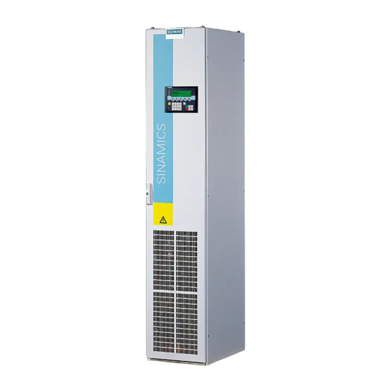
Converter Chassis Units SINAMICS G130 █ General information The SINAMICS G130 Chassis are AC/AC converters for medium to high-output single drives that can be combined very flexibly with the associated system components and integrated into customer-specific cabinets or directly into machines. - Page 168 Advanced Operator Panel DC link components Braking Modules with braking resistors Motor-side power components Motor reactors dv/dt filter plus VPL Motors Asynchronous motors System components for SINAMICS G130 chassis units SINAMICS Engineering Manual – May 2008 168/396 © Siemens AG...
- Page 169 SINAMICS G130 Engineering Information Configuring sequence for a drive system with SINAMICS G130 chassis units Flowchart for selecting the components of a drive system with SINAMICS G130 chassis units SINAMICS Engineering Manual - May 2008 169/396 © Siemens AG...
-
Page 170: Rated Data Of Converters For Drives With Low Demands On Control Performance
Rated data of converters for drives with low demands on control performance Main applications SINAMICS G130 Chassis are primarily intended for applications which require a lower standard of dynamic response and control accuracy and are usually operated in sensorless vector control mode. - Page 171 Immediate shutdown can also be parameterized. Maximum output frequencies With SINAMICS G130 chassis units, the maximum output frequency is limited to 160 Hz resp. 100 Hz due to the pre- set pulse frequency of f = 2.00 kHz resp. f = 1.25 kHz.
- Page 172 Current derating as a function of installation altitude/ambient temperature If the SINAMICS G130 converters are operated at an installation altitude of >2000 m above sea level, the maximum permissible output current can be calculated using the following tables. The specified values already include a permitted correction between installation altitude and ambient temperature (incoming air temperature at the inlet to the Power Module).
-
Page 173: Incorporating Different Loads Into The 24 V Supply
Incorporating different loads into the 24 V supply The SINAMICS G130 Chassis consists of the Power Module and a CU320 Control Unit which requires a 24 V supply. In addition to the Control Unit, it may also be necessary to supply a further one or two TM31 Terminal Modules which are installed to expand the number of digital and analog inputs/outputs and/or an AOP30 operator panel. -
Page 174: Factory Settings (Defaults) Of Customer Interface On Sinamics G130
SINAMICS G130 Engineering Information █ Factory settings (defaults) of customer interface on SINAMICS G130 The following factory settings are provided to simplify configuring of the customer interface and commissioning. The interfaces can also be assigned as required at any time. - Page 175 SINAMICS G130 Engineering Information The converter is controlled exclusively via the standard digital inputs/outputs on the Control Unit. Terminal block on CU320 -X122 Factory setting Comment ON/OFF 1 Increase setpoint/fixed setpoint 0 Parameters can be set in the firmware to determine whether...
- Page 176 SINAMICS G130 Engineering Information The converter is controlled via the PROFIBUS interface which is integrated as standard. The digital inputs and outputs on the Control Unit as well as the optional customer interface TM31 are used to incorporate external alarm and/or error messages and control signals.
- Page 177 SINAMICS G130 Engineering Information Terminal block on TM31 Factory setting Comment -X541 Bidirectional inputs/outputs DI/DO8 Message: Ready to start DI/DO9 Not assigned Factory-set as input DI/DO10 Not assigned Factory-set as input DI/DO11 External alarm Factory-set as input -X542 Relay outputs (changeover contact)
- Page 178 SINAMICS G130 Engineering Information The converter is controlled exclusively via the digital inputs/outputs or analog inputs/outputs on the optional TM31 customer interface. Terminal block on CU320 -X122 Factory setting Comment Not assigned Not assigned Not assigned Not assigned DI/DO8 Not assigned...
- Page 179 SINAMICS G130 Engineering Information Terminal block on TM31 Factory setting Comment DI/DO10 Not assigned Factory-set as input DI/DO11 External alarm Factory-set as input -X542 Relay outputs (changeover contact) DO 0 Inverter enable (Run) DO 1 Checkback signal No converter fault...
-
Page 180: Line-Side Components
Line reactors can be dispensed with only if the supply cable inductance is sufficiently high or the relative short-circuit power RSC correspondingly low. The following values apply to SINAMICS G130 Chassis: Converter output Line reactor can be Line reactor is... -
Page 181: Line Filters
100% effective without a line reactor. Line filters SINAMICS G130 Chassis are equipped as standard with an integrated line filter for limiting radio frequency interference emissions in accordance with EMC product standard EN 61800-3, category C3 (applications in industrial areas or in the "second"... -
Page 182: Components At The Dc Link
100 kW) or 50 kW (P power 200 kW) are available for SINAMICS G130 chassis units. Higher braking powers can be obtained for larger converters by connecting braking units in parallel (on request). If the braking units are used at ambient temperatures > 40°C and installation altitudes > 2000 m, the derating factors for current and output power listed for the Power Units also apply here. - Page 183 SINAMICS G130 Engineering Information Continuous braking power Power permitted for 15 s in 90 s cycles Power permitted for 20 s in 90 s cycles Power permitted for 40 s in 90 s cycles Load duty cycle diagram and power definitions...
- Page 184 SINAMICS G130 Engineering Information Example: In the following example, we will calculate the rating of the Braking Module and braking resistor for a 450 kW Power Module. Mean braking power The mean braking power is calculated as follows: Mean braking power = 150 kW x 20 s / 90 s = 33.3...
-
Page 185: Load-Side Components And Cables
110 kW - 560 kW 300 m 450 m 660 V – 690 V 3AC 75 kW - 800 kW 300 m 450 m Permissible motor cable lengths for SINAMICS G130 SINAMICS Engineering Manual - May 2008 185/396 © Siemens AG... - Page 186 300 m 450 m Permissible motor cable lengths for SINAMICS G130 (continued) Under certain conditions, the permissible cable lengths can be increased even further through the series connection of two motor reactors. Cable lengths for two motor reactors in series and the corresponding limitations are available on request.
-
Page 187: Converter Cabinet Units Sinamics G150
Where the application requires a higher standard of control, i.e. where the control accuracy is more important than the dynamic response, SINAMICS G150 cabinets can be equipped with an SMC30 speed encoder interface which enables them to operate with TTL/HTL incremental encoders (option K50). SINAMICS Engineering Manual - May 2008 187/396 © Siemens AG... - Page 188 As the switching losses in the motor-side IGBT inverter increase in proportion to the pulse frequency, the output current must be reduced accordingly. SINAMICS Engineering Manual – May 2008 188/396 © Siemens AG...
- Page 189 1500 A G150 parallel converter / the specified currents represent the total current of the two parallel-connected converter units SINAMICS G150: Permissible output current as a function of pulse frequency SINAMICS Engineering Manual - May 2008 189/396 © Siemens AG...
- Page 190 91 % ... 4000 96 % 92 % 87 % 83 % 80 % 76 % 95 % 91 % 87 % Voltage derating as a function of installation altitude SINAMICS Engineering Manual – May 2008 190/396 © Siemens AG...
-
Page 191: Factory Settings (Defaults) Of Customer Interface On Sinamics G150
Input for KTY84 temperature sensor or PTC thermistor -Temp The factory settings of the bidirectional inputs/outputs are underscored. A jumper must be inserted here if these inputs are not used SINAMICS Engineering Manual - May 2008 191/396 © Siemens AG... - Page 192 SINAMICS G150 Engineering Information Customer terminal block Customer terminal block on the TM31 Terminal Module SINAMICS Engineering Manual – May 2008 192/396 © Siemens AG...
-
Page 193: Cable Cross-Sections And Connections On Sinamics G150 Cabinet Units
4x240 4x500 1GH35-8AA0 860 2x240 4x240 4x500 2x185 4x240 4x500 1GH37-4AA0 1320 3x185 8x240 8x500 3x150 6x240 6x500 (18) Busbar 1GH38-1AA0 1360 4x150 8x240 8x500 3x185 6x240 6x500 (18) Busbar SINAMICS Engineering Manual - May 2008 193/396 © Siemens AG... - Page 194 3x185 6x240 6x500 (18) Busbar The recommendations for the North American market in AWG or MCM must be taken from the appropriate NEC (National Electrical Code)/CEC (Canadian Electrical Code) standards. SINAMICS Engineering Manual – May 2008 194/396 © Siemens AG...
-
Page 195: Required Cable Cross-Sections For Line And Motor Connections
DIN VDE 0298 Part 2 / DIN VDE 0276-1000. With an ambient temperature of 40 °C, the cross-sections of copper cables can be based on the following table. SINAMICS Engineering Manual - May 2008 195/396 © Siemens AG... -
Page 196: Grounding And Pe Conductor Cross-Section
• Through their controllers, the converters limit the load current (motor and ground fault currents) to an rms value corresponding to the rated current. We therefore recommend the use of a PE conductor cross-section analogous to the phase conductor cross-section for grounding the converter cabinet. SINAMICS Engineering Manual – May 2008 196/396 © Siemens AG... -
Page 197: Line-Side Components
Ratio of the short-circuit power S at the PCC to the fundamental frequency apparent power S of the connected k Line Converter converters (according to EN 50 178 / VDE 0160). SINAMICS Engineering Manual - May 2008 197/396 © Siemens AG... -
Page 198: Line Filters
The efficiency of the filters as regards grounding and shielding can be guaranteed only if the drive is properly installed. For further details, please refer to the section "Line filters" of the chapter "Fundamental Principles and System Description". SINAMICS Engineering Manual – May 2008 198/396 © Siemens AG... -
Page 199: Components At The Dc Link
Apart from the average braking power, the required peak braking power must also be taken into account when braking units are selected (Braking Module and braking resistors). The tables and diagrams below illustrate the correlations. SINAMICS Engineering Manual - May 2008 199/396 © Siemens AG... - Page 200 380 V – 480 V 3AC 774 V 673 V 500 V – 600 V 3AC 967 V 841 V 660 V – 690 V 3AC 1158 V 1070 V Response thresholds of braking units SINAMICS Engineering Manual – May 2008 200/396 © Siemens AG...
- Page 201 The peak power requirement is the determining factor in choosing the correct rating of Braking Module and braking resistor, i.e., a braking unit of ≥ 95.4 kW must be provided. The braking unit with 25 kW (P = 100 kW) must be selected. SINAMICS Engineering Manual - May 2008 201/396 © Siemens AG...
-
Page 202: Load-Side Components And Cables
110 kW - 1000 kW 300 m 450 m 660 V – 690 V 3AC 75 kW - 1500 kW 300 m 450 m Permissible motor cable lengths for SINAMICS G150 SINAMICS Engineering Manual – May 2008 202/396 © Siemens AG... -
Page 203: Sinamics G150 Parallel Converters (Sinamics G150 Power Extension)
Customer terminal block Operator panel (-A60) Supply connection Motor connection Supply connection Motor connection (-X1) (-X2) (-X1) (-X2) Main switch (-Q1) Main switch (-Q1) SINAMICS G150 parallel converter SINAMICS Engineering Manual - May 2008 203/396 © Siemens AG... - Page 204 The following information describes the possible line-side and motor-side configurations of SINAMICS G150 parallel converters and the associated supplementary conditions that have to be taken in account. SINAMICS Engineering Manual – May 2008 204/396 © Siemens AG...
-
Page 205: 6-Pulse Operation Of Sinamics G150 Parallel Converters
The motor-side limitations and restrictions with respect to the operation of motors with electrically isolated winding systems are described on the following pages in the section “Operation of G150 parallel converters at motors with two electrically isolated winding systems”. SINAMICS Engineering Manual - May 2008 205/396 © Siemens AG... - Page 206 (cables of identical type with the same cross-section and length) The motor-side limitations and restrictions are described on the following pages in the section “Operation at motors with two electrically isolated winding systems and one common winding system”. SINAMICS Engineering Manual – May 2008 206/396 © Siemens AG...
-
Page 207: 12-Pulse Operation Of Sinamics G150 Parallel Converters
12-pulse operation must be equipped with Option L87 / insulation monitor. The motor-side limitations and restrictions are described on the following pages in the section “Operation at motors with two electrically isolated winding systems and one common winding system”. SINAMICS Engineering Manual - May 2008 207/396 © Siemens AG... -
Page 208: Operation At Motors With Electrically Isolated Winding Systems And One Common Winding System
7.5 % lower than the currents of the individual converters. Allowance is already made for this reduction factor in the current values in catalog D11 and in the table on the previous pages. SINAMICS Engineering Manual – May 2008 208/396 © Siemens AG... -
Page 209: Special Features To Note When Precharging Sinamics G150 Parallel Converters
660 V to 690 V 3AC 1000 6SL3710–2GH41–1AA0 L13 / main contactor 1350 6SL3710–2GH41–4AA0 L13 / main contactor 1500 6SL3710–2GH41–5AA0 L26 / circuit breaker Required options for ensuring correct precharging SINAMICS Engineering Manual - May 2008 209/396 © Siemens AG... -
Page 210: Brief Overview Of Sinamics G150 Parallel Converters With Production Date Up To Autumn 2007
97 % the line voltage: 97 % the line voltage: 92 % Short overview about the configurations of SINAMICS G150 parallel converters with production date up to autumn 2007 SINAMICS Engineering Manual – May 2008 210/396 © Siemens AG... -
Page 211: Brief Overview Of Sinamics G150 Parallel Converters With Production Date From Autumn 2007
97 % 92 % 97 % 92 % Short overview about the configurations of SINAMICS G150 parallel converters with production date from autumn 2007 SINAMICS Engineering Manual - May 2008 211/396 © Siemens AG... -
Page 212: Sinamics S120, General Information About Built-In And Cabinet Units
Dynamic response Very high High Control modes with encoder Position control/ Position control/ None Speed control/ Speed control/ Torque control Torque control SINAMICS Engineering Manual – May 2008 212/396 © Siemens AG... - Page 213 These values refer to with synchronous motors 4 times with VPM, synchronous motors of see catalog PM21 type 1FK7/1FT6. Please note the limit voltage (kE factor) for motors from external suppliers. SINAMICS Engineering Manual - May 2008 213/396 © Siemens AG...
-
Page 214: Control Properties, Definitions
±M . Approx. additional inaccuracy of ± 2.5% in rated field-weakening range. Servo: Speed operating range 1:10 referred to rated speed. Vector: Speed operating range 1:50 referred to rated speed. SINAMICS Engineering Manual – May 2008 214/396 © Siemens AG... - Page 215 . Approx. additional inaccuracy of ± 2.5 % in rated field-weakening range. Servo: Speed operating range 1:10 referred to rated speed. Vector: Speed operating range 1:50 referred to rated speed. SINAMICS Engineering Manual - May 2008 215/396 © Siemens AG...
- Page 216 30 rpm 1% of n < 100 kW rated e.g. motor with 1500 rpm: 15 rpm 0.5% of n > 500 kW rated e.g. motor with 1500 rpm: 7.5 rpm SINAMICS Engineering Manual – May 2008 216/396 © Siemens AG...
-
Page 217: Rating Data
Maximum attainable output frequency frequency 1.25 kHz 100 Hz 2.00 kHz 160 Hz 2.50 kHz 200 Hz ≥ 4.00 kHz 300 Hz Maximum attainable output frequency as a function of pulse frequency SINAMICS Engineering Manual - May 2008 217/396 © Siemens AG... -
Page 218: Drive Cliq
Only cables adapted to the given ambient conditions must be used. Information can be found in the SINAMICS catalogs. SINAMICS Engineering Manual – May 2008 218/396 © Siemens AG... - Page 219 DRIVE-CLiQ cables supplied with the chassis units For units in Booksize format the DRIVE-CliQ cables are supplied in the relevant width to make the connection to the next following module. SINAMICS Engineering Manual - May 2008 219/396 © Siemens AG...
-
Page 220: Cable Installation
Line Module. The connections between adjacent Motor Modules are made with the 0.6 m DRIVE-CLiQ-cables [2] which are included in the accessories pack of each Motor Module in frame size FX. SINAMICS Engineering Manual – May 2008 220/396 © Siemens AG... - Page 221 0.95 m DRIVE-CLiQ cable can also be used to link Motor Modules of different frame sizes, i.e. FX and GX (please note the difference in depth of 200 mm between frame sizes FX and GX). This cable is shown as cable [2] in the picture below. SINAMICS Engineering Manual - May 2008 221/396 © Siemens AG...
- Page 222 Line Module. The DRIVE-CLiQ cables from the Control Unit to the Line Module and the first Motor Module must be routed through the rubber sleeve on the left-hand side panel of the unit. SINAMICS Engineering Manual – May 2008 222/396 © Siemens AG...
-
Page 223: Specification Of The Required Control Performance And Selection Of The Control Unit
V/f control 250 µs Plus one Infeed (BLM, SLM, ALM). No. of axes applies only to basic scope of functions. 400 µs Extended setpoint channel is a standard feature. 500 µs SINAMICS Engineering Manual - May 2008 223/396 © Siemens AG... - Page 224 3x vector control 1.25 4x vector control 1.25 1x V/f control 1.25 2x V/f control 1.25 3x V/f control 1.25 4x V/f control 1.25 5x V/f control 1.25 6x V/f control 1.25 SINAMICS Engineering Manual – May 2008 224/396 © Siemens AG...
-
Page 225: Specification Of Component Cabling
Wiring of DRIVE-CLiQ connections illustrated by example of units in Booksize format Wiring of DRIVE-CLiQ connections illustrated by example of units in chassis format with different current controller clock cycles SINAMICS Engineering Manual - May 2008 225/396 © Siemens AG... - Page 226 DRIVE-CLiQ connection must be planned accordingly. Drive group comprising up to 4 Motor Modules in chassis format with the same current controller clock cycle (400 µs) SINAMICS Engineering Manual – May 2008 226/396 © Siemens AG...
- Page 227 For further information, please refer to the subsection "DRIVE-CLiQ wiring" of the chapter "Modular Cabinet Unit System S120 Cabinet Modules" and to the section which deals specifically with "Booksize Base Cabinet/ Booksize Cabinet Kits“. SINAMICS Engineering Manual - May 2008 227/396 © Siemens AG...
-
Page 228: Check Of The Maximum Dc Link Capacitance
Infeed Modules connected in parallel multiplied by their maximum DC link capacitance. Prerequisite for this is that all units connected in parallel are connected to the supply voltage simultaneously (e.g. by a circuit breaker). SINAMICS Engineering Manual – May 2008 228/396 © Siemens AG... -
Page 229: Capacitance Values
The order number 6SL3x30 stands for 6SL3330 of the S120 Chassis units and also for 6SL3730 of the S120 Cabinet Modules. These modules are exclusively to the S120 Cabinet Modules range. SINAMICS Engineering Manual - May 2008 229/396 © Siemens AG... - Page 230 This units are not available to the S120 Cabinet Modules range. The order number 6SL3x30 stands for 6SL3330 of the S120 Chassis units and also for 6SL3730 of the S120 Cabinet Modules. SINAMICS Engineering Manual – May 2008 230/396 © Siemens AG...
- Page 231 The order number 6SL3x30 stands for 6SL3330 of the S120 Chassis units and also for 6SL3730 of the S120 Cabinet Modules. The precharging is limited by the precharging circuit in the corresponding Active Interface Module. SINAMICS Engineering Manual - May 2008 231/396 © Siemens AG...
- Page 232 S120 Booksize units with internal and external air cooling The order number 6SL3x20 stands for 6SL3320 of the S120 Chassis units and also for 6SL3720 of the S120 Cabinet Modules. SINAMICS Engineering Manual – May 2008 232/396 © Siemens AG...
-
Page 233: Braking Module / External Braking Resistor
Braking Module. The values for the response thresholds of the Braking Modules and the corresponding DC link voltages during braking operation are given the following table. SINAMICS Engineering Manual - May 2008 233/396 © Siemens AG... - Page 234 Power, which is permissable for 15 s every 90 s Power, which is permissable for 20 s every 90 s Power, which is permissable for 40 s every 90 s Load diagram for Braking Module and braking resistor SINAMICS Engineering Manual – May 2008 234/396 © Siemens AG...
-
Page 235: Braking Resistors For Power Units In Chassis Format
The connection cables to the Braking Module must not exceed 100 m. A short circuit-proof and ground fault-proof cable routing must also be provided. SINAMICS Engineering Manual - May 2008 235/396 © Siemens AG... - Page 236 Fits to the Braking 6SL3300- 6SL3300- 6SL3300- 6SL3300- 6SL3300- 6SL3300- Module with order 1AE31- 1AE32- 1AF31- 1AF32- 1AH31- 1AH32- number 3AA0 5 . A0 3AA0 5 . A0 3AA0 5 . A0 SINAMICS Engineering Manual – May 2008 236/396 © Siemens AG...
-
Page 237: Maximum Connectable Motor Cable Lengths
To provide a sufficient safety margin between this resonant frequency and the pulse frequency, the maximum possible motor cable length is limited, even when several motor reactors are connected in series. SINAMICS Engineering Manual - May 2008 237/396 © Siemens AG... -
Page 238: Chassis Units
You must, therefore, refer to the technical specifications for the relevant Motor Modules. For more information, see section “Motor reactors” of the chapter “Fundamental Principles and System Description”. SINAMICS Engineering Manual – May 2008 238/396 © Siemens AG... -
Page 239: Checking The Total Cable Length For Multi-Motor Drives
Smart Line Module HX+JX 710 to 1400 to 1430 2750 Active Line Module HX+JX 560 to 1400 to 1270 2250 Permissible total cable length for SINAMICS S120 Infeed Modules feeding multi-motor drives SINAMICS Engineering Manual - May 2008 239/396 © Siemens AG... -
Page 240: Modular Cabinet Unit System Sinamics S120 Cabinet Modules
Alternatively selection of order-specific integration engineering (please see catalog) Sequencing of the components of the drive configuration Separation of the drive configuration into individual transportation units SINAMICS Engineering Manual – May 2008 240/396 © Siemens AG... -
Page 241: Dimensioning And Selection Information
Voltage derating as a function of installation altitude The units with supply voltages of 660 V to 690 V 3AC (Order number 6SL3720-1THxx-xAA0) cannot be used at installation altitudes > 3500m. SINAMICS Engineering Manual - May 2008 241/396 © Siemens AG... - Page 242 Voltage derating as a function of installation altitude Additional derating values (e.g. with increased pulse frequency) can be found in the chapter “SINAMICS S120, General Information about Built-in and Cabinet Units”. SINAMICS Engineering Manual – May 2008 242/396 © Siemens AG...
-
Page 243: Degrees Of Protection Of S120 Cabinet Modules
For optimum cost-effectiveness, different combinations of busbar sizes can be selected. When selecting busbars, it is important to remember that systems of adjacent Cabinet Modules must be mutually compatible (see table below and options selection matrix of the relevant Cabinet Modules in the catalog). SINAMICS Engineering Manual - May 2008 243/396 © Siemens AG... -
Page 244: Required Cable Cross-Sections For Line And Motor Connections
With an ambient temperature of 40 °C, the cross- sections of copper cables can be based on the following table. Current carrying capacity of cables acc. to DIN VDE 0298 part 2 at 40°C SINAMICS Engineering Manual – May 2008 244/396 © Siemens AG... -
Page 245: Cooling Air Requirements
Supply voltage 500 V to 690 V 3AC 0.36 0.36 0.36 0.78 0.78 1000 1.08 1.08 1400 1.08 1.08 Components use natural convection Fan for degree of protection IP23, IP43, IP54 (in combination with Basic Line Modules) SINAMICS Engineering Manual - May 2008 245/396 © Siemens AG... - Page 246 Cooling air requirement Frame size [kW] [m³/s] rated Supply voltage 380 V to 480 V Supply voltage 500 V to 600 V Supply voltage 660 V to 690 V 400mm 500-1200 0.14 SINAMICS Engineering Manual – May 2008 246/396 © Siemens AG...
-
Page 247: Auxiliary Power Requirements
Cabinet Modules require an auxiliary energy supply to function properly. This power requirement must be included in the configuration and supplied from an external source. Please ask your Siemens contact for a solution. Line Connection Modules The auxiliary voltage for the Line Connection Modules is connected directly to input terminals. The following... - Page 248 Supply voltage 500 V – 690 V 3AC (DC link voltage 675 V – 930 V) 6SL3730-1TH33-0AA0 6SL3730-1TH34-3AA0 6SL3730-1TH36-8AA0 6SL3730-1TH41-1AA0 6SL3730-1TH41-1BA0 6SL3730-1TH41-1BC0 6SL3730-1TH41-4AA0 1100 1180 6SL3730-1TH41-4BA0 1100 1180 6SL3730-1TH41-4BC0 1100 1180 6SL3730-1TH41-8AA0 1500 1580 6SL3730-1TH41-8BA0 1500 1580 6SL3730-1TH41-8BC0 1500 1580 Power requirement of control electronics SINAMICS Engineering Manual – May 2008 248/396 © Siemens AG...
- Page 249 6SL3730-6TG38-8BA0 6SL3730-6TG38-8BC0 6SL3730-6TG41-2AA0 1000 1009 6SL3730-6TG41-2BA0 1000 1009 6SL3730-6TG41-2BC0 1000 1009 6SL3730-6TG41-7AA0 1400 1430 6SL3730-6TG41-7BA0 1400 1430 6SL3730-6TG41-7BC0 1400 1430 Power requirement of Control electronics, auxiliary power supply for fans. SINAMICS Engineering Manual - May 2008 249/396 © Siemens AG...
- Page 250 6SL3730-7TG41-0BA0 JX+JI 1100 1025 1.87 6SL3730-7TG41-0BC0 JX+JI 1100 1025 1.87 6SL3730-7TG41-3BA0 JX+JI 1400 1270 1.87 6SL3730-7TG41-3BC0 JX+JI 1400 1270 1.87 Power requirement of Control electronics, auxiliary power supply for fans. SINAMICS Engineering Manual – May 2008 250/396 © Siemens AG...
- Page 251 Supply voltage 500 V – 690 V 3AC (DC link voltage 650 V – 1035 V) 6SL3720-1TG28-5AA0 6SL3720-1TG31-0AA0 6SL3720-1TG31-2AA0 6SL3720-1TG31-5AA0 6SL3720-1TG31-8AA0 6SL3720-1TG32-2AA0 6SL3720-1TG32-6AA0 6SL3720-1TG33-3AA0 6SL3720-1TG34-1AA0 6SL3720-1TG34-7AA0 6SL3720-1TG35-8AA0 6SL3720-1TG37-4AA0 1.25 6SL3720-1TG38-1AA0 1.25 6SL3720-1TG38-8AA0 6SL3720-1TG41-0AA0 1000 6SL3720-1TG41-3AA0 1200 SINAMICS Engineering Manual - May 2008 251/396 © Siemens AG...
- Page 252 In preparation 6SL3700-1AH41-2AA1 1200 Auxiliary Power Supply Modules Auxiliary Power Supply Modules do not require an auxiliary voltage supply. No auxiliary power needs to be configured for this type of cabinet. SINAMICS Engineering Manual – May 2008 252/396 © Siemens AG...
- Page 253 AOP30 Advanced Operator Panel Voltage 24 V DC (20.4 V – 28.8 V) Max. power requirement (at 24 V DC) Without backlit display 100 mA With maximum backlit display 200 mA SINAMICS Engineering Manual - May 2008 253/396 © Siemens AG...
-
Page 254: Line Reactors
Ratio of the short-circuit power S at the PCC to the fundamental frequency apparent power S of the connected k line Converter converters (according to EN 50 178 / VDE 0160). SINAMICS Engineering Manual – May 2008 254/396 © Siemens AG... -
Page 255: Parallel Configuration
Power units connected in parallel are controlled by a common Control Unit via DRIVE-CLiQ. The separate ordering of DRIVE-CLiQ cables which establish the connections between the paralleled cabinet units must be considered (please see section “DRIVE-CLiQ wiring”). SINAMICS Engineering Manual - May 2008 255/396 © Siemens AG... -
Page 256: Weights Of S120 Cabinet Modules
Supply voltage 500 V to 690 V 3AC 1000 1400 Unit prepared for parallel connection on a Line Connection Module on right Unit prepared for parallel connection on a Line Connection Module on left SINAMICS Engineering Manual – May 2008 256/396 © Siemens AG... - Page 257 Supply voltage 380 V to 480 V 3AC 100mm 20.1 200mm 23.3 100mm 20.1 200mm 23.3 100mm 200mm 23.3 100mm 200mm 2*18 24.8 100mm 21.9 200mm 200mm 200mm 300mm 300mm SINAMICS Engineering Manual - May 2008 257/396 © Siemens AG...
- Page 258 The weight specified on the check sheet enclosed with the delivery might deviate slightly from the standard weights specified above. Suitable hoisting gear operated by trained personnel is also required due to the weight of the cabinets. SINAMICS Engineering Manual – May 2008 258/396 © Siemens AG...
-
Page 259: Information About Equipment Handling
Auxiliary voltage output (+24 V) Safety function (“Safe Torque Off/ Safe Stop1“) Connection is provided on the separate customer terminal block –X55 with Booksize Cabinet Kits Not on Line Modules SINAMICS Engineering Manual - May 2008 259/396 © Siemens AG... - Page 260 X4. When option K82 is not installed, voltage supply links are connected so that a pulse disable is not triggered because option K82 is missing. It is of course still possible to connect an external interface. SINAMICS Engineering Manual – May 2008 260/396 © Siemens AG...
-
Page 261: Customer Terminal Block -X55
–A55“). Terminal –X10 on the module is also assigned which means that a 24 V supply can be picked off via a connector for servicing purposes. The maximum current rating is 250 mA. SINAMICS Engineering Manual - May 2008 261/396 © Siemens AG... -
Page 262: Auxiliary Voltage Distribution
It is, of course, always possible to connect a terminal to the auxiliary voltage busbar. SINAMICS Engineering Manual – May 2008 262/396 © Siemens AG... -
Page 263: Drive-Cliq Wiring
Cabinet Module. This can involve a connection to the Control Unit or require a connection to the power unit as defined by the rules for DRIVE- SINAMICS Engineering Manual - May 2008 263/396 © Siemens AG... -
Page 264: Erection Of Cabinets
Inter-cabinet DRIVE-CLiQ connecting cables can also be fitted in the factory on request. The order-specific Integration Engineering (order number 6SL3780-0Ax00-0AA0) can, for example, be used for this purpose. For further details, please ask your Siemens contact. Erection of cabinets The standard erection sequence for Cabinet Modules is from the left, starting with the Line Connection Modules, followed by the Line Modules and ending with the Motor Modules on the far right. -
Page 265: Door Opening Angle
Maximum door opening angle: with degree of protection IP20/IP21 without options in the cabinet door 135 ° with degree of protection IP23/IP43/IP54 110 ° with option L37 (DC-Switch) 110 ° SINAMICS Engineering Manual - May 2008 265/396 © Siemens AG... -
Page 266: Line Connection Modules
JL, KL and LL are equipped with a fan to provide extra internal cooling. On these models, the fan is mounted in the hood, protected by fuses and connected separately to a clamp in the terminal area. SINAMICS Engineering Manual – May 2008 266/396 © Siemens AG... -
Page 267: Planning Recommendations, Special Features
- 7,5 % for Smart Line Modules - 5 % for Active Line Modules The listed current values are based on an ambient temperature (inlet air temperature) of 40 °C SINAMICS Engineering Manual - May 2008 267/396 © Siemens AG... -
Page 268: Parallel Connections
When Cabinet Modules are selected and combined as defined in the above assignment table, the Line Connection Modules are equipped and prepared as specified in the factory. For other combinations of Cabinet Modules which deviate from the standard, please ask your Siemens contact for further information. -
Page 269: Dc Busbar
Circuit breakers Line Connection Modules for current ratings up to 800 A are equipped as standard with a manually operated fuse switch-disconnector. SIEMENS circuit breakers from the SENTRON WL product range are installed for higher input currents. The circuit breaker is controlled and supplied internally. It is not necessary to install additional cabinet wiring or provide separate control cables. - Page 270 For Cabinet Modules with degree of protection IP54, shrouding covers are installed as standard in front of the circuit breaker to meet the stringent requirements of this degree of protection. SINAMICS Engineering Manual – May 2008 270/396 © Siemens AG...
-
Page 271: Short-Circuit Strength
(preset), max. = 50 kA rated Short-circuit strength The Line Connection Modules are mechanically designed to withstand the tolerance limits of the circuit breaker. Higher short-circuit strengths are available on request. SINAMICS Engineering Manual - May 2008 271/396 © Siemens AG... -
Page 272: Basic Line Modules
On these units, the DC link is precharged via a separate, line-side precharging circuit. This is fitted in the Line Connection Module and selected via option L43 of the LCM. SINAMICS Engineering Manual – May 2008 272/396 © Siemens AG... -
Page 273: Dc Link Fuses
Please note that only Basic Line Modules with exactly the same output power rating can be connected in parallel. The potential for imbalances in current distribution means that current derating of 7.5 % must be applied and this must be taken into account when the modules are dimensioned. SINAMICS Engineering Manual - May 2008 273/396 © Siemens AG... -
Page 274: Smart Line Modules
4 times and 7.8 times higher than the DC link capacitance included in the Smart Line Module itself. Please refer to the section “Checking the maximum DC link capacitance” of the chapter “SINAMICS S120, General Information about Built-in and Cabinet Units”. SINAMICS Engineering Manual – May 2008 274/396 © Siemens AG... -
Page 275: Dc Link Fuses
Information on parallel configurations in the chapter “Fundamental Principles and System Description” and also on the use of DRIVE-CLiQ cables and how to install them in the sections “Information about equipment handling” and “DRIVE-CLiQ wiring” must be noted. SINAMICS Engineering Manual - May 2008 275/396 © Siemens AG... -
Page 276: Active Line Modules + Active Interface Modules
DRIVE-CLiQ connection to the power unit is already included. The terminal block and the Control Unit CU320, which is available as an option, are installed in the Active Line Module. SINAMICS Engineering Manual – May 2008 276/396 © Siemens AG... - Page 277 The connections of the precharging circuit, as well as control cables from the Active Line Module to the circuit breaker are already included in the S120 Cabinet Modules and harmonized via option L42 with the corresponding LCM. SINAMICS Engineering Manual - May 2008 277/396 © Siemens AG...
-
Page 278: Dc Link Fuses
Example configuration of Active Line Modules + Active Interface Modules in frame sizes JX+JI for parallel connection for mounting on the left side as well as for mounting on the right side of a LCM SINAMICS Engineering Manual – May 2008 278/396 © Siemens AG... - Page 279 Information on parallel configurations in the chapter “Fundamental Principles and System Description” and also on the use of DRIVE-CLiQ cables and how to install them in the sections “Information about equipment handling” and “DRIVE-CLiQ wiring” must be noted. SINAMICS Engineering Manual - May 2008 279/396 © Siemens AG...
-
Page 280: Motor Modules
Frame sizes FX and GX are also fitted with a special terminal area for connection of motor cables. With the frame sizes HX and JX the cables are connected directly to the Power Unit. SINAMICS Engineering Manual – May 2008 280/396 © Siemens AG... -
Page 281: Dc Link Fuses
These data relate to units with supply voltages of 500 V to 690 V 3AC (MLFB 6SL3720- 1TGxx-xAA0) and 660 V to 690 V 3AC (MLFB 6SL3720-1 THxx-xAA0). SINAMICS Engineering Manual - May 2008 281/396 © Siemens AG... - Page 282 Please note the supplementary conditions applicable to parallel connections, such as the control of motors with only one common winding system. These are described in the section "Parallel connections of converters" of the chapter "Fundamental Principles and System Description". SINAMICS Engineering Manual – May 2008 282/396 © Siemens AG...
-
Page 283: Booksize Base Cabinet / Booksize Cabinet Kits
For information about output reactors, please refer to section "Options / Option L08/ L09". Example of a Booksize Cabinet Kit 200 mm SINAMICS Engineering Manual - May 2008 283/396 © Siemens AG... -
Page 284: Dc Link Fuses
–A55 in combination with a Control Unit (option K90/ K91). For further information, please refer to the sections on these specific components in this chapter. SINAMICS Engineering Manual – May 2008 284/396 © Siemens AG... - Page 285 The power unit of the third Cabinet Kit requires a cable of at least 200 mm (width of adjacent Cabinet Kit + 100 mm (bending radius) = 300 mm. The following is selected: 6SL3060-4AM00-0AA0 with a length of 360 mm. Be aware that the cables must be properly secured. SINAMICS Engineering Manual - May 2008 285/396 © Siemens AG...
- Page 286 Cabinet Kits in the 1200 mm wide Base Cabinet (applies to 100 mm wide Cabinet Kits in each case). The Base Cabinets feature defined slots which are equipped in the factory according to the order data. The ordered kits are not SINAMICS Engineering Manual – May 2008 286/396 © Siemens AG...
- Page 287 If you wish the Booksize devices to be installed in the Base Cabinets in a particular order, please notify your Siemens contact. Booksize Base Cabinets are designed to function without a cabinet fan. When a protection class higher than IP21 is selected, thermostat-controlled fans to support efficient air circulation are fitted.
-
Page 288: Central Braking Modules
In most applications, the Central Braking Modules are only used for occasional braking operation, but it is possible to use them for continuous braking operation. In this case, the load duty cycles shown in the following diagram must be taken into account. SINAMICS Engineering Manual – May 2008 288/396 © Siemens AG... -
Page 289: Position In The Dc Link Configuration
DC link configuration by means of a DC switch (option 37). The disconnection is only allowed for a short time, e.g. for repair or maintainance purposes. If the disconnection is required for a longer time, the Central Braking Module should be deactivated. SINAMICS Engineering Manual - May 2008 289/396 © Siemens AG... -
Page 290: Dc Link Fuses
The braking resistors are dimensioned for occasional regenerative operation. In the case that the braking resistor is not sufficient to meet the demands of special applications, a suitable braking resistor must be designed individually. SINAMICS Engineering Manual – May 2008 290/396 © Siemens AG... - Page 291 When outdoor installation of the braking resistor is required protection against water must be ensured as the degree of protection of IP21 is not sufficient in this case. SINAMICS Engineering Manual - May 2008 291/396 © Siemens AG...
-
Page 292: Options
The Safe Torque Off function prevents unexpected rotation of the connected motor at standstill. Before the Safe Stop1 function decelerates the motor in accordance to the deceleration ramp. These two safety functions are included as standard with S120 Cabinet Modules. SINAMICS Engineering Manual – May 2008 292/396 © Siemens AG... - Page 293 The values are valid for a frequency of 50 Hz. At 60 Hz the cable lengths must be reduced by 20 %. • DC (min. cross-section = 0.75 mm ): 1500 m SINAMICS Engineering Manual - May 2008 293/396 © Siemens AG...
- Page 294 Inside a cabinet module all connections are pre-wired and the cabinet is therefore ready for connection. The SIMATIC S7 shown is not necessary and thus only demonstrates a possible connection variant. SINAMICS Engineering Manual – May 2008 294/396 © Siemens AG...
- Page 295 Please note the additional information on the safety functions Safe Torque Off and Safe Stop 1 in the chapter “General Engineering Information for SINAMICS” in the section “Safety-integrated, drive-integrated safety functions”. SINAMICS Engineering Manual - May 2008 295/396 © Siemens AG...
-
Page 296: Option K90 / 91 (Control Unit Cu320)
The firmware version is encoded as follows in the order number: 6SL3054-0 ■ ■0 ■-1AA0 Order No.: Firmware version 1 Version Without performance expansion With performance expansion 1 Encoding of firmware version in the order number SINAMICS Engineering Manual – May 2008 296/396 © Siemens AG... -
Page 297: Option L08 / L09 (Motor Reactors)
The withdrawable breaker version should be used for applications which require a high level of plant availability or switching frequency. The advantage of the withdrawable version is that the breakers can be replaced quickly. SINAMICS Engineering Manual - May 2008 297/396 © Siemens AG... -
Page 298: Option L34 (Circuit Breaker On The Output Side)
Motor Module trips or the auxiliary supply of option L34 fails or the “OFF” button on the circuit breaker is pressed. When the “OFF” button directly on the circuit breaker is pressed, the Motor Module will also be deactivated by disabling the pulses. SINAMICS Engineering Manual – May 2008 298/396 © Siemens AG... -
Page 299: Option L37 (Dc Coupling)
Cables must not be routed in such a way that they impede the air inlet through the cabinet floor opening. To ensure an adequate air-inlet cross-section, the units are shipped without the standard baseplates. The cooling air requirements specified in the section "Dimensioning and selection information" must also be noted. SINAMICS Engineering Manual - May 2008 299/396 © Siemens AG... -
Page 300: Option Y11 (Factory Assembly Of Cabinet Modules Into Transport Units)
Please refer to the assignment tables in the section “Line Connection Modules“. Example: SINAMICS Engineering Manual – May 2008 300/396 © Siemens AG... - Page 301 In this case, the busbar segments (TE1+2 in the example) must be separately connected to the Auxiliary Power Supply Module. The transport unit is shipped with a crane-hoisting transport rail which means that option M90 is not required. SINAMICS Engineering Manual - May 2008 301/396 © Siemens AG...
-
Page 302: Converter Cabinet Units Sinamics S150
The digital inputs and outputs on the CU320 Control Unit are used for internal purposes on S150 cabinets and are not therefore available for use as a customer interface. The TM31 Terminal Module must always be used for this purpose. SINAMICS Engineering Manual – May 2008 302/396 © Siemens AG... -
Page 303: Rated Data And Continuous Operation Of The Converters
1.1 I for high overload for low overload 60 s 60 s 300 s 300 s Load duty cycle definition for low overload Load duty cycle definition for high overload SINAMICS Engineering Manual - May 2008 303/396 © Siemens AG... - Page 304 95 % 900 kW 910 A 87 % 1000 kW 1025 A 86 % 1200 kW 1270 A 79 % SINAMICS S150: Permissible output current as a function of pulse frequency SINAMICS Engineering Manual – May 2008 304/396 © Siemens AG...
- Page 305 ... 4000 96 % 92 % 87 % 83 % 80 % 76 % 91 % 87 % 80 % 76 % Voltage derating as a function of installation altitude SINAMICS Engineering Manual - May 2008 305/396 © Siemens AG...
-
Page 306: Factory Settings (Defaults) Of Customer Interface On Sinamics S150
Jumpers must be inserted for this circuit example (M: internal ground, M1 or M2: External Parameterizable as current or voltage source Individually parameterizable as digital input/output (factory setting: Assigned as output) SINAMICS Engineering Manual – May 2008 306/396 © Siemens AG... - Page 307 DO 1.NO NO contact Max. switching capacity at 250 VAC: No fault in converter 2000 VA Max. switching capacity at 30 VDC: 240 W Customer terminal block with factory settings SINAMICS Engineering Manual - May 2008 307/396 © Siemens AG...
-
Page 308: Cable Cross-Sections And Connections On Sinamics S150 Cabinets
40 °C. When the conditions differ from the above stated (cable routing, cable grouping, ambient temperature), the planning instructions for routing the cables must be taken into account. SINAMICS Engineering Manual – May 2008 308/396 © Siemens AG... -
Page 309: Required Cable Cross-Sections For Line And Motor Connections
Cross-section of phase Minimum cross-section of the external PE conductor conductor Up to 16 Minimum phase conductor cross-section 16 to 35 35 and above Minimum half the phase conductor cross-section SINAMICS Engineering Manual - May 2008 309/396 © Siemens AG... - Page 310 • Through their controllers, the converters limit the load current (motor and ground fault currents) to an rms value corresponding to the rated current. We therefore recommend the use of a PE conductor cross-section analogous to the phase conductor cross-section for grounding the converter cabinet. SINAMICS Engineering Manual – May 2008 310/396 © Siemens AG...
-
Page 311: Load-Side Components And Cables
110 kW - 800 kW 300 m 450 m 500 V – 690 V 3AC 75 kW - 1200 kW 300 m 450 m Permissible motor cable lengths for SINAMICS S150 SINAMICS Engineering Manual - May 2008 311/396 © Siemens AG... - Page 312 525 m with shielded cables and 787 m with unshielded cables. A second motor reactor is not a standard option and may require an additional cabinet. A second motor reactor is therefore available only on request. SINAMICS Engineering Manual – May 2008 312/396 © Siemens AG...
-
Page 313: Drive Dimensioning
The rated current of the converter or Motor Module must be at least as high as the motor current at full torque in the required load point. When Siemens standard asynchronous motors are used, these can be loaded with the full rated power even in converter-fed operation. They are then utilized according to temperature class F. -
Page 314: Permissible Motor-Converter Combinations
• SINAMICS G130 and G150 are designed for sensorless vector control. With these converters, regenerative energy cannot be returned to the supply system. For this reason, these drives are suitable only for standard applications with low requirements regarding dynamic performance and accuracy. - Page 315 10 ms to the value of the EMF depending on the field-weakening speed of the motor. As a result, the DC link is charged via the freewheeling diodes of the inverter to the amplitude of the EMF of the motor. SINAMICS Engineering Manual - May 2008 315/396 © Siemens AG...
- Page 316 Braking Module. 1. Limitation of the speed in the field-weakening range With SINAMICS G130, G150, S120 (Chassis and Cabinet Modules) and S150 operating in vector control mode, the speed in the field-weakening range is limited to the value n by factory settings, in order to protect the converter.
- Page 317 4th step Option selection Further notes and alternatives Complete the motor Define options for special versions See "Special versions" catalog D86.2 / Chapter 2. Order No. and tests. SINAMICS Engineering Manual - May 2008 317/396 © Siemens AG...
- Page 318 The relevant Infeed must be selected as well. 2 Single Motor Modules Order No. 6SL3320-1TH41-0AA0 SINAMICS S120 Cabinet Modules: The relevant Infeed must be selected as well. 2 Motor Modules Order No. 6SL3720-1TH41-0AA0 SINAMICS Engineering Manual – May 2008 318/396 © Siemens AG...
- Page 319 OFF when the rotor is still revolving. Guide for designing a drive with an HT-direct motor and a SINAMICS converter SINAMICS Engineering Manual - May 2008 319/396 © Siemens AG...
-
Page 320: Motors
1PH7/1PL6 motors with the same rated power are on average 1 to 2 shaft heights smaller than comparable standard asynchronous motors. With converter chassis units SINAMICS G130 and converter cabinet units SINAMICS G150 it is only possible to use the Sensor Module SMC30. Therefore, only TTL/HTL incremental encoders can be used when these motors are operated by SINAMICS G130 and G150. -
Page 321: Special Insulation For Line Supply Voltages > 500 V In Converter-Fed Operation
1500 V 1125 V +10 % Permissible voltage limits for Siemens low-voltage motors with round-wire windings up to 690 V In comparison to standard insulation, the ratio between insulation material and copper within a single slot is less favorable with the special insulation, causing a slight reduction in the rated output of motors with special insulation. -
Page 322: Motor Protection
SINAMCS G150 and S150 cabinets as option L83 (for alarm) and L84 (for shutdown). Operation of explosion proof motors with type of protection "d" Siemens 1MJ asynchronous motors can be connected as explosion-proof motors with flameproof enclosure EEx de IIC both to the mains supply and the converter. -
Page 323: Dimension Drawings
Dimension Drawings Engineering Information Dimension Drawings █ SINAMICS G130 Dimension drawing 1, frame size FX: 380 V to 480 V 110 – 132 kW 660 V to 690 V 75 – 132 kW Front view Side view Required clearance for ventilation - - - - - -... - Page 324 Dimension Drawings Engineering Information SINAMICS G130, continued Dimension drawing 2, frame size GX: 380 V to 480 V 160 – 250 kW 500 V to 600 V 110 – 200 kW 660 V to 690 V 160 – 315 kW...
- Page 325 Dimension Drawings Engineering Information SINAMICS G130, continued Dimension drawing 3, frame size HX: 380 V to 480 V 315 - 450 kW 500 V to 600 V 250 - 400 kW 660 V to 690 V 400 - 560 kW...
- Page 326 Dimension Drawings Engineering Information SINAMICS G130, continued Dimension drawing 4, frame size JX: 380 V to 480 V 560 kW 500 V to 600 V 500 - 560 kW 660 V to 690 V 710 - 800 kW Side view...
-
Page 327: Sinamics Line Harmonics Filter
NEC, CEC (No. of holes) DIN NEC, CEC (No. of holes) (No. of bolts) mm² AWG/MCM AWG/MCM mm² 2 x 240 2 x 500 MCM 2 x 240 2 x 500 SINAMICS Engineering Manual - May 2008 327/396 © Siemens AG... - Page 328 NEC, CEC (No. of NEC, CEC (No. of holes) (No. of bolts) mm² AWG/MCM holes) AWG/MCM mm² 2 x 240 2 x 500 MCM 2 x 240 2 x 500 MCM SINAMICS Engineering Manual – May 2008 328/396 © Siemens AG...
-
Page 329: Sinamics G150 (Type A)
Air inlet area IP23 Option <M23> Cables can enter from below within hatched area IP43 Option <M43> Main circuit breaker, can be secured by padlock (option) IP54 Option <M54> 10. Transport unit SINAMICS Engineering Manual - May 2008 329/396 © Siemens AG... - Page 330 Air inlet area IP23 Option <M23> Cables can enter from below within hatched area IP43 Option <M43> Main circuit breaker, can be secured by padlock (option) IP54 Option <M54> 10. Transport unit SINAMICS Engineering Manual – May 2008 330/396 © Siemens AG...
- Page 331 Air inlet area IP23 Option <M23> Cables can enter from below within hatched area IP43 Option <M43> Main circuit breaker, can be secured by padlock (option) IP54 Option <M54> 10. Transport unit SINAMICS Engineering Manual - May 2008 331/396 © Siemens AG...
- Page 332 Air inlet area IP23 Option <M23> Cables can enter from below within hatched area IP43 Option <M43> Main circuit breaker, can be secured by padlock (option) IP54 Option <M54> 10. Transport unit SINAMICS Engineering Manual – May 2008 332/396 © Siemens AG...
- Page 333 Air inlet area IP23 Option <M23> Cables can enter from below within hatched area IP43 Option <M43> Main circuit breaker, can be secured by padlock (option) IP54 Option <M54> 10. Transport unit SINAMICS Engineering Manual - May 2008 333/396 © Siemens AG...
- Page 334 Air inlet area IP23 Option <M23> Cables can enter from below within hatched area IP43 Option <M43> Main circuit breaker, can be secured by padlock (option) IP54 Option <M54> 10. Transport unit SINAMICS Engineering Manual – May 2008 334/396 © Siemens AG...
- Page 335 Air inlet area IP23 Option <M23> Cables can enter from below within hatched area IP43 Option <M43> Main circuit breaker, can be secured by padlock (option) IP54 Option <M54> 10. Transport unit SINAMICS Engineering Manual - May 2008 335/396 © Siemens AG...
- Page 336 Air inlet area IP23 Option <M23> Cables can enter from below within hatched area IP43 Option <M43> Main circuit breaker, can be secured by padlock (option) IP54 Option <M54> 10. Transport unit SINAMICS Engineering Manual – May 2008 336/396 © Siemens AG...
- Page 337 Air inlet area IP23 Option <M23> Cables can enter from below within hatched area IP43 Option <M43> Main circuit breaker, can be secured by padlock (option) IP54 Option <M54> 10. Transport unit SINAMICS Engineering Manual - May 2008 337/396 © Siemens AG...
- Page 338 Air inlet area IP23 Option <M23> Cables can enter from below within hatched area IP43 Option <M43> Main circuit breaker, can be secured by padlock (option) IP54 Option <M54> 10. Transport unit SINAMICS Engineering Manual – May 2008 338/396 © Siemens AG...
- Page 339 Cables can enter from below within hatched area IP43 Option <M43> Main circuit breaker, can be secured by padlock (option) IP54 Option <M54> 10. 2 transport units, each 1200 mm SINAMICS Engineering Manual - May 2008 339/396 © Siemens AG...
- Page 340 Cables can enter from below within hatched area IP43 Option <M43> Main circuit breaker, can be secured by padlock (option) IP54 Option <M54> 10. 2 transport units, each 1200 mm SINAMICS Engineering Manual – May 2008 340/396 © Siemens AG...
- Page 341 Cables can enter from below within hatched area IP43 Option <M43> Main circuit breaker, can be secured by padlock (option) IP54 Option <M54> 10. 2 transport units, each 1200 mm SINAMICS Engineering Manual - May 2008 341/396 © Siemens AG...
- Page 342 Cables can enter from below within hatched area IP43 Option <M43> Main circuit breaker, can be secured by padlock (option) IP54 Option <M54> 10. 2 transport units, each 1200 mm SINAMICS Engineering Manual – May 2008 342/396 © Siemens AG...
- Page 343 Cables can enter from below within hatched area IP43 Option <M43> Main circuit breaker, can be secured by padlock (option) IP54 Option <M54> 10. 2 transport units, each 1600 mm SINAMICS Engineering Manual - May 2008 343/396 © Siemens AG...
- Page 344 Cables can enter from below within hatched area IP43 Option <M43> Main circuit breaker, can be secured by padlock (option) IP54 Option <M54> 10. 2 transport units, each 1600 mm SINAMICS Engineering Manual – May 2008 344/396 © Siemens AG...
-
Page 345: Sinamics G150 (Type C)
Degree of protection IP20 IP21 Option <M21> Air inlet area IP23 Option <M23> Cables can enter from below within hatched area IP43 Option <M43> IP54 Option <M54> 10. Transport unit SINAMICS Engineering Manual - May 2008 345/396 © Siemens AG... - Page 346 Degree of protection IP20 IP21 Option <M21> Air inlet area IP23 Option <M23> Cables can enter from below within hatched area IP43 Option <M43> IP54 Option <M54> 10. Transport unit SINAMICS Engineering Manual – May 2008 346/396 © Siemens AG...
-
Page 347: Sinamics S120 Chassis (Basic Line Modules)
NEC, CEC (No. of holes) AWG/MCM AWG/MCM AWG/MCM mm² mm² mm² 2 x 185 2 x 350 MCM 2 x 185 2 x 350 2 x 185 2 x 350 MCM SINAMICS Engineering Manual - May 2008 347/396 © Siemens AG... - Page 348 NEC, CEC (No. of holes) AWG/MCM AWG/MCM AWG/MCM mm² mm² mm² 6 x 240 6 x 500 MCM 6 x 240 6 x 500 4 x 240 2 x 500 MCM SINAMICS Engineering Manual – May 2008 348/396 © Siemens AG...
-
Page 349: Sinamics S120 Chassis (Smart Line Modules)
AWG/MCM mm² mm² 2 x 185 2 x 350 MCM 2 x 185 2 x 350 1 x 185 1 x 350 MCM 2 x 185 2 x 350 MCM SINAMICS Engineering Manual - May 2008 349/396 © Siemens AG... - Page 350 AWG/MCM mm² mm² mm² 4 x 240 4 x 500 MCM 60 x 60 x 5 1 x 240 1 x 500 MCM 2 x 240 2 x 500 MCM SINAMICS Engineering Manual – May 2008 350/396 © Siemens AG...
- Page 351 AWG/MCM mm² mm² mm² 6 x 240 6 x 500 MCM 60 x 60 x 8 1 x 240 1 x 500 MCM 2 x 240 2 x 500 MCM SINAMICS Engineering Manual - May 2008 351/396 © Siemens AG...
-
Page 352: Sinamics S120 Chassis (Active Interface Modules)
NEC, CEC (No. of holes) NEC, CEC (No. of holes) AWG/MCM AWG/MCM mm² mm² 2 x 185 2 x 350 MCM 2 x 185 2 x 350 MCM SINAMICS Engineering Manual – May 2008 352/396 © Siemens AG... - Page 353 NEC, CEC (No. of holes) NEC, CEC (No. of holes) AWG/MCM AWG/MCM mm² mm² 2 x 185 2 x 350 MCM 2 x 185 2 x 350 MCM SINAMICS Engineering Manual - May 2008 353/396 © Siemens AG...
- Page 354 NEC, CEC NEC, CEC (No. of holes) AWG/MCM AWG/MCM AWG/MCM mm² mm² mm² 4 x 240 4 x 500 MCM 2 x 16 2 x 240 2 x 500 MCM SINAMICS Engineering Manual – May 2008 354/396 © Siemens AG...
- Page 355 NEC, CEC NEC, CEC (No. of holes) AWG/MCM AWG/MCM AWG/MCM mm² mm² mm² 6 x 240 6 x 500 MCM 2 x 35 4 x 240 4 x 500 MCM SINAMICS Engineering Manual - May 2008 355/396 © Siemens AG...
-
Page 356: Sinamics S120 Chassis (Active Line Modules)
NEC, CEC (No. of holes) AWG/MCM AWG/MCM AWG/MCM mm² mm² mm² 2 x 185 2 x 350 MCM 2 x 185 2 x 350 2 x 185 2 x 350 MCM SINAMICS Engineering Manual – May 2008 356/396 © Siemens AG... - Page 357 NEC, CEC (No. of holes) AWG/MCM AWG/MCM AWG/MCM mm² mm² mm² 2 x 185 2 x 350 MCM 2 x 185 2 x 350 2 x 185 2 x 350 MCM SINAMICS Engineering Manual - May 2008 357/396 © Siemens AG...
- Page 358 AWG/MCM mm² mm² mm² 4 x 240 4 x 500 MCM 60 x 60 x 5 1 x 240 1 x 500 MCM 2 x 240 2 x 500 MCM SINAMICS Engineering Manual – May 2008 358/396 © Siemens AG...
- Page 359 AWG/MCM mm² mm² mm² 6 x 240 6 x 500 MCM 60 x 60 x 8 1 x 240 1 x 500 MCM 2 x 240 2 x 500 MCM SINAMICS Engineering Manual - May 2008 359/396 © Siemens AG...
-
Page 360: Sinamics S120 Chassis (Motor Modules)
NEC, CEC (No. of holes) AWG/MCM AWG/MCM AWG/MCM mm² mm² mm² 2 x 185 2 x 350 MCM 2 x 185 2 x 350 2 x 185 2 x 350 MCM SINAMICS Engineering Manual – May 2008 360/396 © Siemens AG... - Page 361 NEC, CEC (No. of holes) AWG/MCM AWG/MCM AWG/MCM mm² mm² mm² 2 x 185 2 x 350 MCM 2 x 185 2 x 350 2 x 185 2 x 350 MCM SINAMICS Engineering Manual - May 2008 361/396 © Siemens AG...
- Page 362 AWG/MCM AWG/MCM mm² mm² mm² 60 x 60 x 5 4 x 240 4 x 500 1 x 240 1 x 500 MCM 2 x 240 2 x 500 MCM SINAMICS Engineering Manual – May 2008 362/396 © Siemens AG...
- Page 363 AWG/MCM AWG/MCM mm² mm² mm² 60 x 60 x 8 6 x 240 6 x 500 1 x 240 1 x 500 MCM 2 x 240 2 x 500 MCM SINAMICS Engineering Manual - May 2008 363/396 © Siemens AG...
-
Page 364: Sinamics S120 Chassis Liquid Cooled (Power Modules)
NEC, CEC (No. of holes) DIN NEC, CEC (No. of holes) NEC, CEC (No. of holes) AWG/MCM AWG/MCM AWG/MCM mm² mm² mm² 2 x 95 2 x 95 2 x 95 SINAMICS Engineering Manual – May 2008 364/396 © Siemens AG... - Page 365 NEC, CEC (No. of holes) AWG/MCM AWG/MCM AWG/MCM mm² mm² mm² 2 x 240 2 x 500 2 x 240 2 x 500 MCM 2 x 240 2 x 500 MCM SINAMICS Engineering Manual - May 2008 365/396 © Siemens AG...
-
Page 366: Sinamics S120 Chassis Liquid Cooled (Basic Line Modules)
NEC, CEC (No. of holes) AWG/MCM mm² mm² mm² 90 x 35 x 8 100 x 35 x 8 2 x 240 2 x 500 MCM SINAMICS Engineering Manual – May 2008 366/396 © Siemens AG... - Page 367 NEC, CEC (No. of holes) AWG/MCM mm² mm² mm² 90 x 35 x 8 100 x 35 x 8 2 x 240 2 x 500 MCM SINAMICS Engineering Manual - May 2008 367/396 © Siemens AG...
-
Page 368: Sinamics S120 Chassis Liquid Cooled (Motor Modules)
NEC, CEC (No. of holes) AWG/MCM AWG/MCM AWG/MCM mm² mm² mm² 2 x 240 2 x 500 MCM 2 x 240 2 x 500 2 x 240 2 x 500 MCM SINAMICS Engineering Manual – May 2008 368/396 © Siemens AG... - Page 369 (No. of holes) NEC, CEC (No. of holes) AWG/MCM AWG/MCM mm² mm² mm² 90 x 35 x 6 4 x 185 4 x 350 4 x 185 4 x 350 MCM SINAMICS Engineering Manual - May 2008 369/396 © Siemens AG...
- Page 370 NEC, CEC (No. of holes) AWG/MCM mm² mm² mm² 100 x 35 x 8 100 x 35 x 8 4 x 240 4 x 500 MCM SINAMICS Engineering Manual – May 2008 370/396 © Siemens AG...
-
Page 371: Sinamics S120 Cabinet Modules (Line Connection Modules)
IP23 Option <M23> 5. Cables can enter from below within hatched area IP43 Option <M43> 6. Main circuit breaker, can be secured by padlock IP54 Option <M54> 10. Transport unit SINAMICS Engineering Manual - May 2008 371/396 © Siemens AG... - Page 372 Degree of protection IP20 IP21 Option <M21> 4. Air inlet area IP23 Option <M23> 5. Cables can enter from below within hatched area IP43 Option <M43> IP54 Option <M54> 10. Transport unit SINAMICS Engineering Manual – May 2008 372/396 © Siemens AG...
-
Page 373: Sinamics S120 Cabinet Modules (Basic Line Modules)
Degree of protection IP20 IP21 Option <M21> 4. Air inlet area IP23 Option <M23> 5. Cables can enter from below within hatched area IP43 Option <M43> IP54 Option <M54> 10. Transport unit SINAMICS Engineering Manual - May 2008 373/396 © Siemens AG... -
Page 374: Sinamics S120 Cabinet Modules (Smart Line Modules)
Degree of protection IP20 IP21 Option <M21> 4. Air inlet area IP23 Option <M23> 5. Cables can enter from below within hatched area IP43 Option <M43> IP54 Option <M54> 10. Transport unit SINAMICS Engineering Manual – May 2008 374/396 © Siemens AG... - Page 375 Degree of protection IP20 IP21 Option <M21> 4. Air inlet area IP23 Option <M23> 5. Cables can enter from below within hatched area IP43 Option <M43> IP54 Option <M54> 10. Transport unit SINAMICS Engineering Manual - May 2008 375/396 © Siemens AG...
-
Page 376: Sinamics S120 Cabinet Modules (Active Interface Modules + Active Line Modules)
Degree of protection IP20 IP21 Option <M21> Air inlet area IP23 Option <M23> Cables can enter from below within hatched area IP43 Option <M43> IP54 Option <M54> 10. Transport unit SINAMICS Engineering Manual – May 2008 376/396 © Siemens AG... - Page 377 Degree of protection IP20 IP21 Option <M21> Air inlet area IP23 Option <M23> Cables can enter from below within hatched area IP43 Option <M43> IP54 Option <M54> 10. Transport unit SINAMICS Engineering Manual - May 2008 377/396 © Siemens AG...
-
Page 378: Sinamics S120 Cabinet Modules (Motor Modules)
Degree of protection IP20 IP21 Option <M21> 4. Air inlet area IP23 Option <M23> 5. Cables can enter from below within hatched area IP43 Option <M43> IP54 Option <M54> 10. Transport unit SINAMICS Engineering Manual – May 2008 378/396 © Siemens AG... - Page 379 Degree of protection IP20 IP21 Option <M21> 4. Air inlet area IP23 Option <M23> 5. Cables can enter from below within hatched area IP43 Option <M43> IP54 Option <M54> 10. Transport unit SINAMICS Engineering Manual - May 2008 379/396 © Siemens AG...
-
Page 380: Sinamics S120 Cabinet Modules (Booksize Base Cabinet / Booksize Cabinet Kits)
Degree of protection IP20 IP21 Option <M21> Air inlet area IP23 Option <M23> Cables can enter from below within hatched area IP43 Option <M43> IP54 Option <M54> 10. Transport unit SINAMICS Engineering Manual – May 2008 380/396 © Siemens AG... -
Page 381: Sinamics S120 Cabinet Modules (Central Braking Modules)
Degree of protection IP20 IP21 Option <M21> Air inlet area IP23 Option <M23> Cables can enter from below within hatched area IP43 Option <M43> IP54 Option <M54> 10. Transport unit SINAMICS Engineering Manual - May 2008 381/396 © Siemens AG... -
Page 382: Sinamics S120 Cabinet Modules (Auxiliary Power Supply Modules)
Degree of protection IP20 IP21 Option <M21> Air inlet area IP23 Option <M23> Cables can enter from below within hatched area IP43 Option <M43> IP54 Option <M54> 10. Transport unit SINAMICS Engineering Manual – May 2008 382/396 © Siemens AG... -
Page 383: Sinamics S150
Air inlet area IP43 Option <M43> Cables can enter from below within hatched area IP54 Option <M54> Main circuit breaker, can be secured by padlock 10. Transport unit EMERGENCY OFF button (option) SINAMICS Engineering Manual - May 2008 383/396 © Siemens AG... - Page 384 Air inlet area IP43 Option <M43> Cables can enter from below within hatched area IP54 Option <M54> Main circuit breaker, can be secured by padlock 10. Transport unit EMERGENCY OFF button (option) SINAMICS Engineering Manual – May 2008 384/396 © Siemens AG...
- Page 385 IP43 Option <M43> Cables can enter from below within hatched area IP54 Option <M54> Main circuit breaker, can be secured by padlock 10. Transport unit 12. EMERGENCY OFF button (option) SINAMICS Engineering Manual - May 2008 385/396 © Siemens AG...
- Page 386 IP43 Option <M43> Cables can enter from below within hatched area IP54 Option <M54> Main circuit breaker, can be secured by padlock 10. Transport unit 12. EMERGENCY OFF button (option) SINAMICS Engineering Manual – May 2008 386/396 © Siemens AG...
- Page 387 IP43 Option <M43> Cables can enter from below within hatched area IP54 Option <M54> Main circuit breaker, can be secured by padlock 10. Transport unit 12. EMERGENCY OFF button (option) SINAMICS Engineering Manual - May 2008 387/396 © Siemens AG...
- Page 388 IP43 Option <M43> Cables can enter from below within hatched area IP54 Option <M54> Main circuit breaker, can be secured by padlock 10. Transport unit 12. EMERGENCY OFF button (option) SINAMICS Engineering Manual – May 2008 388/396 © Siemens AG...
- Page 389 IP43 Option <M43> Cables can enter from below within hatched area IP54 Option <M54> Main circuit breaker, can be secured by padlock 10. Transport unit 12. EMERGENCY OFF button (option) SINAMICS Engineering Manual - May 2008 389/396 © Siemens AG...
- Page 390 IP43 Option <M43> Cables can enter from below within hatched area IP54 Option <M54> Main circuit breaker, can be secured by padlock 10. Transport unit 12. EMERGENCY OFF button (option) SINAMICS Engineering Manual – May 2008 390/396 © Siemens AG...
- Page 391 IP43 Option <M43> Cables can enter from below within hatched area IP54 Option <M54> Main circuit breaker, can be secured by padlock 10. Transport unit 12. EMERGENCY OFF button (option) SINAMICS Engineering Manual - May 2008 391/396 © Siemens AG...
- Page 392 IP43 Option <M43> Cables can enter from below within hatched area IP54 Option <M54> Main circuit breaker, can be secured by padlock 10. Transport unit 12. EMERGENCY OFF button (option) SINAMICS Engineering Manual – May 2008 392/396 © Siemens AG...
-
Page 393: Notes
Dimension Drawings Engineering Information Notes SINAMICS Engineering Manual - May 2008 393/396 © Siemens AG... - Page 394 Dimension Drawings Engineering Information SINAMICS Engineering Manual – May 2008 394/396 © Siemens AG...
- Page 396 Siemens AG Industry Sector Drive Technologies Large Drives P.O. Box 4743 D-90025 Nuremberg Germany http://www.siemens.com/sinamics...
Need help?
Do you have a question about the SINAMICS G130 and is the answer not in the manual?
Questions and answers