Siemens SINAMICS G130 Operating Instructions Manual
Terminal module 150 (tm150)
Hide thumbs
Also See for SINAMICS G130:
- List manual (1976 pages) ,
- Operating instructions manual (610 pages) ,
- Engineering manual (530 pages)

Related Manuals for Siemens SINAMICS G130


Summary of Contents for Siemens SINAMICS G130
- Page 1 SINAMICS G130 Terminal Module 150 (TM150) Operating instructions · 03/2012 SINAMICS...
- Page 3 ___________________ Terminal Module 150 (TM150) Safety information ___________________ General information ___________________ Mechanical installation SINAMICS ___________________ Electrical installation SINAMICS G130 ___________________ Terminal Module 150 (TM150) Technical specifications Operating Instructions Control version V4.5 03/2012 A5E03758735A...
- Page 4 Note the following: WARNING Siemens products may only be used for the applications described in the catalog and in the relevant technical documentation. If products and components from other manufacturers are used, these must be recommended or approved by Siemens. Proper transport, storage, installation, assembly, commissioning, operation and maintenance are required to ensure that the products operate safely and without any problems.
-
Page 5: Table Of Contents
Table of contents Safety information............................5 Warnings ............................5 Safety and application instructions ....................6 Components that can be destroyed by electrostatic discharge (ESD) ..........7 General information ........................... 9 Safety information ..........................9 Mechanical installation..........................11 Electrical installation ..........................13 Overview ............................13 Interface description........................14 4.2.1 X524 electronics power supply ....................14 4.2.2... - Page 6 Table of contents Terminal Module 150 (TM150) Operating Instructions, 03/2012, A5E03758735A...
-
Page 7: Safety Information
Safety information Warnings WARNING Hazardous voltages are present when electrical equipment is in operation. Severe personal injury or substantial material damage may result if these warnings are not observed. Only qualified personnel are permitted to work on or around the equipment. This personnel must be thoroughly familiar with all the warnings and maintenance procedures described in these operating instructions. -
Page 8: Safety And Application Instructions
The operating manual and machine documentation are written in different languages as specified in the delivery contracts. Note We recommend engaging the support and services of your local Siemens service center for all planning, installation, commissioning and maintenance work. Terminal Module 150 (TM150) -
Page 9: Components That Can Be Destroyed By Electrostatic Discharge (Esd)
Safety information 1.3 Components that can be destroyed by electrostatic discharge (ESD) Components that can be destroyed by electrostatic discharge (ESD) CAUTION The board contains components that can be destroyed by electrostatic discharge. These components can be easily destroyed if not handled properly. If you do have to use electronic boards, however, please observe the following: •... - Page 10 Safety information 1.3 Components that can be destroyed by electrostatic discharge (ESD) Terminal Module 150 (TM150) Operating Instructions, 03/2012, A5E03758735A...
-
Page 11: General Information
General information The terminal module TM150 is a DRIVE-CLiQ component for temperature evaluation. The temperature is measured in a temperature range from -99 °C to +250 °C for the following temperature sensors: ● PT100 (with monitoring for wire breakage and short-circuit) ●... - Page 12 General information 2.1 Safety information Terminal Module 150 (TM150) Operating Instructions, 03/2012, A5E03758735A...
-
Page 13: Mechanical Installation
Mechanical installation Figure 3-1 Dimension drawing Terminal Module 150 (TM150) Note The TM150 is installed near the Power Module on a mounting rail, which must be provided by the customer. Terminal Module 150 (TM150) Operating Instructions, 03/2012, A5E03758735A... - Page 14 Mechanical installation Terminal Module 150 (TM150) Operating Instructions, 03/2012, A5E03758735A...
-
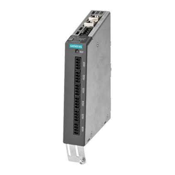
Page 15: Electrical Installation
Electrical installation Overview Figure 4-1 Terminal Module 150 (TM150) Terminal Module 150 (TM150) Operating Instructions, 03/2012, A5E03758735A... -
Page 16: Interface Description
Electrical installation 4.2 Interface description Interface description 4.2.1 X524 electronics power supply Table 4- 1 Terminal strip for the electronics power supply X524 Terminal Designation Technical data Electronic power supply Voltage: 24 V DC (20.4 V – 28.8 V) Current consumption: Max. 0.2 A Electronic power supply Max. -
Page 17: X531-X536 Temperature Sensor Inputs
Electrical installation 4.2 Interface description 4.2.3 X531-X536 temperature sensor inputs Table 4- 3 X531-X536 temperature sensor inputs Terminal Function Function Technical data 1x2- / 2x2-wire 3 and 4-wire +Temp Temperature sensor connection for sensors with (channel x) (channel x) 1x2 wires Connection of the 2nd measurement cable for sensors with 4-wires -Temp... -
Page 18: Meaning Of The Leds On The Terminal Module Tm150
Electrical installation 4.2 Interface description Table 4- 4 Channel assignment Terminal Channel number [x] Channel number [y] for 1x2, 3 and 4-wires for 2x2 wires X531 X532 X533 X534 X535 X536 NOTICE Cable cross section Cable length and cross section might influence the temperature measurement (10 Ω... -
Page 19: Connection Examples
Electrical installation 4.3 Connection examples Connection examples X53x X53x X53x Figure 4-2 Connecting a PT100/PT1000 with 2x2, 3 and 4-wires to the temperature sensor inputs X53x of Terminal Module TM150 Terminal Module 150 (TM150) Operating Instructions, 03/2012, A5E03758735A... - Page 20 Electrical installation 4.3 Connection examples Figure 4-3 Connection example for a Terminal Module TM150 Terminal Module 150 (TM150) Operating Instructions, 03/2012, A5E03758735A...
-
Page 21: Protective Conductor Connection And Shield Support
Electrical installation 4.4 Protective conductor connection and shield support Protective conductor connection and shield support The following diagram shows a typical Weidmüller shield connection clamp for the shield supports. ① Protective conductor connection M4/1.8 Nm ② Shield connection terminal, Weidmüller company, type: KLBÜ CO1, order number: 1753311001 Figure 4-4 Shield support and protective conductor connection of the TM150... - Page 22 Electrical installation 4.4 Protective conductor connection and shield support Terminal Module 150 (TM150) Operating Instructions, 03/2012, A5E03758735A...
-
Page 23: Technical Specifications
Technical specifications General technical data Table 5- 1 General technical data Product standard EN 61800-5-1 Technical data Table 5- 2 Technical data 6SL3055- 0AA0-3LA0 Unit Value Electronic power supply Voltage 24 V DC (20.4 – 28.8) Current (without DRIVE-CLiQ) 0.07 Power loss PE/ground connection On housing with M4/1.8 Nm screw... - Page 24 Technical specifications Terminal Module 150 (TM150) Operating Instructions, 03/2012, A5E03758735A...
- Page 26 Siemens AG Subject to change without prior notice Industry Sector © Siemens AG 2012 Drive Technologies Large Drives P.O. Box 4743 90025 NUREMBERG GERMANY www.siemens.com/automation...
Need help?
Do you have a question about the SINAMICS G130 and is the answer not in the manual?
Questions and answers