Sign In
Upload
Manuals
Brands
Siemens Manuals
Media Converter
SINAMICS G120X
Siemens SINAMICS G120X Manuals
Manuals and User Guides for Siemens SINAMICS G120X. We have
1
Siemens SINAMICS G120X manual available for free PDF download: Operating Instructions Manual
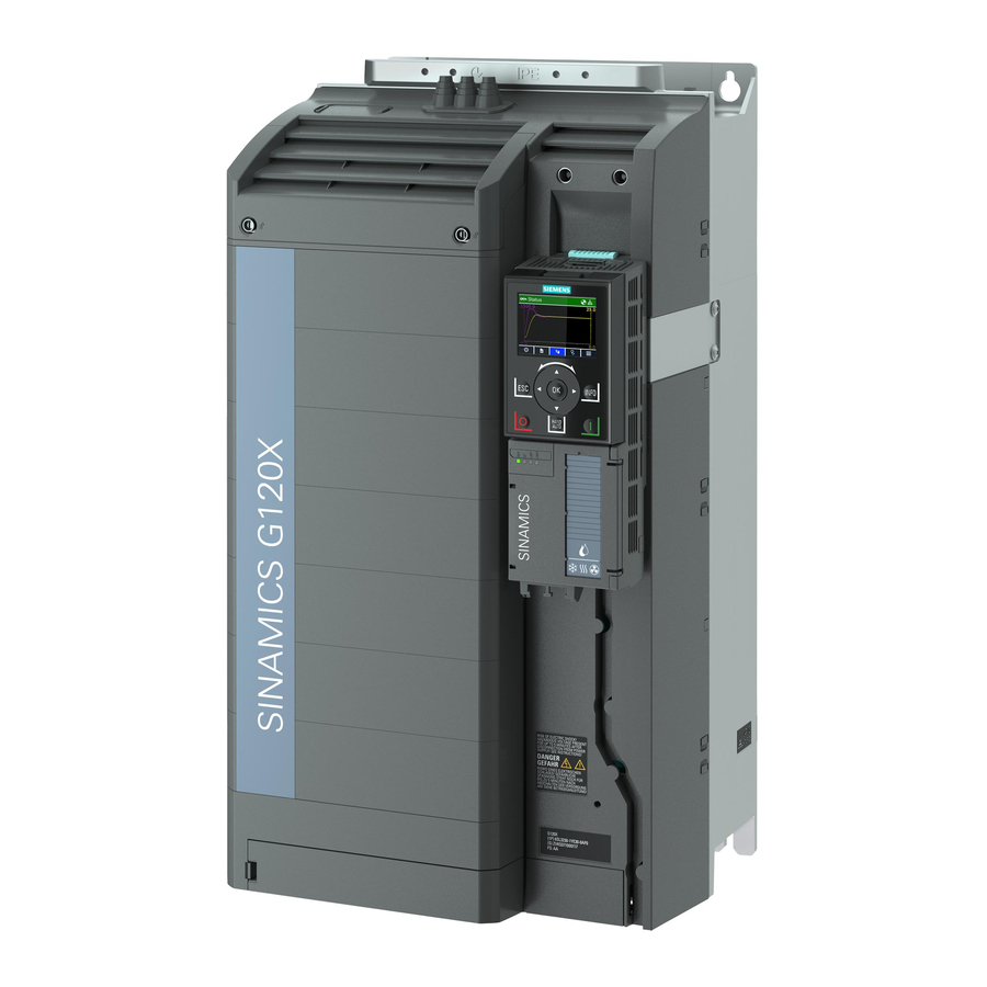
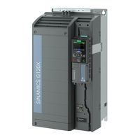
Siemens SINAMICS G120X Operating Instructions Manual (1148 pages)
Infrastructure converter for HVAC/water/wastewater
Brand:
Siemens
| Category:
Media Converter
| Size: 16.62 MB
Table of Contents
5
Table of Contents
13
1 Fundamental Safety Instructions
13
General Safety Instructions
19
Equipment Damage Due to Electric Fields or Electrostatic Discharge
20
Warranty and Liability for Application Examples
21
Industrial Security
23
Residual Risks of Power Drive Systems
25
Description
25
About the Manual
26
About the Converter
27
Scope of Delivery
31
Directives and Standards
33
Device Disposal
34
Optional Components
34
External Line Filter
35
Line Reactor
37
Line Harmonics Filter
38
Output Reactor
40
Sine-Wave Filter
41
DV/Dt Filter Plus VPL
43
Push-Through Mounting Kit
46
Mounting Grips for Push-Through Mounted Converters
46
IP21 Top Cover
47
Mounting Kit for Line-Side Cable Connection, Left (FSH Only)
47
I/O Extension Module
49
Operator Panel
50
SINAMICS G120 Smart Access
51
Motors and Multi-Motor Drives That Can Be Operated
53
Mounting
53
Installing the Label for the North American Market
54
Emc-Compliant Setup of the Machine or Plant
55
Control Cabinet
56
Cables
58
Electromechanical Components
59
Power Losses and Air Cooling Requirements
61
Mounting the Converter
61
Basic Installation Rules
63
Dimension Drawings and Drill Patterns
64
Mounting the Converter On the Mounting Panel
66
Mounting the Converter Utilizing Push-Through Technology (FSA to FSG Only)
69
Mounting the Shield Connection Kits
71
Additional Mounting Instructions for FSD
71
Additional Mounting Instructions, FSD
74
Additional Mounting Instructions, FSH/FSJ
75
Mounting the Optional Components
77
4 Wiring
77
Line Supply and Motor
77
Permissible Line Supplies
77
TN System
79
TT System
80
IT System
80
Removing Functional Grounding of the Converter
82
Minimum Cross-Section of the Protective Conductor
84
Maximum Permissible Motor Cable Length
89
Connecting the Converter and Converter Components
90
Connection Overview
91
Connnecting Converters
96
Cable Cross-Sections and Screw Tightening Torques
97
Cable Lug
98
Connecting the Cable Shields (FSA
100
Connecting the Motor to the Converter in a Star or Delta Connection
101
Control Interfaces
101
Overview of the Interfaces
102
Fieldbus Interface Allocation
103
Terminal Strips
105
Terminals Strips for I/O Extension Module
107
Factory Interface Settings
109
Default Setting of the Interfaces (Macros)
128
Additional Digital Inputs and Digital Outputs On Converters FSH and FSJ
130
Safe Torque Off" Safety Function
134
Application Examples for "Safe Torque Off
141
Wiring the Terminal Strips
143
Connecting to PROFINET and Ethernet
143
Communication Via PROFINET IO and Ethernet
144
Protocols Used
146
Connecting the PROFINET Cable to the Converter
146
What Do You Have to Set for Communication Via PROFINET
147
Installing GSDML
147
Connect Converter to Ethernet/Ip
148
What Do You Need for Communication Via Ethernet/Ip
148
RS485 Interface for the Fieldbus
149
Connecting to PROFIBUS
150
Connecting the PROFIBUS Cable to the Converter
150
What Do You Have to Set for Communication Via PROFIBUS
151
Installing the GSD
153
5 Commissioning
153
Commissioning Guidelines
154
Tools
155
Preparing for Commissioning
155
Collecting Motor Data
157
Forming DC Link Capacitors
159
Converter Factory Setting
161
Quick Commissioning Using the BOP-2 Operator Panel
161
Fitting the BOP-2 to the Converter
162
Overview of Quick Commissioning
163
Start Quick Commissioning and Select the Application Class
164
Selecting an Application Class
165
Standard Drive Control
167
Dynamic Drive Control
169
Expert
173
Identifying the Motor Data and Optimizing the Closed-Loop Control
175
Restoring the Factory Settings
176
Handling the BOP-2 Operator Panel
177
Changing Settings Using BOP-2
178
Changing Indexed Parameters
179
Directly Entering the Parameter Number and Value
180
A Parameter Cannot Be Changed
181
6 Advanced Commissioning
181
Overview of the Converter Functions
183
Brief Description of the Parameters
184
Drive Control
184
Sequence Control When Switching the Motor On and Off
188
Adapt the Default Setting of the Terminal Strips
190
Digital Inputs
193
Analog Input As Digital Input
195
Digital Outputs
198
Analog Inputs
201
Adjusting Characteristics for Analog Input
202
Setting the Deadband
204
Analog Outputs
207
Adjusting Characteristics for Analog Output
208
Drive Control Via PROFINET or PROFIBUS
208
Setting the Address
208
Receive Data and Send Data
209
Telegrams
215
Parameter Channel
220
Expanding or Freely Interconnecting Telegrams
222
Acyclically Reading and Writing Converter Parameters
222
Reading and Changing Parameters Via Data Set 47
226
Drive Control Via Ethernet/Ip
227
Configuring Communication Via Ethernet/Ip
228
Supported Objects
242
Create Generic I/O Module
243
The Converter As Ethernet Node
244
Drive Control Via Modbus RTU
244
Activating Communication Via Fieldbus
246
Setting the Address
246
Parameters for Setting Communication Via Modbus RTU
249
Modbus RTU Telegram
250
Baud Rates and Mapping Tables
252
Mapping Tables - Converter Data
255
Acyclic Communication Via Modbus RTU
256
Write and Read Access Using Function Codes
258
Reading and Writing Parameters Acyclically Via FC 16
261
Communication Procedure
262
Application Example
263
Drive Control Via USS
263
Activating Communication Via Fieldbus
264
Setting the Address
264
Telegram Structure
265
Specify User Data of Telegram
266
USS Process Data Channel (PZD)
269
Telegram Monitoring
270
USS Parameter Channel
276
Drive Control Via Bacnet MS/TP
276
Bacnet Properties
277
Activating Communication Via Fieldbus
278
Setting the Address
279
Parameters for Setting Communication Via Bacnet
281
Supported Services and Objects
290
Acyclic Communication (General Parameter Access) Via Bacnet
292
Jogging
294
Switching Over the Drive Control (Command Data Set)
296
Selecting Physical Units
296
Motor Standard
296
Unit System
297
Technological Unit of the Technology Controller
298
Safe Torque Off (STO) Safety Function
300
Setting the Feedback Signal for Safe Torque Off
302
Pump Control
302
Multi-Pump Control
305
Pump Switch-In/Switch-Out
310
Stop Mode
313
Pump Switchover
315
Service Mode
318
Frost Protection
320
Condensation Protection
322
Cavitation Protection
324
Deragging
326
Pipe Filling
329
Setpoints and Setpoint Processing
329
Setpoints
330
Analog Input As Setpoint Source
331
Specifying the Setpoint Via the Fieldbus
332
Motorized Potentiometer As Setpoint Source
335
Fixed Speed Setpoint As Setpoint Source
340
Setpoint Processing
340
Overview
341
Invert Setpoint
342
Enable Direction of Rotation
343
Skip Frequency Bands and Minimum Speed
346
Speed Limitation
347
Ramp-Function Generator
350
Dual Ramp Function
352
Technology Controller
352
PID Technology Controller
363
Autotuning the PID Technology Controller
366
Adapting Kp and Tn
369
Free Technology Controllers
370
Cascade Control
375
Real Time Clock (RTC)
377
Time Switch (DTC)
378
Motor Control
378
Reactor, Filter and Cable Resistance at the Converter Output
379
V/F Control
379
U/F Control
384
Optimizing Motor Starting
389
U/F Control with Standard Drive Control
391
Optimizing the Motor Start-Up for Application Class Standard Drive Control
393
Encoderless Vector Control
393
Structure of Vector Control Without Encoder (Sensorless)
398
Optimizing the Speed Controller
400
Electrically Braking the Motor
402
DC Braking
404
Compound Braking
405
Pulse Frequency Wobbling
406
Drive Protection
406
Overcurrent Protection
408
Converter Protection Using Temperature Monitoring
411
Motor Protection with Temperature Sensor
414
Motor Protection By Calculating the Temperature
416
Motor and Converter Protection By Limiting the Voltage
417
Monitoring the Driven Load
419
Stall Protection
419
No-Load Monitoring
420
Blocking Protection
421
Torque Monitoring
422
Blocking Protection, Leakage Protection and Dry-Running Protection
424
Rotation Monitoring
425
Drive Availability
425
Flying Restart - Switching On While the Motor Is Running
427
Automatic Restart
430
Kinetic Buffering (VDC Min Control)
431
Essential Service Mode
436
Energy Saving
436
Efficiency Optimization
439
ECO Mode
441
Bypass
447
Hibernation Mode
453
Line Contactor Control
455
Calculating the Energy Saving for Fluid Flow Machines
457
Flow Meter
458
Profienergy
459
Control Commands
460
Status Queries
460
Error Values and Measured Values
462
Switchover Between Different Settings
464
Explanations of the Function Diagrams
464
Symbols in the Function Diagrams
466
Interconnecting Signals in the Converter
469
7 Parameters
469
Explanation of the Detailed Parameter List
472
Parameter List
938
ASCII Table
941
8 Saving the Settings and Series Commissioning
942
Memory Card
942
Recommended Memory Cards
942
Saving Setting On a Memory Card
943
Automatic Backup
944
Manual Backup
944
Transferring the Setting From the Memory Card
944
Automatic Transfer
945
Manually Transferring
946
Safely Remove the Memory Card
947
Message for a Memory Card That Is Not Inserted
948
Operator Panel
948
Backup Using the Operator Panel
948
Transfer to the Converter
950
Other Ways to Back Up Settings
951
Series Commissioning
952
Write Protection
954
Know-How Protection
957
Extending the Exception List for Know-How Protection
958
Activating and Deactivating Know-How Protection
961
9 Warnings, Faults and System Messages
962
Operating States Indicated On Leds
964
System Runtime
965
Identification & Maintenance Data (I&M)
1077
Upgrading the Firmware
1083
Technical Data
1094
Derating Data
Advertisement
Share and save
Advertisement
Related Products
Siemens SINAMICS G12
Siemens SINAMICS G120C DP
Siemens SINAMICS G120C PN
Siemens SINAMICS G120XA
Siemens SINAMICS G150
Siemens SINAMICS G130
Siemens SINAMICS G110D 6SL3511-0PE17-5AM0
Siemens SINAMICS G110D 6SL3511-0PE25-5AM0
Siemens SINAMICS G110D 6SL3511-0PE27-5AM0
Siemens SINAMICS G110D 6SL3511-0PE24-0AM0
Siemens Categories
Control Unit
Controller
Measuring Instruments
Telephone
Cell Phone
More Siemens Manuals
×
Login
Sign In
OR
Sign in with Facebook
Sign in with Google
×
Upload manual
Upload from disk
Upload from URL