Table of Contents
Advertisement
GE Healthcare
Senographe DS
Service Information and Procedures Class A
SIP-A
0459
The page behind contains quick access links to commonly used information.
Use these
Favorite Links
Copyright© 2012 by General Electric Company inc. All rights reserved.
when attempting to find information.
2385072-16-8EN
Revision 1
Advertisement
Table of Contents
Troubleshooting

Related Manuals for GE Senographe DS


Summary of Contents for GE Senographe DS
- Page 1 GE Healthcare Senographe DS Service Information and Procedures Class A SIP-A The page behind contains quick access links to commonly used information. 0459 Use these Favorite Links when attempting to find information. 2385072-16-8EN Revision 1 Copyright© 2012 by General Electric Company inc. All rights reserved.
- Page 2 GE Healthcare Senographe DS Revision 1 Service Information and Procedures Class A 2385072-16-8EN This page is blank. Page no. 2 coverDS-SIP-Class-A.fm...
-
Page 3: Favorite Links For Field Engineers
GE Healthcare Senographe DS Revision 1 Service Information and Procedures Class A 2385072-16-8EN Favorite Links for Field Engineers Favorite Links for Field Engineers Use these links for quick access to frequently used information in the SIP: Functional diagrams Acquisition System Entry Block Diagram on page 74... - Page 4 GE Healthcare Senographe DS Revision 1 Service Information and Procedures Class A 2385072-16-8EN Favorite Links for Field Engineers This page is blank. Page no. 4 Favorites for FE.fm...
-
Page 5: Table Of Contents
GE Healthcare Senographe DS Revision 1 Service Information and Procedures Class A 2385072-16-8EN Table of Contents Table of Contents Favorite Links for Field Engineers .......... - Page 6 GE Healthcare Senographe DS Revision 1 Service Information and Procedures Class A 2385072-16-8EN Table of Contents 3. How to Use the Browser ..........
- Page 7 GE Healthcare Senographe DS Revision 1 Service Information and Procedures Class A 2385072-16-8EN Table of Contents 4. Structural Requirements ..........332 5.
- Page 8 GE Healthcare Senographe DS Revision 1 Service Information and Procedures Class A 2385072-16-8EN Table of Contents Scenario ELE A001 - Electrical Installation ........
- Page 9 GE Healthcare Senographe DS Revision 1 Service Information and Procedures Class A 2385072-16-8EN Table of Contents ERR SUB A005 - AWS Error Messages ......... 935 ERR SUB A007 - IDC Error Messages.
- Page 10 GE Healthcare Senographe DS Revision 1 Service Information and Procedures Class A 2385072-16-8EN Table of Contents Job Card D/R A215 - Arm Control Keypad Cables ....... . 1217 Job Card D/R A216 - Arm Control Keypads .
- Page 11 GE Healthcare Senographe DS Revision 1 Service Information and Procedures Class A 2385072-16-8EN Table of Contents Job Card D/R A317 - Radiation Screen......... . 1463 Job Card D/R A318 - LCD Monitor.
- Page 12 GE Healthcare Senographe DS Revision 1 Service Information and Procedures Class A 2385072-16-8EN Table of Contents Job Card CAL A048 - Calibration of Compression Force Sensor ....1709 Job Card CAL A049 - Compression Paddle Offset Calibration .
-
Page 13: Chapter 1 Safety
GE Healthcare Senographe DS Revision 1 Service Information and Procedures Class A 2385072-16-8EN Safety CHAPTER 1 SAFETY This chapter contains information and warnings related to safety. Page no. 13 Chapter 1 Chap-Safety.fm... - Page 14 GE Healthcare Senographe DS Revision 1 Service Information and Procedures Class A 2385072-16-8EN Safety This page is blank. Chapter 1 Page no. 14 Chap-Safety.fm...
-
Page 15: Language Warning
GE Healthcare Senographe DS Revision 1 Service Information and Procedures Class A 2385072-16-8EN Language Warning Language Warning Chapter 1 ПРЕДУПРЕЖДЕНИЕ Това упътване за работа е налично само на английски език. • Ако доставчикът на услугата на клиента изиска друг език, (BG) задължение... - Page 16 GE Healthcare Senographe DS Revision 1 Service Information and Procedures Class A 2385072-16-8EN Language Warning VÝSTRAHA Tento provozní návod existuje pouze v anglickém jazyce. • V případě, že externí služba zákazníkům potřebuje návod v jiném (CS) jazyce, je zajištění překladu do odpovídajícího jazyka úkolem zákazníka.
- Page 17 Serviceanleitung gelesen und verstanden zu haben. • Wird diese Warnung nicht beachtet, so kann es zu Verletzungen des Kundendiensttechnikers, des Bedieners oder des Patienten durch Stromschläge, mechanische oder sonstige Gefahren kommen. ΠΡΟΕΙΔΟΠΟΙΗΣΗ Το παρόν εγχειρίδιο σέρβις διατίθεται μόνο στα αγγλικά.
- Page 18 GE Healthcare Senographe DS Revision 1 Service Information and Procedures Class A 2385072-16-8EN Language Warning AÐVÖRUN Þessi þjónustuhandbók er aðeins fáanleg á ensku. • Ef að þjónustuveitandi viðskiptamanns þarfnast annas tungumáls en (IS) ensku, er það skylda viðskiptamanns að skaffa tungumálaþjónustu.
- Page 19 GE Healthcare Senographe DS Revision 1 Service Information and Procedures Class A 2385072-16-8EN Language Warning ADVARSEL Denne servicehåndboken finnes bare på engelsk. • Hvis kundens serviceleverandør har bruk for et annet språk, er det (NO) kundens ansvar å sørge for oversettelse.
- Page 20 GE Healthcare Senographe DS Revision 1 Service Information and Procedures Class A 2385072-16-8EN Language Warning ОСТОРОЖНО! Данное руководство по техническому обслуживанию представлено только на английском языке. (RU) • Если сервисному персоналу клиента необходимо руководство не на английском, а на каком-то другом языке, клиенту следует...
- Page 21 GE Healthcare Senographe DS Revision 1 Service Information and Procedures Class A 2385072-16-8EN Language Warning OPOZORILO Ta servisni priročnik je na voljo samo v angleškem jeziku. • Če ponudnik storitve stranke potrebuje priročnik v drugem jeziku, mora (SL) stranka zagotoviti prevod.
- Page 22 GE Healthcare Senographe DS Revision 1 Service Information and Procedures Class A 2385072-16-8EN Language Warning This page is blank. Chapter 1 Page no. 22 language warning.fm...
-
Page 23: X-Ray Warning
GE Healthcare Senographe DS Revision 1 Service Information and Procedures Class A 2385072-16-8EN X-ray Warning X-ray Warning Chapter 1 ATTENTION Les appareils à rayons X sont dangereux à la fois pour le patient et pour le manipulateur si les mesures de protection ne sont pas strictement appliquees Bien que cet appareil soit construit selon les normes de sécurité... - Page 24 GE Healthcare Senographe DS Revision 1 Service Information and Procedures Class A 2385072-16-8EN X-ray Warning This page is blank. Chapter 1 Page no. 24 radiation warning.fm...
-
Page 25: Definition Of Warnings And Notes
GE Healthcare Senographe DS Revision 1 Service Information and Procedures Class A 2385072-16-8EN Definition of Warnings and Notes Definition of Warnings and Notes Chapter 1 DANGER Indicates an imminently hazardous situation that, if not avoided, will result in death or seri- ous injury. - Page 26 GE Healthcare Senographe DS Revision 1 Service Information and Procedures Class A 2385072-16-8EN Definition of Warnings and Notes Meaning of Symbols The following symbols may appear on parts of the Senographe System. Alternating current Earth (ground) Dangerous voltage Type B equipment...
-
Page 27: Chapter 2 Publication Presentation
It is intended for use by Field Engineers installing and maintaining the system who are employed by: • GEMS. • A third party supplier with an agreed contract with GE. • A third party supplier without an agreed contract with GE. CONTENT OF THIS PUBLICATION 2-1. - Page 28 GE Healthcare Senographe DS Revision 1 Service Information and Procedures Class A 2385072-16-8EN Publication Presentation 2-4-2. Procedural Instructions • Procedural instructions are given in three types of document: Error message lists, Scenarios, and Job Cards: 2-4-2-1 Error Message Lists •...
- Page 29 GE Healthcare Senographe DS Revision 1 Service Information and Procedures Class A 2385072-16-8EN Publication Presentation 2-4-3. Job Card and Scenario Categories Category definition Scope code code Pre-installation Includes wall, ceiling, and floor preparation, electrical cabling, etc. System Physical Installation First installation on Customer site – Physical installation step = without powering-on the equipment.
-
Page 30: Publication Conventions
GE Healthcare Senographe DS Revision 1 Service Information and Procedures Class A 2385072-16-8EN Publication Presentation PUBLICATION CONVENTIONS 3-1. Typographical Convention • In text describing the user interface, italic and bold characters differentiate between body text and on-screen or hardware captions and labels, entered text, etc.: Italics are used for references to hardware items and text which appears on-screen (e.g., menu... -
Page 31: How To Navigate Using Acrobat
GE Healthcare Senographe DS Revision 1 Service Information and Procedures Class A 2385072-16-8EN Publication Presentation HOW TO NAVIGATE USING ACROBAT Note: The appearance and position of the navigation buttons referred to here can vary slightly, according to your version of Adobe Reader and its configuration. - Page 32 GE Healthcare Senographe DS Revision 1 Service Information and Procedures Class A 2385072-16-8EN Publication Presentation ILLUSTRATION 1 - HOW TO NAVIGATE IN THE SIP Direct access tools Table of contents Bookmarks Favorites pages Component Location Diagrams Product History Glossary Component Cable Layout...
- Page 33 GE Healthcare Senographe DS Revision 1 Service Information and Procedures Class A 2385072-16-8EN Publication Presentation ILLUSTRATION 2 - USE BOOKMARKS Page no. 33 Chapter 2 Publication Presentation.fm...
- Page 34 GE Healthcare Senographe DS Revision 1 Service Information and Procedures Class A 2385072-16-8EN Publication Presentation This page is blank. Chapter 2 Page no. 34 Publication Presentation.fm...
-
Page 35: Acronyms Glossary
GE Healthcare Senographe DS Revision 1 Service Information and Procedures Class A 2385072-16-8EN Acronyms Glossary Acronyms Glossary Chapter 2 Alternating Current Appollo Digital System Application Entity Title Analog Readout Chip ASIS Application Specific Integrated Circuit Acquisition Workstation Advantage Window Analog to Digital... - Page 36 GE Healthcare Senographe DS Revision 1 Service Information and Procedures Class A 2385072-16-8EN Acronyms Glossary Functional Diagram Food and Drug Administration Field Engineer Field Effect Transistor FFDM Full Field Digital Mammography Field Modification Instruction Field Of View FPGA Field Programmable Gate Array...
- Page 37 GE Healthcare Senographe DS Revision 1 Service Information and Procedures Class A 2385072-16-8EN Acronyms Glossary Main Contactor Micro Controller Unit (usually refers to the HC12 chip on the Gantry nodes) MulitChip Module Main Distribution Rack Main Functional Unit MQSA Mammography Quality Standards Act...
- Page 38 GE Healthcare Senographe DS Revision 1 Service Information and Procedures Class A 2385072-16-8EN Acronyms Glossary Single Board Computer Scenario Categories Service Class Provider Service Class User Source to Dosimeter Distance Select Source to Image Distance Service Information and Procedures SLDU...
-
Page 39: Revision History
GE Healthcare Senographe DS Revision 1 Service Information and Procedures Class A 2385072-16-8EN Revision History Revision History Chapter 2 Note for the Technical Writer: This publication is contained in a multibook Master folder. It is a slave publication. To maintain this publication it is mandatory to use “Master Folder” 2396423–x–8EN as the Frame Maker source. - Page 40 GE Healthcare Senographe DS Revision 1 Service Information and Procedures Class A 2385072-16-8EN Revision History This page is blank. Chapter 2 Page no. 40 Revision history.fm...
-
Page 41: Chapter 3 System Description
GE Healthcare Senographe DS Revision 1 Service Information and Procedures Class A 2385072-16-8EN System Description CHAPTER 3 SYSTEM DESCRIPTION This chapter contains descriptive information for the Senographe system. Page no. 41 Chapter 3 Chap-System Description.fm... - Page 42 GE Healthcare Senographe DS Revision 1 Service Information and Procedures Class A 2385072-16-8EN System Description This page is blank. Chapter 3 Page no. 42 Chap-System Description.fm...
-
Page 43: Sub-Systems And Components
GE Healthcare Senographe DS Revision 1 Service Information and Procedures Class A 2385072-16-8EN Sub-Systems and Components Sub-Systems and Components Chapter 3 Senographe Acquisition System: Gantry Definitions: Gantry = Arm + Column + Image Receptor Arm = Tube Head + Compression Arm... -
Page 44: System Features
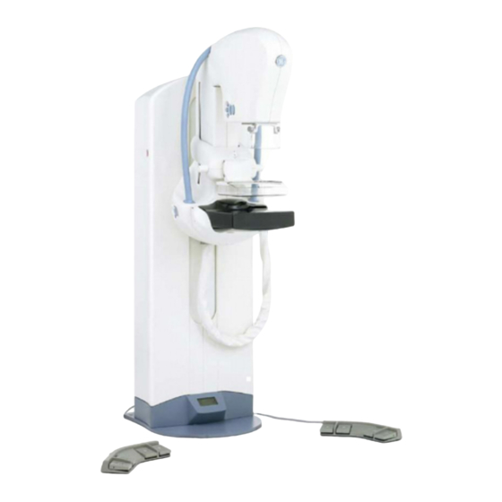
Sub-Systems and Components SYSTEM FEATURES Senographe DS is one of the latest Digital Mammography Systems from GE Medical Systems. It has been designed to perform Screening examinations as well as Diagnostic Views (including Spot compres- sion, Magnified and/or Coned views). It is a modular system that eliminates the need for film cassettes. It takes advantage of digital technology, including on-screen image display, Networking, Filming, and Archiving. -
Page 45: System Component Description
GE Healthcare Senographe DS Revision 1 Service Information and Procedures Class A 2385072-16-8EN Sub-Systems and Components SYSTEM COMPONENT DESCRIPTION Gantry Control Station Radiation screen Generator Cabinet LCD monitor Position for mouse or optional track- ball (not shown) Digital Detector X-ray Console AWS Cabinet 2-1. - Page 46 GE Healthcare Senographe DS Revision 1 Service Information and Procedures Class A 2385072-16-8EN Sub-Systems and Components 2-2. Senographe X-ray System The Senographe is equipped with a dual track X-ray tube (molybdenum/rhodium) and a Digital Detector. Mammographic examinations can be made with standing, sitting, or recumbent patients; both contact and magnification views are available.
- Page 47 GE Healthcare Senographe DS Revision 1 Service Information and Procedures Class A 2385072-16-8EN Sub-Systems and Components 2-4. Control Station Radiation screen LCD Monitor X-ray Console mounted on top of the cabinet Mouse or optional trackball AWS keyboard pulls out from top of cabinet...
- Page 48 GE Healthcare Senographe DS Revision 1 Service Information and Procedures Class A 2385072-16-8EN Sub-Systems and Components 2-4-2. Uninterruptible Power Supply (UPS) To assure system safety in the event of disturbances in the mains power supply, the Senographe system incorporates a UPS, housed in the Control Station cabinet.
-
Page 49: Accessories
3-1. Senographe DS Accessories • The Senographe DS is delivered with a standard 19 x 23 paddle for use with the Bucky. The follow- ing accessories may be standard or optional according to country: 19 x 23 cm standard magnification paddle. - Page 50 GE Healthcare Senographe DS Revision 1 Service Information and Procedures Class A 2385072-16-8EN Sub-Systems and Components other compliant devices for the exchange of images. Networking allows transmission of images acquired with the Senographe system to other DICOM-compatible review workstations, using the “Network Push”...
-
Page 51: Product History And Compatibility
How to Identify Your System As the Senographe DS system evolves, successive manufacturing versions exist for the same system name. You can identify the manufacturing version of your Senographe DS system by viewing the follow- ing two items together: •... - Page 52 GE Healthcare Senographe DS Revision 1 Service Information and Procedures Class A 2385072-16-8EN Product history and compatibility How to Identify The Model Number ILLUSTRATION 1 - LOCATION OF SYSTEM IDENTIFICATION LABEL - PRE-PENDUICK SYSTEMS Upto and including Nephtys M5A Model number...
- Page 53 GE Healthcare Senographe DS Revision 1 Service Information and Procedures Class A 2385072-16-8EN Product history and compatibility ILLUSTRATION 2 - LOCATION OF SYSTEM IDENTIFICATION LABEL - PENDUICK AND ABOVE SYSTEMS Generator HV Tank System ID CDRH ID CDRH Identification System Identification Label Model Number Page no.
- Page 54 GE Healthcare Senographe DS Revision 1 Service Information and Procedures Class A 2385072-16-8EN Product history and compatibility Control Station Identification Different Control Stations can exist for the same system name. Consequently you may need to identify your type of Control Station if you are changing a particular component on the Control Station.
- Page 55 GE Healthcare Senographe DS Revision 1 Service Information and Procedures Class A 2385072-16-8EN Product history and compatibility 2-3-5 Accelera Upgraded Control Stations Some V2 Control Stations have been upgraded to V3 Control Stations, using the Accelera Upgrade Kit. Upgraded Control Stations contain FRUs specific to the Accelera upgrade (such as a VGA-DVI Adaptor, ADS-UPS Extension cable, and Ferrite Blocks), which are denoted by the compatibility code Acc.
- Page 56 AWS Application Software Versions The following table summarizes each of the different model numbers and AWS Application Software ver- sion for each manufacturing version for each manufacturing version for the Senographe DS system, and the location of the identification label.
- Page 58 Note: During June 2011, forward production systems had a new Type 3 Lift Screw Assembly with Motor Brake introduced in the Gantry.
- Page 59 Lift Board (2373567-8) with firmware CPLD 10.0.1. The introduction of a new Bucky and the possibility to order the Bucky board as a FRU. Reduction of the number of core systems from two to one; only the Senographe DS International (2383168-4-1) exists.
- Page 60 GE Healthcare Senographe DS Revision 1 Service Information and Procedures Class A 2385072-16-8EN Product history and compatibility 3-1-4 Nephtys M410 (IS4-3 FMI 12075) • The AWS Application Software for the V3 Control Stations (U20 Workstation) was updated from V53.0 to V53.10.1.
- Page 61 GE Healthcare Senographe DS Revision 1 Service Information and Procedures Class A 2385072-16-8EN Product history and compatibility 3-1-9 Nephtys M414 (Penduick) • New and improved Gantry Boards, as follows: Gantry CPU Board with NSC.1.2.15 (5233827-8) Lift Board with HC12: V5.16.2 (2373567-11) Rotation Board with HC12: V5.12.4 (2375488-13)
- Page 62 GE Healthcare Senographe DS Revision 1 Service Information and Procedures Class A 2385072-16-8EN Product history and compatibility 3-1-11 Nephtys M415 (Z400) - Q3/Q4 2011 During Q3 2011, the following non-software related changes were made to the system: • Forward production Gantries include a new "Type 3" Lift Screw Assembly with an integrated Motor Brake.
- Page 63 GE Healthcare Senographe DS Revision 1 Service Information and Procedures Class A 2385072-16-8EN Product history and compatibility COMPONENT FW/SW TO ADS VERSION COMPATIBILITY MATRIX The components in the Senographe system must have a certain version of firmware or software in order to work correctly at a particular system level.
- Page 64 GE Healthcare Senographe DS Revision 1 Service Information and Procedures Class A 2385072-16-8EN Product history and compatibility Component CESM1 Pixel Spacing CESM 2 Sunburst (Optional (FMI 12166) (Optional Upgrade) Upgrade) ADS Hardware Computer U20 or Z400 U20 or Z400 U20 or Z400...
- Page 65 GE Healthcare Senographe DS Revision 1 Service Information and Procedures Class A 2385072-16-8EN Product history and compatibility Gantry Boards To simplify Gantry FRU management, only one version of each Gantry Board (i.e. Gantry CPU, Inter- face, Rotation, Lift, Compression, Tilt, Collimator, PDU, and Bucky) is available, and is based on the most common system level in the install base (currently IS4-3 Forward Production).
- Page 66 GE Healthcare Senographe DS Revision 1 Service Information and Procedures Class A 2385072-16-8EN Product history and compatibility Empty Generator CPU Board and EEPROM Kits In the past, different Generator CPU Boards (containing EEPROMs) for different system levels were available as a FRU. Now the strategy has changed, such that an empty Generator CPU Board exists (P/N 5399150), and EEPROM Kits with different part numbers exist for different system levels.
- Page 67 GE Healthcare Senographe DS Revision 1 Service Information and Procedures Class A 2385072-16-8EN Product history and compatibility IDC and ADS Software Kit Different IDC and ADS Software kits are available as a FRU. To determine which IDC and ADS Software kits you need to order, do the following: 1.
- Page 68 GE Healthcare Senographe DS Revision 1 Service Information and Procedures Class A 2385072-16-8EN Product history and compatibility COMPATIBILITY CODES • Because of continuous product evolution, the components and procedures used may change from time to time. New versions are not always compatible with the old, and this means that some compo- nents and procedures should be used only with certain versions of the product.
- Page 69 GE Healthcare Senographe DS Revision 1 Service Information and Procedures Class A 2385072-16-8EN Product history and compatibility Changes introduced in the Field In addition to changes introduced in manufacturing, some components and procedures may be affected by changes in the field. A component might be usable on a system as delivered from the factory, but not on the same system after application of a specified FMI or component replacement.
- Page 70 GE Healthcare Senographe DS Revision 1 Service Information and Procedures Class A 2385072-16-8EN Product history and compatibility This page is blank. Chapter 3 Page no. 70 Product-historyDS.fm...
-
Page 71: Functional Diagrams
GE Healthcare Senographe DS Revision 1 Service Information and Procedures Class A 2385072-16-8EN Functional Diagrams Functional Diagrams Chapter 3 INTRODUCTION 1-1. Purpose of this section This is a functional description of the complete system; it is split into several block diagrams with hyper- text links. -
Page 72: Correspondence Between Functions And Components
GE Healthcare Senographe DS Revision 1 Service Information and Procedures Class A 2385072-16-8EN Functional Diagrams CORRESPONDENCE BETWEEN FUNCTIONS AND COMPONENTS Functions Second Level Functions Third Level Functions Corresponding Compo- nent Found in Acquisition System Entry Block Dia- gram on page 74... -
Page 73: Symbols
Generator Circuit board assembly Gantry main units Cable conduit Physical component assembly Connector Set of components belonging to the same function DC Motor Stepper motor Bulkhead Area Electrical connection Fiber‐optic cable Water hoses Manual operation... - Page 74 Gantry Generator Cabinet Column Conditioner Rack Detector cooling Conditioner Conditioner Control MPCB Detector ac supply Mammo AC UPS Power and Main Distribution Link Control Box Tube Head Generator Filter wheel HV cable Detector Service Collimator HV Tank 701 W412 Network supply To X-ray Tube 300 PL2...
-
Page 75: Mpcb Block Diagram
Comp. Arm W315 EMC W112 Arm Distrib.B. 48 Vdc2 (‐) filter W314 W113 48 Vdc3 Arm Distrib.B. Shunt W109 E102 F1/1 F1/2 R101 Column W108 F2/2 F2/1 W210 48vdc HP W117 Lift + Rot. Nd. W105 Lift + Rot. Nd. Terminal block ST102 W216 W111 E.Stop R‐Butt. W217 E.Stop L‐Butt. W208 W110 48vdc LP Lift + Rot. Nd. AC/DC Module W402 To XR Tube AC/DC Board Tube ... -
Page 76: Column Block Diagram
Stop Motion S205 Button - Right MPCB Stop Motion W216 S206 Button - Left W217 W220 R202 Potentiometer Terminal block W206 M201 ST102 W205 Encoder U201 W218 W221 B201 Clutch PDU Board W219 PL101 B202 Brake W215 S203 Opt. fork Board Interface Board... -
Page 77: Compression Arm Block Diagram
MPCB Tube Head SYS POS Bus From PL104 W409 SYS Bus2 To Colim. PL403 Interf. Board J5 48vdc-LP2 W401 From PL101 48vdc-LP2 To Colim. PL402 PDU Board J6 POS Bus2 W411 Tilt Board PL401 Bucky Assembly 48vdc-LP2 W311 W410 Tilt Board PL401 W310 Bucky Force Sensor... -
Page 78: Tube Head Block Diagram
Arm Control Keypads Compression (left and right of tube head) Right W407 W410 48vdc-LP2 PL404 From Distrib. W411 POS-Bus 2 Board PL301 Left W407 PL404 From GND Bar G301 X-Ray tube support Tilt Board W406 V401 From Distrib. PL401 Board PL301 W405 W413 S401... -
Page 79: Collimator Block Diagram
Collimator with Falhauber motors DC/DC W502 W503 Light Assembly Board W401 48Vdc-LP2 PL402 Collimator Filter Wheel Rectangular Blade Unit Assy. M4 S4 M3 S3 M2 S2 M1 S1 Collimator Set W506 (Falhauber motors) W504 (single FRU) M4 S4 M3 S3 M2 S2 M1 S1 Control W409 W501... -
Page 80: Main Distribution And Conditioner Block Diagram
Operator Main Hospital AC Supply Generator cabinet Power Line Filter Conditioner Rack Mains Mains Circuit Distribution Breaker 200 PL1 TRANSFO 2kVA Conditioner MPCB Generator AC IEC 320C1 4/ Bulkhead Conditioner 10 Plug Ground area Conditioner From control Mains Distribution Water Detector Assembly AC Detector PS Line Filter To IEC 320C1 4/ 250V 10 Plug Detector Interface FFDM Main Board ... -
Page 81: Generator Block Diagram
to Anode Starter Stator 0 V, + 250 Vdc Ext. Seno On Lamp Relay Board Motor to/from Board Ext. X‐Ray On Lamp 300 PL2 X‐Ray from BT Power 200 PL4 Room X‐ray Ext. Room Door Switch Supply 5 V, +/‐12 V Console Optical Fibers from 400 T1 Gantry 0 V, + 250 V DC XJ6 XJ7 XJ9 Generator To XJ11 Command Generator XJ10 Board C1‐P Interface XJ10 C1‐M 400 PL2 400 PL1 Supply Command ... -
Page 82: 12. Control Station Block Diagram
GE Healthcare Senographe DS Revision 1 Service Information and Procedures Class A 2385072-16-8EN Functional Diagrams 12. CONTROL STATION BLOCK DIAGRAM 12-1. Control Station Data Distribution Diagram (CS V1/V2) MODEM External Ethernet Keyboard RJ45 Trackball Serial A Main A Monitor VIDEO... - Page 83 GE Healthcare Senographe DS Revision 1 Service Information and Procedures Class A 2385072-16-8EN Functional Diagrams 12-2. Control Station Data Distribution Diagram (CS V3 - Pre-Penduick) External Ethernet Keyboard Mouse 26pts 50pts 2387162 Monitor COM2 RJ45 5177284-2 net0 net1 PCIe RJ45...
- Page 84 GE Healthcare Senographe DS Revision 1 Service Information and Procedures Class A 2385072-16-8EN Functional Diagrams 12-3. Control Station Data Distribution Diagram (CS V3 - Penduick and above) External Keyboard Ethernet Mouse 26pts 50pts 2387162 Monitor COM2 RJ45 5177284-2 RJ45 Service...
- Page 85 GE Healthcare Senographe DS Revision 1 Service Information and Procedures Class A 2385072-16-8EN Functional Diagrams 12-4. Control Station Data Distribution Diagram (CS V4) Hospital Keyboard Network Mouse 50pts 26pts 2387162 Monitor RS232 COM2 RJ45 5177284-2 RJ45 COM1 RJ45 Service Network...
- Page 86 GE Healthcare Senographe DS Revision 1 Service Information and Procedures Class A 2385072-16-8EN Functional Diagrams 12-5. Control Station Power Distribution Diagram (CS V1/V2) Serial AC Modem Module AC Module Note: AC Not present on later models with an internal CD‐W unit. CD‐W Monitor PCI Boards 2 & 1 AC SCSI RJ45 ...
- Page 87 GE Healthcare Senographe DS Revision 1 Service Information and Procedures Class A 2385072-16-8EN Functional Diagrams 12-6. Control Station Power Distribution Diagram (CS V3 - Pre-Penduick) AC Monitor net0 net1 PCIe ETHERNET PCI0 SWITCH PCI1 Chapter 3 Page no. 87 FunctionsDS.fm...
- Page 88 GE Healthcare Senographe DS Revision 1 Service Information and Procedures Class A 2385072-16-8EN Functional Diagrams 12-7. Control Station Power Distribution Diagram (CS V3 - Penduick and above) Monitor net0 net1 PCIe ETHERNET PCI0 SWITCH PCI1 Chapter 3 Page no. 88...
- Page 89 GE Healthcare Senographe DS Revision 1 Service Information and Procedures Class A 2385072-16-8EN Functional Diagrams 12-8. Control Station Power Distribution Diagram (CS V4) Monitor Z400 net1 net0 PCIe2 ETHERNET PCI1 SWITCH PCI0 Chapter 3 Page no. 89 FunctionsDS.fm...
- Page 90 GE Healthcare Senographe DS Revision 1 Service Information and Procedures Class A 2385072-16-8EN Functional Diagrams This page is blank. Chapter 3 Page no. 90 FunctionsDS.fm...
-
Page 91: Senographe Operations - How To
GE Healthcare Senographe DS Revision 1 Service Information and Procedures Class A 2385072-16-8EN Senographe Operations - How to... Senographe Operations - How to... Chapter 3 The following pages describe how to use various Service functions of the Senographe system: •... - Page 92 GE Healthcare Senographe DS Revision 1 Service Information and Procedures Class A 2385072-16-8EN Senographe Operations - How to... This page is blank. Chapter 3 Page no. 92 S2100D How To.fm...
-
Page 93: How To Use The X-Ray Console
GE Healthcare Senographe DS Revision 1 Service Information and Procedures Class A 2385072-16-8EN Senographe Operations - How to... HOW TO USE THE X-RAY CONSOLE 1-1. Basic Functions Console functions for the normal application are described in the Operator Manual; other operating modes are summarized below. - Page 94 GE Healthcare Senographe DS Revision 1 Service Information and Procedures Class A 2385072-16-8EN Senographe Operations - How to... In installation mode, the six function keys below the display window carry out functions or menu selections which depend on the current procedure. The choice is indicated by a label displayed above the key.
- Page 95 GE Healthcare Senographe DS Revision 1 Service Information and Procedures Class A 2385072-16-8EN Senographe Operations - How to... 1-3. Console Self-Test To carry out an X-ray Console self-test you must press five keys simultaneously. Refer to the illustration below. Press and hold the two keys A, and press the three keys B.
- Page 96 GE Healthcare Senographe DS Revision 1 Service Information and Procedures Class A 2385072-16-8EN Senographe Operations - How to... (tube, tube housing, generator, etc.) to be reset to the cold condition. This means that an excessive temperature rise at the time that this menu is used may not be immediately detected by the software thermal protection.
- Page 97 GE Healthcare Senographe DS Revision 1 Service Information and Procedures Class A 2385072-16-8EN Senographe Operations - How to... 1-9. The DISP Parameter • The DISP (display) parameter is provided to aid service procedures; it controls the display of certain parameters after an exposure. When it is set to YES, the two groups of exposure parameters shown...
- Page 98 GE Healthcare Senographe DS Revision 1 Service Information and Procedures Class A 2385072-16-8EN Senographe Operations - How to... This page is blank. Chapter 3 Page no. 98 S2100D How To.fm...
-
Page 99: X-Ray Console Menu Tree
GE Healthcare Senographe DS Revision 1 Service Information and Procedures Class A 2385072-16-8EN Senographe Operations - How to... X-RAY CONSOLE MENU TREE 2-1. Introduction This section includes flow charts illustrating use of the X-ray Console Menu Tree to access Generator and compression parameters. - Page 100 GE Healthcare Senographe DS Revision 1 Service Information and Procedures Class A 2385072-16-8EN Senographe Operations - How to... 2-2. Menu Flow Chart ILLUSTRATION 1 - GEMS-E (gen soft version) GEN (release date) INSTAL MAINT See Illustration 2 MEDICAL SET-UP STEREO...
- Page 101 GE Healthcare Senographe DS Revision 1 Service Information and Procedures Class A 2385072-16-8EN Senographe Operations - How to... APPLICATION MODE These selections appear only when the password has been entered. Select arm/gene install VIEW MEDICAL PASSWORD LANGUAGE Enter your password...
- Page 102 GE Healthcare Senographe DS Revision 1 Service Information and Procedures Class A 2385072-16-8EN Senographe Operations - How to... ILLUSTRATION 2 - APPLICATION MODE CHECKSUM OF SAVED PARAM CKSUM CLEAR USING THE CLEAR FUNCTION WILL ENTAIL A COMPLETE RE-CALIBRATION WARNING OF THE GANTRY, GENERATOR AND AEC.
- Page 103 GE Healthcare Senographe DS Revision 1 Service Information and Procedures Class A 2385072-16-8EN Senographe Operations - How to... These selections appear only when the password has been entered SETUP See Illustration 1. Select arm/gene install GENE GENE MEDICAL CLINIC LANGUAGE...
- Page 104 GE Healthcare Senographe DS Revision 1 Service Information and Procedures Class A 2385072-16-8EN Senographe Operations - How to... ILLUSTRATION 3 - TUBE CALIBRATION HEATER HTR_D CTUBE CTubH WarmUp WARNING THE TWO MENUS CTUBE AND CTUBH HEATER: Select Foc/Track ARE NOT INTENDED FOR SERVICE USE.
- Page 105 GE Healthcare Senographe DS Revision 1 Service Information and Procedures Class A 2385072-16-8EN Senographe Operations - How to... GENE TUBE HTR_SCL GENERATOR CALIBRATION TUBE HTR_SCL BIAS mA_meas Ill. 4 HTR_SCL HARDWARE CALIB TRACK1 TRACK2 Same menu structure as for TUBE WARM-UP x/y kV...
- Page 106 GE Healthcare Senographe DS Revision 1 Service Information and Procedures Class A 2385072-16-8EN Senographe Operations - How to... ILLUSTRATION 4 - FOCAL BIAS VOLTAGE CALIB VOLTAGE TUBE TYPE 100TH-M1 OTHERS FOCAL BIAS VOLT Display Focus/Track CHANGE 100TH-M1 BIAS CALIB OTHER BIAS CALIB...
- Page 107 GE Healthcare Senographe DS Revision 1 Service Information and Procedures Class A 2385072-16-8EN Senographe Operations - How to... GENE BIAS mA_meas GENERATOR CALIBRATION TUBE HTR_SCL BIAS mA_meas mA MEASUREMENT CALIB PARAM Ill. 3 mA MEASURE CALIBRATION CALIB I_MEAS CALCUL kV CALIBRATION...
- Page 108 GE Healthcare Senographe DS Revision 1 Service Information and Procedures Class A 2385072-16-8EN Senographe Operations - How to... ILLUSTRATION 5 - PM_HV/DAC CALIBRATION FREQ/HV HV/DAC PM_HV/DAC Calibration CALIB PARAM FREQUENCY/PM_HV GAIN CALIB PARAM PM_HV/DAC Calibration FREQ/PM_HV GAIN display F/HV=(value) START...
- Page 109 GE Healthcare Senographe DS Revision 1 Service Information and Procedures Class A 2385072-16-8EN Senographe Operations - How to... (GENE) CELL COPY AUTOMATIC EXPOSURE AOP CELL ALGO COPY TYPE default = A nSC -> E SCR PARAMETERS DUPLICATION (fsc) (screen) -> (fsc) (screen)
- Page 110 GE Healthcare Senographe DS Revision 1 Service Information and Procedures Class A 2385072-16-8EN Senographe Operations - How to... ILLUSTRATION 6 - Ill. 5 AEC/AOP CALIBRATION FSC=(fsc) VALID NAME TYPE STRAT CALIB FSC validation Select FSC Name FSC (fsc)=(name) SCREEN/FILM STRATEGY...
- Page 111 GE Healthcare Senographe DS Revision 1 Service Information and Procedures Class A 2385072-16-8EN Senographe Operations - How to... (GENE) ALGO AUTOMATIC EXPOSURE AOP YIELD ENERGY CELL ALGO COPY TYPE AEC/AOP CALIBRATION FSC=A FSC=B FSC=C FSC=D FSC=E Ill. 5 STATUS: (VALUE)
- Page 112 GE Healthcare Senographe DS Revision 1 Service Information and Procedures Class A 2385072-16-8EN Senographe Operations - How to... ILLUSTRATION 7 - TIME RECIPROCITY FAILURE fsc name HEATER REFEN LNRT PARAM HEATER CALIBRATION CALIB PARAM CALIB REF_ENERGY OF LNRT OD_ref SCALE...
- Page 113 GE Healthcare Senographe DS Revision 1 Service Information and Procedures Class A 2385072-16-8EN Senographe Operations - How to... (GENE) ALGO MAG. LNRT CORR. (TIME RECIP. FAIL.) ALGORITHM CALIBRATION PM_yld LNRT Energ Corr Ill. 6 Ill. 6 MAGNIFICATION CORRECTION CALIB PARAM MAGNIFICATION CALIB.
- Page 114 GE Healthcare Senographe DS Revision 1 Service Information and Procedures Class A 2385072-16-8EN Senographe Operations - How to... ILLUSTRATION 8 - GENERATOR INSTALLATION CONFIG GENE DOSE PROD See Illustration 2 AOP CALIBRATION PELOTE FILM APOLLO FILM (AOP) APOLLO AOP CALIBRATION...
- Page 115 GE Healthcare Senographe DS Revision 1 Service Information and Procedures Class A 2385072-16-8EN Senographe Operations - How to... GENE-INSTALL DOSE THIS MENU CONSISTS OF PRO- DUCTION TEST PROCEDURES THAT ARE OF NO USE TO THE SERVICE ENGINEER. DOSE : Select Focus...
- Page 116 GE Healthcare Senographe DS Revision 1 Service Information and Procedures Class A 2385072-16-8EN Senographe Operations - How to... This page is blank. Chapter 3 Page no. 116 S2100D How To.fm...
-
Page 117: How To Use The Browser
GE Healthcare Senographe DS Revision 1 Service Information and Procedures Class A 2385072-16-8EN Senographe Operations - How to... HOW TO USE THE BROWSER Accessing the Browser To access the Browser, do the following: 1. Power on the Senographe system. A series of system initialization messages appears on the screen, then the Login: prompt appears. - Page 118 • Archive images (if the optional mass archiving system is present). It is not the scope of this document to describe fully the use of the Browser. A full description of the Browser can be found in the Senographe DS Operator Manual. There are however some routine ser- Chapter 3 Page no.
-
Page 119: How To Use The Command Line
GE Healthcare Senographe DS Revision 1 Service Information and Procedures Class A 2385072-16-8EN Senographe Operations - How to... vice-based functions that service personnel use, which are available from the Browser (shown below). Tools menu button QAP button Power off button Many service-based functions are accessible by clicking the Tools menu button, and then by clicking the appropriate command from the drop-down menu that appears. -
Page 120: How To Use The Service Desktop
GE Healthcare Senographe DS Revision 1 Service Information and Procedures Class A 2385072-16-8EN Senographe Operations - How to... case sensitive, ensure that you enter commands exactly as they a shown within the documentation. Launching a Command Line Window To launch a command line window, click the title bar of the Browser window and move the Browser to expose the background. - Page 121 GE Healthcare Senographe DS Revision 1 Service Information and Procedures Class A 2385072-16-8EN Senographe Operations - How to... ILLUSTRATION 9 - SERVICE DESKTOP INTERMEDIATE HOME PAGE ON V1/V2 CONTROL STATIONS Navigation bar Hospital name and address Language of AWS application...
- Page 122 GE Healthcare Senographe DS Revision 1 Service Information and Procedures Class A 2385072-16-8EN Senographe Operations - How to... ILLUSTRATION 10 - NAVIGATING IN THE SERVICE DESKTOP Error Log Diagnostics Image Quality Calibration Configuration Utilities (section (section (section (section (section (section...
- Page 123 GE Healthcare Senographe DS Revision 1 Service Information and Procedures Class A 2385072-16-8EN Senographe Operations - How to... ILLUSTRATION 11 - NAVIGATING IN THE SERVICE DESKTOP ON V3/V4 CONTROL STATIONS Error Log Diagnostics Image Quality Calibration Configuration Utilities Replacement (section...
- Page 124 GE Healthcare Senographe DS Revision 1 Service Information and Procedures Class A 2385072-16-8EN Senographe Operations - How to... The table below summarizes the functions of the Service Desktop navigation buttons. The buttons on the left correspond to the V1/V2 Control Station and the buttons on the right correspond to the V3/V4 Control Station.
-
Page 125: How To Use The Error Log
GE Healthcare Senographe DS Revision 1 Service Information and Procedures Class A 2385072-16-8EN Senographe Operations - How to... HOW TO USE THE ERROR LOG Click the Error Log button in the Service Desktop navigation bar to view details of all errors logged by the Senographe system. - Page 126 GE Healthcare Senographe DS Revision 1 Service Information and Procedures Class A 2385072-16-8EN Senographe Operations - How to... ILLUSTRATION 13 - ERROR LOG ON V3/V4 CONTROL STATIONS Note: The error logs on V3/V4 Control Stations are listed in reverse order to the error logs on the V1/V2 Control Stations.
-
Page 127: How To Use Diagnostics
GE Healthcare Senographe DS Revision 1 Service Information and Procedures Class A 2385072-16-8EN Senographe Operations - How to... HOW TO USE DIAGNOSTICS Click the Diagnostics button in the Service Desktop navigation bar to launch diagnostic tests for the different subsystems and communication links of the Senographe system. - Page 128 GE Healthcare Senographe DS Revision 1 Service Information and Procedures Class A 2385072-16-8EN Senographe Operations - How to... ILLUSTRATION 15 - DIAGNOSTICS ON V3/V4 CONTROL STATIONS Note: If you select the UPS diagnostics option on the V3/V4 Control Station an APS Login page appears.
-
Page 129: How To Use The Image Quality Function
GE Healthcare Senographe DS Revision 1 Service Information and Procedures Class A 2385072-16-8EN Senographe Operations - How to... HOW TO USE THE IMAGE QUALITY FUNCTION Click the Image Quality button in the Service Desktop navigation bar to: • View results of image quality tests performed in the past. - Page 130 GE Healthcare Senographe DS Revision 1 Service Information and Procedures Class A 2385072-16-8EN Senographe Operations - How to... ILLUSTRATION 17 - IMAGE QUALITY ON V3/V4 CONTROL STATIONS Chapter 3 Page no. 130 S2100D How To.fm...
-
Page 131: How To Use Calibration Functions
GE Healthcare Senographe DS Revision 1 Service Information and Procedures Class A 2385072-16-8EN Senographe Operations - How to... HOW TO USE CALIBRATION FUNCTIONS Click the Calibration button in the Service Desktop navigation bar for access to calibration func- tions. Available calibration procedures are summarized below in sections through 9-8. - Page 132 GE Healthcare Senographe DS Revision 1 Service Information and Procedures Class A 2385072-16-8EN Senographe Operations - How to... ILLUSTRATION 19 - CALIBRATION ON V3/V4 CONTROL STATIONS Chapter 3 Page no. 132 S2100D How To.fm...
- Page 133 GE Healthcare Senographe DS Revision 1 Service Information and Procedures Class A 2385072-16-8EN Senographe Operations - How to... 9-1. Calibration of Detector 9-1-1. Bad Pixel Calibration The bad pixel calibration identifies all detector cells which have a response curve different from that of other cells subject to the same dose, even after flat field correction.
- Page 134 GE Healthcare Senographe DS Revision 1 Service Information and Procedures Class A 2385072-16-8EN Senographe Operations - How to... 9-6. Calibration of Rotation The arm rotation calibration sets travel limits in software, defining the maximum positive and negative usable angles. Refer to Job Card CAL A021 - Arm Rotation Calibration on page 1679.
-
Page 135: 10. How To Use The Configuration Function
GE Healthcare Senographe DS Revision 1 Service Information and Procedures Class A 2385072-16-8EN Senographe Operations - How to... 10. HOW TO USE THE CONFIGURATION FUNCTION Click the Configuration button in the Service Desktop navigation bar for access to configuration functions. These allow you to change certain basic system parameters, such as language, date and time, or site details. - Page 136 GE Healthcare Senographe DS Revision 1 Service Information and Procedures Class A 2385072-16-8EN Senographe Operations - How to... ILLUSTRATION 21 - CONFIGURATION ON V3/V4 CONTROL STATIONS Chapter 3 Page no. 136 S2100D How To.fm...
-
Page 137: 11. How To Use The Utilities Function
GE Healthcare Senographe DS Revision 1 Service Information and Procedures Class A 2385072-16-8EN Senographe Operations - How to... 11. HOW TO USE THE UTILITIES FUNCTION Click the Utilities button in the Service Desktop navigation bar for access to utilities functions allow- ing you to: •... - Page 138 GE Healthcare Senographe DS Revision 1 Service Information and Procedures Class A 2385072-16-8EN Senographe Operations - How to... ILLUSTRATION 23 - UTILITIES ON V3 CONTROL STATIONS UP TO ADS 53.10.10 ILLUSTRATION 24 - UTILITIES ON V3 CONTROL STATIONS GREATER THAN ADS 53.10.10 AND V4 CON-...
-
Page 139: 12. How To View The Status Panel
GE Healthcare Senographe DS Revision 1 Service Information and Procedures Class A 2385072-16-8EN Senographe Operations - How to... 12. HOW TO VIEW THE STATUS PANEL To access the Status Panel to view the status of workstation components, do the following: ♦... - Page 140 GE Healthcare Senographe DS Revision 1 Service Information and Procedures Class A 2385072-16-8EN Senographe Operations - How to... 3. Click Panel and select Meta F1 System Status from the drop-down menu to display system status information in the ads Room Control Panel: 4.
- Page 141 GE Healthcare Senographe DS Revision 1 Service Information and Procedures Class A 2385072-16-8EN Senographe Operations - How to... Note: If you close the panel by using the option in the Config drop-down menu, the system application closes and must restart it.
-
Page 142: 13. How To Use The Calculator
GE Healthcare Senographe DS Revision 1 Service Information and Procedures Class A 2385072-16-8EN Senographe Operations - How to... 13. HOW TO USE THE CALCULATOR The Calculator function is frequently useful, and is required for some calibration operations. • To access the calculator, right-click the Browser screen background and select Calculator from the drop-down menu. - Page 143 GE Healthcare Senographe DS Revision 1 Service Information and Procedures Class A 2385072-16-8EN Senographe Operations - How to... • The main area to the right of the commands section contains content appropriate to the service func- tion or service function command that was selected. This content is functionally the same between the two different Service Desktops, however it can differ slightly in its presentation.
- Page 144 GE Healthcare Senographe DS Revision 1 Service Information and Procedures Class A 2385072-16-8EN Senographe Operations - How to... This page is blank. Chapter 3 Page no. 144 S2100D How To.fm...
-
Page 145: Fru/Component Index
GE Healthcare Senographe DS Revision 1 Service Information and Procedures Class A 2385072-16-8EN FRU/Component Index FRU/Component Index Chapter 3 OVERVIEW Components listed in the Component index are units which have significance for the Field Engineer (FE). They can be physically seen or touched, or are described in the service documentation. - Page 146 GE Healthcare Senographe DS Revision 1 Service Information and Procedures Class A 2385072-16-8EN FRU/Component Index Class Class title Examples Mechanical sub-assemblies Paddle Hydraulic components Hydraulic jack Gas Spring Optical component Lens Chemical product Coolant liquid Processing product Fixing product Labeling...
- Page 147 GE Healthcare Senographe DS Revision 1 Service Information and Procedures Class A 2385072-16-8EN FRU/Component Index Loc (Location) An entry in this column means that the component is mentioned in a diagram or illustration contained in FRU/Component Location on page 185. A link is provided to the diagram or illustration.
- Page 148 COMPONENT INDEX TABLE SORT ORDER The component index tables list components in order, according to main sub-assembly, class, and alpha-numeric component description. Main sub-assemblies • The Senographe DS consists of three main sub-assemblies: Control Station Gantry Generator • Each component forms part of one of these main sub-assemblies, and the component index includes three tables, one for each sub-assembly.
-
Page 149: Fru/Component Index - Control Station
FRU/Component Index - Control Station Chapter 3 Class Component Description Reference Comp. Cabl Trac Bar Code Reader 2407693 FRU Y ADS Computer SB150 5189602 CS V1/V2 FRU Y Trac N (for V1/V2 Control Stations) page 54 page page page 1401 ADS Computer 5189387 CS V3... - Page 150 Class Component Description Reference Comp. Cabl Trac 75 Ohm BNC Terminator for 5166327 CS V1/V2 FRU Y Trac N P-D/R AWS Monitor (for V1/V2 Control page 54 page page page Stations) Keyboard type 6 UNIX and 2404717 CS V1/V2 FRU Y Mouse for SB150 (for V1/V2 page 54 page...
- Page 151 Class Component Description Reference Comp. Cabl Trac Battery for UPS (for CS V3/V4) 5193471 CS V3/V4 FRU Y Trac N page 54 page page page 1529 Battery for AWS (U20) mother- 5334112 CS V3 FRU Y Trac N board (for CS V3) page 54 page page...
- Page 152 Class Component Description Reference Comp. Cabl Trac Cable-IDC Generator Serial link 2226613 Cabl FRU Y Trac N page page Cable-IDC Optical fiber port 2340426 Cabl FRU Y Trac N page page Cable-IDC SIB or Gitane 26 pin 2226621 Cabl FRU Y Trac N page page...
- Page 153 Class Component Description Reference Comp. Cabl Trac Ferrite Block 2X1/2CYL+ENV 2107112 FRU Y Trac N Z250/100M D13 page 55 RJ-11/RJ-45 Hospital Network 2226632 FRU Y Trac N Patch Panel RJ-45 Service Network Patch 5158907 Post- FRU Y Trac N Panel Pend page page 68...
- Page 154 Class Component Description Reference Comp. Cabl Trac Arm Handle (for both Ergotron 5137577 ErgB&Sis FRU Y Trac N and Sisfle Rotative Arms) page 54 page Mouse Mat (for all Control Sta- 5392259 FRU Y Trac N tions page Mouse Mat Support 5212331 ErgB&Sis FRU Y...
- Page 155 Class Component Description Reference Comp. Cabl Trac Software Backup kit-ADS 5261383-3 FRU Y P-D/R V43.10.1 page 67 page page (For V1/V2 Control Stations) Software Backup kit-ADS 5261381-3 FRU Y P-D/R V53.10.1 for U20 (Control Station page 67 page page Software Backup kit-ADS 5261381-4 FRU Y P-D/R...
-
Page 156: Fru/Component Index - Gantry
FRU/Component Index - Gantry Chapter 3 Class Component Description Reference Comp. Cabl Trac Emergency kit-Fuse 0.125A 99184799 FRU Y Emergency kit-Fuse 6.25A 99184453 FRU Y Fuse, 250 Vac, 6.25 A, Delay 46-170021P60 FRU Y (F1 on PDU Board) page page page 1109 Fuse, 250 Vac, 0.5A, Delay... - Page 157 Class Component Description Reference Comp. Cabl Trac Potentiometer-Lift + W203 2345944-2 FRU Y Trac N page page page 1175 Rotation Potentiometer and Sup- 2372281-2 FRU Y Trac N port page page page 1239 Motor Pulley 2369419 FRU Y Trac N page page Board-AC/DC Module PS101...
- Page 158 Class Component Description Reference Comp. Cabl Trac Gantry CPU Board (PL103) 5233827-8 FRU Y Trac N page page page page 1131 Board-Interface PL104 2386985-2 FRU Y Trac N page page page page page 1125 Board-Lift DC PL201 2373567-11 FRU Y Trac N page page...
- Page 159 Class Component Description Reference Comp. Cabl Trac Filter-EMC E101 FRU N page page Filter-EMC E102 FRU N page page Gantry Readout-Column DS201 2387891 FRU Y Trac N page page page 1215 Power Supply-Detector 2292162-2 FRU Y page page page 1107 Tube-X-Ray 100TH-M1 2281990 FRU Y...
- Page 160 Class Component Description Reference Comp. Cabl Trac Cable-Detector ac supply 2386021 FRU N Trac N page Cable-Detector System Fiber 2385694 FRU Y Trac N page Cable-Gaine BLC BL 2151138 FRU Y Trac N Cable-Gantry Conditioner Control 2226611 FRU Y Trac N page Cable-Nephtys Detector to power 2386549...
- Page 161 Class Component Description Reference Comp. Cabl Trac Cable-W002 Cabl FRU N page page page Cable-W004 Cabl FRU N page page page Cable-W005 Cabl FRU N page page page Cable-W006 Cabl FRU N page page page Cable-W101 Cabl FRU N page page page Cable-W104...
- Page 162 Class Component Description Reference Comp. Cabl Trac Cable-W111 Cabl FRU N page page page Cable-W112 Cabl FRU N page page page Cable-W113 2345987 Cabl FRU Y Trac N page page page Cable-W114 Cabl FRU Y Trac N page page Cable-W116 Cabl FRU N page...
- Page 163 Class Component Description Reference Comp. Cabl Trac Cable-W127 Cabl FRU N page page page Cable-W129 Cabl FRU N page page Cable-W201 Cabl FRU N page page Cable-W202 Cabl FRU N page page Cable-W203 Cabl FRU N page page Cable-W204 Cabl FRU N page page...
- Page 164 Class Component Description Reference Comp. Cabl Trac Cable-W211 2345958 Cabl FRU Y Trac N page page Cable-W212 2345959 Cabl FRU Y Trac N page page Cable-W213 2345960 Cabl FRU Y Trac N page page Cable-W215 Cabl FRU N page page Cable-W216 Cabl FRU N...
- Page 165 Class Component Description Reference Comp. Cabl Trac Cable-W303 Cabl FRU N page page Cable-W304A 2345910 Cabl FRU Y Trac N page page Cable-W304B 2379180 Cabl FRU Y Trac N page page page 1319 Cable-W305 2345911 Cabl FRU Y Trac N page page page...
- Page 166 Class Component Description Reference Comp. Cabl Trac Cable-W314 2345920-2 Cabl FRU Y Trac N page page page Cable-W315 2345921 Cabl FRU Y Trac N page page page Cable-W316 2372170 Cabl FRU Y Trac N page page Cable-W317 2372171 Cabl FRU Y Trac N page page...
- Page 167 Class Component Description Reference Comp. Cabl Trac Cable-W406 Cabl FRU N page page Cable-W407 2345932 Cabl FRU Y Trac N page page page 1217 Cable-W408 2372172 Cabl FRU Y Trac N page page Cable-W409 Cabl FRU N page page Cable-W410 Cabl FRU N page...
- Page 168 Class Component Description Reference Comp. Cabl Trac Cable-W504 2377179 Cabl FRU N page page Cable-W505 2377179-2 Cabl FRU N page page Cable-W506 2378515 Cabl FRU N page page Cable-W507 2378516 Cabl FRU N page page Cable-W508 2408704 Cabl FRU N page page Cable-W509...
- Page 169 Class Component Description Reference Comp. Cabl Trac Shunt R101 2345987 FRU Y Trac N +W109/W111/W113 page page Brake-Compression-Manual 2345924 FRU Y Trac N page page page 1301 Brake-Compression-Motorized 2345915 FRU Y Trac N page page page 1309 Brake-Rotation + W219 2345969 FRU Y Trac N...
- Page 170 Class Component Description Reference Comp. Cabl Trac Sensor-Tube Thermal Cut Out 2287261 FRU Y Trac N P-D/R page Zero Sensor-Tube +W405 2345930 FRU Y Trac N page page page 1357 SFOV Collimator Box and Control 2408847 FRU Y Trac N Board Set (without Filter Wheel) page page...
- Page 171 Class Component Description Reference Comp. Cabl Trac Belt-Compr-Manual-600mm 2388175 FRU Y Trac N 10mm page page 1299 Belt-Compr-Motorized-225mm 2374629 FRU Y Trac N page page 1297 Belt -Guiding, Lower 2410101 FRU Y Belt -Guiding, Upper 2410102 FRU Y Belt-Lift 1830mm 25mm 2363778-1 FRU Y Trac N...
- Page 172 Class Component Description Reference Comp. Cabl Trac Quick-fix assy. for Detector cov- 2411952 FRU Y ers. Required if replacing page 2375024/5 or 2375024/5-3; see 1197 J.C. D/R A210 on page 1197. Interface plate assy. Required if 2408213 FRU Y replacing 2375024/5 or 2375024/ page 5-3;...
- Page 173 Class Component Description Reference Comp. Cabl Trac Cover-Arm Right. To replace 2375038-4 FRU Y 2375038 or 2375038-2, or page page 2375038-3, see J.C. D/R A210 on page 1197. Cover-Head Left. To replace 2375043-2 FRU Y 2375043 or 2375043-3 see J.C. page page D/R A210 on...
- Page 174 5195501 page page 1173 Latch hook for Breast Support 2406045 FRU N Latch assembly for image recep- 2410755 FRU Y Logo-GE D60 2399858-3 FRU Y Trac N page Nut-Tube Cathode 2300174 FRU Y Pulley and Torque limiter-Com- 2388164 FRU Y...
- Page 175 Class Component Description Reference Comp. Cabl Trac Filter-Collimation LRS 2337192 FRU Y Trac N P-D/R page Mag Stand-1.5 2372870-3 FRU Y Trac N page Mag Stand-1.8 2372876-3 FRU Y Trac N page Needle-Z-Stereotix-Tray kit 2389788-2 FRU Y Trac N Paddle-Axillary 2389570 FRU Y page...
- Page 176 Class Component Description Reference Comp. Cabl Trac Paddle-Square spot MagMode 2397558 FRU Y Paddle-Standard 19X23 2389414 FRU Y Trac N page Paddle-Standard MagMode 2397559 FRU Y Paddle-Stereotix Compression kit 2389792 FRU Y Trac N (w/o window) Paddle-Stereotix Compression kit 2389797 FRU Y Trac N (with window)
-
Page 177: Fru/Component Index - Generator Cabinet
FRU/Component Index - Generator Cabinet Chapter 3 Class Component Description Reference Comp. Cabl Trac Capacitor Unit 2110227 FRU Y Trac N page page 1553 Capacitor-2200µF 350V 58079856 FRU Y Trac N page Capacitor-330000µF 63V 99091203 FRU Y Trac N Capacitor 2.5UF 45067136 FRU Y Trac N... - Page 178 Class Component Description Reference Comp. Cabl Trac Fuse, 250 Vac, 0.5 A, Delay 58079685 FRU Y Trac N (F2 on Supply Command page page Board, and F2/F3 on Mains & 1109 Distribution Board) page Fuse, 150 Vac, 125 A, Fast 91684676 FRU Y Trac N...
- Page 179 Class Component Description Reference Comp. Cabl Trac Transistor-2N 75V 0.8A 99048606 FRU Y Trac N Board-Anode Starter Power 45553694-2 FRU Y Trac N 300PL2 page page page 1609 Board-CPU Generator 400PL3 5399150 FRU Y Trac Y page page page page 1543 Generator CPU Board Supplies...
- Page 180 Class Component Description Reference Comp. Cabl Trac Power Line Filter Box 2102774 FRU Y Trac N page page page 1617 BT Power Supply 400T1 2203685-2 page page page 1613 Autotransformer 9kW 415V 2262737 FRU Y Trac N page Transformer 2kVA 2228007 FRU Y Trac N...
- Page 181 Class Component Description Reference Comp. Cabl Trac Resistor-coiled 280W 99182099 FRU Y Trac N page Switch-Main Emergency 91717300 FRU Y Trac N page Thermostat 40/30° 58079253 FRU Y Trac N page Thermostat 55/45° 58079252 FRU Y Trac N page Thyristor 58079220 FRU Y Trac N...
- Page 182 Class Component Description Reference Comp. Cabl Trac Cable (PSRS/CTRS, W12) 2110067 FRU Y Trac N page Cable (REL/CTRS, W10) 2110066 FRU Y Trac N page Cable-250V Distribution 2110070 FRU Y Trac N page Cable-Coaxial (HV Unit/IC) 45203148 FRU Y Trac N Alt A page Cable-Coaxial (HV Unit/IC)
- Page 183 Class Component Description Reference Comp. Cabl Trac Power Supply 50W 5V 2264280 FRU Y Trac N P-D/R page page Fan-Generator Cabinet 2331316 FRU Y Trac N page Conditioner 2387548 FRU Y Trac Y page page 1633 Cable tie D22/L99x2.5 99020256 FRU Y Trac N Conduit...
- Page 184 Class Component Description Reference Comp. Cabl Trac Tubing-Shrink Wht D12.7/6.4 99002536 FRU Y Trac N Wheel-Transportation 91727258 FRU Y Trac N page Coolant kit 2355459 FRU Y Trac N page page 1633...
-
Page 185: Fru/Component Location
GE Healthcare Senographe DS Revision 1 Service Information and Procedures Class A 2385072-16-8EN FRU/Component Location FRU/Component Location Chapter 3 SCOPE This section includes information intended to assist in the location of Components as defined in the Component Index. A component is not necessarily a FRU (Field Replaceable Unit). - Page 186 GE Healthcare Senographe DS Revision 1 Service Information and Procedures Class A 2385072-16-8EN FRU/Component Location Navigation buttons: Click this button to jump to an illustration showing the opposite side of the assembly These buttons are used when an illustration is too large to fit on the page.
-
Page 187: Acquisition System Components
Control Station Gantry Generator... - Page 188 Arm control keypad Arm control keypad GE Logo Covers Accessories Detector Supply Tube Head CPU Board Faceshield Stop Compression PDU Board Latches Supply Rotation/Lift Bulkhead Right Footswitch Gantry Left Curtains Readout Footswitch...
- Page 189 GE Healthcare Senographe DS Revision 1 Service Information and Procedures Class A 2385072-16-8EN 3-1-1. Gantry Covers Tube head Main Handle covers Compression Carriage covers Cable Exit covers Bucky Top Cover Top Column Front covers covers Detector covers Arm covers Right...
- Page 190 GE Healthcare Senographe DS Revision 1 Service Information and Procedures Class A 2385072-16-8EN 3-1-2. Accessories • 19 x 23 cm compression paddle • Small round spot compression paddle • Axillary compression paddle • Square spot compression paddle • Two magnification platforms (or Mag Stand) with latches.
- Page 191 Rotation Motor + Encoder Rotation Worm Gear Gas Spring Rotation Belt Rotation Potentiometer Rotation Optical Fork Rotation Board Rotation Gas Spring Not Illustrated: Lift Synchronous Belt...
- Page 192 Lift Screw Assembly Brake Lift Screw Assembly Ball Baring Ring Lift Upper Optical Fork Lift Screw Assembly Lift Gas Spring Rotation Brake Lift Lower Optical Fork Lift Potentiometer Lift Board Lift Motor + Encoder...
- Page 193 Compression Trolley Kit Brake - Manual Compression Manual Compression Belt Pulley and Torque Limiter Paddle Holder Board Force Sensor Arm Distribution Board Paddle Standard 19 x 23 Image Receptor Image Digital Detector Bucky Assembly Bucky Board...
- Page 194 Brake for Motorized Compression Compression Energy Chain Compression Potentiometer Compression Motor + Encoder Motor Pulley Motorized Compression Belt Compression Board Rotation Clutch...
- Page 195 Tilt Drive Assembly Tube Tilt Motor Tube Head Zero Sensor Tilt Drive Bearing Tube Tilt Board DC/DC Board Control Board Collimator Set Filter Wheel Light Assembly...
- Page 196 Cable W116 Interface Board CPU Board PL104 PL103 Cable W208 Cable W314 Cable W101 Cable W402...
- Page 197 Stop Motion Left Cable W101 PDU Board PL101 Cable W315 Fuses F1, F3, F4 Cable W209 Cable W107 Cable W110 Cable W125 Cable W104 Fuses F5, F6 Cable W111...
- Page 198 Cable W110 Fuse 20A Terminal Block Shunt R101 ST102 Cable W113 Cable W117 Cable W109 Cable W112 EMC Filter E102 Cable W108 Cable W105...
- Page 199 Cable W107 AC/DC Converter Module Input I/F Board PL102 Cable W106 Cable W004 Cable W005 Cable W006 EMC Filter E101 Circuit Breaker 10A Terminal Block ST101 Cable W002 Cable W127 Cable W001...
- Page 200 Detector supply to IDC 2226621 Detector power cable 2386549 Detector ac supply cable Detector power Supply...
- Page 201 Radiation Screen LCD Monitor Rotative Arm Ergotron Sisfle X-Ray Console Mouse AWS Keyboard CS V1/V2 Right View CS V1/V2 Left View CS V3 Right View CS V3 Left View CS V4 Right View CS V4 Left View Omega Cover...
- Page 202 Keyboard Slider Rails ADS Computer SB150 with CD Writer Ethernet Switch ADS Software...
- Page 203 Top Cover Bucky Support Keyboard Slider Rails Modem IDC Software...
- Page 204 Keyboard Slider Rails RJ-45 Service Panel ADS Computer U20 ADS Software Ethernet Switch (Penduick and above)
- Page 205 Ethernet Switch (Pre-Penduick) Handswitch Top Cover Keyboard Slider Rails IDC Software...
- Page 206 Keyboard Slider Rails RJ-45 Service Panel ADS Computer Z400 ADS Software Ethernet Switch...
- Page 207 Handswitch Top Cover Keyboard Slider Rails IDC Software...
- Page 208 Monitor Fixation Optional Trackball Monitor and Mouse Support Mouse Mat Support Arm Handle Mouse Mat Note: The Ergotron rev 2 Rotative Arm Set is a FRU, and the components listed above are also available separately as a FRU.
- Page 209 Stop Bracket Set Monitor Fixation Stop Screw 30 mm Monitor Cable Harness (not shown) Mouse Mat Silicone Masks Arm Handle Mouse Mat Support Note: The Sisfle Rotative Arm Set is a FRU, and the components listed above are also available separately as a FRU.
- Page 210 GE Healthcare Senographe DS Revision 1 Service Information and Procedures Class A 2385072-16-8EN This page is blank. Page no. 210 Location-CS_DS.fm...
- Page 211 GE Healthcare Senographe DS Revision 1 Service Information and Procedures Class A 2385072-16-8EN 3-2. Generator Cabinet 3-2-1. Generator + Conditioner Cabinet Top Cover Generator Left Cover Generator Rear Cover Generator Generator Cooling Fan Front Cover Generator Right Cover Generator FRU detail: Illustration 3-2-4, 3-2-5, 3-2-6, 3-2-7 Page no.
- Page 212 GE Healthcare Senographe DS Revision 1 Service Information and Procedures Class A 2385072-16-8EN 3-2-2. Generator + Conditioner Cabinet (continued) Conditioner Coolant kit for install or replace Coaxial cable HVunit/IC 200PL4 Relay board 701HV unit Line Filter Box Mains distribution board...
- Page 213 GE Healthcare Senographe DS Revision 1 Service Information and Procedures Class A 2385072-16-8EN 3-2-3. Generator + Conditioner Cabinet (continued) Service Interface Line filter 250VAC Operator Interface Circuit breaker Power supply 220V 0.5A Mains distribution Transformer 2kVA Page no. 213 Location-Gene.fm...
- Page 214 GE Healthcare Senographe DS Revision 1 Service Information and Procedures Class A 2385072-16-8EN 3-2-4. Generator with HV Unit Transportation wheel D2X50mm Fixed jack D=40 M10X25 HR:43 300PL1 Inverter Board 300-PL2 Anode Starter Power Board Thermostat 55/45 C 1R 6A F6...
- Page 215 GE Healthcare Senographe DS Revision 1 Service Information and Procedures Class A 2385072-16-8EN 3-2-5. Generator with the HV Unit (continued) Main Emergency switch Relay 18 A 230 V 22 V Fuse Holder 2P 60x27 600V Fast Fuse 27x60 35A 600V C 100KA...
- Page 216 GE Healthcare Senographe DS Revision 1 Service Information and Procedures Class A 2385072-16-8EN 3-2-6. Generator with the HV Unit (continued) 400-PL3 CPU Gene. Jumper, red Battery, lithium 400-PL2 Gene. Interface Board 400-PL1 Generator Command Board Power supply 50W 5V5A 12V2A - 12V0.5A Page no.
- Page 217 GE Healthcare Senographe DS Revision 1 Service Information and Procedures Class A 2385072-16-8EN 3-2-7. Generator with the HV Unit (continued) Cable 40-cond. 0.50 m Cable 400PL1 - 200PL2 Cable 400PL1 - 300PL2 Cable 400PL1 - 300PL1 Cable 400PL1 - 200PL2 Heater &...
- Page 218 GE Healthcare Senographe DS Revision 1 Service Information and Procedures Class A 2385072-16-8EN This page is blank. Page no. 218 Location-Gene.fm...
-
Page 219: Tools Glossary
GE Healthcare Senographe DS Revision 1 Service Information and Procedures Class A 2385072-16-8EN Tools Glossary Tools Glossary Chapter 3 This section describes the tools and consumable supplies that are required to install and maintain the Senographe system. It is organized logically in the following sections: •... -
Page 220: Mechanical Tools
GE Healthcare Senographe DS Revision 1 Service Information and Procedures Class A 2385072-16-8EN Tools Glossary MECHANICAL TOOLS 1-1. Standard Mechanical Tools The following table summarizes all of the standard mechanical tools that must exist in a Standard Tool Box. These tools are required for every site visit in order to perform installation and routine maintenance of the Senographe system. - Page 221 GE Healthcare Senographe DS Revision 1 Service Information and Procedures Class A 2385072-16-8EN Tools Glossary Standard Mechanical Tools 13 mm Hex Socket (1/4" Square Drive) Socket Extension Bars (1/4" Square Drive) Combination pliers Circlip pliers Bent needle-nose pliers Page no. 221 Chapter 3 Tool-Glossary.fm...
- Page 222 GE Healthcare Senographe DS Revision 1 Service Information and Procedures Class A 2385072-16-8EN Tools Glossary Standard Mechanical Tools Channel lock pliers Set of Feeler Gauges (from 0.03 mm to 1 mm) Torque Wrench (3 - 30 N.m) Soldering Iron Chapter 3 Page no.
- Page 223 GE Healthcare Senographe DS Revision 1 Service Information and Procedures Class A 2385072-16-8EN Tools Glossary Standard Mechanical Tools ESD Strap Spirit level or similar device for measuring horizontal- ity, accuracy ±0.5° Protractor or suitable device for measuring angles of 5° and 15°, accuracy ±0.5°...
- Page 224 GE Healthcare Senographe DS Revision 1 Service Information and Procedures Class A 2385072-16-8EN Tools Glossary Standard Mechanical Tools Screwdriver set, including large and small flat and cross-head screwdrivers Spatular (or slim flat blade) Vacuum Cleaner Chapter 3 Page no. 224...
- Page 225 The following table summarizes all of the professional mechanical tools that do not have to exist in a Standard Tool Box. Professional mechanical tools cannot be ordered from GE, but can be sourced from any professional hardware store. These tools are only required when changing a few components in the Senographe system.
-
Page 226: Specified Tools
GE Healthcare Senographe DS Revision 1 Service Information and Procedures Class A 2385072-16-8EN Tools Glossary SPECIFIED TOOLS This section is not exhaustive; it lists tools which can be required for specified tasks. They can be sup- plied with the system, or by the Field Engineer. - Page 227 GE Healthcare Senographe DS Revision 1 Service Information and Procedures Class A 2385072-16-8EN Tools Glossary Tools Orderable How supplied Where Used Sisfle Rotative Arm Tool 5271823 FE supply Job Card PHY A009 - Oppo- site Side Rotative Arm Instal- lation on page 415...
- Page 228 GE Healthcare Senographe DS Revision 1 Service Information and Procedures Class A 2385072-16-8EN Tools Glossary 2-2. Image Quality Tools The following table summarizes the recommended Image Quality tools (e.g. phantoms, acrylic plates) that you can use to perform Image Quality measurements on the Senographe system.
- Page 229 GE Healthcare Senographe DS Revision 1 Service Information and Procedures Class A 2385072-16-8EN Tools Glossary Tools Orderable How supplied ACR Standard Phantom - RMI-156 Detector Protection Plate 5162279 In system accessory kit GAFCHROMIC® XR-M Film 5324611 FE Supply Aluminum attenuator plate...
- Page 230 GE Healthcare Senographe DS Revision 1 Service Information and Procedures Class A 2385072-16-8EN Tools Glossary 2-3. Measuring Meters The following section summarizes the recommended meters that you can use to perform different types of measurements on the Senographe system. 2-3-1.
- Page 231 GE Healthcare Senographe DS Revision 1 Service Information and Procedures Class A 2385072-16-8EN Tools Glossary 2-3-2. Dosimeters The table below summarizes the recommended dosimeters (and associated accessories) that you can use to perform ionization measurements on the Senographe system. Dosimeter/accessory...
- Page 232 GE Healthcare Senographe DS Revision 1 Service Information and Procedures Class A 2385072-16-8EN Tools Glossary 2-3-3. Multimeters and mA-mAs Meters The table below summarizes the recommended multimeters and mA-mAs meters that you can use to perform various voltage, resistance, and current measurements on the Senographe system.
- Page 233 GE Healthcare Senographe DS Revision 1 Service Information and Procedures Class A 2385072-16-8EN Tools Glossary 2-3-4. Luminance Meters The table below summarizes the recommended luminance meters that you can use to perform luminos- ity measurements in hospital rooms that accommodate the Senographe system.
- Page 234 GE Healthcare Senographe DS Revision 1 Service Information and Procedures Class A 2385072-16-8EN Tools Glossary 2-3-5. Mammography Compression Scales The table below summarizes the recommended compression scales that you can use to perform com- pression calibration measurements on the Senographe system.
- Page 235 GE Healthcare Senographe DS Revision 1 Service Information and Procedures Class A 2385072-16-8EN Tools Glossary Name/photo Used Function Elsewhere Male Loopback - COM 5342936 9 pin male loopback adapter, which can be used to perform loopback tests with the (serial) COM line between the...
-
Page 236: Consumable Supplies
GE Healthcare Senographe DS Revision 1 Service Information and Procedures Class A 2385072-16-8EN Tools Glossary CONSUMABLE SUPPLIES This section describes the consumable supplies which can assist with the maintenance of the Senographe system. Supplies Orderable How supplied Silicone Tube Lubricant (stick for the HV plug) - Page 237 GE Healthcare Senographe DS Revision 1 Service Information and Procedures Class A 2385072-16-8EN Tools Glossary Supplies Thread Locking Compound Loctite 222 Thread Locking Compound Loctite 270 Loctite Cleaner (7061) Page no. 237 Chapter 3 Tool-Glossary.fm...
- Page 238 GE Healthcare Senographe DS Revision 1 Service Information and Procedures Class A 2385072-16-8EN Tools Glossary This page is blank. Chapter 3 Page no. 238 Tool-Glossary.fm...
-
Page 239: Central Listing
GE Healthcare Senographe DS Revision 1 Service Information and Procedures Class A 2385072-16-8EN Central Listing Central Listing Chapter 3 INTRODUCTION The Central Listing section assists in finding information on components, whether for action (e.g., switches and fuses) or for monitoring (e.g., LED indicators). - Page 240 GE Healthcare Senographe DS Revision 1 Service Information and Procedures Class A 2385072-16-8EN Central Listing 2-1. Generator CPU Board 400PL3 TP43 TP28 TP27 TP103 TP109 TP110 TP112 TP111 2-1-1. Generator CPU Board 400PL3 Connectors Connector Function To the XP1 connector on the Generator Interface Board 400PL2 To the XP2 connector on the Generator Interface Board 400PL2 2-1-2.
- Page 241 GE Healthcare Senographe DS Revision 1 Service Information and Procedures Class A 2385072-16-8EN Central Listing 1. Check (visually, do not remove it!) that the jumper on the Generator CPU board 400PL3 is installed in position X2 as shown below: •...
- Page 242 GE Healthcare Senographe DS Revision 1 Service Information and Procedures Class A 2385072-16-8EN Central Listing 2-1-4. Generator CPU Board 400PL3 LEDs Function Color Behavior Test OK Green Normal status: ON ON when the Generator CPU Board has under- taken its self-test successfully and is operating nor- mally.
- Page 243 GE Healthcare Senographe DS Revision 1 Service Information and Procedures Class A 2385072-16-8EN Central Listing 2-1-6. Generator CPU Board 400PL3 Test Points Test Point Label (in French) Function (in English) CS_DUART IRQ_DUART1 IRQ_DUART2 VPA_G64 VPA_G64 ADDR (23:00) TP10 ADDR (23:00)
- Page 244 GE Healthcare Senographe DS Revision 1 Service Information and Procedures Class A 2385072-16-8EN Central Listing TP39 FIRQ_G64 TP40 CLK_16 MHz TP41 CLK_8 MHz TP42 NMI_G64 TP43 IRQ_G64 TP44 to PLCC Outputs TP109 TP110 TP111 TP112 Alim SAVV +5 V Chapter 3 Page no.
- Page 245 GE Healthcare Senographe DS Revision 1 Service Information and Procedures Class A 2385072-16-8EN Central Listing 2-2. Generator Interface Board 400PL2 TP24 TP33 TP10 TP34 TP11 TP23 TP55 TP53 XJ10 XJ11 2-2-1. Generator Interface Board 400PL2 Connectors Connector Function To the P1 connector on the Generator CPU Board 400PL3 To the P2 connector on the Generator CPU Board 400PL3 To the XJ9 connector on the Generator Command Board 400PL1 (power supply ±12 V, +5 V)
- Page 246 GE Healthcare Senographe DS Revision 1 Service Information and Procedures Class A 2385072-16-8EN Central Listing To PL104 (optical fiber PM) To PL104 (optical fiber, grid sync) XJ10 To ADS UPS XJ11 To MDR 2-2-2. Generator Interface Board 400PL2 H Counters...
- Page 247 GE Healthcare Senographe DS Revision 1 Service Information and Procedures Class A 2385072-16-8EN Central Listing Anode Rotation Speed at 5000 RPM Yellow ON when the anode in the X-ray Tube is rotating at a speed of 5000 RPM or above.
- Page 248 GE Healthcare Senographe DS Revision 1 Service Information and Procedures Class A 2385072-16-8EN Central Listing DS14 +12 V Present Green ON when the +12 V from the Generator Command Board 400PL1 is present and functioning as expected. OFF when the +12 V from the Generator Command Board 400PL1 is not present.
- Page 249 GE Healthcare Senographe DS Revision 1 Service Information and Procedures Class A 2385072-16-8EN Central Listing 2-2-4. Generator Interface Board 400PL2 Test Points Test Point Label (in French) Function (in English) Cons_Chauf_A Requested Heater A Current Cons_Chauf_B Requested Heater B Current (Ground)
- Page 250 GE Healthcare Senographe DS Revision 1 Service Information and Procedures Class A 2385072-16-8EN Central Listing TP39 SRI_kV_B SRI_kV_B TP40 I_OND_Max TP41 TPose_Max Maximum Exposure Time TP42 Chute_kV kV Drop (fall) TP43 kV_Max Maiximum kV TP44 Arret_Def_Alim Stop_Def_Supply TP45 Voyant_Pose_B Exposure Warning B...
- Page 251 GE Healthcare Senographe DS Revision 1 Service Information and Procedures Class A 2385072-16-8EN Central Listing 2-3. Generator Command Board 400PL1 TP1 TP2 TP10 TP22 TP21 TP23 TP24 TP25 TP26 TP27 TP28 TP40 TP29 TP39 TP38 TP42 TP31 TP41 GND1 TP43...
- Page 252 GE Healthcare Senographe DS Revision 1 Service Information and Procedures Class A 2385072-16-8EN Central Listing 2-3-1. Generator Command Board 400PL1 Connectors Connector Function To the XJ1 connector on the Supply Command Board 200PL2 (standby power supply) To the XJ5 connector on the Supply Command Board 200PL2 (250 V) To the CN2 connector on the BT Power Supply 400T1 (power supply ±12 V, +5 V)
- Page 253 GE Healthcare Senographe DS Revision 1 Service Information and Procedures Class A 2385072-16-8EN Central Listing 2-3-3. Generator Command Board 400PL1 LEDs Function Color Behavior Filament Cut Normal status: OFF ON when the filament is cut or there is a problem with the cable connected to the XJ4 connector.
- Page 254 GE Healthcare Senographe DS Revision 1 Service Information and Procedures Class A 2385072-16-8EN Central Listing Auto BT Supply Present Green Normal status: ON ON when the +12 V BT power supply is present on the Generator Command Board. OFF when the +12 V BT power supply is not pres- ent on the Generator Command Board.
- Page 255 GE Healthcare Senographe DS Revision 1 Service Information and Procedures Class A 2385072-16-8EN Central Listing DS12 Security Re-obtainable Normal status: OFF ON when the security signal has been triggered by kV max, Chute kV, mA max, or Iond max. OFF when there is no security issue.
- Page 256 GE Healthcare Senographe DS Revision 1 Service Information and Procedures Class A 2385072-16-8EN Central Listing 2-3-5. Generator Command Board 400PL1 Test Points Test Point Label (in French) Function (in English) Surcharge_Filament Filament overload Measure_Phase_1 Measure_Phase_3 ICH_Carre RMS Health Current Consigne_ICH_Carre...
- Page 257 GE Healthcare Senographe DS Revision 1 Service Information and Procedures Class A 2385072-16-8EN Central Listing TP39 125 kHz LC Clock 125 kHz TP40 Reset_Detect TP41 Reset B21/1 TP42 Under Int saved LC TP43 Brake LC TP44 Presence_Rotation Rotation Presence TP45...
- Page 258 GE Healthcare Senographe DS Revision 1 Service Information and Procedures Class A 2385072-16-8EN Central Listing 2-4. Inverter Board 300PL1 Chapter 3 Page no. 258 Indicators and Switches.fm...
- Page 259 GE Healthcare Senographe DS Revision 1 Service Information and Procedures Class A 2385072-16-8EN Central Listing 2-4-1. Inverter Board 300PL1 Connectors Connector Function To the XJ7 connector on the Generator Command Board 400PL1 (Prep, Exposure thyristor command) 0V/600VR Not Applicable 415 V Monophase (1)
- Page 260 GE Healthcare Senographe DS Revision 1 Service Information and Procedures Class A 2385072-16-8EN Central Listing 2-4-2. Inverter Board 300PL1 Neon Lights Function Color Behavior 600 V Present Clear Normal status: ON ON when the 600 V from the Mains Distribution Board 200PL1 is present.
- Page 261 GE Healthcare Senographe DS Revision 1 Service Information and Procedures Class A 2385072-16-8EN Central Listing 2-5. Anode Starter Board 300PL2 PT11 PT12 PT10 PT13 PT17 PT14 PT15 PT16 PT19 PT20 PT21 PT24 PT22 PT18 PT25 PT23 2-5-1. Anode Starter Board 300PL2 Connectors...
- Page 262 GE Healthcare Senographe DS Revision 1 Service Information and Procedures Class A 2385072-16-8EN Central Listing 2-5-2. Anode Starter Board 300PL2 Test Points Test Point Label (in French) Function (in English) T1 Command Bloc T1 T2 Command Command Signals Bloc T2...
- Page 263 GE Healthcare Senographe DS Revision 1 Service Information and Procedures Class A 2385072-16-8EN Central Listing 2-6. Mains Distribution Board 200PL1 XJ13_2 XJ13_1 XJ14 XJ10 PT8 PT9 PT10 PT11 PT12 PT16 PT13 PT14 PT15 PT17 PT18 PT19 PT20 Page no. 263 Chapter 3 Indicators and Switches.fm...
- Page 264 GE Healthcare Senographe DS Revision 1 Service Information and Procedures Class A 2385072-16-8EN Central Listing 2-6-1. Mains Distribution Board 200PL1 Connectors Connector Function N/PH2 Not Applicable 300 VR 600 VF 0V (-600V) XJ10 To Relay K1 XJ11 To the XJ2 connector on the Supply Command Board 200PL2 (+12V, control/data signals)
- Page 265 GE Healthcare Senographe DS Revision 1 Service Information and Procedures Class A 2385072-16-8EN Central Listing +12 V (+VR) Present Green Normal status: ON ON when 12 V is present (i.e. when the S1 switch between the Power Line Filter and the Mains Distri- bution Board 200PL1 is closed).
- Page 266 GE Healthcare Senographe DS Revision 1 Service Information and Procedures Class A 2385072-16-8EN Central Listing DC Bus Voltage Below 30 V Yellow Normal status: OFF E < 30 V ON briefly when the X-ray Console ON button is pressed. If permanently ON and the N1 neon light is ON there is a problem with the 600 V.
- Page 267 GE Healthcare Senographe DS Revision 1 Service Information and Procedures Class A 2385072-16-8EN Central Listing -8 V (-VE) Green Normal status: ON ON when -8 V is present (i.e. when the S1 switch between the Power Line Filter and the Mains Distri- bution Board 200PL1 is closed).
- Page 268 GE Healthcare Senographe DS Revision 1 Service Information and Procedures Class A 2385072-16-8EN Central Listing 2-6-3. Mains Distribution Board 200PL1 Neon Lights Function Color Behavior Power Present Orange Normal status: ON ON when power from the Generator Transformer is present.
- Page 269 GE Healthcare Senographe DS Revision 1 Service Information and Procedures Class A 2385072-16-8EN Central Listing 2-6-8. Mains Distribution Board 200PL1 Test Points Test Point Label (in French) Function (in English) +12 V (+VR) +12 V Permanent +12 V (+VV) +12 V Premanent E_Sup_Emax Info DC Bus >...
- Page 270 GE Healthcare Senographe DS Revision 1 Service Information and Procedures Class A 2385072-16-8EN Central Listing 2-7. Supply Command Board 200PL2 TP10 TP12 TP13 XJ10 TP15 P250V P27V 0V/27V TP16 TP19 TP18 0V/250V TP19 TP21 TP19 2-7-1. Supply Command Board 200PL2 Connectors...
- Page 271 GE Healthcare Senographe DS Revision 1 Service Information and Procedures Class A 2385072-16-8EN Central Listing 2-7-2. Supply Command Board 200PL2 LEDs Function Color Behavior Standby 12 V present via the XJ2 con- Green Normal status: ON nector ON when the standby 12 V from the Mains Distribu- tion Board 200PL1 is present.
- Page 272 GE Healthcare Senographe DS Revision 1 Service Information and Procedures Class A 2385072-16-8EN Central Listing Heater Meter at Maximum Limit Normal status: OFF ON when the heater meter has reached the maxi- mum value. This is normal after some important stop/starts.
- Page 273 GE Healthcare Senographe DS Revision 1 Service Information and Procedures Class A 2385072-16-8EN Central Listing 2-7-5. Supply Command Board 200PL2 Test Points Test Point Label (in French) Function (in English) Inib Decomptage Inhibit counting B11 Contact K2 K2 Contact Alim Puissance OK Power Supply OK Pres.
- Page 274 GE Healthcare Senographe DS Revision 1 Service Information and Procedures Class A 2385072-16-8EN Central Listing 2-8. Relay Board 200PL4 2-8-1. Relay Board 200PL4 Connectors Connector Function X-ray Room Lamp Indicator Cable - Senographe System ON X-ray Room Lamp Indicator Cable - X-ray ON...
- Page 275 GE Healthcare Senographe DS Revision 1 Service Information and Procedures Class A 2385072-16-8EN Central Listing 2-9. kVmA Board 7001PL1 MES_MA_POS MES_MA_NG TP22 TP16 TP14 TP13 TP29 TP31 TP25 TP27 TP21 TP20 TP30 TP24 TP26 TP15 TP18 TP12 TP28 TP11 TP17...
- Page 276 GE Healthcare Senographe DS Revision 1 Service Information and Procedures Class A 2385072-16-8EN Central Listing 2-9-2. kVmA Board 700PL1 LEDs Function Color Behavior -15 V Present Green Normal status: ON ON when the -15V from the Generator Command Board 400PL1 is present.
- Page 277 GE Healthcare Senographe DS Revision 1 Service Information and Procedures Class A 2385072-16-8EN Central Listing - 12 V Present Green Normal status: ON ON when the -12 V from the Generator Command Board 400PL1 is present. OFF when there is a problem with the -12 V from the Generator Command Board 400PL1.
- Page 278 GE Healthcare Senographe DS Revision 1 Service Information and Procedures Class A 2385072-16-8EN Central Listing 2-9-5. kVmA Board 700PL1 Test Points Test Point Label (in French) Function (in English) 0 V K 0 V M Retour_MA mA feedback (or return)
-
Page 279: Generator Cabinet Circuit Breakers
GE Healthcare Senographe DS Revision 1 Service Information and Procedures Class A 2385072-16-8EN Central Listing GENERATOR CABINET CIRCUIT BREAKERS MDR Breaker Conditioner and MDR Conditioner Button Detector Supply Button Control Station Button UPS Button Generator Generator Breaker The power control buttons on the top of the Generator allow you to power on/off each of the labeled com- ponents, so that you can isolate them as required. - Page 280 GE Healthcare Senographe DS Revision 1 Service Information and Procedures Class A 2385072-16-8EN Central Listing The on/off power buttons on the X-ray Console override the power states of each component. For exam- ple, if you power off/on the system from the X-ray Console, the states of the power to each of the compo- nent defaults as indicated below.
- Page 281 GE Healthcare Senographe DS Revision 1 Service Information and Procedures Class A 2385072-16-8EN Central Listing 3-1. Mains Distribution Assembly 3-1-1. Mains Distribution Assembly Connectors Connector Function 240 V Supply from Primary Transformer 240 V Supply to Conditioner 230 V Supply from Secondary Transformer...
- Page 282 GE Healthcare Senographe DS Revision 1 Service Information and Procedures Class A 2385072-16-8EN Central Listing 3-1-2. Mains Distribution Assembly LEDs Function Color Behavior 240 V from Primary Transformer Clear Normal status: ON ON when the 240 V Supply from the Primary Trans- former is present.
- Page 283 GE Healthcare Senographe DS Revision 1 Service Information and Procedures Class A 2385072-16-8EN Central Listing 230 V to Conditioner Clear Normal status: ON/OFF ON when the 230 V Supply going to the Condi- tioner is present. OFF when there is no 230 V Supply going to the Conditioner.
- Page 284 GE Healthcare Senographe DS Revision 1 Service Information and Procedures Class A 2385072-16-8EN Central Listing 3-1-3. Mains Distribution Assembly Configuration Jumpers Jumper Default Function Setting Control Station Power OFF function. (Open) If TP1 is OFF (as required), the Control Station cannot •...
- Page 285 GE Healthcare Senographe DS Revision 1 Service Information and Procedures Class A 2385072-16-8EN Central Listing Low Voltage Power Supply 3-2-1. Low Voltage Power Supply Connectors Connector Function 240 V Supply from Primary Transformer 240 V Supply to Conditioner 3-2-2. Low Voltage Power Supply Fuses...
-
Page 286: Gantry Board Indicators And Fuses
GE Healthcare Senographe DS Revision 1 Service Information and Procedures Class A 2385072-16-8EN Central Listing GANTRY BOARD INDICATORS AND FUSES 4-1. DC Boards • Board-Lift DC PL201; see component index page 158 • Board-Rotation PL202; see component index page 158... - Page 287 GE Healthcare Senographe DS Revision 1 Service Information and Procedures Class A 2385072-16-8EN Central Listing The Lift DC Board PL201 and the Rotation DC Board PL202 are different boards located in different places within the Senographe system. They have similar layout as shown above and indicators as shown in the table below.
- Page 288 GE Healthcare Senographe DS Revision 1 Service Information and Procedures Class A 2385072-16-8EN Central Listing 4-2. Stepper Board • Board-Compression PL303; see component index page 157 • Board-Tilt PL401; see component index page 158 DS10 Function Color Behavior 48 V...
- Page 289 GE Healthcare Senographe DS Revision 1 Service Information and Procedures Class A 2385072-16-8EN Central Listing 4-2-1. Stepper Board (Compression Board PL303 and Tilt Board PL401) Fuses Fuse Specification Function 60 Vac, 0.3 A, CMS, 5314541-5 Resettable thermal protection 5V power supply...
- Page 290 GE Healthcare Senographe DS Revision 1 Service Information and Procedures Class A 2385072-16-8EN Central Listing 4-3. PDU Board PL101 • Board-PDU PL101; see component index page 158 DS26 DS24 PRGM DS25 DS14‐13‐11‐10‐12‐9 DS15, 18 DS21‐20‐19‐17‐16 Fuse Specification Protects 250 Vac, 6.25 A, Delay 46-170021P60 250 Vac, 0.5A, Delay...
- Page 291 GE Healthcare Senographe DS Revision 1 Service Information and Procedures Class A 2385072-16-8EN Central Listing Figure of 8 LED used for error codes When the system is functioning properly these LEDs spell dEF. If the system has errors, these LEDs display different error codes.
- Page 292 GE Healthcare Senographe DS Revision 1 Service Information and Procedures Class A 2385072-16-8EN Central Listing DS22 Relay 1 Active Yellow ON when relay 1 is active OFF when relay 1 is idle DS23 Relay 2 Active Yellow ON when relay 2 is active...
- Page 293 GE Healthcare Senographe DS Revision 1 Service Information and Procedures Class A 2385072-16-8EN Central Listing 4-4. Interface Board PL104 • Board-Interface PL104; see component index page 158 DS12 DS11 DS13 DS10 Function Color Behavior Green ON when 5v supply voltage is OK...
- Page 294 GE Healthcare Senographe DS Revision 1 Service Information and Procedures Class A 2385072-16-8EN Central Listing 4-5. Bucky Board PL302 • Board-Bucky PL302; see component index page 157 DS10 DS11 Function Color Behavior 48 V Green ON when the 48 V DC supply voltage is OK...
- Page 295 GE Healthcare Senographe DS Revision 1 Service Information and Procedures Class A 2385072-16-8EN Central Listing 4-6. Collimator Control Board PL403 • Board-Collimator Control PL403; see component index page 157 To DC‐DC Board TP17 DS10 Component Function Behavior Color Jumper: TP17 Jumper present: Firmware upgrade...
- Page 296 GE Healthcare Senographe DS Revision 1 Service Information and Procedures Class A 2385072-16-8EN Central Listing 3.3 V Green ON when the 3.3 V supply voltage is OK OFF when the 3.3 V supply voltage is defective Error indicators Error indicators...
-
Page 297: Gantry Mpcb Switches And Fuses
GE Healthcare Senographe DS Revision 1 Service Information and Procedures Class A 2385072-16-8EN Central Listing GANTRY MPCB SWITCHES AND FUSES Stop Motion button - Left. (one either side of column. PDU Board PL101 (for fuses, etc., see PDU Board PL101 on page 290). - Page 298 GE Healthcare Senographe DS Revision 1 Service Information and Procedures Class A 2385072-16-8EN Central Listing This page is blank. Chapter 3 Page no. 298 Indicators and Switches.fm...
-
Page 299: Cable Lay-Out And Pin-Out
GE Healthcare Senographe DS Revision 1 Service Information and Procedures Class A 2385072-16-8EN Cable Lay-out and Pin-out Cable Lay-out and Pin-out Chapter 3 This section lists Senographe system internal and external connecting cables. GANTRY CABLING 1-1. W001 - Earth Cable 1 MPCB box to Ground bar G301. - Page 300 GE Healthcare Senographe DS Revision 1 Service Information and Procedures Class A 2385072-16-8EN Cable Lay-out and Pin-out J2-12 L Power On Command/reserved J2-13 H-Motion Enable RT-CAN Diff 5/2.5V J2-14 L-Motion Enable RT-CAN Diff 2.5/0V J2-15 Command CAN Electric CAN Ground...
- Page 301 GE Healthcare Senographe DS Revision 1 Service Information and Procedures Class A 2385072-16-8EN Cable Lay-out and Pin-out 1-11. W108 - 48 V DC Cable AC/DC Converter Module J1 to EMC Filter E102 P. 1-12. W110 - 48 V DC PDU Board PL101 J5 to Terminal block ST102.
- Page 302 GE Healthcare Senographe DS Revision 1 Service Information and Procedures Class A 2385072-16-8EN Cable Lay-out and Pin-out 1-17. W114/W116/W209 - PDU Board J7 Connections F u se 2 o n T e rm in a l B lo c k ...
- Page 303 GE Healthcare Senographe DS Revision 1 Service Information and Procedures Class A 2385072-16-8EN Cable Lay-out and Pin-out 1-21. W120 - Serial Link RX Generator from Interface Board Generator Interface J6 to Interface Board PL104 J10. 1-22. W121 - Grid Sync Generator to Interface Board Interface Board PL104 J8 to Generator (Grid sync.) J19.
- Page 304 GE Healthcare Senographe DS Revision 1 Service Information and Procedures Class A 2385072-16-8EN Cable Lay-out and Pin-out 1-26. W127 - EMC Filter EMC filter E101 to Terminal block ST101. 1-27. W129 - Terminal Block Interconnection Terminal Block Interconnection from X4 P’ to B2/1.
- Page 305 GE Healthcare Senographe DS Revision 1 Service Information and Procedures Class A 2385072-16-8EN Cable Lay-out and Pin-out 1-32. W205/206 Motor and Encoder Connect; Lift and Rotation Motors Motor and cable assembly used in two places, with Lift Board PL201 and Rotation Board PL202.
- Page 306 GE Healthcare Senographe DS Revision 1 Service Information and Procedures Class A 2385072-16-8EN Cable Lay-out and Pin-out 1-35. W209 - 48 V LP1 W114/W116/W209 - PDU Board J7 Connections on page 302. 1-36. W210 - 48 V DC HP Lift Board PL201 J1 to MPCB Terminal 1 ST102.
- Page 307 GE Healthcare Senographe DS Revision 1 Service Information and Procedures Class A 2385072-16-8EN Cable Lay-out and Pin-out 1-39. W213 - POS-Bus 1 between Boards Rotation Board PL202 J3 to Lift Board PL201 J14. PIN (PL202) Designation Type Level PIN (PL201)
- Page 308 GE Healthcare Senographe DS Revision 1 Service Information and Procedures Class A 2385072-16-8EN Cable Lay-out and Pin-out 1-44. W219 - Electromagnetic Brake Connect Electromagnetic Brake B202 to rotation Board PL202 J6. 1-45. W220 - Rotation Potentiometer Potentiometer R202 to Rotation Board PL202 J11.
- Page 309 GE Healthcare Senographe DS Revision 1 Service Information and Procedures Class A 2385072-16-8EN Cable Lay-out and Pin-out 1-49. W302 - Compression Stepper Encoder Encoder U301 to Compression Board PL303 J4: Designation Type Level Pin N° +DC 5 V J4-1 Ground...
- Page 310 GE Healthcare Senographe DS Revision 1 Service Information and Procedures Class A 2385072-16-8EN Cable Lay-out and Pin-out 1-52. W305 - Arm Control Keypad Connect FromArm Control Keypad PL305 J1 (on right or left of Arm) to Compression Board PL303 J7 or J8:...
- Page 311 GE Healthcare Senographe DS Revision 1 Service Information and Procedures Class A 2385072-16-8EN Cable Lay-out and Pin-out 1-55. W308 - POS-Bus 2 Compression Connect Compression Board PL303 J2 to Arm Distribution Board PL301 J6: Pin N° Designation Level Pin N°...
- Page 312 GE Healthcare Senographe DS Revision 1 Service Information and Procedures Class A 2385072-16-8EN Cable Lay-out and Pin-out PL301/J3-7 H-RT line 2 RT-CAN Diff 5 / 2.5 V PL302/J1-7 PL301/J3-8 L-RT line 2 RT-CAN Diff 2.5 / 0V PL302/J1-8 PL301/J3-9 Not used...
- Page 313 GE Healthcare Senographe DS Revision 1 Service Information and Procedures Class A 2385072-16-8EN Cable Lay-out and Pin-out 1-61. W314 - SYS-POS-Bus Cable Interface Board PL104 J5 to Arm Distribution Board PL301 J1: PIN (PL104) Designation Type Level J5-1 H-CAN Bus Column Diff 5 / 2.5V...
- Page 314 GE Healthcare Senographe DS Revision 1 Service Information and Procedures Class A 2385072-16-8EN Cable Lay-out and Pin-out 1-62. W315 - 48v dc-LP2 PDU Board PL101 J6 to Arm Distribution Board PL301 J2: N° Pin Functions N° Pin J6-1 + 48 Volts...
- Page 315 GE Healthcare Senographe DS Revision 1 Service Information and Procedures Class A 2385072-16-8EN Cable Lay-out and Pin-out 1-70. W403 - Stator, Thermoswitch and +HT Connect Designation Level Pin N° Power supply 15 V J1a-2 secu_sheath 15 V or 0 V(failure) J1a-1 1-71.
- Page 316 GE Healthcare Senographe DS Revision 1 Service Information and Procedures Class A 2385072-16-8EN Cable Lay-out and Pin-out 1-74. W407 - Arm Control Keypad Connect From Arm Control Keypad PL404 J1 (on right or left of Tube Head) to Tilt Board PL401 J7 or J8:...
- Page 317 GE Healthcare Senographe DS Revision 1 Service Information and Procedures Class A 2385072-16-8EN Cable Lay-out and Pin-out 1-76. W409 - SYS-Bus-2 Collimator Connect Arm Distribution Board PL301 J7 to Collimator PL403 J1: Signal name Signal nature Pin N° H-Expose Enable RT-CAN Diff 5/2.5V...
- Page 318 GE Healthcare Senographe DS Revision 1 Service Information and Procedures Class A 2385072-16-8EN Cable Lay-out and Pin-out 1-78. W411 - POS-Bus-2 Tilting Connect Tilt Board PL401 J2 to Arm Distribution Board PL301 J9: PIN (PL401) Designation Type Level PIN (PL301)
- Page 319 GE Healthcare Senographe DS Revision 1 Service Information and Procedures Class A 2385072-16-8EN Cable Lay-out and Pin-out 1-81. W501 - Motor Drive Cable Control Board PL403 J8 to Interconnection Board (2376693) CONN50. J8 and CONN50 are 50-pin connectors wired in five similar groups of 10 pins. Four groups are used for the four blades and one group for the filter wheel.
- Page 320 GE Healthcare Senographe DS Revision 1 Service Information and Procedures Class A 2385072-16-8EN Cable Lay-out and Pin-out 1-84. W504 – Rectangular Blade Optical Sensor Connect Four cables used to connect the rectangular blade optical sensor connectors (S1 through S4) to the Interconnection board connectors S1 through S4.
- Page 321 GE Healthcare Senographe DS Revision 1 Service Information and Procedures Class A 2385072-16-8EN Cable Lay-out and Pin-out 1-87. W507 – Filter Wheel DC Motor Connect Filter Wheel DC motor (M5) to Interconnection board (PI 2376693) M5: Designation Level Pin No.
-
Page 322: Aws Cabling
GE Healthcare Senographe DS Revision 1 Service Information and Procedures Class A 2385072-16-8EN Cable Lay-out and Pin-out AWS CABLING 2-1. Cable 2226625 AWS Line 1: SB150 (bottom Line 1) 9 pin 2-2. Cable 2226621 IDC - Detector Power Supply. IDC SIB or Gitane 26 pin 2-3. -
Page 323: Chapter 4 Pre-Installation System Requirements
GE Healthcare Senographe DS Revision 1 Service Information and Procedures Class A 2385072-16-8EN Pre-Installation System Requirements CHAPTER 4 PRE-INSTALLATION SYSTEM REQUIREMENTS The following pages give information required for the planning and preparation of a Senographe system installation. Page no. 323 Chapter 4 Chap-Pre-Requirements.fm... -
Page 324: Environmental Requirements
GE Healthcare Senographe DS Revision 1 Service Information and Procedures Class A 2385072-16-8EN Pre-Installation System Requirements ENVIRONMENTAL REQUIREMENTS 1-1. Atmospheric Pressure Limits (Storage and Operational) Atmospheric pressure Altitude (from sea level) (operation, storage and transportation*) Min. Max. Min. Max. 700 hPa... - Page 325 GE Healthcare Senographe DS Revision 1 Service Information and Procedures Class A 2385072-16-8EN Pre-Installation System Requirements 1-4. Operating Requirements - temperature and humidity Relative humidity (non-condensing) Temperature Min. Max. Min. Max. 15°C 35°C 59ºF 95ºF 1-4-1. Air conditioning Air conditioning must be provided where necessary to ensure that no part of the equipment (including the generator cabinet) operates in an ambient temperature exceeding 35°C (95ºF).
- Page 326 GE Healthcare Senographe DS Revision 1 Service Information and Procedures Class A 2385072-16-8EN Pre-Installation System Requirements 1-6. Storage of detector after removal • After the cooling tank has been filled at installation, serious damage will be caused if the temperature is allowed to fall below freezing point.
-
Page 327: Iec60601-1-2 Electromagnetic Standards Compliance
GE Healthcare Senographe DS Revision 1 Service Information and Procedures Class A 2385072-16-8EN Pre-Installation System Requirements IEC60601-1-2 ELECTROMAGNETIC STANDARDS COMPLIANCE 2-1. General This equipment complies with the IEC60601-1-2 Edition 2 EMC standard for medical devices. The Senographe Equipment or System is suitable for use in electromagnetic environments as defined in the limits and recommendations given in the following tables: •... - Page 328 GE Healthcare Senographe DS Revision 1 Service Information and Procedures Class A 2385072-16-8EN Pre-Installation System Requirements 2-3. Electromagnetic Immunity The Senographe is suitable for use in the specified electromagnetic environment. The purchaser or Operator of the Senographe must ensure that it is used in an electromagnetic environment as described...
- Page 329 GE Healthcare Senographe DS Revision 1 Service Information and Procedures Class A 2385072-16-8EN Pre-Installation System Requirements TABLE 3 - ELECTROMAGNETIC IMMUNITY - PART 2 Immunity Test IEC 60601-1- Compliance Electromagnetic Environment 2 Test Level Level ] 3 V At this disturbance level, the monitor image can present some slight flicker.
- Page 330 GE Healthcare Senographe DS Revision 1 Service Information and Procedures Class A 2385072-16-8EN Pre-Installation System Requirements 2-4. Recommended Separation Distances for Portable and Mobile RF Communi- cations Equipment IEC 60601-1-2 TABLE 4 - RECOMMENDED SEPARATION DISTANCES Frequency of 150KHz to 26 MHz...
- Page 331 GE Healthcare Senographe DS Revision 1 Service Information and Procedures Class A 2385072-16-8EN Pre-Installation System Requirements 2-6. Installation Requirements and Environmental Control • In order to minimize interference risks, the following requirements apply. 2-6-1. Cable Shielding & Grounding • All interconnecting cables to peripheral devices must be shielded and properly grounded. Use of cables not properly shielded and grounded can result in the equipment causing radio frequency inter- ference.
-
Page 332: Noise
GE Healthcare Senographe DS Revision 1 Service Information and Procedures Class A 2385072-16-8EN Pre-Installation System Requirements NOISE 60 dBA at 1 m (3’3”). STRUCTURAL REQUIREMENTS 4-1. Ceiling Requirements The top of the Senographe system Tube Head can travel up to three different discrete maximum heights. - Page 333 GE Healthcare Senographe DS Revision 1 Service Information and Procedures Class A 2385072-16-8EN Pre-Installation System Requirements • The floor surface must remain horizontal and flat within ±2.5 mm per meter (±1/10 inch in 39 inches) after installation of the Gantry.
-
Page 334: Electrical Requirements
In performing all electrical work on these products, GE will use its own specially trained Field Engineers. All of GE electrical work on these products will comply with the requirements of the applicable electrical codes. - Page 335 GE Healthcare Senographe DS Revision 1 Service Information and Procedures Class A 2385072-16-8EN Pre-Installation System Requirements 5-2. Room Power Supply ! Notice: Line power to the Senographe system must be supplied through a suitable circuit breaker (see sec- tion 5-8 Main Circuit Breaker on page 337).
- Page 336 100 mAs or more. CAUTION 380 VAC or 415 VAC coupling which was possible with Senographe 2000D is not possible with the Senographe DS system. If you choose this coupling, you will destroy the Gantry power supply. 5-4. Line Frequency Specifications •...
- Page 337 GE Healthcare Senographe DS Revision 1 Service Information and Procedures Class A 2385072-16-8EN Pre-Installation System Requirements 5-7. Line Supply Cable The Line Supply Cable provides AC power from the hospital Mains Distribution Panel to the Generator. The Line Supply Cable comprises of two supply wires (FW) and a ground cable (i.e. 3 x AWG 10 (5.32 mm²)) with the following actual/usable lengths:...
-
Page 338: Door Lights And Safety Switch
GE Healthcare Senographe DS Revision 1 Service Information and Procedures Class A 2385072-16-8EN Pre-Installation System Requirements DOOR LIGHTS AND SAFETY SWITCH To meet safety and regulatory requirements, access to rooms in which X-ray equipment is installed must be controlled by warning lights and safety switches. The Generator provides facilities to meet these requirements. -
Page 339: Planning For Radiation Protection
For installations that require wider shields or shields with a greater lead thickness equivalence than that provided by the integrated radiation shield, GE Healthcare provide free-standing radiation shields with widths of 705, 1470, or 2235 mm (27.76, 57.88, or 88 inches). These optional radiation shields have a lead thickness equivalence of 1 mm (0.04") (see Illustration 5 on... -
Page 340: Planning For Storage
GE Healthcare Senographe DS Revision 1 Service Information and Procedures Class A 2385072-16-8EN Pre-Installation System Requirements PLANNING FOR STORAGE 9-1. Temporary Storage in the Hospital ! Notice: There is normally a short delay (e.g., overnight) between the delivery of the equipment and its in- stallation. -
Page 341: 10. Room Layout Planning
GE Healthcare Senographe DS Revision 1 Service Information and Procedures Class A 2385072-16-8EN Pre-Installation System Requirements 9-3. Constraints for Moving the Equipment Into the Room The minimum dimension of the entry door to move in the (uncrated) Gantry on its wheels with a 61.5 mm (2.40 inches) radius are:... - Page 342 GE Healthcare Senographe DS Revision 1 Service Information and Procedures Class A 2385072-16-8EN Pre-Installation System Requirements ILLUSTRATION 2 - GANTRY DIMENSIONS - MM (INCH) Maximum Height 2430 (94.67) 2447 (96.4) 1930 (76) 1842 (72.5) 1273 (50.1) 630 (24.8) Gantry base plate 788 (31.0)
- Page 343 GE Healthcare Senographe DS Revision 1 Service Information and Procedures Class A 2385072-16-8EN Pre-Installation System Requirements ILLUSTRATION 3 - GENERATOR CABINET DIMENSIONS (17.2) (25.2) 1350 (53.2) (21.8) CABLE ENTRY SPACE FOR CABLE STORAGE POWER CONTROL All measurements shown as: mm (inches) BUTTONS Page no.
- Page 344 GE Healthcare Senographe DS Revision 1 Service Information and Procedures Class A 2385072-16-8EN Pre-Installation System Requirements ILLUSTRATION 4 - CONTROL STATION DIMENSIONS - MM (INCHES) 2225 (87.5) * Center of Gravity (origin at bottom, left, back) (with Lemerpax Radiation Shield): X = 213 (8.4)
- Page 345 GE Healthcare Senographe DS Revision 1 Service Information and Procedures Class A 2385072-16-8EN Pre-Installation System Requirements ILLUSTRATION 5 - DIMENSIONS OF OPTIONAL RADIATION SHIELDS (10.8) Double Configuration: Single Configuration: Triple Configuration: Optional radiation shield plus one optional Optional radiation shield...
- Page 346 GE Healthcare Senographe DS Revision 1 Service Information and Procedures Class A 2385072-16-8EN Pre-Installation System Requirements 10-2. Layout Constraints for Positioning Gantry, Generator, and Control Station The layout and positioning of the Gantry, Generator, and Control Station depend on various factors sum- marized below: •...
- Page 347 GE Healthcare Senographe DS Revision 1 Service Information and Procedures Class A 2385072-16-8EN Pre-Installation System Requirements 10-2-1. Ancillary Equipment Consult hospital personnel regarding additional space requirements for hospital equipment such as stor- age cabinets, sinks, and crash cart. 10-2-2. Positioning of the LCD Monitor on the Control Station By default, the rotative arm that supports the LCD monitor is installed on the right-hand side of the Con- trol Station.
- Page 348 GE Healthcare Senographe DS Revision 1 Service Information and Procedures Class A 2385072-16-8EN Pre-Installation System Requirements 10-2-4. Layout Examples The following illustrations provide some example layouts which adhere to the constraints listed above. Each layout example contains a non-USA and a USA version, where the USA versions adhere to OSHA Egress safety standard of 28"...
- Page 349 GE Healthcare Senographe DS Revision 1 Service Information and Procedures Class A 2385072-16-8EN Pre-Installation System Requirements ILLUSTRATION 6 - NON RECUMBENT PATIENTS, LCD ON THE LEFT (NON USA) ILLUSTRATION 7 - NON RECUMBENT PATIENTS, LCD ON THE LEFT (USA) Page no. 349 Chapter 4 Chap-Pre-Requirements.fm...
- Page 350 GE Healthcare Senographe DS Revision 1 Service Information and Procedures Class A 2385072-16-8EN Pre-Installation System Requirements ILLUSTRATION 8 - NON RECUMBENT PATIENTS, LCD ON THE RIGHT (NON USA) ILLUSTRATION 9 - NON RECUMBENT PATIENTS, LCD ON THE RIGHT (USA) Chapter 4 Page no.
- Page 351 GE Healthcare Senographe DS Revision 1 Service Information and Procedures Class A 2385072-16-8EN Pre-Installation System Requirements ILLUSTRATION 10 - RECUMBENT PATIENTS, CONTROL STATION IN FRONT OF TUBE HEAD (NON USA) ILLUSTRATION 11 - RECUMBENT PATIENTS, CONTROL STATION IN FRONT OF TUBE HEAD (USA) Page no.
- Page 352 GE Healthcare Senographe DS Revision 1 Service Information and Procedures Class A 2385072-16-8EN Pre-Installation System Requirements ILLUSTRATION 12 - RECUMBENT PATIENTS, CONTROL STATION BEHIND TUBE HEAD (NON USA) ILLUSTRATION 13 - RECUMBENT PATIENTS, CONTROL STATION BEHIND TUBE HEAD (USA) Chapter 4 Page no.
- Page 353 GE Healthcare Senographe DS Revision 1 Service Information and Procedures Class A 2385072-16-8EN Pre-Installation System Requirements ILLUSTRATION 14 - IDEAL ROOM LAYOUT IF THERE ARE NO SPACE RESTRICTIONS (USA) In the ideal room layout (for USA), the orientation of the Control Station, Generator, and Gantry are all positioned in a way, such that: •...
- Page 354 GE Healthcare Senographe DS Revision 1 Service Information and Procedures Class A 2385072-16-8EN Pre-Installation System Requirements 10-3. Anchoring to the Floor 10-3-1. The Positioning Templates The installation kit supplied with the equipment includes two templates printed on white paper. These templates assist with the layout of the Gantry and Control Station, and positioning the anchors.
- Page 355 GE Healthcare Senographe DS Revision 1 Service Information and Procedures Class A 2385072-16-8EN Pre-Installation System Requirements 10-3-2-2. Anchoring Inserts Not Provided with the Senographe System (for seismic areas) The following tables provide the recommended anchoring inserts seismic areas. Due to the differing availability of Hilti bolts in different contentinents, the following tables provide different bolt recommenda- tions.
- Page 356 GE Healthcare Senographe DS Revision 1 Service Information and Procedures Class A 2385072-16-8EN Pre-Installation System Requirements ILLUSTRATION 15 - GANTRY BASEPLATE TEMPLATE Chapter 4 Page no. 356 Chap-Pre-Requirements.fm...
- Page 357 GE Healthcare Senographe DS Revision 1 Service Information and Procedures Class A 2385072-16-8EN Pre-Installation System Requirements ILLUSTRATION 16 - CONTROL STATION BASEPLATE TEMPLATE Page no. 357 Chapter 4 Chap-Pre-Requirements.fm...
- Page 358 GE Healthcare Senographe DS Revision 1 Service Information and Procedures Class A 2385072-16-8EN Pre-Installation System Requirements 10-4. Interconnecting Cables Path and Length The diagram below is provided to help planning cable runs between subsystems. Codification color on the illustration: Black = Harness, Shipped with the system Red = Power AC supply (Line Supply Cable) (GEMS supplies a usable length = 6.5 m (21’-4”) cable)
-
Page 359: 11. Insite Connection
(VPN) tunneling on a broadband Internet connection, or a Dedicated Service Network as follows: • Site to Site VPN (GE Solution) : using an analog or digital broadband router supplied by GE. • Site to Site VPN (Customer Solution) : using an analog or digital broadband router and infrastructure supplied by the customer. - Page 360 GE Healthcare Senographe DS Revision 1 Service Information and Procedures Class A 2385072-16-8EN Pre-Installation System Requirements This page is blank. Chapter 4 Page no. 360 Chap-Pre-Requirements.fm...
-
Page 361: Chapter 5 Pre-Installation Procedures
GE Healthcare Senographe DS Revision 1 Service Information and Procedures Class A 2385072-16-8EN Pre-Installation Procedures CHAPTER 5 PRE-INSTALLATION PROCEDURES The following pages list recommended procedures for planning and implementing the installation of a Senographe system. Page no. 361 Chapter 5... - Page 362 GE Healthcare Senographe DS Revision 1 Service Information and Procedures Class A 2385072-16-8EN Pre-Installation Procedures This page is blank. Chapter 5 Page no. 362 Chap-Pre-Procedures.fm...
-
Page 363: Scenario Pre A001 - Pre-Installation Procedures
GE Healthcare Senographe DS Revision 1 Service Information and Procedures Class A 2385072-16-8EN Scenario PRE A001 - Pre-installation Procedures Scenario PRE A001 - Pre-installation Procedures Chapter 5 CONTEXT This scenario provides a check list for use in planning and carrying out pre-installation work. - Page 364 GE Healthcare Senographe DS Revision 1 Service Information and Procedures Class A 2385072-16-8EN Scenario PRE A001 - Pre-installation Procedures This page is blank. Chapter 5 Page no. 364 SC-PRE-A001.fm...
-
Page 365: Scenario Pre A002 - Pre-Purchase Site Visit
GE Healthcare Senographe DS Revision 1 Service Information and Procedures Class A 2385072-16-8EN Scenario PRE A002 - Pre-purchase Site Visit Scenario PRE A002 - Pre-purchase Site Visit Chapter 5 CONTEXT This scenario provides a check list for use in planning and carrying out a pre-purchase site visit. - Page 366 GE Healthcare Senographe DS Revision 1 Service Information and Procedures Class A 2385072-16-8EN Scenario PRE A002 - Pre-purchase Site Visit This page is blank. Chapter 5 Page no. 366 SC-PRE-A002.fm...
-
Page 367: Scenario Pre A003 - Installation Planning Visit
GE Healthcare Senographe DS Revision 1 Service Information and Procedures Class A 2385072-16-8EN Scenario PRE A003 - Installation Planning Visit Scenario PRE A003 - Installation Planning Visit Chapter 5 CONTEXT This scenario provides a check list for use in planning and carrying out an installation planning visit. - Page 368 GE Healthcare Senographe DS Revision 1 Service Information and Procedures Class A 2385072-16-8EN Scenario PRE A003 - Installation Planning Visit Action Reference Who? Done? Electrical requirements Check that room power supply require- Chapter 4 Pre-Installation System Electrician ments will be met.
-
Page 369: Scenario Pre A004 - Pre-Delivery Check
GE Healthcare Senographe DS Revision 1 Service Information and Procedures Class A 2385072-16-8EN Scenario PRE A004 - Pre-Delivery Check Scenario PRE A004 - Pre-Delivery Check Chapter 5 CONTEXT This scenario provides a check list for use in planning and carrying out a pre-delivery check visit. - Page 370 GE Healthcare Senographe DS Revision 1 Service Information and Procedures Class A 2385072-16-8EN Scenario PRE A004 - Pre-Delivery Check This page is blank. Chapter 5 Page no. 370 SC-PRE-A004.fm...
-
Page 371: Job Card Pre A001 - Checking For Damage
Job Card PRE A001 - Checking for Damage Chapter 5 The Senographe DS system is inspected for proper operation and appearance before shipment. How- ever, it is necessary to inspect the product after the shipment is received. The Senographe DS system is supplied in three different pallets as follows. - Page 372 The second phase can be undertaken later during physical and electrical installation of the Senogra- phe system. Any damage found during this phase is considered as either physical DOA or electrical DOA, which is the responsibility of GE Healthcare manufacturing. Chapter 5 Page no.
- Page 373 This written description can be used if a transportation claim is filed later. Note, that a post-delivery inspection report is not a transportation claim. Once you have completed a post-delivery the details of the damage to GE Healthcare and the carrier according to section Reporting Damage.
- Page 374 • If you determined that the bad transportation was to blame for the damage then your GE Health- care Distributor and/or GE Healthcare Account Manager will advise you how to file a transporta- tion claim and how to proceed with the transportation claim process.
-
Page 375: Chapter 6 Physical Installation
GE Healthcare Senographe DS Revision 1 Service Information and Procedures Class A 2385072-16-8EN Physical Installation CHAPTER 6 PHYSICAL INSTALLATION This chapter contains information for the physical installation of the Senographe system. Page no. 375 Chapter 6 Chap-Physical Install.fm... - Page 376 GE Healthcare Senographe DS Revision 1 Service Information and Procedures Class A 2385072-16-8EN Physical Installation This page is blank. Chapter 6 Page no. 376 Chap-Physical Install.fm...
-
Page 377: Job Card Loto A001 - Lock-Out / Tag-Out (Loto) Procedures
GE Healthcare Senographe DS Revision 1 Service Information and Procedures Class A 2385072-16-8EN Job Card LOTO A001 - Lock-Out / Tag-Out (LOTO) Procedures Job Card LOTO A001 - Lock-Out / Tag-Out (LOTO) Procedures INTRODUCTION Lock-out / Tag-out (LOTO) is a process that ensures all energy sources are locked in a safe condition, and remain secured in order to prevent the unintentional energizing of equipment. - Page 378 GE Healthcare Senographe DS Revision 1 Service Information and Procedures Class A 2385072-16-8EN Job Card LOTO A001 - Lock-Out / Tag-Out (LOTO) Procedures LOTO kit, which comprises: • Small Yellow Box (A) — used to secure disconnected power cable connections.
- Page 379 GE Healthcare Senographe DS Revision 1 Service Information and Procedures Class A 2385072-16-8EN Job Card LOTO A001 - Lock-Out / Tag-Out (LOTO) Procedures LOTO PROCEDURE The LOTO procedure is a series of important steps that must be followed. To perform the LOTO proce- dure, follow the steps descirbed in the following sub-sections.
- Page 380 GE Healthcare Senographe DS Revision 1 Service Information and Procedures Class A 2385072-16-8EN Job Card LOTO A001 - Lock-Out / Tag-Out (LOTO) Procedures Isolation of the Generator Line Supply power source You must isolate two types of power source which lead into the Generator of the Senographe system: •...
- Page 381 GE Healthcare Senographe DS Revision 1 Service Information and Procedures Class A 2385072-16-8EN Job Card LOTO A001 - Lock-Out / Tag-Out (LOTO) Procedures the Generator, then disconnect this connection and secure it with a yellow box. 8-4-2 Isolating the Room Lamps power source You must locate and isolate the power source of the room lamps that route electrical enegry into the Relay Board on the Generator.
- Page 382 GE Healthcare Senographe DS Revision 1 Service Information and Procedures Class A 2385072-16-8EN Job Card LOTO A001 - Lock-Out / Tag-Out (LOTO) Procedures Apply LOTO You must apply LOTO to the power source of the Line Supply Cable (i.e. the Mains Distribution Panel).
- Page 383 GE Healthcare Senographe DS Revision 1 Service Information and Procedures Class A 2385072-16-8EN Job Card LOTO A001 - Lock-Out / Tag-Out (LOTO) Procedures neer. • If there exists a connection between the socket on the Mains Distribution Panel and the entrance into the Generator, then secure the yellow box with a multihasp in conjunction with a red LOTO padlock and LOTO red tag for each Field Engineer.
- Page 384 GE Healthcare Senographe DS Revision 1 Service Information and Procedures Class A 2385072-16-8EN Job Card LOTO A001 - Lock-Out / Tag-Out (LOTO) Procedures Discharge any stored energy 1. Remove the four Generator side panels (see Job Card PHY A042 - Remove/Reinstall Generator Covers on page 513).
- Page 385 GE Healthcare Senographe DS Revision 1 Service Information and Procedures Class A 2385072-16-8EN Job Card LOTO A001 - Lock-Out / Tag-Out (LOTO) Procedures 6. Use to Digital Multimeter to check that the 27 V circuit is at 0 V between the following items of the Supply Command Board 200PL2: •...
- Page 386 GE Healthcare Senographe DS Revision 1 Service Information and Procedures Class A 2385072-16-8EN Job Card LOTO A001 - Lock-Out / Tag-Out (LOTO) Procedures Verify lamp electrical source is within safe limits The cables between the XJ1, XJ2 and XJ3 connectors on the Generator Relay board contain a live volt- age of up to 30V from an external source.
- Page 387 GE Healthcare Senographe DS Revision 1 Service Information and Procedures Class A 2385072-16-8EN Job Card LOTO A001 - Lock-Out / Tag-Out (LOTO) Procedures PROCEDURE FOR THE RECONNECTION OF THE EQUIPMENT Follow this procedure to return the Senographe system or subsystem components to its normal opera- tion 1.
- Page 388 GE Healthcare Senographe DS Revision 1 Service Information and Procedures Class A 2385072-16-8EN Job Card LOTO A001 - Lock-Out / Tag-Out (LOTO) Procedures This page is blank. Page no. 388 JC-LOTO-A-001.fm...
-
Page 389: Scenario Phy A001 - Physical Installation
GE Healthcare Senographe DS Revision 1 Service Information and Procedures Class A 2385072-16-8EN Scenario PHY A001 - Physical Installation Scenario PHY A001 - Physical Installation Chapter 6 CONTEXT This Scenario provides information for the physical phase of a first installation of Senographe equipment on the customer site. - Page 390 GE Healthcare Senographe DS Revision 1 Service Information and Procedures Class A 2385072-16-8EN Scenario PHY A001 - Physical Installation Step Job Card Comments Done Connections Remove Control Station front cover Job Card PHY A040 - Remove/Rein- stall Control Station Covers on page...
-
Page 391: Job Card Phy A001 - Unpacking The Gantry And Generator Cabinet
GE Healthcare Senographe DS Revision 1 Service Information and Procedures Class A 2385072-16-8EN Job Card PHY A001 - Unpacking the Gantry and Generator Cabinet Job Card PHY A001 - Unpacking the Gantry and Generator CabinetChapter 6 SUPPLIES None TOOLS •... - Page 392 GE Healthcare Senographe DS Revision 1 Service Information and Procedures Class A 2385072-16-8EN Job Card PHY A001 - Unpacking the Gantry and Generator Cabinet Unpack the Generator Cabinet 1. Remove the securing straps from the generator cabinet. 2. For each of the two red clamping brackets securing the cabinet to the pallet: a.
- Page 393 GE Healthcare Senographe DS Revision 1 Service Information and Procedures Class A 2385072-16-8EN Job Card PHY A001 - Unpacking the Gantry and Generator Cabinet Unpack Gantry 1. The Gantry base sits on four wooden blocks (1) so that the Gatry base wheels are raised from the pallet floor.
- Page 394 GE Healthcare Senographe DS Revision 1 Service Information and Procedures Class A 2385072-16-8EN Job Card PHY A001 - Unpacking the Gantry and Generator Cabinet 3. Carefully unscrew (turn anti-clockwise) each of the three bolts (2) that secure the Gantry base to the pallet (ratchet wrench with a 22 mm socket).
- Page 395 GE Healthcare Senographe DS Revision 1 Service Information and Procedures Class A 2385072-16-8EN Job Card PHY A001 - Unpacking the Gantry and Generator Cabinet 6. For each of the three bolts, place the metal bar (6) you removed earlier below the screw. Ensure that the metal bar fully covers the hole in the pallet floor.
- Page 396 GE Healthcare Senographe DS Revision 1 Service Information and Procedures Class A 2385072-16-8EN Job Card PHY A001 - Unpacking the Gantry and Generator Cabinet the three bolts so that they are approximately 1 cm above the pallet floor. Leave the bolts threaded into the Gantry base.
-
Page 397: Job Card Phy A002 - Unpacking The Control Station
GE Healthcare Senographe DS Revision 1 Service Information and Procedures Class A 2385072-16-8EN Job Card PHY A002 - Unpacking the Control Station Job Card PHY A002 - Unpacking the Control Station Chapter 6 SUPPLIES None TOOLS Standard Tool Box REQUIRED EFFORT... - Page 398 GE Healthcare Senographe DS Revision 1 Service Information and Procedures Class A 2385072-16-8EN Job Card PHY A002 - Unpacking the Control Station Removal from Pallet 1. Unpack the equipment. 2. Install the long wooden ramp (1), coming from column packaging, to the right hand side of the Con- trol Station (the side that is connected to the Gantry).
- Page 399 GE Healthcare Senographe DS Revision 1 Service Information and Procedures Class A 2385072-16-8EN Job Card PHY A002 - Unpacking the Control Station 4. On the right hand side of the Control Station: • remove the three hex bolts (3) that secure the bracket to the Control Station base •...
- Page 400 GE Healthcare Senographe DS Revision 1 Service Information and Procedures Class A 2385072-16-8EN Job Card PHY A002 - Unpacking the Control Station This page is blank. Chapter 6 Page no. 400 JC-PHY-A-002.fm...
-
Page 401: Job Card Phy A003 - Gantry And Control Station Installation
GE Healthcare Senographe DS Revision 1 Service Information and Procedures Class A 2385072-16-8EN Job Card PHY A003 - Gantry and Control Station Installation Job Card PHY A003 - Gantry and Control Station Installation Chapter 6 SUPPLIES Anchoring kits: • For Gantry: •... - Page 402 GE Healthcare Senographe DS Revision 1 Service Information and Procedures Class A 2385072-16-8EN Job Card PHY A003 - Gantry and Control Station Installation PREREQUISITES • The procedures described in Job Card PHY A001 - Unpacking the Gantry and Generator Cabinet on page 391 must have been completed.
- Page 403 GE Healthcare Senographe DS Revision 1 Service Information and Procedures Class A 2385072-16-8EN Job Card PHY A003 - Gantry and Control Station Installation INSTALL AND ANCHOR THE GANTRY Note: Do not remove the packing from the Image Receptor until all operations that can cause dust and disturbance in the area have been completed.
- Page 404 GE Healthcare Senographe DS Revision 1 Service Information and Procedures Class A 2385072-16-8EN Job Card PHY A003 - Gantry and Control Station Installation INSTALL AND ANCHOR THE CONTROL STATION CAUTION Do not attempt to install the radiation shield on the Control Station cabinet before the cab- inet has been secured to the floor.
-
Page 405: Job Card Phy A004 - Radiation Screen Installation
GE Healthcare Senographe DS Revision 1 Service Information and Procedures Class A 2385072-16-8EN Job Card PHY A004 - Radiation Screen Installation Job Card PHY A004 - Radiation Screen Installation Chapter 6 SUPPLIES 1. A radiation screen is provided for standard installation as part of the Control Station. - Page 406 GE Healthcare Senographe DS Revision 1 Service Information and Procedures Class A 2385072-16-8EN Job Card PHY A004 - Radiation Screen Installation Installation 1. According to the site configuration, remove the edge pinch (1) on the side where the radiation screen can be introduced.
- Page 407 GE Healthcare Senographe DS Revision 1 Service Information and Procedures Class A 2385072-16-8EN Job Card PHY A004 - Radiation Screen Installation 3. Carefully introduce one pinch plate (5) between the edge pinch and the radiation screen. 4. Tighten with moderation the two screws (6).
- Page 408 GE Healthcare Senographe DS Revision 1 Service Information and Procedures Class A 2385072-16-8EN Job Card PHY A004 - Radiation Screen Installation 8. Install the main frame-radshield joint (10) between the radiation screen and the frame. 9. Install the eight screw covers (11) to the fixing points of the edge pinches.
-
Page 409: Job Card Phy A005 - Bucky Support Installation
GE Healthcare Senographe DS Revision 1 Service Information and Procedures Class A 2385072-16-8EN Job Card PHY A005 - Bucky Support Installation Job Card PHY A005 - Bucky Support Installation Chapter 6 SUPPLIES Bucky Support Assembly TOOLS 3 mm allen wrench... - Page 410 GE Healthcare Senographe DS Revision 1 Service Information and Procedures Class A 2385072-16-8EN Job Card PHY A005 - Bucky Support Installation This page is blank. Chapter 6 Page no. 410 JC-PHY-A-005.fm...
-
Page 411: Job Card Phy A006 - Regulatory And Safety Labelling
GE Healthcare Senographe DS Revision 1 Service Information and Procedures Class A 2385072-16-8EN Job Card PHY A006 - Regulatory and Safety Labelling Job Card PHY A006 - Regulatory and Safety Labelling Chapter 6 SUPPLIES Safety labels for the X-ray Console (supplied with the X-ray Console). - Page 412 GE Healthcare Senographe DS Revision 1 Service Information and Procedures Class A 2385072-16-8EN Job Card PHY A006 - Regulatory and Safety Labelling Radiation Warning Labels Identify the radiation warning labels illustrated below; select the one that corresponds to local regula- tions.
- Page 413 GE Healthcare Senographe DS Revision 1 Service Information and Procedures Class A 2385072-16-8EN Job Card PHY A006 - Regulatory and Safety Labelling Surface Hygiene Label (for US Only) 1. If your installation is in the USA, locate the surface hygiene label, like that shown here.
- Page 414 GE Healthcare Senographe DS Revision 1 Service Information and Procedures Class A 2385072-16-8EN Job Card PHY A006 - Regulatory and Safety Labelling This page is blank. Chapter 6 Page no. 414 JC-PHY-A-006.fm...
-
Page 415: Job Card Phy A009 - Opposite Side Rotative Arm Installation
GE Healthcare Senographe DS Revision 1 Service Information and Procedures Class A 2385072-16-8EN Job Card PHY A009 - Opposite Side Rotative Arm Installation Job Card PHY A009 - Opposite Side Rotative Arm Installation Chapter 6 SUPPLIES • Spare USB extension cable connected to the Control Station framework below the keyboard. - Page 416 GE Healthcare Senographe DS Revision 1 Service Information and Procedures Class A 2385072-16-8EN Job Card PHY A009 - Opposite Side Rotative Arm Installation PROCEDURE 1. Carefully pull on the upper silicone mask (1) to remove it from the rotative arm. Store the upper sili- cone mask in a clean place.
- Page 417 GE Healthcare Senographe DS Revision 1 Service Information and Procedures Class A 2385072-16-8EN Job Card PHY A009 - Opposite Side Rotative Arm Installation (3) and harness (4). 5. Carefully pull the harness (5) from the upper and lower parts of the rotative arm.
- Page 418 GE Healthcare Senographe DS Revision 1 Service Information and Procedures Class A 2385072-16-8EN Job Card PHY A009 - Opposite Side Rotative Arm Installation port (7). Remove the mouse and store it in a clean place. 7. Extract the harness from the opening of the monitor support (7). To ease the harness extraction, pull...
- Page 419 GE Healthcare Senographe DS Revision 1 Service Information and Procedures Class A 2385072-16-8EN Job Card PHY A009 - Opposite Side Rotative Arm Installation a. Thread the ground cable through the opening of the rotative arm support. b. Thread the power cable through the opening of the rotative arm support as shown below.
- Page 420 GE Healthcare Senographe DS Revision 1 Service Information and Procedures Class A 2385072-16-8EN Job Card PHY A009 - Opposite Side Rotative Arm Installation c. Thread the ferrite ring (9) of the DVI video cable inside the rotative arm support. While keeping the DVI connector outside (10) move the DVI video cable to the bottom of the rotative arm sup- port.
- Page 421 GE Healthcare Senographe DS Revision 1 Service Information and Procedures Class A 2385072-16-8EN Job Card PHY A009 - Opposite Side Rotative Arm Installation 10. Disconnect the ground cable (11) from the crock. 11. Remove the two screws (12) (3 mm allen wrench) securing the crock and remove it.
- Page 422 GE Healthcare Senographe DS Revision 1 Service Information and Procedures Class A 2385072-16-8EN Job Card PHY A009 - Opposite Side Rotative Arm Installation rod will have some of its thread exposed, as illustrated below. b. Slide lower holes of the rotative arm support onto the two threads. Push the acrylic support block (16) from the Sisfle Arm Installation Tool on to the two threaded rods so that the rotative arm is supported.
- Page 423 GE Healthcare Senographe DS Revision 1 Service Information and Procedures Class A 2385072-16-8EN Job Card PHY A009 - Opposite Side Rotative Arm Installation c. Attach the top two screws (17) to secure the top of the rotative arm support (5 mm allen wrench).
- Page 424 GE Healthcare Senographe DS Revision 1 Service Information and Procedures Class A 2385072-16-8EN Job Card PHY A009 - Opposite Side Rotative Arm Installation 15. Remove the large allen screw (20) from the joint of the rotative arm (6 mm allen wrench).
- Page 425 GE Healthcare Senographe DS Revision 1 Service Information and Procedures Class A 2385072-16-8EN Job Card PHY A009 - Opposite Side Rotative Arm Installation 18. Remove the right stop bracket (22) and put it in the bag containing the stop bracket set.
- Page 426 GE Healthcare Senographe DS Revision 1 Service Information and Procedures Class A 2385072-16-8EN Job Card PHY A009 - Opposite Side Rotative Arm Installation 22. Put the upper part (26) of the rotative arm back on to the rotative arm support (27). When in close proximity to the left stop bracket (28), ensure that the stop bracket screw (29) fits between the gap on the left stop bracket.
- Page 427 GE Healthcare Senographe DS Revision 1 Service Information and Procedures Class A 2385072-16-8EN Job Card PHY A009 - Opposite Side Rotative Arm Installation 26. Pass each of the monitor cables that you stored on top of the Control Station keyboard through the opening of the rotative arm support.
- Page 428 GE Healthcare Senographe DS Revision 1 Service Information and Procedures Class A 2385072-16-8EN Job Card PHY A009 - Opposite Side Rotative Arm Installation c. Thread the power cable through the opening of the rotative arm support as shown below. d. Thread the ground cable through the opening of the rotative arm support.
- Page 429 GE Healthcare Senographe DS Revision 1 Service Information and Procedures Class A 2385072-16-8EN Job Card PHY A009 - Opposite Side Rotative Arm Installation • Ground cable 29. Distribute evenly (36) the harness over the monitor cables on both sides of the monitor support.
- Page 430 GE Healthcare Senographe DS Revision 1 Service Information and Procedures Class A 2385072-16-8EN Job Card PHY A009 - Opposite Side Rotative Arm Installation 32. Route the mouse cable through the opening in the harness, so that it leaves the other end of the har- ness.
- Page 431 GE Healthcare Senographe DS Revision 1 Service Information and Procedures Class A 2385072-16-8EN Job Card PHY A009 - Opposite Side Rotative Arm Installation 35. Ensure that the rotative arm (37) and rotative arm support (38) are aligned in the same plane (see below).
- Page 432 GE Healthcare Senographe DS Revision 1 Service Information and Procedures Class A 2385072-16-8EN Job Card PHY A009 - Opposite Side Rotative Arm Installation 38. Use the USB extension cable to connect the mouse to the ADS computer. Secure the mouse and USB extension cable connectors with two cable ties (41).
- Page 433 GE Healthcare Senographe DS Revision 1 Service Information and Procedures Class A 2385072-16-8EN Job Card PHY A009 - Opposite Side Rotative Arm Installation 40. Turn the rotative arm though all extremes, and check that the harness, monitor cables, and mouse cable are free to move as indicated below.
- Page 434 GE Healthcare Senographe DS Revision 1 Service Information and Procedures Class A 2385072-16-8EN Job Card PHY A009 - Opposite Side Rotative Arm Installation This page is blank. Chapter 6 Page no. 434 JC-PHY-A-009.fm...
-
Page 435: Job Card Phy A010 - Mount Lcd Monitor On Control Station
GE Healthcare Senographe DS Revision 1 Service Information and Procedures Class A 2385072-16-8EN Job Card PHY A010 - Mount LCD Monitor on Control Station Job Card PHY A010 - Mount LCD Monitor on Control Station Chapter 6 SUPPLIES None TOOLS... - Page 436 GE Healthcare Senographe DS Revision 1 Service Information and Procedures Class A 2385072-16-8EN Job Card PHY A010 - Mount LCD Monitor on Control Station PROCEDURE Note: The Control Station supports 18" and 19" Monitors, and the optional 21" 3 MP Monitor.
- Page 437 GE Healthcare Senographe DS Revision 1 Service Information and Procedures Class A 2385072-16-8EN Job Card PHY A010 - Mount LCD Monitor on Control Station wrench). 4. Unscrew the screw (4) (screwdriver) which secures the monitor cable protecting plate (5) and remove the cable protecting plate.
- Page 438 GE Healthcare Senographe DS Revision 1 Service Information and Procedures Class A 2385072-16-8EN Job Card PHY A010 - Mount LCD Monitor on Control Station 6. Connect the DVI video cable as follows.. 7. Connect the power supply cable (7) and secure it with a cable clamp (8).
- Page 439 GE Healthcare Senographe DS Revision 1 Service Information and Procedures Class A 2385072-16-8EN Job Card PHY A010 - Mount LCD Monitor on Control Station Mounting the optional 21" 3 MP Monitor 1. Place the monitor on a protected surface. Fix the screen plate to the monitor using washers and two 20 mm screws (1) on the top, and two 16 mm screws (2) on the bottom.
- Page 440 GE Healthcare Senographe DS Revision 1 Service Information and Procedures Class A 2385072-16-8EN Job Card PHY A010 - Mount LCD Monitor on Control Station 4. Remove the pre-routed monitor earth cable from the harness, and connect it to the same Earth Bar connector accommodating the cable labelled 5166436.
- Page 441 GE Healthcare Senographe DS Revision 1 Service Information and Procedures Class A 2385072-16-8EN Job Card PHY A010 - Mount LCD Monitor on Control Station 6. Connect the DVI cable (7). 7. Connect the power supply cable (8) and secure it with a cable tie (9).
- Page 442 GE Healthcare Senographe DS Revision 1 Service Information and Procedures Class A 2385072-16-8EN Job Card PHY A010 - Mount LCD Monitor on Control Station This page is blank. Chapter 6 Page no. 442 JC-PHY-A-010.fm...
-
Page 443: Job Card Phy A011 - Trackball Option Installation
GE Healthcare Senographe DS Revision 1 Service Information and Procedures Class A 2385072-16-8EN Job Card PHY A011 - Trackball Option Installation Job Card PHY A011 - Trackball Option Installation Chapter 6 SUPPLIES ADS Trackball Kit TOOLS Standard Tool Box REQUIRED EFFORT... - Page 444 GE Healthcare Senographe DS Revision 1 Service Information and Procedures Class A 2385072-16-8EN Job Card PHY A011 - Trackball Option Installation cone mask in a clean place. 5. Carefully pull on the lower silicone mask (2) to remove it from the rotative arm support. Store the lower silicone mask in a clean place.
- Page 445 GE Healthcare Senographe DS Revision 1 Service Information and Procedures Class A 2385072-16-8EN Job Card PHY A011 - Trackball Option Installation (3) and harness (4). 8. Carefully pull the harness (5) from the upper and lower parts of the rotative arm.
- Page 446 GE Healthcare Senographe DS Revision 1 Service Information and Procedures Class A 2385072-16-8EN Job Card PHY A011 - Trackball Option Installation port (7). Remove the mouse. 10. Remove the mouse mat (9). 11. While holding the handle (10) Remove the three screws (11) securing the mouse mat support (12) and remove the mouse mat support.
- Page 447 GE Healthcare Senographe DS Revision 1 Service Information and Procedures Class A 2385072-16-8EN Job Card PHY A011 - Trackball Option Installation 14. Use pointed nose pliers to create an opening in the harness at 27 cm from the end of the harness.
- Page 448 GE Healthcare Senographe DS Revision 1 Service Information and Procedures Class A 2385072-16-8EN Job Card PHY A011 - Trackball Option Installation silicone mask must point outwards. 18. Insert the lower silicone mask (longer of the two) (18) into the rotative arm. The rounded edge of the silicone mask must point outwards.
- Page 449 GE Healthcare Senographe DS Revision 1 Service Information and Procedures Class A 2385072-16-8EN Job Card PHY A011 - Trackball Option Installation computer. Secure the Trackball and USB extension cable connectors with two cable ties (19). 20. Ensure that the monitor cables have sufficient slack (20) within the Control Station so that they can move.
- Page 450 GE Healthcare Senographe DS Revision 1 Service Information and Procedures Class A 2385072-16-8EN Job Card PHY A011 - Trackball Option Installation 21. Turn the rotative arm though all extremes, and check that the harness, monitor cables, and trackball cable are free to move as indicated below.
-
Page 451: Job Card Phy A012 - X-Ray Console Cable Routing
GE Healthcare Senographe DS Revision 1 Service Information and Procedures Class A 2385072-16-8EN Job Card PHY A012 - X-ray Console Cable Routing Job Card PHY A012 - X-ray Console Cable Routing Chapter 6 SUPPLIES None TOOLS Standard Tool Box SAFETY PRECAUTIONS... - Page 452 GE Healthcare Senographe DS Revision 1 Service Information and Procedures Class A 2385072-16-8EN Job Card PHY A012 - X-ray Console Cable Routing PROCEDURE 1. Connect the end of the X-ray Console cable (1) that does not contain a ferrite ring to the XJ8 connec- tor located on the bottom right of the Generator Command Board 400PL1.
- Page 453 GE Healthcare Senographe DS Revision 1 Service Information and Procedures Class A 2385072-16-8EN Job Card PHY A012 - X-ray Console Cable Routing 4. Connect the end of the X-ray Console cable (4) to the side of the X-ray Console (5). Put the X-ray Console in place above the keyboard.
- Page 454 GE Healthcare Senographe DS Revision 1 Service Information and Procedures Class A 2385072-16-8EN Job Card PHY A012 - X-ray Console Cable Routing This page is blank. Chapter 6 Page no. 454 JC-PHY-A-012.fm...
-
Page 455: Job Card Phy A014 - Connect Gantry To Control Station
GE Healthcare Senographe DS Revision 1 Service Information and Procedures Class A 2385072-16-8EN Job Card PHY A014 - Connect Gantry to Control Station Job Card PHY A014 - Connect Gantry to Control Station Chapter 6 SUPPLIES None TOOLS Standard Tool Box... - Page 456 GE Healthcare Senographe DS Revision 1 Service Information and Procedures Class A 2385072-16-8EN Job Card PHY A014 - Connect Gantry to Control Station Connecting Cables Coming from the Harness You must connect cables from the harness to the IDC, ADS, UPS, and Ethernet switch as follows: 1.
- Page 457 GE Healthcare Senographe DS Revision 1 Service Information and Procedures Class A 2385072-16-8EN Job Card PHY A014 - Connect Gantry to Control Station ! Notice: Fiber-optic cables are more easily damaged than electrical cables; handle them with care. A small protective cap protects the cable end; remove it before connecting.
- Page 458 GE Healthcare Senographe DS Revision 1 Service Information and Procedures Class A 2385072-16-8EN Job Card PHY A014 - Connect Gantry to Control Station ILLUSTRATION 1 - ADS REAR PANEL CONNECTIONS AC input from UPS Ground Keyboard Mouse Empty Ethernet cable to...
- Page 459 GE Healthcare Senographe DS Revision 1 Service Information and Procedures Class A 2385072-16-8EN Job Card PHY A014 - Connect Gantry to Control Station Note: The monitor DVI cable should already be connected via the DVI-I - display port adapter. However, ensure that it is connected to the left hand side display port connector (labelled number 1) on the back of the ADS computer.
- Page 460 GE Healthcare Senographe DS Revision 1 Service Information and Procedures Class A 2385072-16-8EN Job Card PHY A014 - Connect Gantry to Control Station Securing the Cables You must minimize the possibility of problems due to elec- tromagnetic interference. The power, Ethernet, and data...
- Page 461 GE Healthcare Senographe DS Revision 1 Service Information and Procedures Class A 2385072-16-8EN Job Card PHY A014 - Connect Gantry to Control Station Distribution of AC Power Check that power inputs to the Control Station component components are correctly connected to the UPS AC power outputs.
- Page 462 GE Healthcare Senographe DS Revision 1 Service Information and Procedures Class A 2385072-16-8EN Job Card PHY A014 - Connect Gantry to Control Station Network Connections Connect the Hospital Ethernet network cable to the lower RJ-45 socket on the rear panel of the ADS Computer.
- Page 463 GE Healthcare Senographe DS Revision 1 Service Information and Procedures Class A 2385072-16-8EN Job Card PHY A014 - Connect Gantry to Control Station UPS Battery Connection The battery plug to the UPS is not connected at delivery time. Firmly connect the battery plug to the bat- tery on the UPS as shown below.
- Page 464 GE Healthcare Senographe DS Revision 1 Service Information and Procedures Class A 2385072-16-8EN Job Card PHY A014 - Connect Gantry to Control Station CONTROL STATION BLOCK DIAGRAM Control Station Data Distribution Diagram Hospital Keyboard Network Mouse 26pts 50pts 2387162 Monitor...
- Page 465 GE Healthcare Senographe DS Revision 1 Service Information and Procedures Class A 2385072-16-8EN Job Card PHY A014 - Connect Gantry to Control Station Control Station Power Distribution Diagram Monitor Z400 net1 net0 PCIe2 ETHERNET PCI1 SWITCH PCI0 Page no. 465 Chapter 6 JC-PHY-A-014.fm...
- Page 466 GE Healthcare Senographe DS Revision 1 Service Information and Procedures Class A 2385072-16-8EN Job Card PHY A014 - Connect Gantry to Control Station This page is blank. Chapter 6 Page no. 466 JC-PHY-A-014.fm...
-
Page 467: Job Card Phy A015 - Ht Cable Connection
GE Healthcare Senographe DS Revision 1 Service Information and Procedures Class A 2385072-16-8EN Job Card PHY A015 - HT Cable Connection Job Card PHY A015 - HT Cable Connection Chapter 6 SUPPLIES HV grease TOOLS Standard Tool Box REQUIRED EFFORT... - Page 468 GE Healthcare Senographe DS Revision 1 Service Information and Procedures Class A 2385072-16-8EN Job Card PHY A015 - HT Cable Connection 4. Use a suitable pin wrench to tighten the cable securing nut (1) until resistance is felt. Try to move the probe by hand.
-
Page 469: Job Card Phy A016 - Ac Connection
GE Healthcare Senographe DS Revision 1 Service Information and Procedures Class A 2385072-16-8EN Job Card PHY A016 - AC Connection Job Card PHY A016 - AC Connection Chapter 6 SUPPLIES None TOOLS • Multimeter (Fluke 87) • Standard Tool Box Note: The recommended torque for all lug nuts is 4 Nm. - Page 470 GE Healthcare Senographe DS Revision 1 Service Information and Procedures Class A 2385072-16-8EN Job Card PHY A016 - AC Connection AC Supply Check Determine the nominal voltage and frequency of the available power supply. 6-1-1 Check the Nominal Line Voltage Consult the hospital electrician to determine the nominal line voltage and frequency.
- Page 471 GE Healthcare Senographe DS Revision 1 Service Information and Procedures Class A 2385072-16-8EN Job Card PHY A016 - AC Connection Voltage Selection - Generator 6-3-1 Check Position of the Voltage Selection Board The voltage selection board IN2 on the AC Dis- tribution board 200–PL1 should already be...
- Page 472 GE Healthcare Senographe DS Revision 1 Service Information and Procedures Class A 2385072-16-8EN Job Card PHY A016 - AC Connection Configure Fuses F1, F2. To configure these fuses (see illustration 2 for location), follow the indications on the label located on the bottom of the Generator cabinet, just below the AC supply switch S1.
- Page 473 GE Healthcare Senographe DS Revision 1 Service Information and Procedures Class A 2385072-16-8EN Job Card PHY A016 - AC Connection Connecting the AC Supply Cable 1. Check that Generator AC supply switch 200-S1 is in the 0 position and that AC supply is off.
- Page 474 GE Healthcare Senographe DS Revision 1 Service Information and Procedures Class A 2385072-16-8EN Job Card PHY A016 - AC Connection This page is blank. Chapter 6 Page no. 474 JC-PHY-A-016.fm...
-
Page 475: Job Card Phy A018 - Room Lamps And Door Configuration
GE Healthcare Senographe DS Revision 1 Service Information and Procedures Class A 2385072-16-8EN Job Card PHY A018 - Room Lamps and Door Configuration Job Card PHY A018 - Room Lamps and Door Configuration Chapter 6 SUPPLIES The necessary hardware (wires, lamp, switches, etc.) is field and/or customer supplied. - Page 476 GE Healthcare Senographe DS Revision 1 Service Information and Procedures Class A 2385072-16-8EN Job Card PHY A018 - Room Lamps and Door Configuration 3. Locate board 400-PL1. Refer illustration 3; and set jumpers JP1 and JP2 as required according to the table below.
- Page 477 GE Healthcare Senographe DS Revision 1 Service Information and Procedures Class A 2385072-16-8EN Job Card PHY A018 - Room Lamps and Door Configuration ILLUSTRATION 2 - LOCATION OF ROOM WIRING CONNECTORS XJ1 Room lamps and door wiring 200 PL4 ILLUSTRATION 3 - LOCATION OF JP1 TO JP4 Page no.
- Page 478 GE Healthcare Senographe DS Revision 1 Service Information and Procedures Class A 2385072-16-8EN Job Card PHY A018 - Room Lamps and Door Configuration This page is blank. Chapter 6 Page no. 478 JC-PHY-A-018.fm...
-
Page 479: Job Card Phy A030 - Generator And Gantry Disconnection Reconnection
GE Healthcare Senographe DS Revision 1 Service Information and Procedures Class A 2385072-16-8EN Job Card PHY A030 - Generator and Gantry Disconnection Reconnection Job Card PHY A030 - Generator and Gantry Disconnection Reconnection Chapter 6 SUPPLIES Cable ties (during the reconnection phase) - Page 480 GE Healthcare Senographe DS Revision 1 Service Information and Procedures Class A 2385072-16-8EN Job Card PHY A030 - Generator and Gantry Disconnection Reconnection Location within Generator Connection Cable description or label Conditioner Unit Red coolant pipe (no label) Red coolant pipe (no label)
- Page 481 GE Healthcare Senographe DS Revision 1 Service Information and Procedures Class A 2385072-16-8EN Job Card PHY A030 - Generator and Gantry Disconnection Reconnection Conduit 1 Conduit 1 runs up the back side of the Generator, secured by cable ties. The cables/pipes leave conduit 1 in close proximity to the Conditioner unit.
- Page 482 GE Healthcare Senographe DS Revision 1 Service Information and Procedures Class A 2385072-16-8EN Job Card PHY A030 - Generator and Gantry Disconnection Reconnection Conduit 2 Conduit 2 is secured to the bottom of the Gantry with a Generator cable bracket that is fixed to the side Generator.
- Page 483 GE Healthcare Senographe DS Revision 1 Service Information and Procedures Class A 2385072-16-8EN Job Card PHY A030 - Generator and Gantry Disconnection Reconnection GENERATOR DISCONNECTION PROCEDURE Use the following steps to disconnect the Gantry connections from the various parts of the Generator: 1.
- Page 484 GE Healthcare Senographe DS Revision 1 Service Information and Procedures Class A 2385072-16-8EN Job Card PHY A030 - Generator and Gantry Disconnection Reconnection 3. Remove the cable ties (2) that secure the cables/coolant pipes (3) from the Gantry to the framework.
- Page 485 GE Healthcare Senographe DS Revision 1 Service Information and Procedures Class A 2385072-16-8EN Job Card PHY A030 - Generator and Gantry Disconnection Reconnection connectors. 6. Group together the coolant pipes, power cables, and data cables that you disconnected during steps to 5.
- Page 486 GE Healthcare Senographe DS Revision 1 Service Information and Procedures Class A 2385072-16-8EN Job Card PHY A030 - Generator and Gantry Disconnection Reconnection mand Board 200 PL2. 9. On the Supply Command Board 200 PL2, disconnect the black cables from the TP10 connector and the top left bolt connection (ground) (8 mm open-ended wrench).
- Page 487 GE Healthcare Senographe DS Revision 1 Service Information and Procedures Class A 2385072-16-8EN Job Card PHY A030 - Generator and Gantry Disconnection Reconnection 11. Remove the cable ties securing the white Gantry AC Supply cable ( to the HV Unit labeled 2381711) (11) and the cables near the Power Line Filter Box (12).
- Page 488 GE Healthcare Senographe DS Revision 1 Service Information and Procedures Class A 2385072-16-8EN Job Card PHY A030 - Generator and Gantry Disconnection Reconnection 12. At the back of the Power Line Filter Box (13), remove the Earth cable (14) (8 mm open-ended wrench).
- Page 489 GE Healthcare Senographe DS Revision 1 Service Information and Procedures Class A 2385072-16-8EN Job Card PHY A030 - Generator and Gantry Disconnection Reconnection 14. On the Anode Starter Board 300PL2, remove the cable labeled from the XJ2 G300-PL2 XP1 2381701 connector.
- Page 490 GE Healthcare Senographe DS Revision 1 Service Information and Procedures Class A 2385072-16-8EN Job Card PHY A030 - Generator and Gantry Disconnection Reconnection 16. If necessary, cut the cable ties that secure the HV Cable (16) to the framework. At this stage, it is not already connected in the HV Tank.
- Page 491 GE Healthcare Senographe DS Revision 1 Service Information and Procedures Class A 2385072-16-8EN Job Card PHY A030 - Generator and Gantry Disconnection Reconnection 19. Release the two allen screws (18) (4 mm allen wrench) that secure the Generator cable bracket (19) to the Generator framework.
- Page 492 GE Healthcare Senographe DS Revision 1 Service Information and Procedures Class A 2385072-16-8EN Job Card PHY A030 - Generator and Gantry Disconnection Reconnection GENERATOR RECONNECTION PROCEDURE Use the following steps to reconnect the Gantry connections to the various parts of the Generator: 1.
- Page 493 GE Healthcare Senographe DS Revision 1 Service Information and Procedures Class A 2385072-16-8EN Job Card PHY A030 - Generator and Gantry Disconnection Reconnection 4. On the Anode Starter Board 300PL2, connect the cable labeled to the XJ2 G300-PL2 XP1 2381701 connector.
- Page 494 GE Healthcare Senographe DS Revision 1 Service Information and Procedures Class A 2385072-16-8EN Job Card PHY A030 - Generator and Gantry Disconnection Reconnection 6. On the Mains Distribution Board 200 PL1, connect the cables PH2 and PH1 to the XJ1, XJ3 connec- tors (8 mm open-ended wrench).
- Page 495 GE Healthcare Senographe DS Revision 1 Service Information and Procedures Class A 2385072-16-8EN Job Card PHY A030 - Generator and Gantry Disconnection Reconnection 7. At the back of the Power Line Filter Box, connect the Earth cable (6) to the earth connector (5) (8 mm open-ended wrench).
- Page 496 GE Healthcare Senographe DS Revision 1 Service Information and Procedures Class A 2385072-16-8EN Job Card PHY A030 - Generator and Gantry Disconnection Reconnection 9. Attach a cable tie (8) to secure the Gene W125 - 2381710 cable at the top left of the Supply Com- mand Board 200 PL2.
- Page 497 GE Healthcare Senographe DS Revision 1 Service Information and Procedures Class A 2385072-16-8EN Job Card PHY A030 - Generator and Gantry Disconnection Reconnection 13. Ensure that the orange coupling block is securely positioned on the L-shaped bracket located on the Auto Transformer (11).
- Page 498 GE Healthcare Senographe DS Revision 1 Service Information and Procedures Class A 2385072-16-8EN Job Card PHY A030 - Generator and Gantry Disconnection Reconnection 15. Route conduit 1 and secure it with cable ties as summarized in the diagram below. Route the two coolant pipes to the upper part of the Generator.
- Page 499 GE Healthcare Senographe DS Revision 1 Service Information and Procedures Class A 2385072-16-8EN Job Card PHY A030 - Generator and Gantry Disconnection Reconnection 16. Connect the black power cables labeled XJ4 Cond. Cab. 2225470 and XP5 Cond. Cab. 2386021 to the MDR XP4 and XP5 connectors, respectively.
- Page 500 GE Healthcare Senographe DS Revision 1 Service Information and Procedures Class A 2385072-16-8EN Job Card PHY A030 - Generator and Gantry Disconnection Reconnection 19. Connect the two coolant pipes (15) to the Conditioner In and Out connectors. 20. Connect IDC data cable (16) labeled Cond. Cab. Cond. 2226611 to the Conditioner RS-232 connec- tor.
- Page 501 GE Healthcare Senographe DS Revision 1 Service Information and Procedures Class A 2385072-16-8EN Job Card PHY A030 - Generator and Gantry Disconnection Reconnection 22. Secure and route the cables on the side of the Generator as shown in the diagram below.
- Page 502 GE Healthcare Senographe DS Revision 1 Service Information and Procedures Class A 2385072-16-8EN Job Card PHY A030 - Generator and Gantry Disconnection Reconnection This page is blank. Chapter 6 Page no. 502 JC-PHY-A-030.fm...
-
Page 503: Job Card Phy A040 - Remove/Reinstall Control Station Covers
GE Healthcare Senographe DS Revision 1 Service Information and Procedures Class A 2385072-16-8EN Job Card PHY A040 - Remove/Reinstall Control Station Covers Job Card PHY A040 - Remove/Reinstall Control Station Covers Chapter 6 SUPPLIES None TOOLS Standard Tool Box REQUIRED EFFORT... - Page 504 GE Healthcare Senographe DS Revision 1 Service Information and Procedures Class A 2385072-16-8EN Job Card PHY A040 - Remove/Reinstall Control Station Covers 2. Carefully slide the blue top cover towards you to remove it. Omega Cover (Front Cover) Disassembly 1. If the radiation screen is present, remove the main frame-radshield joint (1).
- Page 505 GE Healthcare Senographe DS Revision 1 Service Information and Procedures Class A 2385072-16-8EN Job Card PHY A040 - Remove/Reinstall Control Station Covers 4. Remove the edge pinch and its pinch plate. 5. Remove the two screws (5) securing the same side of the Omega cover (3 mm allen wrench). Then release the Omega cover from the back of the Control Station.
- Page 506 GE Healthcare Senographe DS Revision 1 Service Information and Procedures Class A 2385072-16-8EN Job Card PHY A040 - Remove/Reinstall Control Station Covers the radiation screen. 8. If the radiation screen is present, tighten with moderation the two screws (8). 9. Repeat steps 2 to 4 and 6 to 8 for the Omega cover on the other side of the Control Station.
- Page 507 GE Healthcare Senographe DS Revision 1 Service Information and Procedures Class A 2385072-16-8EN Job Card PHY A040 - Remove/Reinstall Control Station Covers 11. Carefully move up the Omega cover towards you to remove it. Omega Cover Reassembly 1. Carefully put the Omega cover into position on the Control Station.
- Page 508 GE Healthcare Senographe DS Revision 1 Service Information and Procedures Class A 2385072-16-8EN Job Card PHY A040 - Remove/Reinstall Control Station Covers 2. Connect the ground cable to the right-hand side of the Omega cover. 3. On one edge pinch, loosen the two screws (1) and remove the two screws (2).
- Page 509 GE Healthcare Senographe DS Revision 1 Service Information and Procedures Class A 2385072-16-8EN Job Card PHY A040 - Remove/Reinstall Control Station Covers back of the Control Station. 6. If the radiation screen is present, re-install the edge pinch that you previously removed in steps 3 and 4 and secure it with two screws (6).
- Page 510 GE Healthcare Senographe DS Revision 1 Service Information and Procedures Class A 2385072-16-8EN Job Card PHY A040 - Remove/Reinstall Control Station Covers 9. Repeat steps 4 to 8 for the Omega cover on the other side of the Control Station.
- Page 511 GE Healthcare Senographe DS Revision 1 Service Information and Procedures Class A 2385072-16-8EN Job Card PHY A040 - Remove/Reinstall Control Station Covers REMOVAL & REINSTALLATION OF V1 CONTROL STATION COVERS Omega Cover (Front Cover) To remove the Omega cover on V1 Control Stations: 1.
- Page 512 GE Healthcare Senographe DS Revision 1 Service Information and Procedures Class A 2385072-16-8EN Job Card PHY A040 - Remove/Reinstall Control Station Covers This page is blank. Chapter 6 Page no. 512 JC-PHY-A-040.fm...
-
Page 513: Job Card Phy A042 - Remove/Reinstall Generator Covers
GE Healthcare Senographe DS Revision 1 Service Information and Procedures Class A 2385072-16-8EN Job Card PHY A042 - Remove/Reinstall Generator Covers Job Card PHY A042 - Remove/Reinstall Generator Covers Chapter 6 SUPPLIES None TOOLS Standard Tool Box REQUIRED EFFORT Personnel: 1 Field Engineer... - Page 514 GE Healthcare Senographe DS Revision 1 Service Information and Procedures Class A 2385072-16-8EN Job Card PHY A042 - Remove/Reinstall Generator Covers REMOVAL AND REINSTALLATION OF COVERS Remove Generator Covers 1. Remove all power from the Senographe. 2. Remove the four plastic blanking disks (1) (slim flat blade) in each corner of the Generator top cover to expose the screws that secure the Generator top cover.
- Page 515 GE Healthcare Senographe DS Revision 1 Service Information and Procedures Class A 2385072-16-8EN Job Card PHY A042 - Remove/Reinstall Generator Covers 4. Remove the earth cable (3) from the Generator top cover and leave it to rest on the Conditioner Unit.
- Page 516 GE Healthcare Senographe DS Revision 1 Service Information and Procedures Class A 2385072-16-8EN Job Card PHY A042 - Remove/Reinstall Generator Covers b. Lower the cover to the floor so the holes (5) in the bottom end of the cover pass past the rods (6) on each side.
- Page 517 GE Healthcare Senographe DS Revision 1 Service Information and Procedures Class A 2385072-16-8EN Job Card PHY A042 - Remove/Reinstall Generator Covers b. Lift the cover away from the floor so the holes (9) in the bottom end of the cover pass past the rods (10) on each side.
- Page 518 GE Healthcare Senographe DS Revision 1 Service Information and Procedures Class A 2385072-16-8EN Job Card PHY A042 - Remove/Reinstall Generator Covers Install Generator Covers The left and right (thinner covers) must be installed before you install the front and back covers.
- Page 519 GE Healthcare Senographe DS Revision 1 Service Information and Procedures Class A 2385072-16-8EN Job Card PHY A042 - Remove/Reinstall Generator Covers two bolts (4) (7 mm open ended wrench). 3. For the front and back covers, do the following: a. Connect the cover ground wire (5) to the Generator cabinet.
- Page 520 GE Healthcare Senographe DS Revision 1 Service Information and Procedures Class A 2385072-16-8EN Job Card PHY A042 - Remove/Reinstall Generator Covers two bolts (8) (7 mm open ended wrench). 4. Connect the earth cable (9) to the top cover and place the top cover on the Generator cabinet.
- Page 521 GE Healthcare Senographe DS Revision 1 Service Information and Procedures Class A 2385072-16-8EN Job Card PHY A042 - Remove/Reinstall Generator Covers 6. Attach the four plastic blanking disks (11) in each corner of the Generator top cover to hide the allen screws that secure the Generator top cover.
- Page 522 GE Healthcare Senographe DS Revision 1 Service Information and Procedures Class A 2385072-16-8EN Job Card PHY A042 - Remove/Reinstall Generator Covers This page is blank. Chapter 6 Page no. 522 JC-PHY-A-042.fm...
-
Page 523: Job Card Phy A044 - Remove/Reinstall Gantry Covers
GE Healthcare Senographe DS Revision 1 Service Information and Procedures Class A 2385072-16-8EN Job Card PHY A044 - Remove/Reinstall Gantry Covers Job Card PHY A044 - Remove/Reinstall Gantry Covers Chapter 6 SUPPLIES None TOOLS Standard Tool Box REQUIRED EFFORT Personnel: 1 Field Engineer... - Page 524 GE Healthcare Senographe DS Revision 1 Service Information and Procedures Class A 2385072-16-8EN Job Card PHY A044 - Remove/Reinstall Gantry Covers COLUMN COVERS ! Notice: When reinstalling these covers, ensure that the covers do not pinch the footswitch cables. Also, ensure that the footswitch cables are secured with cable ties to prevent any possibility of them be- ing pulled from their connectors.
- Page 525 GE Healthcare Senographe DS Revision 1 Service Information and Procedures Class A 2385072-16-8EN Job Card PHY A044 - Remove/Reinstall Gantry Covers Front Covers 1. Switch the Gantry power off. 2. For each half front cover (2), do the following: Release the securing screw (1).
- Page 526 GE Healthcare Senographe DS Revision 1 Service Information and Procedures Class A 2385072-16-8EN Job Card PHY A044 - Remove/Reinstall Gantry Covers COMPRESSION AND ARM COVERS Compression Carriage Covers 1. Remove the Compression Paddle. 2. Set the arm to a convenient height.
- Page 527 GE Healthcare Senographe DS Revision 1 Service Information and Procedures Class A 2385072-16-8EN Job Card PHY A044 - Remove/Reinstall Gantry Covers 4. Remove the spring clip (4) which secures the small pulley (5) to the shaft. 5. Remove the pulley.
- Page 528 GE Healthcare Senographe DS Revision 1 Service Information and Procedures Class A 2385072-16-8EN Job Card PHY A044 - Remove/Reinstall Gantry Covers 8-2-2 Arm Cover Reinstallation • To reinstall the arm covers, carry out the above operations in reverse order. Note: During reassembly of flexible covers, be careful not to apply excessive force to the side securing screws (11), to avoid breaking the support.
- Page 529 (positioned at references 2-5). Four screws in each cover hold the cover to these bars. A fifth screw (1) secures the cover to the tube head chassis. The GE logo hides the screw number 4. Plastic caps hide the other screws. •...
- Page 530 GE Healthcare Senographe DS Revision 1 Service Information and Procedures Class A 2385072-16-8EN Job Card PHY A044 - Remove/Reinstall Gantry Covers • Reverse the procedure to replace the covers. • Ensure that the Tube Head covers have been correctly fastened and all blanking disks are correctly installed.
- Page 531 GE Healthcare Senographe DS Revision 1 Service Information and Procedures Class A 2385072-16-8EN Job Card PHY A044 - Remove/Reinstall Gantry Covers 2. Replace the Detector lower cover (2). 3. Reattach the securing screws (3) (4 mm allen wrench) while holding the lower cover (2). Make sure that both screws which secure the lower cover are tightened with equal pressure.
- Page 532 GE Healthcare Senographe DS Revision 1 Service Information and Procedures Class A 2385072-16-8EN Job Card PHY A044 - Remove/Reinstall Gantry Covers 5. Remove the latch hooks (4). 6. Remove the cover securing screws (5) (not visible when the latch hooks are mounted) while holding the lower cover (2).
- Page 533 GE Healthcare Senographe DS Revision 1 Service Information and Procedures Class A 2385072-16-8EN Job Card PHY A044 - Remove/Reinstall Gantry Covers which secure the latch hook are tightened with equal pressure. 6. Replace the Bucky. 7. Switch the Gantry power ON.
- Page 534 GE Healthcare Senographe DS Revision 1 Service Information and Procedures Class A 2385072-16-8EN Job Card PHY A044 - Remove/Reinstall Gantry Covers This page is blank. Chapter 6 Page no. 534 JC-PHY-A-044.fm...
-
Page 535: Chapter 7 Electrical Installation
GE Healthcare Senographe DS Revision 1 Service Information and Procedures Class A 2385072-16-8EN Electrical Installation CHAPTER 7 ELECTRICAL INSTALLATION This chapter contains information for the electrical installation and checking of the Senographe system. Page no. 535 Chapter 7 Chap-Electrical Install.fm... - Page 536 GE Healthcare Senographe DS Revision 1 Service Information and Procedures Class A 2385072-16-8EN Electrical Installation This page is blank. Chapter 7 Page no. 536 Chap-Electrical Install.fm...
-
Page 537: Scenario Ele A001 - Electrical Installation
GE Healthcare Senographe DS Revision 1 Service Information and Procedures Class A 2385072-16-8EN Scenario ELE A001 - Electrical Installation Scenario ELE A001 - Electrical Installation Chapter 7 CONTEXT This Scenario provides information for the electrical phase of a first installation of Senographe equip- ment on the customer site. - Page 538 GE Healthcare Senographe DS Revision 1 Service Information and Procedures Class A 2385072-16-8EN Scenario ELE A001 - Electrical Installation Step Action Job Card Comments Done Configure Generator Job Card ELE A009 - Generator Config- uration on page 561 Set Gantry travel limits...
- Page 539 GE Healthcare Senographe DS Revision 1 Service Information and Procedures Class A 2385072-16-8EN Scenario ELE A001 - Electrical Installation Step Action Job Card Comments Done Repeat and Reject Analysis Configu- Job Card ELE A067 - Repeat and ration Reject Analysis Configuration on page...
- Page 540 GE Healthcare Senographe DS Revision 1 Service Information and Procedures Class A 2385072-16-8EN Scenario ELE A001 - Electrical Installation This page is blank. Chapter 7 Page no. 540 SC-ELE-A-001.fm...
-
Page 541: Job Card Ele A005 - Check Supply Voltages
GE Healthcare Senographe DS Revision 1 Service Information and Procedures Class A 2385072-16-8EN Job Card ELE A005 - Check Supply Voltages Job Card ELE A005 - Check Supply Voltages Chapter 7 SUPPLIES None TOOLS Multimeter (Fluke 87) SAFETY PRECAUTIONS None... - Page 542 GE Healthcare Senographe DS Revision 1 Service Information and Procedures Class A 2385072-16-8EN Job Card ELE A005 - Check Supply Voltages CAUTION If the voltmeter reading is outside this range, open generator Mains Supply Switch 200-S1 immediately (turn it to the "0” position). Then check mains voltage selection wire SEL on...
-
Page 543: Job Card Ele A006 - First System Power-On
GE Healthcare Senographe DS Revision 1 Service Information and Procedures Class A 2385072-16-8EN Job Card ELE A006 - First System Power-On Job Card ELE A006 - First System Power-On Chapter 7 SUPPLIES None TOOLS None REQUIRED EFFORT Personnel: 1 Field Engineer... - Page 544 GE Healthcare Senographe DS Revision 1 Service Information and Procedures Class A 2385072-16-8EN Job Card ELE A006 - First System Power-On 4. A series of system initialization messages appears on the screen, then the Login: prompt appears. Login as the sdc user as follows: a.
- Page 545 GE Healthcare Senographe DS Revision 1 Service Information and Procedures Class A 2385072-16-8EN Job Card ELE A006 - First System Power-On POWERING DOWN THE SYSTEM • Normal Shutdown Procedure: Switch power off at the AWS Monitor by clicking the System Shutdown button on the Browser win- dow.
- Page 546 GE Healthcare Senographe DS Revision 1 Service Information and Procedures Class A 2385072-16-8EN Job Card ELE A006 - First System Power-On This page is blank. Chapter 7 Page no. 546 JC-ELE-A-006.fm...
-
Page 547: Job Card Ele A007 - Line Resistance Measurement
GE Healthcare Senographe DS Revision 1 Service Information and Procedures Class A 2385072-16-8EN Job Card ELE A007 - Line Resistance Measurement Job Card ELE A007 - Line Resistance Measurement Chapter 7 SUPPLIES None TOOLS Multimeter (Fluke 87) REQUIRED EFFORT Personnel: 1 Field Engineer... - Page 548 GE Healthcare Senographe DS Revision 1 Service Information and Procedures Class A 2385072-16-8EN Job Card ELE A007 - Line Resistance Measurement 2. While looking at the multimeter, press the power-on switch on the Supply Command Board 200-PL2. During a period of 3 seconds, a resistive load (power resistors R1 and R4 on the Supply Command Board 200-PL2) is connected across the line input, causing a drop in the voltage reading on the mul- timeter.
-
Page 549: Job Card Ele A008 - Configuring The 21-Inch 3Mp Monitor
GE Healthcare Senographe DS Revision 1 Service Information and Procedures Class A 2385072-16-8EN Job Card ELE A008 - Configuring the 21-inch 3MP Monitor Job Card ELE A008 - Configuring the 21-inch 3MP Monitor Chapter 7 SUPPLIES None TOOLS • 3MP Test Pattern CD-ROM (P/N 5175614) •... - Page 550 GE Healthcare Senographe DS Revision 1 Service Information and Procedures Class A 2385072-16-8EN Job Card ELE A008 - Configuring the 21-inch 3MP Monitor SAFETY PRECAUTIONS None APPLICABILITY This Job Card is only applicable to Senographe systems running ADS 53.40 and above, which have optional the 21-inch 3 MP Monitor installed.
- Page 551 GE Healthcare Senographe DS Revision 1 Service Information and Procedures Class A 2385072-16-8EN Job Card ELE A008 - Configuring the 21-inch 3MP Monitor The Desktop Manager Configuration Tool appears. Within the Desktop Manager Configuration Tool you use the cursor keys to move up and down between the different options, and the space bar to select an option.
- Page 552 GE Healthcare Senographe DS Revision 1 Service Information and Procedures Class A 2385072-16-8EN Job Card ELE A008 - Configuring the 21-inch 3MP Monitor 7-1-3 Expanding the ADS GUI to Fill the Monitor (V3 and V4 Control Stations) 1. At the Login: prompt, login as sdc user to launch the Browser.
- Page 553 GE Healthcare Senographe DS Revision 1 Service Information and Procedures Class A 2385072-16-8EN Job Card ELE A008 - Configuring the 21-inch 3MP Monitor Monitor Mode Configuration The 21-inch 3 MP Monitor needs configuring to different settings to the factory defaults, so that: •...
- Page 554 GE Healthcare Senographe DS Revision 1 Service Information and Procedures Class A 2385072-16-8EN Job Card ELE A008 - Configuring the 21-inch 3MP Monitor 7-2-2 Set the Monitor to Landscape Mode By default, the 21-inch 3 MP Monitor is set to Potrait mode. Use the following steps to configure the 21- inch 3 MP Monitor to use Landscape mode.
- Page 555 GE Healthcare Senographe DS Revision 1 Service Information and Procedures Class A 2385072-16-8EN Job Card ELE A008 - Configuring the 21-inch 3MP Monitor 7-2-3 Enable the DICOM-1 Mode and Disable All Other Modes So the Operator cannot select other display modes, only the 1-DICOM mode must be enabled.
- Page 556 GE Healthcare Senographe DS Revision 1 Service Information and Procedures Class A 2385072-16-8EN Job Card ELE A008 - Configuring the 21-inch 3MP Monitor 7-2-4 Ensure the 1-DICOM Mode is Configured Even if you have disabled the other modes (i.e. Custom, CAL, and Text) one of them may still be enabled if it was selected before being disabled.
- Page 557 GE Healthcare Senographe DS Revision 1 Service Information and Procedures Class A 2385072-16-8EN Job Card ELE A008 - Configuring the 21-inch 3MP Monitor change the time to 15 sec. 6. When the settings for each mode are as described and shown above, double tap the Enter button to store the settings and close the Setup - Mode Preset window.
- Page 558 GE Healthcare Senographe DS Revision 1 Service Information and Procedures Class A 2385072-16-8EN Job Card ELE A008 - Configuring the 21-inch 3MP Monitor 5. Once the transfer of the test patterns is complete, click the top right corner of the Media Browser:CDR window to return to the main Browser window.
- Page 559 GE Healthcare Senographe DS Revision 1 Service Information and Procedures Class A 2385072-16-8EN Job Card ELE A008 - Configuring the 21-inch 3MP Monitor 11. Click the Review Exam icon. The Exam Review window appears with images from the series. 12. Use the Img up/down buttons to select the 18th image (number 18) in the series. Ensure that the title of the displayed image is TG18-LN12-18 Pattern.
- Page 560 GE Healthcare Senographe DS Revision 1 Service Information and Procedures Class A 2385072-16-8EN Job Card ELE A008 - Configuring the 21-inch 3MP Monitor 7-2-7 Locking and Unlocking the Control Buttons Before handing the system over to the Operator, you must ensure that the control buttons on the 21-inch 3 MP Monitor locked.
-
Page 561: Job Card Ele A009 - Generator Configuration
GE Healthcare Senographe DS Revision 1 Service Information and Procedures Class A 2385072-16-8EN Job Card ELE A009 - Generator Configuration Job Card ELE A009 - Generator Configuration Chapter 7 INTRODUCTION This module provides information for initial configuration of a Senographe system. It contains two sec- tions: •... - Page 562 GE Healthcare Senographe DS Revision 1 Service Information and Procedures Class A 2385072-16-8EN Job Card ELE A009 - Generator Configuration Set Gantry Medical Parameters 1. Ask the doctor for the desired paddle compression speed (fast or slow). From application mode, select SETUP/MEDICAL/COMP/SPEED.
- Page 563 GE Healthcare Senographe DS Revision 1 Service Information and Procedures Class A 2385072-16-8EN Job Card ELE A009 - Generator Configuration CONFIGURATION CHECK INFORMATION Note: It is not normally necessary to set the configuration parameters listed here. They are set to their correct values in the factory, or by the link from the AWS.
- Page 564 GE Healthcare Senographe DS Revision 1 Service Information and Procedures Class A 2385072-16-8EN Job Card ELE A009 - Generator Configuration Check Presence Parameters The following equipment presence parameters must normally be set to YES: • Gantry (Arm) presence; SETUP/GENE/INSTAL/GENE/CONFIG/CONFIG/PRES/PRS-B •...
-
Page 565: Job Card Ele A010 - Set Lift Travel Limits
GE Healthcare Senographe DS Revision 1 Service Information and Procedures Class A 2385072-16-8EN Job Card ELE A010 - Set Lift Travel Limits Job Card ELE A010 - Set Lift Travel Limits Chapter 7 SUPPLIES None TOOLS Standard Tool Box REQUIRED EFFORT... - Page 566 GE Healthcare Senographe DS Revision 1 Service Information and Procedures Class A 2385072-16-8EN Job Card ELE A010 - Set Lift Travel Limits The numbered circles 1, 2, 3 and 4 correspond to the procedural sections within this Job Card as follows: 1.
- Page 567 GE Healthcare Senographe DS Revision 1 Service Information and Procedures Class A 2385072-16-8EN Job Card ELE A010 - Set Lift Travel Limits Calibration Procedure 6-2-1 Upper Optical Fork Positioning • Use a measuring tape to measure the height of the ceiling:...
- Page 568 GE Healthcare Senographe DS Revision 1 Service Information and Procedures Class A 2385072-16-8EN Job Card ELE A010 - Set Lift Travel Limits the FOV button. 5. Measure the height of the flat surface of the detector (A) with respect to the top of the gantry base plate (B), as shown.
- Page 569 GE Healthcare Senographe DS Revision 1 Service Information and Procedures Class A 2385072-16-8EN Job Card ELE A010 - Set Lift Travel Limits Potentiometer Upper Reference Voltage. The Gantry LCD updates with the message "Lift node fully calibrated. Calibration can be saved or canceled on ADS."...
- Page 570 GE Healthcare Senographe DS Revision 1 Service Information and Procedures Class A 2385072-16-8EN Job Card ELE A010 - Set Lift Travel Limits This page is blank. Chapter 7 Page no. 570 JC-ELE-A-010.fm...
-
Page 571: Job Card Ele A012 - X-Ray Parameter Check
GE Healthcare Senographe DS Revision 1 Service Information and Procedures Class A 2385072-16-8EN Job Card ELE A012 - X-ray Parameter Check Job Card ELE A012 - X-ray Parameter Check Chapter 7 SUPPLIES None TOOLS • Set of acrylic plates •... - Page 572 GE Healthcare Senographe DS Revision 1 Service Information and Procedures Class A 2385072-16-8EN Job Card ELE A012 - X-ray Parameter Check 5. Protect the detector using 25 mm of acrylic. 6. Open New Patient in the Browser. Take five exposures at approximately 20 second intervals, incre- menting the HV by 2 kV each time (i.e., 22 - 24 - 26 - 28 - 30 kV).
-
Page 573: Job Card Ele A013 - Aws Configuration
GE Healthcare Senographe DS Revision 1 Service Information and Procedures Class A 2385072-16-8EN Job Card ELE A013 - AWS Configuration Job Card ELE A013 - AWS Configuration Chapter 7 SUPPLIES None TOOLS None REQUIRED EFFORT Personnel: 1 Field Engineer Time: 40 minutes... - Page 574 GE Healthcare Senographe DS Revision 1 Service Information and Procedures Class A 2385072-16-8EN Job Card ELE A013 - AWS Configuration 2. To change any of the displayed items, type the new information and confirm the entry by clicking the Submit button.
- Page 575 GE Healthcare Senographe DS Revision 1 Service Information and Procedures Class A 2385072-16-8EN Job Card ELE A013 - AWS Configuration b. The QAP Time-out field sets the time (in days) at which a warning that QAP must be carried out, is displayed.
- Page 576 GE Healthcare Senographe DS Revision 1 Service Information and Procedures Class A 2385072-16-8EN Job Card ELE A013 - AWS Configuration Changing the Auto-Logoff Timeout The Auto-Logoff Timeout sets the delay (in minutes) that the screen will return to the ADS Login Screen if there has been no mouse or keyboard activity.
- Page 577 GE Healthcare Senographe DS Revision 1 Service Information and Procedures Class A 2385072-16-8EN Job Card ELE A013 - AWS Configuration For V3/V4 Control Stations, do the following: a. Click the Configuration tab. b. Type a new Auto-Logoff Timeout delay value (in minutes) in the Inactivity Timeout (minutes) field.
- Page 578 GE Healthcare Senographe DS Revision 1 Service Information and Procedures Class A 2385072-16-8EN Job Card ELE A013 - AWS Configuration This page is blank. Chapter 7 Page no. 578 JC-ELE-A-013.fm...
-
Page 579: Job Card Ele A015 - Gantry Functional Checks
GE Healthcare Senographe DS Revision 1 Service Information and Procedures Class A 2385072-16-8EN Job Card ELE A015 - Gantry Functional Checks Job Card ELE A015 - Gantry Functional Checks Chapter 7 SUPPLIES None TOOLS • Mammography compression scale with digital display •... - Page 580 GE Healthcare Senographe DS Revision 1 Service Information and Procedures Class A 2385072-16-8EN Job Card ELE A015 - Gantry Functional Checks Check Arm Rotation 1. With the compression paddle out of compression, check that all four Arm rotation control buttons are...
- Page 581 GE Healthcare Senographe DS Revision 1 Service Information and Procedures Class A 2385072-16-8EN Job Card ELE A015 - Gantry Functional Checks Perform this check at least three times for each button. Operation Button Tube Head Keypad Arm Keypad Left Right...
- Page 582 GE Healthcare Senographe DS Revision 1 Service Information and Procedures Class A 2385072-16-8EN Job Card ELE A015 - Gantry Functional Checks compression force between 5 kg and 15 kg. 4. Repeat the check as described above, but using a 50 mm thick acrylic plate.
-
Page 583: Job Card Ele A017 - Manual Compression Check And Calibration
GE Healthcare Senographe DS Revision 1 Service Information and Procedures Class A 2385072-16-8EN Job Card ELE A017 - Manual Compression Check and Calibration Job Card ELE A017 - Manual Compression Check and Calibration Chapter 7 SUPPLIES None TOOLS Standard Tool Box... - Page 584 GE Healthcare Senographe DS Revision 1 Service Information and Procedures Class A 2385072-16-8EN Job Card ELE A017 - Manual Compression Check and Calibration TORQUE LIMITER CALIBRATION • Refer to the following illustration when carrying out the procedures described below. Adjusting...
-
Page 585: Job Card Ele A020 - Declare And Set Printers (Filming Devices)
GE Equipment Hostname Declaration on the Printer The hostname (in DICOM format) of the GE system must be declared on the printer so that it is permitted to print images to the printer. Work with the printer manufacturer field engineer to ensure that the GE system has been added to the permitted hosts list of the printer. - Page 586 GE Healthcare Senographe DS Revision 1 Service Information and Procedures Class A 2385072-16-8EN Job Card ELE A020 - Declare and Set Printers (Filming Devices) PROCEDURE Test the Network Connection to the Printer Once a network printer is connected to the network and set with an IP address, it must respond to TCP/ IP messages from another Host on the network (e.g., the AWS).
- Page 587 Ask the customer which print annotation model they want. Depending on the customer's requirement, set the Printing Annotations selection to the one selected, using the Annotations window in Medical Pref- erences. Refer to the Browser chapter in the Senographe DS Operator Manual for access to this win- dow.
- Page 588 GE Healthcare Senographe DS Revision 1 Service Information and Procedures Class A 2385072-16-8EN Job Card ELE A020 - Declare and Set Printers (Filming Devices) ILLUSTRATION 1 - THE DICOM PRINTER PARAMETERS WINDOW Chapter 7 Page no. 588 JC-ELE-A-020.fm...
- Page 589 If you witness problems with printing, check with the printer manufacturer field engineer that the other printer parameters on the printer (i.e. port number, pixel size, configuration information, density, magnifi- cation type, and smoothing factor) match the parameters set on the GE system. Page no. 589 Chapter 7 JC-ELE-A-020.fm...
- Page 590 GE Healthcare Senographe DS Revision 1 Service Information and Procedures Class A 2385072-16-8EN Job Card ELE A020 - Declare and Set Printers (Filming Devices) PRINTER PARAMETERS This section gives information on entries to be made in the DICOM Parameters window for printers qual- ified for use with the Senographe system.
- Page 591 GE Healthcare Senographe DS Revision 1 Service Information and Procedures Class A 2385072-16-8EN Job Card ELE A020 - Declare and Set Printers (Filming Devices) ILLUSTRATION 2 - TYPICAL KONICA 793 ENTRIES Page no. 591 Chapter 7 JC-ELE-A-020.fm...
- Page 592 GE Healthcare Senographe DS Revision 1 Service Information and Procedures Class A 2385072-16-8EN Job Card ELE A020 - Declare and Set Printers (Filming Devices) 7-1-2 Konica 873 DICOM Printer • DICOM printer label: Any name you wish to see appearing on the Film Composer, e.g., KM- DRYPRO873.
- Page 593 GE Healthcare Senographe DS Revision 1 Service Information and Procedures Class A 2385072-16-8EN Job Card ELE A020 - Declare and Set Printers (Filming Devices) ILLUSTRATION 3 - TYPICAL KONICA 873 ENTRIES Page no. 593 Chapter 7 JC-ELE-A-020.fm...
- Page 594 GE Healthcare Senographe DS Revision 1 Service Information and Procedures Class A 2385072-16-8EN Job Card ELE A020 - Declare and Set Printers (Filming Devices) Agfa Printers 7-2-1 Agfa Drystar AXYS DICOM Printer • DICOM printer label: Any name you wish to see appearing on the Film Composer e.g., Agfa AXYS.
- Page 595 GE Healthcare Senographe DS Revision 1 Service Information and Procedures Class A 2385072-16-8EN Job Card ELE A020 - Declare and Set Printers (Filming Devices) ILLUSTRATION 4 - TYPICAL AGFA AXYS ENTRIES Page no. 595 Chapter 7 JC-ELE-A-020.fm...
- Page 596 GE Healthcare Senographe DS Revision 1 Service Information and Procedures Class A 2385072-16-8EN Job Card ELE A020 - Declare and Set Printers (Filming Devices) 7-2-2 Agfa 5500/5503 DICOM Printer • DICOM printer label: Any name you wish to see appearing on the Film Composer e.g., Drystar5503.
- Page 597 GE Healthcare Senographe DS Revision 1 Service Information and Procedures Class A 2385072-16-8EN Job Card ELE A020 - Declare and Set Printers (Filming Devices) ILLUSTRATION 5 - TYPICAL AGFA DRYSTAR 5500/5503 ENTRIES Page no. 597 Chapter 7 JC-ELE-A-020.fm...
- Page 598 GE Healthcare Senographe DS Revision 1 Service Information and Procedures Class A 2385072-16-8EN Job Card ELE A020 - Declare and Set Printers (Filming Devices) 7-2-3 Agfa 4500M DICOM Printer • DICOM printer label: Any name you wish to see appearing on the Film Composer e.g., DS4500M.
- Page 599 GE Healthcare Senographe DS Revision 1 Service Information and Procedures Class A 2385072-16-8EN Job Card ELE A020 - Declare and Set Printers (Filming Devices) ILLUSTRATION 6 - TYPICAL AGFA DRYSTAR 4500M ENTRIES Page no. 599 Chapter 7 JC-ELE-A-020.fm...
- Page 600 GE Healthcare Senographe DS Revision 1 Service Information and Procedures Class A 2385072-16-8EN Job Card ELE A020 - Declare and Set Printers (Filming Devices) Kodak / Carestream Printers 7-3-1 DryView 8900 DICOM Printer • DICOM printer label: Any name you wish to see appearing on the Film Composer, e.g., Kodak 8900.
- Page 601 GE Healthcare Senographe DS Revision 1 Service Information and Procedures Class A 2385072-16-8EN Job Card ELE A020 - Declare and Set Printers (Filming Devices) ILLUSTRATION 7 - TYPICAL KODAK DRYVIEW 8900 ENTRIES Page no. 601 Chapter 7 JC-ELE-A-020.fm...
- Page 602 GE Healthcare Senographe DS Revision 1 Service Information and Procedures Class A 2385072-16-8EN Job Card ELE A020 - Declare and Set Printers (Filming Devices) 7-3-2 DryView 6800 DICOM Printer • DICOM printer label: Any name you wish to see appearing on the Film Composer, e.g., Kodak 6800.
- Page 603 GE Healthcare Senographe DS Revision 1 Service Information and Procedures Class A 2385072-16-8EN Job Card ELE A020 - Declare and Set Printers (Filming Devices) ILLUSTRATION 8 - TYPICAL KODAK DRYVIEW 6800 ENTRIES Page no. 603 Chapter 7 JC-ELE-A-020.fm...
- Page 604 GE Healthcare Senographe DS Revision 1 Service Information and Procedures Class A 2385072-16-8EN Job Card ELE A020 - Declare and Set Printers (Filming Devices) 7-3-3 DryView 5850 DICOM Printer • DICOM printer label: Any name you wish to see appearing on the Film Composer, e.g., Carestream 5850.
- Page 605 GE Healthcare Senographe DS Revision 1 Service Information and Procedures Class A 2385072-16-8EN Job Card ELE A020 - Declare and Set Printers (Filming Devices) ILLUSTRATION 9 - TYPICAL CARESTREAM DRYVIEW 5850 ENTRIES Page no. 605 Chapter 7 JC-ELE-A-020.fm...
- Page 606 GE Healthcare Senographe DS Revision 1 Service Information and Procedures Class A 2385072-16-8EN Job Card ELE A020 - Declare and Set Printers (Filming Devices) 7-3-4 DryView 6850 DICOM Printer • DICOM printer label: Any name you wish to see appearing on the Film Composer, e.g., Carestream 6850.
- Page 607 GE Healthcare Senographe DS Revision 1 Service Information and Procedures Class A 2385072-16-8EN Job Card ELE A020 - Declare and Set Printers (Filming Devices) ILLUSTRATION 10 - TYPICAL CARESTREAM DRYVIEW 6850 ENTRIES Page no. 607 Chapter 7 JC-ELE-A-020.fm...
- Page 608 GE Healthcare Senographe DS Revision 1 Service Information and Procedures Class A 2385072-16-8EN Job Card ELE A020 - Declare and Set Printers (Filming Devices) 7-3-5 DryView 8610 DICOM printer This printer is already in the install base and can no longer be purchased. It is replaced by the Kodak DryView 8900 DICOM printer.
- Page 609 GE Healthcare Senographe DS Revision 1 Service Information and Procedures Class A 2385072-16-8EN Job Card ELE A020 - Declare and Set Printers (Filming Devices) ILLUSTRATION 11 - TYPICAL KODAK DRYVIEW 8610 ENTRIES Page no. 609 Chapter 7 JC-ELE-A-020.fm...
- Page 610 GE Healthcare Senographe DS Revision 1 Service Information and Procedures Class A 2385072-16-8EN Job Card ELE A020 - Declare and Set Printers (Filming Devices) 7-3-6 DryView 8600 DICOM printer This printer is already in the install base and can no longer be purchased. It is replaced by the Kodak DryView 8900 DICOM printer.
- Page 611 GE Healthcare Senographe DS Revision 1 Service Information and Procedures Class A 2385072-16-8EN Job Card ELE A020 - Declare and Set Printers (Filming Devices) ILLUSTRATION 12 - TYPICAL KODAK DRYVIEW 8600 ENTRIES Page no. 611 Chapter 7 JC-ELE-A-020.fm...
- Page 612 GE Healthcare Senographe DS Revision 1 Service Information and Procedures Class A 2385072-16-8EN Job Card ELE A020 - Declare and Set Printers (Filming Devices) Fuji Printers 7-4-1 Fuji Drypix 4000/5000/7000 DICOM Printer • DICOM printer label: Any name you wish to see appearing on the Film Composer, e.g., Fuji Drypix 4000, Fuji Drypix 5000, or Fuji Drypix 7000.
- Page 613 GE Healthcare Senographe DS Revision 1 Service Information and Procedures Class A 2385072-16-8EN Job Card ELE A020 - Declare and Set Printers (Filming Devices) ILLUSTRATION 13 - TYPICAL FUJI DRYPIX 4500, 5000 AND 7000 ENTRIES Page no. 613 Chapter 7...
- Page 614 GE Healthcare Senographe DS Revision 1 Service Information and Procedures Class A 2385072-16-8EN Job Card ELE A020 - Declare and Set Printers (Filming Devices) 7-4-2 Fuji FMDPL DICOM printers • DICOM printer label: Any name you wish to see appearing on the Film Composer e.g., Fuji FMDPL.
- Page 615 GE Healthcare Senographe DS Revision 1 Service Information and Procedures Class A 2385072-16-8EN Job Card ELE A020 - Declare and Set Printers (Filming Devices) ILLUSTRATION 14 - TYPICAL FUJI FMDPL ENTRIES Page no. 615 Chapter 7 JC-ELE-A-020.fm...
- Page 616 Printer Memory Size Note: In order for the Sony DP-DF750 to work with the GE mammography image size produced by the Senographe system, the printer default settings must be changed during the installation. The de- fault Frame Type value of “Caption2” must be changed to “M-Wide2” by the Sony printer techni- cian.
- Page 617 GE Healthcare Senographe DS Revision 1 Service Information and Procedures Class A 2385072-16-8EN Job Card ELE A020 - Declare and Set Printers (Filming Devices) ILLUSTRATION 15 - TYPICAL SONY UP-DF750 ENTRIES Page no. 617 Chapter 7 JC-ELE-A-020.fm...
- Page 618 GE Healthcare Senographe DS Revision 1 Service Information and Procedures Class A 2385072-16-8EN Job Card ELE A020 - Declare and Set Printers (Filming Devices) REVIEW ROOM DECLARATION A review room represents virtually the lighting review conditions for a printed film. It consists in measur- ing two values: the Ambient light and the Film Box light and associate them to a specific printer.
- Page 619 GE Healthcare Senographe DS Revision 1 Service Information and Procedures Class A 2385072-16-8EN Job Card ELE A020 - Declare and Set Printers (Filming Devices) 4. In the fields Ambient Room Light and Light Box Light, type the values corresponding to the printer you will use in this review room (see table below).
- Page 620 GE Healthcare Senographe DS Revision 1 Service Information and Procedures Class A 2385072-16-8EN Job Card ELE A020 - Declare and Set Printers (Filming Devices) 7. Click the Cancel button to close the Review Room Selection window. Once the review room has been declared it can be associated as a default room to the defined print-...
- Page 621 GE Healthcare Senographe DS Revision 1 Service Information and Procedures Class A 2385072-16-8EN Job Card ELE A020 - Declare and Set Printers (Filming Devices) Note: If you associated a default review room to a printer, and you then remove this review room from the Review Room Selection window, you must associate another default room (e.g.
- Page 622 To change the printing annotations, use the Annotations window in Medical Preferences. Refer to the Browser chapter in the Senographe DS Operator Manual for access to this window. No overlap of the annotation must be seen on the printed film, and there must be all 64 Ws visible in the patient name, patient ID, performing physicist and operator with no interference from other anno- tations (see Illustration 16).
- Page 623 GE Healthcare Senographe DS Revision 1 Service Information and Procedures Class A 2385072-16-8EN Job Card ELE A020 - Declare and Set Printers (Filming Devices) ILLUSTRATION 16 - EXAMPLE OVERLAP TEST IMAGE USING PRINT MODEL 3 Patient name must have 64 Ws visible with no interference from the Site Address Page no.
- Page 624 GE Healthcare Senographe DS Revision 1 Service Information and Procedures Class A 2385072-16-8EN Job Card ELE A020 - Declare and Set Printers (Filming Devices) This page is blank. Chapter 7 Page no. 624 JC-ELE-A-020.fm...
-
Page 625: Job Card Ele A021 - Networking Connection And Configuration
Workstation, Archive devices, Printers, and/or other Senographe systems. A typical installation is shown in the diagram below. • For connection to a hospital network, a special study is required. Contact your GE HNS representa- tive for details. Ethernet Connection between AWS and Hospital Network... - Page 626 GE Healthcare Senographe DS Revision 1 Service Information and Procedures Class A 2385072-16-8EN Job Card ELE A021 - Networking Connection and Configuration 6-3-1 Distinction between the Senographe System Internal and External IP Address The Senographe system operates on two different networks, namely an internal network and an external network, which are illustrated below.
- Page 627 GE Healthcare Senographe DS Revision 1 Service Information and Procedures Class A 2385072-16-8EN Job Card ELE A021 - Networking Connection and Configuration NETWORK PARAMETER CONFIGURATION ! Notice: When reloading system software from cold (i.e., including the operating system), first disconnect the cable to the external network, and configure the system as "not networked".
- Page 628 GE Healthcare Senographe DS Revision 1 Service Information and Procedures Class A 2385072-16-8EN Job Card ELE A021 - Networking Connection and Configuration Network Configuration for V1/V2 Control Stations For V1/V2 Control Stations, proceed as follows to complete the network configuration.
- Page 629 GE Healthcare Senographe DS Revision 1 Service Information and Procedures Class A 2385072-16-8EN Job Card ELE A021 - Networking Connection and Configuration 4. At the Hostname screen, type the Hostname to be used for the Acquisition Workstation in the Host- name field, and press <Return>...
- Page 630 GE Healthcare Senographe DS Revision 1 Service Information and Procedures Class A 2385072-16-8EN Job Card ELE A021 - Networking Connection and Configuration 7. A Netmask screen appears with a default netmask of 255.255.255.0.. - Netmask - - - - - - - - - - - - - - - - - - - - - - - - - - - On this screen .........
- Page 631 GE Healthcare Senographe DS Revision 1 Service Information and Procedures Class A 2385072-16-8EN Job Card ELE A021 - Networking Connection and Configuration and press the <F2> key to continue ...
- Page 632 GE Healthcare Senographe DS Revision 1 Service Information and Procedures Class A 2385072-16-8EN Job Card ELE A021 - Networking Connection and Configuration region. Press <Return> to confirm the selection, and then press the <F2> key to continue. ...
- Page 633 GE Healthcare Senographe DS Revision 1 Service Information and Procedures Class A 2385072-16-8EN Job Card ELE A021 - Networking Connection and Configuration 14. A Date and Time screen appear with some existing date and time settings. - Date and Time - - - - - - - - - - - - - - - - - - - - - - - - - >...
- Page 634 GE Healthcare Senographe DS Revision 1 Service Information and Procedures Class A 2385072-16-8EN Job Card ELE A021 - Networking Connection and Configuration Network Configuration for V3 Control Stations For V3 Control Stations, proceed as follows to complete the network configuration.
- Page 635 GE Healthcare Senographe DS Revision 1 Service Information and Procedures Class A 2385072-16-8EN Job Card ELE A021 - Networking Connection and Configuration 4. At the Hostname for nge0 screen, type the Hostname to be used for the Acquisition Workstation in the Host name for nge0 field.
- Page 636 GE Healthcare Senographe DS Revision 1 Service Information and Procedures Class A 2385072-16-8EN Job Card ELE A021 - Networking Connection and Configuration and press the <F2> key to continue. Subnet for nge 0 On this screen you must specify whether this system is ...
- Page 637 GE Healthcare Senographe DS Revision 1 Service Information and Procedures Class A 2385072-16-8EN Job Card ELE A021 - Networking Connection and Configuration nge0 option, and press the <F2> key to continue. ...
- Page 638 GE Healthcare Senographe DS Revision 1 Service Information and Procedures Class A 2385072-16-8EN Job Card ELE A021 - Networking Connection and Configuration rity option, and press the <F2> key to continue. ...
- Page 639 GE Healthcare Senographe DS Revision 1 Service Information and Procedures Class A 2385072-16-8EN Job Card ELE A021 - Networking Connection and Configuration 12. At the Confirm Information screen that appears displaying the Kerberos Security settings, press the <F2> key to continue.
- Page 640 GE Healthcare Senographe DS Revision 1 Service Information and Procedures Class A 2385072-16-8EN Job Card ELE A021 - Networking Connection and Configuration 14. At the Confirm Information screen that appears displaying the Name Service settings, press the <F2> key to continue.
- Page 641 GE Healthcare Senographe DS Revision 1 Service Information and Procedures Class A 2385072-16-8EN Job Card ELE A021 - Networking Connection and Configuration 16. At the Offset from GMT screen that appears, type 0 for the offset the press <Return> to confirm the offset value.
- Page 642 GE Healthcare Senographe DS Revision 1 Service Information and Procedures Class A 2385072-16-8EN Job Card ELE A021 - Networking Connection and Configuration 18. At the Confirm Information screen that appears displaying the date and time settings, press the <F2> key to continue.
- Page 643 GE Healthcare Senographe DS Revision 1 Service Information and Procedures Class A 2385072-16-8EN Job Card ELE A021 - Networking Connection and Configuration Network Configuration for V4 Control Stations For V4 Control Stations, proceed as follows to complete the network configuration.
- Page 644 GE Healthcare Senographe DS Revision 1 Service Information and Procedures Class A 2385072-16-8EN Job Card ELE A021 - Networking Connection and Configuration 4. At the Hostname for e1000g0 screen, type the Hostname to be used for the Acquisition Workstation in the Host name for e1000g0 field. Press <Return> when done, and then press the <F2> key to con- tinue.
- Page 645 GE Healthcare Senographe DS Revision 1 Service Information and Procedures Class A 2385072-16-8EN Job Card ELE A021 - Networking Connection and Configuration and press the <F2> key to continue. Subnet for e 1000g0 On this screen you must specify whether this system is ...
- Page 646 GE Healthcare Senographe DS Revision 1 Service Information and Procedures Class A 2385072-16-8EN Job Card ELE A021 - Networking Connection and Configuration for e1000g0 option, and press the <F2> key to continue. ...
- Page 647 GE Healthcare Senographe DS Revision 1 Service Information and Procedures Class A 2385072-16-8EN Job Card ELE A021 - Networking Connection and Configuration rity option, and press the <F2> key to continue. ...
- Page 648 GE Healthcare Senographe DS Revision 1 Service Information and Procedures Class A 2385072-16-8EN Job Card ELE A021 - Networking Connection and Configuration 12. At the Confirm Information screen that appears displaying the Kerberos Security settings, press the <F2> key to continue.
- Page 649 GE Healthcare Senographe DS Revision 1 Service Information and Procedures Class A 2385072-16-8EN Job Card ELE A021 - Networking Connection and Configuration 14. At the Confirm Information screen that appears displaying the Name Service settings, press the <F2> key to continue.
- Page 650 GE Healthcare Senographe DS Revision 1 Service Information and Procedures Class A 2385072-16-8EN Job Card ELE A021 - Networking Connection and Configuration 16. At the Confirm Information for NFSv4 Domain screen that appears, press the <F2> key to continue. ...
- Page 651 GE Healthcare Senographe DS Revision 1 Service Information and Procedures Class A 2385072-16-8EN Job Card ELE A021 - Networking Connection and Configuration 18. At the Offset from GMT screen that appears, type 0 for the offset the press <Return> to confirm the offset value.
- Page 652 GE Healthcare Senographe DS Revision 1 Service Information and Procedures Class A 2385072-16-8EN Job Card ELE A021 - Networking Connection and Configuration 20. At the Confirm Information screen that appears displaying the date and time settings, press the <F2> key to continue.
- Page 653 GE Healthcare Senographe DS Revision 1 Service Information and Procedures Class A 2385072-16-8EN Job Card ELE A021 - Networking Connection and Configuration DECLARE A ROUTER To declare a router you must create file called S93route in the /etc/rc2.d directory and add some lines which declare the router.
- Page 654 GE Healthcare Senographe DS Revision 1 Service Information and Procedures Class A 2385072-16-8EN Job Card ELE A021 - Networking Connection and Configuration 10. Make the /etc/rc2.d/S93route file non-writable by entering: chmod o-w /etc/rc2.d/S93route 11. Reboot the system for the changes to take effect by entering:...
- Page 655 GE Healthcare Senographe DS Revision 1 Service Information and Procedures Class A 2385072-16-8EN Job Card ELE A021 - Networking Connection and Configuration Disabling Auto Negotiation and Reducing the Speed of the Network Inter- face By default, the Control Station is delivered with auto-negotiation enabled on the network interface eri0/nge0/e1000g0.
- Page 656 GE Healthcare Senographe DS Revision 1 Service Information and Procedures Class A 2385072-16-8EN Job Card ELE A021 - Networking Connection and Configuration 9-2-1 Determining the Maximum Speed Supported by Hospital Switch If the hospital network engineer does not know the maximum speed supported by the hospital network...
- Page 657 GE Healthcare Senographe DS Revision 1 Service Information and Procedures Class A 2385072-16-8EN Job Card ELE A021 - Networking Connection and Configuration 11. Disable 100 Mbit/s Full Duplex as follows: For V1/V2 Control Stations, enter: ndd -set /dev/eri adv_100fdx_cap 0...
- Page 658 GE Healthcare Senographe DS Revision 1 Service Information and Procedures Class A 2385072-16-8EN Job Card ELE A021 - Networking Connection and Configuration 9-2-3 Disabling Auto-negotiation at Boot Time via the S93route File To make this setting permanent (done at each boot), you can put these ndd -set command lines in the /etc/rc2.d/S93route file (with or without a route).
- Page 659 GE Healthcare Senographe DS Revision 1 Service Information and Procedures Class A 2385072-16-8EN Job Card ELE A021 - Networking Connection and Configuration 7. In the TextEdit application window, add the additional autoneg section after the routing section: For V1/V2 Control Stations type the following lines (separated by carriage returns):...
- Page 660 GE Healthcare Senographe DS Revision 1 Service Information and Procedures Class A 2385072-16-8EN Job Card ELE A021 - Networking Connection and Configuration For V3 Control Stations type the following lines (separated by carriage returns): #!/bin/sh # Section for routing echo Starting route service route add net <network number>...
- Page 661 GE Healthcare Senographe DS Revision 1 Service Information and Procedures Class A 2385072-16-8EN Job Card ELE A021 - Networking Connection and Configuration For V4 Control Stations type the following lines (separated by carriage returns): #!/bin/sh # Section for routing echo Starting route service route add net <network number>...
- Page 662 GE Healthcare Senographe DS Revision 1 Service Information and Procedures Class A 2385072-16-8EN Job Card ELE A021 - Networking Connection and Configuration 8. Save the /etc/rc2.d/S93route file (File > Save) and double click the button in the top left of the TextEdit window to exit the editor.
-
Page 663: Job Card Ele A022 - Declare Network Hosts
GE Healthcare Senographe DS Revision 1 Service Information and Procedures Class A 2385072-16-8EN Job Card ELE A022 - Declare Network Hosts Job Card ELE A022 - Declare Network Hosts Chapter 7 SUPPLIES None APPLICABILITY For network security purposes IP Filters have been implemented from ADS versions 31.27 and above. - Page 664 • does support storage commitment PACS/Archiver that: • supports storage and query–retrieve (Q/R) using a different AE Title for both storage and Q/R (e.g. GE PACS) • does support storage commitment PACS/Archiver that: • supports storage and query–retrieve (Q/R) using a different AE Title for both storage and Q/R •...
- Page 665 GE Healthcare Senographe DS Revision 1 Service Information and Procedures Class A 2385072-16-8EN Job Card ELE A022 - Declare Network Hosts Declaration of a New Host To remove a host from the List of Registered Hosts perform the following steps: 1.
- Page 666 GE Healthcare Senographe DS Revision 1 Service Information and Procedures Class A 2385072-16-8EN Job Card ELE A022 - Declare Network Hosts 3. The following field must be completed if the remote host device is a review workstation: Query Retrieve: Select Patient, Study, or No Provider; (refer to the Review Workstation DICOM 3.0 Conformance Statement).
- Page 667 GE Healthcare Senographe DS Revision 1 Service Information and Procedures Class A 2385072-16-8EN Job Card ELE A022 - Declare Network Hosts Update an Existing Host To update an existing host within the List of Registered Hosts perform the following steps: 1.
- Page 668 GE Healthcare Senographe DS Revision 1 Service Information and Procedures Class A 2385072-16-8EN Job Card ELE A022 - Declare Network Hosts received from the network administrator and the remote host device DICOM 3.0 Conformance State- ment. 3. If necessary, append one or more of the following fields: Host Label: Enter the name you want to give to the icon that will represent the remote host Host Name: Enter the host name provided by the hospital network administrator.
- Page 669 GE Healthcare Senographe DS Revision 1 Service Information and Procedures Class A 2385072-16-8EN Job Card ELE A022 - Declare Network Hosts Remove an Existing Host To remove a host from the List of Registered Hosts perform the following steps: 1. In the List of registered hosts section within the Remote Host Selection window (CS V1/V2 version shown), click the host name of the host that you intend to delete.
- Page 670 GE Healthcare Senographe DS Revision 1 Service Information and Procedures Class A 2385072-16-8EN Job Card ELE A022 - Declare Network Hosts This page is blank. Chapter 7 Page no. 670 JC-ELE-A-022.fm...
-
Page 671: Job Card Ele A023 - Declare Worklist Hosts
GE Healthcare Senographe DS Revision 1 Service Information and Procedures Class A 2385072-16-8EN Job Card ELE A023 - Declare Worklist Hosts Job Card ELE A023 - Declare Worklist Hosts Chapter 7 SUPPLIES None TOOLS None REQUIRED EFFORT Personnel: 1 Field Engineer... - Page 672 GE Healthcare Senographe DS Revision 1 Service Information and Procedures Class A 2385072-16-8EN Job Card ELE A023 - Declare Worklist Hosts Note: RIS systems typically utilize the HL7 language. If it does not have integrated DICOM conversion, an HL7 to DICOM interface/broker must be used. This is the sites responsibility.
- Page 673 GE Healthcare Senographe DS Revision 1 Service Information and Procedures Class A 2385072-16-8EN Job Card ELE A023 - Declare Worklist Hosts 5. In the Browser, click the Worklist button. The Worklist browser window like the following appears: Click to perform RIS Query See next page for settings If Sort by Date&Time does not function correctly work, it is likely that the Solaris operating system lan-...
- Page 674 GE Healthcare Senographe DS Revision 1 Service Information and Procedures Class A 2385072-16-8EN Job Card ELE A023 - Declare Worklist Hosts 6. Click Query. The Query definition window like the following appears. 7. Select All systems in modality from the Which system section.
-
Page 675: Job Card Ele A024 - Declare Performed Procedure Step Hosts
GE Healthcare Senographe DS Revision 1 Service Information and Procedures Class A 2385072-16-8EN Job Card ELE A024 - Declare Performed Procedure Step Hosts Job Card ELE A024 - Declare Performed Procedure Step Hosts Chapter 7 SUPPLIES None TOOLS None REQUIRED EFFORT... - Page 676 GE Healthcare Senographe DS Revision 1 Service Information and Procedures Class A 2385072-16-8EN Job Card ELE A024 - Declare Performed Procedure Step Hosts PROCEDURE 1. From the Browser, click the Tools menu button , then click PPS management. The PPS Management selection window like the following appears.
- Page 677 GE Healthcare Senographe DS Revision 1 Service Information and Procedures Class A 2385072-16-8EN Job Card ELE A024 - Declare Performed Procedure Step Hosts remote host, based on the currently specified medical application preferences for Auto Push. Use the following table to determine the number of remote PPS servers you have to declare on the system:...
- Page 678 GE Healthcare Senographe DS Revision 1 Service Information and Procedures Class A 2385072-16-8EN Job Card ELE A024 - Declare Performed Procedure Step Hosts This page is blank. Chapter 7 Page no. 678 JC-ELE-A-024.fm...
-
Page 679: Job Card Ele A028 - Collimation Checks
GE Healthcare Senographe DS Revision 1 Service Information and Procedures Class A 2385072-16-8EN Job Card ELE A028 - Collimation Checks Job Card ELE A028 - Collimation Checks Chapter 7 OBJECTIVE To ensure that: • there is no excessive extension of the X-ray field beyond the edges of the image receptor •... - Page 680 GE Healthcare Senographe DS Revision 1 Service Information and Procedures Class A 2385072-16-8EN Job Card ELE A028 - Collimation Checks PROCEDURE Exposures: Mo/Mo and Rh/Rh 7-1-1 X-ray to Light Field Tests 1. Both the Mo and Rh X-ray sources must be tested. Therefore, perform steps 1 through 7 for the large focal spot for both the Mo and the Rh anode tracks.Install the Bucky on the image receptor.
- Page 681 GE Healthcare Senographe DS Revision 1 Service Information and Procedures Class A 2385072-16-8EN Job Card ELE A028 - Collimation Checks 5. Turn on the collimator light. Place each of the corresponding XR-M film strips near the center of each light field.
- Page 682 GE Healthcare Senographe DS Revision 1 Service Information and Procedures Class A 2385072-16-8EN Job Card ELE A028 - Collimation Checks 6. When placing each of the XR-M film strips, ensure that edge of the light field is aligned with the X marker on the XR-M film strip.
- Page 683 GE Healthcare Senographe DS Revision 1 Service Information and Procedures Class A 2385072-16-8EN Job Card ELE A028 - Collimation Checks 7. Make a manual exposure using the following parameters: • track/filter combination: either Mo/Mo or Rh/Rh • 30 kVp •...
- Page 684 GE Healthcare Senographe DS Revision 1 Service Information and Procedures Class A 2385072-16-8EN Job Card ELE A028 - Collimation Checks Measurements 7-2-1 X-ray Field Passing All Four Edges From the RAW digital image on the AWS determine, whether each of the four edges of the X-ray field are outside of the edge of the image receptor.
- Page 685 GE Healthcare Senographe DS Revision 1 Service Information and Procedures Class A 2385072-16-8EN Job Card ELE A028 - Collimation Checks In order to complete the tables above and the tables in the Action limits section, perform the following steps for each edge of the field (each XR-M film strip) for both Mo and Rh anode tracks, and if necessary for all field offset positions.
- Page 686 GE Healthcare Senographe DS Revision 1 Service Information and Procedures Class A 2385072-16-8EN Job Card ELE A028 - Collimation Checks Edge of X-ray field (in the plane of the film) Edge of detector Edge of light field (in the plane of the film)
- Page 687 GE Healthcare Senographe DS Revision 1 Service Information and Procedures Class A 2385072-16-8EN Job Card ELE A028 - Collimation Checks 7-2-3 Compression Paddle (Coin) Measurements You must follow the measurements and calculations described below for the coin, and complete the fol- lowing tables.
- Page 688 GE Healthcare Senographe DS Revision 1 Service Information and Procedures Class A 2385072-16-8EN Job Card ELE A028 - Collimation Checks 1. There are two possible geometric cases for the coin. E d g e o f x - r a y...
- Page 689 GE Healthcare Senographe DS Revision 1 Service Information and Procedures Class A 2385072-16-8EN Job Card ELE A028 - Collimation Checks where: = the calculation referenced to the image receptor plane. Z’ = the calculation made using the Segment tool. M = 1.063.
- Page 690 GE Healthcare Senographe DS Revision 1 Service Information and Procedures Class A 2385072-16-8EN Job Card ELE A028 - Collimation Checks Action Limit The results from the Mo/Mo and Rh/Rh tests above must adhere to the following three action limits: 1. Congruence of the light field with the X-ray field must be such that the total misalignment (sum of misalignments on opposite sides) is within 2% of the SID.
- Page 691 GE Healthcare Senographe DS Revision 1 Service Information and Procedures Class A 2385072-16-8EN Job Card ELE A028 - Collimation Checks 2. The X-ray field must extend beyond all edges of the active image receptor. The X-ray field must not extend beyond any edge of the image receptor by more than that quoted in...
- Page 692 GE Healthcare Senographe DS Revision 1 Service Information and Procedures Class A 2385072-16-8EN Job Card ELE A028 - Collimation Checks 3. The chest wall edge of the compression paddle must be aligned just beyond the chest wall edge of the image receptor, such that the chest wall edge of the compression paddle does not appear in the mammogram.
-
Page 693: Job Card Ele A031 - Aop Configuration
GE Healthcare Senographe DS Revision 1 Service Information and Procedures Class A 2385072-16-8EN Job Card ELE A031 - AOP Configuration Job Card ELE A031 - AOP Configuration Chapter 7 SUPPLIES None INTRODUCTION : AOP TABLES DESCRIPTION AOP Tables (Classic Tables versus Profile Tables) For each of the three AOP modes, two sets of optimized exposure parameters are available on the Senographe. - Page 694 GE Healthcare Senographe DS Revision 1 Service Information and Procedures Class A 2385072-16-8EN Job Card ELE A031 - AOP Configuration PREREQUISITES The Application Software versions of the DMR and AWS subsystems must respect the conditions in Table 1. TABLE 1 - SUBSYSTEM REQUIREMENTS...
- Page 695 GE Healthcare Senographe DS Revision 1 Service Information and Procedures Class A 2385072-16-8EN Job Card ELE A031 - AOP Configuration 7-2-3 Review Final AOP Settings 1. Review the Local Recommendations on page 694 above to determine which AOP Configuration to apply.
- Page 696 GE Healthcare Senographe DS Revision 1 Service Information and Procedures Class A 2385072-16-8EN Job Card ELE A031 - AOP Configuration 7-3-1 AOP Configuration Workflow The following flowchart summarizes the workflow of the steps you must take to implement the AOP con- figuration decided.
- Page 697 GE Healthcare Senographe DS Revision 1 Service Information and Procedures Class A 2385072-16-8EN Job Card ELE A031 - AOP Configuration Setting and Checking the AOP Configuration on the Generator 7-4-1 Setting the AOP Configuration on the Generator Use the following steps to set the AOP configuration on the Generator.
- Page 698 GE Healthcare Senographe DS Revision 1 Service Information and Procedures Class A 2385072-16-8EN Job Card ELE A031 - AOP Configuration 4. Run the setaop.sh script with the appropriate option to set AOP configuration on the ADS Computer to correspond with the AOP STD mode set on the Generator.
-
Page 699: Job Card Ele A032 - Iq Tools Flat Field Test
GE Healthcare Senographe DS Revision 1 Service Information and Procedures Class A 2385072-16-8EN Job Card ELE A032 – IQ Tools Flat Field Test Job Card ELE A032 – IQ Tools Flat Field Test Chapter 7 SUPPLIES None APPLICABILITY This Job Card applies to the core product. If the system has the CESM option, perform the CESM ver- sion of this Job Card located in the CESM IM/SIP instead. - Page 700 GE Healthcare Senographe DS Revision 1 Service Information and Procedures Class A 2385072-16-8EN Job Card ELE A032 – IQ Tools Flat Field Test Method The flatfield image is analyzed by measuring the mean signal level, the noise, and the number of new bad pix-...
- Page 701 GE Healthcare Senographe DS Revision 1 Service Information and Procedures Class A 2385072-16-8EN Job Card ELE A032 – IQ Tools Flat Field Test CORRECTIVE ACTIONS IN CASE OF FAILURE Brightness Non Uniformity test fails Typical causes are: 1. The flatfield phantom does not cover the full FOV;...
- Page 702 Bad Pixels or Bad ROI test fails WARNING One Defect category FAIL means that the detector is above the GE Bad Pixel specifica- tions. The root cause of the failure must be found before the customer can use the system for clinical use.
- Page 703 GE Healthcare Senographe DS Revision 1 Service Information and Procedures Class A 2385072-16-8EN Job Card ELE A032 – IQ Tools Flat Field Test 9-3-4 The collimator is visible in the field of view Run the flatfield test, locate the bad ROIs or bad pixels.
- Page 704 GE Healthcare Senographe DS Revision 1 Service Information and Procedures Class A 2385072-16-8EN Job Card ELE A032 – IQ Tools Flat Field Test Final checks ! Notice: If a new gain calibration was done, you are recommended to recalibrate all other gain configura- tions.
-
Page 705: Job Card Ele A037 - Image Acquisition And Acr Score
GE Healthcare Senographe DS Revision 1 Service Information and Procedures Class A 2385072-16-8EN Job Card ELE A037 - Image Acquisition and ACR Score Job Card ELE A037 - Image Acquisition and ACR Score Chapter 7 SUPPLIES None TOOLS ACR standard phantom... - Page 706 GE Healthcare Senographe DS Revision 1 Service Information and Procedures Class A 2385072-16-8EN Job Card ELE A037 - Image Acquisition and ACR Score Fibers; More than half of the fiber is visible. Masses; The mass does not appear circular, but is visible.
-
Page 707: Job Card Ele A038 - Aop Mode And Snr Check
Correct choice of parameters in AOP (Automatic Optimization of Parameters) mode. Correct level of SNR (Signal–to–Noise Ratio) in the image. This check is also described in the section AOP Mode and SNR Check of the Senographe DS QC Man- ual. - Page 708 GE Healthcare Senographe DS Revision 1 Service Information and Procedures Class A 2385072-16-8EN Job Card ELE A038 - AOP Mode and SNR Check Note: To easily apply a compression force of 5 daN with precision, you can use the MEDICAL/COMP/ FORCE menu on the X-ray Console to set the maximum compression force limit to 5 daN.
- Page 709 GE Healthcare Senographe DS Revision 1 Service Information and Procedures Class A 2385072-16-8EN Job Card ELE A038 - AOP Mode and SNR Check Note: For AWS AWS Application Software equal to V43.0 or higher: For the 60 mm acrylic thickness, either 30 kVp or 31 kVp can be selected by the AOP algorithm.
- Page 710 GE Healthcare Senographe DS Revision 1 Service Information and Procedures Class A 2385072-16-8EN Job Card ELE A038 - AOP Mode and SNR Check This page is blank. Chapter 7 Page no. 710 JC-ELE-A-038.fm...
-
Page 711: Job Card Ele A039 - Compliance With Germany For Detector Dose
GE Healthcare Senographe DS Revision 1 Service Information and Procedures Class A 2385072-16-8EN Job Card ELE A039 - Compliance with Germany for Detector Dose Job Card ELE A039 - Compliance with Germany for Detector Dose Chapter 7 SUPPLIES None TOOLS... - Page 712 GE Healthcare Senographe DS Revision 1 Service Information and Procedures Class A 2385072-16-8EN Job Card ELE A039 - Compliance with Germany for Detector Dose Calculation of New Parameter A Adjust the AOP calibration: 1. On the X-ray Console, go to the menu GENE/INSTAL/GENE/AOP/APOLLO/CALIB/.
- Page 713 GE Healthcare Senographe DS Revision 1 Service Information and Procedures Class A 2385072-16-8EN Job Card ELE A039 - Compliance with Germany for Detector Dose Detector Dose Measurement Detector Dose measurements according to DIN 6868-152. 1. Remove the Bucky and install the dose measure support tool.
- Page 714 GE Healthcare Senographe DS Revision 1 Service Information and Procedures Class A 2385072-16-8EN Job Card ELE A039 - Compliance with Germany for Detector Dose This page is blank. Chapter 7 Page no. 714 JC-ELE-A-039.fm...
-
Page 715: Job Card Ele A042 - Bar Code Scanner (Option)
GE Healthcare Senographe DS Revision 1 Service Information and Procedures Class A 2385072-16-8EN Job Card ELE A042 - Bar Code Scanner (Option) Job Card ELE A042 - Bar Code Scanner (Option) Chapter 7 SUPPLIES Bar Code Scanner TOOLS None REQUIRED EFFORT... - Page 716 GE Healthcare Senographe DS Revision 1 Service Information and Procedures Class A 2385072-16-8EN Job Card ELE A042 - Bar Code Scanner (Option) Identify and if Necessary Pre-Configure The Bar Code Scanner Two models of the bar code scanner exist, as follows: •...
- Page 717 GE Healthcare Senographe DS Revision 1 Service Information and Procedures Class A 2385072-16-8EN Job Card ELE A042 - Bar Code Scanner (Option) Configuration for V1/V2 Control Stations Refer to the diagram below when connecting the bar code scanner to V1/V2 Control Stations:...
- Page 718 GE Healthcare Senographe DS Revision 1 Service Information and Procedures Class A 2385072-16-8EN Job Card ELE A042 - Bar Code Scanner (Option) Configuration for V3 Control Stations Refer to the diagram below when connecting the bar code scanner to V3 Control Stations:...
- Page 719 GE Healthcare Senographe DS Revision 1 Service Information and Procedures Class A 2385072-16-8EN Job Card ELE A042 - Bar Code Scanner (Option) Configuration for V4 Control Stations Refer to the diagram below when connecting the bar code scanner to V4 Control Stations:...
- Page 720 GE Healthcare Senographe DS Revision 1 Service Information and Procedures Class A 2385072-16-8EN Job Card ELE A042 - Bar Code Scanner (Option) Connect the Bar Code Scanner 1. Power down the AWS workstation. Note: Connection or disconnection of the bar code scanner USB cable while the AWS workstation is powered on can cause damage to the bar code reader and/or the AWS workstation.
- Page 721 GE Healthcare Senographe DS Revision 1 Service Information and Procedures Class A 2385072-16-8EN Job Card ELE A042 - Bar Code Scanner (Option) 6-6-1 Check Installation • Before trying to use the scanner, ensure that all cable connections are secure. •...
- Page 722 GE Healthcare Senographe DS Revision 1 Service Information and Procedures Class A 2385072-16-8EN Job Card ELE A042 - Bar Code Scanner (Option) 6-6-3 Set Default Configuration Use the scanner to scan the symbols below in the order given to activate the scanner and decoder default configuration.
- Page 723 GE Healthcare Senographe DS Revision 1 Service Information and Procedures Class A 2385072-16-8EN Job Card ELE A042 - Bar Code Scanner (Option) Complete a Medical Procedure Card Perform the following procedure to check for correct installation and configuration of the scanner.
- Page 724 GE Healthcare Senographe DS Revision 1 Service Information and Procedures Class A 2385072-16-8EN Job Card ELE A042 - Bar Code Scanner (Option) 7. On completion, the Medical Procedure Card appears like the image below. Medical Procedure Card PATIENT Last Name :...
- Page 725 GE Healthcare Senographe DS Revision 1 Service Information and Procedures Class A 2385072-16-8EN Job Card ELE A042 - Bar Code Scanner (Option) Enter a date manually. Page no. 725 Chapter 7 JC-ELE-A-042.fm...
- Page 726 GE Healthcare Senographe DS Revision 1 Service Information and Procedures Class A 2385072-16-8EN Job Card ELE A042 - Bar Code Scanner (Option) Chapter 7 Page no. 726 JC-ELE-A-042.fm...
- Page 727 GE Healthcare Senographe DS Revision 1 Service Information and Procedures Class A 2385072-16-8EN Job Card ELE A042 - Bar Code Scanner (Option) What If… • If nothing happens when you follow the operating instructions: Check the system power. Check for loose cable connections.
- Page 728 GE Healthcare Senographe DS Revision 1 Service Information and Procedures Class A 2385072-16-8EN Job Card ELE A042 - Bar Code Scanner (Option) This page is blank. Chapter 7 Page no. 728 JC-ELE-A-042.fm...
-
Page 729: Job Card Ele A043 - Aws Monitor Calibration
GE Healthcare Senographe DS Revision 1 Service Information and Procedures Class A 2385072-16-8EN Job Card ELE A043 - AWS Monitor Calibration Job Card ELE A043 - AWS Monitor Calibration Chapter 7 SUPPLIES None TOOLS A calibrated Luminance Meter that permits measuring the luminance of the monitor in contact (Direct) mode as illustrated below. - Page 730 GE Healthcare Senographe DS Revision 1 Service Information and Procedures Class A 2385072-16-8EN Job Card ELE A043 - AWS Monitor Calibration APPLICABILITY This Job Card must be applied for all the systems with: • the Stereotaxy option • the 2D Biopsy Optical Localizer option For systems with those options, this Job Card must be applied during the installation of the system, then on a yearly basis.
- Page 731 GE Healthcare Senographe DS Revision 1 Service Information and Procedures Class A 2385072-16-8EN Job Card ELE A043 - AWS Monitor Calibration 18" MONITORS The table below summarizes the steps required to calibrate an 18" Monitor. Control Monitor Unlocking Preliminary Display...
- Page 732 GE Healthcare Senographe DS Revision 1 Service Information and Procedures Class A 2385072-16-8EN Job Card ELE A043 - AWS Monitor Calibration Unlocking and Locking the On Screen Display (OSD) on 18" Monitors If the message OSD Locked appears on the AWS Monitor when pressing any of the keypads, you can unlock the OSD with the following button sequence: •...
- Page 733 GE Healthcare Senographe DS Revision 1 Service Information and Procedures Class A 2385072-16-8EN Job Card ELE A043 - AWS Monitor Calibration 5. If necessary, unlock the OSD (see section 7-2) and move the OSD to a convenient position (see sec- tion 7-5).
- Page 734 GE Healthcare Senographe DS Revision 1 Service Information and Procedures Class A 2385072-16-8EN Job Card ELE A043 - AWS Monitor Calibration Display the SMPTE Test Pattern Display the SMPTE pattern on the AWS Monitor by using the following steps: 1. From the Browser, launch the Service Desktop (see Launching the Service Desktop on page 120).
- Page 735 GE Healthcare Senographe DS Revision 1 Service Information and Procedures Class A 2385072-16-8EN Job Card ELE A043 - AWS Monitor Calibration • 95% / 100% grey level square The image below represents a good example of OSD menu position with respect to the SMPTE pattern displayed.
- Page 736 GE Healthcare Senographe DS Revision 1 Service Information and Procedures Class A 2385072-16-8EN Job Card ELE A043 - AWS Monitor Calibration 3. From the Others menu, keep pressing the MENU button until OSD Settings is selected, and press to enter the OSD Settings menu.
- Page 737 GE Healthcare Senographe DS Revision 1 Service Information and Procedures Class A 2385072-16-8EN Job Card ELE A043 - AWS Monitor Calibration Calibration 7-6-1 18" Monitor and V3/V4 Control Station 1. The SMPTE pattern is already displayed on the AWS Monitor. If not, refer to...
- Page 738 GE Healthcare Senographe DS Revision 1 Service Information and Procedures Class A 2385072-16-8EN Job Card ELE A043 - AWS Monitor Calibration 5. Press the UP button to display the User Settings menu. Keep pressing the MENU button until Reset User settings is selected, and press the UP button to execute Reset User settings.
- Page 739 GE Healthcare Senographe DS Revision 1 Service Information and Procedures Class A 2385072-16-8EN Job Card ELE A043 - AWS Monitor Calibration 9. Perform a monitor backlight adjustment, as follows: a. Stay in the RGB menu, and keep pressing the MENU button until Backlight is selected.
- Page 740 GE Healthcare Senographe DS Revision 1 Service Information and Procedures Class A 2385072-16-8EN Job Card ELE A043 - AWS Monitor Calibration Brightness/Contrast is selected, and press to enter the RGB menu. the UP button The RGB menu appears. 4. Perform a Monitor brightness adjustment, as follows: a.
- Page 741 GE Healthcare Senographe DS Revision 1 Service Information and Procedures Class A 2385072-16-8EN Job Card ELE A043 - AWS Monitor Calibration adjustment). Up/Down buttons to find limit where Measured lumniance measured liminance is at the limit be- (on white level square) tween not changing and increasing.
- Page 742 GE Healthcare Senographe DS Revision 1 Service Information and Procedures Class A 2385072-16-8EN Job Card ELE A043 - AWS Monitor Calibration 19" MONITORS The table below summarizes the steps required to calibrate an 19" Monitor. Control Monitor Unlocking Preliminary Display...
- Page 743 GE Healthcare Senographe DS Revision 1 Service Information and Procedures Class A 2385072-16-8EN Job Card ELE A043 - AWS Monitor Calibration Unlocking and Locking the On Screen Display (OSD) for 19" Monitors If the message OSD Locked appears on the AWS Monitor when pressing any of the keypads, or if you can only access the Hotkey menu (see image below) the monitor is locked.
- Page 744 GE Healthcare Senographe DS Revision 1 Service Information and Procedures Class A 2385072-16-8EN Job Card ELE A043 - AWS Monitor Calibration Preliminary Configuration Checks for 19" Monitors 1. Unlock the OSD (see section 8-2) and move the OSD to a convenient position (see...
- Page 745 GE Healthcare Senographe DS Revision 1 Service Information and Procedures Class A 2385072-16-8EN Job Card ELE A043 - AWS Monitor Calibration press to enter the Test and Reset menu. the Key2 button 5. From the Test and Reset menu, keep pressing the Key1 button until Reset to factory defaults is selected, and press to select that option.
- Page 746 GE Healthcare Senographe DS Revision 1 Service Information and Procedures Class A 2385072-16-8EN Job Card ELE A043 - AWS Monitor Calibration display function is set to 4. INCORRECT INCORRECT CORRECT CORRECT If these values are set not as recommended: •...
- Page 747 GE Healthcare Senographe DS Revision 1 Service Information and Procedures Class A 2385072-16-8EN Job Card ELE A043 - AWS Monitor Calibration Display the SMPTE Test Pattern on 19" Monitors Display the SMPTE pattern on the AWS Monitor by using the following steps: 1.
- Page 748 GE Healthcare Senographe DS Revision 1 Service Information and Procedures Class A 2385072-16-8EN Job Card ELE A043 - AWS Monitor Calibration Move the OSD to a Convenient Position on 19" Monitors It may be desirable to move the OSD display toward the upper part of the screen to fully observe the fol- lowing squares of the SMPTE pattern: •...
- Page 749 GE Healthcare Senographe DS Revision 1 Service Information and Procedures Class A 2385072-16-8EN Job Card ELE A043 - AWS Monitor Calibration / LED settings is selected, and press to enter the OSD / LED settings menu. the Key2 button With monitor connected via DVI (V3/V4 CS) With monitor connected via BNC (V1/V2 CS) 3.
- Page 750 GE Healthcare Senographe DS Revision 1 Service Information and Procedures Class A 2385072-16-8EN Job Card ELE A043 - AWS Monitor Calibration Calibration on 19" Monitors 8-6-1 19" Monitor and V3/V4 Control Station 1. The SMPTE pattern is already displayed on the AWS Monitor. If not, refer to...
- Page 751 GE Healthcare Senographe DS Revision 1 Service Information and Procedures Class A 2385072-16-8EN Job Card ELE A043 - AWS Monitor Calibration 8-6-2 19" Monitor and V1/V2 Control Station 1. The SMPTE pattern is already displayed on the AWS Monitor. If not, refer to...
- Page 752 GE Healthcare Senographe DS Revision 1 Service Information and Procedures Class A 2385072-16-8EN Job Card ELE A043 - AWS Monitor Calibration The Brightness/Contrast menu appears. 7. Perform a Monitor brightness adjustment, as follows: a. Stay in the Brightness/Contrast menu, and keep pressing the Key1 button until Brightness is selected.
- Page 753 GE Healthcare Senographe DS Revision 1 Service Information and Procedures Class A 2385072-16-8EN Job Card ELE A043 - AWS Monitor Calibration this adjustment). Key2/Key3 buttons to find limit where Measured lumniance measured liminance is at the limit be- (on white level square) tween not changing and increasing.
- Page 754 GE Healthcare Senographe DS Revision 1 Service Information and Procedures Class A 2385072-16-8EN Job Card ELE A043 - AWS Monitor Calibration This page is blank. Chapter 7 Page no. 754 JC-ELE-A-043.fm...
-
Page 755: Job Card Ele A044 - Install User Publications
GE Healthcare Senographe DS Revision 1 Service Information and Procedures Class A 2385072-16-8EN Job Card ELE A044 - Install User Publications Job Card ELE A044 - Install User Publications Chapter 7 SUPPLIES User Publications CD-ROM(s) TOOLS None REQUIRED EFFORT Personnel: 1 Field Engineer... - Page 756 GE Healthcare Senographe DS Revision 1 Service Information and Procedures Class A 2385072-16-8EN Job Card ELE A044 - Install User Publications 5. Run the install.edoc script by entering: install.edoc Note: If you attempt to install an Options User Publications before the Core User Publications, the com- mand line responds with an appropriate error message.
-
Page 757: Job Card Ele A050 - Changing Senographe Internal Ip Addresses
GE Healthcare Senographe DS Revision 1 Service Information and Procedures Class A 2385072-16-8EN Job Card ELE A050 - Changing Senographe Internal IP Addresses Job Card ELE A050 - Changing Senographe Internal IP Addresses Chapter 7 SUPPLIES Blank DOS formatted HD 3.5 floppy disk... - Page 758 GE Healthcare Senographe DS Revision 1 Service Information and Procedures Class A 2385072-16-8EN Job Card ELE A050 - Changing Senographe Internal IP Addresses PREREQUISITES Ensure that you run the network parameter configuration in Job Card ELE A021 - Networking Connec- tion and Configuration on page 625 first to set the Senographe system external IP address.
- Page 759 GE Healthcare Senographe DS Revision 1 Service Information and Procedures Class A 2385072-16-8EN Job Card ELE A050 - Changing Senographe Internal IP Addresses cd /idc 6. Transfer the thisbox.cfg file to the AWS /tmp directory by entering: get thisbox.cfg 7. Disconnect the current FTP session with the IDC by entering: The FTP connection with the IDC closes and you are returned to the usual ADS command prompt in the command window.
- Page 760 GE Healthcare Senographe DS Revision 1 Service Information and Procedures Class A 2385072-16-8EN Job Card ELE A050 - Changing Senographe Internal IP Addresses 14. When prompted for a username and password to access the IDC via FTP, press the <Return> key.
- Page 761 GE Healthcare Senographe DS Revision 1 Service Information and Procedures Class A 2385072-16-8EN Job Card ELE A050 - Changing Senographe Internal IP Addresses 10. Edit the ~swd/isis/envdebug.cfg file, by entering: textedit envdebug.cfg The empty envdebug.cfg file appears in an X-Windows based TextEdit application window.
- Page 762 GE Healthcare Senographe DS Revision 1 Service Information and Procedures Class A 2385072-16-8EN Job Card ELE A050 - Changing Senographe Internal IP Addresses 192.168.100.10) and press the <Return> key. h. At the gateway inet (g) : 192.168.1.10 prompt, type the new ADS workstation IP address (e.g.
- Page 763 GE Healthcare Senographe DS Revision 1 Service Information and Procedures Class A 2385072-16-8EN Job Card ELE A050 - Changing Senographe Internal IP Addresses Change IDC IP Address Change Poseidon (Gantry CPU) IP Address above. 1. From behind the Browser, launch a command window (see...
- Page 764 GE Healthcare Senographe DS Revision 1 Service Information and Procedures Class A 2385072-16-8EN Job Card ELE A050 - Changing Senographe Internal IP Addresses The /etc/inet/hosts file appears in an X-Windows based TextEdit application window. Edit all IP Addresses 8. Within the TextEdit application window, change all of the current Senographe systems IP addresses from 192.168.1.x to match your preferred new address scheme (e.g.
- Page 765 GE Healthcare Senographe DS Revision 1 Service Information and Procedures Class A 2385072-16-8EN Job Card ELE A050 - Changing Senographe Internal IP Addresses 12. Copy the original ~sdc/senovision/scripts/light_adjustment file to the /export/home/extra_tmp/IPbak directory for backup purposes, by entering: cp ~sdc/senovision/scripts/light_adjustment /export/home/extra_tmp/IPbak/ light_adjustment.original...
- Page 766 GE Healthcare Senographe DS Revision 1 Service Information and Procedures Class A 2385072-16-8EN Job Card ELE A050 - Changing Senographe Internal IP Addresses cation window. Edit IP Address 19. Within the TextEdit application window, scroll down to the INET_ADDR parameter located in the [ConfigSPLine] section of the ~sdc/senovision/config/PositionerServer.cfg file.
- Page 767 GE Healthcare Senographe DS Revision 1 Service Information and Procedures Class A 2385072-16-8EN Job Card ELE A050 - Changing Senographe Internal IP Addresses window. Edit all IP Addresses 24. Within the TextEdit application window, change the all of the current Senographe system IP addresses from 192.168.1.x to match your preferred new address scheme (e.g.
- Page 768 GE Healthcare Senographe DS Revision 1 Service Information and Procedures Class A 2385072-16-8EN Job Card ELE A050 - Changing Senographe Internal IP Addresses 30. Reboot the system for the changes to take effect by entering: reboot 31. From the Browser, launch the Service Desktop (see...
- Page 769 GE Healthcare Senographe DS Revision 1 Service Information and Procedures Class A 2385072-16-8EN Job Card ELE A050 - Changing Senographe Internal IP Addresses 7-7-2 Copying the Backup Files to CD-R Note: The use of a writable CD-R disk is only possible from ADS versions 31.27 and above.
- Page 770 GE Healthcare Senographe DS Revision 1 Service Information and Procedures Class A 2385072-16-8EN Job Card ELE A050 - Changing Senographe Internal IP Addresses STEERING GUIDE FOR FUTURE COMPONENT UPGRADES If you ever upgrade the software on any of the Senographe components in the future you must ensure that the internal IP addresses are reconfigured back to their default values before you run the software upgrade for that component.
-
Page 771: Job Card Ele A052 - Back-Up/Restore Procedure
GE Healthcare Senographe DS Revision 1 Service Information and Procedures Class A 2385072-16-8EN Job Card ELE A052 - Back-up/Restore Procedure Job Card ELE A052 - Back-up/Restore Procedure Chapter 7 SUPPLIES For optionally backing up the AWS parameters to external media: •... - Page 772 GE Healthcare Senographe DS Revision 1 Service Information and Procedures Class A 2385072-16-8EN Job Card ELE A052 - Back-up/Restore Procedure Introduction The diagram below illustrates the generic backup process. AWS Hard Disk AWS Config files Generator browser preferences, hosts declared, printer config., AWS Configuration config from Service Desktop, etc.
- Page 773 GE Healthcare Senographe DS Revision 1 Service Information and Procedures Class A 2385072-16-8EN Job Card ELE A052 - Back-up/Restore Procedure It is possible to carry out a restore procedure in the following ways: • AWS configuration data can be restored from floppy diskette Backup 1 or Backup 2.
- Page 774 GE Healthcare Senographe DS Revision 1 Service Information and Procedures Class A 2385072-16-8EN Job Card ELE A052 - Back-up/Restore Procedure Backup Procedure on V1/V2 Control Stations 1. From the Browser, launch the Service Desktop (see Launching the Service Desktop on page 120).
- Page 775 GE Healthcare Senographe DS Revision 1 Service Information and Procedures Class A 2385072-16-8EN Job Card ELE A052 - Back-up/Restore Procedure Backup Procedure on V3/V4 Control Stations 1. From the Browser, launch the Service Desktop (see Launching the Service Desktop on page 120).
- Page 776 GE Healthcare Senographe DS Revision 1 Service Information and Procedures Class A 2385072-16-8EN Job Card ELE A052 - Back-up/Restore Procedure RESTORE PROCEDURES The restore procedures vary according to the type of Control Station in the system. • Refer to section...
- Page 777 GE Healthcare Senographe DS Revision 1 Service Information and Procedures Class A 2385072-16-8EN Job Card ELE A052 - Back-up/Restore Procedure 11. If the Generator data has been restored, the tube heater current must be recalibrated. See section 8-3-2. Restore Procedure on V3/V4 Control Stations 1.
- Page 778 GE Healthcare Senographe DS Revision 1 Service Information and Procedures Class A 2385072-16-8EN Job Card ELE A052 - Back-up/Restore Procedure Post Restore Procedures If you restored the IDC and/or Generator parameters you must perform the post restore procedures described in the following sub-sections.
- Page 779 GE Healthcare Senographe DS Revision 1 Service Information and Procedures Class A 2385072-16-8EN Job Card ELE A052 - Back-up/Restore Procedure BACKUP TROUBLESHOOTING Use the information in the following sections as a guide in troubleshooting backup/restore problems. If IDC Backup Fails •...
- Page 780 GE Healthcare Senographe DS Revision 1 Service Information and Procedures Class A 2385072-16-8EN Job Card ELE A052 - Back-up/Restore Procedure cd /export/home/iqst/subsystems/idc/backup 4. Delete files in the current IDC backup directories by entering: rm -rf current 5. Delete files in the previous IDC backup directories by entering: rm -rf previous 6.
-
Page 781: Job Card Ele A060 - Image Receptor Installation
GE Healthcare Senographe DS Revision 1 Service Information and Procedures Class A 2385072-16-8EN Job Card ELE A060 - Image Receptor Installation Job Card ELE A060 - Image Receptor Installation Chapter 7 SUPPLIES • Image receptor (Digital Detector + Bucky) TOOLS... - Page 782 GE Healthcare Senographe DS Revision 1 Service Information and Procedures Class A 2385072-16-8EN Job Card ELE A060 - Image Receptor Installation PROCEDURE Note: The Senographe system is shipped and delivered with the Image Receptor not installed. The system is assembled and calibrated as usual on the manufacturing line. The Image Receptor is then removed from the system and packed in a separate box with additional thermal protection.
- Page 783 GE Healthcare Senographe DS Revision 1 Service Information and Procedures Class A 2385072-16-8EN Job Card ELE A060 - Image Receptor Installation 5. Fit, but do not tighten, the three screws (2) which secure the Bucky interconnection plate (3) to the rear wall plate (4) of the Digital Detector support (3 mm allen wrench).
- Page 784 GE Healthcare Senographe DS Revision 1 Service Information and Procedures Class A 2385072-16-8EN Job Card ELE A060 - Image Receptor Installation Fill the Conditioner with Coolant Liquid CAUTION • Before adding coolant to the Conditioner, always switch off the Generator and MDR circuit breakers in the Generator Cabinet.
- Page 785 GE Healthcare Senographe DS Revision 1 Service Information and Procedures Class A 2385072-16-8EN Job Card ELE A060 - Image Receptor Installation Install Covers • Install the Detector covers (refer to Job Card PHY A044 - Remove/Reinstall Gantry Covers, section 10 page 530).
- Page 786 GE Healthcare Senographe DS Revision 1 Service Information and Procedures Class A 2385072-16-8EN Job Card ELE A060 - Image Receptor Installation This page is blank. Chapter 7 Page no. 786 JC-ELE-A-060.fm...
-
Page 787: Job Card Ele A065 - Trackball Configuration
GE Healthcare Senographe DS Revision 1 Service Information and Procedures Class A 2385072-16-8EN Job Card ELE A065 - Trackball Configuration Job Card ELE A065 - Trackball Configuration Chapter 7 SUPPLIES ADS Trackball Kit APPLICABILITY The trackball is supplied with the V1 Control Station, which is no longer being produced. V2/V3/V4 Con- trol Stations are supplied with a mouse and with the trackball as an option. - Page 788 GE Healthcare Senographe DS Revision 1 Service Information and Procedures Class A 2385072-16-8EN Job Card ELE A065 - Trackball Configuration Note: During each configuration procedure, the trackball may "beep" between four and 10 times. If the configuration instruction asks you to wait for the beeping to stop, it is important that no button is pressed before the end of the beep.
- Page 789 GE Healthcare Senographe DS Revision 1 Service Information and Procedures Class A 2385072-16-8EN Job Card ELE A065 - Trackball Configuration 5. Press and release button 1 and wait for the trackball to stop beeping. • Button 6: Right click 1. Press and hold buttons 1 and 6 until the trackball beeps.
- Page 790 GE Healthcare Senographe DS Revision 1 Service Information and Procedures Class A 2385072-16-8EN Job Card ELE A065 - Trackball Configuration 6. To check that buttons 1 and 6 are correctly set for right click: With the cursor in the Console window, press the keyboard Control key.
-
Page 791: Job Card Ele A067 - Repeat And Reject Analysis Configuration
3. Activate and configure the Repeat and Reject Analysis feature. Instructions are given in the Senographe DS Operator Manual. Refer to the Browser chapter and locate the section Tools menu utilities - Medical Application prefer- ences - Quality Check. - Page 792 GE Healthcare Senographe DS Revision 1 Service Information and Procedures Class A 2385072-16-8EN Job Card ELE A067 - Repeat and Reject Analysis Configuration This page is blank. Chapter 7 Page no. 792 JC-ELE-A-067.fm...
-
Page 793: Job Card Ele A071 - Installation Of Cad Option On Aws
GE Healthcare Senographe DS Revision 1 Service Information and Procedures Class A 2385072-16-8EN Job Card ELE A071 - Installation of CAD option on AWS Job Card ELE A071 - Installation of CAD option on AWS Chapter 7 SUPPLIES None TOOLS... - Page 794 GE Healthcare Senographe DS Revision 1 Service Information and Procedures Class A 2385072-16-8EN Job Card ELE A071 - Installation of CAD option on AWS Declaration of the CAD option on the AWS 1. From the Browser, launch the Service Desktop (see Launching the Service Desktop on page 120).
-
Page 795: Chapter 8 System Identification And Follow-Up
GE Healthcare Senographe DS Revision 1 Service Information and Procedures Class A 2385072-16-8EN System Identification and Follow-up CHAPTER 8 SYSTEM IDENTIFICATION AND FOLLOW-UP This chapter contains a form to be completed at installation time. The form must be updated as required to provide a record of the system history, including hardware and software changes. - Page 796 GE Healthcare Senographe DS Revision 1 Service Information and Procedures Class A 2385072-16-8EN System Identification and Follow-up This page is blank. Chapter 8 Page no. 796 Chap-System History.fm...
-
Page 797: Form Lbk A001 - System Configuration Form
GE Healthcare Senographe DS Revision 1 Service Information and Procedures Class A 2385072-16-8EN Form LBK A001 - System Configuration Form Form LBK A001 - System Configuration Form Chapter 8 INTRODUCTION Complete a copy of this form at the end of installation. - Page 798 GE Healthcare Senographe DS Revision 1 Service Information and Procedures Class A 2385072-16-8EN Form LBK A001 - System Configuration Form NETWORK HOST NUMBER 1: Hostname: IP address: Host label: Port Number: Protocol: Comments: A.E. Title: NETWORK HOST NUMBER 2 Hostname:...
- Page 799 GE Healthcare Senographe DS Revision 1 Service Information and Procedures Class A 2385072-16-8EN Form LBK A001 - System Configuration Form NETWORK or DICOM PRINTER NUMBER 1: Hostname: IP address: Protocol: Port Number: A.E. Title: Comments: NETWORK or DICOM PRINTER NUMBER 2...
- Page 800 GE Healthcare Senographe DS Revision 1 Service Information and Procedures Class A 2385072-16-8EN Form LBK A001 - System Configuration Form This page is blank. Chapter 8 Page no. 800 FRM-LBK-A-001.fm...
-
Page 801: Form Lbk A003 - Back-Up/Restore Procedure - Aws Parameters Manual Record Sheets
GE Healthcare Senographe DS Revision 1 Service Information and Procedures Class A 2385072-16-8EN Form LBK A003 - Back-up/Restore Procedure - AWS Parameters Manual Record Sheets Form LBK A003 - Back-up/Restore Procedure - AWS Parameters Manual Record Sheets Chapter 8 MANUAL PARAMETER BACKUP It is recommended that backups of the AWS parameters are made using floppy disks or CD-Rs, as described in Job Card ELE A052 - Back-up/Restore Procedure. - Page 802 GE Healthcare Senographe DS Revision 1 Service Information and Procedures Class A 2385072-16-8EN Form LBK A003 - Back-up/Restore Procedure - AWS Parameters Manual Record Sheets Site Information and General Configuration • From the browser, click the Tools Menu button and then click Service Desktop to launch the Ser- vice Desktop.
- Page 803 GE Healthcare Senographe DS Revision 1 Service Information and Procedures Class A 2385072-16-8EN Form LBK A003 - Back-up/Restore Procedure - AWS Parameters Manual Record Sheets Filter Management • From the Browser, click the Tools menu button , then click Filter management. For each filter name, click Update to view the settings, and copy them into one of the tables below.
- Page 804 GE Healthcare Senographe DS Revision 1 Service Information and Procedures Class A 2385072-16-8EN Form LBK A003 - Back-up/Restore Procedure - AWS Parameters Manual Record Sheets Filter name: Circle the current value Note current value of the parameter Patient level: Patient Name...
- Page 805 GE Healthcare Senographe DS Revision 1 Service Information and Procedures Class A 2385072-16-8EN Form LBK A003 - Back-up/Restore Procedure - AWS Parameters Manual Record Sheets Filter name: Circle the current value Note current value of the parameter Patient level: Patient Name...
- Page 806 GE Healthcare Senographe DS Revision 1 Service Information and Procedures Class A 2385072-16-8EN Form LBK A003 - Back-up/Restore Procedure - AWS Parameters Manual Record Sheets Browser Preferences • From the Browser click the Tools menu button , then click Browser preferences.
- Page 807 GE Healthcare Senographe DS Revision 1 Service Information and Procedures Class A 2385072-16-8EN Form LBK A003 - Back-up/Restore Procedure - AWS Parameters Manual Record Sheets Medical Application Preferences • From the Browser, click the Tools menu button , then click Medical application preferences.
- Page 808 GE Healthcare Senographe DS Revision 1 Service Information and Procedures Class A 2385072-16-8EN Form LBK A003 - Back-up/Restore Procedure - AWS Parameters Manual Record Sheets Annotations Record the annotation settings: place a cross in the box beside each option currently selected:...
- Page 809 GE Healthcare Senographe DS Revision 1 Service Information and Procedures Class A 2385072-16-8EN Form LBK A003 - Back-up/Restore Procedure - AWS Parameters Manual Record Sheets Names Use the table below to record the currently entered names: Operators Performing Physicians Referring Physicians...
- Page 810 GE Healthcare Senographe DS Revision 1 Service Information and Procedures Class A 2385072-16-8EN Form LBK A003 - Back-up/Restore Procedure - AWS Parameters Manual Record Sheets Worklist Management • From the Browser, click the Tools menu button , then click Worklist management.
- Page 811 GE Healthcare Senographe DS Revision 1 Service Information and Procedures Class A 2385072-16-8EN Form LBK A003 - Back-up/Restore Procedure - AWS Parameters Manual Record Sheets Network Management • From the Browser, click the Tools menu button , then click Network management.
- Page 812 GE Healthcare Senographe DS Revision 1 Service Information and Procedures Class A 2385072-16-8EN Form LBK A003 - Back-up/Restore Procedure - AWS Parameters Manual Record Sheets Printer Management • From the Browser, click the Tools menu button , then click Printer management.
- Page 813 GE Healthcare Senographe DS Revision 1 Service Information and Procedures Class A 2385072-16-8EN Form LBK A003 - Back-up/Restore Procedure - AWS Parameters Manual Record Sheets Printer 2: DICOM printer parameters DICOM printer label : Hostname : Application Entity Title (AET) :...
- Page 814 GE Healthcare Senographe DS Revision 1 Service Information and Procedures Class A 2385072-16-8EN Form LBK A003 - Back-up/Restore Procedure - AWS Parameters Manual Record Sheets PPS Management • From the Browser, click the Tools menu button , then click PPS management.
- Page 815 N/A for that parameter. Length (mm) Needle Name Type Note: If the customer has a Mammotome Biopsys or Mammotome ST VAD biopsy devices, perform JC- CFG-A001 Needle Setup in the Senographe DS Stereotaxy Service Manual. Page no. 815 Chapter 8 FRM-LBK-A-003.fm...
- Page 816 GE Healthcare Senographe DS Revision 1 Service Information and Procedures Class A 2385072-16-8EN Form LBK A003 - Back-up/Restore Procedure - AWS Parameters Manual Record Sheets 1-11 AOP Configuration Use the following steps to query and note down the AOP configuration set on the AWS Computer.
-
Page 817: Chapter 9 Corrective Maintenance Procedures
GE Healthcare Senographe DS Revision 1 Service Information and Procedures Class A 2385072-16-8EN Corrective Maintenance Procedures CHAPTER 9 CORRECTIVE MAINTENANCE PROCEDURES This chapter is intended to help Field Engineers in all aspects of corrective maintenance. It contains the following types of Job Cards: •... - Page 818 GE Healthcare Senographe DS Revision 1 Service Information and Procedures Class A 2385072-16-8EN Corrective Maintenance Procedures This page is blank. Chapter 9 Page no. 818 Chap-Corrective Maintenance.fm...
-
Page 819: Scenario Cal A001 - Image Quality Full Calibration Process
GE Healthcare Senographe DS Revision 1 Service Information and Procedures Class A 2385072-16-8EN Scenario CAL A001 - Image Quality Full Calibration Process from Scratch Scenario CAL A001 - Image Quality Full Calibration Process from Scratch Chapter 9 CONTEXT • This Scenario shows the complete sequence of calibrations "from scratch" that is followed when inte- grating the system in the manufacturing facilities before shipment. - Page 820 GE Healthcare Senographe DS Revision 1 Service Information and Procedures Class A 2385072-16-8EN Scenario CAL A001 - Image Quality Full Calibration Process from Scratch This page is blank. Chapter 9 Page no. 820 SC-CAL-A-001.fm...
-
Page 821: Scenario Pdr A001 - Post-D/R Procedures
GE Healthcare Senographe DS Revision 1 Service Information and Procedures Class A 2385072-16-8EN Scenario PDR A001 - Post-D/R Procedures Scenario PDR A001 - Post-D/R Procedures Chapter 9 CONTEXT • D/R Job Cards are provided where required to describe part replacement procedures. They include any checks and calibrations which must be carried out after replacement ("post-D/R"). - Page 822 GE Healthcare Senographe DS Revision 1 Service Information and Procedures Class A 2385072-16-8EN Scenario PDR A001 - Post-D/R Procedures POST-D/R PROCEDURES Control Station 2-1-1 LCD-AWS Monitor • 2D Biopsy Optical Localizer option exists, calibrate the LCD Monitor Monitor Stereo or...
- Page 823 GE Healthcare Senographe DS Revision 1 Service Information and Procedures Class A 2385072-16-8EN Scenario PDR A001 - Post-D/R Procedures Gantry 2-2-1 Light Assembly-Collimator • The following calibrations and checks must be performed after replacement of this component: Calibrations - Checks...
- Page 824 GE Healthcare Senographe DS Revision 1 Service Information and Procedures Class A 2385072-16-8EN Scenario PDR A001 - Post-D/R Procedures 2-2-3 Sensor Tube Thermal Cut Out • The following calibrations and checks must be performed after replacement of this component: Calibrations - Checks...
- Page 825 GE Healthcare Senographe DS Revision 1 Service Information and Procedures Class A 2385072-16-8EN Scenario PDR A001 - Post-D/R Procedures 2-2-4 Clamp Tube • If the tube assembly is moved or disturbed when replacing this component, the following calibrations and checks must be performed:...
- Page 826 GE Healthcare Senographe DS Revision 1 Service Information and Procedures Class A 2385072-16-8EN Scenario PDR A001 - Post-D/R Procedures 2-2-5 Screw-Tube CL M4x8 • If the tube assembly is moved or disturbed when replacing this component, the following calibrations and checks must be performed:...
- Page 827 GE Healthcare Senographe DS Revision 1 Service Information and Procedures Class A 2385072-16-8EN Scenario PDR A001 - Post-D/R Procedures Generator Cabinet 2-3-1 Power Supply 50W 5V; see component index page 183 • The following calibrations and checks must be performed after replacement of this component:...
- Page 828 GE Healthcare Senographe DS Revision 1 Service Information and Procedures Class A 2385072-16-8EN Scenario PDR A001 - Post-D/R Procedures This page is blank. Chapter 9 Page no. 828 SC-PDR-A-001.fm...
-
Page 829: Error Messages
GE Healthcare Senographe DS Revision 1 Service Information and Procedures Class A 2385072-16-8EN Error Messages ERROR MESSAGES CHAPTER 9 Error message information is given in the following modules: ERR SUB A001 - Generator Error Messages on page 831 ERR SUB A003 - Gantry Error Messages on page 851... - Page 830 GE Healthcare Senographe DS Revision 1 Service Information and Procedures Class A 2385072-16-8EN Error Messages This page is blank. Chapter 9 Page no. 830 Error Messages.fm...
-
Page 831: Err Sub A001 - Generator Error Messages
Service error code • The User Error Code is the code given in the Senographe DS Operator Manual. It is easy to use and communicate, and gives sufficient information for use by the Operator. It includes a code for the type of error (a) and a message number (bb). The example given, E55, indi-... - Page 832 GE Healthcare Senographe DS Revision 1 Service Information and Procedures Class A 2385072-16-8EN ERR SUB A001 - Generator Error Messages • The following abbreviations are used in the error code descriptions: IST: Installation MNT: Maintenance VRTX: Real time operating system •...
- Page 833 GE Healthcare Senographe DS Revision 1 Service Information and Procedures Class A 2385072-16-8EN ERR SUB A001 - Generator Error Messages GENERATOR ERROR CODES Code Message text Description Recommended actions 002/001 Gene CPU software error: VRTX error during init 002/002 Gene CPU software error: reboot by...
- Page 834 GE Healthcare Senographe DS Revision 1 Service Information and Procedures Class A 2385072-16-8EN ERR SUB A001 - Generator Error Messages Code Message text Description Recommended actions 004/013 Gene interface: interrupt error on PTM1 timer 1 004/014 Gene interface: interrupt error on PTM1...
- Page 835 GE Healthcare Senographe DS Revision 1 Service Information and Procedures Class A 2385072-16-8EN ERR SUB A001 - Generator Error Messages Code Message text Description Recommended actions 006/029 Wrong value of sig- At system power up, the Generator Proceed as follows: CPU reports the Main Distribution •...
- Page 836 GE Healthcare Senographe DS Revision 1 Service Information and Procedures Class A 2385072-16-8EN ERR SUB A001 - Generator Error Messages Code Message text Description Recommended actions 017/004 E03 Rotor failure Anode starter: signal Pres_Rotation (Rotation_Presence) goes ’low’ during rotation at 9000 rpm...
- Page 837 GE Healthcare Senographe DS Revision 1 Service Information and Procedures Class A 2385072-16-8EN ERR SUB A001 - Generator Error Messages Code Message text Description Recommended actions 022/006 E10 Heating failure Heater track 1: mA value not significant track 1 022/007...
- Page 838 GE Healthcare Senographe DS Revision 1 Service Information and Procedures Class A 2385072-16-8EN ERR SUB A001 - Generator Error Messages Code Message text Description Recommended actions 027/005 E04 Arm fatal failure A Gantry error was signaled during the 1. Reset Senographe exposure.
- Page 839 GE Healthcare Senographe DS Revision 1 Service Information and Procedures Class A 2385072-16-8EN ERR SUB A001 - Generator Error Messages Code Message text Description Recommended actions 057/001 Focus: focus change request not trans- Refer to JC DIAG A1302 TUBE HEAD mitted or focus fault.
- Page 840 GE Healthcare Senographe DS Revision 1 Service Information and Procedures Class A 2385072-16-8EN ERR SUB A001 - Generator Error Messages Code Message text Description Recommended actions 071/082 E08 Power supply Generator: timeout on signal Refer to Job Card TSG A020 - Gener-...
- Page 841 GE Healthcare Senographe DS Revision 1 Service Information and Procedures Class A 2385072-16-8EN ERR SUB A001 - Generator Error Messages Code Message text Description Recommended actions 073/009 Gene software error (IST, standby): PM calibration task problem 073/010 Gene software error (IST, standby): PM...
- Page 842 GE Healthcare Senographe DS Revision 1 Service Information and Procedures Class A 2385072-16-8EN ERR SUB A001 - Generator Error Messages Code Message text Description Recommended actions 075/050 Gene software error (MNT): mA value: abnormal test task status 075/051 Gene software error (MNT): mA mea-...
- Page 843 GE Healthcare Senographe DS Revision 1 Service Information and Procedures Class A 2385072-16-8EN ERR SUB A001 - Generator Error Messages Code Message text Description Recommended actions 078/005 Gene init tests software error: defective function will self-identify 078/128 Gene init tests software error: error fol-...
- Page 844 GE Healthcare Senographe DS Revision 1 Service Information and Procedures Class A 2385072-16-8EN ERR SUB A001 - Generator Error Messages Code Message text Description Recommended actions 079/015 E05 Failure during The Generator has not received expo- Switch Off the system. Switch On...
- Page 845 GE Healthcare Senographe DS Revision 1 Service Information and Procedures Class A 2385072-16-8EN ERR SUB A001 - Generator Error Messages Code Message text Description Recommended actions 082/040 Gene: ’Endurance’ error code 083/002 I17 AWS./SENO Senographe/AWS communication fail- Check Senographe/AWS connec- Comm.
- Page 846 GE Healthcare Senographe DS Revision 1 Service Information and Procedures Class A 2385072-16-8EN ERR SUB A001 - Generator Error Messages Code Message text Description Recommended actions 092/000 I19 IDC/Seno Communication error between the Gen- From the Service Desktop, perform comm. lost.
- Page 847 GE Healthcare Senographe DS Revision 1 Service Information and Procedures Class A 2385072-16-8EN ERR SUB A001 - Generator Error Messages Code Message text Description Recommended actions 092/002 E19 IDC/SENO The Generator attempts to send mes- Check that the IDC is running (via the...
- Page 848 GE Healthcare Senographe DS Revision 1 Service Information and Procedures Class A 2385072-16-8EN ERR SUB A001 - Generator Error Messages Code Message text Description Recommended actions 094/003 E18 IDC/Seno syn- An error occurs on IDC or on Check communication between IDC chro failure.
- Page 849 GE Healthcare Senographe DS Revision 1 Service Information and Procedures Class A 2385072-16-8EN ERR SUB A001 - Generator Error Messages Code Message text Description Recommended actions 096/024 I06 Abort: Detect Dose value returned by IDC out of Reboot the full system.
- Page 850 GE Healthcare Senographe DS Revision 1 Service Information and Procedures Class A 2385072-16-8EN ERR SUB A001 - Generator Error Messages Code Message text Description Recommended actions 096/044 I60 Detector sig. out This error is raised during an exposure Probable cause is that the CF calibra-...
-
Page 851: Err Sub A003 - Gantry Error Messages
GE Healthcare Senographe DS Revision 1 Service Information and Procedures Class A 2385072-16-8EN ERR SUB A003 - Gantry Error Messages ERR SUB A003 - Gantry Error Messages Chapter 9 HOW TO VIEW THE ERROR LOG WARNING MESSAGE STRUCTURE A Warning message is composed of: •... - Page 852 GE Healthcare Senographe DS Revision 1 Service Information and Procedures Class A 2385072-16-8EN ERR SUB A003 - Gantry Error Messages GANTRY WARNING MESSAGES Error Codes from 100/yyy: Lift Code Category Text in Log File or Possible Cause/Recommended Action Job Card...
- Page 853 GE Healthcare Senographe DS Revision 1 Service Information and Procedures Class A 2385072-16-8EN ERR SUB A003 - Gantry Error Messages Code Category Text in Log File or Possible Cause/Recommended Action Job Card on LCD 100/004 WARNING FOOTSWITCH IS UIF Still Pressed [i] (for i =1 - 4) = Occurs when one...
- Page 854 GE Healthcare Senographe DS Revision 1 Service Information and Procedures Class A 2385072-16-8EN ERR SUB A003 - Gantry Error Messages Code Category Text in Log File or Possible Cause/Recommended Action Job Card on LCD 101/001 DEBUG LIFT SOFTWARE On every command sent by the PTB, the IPMS...
- Page 855 GE Healthcare Senographe DS Revision 1 Service Information and Procedures Class A 2385072-16-8EN ERR SUB A003 - Gantry Error Messages Code Category Text in Log File or Possible Cause/Recommended Action Job Card on LCD 101/005 DEBUG KEYBOARD FAIL- When pressing a UIF, the IPMS starts a timer on the ONLY node concerned by the motion.
- Page 856 GE Healthcare Senographe DS Revision 1 Service Information and Procedures Class A 2385072-16-8EN ERR SUB A003 - Gantry Error Messages Code Category Text in Log File or Possible Cause/Recommended Action Job Card on LCD 102/002 HALT LIFT SPEED When a coding wheel defect is detected through the...
- Page 857 GE Healthcare Senographe DS Revision 1 Service Information and Procedures Class A 2385072-16-8EN ERR SUB A003 - Gantry Error Messages Code Category Text in Log File or Possible Cause/Recommended Action Job Card on LCD 102/013 HALT LIFT OVERSPEED The lift speed measured by the encoder is too high in A1012 relation to the speed profile (and correlation is OK).
- Page 858 GE Healthcare Senographe DS Revision 1 Service Information and Procedures Class A 2385072-16-8EN ERR SUB A003 - Gantry Error Messages Code Category Text in Log File or Possible Cause/Recommended Action Job Card on LCD 102/020 STOP LINE WAS The main CPU detected an error and activated the ACTIVATED BY stop motion line or did not deactivated it at all.
- Page 859 GE Healthcare Senographe DS Revision 1 Service Information and Procedures Class A 2385072-16-8EN ERR SUB A003 - Gantry Error Messages Code Category Text in Log File or Possible Cause/Recommended Action Job Card on LCD 102/025 HALT LIFT RELATIVE Possible causes:...
- Page 860 GE Healthcare Senographe DS Revision 1 Service Information and Procedures Class A 2385072-16-8EN ERR SUB A003 - Gantry Error Messages Code Category Text in Log File or Possible Cause/Recommended Action Job Card on LCD 102/030 DEBUG LIFT POSITION There is a position error. The motion did not stop at...
- Page 861 GE Healthcare Senographe DS Revision 1 Service Information and Procedures Class A 2385072-16-8EN ERR SUB A003 - Gantry Error Messages Code Category Text in Log File or Possible Cause/Recommended Action Job Card on LCD 102/036 HALT LIFT TX CAN BUF-...
- Page 862 GE Healthcare Senographe DS Revision 1 Service Information and Procedures Class A 2385072-16-8EN ERR SUB A003 - Gantry Error Messages Code Category Text in Log File or Possible Cause/Recommended Action Job Card on LCD 102/041 WARNING VALID LINE WAS The valid motion line is active at power-up.
- Page 863 GE Healthcare Senographe DS Revision 1 Service Information and Procedures Class A 2385072-16-8EN ERR SUB A003 - Gantry Error Messages Code Category Text in Log File or Possible Cause/Recommended Action Job Card on LCD 102/047 DEBUG_O LIFT INVALID INI- There has been an initialization error. The Lift node TIALIZATION normally does not report this error in any case.
- Page 864 GE Healthcare Senographe DS Revision 1 Service Information and Procedures Class A 2385072-16-8EN ERR SUB A003 - Gantry Error Messages Code Category Text in Log File or Possible Cause/Recommended Action Job Card on LCD 103/002 ADVISORY LCD: A06 Lift end On every “StartMotion”...
- Page 865 GE Healthcare Senographe DS Revision 1 Service Information and Procedures Class A 2385072-16-8EN ERR SUB A003 - Gantry Error Messages Error Codes from 110/yyy: Rotation Code Category Text in Log File or Possible Cause/Recommended Action Job Card on LCD 110/001...
- Page 866 GE Healthcare Senographe DS Revision 1 Service Information and Procedures Class A 2385072-16-8EN ERR SUB A003 - Gantry Error Messages Code Category Text in Log File or Possible Cause/Recommended Action Job Card on LCD 111/001 DEBUG ROTATION SOFT- On every command sent by the PTB, the IPMS...
- Page 867 GE Healthcare Senographe DS Revision 1 Service Information and Procedures Class A 2385072-16-8EN ERR SUB A003 - Gantry Error Messages Code Category Text in Log File or Possible Cause/Recommended Action Job Card on LCD 111/005 DEBUG ROTATION BUT- Rotation node does not execute the command...
- Page 868 GE Healthcare Senographe DS Revision 1 Service Information and Procedures Class A 2385072-16-8EN ERR SUB A003 - Gantry Error Messages Code Category Text in Log File or Possible Cause/Recommended Action Job Card on LCD 112/004 ROTATION Occurs when pulses are sent by the coder whereas...
- Page 869 GE Healthcare Senographe DS Revision 1 Service Information and Procedures Class A 2385072-16-8EN ERR SUB A003 - Gantry Error Messages Code Category Text in Log File or Possible Cause/Recommended Action Job Card on LCD 112/014 HALT ROTATION OVER- Occurs when an integrated value of the current is too...
- Page 870 GE Healthcare Senographe DS Revision 1 Service Information and Procedures Class A 2385072-16-8EN ERR SUB A003 - Gantry Error Messages Code Category Text in Log File or Possible Cause/Recommended Action Job Card on LCD 112/020 HALT LOW VOLTAGE There is a low voltage error. Occurs if the voltage of...
- Page 871 GE Healthcare Senographe DS Revision 1 Service Information and Procedures Class A 2385072-16-8EN ERR SUB A003 - Gantry Error Messages Code Category Text in Log File or Possible Cause/Recommended Action Job Card on LCD 112/025 HALT ROTATION ABSO- The Rotation Potentiometer (absolute encoder) sig- LUTE ENCODER nal is too noisy.
- Page 872 GE Healthcare Senographe DS Revision 1 Service Information and Procedures Class A 2385072-16-8EN ERR SUB A003 - Gantry Error Messages Code Category Text in Log File or Possible Cause/Recommended Action Job Card on LCD 112/030 WARNING ROTATION DECEL- The rotation motion began to slow down but did not...
- Page 873 GE Healthcare Senographe DS Revision 1 Service Information and Procedures Class A 2385072-16-8EN ERR SUB A003 - Gantry Error Messages Code Category Text in Log File or Possible Cause/Recommended Action Job Card on LCD 112/035 HALT ROTATION TX CAN The transmit queue between the MCU and the DSP...
- Page 874 GE Healthcare Senographe DS Revision 1 Service Information and Procedures Class A 2385072-16-8EN ERR SUB A003 - Gantry Error Messages Code Category Text in Log File or Possible Cause/Recommended Action Job Card on LCD 112/040 WARNING VALID LINE WAS The valid motion line is active at power-up.
- Page 875 GE Healthcare Senographe DS Revision 1 Service Information and Procedures Class A 2385072-16-8EN ERR SUB A003 - Gantry Error Messages Code Category Text in Log File or Possible Cause/Recommended Action Job Card on LCD 112/045 HALT ROTATION OPTI- At power-up, the rotation node shuts down the LED...
- Page 876 GE Healthcare Senographe DS Revision 1 Service Information and Procedures Class A 2385072-16-8EN ERR SUB A003 - Gantry Error Messages Code Category Text in Log File or Possible Cause/Recommended Action Job Card on LCD 112/059 DEBUG ROTATION INVALID Ignore this error. If the problem persists, contact your...
- Page 877 GE Healthcare Senographe DS Revision 1 Service Information and Procedures Class A 2385072-16-8EN ERR SUB A003 - Gantry Error Messages Code Category Text in Log File or Possible Cause/Recommended Action Job Card on LCD 112/072 DEBUG ROTATION INVALID The Down Lift button on either the Compression Arm...
- Page 878 GE Healthcare Senographe DS Revision 1 Service Information and Procedures Class A 2385072-16-8EN ERR SUB A003 - Gantry Error Messages Code Category Text in Log File or Possible Cause/Recommended Action Job Card on LCD 112/081 DEBUG ROTATION INVALID Ignore this error. If the problem persists, contact your...
- Page 879 GE Healthcare Senographe DS Revision 1 Service Information and Procedures Class A 2385072-16-8EN ERR SUB A003 - Gantry Error Messages Error Codes from 120/yyy: Compression Code Category Text in Log File or Possible Cause/Recommended Action Job Card on LCD 120/001...
- Page 880 GE Healthcare Senographe DS Revision 1 Service Information and Procedures Class A 2385072-16-8EN ERR SUB A003 - Gantry Error Messages Code Category Text in Log File or Possible Cause/Recommended Action Job Card on LCD 121/002 DEBUG COMPRESSION On every command sent by the PTB, the IPMS...
- Page 881 GE Healthcare Senographe DS Revision 1 Service Information and Procedures Class A 2385072-16-8EN ERR SUB A003 - Gantry Error Messages Code Category Text in Log File or Possible Cause/Recommended Action Job Card on LCD 122/001 HALT COMPRESSION The watch-dog receives a pulse from microcontroller...
- Page 882 GE Healthcare Senographe DS Revision 1 Service Information and Procedures Class A 2385072-16-8EN ERR SUB A003 - Gantry Error Messages Code Category Text in Log File or Possible Cause/Recommended Action Job Card on LCD 122/005 HALT COMPR CORRELA- The is a Correlation Error. In case signals from abso-...
- Page 883 GE Healthcare Senographe DS Revision 1 Service Information and Procedures Class A 2385072-16-8EN ERR SUB A003 - Gantry Error Messages Code Category Text in Log File or Possible Cause/Recommended Action Job Card on LCD 122/009 HALT LIFT UP BUTTON SwitchDefect [i] (for i = 1 - 11) occurs when the two...
- Page 884 GE Healthcare Senographe DS Revision 1 Service Information and Procedures Class A 2385072-16-8EN ERR SUB A003 - Gantry Error Messages Code Category Text in Log File or Possible Cause/Recommended Action Job Card on LCD 122/021 HALT COMPR FORCE Force has gone out of the acceptance range for the...
- Page 885 GE Healthcare Senographe DS Revision 1 Service Information and Procedures Class A 2385072-16-8EN ERR SUB A003 - Gantry Error Messages Code Category Text in Log File or Possible Cause/Recommended Action Job Card on LCD 122/026 HALT COMPRESSION Occurs when the parity bit does not set correctly on...
- Page 886 GE Healthcare Senographe DS Revision 1 Service Information and Procedures Class A 2385072-16-8EN ERR SUB A003 - Gantry Error Messages Code Category Text in Log File or Possible Cause/Recommended Action Job Card on LCD 122/031 HALT COMPRESSION The signal coming from the relative encoder does...
- Page 887 GE Healthcare Senographe DS Revision 1 Service Information and Procedures Class A 2385072-16-8EN ERR SUB A003 - Gantry Error Messages Code Category Text in Log File or Possible Cause/Recommended Action Job Card on LCD 122/037 HALT COMPRESSION The input queue of the incoming CAN messages of CAN BUFFER the MCU is full and message dropped.
- Page 888 GE Healthcare Senographe DS Revision 1 Service Information and Procedures Class A 2385072-16-8EN ERR SUB A003 - Gantry Error Messages Code Category Text in Log File or Possible Cause/Recommended Action Job Card on LCD 122/041 WARNING VALID LINE WAS The valid motion line is active at power-up.
- Page 889 GE Healthcare Senographe DS Revision 1 Service Information and Procedures Class A 2385072-16-8EN ERR SUB A003 - Gantry Error Messages Code Category Text in Log File or Possible Cause/Recommended Action Job Card on LCD 122/047 DEBUG COMPRESSION Ignore this error. If the problem persists, contact your...
- Page 890 GE Healthcare Senographe DS Revision 1 Service Information and Procedures Class A 2385072-16-8EN ERR SUB A003 - Gantry Error Messages Code Category Text in Log File or Possible Cause/Recommended Action Job Card on LCD 122/059 HALT COMPRESSION Reboot the system from the X-ray Console. If the INVALID problem persists, contact your OLC.
- Page 891 GE Healthcare Senographe DS Revision 1 Service Information and Procedures Class A 2385072-16-8EN ERR SUB A003 - Gantry Error Messages Code Category Text in Log File or Possible Cause/Recommended Action Job Card on LCD 122/071 DEBUG COMPRESSION Occurs when the compression pedal is depressed.
- Page 892 GE Healthcare Senographe DS Revision 1 Service Information and Procedures Class A 2385072-16-8EN ERR SUB A003 - Gantry Error Messages Error Codes from 130/yyy: Tube Tilt Code Category Text in Log File or Possible Cause/Recommended Action Job Card on LCD...
- Page 893 GE Healthcare Senographe DS Revision 1 Service Information and Procedures Class A 2385072-16-8EN ERR SUB A003 - Gantry Error Messages Code Category Text in Log File or Possible Cause/Recommended Action Job Card on LCD 132/000 INHIBIT TILT INVALID PDO Change the Tilt board then perform a Tilt Calibration. D/R A266...
- Page 894 GE Healthcare Senographe DS Revision 1 Service Information and Procedures Class A 2385072-16-8EN ERR SUB A003 - Gantry Error Messages Code Category Text in Log File or Possible Cause/Recommended Action Job Card on LCD 132/012 INHIBIT Tube Tilt step lost...
- Page 895 GE Healthcare Senographe DS Revision 1 Service Information and Procedures Class A 2385072-16-8EN ERR SUB A003 - Gantry Error Messages Code Category Text in Log File or Possible Cause/Recommended Action Job Card on LCD 132/018 INHIBIT TILT COMMAND The checksum on the calibration data stored by the...
- Page 896 GE Healthcare Senographe DS Revision 1 Service Information and Procedures Class A 2385072-16-8EN ERR SUB A003 - Gantry Error Messages Code Category Text in Log File or Possible Cause/Recommended Action Job Card on LCD 132/028 INHIBIT Tilt overcurrent A motion over current is detected.
- Page 897 GE Healthcare Senographe DS Revision 1 Service Information and Procedures Class A 2385072-16-8EN ERR SUB A003 - Gantry Error Messages Code Category Text in Log File or Possible Cause/Recommended Action Job Card on LCD 132/037 DEBUG TILT INVALID Ignore this error. If the problem persists, contact your...
- Page 898 GE Healthcare Senographe DS Revision 1 Service Information and Procedures Class A 2385072-16-8EN ERR SUB A003 - Gantry Error Messages Code Category Text in Log File or Possible Cause/Recommended Action Job Card on LCD 132/051 DEBUG TILT INVALID Ignore this error. If the problem persists, contact your...
- Page 899 GE Healthcare Senographe DS Revision 1 Service Information and Procedures Class A 2385072-16-8EN ERR SUB A003 - Gantry Error Messages Code Category Text in Log File or Possible Cause/Recommended Action Job Card on LCD 132/065 DEBUG TILT INVALID Ignore this error. If the problem persists, contact your...
- Page 900 GE Healthcare Senographe DS Revision 1 Service Information and Procedures Class A 2385072-16-8EN ERR SUB A003 - Gantry Error Messages Error Codes from 140/yyy: Collimator Code Category Text in Log File or Possible Cause/Recommended Action Job Card on LCD 140/001...
- Page 901 GE Healthcare Senographe DS Revision 1 Service Information and Procedures Class A 2385072-16-8EN ERR SUB A003 - Gantry Error Messages Code Category Text in Log File or Possible Cause/Recommended Action Job Card on LCD 140/003 INHIBIT COLL FRONT Blade or filter wheel homing failure: BLADE HOMING axis[i] (for i=1 - 5) homing failed = At power-up.
- Page 902 GE Healthcare Senographe DS Revision 1 Service Information and Procedures Class A 2385072-16-8EN ERR SUB A003 - Gantry Error Messages Code Category Text in Log File or Possible Cause/Recommended Action Job Card on LCD 141/006 INHIBIT Coll out of FOV...
- Page 903 GE Healthcare Senographe DS Revision 1 Service Information and Procedures Class A 2385072-16-8EN ERR SUB A003 - Gantry Error Messages Code Category Text in Log File or Possible Cause/Recommended Action Job Card on LCD 141/016 INHIBIT Coll front blade time- Axis[i] (for i=1 - 5) time out = axis[i] does not reach target position within timeout limit.
- Page 904 GE Healthcare Senographe DS Revision 1 Service Information and Procedures Class A 2385072-16-8EN ERR SUB A003 - Gantry Error Messages Code Category Text in Log File or Possible Cause/Recommended Action Job Card on LCD 141/021 INHIBIT Coll PDO1 length PDO[i] (for i=1 - 4) length error = it is a standard error error signal.
- Page 905 GE Healthcare Senographe DS Revision 1 Service Information and Procedures Class A 2385072-16-8EN ERR SUB A003 - Gantry Error Messages Code Category Text in Log File or Possible Cause/Recommended Action Job Card on LCD 142/011 INHIBIT Cannot reach Filter positioning error...
- Page 906 GE Healthcare Senographe DS Revision 1 Service Information and Procedures Class A 2385072-16-8EN ERR SUB A003 - Gantry Error Messages Error Codes from 150/yyy: PDU Code Category Text in Log File or Possible Cause/Recommended Action Job Card on LCD 152/000...
- Page 907 GE Healthcare Senographe DS Revision 1 Service Information and Procedures Class A 2385072-16-8EN ERR SUB A003 - Gantry Error Messages Code Category Text in Log File or Possible Cause/Recommended Action Job Card on LCD 152/009 DEBUG Internal 13.3V volt- The internal 13.3V voltage is out of the specified lim-...
- Page 908 GE Healthcare Senographe DS Revision 1 Service Information and Procedures Class A 2385072-16-8EN ERR SUB A003 - Gantry Error Messages Code Category Text in Log File or Possible Cause/Recommended Action Job Card on LCD 152/021 DEBUG PDU MCU reseted The PDU MCU was reset while the system was on.
- Page 909 GE Healthcare Senographe DS Revision 1 Service Information and Procedures Class A 2385072-16-8EN ERR SUB A003 - Gantry Error Messages Code Category Text in Log File or Possible Cause/Recommended Action Job Card on LCD 152/031 DEBUG Spare relay failure The spare relay or its driver is faulty or not present ONLY on the board.
- Page 910 GE Healthcare Senographe DS Revision 1 Service Information and Procedures Class A 2385072-16-8EN ERR SUB A003 - Gantry Error Messages Error Codes from 160/yyy: CPU Code Category Text in Log File or Possible Cause/Recommended Action Job Card on LCD 160/000...
- Page 911 GE Healthcare Senographe DS Revision 1 Service Information and Procedures Class A 2385072-16-8EN ERR SUB A003 - Gantry Error Messages Code Category Text in Log File or Possible Cause/Recommended Action Job Card on LCD 160/008 HALT INTERNAL SOFT- The Gantry CPU failed to set an attribute.
- Page 912 GE Healthcare Senographe DS Revision 1 Service Information and Procedures Class A 2385072-16-8EN ERR SUB A003 - Gantry Error Messages Code Category Text in Log File or Possible Cause/Recommended Action Job Card on LCD 161/012 ADVISORY LCD: A10 Motion The lift motion was stopped because the Gantry stopped.
- Page 913 GE Healthcare Senographe DS Revision 1 Service Information and Procedures Class A 2385072-16-8EN ERR SUB A003 - Gantry Error Messages Code Category Text in Log File or Possible Cause/Recommended Action Job Card on LCD 161/023 ADVISORY LCD: A06 Lift end...
- Page 914 GE Healthcare Senographe DS Revision 1 Service Information and Procedures Class A 2385072-16-8EN ERR SUB A003 - Gantry Error Messages Code Category Text in Log File or Possible Cause/Recommended Action Job Card on LCD 161/032 HALT ROTATION CON- The rotation node did not start. At power-up, the...
- Page 915 GE Healthcare Senographe DS Revision 1 Service Information and Procedures Class A 2385072-16-8EN ERR SUB A003 - Gantry Error Messages Code Category Text in Log File or Possible Cause/Recommended Action Job Card on LCD 161/038 HALT COMPR NODE NOT Possible causes: RESPONDING •...
- Page 916 GE Healthcare Senographe DS Revision 1 Service Information and Procedures Class A 2385072-16-8EN ERR SUB A003 - Gantry Error Messages Code Category Text in Log File or Possible Cause/Recommended Action Job Card on LCD 161/040 HALT INTERNAL SOFT- The Gantry CPU received an unknown error code WARE ERROR from the rotation node.
- Page 917 GE Healthcare Senographe DS Revision 1 Service Information and Procedures Class A 2385072-16-8EN ERR SUB A003 - Gantry Error Messages Code Category Text in Log File or Possible Cause/Recommended Action Job Card on LCD 161/050 HALT COMPRESSION The compression node failed to communicate with COMMUNICATION the Gantry CPU.
- Page 918 GE Healthcare Senographe DS Revision 1 Service Information and Procedures Class A 2385072-16-8EN ERR SUB A003 - Gantry Error Messages Code Category Text in Log File or Possible Cause/Recommended Action Job Card on LCD 162/005 INHIBIT GRID NODE NOT The grid node did not start. At power-up, the grid...
- Page 919 GE Healthcare Senographe DS Revision 1 Service Information and Procedures Class A 2385072-16-8EN ERR SUB A003 - Gantry Error Messages Code Category Text in Log File or Possible Cause/Recommended Action Job Card on LCD 162/009 HALT STEREOTIX HARD- The Gantry CPU failed to detect the stereotix hard- WARE DETECTION ware.
- Page 920 GE Healthcare Senographe DS Revision 1 Service Information and Procedures Class A 2385072-16-8EN ERR SUB A003 - Gantry Error Messages Code Category Text in Log File or Possible Cause/Recommended Action Job Card on LCD 162/019 ADVISORY LCD: A04 Compres- Compression status is unknown.
- Page 921 GE Healthcare Senographe DS Revision 1 Service Information and Procedures Class A 2385072-16-8EN ERR SUB A003 - Gantry Error Messages Code Category Text in Log File or Possible Cause/Recommended Action Job Card on LCD 163/000 INHIBIT INVALID BUCKY The Gantry CPU received an invalid image receptor TYPE type.
- Page 922 GE Healthcare Senographe DS Revision 1 Service Information and Procedures Class A 2385072-16-8EN ERR SUB A003 - Gantry Error Messages Code Category Text in Log File or Possible Cause/Recommended Action Job Card on LCD 164/004 INHIBIT COMMUNICATION The Gantry CPU was unable to load the collimator ERROR WITH COL- parameters.
- Page 923 GE Healthcare Senographe DS Revision 1 Service Information and Procedures Class A 2385072-16-8EN ERR SUB A003 - Gantry Error Messages Code Category Text in Log File or Possible Cause/Recommended Action Job Card on LCD 165/003 INHIBIT Internal software Received message BCC does not match.
- Page 924 GE Healthcare Senographe DS Revision 1 Service Information and Procedures Class A 2385072-16-8EN ERR SUB A003 - Gantry Error Messages Code Category Text in Log File or Possible Cause/Recommended Action Job Card on LCD 165/015 INHIBIT Internal software Message list not defined.
- Page 925 GE Healthcare Senographe DS Revision 1 Service Information and Procedures Class A 2385072-16-8EN ERR SUB A003 - Gantry Error Messages Code Category Text in Log File or Possible Cause/Recommended Action Job Card on LCD 166/006 INHIBIT TCP/IP PACKET The Gantry received a TCP/IP packet originating...
- Page 926 GE Healthcare Senographe DS Revision 1 Service Information and Procedures Class A 2385072-16-8EN ERR SUB A003 - Gantry Error Messages Code Category Text in Log File or Possible Cause/Recommended Action Job Card on LCD 167/004 HALT EMCY LINE FAIL- Possible causes: URE ON COM- •...
- Page 927 GE Healthcare Senographe DS Revision 1 Service Information and Procedures Class A 2385072-16-8EN ERR SUB A003 - Gantry Error Messages Code Category Text in Log File or Possible Cause/Recommended Action Job Card on LCD 167/006 HALT NVRAM CHECK- There is an NVRAM checksum error on the Gantry SUM ERROR CPU.
- Page 928 GE Healthcare Senographe DS Revision 1 Service Information and Procedures Class A 2385072-16-8EN ERR SUB A003 - Gantry Error Messages Code Category Text in Log File or Possible Cause/Recommended Action Job Card on LCD 167/009 ADVISORY INCORRECT GAN- There is currently an incorrect Gantry configuration.
- Page 929 GE Healthcare Senographe DS Revision 1 Service Information and Procedures Class A 2385072-16-8EN ERR SUB A003 - Gantry Error Messages Error codes from 170/yyy: Bucky Code Category Text in Log File or Possible Cause/Recommended Action Job Card on LCD 170/000...
- Page 930 GE Healthcare Senographe DS Revision 1 Service Information and Procedures Class A 2385072-16-8EN ERR SUB A003 - Gantry Error Messages Code Category Text in Log File or Possible Cause/Recommended Action Job Card on LCD 170/006 DEBUG GRID NODE In the case where the exposure time is between 20...
- Page 931 GE Healthcare Senographe DS Revision 1 Service Information and Procedures Class A 2385072-16-8EN ERR SUB A003 - Gantry Error Messages Code Category Text in Log File or Possible Cause/Recommended Action Job Card on LCD 170/009 INHIBIT Bucky Step Lost Due to either a Bucky step loss or an Optical Fork failure on the Bucky board.
- Page 932 GE Healthcare Senographe DS Revision 1 Service Information and Procedures Class A 2385072-16-8EN ERR SUB A003 - Gantry Error Messages Error codes from 180/yyy: Stereotix Code Category Text in Log File or Possible Cause/Recommended Action Job Card on LCD 180/000...
- Page 933 GE Healthcare Senographe DS Revision 1 Service Information and Procedures Class A 2385072-16-8EN ERR SUB A003 - Gantry Error Messages Code Category Text in Log File or Possible Cause/Recommended Action Job Card on LCD 181/006 HALT STEREOTAXY Hardware failure with the stereotix power.
- Page 934 GE Healthcare Senographe DS Revision 1 Service Information and Procedures Class A 2385072-16-8EN ERR SUB A003 - Gantry Error Messages This page is blank. Chapter 9 Page no. 934 ERR-SUB-A-003.fm...
-
Page 935: Err Sub A005 - Aws Error Messages
GE Healthcare Senographe DS Revision 1 Service Information and Procedures Class A 2385072-16-8EN ERR SUB A005 - AWS Error Messages ERR SUB A005 - AWS Error Messages Chapter 9 HOW TO VIEW THE ERROR LOG Errors reported by the AWS software applications are recorded in a common system error log. This com- mon system error log also contains error messages generated by the IDC and Gantry/Generator applica- tions. - Page 936 GE Healthcare Senographe DS Revision 1 Service Information and Procedures Class A 2385072-16-8EN ERR SUB A005 - AWS Error Messages Wrong value received from Check AWS and IDC releases; if not compatible, upgrade sys- tem. Chapter 9 Page no. 936...
-
Page 937: Err Sub A007 - Idc Error Messages
GE Healthcare Senographe DS Revision 1 Service Information and Procedures Class A 2385072-16-8EN ERR SUB A007 - IDC Error Messages ERR SUB A007 - IDC Error Messages Chapter 9 HOW TO VIEW THE ERROR LOG Errors reported by the IDC diagnostic routines are recorded in a common system error log. The common system error log also contains error messages generated by the AWS and Gantry/Generator applica- tions. - Page 938 GE Healthcare Senographe DS Revision 1 Service Information and Procedures Class A 2385072-16-8EN ERR SUB A007 - IDC Error Messages TABLE 1 - IDC DIAGNOSTIC ERROR CODES Error Code Dis- Actions (in recommended order) played FFFF No action; all tests passed.
- Page 939 GE Healthcare Senographe DS Revision 1 Service Information and Procedures Class A 2385072-16-8EN ERR SUB A007 - IDC Error Messages Error Code Dis- Actions (in recommended order) played Check/change IDC-Conditioner water pipes. Change Conditioner. Change Detector. Repeat calibrations. Change IDC.
- Page 940 GE Healthcare Senographe DS Revision 1 Service Information and Procedures Class A 2385072-16-8EN ERR SUB A007 - IDC Error Messages This page is blank. Chapter 9 Page no. 940 ERR-SUB-A-007.fm...
-
Page 941: Diagnostics
GE Healthcare Senographe DS Revision 1 Service Information and Procedures Class A 2385072-16-8EN Diagnostics DIAGNOSTICS CHAPTER 9 Diagnostic information is given in the following modules: Job Card DIAG A1000 - Gantry Diagnostic on page 943 Job Card DIAG A001 - AWS Sun-VTS Diagnostics on page 977... - Page 942 GE Healthcare Senographe DS Revision 1 Service Information and Procedures Class A 2385072-16-8EN Diagnostics This page is blank. Chapter 9 Page no. 942 Diagnostics.fm...
-
Page 943: Job Card Diag A1000 - Gantry Diagnostic
GE Healthcare Senographe DS Revision 1 Service Information and Procedures Class A 2385072-16-8EN Job Card DIAG A1000 - Gantry Diagnostic Job Card DIAG A1000 - Gantry Diagnostic Chapter 9 The Gantry software sends a warning message each time an abnormal situation is detected. - Page 944 GE Healthcare Senographe DS Revision 1 Service Information and Procedures Class A 2385072-16-8EN Job Card DIAG A1000 - Gantry Diagnostic JC Number Name Page JC DIAG A 1208 COMPRESSION CONTROL FAILURE page 960 JC DIAG A 1212 COMPRESSION BRAKE FAILURE...
- Page 945 GE Healthcare Senographe DS Revision 1 Service Information and Procedures Class A 2385072-16-8EN Job Card DIAG A1000 - Gantry Diagnostic GANTRY DIAGNOSTIC JOB CARDS JC DIAG A1001 FOOTSWITCH IS PRESSED Diagnostic for: 100/004 error code (CAN code is 0x9006) lift up pedal error...
- Page 946 GE Healthcare Senographe DS Revision 1 Service Information and Procedures Class A 2385072-16-8EN Job Card DIAG A1000 - Gantry Diagnostic JC DIAG A1004 LIFT CONTROL FAILURE Diagnostic for: 102/001 error code (CAN code is 0x5038) absolute range error • Check the lift potentiometer mechanical movements, connections, and check for secure mounting.
- Page 947 GE Healthcare Senographe DS Revision 1 Service Information and Procedures Class A 2385072-16-8EN Job Card DIAG A1000 - Gantry Diagnostic JC DIAG A1008 LIFT CONTROL FAILURE Diagnostic for: 102/005 error code (CAN code is 0x5025) correlation error 102/010 error code (CAN code is 0x5003) optical fork1 error 102/012 error code (CAN code is 0x5004) optical fork2 error •...
- Page 948 GE Healthcare Senographe DS Revision 1 Service Information and Procedures Class A 2385072-16-8EN Job Card DIAG A1000 - Gantry Diagnostic JC DIAG A1012 LIFT CONTROL FAILURE Diagnostic for: 102/013 error code (CAN code is 0x6004) overspeed error • Check the error logs. If this error occurs at the same time than as error 102/014 "lift under speed", change the lift gas spring.
- Page 949 GE Healthcare Senographe DS Revision 1 Service Information and Procedures Class A 2385072-16-8EN Job Card DIAG A1000 - Gantry Diagnostic FRUs: Lift Board Gas spring JC DIAG A1015 LIFT CONTROL FAILURE Diagnostic for: 101/004 error code (CAN code is 0x9002) valid motion error 1.
- Page 950 GE Healthcare Senographe DS Revision 1 Service Information and Procedures Class A 2385072-16-8EN Job Card DIAG A1000 - Gantry Diagnostic 2-11 JC DIAG A1017 LIFT CONTROL FAILURE Symptom: when the arm is raised to an upper position, the movement is slow and can even stop after several up and down movements.
- Page 951 GE Healthcare Senographe DS Revision 1 Service Information and Procedures Class A 2385072-16-8EN Job Card DIAG A1000 - Gantry Diagnostic 2-14 JC DIAG A1107 ROTATION CONTROL FAILURE Diagnostic for: 112/005 error code (CAN code is 0x5025) correlation error • Check the rotation motor and encoder cabling, and connections.
- Page 952 GE Healthcare Senographe DS Revision 1 Service Information and Procedures Class A 2385072-16-8EN Job Card DIAG A1000 - Gantry Diagnostic 2-16 JC DIAG A1110 ROTATION CONTROL FAILURE Diagnostic for: 112/014 error code (CAN code is 0x5026) overcurrent error • Check the motor cable (measure resistance between the motor coil outlet wires, and between the control wires and the ground wire).
- Page 953 GE Healthcare Senographe DS Revision 1 Service Information and Procedures Class A 2385072-16-8EN Job Card DIAG A1000 - Gantry Diagnostic 2-18 JC DIAG A1112 ROTATION BRAKE DEFECT Diagnostic for: 112/008 error code (CAN code is 0x500D) brake error • Check the brake cable (W219) and connector (J6) visually, then check the DS 5 LED on the Rotation...
- Page 954 GE Healthcare Senographe DS Revision 1 Service Information and Procedures Class A 2385072-16-8EN Job Card DIAG A1000 - Gantry Diagnostic 2-21 JC DIAG A1115 ROTATION POSITION OVERSHOOT/ROTATION CONTROL FAILURE Diagnostic for: 112/029 error code (CAN code is 0x6006) position error 112/030 error code (CAN code is 0x6007) deceleration error •...
- Page 955 GE Healthcare Senographe DS Revision 1 Service Information and Procedures Class A 2385072-16-8EN Job Card DIAG A1000 - Gantry Diagnostic 2-23 JC DIAG A1117 ROTATION COMMUNICATION FAILURE Diagnostic for: 112/039 error code (CAN code is 0x8210) invalid PDO length •...
- Page 956 GE Healthcare Senographe DS Revision 1 Service Information and Procedures Class A 2385072-16-8EN Job Card DIAG A1000 - Gantry Diagnostic 2-25 JC DIAG A1201 KEYPAD FAILURE Diagnostic for: 120/001 error code (CAN code is 0x9016) lift up pressed 120/002 error code (CAN code is 0x9017) lift up pressed...
- Page 957 GE Healthcare Senographe DS Revision 1 Service Information and Procedures Class A 2385072-16-8EN Job Card DIAG A1000 - Gantry Diagnostic 2-26 JC DIAG A1203 COMPRESSION CONTROL FAILURE Diagnostic for: 122/003 error code (CAN code is 0x500F or 0x5010) speed error •...
- Page 958 GE Healthcare Senographe DS Revision 1 Service Information and Procedures Class A 2385072-16-8EN Job Card DIAG A1000 - Gantry Diagnostic Check the potentiometer resistance between pins 1-2, 1-3, and 2-3. The acceptable resistances between the pins are summarized in the table below.
- Page 959 GE Healthcare Senographe DS Revision 1 Service Information and Procedures Class A 2385072-16-8EN Job Card DIAG A1000 - Gantry Diagnostic If you cannot move by hand, change the brake. If you still cannot move by hand, check the compression mechanism again for mechanical defects •...
- Page 960 GE Healthcare Senographe DS Revision 1 Service Information and Procedures Class A 2385072-16-8EN Job Card DIAG A1000 - Gantry Diagnostic 2-29 JC DIAG A1208 COMPRESSION CONTROL FAILURE Diagnostic for: 122/008 error code (CAN code is 0x5026) overcurrent error • First make a visual check of the motor cabling and its connection to the Compression Board.
- Page 961 GE Healthcare Senographe DS Revision 1 Service Information and Procedures Class A 2385072-16-8EN Job Card DIAG A1000 - Gantry Diagnostic 2-31 JC DIAG A1213 COMPRESSION CONTROL FAILURE Diagnostic for: 122/043 error code (CAN code is 0x502C) Force sensor error •...
- Page 962 GE Healthcare Senographe DS Revision 1 Service Information and Procedures Class A 2385072-16-8EN Job Card DIAG A1000 - Gantry Diagnostic FRUs: Compression Board Pot+cable 2-33 JC DIAG A1215 COMPRESSION CONTROL FAILURE Diagnostic for: 121/004 error code (CAN code is 0x9002) valid motion error Error name: no valid line Inspect the cables listed below.
- Page 963 GE Healthcare Senographe DS Revision 1 Service Information and Procedures Class A 2385072-16-8EN Job Card DIAG A1000 - Gantry Diagnostic force tolerance range. For example, if the force sensor is calibrated in the 0 N to 300 N range, the range limits are: -150 N and 360 N).
- Page 964 GE Healthcare Senographe DS Revision 1 Service Information and Procedures Class A 2385072-16-8EN Job Card DIAG A1000 - Gantry Diagnostic 132/009 error code (CAN code is 0x501C) 132/010 error code (CAN code is 0x501D) 132/025 error code (CAN code is 0x501E)
- Page 965 GE Healthcare Senographe DS Revision 1 Service Information and Procedures Class A 2385072-16-8EN Job Card DIAG A1000 - Gantry Diagnostic 2-37 JC DIAG A1302 TUBE HEAD CONTROL FAILURE Diagnostic for: 130/010 error code (CAN code is 0x502A) Tube tilt initialization failure...
- Page 966 GE Healthcare Senographe DS Revision 1 Service Information and Procedures Class A 2385072-16-8EN Job Card DIAG A1000 - Gantry Diagnostic 5. If the error persists after the steps above, remove the top plate of the tube (5) then try to turn the motor shaft (6) by hand.
- Page 967 GE Healthcare Senographe DS Revision 1 Service Information and Procedures Class A 2385072-16-8EN Job Card DIAG A1000 - Gantry Diagnostic 2-39 JC DIAG A1401 LIGHT CENTERING FAILURE (COLL 12 V LAMP POWER FAILURE) Diagnostic for: Lamp cannot be switched on.
- Page 968 GE Healthcare Senographe DS Revision 1 Service Information and Procedures Class A 2385072-16-8EN Job Card DIAG A1000 - Gantry Diagnostic 2-41 JC DIAG A1403 COLL FILTER HOMING FAILURE Diagnostic for: 140/007 error code (CAN code is 0x5200) 1. Check the cable connections (motor drive cable W501, optical sensor cable W505, motor cable W507 or W509).
- Page 969 GE Healthcare Senographe DS Revision 1 Service Information and Procedures Class A 2385072-16-8EN Job Card DIAG A1000 - Gantry Diagnostic stops with motor power off, there is either an optical sensor problem or electrical noise on the col- limator control board.
- Page 970 GE Healthcare Senographe DS Revision 1 Service Information and Procedures Class A 2385072-16-8EN Job Card DIAG A1000 - Gantry Diagnostic FRU is the Gantry CPU, which you must change (see Job Card D/R A190 - Gantry CPU Board on page 1131).
- Page 971 GE Healthcare Senographe DS Revision 1 Service Information and Procedures Class A 2385072-16-8EN Job Card DIAG A1000 - Gantry Diagnostic • If no mechanical interference or no hard point, power on the system to check whether there is abnormal noise or vibration during filter movement:...
- Page 972 GE Healthcare Senographe DS Revision 1 Service Information and Procedures Class A 2385072-16-8EN Job Card DIAG A1000 - Gantry Diagnostic Recommended Actions 1. Ensure that the Generator is powered on. 2. If the problem persists, use a multimeter to check the voltage between the TP10 connector and the top left bolt earth point on Generator Supply Command board.
- Page 973 GE Healthcare Senographe DS Revision 1 Service Information and Procedures Class A 2385072-16-8EN Job Card DIAG A1000 - Gantry Diagnostic 2-48 JC DIAG A1502 ACDC MODULE POWER FAILURE Diagnostic for: 152/002 error code (CAN code is 0x3102) 48 V ACDC error •...
- Page 974 GE Healthcare Senographe DS Revision 1 Service Information and Procedures Class A 2385072-16-8EN Job Card DIAG A1000 - Gantry Diagnostic 2-49 JC DIAG A1503 OVERCURRENT FAILURE Diagnostic for: 152/007 error code (CAN code is 0x3201) Current error • Check that the W109/111/113 shunt cable resistor R101 (0.01 Ohm) and its connections are good.
- Page 975 GE Healthcare Senographe DS Revision 1 Service Information and Procedures Class A 2385072-16-8EN Job Card DIAG A1000 - Gantry Diagnostic 2-50 JC DIAG A1504 LOW POWER 2 FUSE IS BAD Diagnostic for: 152/026 error code (CAN code is 0x5000) Fuse LP2 error •...
- Page 976 GE Healthcare Senographe DS Revision 1 Service Information and Procedures Class A 2385072-16-8EN Job Card DIAG A1000 - Gantry Diagnostic 2-54 JC DIAG A1508 AC/DC Module Reports Power Failure Diagnostics for: 152/003 error code (CAN code is 0x3111) ACDC power error •...
-
Page 977: Job Card Diag A001 - Aws Sun-Vts Diagnostics
GE Healthcare Senographe DS Revision 1 Service Information and Procedures Class A 2385072-16-8EN Job Card DIAG A001 - AWS Sun-VTS Diagnostics Job Card DIAG A001 - AWS Sun-VTS Diagnostics Chapter 9 APPLICABILITY This Job Card is only applicable to V1/V2/V3 Control Stations. - Page 978 GE Healthcare Senographe DS Revision 1 Service Information and Procedures Class A 2385072-16-8EN Job Card DIAG A001 - AWS Sun-VTS Diagnostics PROCESSOR TESTS Short Test SUN VTS • Type of test: For both V1/V2 and V3 Control Stations, from the command window, enter: /opt/SUNWvts/bin/fputest –v –n...
- Page 979 GE Healthcare Senographe DS Revision 1 Service Information and Procedures Class A 2385072-16-8EN Job Card DIAG A001 - AWS Sun-VTS Diagnostics PHYSICAL MEMORY TESTS SUN VTS • Type of test: On V1/V2 Control Stations, from a command window, enter: /opt/SUNWvts/bin/pmem –v -f -o size=100 On V3 Control Stations, from a command window, enter: /opt/SUNWvts/bin/pmemtest –v -f -o size=100...
- Page 980 GE Healthcare Senographe DS Revision 1 Service Information and Procedures Class A 2385072-16-8EN Job Card DIAG A001 - AWS Sun-VTS Diagnostics b. When requested to specify the root password, enter: operator 2. Insert a formatted floppy disk 3. From the command window, enter: /opt/SUNWvts/bin/disktest –v -f -o dev=diskette...
- Page 981 GE Healthcare Senographe DS Revision 1 Service Information and Procedures Class A 2385072-16-8EN Job Card DIAG A001 - AWS Sun-VTS Diagnostics ADS-UPS LINE TESTS 11-1 Internal Tests SUN VTS • Type of test: Note: Internal ADS-UPS line tests are only applicable to V1/V2 Control Stations.
- Page 982 GE Healthcare Senographe DS Revision 1 Service Information and Procedures Class A 2385072-16-8EN Job Card DIAG A001 - AWS Sun-VTS Diagnostics 11-2-2 Full Tests without Cable on V3 Control Stations 1. Power up the system and wait for the console login: prompt on the AWS monitor.
- Page 983 GE Healthcare Senographe DS Revision 1 Service Information and Procedures Class A 2385072-16-8EN Job Card DIAG A001 - AWS Sun-VTS Diagnostics 6. Once the test is complete reconnect the UPS cable to the serial port of the UPS. 7. Restart the UPS from the command line, by entering:...
- Page 984 GE Healthcare Senographe DS Revision 1 Service Information and Procedures Class A 2385072-16-8EN Job Card DIAG A001 - AWS Sun-VTS Diagnostics 4. For V1/V2 Control Stations, plug a Standard RS-232 Loopback Adapter in port 1 of Digi Board on the AWS Computer.
- Page 985 GE Healthcare Senographe DS Revision 1 Service Information and Procedures Class A 2385072-16-8EN Job Card DIAG A001 - AWS Sun-VTS Diagnostics AWS-IDC LINE TEST (EXTERNAL) SUN VTS • Type of test: For V1/V2 Control Stations from a command window, enter: /opt/SUNWvts/bin/nettest –v -f -o dev=hme0,target=IDC...
- Page 986 GE Healthcare Senographe DS Revision 1 Service Information and Procedures Class A 2385072-16-8EN Job Card DIAG A001 - AWS Sun-VTS Diagnostics This page is blank. Chapter 9 Page no. 986 JC-DIAG-A-001.fm...
-
Page 987: Job Card Diag A002 - Aws Ethernet Port Diagnostics
GE Healthcare Senographe DS Revision 1 Service Information and Procedures Class A 2385072-16-8EN Job Card DIAG A002 - AWS Ethernet Port Diagnostics Job Card DIAG A002 - AWS Ethernet Port Diagnostics Chapter 9 INTRODUCTION This Job Card describes diagnostic procedures for the AWS (Acquisition Workstation) Ethernet ports. - Page 988 GE Healthcare Senographe DS Revision 1 Service Information and Procedures Class A 2385072-16-8EN Job Card DIAG A002 - AWS Ethernet Port Diagnostics AWS-IDC LINE TESTS Internal Test (for V1/V2 Control Stations) Open boot command • Type of test: Note: The internal test is only applicable to V1/V2 Control Stations.
-
Page 989: Job Card Diag A003 - Aws File System And Scsi Board Diagnostics
GE Healthcare Senographe DS Revision 1 Service Information and Procedures Class A 2385072-16-8EN Job Card DIAG A003 - AWS File System and SCSI Board Diagnostics Job Card DIAG A003 - AWS File System and SCSI Board Diag- nostics Chapter 9... - Page 990 GE Healthcare Senographe DS Revision 1 Service Information and Procedures Class A 2385072-16-8EN Job Card DIAG A003 - AWS File System and SCSI Board Diagnostics Relaunch the AWS Application Note: Relaunching the AWS application is only applicable to V1/V2 Control Stations.
- Page 991 GE Healthcare Senographe DS Revision 1 Service Information and Procedures Class A 2385072-16-8EN Job Card DIAG A003 - AWS File System and SCSI Board Diagnostics b. Re-install the AWS system from scratch (see the AWS Software Installation booklet that comes with the AWS Software CD-ROM).
- Page 992 GE Healthcare Senographe DS Revision 1 Service Information and Procedures Class A 2385072-16-8EN Job Card DIAG A003 - AWS File System and SCSI Board Diagnostics This page is blank. Chapter 9 Page no. 992 JC-DIAG-A-003.fm...
-
Page 993: Job Card Diag A005 - Error Log Retrieval
GE Healthcare Senographe DS Revision 1 Service Information and Procedures Class A 2385072-16-8EN Job Card DIAG A005 - Error Log Retrieval Job Card DIAG A005 - Error Log Retrieval Chapter 9 INTRODUCTION When investigating difficult problems that require engineering support, it is sometimes necessary to cap- ture error log information from the AWS/ADS for transmission to engineering personnel. - Page 994 GE Healthcare Senographe DS Revision 1 Service Information and Procedures Class A 2385072-16-8EN Job Card DIAG A005 - Error Log Retrieval Transfer to Laptop by FTP It is also possible to use FTP to copy log files to your laptop for later transmission. To do this, you must...
- Page 995 GE Healthcare Senographe DS Revision 1 Service Information and Procedures Class A 2385072-16-8EN Job Card DIAG A005 - Error Log Retrieval 5-2-1-2 Penduick and above V3 Control Stations and V4 Control Stations 1. Carefully remove the caps from each corner of the Omega window.
- Page 996 GE Healthcare Senographe DS Revision 1 Service Information and Procedures Class A 2385072-16-8EN Job Card DIAG A005 - Error Log Retrieval 5-2-2 Configure Laptop NIC In order for your laptop to be able to establish an FTP connection with the AWS (and IDC), its network interface card (NIC) must be configured with an IP Address on the same network as the Senographe system.
- Page 997 GE Healthcare Senographe DS Revision 1 Service Information and Procedures Class A 2385072-16-8EN Job Card DIAG A005 - Error Log Retrieval 4. From the Internet Protocol (TCP/IP) Properties window that appears, select the Use the following IP Address radio button, then specify an IP Address of 192.168.1.29 and a Netmask of 255.255.255.0.
- Page 998 GE Healthcare Senographe DS Revision 1 Service Information and Procedures Class A 2385072-16-8EN Job Card DIAG A005 - Error Log Retrieval 9. Ensure that the ADS is reachable by entering the following ping command: ping 192.168.1.10 The Command Window should update similar to the following.
- Page 999 GE Healthcare Senographe DS Revision 1 Service Information and Procedures Class A 2385072-16-8EN Job Card DIAG A005 - Error Log Retrieval where YYMMDD represents the current date (e.g. 081117 for 17th November 2008). 4. Create an ADS directory within D:\Documents and Settings\<your SSO>\YYDDMM, by entering: mkdir ADS 5.
- Page 1000 GE Healthcare Senographe DS Revision 1 Service Information and Procedures Class A 2385072-16-8EN Job Card DIAG A005 - Error Log Retrieval get messages 22. Exit the FTP connection to ADS by entering: The FTP connection with the ADS closes, and you are returned to the DOS prompt prompt in the Command Window.
- Page 1001 GE Healthcare Senographe DS Revision 1 Service Information and Procedures Class A 2385072-16-8EN Job Card DIAG A005 - Error Log Retrieval D:\Documents and Settings\<your SSO>\YYDDMM\ADS\ and D:\Documents and Settings\<your SSO>\YYDDMM\IDC\ and send them to your OLC by your preferred method.
Need help?
Do you have a question about the Senographe DS and is the answer not in the manual?
Questions and answers
G.E.Essential l have recently bought What is the full weight.of the mamo Full weight of the console and other İtem's also measurements of each item with the main machine please All this Shipping Company required
The GE Senographe DS mammography machine is shipped in three crates with the following dimensions and weights:
- Crate 1 (Gantry, Generator Cabinet, and ramp):
- Dimensions: 2066 mm (81.34 in) depth × 848 mm (33.39 in) width × 2292 mm (90.24 in) height
- Mass: 641 kg (1410.2 lbs)
- Crate 2 (Control Station):
- Dimensions: 1110 mm (43.70 in) depth × 770 mm (30.31 in) width × 1850 mm (72.83 in) height
- Mass: 210.5 kg (464.07 lbs) for truck transport (without side covers and lid)
- Mass: 223.5 kg (492.73 lbs) for plane/boat transport (with side covers and lid)
- Crate 3 (Detector):
- Dimensions: 872 mm (34.33 in) depth × 2270 mm (89.37 in) width × 260 mm (10.24 in) height
- Mass: 104.4 kg (229.68 lbs)
### Total Mass:
- For truck transport: 641 + 210.5 + 104.4 = 955.9 kg (2104.95 lbs)
- For plane/boat transport: 641 + 223.5 + 104.4 = 968.9 kg (2133.61 lbs)
These values include the gantry, generator cabinet, control station, detector, and all related components.
This answer is automatically generated