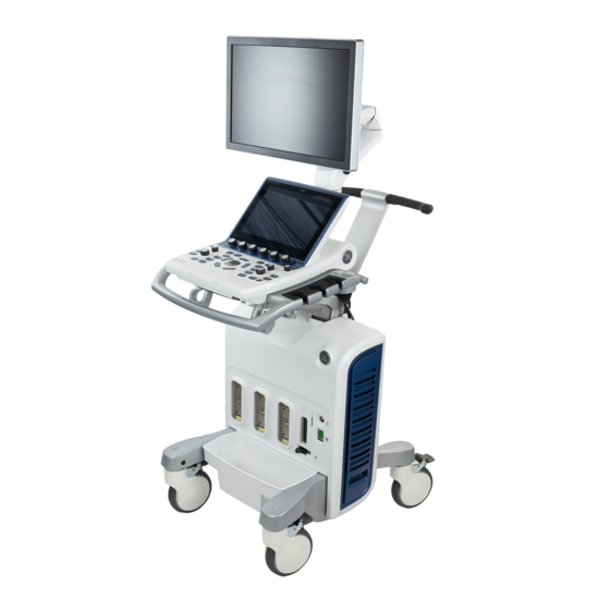
GE Vivid S70 User Manual
Hide thumbs
Also See for Vivid S70:
- Technical publication (127 pages) ,
- Quick card user manual (5 pages)

Related Manuals for GE Vivid S70


Summary of Contents for GE Vivid S70
- Page 1 Technical Publications Vivid™ S70 / Vivid S60 Version 203 0459 User Manual BC092760-1EN — English Rev. 01 Operating Documentation Copyright 2019 By General Electric Co.
- Page 2 Vivid S70 v203 and Vivid S60 v203. It applies to all revisions of the 203 software for the Vivid S70 and Vivid S60 ultrasound systems, which will hereafter be listed as Vivid S70 / S60. All information in this manual is relevant for the two systems unless otherwise specified.
- Page 3 (GE electronic Product Data Management). If you need to know the latest revision, contact your distributor, local GE Sales Representative or in the USA call the GE Ultrasound Clinical Answer Center at 1 800 682 5327 or 1 262 524 5698.
- Page 4 Regulatory Requirements Conformance Standards The GE Healthcare product families are tested to meet all applicable requirements and relevant standards per the countries in which the product will be sold. Any changes to accessories, peripheral units, or any other part of the system must be approved by the manufacturer: GE Vingmed Ultrasound AS.
-
Page 5: Certifications
São Paulo SP – CEP: 05676-120 C.N.P.J.: 00.029.372/0001-40 Número de Registro ANVISA: 80071260360 Directives The GE ultrasound product families are tested to meet all applicable requirements in relevant EU Directives and European/International standards. • Council Directive 93/42/EEC concerning MDD (Medical Devices Directive): the CE label affixed to the product testifies compliance to this Directive. -
Page 6: Class I Equipment
TYPE BF APPLIED PART providing a specified degree of protection against electric shock with particular regard to allowable LEAKAGE CURRENT. Patient leakage current Normal condition Single fault condition d.c. <10 microA <50 microA a.c. <100 microA <500 microA – Vivid S70 / S60 User Manual BC092760-1EN 01... -
Page 7: Original Documentation
Normal condition Single fault condition d.c. <10 microA <50 microA a.c. <10 microA <50 microA Original Documentation The original document was written in English. Software License Acknowledgements WindowBlinds™ OCX © Stardock ® – Vivid S70 / S60 User Manual BC092760-1EN 01... - Page 8 – Vivid S70 / S60 User Manual BC092760-1EN 01...
-
Page 9: Table Of Contents
Contact Information Contacting GE Ultrasound - - - - - - - - - - - - - - - - - - - - - - - - - - - - - - - - - 1-8 Manufacturer - - - - - - - - - - - - - - - - - - - - - - - - - - - - - - - - - - - - - - - - - 1-14 Chapter 2 —... - Page 10 Reinstalling at a new location- - - - - - - - - - - - - - - - - - - - - - - - - - - - - - 3-53 Preparing Vivid S70 / S60 for scanning - - - - - - - - - - - - - - - - - - - - - - - 3-53 –...
- Page 11 Optimizing Strain rate - - - - - - - - - - - - - - - - - - - - - - - - - - - - - - - - - - - 5-31 – Vivid S70 / S60 User Manual...
- Page 12 Continuous capture mode - - - - - - - - - - - - - - - - - - - - - - - - - - - - - - - - - 7-9 i-10 – Vivid S70 / S60 User Manual BC092760-1EN 01...
- Page 13 Approval - - - - - - - - - - - - - - - - - - - - - - - - - - - - - - - - - - - - - - - - - - - - 8-81 – i-11 Vivid S70 / S60 User Manual BC092760-1EN 01...
- Page 14 Review the images from a selected examination - - - - - - - - - - - - - - - 10-29 Review images from a selected patient record- - - - - - - - - - - - - - - - - 10-31 i-12 – Vivid S70 / S60 User Manual BC092760-1EN 01...
- Page 15 To exit the Report designer - - - - - - - - - - - - - - - - - - - - - - - - - - - - - - 11-42 – i-13 Vivid S70 / S60 User Manual BC092760-1EN 01...
- Page 16 Overview - - - - - - - - - - - - - - - - - - - - - - - - - - - - - - - - - - - - - - - - - - - 12-75 Protocol export from Vivid S70 / S60 and off-system installation of the Scan...
- Page 17 Image video out region - - - - - - - - - - - - - - - - - - - - - - - - - - - - - - - - - 14-11 – i-15 Vivid S70 / S60 User Manual BC092760-1EN 01...
- Page 18 Save TCP/IP settings - - - - - - - - - - - - - - - - - - - - - - - - - - - - - - - - - - 15-13 Index i-16 – Vivid S70 / S60 User Manual BC092760-1EN 01...
-
Page 19: Chapter 1 - Introduction
Chapter 1 Introduction The Vivid S70 / S60 is a high performance digital ultrasound imaging system with total data management. The system provides image generation in 4D (option on Vivid S70), 2D (B) Mode, Color Doppler, Power Doppler (Angio), M-Mode, Color M-Mode, PW and CW Doppler spectral, Tissue Velocity imaging, advanced Strain and Contrast applications. -
Page 20: Overview
Not all features or products described in this document may be available or cleared for sale in all markets. Please contact your local GE Healthcare representative to get the latest information. NOTE: Please note that orders are based on the individually agreed upon specifications and may not contain all features listed in this manual. -
Page 21: Documentation
The eDocumenation media includes English and all other translations. The Vivid S70 / S60 manuals are written for users who are familiar with basic ultrasound principles and techniques. They do not include sonographic training or detailed clinical procedures. -
Page 22: Indications For Use
Introduction Indications for use The Vivid S70 / S60 is a general-purpose ultrasound system, specialized for use in cardiac imaging. It is intended for use by, or under the direction of a qualified physician for ultrasound imaging and analysis of Fetal/Obstetrics; Abdominal (Including Renal and GYN);... - Page 23 Aorto-Iliac Artery Pediatric Small Organ Breast/testes/thyroid Neonatal Cephalic Adult Cephalic Cardiac (Adult and Pediatric) Cardiac (Adult) Peripheral Vascular Musculoskeletal Conventional Musculoskeletal Superficial Urology/Prostate Exam type, Means of Access: Transesophagael Transrectal Transvaginal Transurethral – Vivid S70 / S60 User Manual BC092760-1EN 01...
- Page 24 Frequency of use Daily (Typically 8 hours) Operator profile • Qualified and trained physicians or sonographers with at least basic ultrasound knowledge. • The operator must have read and understood the user manual. – Vivid S70 / S60 User Manual BC092760-1EN 01...
-
Page 25: Contraindications
Overview Contraindications The Vivid S70 / S60 is not intended for ophthalmic use or any use causing the acoustic beam to pass through the eye. Vivid S70 / S60 should be used in compliance with law. Some CAUTION jurisdictions restrict certain uses, such as gender determination. -
Page 26: Contact Information
TEL: (1) 800-682-5327 or (1) 262-524-5698 In other locations, contact your local Applications, Sales, or Service Representative. Service Questions For service in the United States, call GE CARES. TEL: (1) 800-437-1171 In other locations, contact your local Service Representative. Information... - Page 27 Nicolas Vedia 3616, piso 5 Buenos Aires BRAZIL GE Healthcare do Brasil Comércio e Serviços para Equipamentos Médico- Hospitalares Ltda Av. Magalhães de Castro, 4800, Andar 11 Conj. 111 e 112, Andar 12 Conj. 121 e 122, Torre 3 - Cidade Jardim CEP: 05676-120 - São Paulo/SP - Brasil...
- Page 28 NEW ZEALAND 8 Tangihua Street Auckland 1010 New Zealand TEL: 0800 434 325 SINGAPORE GE HEALTHCARE PTE LTD 1 Maritime Square #13-01 HarbourFront Center Singapore 099253 TEL: +65 6291 8528 1-10 – Vivid S70 / S60 User Manual BC092760-1EN 01...
- Page 29 Contact Information EUROPE and MIDDLE EAST For all other European countries not listed, please contact your local GE Healthcare distributor or the appropriate support resource listed on www.gehealthcare.com. AUSTRIA General Healthcare Austria GmbH & Co OG Technologiestr. 10, Euro Plaza Gebäude E...
- Page 30 Introduction HUNGARY GE Hungary Zrt. Ultrasound Division Akron u. 2. Budaörs 2040 Hungary TEL: (+36) 23 410 314 FAX: (+36) 23 410 390 IRELAND GE Healthcare 3050 Lake Drive, Citywest Business Campus Dublin 24 TEL: (+353) 1 4605500 ITALY GE Medical Systems Italia spa...
- Page 31 SWEDEN GE Healthcare Sverige AB FE 314, SE-182 82 Stockholm, Sweden TEL: (+46) 8 559 50010 SWITZERLAND GE Medical Systems (Schweiz) AG Europastrasse 31, 8152 Glattbrugg TEL: (+41) 1 809 92 92 FAX: (+41) 1 809 92 22 TURKEY GE Healthcare Türkiye...
-
Page 32: Manufacturer
Introduction Manufacturer GE Medical Systems, Israel Ltd. Nativ Ha’or Street no.1 3508510, Haifa, ISRAEL Tel.: (+972) 4 8519 555 Fax: (+972) 4 8519 500 1-14 – Vivid S70 / S60 User Manual BC092760-1EN 01... - Page 33 ‘Safety Precautions’ on page 2-2 ‘Owner responsibility’ on page 2-3 ‘Acoustic output’ on page 2-4 ‘Important safety considerations’ on page 2-11 ‘Device labels’ on page 2-26. – Vivid S70 / S60 User Manual BC092760-1EN 01...
-
Page 34: Safety Precautions
Indicates precautions or recommendations that should be used in the operation of the ultrasound system, specifically: • Maintaining an optimum system environment • Using this Manual • Notes to emphasize or clarify a point – Vivid S70 / S60 User Manual BC092760-1EN 01... -
Page 35: Owner Responsibility
Notice against user modification Never modify this product, including system components, software, cables, etc. User modification may cause safety hazards and degradation in system performance. All modification must be done by a GE qualified person. – Vivid S70 / S60 User Manual... -
Page 36: Acoustic Output
• TIC: Cranial bone thermal index (bone located close to the surface). Used for transcranial application. The Vivid S70 / S60 has an internal limit of 3.0 on TI for the chosen index category. Mechanical Index MI is the estimated likelihood of tissue damage due to cavitation. - Page 37 3. TI Figure 2-1. The display of MI and TI on the screen The Vivid S70 / S60 chooses the correct category based on mode of operation and chosen application, and presents the relevant TI category to the operator. It is therefore important that the operator chooses the right application.
- Page 38 Monitor TIB or TIC if bone closer than 1 cm, TIS if no bone is in the image. MI>0.7 should be used with caution in the presence of 1.0–1.5 < 120 min contrast agents. 1.5–2.0 < 60 min 2.0–2.5 < 15 min 2.5–3.0 < 4 min – Vivid S70 / S60 User Manual BC092760-1EN 01...
-
Page 39: Alara
American Institute of Ultrasound in Medicine Consensus Report on Potential Bioeffects of Diagnostic Ultrasound. The maximum possible MI and Ispta on the Vivid S70 / S60 is within the limits set in Track 3 in the FDA 510(k) guide of September 9, 2008, MI <... -
Page 40: System Controls Affecting Acoustic Output
Other parameters which optimize performance for the selected application are also set automatically, and should assist in reducing the patient exposure time. See ‘Connect and disconnect probes’ on page 3-26, for information on selecting probes and application presets. – Vivid S70 / S60 User Manual BC092760-1EN 01... - Page 41 The user can override the default settings, but care should be taken to observe the displayed MI and TI values. Power It is possible to change the power in all operating modes so that the operator can use the ALARA principle. – Vivid S70 / S60 User Manual BC092760-1EN 01...
-
Page 42: Ob Exam
Ultrasound examinations performed solely to satisfy the family's desire to know the fetal sex, to view the fetus, or to obtain a picture of the fetus should be discouraged. 2-10 – Vivid S70 / S60 User Manual BC092760-1EN 01... -
Page 43: Important Safety Considerations
Ensure that the correct patient ID is provided on all recorded data and hard copy prints. Identification errors could result in an incorrect diagnosis. – 2-11 Vivid S70 / S60 User Manual BC092760-1EN 01... - Page 44 The user should be aware of the product specifications and system accuracy and stability limitations. These limitations must be considered before making any decision based on quantitative values. If in doubt, consult the nearest GE Ultrasound Service Office. Equipment malfunction or incorrect settings can result in measurement errors or failure to detect details in the image.
- Page 45 Become familiar with the probe's use and care precautions outlined in ‘Probes’ on page 13-1. – 2-13 Vivid S70 / S60 User Manual BC092760-1EN 01...
- Page 46 ESU active and dispersive electrodes and keep the ESU cables away from the transducer or ECG cables Defibrillation Remove any sensors on the patient other than the ECG before CAUTION defibrillation. 2-14 – Vivid S70 / S60 User Manual BC092760-1EN 01...
-
Page 47: Personnel And Equipment Safety
Only approved and recommended peripherals and accessories CAUTION should be used. All peripherals and accessories must be securely mounted to the Vivid S70 / S60. Explosion hazard Never operate the equipment in the presence of flammable or WARNING explosive liquids, vapors, or gases. Malfunctions in the system or sparks generated by fan motors can electrically ignite these substances. - Page 48 Fuses blown within 36 hours of being replaced may indicate a malfunctioning electrical circuit within the system. In this event, the system must be checked by GE Ultrasound service personnel. No attempt should be made to replace the fuses with others of a higher rating.
- Page 49 However, as this system generates high frequency electrical signals, the operator should be aware of the potential hazard this could cause. Electrical safety Device classifications See ‘Classifications’ on page i-3 for more information. – 2-17 Vivid S70 / S60 User Manual BC092760-1EN 01...
- Page 50 Safety Peripheral devices Use only GE Healthcare approved internal equipment when CAUTION replacing an internal peripheral. External peripheral equipment must be in compliance with related IEC/EN standards for safety. The electrical medical systems conformance to IEC/EN60601-1 Clause 16 must be verified.
-
Page 51: Electromagnetic Compatibility (Emc)
(CISPR 11 class A). If it is used in a residential environment (for which CISPR 11 class B is normally required) this equipment might not offer adequate protection to radio-frequency communication services. The user might need – 2-19 Vivid S70 / S60 User Manual BC092760-1EN 01... - Page 52 Use of cables not properly shielded and grounded may result in the equipment causing or responding to radio frequency interference, in violation of the European Union Medical Device Directive and FCC regulations. 2-20 – Vivid S70 / S60 User Manual BC092760-1EN 01...
- Page 53 S60 other than those specified may result in increased emissions or decreased immunity of the Vivid S70 / S60. The Vivid S70 / S60 should not be used adjacent to or stacked WARNING with other equipment and that if adjacent or stacked use is necessary, the Vivid S70 / S60 should be observed to verify normal operation in the configuration in which it will be used.
- Page 54 The Vivid S70 / S60 is intended for use in the electromagnetic environment specified below. The customer or the user of the Vivid S70 / S60 should ensure that it is used in such an environment. Guidance and manufacturer’s declaration – electromagnetic emissions.
- Page 55 50 Hz or 60 Hz 50 and 60Hz typical location in a typical commercial or hospital environment. NOTE: U is the a. c. mains voltage prior to application of the test level. – 2-23 Vivid S70 / S60 User Manual BC092760-1EN 01...
- Page 56 9 V/m 5500 MHz (217 Hz PM) 9 V/m 5785 MHz (217 Hz PM) 9 V/m NOTE: Electromagnetic propagation is affected by absorption and reflection from structures, objects and people. 2-24 – Vivid S70 / S60 User Manual BC092760-1EN 01...
-
Page 57: Environmental Protection
Please follow the disassembly and part disposal procedure attached inside the system. To access to the procedure, remove the right side panel by unscrewing the two screws on the lower part. – 2-25 Vivid S70 / S60 User Manual BC092760-1EN 01... -
Page 58: Device Labels
IEC 60417-5336 connector Indicates that the product is in Rear of N/A- by compliance with all relevant European system certification Directives and under surveillance by body 0459 Notified Body 0459. 2-26 – Vivid S70 / S60 User Manual BC092760-1EN 01... - Page 59 Symbol indicating that the Instructions for Rear of ISO 7000-1641 Use are supplied in electronic form. system CAUTION - Dangerous voltage: Used to Rear of ISO 7010-W012 indicate electric shock hazards. system – 2-27 Vivid S70 / S60 User Manual BC092760-1EN 01...
- Page 60 Healthcare identification. Scan or enter the UDI information into the patient health record as required by governing laws. Device part number identifier Rear of N/A- by GE system Healthcare 2-28 – Vivid S70 / S60 User Manual BC092760-1EN 01...
- Page 61 On transport packaging. To indicate that Package the the package must be handled with labeling care. On transport packaging. To indicate that Package ISO 7000-0626 the package must be kept in dry labeling conditions. – 2-29 Vivid S70 / S60 User Manual BC092760-1EN 01...
-
Page 62: For China Only
Safety For China only 2-30 – Vivid S70 / S60 User Manual BC092760-1EN 01... - Page 63 Device labels – 2-31 Vivid S70 / S60 User Manual BC092760-1EN 01...
- Page 64 Safety 2-32 – Vivid S70 / S60 User Manual BC092760-1EN 01...
- Page 65 ‘Connect and disconnect probes’ on page 3-26 ‘The Scanning screen’ on page 3-32. ‘Control panel’ on page 3-35. ‘Main display adjustment’ on page 3-44. ‘Moving and transporting the system’ on page 3-48. – Vivid S70 / S60 User Manual BC092760-1EN 01...
-
Page 66: Site Requirements
Request training, if needed. Ensure that unauthorized personnel do not tamper with the system. Service representatives authorized by GE Ultrasound will unpack and install the system. Do not attempt to install the system alone. -
Page 67: Operating Environment
Operate the system at least 4.5 meters (15 feet) away from equipment that emits strong electromagnetic radiation. • Shield the system when operating it in the vicinity of radio broadcasting equipment, if necessary. – Vivid S70 / S60 User Manual BC092760-1EN 01... -
Page 68: Connecting The System
Prepare the System for Use Connecting the system A GE-qualified person should perform the initial system installation. Connecting the ultrasound system involves preliminary checks of the power cord, voltage level, and compliance with electrical safety requirements. Use only power supply cords, cables, and plugs provided by or designated by GE. - Page 69 Figure 3-1. The rating label location If the mains supply is not within the specified range, do not WARNING connect the system to the power source. Contact your local distributor or the appropriate support resource. – Vivid S70 / S60 User Manual BC092760-1EN 01...
- Page 70 3. Attach the power plug to the system and secure it in place by using the retaining clamp. 4. Secure the power plug to the wall outlet. 1. Ground socket 2. Retaining clamp for power plug 3. Circuit breaker Figure 3-2. Power plug – Vivid S70 / S60 User Manual BC092760-1EN 01...
- Page 71 Battery technology The lithium ion technology used in the system’s battery is significantly less hazardous to the environment than the lithium metal technology used in some other batteries (such as watch – Vivid S70 / S60 User Manual BC092760-1EN 01...
- Page 72 The % values mentioned above may fluctuate by up to +/- 3% points. View Detailed Battery Status The status of the battery charge (% charge) appears on the touch panel during Transportation mode. – Vivid S70 / S60 User Manual BC092760-1EN 01...
-
Page 73: System Overview
7. Up/down "Flex-Fit" arm 16. Front USB port 8. Probe connectors (DLP type) 17. Control panel 9. Probe-cable management tray (removable) 18. Articulated arm for display monitor Figure 3-4. Vivid S70 / S60 (front) – Vivid S70 / S60 User Manual BC092760-1EN 01... - Page 74 5. Rear I/O connectors panel 11. CD/DVD drive (option) 6. System labels 12. Doppler speakers 7. Swivel rear wheels 13. Articulated arm for display monitor Figure 3-5. Vivid S70 / S60 (rear) 3-10 – Vivid S70 / S60 User Manual BC092760-1EN 01...
-
Page 75: Removable Media
USB Flash card Archive removable media written from a Vivid S70 / S60 using CAUTION the 203 software cannot be read by a Vivid S70 / S60 using older software. NOTE: Depending on the system configuration, USB mass storage may be disabled on the system. - Page 76 4. Select the category Connectivity and select the sheet Tools (Figure 3-6). Figure 3-6. The Tools sheet 5. Select the removable media from the Media drop-down menu (CD-R, DVD-R or USB device). 3-12 – Vivid S70 / S60 User Manual BC092760-1EN 01...
- Page 77 Figure 3-7. The Eject device menu 2. Select the relevant media. Wait for the display of the Information window indicating that the device can be safely removed before removing the media. – 3-13 Vivid S70 / S60 User Manual BC092760-1EN 01...
-
Page 78: Physiological Traces
ECG and respiration traces. In M-Mode or Doppler, the traces are synchronized to that particular mode's sweep. Use only GE Healthcare accessories. CAUTION Conductive parts of electrodes and associated connectors for applied parts, including neutral electrodes should not contact other conductive parts, including earth. - Page 79 IEC (Europe, Asia, ROW) 1. RA: White 1. R: Red 2. LA: Black 2. L: Yellow 3. LL: Red 3. F: Green Figure 3-9. The cable splitter device with electrode placement conventions – 3-15 Vivid S70 / S60 User Manual BC092760-1EN 01...
- Page 80 Exception: When using an external respiratory monitor, turning off the respiratory trace on the system WILL NOT block the operation of the external monitor. Display ECG trace Figure 3-10. ECG controls 3-16 – Vivid S70 / S60 User Manual BC092760-1EN 01...
- Page 81 Display respiratory trace 1. Press the Physio tab on the Touch panel. 2. Press Respiratory. The respiratory signal appears in addition to the ECG signal. 3. The following controls can be adjusted: – 3-17 Vivid S70 / S60 User Manual BC092760-1EN 01...
- Page 82 • Lead selection: Select the one that provides a stronger signal • Horiz. Sweep: Adjusts the sweep speed. • Gain: Adjusts the trace amplitude. • Position: Moves the trace vertically. 3-18 – Vivid S70 / S60 User Manual BC092760-1EN 01...
-
Page 83: Peripheral/Accessory Connector Panel
EN 60601-1 Clause 16. If in doubt, consult the technical service department or your local representative. Do not touch the conducting parts of the USB or Ethernet cables when connecting equipment to the system. – 3-19 Vivid S70 / S60 User Manual BC092760-1EN 01... - Page 84 Digital signals only Digital monitor This is a DVI-I connector, but there is no analog signal transmission. Only digital monitors can be connected. Ethernet 1000 Base-TX Network device Ethernet IEEE 802.3 3-20 – Vivid S70 / S60 User Manual BC092760-1EN 01...
-
Page 85: Wired Footswitch (Option)
The graphic on the bottom of the main screen can be configured to show the functional assignment of the different pedals. See the example in Figure 3-13. Figure 3-13. Footswitch functional assignment – 3-21 Vivid S70 / S60 User Manual BC092760-1EN 01... - Page 86 When using the Footswitch, DO NOT hold down the footswitch CAUTION pedal. Press and release the Footswitch pedal. Pushing and holding down the pedal behaves the same way as pushing and holding down a key on the keyboard. 3-22 – Vivid S70 / S60 User Manual BC092760-1EN 01...
-
Page 87: Switching On/Off
During the boot-up process the system may require the user to enter a password to operate it. Personal IDs and associated passwords can be configured in the Vivid S70 / S60 (‘Users and Security’ on page 12-8) . If IDs and passwords have been entered and "Use Auto Logon"... -
Page 88: Switch Off The System
When AC power is resumed, the system will turn ON in less than 5 seconds (‘Using Transportation mode’ on page 3-51). 3-24 – Vivid S70 / S60 User Manual BC092760-1EN 01... - Page 89 OFF. 2. Remove the plug from the mains power socket. 3. Secure the system power cable around the cable storage hooks at the rear of the system. – 3-25 Vivid S70 / S60 User Manual BC092760-1EN 01...
-
Page 90: Connect And Disconnect Probes
5. Turn the locking handle clockwise to the full vertical position to lock in place. 6. Position the probe cable so that it is not resting on the floor. 3-26 – Vivid S70 / S60 User Manual BC092760-1EN 01... - Page 91 3. Align the connector with the probe port and carefully push into place. 4. Push the connector locking handle to the left-most position. 5. Position the probe cable so that it is not resting on the floor. – 3-27 Vivid S70 / S60 User Manual BC092760-1EN 01...
-
Page 92: Activate The Probe
When a probe is connected to the system it is automatically detected. Selecting a probe and an application 1. Press Probe on the control panel. A list of the connected probes and application presets is displayed. 3-28 – Vivid S70 / S60 User Manual BC092760-1EN 01... - Page 93 The Vivid S70 / S60 comes with a set of factory QuickApps presets for most supported probes and Application Presets. Factory QuickApps cannot be modified, but user-defined QuickApps presets can be created as needed.
-
Page 94: Deactivate The Probe
Standby mode. Disconnect the probe Probes can be disconnected at any time. It is recommended that the probe should not be active when being disconnected. 3-30 – Vivid S70 / S60 User Manual BC092760-1EN 01... -
Page 95: Intra Cardiac Ultrasound Catheters
Carefully place the probe head into the carrying case. DO NOT use excessive force or impact the probe face. Intra Cardiac Ultrasound Catheters See ‘Intracardiac Ultrasound Catheters’ on page 13-11 for information. – 3-31 Vivid S70 / S60 User Manual BC092760-1EN 01... -
Page 96: The Scanning Screen
7. Scanplane indicator (TEE probe/4D probe) 16. Current, real-time display of Heart-rate, Date 8. Greyscale/Color bar and time Figure 3-20. The scanning screen (composite) The scanning screen is divided in several areas as follows: 3-32 – Vivid S70 / S60 User Manual BC092760-1EN 01... -
Page 97: The Title Bar
Displays, if available, the current values for • Mechanical Index (MI), for the current active image • Thermal Index (TI), for the current active image • Probe temperature (for TEE probe) • Heart rate (HR) – 3-33 Vivid S70 / S60 User Manual BC092760-1EN 01... -
Page 98: Parameters Window
This window also displays zoom information, stress template, and image groups in image browser. Clipboard Displays the thumbnail images representing the acquired data during the current examination. 3-34 – Vivid S70 / S60 User Manual BC092760-1EN 01... -
Page 99: Control Panel
Control panel Control panel Control Panel overview 1. Touch panel with adjustment Softkey rotaries 10. 4D & Multi D controls (Vivid S70 only) (see page 3-42) 11. Loudspeaker volume control 2. On/Off button (see page 3-23) 12. Flex - programmable button 3. - Page 100 NOTE: When preparing the system to be moved, pull the left handle and bring the control panel to a center position. Swivel it slightly till a locking click is heard. 3-36 – Vivid S70 / S60 User Manual BC092760-1EN 01...
-
Page 101: Trackball Area
(see page 12-17). Figure 3-22. The Trackball area The current active state of the trackball is displayed on the bottom of the display (Figure 3-23). Figure 3-23. Trackball assignment graphical display – 3-37 Vivid S70 / S60 User Manual BC092760-1EN 01... -
Page 102: Touch Panel
3. Main body with touch controls. 4. Rotary/Push buttons with mode/function specific controls. 5. Swipe the screen to change page. 6. Extended On/Off switch: Show/Hide advanced controls. Figure 3-24. Touch panel 3-38 – Vivid S70 / S60 User Manual BC092760-1EN 01... - Page 103 • Bodymark: Access bodymarks. • Review: Review images in selected examination. • Text: Access the annotation function. • Report: Access the report function. • QuickApps: Access QuickApps function. Figure 3-26. Additional shortcuts – 3-39 Vivid S70 / S60 User Manual BC092760-1EN 01...
- Page 104 Variable button: Control with variable adjustment Dual button: Combines two controls that exclude each other mutually (e.g. toggling between Dual and Quad screen display) 3-40 – Vivid S70 / S60 User Manual BC092760-1EN 01...
- Page 105 Extended On: Display all available controls. Extended Off: Display only the main controls. Page indicator: Swipe laterally anywhere on the Touch panel to toggle display of page 1 and 2. – 3-41 Vivid S70 / S60 User Manual BC092760-1EN 01...
-
Page 106: The Alphanumeric Keyboard (Option)
Additionally, a physical alphanumeric keyboard can be optionally installed on the system. In this case the keyboard is situated under the control panel, in a drawer which can open and close. 3-42 – Vivid S70 / S60 User Manual BC092760-1EN 01... - Page 107 Control panel Figure 3-29. Extendable physical alphanumeric keyboard (optional) – 3-43 Vivid S70 / S60 User Manual BC092760-1EN 01...
-
Page 108: Main Display Adjustment
(Figure 3-30). Figure 3-30. Positioning the main display NOTE: When flipping up the display from the flip down state, you can grab the upper corner of the display. 3-44 – Vivid S70 / S60 User Manual BC092760-1EN 01... -
Page 109: Image Adjustment
Activate the main menu on the touch panel. • Tap the LCD setup tab. The touch-panel will display several screen adjustments controls (Figure 3-32). These screen controls allow the user to optimize the screen settings. – 3-45 Vivid S70 / S60 User Manual BC092760-1EN 01... - Page 110 The touch panel setup screen contains a rotary controller to adjust the brightness of touch panel. It is also possible to let the automatic light-sensor take over and control the brightness constantly adjusting it to the ambient light. 3-46 – Vivid S70 / S60 User Manual BC092760-1EN 01...
- Page 111 Main display adjustment Test pattern When adjusting an external display or any peripheral hard-copy device, you may turn this function ON to generate a screen-calibration pattern to assist in exact callibration. – 3-47 Vivid S70 / S60 User Manual BC092760-1EN 01...
-
Page 112: Moving And Transporting The System
8. If intending to travel over bumpy surface or if more visibility is required during transportation, fold the main display forward to a horizontal position (‘Main display adjustment’ on page 3-44). 3-48 – Vivid S70 / S60 User Manual BC092760-1EN 01... - Page 113 Once all cables and cords are wrapped and secure out of the lower portion of the system, not extending beyond sides of system, you are ready for transport. – 3-49 Vivid S70 / S60 User Manual BC092760-1EN 01...
- Page 114 Avoid ramps that are steeper than 10 degrees. • Utilize additional care and personnel when moving on a steep incline (>5 degrees). • Ensure the main display arm and Control panel are in locked position. 3-50 – Vivid S70 / S60 User Manual BC092760-1EN 01...
-
Page 115: Using Transportation Mode
Check the Battery indicator. When the battery's charge is less than 20% the system switches to Standby mode and the touch screen turns off after the power cable is disconnected from power. – 3-51 Vivid S70 / S60 User Manual BC092760-1EN 01... -
Page 116: Transporting The System
5. Ensure that the system is secured inside the vehicle. Secure it with straps to prevent movement while in transit. 6. Drive cautiously to prevent vibration damage. 3-52 – Vivid S70 / S60 User Manual BC092760-1EN 01... -
Page 117: Reinstalling At A New Location
C or above 35 Hours Preparing Vivid S70 / S60 for scanning 1. Lock front Wheel brakes 2. Un-Wrap the AC power cord and plug into power source. 3. Lift the main display to the fully open position. Secure the Monitor at full upright position. - Page 118 Avoid hanging cables beyond sides of the system. When system is moved, these cables may be caught in door-knobs or other medical equipment and apply severe forces that may break probe cables or connectors. 3-54 – Vivid S70 / S60 User Manual BC092760-1EN 01...
- Page 119 Chapter 4 Start an Examination ‘Starting an examination’ on page 4-2 ‘Cineloop’ on page 4-6. ‘Zoom’ on page 4-9 ‘Annotations’ on page 4-10 – Vivid S70 / S60 User Manual BC092760-1EN 01...
-
Page 120: Starting An Examination
(Figure 4-3 on page 4-5), depending on the system configuration (see page 12-65). If the system is configured to display the Patient info and exam screen, follow the steps below: – Vivid S70 / S60 User Manual BC092760-1EN 01... -
Page 121: Selecting An Existing Patient Record
Archive: The examination is finished and the Archive screen is displayed. Any search criteria previously entered are remembered. • End Exam: The examination is finished and the Archive screen is displayed ready for a new search. – Vivid S70 / S60 User Manual BC092760-1EN 01... - Page 122 2. Change user. accordingly (ascending/descending). 3. Advanced search filters 5. Display either patient or examination list. The Archive screen may be slightly different depending on the Dataflow selected Figure 4-2. The Archive screen – Vivid S70 / S60 User Manual BC092760-1EN 01...
- Page 123 4. List of examinations 2. Examination information 5. List of available information to display on screen 3. Clipboard with images for the selected examination Figure 4-3. The Patient info and exam screen – Vivid S70 / S60 User Manual BC092760-1EN 01...
-
Page 124: Cineloop
Touch panel to cover one or more heart cycles. Cineloop overview 1. Left marker (cineloop start) 3. Right marker (cineloop end) 2. Current frame 4. Cine speed Figure 4-4. Cineloop display – Vivid S70 / S60 User Manual BC092760-1EN 01... -
Page 125: Using Cineloop
The speed factor (%) is displayed on the right side of the ECG. To view a cineloop frame by frame 1. In freeze, use the trackball or adjust Frame to scroll through the cineloop frame by frame. – Vivid S70 / S60 User Manual BC092760-1EN 01... - Page 126 • Images are single cycle loops where the first image frame corresponds to the R wave. Storage of a cineloop See ‘Storing a cineloop’ on page 10-8. – Vivid S70 / S60 User Manual BC092760-1EN 01...
-
Page 127: Zoom
2. Use the trackball to position the zoom area over the desired portion of the image. 3. Increase size as desired by turning the Zoom knob clockwise. 4. Press Zoom one more time to turn off the HR zoom. – Vivid S70 / S60 User Manual BC092760-1EN 01... -
Page 128: To Insert An Annotation
To select annotations from another application, press the button under the label Library... and select the desired application library. 2. On the Touch panel, press the pre-defined text to insert. The word is displayed on the screen. 4-10 – Vivid S70 / S60 User Manual BC092760-1EN 01... - Page 129 Text 2). This function enables the user to show/hide different annotations on the same image. 1. Press Text 1 on the Touch panel. The Text 1 layer is displayed. Enter an annotation. – 4-11 Vivid S70 / S60 User Manual BC092760-1EN 01...
-
Page 130: Editing Annotations
Shift + Tab: Moves the text cursor backward by word. • Enter: Moves the cursor to the next line. • Backspace: Deletes backward. • Delete: Deletes forward. • Insert: Toggles the text entry state from overwrite to insert mode. 4-12 – Vivid S70 / S60 User Manual BC092760-1EN 01... -
Page 131: To Erase Text Annotations
• Press Move pattern. • Move the bodymark to a new location with the trackball. • Press Move pattern to anchor the bodymark to the new location. 6. Press Select. – 4-13 Vivid S70 / S60 User Manual BC092760-1EN 01... -
Page 132: Annotation And Bodymark Configuration
1. Press Utility/Config on the Touch panel and log on as administrator if required. 2. Select the Meas/Text category and Text or Bodymark subgroup. The corresponding screen is displayed (Figure 4-6, Figure 4-7). Figure 4-6. The Text sheet 4-14 – Vivid S70 / S60 User Manual BC092760-1EN 01... - Page 133 Touch panel (e.g. pressing the toggling annotation Left will insert the text “Left” and toggle the – 4-15 Vivid S70 / S60 User Manual BC092760-1EN 01...
- Page 134 If Body Mark is selected, the default bodymark will appear automatically at “Home” position. See bottom left in Figure 4-8. The default bodymark is the first in the list, see Figure 4-9. Figure 4-8. Home position 4-16 – Vivid S70 / S60 User Manual BC092760-1EN 01...
- Page 135 Bodymark or text mode after Probe Mark position is adjusted. In Freeze, “Depth” control can be used to rotate Probe Mark when Bodymark is active. The system will stay in Bodymark or text mode when Active side is changed. – 4-17 Vivid S70 / S60 User Manual BC092760-1EN 01...
- Page 136 Reset reloads the factory default setting. Bodymark size Select Normal or Large bodymark size. Default is Large. Copy Bodymark to active side Copies bodymark to active side in dual or quad screen. 4-18 – Vivid S70 / S60 User Manual BC092760-1EN 01...
- Page 137 ‘Tissue Tracking’ on page 5-26 ‘Strain rate’ on page 5-29 ‘Strain’ on page 5-32 ‘Tissue Synchronization Imaging (TSI)’ on page 5-35 ‘Contrast Imaging’ on page 5-39 ‘Additional scanning features’ on page 5-46 – Vivid S70 / S60 User Manual BC092760-1EN 01...
- Page 138 Image Optimization ‘Image controls’ on page 5-49 ‘Scan Assist Pro’ on page 5-59 – Vivid S70 / S60 User Manual BC092760-1EN 01...
-
Page 139: 2D-Mode
2D-Mode 2D-Mode 2D-Mode overview 1. Focus marker 2. Probe orientation marker 3. Parameter window Figure 5-1. The 2D screen (cardiac) – Vivid S70 / S60 User Manual BC092760-1EN 01... - Page 140 Image Optimization Figure 5-2. 2D Touch panel (4D probe Live) page 1 and 2 – Vivid S70 / S60 User Manual BC092760-1EN 01...
-
Page 141: Using 2D-Mode
• Use the Gain and TGC controls to optimize the overall image. Gain increases or decreases the amount of echo information displayed. TGC compensates for depth-related attenuation in the image. – Vivid S70 / S60 User Manual BC092760-1EN 01... - Page 142 A scan plane indicator is displayed showing the angle position of the scan plane. Always use the minimum power required to obtain acceptable WARNING images in accordance with applicable guidelines and policies. – Vivid S70 / S60 User Manual BC092760-1EN 01...
-
Page 143: M-Mode
It is not to be used for measurements or analysis. This is not an absolute value, but simply a reference number. Users performing studies using standardized protocols may find this sweep speed information useful for reading studies from other institutions. Figure 5-3. The M-Mode screen (composite) – Vivid S70 / S60 User Manual BC092760-1EN 01... - Page 144 Image Optimization Figure 5-4. M-Mode Touch panel page 1 and 2 – Vivid S70 / S60 User Manual BC092760-1EN 01...
-
Page 145: Using M-Mode
3. Press Trackball to allow free rotation of the solid full-length cursor line throughout the 2D image (trackball assigned function: Angle). 4. Rotate the solid cursor line to the desired direction. – Vivid S70 / S60 User Manual BC092760-1EN 01... - Page 146 7. On the last point, press Select twice to terminate the curve. NOTE: To edit the time motion curve, select a point, move it to a new position and press Select. 5-10 – Vivid S70 / S60 User Manual BC092760-1EN 01...
-
Page 147: Optimizing M-Mode
Use the Focus Pos control to center the focal point around the region of interest. • Adjust Power to obtain an acceptable image using the lowest setting possible. NOTE: The Power setting affects all other operating modes. – 5-11 Vivid S70 / S60 User Manual BC092760-1EN 01... -
Page 148: Color Mode
Image Optimization Color Mode Color 2D Mode overview 1. Probe orientation marker 2. Color bar 3. Color sector marker 4. Parameter window Figure 5-5. The Color Mode screen 5-12 – Vivid S70 / S60 User Manual BC092760-1EN 01... - Page 149 Color Mode Figure 5-6. Color 2D Touch panel page 1 and 2 – 5-13 Vivid S70 / S60 User Manual BC092760-1EN 01...
-
Page 150: Color M-Mode Overview
Color M-Mode overview 1. Time motion cursors (M-Mode, AMM and Curved AMM) 2. Color bar 3. Flow sector marker 4. Time scale 5. Parameter window Figure 5-7. The Color M-Mode screen (composite) 5-14 – Vivid S70 / S60 User Manual BC092760-1EN 01... - Page 151 Color Mode Figure 5-8. Color M-Mode Touch panel page 1 and 2 (Color controls) – 5-15 Vivid S70 / S60 User Manual BC092760-1EN 01...
-
Page 152: Using Color Mode
Refer to ‘Generating a new preset’ on page 12-90 about creating presets. • Adjust the Active mode gain to set the gain in the color flow area. • Adjust Scale to the highest setting that provides adequate flow detection. 5-16 – Vivid S70 / S60 User Manual BC092760-1EN 01... - Page 153 PRF directly. • Adjust Power to obtain an acceptable image using the lowest setting possible. NOTE: The Power setting affects all other operating modes. – 5-17 Vivid S70 / S60 User Manual BC092760-1EN 01...
- Page 154 An increase of the lateral averaging will reduce noise, but this will also reduce the lateral resolution. Use all noise reduction controls with care. Excessive CAUTION application may obscure low level diagnostic information. 5-18 – Vivid S70 / S60 User Manual BC092760-1EN 01...
-
Page 155: Pw And Cw Doppler
Users performing studies using standardized protocols may find this sweep speed information useful for reading studies from other institutions. Figure 5-9. The PW/CW Doppler Mode screen – 5-19 Vivid S70 / S60 User Manual BC092760-1EN 01... - Page 156 Image Optimization Figure 5-10. The PW Doppler Touch panels page 1and 2 5-20 – Vivid S70 / S60 User Manual BC092760-1EN 01...
-
Page 157: Using Pw/Cw Doppler Modes
Adjustment of the Sample volume may affect the PRF (Nyquist limit) settings. • Adjust the Compress setting to balance the effect of stronger and weaker echoes and obtain the desired intensity display. – 5-21 Vivid S70 / S60 User Manual BC092760-1EN 01... - Page 158 It will avoid the display of a folded spectrum and stretch the spectrum vertically as large as possible. ASO optimization is not continuous but performed instantaneously each time Auto is pressed. 5-22 – Vivid S70 / S60 User Manual BC092760-1EN 01...
-
Page 159: Tissue Velocity Imaging (Tvi)
The information is stored in a combined format with grayscale imaging during one or several cardiac cycles with high temporal resolution. 1. TVI color bar 2. Parameter window Figure 5-11. The TVI Mode screen – 5-23 Vivid S70 / S60 User Manual BC092760-1EN 01... - Page 160 Image Optimization Figure 5-12. TVI Touch panel page 1 and 2 5-24 – Vivid S70 / S60 User Manual BC092760-1EN 01...
-
Page 161: Using Tvi
However, from this window the beam cannot be aligned with the muscle for all the parts of the ventricle. NOTE: PW will be optimized for Tissue Velocities when activated from inside TVI. – 5-25 Vivid S70 / S60 User Manual BC092760-1EN 01... -
Page 162: Tissue Tracking
1. Tissue Tracking color bar 2. Track start and track end markers 3. Tracking start and end from detected QRS 4. Parameter window Figure 5-13. The Tissue Tracking Mode screen 5-26 – Vivid S70 / S60 User Manual BC092760-1EN 01... - Page 163 Tissue Tracking Figure 5-14. The Tissue Tracking Touch panel page 1 and 2 – 5-27 Vivid S70 / S60 User Manual BC092760-1EN 01...
-
Page 164: Using Tissue Tracking
Tissue Tracking provides velocity information only in the beam direction. The apical view typically provides the best window since the beams are then approximately aligned to the longitudinal direction of the myocardium (except near the apex). 5-28 – Vivid S70 / S60 User Manual BC092760-1EN 01... -
Page 165: Strain Rate
Strain rate is calculated as the spatial gradient of velocity data. 1. Strain rate color bar 2. Strain length and Strain rate reject 3. Parameter window Figure 5-15. The Strain rate mode screen – 5-29 Vivid S70 / S60 User Manual BC092760-1EN 01... - Page 166 Image Optimization Figure 5-16. The Strain rate Touch panel page 1 and 2 5-30 – Vivid S70 / S60 User Manual BC092760-1EN 01...
-
Page 167: Using Strain Rate
Strain rate. If set too high, the maximum Strain rate color is never reached. • Low strain rates may be masked out with a green color using the SRI Reject control. – 5-31 Vivid S70 / S60 User Manual BC092760-1EN 01... -
Page 168: Strain
1. Strain color bar 2. Strain start and end markers 3. Strain start and end from detected QRS and Strain sample size 4. Parameter window Figure 5-17. The Strain mode screen 5-32 – Vivid S70 / S60 User Manual BC092760-1EN 01... - Page 169 Strain Figure 5-18. The Strain Touch panel page 1 and 2 – 5-33 Vivid S70 / S60 User Manual BC092760-1EN 01...
-
Page 170: Using Strain
(except near the apex). • Low strain values may be masked out with a different color using the SI Reject control. 5-34 – Vivid S70 / S60 User Manual BC092760-1EN 01... -
Page 171: Tissue Synchronization Imaging (Tsi)
1. TSI start/end and TSI Cut-off 2. TSI start and end markers 3. QRS marker 4. TSI color bar 5. Parameter window Figure 5-19. The TSI mode screen – 5-35 Vivid S70 / S60 User Manual BC092760-1EN 01... - Page 172 Image Optimization Figure 5-20. The TSI Touch panel page 1 and 2 5-36 – Vivid S70 / S60 User Manual BC092760-1EN 01...
-
Page 173: Using Tsi
TSI start: AVO, 60, 80, 100, 120 ms, or Manual control • TSI end: AVC, AVC - 200 ms, AVC - 150 ms, AVC - 100 ms, AVC - 50 ms, AVC, AVC + 50 ms, AVC + 100 ms, – 5-37 Vivid S70 / S60 User Manual BC092760-1EN 01... - Page 174 2. In the Measure category, select the sheet Advanced. 3. In the Application specific parameters section adjust TSI start and TSI end parameters by selecting a new value from the combo menu displayed upon selection. 5-38 – Vivid S70 / S60 User Manual BC092760-1EN 01...
-
Page 175: Contrast Imaging
CAUTION ultrasound contrast agents have been observed in the diagnostic range of Mechanical Index (MI) values. See the specific package insert for the contrast agent being used for further details. – 5-39 Vivid S70 / S60 User Manual BC092760-1EN 01... - Page 176 The LV Contrast application may help to identify LV thrombus and evaluate wall motion. 5-40 – Vivid S70 / S60 User Manual BC092760-1EN 01...
- Page 177 Contrast Imaging 1. Parameter window Figure 5-21. The LV Contrast acquisition screen – 5-41 Vivid S70 / S60 User Manual BC092760-1EN 01...
- Page 178 5. To continuously monitor the view orientation while acquiring contrast data, press Simultan. to activate a side-by-side view of tissue and contrast visualization. Always read and follow carefully the manufacturer instructions WARNING on the contrast agent label. 5-42 – Vivid S70 / S60 User Manual BC092760-1EN 01...
- Page 179 Too high Power setting will destroy the contrast agent in the LV CAUTION cavity. – 5-43 Vivid S70 / S60 User Manual BC092760-1EN 01...
-
Page 180: Quantification
• Arbitrary Anatomical M-Mode (Curved and Straight): M-Mode applied to intensity data calculates and color-codes tissue along a path drawn by the operator vs. time. 5-44 – Vivid S70 / S60 User Manual BC092760-1EN 01... -
Page 181: Contrast Echocardiography Box
For further information on quantification, see ‘Quantitative Analysis’ on page 9-1. Contrast Echocardiography Box Contrast Echocardiography Box: the European Society of Cardiology provides useful information on contrast echocardiography on the Internet here: https:// www.escardio.org/Guidelines-&-Education/Practice-tools/ EACVI-toolboxes/Contrast-Echo/ Contrast-Echocardiography-Box – 5-45 Vivid S70 / S60 User Manual BC092760-1EN 01... -
Page 182: Additional Scanning Features
5. To complete the scan, press Freeze. 6. Adjust LogiqView rotate to rotate the acquisition. NOTE: The quality of the resulting image is somewhat user-dependent and requires some additional skill and practice to develop proper technique. 5-46 – Vivid S70 / S60 User Manual BC092760-1EN 01... -
Page 183: Compound
Therefore, have the scan direction opposite to that of flow direction. Switch the way you hold the probe, with the probe – 5-47 Vivid S70 / S60 User Manual BC092760-1EN 01... -
Page 184: Blood Flow Imaging
BFI is available with linear and curved linear probes. Using Blood Flow Imaging 1. While in Color flow, press BFI. 2. Adjust Flow speckle. Increased Flow speckle enhances hemodynamics. 5-48 – Vivid S70 / S60 User Manual BC092760-1EN 01... -
Page 185: Image Controls
Width/2D width 2D, CF, TVI, TT, SRI, Controls the size or angular width of the 2D image. A smaller angle generally SI, TSI produces an image with a higher frame rate. – 5-49 Vivid S70 / S60 User Manual BC092760-1EN 01... - Page 186 Performs a temporal processing which reduces random noise without affecting the motion of significant tissue structures. An index number is displayed on the control to indicate the relative DDP level. 5-50 – Vivid S70 / S60 User Manual BC092760-1EN 01...
- Page 187 Extra care must be taken to select the optimal Speckle reduction level. A decrease of UD Clarity creates a smoother image, though keeping boundaries sharp. An increase of UD Clarity creates a crisper image. – 5-51 Vivid S70 / S60 User Manual BC092760-1EN 01...
- Page 188 When power is reduced, it reduces the signal-to-noise ratio, so that the image may become noisier. Horizontal sweep M-Mode, Doppler Adjusts the horizontal refresh rate of the M-Mode or Doppler area of the display. Horizontal sweep is available in live and cine replay. 5-52 – Vivid S70 / S60 User Manual BC092760-1EN 01...
- Page 189 Controls the amount of variance data added to a color display. Variance enables computer-aided detection of turbulent flow (e.g. jets or regurgitation). Variance is available in live and cine replay. – 5-53 Vivid S70 / S60 User Manual BC092760-1EN 01...
- Page 190 Enables toggling between high and low Pulse Repetition Frequency (PRF). When the Doppler PRF is raised beyond a certain limit, more than one Doppler gate is displayed on the screen. 5-54 – Vivid S70 / S60 User Manual BC092760-1EN 01...
- Page 191 TVI visible Turns TVI display on/off. Q Analysis TVI, TT, SRI, SI, TSI Starts the Quantitative analysis application. (In Freeze) – 5-55 Vivid S70 / S60 User Manual BC092760-1EN 01...
- Page 192 Controls the time after strain start when the strain calculation should end. The strain end time is displayed on the screen and is represented on the ECG by a red marker. 5-56 – Vivid S70 / S60 User Manual BC092760-1EN 01...
- Page 193 Enables intermittent imaging based on the ECG. Persistence Vascular Contrast Enables the adjustment of color images, so that the current frame retains some color information from previous frames, in order to minimize noise. – 5-57 Vivid S70 / S60 User Manual BC092760-1EN 01...
- Page 194 Cineloop storage adjustment. Press the rotary to toggle between Num Cycle and SI, TSI Time span. • Num Cycle: adjust number of heart cycles to store. • Time span: adjust the storage length in seconds. 5-58 – Vivid S70 / S60 User Manual BC092760-1EN 01...
-
Page 195: Scan Assist Pro
5. This column indicates the action to move the Protocol to the next step. 6. Navigation: Stop, Pause/Continue the Protocol. Figure 5-23. Scan Assist Pro window – 5-59 Vivid S70 / S60 User Manual BC092760-1EN 01... - Page 196 2. Protocols available for the selected category. 3. Stop, Pause/Continue and restart Protocol. 4. Change current step. Change position and size of the Scan Assist Pro window. Figure 5-24. Scan Assist Pro Touch panel 5-60 – Vivid S70 / S60 User Manual BC092760-1EN 01...
-
Page 197: Setting Up Scan Assist Pro
Refer to ‘Scan Assist Pro Creator’ on page 12-75 for more information on how to create a Protocol. 2. Press Utility/Config on the Touch panel and log on if required. 3. Select Imaging/Scan Assist Pro. – 5-61 Vivid S70 / S60 User Manual BC092760-1EN 01... - Page 198 5. In the Source field, select the media that the Protocol is stored on. 6. Highlight the Protocol(s) to be imported. If a folder is highlighted, all Protocols in the folder are selected. 5-62 – Vivid S70 / S60 User Manual BC092760-1EN 01...
-
Page 199: Using Scan Assist Pro
Scan Assist Pro 7. Select Import. The Protocol(s) are stored to the Vivid S70 / S60. NOTE: If the Protocol(s) already exist a confirmation dialog is displayed asking the user to confirm the replacement of the existing Protocol(s). Add the imported Protocol to the Protocol selection The imported Protocol(s) must be added to the Protocol selection to be available on the Scan Assist Pro Touch panel. - Page 200 7. To skip a step or move to a certain step, press the Up/Down arrow key on the keyboard or select the step you want to move to using the trackball. 5-64 – Vivid S70 / S60 User Manual BC092760-1EN 01...
- Page 201 Chapter 6 4D and Multi-plane Modes ‘4D-Mode’ on page 6-2 ‘Multi-plane mode’ on page 6-35 ‘FlexiViews’ on page 6-46 – Vivid S70 / S60 User Manual BC092760-1EN 01...
-
Page 202: Mode
4D and Multi-plane Modes 4D-Mode 4D mode is an option available on Vivid S70. Real-time, single beat 4D imaging The 4D transesophageal probe on Vivid S70 enables real-time, single beat 4D tissue and color imaging. The volume data is displayed in real-time with volume rendering techniques for visualization of valves and structures. -
Page 203: 4D-Mode
The brown line with X indicates the cropping applied to the Volume rendering. 4. Orientation window: displays a three-dimensional scene with acquisition sector and 2D image positions. 5. Trackball functions 6. Footswitch functions (option) Figure 6-1. The 4D-Mode screen (Volume rendering) – Vivid S70 / S60 User Manual BC092760-1EN 01... - Page 204 4D and Multi-plane Modes Figure 6-2. 4D Touch panel (4D probe Live) page 1 and 2 – Vivid S70 / S60 User Manual BC092760-1EN 01...
- Page 205 Select the “4D Marker” tab on the touchpanel when in 4D mode. (Figure 6-4). Select one of the pre-defined markers, or click “User Defined…” if you would like to define your own text. The cursor changes to the “cross” symbol: – Vivid S70 / S60 User Manual BC092760-1EN 01...
- Page 206 4D markers. The selected size will apply to the 4D Marker which will be placed next. It does not influence the size of the markers which are already placed. – Vivid S70 / S60 User Manual BC092760-1EN 01...
- Page 207 The color of the laser lines corresponds to the color coding used for the 2D images. 5. Press Store to store the acquisition. – Vivid S70 / S60 User Manual BC092760-1EN 01...
- Page 208 4D acquisition preset on the Touch panel: Medium (medium size sector with top-down view) or Large (large sector more suited for acquisition of the complete LV). – Vivid S70 / S60 User Manual BC092760-1EN 01...
- Page 209 The 2D image locations are shown as overlaying red or color coded lines following the surface in the volume rendering. The color of the laser lines corresponds to the color coding used for the 2D images. – Vivid S70 / S60 User Manual BC092760-1EN 01...
- Page 210 (e.g image quality, presence and visibility of all walls, stitching artifacts when using real time multi beat acquisition). Apical views are displayed on the left side for orientation purpose. 6-10 – Vivid S70 / S60 User Manual BC092760-1EN 01...
- Page 211 2. Lower slice Figure 6-6. Multi Slice screen NOTE: Press Layout on the touch panel or use the dedicated buttons on the Touch panel to get the following display alternatives. – 6-11 Vivid S70 / S60 User Manual BC092760-1EN 01...
- Page 212 The cursor is changed to . Drag to rotate the slices backward/forward and sideways, to align the slices with the anatomical structure. 6-12 – Vivid S70 / S60 User Manual BC092760-1EN 01...
- Page 213 Pos/Size and Width/Tilt. • Press Select to toggle the trackball function between ROI width (Width) and ROI tilt (Tilt). The Width and Tilt controls affect the ROI in the elevation plane only. – 6-13 Vivid S70 / S60 User Manual BC092760-1EN 01...
-
Page 214: 4D Color Flow Mode
4. Orientation window: displays a three-dimensional scene with acquisition sector and 2D image positions. 5. Trackball functions 6. Footswitch functions (option) Figure 6-8. 4D Color Flow screen (Volume rendering) 6-14 – Vivid S70 / S60 User Manual BC092760-1EN 01... - Page 215 4D-Mode Figure 6-9. The 4D Color Flow mode Touch panel – 6-15 Vivid S70 / S60 User Manual BC092760-1EN 01...
- Page 216 (e.g. valves) compared to the time lag between the tissue and the color volume acquisitions. Tissue data should only be used as guidance for the localization of the flow data. 6-16 – Vivid S70 / S60 User Manual BC092760-1EN 01...
- Page 217 8. Press Freeze. In 2D Freeze, look for stitching artifacts in the color flow data in both the volume rendering and the elevation plane in the lower left window of the screen. – 6-17 Vivid S70 / S60 User Manual BC092760-1EN 01...
-
Page 218: Flexi-Slice
To start the Flexi-Slice mode press Flexi-slice while in 4D or 4D Color Flow mode. Flexi-Slice mode screen 1. Volume rendering 2. Cut-plane 1 (yellow) 3. Cut-plane 2 (white) 4. Cut-plane 3 (green) Figure 6-10. The 4D screen (Flexi-Slice mode) 6-18 – Vivid S70 / S60 User Manual BC092760-1EN 01... - Page 219 1. Volume rendering 2. Cut-plane 1 (yellow) 3. Cut-plane 2 (white) 4. Cut-plane 3 (green) Figure 6-11. 4D Color Flow screen (Flexi-Slice mode) Figure 6-12. The Flexi-Slice mode control panel – 6-19 Vivid S70 / S60 User Manual BC092760-1EN 01...
-
Page 220: Basic Operations
Control Panel”) and translated (independently only) using the Trackballl: 1. Press Yellow, White or Green on the control panel to select the Reference plane. The volume rendering is updated accordingly. 6-20 – Vivid S70 / S60 User Manual BC092760-1EN 01... - Page 221 4D Views requires slice alignment before standard views can be selected. 4D Views is available in Freeze and replay. 1. Press 4D Views on the control panel. The Slice alignment screen is displayed. – 6-21 Vivid S70 / S60 User Manual BC092760-1EN 01...
- Page 222 2 chamber slice around the main axis. • Place the cursor at one of the extremities of the Mid-esophageal (ME) long axis slice intersection line (green) in the short axis view. The cursor is changed to 6-22 – Vivid S70 / S60 User Manual BC092760-1EN 01...
- Page 223 Pressing Delete on the Touch panel will remove any previously approved alignments and exit the Slice alignment function. 3. Select the desired standard view on the Touch panel. Figure 6-15. The 4D Views Touch panel – 6-23 Vivid S70 / S60 User Manual BC092760-1EN 01...
- Page 224 If desired repeat the procedure to create a new cropped view. 5. Press 2-Click Crop to go back to the Volume rendering screen. 6. To remove 2-click crop, press Clear on the touch panel. 6-24 – Vivid S70 / S60 User Manual BC092760-1EN 01...
- Page 225 3. Crop plane intersection. The X symbols indicate the cropped side. Figure 6-16. Crop plane 1 in the azimuth plane 1. Press Crop tool on the Touch panel (page 2). – 6-25 Vivid S70 / S60 User Manual BC092760-1EN 01...
- Page 226 Pressing down a button containing a check mark will make the corresponding existing crop plane active. Pressing a button without a check mark will introduce a new crop plane, and make it active. 7. To remove crop planes: 6-26 – Vivid S70 / S60 User Manual BC092760-1EN 01...
- Page 227 4D mode. Make sure to use the correct glasses. Figure 6-17. 3D anaglyph glasses NOTE: Not all users may be able to perceive depth using stereoscopic display techniques. – 6-27 Vivid S70 / S60 User Manual BC092760-1EN 01...
-
Page 228: 4D-Mode Controls
Depending on the situation: • Toggles between 4D Color Flow Prepare mode and 4D Color Flow acquisition. • Toggles between 4D/4D Color Flow Zoom mode and 4D/4D Color Zoom prepare mode. 6-28 – Vivid S70 / S60 User Manual BC092760-1EN 01... - Page 229 • Scroll: scrolls through a cineloop (in Freeze). Angle 4D, 4D Color Sets the cut-planes and crop planes to pre-defined positions. Clear 4D, 4D Color Sets the cut-planes and crop planes to the default position. – 6-29 Vivid S70 / S60 User Manual BC092760-1EN 01...
- Page 230 Adjusts the number of heart beats the multi beat acquisition is based on. View Crop 4D, 4D Color Crop mode where the view plane and the crop plane always coincide. 6-30 – Vivid S70 / S60 User Manual BC092760-1EN 01...
- Page 231 Very bright colors are almost white, independent of the depth. Depth Illumination map: this color map creates shadows to improve the perception of depth. Rotate the Light source rotary on the Touch panel to adjust the light angle. – 6-31 Vivid S70 / S60 User Manual BC092760-1EN 01...
- Page 232 Abs: rotation of the volume about the probe axis. The volume rendering can be tilted. Rel: Rotation of the volume about x and y axis. Left/right movement rotates about the y-axis, up/down about the x-axis. 6-32 – Vivid S70 / S60 User Manual BC092760-1EN 01...
- Page 233 Pressing Biplane on the Touch panel enters the biplane acquisition mode, keeping the cut-planes shown in the 4D mode, but with higher resolution and frame rate. – 6-33 Vivid S70 / S60 User Manual BC092760-1EN 01...
- Page 234 • Depth Mode on: when clicking in the volume rendering the reference plane is moved inside the volume to the corresponding depth. • Depth Mode off: the reference plane is kept at the current depth. 6-34 – Vivid S70 / S60 User Manual BC092760-1EN 01...
-
Page 235: Multi-Plane Mode
Multi-plane mode Multi-plane mode Multi-plane mode is an option available on Vivid S70. Bi-plane mode screen 1. Scan plane 1 (yellow): default reference scan plane. This scan plane can be rotated together with scan plane 2, but it cannot be tilted. - Page 236 4D and Multi-plane Modes Figure 6-19. The Bi-plane mode Touch panel (page 1 and 2) 6-36 – Vivid S70 / S60 User Manual BC092760-1EN 01...
-
Page 237: Tri-Plane Mode Screen
4. Orientation window: displays all the scan planes in a projection. 5. Navigator: displays rotation angle values for the scan planes 1 (A) if rotated, 2 (A1) and 3 (A2). 6. Trackball functions Figure 6-20. The Tri-plane imaging mode screen – 6-37 Vivid S70 / S60 User Manual BC092760-1EN 01... - Page 238 4D and Multi-plane Modes Figure 6-21. The Tri-plane mode Touch panel (page 1 and 2) 6-38 – Vivid S70 / S60 User Manual BC092760-1EN 01...
-
Page 239: Using Multi-Plane Mode
Pressing Bi-plane on the Touch panel enters the Bi-plane acquisition mode, keeping the cut-planes shown in the 4D mode, but with higher resolution and frame rate. – 6-39 Vivid S70 / S60 User Manual BC092760-1EN 01... - Page 240 3. Press Bi-plane on the Touch panel (or Multi D on the Control panel) to start high resolution and high frame rate bi-plane acquisition. 4. Press Store to save the acquisition. 6-40 – Vivid S70 / S60 User Manual BC092760-1EN 01...
-
Page 241: Basic Operations
Angle 1 and Angle 2 rotary buttons. 3. In Bi-plane mode only, press V-planes to rotate scan plane 2, so that it has the same angle as scan plane 1. The – 6-41 Vivid S70 / S60 User Manual BC092760-1EN 01... - Page 242 Pos and use the trackball to freely move the zoomed area within the scan plane. 2. Press Select to toggle the trackball function to Size and use the trackball to adjust the size of the zoomed area (2D mode only). 6-42 – Vivid S70 / S60 User Manual BC092760-1EN 01...
-
Page 243: Multi-Plane Mode Controls
• In Tri-plane mode, toggles the display between the default Tri-plane quad screen, a quad screen with enlarged Geometric model and a single screen showing the selected scan plane. – 6-43 Vivid S70 / S60 User Manual BC092760-1EN 01... - Page 244 Toggles between Bi-plane and Tri-plane mode. Reference Plane Toggles the reference plane between the scan planes. The reference plane may also be selected using the trackball when the Pointer trackball tool selected. 6-44 – Vivid S70 / S60 User Manual BC092760-1EN 01...
- Page 245 ROI, press 4D to acquire 4D data for the defined ROI (see page 6-13). Right Invert In Transesophageal Bi-plane mode Live only: mirrors the image on the right hand side. – 6-45 Vivid S70 / S60 User Manual BC092760-1EN 01...
- Page 246 4D Gain and Multibeat. Vivid S70 with 4D option come with a set of factory defined views. Users can create their own defined views as needed. Storing FlexiViews while in zoom is limited to 4D modes and 4D Zoom Prepare.
- Page 247 Displayed images may not accurately reflect the user-defined name of the selected FlexiView. The Configure button opens the configuration screen which allows showing/hiding FlexiViews, and sorting the Enabled FlexiViews as described in Figure 6-26. – 6-47 Vivid S70 / S60 User Manual BC092760-1EN 01...
- Page 248 2. The arrows allow ordering the FlexiViews according to user preferences. The Enabled FlexiViews are divided in columns of 4 elements each. Empty cells may be added to customize the layout of the buttons within the FlexiViews tab. Figure 6-26. FlexiViews configuration 6-48 – Vivid S70 / S60 User Manual BC092760-1EN 01...
- Page 249 ‘Selection of a stress test protocol template’ on page 7-3 ‘Image acquisition’ on page 7-4 ‘Stress Echo analysis’ on page 7-16 ‘Quantitative TVI Stress echo analysis’ on page 7-20 ‘Editing/creating a Stress Echo protocol template’ on page 7-26 – Vivid S70 / S60 User Manual BC092760-1EN 01...
-
Page 250: Introduction
(TVI), see page 7-20. A stress echo examination consists of three steps: • Selection of a stress test protocol template (page 7-3) • Image acquisition (page 7-4) • Stress analysis (page 7-16) – Vivid S70 / S60 User Manual BC092760-1EN 01... -
Page 251: Selection Of A Stress Test Protocol Template
Turn freeze off to initiate scanning. NOTE: To create or edit a template see page 7-26. 1. Level selection 2. Projection selection 3. Current acquisition 4. Group of views Figure 7-1. The Protocol screen – Vivid S70 / S60 User Manual BC092760-1EN 01... -
Page 252: Image Acquisition
1. Current view, level and timers 2. Template matrix view and level 3. Current view (Green cell) Figure 7-2. The stress mode acquisition screen – Vivid S70 / S60 User Manual BC092760-1EN 01... -
Page 253: Starting Acquisition
The template used can be configured so that analysis is automatically started, displaying the first protocol group. The wall segment scoring diagrams for each view is displayed in the – Vivid S70 / S60 User Manual BC092760-1EN 01... - Page 254 A fixed protocol is provided for scanning, based on the selected template. The system automatically highlights the next view to be acquired in the template matrix, as images are stored. However, the order of scanning may be changed manually as follows. – Vivid S70 / S60 User Manual BC092760-1EN 01...
- Page 255 After storage the system automatically highlights the next available view to be acquired. – Vivid S70 / S60 User Manual BC092760-1EN 01...
- Page 256 T2 starts when entering live scanning on the second stress level Press Protocol T2 on the Touch panel to stop/start the T2 timer. Timers restart always at zero. The display of T1 and T2 is user-configurable (see page 7-26). – Vivid S70 / S60 User Manual BC092760-1EN 01...
-
Page 257: Continuous Capture Mode
PAUSE: live scanning without storing • CAPTURE: live scanning with storing to buffer • The percentage of the buffer that is filled • The buffer filling progression showed by a filling gauge – Vivid S70 / S60 User Manual BC092760-1EN 01... - Page 258 The system enters Freeze mode automatically once the buffer is full. The captured recording is stored on disk and the captured loops are displayed in the Continuous capture selection screen (see below). 7-10 – Vivid S70 / S60 User Manual BC092760-1EN 01...
- Page 259 13. Press Done if you are finished selecting or want to do the selection later. Press Select later if you want to return to the scanning screen. If there are more rows in the protocol template, the – 7-11 Vivid S70 / S60 User Manual BC092760-1EN 01...
- Page 260 8. Perform Analysis and scoring (see page 7-16). Postponed image assignment The assignment of the cineloops to the views can be done on a later stage on a stored Continuous capture acquisition. 7-12 – Vivid S70 / S60 User Manual BC092760-1EN 01...
- Page 261 3. Press Store to start capture. Assigning and storing the loops The cineloops captured in the buffer are assigned to the stress protocol views and stored from the Continuous capture selection screen (see Figure 7-5). – 7-13 Vivid S70 / S60 User Manual BC092760-1EN 01...
- Page 262 4. Buffer bar: to browse through the acquisition, select an area in the buffer bar to display the corresponding page or select the first, last, previous or next page buttons. Figure 7-5. The Continuous capture selection screen 7-14 – Vivid S70 / S60 User Manual BC092760-1EN 01...
- Page 263 1. Assigned loop 2. Highlighted loop 3. Already assigned view 4. Highlighted views Figure 7-6. Loop assignment in Continuous capture – 7-15 Vivid S70 / S60 User Manual BC092760-1EN 01...
-
Page 264: Stress Echo Analysis
Pressing Analyze (while no images are selected in Protocol screen) will automatically open the first group of images in Analyze screen. 3. Press Select to open images in the Analyze screen (see page 7-18). 7-16 – Vivid S70 / S60 User Manual BC092760-1EN 01... - Page 265 4. Repeat steps 2 and 3 to select other images. 5. Press Analyze to open images in the Analyze screen (see page 7-18). NOTE: Alternative: Double click on the last selected image to open images. – 7-17 Vivid S70 / S60 User Manual BC092760-1EN 01...
-
Page 266: Wall Motion Scoring
NOTE: The number of segments (WMS segment model), the range of scoring values (WMS scoring legend) and the initial scoring 7-18 – Vivid S70 / S60 User Manual BC092760-1EN 01... - Page 267 5. Rotate Review page to display next group of images. 6. Repeat steps 1 through 3 to score relevant segments on the new loops. 1. Selected segment 2. Selected score 1. Scored segment Figure 7-9. Segment scoring – 7-19 Vivid S70 / S60 User Manual BC092760-1EN 01...
-
Page 268: Quantitative Tvi Stress Echo Analysis
The velocity cutoff values are based on placing the sample volume at center of each cardiac segment at start of systole, the left ventricle myocardial segments are defined by the American 7-20 – Vivid S70 / S60 User Manual BC092760-1EN 01... - Page 269 • ‘Quantitative analysis’ on page 7-25, enables further quantitative analysis based on multiple tissue velocity traces. The quantitative analysis is described in Chapter ‘Quantitative Analysis’ on page 9-1. – 7-21 Vivid S70 / S60 User Manual BC092760-1EN 01...
-
Page 270: Accessing Qtvi Stress Analysis Tools
QTVI Stress can be used only in conjunction with wall motion CAUTION scoring analysis, as a guiding tool. When activating QTVI Stress, the measurement applies only to the currently highlighted segment for the current level and projection view. 7-22 – Vivid S70 / S60 User Manual BC092760-1EN 01... - Page 271 Result window (Figure 7-11). 4. Use Segment Select to analyze the other segments in the peak view, Select another scoring bullet in the diagram in one of the peak views. – 7-23 Vivid S70 / S60 User Manual BC092760-1EN 01...
- Page 272 (see reference 1 on page 7-25). The result is highlighted by a color-coding of the thresholds lines, the 7-24 – Vivid S70 / S60 User Manual BC092760-1EN 01...
-
Page 273: Tissue Tracking
1. Application of Tissue Doppler to Interpretation of Dubotamine Echocardiography and Comparison With Quantitative Coronary Angiography. Cain P, Baglin T, Case C, Spicer D, Short L. and Marwick T H. Am. J. Cardiol. 2001; 87: 525-531 – 7-25 Vivid S70 / S60 User Manual BC092760-1EN 01... -
Page 274: Editing/Creating A Stress Echo Protocol Template
1. Press Stress on the Touch panel to enter the stress echo mode. 2. Press Template. The Template menu is displayed. 3. Select Template Editor. The Template editor screen is displayed (see Figure 7-12). 7-26 – Vivid S70 / S60 User Manual BC092760-1EN 01... -
Page 275: Editing/Creating A Template
Determine the required number of projections and levels you need and select the most appropriate foundation template. The selected template is displayed in the Protocol template preview field, showing the levels and projections and their labels. – 7-27 Vivid S70 / S60 User Manual BC092760-1EN 01... - Page 276 If you want to use Smart stress in Continuous capture, you need to use the arrow buttons to indicate to the system when you are switching views. 7-28 – Vivid S70 / S60 User Manual BC092760-1EN 01...
- Page 277 A dialogue box is displayed asking the user to enter a name for the new group. 3. Enter the group name. 4. Press OK. The new group is displayed in the Pre-defined group field. – 7-29 Vivid S70 / S60 User Manual BC092760-1EN 01...
- Page 278 Deleting a group 1. In the Pre-defined group field, select the group to delete. 2. Press Delete group. The group is removed from the list in the Pre-defined group field. 7-30 – Vivid S70 / S60 User Manual BC092760-1EN 01...
- Page 279 ‘4D Auto MVQ’ on page 8-67 ‘4D Auto AVQ’ on page 8-76 ‘Advanced vascular measurements and analysis’ on page 8-82 ‘OB measurements’ on page 8-87 ‘Measurement result table’ on page 8-93 ‘Worksheet’ on page 8-94. – Vivid S70 / S60 User Manual BC092760-1EN 01...
- Page 280 Measurements and Analysis ‘Measurement accuracy’ on page 8-97 – Vivid S70 / S60 User Manual BC092760-1EN 01...
-
Page 281: Introduction
Measurements and calculations are displayed in the Measurements result table (see page 8-93). Assigned measurements and calculations are automatically gathered into a Worksheet and used to populate the patient report. – Vivid S70 / S60 User Manual BC092760-1EN 01... -
Page 282: General Recommendations About Measurements
(Figure 8-1). The Value column contains calculated values based on the input parameter values in the Value column. – Vivid S70 / S60 User Manual BC092760-1EN 01... - Page 283 The Measurement result window always displays values from the m1, m2... columns. It is therefore recommended to consult the worksheet (see page 8-94) to get an overview of measured and calculated parameters. – Vivid S70 / S60 User Manual BC092760-1EN 01...
-
Page 284: Assign And Measure Modality
This can also be done from the Touch panel. To perform measurements from a study: 1. Select the study (folder) in the Measurement menu. NOTE: This can also be done from the Touch panel. – Vivid S70 / S60 User Manual BC092760-1EN 01... - Page 285 If the folder is configured with auto-sequence measurement (see page 12-20), the next measurement in the study is pre-selected. To skip a pre-selected measurement, select another measurement. Completed measurements are marked with a check mark. – Vivid S70 / S60 User Manual BC092760-1EN 01...
-
Page 286: Measure And Assign Modality
Make sure to follow the current medical practices when placing the specific points on the image. NOTE: The system supports up to 15 separate measurements per M&A session. When exceeding this limit the measurements – Vivid S70 / S60 User Manual BC092760-1EN 01... -
Page 287: Measurements On Volume Renderings
6-25) with a short distance between the crop planes. Be aware that the Gain adjustment (2D and 4D Gain) may impact the display of the anatomical structures to measure. – Vivid S70 / S60 User Manual BC092760-1EN 01... -
Page 288: Measurements On Protocol Images
Measurement results associated with a stress level will not be CAUTION updated if the image is moved to another stress level at a later time. Images should be correctly placed in the protocol before performing measurements. 8-10 – Vivid S70 / S60 User Manual BC092760-1EN 01... -
Page 289: Advanced Cardiac Measurements And Analysis
The event timing measurement (ms) is displayed in the Measurement result table. When an event timing measurement is performed, the QRS markers are displayed on the ECG trace and correct QRS – 8-11 Vivid S70 / S60 User Manual BC092760-1EN 01... -
Page 290: Tsi Measurements
To judge the quality of your data at the measuring point in the 2D image the TSI trace may be used (see ‘TSI trace’ on page 8-14). See also the Caution text on page 8-17. 8-12 – Vivid S70 / S60 User Manual BC092760-1EN 01... - Page 291 • Basal seg. max diff.: difference between the maximum and minimum time to peak measurements in the six basal segments. Requires at least four of the six basal segment measurements. – 8-13 Vivid S70 / S60 User Manual BC092760-1EN 01...
- Page 292 The TSI Time to peak measurement can be verified and eventually manually changed from the TSI trace. 1. Double click on the measurement point. The ROI and the corresponding TSI curve are displayed (see Figure 8-7). 8-14 – Vivid S70 / S60 User Manual BC092760-1EN 01...
- Page 293 3. If required, select a new peak location in the trace. 4. Click in the acquisition window to exit the TSI trace. 1. TSI ROI 2. TSI trace 3. TSI Time to peak marker Figure 8-7. TSI trace – 8-15 Vivid S70 / S60 User Manual BC092760-1EN 01...
- Page 294 Q Analysis and compare the result with a manual Time to peak measurement. To access the corresponding measurement tool in Q Analysis you may have to press Active mode to display the relevant Measurement menu. 8-16 – Vivid S70 / S60 User Manual BC092760-1EN 01...
- Page 295 TSI Time to peak measurements may return the time to a different peak than what a manual method would do. Typically in these situations, the TSI image will show a wide range of colors over a small spatial region. – 8-17 Vivid S70 / S60 User Manual BC092760-1EN 01...
-
Page 296: Automated Function Imaging
Global Strain for the whole LV, standard deviation of the segmental Time To Peak Strain and the Aortic Valve Closure time used in the analysis are stored to the worksheet. 8-18 – Vivid S70 / S60 User Manual BC092760-1EN 01... - Page 297 Advanced cardiac measurements and analysis Figure 8-9. AFI workflow – 8-19 Vivid S70 / S60 User Manual BC092760-1EN 01...
- Page 298 The tool will launch and start up in the Select View stage. (see Figure 8-11). Annotate the view by clicking one of the view labeling buttons (A4CH, A2CH, APLAX). 8-20 – Vivid S70 / S60 User Manual BC092760-1EN 01...
- Page 299 APLAX view. This allows manual adjustment of the Aortic Valve Closure (AVC) event timing that is used in the calculation of the longitudinal systolic strain in all apical views. – 8-21 Vivid S70 / S60 User Manual BC092760-1EN 01...
- Page 300 2. An automatic ROI is generated when entering the Define ROI stage, see Figure 8-10. The ROI may be edited by clicking and dragging on the endocardial and epicardial contours. See ‘ROI adjustment’ on page 8-25 for more information. 8-22 – Vivid S70 / S60 User Manual BC092760-1EN 01...
- Page 301 The tracking for each segment must be visually controlled and validated as described below. Figure 8-13. Results stage in Quad layout – 8-23 Vivid S70 / S60 User Manual BC092760-1EN 01...
- Page 302 2D image. When in Quad layout it may be helpful to turn off the color overlay by clicking Color button. It can also be helpful to reduce playback speed by 8-24 – Vivid S70 / S60 User Manual BC092760-1EN 01...
- Page 303 (highlighted in red on mouse hovering). Epicardial editing edits the epicardial part only (Figure 8-14, lower part). In the upper right of the screen there is a pictogram indicating the core features of a good APLAX ROI. – 8-25 Vivid S70 / S60 User Manual BC092760-1EN 01...
- Page 304 Sometimes the automatic ROI may fail to capture the correct ROI. In this case, a 3-Point ROI alternative is provided. NOTE: The 3-Point ROI is the standard ROI method for TEE data and Pediatric exams. 8-26 – Vivid S70 / S60 User Manual BC092760-1EN 01...
- Page 305 The timing when auto processing of the ROI will start is configurable (from Config). NOTE: The Yo-yo function is turned on to help find correct location for the points. Figure 8-15. AFI auto processing configuration – 8-27 Vivid S70 / S60 User Manual BC092760-1EN 01...
- Page 306 Tip: Make sure to follow the recommendations when placing the three points (see below). Base Correct Wrong 1. Correct position of the base points. 2. The ROI extends into the aortic tract. 8-28 – Vivid S70 / S60 User Manual BC092760-1EN 01...
- Page 307 The ROI is extending beyond the epicardium. 1. Correct position of the Apex point. 2. The upper right border of the ROI is way too much into the chamber cavity. – 8-29 Vivid S70 / S60 User Manual BC092760-1EN 01...
- Page 308 Timing information may be crucial to accurate diagnosis. The most important event timing is the aortic valve closure (AVC), since it is part of the definition of the end systolic strain parameter. 8-30 – Vivid S70 / S60 User Manual BC092760-1EN 01...
- Page 309 After completed tracking, and for APLAX completed AVC timing adjustment, the system displays the Quad screen layout for tracking validation (see page 8-24) and inspection of results for this view. – 8-31 Vivid S70 / S60 User Manual BC092760-1EN 01...
- Page 310 M-mode has a parametric overlay indicating peak strain values. NOTE: Rejected segments will not have texture overlay. NOTE: The Segmental result ROI, Strain traces and Curved anatomic M-mode are using color codes to link the different segments. 8-32 – Vivid S70 / S60 User Manual BC092760-1EN 01...
- Page 311 AutoEF measurements generated in the AFI tool will not be considered as validated by the user. Therefore, they will not appear in the result screen nor be transferred to Worksheet. – 8-33 Vivid S70 / S60 User Manual BC092760-1EN 01...
- Page 312 The Bull’s eye can be configured to display either 18 or 17 segments using either the AFI or the ASE standard (from Config). Consult the Vivid S70 / S60 Reference Manual for more information regarding Bull’s Eye segmentation formats. If reprocessing a file with a different Bull’s Eye standard, the CAUTION segmental values will change.
- Page 313 PSD as the color scheme uses green color to indicate normal contraction with a peak around AVC, blue color to indicate early contraction, and yellow to red color to indicate late contraction. – 8-35 Vivid S70 / S60 User Manual BC092760-1EN 01...
- Page 314 If all three views have been analyzed, the tool will go to the Bull’s eye only layout and prompt the operator whether the results should be stored. If Yes is selected, measurements 8-36 – Vivid S70 / S60 User Manual BC092760-1EN 01...
- Page 315 • All results shown (curves, colors and values) are based on drift compensated values. Any strain drifting is linearly compensated throughout the cycle. If the drift compensation – 8-37 Vivid S70 / S60 User Manual BC092760-1EN 01...
- Page 316 Measurements based on endocardial and myocardial analysis CAUTION are not comparable. • Endocardial deformation is assessed by performing analysis of the endocardial part of the ROI trace. Measurements 8-38 – Vivid S70 / S60 User Manual BC092760-1EN 01...
- Page 317 ROI stage. "Auto" AVC or Event timing will be used by default. It will still be possible for the user to re-visit the AVC Selection stage to edit the chosen AVC. – 8-39 Vivid S70 / S60 User Manual BC092760-1EN 01...
- Page 318 Fraction for the whole LV. All values are stored to the worksheet when approved. Acquisition 1. Create an exam, connect the ECG device and make sure to obtain a stable ECG trace. 8-40 – Vivid S70 / S60 User Manual BC092760-1EN 01...
- Page 319 Pay attention to the left/right orientation of the image by comparing the LV wall names with a visual inspection of the image. If the image orientation is wrong: • Go back to the Select view stage. – 8-41 Vivid S70 / S60 User Manual BC092760-1EN 01...
- Page 320 If the tracking results are visually correct, you may press Approve and Exit to exit the tool and store the values to the worksheet, so they can be used in a report. 8-42 – Vivid S70 / S60 User Manual BC092760-1EN 01...
- Page 321 The shape of the endocardial border trace is updated accordingly. In the upper right of the screen there is a pictogram indicating the core features of a good APLAX AutoEF ROI. – 8-43 Vivid S70 / S60 User Manual BC092760-1EN 01...
- Page 322 NOTE: The timing when auto processing of the ROI will start is configurable (from Config). NOTE: The Yo-yo function is turned on to help find correct location for the points. 8-44 – Vivid S70 / S60 User Manual BC092760-1EN 01...
- Page 323 Launch AutoEF. The tool will proceed to the Results stage. You may choose to reprocess the view already analyzed or to complete the analysis adding the missing view to the analysis. – 8-45 Vivid S70 / S60 User Manual BC092760-1EN 01...
-
Page 324: Cardiac Autodoppler
Automated Trace Detection 1. Select Auto to initiate automatic trace detection. 2. The generated trace is created as seen below and average measurement values are displayed. 8-46 – Vivid S70 / S60 User Manual BC092760-1EN 01... - Page 325 4. When hovering over a cycle, the cycle can be rejected or exclusively kept by clicking the corresponding symbol to reject or keep. Press the Recalc button to restore rejected cycles. – 8-47 Vivid S70 / S60 User Manual BC092760-1EN 01...
- Page 326 5. Press Store when satisfied with all the displayed cycles. Results 6. After Store is pressed, the results for each cycle are split into separate measurements and displayed as seen below. 8-48 – Vivid S70 / S60 User Manual BC092760-1EN 01...
-
Page 327: Pediatric Z-Score Measurements
Z-score button to display a dialog where it is possible to select what publication to use. It is also possible to select/deselect individual Z-score parameters by enabling/disabling them as described under ‘Configuration of the Measurement menu’ on page 12-21. – 8-49 Vivid S70 / S60 User Manual BC092760-1EN 01... -
Page 328: 4D/Multi-Plane Lv
Measurements and Analysis 4D/Multi-plane LV 4D/multi-plane LV analysis tools Depending on the data set, the following 4D/multi-plane LV analysis tools are available on the Vivid S70: Data set Tool Tri-plane Tri-plane TSI 4D Automated LV Quantification page 8-50 Tri-plane LV Volume... - Page 329 The tool must not be used on other chambers than the human adult left ventricle. NOTE: When the 4D Auto LVQ tool is used on Vivid S70 / S60, it is possible to store the traces, bullseye, 3D model, and measurements shown as part of the user interface to images files by pressing the Store button.
- Page 330 Figure 8-25. 4D Auto LVQ measurement selection The Measurement menu is displayed with the Alignment tool selected (Figure 8-25). Figure 8-26. Measurement menu The main screen displays three apical and a short axis views. 8-52 – Vivid S70 / S60 User Manual BC092760-1EN 01...
- Page 331 Auto alignment is not available with transesophageal acquisitions, only manual alignment as described in ‘Alignment – Transesophageal acquisition’ on page 6-22. See page 6-21 for more information on Slice alignment. – 8-53 Vivid S70 / S60 User Manual BC092760-1EN 01...
- Page 332 Go To ED on the Touch panel. The end diastolic frame is displayed. To edit the contours, see ‘Contour adjustment’ on page 8-57. To reset the contours and start over, press Reset. The following measurements are available: 8-54 – Vivid S70 / S60 User Manual BC092760-1EN 01...
- Page 333 If the Auto or Manual contour detection method was used to define the EDV contour (see step 3 on page 8-54) the same method is used for the ESV contour detection. – 8-55 Vivid S70 / S60 User Manual BC092760-1EN 01...
- Page 334 To reset the contours and start over, press Reset. The following measurements are available: • End diastolic volume • End systolic volume • Ejection Fraction • Sphericity Index • Cardiac Output • Stroke Volume • Heart Rate 8-56 – Vivid S70 / S60 User Manual BC092760-1EN 01...
- Page 335 3. To delete an attracting point, double click on the point or press Undo. a. Original contour b. Modified contour 1. Original attracting points 2. Added attracting point Figure 8-29. Contour adjustment – 8-57 Vivid S70 / S60 User Manual BC092760-1EN 01...
- Page 336 The measurement results are updated. The following measurements are available: • End diastolic volume • End systolic volume • Ejection Fraction • Sphericity Index • Cardiac Output • Stroke Volume • Heart Rate 8-58 – Vivid S70 / S60 User Manual BC092760-1EN 01...
- Page 337 Calculation formula and measurement accuracy Refer to the Reference manual for calculation formula information and ‘Measurement accuracy’ on page 8-97 for measurement accuracy information. – 8-59 Vivid S70 / S60 User Manual BC092760-1EN 01...
-
Page 338: Manual Left Ventricular Volume Measurements
The Measurement screen is displayed with the Ejection fraction tool selected (see Figure 8-31). The end diastolic frame of the current cardiac cycle is displayed and the cursor is moved to the reference scan plane. 8-60 – Vivid S70 / S60 User Manual BC092760-1EN 01... - Page 339 When the last end-diastolic contour is drawn, an end-systolic frame is automatically displayed. The system automatically enters scroll mode. Using the trackball, ensure that the correct end-systolic frame is displayed. – 8-61 Vivid S70 / S60 User Manual BC092760-1EN 01...
- Page 340 5. In the Measurement menu select Volume and Tri-plane. The Measurement screen is displayed with the Ejection fraction tool selected. 6. Follow the procedure described in ‘Tri-plane acquisition’ on page 8-60 from step 7. 8-62 – Vivid S70 / S60 User Manual BC092760-1EN 01...
- Page 341 The Measurement menu is displayed. 6. In the Measurement menu select Volume and Bi-plane. The Trace tool for the Left ventricular end-diastolic volume for the Apical 4 chamber view is selected (see Figure 8-32). – 8-63 Vivid S70 / S60 User Manual BC092760-1EN 01...
- Page 342 13. Repeat steps 7 to 10 to perform the end-systolic measurements in the Apical 4 chamber and 2 chamber views. The Ejection fraction (Bi-plane) and the end-diastolic and end-systolic left ventricular volumes are calculated. 8-64 – Vivid S70 / S60 User Manual BC092760-1EN 01...
-
Page 343: Tsi Surface Model
6. In scan plane 1 (yellow), place the cursor to the start point for the sampling path starting in the myocardium. 7. Move the cursor following the myocardium and press Select to place new points. – 8-65 Vivid S70 / S60 User Manual BC092760-1EN 01... - Page 344 1. Place the cursor over a control point. 2. Press Select twice (double-click) and move the control point to a new position using the trackball. 3. Press Select to place the control point to its new position. 8-66 – Vivid S70 / S60 User Manual BC092760-1EN 01...
-
Page 345: 4D Auto Mvq
4D TEE images of the Mitral Valve (MV). Upon completion of the segmentation the tool will provide metrics for the MV annulus and leaflet during systole. The 4D Auto MVQ tool is only on the Vivid S70 with 4D option available when 4D is enabled. Requirements 4D Auto MVQ is available on 4D trans-esophageal echocardiographic (TEE) tissue data sets in replay mode only. -
Page 346: Starting 4D Auto Mvq
2. Press Measure. 3. Select Valve/4D Auto MVQ (Figure 8-34) Figure 8-34. Selecting the 4D Auto MVQ tool. The Measurement menu is displayed with the Align Views tool selected (Figure 8-35). 8-68 – Vivid S70 / S60 User Manual BC092760-1EN 01... -
Page 347: Align Views
The alignment of the data must be performed in order to identify standard views: Mitral-Commissural view (MC, top left), Antero-Posterior Long Axis view (APLAX, top right) and short axis 3D view aligned with MV annulus (Figure 8-36). – 8-69 Vivid S70 / S60 User Manual BC092760-1EN 01... -
Page 348: Set Landmarks
(MA1 and MA2); on APLAX view mark the Posterior annulus hinge (P), Anterior annulus hinge (A), Coaptation (Coap), and Right Sinus Aortic Annulus (Ao) points. 3. When last landmark is placed segmentation is automatically launched. 8-70 – Vivid S70 / S60 User Manual BC092760-1EN 01... - Page 349 4D Auto MVQ Figure 8-37. Set Landmark stage – 8-71 Vivid S70 / S60 User Manual BC092760-1EN 01...
-
Page 350: Review
4. In commissure layout the user can modify commissure points. On left 3D image the user can place mouse cursor on one of the commissures while loop is playing and click. 8-72 – Vivid S70 / S60 User Manual BC092760-1EN 01... -
Page 351: Results
Dynamic Layout, while in other layouts a 3D annotation showing the measured entity is displayed in the 3D interactive view. Figure 8-39. The Results screen, showing MV measurements. – 8-73 Vivid S70 / S60 User Manual BC092760-1EN 01... - Page 352 Measurements and Analysis Figure 8-40. The Results screen, showing Dynamic Layout Figure 8-41. The Results screen, showing Measurement layout 8-74 – Vivid S70 / S60 User Manual BC092760-1EN 01...
-
Page 353: Approval
Worksheet tab of the measurement table. The measurements are transferred to the Worksheet. To exit without approving, press Cancel. NOTE: Measurements that are not approved will not be saved. – 8-75 Vivid S70 / S60 User Manual BC092760-1EN 01... -
Page 354: 4D Auto Avq
LVOT and aortic root. Upon completion of the segmentation the tool will provide metrics for the aortic annulus diameter and area. The 4D Auto AVQ tool is only available on Vivid S70. Requirements The 4D Auto AVQ tool is available on 4D trans-esophageal echocardiographic (TEE) tissue data sets in replay mode only. -
Page 355: Starting The 4D Auto Avq Tool
The main screen displays two long axis slices (90 degree rotated with respect to each other), a short axis view at the annulus plane and a free view (Figure 8-44). – 8-77 Vivid S70 / S60 User Manual BC092760-1EN 01... -
Page 356: Slice Alignment
(defined as 15% of the R-R interval). The segmentation is shown as curves where the 3D LVOT boundary intersects the 2D slices as well as a surface model. 8-78 – Vivid S70 / S60 User Manual BC092760-1EN 01... - Page 357 • To delete an attracting point, double click on the point. 1. Long axis view 2. Short axis view 3. Interactive view 4. 3D surface model Figure 8-45. LVOT segmentation – 8-79 Vivid S70 / S60 User Manual BC092760-1EN 01...
-
Page 358: Measurements
SAX plane lateral position (distance from aortic valve). Two layouts are available by use of the Layout button on the Vivid S70 / S60 control panel and the Layout button in the user interface on EchoPAC Software Only (see Figure 8-46). -
Page 359: Approval
1. Press Approve and exit to store the measurements shown in the Measurement result table. The measurements are transferred to the Worksheet. To exit without approving, press Cancel. NOTE: Measurements that are not approved will not be saved. – 8-81 Vivid S70 / S60 User Manual BC092760-1EN 01... -
Page 360: Advanced Vascular Measurements And Analysis
IMT measurement is generally more accurate than the anterior IMT measurement. The following parameters are calculated: • Average IMT • Maximum IMT • Minimum IMT • Standard deviation of IMT measurements • Number of successful IMT measurements 8-82 – Vivid S70 / S60 User Manual BC092760-1EN 01... - Page 361 4. Press Measure. 5. Select the appropriate IMT measurement. If measuring the IMT of the posterior wall of the right common carotid select Rt and CCA IMT Post (Figure 8-48). – 8-83 Vivid S70 / S60 User Manual BC092760-1EN 01...
- Page 362 If the Intima and Media layers are not within the search region, the contour is not drawn. Select (double click) and move the anchored points closer to the Intima layer. 8-84 – Vivid S70 / S60 User Manual BC092760-1EN 01...
-
Page 363: Vascular Autodoppler
Press Transfer to approve the measurements again. Vascular AutoDoppler Vascular AutoDoppler enables the Vivid S70 / S60 to detect and identify a cardiac cycle, and allows measurements and calculations during live timeline imaging while the image is frozen or in cine. - Page 364 There is an inherent risk that these algorithms may sometimes give suboptimal or incorrect results. Verify the correctness of the displayed points and traces before approving them. 8-86 – Vivid S70 / S60 User Manual BC092760-1EN 01...
-
Page 365: Ob Measurements
For multi-gestational patients you can show curves for all fetuses and compare the growth on the graphs. The Vivid S70 / S60 provides the following two basic types of graphs: •... - Page 366 Using the current ultrasound measurement data, where the fetus is on the growth curve From the OB graphs screen, the user can enter relevant information in the Fetus position and Placenta fields. 8-88 – Vivid S70 / S60 User Manual BC092760-1EN 01...
- Page 367 An editing window is displayed. 2. Enter a new value and select OK. The GA (LMP) label is changed to GA(GA) showing the new value entered. This information is also updated in the – 8-89 Vivid S70 / S60 User Manual BC092760-1EN 01...
- Page 368 3. Press Single to display single graph screen again. Figure 8-51. Fetal growth curve graph: quad screen 8-90 – Vivid S70 / S60 User Manual BC092760-1EN 01...
- Page 369 3. Press Plot both. The system automatically finds the data from previous ultrasound exams, and displays it on the graph with the present data. Figure 8-52. Fetal trending graph – 8-91 Vivid S70 / S60 User Manual BC092760-1EN 01...
- Page 370 The blue dotted vertical line shows the ultrasound age using the current measurements. • The yellow x shows the ultrasound age for each measurement. • The green rectangle shows the normal age range for the measurement. 8-92 – Vivid S70 / S60 User Manual BC092760-1EN 01...
-
Page 371: Measurement Result Table
Select to anchor the table. Deleting measurements 1. Select the measurement to delete in the Measurement result table. 2. Select Delete measurement in the context menu. – 8-93 Vivid S70 / S60 User Manual BC092760-1EN 01... -
Page 372: Overview
1. Measurement type 4. Measured / calculated values 2. Measurement parameter 5. Value type: Averaging, Max, Min or Last 3. Value calculated according to the value type selected. Figure 8-54. Worksheet screen 8-94 – Vivid S70 / S60 User Manual BC092760-1EN 01... -
Page 373: Using The Worksheet
1. Place the cursor over the measurement to exclude. 2. Press Update Menu. 3. Select Exclude value/Include value from the context menu. – 8-95 Vivid S70 / S60 User Manual BC092760-1EN 01... - Page 374 Delete all to delete all values from the Worksheet. To change a measurement value 1. Select the measurement to change. 2. Enter a new value. NOTE: Changed measurements are marked with an asterisk (*). 8-96 – Vivid S70 / S60 User Manual BC092760-1EN 01...
-
Page 375: Measurement Accuracy
Image measurement The accuracy in lateral direction is limited by the beam width and the beam positioning. The radial accuracy is mainly limited by the acoustic pulse length. – 8-97 Vivid S70 / S60 User Manual BC092760-1EN 01... - Page 376 The average speed of sound value of 1540 meters / second is used for all calculations. Depending on the tissue structures, this generalization may give errors from 2% (typical) to 5% (much fatty tissue layers present). 8-98 – Vivid S70 / S60 User Manual BC092760-1EN 01...
-
Page 377: Optimizing Measurement Accuracy
Adjust – if needed – and approve these landmarks before they are extracted and used for initialization of existing – 8-99 Vivid S70 / S60 User Manual BC092760-1EN 01... - Page 378 With optimal sweep speed setting Spectrum Calipers Velocity 0.1 – 1.9 m/s 0.1 - 1.0 s 5 ms With optimal sweep speed setting 1.0 - 5.0 s 1.5% ECG Caliper 8-100 – Vivid S70 / S60 User Manual BC092760-1EN 01...
- Page 379 Annulus Area 3D Accuracy w/o editing: 15% 4.6 - 25.3 cm Annulus Height / 1.7 - 10.5 mm max (10%, 3 mm) Accuracy w/o editing: 5 mm MV Annulus Height – 8-101 Vivid S70 / S60 User Manual BC092760-1EN 01...
- Page 380 (10%, 1 ml) Accuracy w/o editing: 1.5 ml 4D Auto AVQ (Aortic Annulus) Area Accuracy w/o editing: 30% 3.3 - 5.2 cm Diameter 2.1 - 2.7 cm Accuracy w/o editing: 15% 8-102 – Vivid S70 / S60 User Manual BC092760-1EN 01...
- Page 381 Measurement accuracy Measurement Range Accuracy Comments Distance 0.49 – 1.07 mm 0.13 mm – 8-103 Vivid S70 / S60 User Manual BC092760-1EN 01...
- Page 382 Measurements and Analysis 8-104 – Vivid S70 / S60 User Manual BC092760-1EN 01...
- Page 383 Chapter 9 Quantitative Analysis ‘Q Analysis overview’ on page 9-3 ‘Using Q Analysis’ on page 9-9. – Vivid S70 / S60 User Manual BC092760-1EN 01...
- Page 384 Reference manual are verified with these probes. The main features of these options are: • Multiple Time-mode specific trace display from selected points in the myocardium. • Arbitrary Curved anatomical M-Mode – Vivid S70 / S60 User Manual BC092760-1EN 01...
-
Page 385: Q Analysis Overview
2. Press Q Analysis. The Quantitative Analysis screen is displayed (see Figure 9-1). Starting Q Analysis in live 1. Press Freeze. 2. Press Q Analysis. The Quantitative Analysis screen is displayed (see Figure 9-1). – Vivid S70 / S60 User Manual BC092760-1EN 01... -
Page 386: Q Analysis Screen
1. Color cineloop window 2. Tissue cineloop window 3. Analysis window 4. Sample area 5. Time and velocity at cursor position 6. Sample area tools Figure 9-1. Quantitative analysis window (here with TVI data) – Vivid S70 / S60 User Manual BC092760-1EN 01... - Page 387 • Delete anchor : removes anchoring from a dynamic sample area (see also page 9-9 and page 9-11). Shown only when pointing at an anchored • Cancel: exits the System menu. sample area. – Vivid S70 / S60 User Manual BC092760-1EN 01...
- Page 388 Displays Strain rate trace (rate of deformation (s 1. Y axis: s 2. X axis: time (s) 3. ECG 4. Time at cursor position 5. Strain rate at cursor position 6. Strain rate at frame marker position – Vivid S70 / S60 User Manual BC092760-1EN 01...
- Page 389 • Curve fitting : toggles between Wash-in, Wash-out and off. • Unzoom : restores full analysis window display when in zoom mode. • Cancel: exits the System menu. – Vivid S70 / S60 User Manual BC092760-1EN 01...
- Page 390 • When the cineloop is stopped, enables scrolling through the cineloop. • When the cineloop is running, enables control of the cine replay speed. Press the Trackball key to toggle the trackball assignment between QA and Scroll/Speed. – Vivid S70 / S60 User Manual BC092760-1EN 01...
-
Page 391: Using Q Analysis
The cursor is changed to a sample area (white circle). A preview of the trace is displayed in the Analysis window. 4. Press Select to anchor the sample area. In this frame the sample area is marked with an anchor. – Vivid S70 / S60 User Manual BC092760-1EN 01... - Page 392 3. Press and hold down Select while drawing a sample area with the trackball. 4. Release Select. The sample area is automatically closed. The trace is updated accordingly in the Analysis window. 9-10 – Vivid S70 / S60 User Manual BC092760-1EN 01...
- Page 393 Cineloop windows. 6. Press Select. The sample area is unanchored. 7. Drag the sample area to a new location. 8. Press Select to anchor the sample area to the new location. – 9-11 Vivid S70 / S60 User Manual BC092760-1EN 01...
- Page 394 1. If necessary, press Trackball until the QA trackball assignment is selected. 2. Place the cursor on the sample area to delete. 3. Press Update menu. The System menu is displayed. 4. Select Delete sample area. 9-12 – Vivid S70 / S60 User Manual BC092760-1EN 01...
-
Page 395: Saving/Retrieving Q Analysis
3. Press Update menu. The System menu is displayed. 4. Select ECG triggering. All frames in all heart cycles are disabled except for the selected and corresponding frames in the other heart cycles. – 9-13 Vivid S70 / S60 User Manual BC092760-1EN 01... - Page 396 All previously disabled frames are re-enabled. 1. Analysis window 2. Frame marker axis 3. Enabled frame (green marker) 4. Disabled frame (red marker) 5. ECG 6. Current frame Figure 9-2. Frame disabling 9-14 – Vivid S70 / S60 User Manual BC092760-1EN 01...
-
Page 397: Optimization
Press Set as default to return to the Quantitative analysis screen and keep the settings as default. NOTE: The sample area can also be reshaped using the Sample Width, Sample Height and Sample Angle controls on the Touch panel. – 9-15 Vivid S70 / S60 User Manual BC092760-1EN 01... - Page 398 1. If necessary, press Trackball until the QA trackball assignment is selected. 2. With the cursor in the Analysis window, press Update menu. The System menu is displayed. 3. Select Vertical auto-scaling. The Vertical auto-scaling menu is displayed. 9-16 – Vivid S70 / S60 User Manual BC092760-1EN 01...
- Page 399 2. With the cursor in the Analysis window, press Update menu. The System menu is displayed. 3. Select Vertical unit. The Vertical unit menu is displayed. Figure 9-6. The Vertical unit menu 4. Select the desired option. – 9-17 Vivid S70 / S60 User Manual BC092760-1EN 01...
- Page 400 2. Press CC Zoom to display the last recorded heart cycle. 3. Press CC Zoom again to unzoom. 9-18 – Vivid S70 / S60 User Manual BC092760-1EN 01...
-
Page 401: Switching Modes Or Traces
To switch mode 1. Select the desired mode (TVI, Tissue Tracking, Strain rate, Strain or TSI). The Analysis window is updated with the corresponding trace. – 9-19 Vivid S70 / S60 User Manual BC092760-1EN 01... -
Page 402: Anatomical M-Mode
To move an anchor point 1. Select the anchor point to move. 2. Move the anchor point to a new position. 3. Press Select to anchor the point to its new location. 9-20 – Vivid S70 / S60 User Manual BC092760-1EN 01... - Page 403 ‘Connectivity’ on page 10-36 ‘Transfer of patient records/examinations’ on page 10-40 ‘Disk management’ on page 10-48 ‘Data Backup and restore’ on page 10-56 ‘Tricefy’ on page 10-64 ‘Data streaming’ on page 10-71 – 10-1 Vivid S70 / S60 User Manual BC092760-1EN 01...
- Page 404 The Vivid S70 / S60 ultrasound system includes an integrated patient archiving system for data and image storage. The Vivid S70 / S60 ultrasound system enables also storing of data and images to external databases (Network Server, removable media).
-
Page 405: The Dataflow Concept
The dataflow concept The dataflow concept Communication between the Vivid S70 / S60 ultrasound system and other information providers on the network takes the form of dataflows. Each dataflow defines the transfer of patient information and images from an input source to the system, and from the system to one or several output sources. - Page 406 DICOM SR is turned on (see page 12-48 for more information about DICOM SR and supported measurements). DICOM Query Retrieve Retrieve images from a DICOM server based on query parameters. 10-4 – Vivid S70 / S60 User Manual BC092760-1EN 01...
- Page 407 Search in Tricefy patients and examinations. Retrieve images from Tricefy. Images are stored to Tricefy and shared with the patient. If DICOM SR is enabled, measurements are also sent to Tricefy. – 10-5 Vivid S70 / S60 User Manual BC092760-1EN 01...
- Page 408 Images are stored to Tricefy and to the local archive. If DICOM SR is enabled, measurements are also sent to Tricefy 10-6 – Vivid S70 / S60 User Manual BC092760-1EN 01...
-
Page 409: Storing Images And Cineloops
1. While scanning in any mode, press Freeze. 2. With the trackball, scroll through the cineloop and select the required image. 3. Press Store. The image is stored and a thumbnail is displayed on the clipboard. – 10-7 Vivid S70 / S60 User Manual BC092760-1EN 01... -
Page 410: Storing A Cineloop
• If Prospective storage is selected (see page 12-17), the forthcoming defined number of cycles/seconds are stored. A thumbnail is displayed on the clipboard and scanning resumes immediately. 10-8 – Vivid S70 / S60 User Manual BC092760-1EN 01... -
Page 411: Saving Images And Cineloops To A Standard Format
+ DICOM), VolDicom and HDF 1. In live: press Freeze. In replay: select an image thumbnail on the clipboard. 2. Press Update menu on the control panel. The System menu is displayed. – 10-9 Vivid S70 / S60 User Manual BC092760-1EN 01... - Page 412 Store Image only: saves the active image or cineloop only. • Store Secondary capture: creates a screen capture of the entire screen. • Store Quad view: saves all images or cineloop when in quad view. 10-10 – Vivid S70 / S60 User Manual BC092760-1EN 01...
-
Page 413: Ez Dicom Cd Viewer
“EZ DICOM CD Viewer Quick Start Guide” provided by SST Group Inc. Details of EZ DICOM CD Viewer When the Vivid S70 / S60 system includes the EZ DICOM CD Viewer option, it allows the user to transfer examinations to DICOM removable media together with a DICOM viewer. - Page 414 2. Press Utility/Config on the Touch panel. 3. Select the Connectivity category and the Dataflow subgroup. The Dataflow sheet is displayed. 4. Select a dataflow for a DICOM removable media (i.e DICOM CD/DVD, DICOM USB Harddisk/Memstick) 10-12 – Vivid S70 / S60 User Manual BC092760-1EN 01...
- Page 415 The DICOM Media Properties window is displayed. 6. Check the option Add DICOM Viewer. The DICOM Viewer will be exported when transferring examination to the corresponding DICOM removable media. Figure 10-4. DICOM Media Properties window – 10-13 Vivid S70 / S60 User Manual BC092760-1EN 01...
-
Page 416: Retrieving And Editing Archived Information
Select the Exams tab to display a list of examinations instead of the patient records. 5. Press Open Patient. The Patient info and exam screen for the actual patient is displayed (refer to Figure 10-7). 10-14 – Vivid S70 / S60 User Manual BC092760-1EN 01... - Page 417 9. Transfer patient records between archives (see page 10-40) 10. Delete selected patient record or examination (see page 10-25). 11. Manage hard disk space (see page 10-48) Figure 10-5. The Archive screen – 10-15 Vivid S70 / S60 User Manual BC092760-1EN 01...
- Page 418 Patient ID Date of birth Category Born before and/or after Today’s examinations Gender Diagnosis codes Examination before and/or after Stress No reports Images Diagnosing physician Exam ID Exam description Location 10-16 – Vivid S70 / S60 User Manual BC092760-1EN 01...
-
Page 419: Editing Data In The Archive
Once done a window is displayed asking the user to save the information entered. Figure 10-6. Save patient data window The user is responsible for patient demographic data, CAUTION diagnostic information or any other patient related information entered in the database. – 10-17 Vivid S70 / S60 User Manual BC092760-1EN 01... - Page 420 9. End current examination and display the 5. List of available information to display on screen Archive screen. 10. Create a report. Figure 10-7. The Patient info and exam screen 10-18 – Vivid S70 / S60 User Manual BC092760-1EN 01...
- Page 421 Retrieving and editing archived information Additional Patient ID The Vivid S70 / S60 system supports an additional field for Patient ID number. To create/remove an additional Patient ID 1. In the Patient info and exam screen, make sure that the option Additional info is checked in order to display the Patient IDs field.
- Page 422 Creating, editing and deleting text input 1. Press Utility/Config on the Touch panel to access the configuration package. 2. In the Configuration package, select the category Report and the Tab sheet Comment texts. 10-20 – Vivid S70 / S60 User Manual BC092760-1EN 01...
- Page 423 The Enter new text window is displayed. Figure 10-11. The Enter new text window 2. Enter a title in the Text field and a pre-defined text in the Full text field. 3. Select OK. – 10-21 Vivid S70 / S60 User Manual BC092760-1EN 01...
- Page 424 1. Select the item to delete in one of the columns. 2. Press Delete. A Confirmation window is displayed. 3. Press Yes. The selected text input is deleted including the belonging text inputs in the sub-levels. 10-22 – Vivid S70 / S60 User Manual BC092760-1EN 01...
- Page 425 1. Press Utility/Config on the Touch panel to access the configuration package. 2. In the Configuration package, select the category Report and the Tab sheet Diag. Codes. Figure 10-12. The Diagnostic codes sheet – 10-23 Vivid S70 / S60 User Manual BC092760-1EN 01...
- Page 426 2. Edit the patient information using the alphanumeric keyboard. Do NOT use '\' or '^' in patient information fields, as these CAUTION characters might cause problems with some DICOM devices. 10-24 – Vivid S70 / S60 User Manual BC092760-1EN 01...
-
Page 427: Deleting Archived Information
Retrieving and editing archived information Deleting archived information Only users belonging to the user groups Cardiologist, Sys Admin and GE admin are allowed to delete patient records or examinations (see ‘Users and Security’ on page 12-8 for further information). To delete a patient record 1. - Page 428 A warning message is displayed asking the user to confirm the action to perform. 6. Select Yes. NOTE: Delete from the clipboard is also available from the Patient info and exam screen. 10-26 – Vivid S70 / S60 User Manual BC092760-1EN 01...
-
Page 429: Moving Examinations
6. Search the target patient record. 7. Move the trackball marker over the target patient record and press Update/Menu on the Control panel. 8. Select Move Exam To Patient in the context menu. – 10-27 Vivid S70 / S60 User Manual BC092760-1EN 01... - Page 430 A dialog may appear showing a potential lock-up. Press Ignore and the move will proceed. If possible, perform the move locally on the server instead. 10-28 – Vivid S70 / S60 User Manual BC092760-1EN 01...
-
Page 431: Review Images In Archive
2. Press Review on the Touch panel. The stored images for the selected examination are displayed in the Review screen (see Figure 10-15). To analyze images: 1. Select the images to analyze. 2. Press Analyze. – 10-29 Vivid S70 / S60 User Manual BC092760-1EN 01... - Page 432 9. Selected images will not be sent to DICOM server not in Direct Store mode. server in raw data format in addition to DICOM multiframe**. Figure 10-15. The Review screen 10-30 – Vivid S70 / S60 User Manual BC092760-1EN 01...
-
Page 433: Review Images From A Selected Patient Record
Restore images window is displayed. Figure 10-16. The Restore images window 3. Select between: • Restore only the selected images: only selected images that are not available locally are restored. – 10-31 Vivid S70 / S60 User Manual BC092760-1EN 01... - Page 434 If not all the required images are on the inserted media, the user is prompted to insert another media until all required images are restored on the hard drive. • Cancel: no images are restored. 10-32 – Vivid S70 / S60 User Manual BC092760-1EN 01...
- Page 435 1. In the Image manager Touch panel, select the examination tab to make the active one. 2. Press Activate exam on the Touch panel. The examination tab is marked with a pen symbol. – 10-33 Vivid S70 / S60 User Manual BC092760-1EN 01...
- Page 436 Figure 10-20. The Send images to external device window 3. Select the Destination and File type. Images can be sent to a printer, to a removable media, or to a DICOM server. The 10-34 – Vivid S70 / S60 User Manual BC092760-1EN 01...
- Page 437 GEMS_IMG (cannot be changed). The folder name for all other files is by default the current date (YYYYMMDD). The folder name can be changed. 4. To anonymize the images, press Visible. – 10-35 Vivid S70 / S60 User Manual BC092760-1EN 01...
-
Page 438: The Dataflow Concept
• A Vivid S70 / S60 and a DICOM server in a network. • A Vivid S70 / S60 and an EchoPAC Software Only in a direct connect environment. The dataflow concept Communication between the Vivid S70 / S60 ultrasound system and other information providers on the network takes the form of dataflows. - Page 439 Workstation dataflow: RemoteArch-Remote HD In this scenario the Vivid S70 / S60 is configured to work with an ImageVault patient demographics and image server in a network environment. Images are first saved on the local image buffer on the system and transferred to the server when saving the examination.
- Page 440 • DICOM Query Retrieve - DICOM Server: retrieve images from a DICOM server based on query parameters. Images are stored to a DICOM server. System and EchoPAC Software Only in a direct connect environment Acquisition: Review: System dataflow: RemoteArch-Remote HD Workstation dataflow: LocalArchive-Int.HD Share 10-38 – Vivid S70 / S60 User Manual BC092760-1EN 01...
-
Page 441: Dataflow Selection
System and EchoPAC Software Only in a direct connect environment In this scenario the data is transferred from the Vivid S70 / S60 to a dedicated EchoPAC Software Only workstation over the Ethernet (either in a peer-to-peer connection with a crossover cable, or in a network). -
Page 442: Transfer Of Patient Records/Examinations
Archiving Transfer of patient records/ examinations Transfer patient records/examinations between archives The Transfer function on Vivid S70 / S60 enables transfer of patient records/examinations between archives as listed below: Transfer From Note Local archive Removable media Perform transfer 1 and 2 to transfer... -
Page 443: Transferring Patient Records/Examinations
In order to retain measurements form user-defined formulas when transferring between systems, for instance between a Vivid S70 / S60 and an EchoPAC review station, the user-defined formulas must first be exported to the transfer destination before transferring exam data. To transfer user-defined formulas, see ‘Data Backup and restore’... - Page 444 Local Archive - Int.HD: Transfer data from the local archive. • Remote Archive - Remote HD: Transfer data from the configured remote archive. • DICOM CD/DVD: Transfer DICOM data only from a CD/ DVD-R/W. 10-42 – Vivid S70 / S60 User Manual BC092760-1EN 01...
- Page 445 DICOM Storage: Transfer DICOM data only to a DICOM server via DICOM spooler. • Export to XML: Transfer demographics, measurements and reporting data to XML file. The export destination must be configured (see page 12-70). – 10-43 Vivid S70 / S60 User Manual BC092760-1EN 01...
- Page 446 11 characters or signs. Do not use space. The media is formatted and ready to use. • If the CD/DVD is not empty, the Add files window is displayed. 10-44 – Vivid S70 / S60 User Manual BC092760-1EN 01...
- Page 447 If Delete after copy is selected the user will be asked to confirm the action. 9. If one or more patient records or examinations are already present in the destination archive, the Matching patient/ exam data window is displayed. – 10-45 Vivid S70 / S60 User Manual BC092760-1EN 01...
- Page 448 Transfer only exams that are not in the destination. • Transfer all, overwrite the matching patients and exams. • Go to advanced options. • Cancel transfer The Advanced option window is displayed. Figure 10-26. The Advanced option window 10-46 – Vivid S70 / S60 User Manual BC092760-1EN 01...
- Page 449 Figure 10-28. List of transferred items NOTE: Press Clear transferred to clear the list of transferred items. 11. Press Close to return to the Archive screen. – 10-47 Vivid S70 / S60 User Manual BC092760-1EN 01...
-
Page 450: Disk Management
• Disk management is set to delete files: the user runs the Disk management function on a regular basis to delete images from older patient records. 10-48 – Vivid S70 / S60 User Manual BC092760-1EN 01... -
Page 451: Configuring The Disk Management Function
1. Press Utility/Config on the Touch panel. If required log on as administrator. 2. Select the category Connectivity. 3. In the Connectivity category, select the sheet Disk management. – 10-49 Vivid S70 / S60 User Manual BC092760-1EN 01... - Page 452 2. Next to Operation check: • Copy: the images and reports from the examinations older than the specified setting defined in step 1 are copied to the specified destination. Using this setting, 10-50 – Vivid S70 / S60 User Manual BC092760-1EN 01...
- Page 453 Disk management process. Removable media used for data backup must not be used when performing Disk management. Do not use the same removable media on several systems. – 10-51 Vivid S70 / S60 User Manual BC092760-1EN 01...
-
Page 454: Running The Disk Management Function
If using CD/DVD, the operation may require several disks as specified in the Disk management window. Make sure that the specified number of disks are available. NOTE: CD/DVD do not need to be formatted. 10-52 – Vivid S70 / S60 User Manual BC092760-1EN 01... - Page 455 The operation is resumed. 5. When all the files are copied, the Disk management completed window is displayed (Figure 10-32), showing the list of processed examinations, the media used and a detailed log. – 10-53 Vivid S70 / S60 User Manual BC092760-1EN 01...
- Page 456 Disk management was run from. 7. Press Finish to complete the Disk management operation and file the media. A backup reminder window is displayed. Figure 10-33. The Backup reminder window 10-54 – Vivid S70 / S60 User Manual BC092760-1EN 01...
- Page 457 Disk management 8. Press OK. See page 10-56 to perform a database backup. – 10-55 Vivid S70 / S60 User Manual BC092760-1EN 01...
-
Page 458: Data Backup And Restore
To minimize accidental loss of data, perform backup of the patient archive stored on the local harddrive at least once a week. GE Healthcare is not responsible for lost data if the suggested WARNING backup procedures are not followed and will not aid in the recovery of lost data. -
Page 459: Backup Procedure
\\server-name\share-name) must have been entered in the Remote path field. 8. If the backup is done to a removable media, insert a dedicated media in the drive. 9. Select Start backup. – 10-57 Vivid S70 / S60 User Manual BC092760-1EN 01... - Page 460 The system is checking if there is already a backup or a Disk management copy on the media. If the following error message is displayed, the disk is ejected and the 10-58 – Vivid S70 / S60 User Manual BC092760-1EN 01...
- Page 461 10. During backup, progress windows are displayed showing the current operation being performed. Figure 10-38. The Backup progress window 11. At the end of the process, the Backup completed window is displayed. – 10-59 Vivid S70 / S60 User Manual BC092760-1EN 01...
- Page 462 12. Make sure to physically label the media. An identification of the system should also be noted on the media and a backup log should be kept. File the media in a safe place. 10-60 – Vivid S70 / S60 User Manual BC092760-1EN 01...
-
Page 463: Restore Procedure
5. If restore is done from a backup on a removable media, insert the media in the drive. Make sure that Restore from Source Device is selected. 6. Select the appropriate Source device. – 10-61 Vivid S70 / S60 User Manual BC092760-1EN 01... - Page 464 The selected items are copied to the systems. 9. If connectivity configuration settings are restored the following information window is displayed. Figure 10-42. Information window 10. Select OK. The System shutdown window is displayed. 10-62 – Vivid S70 / S60 User Manual BC092760-1EN 01...
- Page 465 12. Restart the system. If connectivity configuration settings have been restored, make sure to save the TCP/IP settings: select Config/ Connectivity/TCPIP and select Save settings. The system needs to be restarted again. – 10-63 Vivid S70 / S60 User Manual BC092760-1EN 01...
-
Page 466: To Register A Tricefy Account
5. After the account is successfully registered, press the Test Connection button. The account information is displayed, indicating account name, customer name and account status (see Figure 10-44). Figure 10-44. The Tricefy Screen 10-64 – Vivid S70 / S60 User Manual BC092760-1EN 01... -
Page 467: Configuration Of Tricefy Storage
If the Single Association button is unchecked in the Additional outputs sheet, the exam data will be directly stored to the Tricefy website when pressing P1 button, and not shown in the clipboard. – 10-65 Vivid S70 / S60 User Manual BC092760-1EN 01... -
Page 468: Tricefypatientshare
Figure 10-46. The Tricefy website login Figure 10-47. The Tricefy website Exam list TricefyPatientShare If TricefyPatientShare is selected, the patient will receive an e-mail or a message stating that exam data is available. 10-66 – Vivid S70 / S60 User Manual BC092760-1EN 01... - Page 469 The message gives the patient the opportunity to check the exam result using a cell phone. Figure 10-48. The Patient info and exam screen – 10-67 Vivid S70 / S60 User Manual BC092760-1EN 01...
-
Page 470: Storing An Exam In Tricefy
6. Get back to scan and press Store key. The exam is stored in the clipboard. 7. When the exam is finished, exam data will be sent to the Tricefy website (https://tricefy4.com/users/sign_in). 10-68 – Vivid S70 / S60 User Manual BC092760-1EN 01... - Page 471 3. Highlight the item to transfer the Patients/Exams list and press Add to list. The selected item is ready for transfer. 4. Press Copy. The exam data is sent to the Tricefy website(https://tricefy4.com/users/sign_in). – 10-69 Vivid S70 / S60 User Manual BC092760-1EN 01...
-
Page 472: Configuration Of Tricefy Qr
Patients/Exams list. NOTE: Disable Q/R on the Tricefy website to prevent exam data being used by any other person logging in to the system with the same IP address. 10-70 – Vivid S70 / S60 User Manual BC092760-1EN 01... -
Page 473: Data Streaming
An enabled device can only receive data when streaming has been enabled on the system, see ‘Enable data streaming’ on page 12-60. Active streaming is marked with a red label: STREAMING. – 10-71 Vivid S70 / S60 User Manual BC092760-1EN 01... - Page 474 Archiving Figure 10-53. Active streaming window (example) Data streaming can be stopped by pressing More > Utility > Stop Data Streaming on the control panel. Figure 10-54. Stop Data Streaming 10-72 – Vivid S70 / S60 User Manual BC092760-1EN 01...
- Page 475 ‘Creating a report’ on page 11-3 ‘Working with the report function’ on page 11-4 ‘Structured Findings’ on page 11-9 ‘Direct report’ on page 11-25 ‘Report designer’ on page 11-27 ‘Report templates management’ on page 11-43. – 11-1 Vivid S70 / S60 User Manual BC092760-1EN 01...
- Page 476 Use the worksheet (see page 8-94) to facilitate the review and adjustment of data before generating a report. The final report can be printed on a regular printer. 11-2 – Vivid S70 / S60 User Manual BC092760-1EN 01...
-
Page 477: Creating A Report
All other information must be changed from the Patient info and exam screen, the Worksheet screen or the Structured Findings screen. – 11-3 Vivid S70 / S60 User Manual BC092760-1EN 01... -
Page 478: Working With The Report Function
Worksheet screen or from the Utility Tab sheet on the Touch panel). The default template for the current examination is displayed (see Figure 11-1). The information entered during the examination is automatically filled in (e.g. Demographic, Diagnosis, Comments...etc.). 11-4 – Vivid S70 / S60 User Manual BC092760-1EN 01... - Page 479 Working with the report function Figure 11-1. The Report screen – 11-5 Vivid S70 / S60 User Manual BC092760-1EN 01...
-
Page 480: To Choose Another Report Template
4. To remove an image from the report, select and drag the image to remove outside the report page. 11-6 – Vivid S70 / S60 User Manual BC092760-1EN 01... -
Page 481: To Print A Report
2. Select the destination folder from the Save in archive pull down menu. NOTE: To configure the default remote path, see ‘Default remote path setting’ on page 12-69. 3. Select PDF, CHM or TXT format. 4. Press Save. – 11-7 Vivid S70 / S60 User Manual BC092760-1EN 01... -
Page 482: Retrieving An Archived Report
A list of the available reports for the actual examination is displayed. The default name for a report is of type: <template type>_<store date>_<store time>. 2. Select the report to delete. 11-8 – Vivid S70 / S60 User Manual BC092760-1EN 01... -
Page 483: Structured Findings
7. Select Structured findings, Findings conclusion Indication codes and Billing codes in the Exam Information field (Figure 11-2). 8. Select OK. 9. Save the Report template and exit the Report designer. – 11-9 Vivid S70 / S60 User Manual BC092760-1EN 01... -
Page 484: Starting Structured Findings
The diagnostic statements are organized in tab pages (see Figure 11-3). Each tab page may contain: • Underlying tab pages that contain Tab sheets. • Tab sheets that contain diagnostic statements. 11-10 – Vivid S70 / S60 User Manual BC092760-1EN 01... - Page 485 • Statement group: create several statements by selecting multiple check box statements. 1. Check box statement 2. Combo box statement 3. Statement group Figure 11-4. Diagnostic statement types – 11-11 Vivid S70 / S60 User Manual BC092760-1EN 01...
-
Page 486: Using Structured Findings
The conclusion text in the preview field can be edited. This will apply only for the current report. To display the changes in the report, select Refresh report. 4. Press Close. 11-12 – Vivid S70 / S60 User Manual BC092760-1EN 01... - Page 487 6. Insert normal findings for the current tab sheet. 7. Create and add a statement. The statement will be available only for the current examination. Figure 11-5. Structured Findings window – 11-13 Vivid S70 / S60 User Manual BC092760-1EN 01...
-
Page 488: Structured Findings Configuration
2. Select the Structured Findings tab. The Structured Findings configuration screen is displayed (Figure 11-6). Or from within Structured Findings: 1. Press Update menu on the control panel and select Config. 11-14 – Vivid S70 / S60 User Manual BC092760-1EN 01... - Page 489 9. Hide selected tab or statement from the Structured Finding window 10. Set the selected statement as normal 11. Reset factory default findings 12. Export/import findings. Figure 11-6. Structured Findings configuration screen – 11-15 Vivid S70 / S60 User Manual BC092760-1EN 01...
- Page 490 Enter the appropriate codes. NOTE: To enter several codes separate each code by a space. 5. Press Up or Down to move the tab in the structure tree (or do drag and drop). 11-16 – Vivid S70 / S60 User Manual BC092760-1EN 01...
- Page 491 Enter a name in the Label field (tab name). • Enter a description in the Findings text field. If required: • Enter the appropriate codes. NOTE: To enter several codes separate each code by a space. – 11-17 Vivid S70 / S60 User Manual BC092760-1EN 01...
- Page 492 Enter a conclusion in the Conclusion text field (optional). NOTE: If the Conclusion text field is left empty, the statement text will be used as conclusion when selected. If required: • Enter the appropriate codes. 11-18 – Vivid S70 / S60 User Manual BC092760-1EN 01...
- Page 493 Figure 11-10. New combo box statement 1. Create a new statement as described above. A check box statement is created by default. 2. With the new statement selected, press Add. – 11-19 Vivid S70 / S60 User Manual BC092760-1EN 01...
- Page 494 Editing a statement Tab label, statements and statement alternative texts can be edited. 1. In the Structured Findings configuration window (Figure 11-6), select the item to edit. 2. Make the required changes. 11-20 – Vivid S70 / S60 User Manual BC092760-1EN 01...
- Page 495 – 11-21 Vivid S70 / S60 User Manual BC092760-1EN 01...
- Page 496 4. Select Paste. NOTE: If the item to copy cannot be copied in the selected location, the operation is ignored. NOTE: Copy can be done by drag-and-drop, while holding Ctrl depressed. 11-22 – Vivid S70 / S60 User Manual BC092760-1EN 01...
- Page 497 CAUTION 1. Select Reset. The Reset statements window is displayed. 2. Select: • Yes to reset all statement to the factory default (No undo). • No to cancel the operation. – 11-23 Vivid S70 / S60 User Manual BC092760-1EN 01...
- Page 498 Insert: the statements are imported in a new top tab sheet, keeping the current statements in place. • Replace: the imported statements replace the existing ones. • Cancel: cancel the import. 11-24 – Vivid S70 / S60 User Manual BC092760-1EN 01...
-
Page 499: Direct Report
Measurement overview field. 1. Select the type of information 2. Create/insert pre-defined text 3. Text field 4. List of measurements completed 5. Exits the Direct report Figure 11-13. The Direct report – 11-25 Vivid S70 / S60 User Manual BC092760-1EN 01... -
Page 500: Creating Pre-Defined Text Inputs
Press More>> to display the full text for the selected entry. Creating pre-defined text inputs This feature is described in ‘Creating, editing and deleting text input’ on page 10-20. 11-26 – Vivid S70 / S60 User Manual BC092760-1EN 01... -
Page 501: Report Designer
1. Press Report on the Touch panel. The Report screen is displayed. 2. Press Designer. The Report designer screen is displayed with the selected template in the Report template design area (see Figure 11-15). – 11-27 Vivid S70 / S60 User Manual BC092760-1EN 01... -
Page 502: Report Designer Overview
Report Report designer overview The Report designer screen 1. Report template design area 2. Menu bar Figure 11-15. The Report designer screen 11-28 – Vivid S70 / S60 User Manual BC092760-1EN 01... - Page 503 • Fixed text: insert a container with static text. The text typed during the creation of the container will be displayed in the report. Menu Description Preferences • Page Color: sets the default background color for the template page. – 11-29 Vivid S70 / S60 User Manual BC092760-1EN 01...
-
Page 504: Designing A Report Template
• Within a table: this procedure allows side-by-side insertion of several information containers. 11-30 – Vivid S70 / S60 User Manual BC092760-1EN 01... - Page 505 A selection menu is displayed where the user can add, delete a row or a column or open the Table properties window. Figure 11-16. The Table properties window – 11-31 Vivid S70 / S60 User Manual BC092760-1EN 01...
- Page 506 Figure 11-17. The logo box 4. Select a logo, or if not available, select Import logo. Browse and select the logo and select OK. 5. Specify the appearance. 6. Select OK. 11-32 – Vivid S70 / S60 User Manual BC092760-1EN 01...
- Page 507 2. Select Insert and Fixed text. The Fixed text box is displayed. Figure 11-18. The Fixed text box 3. Enter the text and specify the appearance. 4. Select OK. – 11-33 Vivid S70 / S60 User Manual BC092760-1EN 01...
- Page 508 Select Box properties to change the font, alignment, appearance, etc. 6. Select OK. 7. Select the next table cell and repeat steps 3 to 6 to enter the remaining archive information. 11-34 – Vivid S70 / S60 User Manual BC092760-1EN 01...
- Page 509 1. Insert a table for the measurements to the desired location. 2. Select the first table cell. 3. Select Insert and Measurements. The Measurements box is displayed. – 11-35 Vivid S70 / S60 User Manual BC092760-1EN 01...
- Page 510 Inserting Text fields Text fields are: • Containers for Referral reasons, Comments and Diagnosis information. • Containers for free text, where the user can type information in the report. 11-36 – Vivid S70 / S60 User Manual BC092760-1EN 01...
- Page 511 Diagnosis: displays the information entered in the Patient info and exam window. • Free text 1-8: creates an empty free text container. 5. If desired, adjust the font settings for the header and data. – 11-37 Vivid S70 / S60 User Manual BC092760-1EN 01...
- Page 512 Inserting Wall motion scoring table container 1. Place the cursor right below the Wall motion scoring diagrams container. 2. Select Insert, Wall motion analysis and select Score table box. The Score table box is displayed. 11-38 – Vivid S70 / S60 User Manual BC092760-1EN 01...
- Page 513 Box properties. Inserting a new page 1. Place the cursor at the desired insertion point in the Report template design area. 2. Press Insert and select Page Break. – 11-39 Vivid S70 / S60 User Manual BC092760-1EN 01...
- Page 514 4. Select OK. To check the display of the header and footer, select File and Print preview. Variable Description {pid} Patient ID {pnm} Patient name 11-40 – Vivid S70 / S60 User Manual BC092760-1EN 01...
- Page 515 Patient date of birth {exd} Examination date {prd} Current date (printing date) {prt} Current time (printing time) {cp} Current page {tp} Page count Subsequent entries are centered Subsequent entries are right aligned – 11-41 Vivid S70 / S60 User Manual BC092760-1EN 01...
-
Page 516: Saving The Report Template
Yes: to save the report template and exit the application. • No: to exit the application without saving the changes made in the report template. • Cancel: to return to the application. 11-42 – Vivid S70 / S60 User Manual BC092760-1EN 01... -
Page 517: Report Templates Management
To access to the Report templates sheet: 1. Press Utility/Config on the Touch panel and select the Report category. The Report category sheet is displayed. Figure 11-27. The Report templates sheet – 11-43 Vivid S70 / S60 User Manual BC092760-1EN 01... -
Page 518: Configuration Of The Template Selection Menu
1. In the Report template menu field, select the template to move. 2. Press the Up or Down arrow buttons The selected template is moved accordingly in the Template selection menu. 11-44 – Vivid S70 / S60 User Manual BC092760-1EN 01... -
Page 519: Export/Import Of Report Templates
The available user-defined templates are displayed in the Export templates window. Figure 11-28. The Export templates window 4. Select the template(s) to export. Multiple selection can be done using the Shift or Ctrl key. – 11-45 Vivid S70 / S60 User Manual BC092760-1EN 01... - Page 520 5. Press OK. A Confirmation window is displayed. 6. Press OK. The templates are imported into the system. 7. Press Utility/Eject on the Touch panel and select the media to eject. 11-46 – Vivid S70 / S60 User Manual BC092760-1EN 01...
- Page 521 ‘Connectivity configuration’ on page 12-42 ‘Archive’ on page 12-64. ‘Scan Assist Pro Creator’ on page 12-75. ‘Stress Echo’ on page 12-88. ‘Application Presets List’ on page 12-89. ‘6VT-D TEE Probe’ on page 12-94. – 12-1 Vivid S70 / S60 User Manual BC092760-1EN 01...
-
Page 522: Customize System Settings
FlexiViews Scan Assist Pro Admin Meas/Text Measurements and Measurement menu Annotation configuration Advanced Modify Calcs OB Tables Text Bodymark Options Report Report configuration Template Diagnostic Codes Comment Texts Structured Findings 12-2 – Vivid S70 / S60 User Manual BC092760-1EN 01... - Page 523 Admin Data management and Backup Admin user account Restore Admin Users Admin System Admin Admin User Policies Admin LDAP Admin System Password Admin Disk Encryption Admin Service Service Service Admin – 12-3 Vivid S70 / S60 User Manual BC092760-1EN 01...
-
Page 524: General System Settings
Title bar and on the image properties of all saved images. 2. Department: Enter the department name. This information is displayed on the image properties of all saved images. 12-4 – Vivid S70 / S60 User Manual BC092760-1EN 01... - Page 525 After reboot of the system, press Lang on the alphanumeric keyboard on the Touch panel to toggle between the two language configurations. • Units: Select the desired units (Metric or US) from the drop-down menu. – 12-5 Vivid S70 / S60 User Manual BC092760-1EN 01...
-
Page 526: Touch Panel
Touch panel. 1. Press Utility/Config on the Touch panel and log on as administrator if required. 2. Select the Imaging category and Shortcuts subgroup. The Shortcuts sheet is displayed. 12-6 – Vivid S70 / S60 User Manual BC092760-1EN 01... - Page 527 8. To reset the Shortcut bar to the factory default settings, press Reset and press Yes in the Confirmation window. 9. Select Show keyboard to show the alphanumeric keyboard on the Touch panel. – 12-7 Vivid S70 / S60 User Manual BC092760-1EN 01...
-
Page 528: Users And Security
Customize Configuration Users and Security Local System Users Figure 12-3. The Users sheet The ultrasound system requires operator registration. The users are divided in groups with different rights as shown below. 12-8 – Vivid S70 / S60 User Manual BC092760-1EN 01... - Page 529 Sign off report. Preset admin Make application presets protected. Delete protected application presets. Print report • Print a report Store report • Store reports, sign and unsign reports Admin • System administration – 12-9 Vivid S70 / S60 User Manual BC092760-1EN 01...
- Page 530 3. Press Config or any active scanning key to exit the Configuration management package. Deleting a user 1. Select the actual user in the User list. 2. Press Delete. The user is removed from the User list. 12-10 – Vivid S70 / S60 User Manual BC092760-1EN 01...
-
Page 531: User Policies
When the system is locked, the current user may either log on again or the system may be restarted by a different user. User Policies Figure 12-4. The User Policies sheet – 12-11 Vivid S70 / S60 User Manual BC092760-1EN 01... -
Page 532: Ldap
Set number of days user will be remembered without needing to log in with network access. When disabling this option, the cached user data will be deleted Field mapping Map LDAP attributes to system user attributes. 12-12 – Vivid S70 / S60 User Manual BC092760-1EN 01... - Page 533 Then valid user credentials for a user with access to the Directory Server must be entered here. NOTE: The user credentials will be stored on the system. – 12-13 Vivid S70 / S60 User Manual BC092760-1EN 01...
-
Page 534: System Password
This password is not needed for users of the system. It will only be needed for GEHC service in special situations. If you change the password, be sure to keep the new password secured and available if needed by GEHC service. 12-14 – Vivid S70 / S60 User Manual BC092760-1EN 01... -
Page 535: Storage Encryption
When starting up the system, the encrypted disk must be unlocked for the users to access images, local archive, and – 12-15 Vivid S70 / S60 User Manual BC092760-1EN 01... - Page 536 WARNING possible to access the patient information, images, or local archive. GE has no access to this information or the ability to undo encryption in the event that the Encryption Password and Recovery Key are lost. Maintaining the Encryption Password and Recovery Key are solely the user’s responsibility.
-
Page 537: Global Imaging Settings
Global imaging settings Global imaging settings 1. Press Utility/Config on the Touch panel and log on if required. 2. Select Imaging/Global. Figure 12-9. The Global sheet – 12-17 Vivid S70 / S60 User Manual BC092760-1EN 01... - Page 538 Upper Select button The upper button on the Trackball area can be configured as: • a Select key • a pointer • an Image store button • an image cursor 12-18 – Vivid S70 / S60 User Manual BC092760-1EN 01...
-
Page 539: Measurement Package
2. Select the Measurement category to display. Moving an item in the Measurement menu 1. Select an entry in the Measurement menu. 2. Press to move the selection up or down inside the Measurement menu. – 12-19 Vivid S70 / S60 User Manual BC092760-1EN 01... - Page 540 1. If the folder is to be inside another folder, select the actual folder in the Measurement menu. 2. Press Add folder. The Measurement menu is updated. 3. Enter the folder name in the Name text field. 12-20 – Vivid S70 / S60 User Manual BC092760-1EN 01...
-
Page 541: Measurement Package Configuration - Example
Measurement menu sheet and select the folder Aortic in the Measurement menu. 6. Check the box in front of AV Trace. The AV Trace measurement is displayed in the folder Aortic in the Measurement menu. – 12-21 Vivid S70 / S60 User Manual BC092760-1EN 01... - Page 542 3. In the Measurement menu sheet, double-click on the AV Trace measurement. A list of all available output parameters for the AV Trace measurement is displayed in the Measurement menu sheet. 12-22 – Vivid S70 / S60 User Manual BC092760-1EN 01...
-
Page 543: User-Defined Formulas
User-defined formulas can be created using existing measurements or by defining new measurements. The following example describes the creation of a formula based on existing measurements. GE Healthcare does not take any responsibility for the CAUTION correctness of the user-defined studies, parameters or functions. - Page 544 Figure 12-12. The Measurement menu sheet (Add measurement) 1. Select the user-defined folder (e.g. “My Folder”) in the Measurement menu. 2. Press Add Measurement in the Measurement menu sheet. The Add measurement window is displayed. 12-24 – Vivid S70 / S60 User Manual BC092760-1EN 01...
- Page 545 1. In the user-defined folder (e.g.”My folder”), select the last measurement created (e.g. AV ET). 2. Click beneath the last line in the Parameter list in the Measurement menu sheet to add a new line. – 12-25 Vivid S70 / S60 User Manual BC092760-1EN 01...
- Page 546 The Formula line should display: ({MCO}-{AVET})/{AVET}. No units are necessary since the formula is a ratio (‘About units’ on page 12-29). 12. Press Check to make sure that the syntax for the formula is correct. 12-26 – Vivid S70 / S60 User Manual BC092760-1EN 01...
- Page 547 4. Press Add Measurement in the Measurement menu sheet. The Add measure window is displayed. Figure 12-17. The Add measure window 5. Check Blank and press OK. The Measurement menu sheet is updated. – 12-27 Vivid S70 / S60 User Manual BC092760-1EN 01...
- Page 548 Length). If desired change the system and the number of decimals for the measurement by double clicking the values under Unit and Precision (see also ‘About units’ on page 12-29). 12-28 – Vivid S70 / S60 User Manual BC092760-1EN 01...
- Page 549 If the selected display unit was set to mm the formula would give the exact same output, 0.046 m, but the automatic unit conversion would now instead give a displayed value of 46 mm. – 12-29 Vivid S70 / S60 User Manual BC092760-1EN 01...
- Page 550 Other * The correct SI unit for pressure is Pa, but here mm Hg was used as base unit as it is a standard pressure unit to use in medicine. 12-30 – Vivid S70 / S60 User Manual BC092760-1EN 01...
-
Page 551: Advanced Settings
M&A category pull-down menu. 2. Select the configuration value next to the parameter to configure. A pull-down menu is displayed. 3. Select a new value from the pull-down menu. – 12-31 Vivid S70 / S60 User Manual BC092760-1EN 01... - Page 552 1. In the Modify calculations sheet, select Vascular next to M&A Categories. The Vascular measurement category is displayed. 2. Select Carotid. The available calculations are displayed. 3. Check the desired calculations to be performed. 4. Select Save. 12-32 – Vivid S70 / S60 User Manual BC092760-1EN 01...
- Page 553 OB Table (page 12-34). When editing an existing user OB table, select the desired OB table to edit. • Tool type: Select the type of measurement (e.g. Distance) – 12-33 Vivid S70 / S60 User Manual BC092760-1EN 01...
- Page 554 Fetal growth Format: MEAN Unit: week week Others are same as above Template 2 (based on Tokyo) Fetal age Format: MEAS MEAN Unit: Table range: 1 SD Graph range: 1 SD 12-34 – Vivid S70 / S60 User Manual BC092760-1EN 01...
- Page 555 [#w#d] [%] Calculated by Fetal growth table. If Fetal growth table is not edited, GP is not calculated. Fetal growth Format: MEAN Unit: weekday Others are same as above – 12-35 Vivid S70 / S60 User Manual BC092760-1EN 01...
- Page 556 Format: MEAN Unit: weekday Others are same as above Template 7 (based on several European tables) Fetal age Format: MEAS MEAN Unit: weekday Table range: 1 SD Graph range: 10%–90% 12-36 – Vivid S70 / S60 User Manual BC092760-1EN 01...
- Page 557 [#w#d] [%] Calculated by Fetal growth table. If Fetal growth table is not edited, GP is not calculated. Fetal growth Format: MEAN Unit: weekday Others are same as above – 12-37 Vivid S70 / S60 User Manual BC092760-1EN 01...
-
Page 558: Normal Values
NOTE: To change Measurement category, press the Heading in the Measurement menu and select another Measurement category. 3. Select in the Normal value column. The Normal value window is displayed. 12-38 – Vivid S70 / S60 User Manual BC092760-1EN 01... -
Page 559: Transfer Of User-Defined Measurements Transfer In Dicom Sr
Within a DICOM Server dataflow, it is possible to transfer user-defined measurements in DICOM SR. DICOM Mapping for the user-defined measurements can be configured in Utility -> Config -> Meas/Text -> DICOM Mapping. – 12-39 Vivid S70 / S60 User Manual BC092760-1EN 01... -
Page 560: Advanced Quantification
2. Click on the Advanced Quantification Tab. The Advanced Quantification Tab is shown, see Figure 12-25. 3. Select the page of the tool to configure. 4. Adjust the configuration parameter for the respective tools 12-40 – Vivid S70 / S60 User Manual BC092760-1EN 01... - Page 561 Measurement Package Figure 12-25. Advanced Quantification Tab with configuration options for AFI AFI is described on page 8-18. Auto EF is described on page 8-40. – 12-41 Vivid S70 / S60 User Manual BC092760-1EN 01...
-
Page 562: Connectivity Configuration
6. Wireless Settings: Configure WiFi network connection (see page 12-54). 7. Data Streaming Settings: Configure streaming of live ultrasound image data. Figure 12-26. TCP/IP subgroup 3. Select Network settings to configure: 12-42 – Vivid S70 / S60 User Manual BC092760-1EN 01... -
Page 563: System In A Network Environment With A Dicom Server
Figure 12-27. TCP/IP sheet - Server config section 3. In the Server config section, select the DICOM server and press Modify (or press Add if creating a new IP address). The Server config window is displayed. – 12-43 Vivid S70 / S60 User Manual BC092760-1EN 01... - Page 564 The Dataflow sheet is displayed. 3. Select the DICOM dataflow to configure from the Dataflow pull-down menu (see Figure 12-29). 4. Select a DICOM device and press Properties (see Figure 12-29). 12-44 – Vivid S70 / S60 User Manual BC092760-1EN 01...
- Page 565 For some DICOM servers, the default Timeout setting may be too low. 6. When configuring the DICOM storage device, the following image settings are recommended to enter in the Properties window (Figure 12-30): – 12-45 Vivid S70 / S60 User Manual BC092760-1EN 01...
- Page 566 Adjusting the Search Criteria When selecting a DICOM Worklist dataflow or Query/Retrieve, search criteria can be set for the system to use when searching the database. 12-46 – Vivid S70 / S60 User Manual BC092760-1EN 01...
- Page 567 7. Enter a value if required or leave blank if not to be used. This entry is case sensitive and must match exactly. 8. Press Update list. 9. Press OK to close the Search criteria window. – 12-47 Vivid S70 / S60 User Manual BC092760-1EN 01...
- Page 568 “TID 5200 Echocardiography Procedure Report”, “TID 5220 Pediatric Cardiac Ultrasound Report” and “TID 5100 Vascular Ultrasound Procedure Report” do not support all M&A results from Vivid S70 / S60. They are limited to the following: • No unassigned measurement. 12-48 –...
- Page 569 Connectivity configuration Refer to the Vivid S70 / S60 Reference manual for a complete list of supported parameters. • The following modes: 2D, M-mode, Color Flow, PW Doppler, CW Doppler, 3D and TDI. • Not Modified Simpson method or Bullet methods.
- Page 570 Customize Configuration DICOM environment or if any exam at any later time is expected to be recalled to Vivid S70 / S60 or EchoPAC Software Only using DICOM Query/Retrieve. If the DICOM server does not allow the private data format within DICOM SR files, this feature should be disabled.
- Page 571 1. Select the job(s) to delete in the DICOM job spooler window. NOTE: Only non-active jobs can be deleted. 2. Press Delete. To resend a job: 1. Select the job(s) to re-send in the DICOM job spooler window. – 12-51 Vivid S70 / S60 User Manual BC092760-1EN 01...
- Page 572 1. Press Utility/Config on the Touch panel and log on as administrator. 2. Select the Connectivity category and DICOM subgroup. The DICOM sheet is displayed. Figure 12-36. The DICOM sheet 12-52 – Vivid S70 / S60 User Manual BC092760-1EN 01...
- Page 573 Use Movie optimized to enable temporal filtering on DICOM images for enhanced image representation on DICOM workstations. Color management provides a selection of gamma settings for optimized representation of the Vivid images on DICOM workstations. – 12-53 Vivid S70 / S60 User Manual BC092760-1EN 01...
-
Page 574: Wireless Network Configuration
1. From the default scanner screen, press CONFIG (F2) and log on as Adm, 2. Select CONNECTIVITY (lower part of window). 3. Select the TCP/IP tab. Figure 12-37. Connectivity - TCPIP Tab 12-54 – Vivid S70 / S60 User Manual BC092760-1EN 01... - Page 575 Figure 12-39. First Time Connection Dialog 6. Press OK in the dialog window. A new window for setting up your connection will open. – 12-55 Vivid S70 / S60 User Manual BC092760-1EN 01...
- Page 576 Wireless Settings page. 8. Set up security options in the Security tab of connection setup dialog. 12-56 – Vivid S70 / S60 User Manual BC092760-1EN 01...
- Page 577 Enterprise and a customer specific certificate is to be installed on the system, this can be done by use of the certificate dialog available from the LDAP config page. a. First go to LDAP config, – 12-57 Vivid S70 / S60 User Manual BC092760-1EN 01...
- Page 578 10. After you have finished setting up your connection press OK. The ultrasound system will then try to establish a connection to your network. A dialog will be shown on screen while this is in progress. 12-58 – Vivid S70 / S60 User Manual BC092760-1EN 01...
- Page 579 In future, as long as the same Wireless Network is available, connection will be automatic. NOTE: Whenever connection to a new/different Wireless Network is required, it will be necessary to repeat all procedures steps above. – 12-59 Vivid S70 / S60 User Manual BC092760-1EN 01...
-
Page 580: Data Streaming
6. Enter stream server Port No (or use the default port) User setup for data streaming Only a member of the group “ConsultingPhys” will have permission to receive streamed data. See example of users who can receive streaming data below. 12-60 – Vivid S70 / S60 User Manual BC092760-1EN 01... - Page 581 If LDAP authentication is enabled, at least one of the LDAP groups that the user belongs to must be mapped to the group “ConsultingPhys” in order to allow the user to receive streamimg data. – 12-61 Vivid S70 / S60 User Manual BC092760-1EN 01...
- Page 582 The next attempts of connection do not require entering PIN code as long as the certificate is valid. NOTE: The certificate will automatically expire after one year. 12-62 – Vivid S70 / S60 User Manual BC092760-1EN 01...
- Page 583 At the next attempt to connect, this client will be asked for authentication again (see page 12-62). Press Remove all expired to clear the list of client certificates. Figure 12-49. Client certificate example – 12-63 Vivid S70 / S60 User Manual BC092760-1EN 01...
-
Page 584: Configuration Of The Archiving Functions
1. Press Utility/Config from the Touch panel and log on as administrator if required. 2. Select the Connectivity category and Patient List subgroup. The Patient List sheet is displayed. Figure 12-50. The Patient List sheet 12-64 – Vivid S70 / S60 User Manual BC092760-1EN 01... -
Page 585: Tcp/Ip Configuration
See ‘System’s TCP/IP settings’ on page 12-42 for more information. Dataflow Communication between the Vivid S70 / S60 and other information providers on the network takes the form of dataflows. Each dataflow defines the transfer of patient information and images from an input source to the system, and from the system to one or several output sources. - Page 586 Choose between R (Read), R/W (Read/Write), W (Write) and No Media. MPPS Modality Perform Procedure Step: send information (typically to a HIS) that a scheduled exam has been started, performed or interrupted. 12-66 – Vivid S70 / S60 User Manual BC092760-1EN 01...
- Page 587 Send a request to a PACS, asking it to permanently archive image(s). MPPS Modality Perform Procedure Step: send information (typically to a HIS) that a scheduled exam has been started, performed or interrupted. – 12-67 Vivid S70 / S60 User Manual BC092760-1EN 01...
- Page 588 Send a request to a PACS, asking it to permanently archive image(s). MPPS Modality Perform Procedure Step: send information (typically to a HIS) that a scheduled exam has been started, performed or interrupted. 12-68 – Vivid S70 / S60 User Manual BC092760-1EN 01...
- Page 589 EchoPAC Plug-in is used in the DICOM environment or if any exam at any later time is expected to be recalled Vivid S70 / S60 or EchoPAC Software Only using DICOM Query/Retrieve. If the DICOM server does not allow the private data format within DICOM SR files, this feature should be disabled.
-
Page 590: Default Remote Path Setting
To check the connection, press Check. 4. In the Configurable Remote path user section enter the user name and password required to access the shared folder. 12-70 – Vivid S70 / S60 User Manual BC092760-1EN 01... -
Page 591: Xml Export Configuration
Figure 12-53. The Dataflow sheet (Export to XML) Transfer to XML format - configuration 1. Select the XML Export Service and press Properties. The properties window is displayed. Figure 12-54. The XML Export Service properties window – 12-71 Vivid S70 / S60 User Manual BC092760-1EN 01... -
Page 592: Patient Id
In addition, in transfer between remote and local archive, two patients with same patient id, one with empty issuer and one with default issuer, are considered the same patient. 12-72 – Vivid S70 / S60 User Manual BC092760-1EN 01... -
Page 593: Other
5. Press Save to save the log file. Activity report The Activity report function enables the creation of a report based on study type and user for a defined time frame. – 12-73 Vivid S70 / S60 User Manual BC092760-1EN 01... - Page 594 4. Select Unlock to unlock the selected patient record(s) or select Unlock all to unlock all patient records listed. A Confirmation window is displayed. 5. Select OK. 12-74 – Vivid S70 / S60 User Manual BC092760-1EN 01...
- Page 595 Control panel to enter the Scanning screen. Exam screen/Report headings Enter user-defined headings for Comments, Diagnosis and Referral reasons fields in the Patient info and exam screen. – 12-75 Vivid S70 / S60 User Manual BC092760-1EN 01...
-
Page 596: Scan Assist Pro Creator
Overview The Scan Assist Pro Creator is used to build customized Protocols that can be imported onto the Vivid S70 / S60. These Protocols automate many of the steps normally performed manually by the user, thereby reducing the number of user actions and the amount of time to perform an exam. - Page 597 Scan Assist Pro Creator Figure 12-59. The Scan Assist Pro sheet 3. Select Export from the Scan Assist Pro sheet. The Export Protocols window is displayed. Figure 12-60. Export Protocols – 12-77 Vivid S70 / S60 User Manual BC092760-1EN 01...
-
Page 598: Starting Scan Assist Pro Creator
Scan Assist Pro Creator. Starting Scan Assist Pro Creator Off-system 1. Double-click on the Scan Assist Pro Creator icon on the computer desktop to start the Protocol. 12-78 – Vivid S70 / S60 User Manual BC092760-1EN 01... -
Page 599: File Handling
(Abdominal, Cardiac, etc.) that hold the actual Protocols. To specify the directory structure: 1. In the Scan Assist Pro Creator, select File/Directory. The Directory configuration window is displayed. – 12-79 Vivid S70 / S60 User Manual BC092760-1EN 01... -
Page 600: Creating New Protocols
(or select the next step if editing an existing Protocol) and adjust the attributes for this new step as required. 5. Other possible adjustments: • Select (Ctrl+Up Arrow)/ (Ctrl+Down Arrow) to move a step. 12-80 – Vivid S70 / S60 User Manual BC092760-1EN 01... -
Page 601: Saving Protocols
Select File/Save as to save the Protocol with a different name. If the Protocol was not checked, a dialog is displayed giving the opportunity to check the Protocol for errors before saving. Figure 12-64. Protocol check dialog – 12-81 Vivid S70 / S60 User Manual BC092760-1EN 01... - Page 602 1. List of all steps in the Protocol 2. Attributes for the selected step Figure 12-65. Single step view (All) 12-82 – Vivid S70 / S60 User Manual BC092760-1EN 01...
- Page 603 Multi step view. 2. For each Multi step view check the attributes to be displayed. 3. Select Save. – 12-83 Vivid S70 / S60 User Manual BC092760-1EN 01...
-
Page 604: Step Attributes
Protocol should be entered in the Instruction field of the first step. Optional An optional step is given a check mark during Protocol execution even if no image is acquired. 12-84 – Vivid S70 / S60 User Manual BC092760-1EN 01... - Page 605 Compound is not specified. Color/Doppler steer Left Color/Doppler steered to the left. Center Color/Doppler not steered. Right Color/Doppler steered to the right. LogiqView LogiqView is off. LogiqView is on. Default LogiqView not specified. – 12-85 Vivid S70 / S60 User Manual BC092760-1EN 01...
- Page 606 Doppler Baseline is not specified. 0 – 20 Adjust Doppler Baseline. Angle Scan plane 1 – 3 Default Scan plane is not specified. 0 – 355 deg. Adjust scan plane. 12-86 – Vivid S70 / S60 User Manual BC092760-1EN 01...
- Page 607 Protocol. Location Prox Set the location measurement qualifier to either Proximal, Middle or Distal. Dist Note: the location measurement None qualifier is not set by the Protocol. – 12-87 Vivid S70 / S60 User Manual BC092760-1EN 01...
- Page 608 A, B, C or D The fetus measurement qualifier is set to either Fetus A, B, C od D. Double Save (with/without The image is stored twice, once with measurements) measurements and once without. 12-88 – Vivid S70 / S60 User Manual BC092760-1EN 01...
-
Page 609: Stress Echo
Each application can have a default stress protocol defined. • Select a probe and an application (‘Selecting a probe and an application’ on page 3-28). • Select the desired stress protocol application. – 12-89 Vivid S70 / S60 User Manual BC092760-1EN 01... -
Page 610: Application Presets List
3. Press an application preset to adjust. The Preset config menu is displayed (Figure 12-67). Figure 12-67. The Preset config menu 4. The following can be done: • Rename the selected preset 12-90 – Vivid S70 / S60 User Manual BC092760-1EN 01... -
Page 611: Generating A New Preset
• Press Probe. The Probe selection screen is displayed. NOTE: Any preset name which contains the GE tab in its top-right corner (see example in Figure 12-68) is a "factory preset" which cannot be modified. Figure 12-68. Factory preset To generate a new preset based on, for example, the factory-preset "Cardiac_E":... - Page 612 Figure 12-70. Preset config page 2. Touch any preset. A preset configuration menu appears (Figure 12-67). 3. Select Remove from list to clear the checkbox and remove this preset from the preset list. 12-92 – Vivid S70 / S60 User Manual BC092760-1EN 01...
- Page 613 The PW, CW or M-Mode cursor is kept on the 2D Keep cursor when pressing 2D display when pressing 2D on the Control panel. Keep cursor when changing mode – 12-93 Vivid S70 / S60 User Manual BC092760-1EN 01...
-
Page 614: Deleting An Application Preset
3. Select the application preset to delete. The Preset config menu is displayed (see Figure 12-67 on page 12-89). 4. Press Delete. A Confirmation window is displayed. 5. Press OK to confirm deletion. 12-94 – Vivid S70 / S60 User Manual BC092760-1EN 01... -
Page 615: 6Vt-D Tee Probe
3. For each button on the TEE probe handle, select the operation to perform from the drop-down menu when in Live or in Freeze. 4. Check Show indicator on screen to display the button assignments on screen. – 12-95 Vivid S70 / S60 User Manual BC092760-1EN 01... - Page 616 Customize Configuration 1. Button 1 (closest to the probe tip) 2. Button 2 3. Button 3 Figure 12-72. The TEE probe buttons 12-96 – Vivid S70 / S60 User Manual BC092760-1EN 01...
- Page 617 Chapter 13 Probes ‘Probe overview’ on page 13-2 ‘Care and Maintenance’ on page 13-15 ‘Probe safety’ on page 13-43 ‘Biopsy’ on page 13-46. – 13-1 Vivid S70 / S60 User Manual BC092760-1EN 01...
-
Page 618: Probe Overview
Color Flow FOV: 115 degrees CW Doppler PW Doppler 12S-D 2D-Mode Frequency: 4.0–12.0 MHz M-Mode Foot print 13 x 18 mm Color Flow FOV: 105 degrees CW Doppler PW Doppler 13-2 – Vivid S70 / S60 User Manual BC092760-1EN 01... - Page 619 12 x 22 mm Color Flow FOV: 95 degrees PW Doppler IC5-9-D 2D-Mode Frequency: 3.3–8.6 MHz M-Mode Foot print: 17 x 21 mm Color Flow FOV: 128 degrees PW Doppler – 13-3 Vivid S70 / S60 User Manual BC092760-1EN 01...
- Page 620 3.0–8.0 MHz M-Mode Operating temperature: 8.5–42.5 °C Color Flow Tip (LxWxH): 45 x 14 x 13 mm CW Doppler PW Doppler 4D-Mode (Vivid S70 with 4D option only) 6Tc-RS 2D-Mode Frequency: 3.0–8.0 MHz M-Mode Operating temperature: 8.5–42.7 °C Color Flow...
- Page 621 PW Doppler Biosense Webster, Inc. 2D-Mode Frequency: 4.5–11.5 MHz M-Mode Aperture (array length): 7.0mm SoundStar eco 8F Color Flow Dimension: 8 French (2.8 mm)/90 CW Doppler cm catheter PW Doppler – 13-5 Vivid S70 / S60 User Manual BC092760-1EN 01...
-
Page 622: Probe Presets
Probe Preset Abdominal Aorto Iliac Breast Cardiac Cardiac_A Cardiac_E Cardiac_U Cardiac_I Carotid Carotid_J Carto Contrast Coronary Cranial Exercise Fetal Heart LEV_J LV Contrast LVO Stress Msc Skel Neo Head Neonatal 13-6 – Vivid S70 / S60 User Manual BC092760-1EN 01... - Page 623 Pelvic Renal Scrotal Small parts Thyroid Vascular NOTE: M5Sc-D and 10T-D are available for Vivid S70 only. Ultrasound Probes provided to clinics for human medicine CAUTION should be used for humans only. – 13-7 Vivid S70 / S60 User Manual...
-
Page 624: Maximum Probe Temperature
Probes Maximum probe temperature Max Temp (°C) Max Temp (°C) Probe (Simulated use) (Still air) M5Sc-D (Vivid S70 only) 42.0 42.2 3Sc-RS 41.1 37.1 6S-D 41.3 39.9 12S-D 41.5 33.1 9L-D 41.6 37.6 11L-D 41.8 38.0 L8-18i-D 41.9 36.5 C1-5-D 41.1... -
Page 625: Probe Orientation
LED have an indentation (notch) for orientation on the probe housing. This LED, or notch, corresponds with the V mark on the scanning screen. The V mark indicates the orientation of the probe to the scan. – 13-9 Vivid S70 / S60 User Manual BC092760-1EN 01... -
Page 626: Probe Labeling
6. Caution: Consult the Manual. 14. Date of Manufacture (YYYY-MM) 7. WEEE Waste Symbol 15. Product Marketing indicator information 8. RoHS Hazardous Substance Symbol, China 16. IP Classification Figure 13-2. Probe labeling 13-10 – Vivid S70 / S60 User Manual BC092760-1EN 01... -
Page 627: Intracardiac Ultrasound Catheters
8F ultrasound catheters are intended to operate when the Vivid S70 / S60 is interfaced to the CartoSound. The SoundStar 3D 10F catheter may also be used on the Vivid S70 / S60 without the CartoSound interface. The Acuson AcuNav 10F and AcuNav 8F are intended to be used on the Vivid S70 / S60 without an additional interface. - Page 628 Significant peripheral vascular disease or abnormalities The catheter is not for use in coronary vessels or fetal tissue. WARNING Using the catheter in coronary vessels or fetal tissue can cause patient injury. 13-12 – Vivid S70 / S60 User Manual BC092760-1EN 01...
- Page 629 External ferrite filter is placed around the ‘Swiftlink’ probe cable. AirScan Mode The Vivid S70 / S60 automatically detects whether the ICE ultrasound catheter scans in air and enters a lower power mode to avoid probe surface overheating. Once the cathether is inserted into the patient vessel/lumen, the ICE ultrasound cathether returns to regular scaning mode.
- Page 630 Probes Identifying the correct ICE Ultrasound Catheter model Inspect the catheter selected for use to make sure it is the catheter model compatible with Vivid S70 / S60 systems. Only GE marked catheters are supported by the scanner. CAUTION Check catheters labeling prior to connecting to the SwiftLink™...
-
Page 631: Care And Maintenance
• Inspect the probe. Inspecting the probe If any damage is found, DO NOT use the probe until it has CAUTION been inspected and released for further use by a GE service representative. – 13-15 Vivid S70 / S60 User Manual... - Page 632 2. Look for damage that might allow liquid into the probe. 3. Test the functionality of the probe. 1. Housing 2. Strain relief 3. Seal 4. Lens Figure 13-3. Probe parts 13-16 – Vivid S70 / S60 User Manual BC092760-1EN 01...
-
Page 633: Cleaning And Disinfecting Probes
With the exception of the chemicals listed in Table 13-4, the chemicals listed in Table 13-2, Table 13-5, Table 13-6, Table 13-7, and on the GE website have been tested for compatibility only. Therefore, only those agents listed in Table 13-4 should be used for reprocessing, and any reprocessing performed using chemicals not listed in Table 13-4 must be validated by the user. - Page 634 “Consult accompany document” - Refer to the ultrasound ISO 7010-M002 system user manual for important probe care and cleaning instruction. 13-18 – Vivid S70 / S60 User Manual BC092760-1EN 01...
- Page 635 DO NOT wet the connector/console interface surface or labels. 3. After each use, inspect the lens, cable, and housing of the probe. Look for any damage that would allow liquid to enter – 13-19 Vivid S70 / S60 User Manual BC092760-1EN 01...
- Page 636 Probes the probe. If the probe is damaged, do not place it into any liquid (e.g. for disinfection) and do not use it until it has been inspected and repaired/replaced by a GE Service Representative. 13-20 – Vivid S70 / S60...
- Page 637 4. Brushing with a clean, soft, nylon bristle brush from the base of the cable strain relief to the distal tip is critical to ensure cleaning and disinfection efficacy. – 13-21 Vivid S70 / S60 User Manual BC092760-1EN 01...
- Page 638 Do not use the brush on the probe lens. CAUTION 13-22 – Vivid S70 / S60 User Manual BC092760-1EN 01...
- Page 639 Use of wipes listed in the Probe Care Card may result in discoloration of the cable. 2. Wipe the cable with a lint-free cloth dampened with potable water to remove chemical residue. Figure 13-8. Cleaning the Probe Cable – 13-23 Vivid S70 / S60 User Manual BC092760-1EN 01...
- Page 640 5. Dry all surfaces of the probe using a sterile lint-free wipe or cloth. 6. Saturate a sterile lint-free wipe with de-ionized or sterile water (remove excess water, wipe should be damp but not 13-24 – Vivid S70 / S60 User Manual BC092760-1EN 01...
- Page 641 Look for any damage that would allow liquid to enter the probe. If the probe is damaged, do not place it into any liquid (e.g. for disinfection) and do not use it until it has been inspected and repaired/replaced by a GE Service Representative. –...
- Page 642 13-26 – Vivid S70 / S60 User Manual BC092760-1EN 01...
- Page 643 Look for any damage that would allow liquid to enter the probe. If the probe is damaged, do not place it into any liquid (e.g. for disinfection) and do not use it until it has been inspected and repaired/replaced by a GE Service Representative. –...
- Page 644 2. Immerse probe in the disinfectant up to the immersion line and ensure no air bubbles are trapped. Ensure the probe remains in the disinfectant for at least the minimum contact time listed in the disinfectant manufacturer’s instructions for use. 13-28 – Vivid S70 / S60 User Manual BC092760-1EN 01...
- Page 645 Figure 13-12. Probe suspended in disinfectant basin NOTE: When performing high-level disinfection of GE ultrasound probes with the Trophon® EPR, it is not necessary to disconnect the probe from the ultrasound system. The probe must be inactive (not selected) during the disinfection cycle.
- Page 646 Probes The instructions provided above have been validated to properly prepare GE Ultrasound probes for re-use. It remains the responsibility of the processor to ensure that the processing, is performed as specified in this document. This may require verification and routine monitoring of the process.
- Page 647 GmbH gigasept AF Forte Schulke & Mayr GmbH gigazyme Schulke & Mayr GmbH gigazyme X-tra Schulke & Mayr GmbH Intercept Detergent Mediavators KlenZyme STERIS Corporation Matrix Whiteley Medical Metrizyme Metrex – 13-31 Vivid S70 / S60 User Manual BC092760-1EN 01...
- Page 648 EndoChoice Detergent Revital-ox Enzymatic STERIS Detergents Corporation Septanios MSD Laboratoires Anios Simple2 Multi-Tiered Cygnus Medical Enzymatic Detergent (bottle or sponge kits) Soft Soap All manufacturer Valsure Enzymatic STERIS Cleaner Corporation 13-32 – Vivid S70 / S60 User Manual BC092760-1EN 01...
- Page 649 Professtional quaternary Products disinfectant cleaner Company Clorox Healthcare Clorox X X X X X X X X X X Hydrogen Peroxide Professtional Cleaner Disinfectant Products Liquids and Spray Company – 13-33 Vivid S70 / S60 User Manual BC092760-1EN 01...
- Page 650 (Sealed air) Accel TB Wipes Diversey X X X X X X X X (Sealed air) Anios Quick Wipes Laboratoires X X X X X X X X X X Anios 13-34 – Vivid S70 / S60 User Manual BC092760-1EN 01...
- Page 651 Hydrogen Peroxide Professional Cleaner Disinfectant Products Wipes Company Clorox Healthcare Clorox X X X X X X X X X X Multi-Surface Quat Professional Alcohol Cleaner Products Disinfectant Wipes Company – 13-35 Vivid S70 / S60 User Manual BC092760-1EN 01...
- Page 652 Sani-Cloth AF X X X X X X X X X X Germicidal Disposable Wipe Sani-Cloth AF3 X X X X X X X X X X Germicidal Disposable Wipe 13-36 – Vivid S70 / S60 User Manual BC092760-1EN 01...
- Page 653 Tristel Solutions X X X X X X X X X X System Limited trophon Companion Nanosonics X X X X X X X X X X Cleaning Wipes Limited – 13-37 Vivid S70 / S60 User Manual BC092760-1EN 01...
- Page 654 X X X X X X X X X X Wip’Anios Excel Laboratoires X X X X X X X X X X Anios Wip’Anios Premium Laboratoires X X X X X X X X X X Anios 13-38 – Vivid S70 / S60 User Manual BC092760-1EN 01...
- Page 655 Nu-Cidex Advanced Sterilization Products Opal Whiteley X X X X X X X X X X Medical Opaster’Anios Laboratoires X X X X X X X X X X Anios – 13-39 Vivid S70 / S60 User Manual BC092760-1EN 01...
- Page 656 Schulke & Mayr X X X X GmbH Rely+On PeraSafe The Chemours X X X X Company Sekusept Aktiv Ecolab X X X X Sekusept Easy Ecolab X X X X 13-40 – Vivid S70 / S60 User Manual BC092760-1EN 01...
- Page 657 4. Inspect the sheath to ensure there are no holes or tears. If the sheath becomes compromised, stop the procedure and replace immediately. – 13-41 Vivid S70 / S60 User Manual BC092760-1EN 01...
-
Page 658: Coupling Gels
Do not apply gel to the eyes. If there is gel contact to the eye, CAUTION flush eye thoroughly with water. Only use GE-recommended gels. Use of unapproved gels may CAUTION result in damage to the probe and void the warranty. -
Page 659: Probe Safety
DO NOT apply excessive force to the probe cable, to prevent insulation failure. Electrical leakage checks should be performed regularly by a GE service representative or qualified hospital personnel, according to the procedures described in IEC/EN 60601-1 Clause 8.7. Mechanical hazards Take precaution to avoid mechanical hazards. -
Page 660: Biological Hazards
Risk of Infection. ALWAYS clean and disinfect the probe CAUTION between patients to the level appropriate for the type of examination and use FDA-cleared probe sheaths where appropriate. 13-44 – Vivid S70 / S60 User Manual BC092760-1EN 01... - Page 661 If there is disinfectant leaking from the probe, DO NOT use the CAUTION probe until it has been inspected and released for further use by a GE service representative. Disinfectant Exposure to Patient: contact with a disinfectant CAUTION to the patient’s skin or mucous membrane may cause an inflammation.
-
Page 662: Biopsy Capability For Probes
The biopsy option is intended for use by a duly licensed physician who has received the appropriate training in biopsy techniques as dictated by current relevant practices, as well as in proper operation of the ultrasound system. 13-46 – Vivid S70 / S60 User Manual BC092760-1EN 01... -
Page 663: Precaution Concerning The Use Of Biopsy Procedures
Disposable sterile Ultra-Pro II™ Needle guide kits (Civco Medical Instruments Co, Inc.) consisting of: • Sets with needle inserts covering gauge size 14 through 23 (2.1 mm to 0.6 mm) • Sterile sheath – 13-47 Vivid S70 / S60 User Manual BC092760-1EN 01... - Page 664 Ultra-Pro II™ Needle Guide kit before using the biopsy equipment. Bracket attachment procedure 1. Identify the appropriate biopsy guide bracket as shown in Figure 13-14. Probe Biopsy bracket C1-6-D C2-9-D 9L-D 13-48 – Vivid S70 / S60 User Manual BC092760-1EN 01...
- Page 665 3. Attach the biopsy bracket to the probe by sliding the bracket over the end of the probe until it clicks or locks into place. Make sure the bracket is firmly attached to the probe. – 13-49 Vivid S70 / S60 User Manual BC092760-1EN 01...
- Page 666 Placing the probe and bracket into the sterile sheath Refer to the Ultra-Pro II™ Needle Guide user manual. Attaching the needle guide to the bracket Refer to the Ultra-Pro II™ Needle Guide user manual. 13-50 – Vivid S70 / S60 User Manual BC092760-1EN 01...
-
Page 667: Preparing The Biopsy Guide Attachment - Endocavity Probe
Needle guide attachment Refer to the “Disposable Endocavity Needle Guide” Reference Guide. Placing the probe and needle guide into the sterile sheath Refer to the “Disposable Endocavity Needle Guide” Reference Guide. – 13-51 Vivid S70 / S60 User Manual BC092760-1EN 01... -
Page 668: Displaying The Guide Zone
The first red mark is at 5 cm from the top of the • 5 cm between the red marks needle guide. • 1 cm between the large yellow marks • 0.5 cm between two consecutive marks Figure 13-17. Biopsy guide zone 13-52 – Vivid S70 / S60 User Manual BC092760-1EN 01... -
Page 669: Biopsy Needle Path Verification
When the biopsy needle guide kit is opened, all parts must be CAUTION discarded after the procedure whether they have been used or not. – 13-53 Vivid S70 / S60 User Manual BC092760-1EN 01... - Page 670 Probes 13-54 – Vivid S70 / S60 User Manual BC092760-1EN 01...
- Page 671 Peripherals ‘Printing’ on page 14-4 ‘Printing configuration’ on page 14-5 ‘External Monitor Configuration’ on page 14-8 ‘Flexible Video Out’ on page 14-9 ‘View-X’ on page 14-13 ‘CartoSound’ on page 14-20 – 14-1 Vivid S70 / S60 User Manual BC092760-1EN 01...
- Page 672 Network printer, a range of network printers are supported. . • View-X streaming box (see page 14-13) Contact GE Healthcare representative for more information Use only GE approved internal equipment when replacing an CAUTION internal peripheral. External peripheral equipment must be in compliance with related IEC/EN standards for safety.
- Page 673 Introduction When using peripheral device, observe all warnings and CAUTION cautions given in peripheral operator manuals. – 14-3 Vivid S70 / S60 User Manual BC092760-1EN 01...
-
Page 674: To Print An Image
The image displayed on the screen is printed on the printer, depending on the key assignment configuration (see page 14-5). NOTE: For details on the Thermal video printers operation, consult the manufacturer operator manual provided with the printer. 14-4 – Vivid S70 / S60 User Manual BC092760-1EN 01... -
Page 675: Printing Configuration
When JPEG compression is selected, adjust the picture quality between 1 and 100%. A low picture quality level allows high data compression, while a high picture quality restrains the compression. – 14-5 Vivid S70 / S60 User Manual BC092760-1EN 01... -
Page 676: Printer Setup
1. In the Printer setup field select a printer. 2. Press Properties. The Printer Properties window is displayed. 3. Adjust the parameters for the printer. 4. Select OK to close the Printer Properties window. 14-6 – Vivid S70 / S60 User Manual BC092760-1EN 01... - Page 677 5. Adjust the device settings of the selected assigned device. 6. Select the type of images to produce and adjust image settings. 7. Printer configuration (see page 14-6) Figure 14-1. The Additional outputs sheet – 14-7 Vivid S70 / S60 User Manual BC092760-1EN 01...
-
Page 678: External Monitor Configuration
Peripherals External Monitor Configuration Vivid S70 / S60 external video output is by default full HD (1920x1080) resolution, and external monitors must support a minimum set of capabilities. Some older monitors may not support the required set of capabilities, and in these rare cases, additional configuration is needed. -
Page 679: Flexible Video Out
2. Connect the external monitor to mains as described in the monitor’s user manual. Figure 14-2. External monitor connection NOTE: It might take some seconds before the external monitor is detected and the flexible video out connection stabilizes. – 14-9 Vivid S70 / S60 User Manual BC092760-1EN 01... -
Page 680: Select Region To Show On The External Monitor
2. Select either Full Screen or Image under Video Out. Figure 14-3. Touch panel LCD Control screen NOTE: It might take some seconds before the new setup is properly configured and the image on the external monitor stabilizes. 14-10 – Vivid S70 / S60 User Manual BC092760-1EN 01... -
Page 681: Full Screen Video Out Region
Figure 14-4. Full Screen video out example Image video out region The Image option will mirror only the image area of the system monitor, as shown in Figure 14-5. – 14-11 Vivid S70 / S60 User Manual BC092760-1EN 01... - Page 682 NOTE: External monitors with a resolution of 1280x800 are not supported, as that causes a conflict with the touch panel screen. 14-12 – Vivid S70 / S60 User Manual BC092760-1EN 01...
-
Page 683: View-X
(Figure 14-6). NOTE: Network connection quality may impact streaming quality. Under ideal networking conditions a delay of approx. 1 sec will still persist. Figure 14-6. Scanning window with View-X on. – 14-13 Vivid S70 / S60 User Manual BC092760-1EN 01... -
Page 684: Tcp/Ip Configuration For View-X
Video Streaming settings: 1. Press Utility/Config on the Touch panel and log on as administrator if required. 2. Select the Connectivity category and the Tcpip subgroup. 3. Select Video Streaming (Figure 14-8). 14-14 – Vivid S70 / S60 User Manual BC092760-1EN 01... - Page 685 View-X Figure 14-8. Video Streaming under TCP/IP configuration. 4. Configure the Video Streaming server and client as necessary (Figure 14-9). Figure 14-9. View-X Video streaming setup – 14-15 Vivid S70 / S60 User Manual BC092760-1EN 01...
-
Page 686: View-X Direct
The Epiphan DVI Broadcaster static IP address is 192.168.255.250 and the ultrasound system's underlying static IP address when View-X Direct is enabled is 192.168.255.249. These addresses cannot be changed while View-X Direct is 14-16 – Vivid S70 / S60 User Manual BC092760-1EN 01... - Page 687 Figure 14-11. The Video Streaming dialog NOTE: The IP-address is blurred in the User Manual for cyber security reasons. 3. Click the Direct Connection check box to activate direct connection to the Epiphan DVI Broadcaster. – 14-17 Vivid S70 / S60 User Manual BC092760-1EN 01...
-
Page 688: Adjust Cropping Of The Video Stream
By adjusting the Window Crop values, the user can crop incoming video stream. This way only a useful/interesting part of the video can be shown. The aspect ratio is preserved. 14-18 – Vivid S70 / S60 User Manual BC092760-1EN 01... - Page 689 2. Adjust the values in the four Window Crop fields to crop the video stream window so the area of interest is displayed. 3. Select OK to set the new values. Full Video Image Cropped Video Image – 14-19 Vivid S70 / S60 User Manual BC092760-1EN 01...
-
Page 690: Cartosound/Soundstar
Peripherals CartoSound CartoSound/SoundStar The Vivid S70 / S60 can interface with the Carto 3 version 6, which includes the CartoSound 3-D electroanatomical navigation system and the SoundStar ultrasound Catheter, manufactured by Biosense Webster®. The interface allows the Vivid S70 / S60 system to send images to the CartoSound system over a VGA video cable. - Page 691 Chapter 15 Maintenance ‘System Care and Maintenance’ on page 15-2 ‘System self-test’ on page 15-8 ‘Software update’ on page 15-10 – 15-1 Vivid S70 / S60 User Manual BC092760-1EN 01...
-
Page 692: Chapter 15 - Maintenance System Care And Maintenance
Equipment / Accessory Expected Service Life Vivid S70 / S60 system The expected service life for the Vivid S70 / S60 is at least seven (7) years from the manufacturing date under the provision of regular maintenance by authorized service personnel. -
Page 693: Disinfection
The following components should be cleaned. Weekly: • Main display and touch panel • Control panel • Keyboard • Probe holders • System cabinet • Footswitch – 15-3 Vivid S70 / S60 User Manual BC092760-1EN 01... - Page 694 Prior to cleaning, turn OFF power to the system and disconnect CAUTION the mains cable. • Do not spray any liquid directly onto the Vivid S70 / S60 CAUTION covers, displays, or keyboard. • Do not allow any liquid to drip or seep into the system.
- Page 695 Do not use T-Spray I (Original T-Spray) or SaniCloth Plus (red CAUTION cap). System surfaces and transducers are resistant to ultrasound CAUTION gel, alcohol, and disinfectants, but if used, wipe them off to prevent permanent damage. – 15-5 Vivid S70 / S60 User Manual BC092760-1EN 01...
- Page 696 Control panel. 3. Wipe the trackball with a soft dry cloth. 4. Wipe the trackball housing, rollers, etc. with a soft dry cloth or a cotton swab. 15-6 – Vivid S70 / S60 User Manual BC092760-1EN 01...
-
Page 697: Cleaning The Probes
• Spray carpets with anti-static spray because constant walking on carpets in or near the scanning room may be a source of static electricity. – 15-7 Vivid S70 / S60 User Manual BC092760-1EN 01... -
Page 698: System Self-Test
If Store locally is selected, the log file is saved to the local hard disk. If a removable media is selected, the current and previously saved log files are exported to the selected media. 15-8 – Vivid S70 / S60 User Manual BC092760-1EN 01... - Page 699 Options enables creation of a log file based on a selected bookmark or for a user configurable time frame. Different type of information can be selected to be part of the log file. – 15-9 Vivid S70 / S60 User Manual BC092760-1EN 01...
-
Page 700: Software Update
(Times may vary due to network connection speed). NOTE: Software update through the GE service platform may not be available in all markets. To ensure TCP/IP settings are retained after software upgrade, save the TCP/IP settings as described in section ‘Save TCP/IP settings’... - Page 701 • Decline: the software is not downloaded, no update will be performed. Note: If you choose Decline, you will not be prompted to install this software update again unless you contact GE Service. • Install: starts software installation. Figure 15-2. The Exit dialogue window 2.
- Page 702 Please call your local service immediately. Figure 15-4. Signature field enabled 4. Enter your signature (minimum three characters) and press 15-12 – Vivid S70 / S60 User Manual BC092760-1EN 01...
-
Page 703: Save Tcp/Ip Settings
The TCP/IP settings window is displayed (Figure 15-5). Figure 15-5. TCP/IP settings 3. Press Save settings. 4. Reboot the system. 5. The software upgrade is complete. If you have any questions or concerns, please call your GE service organization. – 15-13 Vivid S70 / S60... - Page 704 Maintenance 15-14 – Vivid S70 / S60 User Manual BC092760-1EN 01...
- Page 705 Cineloop store, 10-7 Classifications, i-3 Connecting, 3-15 Color Mode, 5-12 Examination Comments, 10-20 Starting, 4-2 Compound, 5-47 Export configuration Patient records, 10-41 wireless network, 12-54 External Monitor Configuration, 14-8 Connecting peripherals, 3-19 – Vivid S70 / S60 User Manual Index BC092760-1EN 01...
- Page 706 Save TCP/IP settings, 15-13 Care and Maintenance, 13-15 Scan Assist Pro, 5-59 Cleaning, 13-17 Scan Assist Pro Creator, 12-75 Connecting, 3-26 Scanning Disconnecting, 3-26, 3-30 Screen layout, 3-32 Labeling, 13-10 Service – Index Vivid S70 / S60 User Manual BC092760-1EN 01...
- Page 707 Tissue Synchronization Imaging, 5-35 Tissue Tracking, 5-26 Touch panel, 3-38 Trackball, 3-37 TSI measurements, 8-12 TVI, 5-23 Unlock patient record, 12-72 View-X, 14-13 Wheels, 3-48 wireless network configuration, 12-54 Worksheet, 8-94 Zoom, 4-9 – Vivid S70 / S60 User Manual Index BC092760-1EN 01...
- Page 708 – Index Vivid S70 / S60 User Manual BC092760-1EN 01...
Need help?
Do you have a question about the Vivid S70 and is the answer not in the manual?
Questions and answers
after my scan i have gone to patient but there isn't end exam how can i end the study