Table of Contents
Advertisement
Quick Links
Advertisement
Table of Contents

Related Manuals for GE SIGNA Voyager


Summary of Contents for GE SIGNA Voyager
- Page 1 SIGNA Voyager Pre-Installation OPERATING DOCUMENTATION 5680008–1EN Revision 2...
-
Page 2: Direction 5680008-1En, Revision
SIGNA Voyager Pre-Installation Direction 5680008–1EN, Revision 2... - Page 3 SIGNA Voyager Pre-Installation Direction 5680008–1EN, Revision 2 Important Information LANGUAGE ПРЕДУПРЕЖДЕНИЕ Това упътване за работа е налично само на английски език. (BG) • Ако доставчикът на услугата на клиента изиска друг език, задължение на клиента е да осигури превод. •...
- Page 4 SIGNA Voyager Pre-Installation Direction 5680008–1EN, Revision 2 VÝSTRAHA Tento provozní návod existuje pouze v anglickém jazyce. • (CS) V případě, že externí služba zákazníkům potřebuje návod v jiném jazyce, je zajiště‐ ní překladu do odpovídajícího jazyka úkolem zákazníka. • Nesnažte se o údržbu tohoto zařízení, aniž byste si přečetli tento provozní návod a pochopili jeho obsah.
- Page 5 FIGYELMEZTETÉS Ezen karbantartási kézikönyv kizárólag angol nyelven érhető el. • (HU) Ha a vevő szolgáltatója angoltól eltérő nyelvre tart igényt, akkor a vevő felelőssége a fordítás elkészíttetése. • Ne próbálja elkezdeni használni a berendezést, amíg a karbantartási kézikönyvben leírtakat nem értelmezték.
- Page 6 SIGNA Voyager Pre-Installation Direction 5680008–1EN, Revision 2 AÐVÖRUN Þessi þjónustuhandbók er aðeins fáanleg á ensku. • (IS) Ef að þjónustuveitandi viðskiptamanns þarfnast annas tungumáls en ensku, er það skylda viðskiptamanns að skaffa tungumálaþjónustu. • Reynið ekki að afgreiða tækið nema að þessi þjónustuhandbók hefur verið skoðuð...
- Page 7 SIGNA Voyager Pre-Installation Direction 5680008–1EN, Revision 2 ĮSPĖJIMAS Šis eksploatavimo vadovas yra tik anglų kalba. • (LT) Jei kliento paslaugų tiekėjas reikalauja vadovo kita kalba – ne anglų, suteikti vertimo paslaugas privalo klientas. • Nemėginkite atlikti įrangos techninės priežiūros, jei neperskaitėte ar nesupratote šio eksploatavimo vadovo.
- Page 8 SIGNA Voyager Pre-Installation Direction 5680008–1EN, Revision 2 ATENŢIE Acest manual de service este disponibil doar în limba engleză. • (RO) Dacă un furnizor de servicii pentru clienţi necesită o altă limbă decât cea engleză, este de datoria clientului să furnizeze o traducere.
- Page 9 SIGNA Voyager Pre-Installation Direction 5680008–1EN, Revision 2 VARNING Den här servicehandboken finns bara tillgänglig på engelska. • (SV) Om en kunds servicetekniker har behov av ett annat språk än engelska, ansvarar kunden för att tillhandahålla översättningstjänster. • Försök inte utföra service på utrustningen om du inte har läst och förstår den här servicehandboken.
- Page 10 SIGNA Voyager Pre-Installation Direction 5680008–1EN, Revision 2 This page left intentionally blank. Important Information...
- Page 11 SIGNA Voyager Pre-Installation Direction 5680008–1EN, Revision 2 Revision History Revision Date Description Feb 18, 2016 Initial Release Aug 31, 2016 Update the weight of ISC and Patient Table. Update the dimension of Minimum Magnet Service Area(Top review) Update some dimensions in Table 2–1 System Minimum Room inside Clear Space Di‐...
- Page 12 SIGNA Voyager Pre-Installation Direction 5680008–1EN, Revision 2 This page left intentionally blank. Revision History...
-
Page 13: Table Of Contents
SIGNA Voyager Pre-Installation Direction 5680008–1EN, Revision 2 Table of Contents Chapter 1 INTRODUCTION........................19 1 Pre-Installation Manual Introduction....................19 1.1 Document Purpose.......................19 1.2 Intended User........................19 1.3 Document Overview......................20 Chapter 2 GENERAL SYSTEM LEVEL....................21 1 System Components........................21 1.1 Magnet Room........................21 1.2 Equipment Room........................21... - Page 14 SIGNA Voyager Pre-Installation Direction 5680008–1EN, Revision 2 9.2 Emergency Facility Coolant Requirements................47 10 MR Suite Electrical Requirements....................49 10.1 General Electrical Requirements..................49 10.2 Main Disconnect Panel (MDP) Requirements..............52 11 MR System Shipping and Receiving................... 54 11.1 Receiving Requirements....................54 11.2 Facility Delivery Route Requirements................
- Page 15 SIGNA Voyager Pre-Installation Direction 5680008–1EN, Revision 2 6.5 Magnet Room Floors......................76 7 Magnet Room Equipment Specification..................79 7.1 Magnet with Enclosure (MAG)....................79 7.2 Patient Table (PT)........................ 80 7.3 Magnet Rundown Unit (MRU)....................81 8 Magnet Room Venting Requirements................... 83 8.1 Venting System Requirements.....................
- Page 16 SIGNA Voyager Pre-Installation Direction 5680008–1EN, Revision 2 2 Equipment room hardware components..................99 2.1 Integrated System Cabinet (ISC)..................99 2.2 Integrated Cooling Cabinet (ICC)..................102 2.3 Magnet Monitor (MON) Requirements and Specifications..........105 2.3.1 Requirements......................105 2.3.2 Specifications......................105 2.4 Main Disconnect Panel (MDP) Option................107 2.5 Magnetic Resonance Elastography (MRE) Option.............108...
- Page 17 SIGNA Voyager Pre-Installation Direction 5680008–1EN, Revision 2 Chapter 7 APPENDIX.......................... 147 1 Glossary............................147 2 MR Site Vibration Test Guidelines....................150 2.1 Test Measurements......................150 2.2 Equipment (Spectral Analyzer) Set-Up................150 2.3 Data Collection........................151 2.3.1 Ambient Baseline Condition..................151 2.3.2 Normal Condition....................... 151 2.4 Presentation/Interpretation of Results................
- Page 18 SIGNA Voyager Pre-Installation Direction 5680008–1EN, Revision 2 4.1 Acoustic Background......................167 4.1.1 Airborne........................167 4.1.2 Structureborne......................167 4.2 Acoustic Design Guidelines....................168 4.2.1 Magnet Room......................168 4.2.2 Inter-Spacial Areas....................168 4.2.2.1 Wall Construction....................168 4.2.2.2 High Bay RF Room...................170 4.2.2.3 Miscellaneous Plumbing, RF Windows and RF Doors........170 5 Sample Calculation AC Power Equipment Minimum Distance...........
-
Page 19: Chapter 1 Introduction
THE IMPLEMENTATION OF ALL REQUIREMENTS AND ADHERENCE TO ALL SPECIFICATIONS IN THIS MANUAL IS THE RESPONSIBILITY OF THE CUSTOMER OR ITS ARCHITECT AND ENGINEERS. REFER ANY QUESTIONS TO THE GE HEALTHCARE PROJECT MANAGER OF INSTALLATION (PMI). NOTICE The customer is responsible for compliance with all local and National codes and regulations. -
Page 20: Document Overview
SIGNA Voyager Pre-Installation Direction 5680008–1EN, Revision 2 1.3 Document Overview This manual describes requirements and specifications for the following: 1. General System Requirements 2. Magnet Room 3. Equipment Room 4. Operator Room 5. System Interconnections 1 Pre-Installation Manual Introduction... -
Page 21: Chapter 2 General System Level
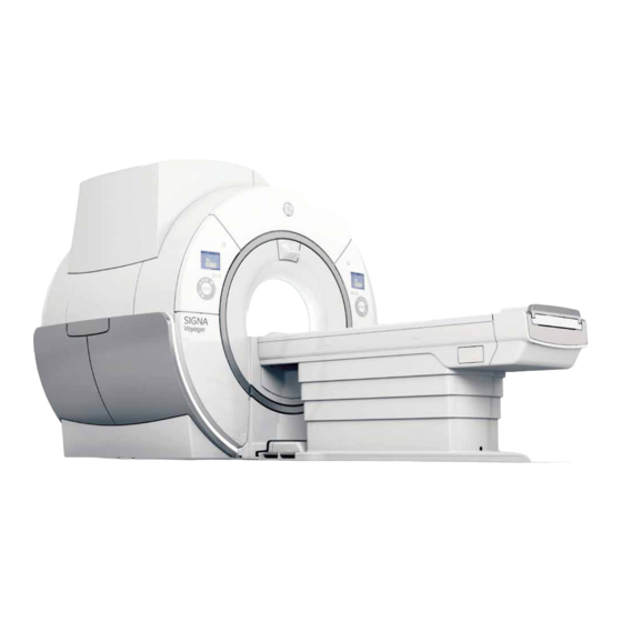
SIGNA Voyager Pre-Installation Direction 5680008–1EN, Revision 2 Chapter 2 General System Level 1 System Components The SIGNA Voyager 1.5T system consists of the following components: Refer to Illustration 2-1. 1.1 Magnet Room 1. 1.5T LCC RD Magnet with Enclosure (MAG) and VibroAcoustic Dampening Kit 2. - Page 22 SIGNA Voyager Pre-Installation Direction 5680008–1EN, Revision 2 Illustration 2-1: System Overview 1 System Components...
-
Page 23: Mr Suite Minimum Room Size Requirement
Equipment room) Customer Site Storage Requirements manual (document 5. Accessory storage. Refer to the number 5182674) or contact the GE Healthcare Project Manager of Installation (PMI) for any additional accessory storage requirements Table 2-1: System Minimum Room Inside Clear Space Dimensions... - Page 24 SIGNA Voyager Pre-Installation Direction 5680008–1EN, Revision 2 NOTE: 1. Must locate center of the magnet to keep minimum service area described in Illustration 2-2. 2. Minimum dimensions are for service only. Room size may grow due to local constraints including magnetic field containment 3.
- Page 25 SIGNA Voyager Pre-Installation Direction 5680008–1EN, Revision 2 Illustration 2-2: Minimum Magnet Service Area (Top View) NOTE: 1. All dimensions are in inches; bracketed dimensions are in millimeters 2. Shaded area indicates minimum service area Chapter 2 General System Level...
- Page 26 SIGNA Voyager Pre-Installation Direction 5680008–1EN, Revision 2 Illustration 2-3: Minimum Magnet Ceiling Height (Top View) NOTE: 1. All dimensions are in inches; bracketed dimensions are in millimeters 2. Shaded area indicates floor to ceiling minimum height of 98.5 (2500) 2 MR Suite Minimum Room Size Requirement...
-
Page 27: Iec Emc Compliance
SIGNA Voyager Pre-Installation Direction 5680008–1EN, Revision 2 3 IEC EMC Compliance Per IEC 60601-1-2 Medical Electrical Equipment requires special precautions regarding Electromagnetic Compatibility (EMC) and must be installed and put into service according to the EMC information provided in the following tables. Full declaration is stored on-site in the user manual delivered with the system. -
Page 28: Mr Seismic Requirements
Contact the Project Manager of Installation for any questions regarding MR system seismic requirements or specifications. 1. The customer is responsible for seismic anchoring of GE components 2. Center of gravity, weight, physical dimensions, and attachment points are provided for seismic calculations. -
Page 29: Mr Suite Acoustic Specifications
Magnet Room Refer to Acoustic Background and Design Guidelines for guidance to contain the noise within the magnet room . NOTE: All GE equipment acoustic output values are for base equipment configuration in each room. Chapter 2 General System Level... -
Page 30: Mr Suite Magnetic Field Specifications
SIGNA Voyager Pre-Installation Direction 5680008–1EN, Revision 2 6 MR Suite Magnetic Field Specifications 6.1 Magnet Fringe Field Illustration 2-4, Illustration 2-5, Illustration 2-6 are the fringe field plots for the 1.5T LCC RD Magnet. These plots illustrate the three-dimensional area of magnetic field without the influence of any nearby ferrous objects or the earth's ambient magnetic field. - Page 31 SIGNA Voyager Pre-Installation Direction 5680008–1EN, Revision 2 Illustration 2-4: 1.5 Tesla LCC RD Magnetic Isogauss Line Plot - Top View Chapter 2 General System Level...
- Page 32 SIGNA Voyager Pre-Installation Direction 5680008–1EN, Revision 2 Illustration 2-5: 1.5 Tesla LCC RD Magnetic Isogauss Line Plot - Front View 6 MR Suite Magnetic Field Specifications...
-
Page 33: Interference From Changing Magnetic Fields
SIGNA Voyager Pre-Installation Direction 5680008–1EN, Revision 2 Illustration 2-6: 1.5 Tesla LCC RD Magnetic Isogauss Line Plot - Side View 6.2 Interference from Changing Magnetic Fields Metal objects moving within the magnet sensitivity lines can produce a field disturbance during clinical imaging. - Page 34 SIGNA Voyager Pre-Installation Direction 5680008–1EN, Revision 2 Illustration 2-7: Magnet Moving Metal Sensitivity Line Plot (Side View) Illustration 2-8: Magnet Moving Metal Sensitivity Line Plot (Top View) 6 MR Suite Magnetic Field Specifications...
- Page 35 SIGNA Voyager Pre-Installation Direction 5680008–1EN, Revision 2 Table 2-5: Magnet Moving Metal Requirements Steel Objects Category Definition Of Distance Location Minimum Distance Radial X Axial ft (m) See Note 1 Objects 100 - 400 lbs distance from isocenter radial x axial (See Note 1)
-
Page 36: Electrical Current
SIGNA Voyager Pre-Installation Direction 5680008–1EN, Revision 2 Illustration 2-9: Actual Axial Shielding Performance 6.3 Electrical Current 1. Electrical current in high voltage power lines, transformers, motors, or generators near the magnet may affect magnetic field homogeneity 6 MR Suite Magnetic Field Specifications... -
Page 37: Non-Mr System Equipment Sensitivity To Magnetic Fields
SIGNA Voyager Pre-Installation Direction 5680008–1EN, Revision 2 2. Magnetic field interference at 50 or 60 Hz must not exceed 40 milligauss RMS respectively at the magnet location (refer to Illustration 2-10) 3. The following equation can be used as a general guide in determining allowable current in feeder lines at a given distance from the magnet isocenter: a. -
Page 38: Magnet Shield
NOTICE If a site has an existing magnetic shield and an upgrade to the LCC RD magnet is being performed, the existing shield must be evaluated by the GE Healthcare MR Siting And Shielding Group. Magnetic shielding is used to reduce the fringe field around the magnet. Refer to Section 6.1... - Page 39 The structural capacity of the site and space availability are important factors in the design of the shield. The GE Healthcare MR Siting & Shielding Group has the capability to design magnetic shields which meet a broad range of site requirements.
-
Page 40: Multiple Mr System Requirements
7.1 Multiple Magnets When installing multiple magnets, the 3 gauss lines must not intersect or the magnets will be interactive. Contact the GE Healthcare Project Manager of Installation (PMI) for any questions regarding magnetic field interaction. Illustration 2-11: Two Magnet Installation... -
Page 41: Shared Equipment Rooms
SIGNA Voyager Pre-Installation Direction 5680008–1EN, Revision 2 7.2 Shared Equipment Rooms When installing multiple MR systems in a shared equipment room, the following conditions must be met: 1. The other system’s cabinet with RF amp must be separated from ISC by at least 79 in. -
Page 42: Mr Suite Temperature And Humidity
SIGNA Voyager Pre-Installation Direction 5680008–1EN, Revision 2 8 MR Suite Temperature and Humidity CAUTION Equipment Failure Failure to maintain the required temperature or humidity at all times (i.e., both working and non-working hours) may result in equipment failure, scanning failure, or warranty void. -
Page 43: Equipment Heat Output Specifications
Actual heat output and room temperature may vary due to environmental factors, room insulation, actual usage, and any non-GE Healthcare equipment used in the MR suite. Also, due to large variations in heat loads, the HVAC system may require unloaders, hot gas bypass, and reheat to maintain humidity levels. -
Page 44: Mr Coolant Requirements
SIGNA Voyager Pre-Installation Direction 5680008–1EN, Revision 2 9 MR Coolant Requirements NOTICE Equipment Failure. A continuous supply of facility liquid coolant to the Integrated Cooling Cabinet (ICC) is required at all times for proper system operation. Failure to provide liquid coolant with the requirements listed in this section may cause equipment failure. - Page 45 SIGNA Voyager Pre-Installation Direction 5680008–1EN, Revision 2 Table 2-11: Facility Water Quality Requirements pH Value 6.5 to 8.2 at 77 °F (25 °C) Electrical Conductivity < 0.8 mmho/cm Chloride Ion < 200 ppm Sulfate Ion < 200 ppm M-Alkalinity < 100 ppm Total Hardness <...
- Page 46 SIGNA Voyager Pre-Installation Direction 5680008–1EN, Revision 2 Illustration 2-12: MR System Water Cooling Block Diagram 9 MR Coolant Requirements...
-
Page 47: Emergency Facility Coolant Requirements
SIGNA Voyager Pre-Installation Direction 5680008–1EN, Revision 2 9.2 Emergency Facility Coolant Requirements The facility may provide an optional backup coolant supply: Cryocooler operation only: Backup coolant may be routed to ICC backup water port for the Cryocooler compressor with the following requirements: 1. - Page 48 SIGNA Voyager Pre-Installation Direction 5680008–1EN, Revision 2 Illustration 2-13: Cryocooler Water Cooling Requirements 9 MR Coolant Requirements...
-
Page 49: Mr Suite Electrical Requirements
10 MR Suite Electrical Requirements 10.1 General Electrical Requirements 1. Customer is required to install a Main Disconnect Panel (MDP). NOTE: GE MDP is orderable OR the customer can procure their own. a. Refer to Section 10.2 for MDP Design Requirements b. - Page 50 SIGNA Voyager Pre-Installation Direction 5680008–1EN, Revision 2 Component Parameter Requirements Power Availability Continuous, facility power is required at all times for operation of the Cryocooler (CRY) to minimize cryogen consumption. Service re‐ Voltage / Frequency 100-120 VAC 50/60 Hz Receptacle required for small power tools. Local volt‐...
- Page 51 SIGNA Voyager Pre-Installation Direction 5680008–1EN, Revision 2 Illustration 2-14: Main Disconnect Panel (MDP) Set-Up Chapter 2 General System Level...
-
Page 52: Main Disconnect Panel (Mdp) Requirements
SIGNA Voyager Pre-Installation Direction 5680008–1EN, Revision 2 10.2 Main Disconnect Panel (MDP) Requirements WARNING PERSONNEL INJURY OR EQUIPMENT DAMAGE CUSTOMER SUPPLIED MDP MUST HAVE CORRECTLY SIZED WIRES AND RATED COMPONENTS TO MEET THE MR SYSTEM POWER REQUIREMENTS. WARNING PERSONNEL INJURY OR EQUIPMENT DAMAGE... - Page 53 Terminal blocks to accept 1 or 2 AWG on the PDU in ISC 8. The optional GE Healthcare MDP consists of the following: a. A 3-pole 200A main circuit breaker rated for the total current of all the sub-breaker circuits b.
-
Page 54: Mr System Shipping And Receiving
2. The customer is responsible for ensuring: a. All floors along the route will support the weight of the magnet (GE Healthcare recommends a structural analysis) b. Doors or other openings are sufficiently wide to allow passage c. -
Page 55: Mr System Component Shipping Specifications
SIGNA Voyager Pre-Installation Direction 5680008–1EN, Revision 2 11.3 MR System Component Shipping Specifications MR system component shipping dimensions and weight are listed below: Table 2-16: MR System Component Shipping Specifications W x D x H Weight MR Component Notes 1.5T LCC RD Magnet... - Page 56 SIGNA Voyager Pre-Installation Direction 5680008–1EN, Revision 2 Illustration 2-15: Magnet Dimensions (as Shipped) NOTE: Dimensions are in inches. Bracketed dimensions are in millimeters. Table 2-17: MR System Component Replacement Shipping Specifications W x D x H Weight Component Notes Replacement RF Body Coil...
- Page 57 SIGNA Voyager Pre-Installation Direction 5680008–1EN, Revision 2 Illustration 2-16: Gradient Coil Cart NOTE: Dimensions are in inches. Bracketed dimensions are in millimeters. Chapter 2 General System Level...
- Page 58 SIGNA Voyager Pre-Installation Direction 5680008–1EN, Revision 2 This page left intentionally blank. 11 MR System Shipping and Receiving...
-
Page 59: Chapter 3 Magnet Room
SIGNA Voyager Pre-Installation Direction 5680008–1EN, Revision 2 Chapter 3 Magnet Room 1 Magnet Room Introduction The Magnet Room is best understood as a series of layers, or “rooms within a room.” Each of these rooms has a specific function and associated requirements. All requirements in this chapter must be followed to ensure safe and proper operation of the MR system. - Page 60 SIGNA Voyager Pre-Installation Direction 5680008–1EN, Revision 2 Illustration 3-1: Magnet Room Layers 1 Magnet Room Introduction...
-
Page 61: Magnet Room Structural Requirements
MR suite and magnet room floor structure. The customer must provide detail defining ferrous material below the magnet to the Project Manager so the GE Healthcare MR Siting and Shielding team can review for compliance. -
Page 62: Vibration Requirements
2. MR Suite HVAC must have vibration isolation 3. A vibration analysis must be performed at the proposed site with the results (and any mitigation) forwarded to the GE Healthcare Project Manager of Installation (PMI). See the Chapter 7, MR Site Vibration Test Guidelines 4. - Page 63 SIGNA Voyager Pre-Installation Direction 5680008–1EN, Revision 2 Illustration 3-2: Magnet Steady State Vibration Specifications Chapter 3 Magnet Room...
-
Page 64: Magnetic Shielded Room Requirements
(not all sites require magnetic shielding). See MR Suite Magnetic Field Specifications for detailed magnetic proximity limit information. 1. The GE Healthcare Project Manager of Installation (PMI) works with the customer to coordinate the magnetic shielding site evaluation 2. If required, the GE Healthcare Project Manager of Installation (PMI) coordinates the delivery of the magnetic shielding design 3. -
Page 65: Acoustic Room Specifications
SIGNA Voyager Pre-Installation Direction 5680008–1EN, Revision 2 4 Acoustic Room Specifications The acoustic room is a layer used to help contain the noise (within the Magnet Room) which is produces during clinical scanning. The following information is provided for the acoustic engineer to design for acoustic noise containment within the Magnet room. -
Page 66: Rf Shielded Room Requirements
SIGNA Voyager Pre-Installation Direction 5680008–1EN, Revision 2 5 RF Shielded Room Requirements 5.1 RF Shielded Room Purpose The RF shielded room is critical to the proper clinical operation of the MR system. RF shielding attenuates the external RF electromagnetic fields. Low RF environments present lower risk to RF impacts to image quality. -
Page 67: Customer Responsibilities
MR System. • NOTE: On request, the GE Healthcare Project Manager of Installation (PMI) can supply a list of RF shielding room vendors. • The RF shielded room may not be in a temperature or humidity controlled environment, the customer must take local measures to prevent RF shield effectiveness degradation. -
Page 68: Requirements
Penetration panels c. Doors d. All windows, including patient viewing window e. Skylights Penetration waveguides installed for GE Healthcare and Non-GE Healthcare options g. Power filters Chapter 7, RF Shielding Effectiveness and Ground Isolation Test Methods provides details for shielding effectiveness measurement based on IEEE Std 299-2006 4. -
Page 69: Rf Shield Test Report
GE panel and the same mounting hardware to be used with the GE penetration panels 5. GE Healthcare Field Engineer must be present during RF SE testing and a test report must be delivered to the PMI 6. Shielding Effectiveness (SE) test equipment must be calibrated NOTE: The calibration cycle of equipment must be no greater than 2 years. -
Page 70: Dock Frame Anchor Mounting Requirements
SIGNA Voyager Pre-Installation Direction 5680008–1EN, Revision 2 a. Manufacturer b. Model c. Serial number d. Current calibration date and calibration due date 13. Results of the dock-table anchor pull test. 5.4.3 Dock Frame Anchor Mounting Requirements Illustration 3-4: dock frame anchor Mounting Options 1. -
Page 71: Rf Shielding Integrity Reliability Requirements
Results must be provided to the GE Healthcare Project Manager of Installation (PMI) 8. The RF shield vendor must provide instructions for removal / replacement of the table anchor without using a torque wrench. Instructions must be given to the GE Healthcare Project Manager of Installation (PMI). -
Page 72: Finished Room Requirements
See Acoustic Room Specifications. Hard, bare wall surfaces may create a harsh scan room environment. Finished walls with acoustic detailing can reduce reflected noise. 1. GE Healthcare recommends walls to protect the RF shielding 2. Walls and any millwork, permanent casework, cabinets, storage areas, acoustic coverings, etc. -
Page 73: Doors, Magnet Access Openings And Patient Viewing Windows
1067 mm) and 72 in. (1829 mm) above the finished floor NOTE: IEC requires the patient, while in the bore, be in full view of the operator. GE Healthcare recommends using a window, although other means (e.g., camera and video display) may be used as long as all IEC requirements are met 6.4 Finished Ceiling... - Page 74 SIGNA Voyager Pre-Installation Direction 5680008–1EN, Revision 2 Illustration 3-5: Cable Concealment Kit Ceiling Opening Dimensions (Top View) NOTE: Dimensions are shown in inches. Bracketed dimensions are in millimeters. 6 Finished Room Requirements...
- Page 75 SIGNA Voyager Pre-Installation Direction 5680008–1EN, Revision 2 NOTE: Illustration 3-6 shows the Concealment Kit frame fasten area dimensions with example of customer supplied support frame. Any types of support frame may be used such as suspended support frame as example 1, supporting beams as example 2, etc that meets all MR requirements.
-
Page 76: Magnet Room Floors
SIGNA Voyager Pre-Installation Direction 5680008–1EN, Revision 2 6.5 Magnet Room Floors 1. The finished floor must support the weight of all components (e.g., patient table, gradient coil replacement cart) throughout operation and service life 2. The finished floor must be water resistant to protect the subfloor and shielding from water damage 3. - Page 77 SIGNA Voyager Pre-Installation Direction 5680008–1EN, Revision 2 Magnet Mounting Detail The positioning of VibroAcoustic Mats. Locations of Magnet Mounting is defind from Magnet Geometric iso center. See Illustration 3-8 Illustration 3-8: Positioning SV VibroAcoustic Mats Chapter 3 Magnet Room...
- Page 78 SIGNA Voyager Pre-Installation Direction 5680008–1EN, Revision 2 Magnet positioning line 1. Magnet positioning line and Dock Frame anchor position is defined from iso center. Illustration 3-9 shows Magnet positioning line that will be used for Magnet alignment. Drawing of line is required before Magnet Installation under the PMI’s responsibility.
-
Page 79: Magnet Room Equipment Specification
SIGNA Voyager Pre-Installation Direction 5680008–1EN, Revision 2 7 Magnet Room Equipment Specification 7.1 Magnet with Enclosure (MAG) Weight: 11,800 lbs (5320 kg) with cryogens. Illustration 3-10: Magnet Enclosure Dimensions NOTE: Dimensions are in inches. Bracketed dimensions are in millimeters. Chapter 3 Magnet Room... -
Page 80: Patient Table (Pt)
SIGNA Voyager Pre-Installation Direction 5680008–1EN, Revision 2 7.2 Patient Table (PT) Weight: 572 lbs (259.5 kg) Illustration 3-11: Patient Table NOTE: Dimensions are in inches. Bracketed dimensions are in millimeters. 7 Magnet Room Equipment Specification... -
Page 81: Magnet Rundown Unit (Mru)
SIGNA Voyager Pre-Installation Direction 5680008–1EN, Revision 2 7.3 Magnet Rundown Unit (MRU) 1. Location: The bottom edge of the MRU must be mounted 60 in. (1524 mm) above the Magnet room floor near the front of the magnet enclosure NOTE: Consider MRU location not to interfere service area around magnet enclosure specified in Room Layout. - Page 82 SIGNA Voyager Pre-Installation Direction 5680008–1EN, Revision 2 Illustration 3-12: Magnet Rundown Unit (MRU) 7 Magnet Room Equipment Specification...
-
Page 83: Magnet Room Venting Requirements
SIGNA Voyager Pre-Installation Direction 5680008–1EN, Revision 2 8 Magnet Room Venting Requirements 8.1 Venting System Requirements The Magnet Room requires the following venting systems: 1. HVAC 2. Emergency Exhaust 3. Pressure Equalization 4. Cryogenic venting 8.2 HVAC Vent Requirements 1. HVAC vendor must comply with Magnet room temperature and humidity specifications and RF shielding specifications 2. - Page 84 SIGNA Voyager Pre-Installation Direction 5680008–1EN, Revision 2 10. The system must have a manual exhaust fan switch near the Operator Workspace (OW) and in the Magnet room near the door (the switches must be connected in parallel) NOTE: If the Magnet room contains an optional oxygen monitor, the Magnet room switch is not required.
-
Page 85: Pressure Equalization Vent Requirement
SIGNA Voyager Pre-Installation Direction 5680008–1EN, Revision 2 Illustration 3-14: Magnet Room Exhaust Fan Schematic with Optional Oxygen Monitor 8.4 Pressure Equalization Vent Requirement 1. A pressure equalizing vent is required in the magnet room ceiling or in the wall, at the highest point possible 2. -
Page 86: Vent Requirements Inside The Magnet Room
2. The cryogenic vent must not transfer load to the magnet adaptor 3. GE Healthcare provides a flanged vent adapter that is 8 in. (203 mm) OD and 24 in. (610 mm) long. GE installs it straight up from the magnet (inline with the waveguide in the RF shield). -
Page 87: Vent Size
SIGNA Voyager Pre-Installation Direction 5680008–1EN, Revision 2 Illustration 3-15: Flanged Magnet Vent Adapter 8.6.2 Vent Size The total pressure drop of the cryogenic vent system (from the magnet vent interface to, and including, the vent cap) must be less than 17 psi (117.2 kPa). The pressure drop of the RF shield waveguide must be included in the overall calculation. -
Page 88: Cryogen Vent Support
Gap between the RF waveguide and GEHC-supplied vent tube must be 1.0 ±0.25 inch (25.4 ±6 mm) b. The outside diameter of the waveguide must match the outside diameter of the GE vent tube within ± 0.125 in. (3 mm) c. - Page 89 SIGNA Voyager Pre-Installation Direction 5680008–1EN, Revision 2 Illustration 3-16: Waveguide Illustration 3-17: Pipe Supports to Remove Vent Load from Ventglas Connection Chapter 3 Magnet Room...
-
Page 90: Vent Requirements Outside The Magnet Room
8.7.2 Vent Construction 1. GE Engineering recommends that the cryogen vent be constructed to the same specification as required inside the Magnet Room. 2. The vent must be routed as directly as possible to the vent cap (i.e., venting system external protective cover) 3. -
Page 91: Vent Exit
SIGNA Voyager Pre-Installation Direction 5680008–1EN, Revision 2 Illustration 3-18: Outside Dielectric Break (Customer-supplied) 8.7.3 Vent Exit WARNING CRYOGENIC BURNS OR ASPHYXIATION DURING A QUENCH, EXTREMELY COLD GAS OR PARTICLES ARE RELEASED FROM THE CRYOGENIC VENTING SYSTEM. A QUENCH MAY OCCUR AT ANY TIME. - Page 92 SIGNA Voyager Pre-Installation Direction 5680008–1EN, Revision 2 b. The bottom of the 90° elbow must be at least 3 feet (0.9 meters) above the roof deck (or higher if at risk of being blocked by drifting snow, sand, etc.) c. The outlet must be covered with a 0.5 inch (12.7 mm) square screen mesh d.
-
Page 93: Combined Vent
SIGNA Voyager Pre-Installation Direction 5680008–1EN, Revision 2 Illustration 3-20: Magnet Cryogenic Vent Location 8.8 Combined Vent A site can combine cryogen venting from two GEHC MR systems. NOTE: The customer chooses this option with the risk that a magnet quench may quench the second magnet. - Page 94 SIGNA Voyager Pre-Installation Direction 5680008–1EN, Revision 2 Illustration 3-21: Combined Vent Combined Vent Illustration Notes: 1. The distance between the magnet and the tie-in point to the large diameter common pipe should be minimized as much as possible. 2. The maximum pressure drop for each magnet between the magnet tie-in to the common pipe and the vent exit to outside shall be less than or equal to 4 psi.
-
Page 95: Magnet Room Electrical And Grounding Requirements
RF shielding 2. The RF Shielded Room vendor must supply electrical line filters for all lines through the RF shielding (excluding electrical lines through the GE supplied Penetration panels) to ensure compliance with the RF Shielded Room attenuation requirements 3. - Page 96 SIGNA Voyager Pre-Installation Direction 5680008–1EN, Revision 2 6. All metallic pipes (including water, medical gas, sprinklers, etc.) entering the RF Shield, excluding the Cryogenic Vent and floor drains, must be located within 56 inches (1422 mm) of the RF Common Ground Stud 7.
-
Page 97: Chapter 4 Equipment Room
Main Disconnect Panel (MDP) Option if applied. 3. If GE MDP is installed, 30A Breaker is also required which is not shown in layout illustration. Refer to MR Suite Electrical Requirements for 30A Breaker details. 4. Regarding “a” in illustration above, 11.8inch (300mm) side space is for excess cable storage. -
Page 98: Components In Equipment Room
SIGNA Voyager Pre-Installation Direction 5680008–1EN, Revision 2 1.2 Components in Equipment Room 1. Integrated System Cabinet (ISC) 2. Integrated Cooling Cabinet (ICC) 3. Magnet Monitor (MON) 4. Main Disconnect Panel (MDP) 5. Optional: Magnetic Resonance Elastography (MRE) 1 Equipment Room Overview... -
Page 99: Equipment Room Hardware Components
SIGNA Voyager Pre-Installation Direction 5680008–1EN, Revision 2 2 Equipment room hardware components 2.1 Integrated System Cabinet (ISC) Weight: 2557 lbs (1160kg) Magnetic Field Limit: 50 gauss (5mT) (Penetration Panel side) Illustration 4-2: Integrated System Cabinet (ISC) NOTE: Dimensions are in inches. Bracketed dimensions are in millimeters. - Page 100 SIGNA Voyager Pre-Installation Direction 5680008–1EN, Revision 2 Illustration 4-3: ISC Anchor Location (For Seismic Area): Front View of ISC Base Cover 2 Equipment room hardware components...
- Page 101 SIGNA Voyager Pre-Installation Direction 5680008–1EN, Revision 2 Illustration 4-4: ISC Anchor Location (For Seismic Area): Right View of ISC Base Cover NOTE: The right view of ISC anchor locations is symmetry of the left side. Chapter 4 Equipment Room...
-
Page 102: Integrated Cooling Cabinet (Icc)
SIGNA Voyager Pre-Installation Direction 5680008–1EN, Revision 2 2.2 Integrated Cooling Cabinet (ICC) Weight: 1034lbs (469kg) with F-50 Cryocooler Compressor 264 lbs (120 kg) NOTE: Weight of ICC without F-50 Cryocooler Compressor is 770 lbs (349kg) Magnetic Field Limit: 50 gauss (5mT) (Penetration Panel side) - Page 103 SIGNA Voyager Pre-Installation Direction 5680008–1EN, Revision 2 Illustration 4-6: ICC Anchor Location (For Seismic Area): Front View of ICC Base Cover Chapter 4 Equipment Room...
- Page 104 SIGNA Voyager Pre-Installation Direction 5680008–1EN, Revision 2 Illustration 4-7: ICC Anchor Location (For Seismic Area): Right View of ICC Base Cover NOTE: The right view of ICC Anchor Location is symmetry of left side. 2 Equipment room hardware components...
-
Page 105: Magnet Monitor (Mon) Requirements And Specifications
SIGNA Voyager Pre-Installation Direction 5680008–1EN, Revision 2 2.3 Magnet Monitor (MON) Requirements and Specifications 2.3.1 Requirements 1. Customer must supply 100Base-T network connection with RJ45 connector to the Magnet Monitor (MON) 2. The network connection must not be routed through the Ethernet switch in the Global Operator Cabinet (GOC) 3. - Page 106 SIGNA Voyager Pre-Installation Direction 5680008–1EN, Revision 2 Illustration 4-8: Magnet Monitor (MON) 2 Equipment room hardware components...
-
Page 107: Main Disconnect Panel (Mdp) Option
SIGNA Voyager Pre-Installation Direction 5680008–1EN, Revision 2 2.4 Main Disconnect Panel (MDP) Option 1. Weight: 130 lbs (59 kg) 2. Magnetic Field Limit: 50 Gauss (5 mT) Illustration 4-9: Main Disconnect Panel Chapter 4 Equipment Room... -
Page 108: Magnetic Resonance Elastography (Mre) Option
SIGNA Voyager Pre-Installation Direction 5680008–1EN, Revision 2 2.5 Magnetic Resonance Elastography (MRE) Option 2.5.1 Requirements 1. Customer must work with the RF shield vendor to provide a waveguide for the 1 in. (25.4 2. MRE Resoundant Acoustic Driver location is limited to the length of the 1 in. (25.4 mm) tube (see the usable cable lengths in Chapter 6, Section 1.4, Magnetic Resonance Elastography... -
Page 109: Isc And Icc Construction Requirements
SIGNA Voyager Pre-Installation Direction 5680008–1EN, Revision 2 3 ISC and ICC Construction Requirements This section describes the special consideration of Integrated System Cabinet (ISC) and Integrated Cooling Cabinet (ICC). Specification of Floor under ISC and ICC: 1. Floor slope: < +/- 0.5 deg ( < +/- 8.7mm / m) 2. - Page 110 SIGNA Voyager Pre-Installation Direction 5680008–1EN, Revision 2 5. In case the gap in between ISC and ICC is 15mm (minimum gap) and slope is down to the center from both side like “V” shape, the slope specification is < 0.25 deg.
- Page 111 SIGNA Voyager Pre-Installation Direction 5680008–1EN, Revision 2 Illustration 4-14 shows the following two specifications. • Minimum top area including cable tray or ceiling for air flow and servicing. • Distance between RF Shield (from Magnet Room) and ISC/ICC Pen Wall per Mesh Shield flexibility.
-
Page 112: Isc And Icc Wall Opening Requirements
GE Penetration Panel and Mesh Shield Tunnel. It is the facility's responsibility to ensure that the RF Shielded Room Vendor testing meets the attenuation... - Page 113 SIGNA Voyager Pre-Installation Direction 5680008–1EN, Revision 2 Illustration 4-15 shows the equipment room side view of the wall opening. The dotted line shows the out line of the ISC. Make sure that the wall cut out is not symmetric with ISC center.
- Page 114 SIGNA Voyager Pre-Installation Direction 5680008–1EN, Revision 2 Illustration 4-16 shows the Mesh Shield fringe attachment area of RF shield plane (View from Magnet Room Side). NOTE: RF shield plane in Mesh Shield fringe attachment area must be flat. NOTE: For finished wall, cut the area inside of PEN Closet till the RF Shield plane appears as...
- Page 115 SIGNA Voyager Pre-Installation Direction 5680008–1EN, Revision 2 NOTE: Mesh shield will be installed from Magnet Room side. Mesh shield fringe attachment area of RF shield must be prepared at Magnet Room side. Illustration 4-17: Mesh shield Attachment Note Chapter 4 Equipment Room...
- Page 116 SIGNA Voyager Pre-Installation Direction 5680008–1EN, Revision 2 Illustration 4-18 shows screw location for Mesh Shield and Penetration Panel. NOTICE M5 screws are used to fix Mesh Shields to the RF Shield from Magnet Room side. It’s RF vendor’s responsibility to prepare M5 screws according to the site condition. Prepare 230 screws (and nuts).
- Page 117 Minimum closet inner dimensions outline RF Shield Pen Wall Covers are fixed to mesh shield by GE supplied screws 11.8in (300mm) side space is for excess cable storage. Left side space and right side space 11.8 (300) can be swapped.
- Page 118 Minimum closet inner dimensions outline RF Shield Pen Wall Covers are fixed to mesh shield by GE supplied screws 11.8inch (300mm) side space is for excess cable storage. Left side space 5.9(150) and right side space 11.8 (300) can be swapped.
- Page 119 Minimum closet inner dimensions outline RF Shield Pen Wall Covers are fixed to mesh shield by GE supplied screws 11.8inch (300mm) side space is for excess cable storage. Left side space 5.9(150) and right side space 11.8 (300) can be swapped.
- Page 120 SIGNA Voyager Pre-Installation Direction 5680008–1EN, Revision 2 This page left intentionally blank. 4 ISC and ICC Wall Opening Requirements...
-
Page 121: Chapter 5 Operator Room
SIGNA Voyager Pre-Installation Direction 5680008–1EN, Revision 2 Chapter 5 Operator Room 1 Operator Workspace (OW1) Illustration 5-1: Operator Workspace (OW1) Overall Dimensions NOTE: Dimensions are in inches. Bracketed dimensions are in millimeters. Chapter 5 Operator Room... - Page 122 SIGNA Voyager Pre-Installation Direction 5680008–1EN, Revision 2 GOC Computer Cabinet (OW1 A2) Weight: 122.8 lbs (55.7 Kg). Magnetic Field Limit: 50 gauss (5mT) Illustration 5-2: GOC Computer Cabinet (OW1 A2) NOTE: Dimensions are in inches. Bracketed dimensions are in millimeters.
- Page 123 SIGNA Voyager Pre-Installation Direction 5680008–1EN, Revision 2 Operator Workspace Components Position on Table Top Weight - with stand: 19.8 lbs (9 Kg). Weight - without stand: 13.2 lbs (6 Kg). Magnetic Field Limit: 50 gauss (5mT) Illustration 5-3: Operator Workspace Components Position on Table Top - Host LCD...
- Page 124 SIGNA Voyager Pre-Installation Direction 5680008–1EN, Revision 2 Illustration 5-4: Operator Worspace Components Position on Table Top - Keyboard 1 Operator Workspace (OW1)
-
Page 125: Pneumatic Patient Alert (Pa1)
SIGNA Voyager Pre-Installation Direction 5680008–1EN, Revision 2 2 Pneumatic Patient Alert (PA1) Weight: 0.5 lbs (0.2 Kg). Magnetic Field Limit: 100 gauss (10mT) Illustration 5-5: Pneumatic Patient Alert Control Box (PA1) Chapter 5 Operator Room... -
Page 126: Oxygen Monitor (Oxy) Option
SIGNA Voyager Pre-Installation Direction 5680008–1EN, Revision 2 3 Oxygen Monitor (OXY) Option The optional Oxygen Monitor system consists of the Oxygen Monitor, the Remote Oxygen Sensor Module, and interconnects through the Pen Wall in ICC. The Oxygen Monitor alarm is located near the Operator Workspace is activated by the Remote Oxygen Sensor Module in the Magnet Room. - Page 127 SIGNA Voyager Pre-Installation Direction 5680008–1EN, Revision 2 Illustration 5-6: Oxygen Monitor and Remote Sensor Chapter 5 Operator Room...
- Page 128 SIGNA Voyager Pre-Installation Direction 5680008–1EN, Revision 2 This page left intentionally blank. 3 Oxygen Monitor (OXY) Option...
-
Page 129: Chapter 6 System Interconnections
Chapter 6 System Interconnections 1 MR System Interconnects Specifications 1.1 Component Designator Definitions GE Healthcare uses Component Designators to identify system components. All subsystem cabinets and other components are referred to by their component designators in the Interconnect Data diagrams and tables. -
Page 130: Usable Cable Lengths
SIGNA Voyager Pre-Installation Direction 5680008–1EN, Revision 2 1.2 Usable Cable Lengths Four configurations of cable lengths are available for order. Measure the distances between the equipment and compare them to the distances specified in the tables. If the your distance is less than the short distance specified, the Site Option is “Short”;... -
Page 131: Long / Short Cable Selection Guidance
SIGNA Voyager Pre-Installation Direction 5680008–1EN, Revision 2 1.3 Long / Short cable selection guidance This section describes the Long / Short cable selection guidance referring to Illustration 6-1. NOTE: This guidance is based on the assumption that the distance between cable tray and floor is 8.53 feet (2.6m). -
Page 132: Magnetic Resonance Elastography (Mre) Option
SIGNA Voyager Pre-Installation Direction 5680008–1EN, Revision 2 1.4 Magnetic Resonance Elastography (MRE) Option Table 6-5: MRE Option Usable Cable Lengths Site Option A: Site Option B: Site Option C: Short ER, Short Long ER, Short Short ER, Long Cable Part number... -
Page 133: Mr System Interconnects Routing Requirements
SIGNA Voyager Pre-Installation Direction 5680008–1EN, Revision 2 2 MR System Interconnects Routing Requirements 2.1 General Requirements 1. The customer is responsible for the purchase and installation of all cable support mechanisms 2. Any type of cable support may be used, such as commercially available Ladder or Channel... -
Page 134: Magnet Room Requirements
SIGNA Voyager Pre-Installation Direction 5680008–1EN, Revision 2 Illustration 6-2: Obstruction Example 2.2 Magnet Room Requirements 1. Two cable trays must be used, each at least 18 in. (457 mm) wide 2. Installation and routing of cable trays must be coordinated with the RF shield vendor 3. -
Page 135: Recommended Cable Groupings
SIGNA Voyager Pre-Installation Direction 5680008–1EN, Revision 2 2.2.1 Recommended Cable Groupings We recommend the grouping order shown below. The cable groups must not touch. Local code may require dividers, channeling, bundling, etc. • Group a — Gradient and RF common ground cables. In the Magnet room, the gradient cable group must be laid in a single layer. - Page 136 SIGNA Voyager Pre-Installation Direction 5680008–1EN, Revision 2 Illustration 6-4: Cable Tray Requirements (Side-By-Side) 2 MR System Interconnects Routing Requirements...
- Page 137 SIGNA Voyager Pre-Installation Direction 5680008–1EN, Revision 2 Illustration 6-5: Cable Tray Requirements (Stacked) Chapter 6 System Interconnections...
-
Page 138: Equipment Room Requirements
SIGNA Voyager Pre-Installation Direction 5680008–1EN, Revision 2 Illustration 6-6: Cable Tray Requirements (90° Magnet Interface) 2.3 Equipment Room Requirements 1. All equipment interconnects must route overhead 2. Cables/hoses must drop through the bottom or off the end of the cable support directly to the top of the cabinets 3. - Page 139 SIGNA Voyager Pre-Installation Direction 5680008–1EN, Revision 2 Table 6-6: Minimum Cable Tray Width 18 in. (450 mm) 12 in. (300 mm) Electrical, Water Electrical NOTE: Local Contractor to determine final size/ support needed to support cables. Chapter 6 System Interconnections...
-
Page 140: Mr System Cable Specifications
SIGNA Voyager Pre-Installation Direction 5680008–1EN, Revision 2 3 MR System Cable Specifications Table 6-7: MR System Cable Information Con‐ Cable nector Tempera‐ bend ra‐ Number Voltage Diame‐ Size/ Certifica‐ ture Rat‐ RUN# FROM Length (mm) dius of con‐ Rating Diame‐... - Page 141 SIGNA Voyager Pre-Installation Direction 5680008–1EN, Revision 2 M3313 Table 18,500 69.32 UL2464 M3392 Table 18,000 4.32 31.2 38.1 -55/200 M4005 17,500 15.3 20.5 UL1284 M3391 18,500 53.04 UL2464 M5006 Harness (M2026, M2027, M2028, M2029) UL1651 M2026 MAG IRD 18,000 25.04...
- Page 142 SIGNA Voyager Pre-Installation Direction 5680008–1EN, Revision 2 E2027 30,000 26.8 OFNR 0 to 50 E2029 30,000 26.8 OFNR 0 to 50 UL1651 E2026 30,000 25.04 -20 to 85 UL1651 E2028 30,000 25.04 -20 to 85 RF Door E3014 25,000 30.8...
- Page 143 SIGNA Voyager Pre-Installation Direction 5680008–1EN, Revision 2 Long:10,000 E0007 16.5 UL2501 Short:4,500 E3040 4,500 12.7 53.035 UL2464 E0010 5,000 43.09 UL2464 E0007 4,000 16.5 UL2501 Chapter 6 System Interconnections...
-
Page 144: Facility Supplied System Interconnects Specifications
SIGNA Voyager Pre-Installation Direction 5680008–1EN, Revision 2 4 Facility Supplied System Interconnects Specifications NOTICE On installation sites in China, please make sure that the power cables and ground cables provided by customers have China Compulsory Certification (CCC). This information is supplied to the customer by Part Number 5159493 'China Power Cable Requirements'. - Page 145 The RF shielded room vendor must supply and install RF door switches on all RF shielded doors. These switches must be wired in series and a GE supplied cable (two loose lead conductors) will attach to one door switch. RF Switches must be rated for 10V DC maximum and the switches must be in the open position when the doors are open (switch contacts close when the doors are completely closed).
- Page 146 SIGNA Voyager Pre-Installation Direction 5680008–1EN, Revision 2 This page left intentionally blank. 4 Facility Supplied System Interconnects Specifications...
-
Page 147: Chapter 7 Appendix
SIGNA Voyager Pre-Installation Direction 5680008–1EN, Revision 2 Chapter 7 Appendix 1 Glossary Abbreviation for Broadband Cryogen A substance for producing low temperatures. Liquid helium is the cryogen used to cool the magnet to approximately 4 Kelvin (-269°C or -452°F). Cryostat An apparatus maintaining a very low constant temperature. - Page 148 SIGNA Voyager Pre-Installation Direction 5680008–1EN, Revision 2 Magnetic Field (B) A condition in a region of space established by the presence of a magnet and characterized by the presence of a detectable magnetic force at every point in the region. A magnetic field exists in the space around a magnet (or current carrying conductor) and can produce a magnetizing force on a body within it.
- Page 149 SIGNA Voyager Pre-Installation Direction 5680008–1EN, Revision 2 Superconducting Magnet A magnet whose magnetic field originates from current flowing through a superconductor. Such a magnet is enclosed in a cryostat. Superconductor A substance whose electrical resistance essentially disappears at temperatures near zero Kelvin.
-
Page 150: Mr Site Vibration Test Guidelines
SIGNA Voyager Pre-Installation Direction 5680008–1EN, Revision 2 2 MR Site Vibration Test Guidelines 2.1 Test Measurements 1. Vibration measurements must be in the range of 10 g. Test equipment must have the required sensitivity to these levels 2. Instrumentation must have a low tolerance to temperature effects since many times the low frequency thermal drift may influence the measurements 3. -
Page 151: Data Collection
From this data, GE Heatlhcare can help determine compliance with the vibration guidelines 4. The test consultant must provide site data to show the design recommendations for all sites/... - Page 152 Propose a solution to the problem c. Find an alternate site location 5. Any questions regarding test equipment requirements, test parameters, or general questions should be discussed with the GE Healthcare Project Manager of Installation (PMI) 2 MR Site Vibration Test Guidelines...
- Page 153 SIGNA Voyager Pre-Installation Direction 5680008–1EN, Revision 2 Illustration 7-1: Example of Site Environmental Vibration Levels Chapter 7 Appendix...
- Page 154 SIGNA Voyager Pre-Installation Direction 5680008–1EN, Revision 2 Illustration 7-2: Example Site Environmental Vibration 2 MR Site Vibration Test Guidelines...
- Page 155 SIGNA Voyager Pre-Installation Direction 5680008–1EN, Revision 2 Illustration 7-3: Acceleration Time History Chapter 7 Appendix...
- Page 156 SIGNA Voyager Pre-Installation Direction 5680008–1EN, Revision 2 Illustration 7-4: Acceleration Time History (Zoomed In on Transient Event) 2 MR Site Vibration Test Guidelines...
-
Page 157: Rf Shielding Effectiveness And Ground Isolation Testing
SIGNA Voyager Pre-Installation Direction 5680008–1EN, Revision 2 3 RF Shielding Effectiveness and Ground Isolation Testing 3.1 Ambient Radio Frequency Interference (RFI) The MR System operates with a highly sensitive RF receiving front end to be able to capture the signal of an object scanned. A Limited level of RF interference (RFI) at the installation site is needed for the proper operation for the MR System. -
Page 158: Rf Shielding Effectiveness (Se) And Ground Isolation Test Methods
SIGNA Voyager Pre-Installation Direction 5680008–1EN, Revision 2 1. The ambient RFI measured should be less than 100 millivolt per meter (100 dB microvolt per meter) 2. The recommended centerband and bandwidth frequencies to be used when measuring RFI are listed in the table below. (This table includes frequency bands important for both imaging... -
Page 159: Test Set-Up For Rf Shielded Room
4. AC power supplied through low-pass filters 5. Patient view window, skylights, windows, hatches, etc. 6. Frames and blank penetration panels installed, dimensionally equivalent to the GE panel and the same mounting hardware to be used with the GE penetration panel. -
Page 160: Test Frequency
SIGNA Voyager Pre-Installation Direction 5680008–1EN, Revision 2 b. RF Power Amplifier (if required) c. DC Power Supply (if required) d. Tuned λ/2 Dipole antenna at the test frequencies or broadband biconical antenna NOTE: Considering the dimensions for the a tuned λ/2 dipole antenna at lower frequencies, it is more practical to use a broadband biconical antenna. -
Page 161: Shielding Effectiveness Measurement
SIGNA Voyager Pre-Installation Direction 5680008–1EN, Revision 2 Illustration 7-5: Antenna Positioning 3. Measurements are taken with horizontal and vertical antenna polarizations. Both Transmit (TX) and Receive (RX) antennas must be aligned with the same polarization, the measured polarization must be part of the test report 4. - Page 162 SIGNA Voyager Pre-Installation Direction 5680008–1EN, Revision 2 Illustration 7-6: Reference Level Measurement 3. The antennas must be separated by a distance of 2 m, minimum, unless physical spacing limitations for either the reference level or SE readings preclude maintaining that spacing. In...
-
Page 163: Attenuated Level Measurement
SIGNA Voyager Pre-Installation Direction 5680008–1EN, Revision 2 ii. With vertical polarization for both antennas, the receive antenna must be moved horizontally right 1.0 m from the initial position, and then move it left from the initial position to 1.0 m. Then starting 1 m above the initial position, move slowly horizontally right 1 m and then horizontally left 1 m from initial position. -
Page 164: Shielding Effectiveness Calculation
SIGNA Voyager Pre-Installation Direction 5680008–1EN, Revision 2 above initial position and 0.3 m above the floor and 1m to the left and right of the initial position, see Illustration 7-7 iv. Measure and record the highest power in this volume b. -
Page 165: Rf Shield Test Report
SIGNA Voyager Pre-Installation Direction 5680008–1EN, Revision 2 c. Take a reading and record the value 3.3.9 RF Shield Test Report A test report must be prepared by the testing organization performing the shielding effectiveness and ground isolation resistance tests for the RF shielded room. The test report includes data necessary for the evaluation of the shielding effectiveness performance and ground isolation of the RF shielded room. - Page 166 SIGNA Voyager Pre-Installation Direction 5680008–1EN, Revision 2 Test set-up for attenuated level measurement 3 RF Shielding Effectiveness and Ground Isolation Testing...
-
Page 167: Acoustic Background And Design Guidelines
SIGNA Voyager Pre-Installation Direction 5680008–1EN, Revision 2 4 Acoustic Background and Design Guidelines The acoustic information is provided for site planning and architectural design activities to address acoustics to meet local regulations and customer requirements. For more information about recommended safety procedures regarding patient exposure to MR generated acoustic levels, see the MR Safety Guide included with the system Users Manual. -
Page 168: Acoustic Design Guidelines
SIGNA Voyager Pre-Installation Direction 5680008–1EN, Revision 2 • In-house library facilities 4.2 Acoustic Design Guidelines 4.2.1 Magnet Room Noise generated by the MR system is inherent to the operation of the system. The sound quality (human perception) within the Magnet Room can be modified by including sound absorbing materials to make the room sound more subdued and less harsh. - Page 169 SIGNA Voyager Pre-Installation Direction 5680008–1EN, Revision 2 hardening) and fiberglass batt material. See examples of wall construction shown in Illustration 7-8 Illustration 7-9. • The top of the wall must join the ceiling/floor above so that no cracks or gaps occur. If metal pan is used on the ceiling/floor (above), then flute seals would be used to seal the gaps between the drywall and the pan.
-
Page 170: High Bay Rf Room
SIGNA Voyager Pre-Installation Direction 5680008–1EN, Revision 2 Illustration 7-9: Example Of Wall Construction For Airborne Noise Control - Option 2 4.2.2.2 High Bay RF Room A high bay RF Room is a self contained RF Room which has open air space between the RF Room ceiling and the building floor above. - Page 171 SIGNA Voyager Pre-Installation Direction 5680008–1EN, Revision 2 • RF windows should be purchased as window/frame units with an STC rating obtained from laboratory testing per ASTM standards. STC 50 to 60 windows are needed. The installation must include proper sealing to avoid sound leaks.
-
Page 172: Sample Calculation Ac Power Equipment Minimum Distance
SIGNA Voyager Pre-Installation Direction 5680008–1EN, Revision 2 5 Sample Calculation AC Power Equipment Minimum Distance This is a sample calculation to determine minimum distance from a feeder, transformer, or other AC electrical source, using the Formula found in Magnetic Field Consideration Electrical Current subsection to determine minimum distance from a feeder, transformer, or other AC electrical source. -
Page 173: Selecting Magnet Anchor Size
SIGNA Voyager Pre-Installation Direction 5680008–1EN, Revision 2 6 Selecting Magnet Anchor Size The following is an example to illustrate the selection of proper anchors to install a Magnet in a building with 2000 psi (13.8 MPa) concrete. For this example the area is not under seismic requirements. - Page 174 SIGNA Voyager Pre-Installation Direction 5680008–1EN, Revision 2 Illustration 7-11: Allowable Anchor Loads in Concrete (Metric Units) 6 Selecting Magnet Anchor Size...
-
Page 175: Magnet Cryogenic Venting Pressure Drop Reference Tables
SIGNA Voyager Pre-Installation Direction 5680008–1EN, Revision 2 7 Magnet Cryogenic Venting Pressure Drop Reference Tables Use the following tables to calculate the cryogenic vent pressure drop through the pipe used. Table 7-3: 1.5T Magnet Cryogenic Vent System Pressure Drop Matrix... - Page 176 SIGNA Voyager Pre-Installation Direction 5680008–1EN, Revision 2 Inside Distance of vent system Pressure drop for Pressure Drop Per Elbow Used Anywhere Within A 20 Ft (6.1 M) Vent Segment dia. of component from magnet straight pipe with Standard Sweep Long Sweep vent smooth inside sur‐...
- Page 178 © 2016 General Electric Company. All Rights Reserved. www.gehealthcare.com...
Need help?
Do you have a question about the SIGNA Voyager and is the answer not in the manual?
Questions and answers