Cambium Networks PTP 820 Series User Manual
Split-mount system
Hide thumbs
Also See for PTP 820 Series:
- Installation manual (179 pages) ,
- Manual (29 pages) ,
- Installation instructions (3 pages)
Table of Contents
Advertisement
Quick Links
Advertisement
Chapters
Table of Contents

Related Manuals for Cambium Networks PTP 820 Series


Summary of Contents for Cambium Networks PTP 820 Series
- Page 1 User Guide...
- Page 2 Accuracy While reasonable efforts have been made to assure the accuracy of this document, Cambium Networks assumes no liability resulting from any inaccuracies or omissions in this document, or from use of the information obtained herein. Cambium reserves the right to make changes to any products described herein to improve reliability, function, or design, and reserves the right to revise this document and to make changes from time to time in content hereof with no obligation to notify any person of revisions or changes.
-
Page 3: Table Of Contents
Contents About This User Guide ............................1 Contacting Cambium Networks ........................2 Purpose ................................3 Cross references .............................. 3 Feedback ................................. 3 Problems and warranty ............................4 Reporting problems ............................4 Repair and service ............................4 Hardware warranty ............................4 Security advice ................................ - Page 4 Contents Ethernet Management Interfaces ......................1-14 E1/DS1 Interface (Optional) ........................1-15 Radio Interfaces............................1-15 Power Interface ............................1-15 Synchronization Interface ......................... 1-15 Terminal Interface ............................. 1-15 External Alarms ............................1-16 RFU Overview ..............................1-17 Radio Frequency Units (RFUs) were designed with sturdiness, power, simplicity, and compatibility in mind. These advanced systems provide high-power transmission for short and long distances and can be assembled and installed quickly and easily.
- Page 5 Contents Determining ETSI or ANSI (FCC) TDM Mode ..................... 2-26 Configuring the Activation Key ......................... 2-27 Viewing the Activation Key Status Parameters ..................2-27 Entering the Activation Key ........................2-29 Activating a Demo Activation Key ......................2-29 Displaying a List of Activation-Key-Enabled Features ................2-29 Setting the Time and Date (Optional) .......................
- Page 6 Contents Displaying LACP Port Statistics ........................3-47 Displaying LACP Port Debug Staistics ......................3-48 Configuring XPIC ............................... 3-50 Prerequisites for XPIC ..........................3-50 Configuring the Carriers ..........................3-50 Creating an XPIC Group ..........................3-51 Performing Antenna Alignment for XPIC ....................3-53 Deleting an XPIC Group ..........................
- Page 7 Contents Configuring Unit Parameters ..........................4-35 Configuring NTP ..............................4-37 Displaying Unit Inventory..........................4-39 Chapter 5: Radio Configuration ........................5-1 Viewing the Radio Status and Settings ....................... 5-2 Configuring the IDU-RFU Connection (PTP 820F only) ..................5-5 Configuring the Remote Radio Parameters ......................5-8 Configuring ATPC and Override Timer ......................
- Page 8 Contents Chapter 7: Quality of Service (QoS) ......................7-1 QoS Overview ..............................7-2 Configuring Classification ............................ 7-4 Classification Overview ..........................7-4 Configuring Ingress Path Classification on a Logical Interface ..............7-5 Modifying the C-VLAN 802.1Q UP and CFI Bit Classification Table ............. 7-8 Modifying the S-VLAN 802.1 UP and DEI Bit Classification Table ..............
- Page 9 Contents Viewing the ERPI Configuration and Status Parameters ................8-9 Viewing ERPI State Information ........................ 8-10 Initiating a Manual or Forced Switch and Clearing the Switch or Initiating Reversion ......8-12 Blocking or Unblocking R-APS Messages on a Service Point ..............8-12 Viewing ERPI Statistics ..........................
- Page 10 Contents Configuring OEM for Pseudowire Services ....................9-41 Configuring Pseudowire Tunnels and Tunnel Groups ................9-47 Configuring Pseudowire Profiles ....................... 9-56 Configuring Pseudowire TDM Services Manually ..................9-60 Displaying TDM PMs ............................9-66 Displaying E1/DS1 PMs ..........................9-66 Displaying Native TDM Service PMs ......................9-68 Displaying Pseudowire Service PMs ......................
- Page 11 Contents Uploading the Configuration Log ........................11-44 Chapter 12: Alarm Management and Troubleshooting ................12-1 Viewing Current Alarms ............................ 12-2 Viewing Alarm Statistics ............................ 12-4 Viewing the Event Log............................12-5 Editing Alarm Text and Severity ........................12-7 Displaying Alarm Information ........................12-7 Viewing the Probable Cause and Corrective Actions for an Alarm Type ...........
- Page 12 Contents Installing an Activation Key (CLI) ......................14-17 Displaying Activation Key Information (CLI) .................... 14-17 Activating an Activation Key (CLI) ......................14-17 Setting the Time and Date (Optional) (CLI) ..................... 14-19 Enabling the Interfaces (Interface Manager) (CLI) ..................14-22 Enabling the Second Management Interface (CLI) .................. 14-23 Configuring Cascading Interfaces (Optional) (CLI) ..................
- Page 13 Contents Deleting an XPIC Group (CLI) ........................15-22 Configuring HSB Radio Protection (CLI) ......................15-23 HSB Radio Protection Overview (CLI) ...................... 15-23 Configuring 1+1 HSB without Space Diversity (CLI) ................. 15-23 Configuring 1+1 HSB with Space Diversity (CLI) ..................15-24 Copying Configuration to Mate (CLI) .......................
- Page 14 Contents Displaying Communication Status with the Remote Radio (CLI) ............... 17-4 Displaying the Remote Radio’s Link ID and Location (CLI) ................ 17-4 Muting and Unmuting the Remote Radio (CLI) ..................17-4 Displaying the Remote Radio’s RX Level (CLI) ................... 17-5 Configuring the Remote Radio’s TX Level (CLI) ..................
- Page 15 Contents Adding a Description for the Interface (CLI) .................... 18-38 Configuring Automatic State Propagation and Link Loss Forwarding (CLI) ............. 18-40 Configuring Automatic State Propagation to an Ethernet Port (CLI) ............18-40 Viewing Ethernet PMs and Statistics (CLI) ...................... 18-43 Displaying RMON Statistics (CLI) ......................
- Page 16 Contents Configuring Queue Priority (CLI)......................19-40 Configuring Interface Priority Profiles (CLI) ..................... 19-41 Attaching a Priority Profile to an Interface (CLI) ..................19-44 Configuring Weighted Fair Queuing (WFQ) (CLI) ..................19-44 Displaying Egress Statistics (CLI) ........................19-49 Displaying Queue-Level PMs (CLI) ......................19-49 Displaying Service Bundle-Level PMs (CLI) ....................
- Page 17 Contents Configuring an Ethernet Interface as a Synchronization Source (CLI) ............22-2 Configuring a Radio Interface as a Synchronization Source (CLI) .............. 22-4 Clearing All Sync Sources (CLI) ........................22-6 Configuring the Outgoing Clock (CLI) ........................ 22-7 Configuring SSM Messages (CLI) ........................22-9 Configuring the Revertive Timer (CLI) ......................
- Page 18 Contents Viewing Current Alarms (CLI) ..........................24-2 Viewing the Event Log (CLI) ..........................24-3 Editing Alarm Text and Severity (CLI) ........................ 24-4 Displaying Alarm Information (CLI) ......................24-4 Editing an Alarm Type (CLI) ........................24-4 Setting Alarms to their Default Values (CLI) ....................24-5 Configuring a Timeout for Trap Generation (CLI) .....................
- Page 19 Contents Management Interface Pin-Outs ......................28-19 Management Interface LEDs ........................28-19 E1/DS1 Interface LEDs and Pin-Outs – PTP 820F .................... 28-20 E1/DS1 Interface Pin-Outs ........................28-20 E1/DS1 Interface LEDs ..........................28-22 Radio Interface LEDs and Pin-Outs – PTP 820F ....................28-24 Radio RJ-45 Interface Pin-Outs ........................
- Page 20 Contents List of Figures Figure 1 PTP 820F Front Panel and Interface......................1-7 Figure 2 GbE Combo Interface Numbering ....................... 1-8 Figure 3 RFU3/ SFP5-6 Interfaces ..........................1-8 Figure 4 Management Interface Pin Connections ....................1-9 Figure 5 SM Card and Cover ........................... 1-11 Figure 6 PTP 820G Front Panel and Interfaces .......................
- Page 21 Contents Figure 42 MRMC Symmetrical Scripts Page (ETSI) – PTP 820G ................2-47 Figure 43 MRMC Symmetrical Scripts Page (ANSI) ....................2-47 Figure 44 MRMC Symmetrical Scripts Page (Configuration) – PTP 820F ..............2-48 Figure 45 MRMC Symmetrical Scripts Page (Configuration) - PTP 820G ..............2-48 Figure 46 MRMC Symmetrical Scripts Page (Configuration –...
- Page 22 Contents Figure 83 N + 0 Multi Carrier ABC Quick Configuration Wizard – Radio Parameters Configuration Page – PTP 820F 3- Figure 84 N + 0 Multi Carrier ABC Quick Configuration Wizard – Radio Parameters Configuration Page (XPIC) – PTP 820G .................................
- Page 23 Contents Figure 120 Create Radio Protection Group Page – Member 1 (Space Diversity Group Selected) ......3-59 Figure 121 Create Radio Protection Group Finish Page (Space Diversity Group Selected) ........3-59 Figure 122 Radio Protection Page (Populated) ....................... 3-61 Figure 123 Radio Protection Groups – Edit Page ....................3-61 Figure 124 Radio Protection Groups –...
- Page 24 Contents Figure 162 Radio Ethernet Interface Configuration Page ..................5-15 Figure 163 Radio Ethernet Interface Configuration – Edit Page ................5-16 Figure 164 Radio Ethernet Interface Configuration Page ..................5-17 Figure 165 Radio Ethernet Interface Configuration – Edit Page ................5-18 Figure 166 Radio Ethernet Interface Counters Page ....................
- Page 25 Contents Figure 204 RMON Page – Hiding and Displaying Columns ..................6-31 Figure 205: Egress CoS Statistics Page ........................6-32 Figure 206: Egress CoS Statistics – Edit Page ......................6-32 Figure 207 Ethernet Port TX PM Report Page ......................6-34 Figure 208 Ethernet PM Port Admin Page ......................
- Page 26 Contents Figure 246 Scheduler Priority Profile Page ......................7-38 Figure 247 Scheduler Priority Profile – Add Page ....................7-39 Figure 248 Scheduler WFQ Profile Page ......................... 7-41 Figure 249 Scheduler WFQ Profile – Add Page ....................... 7-42 Figure 250 Logical Interfaces – Scheduler – Egress Port Scheduling Priority ............7-43 Figure 251 Logical Interfaces –...
- Page 27 Contents Figure 288 LLDP Local System Management – View Page ..................8-49 Figure 289 LLDP Statistic Page ..........................8-50 Figure 290 LLDP Port TX Statistic Page ........................8-51 Figure 291 LLDP Port RX Statistic Page ........................8-52 Figure 292 E1/DS1 Interfaces Page ........................... 9-3 Figure 293 E1/DS1 Interfaces –...
- Page 28 Contents Figure 330 PseudoWire PSN Tunnels– Status Page ....................9-51 Figure 331 Pseudowire Tunnel Groups Page ......................9-52 Figure 332 PseudoWire Tunnel Groups – Add Page ....................9-54 Figure 333 PseudoWire Profiles Page ........................9-56 Figure 334 PseudoWire Profiles – Add Page ......................9-58 Figure 335 PseudoWire Services Page ........................
- Page 29 Contents Figure 372 Create Network Policy – User Group added to Policy’s Conditions............. 11-22 Figure 373 Create Network Policy – Specifying Access Permission ............... 11-23 Figure 374 Create Network Policy – Configuring Authentication Methods ............11-24 Figure 375 Create Network Policy – Insecure Authentication Method Query ............11-24 Figure 376 Create Network Policy –...
- Page 30 Contents Figure 414 MEP List Page ............................12-31 Figure 415 Add MEP Page ............................. 12-31 Figure 416 SOAM MEP Page ..........................12-32 Figure 417 Add SOAM MEP Wizard – Page 1 ......................12-32 Figure 418 Add SOAM MEP Wizard – Page 2 ......................12-33 Figure 419 Add SOAM MEP Wizard –Summary Page ...................
- Page 31 Contents List of Tables Table 1 PTP 820F Interfaces ............................1-7 Table 2 2 x FE Splitter Cable Model Number ......................1-9 Table 3 PTP 820 Interfaces ............................. 1-13 Table 4 2 x FE Splitter Cable Model Number ......................1-14 Table 5 IDU-RFU Cable connection for PTP 820F ....................
- Page 32 Contents Table 42 Radio Unit Parameters ..........................5-6 .Table 43 Remote Radio Parameters ........................5-9 Table 44 Radio Ethernet Interface Counters Fields ....................5-20 Table 45 MRMC Status Parameters ........................5-29 Table 46 MRMC PMs .............................. 5-30 Table 47 Signal Level PMs ............................5-32 Table 48 Signal Level Thresholds ..........................
- Page 33 Contents Table 84 LLDP Management TLV Parameters ......................8-43 Table 85 LLDP Remote System Management Parameters ..................8-44 Table 86 LLDP Remote System Table Parameters ....................8-45 Table 87 LLDP Local System Parameters ........................ 8-46 Table 88 LLDP Local System Port Parameters ......................8-48 Table 89 LLDP Local System Management Parameters ..................
- Page 34 Contents Table 126 Interface Configuration CLI Parameters ....................14-22 Table 127 Cascading Interface CLI Parameters ..................... 14-24 Table 128 Radio Mute/Unmute CLI Parameters ....................14-26 Table 129 Radio Transmit (TX) Level CLI Parameters ................... 14-27 Table 130 Radio Transmit (TX) Frequency CLI Parameters ................... 14-28 Table 131 MRMC Script CLI Parameters .......................
- Page 35 Contents Table 168 XPI Threshold CLI Parameters ......................17-29 Table 169 XPI PMs (CLI) ............................17-30 Table 170 Adding Ethernet Service CLI Parameters ....................18-3 Table 171 Displaying Ethernet Service Details CLI Parameters ................18-5 Table 172 Ethernet Service Operational State CLI Parameters ................18-6 Table 173 Ethernet Service CoS Mode CLI Parameters ..................
- Page 36 Contents Table 210 802.1p Trust Mode CLI Parameters ....................... 19-5 Table 211 C-VLAN 802.1 UP and CFI Bit Classification Table Default Values ............19-5 Table 212 C-VLAN 802.1 UP and CFI Bit Classification Table CLI Parameters ............19-6 Table 213 S-VLAN 802.1 UP and DEI Bit Classification Table Default Values ............19-7 Table 214 S-VLAN 802.1 UP and DEI Bit Classification Table CLI Parameters ............
- Page 37 Contents Table 252 G.8032 ERPI Configuration CLI Parameters .................... 20-3 Table 253 G.8032 RPL Owner CLI Parameters ......................20-4 Table 254 G.8032 Timer Configuration CLI Parameters ..................20-5 Table 255 G.8032 Switching and Reversion CLI Parameters .................. 20-7 Table 256 G.8032 Switching and Reversion CLI Parameters .................. 20-7 Table 257 G.8032 ERPI Display Command Input Parameters .................
- Page 38 Contents Table 294 Boundary Clock Advanced Parameters (CLI) ..................22-22 Table 295 Boundary Clock Port Parameters (CLI) ....................22-24 Table 296 Boundary Clock Configuration CLI Parameters ..................22-24 Table 297 Boundary Clock Port Statistics (CLI) ..................... 22-25 Table 298 Inactivity Timeout Period CLI Parameters ....................23-2 Table 299 Blocking Upon Login Failure CLI Parameters ..................
- Page 39 Contents Table 336 Radio Interface Pin-Out Diagram (RFU1, RFU2, RFU3) ................ 28-24 Table 337 Synchronization Interface Pin-Out Diagram ..................28-27 Table 338 Terminal Interface Pin-Out Diagram ....................28-29 Table 339 External Alarm Interface Pin-Out Diagram................... 28-30 phn-3965_006v002 Page xxxvii...
-
Page 40: About This User Guide
About This User Guide This document explains how to configure and operate a PTP 820 Split-Mountsystem. This document applies to system release 10.0 The PTP Split-Mount system is a modular system with a wide variety of configuration options. Not all configurations are described in this manual. -
Page 41: Contacting Cambium Networks
About This User Guide Problems and warranty Chapter 29: Alarms List Contacting Cambium Networks Support website: http://www.cambiumnetworks.com/support Main website: http://www.cambiumnetworks.com Sales enquiries: solutions@cambiumnetworks.com Support enquiries: support@cambiumnetworks.com Repair enquiries rma@cambiumnetworks.com Telephone number list: http://www.cambiumnetworks.com/support/contact-support Address: Cambium Networks Limited, Global Headquarters 3800 Golf Road,... -
Page 42: Purpose
Problems and warranty Purpose Cambium Networks Point-To-Point (PTP) documents are intended to instruct and assist personnel in the operation, installation and maintenance of the Cambium PTP equipment and ancillary devices. It is recommended that all personnel engaged in such activities be properly trained. -
Page 43: Problems And Warranty
Hardware warranty Cambium’s standard hardware warranty is for one (1) year from date of shipment from Cambium Networks or a Cambium distributor. Cambium Networks warrants that hardware will conform to the relevant published specifications and will be free from material defects in material and workmanship under normal use and service. -
Page 44: Security Advice
Security advice Security advice Cambium Networks systems and equipment provide security parameters that can be configured by the operator based on their particular operating environment. Cambium recommends setting and using these parameters following industry recognized security practices. Security aspects to be considered are protecting the confidentiality, integrity, and availability of information and assets. -
Page 45: Warnings, Cautions, And Notes
Warnings, cautions, and notes The following describes how warnings and cautions are used in this document and in all documents of the Cambium Networks document set. Warnings Warnings precede instructions that contain potentially hazardous situations. Warnings are used to alert the reader to possible hazards that could cause loss of life or physical injury. -
Page 46: Caring For The Environment
About This User Guide Caring for the environment Caring for the environment The following information describes national or regional requirements for the disposal of Cambium Networks supplied equipment and for the approved disposal of surplus packaging. In EU countries The following information is provided to enable regulatory compliance with the European Union (EU) directives identified and any amendments made to these directives when using Cambium equipment in EU countries. -
Page 47: Chapter 1: Introduction
Chapter 1: Introduction This section includes: • Configuration Tips • System Overview • PTP 820F IDU Hardware Architecture • PTP 820G IDU Hardware Architecture • Front Panel Description • RFU Overview • The Web-Based Element Management System • Reference Guide to Web EMS Menu Structure phn-3965_006v002 Page 1-1... -
Page 48: Configuration Tips
Chapter 1: Introduction Configuration Tips Configuration Tips This section describes common issues and how to avoid them. Ethernet Port Configuration For RJ-45 ports, it is recommended to enable Auto-Negotiation for both the local port and its peer in order to obtain optimal performance. - Page 49 Chapter 1: Introduction Configuration Tips phn-3965_006v002 Page 1-3...
-
Page 50: System Overview
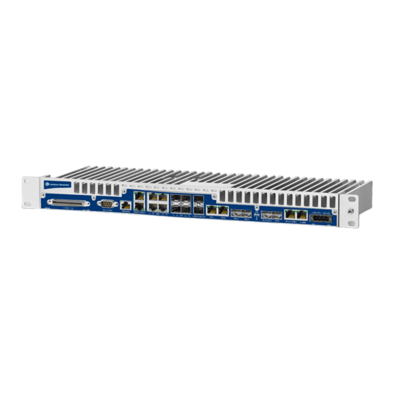
Chapter 1: Introduction System Overview System Overview This section provides a brief overview of the PTP 820 systems described in this document. A separate Technical Description is available for each product, providing a full description of the individual system and its specifications PTP 820F PTP 820F is a split-mount edge node that delivers multi-Gbps radio capacity to the transport network. -
Page 51: Assured Platform
Chapter 1: Introduction System Overview 2x FE electrical interfaces (RJ-45) • External alarms interface PTP 820G is based on a passive cooling design that does not require fans, for improved operational efficiency. A PTP 820G consists of an indoor unit (IDU) and one or two radio frequency units (RFUs). PTP 820G can be used with RFU-C, 1500HP/RFU-HP, and RFU-A. -
Page 52: Ptp 820F Idu Hardware Architecture
Chapter 1: Introduction PTP 820F IDU Hardware Architecture PTP 820F IDU Hardware Architecture PTP 820F is a compact unit that fits in a single rack unit, with a passive cooling system that eliminates the need for fans. A PTP 820F system consists of an PTP 820F indoor unit (IDU) and up to three radio frequency units (RFUs). The IDU is connected to each RFU via CAT-5e or CAT-6/6a cables or optical fibers. -
Page 53: Front Panel Description
Chapter 1: Introduction Front Panel Description Front Panel Description This section describes thePTP 820F’s front panel. The following sections provide detailed descriptions of the PTP 820F’s interfaces and LEDs. Figure 1 PTP 820F Front Panel and Interface Table 1 PTP 820F Interfaces Interface For Further Information 16 x E1s... -
Page 54: Ethernet Traffic Interfaces
Chapter 1: Introduction Front Panel Description Ethernet Traffic interfaces The front panel of the PTP 820F contains 4 x GbE combo interfaces (electrical or optical) for Ethernet traffic. These interfaces are numbered as shown in the following figure. Figure 2 GbE Combo Interface Numbering GbE 1/SFP 1 and GbE 2/SFP 2 can be configured as normal Ethernet traffic interfaces or as cascading interfaces. -
Page 55: E1/Ds1 Interface
Chapter 1: Introduction Front Panel Description Figure 4 Management Interface Pin Connections RJ-45 Connector Management Switch (female) Port 1 Port 2 If the user only needs to use a single management interface, a standard Cat5 RJ-45 cable (straight or cross) can be connected to the MGMT interface. -
Page 56: Synchronization Interface
Chapter 1: Introduction Front Panel Description The allowed power input range for the PTP 820F is -40V to -60V. An under voltage alarm is triggered if the power goes below the allowed range, and an over voltage alarm is triggered if the power goes above the allowed range. Synchronization Interface PTP 820F includes an RJ-45 synchronization interface for T3 clock input and T4 clock output. -
Page 57: Figure 5 Sm Card And Cover
Chapter 1: Introduction Front Panel Description Figure 5 SM Card and Cover phn-3965_006v002 Page 1-11... -
Page 58: Ptp 820G Idu Hardware Architecture
Chapter 1: Introduction PTP 820G IDU Hardware Architecture PTP 820G IDU Hardware Architecture PTP 820G is a compact unit that fits in a single rack unit, with a passive cooling system that eliminates the need for fans. A PTP 820G system consists of a PTP 820G indoor unit (IDU) and one or two radio frequency units (RFUs). A coaxial cable connects the IDU to each RFU, transmits traffic and management data between the IDU and the RFU, and provides -48V DC power to the RFU. -
Page 59: Front Panel Description
Chapter 1: Introduction Front Panel Description Front Panel Description This section describes the PTP 820G front panel. The following sections provide detailed descriptions of the PTP 820G interfaces and LEDs. Figure 6 PTP 820G Front Panel and Interfaces TDM Sync Interface In/Out (RJ 45) Table 3 PTP 820 Interfaces... -
Page 60: Ethernet Traffic Interfaces
Chapter 1: Introduction Front Panel Description Ethernet Traffic Interfaces The front panel of the PTP 820G contains four electrical and two optical GbE Ethernet traffic interfaces: • 2 x GbE dual mode electrical or cascading interfaces (RJ-45) – GbE1/CS1, GbE2/CS2 •... -
Page 61: E1/Ds1 Interface (Optional)
Chapter 1: Introduction Front Panel Description E1/DS1 Interface (Optional) Optionally, PTP 820G can be ordered with an MDR69 connector in which 16 E1/DS1 interfaces are available (ports 1 through 16). Radio Interfaces PTP 820G includes one or two radio interfaces, depending on the hardware assembly option that was selected. Each radio interface uses a TNC connector type. -
Page 62: External Alarms
Chapter 1: Introduction Front Panel Description External Alarms PTP 820G includes a DB9 dry contact external alarms interface. The external alarms interface supports five input alarms and a single output alarm. The input alarms are configurable according to: Intermediate Critical Major Minor Warning... -
Page 63: Rfu Overview
Chapter 1: Introduction RFU Overview RFU Overview Radio Frequency Units (RFUs) were designed with sturdiness, power, simplicity, and compatibility in mind. These advanced systems provide high-power transmission for short and long distances and can be assembled and installed quickly and easily. -
Page 64: Idu-Rfu Connection And Power Supply For Ptp 820F
Chapter 1: Introduction RFU Overview IDU-RFU Connection and Power Supply for PTP 820F An RFU-D, RFU-D-HP, RFU-E, and RFU-S can be connected to anPTP 820F via a standard CAT-5e or preferably CAT- 6/6a cable, with RJ-45 connectors on the RFU and an RJ-45 connector on thePTP 820F. They can also be connected to the PTP 820F over optical fiber cables via the optical (SFP) RFU connection on the PTP 820F. -
Page 65: Idu-Rfu Connection And Power Supply For Ptp 820G
Chapter 1: Introduction RFU Overview IDU-RFU Connection and Power Supply for PTP 820G RFU-C, RFU-HP/1500HP, and RFU-A RFUs are connected to the IDU by a coaxial cable RG-223 (up to 100 m/300 ft), Belden 9914/RG-8 (up to 300 m/1000 ft) or equivalent, with an N-type connector (male) on the RFU and a TNC connector on thePTP 820. -
Page 66: The Web-Based Element Management System
Chapter 1: Introduction The Web-Based Element Management System The Web-Based Element Management System This section includes: • Introduction to the Web EMS • Web EMS Page Layout • The Unit Summary Page • The Radio Summary Page Introduction to the Web EMS The Element Management System (Web EMS) is an HTTP web-based element manager that enables the operator to perform configuration operations and obtain statistical and performance information related to the system, including:... -
Page 67: Figure 8 Main Web Ems Page
Chapter 1: Introduction The Web-Based Element Management System • The main section of the page provides the page's basic functionality. Figure 8 Main Web EMS Page Front Panel Representation Optionally, you can display a representation of the PTP 820G front panel by clicking either the arrow in the center or the arrow at the right of the bottom toolbar. -
Page 68: Figure 10 Main Web Ems Page With Representation Of The Front Panel- Ptp 820F
Chapter 1: Introduction The Web-Based Element Management System Figure 10 Main Web EMS Page with Representation of the Front Panel- PTP 820F Figure 11 Main Web EMS Page with Representation of the Front Panel- PTP 820G Related Pages Drop-Down List Certain pages include a Related Pages drop-down list on the upper right of the main section of the page. -
Page 69: Figure 12 Related Pages Drop-Down List
Chapter 1: Introduction The Web-Based Element Management System Figure 12 Related Pages Drop-Down List phn-3965_006v002 Page 1-23... -
Page 70: The Unit Summary Page
Chapter 1: Introduction The Web-Based Element Management System The Unit Summary Page The Unit Summary page is the first page that appears when you log into the Web EMS. It gathers the unit parameters, current alarms, and unit inventory information on a single page for quick viewing. Figure 13 Unit Summary Page The Unit Summary page includes: •... -
Page 71: The Radio Summary Page
Chapter 1: Introduction The Web-Based Element Management System Figure 14 Unit Summary Page – Customizing collumns The Radio Summary Page The Radio Summary page gathers the key link and radio parameters on a single page for quick viewing. To display the Radio Summary page, select Radio Summary from the Web EMS main menu. - Page 72 Chapter 1: Introduction The Web-Based Element Management System • Radio Receiver – Receiver PMs and statistics, including defective blocks, modem MSE, and RX level, modulation, and bit rate. For additional information, see Configuring the Radio Parameters Entering Radio View (CLI) •...
- Page 73 Chapter 1: Introduction The Web-Based Element Management System Muting and Unmuting the Radio (CLI) To mute or unmute the radio, enter the following command in radio view: radio[x/x]>rf mute set admin <admin> To configure a timed mute, enter the following command in radio view: radio[x/x]>...
- Page 74 Chapter 1: Introduction The Web-Based Element Management System Table 22: Transmit (TX) Frequency CLI Parameters Parameter Input Permitted Description Type Values tx-frequency Number Depends on The desired TX frequency (in KHz) and, if the MRMC <local-remote> is set to enable, the desired script and RX frequency of the remote unit.
-
Page 75: Figure 16 Unit & Radio Summary Page - Customizing Columns
Chapter 1: Introduction The Web-Based Element Management System Note When one or more columns are hidden, the icon turns white ( ). Figure 16 Unit & Radio Summary Page – Customizing Columns phn-3965_006v002 Page 1-29... -
Page 76: Reference Guide To Web Ems Menu Structure
Chapter 1: Introduction Reference Guide to Web EMS Menu Structure Reference Guide to Web EMS Menu Structure The following table shows the Web EMS menu hierarchy, with links to the sections in this document that provide instructions for the relevant menu item. Note Some menu items are only available if the relevant activation key or feature is enabled. - Page 77 Chapter 1: Introduction Reference Guide to Web EMS Menu Structure Sub-Menus For Further Information Management > Unit Parameters Configuring Unit Parameters. Management > NTP Configuration Configuring NTP Management > Time Services Setting the Time and Date (Optional) Management > Interface Manager Enabling the Interfaces (Interface Manager) Management >...
- Page 78 Chapter 1: Introduction Reference Guide to Web EMS Menu Structure Security > X.509 Certificate > Download & Install Configuring X.509 CSR Certificates and HTTPS Security > Access Control > General Configuring the General Access Control Parameters Security > Access Control > User Profiles Configuring User Profiles Security >...
-
Page 79: Table 7 Web Ems Menu Hierarchy - Faults Menu
Chapter 1: Introduction Reference Guide to Web EMS Menu Structure Table 7 Web EMS Menu Hierarchy – Faults Menu Sub-Menus For Further Information Current Alarms Viewing Current Alarms Alarm Statistics Viewing Alarm Statistics Event Log Viewing the Event Log Alarm Configuration Editing Alarm Text and Severity Table 8 Web EMS Menu Hierarchy –... -
Page 80: Table 9 Web Ems Menu Hierarchy - Radio Menu
Chapter 1: Introduction Reference Guide to Web EMS Menu Structure TDM PseudoWire > Advanced > PM > Service Displaying Pseudowire Service PMs TDM > Interfaces > E1/DS1 Configuring the E1/DS1 Parameters (CLI). TDM > Diagnostics > PDH Loopback Performing Loopback on E1/DS1s TDM >... - Page 81 Chapter 1: Introduction Reference Guide to Web EMS Menu Structure radio[1/1]> The following command enters radio view for fixed radio interface 2: root> radio slot 1 port 2 The following prompt appears: radio[1/2]> The following command enters radio view for an RMC in expansion slot 3: root>...
- Page 82 Chapter 1: Introduction Reference Guide to Web EMS Menu Structure The following command mutes the RMC in expansion slot 2: radio[2/1]>rf mute set admin on The following command configures a timed mute on fixed radio interface 1. This mute will automatically expire in 30 minutes.
- Page 83 Chapter 1: Introduction Reference Guide to Web EMS Menu Structure radio[1/2]>rf set rx-frequency 12900000 local-remote disable Configuring the Transmit (TX) Level (CLI) To set the transmit (TX) level of a radio, enter the following command in radio view: radio[x/x]>rf set tx-level <tx-level> To display the maximum transmit (TX) level of a radio, enter the following command in radio view: radio[x/x]>rf show max-tx-level...
- Page 84 Chapter 1: Introduction Reference Guide to Web EMS Menu Structure Muting and Unmuting the Radio (CLI) To mute or unmute the radio, enter the following command in radio view: radio[x/x]>rf mute set admin <admin> To configure a timed mute, enter the following command in radio view: radio[x/x]>...
- Page 85 Chapter 1: Introduction Reference Guide to Web EMS Menu Structure Configuring the Transmit (TX) Frequency (CLI) To set the transmit (TX) frequency of a radio, enter the following command in radio view. This command automatically sets the remote RX frequency in parallel, unless you set the local- remote attribute to disable: radio[x/x]>rf set tx-frequency <tx-frequency>...
- Page 86 Chapter 1: Introduction Reference Guide to Web EMS Menu Structure radio[x/x]>rf show max-tx-level Table: Transmit (TX) Level CLI Parameters Paramet Input Permitted Description Values tx-level Number -50-34 The desired TX signal level (TSL), in dBm. The following command sets the TX level of fixed radio interface 1 to 10 dBm: radio[1/1]>rf set tx-level 10 Configuring the Radio (MRMC) Script(s) MRMC >...
-
Page 87: Table 10 Ptp 820G Web Ems Menu Hierarchy - Ethernet Menu
Chapter 1: Introduction Reference Guide to Web EMS Menu Structure Frame error rate Diagnostics > Performing Radio Loopback Loopback Groups > Radio Configuring HSB Radio Protection Protection (PTP 820G only) Groups > XPIC Configuring XPIC Groups > Multi Configuring Multi-Carrier ABC Carrier ABC Table 10 PTP 820G Web EMS Menu Hierarchy –... - Page 88 Chapter 1: Introduction Reference Guide to Web EMS Menu Structure Sub-Menus For Further Information Interfaces > Groups > LAG Configuring Link Aggregation (LAG) and LACP. PM & Statistics > RMON RMON Statistics PM & Statistics > Egress CoS Statistics Egress CoS Statistics PM &...
- Page 89 Chapter 1: Introduction Reference Guide to Web EMS Menu Structure Sub-Menus For Further Information Protocols > MSTP > Bridge > VLAN Viewing the MSTP VLAN Parameters Protocols > MSTP > Port > Spanning Tree Viewing and Configuring the MSTP Port Spanning Tree Protocols >...
-
Page 90: Table 11 Ptp 820G Web Ems Menu Hierarchy - Cascading Menu
Chapter 1: Introduction Reference Guide to Web EMS Menu Structure Sub-Menus For Further Information Protocols > LACP > Aggregation Displaying LACP Aggregation Status Parameters Protocols > LACP > Port > Status Displaying LACP Port Status Parameters Protocols > LACP > Port > Statistics Displaying LACP Port Statistics Protocols >... - Page 91 Chapter 1: Introduction Reference Guide to Web EMS Menu Structure Sub-Menus For Further Information phn-3965_006v002 Page 1-45...
- Page 92 Chapter 1: Introduction Reference Guide to Web EMS Menu Structure Interfaces Configuring RFU3/SFP5,RFU3/2.5GE5 as an Ethernet or RFU Interface(PTP 820F only) On PTP 820F, the combo port labelled RFU3/SFP5 (SFP) and RFU3/2.5GE5 (RJ-45) can be configured as either an RFU interface (RFU3) or an Ethernet interface (Eth3).
- Page 93 Chapter 1: Introduction Reference Guide to Web EMS Menu Structure Figure: RFU/Ethernet Interface Configuration Page Select Radio Unit: Slot 1, Port 3 and click Edit. The RFU/Ethernet Interface Configuration – Edit page opens. Figure: RFU/Ethernet Interface Configuration – Edit Page In the Interface Type field, select RFU or Ethernet.
-
Page 94: Table 12 Ptp 820G Web Ems Menu Hierarchy - Sync Menu
Chapter 1: Introduction Reference Guide to Web EMS Menu Structure Sub-Menus For Further Information If you configured the port as an Ethernet interface, you must set the port’s admin state to Up in the Interface Manager. See Enabling the Interfaces (Interface Manager). -
Page 95: Table 13 Web Ems Menu Hierarchy - Quick Configuration Menu
Chapter 1: Introduction Reference Guide to Web EMS Menu Structure 1588 > Boundary Clock > Port Statistics Configuring 1588 Boundary Clock Table 13 Web EMS Menu Hierarchy – Quick Configuration Menu Sub-Menus For Further Information PIPE > Single Carrier > 1+0 Configuring a 1+0 Link Using the Quick Configuration Wizard PIPE >... -
Page 96: Chapter 2: Getting Started
Chapter 2: Getting Started This section includes: • Assigning IP Addresses in the Network • Establishing a Connection • Logging On • Changing Your Password • Performing Quick Platform Setup • Configuring In-Band Management • Changing the Management IP Address •... - Page 97 Chapter 2: Getting Started Reference Guide to Web EMS Menu Structure On PTP 820F, the combo port labelled RFU3/SFP5 (SFP) and RFU3/2.5GE5 (RJ-45) can be configured as either an RFU interface (RFU3) or an Ethernet interface (Eth3). By default, this port is an RFU interface. Figure: RFU3/SFP5 and RFU3/2.5GE5 Combo Port To change the port’s use from RFU to Ethernet or Ethernet to RFU: Set the port’s admin state to Down in the Interface Manager.
- Page 98 Chapter 2: Getting Started Reference Guide to Web EMS Menu Structure Figure: RFU/Ethernet Interface Configuration Page Select Radio Unit: Slot 1, Port 3 and click Edit. The RFU/Ethernet Interface Configuration – Edit page opens. Figure: RFU/Ethernet Interface Configuration – Edit Page In the Interface Type field, select RFU or Ethernet.
- Page 99 Chapter 2: Getting Started Reference Guide to Web EMS Menu Structure • Port speed: 1 GE • Media Type: RJ45 • Auto Negotiation: On To change these parameters, go to the Physical Interfaces page. See Configuring Ethernet Interfaces. Note: Both Eth5 and Eth6 can be configured to either 1 GE or 2.5 GE. The other PTP 820F Ethernet ports support 1 GE only.
- Page 100 Chapter 2: Getting Started Reference Guide to Web EMS Menu Structure Muting and Unmuting the Radio (CLI) To mute or unmute the radio, enter the following command in radio view: radio[x/x]>rf mute set admin <admin> To configure a timed mute, enter the following command in radio view: radio[x/x]>...
- Page 101 Chapter 2: Getting Started Reference Guide to Web EMS Menu Structure Table 22: Transmit (TX) Frequency CLI Parameters Parameter Input Permitted Description Type Values tx-frequency Number Depends on The desired TX frequency (in KHz) and, if the MRMC <local-remote> is set to enable, the desired script and RX frequency of the remote unit.
-
Page 102: Assigning Ip Addresses In The Network
Chapter 2: Getting Started Assigning IP Addresses in the Network Assigning IP Addresses in the Network Before connection over the radio hop is established, it is of high importance that you assign each network element a dedicated IP address, according to an IP plan for the total network. See Changing the Management IP Address. -
Page 103: Establishing A Connection
Chapter 2: Getting Started Establishing a Connection Establishing a Connection You can connect to the PTP 820G or PTP 820F unit via a serial or a LAN connection. Connecting to the Unit with a Serial Connection Connect a serial RS-232 cable with an RJ-45 interface from the laptop or PC you are using to configure the unit, to the Terminal Interface on the front panel. -
Page 104: Connecting To The Unit With A Lan Connection
Chapter 2: Getting Started Establishing a Connection Connecting to the Unit with a LAN Connection PTP 820G and PTP 820F contain two FE management interfaces, which connect to a single RJ-45 physical connector on the front panel (MGMT). For details on which type of cable to use to utilize either one or both management interfaces, see Ethernet Management Interfaces. - Page 105 Chapter 2: Getting Started Establishing a Connection Select Local Area Connection > Properties> Internet Protocol Version 4 (TCP/IP) and set the following parameters: IP address: 192.168.1.10 Subnet mask 255.255.255.0 No default gateway Click OK to apply the settings. phn-3965_006v002 Page 2-10...
-
Page 106: Logging On
Chapter 2: Getting Started Logging On Logging On Open an Internet browser (Internet Explorer, Mozilla Firefox, or Google Chrome). Enter the default IP address "192.168.1.1" in the Address Bar. The Login page opens. Figure 21 Login Page Enter the following values: User Name: admin Password: admin Click Apply. -
Page 107: Changing Your Password
In addition to the Admin password, there is an additional password protected user account, “root user”, which is configured in the system. The root user password and instructions for changing this password are available from Cambium Networks Customer Support. It is strongly recommended to change this password. To change your password: 1. -
Page 108: Performing Quick Platform Setup
Chapter 2: Getting Started Performing Quick Platform Setup Performing Quick Platform Setup The Platform Setup page in the Web EMS centralizes the main configurable items from several Web EMS pages in a single location: • Unit Parameters (Name, Contact Person, Location, Longitude, and Latitude) •... -
Page 109: Figure 23 Quick Configuration - Platform Setup Page
Chapter 2: Getting Started Performing Quick Platform Setup Figure 23 Quick Configuration – Platform Setup Page 2. The Unit Parameters section is optional. For details on each field, see Configuring Unit Parameters. 3. In the IPv4 Address section, configure the unit’s management IP address, subnet mask, and, optionally, a default gateway. - Page 110 Chapter 2: Getting Started Performing Quick Platform Setup 5. In the Activation Key section, you can enable or disable Demo mode in the Demo admin field. Demo mode enables all features for 60 days. When demo mode expires, the most recent valid activation key goes into effect.
-
Page 111: Figure 24 Quick Configuration - Platform Setup Summary Page
Chapter 2: Getting Started Performing Quick Platform Setup Figure 24 Quick Configuration – Platform Setup Summary Page phn-3965_006v002 Page 2-16... -
Page 112: Configuring In-Band Management
Chapter 2: Getting Started Configuring In-Band Management Configuring In-Band Management You can configure in-band management in order to manage the unit remotely via its radio and/or Ethernet interfaces. Each PTP 820G or PTP 820F unit includes a pre-defined management service with Service ID 1025. The management service is a multipoint service that connects the two local management ports and the network element host CPU in a single service. -
Page 113: Changing The Management Ip Address
Chapter 2: Getting Started Changing the Management IP Address Changing the Management IP Address Related Topics: • Defining the IP Protocol Version for Initiating Communications • Configuring the Remote Unit’s IP Address To change the management IP address of the local unit: Select Platform >... - Page 114 Chapter 2: Getting Started Changing the Management IP Address Click Apply. phn-3965_006v002 Page 2-19...
-
Page 115: Configuring Unit Redundancy For The Ptp 820G
Chapter 2: Getting Started Configuring Unit Redundancy for the PTP 820G Configuring Unit Redundancy for the PTP 820G This section explains how to configure unit redundancy for the PTP 820G, and includes the following topics: • Unit Redundancy Overview • Configuring Unit Redundancy •... -
Page 116: Configuring Unit Redundancy
Chapter 2: Getting Started Configuring Unit Redundancy for the PTP 820G Note • The external switch must support LACP. PTP 820G supports LACP for purposes of line protection only. PTP 820G supports a special LACP implementation for purposes of line protection only. This LACP implementation is configured on the logical interface level, as described in Configuring Ethernet Interface Protection. - Page 117 Chapter 2: Getting Started Configuring Unit Redundancy for the PTP 820G Configure the unit that will be the active unit so that it will have a working radio link by performing all necessary radio configurations, such as configuring the MRMC scripts, setting the frequency, unmuting the radio, and setting up radio groups such as XPIC or Multi-Carrier ABC (Multi-Radio).
-
Page 118: Cabling Requirements For Unit Redundancy
Chapter 2: Getting Started Configuring Unit Redundancy for the PTP 820G Cabling Requirements for Unit Redundancy Cabling for Ethernet Interfaces For Ethernet Splitter Mode, the following Y-cable must be connected to the relevant interfaces on the active and standby units: Table 15 Y-Cable for Electrical Splitter Mode FE Traffic Interface Protection Part Number Description... -
Page 119: Configuring Ethernet Interface Protection
Chapter 2: Getting Started Configuring Unit Redundancy for the PTP 820G Figure 26 PTP 820G with Unit Redundancy – Protection and Management Splitter Connection PTP 820G Management Port (MGMT) External Management Connection PTP 820G Management Port (MGMT) The local management connection uses PTP 820G management interface 1. The LED on the upper left of the MGMT port is Green when the interface is enabled and the link is operational. -
Page 120: Enabling Unit Redundancy
Chapter 2: Getting Started Configuring Unit Redundancy for the PTP 820G Figure 27 Logical Interfaces – Edit Page iii. In the Interface Mode field, select LACP. Click Apply, then Close. Reset the unit. See Performing a Hard (Cold) Reset (CLI). Note Because a unit reset is required when changing the Interface Mode to or from LACP, it is recommended to perform copy-to-mate immediately after changing the Interface Mode to or from... -
Page 121: Figure 28 Unit Redundancy Page
Chapter 2: Getting Started Configuring Unit Redundancy for the PTP 820G Figure 28 Unit Redundancy Page 2. In the Protection Admin field, select Enable. 3. Click Apply. The system configures itself for unit redundancy: • The system determines which unit is the Active unit based on a number of pre-defined criteria. To see which unit is the active unit, look at the traffic interface LEDs;... -
Page 122: Changing The Configuration After Enabling Unit Redundancy
Chapter 2: Getting Started Configuring Unit Redundancy for the PTP 820G • Active – Enables you to configure the Active unit. • Standby – In most cases, this tab is read-only and enables you to display Standby unit parameters. Even when a switchover occurs, the unit displayed in the Web EMS is always the currently Active unit. -
Page 123: Viewing Link And Protection Status And Activity
Chapter 2: Getting Started Configuring Unit Redundancy for the PTP 820G Figure 29 Standby Tab of Unit Redundancy Page Viewing Link and Protection Status and Activity You can view link and protection status and activity any time. To view link and protection status and activity: Select Platform >... -
Page 124: Performing Lockout
Chapter 2: Getting Started Configuring Unit Redundancy for the PTP 820G 3. Lockout 4. Radio Loss of Frame (LOF) on active unit 5. Change request from the remote unit. This takes place in the event of radio LOF on both units; a change request is sent to the active unit on the other side of the link. - Page 125 Chapter 2: Getting Started Configuring Unit Redundancy for the PTP 820G 2. Change the IP address of the active remote unit. 3. Disable all active traffic interfaces on the active remote unit. This should be performed in a single action by selecting all of the relevant interfaces in the Interface Manager page and selecting Down >...
-
Page 126: Determining Etsi Or Ansi (Fcc) Tdm Mode
Chapter 2: Getting Started Determining ETSI or ANSI (FCC) TDM Mode Determining ETSI or ANSI (FCC) TDM Mode By default, the TDM interfaces in a PTP 820G or PTP 820F unit are set to operate according to the ETSI standard, in E1 mode. -
Page 127: Configuring The Activation Key
Chapter 2: Getting Started Configuring the Activation Key Configuring the Activation Key PTP 820G and PTP 820F offers a pay as-you-grow concept in which future capacity growth and additional functionality can be enabled with activation keys. For purposes of the activation keys, each PTP 820G/F unit is considered a distinct device. -
Page 128: Figure 30 Activation Key Configuration Page
Chapter 2: Getting Started Configuring the Activation Key Figure 30 Activation Key Configuration Page Table 18 Activation Key Status Parameters Parameter Definition Type Displays the current activation key type. Validation number Displays a random, system-generated validation number. Date code Displays a date code used for validation of the current activation key cipher. -
Page 129: Entering The Activation Key
Chapter 2: Getting Started Configuring the Activation Key Entering the Activation Key To enter a new activation key: Select Platform > Activation Key > Activation Key Configuration. The Activation Key Configuration page opens (Figure 30). Enter the activation key cipher you have received from the vendor in the Activation Key field. The activation key cipher is a string that enables all features and capacities that have been purchased for the unit. -
Page 130: Table 19 Activation Key Status Parameters
Chapter 2: Getting Started Configuring the Activation Key Note Some of the features listed in the Activation Key Overview page may not be supported in the currently installed software version. Table 19 Activation Key Status Parameters Parameter Definition Feature ID A unique ID that identifies the feature. -
Page 131: Setting The Time And Date (Optional)
Chapter 2: Getting Started Setting the Time and Date (Optional) Setting the Time and Date (Optional) Related Topics: • Configuring NTP PTP 820G/F uses the Universal Time Coordinated (UTC) standard for time and date configuration. UTC is a more updated and accurate method of date coordination than the earlier date standard, Greenwich Mean Time (GMT). Every PTP 820G/F unit holds the UTC offset and daylight savings time information for the location of the unit. -
Page 132: Table 20 Time Services Parameters
Chapter 2: Getting Started Setting the Time and Date (Optional) Table 20 Time Services Parameters Parameter Definition UTC date and The UTC date and time. time Date and Time Local date and The calculated local date and time, based on the local clock, Configuration time Universal Time Coordinated (UTC), and Daylight Savings Time... -
Page 133: Enabling The Interfaces (Interface Manager)
Chapter 2: Getting Started Enabling the Interfaces (Interface Manager) Enabling the Interfaces (Interface Manager) The following are the default settings for fixed interfaces on PTP 820G and PTP 820F unit's: • Ethernet traffic interfaces, the second management interface, and the Synchronization interface are disabled, and must be manually enabled as described below. -
Page 134: Figure 34 Interface Manager Page - Ptp 820G
Chapter 2: Getting Started Enabling the Interfaces (Interface Manager) Figure 34 Interface Manager Page – PTP 820G To enable or disable an individual interface: Select the interface in the Interface Manager table. Click Edit. The Interface Manager – Edit page opens. Figure 35 Interface Manager –... -
Page 135: Enabling The Second Management Interface
Chapter 2: Getting Started Configuring RFU3/SFP5,RFU3/2.5GE5 as an Ethernet or RFU Interface(PTP 820F only) Figure 36 Multiple Selection Operation Section (Interface Manager Page) Click Apply. Note The Operational Status field displays the current, actual operational state of the interface (Up or Down). - Page 136 Chapter 2: Getting Started Configuring RFU3/SFP5,RFU3/2.5GE5 as an Ethernet or RFU Interface(PTP 820F only) On PTP 820F, the combo port labelled RFU3/SFP5 (SFP) and RFU3/2.5GE5 (RJ-45) can be configured as either an RFU interface (RFU3) or an Ethernet interface (Eth3). By default, this port is an RFU interface. Figure: RFU3/SFP5 and RFU3/2.5GE5 Combo Port To change the port’s use from RFU to Ethernet or Ethernet to RFU: Set the port’s admin state to Down in the Interface Manager.
- Page 137 Chapter 2: Getting Started Configuring RFU3/SFP5,RFU3/2.5GE5 as an Ethernet or RFU Interface(PTP 820F only) Figure: RFU/Ethernet Interface Configuration Page Select Radio Unit: Slot 1, Port 3 and click Edit. The RFU/Ethernet Interface Configuration – Edit page opens. Figure: RFU/Ethernet Interface Configuration – Edit Page In the Interface Type field, select RFU or Ethernet.
-
Page 138: Configuring Cascading Interfaces (Optional)
Chapter 2: Getting Started Configuring Cascading Interfaces (Optional) • Port speed: 1 GE • Media Type: RJ45 • Auto Negotiation: On To change these parameters, go to the Physical Interfaces page. See Configuring Ethernet Interfaces. Note: Both Eth5 and Eth6 can be configured to either 1 GE or 2.5 GE. The other PTP 820F Ethernet ports support 1 GE only. - Page 139 Chapter 2: Getting Started Configuring Cascading Interfaces (Optional) In the Interface Type field, select Cascading. Click Apply, then Close. Note You cannot change the status of an interface (Cascading or Ethernet) if a service point is configured on the interface. You cannot change the status of an interface (Cascading or Ethernet) if the interface belongs to a LAG.
-
Page 140: Configuring The Radio Parameters
Chapter 2: Getting Started Configuring the Radio Parameters Configuring the Radio Parameters In order to establish a radio link, you must: • Unmute the radio carrier. • Configure the radio frequencies. • Configure the TX level. You can do these tasks, perform other radio configuration tasks, and display the radio parameters in the Radio Parameters page. -
Page 141: Figure 40 Radio Parameters Configuration Page
Chapter 2: Getting Started Configuring the Radio Parameters Figure 40 Radio Parameters Configuration Page Set the radio frequency in the Frequency control (Local) section: In the TX Frequency (MHz) field, set the transmission radio frequency in MHz. In the RX Frequency (MHz) field, set the received radio frequency in MHz. Click Apply. -
Page 142: Enabling Link Id Mismatch Security
Chapter 2: Getting Started Configuring the Radio Parameters In the Link ID field, enter a unique link identifier from 1 to 65535. The Link ID identifies the link, in order to distinguish it from other links. If the Link ID is not the same at both sides of the link, a Link ID Mismatch alarm is raised. - Page 143 Chapter 2: Getting Started Entering Radio View (CLI) Entering Radio View (CLI) To view and configure radio parameters, you must first enter the radio’s view level in the CLI. Use the following command to enter a radio’s view level: root> radio slot <slot> port <port> The following command enters radio view for fixed radio interface 1: root>...
- Page 144 Chapter 2: Getting Started Entering Radio View (CLI) Muting and Unmuting the Radio (CLI) To mute or unmute the radio, enter the following command in radio view: radio[x/x]>rf mute set admin <admin> To configure a timed mute, enter the following command in radio view: radio[x/x]>...
- Page 145 Chapter 2: Getting Started Entering Radio View (CLI) Table 22: Transmit (TX) Frequency CLI Parameters Parameter Input Permitted Description Type Values tx-frequency Number Depends on The desired TX frequency (in KHz) and, if the MRMC <local-remote> is set to enable, the desired script and RX frequency of the remote unit.
-
Page 146: Configuring The Radio (Mrmc) Script(S)
Chapter 2: Getting Started Configuring the Radio (MRMC) Script(s) Configuring the Radio (MRMC) Script(s) Related Topics: • Displaying MRMC Status Multi-Rate Multi-Constellation (MRMC) radio scripts define how the radio utilizes its available capacity. Each script is a pre-defined collection of configuration settings that specify the radio’s transmit and receive levels, link modulation, channel spacing, and bit rate. - Page 147 Chapter 2: Getting Started Configuring the Radio (MRMC) Script(s) Figure 42 MRMC Symmetrical Scripts Page (ETSI) – PTP 820G Figure 43 MRMC Symmetrical Scripts Page (ANSI) In the Select Radio Interface field, select the slot for which you want to configure the script. Select the script you want to assign to the radio.
- Page 148 Chapter 2: Getting Started Configuring the Radio (MRMC) Script(s) Figure 44 MRMC Symmetrical Scripts Page (Configuration) – PTP 820F Figure 45 MRMC Symmetrical Scripts Page (Configuration) - PTP 820G In the MRMC Script operational mode field, select the ACM mode: Fixed or Adaptive. phn-3965_006v002 Page 2-53...
- Page 149 Chapter 2: Getting Started Configuring the Radio (MRMC) Script(s) Fixed ACM mode applies constant TX and RX rates. However, unlike regular scripts, with a Fixed ACM script you can specify a maximum profile to inhibit inefficient transmission levels. In Adaptive ACM mode, TX and RX rates are dynamic. An ACM-enabled radio system automatically chooses which profile to use according to the channel fading conditions.
- Page 150 Chapter 2: Getting Started Configuring the Radio (MRMC) Script(s) Figure 47 MRMC Symmetrical Scripts Page (Configuration – Adaptive Mode) PTP 820G Define the script profile or profiles: If you selected Fixed ACM mode, select the ACM profile in the MRMC Script profile field. If you selected Adaptive ACM mode, select the maximum and minimum ACM profiles in the MRMC Script maximum profile and the MRMC Script minimum profile fields.
- Page 151 Chapter 2: Getting Started Configuring the Radio (MRMC) Script(s) Table 23 PTP 820G Radio Profiles for Fixed Interfces and RMC-B Profile Modulation Profile 0 4 QAM Profile 1 8 QAM Profile 2 16 QAM Profile 3 32 QAM Profile 4 64 QAM Profile 5 128 QAM...
- Page 152 Chapter 2: Getting Started Configuring the Radio (MRMC) Script(s) Table 25 PTP 820F Radio Profiles for RFU-E Profile Modulation Profile 0 BPSK Profile 1 QPSK Profile 2 8 PSK Profile 3 16 QAM Profile 4 32 QAM Profile 5 64 QAM Profile 6 128 QAM Profile 7...
- Page 153 Chapter 2: Getting Started Configuring the Radio (MRMC) Script(s) Profile Modulation The ACM mode: Fixed or Adaptive. MRMC Script operational mode • Fixed ACM mode applies constant TX and RX rates. However, unlike regular scripts, with a Fixed ACM script you can specify a maximum profile to inhibit inefficient transmission levels.
-
Page 154: Enabling Acm With Adaptive Transmit Power
Chapter 2: Getting Started Enabling ACM with Adaptive Transmit Power Enabling ACM with Adaptive Transmit Power This feature requires: • ACM script • When working with RFU-C, requires RFU software version 2.17 or above When planning ACM-based radio links, the radio planner attempts to apply the lowest transmit power that will perform satisfactorily at the highest level of modulation. -
Page 155: Operating In Fips Mode
These labels must be replaced whenever components are added to or removed from the unit. Replacement labels can be ordered from Cambium Networks. Tamper-evident labels should be inspected for integrity at least once every six months. For further details, refer to the PTP 820G Installation Guide. - Page 156 Chapter 2: Getting Started Operating in FIPS Mode Figure 48 Security General Configuration Page In the FIPS admin configuration field, select Enable. Click Apply. Note Changing the FIPS configuration causes a unit reset.. After enabling FIPS: • The MD5 option for SNMPv3 is blocked. •...
-
Page 157: Configuring Grouping (Optional)
Chapter 2: Getting Started Configuring Grouping (Optional) Configuring Grouping (Optional) At this point in the configuration process, you should configure any interface groups that need to be set up according to your network plan. For details on available grouping and other configuration options, as well as configuration instructions, see System Configurations. -
Page 158: Creating Service(S) For Traffic
Chapter 2: Getting Started Creating Service(s) for Traffic Creating Service(s) for Traffic In order to pass traffic through the PTP 820G, and PTP 820F you must configure Ethernet and/or TDM traffic services. For configuration instructions, see: • Configuring Ethernet Service(s) •... -
Page 159: Chapter 3: Configuration Guide
Chapter 3: Configuration Guide This section includes: • System Configurations • Configuring a 1+0 Link • Configuring Multi-Carrier ABC • Configuring Link Aggregation (LAG) • Configuring XPIC • Configuring HSB Radio Protection phn-3965_006v002 Page 3-1... -
Page 160: System Configurations
Chapter 3: Configuration Guide System Configurations System Configurations This section lists basic system configurations and their prerequisites, with links to configuration instructions. This section includes: • Radio Configurations • TDM Configurations Note For an up-to-date description of feature and configuration limitations, refer to the Release Notes for version 10.0 Radio Configurations A PTP 820G or PTP 820F system can be used in the following radio configurations. -
Page 161: Tdm Configurations
Chapter 3: Configuration Guide System Configurations Configuring a 1+0 Link Configuring a Link Using the Quick Configuration Wizard 1+0 IF Combining Requires 1500HP Configuring IF Combining 2+0 Single Polarization Requires Multi-Carrier Configuring Multi-Carrier ABC. Configuring ABC or LAG Link Aggregation (LAG) and LACP. 2+0 Dual Polarization Requires Multi-Carrier Configuring... - Page 162 Chapter 3: Configuration Guide System Configurations phn-3965_006v002 Page 3-4...
-
Page 163: Configuring A Link Using The Quick Configuration Wizard
Chapter 3: Configuration Guide Configuring a Link Using the Quick Configuration Wizard Configuring a Link Using the Quick Configuration Wizard The Web EMS provides wizards to configure radio links. The wizards guide you through configuration of the basic radio parameters and services necessary to establish a working pipe link. The following link types can be configured with the Quick Configuration wizard: •... - Page 164 Chapter 3: Configuration Guide Configuring a Link Using the Quick Configuration Wizard Figure 49 1+0 Quick Configuration Wizard (PTP 820G) – Page 1 Figure 50 1+0 Quick Configuration Wizard (PTP 820F) – Page 1 In the Ethernet Interface field, select an Ethernet interface or a LAG for the link. Alternatively, click the interface in the graphical representation of the unit.
- Page 165 Chapter 3: Configuration Guide Configuring a Link Using the Quick Configuration Wizard s-tag – A single S-VLAN is classified into the service points. dot1q - A single C-VLAN is classified into the service points. Note For a full explanation of Ethernet Services, service types, and attached interface types, see Configuring Ethernet Service(s).
- Page 166 Chapter 3: Configuration Guide Configuring a Link Using the Quick Configuration Wizard Click Next. Page 3 of the 1+0 Quick Configuration wizard opens. Figure 53 1+0 Quick Configuration Wizard (PTP 820G) – Page 3 Figure 54 1+0 Quick Configuration Wizard (PTP 820F) – Page 3 In the Script ID field, select the MRMC script you want to assign to the radio.
- Page 167 Chapter 3: Configuration Guide Configuring a Link Using the Quick Configuration Wizard root> radio slot 3 port 1 The following prompt appears: radio[3/1]> phn-3965_006v002 Page 3-9...
- Page 168 Chapter 3: Configuration Guide Configuring a Link Using the Quick Configuration Wizard Muting and Unmuting the Radio (CLI) To mute or unmute the radio, enter the following command in radio view: radio[x/x]>rf mute set admin <admin> To configure a timed mute, enter the following command in radio view: radio[x/x]>...
- Page 169 Chapter 3: Configuration Guide Configuring a Link Using the Quick Configuration Wizard Table 22: Transmit (TX) Frequency CLI Parameters Parameter Input Permitted Description Type Values tx-frequency Number Depends on The desired TX frequency (in KHz) and, if the MRMC <local-remote> is set to enable, the desired script and RX frequency of the remote unit.
- Page 170 Chapter 3: Configuration Guide Configuring a Link Using the Quick Configuration Wizard • If you selected Adaptive in the Operational Mode field, the following two fields are displayed: Maximum profile – Enter the maximum profile for the script. See Entering Radio View (CLI) To view and configure radio parameters, you must first enter the radio’s view level in the CLI.
- Page 171 Chapter 3: Configuration Guide Configuring a Link Using the Quick Configuration Wizard Muting and Unmuting the Radio (CLI) To mute or unmute the radio, enter the following command in radio view: radio[x/x]>rf mute set admin <admin> To configure a timed mute, enter the following command in radio view: radio[x/x]>...
- Page 172 Chapter 3: Configuration Guide Configuring a Link Using the Quick Configuration Wizard Table 22: Transmit (TX) Frequency CLI Parameters Parameter Input Permitted Description Type Values tx-frequency Number Depends on The desired TX frequency (in KHz) and, if the MRMC <local-remote> is set to enable, the desired script and RX frequency of the remote unit.
- Page 173 Chapter 3: Configuration Guide Configuring a Link Using the Quick Configuration Wizard radio[1/1]> The following command enters radio view for fixed radio interface 2: root> radio slot 1 port 2 The following prompt appears: radio[1/2]> The following command enters radio view for an RMC in expansion slot 3: root>...
- Page 174 Chapter 3: Configuration Guide Configuring a Link Using the Quick Configuration Wizard Muting and Unmuting the Radio (CLI) To mute or unmute the radio, enter the following command in radio view: radio[x/x]>rf mute set admin <admin> To configure a timed mute, enter the following command in radio view: radio[x/x]>...
- Page 175 Chapter 3: Configuration Guide Configuring a Link Using the Quick Configuration Wizard Table 22: Transmit (TX) Frequency CLI Parameters Parameter Input Permitted Description Type Values tx-frequency Number Depends on The desired TX frequency (in KHz) and, if the MRMC <local-remote> is set to enable, the desired script and RX frequency of the remote unit.
- Page 176 Chapter 3: Configuration Guide Configuring a Link Using the Quick Configuration Wizard Figure 55 1+0 Quick Configuration Wizard (PTP 820G) – Page 4 Figure 56 1+0 Quick Configuration Wizard (PTP 820F) – Page 4 In the In Band Management field, select Yes to configure in-band management, or No if you do not need in- band management.
-
Page 177: Configuring A 1+0 (Repeater) Link Using The Quick Configuration Wizard
Chapter 3: Configuration Guide Configuring a Link Using the Quick Configuration Wizard Configuring a 1+0 (Repeater) Link Using the Quick Configuration Wizard To configure a 1+0 repeater (radio-to-radio) link using the Quick Configuration wizard: 1. Select Quick Configuration > PIPE > Single Carrier > 1+0 (Repeater). Page 1 of the 1+0 Repeater Quick Configuration wizard opens. - Page 178 Chapter 3: Configuration Guide Configuring a Link Using the Quick Configuration Wizard dot1q - All C-VLANs and untagged frames are classified into the service. Note For a full explanation of Ethernet Services, service types, and attached interface types, see Configuring Ethernet Service(s).
- Page 179 Chapter 3: Configuration Guide Configuring a Link Using the Quick Configuration Wizard Figure 61 1+0 Repeater Quick Configuration Wizard (PTP 820G) – Page 4 9. For each interface, configure the following MRMC script parameters. The red arrow points to the interface you are configuring.
- Page 180 Chapter 3: Configuration Guide Configuring a Link Using the Quick Configuration Wizard Muting and Unmuting the Radio (CLI) To mute or unmute the radio, enter the following command in radio view: radio[x/x]>rf mute set admin <admin> To configure a timed mute, enter the following command in radio view: radio[x/x]>...
- Page 181 Chapter 3: Configuration Guide Configuring a Link Using the Quick Configuration Wizard Table 22: Transmit (TX) Frequency CLI Parameters Parameter Input Permitted Description Type Values tx-frequency Number Depends on The desired TX frequency (in KHz) and, if the MRMC <local-remote> is set to enable, the desired script and RX frequency of the remote unit.
- Page 182 Chapter 3: Configuration Guide Configuring a Link Using the Quick Configuration Wizard • If you selected Adaptive in the Operational Mode field, following two fields are displayed: Maximum profile – Enter the maximum profile for the script. See Entering Radio View (CLI) To view and configure radio parameters, you must first enter the radio’s view level in the CLI.
- Page 183 Chapter 3: Configuration Guide Configuring a Link Using the Quick Configuration Wizard Muting and Unmuting the Radio (CLI) To mute or unmute the radio, enter the following command in radio view: radio[x/x]>rf mute set admin <admin> To configure a timed mute, enter the following command in radio view: radio[x/x]>...
- Page 184 Chapter 3: Configuration Guide Configuring a Link Using the Quick Configuration Wizard Table 22: Transmit (TX) Frequency CLI Parameters Parameter Input Permitted Description Type Values tx-frequency Number Depends on The desired TX frequency (in KHz) and, if the MRMC <local-remote> is set to enable, the desired script and RX frequency of the remote unit.
- Page 185 Chapter 3: Configuration Guide Configuring a Link Using the Quick Configuration Wizard root> radio slot 1 port 1 The following prompt appears: radio[1/1]> The following command enters radio view for fixed radio interface 2: root> radio slot 1 port 2 The following prompt appears: radio[1/2]>...
- Page 186 Chapter 3: Configuration Guide Configuring a Link Using the Quick Configuration Wizard Muting and Unmuting the Radio (CLI) To mute or unmute the radio, enter the following command in radio view: radio[x/x]>rf mute set admin <admin> To configure a timed mute, enter the following command in radio view: radio[x/x]>...
- Page 187 Chapter 3: Configuration Guide Configuring a Link Using the Quick Configuration Wizard Table 22: Transmit (TX) Frequency CLI Parameters Parameter Input Permitted Description Type Values tx-frequency Number Depends on The desired TX frequency (in KHz) and, if the MRMC <local-remote> is set to enable, the desired script and RX frequency of the remote unit.
- Page 188 Chapter 3: Configuration Guide Configuring a Link Using the Quick Configuration Wizard Figure 62 1+0 Repeater Quick Configuration Wizard (PTP 820G) – Page 5 16. In the In Band Management field, select Yes to configure in-band management, or No if you do not need in-band management.
-
Page 189: Configuring A 1+1 Hsb Link Using The Quick Configuration Wizard
Chapter 3: Configuration Guide Configuring a Link Using the Quick Configuration Wizard Configuring a 1+1 HSB Link Using the Quick Configuration Wizard Note PTP 820G only. To configure a 1+1 HSB link using the Quick Configuration wizard: Select Quick Configuration > PIPE > Single Carrier > 1+1 (HSB). Page 1 of the 1+1 Quick Configuration wizard opens. - Page 190 Chapter 3: Configuration Guide Configuring a Link Using the Quick Configuration Wizard Note For a full explanation of Ethernet Services, service types, and attached interface types, see Configuring Ethernet Service(s). Click Next. Page 2 of the 1+1 HSB Quick Configuration wizard opens. Figure 65 1+1 HSB Quick Configuration Wizard (PTP 820G) –...
- Page 191 Chapter 3: Configuration Guide Configuring a Link Using the Quick Configuration Wizard In the TX Level (dBm) field, enter the desired TX signal level (TSL). The range of values depends on the frequency and RFU type. To mute the TX output of the RFU, select On in the TX mute field. To unmute the TX output of the RFU, select Off.
- Page 192 Chapter 3: Configuration Guide Configuring a Link Using the Quick Configuration Wizard root> radio slot 3 port 1 The following prompt appears: radio[3/1]> phn-3965_006v002 Page 3-34...
- Page 193 Chapter 3: Configuration Guide Configuring a Link Using the Quick Configuration Wizard Muting and Unmuting the Radio (CLI) To mute or unmute the radio, enter the following command in radio view: radio[x/x]>rf mute set admin <admin> To configure a timed mute, enter the following command in radio view: radio[x/x]>...
- Page 194 Chapter 3: Configuration Guide Configuring a Link Using the Quick Configuration Wizard Table 22: Transmit (TX) Frequency CLI Parameters Parameter Input Permitted Description Type Values tx-frequency Number Depends on The desired TX frequency (in KHz) and, if the MRMC <local-remote> is set to enable, the desired script and RX frequency of the remote unit.
- Page 195 Chapter 3: Configuration Guide Configuring a Link Using the Quick Configuration Wizard If you selected Adaptive in the Operational Mode field, following fields are displayed: Maximum Profile - Enter the maximum profile for the script. See Entering Radio View (CLI) To view and configure radio parameters, you must first enter the radio’s view level in the CLI.
- Page 196 Chapter 3: Configuration Guide Configuring a Link Using the Quick Configuration Wizard Muting and Unmuting the Radio (CLI) To mute or unmute the radio, enter the following command in radio view: radio[x/x]>rf mute set admin <admin> To configure a timed mute, enter the following command in radio view: radio[x/x]>...
- Page 197 Chapter 3: Configuration Guide Configuring a Link Using the Quick Configuration Wizard Table 22: Transmit (TX) Frequency CLI Parameters Parameter Input Permitted Description Type Values tx-frequency Number Depends on The desired TX frequency (in KHz) and, if the MRMC <local-remote> is set to enable, the desired script and RX frequency of the remote unit.
- Page 198 Chapter 3: Configuration Guide Configuring a Link Using the Quick Configuration Wizard radio[1/1]> The following command enters radio view for fixed radio interface 2: root> radio slot 1 port 2 The following prompt appears: radio[1/2]> The following command enters radio view for an RMC in expansion slot 3: root>...
- Page 199 Chapter 3: Configuration Guide Configuring a Link Using the Quick Configuration Wizard Muting and Unmuting the Radio (CLI) To mute or unmute the radio, enter the following command in radio view: radio[x/x]>rf mute set admin <admin> To configure a timed mute, enter the following command in radio view: radio[x/x]>...
- Page 200 Chapter 3: Configuration Guide Configuring a Link Using the Quick Configuration Wizard Table 22: Transmit (TX) Frequency CLI Parameters Parameter Input Permitted Description Type Values tx-frequency Number Depends on The desired TX frequency (in KHz) and, if the MRMC <local-remote> is set to enable, the desired script and RX frequency of the remote unit.
- Page 201 Chapter 3: Configuration Guide Configuring a Link Using the Quick Configuration Wizard Figure 68 1+1 HSB Quick Configuration Wizard (PTP 820G) – Page 5 In the In Band Management field, select Yes to configure in-band management, or No if you do not need in- band management.
-
Page 202: Configuring A 1+1 Hsb-Sd Link Using The Quick Configuration Wizard
Chapter 3: Configuration Guide Configuring a Link Using the Quick Configuration Wizard Configuring a 1+1 HSB-SD Link Using the Quick Configuration Wizard Note 1+1 HSB-SD configurations are only available for PTP 820G units. To configure a 1+1 HSB-SD link using the Quick Configuration wizard: Select Quick Configuration >... - Page 203 Chapter 3: Configuration Guide Configuring a Link Using the Quick Configuration Wizard Note For a full explanation of Ethernet Services, service types, and attached interface types, see Configuring Ethernet Service(s). Click Next. Page 2 of the 1+1 Multi Carrier ABC HSB-SD Quick Configuration wizard opens. Figure 71 1+1 Multi Carrier ABC HSB-SD Quick Configuration Wizard –...
- Page 204 Chapter 3: Configuration Guide Configuring a Link Using the Quick Configuration Wizard In the TX Level (dBm) field, enter the desired TX signal level (TSL). The range of values depends on the frequency and RFU type. To mute the TX output of the RFU, select On in the TX Mute field. To unmute the TX output of the RFU, select Off.
- Page 205 Chapter 3: Configuration Guide Configuring a Link Using the Quick Configuration Wizard root> radio slot 3 port 1 The following prompt appears: radio[3/1]> phn-3965_006v002 Page 3-47...
- Page 206 Chapter 3: Configuration Guide Configuring a Link Using the Quick Configuration Wizard Muting and Unmuting the Radio (CLI) To mute or unmute the radio, enter the following command in radio view: radio[x/x]>rf mute set admin <admin> To configure a timed mute, enter the following command in radio view: radio[x/x]>...
- Page 207 Chapter 3: Configuration Guide Configuring a Link Using the Quick Configuration Wizard Table 22: Transmit (TX) Frequency CLI Parameters Parameter Input Permitted Description Type Values tx-frequency Number Depends on The desired TX frequency (in KHz) and, if the MRMC <local-remote> is set to enable, the desired script and RX frequency of the remote unit.
- Page 208 Chapter 3: Configuration Guide Configuring a Link Using the Quick Configuration Wizard o If you selected Adaptive in the Operational Mode field, following two fields are displayed: Maximum Profile - Enter the maximum profile for the script. See Entering Radio View (CLI) To view and configure radio parameters, you must first enter the radio’s view level in the CLI.
- Page 209 Chapter 3: Configuration Guide Configuring a Link Using the Quick Configuration Wizard Muting and Unmuting the Radio (CLI) To mute or unmute the radio, enter the following command in radio view: radio[x/x]>rf mute set admin <admin> To configure a timed mute, enter the following command in radio view: radio[x/x]>...
- Page 210 Chapter 3: Configuration Guide Configuring a Link Using the Quick Configuration Wizard Table 22: Transmit (TX) Frequency CLI Parameters Parameter Input Permitted Description Type Values tx-frequency Number Depends on The desired TX frequency (in KHz) and, if the MRMC <local-remote> is set to enable, the desired script and RX frequency of the remote unit.
- Page 211 Chapter 3: Configuration Guide Configuring a Link Using the Quick Configuration Wizard radio[1/1]> The following command enters radio view for fixed radio interface 2: root> radio slot 1 port 2 The following prompt appears: radio[1/2]> The following command enters radio view for an RMC in expansion slot 3: root>...
- Page 212 Chapter 3: Configuration Guide Configuring a Link Using the Quick Configuration Wizard Muting and Unmuting the Radio (CLI) To mute or unmute the radio, enter the following command in radio view: radio[x/x]>rf mute set admin <admin> To configure a timed mute, enter the following command in radio view: radio[x/x]>...
- Page 213 Chapter 3: Configuration Guide Configuring a Link Using the Quick Configuration Wizard Table 22: Transmit (TX) Frequency CLI Parameters Parameter Input Permitted Description Type Values tx-frequency Number Depends on The desired TX frequency (in KHz) and, if the MRMC <local-remote> is set to enable, the desired script and RX frequency of the remote unit.
- Page 214 Chapter 3: Configuration Guide Configuring a Link Using the Quick Configuration Wizard Figure 74 1+1 Multi Carrier ABC HSB-SD Quick Configuration Wizard – Page 5 In the In Band Management field, select Yes to configure in-band management, or No if you do not need in- band management.
-
Page 215: Configuring An N+0 Multi-Carrier Abc Link Using The Quick Configuration Wizard
Chapter 3: Configuration Guide Configuring a Link Using the Quick Configuration Wizard Configuring an N+0 Multi-Carrier ABC Link Using the Quick Configuration Wizard Note For PTP 820F, Multi-Carrier ABC requires a MultiCore RFU-D and can only be configured between the two radio carriers of the same RFU. - Page 216 Chapter 3: Configuration Guide Configuring a Link Using the Quick Configuration Wizard 2. In the Ethernet Interface field, select an Ethernet interface or a LAG for the group. Alternatively, click the interface in the graphical representation of the unit. The selected interface is surrounded by a blue square, as shown in Figure Note...
- Page 217 Chapter 3: Configuration Guide Configuring a Link Using the Quick Configuration Wizard Figure 79 N + 0 Multi Carrier ABC Quick Configuration Wizard – Radio #2 Selection Page – PTP 820F 6. In the Radio #2 Interface field, select the second radio interface for the group. For PTP 820F, the second radio interface must be the second radio carrier of an RFU-D or RFU-D-HP.
- Page 218 Chapter 3: Configuration Guide Configuring a Link Using the Quick Configuration Wizard Figure 81 N + 0 Multi Carrier ABC Quick Configuration Wizard – Radio XPIC Configuration Page – PTP 820F 8. Click Next. The Radio Parameters Configuration page opens. You can configure the basic radio parameters for each radio carrier.
- Page 219 Chapter 3: Configuration Guide Configuring a Link Using the Quick Configuration Wizard Figure 83 N + 0 Multi Carrier ABC Quick Configuration Wizard – Radio Parameters Configuration Page – PTP 820F Figure 84 N + 0 Multi Carrier ABC Quick Configuration Wizard – Radio Parameters Configuration Page (XPIC) – PTP 820G Figure 85 N + 0 Multi Carrier ABC Quick Configuration Wizard –...
- Page 220 Chapter 3: Configuration Guide Configuring a Link Using the Quick Configuration Wizard 9. For each radio carrier or XPIC group, configure the following radio parameters: In the TX Frequency (MHz) field, set the transmission radio frequency in MHz. In the RX Frequency (MHz) field, set the received radio frequency in MHz. In the TX Level (dBm) field, enter the desired TX signal level (TSL).
- Page 221 Chapter 3: Configuration Guide Configuring a Link Using the Quick Configuration Wizard Figure 88 N + 0 Multi Carrier ABC Quick Configuration Wizard – Radio MRMC Script Configuration Page (XPIC) – PTP 820G 11. For each interface or XPIC group, configure the following MRMC script parameters: 12.
- Page 222 Chapter 3: Configuration Guide Configuring a Link Using the Quick Configuration Wizard Muting and Unmuting the Radio (CLI) To mute or unmute the radio, enter the following command in radio view: radio[x/x]>rf mute set admin <admin> To configure a timed mute, enter the following command in radio view: radio[x/x]>...
- Page 223 Chapter 3: Configuration Guide Configuring a Link Using the Quick Configuration Wizard Table 22: Transmit (TX) Frequency CLI Parameters Parameter Input Permitted Description Type Values tx-frequency Number Depends on The desired TX frequency (in KHz) and, if the MRMC <local-remote> is set to enable, the desired script and RX frequency of the remote unit.
- Page 224 Chapter 3: Configuration Guide Configuring a Link Using the Quick Configuration Wizard o If you selected Adaptive in the Operational Mode field, following two fields are displayed: Maximum Profile - Enter the maximum profile for the script. See Entering Radio View (CLI) To view and configure radio parameters, you must first enter the radio’s view level in the CLI.
- Page 225 Chapter 3: Configuration Guide Configuring a Link Using the Quick Configuration Wizard Muting and Unmuting the Radio (CLI) To mute or unmute the radio, enter the following command in radio view: radio[x/x]>rf mute set admin <admin> To configure a timed mute, enter the following command in radio view: radio[x/x]>...
- Page 226 Chapter 3: Configuration Guide Configuring a Link Using the Quick Configuration Wizard Table 22: Transmit (TX) Frequency CLI Parameters Parameter Input Permitted Description Type Values tx-frequency Number Depends on The desired TX frequency (in KHz) and, if the MRMC <local-remote> is set to enable, the desired script and RX frequency of the remote unit.
- Page 227 Chapter 3: Configuration Guide Configuring a Link Using the Quick Configuration Wizard radio[1/1]> The following command enters radio view for fixed radio interface 2: root> radio slot 1 port 2 The following prompt appears: radio[1/2]> The following command enters radio view for an RMC in expansion slot 3: root>...
- Page 228 Chapter 3: Configuration Guide Configuring a Link Using the Quick Configuration Wizard Muting and Unmuting the Radio (CLI) To mute or unmute the radio, enter the following command in radio view: radio[x/x]>rf mute set admin <admin> To configure a timed mute, enter the following command in radio view: radio[x/x]>...
- Page 229 Chapter 3: Configuration Guide Configuring a Link Using the Quick Configuration Wizard Table 22: Transmit (TX) Frequency CLI Parameters Parameter Input Permitted Description Type Values tx-frequency Number Depends on The desired TX frequency (in KHz) and, if the MRMC <local-remote> is set to enable, the desired script and RX frequency of the remote unit.
- Page 230 Chapter 3: Configuration Guide Configuring a Link Using the Quick Configuration Wizard Figure 89 N + 0 Multi Carrier ABC Quick Configuration Wizard – Management Configuration Page – PTP 820G Figure 90 N + 0 Multi Carrier ABC Quick Configuration Wizard – Management Configuration Page – PTP 820F 18.
- Page 231 Chapter 3: Configuration Guide Configuring a Link Using the Quick Configuration Wizard Figure 91 N + 0 Multi Carrier ABC Quick Configuration Wizard – Summary Page – PTP 820G Figure 92 N + 0 Multi Carrier ABC Quick Configuration Wizard – Summary Page – PTP 820F 22.
-
Page 232: Configuring A 1+0 Link
Chapter 3: Configuration Guide Configuring a 1+0 Link Configuring a 1+0 Link To configure a 1+0 link, you must perform the following steps: 1. If you are using an RMC in an expansion slot rather than a fixed radio interface, enable the RMC. 2. - Page 233 Chapter 3: Configuration Guide Configuring a 1+0 Link Muting and Unmuting the Radio (CLI) To mute or unmute the radio, enter the following command in radio view: radio[x/x]>rf mute set admin <admin> To configure a timed mute, enter the following command in radio view: radio[x/x]>...
- Page 234 Chapter 3: Configuration Guide Configuring a 1+0 Link Table 22: Transmit (TX) Frequency CLI Parameters Parameter Input Permitted Description Type Values tx-frequency Number Depends on The desired TX frequency (in KHz) and, if the MRMC <local-remote> is set to enable, the desired script and RX frequency of the remote unit.
-
Page 235: Configuring Multi-Carrier Abc
Chapter 3: Configuration Guide Configuring Multi-Carrier ABC Configuring Multi-Carrier ABC Note For PTP 820F, Multi-Carrier ABC requires a MultiCore RFU-D. This section includes: • Multi-Carrier ABC Overview • Configuring a Multi-Carrier ABC Group • Deleting a Multi-Carrier ABC Group Multi-Carrier ABC Overview Multi-Carrier Adaptive Bandwidth Control (ABC) enables multiple separate radio carriers to be shared by a single Ethernet port. - Page 236 Chapter 3: Configuration Guide Configuring Multi-Carrier ABC Figure 93 Multi-Carrier ABC Group Page (Empty) Click Create Group. The first page of the Create ABC Group wizard opens. Figure 94 Create ABC Group Wizard – First Page 3. Optionally, enter a descriptive name for the group in the Group Name field. 4.
- Page 237 Chapter 3: Configuration Guide Configuring Multi-Carrier ABC Figure 95 Create ABC Group Wizard – Second Page In the Member 1 field, select a radio carrier. Click Next. The next page of the Create Group wizard opens. In the Member 2 field, select a radio carrier. Click Next.
-
Page 238: Deleting A Multi-Carrier Abc Group
Chapter 3: Configuration Guide Configuring Multi-Carrier ABC Figure 97 Multi Carrier ABC Group - Add/Remove Members Page Select a member from the Add Member drop-down list. Click Apply. To remove interfaces: Select a member in the Remove Member field. Click Apply. Repeat these steps to remove additional members from the group. -
Page 239: Configuring Link Aggregation (Lag) And Lacp
Chapter 3: Configuration Guide Configuring Link Aggregation (LAG) and LACP Configuring Link Aggregation (LAG) and LACP Link aggregation (LAG) enables you to group several physical Ethernet or radio interfaces into a single logical interface bound to a single MAC address. This logical interface is known as a LAG group. Traffic sent to the interfaces in a LAG group is distributed by means of a load balancing function. - Page 240 Chapter 3: Configuration Guide Configuring Link Aggregation (LAG) and LACP On PTP 820F, the combo port labelled RFU3/SFP5 (SFP) and RFU3/2.5GE5 (RJ-45) can be configured as either an RFU interface (RFU3) or an Ethernet interface (Eth3). By default, this port is an RFU interface. Figure: RFU3/SFP5 and RFU3/2.5GE5 Combo Port To change the port’s use from RFU to Ethernet or Ethernet to RFU: Set the port’s admin state to Down in the Interface Manager.
- Page 241 Chapter 3: Configuration Guide Configuring Link Aggregation (LAG) and LACP Figure: RFU/Ethernet Interface Configuration Page Select Radio Unit: Slot 1, Port 3 and click Edit. The RFU/Ethernet Interface Configuration – Edit page opens. Figure: RFU/Ethernet Interface Configuration – Edit Page In the Interface Type field, select RFU or Ethernet.
- Page 242 Chapter 3: Configuration Guide Configuring Link Aggregation (LAG) and LACP • Port speed: 1 GE • Media Type: RJ45 • Auto Negotiation: On To change these parameters, go to the Physical Interfaces page. See Configuring Ethernet Interfaces. Note: Both Eth5 and Eth6 can be configured to either 1 GE or 2.5 GE. The other PTP 820F Ethernet ports support 1 GE only.
- Page 243 Chapter 3: Configuration Guide Configuring Link Aggregation (LAG) and LACP Figure 98 LAG Page (Empty) Click Create Group underneath the Link Aggregation table. The Create LAG page opens. Figure 99 Create LAG Group Page In the Group ID field, select a LAG Group ID. Only LAG IDs that are not already assigned to a LAG group appear in the dropdown list.
- Page 244 Chapter 3: Configuration Guide Configuring Link Aggregation (LAG) and LACP When you have finished adding interfaces to the LAG group, click Finish. A new LAG page opens displaying all the interfaces you have selected to include in the LAG group. Figure 100 Create LAG Group –...
- Page 245 Chapter 3: Configuration Guide Configuring Link Aggregation (LAG) and LACP Editing a LAG Group To edit an existing LAG group: Select the LAG group you want to edit in the Link Aggregation table of the LAG page Figure 101 LAG Page (Populated) Click Edit underneath the Link Aggregation table.
-
Page 246: Enabling And Disabling Lag Group Shutdown In Case Of Degradation Event
Chapter 3: Configuration Guide Configuring Link Aggregation (LAG) and LACP To enable or disable LAG Group Shutdown in case of Degradation Event, select Enable or Disable in the LAG degrade field. See Enabling and Disabling LAG Group Shutdown in case of Degradation Event for restrictions. -
Page 247: Configuring Enhanced Lag Distribution
Chapter 3: Configuration Guide Configuring Link Aggregation (LAG) and LACP Configuring Enhanced LAG Distribution You can change the distribution function by selecting from ten pre-defined LAG distribution schemes. The feature includes a display of the TX throughput for each interface in the LAG, to help you identify the best LAG distribution scheme for the specific link. -
Page 248: Deleting A Lag Group
Chapter 3: Configuration Guide Configuring Link Aggregation (LAG) and LACP Deleting a LAG Group In order to delete a LAG group, you must first make sure that no service points are attached to the LAG group. To delete a LAG group: 1. -
Page 249: Displaying Lacp Port Status Parameters
Chapter 3: Configuration Guide Configuring Link Aggregation (LAG) and LACP Figure 104 LACP Aggregation Page Table 30 LACP Port Status Page Parameter Definition LAG Interface Location Identifies the LAG group. Administrative Key The current administrative value of the key for the Aggregator. Aggregator MAC The individual MAC address assigned to the Aggregator. - Page 250 Chapter 3: Configuration Guide Configuring Link Aggregation (LAG) and LACP Figure 105 LACP Port Status Page 2. The LACP Port Status page displays the major port status parameters, per port. To display all the available LACP port status parameters, select a port and click View. The LACP Port Status – View page is displayed. phn-3965_006v002 Page 3-92...
- Page 251 Chapter 3: Configuration Guide Configuring Link Aggregation (LAG) and LACP Figure 106 LACP Port Status – View Page Table 31 LACP Port Status Parameters Parameter Definition Port Interface Location The location of the port. Selected Aggregator ID The identifier value of the Aggregator that this Aggregation port has currently selected.
-
Page 252: Displaying Lacp Port Statistics
Chapter 3: Configuration Guide Configuring Link Aggregation (LAG) and LACP Parameter Definition Actor Port The port number locally assigned to the Aggregation Port. Actor Port Priority The priority value assigned to this Aggregation Port. Actor Administrative Key The current administrative value of the Key for the Aggregation Port. Actor Administrative The administrative values of the Actor’s state as transmitted by the Actor State... -
Page 253: Displaying Lacp Port Debug Staistics
Chapter 3: Configuration Guide Configuring Link Aggregation (LAG) and LACP 1. Select Ethernet > Protocols > LACP > Port > Statistics to open the LACP Port Statistics page. Figure 107 LACP Port Staistics Page Table 32 LACP Port Statistics Parameters Parameter Definition Port Interface Location... - Page 254 Chapter 3: Configuration Guide Configuring Link Aggregation (LAG) and LACP Figure 108 LACP Port Debug Page Table 33 LACP Port Debug Statistics Parameter Definition Port Interface Location The location of the port. The identifier value of the Aggregator that this Aggregation port has Selected Aggregator ID currently selected.
-
Page 255: Configuring Xpic
Chapter 3: Configuration Guide Configuring XPIC Configuring XPIC Cross Polarization Interference Canceller (XPIC) is a feature that enables two radio carriers to use the same frequency with a polarity separation between them. Since they will never be completely orthogonal, some signal cancelation is required. - Page 256 Chapter 3: Configuration Guide Configuring XPIC Configure the carriers on both ends of the link to the desired frequency channel. Both carriers must be configured to the same frequency channel. Assign an XPIC (CCDP operational mode) support-enabled script to the carriers on both ends of the link. Each carrier must be assigned the same script.
- Page 257 Chapter 3: Configuration Guide Configuring XPIC Muting and Unmuting the Radio (CLI) To mute or unmute the radio, enter the following command in radio view: radio[x/x]>rf mute set admin <admin> To configure a timed mute, enter the following command in radio view: radio[x/x]>...
-
Page 258: Creating An Xpic Group
Chapter 3: Configuration Guide Configuring XPIC Table 22: Transmit (TX) Frequency CLI Parameters Parameter Input Permitted Description Type Values tx-frequency Number Depends on The desired TX frequency (in KHz) and, if the MRMC <local-remote> is set to enable, the desired script and RX frequency of the remote unit. - Page 259 Chapter 3: Configuration Guide Configuring XPIC Figure 109 XPIC Configuration Page (Empty) Click Create Group. The Create XPIC Group page opens. Figure 110 Create XPIC Group Page In the Group ID field, select an ID to identify the XPIC group. In the Member 1 field, select the first radio in the XPIC group.
- Page 260 Chapter 3: Configuration Guide Configuring XPIC Figure 111 Create XPIC Group Finish Page To create the group with the parameters displayed, click Submit. To go back and change any of the parameters, click Back. If the XPIC group is successfully created, a confirmation page opens. After you create an XPIC group, you must enable the group.
-
Page 261: Performing Antenna Alignment For Xpic
Chapter 3: Configuration Guide Configuring XPIC Figure 113 XPIC Edit Page In the Admin state field, select Enable. Click Apply, then Close. The XPIC group is enabled. Performing Antenna Alignment for XPIC Align the antennas for the first carrier. While you are aligning these antennas, mute the second carrier. See Configuring the Radio Parameters. -
Page 262: Deleting An Xpic Group
Chapter 3: Configuration Guide Configuring XPIC Unmute all the carriers and check the RSL levels of all the carriers on both sides of the link. The RSL of the horizontal carrier of the local unit should match the RSL of the vertical carrier of the remote unit, within ±2dB. The RSL of the vertical carrier of the local unit should match the RSL of the horizontal carrier of the remote unit, within ±2dB. -
Page 263: Configuring Hsb Radio Protection
Chapter 3: Configuration Guide Configuring HSB Radio Protection Configuring HSB Radio Protection Note This section is only relevant for PTP 820G. This section explains how to configure HSB radio protection and includes the following topics: • HSB Radio Protection Overview •... - Page 264 Chapter 3: Configuration Guide Configuring HSB Radio Protection Figure 114 Radio Protection Page (Empty) Click Create Group. The Create Radio Protection Group page opens. Figure 115 Create Radio Protection Group Page phn-3965_006v002 Page 3-106...
- Page 265 Chapter 3: Configuration Guide Configuring HSB Radio Protection In the Group Type field, select 1+1-HSB and click Next. A new Create Radio Protection Group page opens. Figure 116 Create Radio Protection Group Page – Member 1 In the Group ID field, select an ID to identify the protection group. In the Member 1 field, select the first radio carrier in the protection pair.
- Page 266 Chapter 3: Configuration Guide Configuring HSB Radio Protection 11. When you have finished configuring the 1+1 HSB group, unmute both radio carriers on both sides of the link. Configuring the Radio Parameters. 12. Optionally, you can enable revertive mode so that following a switchover, the system initiates a revertive protection switchover back to the original receiver once proper link and/or equipment conditions are restored.
- Page 267 Chapter 3: Configuration Guide Configuring HSB Radio Protection Figure 119 Create Radio Protection Group Page (Space Diversity Group Selected) In the Group Type field, select 1+1-HSB-SD and click Next. The next page of the Create Radio Protection Group wizard opens. Figure 120 Create Radio Protection Group Page –...
- Page 268 Chapter 3: Configuration Guide Configuring HSB Radio Protection To create the group with the parameters displayed, click Submit. To go back and change any of the parameters, click Back. If the protection group is successfully created, a confirmation page opens. Note Interface 1 is automatically the active radio carrier.
- Page 269 Chapter 3: Configuration Guide Configuring HSB Radio Protection Figure 122 Radio Protection Page (Populated) 2. Select the protection group. 3. Click Edit. The Radio Protection Groups - Edit page opens. Figure 123 Radio Protection Groups – Edit Page 4. In the Copy to mate source radio location field, select the radio you want to use as the source. 5.
-
Page 270: Revertive Mode
Chapter 3: Configuration Guide Configuring HSB Radio Protection Figure 124 Radio Protection Groups – Edit Page (Copy to Mate) 1. Click Copy to Mate. The configuration of the selected radio is copied to the other radio in the protected pair. 2. -
Page 271: Switchovers And Lockout
Chapter 3: Configuration Guide Configuring HSB Radio Protection Note The Revertive Rx mode admin field does not appear if the group is a 1+1 HSB group without Space Diversity. 6. Click Apply. Switchovers and Lockout The following events trigger switchover for 1+1 HSB protection according to their priority, with the highest priority triggers listed first. -
Page 272: Deleting An Hsb Radio Protection Group Without Space Diversity
Chapter 3: Configuration Guide Configuring HSB Radio Protection Deleting an HSB Radio Protection Group without Space Diversity Note Before deleting an HSB radio protection group, both members of the group must be unmuted. See Configuring the Radio Parameters. To delete a radio protection group: 2. -
Page 273: Configuring If Combining
Chapter 3: Configuration Guide Configuring HSB Radio Protection Configuring IF Combining Note This section is only relevant for PTP 820G. IF Combining is a space diversity configuration in which the RFU receives and processes two signals and combines them into a single, optimized signal. IF Combining requires the use of a 1500HP dual-receiver RFU. Note 1500HP does not support IF Combining with 56 MHz channels. - Page 274 Chapter 3: Configuration Guide Configuring HSB Radio Protection Figure 126 IF Combining – Edit Page 3. Configure the fields listed in the table below. 4. Click Apply. Table 34 IF Combining parameters Parameter Definition Radio location Read-only. Identifies the radio carrier. Type Read-only.
- Page 275 Chapter 3: Configuration Guide Configuring HSB Radio Protection Parameter Definition Note: Manual delay calibration is only utilized for Combined mode. Automatic delay calibration For automatic delay calibration, click Auto Delay Calibration at the bottom of the IF status Combining - Edit page. The system automatically calibrates the required delay between the signals from the main and diversity antennas.
-
Page 276: Chapter 4: Unit Management
Chapter 4: Unit Management Configuring HSB Radio Protection Chapter 4: Unit Management This section includes: • Defining the IP Protocol Version for Initiating Communications • Configuring the Remote Unit’s IP Address • Configuration SNMP • Configuring Trap Managers • Configuring the Internal Ports for FTP or SFTP •... -
Page 277: Defining The Ip Protocol Version For Initiating Communications
Chapter 4: Unit Management Defining the IP Protocol Version for Initiating Communications Defining the IP Protocol Version for Initiating Communications You can specify which IP protocol the unit will use when initiating communications, such as downloading software, sending traps, pinging, or exporting configurations: 1. -
Page 278: Configuring The Remote Unit's Ip Address
Chapter 4: Unit Management Configuring the Remote Unit’s IP Address Configuring the Remote Unit’s IP Address To configure the IP address of a remote unit: 1. Select Platform > Management > Networking > Remote. The Remote Networking Configuration page opens. Figure 127 Remote Networking Configuration Page 2. - Page 279 Chapter 4: Unit Management Configuring the Remote Unit’s IP Address Figure 128 Remote Networking Configuration – Edit Page 4. Configure the IP parameters of the remote radio, as described in Table 5. Click Apply, then Close. Note To change the Remote IP Address to a different subnet, you must first change the address of the Remote Default Gateway to 0.0.0.0 and click Apply;...
- Page 280 Chapter 4: Unit Management Configuring the Remote Unit’s IP Address Parameter Definition Remote IPv6 Address Enter an IPv6 address for the remote radio. You can enter the address in IPv6 format in this field, and/or in IPv4 format in the Remote IP Address field.
-
Page 281: Configuration Snmp
Chapter 4: Unit Management Configuration SNMP Configuration SNMP PTP 820F and PTP 820G supports SNMP v1, v2c, and v3. You can set community strings for access to IDUs. PTP 820F and PTP 820G supports the following MIBs: • RFC-1213 (MIB II). •... - Page 282 Chapter 4: Unit Management Configuration SNMP Note The SNMP MIB Version field displays the current SNMP MIB version the unit is using. In the V1V2 Blocked field, select Yes if you want to block SNMPv1 and SNMPv2 access so that only SNMPv3 access will be enabled.
- Page 283 Chapter 4: Unit Management Configuration SNMP Figure 131 V3 Users - Add Page Configure the SNMP V3 Authentication parameters, as described below. Click Apply, then Close. Table 36 SNMP V3 Authentication Parameters Parameter Definition User Name Enter the SNMPv3 user name. Password Enter a password for SNMPv3 authentication.
-
Page 284: Configuring Trap Managers
Chapter 4: Unit Management Configuring Trap Managers Configuring Trap Managers You can configure trap forwarding parameters by editing the Trap Managers table. Each line in the Trap Managers table displays the setup for a manager defined in the system. To configure trap managers: Select Platform >... - Page 285 Chapter 4: Unit Management Configuring Trap Managers Figure 133 Trap Managers - Edit Page Configure the trap manager parameters, as described in Table 37 Trap Manager Parameters. Click Apply, then Close. Table 37 Trap Manager Parameters Parameter Definition IPv4 Address If the IP address family is configured to be IPv4, enter the destination IPv4 address.
-
Page 286: Configuring The Internal Ports For Ftp Or Sftp
Chapter 4: Unit Management Configuring the Internal Ports for FTP or SFTP Configuring the Internal Ports for FTP or SFTP By default, the following PTP 820 ports are used for FTP and SFTP when the PTP 820 unit is acting as an FTP or SFTP client (e.g., software downloads, configuration file backup and restore operations): •... -
Page 287: Installing And Configuring An Ftp Or Sftp Server
Chapter 4: Unit Management Installing and Configuring an FTP or SFTP Server Installing and Configuring an FTP or SFTP Server Several tasks, such as software upgrade and configuration backup, export, and import, require the use of FTP or SFTP. The PTP 820G and PTP 820F can function as an FTP or SFTP client. to use the PTP 820F and PTP 820G as an FTP/SFTP client, you must install FTP/SFTP server software on the PC or laptop you are using. - Page 288 Chapter 4: Unit Management Installing and Configuring an FTP or SFTP Server Figure 135 FileZilla Server User Configuration Create a shared FTP/SFTP folder on the PC or laptop you are using to perform the software upgrade (for example, C:\FTPServer). In the FTP/SFTP server, set up the permissions for the shared FTP/SFTP folder. For example, in FileZilla Server: From the Edit menu, select Users.
- Page 289 Chapter 4: Unit Management Installing and Configuring an FTP or SFTP Server Figure 136 FileZilla Server Shared Folder Setup phn-3965_006v002 Page 4-14...
-
Page 290: Upgrading The Software
Chapter 4: Unit Management Upgrading the Software Upgrading the Software PTP 820G and PTP 820F software and firmware releases are provided in a single bundle that includes software and firmware for all components and card types supported by the system, including RFURFURFUs. Software is first downloaded to the system, then installed. -
Page 291: Software Upgrade Overview
Chapter 4: Unit Management Upgrading the Software Parameter Definition Downloaded Version The version, if any, that has been downloaded from the server but not yet installed. Upon installation, this version will become the Installed Version. Reset Type The level of reset required by the component in order for the Installed Version to become the Active Version. - Page 292 Chapter 4: Unit Management Upgrading the Software When downloading software via HTTP or HTTPS, the PTP 820G or PTP 820F functions as the server, and you can download the software directly to the PTP 820G or PTP 820F unit. Note HTTP and HTTPS can only be used to download files for software version 9.5 and later.
- Page 293 Chapter 4: Unit Management Upgrading the Software Figure 139 Download & Install Page – HTTP/HTTPS Download –File Selected 1. Click Download. The download begins. You can view the status of the download in the Download Status field. Note To discontinue the download process, click Abort. 2.
- Page 294 Chapter 4: Unit Management Upgrading the Software Select FTP. phn-3965_006v002 Page 4-19...
- Page 295 Chapter 4: Unit Management Upgrading the Software Figure 140 Download & Install Page Click FTP Parameters to display the FTP Parameters page. Figure 141 FTP Parameters Page In the File Transfer Protocol field, select the file transfer protocol you want to use (FTP or SFTP). In the Username field, enter the user name you configured in the FTP server.
- Page 296 Chapter 4: Unit Management Upgrading the Software If the IP address family is configured to be IPv4, enter the IPv4 address of the PC or laptop you are using as the FTP/SFTP server in the Server IPV4 address field. See Defining the IP Protocol Version for Initiating Communications.
-
Page 297: Installing Software
Chapter 4: Unit Management Upgrading the Software In case of failure, wait at least 30 minutes and repeat the software download. Click Install. The installation begins. You can view the status of the installation in the Download & Install - Status Parameters section of the Installation Status field. - Page 298 Chapter 4: Unit Management Upgrading the Software Table 39 Download & Install Status Parameters Parameter Definition Download Status The status of any pending software download. Possible values are: • Ready – The default value, which appears when no download is in progress.
-
Page 299: Configuring A Timed Installation
Chapter 4: Unit Management Upgrading the Software Configuring a Timed Installation You can schedule a timed (deferred) software installation to take place at any time within 24 hours after you configure the installation. To schedule a timed software installation: Download the software version you want to install. See Downloading and Installing Software. -
Page 300: Installing Rfu Software
Chapter 4: Unit Management Upgrading the Software Installing RFU Software Although RFU software is included in the standard installation bundle, the current software version is not automatically updated in the RFU when an installation is performed. To upgrade the software in an RFU you must perform the upgrade manually, per slot. -
Page 301: Backing Up And Restoring Configurations
Chapter 4: Unit Management Backing Up and Restoring Configurations Backing Up and Restoring Configurations You can import and export PTP 820G and PTP 820-F configuration files. This enables you to copy the system configuration to multiple PTP 820G and PTP 820F units. You can also backup and save configuration files. This section includes: •... -
Page 302: Setting The Configuration Management Parameters
Chapter 4: Unit Management Backing Up and Restoring Configurations Select Platform > Configuration > Backup Files. The Backup Files page opens. For a description of the information provided in the Backup Files page, see Table 40 Backup Files Page Columns. Figure 145 Backup Files Page Table 40 Backup Files Page Columns Parameter... - Page 303 Chapter 4: Unit Management Backing Up and Restoring Configurations Verify that the system date and time are correct. See Setting the Time and Date (Optional). Install and configure an FTP server on the PC or laptop you are using to perform the import or export. See Configuring the Internal Ports for FTP or SFTP.
- Page 304 Chapter 4: Unit Management Backing Up and Restoring Configurations Figure 147 FTP Parameters Page (Configuration Management) 5. In the File transfer protocol field, select the file transfer protocol you want to use (FTP or SFTP). 6. In the Username field, enter the user name you configured in the FTP server. 7.
-
Page 305: Exporting A Configuration File
Chapter 4: Unit Management Backing Up and Restoring Configurations When you restore a configuration, the configuration file in the selected restore point is the file that is restored. Note The Timed installation field is reserved for future use. 15. Click Apply to save your settings. Exporting a Configuration File You can export a saved configuration file from one of the system's three restore points to a PC or laptop. -
Page 306: Deleting A Configuration File
Chapter 4: Unit Management Backing Up and Restoring Configurations File-in-Transfer – The file import is in progress. If an error occurs during the import or export, an appropriate error message is displayed in this field. When the import or export is complete, one of the following status indications appears: Succeeded Failure The next time the system is reset, the File Transfer status field returns to Ready. - Page 307 Chapter 4: Unit Management Backing Up and Restoring Configurations Select Platform > Configuration > Configuration Management. The Configuration Management page opens (Figure 146 Configuration Management Page). In the File Number field, select the restore point that holds the configuration you want to restore. Click Restore.
-
Page 308: Setting The Unit To The Factory Default Configuration
Chapter 4: Unit Management Setting the Unit to the Factory Default Configuration Setting the Unit to the Factory Default Configuration To restore the factory default settings: Select Platform > Management > Set to Factory Default. The Set to Factory Default page opens. Figure 148 Set to Factory Default Page Click Set to Factory Default. -
Page 309: Performing A Hard (Cold) Reset
Chapter 4: Unit Management Performing a Hard (Cold) Reset Performing a Hard (Cold) Reset To initiate a hard (cold) reset on the unit: Select Platform > Management > Reset. The Reset page opens. Click Reset. The unit is reset. Figure 149 Reset Page phn-3965_006v002 Page 4-34... -
Page 310: Configuring Unit Parameters
Chapter 4: Unit Management Configuring Unit Parameters Configuring Unit Parameters To view and configure system information: 1. Select Platform > Management > Unit Parameters. The Unit Parameters page opens. Table 41 describes the fields in the Unit Parameters page. Figure 150 Unit Parameters Page Table 41 Unit Parameters Parameter Definition... - Page 311 Chapter 4: Unit Management Configuring Unit Parameters Parameter Definition Latitude The unit's latitude coordinates. Enables you to select the language in which the Web EMS is displayed. In WEB Language release 10.0, the following languages are available: • English (default) •...
-
Page 312: Configuring Ntp
Chapter 4: Unit Management Configuring NTP Configuring NTP PTP 820G and PTP 820F support Network Time Protocol (NTP). NTP distributes Coordinated Universal Time (UTC) throughout the system, using a jitter buffer to neutralize the effects of variable latency. To view and configure the NTP Parameters: Select Platform >... - Page 313 Chapter 4: Unit Management Configuring NTP Parameter Definition Sync on NTP server IP Displays the IP address of the remote NTP server on which the NTP client address is currently locked. Client lock status Indicates if the NTP client is locked on a remote NTP server. Possible values are: •...
-
Page 314: Displaying Unit Inventory
Chapter 4: Unit Management Displaying Unit Inventory Displaying Unit Inventory To view the unit's part number and serial number: Select Platform > Management > Inventory. The Inventory page opens, showing the unit's part number and serial number. Figure 152 Inventory Page phn-3965_006v002 Page 4-39... -
Page 315: Chapter 5: Radio Configuration
Chapter 5: Radio Configuration This section includes: • Viewing the Radio Status and Settings • Configuring the IDU-RFU Connection (PTP 820F only) • Configuring the Remote Radio Parameters • Configuring ATPC and Override TimerConfiguring ATPC • Configuring Header De-Duplication • Configuring Frame Cut-Through •... - Page 316 Chapter 5: Radio Configuration Displaying Unit Inventory Muting and Unmuting the Radio (CLI) To mute or unmute the radio, enter the following command in radio view: radio[x/x]>rf mute set admin <admin> To configure a timed mute, enter the following command in radio view: radio[x/x]>...
- Page 317 Chapter 5: Radio Configuration Displaying Unit Inventory Table 22: Transmit (TX) Frequency CLI Parameters Parameter Input Permitted Description Type Values tx-frequency Number Depends on The desired TX frequency (in KHz) and, if the MRMC <local-remote> is set to enable, the desired script and RX frequency of the remote unit.
-
Page 318: Viewing The Radio Status And Settings
Chapter 5: Radio Configuration Viewing the Radio Status and Settings Viewing the Radio Status and Settings You can configure the radios and display the radio parameters in the Radio Parameters page. Note For instructions how to configure the radio parameters, see Configuring the Radio Parameters. - Page 319 Chapter 5: Radio Configuration Viewing the Radio Status and Settings Table 43 lists and describes the parameters in the Radio table of the Radio Parameters page and the Status parameters section of the Radio Parameters configuration page. Table 43 Radio Status Parameters Parameter Definition Radio location...
- Page 320 Chapter 5: Radio Configuration Viewing the Radio Status and Settings Parameter Definition RX Frequency The configured RX radio frequency. The RX radio frequency is configured in the Frequency control (Local) section of the Radio Parameters page. Configuring the Radio Parameters. Part Number The part number of the RFU connected to the radio interface.
-
Page 321: Configuring The Idu-Rfu Connection (Ptp 820F Only)
Chapter 5: Radio Configuration Configuring the IDU-RFU Connection (PTP 820F only) Configuring the IDU-RFU Connection (PTP 820F only) For PTP 820F, you must configure the following IDU-RFU connection parameters: • PoE Power – Certain RFU types can receive PoE power from the IDU when they are connected to the IDU via the PTP 820F RJ-45 RFU interface. - Page 322 Chapter 5: Radio Configuration Configuring the IDU-RFU Connection (PTP 820F only) Figure 156 Radio Unit Page (PTP 820F) Select the radio unit you want to configure and click Edit. The Radio Unit – Edit page opens. By default, the Admin Status is set to Enable. To disable the RFU, select Disable in the Admin Status field. By default, the Power Admin field is set to Enable.
- Page 323 Chapter 5: Radio Configuration Configuring the IDU-RFU Connection (PTP 820F only) Power Status Read-only. Indicates whether the IDU is supplying PoE power to the RFU. Possible values are: • Supplying – PoE power is being supplied to the RFU via the PTP 820F •...
-
Page 324: Configuring The Remote Radio Parameters
Chapter 5: Radio Configuration Configuring the Remote Radio Parameters Configuring the Remote Radio Parameters To view and configure the parameters of the carrier or carriers at the remote side of the link: To display the remote radio parameters: Select Radio > Remote Radio Parameters. The Remote Radio Parameters page opens. Figure 157 Remote Radio Parameters Page Select the radio the remote radio of which you want to configure and click Edit. - Page 325 Chapter 5: Radio Configuration Configuring the Remote Radio Parameters Configure the remote radio parameters. For a description of these parameters, see Table 45 Remote Radio Parameters. Click Apply. Figure 159: Remote Radio Parameters Page Per Carrier – PTP 820G You can also reset the remote radio or the entire remote unit from the Remote Radio Parameters – Edit page: •...
- Page 326 Chapter 5: Radio Configuration Configuring the Remote Radio Parameters Parameter Definition Remote Most Severe Read-only. The level of the most severe alarm currently active on the Alarm remote unit. Remote Tx Output Level The remote unit's Tx output level, if the remote unit has been configured to operate at a fixed Tx level (in dBm).
- Page 327 Chapter 5: Radio Configuration Configuring the Remote Radio Parameters radio[1/1]>remote-unit mute set admin off Displaying the Remote Radio’s RX Level (CLI) To display the remote radio’s RX level, enter the following command in radio view: radio[x/x]>remote-unit show rx-level Configuring the Remote Radio’s TX Level (CLI) To set the transmit (TX) level of the remote radio, enter the following command in radio view: radio[x/x]>remote-unit set tx-level <tx-level>...
-
Page 328: Configuring Atpc And Override Timer
Chapter 5: Radio Configuration Configuring ATPC and Override Timer Configuring ATPC and Override Timer ATPC is a closed-loop mechanism by which each carrier changes the TX power according to the indication received across the link, in order to achieve a desired RSL on the other side of the link. With ATPC, if the radio increases its TX power up to the configured TX power, it can lead to a period of sustained transmission at maximum power, resulting in unacceptable interference with other systems. - Page 329 Chapter 5: Radio Configuration Configuring ATPC and Override Timer Figure 161 ATPC – Edit Page 3. In the ATPC Admin field, select Enable to enable ATPC or Disable to disable ATPC. 4. Click Apply. If you selected ATPC -Admin – Enable, the Reference RX Level (dBm) and ATPC Override Admin fields are now displayed.
- Page 330 Chapter 5: Radio Configuration Configuring ATPC and Override Timer 11. Click Apply. If you selected Remote ATPC Admin - Enable the Remote Reference RX Level (dBm) field is now displayed. 12. In the Remote Reference RX Level (dBm) field, enter a number between -70 and -30 as the reference value for the ATPC mechanism on the remote radio carrier.
-
Page 331: Configuring Header De-Duplication
Chapter 5: Radio Configuration Configuring Header De-Duplication Configuring Header De-Duplication Header De-Duplication enables operators to significantly improve Ethernet throughout over the radio link without affecting user traffic. Header De-Duplication can be configured to operate on various layers of the protocol stack, saving bandwidth by reducing unnecessary header overhead. - Page 332 Chapter 5: Radio Configuration Configuring Header De-Duplication Select the carrier and click Edit. The Radio Ethernet Interface Configuration – Edit page opens. Figure 163 Radio Ethernet Interface Configuration – Edit Page In the Header Deduplication mode field, select from the following options: o Disabled –...
-
Page 333: Configuring Frame Cut-Through
Chapter 5: Radio Configuration Configuring Frame Cut-Through Configuring Frame Cut-Through Using the Frame Cut-Through feature, frames assigned to queues with 4th priority pre-empt frames already in transmission over the radio from other queues. After the 4th queue frames have been transmitted, transmission of the pre-empted frames resumes . - Page 334 Chapter 5: Radio Configuration Configuring Frame Cut-Through Figure 165 Radio Ethernet Interface Configuration – Edit Page In the Cut through mode field, select Yes to enable Frame Cut-Through or No to disable Frame Cut-Through. Click Apply, then Close. Note The other fields in the Ethernet Interface Configuration – Edit page relate to Header De-Duplication, a feature which is planned for future release.
-
Page 335: Viewing Header De-Duplication And Frame Cut-Through Counters
Chapter 5: Radio Configuration Viewing Header De-Duplication and Frame Cut-Through Counters Viewing Header De-Duplication and Frame Cut- Through Counters You can view PMs on the usage of Header De-Duplication. To view Header De-Duplication counters: Select Radio > Ethernet Interface > Counters. The Radio Ethernet Interface Counters page opens. Figure 166 Radio Ethernet Interface Counters Page Select the carrier and click View. - Page 336 Chapter 5: Radio Configuration Viewing Header De-Duplication and Frame Cut-Through Counters Figure 167 Radio Ethernet Interface Counters – View Page Table 49 lists and describes the fields in the Radio Ethernet Interface Counters page. Table 49 Radio Ethernet Interface Counters Fields Parameter Definition Interface Location...
- Page 337 Chapter 5: Radio Configuration Viewing Header De-Duplication and Frame Cut-Through Counters Parameter Definition TX frames not compressed Frames on the TX side that were not compressed for reasons other than due to other reasons the use of exclusion rules. TX number of active flows The number of Header De-Duplication flows that are active on the TX side.
-
Page 338: Configuring Aes-256 Payload Encryption
Chapter 5: Radio Configuration Configuring AES-256 Payload Encryption Configuring AES-256 Payload Encryption Note AES-256 is not supported with PTP 820F This feature requires: • Requires an activation key. If no valid AES activation key has been applied to the unit, AES will not operate on the unit. - Page 339 Chapter 5: Radio Configuration Configuring AES-256 Payload Encryption Figure 168 Payload Encryption Page Select the carrier you want to configure and click Edit. The Payload Encryption – Edit page opens. Figure 169 Payload Encryption – Edit Page Configure the master key by doing one of the following: o Enter a master key in the Master Key field.
- Page 340 Chapter 5: Radio Configuration Configuring AES-256 Payload Encryption You must use the same master key on both sides of the link. This means that if you generate a master key automatically on one side of the link, you must copy that key and for use on the other side of the link. Once payload encryption has been enabled on both sides of the link, the Key Exchange Protocol periodically verifies that both ends of the link have the same master key.
- Page 341 Chapter 5: Radio Configuration Configuring AES-256 Payload Encryption 11. 2 In a protected link, perform copy-to-mate, first on the remote and then on the local unit. See Copying Configuration to Mate. After the copy-to-mate operation, wait for both standby units to re-boot and verify that there are no alarms.
-
Page 342: Configuring And Viewing Radio Pms And Statistics
Chapter 5: Radio Configuration Configuring and Viewing Radio PMs and Statistics Configuring and Viewing Radio PMs and Statistics This section includes: • Configuring BER Thresholds and Displaying current BER • Displaying MRMC Status • Displaying MRMC PMs • Displaying Defective Block Counters •... - Page 343 Chapter 5: Radio Configuration Configuring and Viewing Radio PMs and Statistics Figure 171 Radio BER Thresholds Page In the Excessive BER admin field, select Enable to enable excessive BER administration or Disable to disable excessive BER administration. Excessive BER administration determines whether or not excessive BER is propagated as a fault and considered a system event.
- Page 344 Chapter 5: Radio Configuration Configuring and Viewing Radio PMs and Statistics In the Excessive BER Threshold field, select the level above which an excessive BER alarm is issued for errors detected over the radio link. 6. In the Signal Degrade BER Threshold field, select the level above which a Signal Degrade alarm is issued for errors detected over the radio link.
- Page 345 Chapter 5: Radio Configuration Configuring and Viewing Radio PMs and Statistics root> radio slot 3 port 1 The following prompt appears: radio[3/1]> phn-3965_006v002 Page 5-31...
- Page 346 Chapter 5: Radio Configuration Configuring and Viewing Radio PMs and Statistics Muting and Unmuting the Radio (CLI) To mute or unmute the radio, enter the following command in radio view: radio[x/x]>rf mute set admin <admin> To configure a timed mute, enter the following command in radio view: radio[x/x]>...
- Page 347 Chapter 5: Radio Configuration Configuring and Viewing Radio PMs and Statistics Table 22: Transmit (TX) Frequency CLI Parameters Parameter Input Permitted Description Type Values tx-frequency Number Depends on The desired TX frequency (in KHz) and, if the MRMC <local-remote> is set to enable, the desired script and RX frequency of the remote unit.
- Page 348 Chapter 5: Radio Configuration Configuring and Viewing Radio PMs and Statistics Note To display the same parameters for an individual radio in a separate page, select the radio in the MRMC script status table and clickEdit. You can configure Adaptive TX Power from the MRMC Status –...
- Page 349 Chapter 5: Radio Configuration Configuring and Viewing Radio PMs and Statistics Table 50 MRMC Status Parameters Parameter Definition Radio Location Identifies the carrier (Slot 2, port 1 or Slot 2, port 2). Configured MRMC Script The current MRMC script. TX profile The current TX profile.
- Page 350 Chapter 5: Radio Configuration Configuring and Viewing Radio PMs and Statistics Muting and Unmuting the Radio (CLI) To mute or unmute the radio, enter the following command in radio view: radio[x/x]>rf mute set admin <admin> To configure a timed mute, enter the following command in radio view: radio[x/x]>...
- Page 351 Chapter 5: Radio Configuration Configuring and Viewing Radio PMs and Statistics Table 22: Transmit (TX) Frequency CLI Parameters Parameter Input Permitted Description Type Values tx-frequency Number Depends on The desired TX frequency (in KHz) and, if the MRMC <local-remote> is set to enable, the desired script and RX frequency of the remote unit.
- Page 352 Chapter 5: Radio Configuration Configuring and Viewing Radio PMs and Statistics In the Port field, select the port that holds the radio for which you want to display PMs. In the Interval Type field: To display reports in 15-minute intervals, select 15 minutes. To display reports in daily intervals, select 24 hours.
-
Page 353: Displaying Defective Block Counters
Chapter 5: Radio Configuration Configuring and Viewing Radio PMs and Statistics Parameter Definition Integrity Indicates whether the values received at the time and date of the measured interval are reliable. An x in the column indicates that the values are not reliable due to a possible power surge or power failure that occurred at that time. -
Page 354: Displaying Signal Level Pms And Configuring Signal Level Pm Thresholds
Chapter 5: Radio Configuration Configuring and Viewing Radio PMs and Statistics Figure 175 Counters Page Note To display the same parameters for an individual radio in a separate page, select the radio in the Radio table and click View. To clear the PMs, click Clear Counters. Displaying Signal Level PMs and Configuring Signal Level PM Thresholds To display signal level PMs per radio:... - Page 355 Chapter 5: Radio Configuration Configuring and Viewing Radio PMs and Statistics Figure 176 Signal Level PM Report Page In the Interface field, select the radio interface for which you want to display PMs. 3. In the Interval Type field: To display reports in 15-minute intervals, select 15 minutes. To display reports in daily intervals, select 24 hours.
- Page 356 Chapter 5: Radio Configuration Configuring and Viewing Radio PMs and Statistics Parameter Definition TSL exceed threshold The number of seconds the measured TSL exceeded the threshold during seconds the interval. TSL thresholds are configured in the Radio Thresholds page. Configuring BER Thresholdsand Displaying Current BER. RSL exceed threshold1 The number of seconds the measured RSL exceeded RSL threshold 1 seconds...
- Page 357 Chapter 5: Radio Configuration Configuring and Viewing Radio PMs and Statistics phn-3965_006v002 Page 5-43...
-
Page 358: Displaying Pms For The Combined If Combining Signal
Chapter 5: Radio Configuration Configuring and Viewing Radio PMs and Statistics Displaying PMs for the Combined IF Combining Signal Note This section is only relevant for PTP 820G. Related Topics: • Displaying PMs for the Combined IF Combining Signal IF Combining is a space diversity configuration in which the RFU receives and processes two signals and combines them into a single, optimized signal. -
Page 359: Displaying Modem Ber (Aggregate) Pms
Chapter 5: Radio Configuration Configuring and Viewing Radio PMs and Statistics Note To display the same parameters for a specific interval in a separate page, select the interval in the IF Combiner combined performance PM table and click View. Table 54 Combined PMs Parameter Definition Interval... - Page 360 Chapter 5: Radio Configuration Configuring and Viewing Radio PMs and Statistics Figure 179 Aggregate PM Report Page In the Port field, select the port that holds the radio for which you want to display PMs. Note The Slot field always displays Slot #1 In the Interval Type field: To display reports in 15-minute intervals, select 15 minutes.
- Page 361 Chapter 5: Radio Configuration Configuring and Viewing Radio PMs and Statistics Parameter Definition Displays the Unavailable Seconds value of the measured interval. The value can be between 0 and 900 seconds (15 minutes). Displays the number of background block errors during the measured interval.
-
Page 362: Displaying Mse Pms And Configuring Mse Pm Thresholds
Chapter 5: Radio Configuration Configuring and Viewing Radio PMs and Statistics Displaying MSE PMs and Configuring MSE PM Thresholds To display modem MSE (Minimum Square Error) PMs per radio: 1. Select Radio > PM & Statistics > MSE. The MSE PM report page opens. Figure 180 MSE PM Report Page In the Interface field, select the interface that holds the radio for which you want to display PMs. -
Page 363: Displaying Xpi Pms And Configuring Xpi Pm Thresholds
Chapter 5: Radio Configuration Configuring and Viewing Radio PMs and Statistics Parameter Definition Exceed threshold seconds Displays the number of seconds the MSE exceeded the MSE PM threshold during the interval. The MSE PM is configured in the Radio Thresholds page. - Page 364 Chapter 5: Radio Configuration Configuring and Viewing Radio PMs and Statistics In the Interface field, select the radio interface for which you want to display PMs. In the Interval Type field: To display reports in 15-minute intervals, select 15 minutes. To display reports in daily intervals, select 24 hours.
-
Page 365: Displaying Traffic Pms
Chapter 5: Radio Configuration Configuring and Viewing Radio PMs and Statistics Parameter Definition Integrity Indicates whether the values received at the time and date of the measured interval are reliable. An x in the column indicates that the values are not reliable due to a possible power surge or power failure that occurred at that time. - Page 366 Chapter 5: Radio Configuration Configuring and Viewing Radio PMs and Statistics 1. Select Radio > PM & Statistics > Traffic > Capacity/Throughput. The Capacity PM report page opens. Figure 184 Capacity PM Report Page 2. In the Interface field, select the interface that holds the radio for which you want to display PMs. 3.
- Page 367 Chapter 5: Radio Configuration Configuring and Viewing Radio PMs and Statistics Table 58 Capacity/Throughput PMs Parameter Definition Time interval index For 24-hour intervals, displays the date of the interval. For 15-minute intervals, displays the date and ending time of the interval. Peak capacity (Mbps) Displays the highest L1 bandwidth, in Mbps, sent through the selected radio during the measured time interval.
- Page 368 Chapter 5: Radio Configuration Configuring and Viewing Radio PMs and Statistics 2. In the Interface field, select the radio interface that holds the radio for which you want to display PMs. 3. In the Interval Type field: To display reports in 15-minute intervals, select 15 minutes. To display reports in daily intervals, select 24 hours.
- Page 369 Chapter 5: Radio Configuration Configuring and Viewing Radio PMs and Statistics Note To display the same parameters for a specific interval in a separate page, select the interval in the PM table and click View. Table 59 Utilization PMs Parameter Definition Time interval index For 24-hour intervals, displays the date of the interval.
- Page 370 Chapter 5: Radio Configuration Configuring and Viewing Radio PMs and Statistics In the Interface field, select the radio interface that holds the radio for which you want to display PMs. In the Interval Type field: To display reports in 15-minute intervals, select 15 minutes. To display reports in daily intervals, select 24 hours.
- Page 371 Chapter 5: Radio Configuration Configuring and Viewing Radio PMs and Statistics phn-3965_006v002 Page 5-57...
-
Page 372: Chapter 6: Ethernet Services And Interfaces
Chapter 6: Ethernet Services and Interfaces This section includes: • Configuring Ethernet Service(s) • Setting the MRU Size and the S-VLAN Ethertype • Configuring Ethernet Interfaces • Configuring Automatic State Propagation • Viewing Ethernet PMs and Statistics Related topics: • Configuring Link Aggregation (LAG) and LACP •... -
Page 373: Configuring Ethernet Service(S)
Chapter 6: Ethernet Services and Interfaces Configuring Ethernet Service(s) Configuring Ethernet Service(s) This section includes: • Ethernet Services Overview • General Guidelines for Provisioning Ethernet Services • The Ethernet Services Page • Adding an Ethernet Service • Editing a Service •... -
Page 374: The Ethernet Services Page
Chapter 6: Ethernet Services and Interfaces Configuring Ethernet Service(s) • Use the same Service ID for all service fragments along the path of the service. • Do not re-use the same Service ID within the same region. A region is defined as consisting of all devices having Ethernet connectivity between them. -
Page 375: Adding An Ethernet Service
Chapter 6: Ethernet Services and Interfaces Configuring Ethernet Service(s) Table 61 Ethernet Services Page Parameters Parameter Definition Services ID A unique ID for the service. Service Type The service type: • MP – Multipoint • P2P – Point-to-Point • MNG – Management Service sub type Indicates the type of service (Ethernet). - Page 376 Chapter 6: Ethernet Services and Interfaces Configuring Ethernet Service(s) Figure 190 Ethernet Services - Add page In the Service ID field, select a unique ID for the service. You can choose from any unused value from 1 to 1024. Once you have added the service, you cannot change the Service ID. Service ID 1025 is reserved for a pre-defined management service.
-
Page 377: Editing A Service
Chapter 6: Ethernet Services and Interfaces Configuring Ethernet Service(s) Note Additional configuration of the MAC address table can be performed via the CLI. See Defining the MAC Address Forwarding Table for a Service. In the Default CoS field, enter a default Class of Service (CoS) value (0-7). This value is assigned to frames at the service level if CoS Mode is set to Default-CoS. -
Page 378: Viewing Service Details
Chapter 6: Ethernet Services and Interfaces Configuring Ethernet Service(s) 1. Select Ethernet > Services. The Ethernet Services page opens (Figure 189). 2. Select the services in the Ethernet Services Configuration table, or select all the services by selecting the check box in the top row. -
Page 379: Configuring Service Points
Chapter 6: Ethernet Services and Interfaces Configuring Ethernet Service(s) Configuring Service Points This section includes: • Ethernet Services Points Overview • The Ethernet Service Points Page • Adding a Service Point • Editing a Service Point • Deleting a Service Point •... - Page 380 Chapter 6: Ethernet Services and Interfaces Configuring Ethernet Service(s) You can choose to display the following sets of attributes by selecting the appropriate button above the SP Attributes table: • General – See Ethernet Service Points – General SP Attributes Table •...
- Page 381 Chapter 6: Ethernet Services and Interfaces Configuring Ethernet Service(s) Parameter Definition Service point type The service point type. Options are: • SAP – Service Access Point. • SNP – Service Network Point. • MNG – Management service point. • PIPE – Pipe service point. The following rules apply to the mixing of different types of service points on a single logical interface: You cannot configure both SAPs and SNPs on the same logical interface.
- Page 382 Chapter 6: Ethernet Services and Interfaces Configuring Ethernet Service(s) Parameter Definition S-Vlan encapsulation The S-VLAN classified into the service point. Options are 1-4094, Untagged, or N.A. (Not Applicable). Once you have added the service point, you cannot change this parameter. If you selected Bundle-S in the Attached Interface Type field, select the S- VLAN value to classify into the service point (1-4094), or select Untagged.
- Page 383 Chapter 6: Ethernet Services and Interfaces Configuring Ethernet Service(s) Figure 193 Ethernet Service Points Page – Ingress Attributes Table 64 Service Point Ingress Attributes Parameter Definition Service point ID This ID is unique within the service. For Point-to-Point and Multipoint services, the range of values is 1-32.
- Page 384 Chapter 6: Ethernet Services and Interfaces Configuring Ethernet Service(s) Parameter Definition CoS Mode Indicates how the service point handles the CoS of frames that pass through the service point. Options are: • sp-def-cos – The service point re-defines the CoS of frames that pass through the service point, according to the Default CoS (below).
- Page 385 Chapter 6: Ethernet Services and Interfaces Configuring Ethernet Service(s) Figure 194 Ethernet Service Points Page – Egress Attributes Table 65 Service Point Egress Attributes Parameter Definition Service point ID This ID is unique within the service. For Point-to-Point and Multipoint services, the range of values is 1-32.
- Page 386 Chapter 6: Ethernet Services and Interfaces Configuring Ethernet Service(s) Parameter Definition C-Vlan preservation Determines whether the original C-VLAN ID is preserved or restored for frames egressing from the service point. If C-VLAN preservation is enabled, the C-VLAN ID of frames egressing the service point is the same as the C-VLAN ID when the frame entered the service.
- Page 387 Chapter 6: Ethernet Services and Interfaces Configuring Ethernet Service(s) Parameter Definition Service Bundle ID This can be used to assign one of the available service bundles from the H-QoS hierarchy queues to the service point. This enables you to personalize the QoS egress path. Permitted values are 1-63. Adding a Service Point To add a service point: Select Ethernet >...
- Page 388 Chapter 6: Ethernet Services and Interfaces Configuring Ethernet Service(s) Figure 195 Ethernet Service Points - Add Page 6. Configure the service point attributes, as described above. phn-3965_006v002 Page 6-17...
- Page 389 Chapter 6: Ethernet Services and Interfaces Configuring Ethernet Service(s) Note Optionally, you can select from a list of pre-defined service point options in the Pre defined options field at the top of the Ethernet Service Points - Add page. The system automatically populates the remaining service point parameters according to the system-defined parameters.
- Page 390 Chapter 6: Ethernet Services and Interfaces Configuring Ethernet Service(s) Select the relevant service in the Ethernet Services Configuration table. Click Service Points. The Ethernet Service Points page opens (Figure 192). Select the relevant service point in the Ethernet Services Points – General SP Attributes table. Click Attached VLAN.
- Page 391 Chapter 6: Ethernet Services and Interfaces Configuring Ethernet Service(s) Figure 197 Attached VLAN List - Add Page Configure the VLAN Classification parameters, described in Table Click Apply, then Close. Table 66 VLAN Classification Parameters Parameter Definition Interface Location Read-only. The physical or logical interface on which the service point is located.
- Page 392 Chapter 6: Ethernet Services and Interfaces Configuring Ethernet Service(s) Parameter Definition CoS Overwrite Valid If you want to assign a specific CoS and Color to frames with the C-VLAN or S-VLAN defined in the C-VLAN Encapsulation field, select true. This CoS and Color values defined below override the CoS and Color decisions made at the interface level.
-
Page 393: Setting The Mru Size And The S-Vlan Ethertype
Chapter 6: Ethernet Services and Interfaces Setting the MRU Size and the S-VLAN Ethertype Setting the MRU Size and the S-VLAN Ethertype To configure the size of the MRU (Maximum Receive Unit) and the S-VLAN Ethertype: Select Ethernet > General Configuration. The Ethernet General Configuration page opens. Figure 198 Ethernet General Configuration Page In the MRU field, enter the global size (in bytes) of the Maximum Receive Unit (MRU). - Page 394 Chapter 6: Ethernet Services and Interfaces Setting the MRU Size and the S-VLAN Ethertype Note You can also map Ethernet services to MSTP instances (MSTIs) in the Ethernet General Configuration page. See Mapping Ethernet Services to MSTP instances (MSTIs). phn-3965_006v002 Page 6-23...
-
Page 395: Configuring Ethernet Interfaces
Chapter 6: Ethernet Services and Interfaces Configuring Ethernet Interfaces Configuring Ethernet Interfaces Related Topics: • Enabling the Interfaces (Interface Manager) • Performing Ethernet Loopback • Configuring Ethernet Service(s) • Quality of Service (QoS) The PTP 820F and PTP 820G’s switching fabric distinguishes between physical interfaces and logical interfaces. Physical and logical interfaces serve different purposes in the switching fabric. - Page 396 Chapter 6: Ethernet Services and Interfaces Configuring Ethernet Interfaces Figure 200 Physical Interfaces - Edit Page Optionally, in the Description field, enter a description of the interface. In the Media type field, select the physical interface layer 1 media type. Options are: Auto-Type –...
- Page 397 Chapter 6: Ethernet Services and Interfaces Configuring Ethernet Interfaces Parameter Definition Interface location The location of the interface. Operational Status Indicates whether the interface is currently operational (Up) or non- operational (Down). Admin Status Indicates whether the interface is currently enabled (Up) or disabled (Down).
-
Page 398: Configuring Automatic State Propagation And Link Loss Forwarding
Chapter 6: Ethernet Services and Interfaces Configuring Automatic State Propagation and Link Loss Forwarding Configuring Automatic State Propagation and Link Loss Forwarding Automatic state propagation enables propagation of radio failures back to the Ethernet port. You can also configure Automatic State Propagation to close the Ethernet port based on a radio failure at the remote carrier. Automatic state propagation is configured as pairs of interfaces. - Page 399 Chapter 6: Ethernet Services and Interfaces Configuring Automatic State Propagation and Link Loss Forwarding In addition, when a local triggering event takes place, the ASP mechanism sends an indication to the remote side of the link. Even when no triggering event has taken place, the ASP mechanism sends periodic update messages indicating that no triggering event has taken place.
- Page 400 Chapter 6: Ethernet Services and Interfaces Configuring Automatic State Propagation and Link Loss Forwarding In the Monitored Radio interface field, select the Monitored Radio Interface. The Controlled Ethernet Interface, defined above, is disabled upon a failure indication on the Monitored Radio Interface. You can select a radio or TDM interface, or a radio protection or Multi-Carrier ABC group, as the Monitored Radio Interface.
-
Page 401: Viewing Ethernet Pms And Statistics
Chapter 6: Ethernet Services and Interfaces Viewing Ethernet PMs and Statistics Viewing Ethernet PMs and Statistics PTP 820G and PTP 820F stores and displays statistics in accordance with RMON and RMON2 standards. You can display various peak TX and RX rates (in seconds) and average TX and RX rates (in seconds), both in bytes and in packets, for each measured time interval. -
Page 402: Egress Cos Statistics
Chapter 6: Ethernet Services and Interfaces Viewing Ethernet PMs and Statistics Figure 204 RMON Page – Hiding and Displaying Columns Egress CoS Statistics You can display packet egress statistics per CoS value. For each CoS value, the following statistics are displayed per Color (Green and Yellow): •... - Page 403 Chapter 6: Ethernet Services and Interfaces Viewing Ethernet PMs and Statistics Figure 205: Egress CoS Statistics Page 2. In the Show Service bundle ID field, select 1. Note Service Bundles are bundles of queues, grouped together in order to configure common egress characteristics for specific services.
- Page 404 Chapter 6: Ethernet Services and Interfaces Viewing Ethernet PMs and Statistics 4. In the Clear on read field, select Yes to have statistics for the CoS value cleared every time you open the page. 5. Click Apply. phn-3965_006v002 Page 6-33...
-
Page 405: Port Tx Statistics
Chapter 6: Ethernet Services and Interfaces Viewing Ethernet PMs and Statistics Port TX Statistics The Ethernet Port TX PM report page displays PMs that measure various peak transmission rates (in seconds) and average transmission rates (in seconds), both in bytes and in packets, for each measured time interval. The page also displays the number of seconds in the interval during which transmission rates exceeded the configured threshold. - Page 406 Chapter 6: Ethernet Services and Interfaces Viewing Ethernet PMs and Statistics Table 68 Ethernet TX Port PMs Parameter Definition For 24-hour intervals, displays the date of the interval. For 15-minute Interval intervals, displays the date and ending time of the interval. Peak...
- Page 407 Chapter 6: Ethernet Services and Interfaces Viewing Ethernet PMs and Statistics Figure 208 Ethernet PM Port Admin Page Select the interface. Click Enable Port PM or Disable Port PM to enable or disable the gathering of Port TX PMs on the selected interface.
-
Page 408: Port Rx Statistics
Chapter 6: Ethernet Services and Interfaces Viewing Ethernet PMs and Statistics Port RX Statistics The Ethernet Port RX PM report page displays PMs that measure various peak transmission rates (in seconds) and average RX rates (in seconds), both in bytes and in packets, for each measured time interval. The page also displays the number of seconds in the interval during which RX rates exceeded the configured threshold. - Page 409 Chapter 6: Ethernet Services and Interfaces Viewing Ethernet PMs and Statistics Parameter Definition RX bytes Layer 1 exceed The number of seconds the RX bytes exceeded the specified threshold threshold (sec) during the interval. For instructions on setting the threshold, see Setting the Ethernet Port RX Threshold.
- Page 410 Chapter 6: Ethernet Services and Interfaces Viewing Ethernet PMs and Statistics Enabling or Disabling Gathering of Port RX PM Statistics per Interface To select the interfaces for which to gather and display Port RX PMs: In the Ethernet Port RX PM Report page, click PM Admin. The Ethernet PM Port Admin page opens. Figure 211 Ethernet PM Port Admin Page Select the interface.
- Page 411 Chapter 6: Ethernet Services and Interfaces Viewing Ethernet PMs and Statistics Enter a threshold, between 0 and 4294967295. Click Apply, then Close. phn-3965_006v002 Page 6-40...
-
Page 412: Chapter 7: Quality Of Service (Qos)
Chapter 7: Quality of Service (QoS) Viewing Ethernet PMs and Statistics Chapter 7: Quality of Service (QoS) This section includes: • QoS Overview • Configuring Classification • Configuring Policers (Rate Metering) • Configuring Marking • Configuring WRED • Configuring Egress Shaping •... - Page 413 Chapter 7: Quality of Service (QoS) QoS Overview QoS Overview Quality of Service (QoS) deals with the way frames are handled within the switching fabric. QoS is required in order to deal with many different network scenarios, such as traffic congestion, packet availability, and delay restrictions.
- Page 414 Chapter 7: Quality of Service (QoS) QoS Overview • Scheduling and Shaping – A hierarchical mechanism that is responsible for scheduling the transmission of frames from the transmission queues, based on priority among queues, Weighted Fair Queuing (WFQ) in bytes per each transmission queue, and eligibility to transmit based on required shaping on several different levels (per queue, per service bundle, and per port).
-
Page 415: Classification Overview
Chapter 7: Quality of Service (QoS) Configuring Classification Configuring Classification The hierarchical classifier consists of the following levels: • Logical interface-level classification • Service point-level classification • Service level classification This section explains how to configure classification at the logical interface level. •... -
Page 416: Configuring Ingress Path Classification On A Logical Interface
Chapter 7: Quality of Service (QoS) Configuring Classification For example, if the frame is an untagged IP Ethernet frame, a match will not be found until the third priority level (DSCP). The CoS and Color values defined for the frame’s DSCP value will be applied to the frame. You can disable some of these classification methods by configuring them as un-trusted. - Page 417 Chapter 7: Quality of Service (QoS) Configuring Classification Figure 215 Logical Interfaces - Edit Page Configure the parameters described in Table Click Apply, then Close. Note The Edge mode field is reserved for future use. The Ingress byte compensation and Egress byte compensation fields are described in Configuring the Ingress and Egress Byte Compensation.
- Page 418 Chapter 7: Quality of Service (QoS) Configuring Classification Parameter Definition Trust DSCP Select the interface's trust mode for DSCP: Trust – The interface performs QoS and color classification according to a user-configurable table for DSCP to CoS and color classification. DSCP classification has priority over MPLS classification, so that if a match is found with the DSCP value of the ingressing frame, MPLS bits are not considered.
-
Page 419: Modifying The C-Vlan 802.1Q Up And Cfi Bit Classification Table
Chapter 7: Quality of Service (QoS) Configuring Classification Modifying the C-VLAN 802.1Q UP and CFI Bit Classification Table To modify the classification criteria for 802.1Q User Priority (UP) bits: Select Ethernet > QoS > Classification > 802.1Q. The 802.1Q Classification page opens. Figure 216 802.1Q Classification Page Select the row you want to modify and click Edit. -
Page 420: Modifying The S-Vlan 802.1 Up And Dei Bit Classification Table
Chapter 7: Quality of Service (QoS) Configuring Classification Modifying the S-VLAN 802.1 UP and DEI Bit Classification Table To modify the classification criteria for 802.1AD User Priority (UP) bits: Select Ethernet > QoS > Classification > 802.1AD. The 802.1AD Classification page opens. Figure 218 802.1AD Classification Page Select the row you want to modify and click Edit. -
Page 421: Modifying The Dscp Classification Table
Chapter 7: Quality of Service (QoS) Configuring Classification Modify the parameters you want to change: 802.1AD UP – Read-only. The User Priority (UP) bit to be mapped. 802.1ADQ DEI – Read-only. The DEI bit to be mapped. 802.1AD CoS – The CoS assigned to frames with the designated UP and DEI. 802.1AD Color –... - Page 422 Chapter 7: Quality of Service (QoS) Configuring Classification Figure 221 DSCP Classification - Edit Page Modify the parameters you want to change: DSCP – Read-only. The DSCP value to be mapped. Binary – Read-only. The binary representation of the DSCP value. Description –...
-
Page 423: Modifying The Mpls Exp Bit Classification Table
Chapter 7: Quality of Service (QoS) Configuring Classification Modifying the MPLS EXP Bit Classification Table MPLS bits are used to provide QoS capabilities by utilizing the bits set in the MPLS labels. Classification by MPLS bits is supported in both untagged and 802.1Q provider-tagged frames. To modify the classification criteria for MPLS EXP bits: Select Ethernet >... - Page 424 Chapter 7: Quality of Service (QoS) Configuring Classification Figure 223 MPLS Classification - Edit Page Modify the parameters you want to change: MPLS EXP – Read-only. The MPLS (experimental) bit to be mapped. CoS – The CoS assigned to frames with the designated MPLS EXP value. Color –...
-
Page 425: Configuring Policers (Rate Metering)
Chapter 7: Quality of Service (QoS) Configuring Policers (Rate Metering) Configuring Policers (Rate Metering) This section includes: • Policer (Rate Metering) Overview • Configuring Policer Profiles • Assigning Policers to Interfaces • Configuring the Ingress and Egress Byte Compensation Policer (Rate Metering) Overview The PTP 820G and PTP 820F switching fabric supports hierarchical policing on the logical interface level. - Page 426 Chapter 7: Quality of Service (QoS) Configuring Policers (Rate Metering) Figure 224 Policer Profile Page Click Add. The Policer Profile - Add page opens. Figure 225 Policer Profile - Add Page Configure the profile’s parameters. See Table 71 Policer Profile Parameters for a description of the policer profile parameters.
- Page 427 Chapter 7: Quality of Service (QoS) Configuring Policers (Rate Metering) Table 71 Policer Profile Parameters Parameter Definition A unique ID for the policer profile. You can choose from any unused value Profile ID from 1 to 250. Once you have added the profile, you cannot change the Profile ID.
-
Page 428: Assigning Policers To Interfaces
Chapter 7: Quality of Service (QoS) Configuring Policers (Rate Metering) To delete multiple policer profiles: 1. Select the profiles in the Policer Profile table or select all the profiles by selecting the check box in the top row. 2. Click Delete. The profiles are deleted. Assigning Policers to Interfaces To assign policers to a logical interface: Select Ethernet >... - Page 429 Chapter 7: Quality of Service (QoS) Configuring Policers (Rate Metering) In the Policer profile field, select a profile from the policer profiles defined in the system. The Policer profile drop-down list includes the ID and description of all defined profiles. In the Unicast admin field, select Enable to enable policing on unicast traffic flows from the logical interface, or Disable to disable policing on unicast traffic flows from the logical interface.
- Page 430 Chapter 7: Quality of Service (QoS) Configuring Policers (Rate Metering) Select the interface in the Ethernet Logical Port Configuration table and click Policers. The Policers page opens. By default, the Policers page opens to the Unicast Policer table (Figure 226). Select Broadcast Policer.
-
Page 431: Configuring The Ingress And Egress Byte Compensation
Chapter 7: Quality of Service (QoS) Configuring Policers (Rate Metering) In the Ethertype 1 profile field, select a profile from the policer profiles defined in the system. The Ethertype 1 profile drop-down list includes the ID and description of all defined profiles. In the Ethertype 1 user value field, enter the Ethertype value to which you want to apply this policer. -
Page 432: Configuring Marking
Chapter 7: Quality of Service (QoS) Configuring Marking Configuring Marking This section includes: • Marking Overview • Enabling Marking • Modifying the 802.1Q Marking Table • Modifying the 802.1AD Marking Table Marking Overview When enabled, PTP 820G and PTP 820F 's marking mechanism modifies each frame’s 802.1p UP bit and CFI/DEI bits according to the classifier decision. - Page 433 Chapter 7: Quality of Service (QoS) Configuring Marking To modify the 802.1Q Marking table: Select Ethernet > QoS > Marking > 802.1Q. The 802.1Q Marking page opens. Each row in the 802.1Q Marking page represents a CoS and color combination. Figure 230 802.1Q Marking Page Select the row you want to modify and click Edit.
-
Page 434: Modifying The 802.1Ad Marking Table
Chapter 7: Quality of Service (QoS) Configuring Marking Modifying the 802.1AD Marking Table The 802.1AD Marking table enables you to modify the CoS to UP and DEI bit mapping that is implemented when marking is enabled. To modify the 802.1AD Marking table: Select Ethernet >... -
Page 435: Wred Overview
Chapter 7: Quality of Service (QoS) Configuring WRED Configuring WRED This section includes: • WRED Overview • Configuring WRED Profiles • Assigning WRED Profiles to Queues WRED Overview Weighted Random Early Detection (WRED) enables differentiation between higher and lower priority traffic based on CoS. - Page 436 Chapter 7: Quality of Service (QoS) Configuring WRED 2. Click ADD. The WRED Profile - Add page opens, with default values displayed. Figure 235 WRED Profile - Add Page In the WRED Profile ID field, select a unique ID to identify the profile. Permitted values are 1-30. In the Green curve min point field, enter the minimum throughput of green packets for queues with this profile, in Kbytes (0-8192).
- Page 437 Chapter 7: Quality of Service (QoS) Configuring WRED In the Yellow curve min point field, enter the minimum throughput of yellow packets for queues with this profile, in Kbytes (0-8192). When this value is reached, the system begins dropping yellow packets in the queue.
- Page 438 Chapter 7: Quality of Service (QoS) Configuring WRED Assigning WRED Profiles to Queues To assign a WRED profile to a queue: Select Ethernet > Interfaces > Logical Interfaces. The Logical Interfaces page opens (Figure 214). Select an interface in the Ethernet Logical Port Configuration table and click WRED. The WRED page opens. Figure 236 Logical Interfaces –...
-
Page 439: Configuring Egress Shaping
Chapter 7: Quality of Service (QoS) Configuring Egress Shaping Configuring Egress Shaping This section includes: • Egress Shaping Overview • Configuring Queue Shaper Profiles • Configuring Service Bundle Shaper Profiles • Assigning a Queue Shaper Profile to a Queue • Assigning a Service Bundle Shaper Profile to a Service Bundle Egress Shaping Overview Egress shaping determines the traffic profile for each queue. - Page 440 Chapter 7: Quality of Service (QoS) Configuring Egress Shaping Figure 238 Queue Shaper Profile Page Click Add. The Queue Shaper – Add page opens, with default values displayed. Figure 239 Queue Shaper Profile – Add Page In the Profile ID field, select a unique ID to identify the profile. Permitted values are 1-31. Optionally, in the Description field, enter a description of the profile.
- Page 441 Chapter 7: Quality of Service (QoS) Configuring Egress Shaping Editing a Queue Shaper Profile To edit a queue shaper profile: Select Ethernet > QoS > Shaper > Queue Profiles. The Queue Shaper Profile page opens (Figure 238). Select the profile you want to edit and click Edit. The Queue Shaper Profile – Edit page opens. This page is similar to the Queue Shaper Profile –...
-
Page 442: Configuring Service Bundle Shaper Profiles
Chapter 7: Quality of Service (QoS) Configuring Egress Shaping Configuring Service Bundle Shaper Profiles This section includes: • Adding a Service Bundle Shaper Profile • Editing a Service Bundle Shaper Profile • Deleting a Service Bundle Shaper Profile Adding a Service Bundle Shaper Profile To add a service bundle shaper profile: Select Ethernet >... -
Page 443: Assigning A Queue Shaper Profile To A Queue
Chapter 7: Quality of Service (QoS) Configuring Egress Shaping Optionally, in the Description field, enter a description of the profile. In the CIR field, enter the Committed Information Rate (CIR) assigned to the profile, in bits per second. Permitted values are: 0 –... - Page 444 Chapter 7: Quality of Service (QoS) Configuring Egress Shaping 3. Click Add. The Egress Queue Shaper Configuration – Add page opens. Figure 243 Logical Interfaces – Egress Queue Shaper Configuration – Add Page Note In this release, only one service bundle (Service Bundle ID 1) is supported. In the CoS queue ID field, select the CoS queue ID of the queue to which you want to assign the shaper.
- Page 445 Chapter 7: Quality of Service (QoS) Configuring Egress Shaping In the Shaper Admin field, select Enable to enable egress queue shaping for the selected queue, or Disable to disable egress queue shaping for the selected queue. Click Apply, then Close. To assign a different queue shaper profile to a queue: 1.
-
Page 446: Assigning A Service Bundle Shaper Profile To A Service Bundle
Chapter 7: Quality of Service (QoS) Configuring Egress Shaping Assigning a Service Bundle Shaper Profile to a Service Bundle To assign a service bundle shaper profile to a service bundle: Select Ethernet > Interfaces > Logical Interfaces. The Logical Interfaces page opens (Figure 214). - Page 447 Chapter 7: Quality of Service (QoS) Configuring Egress Shaping Figure 245 Logical Interfaces – Egress Service Bundle Shaper Configuration – Add Page Note In this release, only one service bundle (Service Bundle ID 1) is supported. In the Profile ID field, select from a list of configured service bundle shaper profiles. See Configuring Service Bundle Shaper Profiles.
-
Page 448: Configuring Scheduling
Chapter 7: Quality of Service (QoS) Configuring Scheduling Configuring Scheduling This section includes: • Scheduling Overview • Configuring Priority Profiles • Configuring WFQ Profiles • Assigning a Priority Profile to an Interface • Assigning a WFQ Profile to an Interface Scheduling Overview Scheduling determines the priority among the queues. - Page 449 Chapter 7: Quality of Service (QoS) Configuring Scheduling Select Ethernet > QoS > Scheduler > Priority Profiles. The Scheduler Priority Profile page opens. Figure 246 Scheduler Priority Profile Page Click Add. The Scheduler Priority Profile – Add page opens, with default values displayed. phn-3965_006v002 Page 7-38...
- Page 450 Chapter 7: Quality of Service (QoS) Configuring Scheduling Figure 247 Scheduler Priority Profile – Add Page In the Profile ID field, select a unique Profile ID between 1 and 8. For each CoS value, enter the Green priority, from 4 (highest) to 1 (lowest) (1-4). This priority is applied to Green frames with that CoS egressing a queue to which the profile is assigned.
- Page 451 Chapter 7: Quality of Service (QoS) Configuring Scheduling Note The Yellow priority values are assigned automatically by the system. Editing a Service Scheduler Priority Profile To edit a scheduler priority profile: Select Ethernet > QoS > Scheduler > Priority Profiles. The Scheduler Priority Profile page opens (Figure 246).
-
Page 452: Configuring Wfq Profiles
Chapter 7: Quality of Service (QoS) Configuring Scheduling Configuring WFQ Profiles WFQ profiles determine the relative weight per queue. Each profile contains eight CoS-based weight values, corresponding to eight queues in an interface to which the profile is assigned. You can configure up to five WFQ profiles. - Page 453 Chapter 7: Quality of Service (QoS) Configuring Scheduling Figure 249 Scheduler WFQ Profile – Add Page In the Profile ID field, select a unique Profile ID between 2 and 7. Profile ID 1 is used for a pre-defined WFQ profile. For each CoS value, enter the weight for that CoS, from 1 to 20.
-
Page 454: Assigning A Priority Profile To An Interface
Chapter 7: Quality of Service (QoS) Configuring Scheduling Assigning a Priority Profile to an Interface To assign a priority profile to an interface: Select Ethernet > Interfaces > Logical Interfaces. The Logical Interfaces page opens (Figure 214). Select an interface in the Ethernet Logical Port Configuration table and click Scheduler. The Logical Interfaces –... - Page 455 Chapter 7: Quality of Service (QoS) Configuring Scheduling In the Profile ID field, select from a list of configured scheduling priority profiles. See Configuring WFQ Profiles. Click Apply, then Close. phn-3965_006v002 Page 7-44...
-
Page 456: Chapter 8: Ethernet Protocols
Chapter 8: Ethernet Protocols Configuring Scheduling Chapter 8: Ethernet Protocols This section includes: • Configuring G.8032 • Configuring MSTP • Configuring LLDP phn-3965_006v002 Page 8-1... -
Page 457: G.8032 Overview
Chapter 8: Ethernet Protocols Configuring G.8032 Configuring G.8032 This section includes: • G.8032 Overview • Configuring the Destination MAC Address • Adding ERPIs • Configuring the RPL Owner • Configuring Timers • Viewing the ERPI Configuration and Status Parameters • Viewing ERPI State Information •... -
Page 458: Configuring The Destination Mac Address
Chapter 8: Ethernet Protocols Configuring G.8032 Configuring the Destination MAC Address To configure the destination MAC address for G.8032: Select Ethernet > Protocols > G.8032 > General Attribute. The G.8032 General Attribute page opens. Figure 252 G.8032 General Attribute Page In the G8032 destination MAC address field, enter the destination MAC address for PDUs generated by the node. -
Page 459: Adding Erpis
Chapter 8: Ethernet Protocols Configuring G.8032 Adding ERPIs You can configure up to 64 Ethernet Ring Protection instances (ERPIs). Each ERPI is associated with an Ethernet service defined in the system. Note Before adding an ERPI to an Ethernet service, the service must be mapped to an MSTP instance. See Mapping Ethernet Services to MSTP instances (MSTIs). - Page 460 Chapter 8: Ethernet Protocols Configuring G.8032 Optionally, in the ERPI Name field, enter a descriptive name for the ERPI. In the Type field, select the type of ERPI, based on the type of ring: Ring: A Ring is an Ethernet ring that is connected on two ports (East and West service points) to an interconnection node.
- Page 461 Chapter 8: Ethernet Protocols Configuring G.8032 Figure 256 G.8032 ERPI Attribute Wizard – Page 3 In the East ERPI port (SP) field, select the second endpoint for the ERPI. This can be any service point that has been configured for the service. Click Next: If the Type is Ring or Sub-ring, the Submit page opens.
- Page 462 Chapter 8: Ethernet Protocols Configuring G.8032 Click Next. The Submit page opens. Figure 258 G.8032 ERPI Attribute Wizard – Submit Verify that the parameters of the ERPI are correct and click Submit. phn-3965_006v002 Page 8-7...
-
Page 463: Configuring The Rpl Owner
Chapter 8: Ethernet Protocols Configuring G.8032 Configuring the RPL Owner The RPL Owner Node is a node in the ERPI that is responsible for blocking traffic at one end of the ERPI. To designate the RPL Owner Node: Select Ethernet > Protocols > G.8032 > ERPI Attribute. The G.8032 ERPI Attribute page opens (Figure 253). -
Page 464: Configuring Timers
Chapter 8: Ethernet Protocols Configuring G.8032 Configuring Timers You can configure timers per ERPI to control the ERPI's switching and convergence parameters. The following timers are available: • Wait to Restore (WTR) Timer – Defines a minimum time the system waits after signal failure is recovered before reverting to idle state. -
Page 465: Viewing Erpi State Information
Chapter 8: Ethernet Protocols Configuring G.8032 Parameter Definition East ERPI Port (SP) Read-only. The interface to which the east ERPI service point belongs. Sub Ring Port (SP) Read-only. The interface to which the service point that connects the Ring with the Sub-Ring belongs. - Page 466 Chapter 8: Ethernet Protocols Configuring G.8032 Table 74 lists and describes the parameters in the ERPI Attribute – State page. Table 74 ERPI State Parameters Parameter Definition ERPI Port Identifies whether the row is for the West endpoint, the East endpoint, or a Sub-Ring connection point.
-
Page 467: Initiating A Manual Or Forced Switch And Clearing The Switch Or Initiating Reversion
Chapter 8: Ethernet Protocols Configuring G.8032 Initiating a Manual or Forced Switch and Clearing the Switch or Initiating Reversion You can initiate a manual or forced switch, clear the switch, and initiate reversion, from the G.8032 ERPI Attribute – State page: Select Ethernet >... - Page 468 Chapter 8: Ethernet Protocols Configuring G.8032 Table 75 ERPI Statistics Parameter Definition Identifies whether the row is for the West endpoint, the East endpoint, or a ERPI Port Sub-Ring connection point. Transmitted Total R-APS The number of R-APS frames that have been transmitted via the service Frames point.
-
Page 469: Configuring Mstp
Chapter 8: Ethernet Protocols Configuring MSTP Configuring MSTP This section includes: • MSTP Overview • Mapping Ethernet Services to MSTP instances (MSTIs) • Configuring the MSTP Bridge Parameters • Configuring the MSTP Port Parameters phn-3965_006v002 Page 8-14... -
Page 470: Mstp Overview
Chapter 8: Ethernet Protocols Configuring MSTP MSTP Overview MSTP, as defined in IEEE 802.1q, provides full connectivity for frames assigned to any given VLAN throughout a bridged LAN consisting of arbitrarily interconnected bridges. With MSTP, an independent multiple spanning tree instance (MSTI) is configured for each group of services, and only one path is made available (unblocked) per spanning tree instance. - Page 471 Chapter 8: Ethernet Protocols Configuring MSTP Figure 262 Instance Per Service Mapping – Edit Page In the Instance ID field, enter a number between 0 and 16, or 4095. A service mapped to MSTI 4095 is never blocked by any protocol. Click Apply.
-
Page 472: Configuring The Mstp Bridge Parameters
Chapter 8: Ethernet Protocols Configuring MSTP Configuring the MSTP Bridge Parameters This section includes: • Enabling MSTP and Configuring the MSTP Bridge General Attributes • Viewing and Configuring the MSTP Bridge Configuration ID • Viewing and Configuring the MSTP Bridge Spanning Tree •... - Page 473 Chapter 8: Ethernet Protocols Configuring MSTP In the MSTP Enable field, select True to enable MSTP on the unit. To disable MSTP, select False. Enabling MSTP starts the protocol and sets all ports in all MSTP instances to Blocking state. Convergence upon enabling the protocol generally takes less than two seconds.
- Page 474 Chapter 8: Ethernet Protocols Configuring MSTP Figure 264 MSTP Bridge Configuration ID Page Modify the configurable parameters. Click Apply. Table 76 lists and describes the parameters in the MSTP Bridge Configuration ID page. Table 76 MSTP Bridge Configuration ID Parameters Parameter Definition MSTP Configuration ID Format...
- Page 475 Chapter 8: Ethernet Protocols Configuring MSTP Viewing and Configuring the MSTP Bridge Spanning Tree To configure the bridge-level spanning tree parameters: Select Ethernet > Protocols > MSTP > Bridge > Spanning Tree. The MSTP Bridge Spanning Tree page opens. Figure 265 MSTP Bridge Spanning Tree Page Modify the configurable parameters, described in Table Click Apply.
- Page 476 Chapter 8: Ethernet Protocols Configuring MSTP Parameter Definition STP Root Cost The cost of the path to the root as seen from this bridge. STP Root Port The port number of the port that offers the lowest cost path from this bridge to the external root bridge STP Max Age The maximum age (in cs) of MSTP information learned from the network...
- Page 477 Chapter 8: Ethernet Protocols Configuring MSTP Parameter Definition STP Bridge Hello Time Select the value (in cs) that all bridges will use, when this bridge is the root, as the Hello Time. The Hello Time determines how often the switch broadcasts its hello message to other switches, and is the same for all MSTIs.
- Page 478 Chapter 8: Ethernet Protocols Configuring MSTP Figure 266 MSTP Bridge CIST Page In the CIST Max Hops field, select the value that all bridges will use, when this bridge is the root, as the maximum number of hops allowed for a BPDU within a region before it is discarded. Options are 6-40. Click Apply.
- Page 479 Chapter 8: Ethernet Protocols Configuring MSTP Table 79 MSTP Bridge CIST Status Parameters Parameter Definition CIST Bridge Identifier The Bridge ID of the CIST. CIST Topology Change in Indicates whether a topology change is currently in progress for any port Progress that is part of the CIST.
- Page 480 Chapter 8: Ethernet Protocols Configuring MSTP Figure 268 MSTP Bridge MSTI – Edit Page To view all the bridge parameters of an MSTI and/or configure its bridge priority, select the MSTI and click Edit. In the MSTI Bridge Priority field, enter the MSTI writeable portion of the Bridge ID. Possible values are 0- 61440, in steps of 4096.
- Page 481 Chapter 8: Ethernet Protocols Configuring MSTP Parameter Definition MSTI Time Since Last TC The number of centi-seconds that have elapsed since the last time the bridge identified a topology change for a port in the MSTI. Viewing the MSTP VLAN Parameters Each Ethernet service is mapped to an MSTI.
-
Page 482: Configuring The Mstp Port Parameters
Chapter 8: Ethernet Protocols Configuring MSTP Configuring the MSTP Port Parameters This section includes: • Viewing and Configuring the MSTP Port Spanning Tree • Viewing and Configuring the MSTP Port CIST Parameters • Viewing and Configuring the MSTP Port MSTI Parameters •... - Page 483 Chapter 8: Ethernet Protocols Configuring MSTP Figure 271 MSTP Port Spanning Tree – Edit Page In the STP Port Priority field, select the CIST port priority of the interface. You can select values from 0-240, in multiples of 16. Click Apply, then Close. Table 81 lists and describes the status parameters in the MSTP Port Spanning Tree page.
- Page 484 Chapter 8: Ethernet Protocols Configuring MSTP Viewing and Configuring the MSTP Port CIST Parameters To view and configure CIST port parameters: Select Ethernet > Protocols > MSTP > Port > CIST. The MSTP Port CIST page opens. Figure 272 MSTP Port CIST Page Select an interface and click Edit.
- Page 485 Chapter 8: Ethernet Protocols Configuring MSTP In the CIST Port Admin Path Cost field, enter an assigned value for the contribution of this port to the path cost of paths towards the spanning tree root. Note Changing the value of this parameter is considered to be a topology change by the MSTP mechanism. In the CIST Port Edge Admin field, select the port's administrative edge port parameter, for the CIST.
- Page 486 Chapter 8: Ethernet Protocols Configuring MSTP Parameter Definition CIST Port Role The port's current role in the CIST. Transient port roles may be: • Blocking – The port does not send or receive traffic, but does receive BPDUs. • Learning – The port receives traffic but does not forward the traffic. The port learns the source MAC addresses of incoming frames.
- Page 487 Chapter 8: Ethernet Protocols Configuring MSTP To view the parameters for a specific MSTI-port combination in a separate window and modify several of the parameters, select the row with the MSTI-port combination you want to view and/or modify and click Edit.
- Page 488 Chapter 8: Ethernet Protocols Configuring MSTP Note Changing the value of this parameter is considered to be a topology change by the MSTP mechanism. In the MSTI Port Path Cost field, select the port's Path Cost parameter value for the MSTI. Note Changing the value of this parameter may cause re-initialization of the MSTI for which the parameter is changed.
- Page 489 Chapter 8: Ethernet Protocols Configuring MSTP Parameter Definition MSTI Port Role The port's current role in the MSTI. Transient port roles may be: • Blocking – The port does not send or receive traffic, but does receive BPDUs. • Learning – The port receives traffic but does not forward the traffic. The port learns the source MAC addresses of incoming frames.
- Page 490 Chapter 8: Ethernet Protocols Configuring MSTP Figure 276 MSTP Port BDPU Counters Page To reset the counters, click Reset Counters. To display the counters for a specific interface in a separate page, select the interface and click View. Table 84 describes the available MSTP BPDU counters.
-
Page 491: Configuring Lldp
Chapter 8: Ethernet Protocols Configuring LLDP Configuring LLDP This section includes: • LLDP Overview • Displaying Peer Status • Configuring the General LLDP Parameters • Configuring the LLDP Port Parameters • Displaying the Unit’s Management Parameters • Displaying Peer Unit’s Management Parameters •... -
Page 492: Configuring The General Lldp Parameters
Chapter 8: Ethernet Protocols Configuring LLDP Figure 277 LLDP Remote System Management Page Table 85 describes the LLDP remote system management parameters. These parameters are read-only. Table 85 LLDP Remote System Management Parameters Parameter Definition Local Interface Location The location of the local interface. Management Address The octet string used to identify the management address component associated with the remote system. - Page 493 Chapter 8: Ethernet Protocols Configuring LLDP Modify the configurable parameters, described in Table 87. Click Apply. Table 86 lists and describes the status parameters in the LLDP Configuration Parameters page. Table 86 LLDP Read-Only Configuration Parameters Parameter Definition Displays the maximum number of consecutive LLDPDUs that can be Max TX Credit transmitted at any one time.
-
Page 494: Configuring The Lldp Port Parameters
Chapter 8: Ethernet Protocols Configuring LLDP Table 87 LLDP Configurable Configuration Parameters Parameter Definition Defines the interval, in seconds, at which LLDP frames are transmitted. TX Interval (Seconds) You can select a value from 5 to 32768. The default value is 30. Notification Interval Defines the interval, in seconds, between transmissions of LLDP (Seconds) - Page 495 Chapter 8: Ethernet Protocols Configuring LLDP Figure 279 LLDP Port Configuration Page Select an interface and click Edit. The LLDP Port Configuration - Edit page opens. Figure 280 LLDP Port Configuration - Edit Page In the Admin field, select from the following options to define how the LLDP protocol operates for this port: TX Only –...
-
Page 496: Displaying The Unit's Management Parameters
Chapter 8: Ethernet Protocols Configuring LLDP False – Notifications to the NMS are disabled (default value). Click Apply, then Close. Table 88 lists and describes the status parameters in the LLDP Port Configuration page. Table 88 LLDP Port Configuration Status Parameters Parameter Definition Interface Location... - Page 497 Chapter 8: Ethernet Protocols Configuring LLDP Figure 281 LLDP Destination Address Table Page To displays the MAC address associated with the unit for purposes of LLDP transmissions: Select Ethernet > Protocols > LLDP > Advanced > Configuration > Management TLV. The LLDP Management TLV Configuration page opens.
- Page 498 Chapter 8: Ethernet Protocols Configuring LLDP Figure 282 LLDP Management TLV Configuration Page Table 89 lists and describes the status parameters in the LLDP Management TLV Configuration page. Table 89 LLDP Management TLV Parameters Parameter Definition Interface Location Identifies the port. Destination Address Defines the MAC address associated with the port for purposes of LLDP transmissions.
-
Page 499: Displaying Peer Unit's Management Parameters
Chapter 8: Ethernet Protocols Configuring LLDP Displaying Peer Unit’s Management Parameters To display LLDP management information about the unit's nearest neighbor (peer): Select Ethernet > Protocols > LLDP > Advanced > Remote System > Management. The LLDP Remote System Management page opens. Figure 283 LLDP Remote System Management Page Table 90 describes the LLDP remote system management parameters. -
Page 500: Displaying The Local Unit's Parameters
Chapter 8: Ethernet Protocols Configuring LLDP Select Ethernet > Protocols > LLDP > Advanced > Remote System > Remote Table. The LLDP Remote System Table page opens. Figure 284 LLDP Remote System Table Page Table 91 describes the parameters in the LLDP Remote System Table page. These parameters are read-only. Table 91 LLDP Remote System Table Parameters Parameter Definition... - Page 501 Chapter 8: Ethernet Protocols Configuring LLDP Figure 285 LLDP Local System Parameters Page Table 92 describes the parameters in the LLDP Local System Parameters page. These parameters are read-only. Table 92 LLDP Local System Parameters Parameter Definition System Name The system name included in TLVs transmitted by the LLDP agent, as defined in the Name field of the Unit Parameters page.
- Page 502 Chapter 8: Ethernet Protocols Configuring LLDP Parameter Definition Capabilities Supported A bitmap value used to identify which system capabilities are supported on the local system, as included in TLVs transmitted by the LLDP agent. The bitmap is defined by the following parameters: 0 –...
- Page 503 Chapter 8: Ethernet Protocols Configuring LLDP To display the unit’s port parameters, as transmitted by the LLDP agents: Select Ethernet > Protocols > LLDP > Advanced > Local System > Port. The LLDP Local System Port page opens. Figure 286 LLDP Local System Port Page Table 93 describes the parameters in the LLDP Local System Port page.
- Page 504 Chapter 8: Ethernet Protocols Configuring LLDP To display the unit’s management parameters, as transmitted by the LLDP agents: Select Ethernet > Protocols > LLDP > Advanced > Local System > Management. The LLDP Local System Management page opens. Figure287 LLDP Local System Management Page To display all the parameters, select a row and click View.
-
Page 505: Displaying Lldp Statistics
Chapter 8: Ethernet Protocols Configuring LLDP Table 94 LLDP Local System Management Parameters Parameter Definition Management Address The local unit's IP address. Address Sub Type The format of the local unit's IP Address. Address Length Reserved for future use. Address Interface ID Reserved for future use. - Page 506 Chapter 8: Ethernet Protocols Configuring LLDP Table 95 LLDP Statistics Parameter Definition The time of the most recent change in the remote unit, as reported via Last Change Time LLDP. Inserts The number of times the information from the remote system has changed.
- Page 507 Chapter 8: Ethernet Protocols Configuring LLDP Parameter Definition Interface Location The index value used to identify the port in LLDP transmissions. Destination Address The LLDP MAC address associated with this entry. Total Frames The number of LLDP frames transmitted by the LLDP agent on this port to the destination MAC address.
- Page 508 Chapter 8: Ethernet Protocols Configuring LLDP Table 97 LLDP Port RX Statistics Parameter Definition Interface Location The index value used to identify the port in LLDP transmissions. Destination Address The LLDP MAC address associated with this entry. Total Discarded The number of LLDP frames received by the LLDP agent on this port, and then discarded for any reason.
-
Page 509: Chapter 9: Tdm Services And Interfaces
Chapter 9: TDM Services and Interfaces Configuring LLDP Chapter 9: TDM Services and Interfaces This section includes: • TDM Overview • Configuring the E1/DS1 Interface • Configuring Native TDM Trails • Configuring TDM Pseudowire Services • Configuring Advanced Pseudowire Parameters •... -
Page 510: Tdm Overview
Chapter 9: TDM Services and Interfaces TDM Overview TDM Overview PTP 820G and PTP 820F provides integrated support for transportation of TDM services with an integrated E1/DS1 interface (optional). Two types of TDM services are supported using the same hardware: •... -
Page 511: Configuring The E1/Ds1 Interface
Chapter 9: TDM Services and Interfaces Configuring the E1/DS1 Interface Configuring the E1/DS1 Interface Note By default, the TDM interfaces in a PTP 820G unit are set to operate according to the ETSI standard, in E1 mode. For instructions on configuring the system to operate according to the ANSI (FCC) standard (DS1), see TDM Overview (CLI). - Page 512 Chapter 9: TDM Services and Interfaces Configuring the E1/DS1 Interface Figure 293 E1/DS1 Interfaces – Edit Page Configure the parameters described in Table 98. Click Apply, then Close. Note Table 99 lists and describes the non-configurable E1/DS1 Interface status parameters. phn-3965_006v002 Page 9-4...
- Page 513 Chapter 9: TDM Services and Interfaces Configuring the E1/DS1 Interface Table 98 E1/DS1 Interface Configuration Parameters Parameter Definition Admin Select Enable to enable the port or Disable to disable the port. Timing Mode Select the clock reference for the outgoing TDM signal from the port. Options are: •...
- Page 514 Chapter 9: TDM Services and Interfaces Configuring the E1/DS1 Interface Parameter Definition Line Coding Select the line coding for this port. Options are: • hdb3-b8zs – hdb3 coding for E1, b8zs coding for DS1. • AMI – Only relevant for DS1 ports. Signal Channelization Select Disable.
-
Page 515: Configuring Native Tdm Trails
Chapter 9: TDM Services and Interfaces Configuring Native TDM Trails Configuring Native TDM Trails This section includes: • Native TDM Trail Configuration Overview • General Guidelines for Provisioning TDM Services • Viewing TDM Trails • Configuring the Revertive Timer • Adding TDM Trails •... - Page 516 Chapter 9: TDM Services and Interfaces Configuring Native TDM Trails Figure 294 Native TDM Services Page The Native TDM Services page displays all TDM trails configured on the unit and provides a simple and efficient workflow for adding TDM trails. The following interfaces can be used as trail endpoints: •...
- Page 517 Chapter 9: TDM Services and Interfaces Configuring Native TDM Trails On PTP 820F, the combo port labelled RFU3/SFP5 (SFP) and RFU3/2.5GE5 (RJ-45) can be configured as either an RFU interface (RFU3) or an Ethernet interface (Eth3). By default, this port is an RFU interface. Figure: RFU3/SFP5 and RFU3/2.5GE5 Combo Port To change the port’s use from RFU to Ethernet or Ethernet to RFU: Set the port’s admin state to Down in the Interface Manager.
- Page 518 Chapter 9: TDM Services and Interfaces Configuring Native TDM Trails Figure: RFU/Ethernet Interface Configuration Page Select Radio Unit: Slot 1, Port 3 and click Edit. The RFU/Ethernet Interface Configuration – Edit page opens. Figure: RFU/Ethernet Interface Configuration – Edit Page In the Interface Type field, select RFU or Ethernet.
- Page 519 Chapter 9: TDM Services and Interfaces Configuring Native TDM Trails • Port speed: 1 GE • Media Type: RJ45 • Auto Negotiation: On To change these parameters, go to the Physical Interfaces page. See Configuring Ethernet Interfaces. Note: Both Eth5 and Eth6 can be configured to either 1 GE or 2.5 GE. The other PTP 820F Ethernet ports support 1 GE only.
-
Page 520: General Guidelines For Provisioning Tdm Services
Chapter 9: TDM Services and Interfaces Configuring Native TDM Trails General Guidelines for Provisioning TDM Services When provisioning TDM trails, it is recommended to follow these guidelines: • Each trail within the same local region should use a unique Trail ID. The Trail ID should also be unique along the path of each trail. - Page 521 Chapter 9: TDM Services and Interfaces Configuring Native TDM Trails Configuring the Revertive Timer 1:1 TDM path protection can be configured to operate in revertive mode. In revertive mode, the system monitors the availability of the protected path at all times. After switchover to the protecting path, once the protected path is operational and available without any alarms, the system waits for the duration of the user-configured Wait to Restore (WTR) time and then, if the protected path remains operational and available, initiates a revertive protection switch.
- Page 522 Chapter 9: TDM Services and Interfaces Configuring Native TDM Trails • There are no available services: There are no available Service IDs in the range reserved for TDM trails (801-928), or The maximum number of trails (256) has already been configured on the PTP 820G or PTP 820F unit. Adding a Trail between a TDM Port or Protection Group and a Radio Port, a Radio Group, or a Cascading Interface In the Interface #1 screen of the TDM Services Creation page, configure the parameters of the trail's first...
- Page 523 Chapter 9: TDM Services and Interfaces Configuring Native TDM Trails Note Only E1/DS1s or VC12s that are not already assigned to a TDM trail appear in the selection box. Also, an E1/DS1 or VC12 will not appear in the selection box if the TDM card or group has already been assigned a service point with a classification and a slot and port or group number that match the classification that would automatically be assigned to the E1/DS1 or VC12 via the TDM Service Creation page.
- Page 524 Chapter 9: TDM Services and Interfaces Configuring Native TDM Trails In the VC field, select the VC you want to classify to the endpoint (1-512). Click Next. The Interface #2 page opens. In the Interface #2 page, configure the parameters of the trail's second endpoint: If the first endpoint is a TDM interface, select a radio interface, a Radio Protection group, a Multi-Carrier ABC group, or a cascading interface in the Interface #2 page.
- Page 525 Chapter 9: TDM Services and Interfaces Configuring Native TDM Trails 1+1 Protection – Used for networks in which the PTP 820G network elements are set up as a chain connected to third party networks at two different sites, where one end-point is located on a PTP 820G unit and the other end-point is located on third-party equipment supporting SNCP.
- Page 526 Chapter 9: TDM Services and Interfaces Configuring Native TDM Trails In the Slot/Group/Port field, select a radio interface, Radio Protection group, Multi-Carrier ABC group, or cascading interface to serve as the interface for the protecting trail. Note Some interfaces may not appear in the Slot/Group/Port field. Refer to Limitations on Available Endpoints for the possible reasons an interface will not appear.
- Page 527 Chapter 9: TDM Services and Interfaces Configuring Native TDM Trails To create the trail with the displayed parameters, click Submit. If you want to return to an earlier page and change the trail parameters, click Back. Note An invalid configuration error may occur in the event that another user utilized a resource that you selected, such as an interface or a Trail ID, between the time you selected the resource and the time you pressed Submit.
- Page 528 Chapter 9: TDM Services and Interfaces Configuring Native TDM Trails Figure 302 Native TDM Service Creation – Interface #1 (Radio/Cascading) In the Slot/Group/Port field, select a radio interface, Radio Protection group, Multi-Carrier ABC group, or cascading interface. Note Some interfaces may not appear in the Slot/Group/Port field. Refer to Limitations on Available Endpoints for the possible reasons an interface will not appear.
- Page 529 Chapter 9: TDM Services and Interfaces Configuring Native TDM Trails Figure 304 Native TDM Service Creation – Trail Selection Page (Radio/Cascading) In the Trail ID field, select a Trail ID (1-512) to identify the trail. Only unused Trail ID values appear in the selection box.
- Page 530 Chapter 9: TDM Services and Interfaces Configuring Native TDM Trails Figure 305 Native TDM Service Creation – Selection Summary (Radio/Cascading) To create the trail with the displayed parameters, click Submit. If you want to return to an earlier page and change the trail parameters, click Back.
- Page 531 Chapter 9: TDM Services and Interfaces Configuring Native TDM Trails Figure 306 Native TDM Services – Edit Page You can edit the following parameters: • Trail Description - Optional. A text description of the trail. • Admin Status - Select Up to enable the trail or Down to disable the trail. For protected trails, you can select Working Down or Protecting Down to disable only the working or only the protecting trail.
- Page 532 Chapter 9: TDM Services and Interfaces Configuring Native TDM Trails To change the Admin Status of multiple trails: Select the trails in the Native TDM Services table or select all the trails by selecting the check box in the top row.
- Page 533 Chapter 9: TDM Services and Interfaces Configuring TDM Pseudowire Services Configuring TDM Pseudowire Services This section includes: • TDM Pseudowire Services Configuration Overview • General Guidelines for Provisioning TDM Pseudowire Services • Viewing TDM Pseudowire Services • Configuring the Revertive Timer •...
- Page 534 Chapter 9: TDM Services and Interfaces Configuring TDM Pseudowire Services TDM Pseudowire Services Configuration Overview Note By default, the TDM interfaces in a PTP 820G or PTP 820F unit are set to operate according to the ETSI standard, in E1 mode. For instructions on configuring the system to operate according to the ANSI (FCC) standard (DS1), see TDM Overview (CLI).
- Page 535 Chapter 9: TDM Services and Interfaces Configuring TDM Pseudowire Services On PTP 820F, the combo port labelled RFU3/SFP5 (SFP) and RFU3/2.5GE5 (RJ-45) can be configured as either an RFU interface (RFU3) or an Ethernet interface (Eth3). By default, this port is an RFU interface. Figure: RFU3/SFP5 and RFU3/2.5GE5 Combo Port To change the port’s use from RFU to Ethernet or Ethernet to RFU: Set the port’s admin state to Down in the Interface Manager.
- Page 536 Chapter 9: TDM Services and Interfaces Configuring TDM Pseudowire Services Figure: RFU/Ethernet Interface Configuration Page Select Radio Unit: Slot 1, Port 3 and click Edit. The RFU/Ethernet Interface Configuration – Edit page opens. Figure: RFU/Ethernet Interface Configuration – Edit Page In the Interface Type field, select RFU or Ethernet.
- Page 537 Chapter 9: TDM Services and Interfaces Configuring TDM Pseudowire Services • Port speed: 1 GE • Media Type: RJ45 • Auto Negotiation: On To change these parameters, go to the Physical Interfaces page. See Configuring Ethernet Interfaces. Note: Both Eth5 and Eth6 can be configured to either 1 GE or 2.5 GE. The other PTP 820F Ethernet ports support 1 GE only.
- Page 538 Chapter 9: TDM Services and Interfaces Configuring TDM Pseudowire Services Table 101 TDM Pseudowire Service Parameters Parameter Definition EC ID A unique ID for the service. Description A text description of the service. Interface #1: Slot/Group Slot 1 or the group number of the first endpoint in the service. Interface #1: Port The port number of the first endpoint in the service.
- Page 539 Chapter 9: TDM Services and Interfaces Configuring TDM Pseudowire Services Configuring the Revertive Timer 1:1 pseudowire path protection can be configured to operate in revertive mode. In revertive mode, the system monitors the availability of the protected path at all times. After switchover to the protecting path, once the protected path is operational and available without any alarms, the system waits for the duration of the user- configured Wait to Restore (WTR) time and then, if the protected path remains operational and available, initiates a revertive protection switch.
- Page 540 Chapter 9: TDM Services and Interfaces Configuring TDM Pseudowire Services The maximum number of services (256) has already been configured on the PTP 820G or PTP 820F unit. Adding a Service between a TDM Port or Protection Group and a Radio Port, a Radio Group, or an Ethernet or Cascading Interface In the Interface #1 screen of the TDM PseudoWire Services Creation page, configure the parameters of the service’s first endpoint.
- Page 541 Chapter 9: TDM Services and Interfaces Configuring TDM Pseudowire Services In the Profile field, select a pseudowire profile for the endpoint. You can select a predefined profile (Profile 1 or Profile 2), or you can configure additional profiles and select one of these profiles. See Configuring Pseudowire Profiles.
- Page 542 Chapter 9: TDM Services and Interfaces Configuring TDM Pseudowire Services Click Next. The Interface #2 page opens. In the Interface #2 page, configure the parameters of the service’s second endpoint: If the first endpoint is a TDM interface, select a radio interface, a Radio Protection group, a Multi-Carrier ABC group, or an Ethernet or cascading interface in the Interface #2 page.
- Page 543 Chapter 9: TDM Services and Interfaces Configuring TDM Pseudowire Services Figure 312 Pseudowire Service Creation – EC ID Selection Page (Radio/Ethernet/Cascading - TDM) In the EC ID field, select an EC ID (1-512) to identify the service. Only unused EC ID values appear in the selection box.
- Page 544 Chapter 9: TDM Services and Interfaces Configuring TDM Pseudowire Services 1+1 Protection – Used for networks in which the PTP 820G or PTP 820F network elements are set up as a chain connected to third party networks at two different sites, where one end-point is located on a PTP 820G or PTP 820F unit and the other end-point is located on third-party equipment supporting SNCP.
- Page 545 Chapter 9: TDM Services and Interfaces Configuring TDM Pseudowire Services Figure 313 Pseudowire Service Creation – Protecting Interface Selection Page If you selected 1+1 Dual Homing Network Edge in the Protection field, click Next. The Working EC ID Selection page opens. Skip steps through and proceed to Step 14.
- Page 546 Chapter 9: TDM Services and Interfaces Configuring TDM Pseudowire Services In the Protecting EC ID or Working EC ID field, select an EC ID (1-512) to identify the protecting or working path. Only unused EC ID values appear in the selection box. The default value is the lowest unused EC ID. All nodes in the protected configuration, both on the protected and the protecting path, must have the same Protecting EC ID or Working EC ID.
- Page 547 Chapter 9: TDM Services and Interfaces Configuring TDM Pseudowire Services Adding a Service between Radio Ports, Radio Groups, or Ethernet or Cascading Interfaces In the Interface #1 screen of the TDM PseudoWire Services Creation page, configure the parameters of the service’s first endpoint.
- Page 548 Chapter 9: TDM Services and Interfaces Configuring TDM Pseudowire Services Figure 317 Pseudowire Service Creation – Interface #2 (Radio/Cascading) Follow the instructions in Steps 2-4 to configure the second endpoint. Click Next. The EC ID page opens. Figure 318 Pseudowire Service Creation – Service Selection Page (Radio/Ethernet/Cascading) Select an EC ID (1-512) to identify the service.
- Page 549 Chapter 9: TDM Services and Interfaces Configuring TDM Pseudowire Services Figure 319 Pseudowire Service Creation – Selection Summary (Radio/Ethernet/Cascading) To create the service with the displayed parameters, click Submit. If you want to return to an earlier page and change the service parameters, click Back. Note An invalid configuration error may occur in the event that another user utilized a resource that you selected, such as an interface or a EC ID, between the time you selected the resource and the time...
- Page 550 Chapter 9: TDM Services and Interfaces Configuring TDM Pseudowire Services Figure 320 TDM PseudoWire Services – Edit Page You can edit the following parameters: • Description - Optional. A text description of the service. • Admin Status - Select Up to enable the service or Down to disable the service. For protected service, you can select Working Down or Protecting Down to disable only the working or only the protecting path.
- Page 551 Chapter 9: TDM Services and Interfaces Configuring TDM Pseudowire Services Figure 321 Pseudowire Services Edit Page – Multiple Selection Operation Deleting TDM Pseudowire Services To delete a service, select the service in the TDM PseudoWire Services table and click Delete. The Admin status of the service must be Down in order to delete the service.
- Page 552 Chapter 9: TDM Services and Interfaces Configuring Advanced Pseudowire Parameters Configuring Advanced Pseudowire Parameters To configure pseudowire services, it is recommended to use the TDM Pseudowire Services page, which provides a step-by-step workflow based on pre-configured pseudowire settings. See Configuring TDM Pseudowire Services.
- Page 553 Chapter 9: TDM Services and Interfaces Configuring Advanced Pseudowire Parameters Configure the parameters, as described in Table 102. Table 102 Pseudowire Card Configuration Parameters Parameter Definition Shelf Slot ID Read-only. Slot 1. Ethernet Traffic MAC Address Displays the E1/DS1 connector's MAC address, which is unique per unit. This means if the E1/DS1 connector is replaced, the MAC address remains the same, and no configuration changes are required.
- Page 554 Chapter 9: TDM Services and Interfaces Configuring Advanced Pseudowire Parameters Parameter Definition Differential Clock Reference Reserved for future use. Source Differential Clock Reference Reserved for future use. Frequency Card IP Address Reserved for future use. Card Subnet Mask Reserved for future use. Configuring OEM for Pseudowire Services In order to configure a TDM service with path protection, you must first assign a Maintenance Domain (MD) to the E1/DS1 interface.
- Page 555 Chapter 9: TDM Services and Interfaces Configuring Advanced Pseudowire Parameters Table 103 Pseudowire Maintenance Domain Parameters Parameter Definition Maintenance Domain ID A unique ID that identifies the MD. Maintenance Domain Name A name for the MD, for information purposes. Level The maintenance level of the MD.
- Page 556 Chapter 9: TDM Services and Interfaces Configuring Advanced Pseudowire Parameters In the Maintenance Domain ID field, select a unique ID from 1 to 8 to identify the MD. Optionally, in the Maintenance Domain Name field, enter a name for the MD, for information purposes. In the Level field, select a maintenance level for the MD, from 0 to 7.
- Page 557 Chapter 9: TDM Services and Interfaces Configuring Advanced Pseudowire Parameters Each of the two TDM tunnels that make up a path-protected TDM service must be assigned its own MA. Each MA must have a unique local MEP ID and a unique remote MEP ID. Each MA must also include a defined VLAN, which corresponds to the VLAN that will be assigned to the TDM tunnel associated with the MA.
- Page 558 Chapter 9: TDM Services and Interfaces Configuring Advanced Pseudowire Parameters Parameter Definition LTM Priority The link trace message priority assigned to the MA (0 - 7). Detected Defects A bitmask that indicates several possible problems with the link: • 0: no-alarm •...
- Page 559 Chapter 9: TDM Services and Interfaces Configuring Advanced Pseudowire Parameters To add an MD: In the Select a slot field, select the TDM card to which you want to add the MA. Click Add. The Service OAM Maintenance Association – Add page opens. Figure 327 Service OAM Maintenance Association –...
- Page 560 Chapter 9: TDM Services and Interfaces Configuring Advanced Pseudowire Parameters 10 minutes In the CCM Admin field, select Enable to enable the MA to send CCM messages. CCM must be enabled in order for the MA to serve its purpose as the monitoring mechanism for TDM path protection. In the LTM Priority field, select a link trace message priority for the MA (0 - 7).
- Page 561 Chapter 9: TDM Services and Interfaces Configuring Advanced Pseudowire Parameters • Viewing a Tunnel’s Operational Status and Attributes • Deleting a Tunnel Viewing Tunnels To view all the tunnels configured for the unit: Select TDM > TDM PseudoWire > Advanced > PSN Tunnels > PSN Tunnels. The PseudoWire PSN Tunnels page opens.
- Page 562 Chapter 9: TDM Services and Interfaces Configuring Advanced Pseudowire Parameters Parameter Definition Maintenance Association ID Displays the Maintenance Association (MA) ID assigned to the tunnel. This is only relevant for tunnels that are used in TDM services with path protection. For more information, see Configuring a Tunnel Group.
- Page 563 Chapter 9: TDM Services and Interfaces Configuring Advanced Pseudowire Parameters In the PSN Tunnel P-bits field, enter a p-bit value. This value will be assigned to frames passing through the tunnel. In the Maintenance Association ID field, you must select a Maintenance Association (MA) if you plan to use the tunnel for path-protected services.
- Page 564 Chapter 9: TDM Services and Interfaces Configuring Advanced Pseudowire Parameters Figure 330 PseudoWire PSN Tunnels– Status Page Table 106 Pseudowire Tunnel Status Parameters Parameter Definition Slot ID Slot 1. Tunnel ID A unique ID that identifies the tunnel. Once you have added the tunnel, you cannot change the Tunnel ID.
- Page 565 Chapter 9: TDM Services and Interfaces Configuring Advanced Pseudowire Parameters Configuring a Tunnel Group This section includes: • TDM Pseudowire Path Protection Overview • Viewing Tunnel Groups • Configuring the Revertive Timer • Adding a Tunnel Group • Editing a Tunnel Group •...
- Page 566 Chapter 9: TDM Services and Interfaces Configuring Advanced Pseudowire Parameters Table 107 Pseudowire Tunnel Group Parameters Parameter Definition Tunnel group ID A unique ID that identifies the tunnel group. Admin Displays the administrative state of the tunnel group (Enabled or Disabled).
- Page 567 Chapter 9: TDM Services and Interfaces Configuring Advanced Pseudowire Parameters Configuring the Revertive Timer Path protection can be configured to operate in revertive mode. In revertive mode, the system monitors the availability of the protected path at all times. After switchover to the protecting path, once the active path is operational and available without any alarms, the system waits for the duration of the user-configured Wait to Restore (WTR) time and then, if the active path remains operational and available, initiates a revertive protection switch.
- Page 568 Chapter 9: TDM Services and Interfaces Configuring Advanced Pseudowire Parameters In the Secondary Tunnel ID field, enter the ID of the tunnel you want to assign as the secondary tunnel. In the Revertive mode admin field, select Enable or Disable to determine whether services using the tunnel group will use revertive mode.
- Page 569 Chapter 9: TDM Services and Interfaces Configuring Advanced Pseudowire Parameters Configuring Pseudowire Profiles Each TDM service must include a TDM profile. The profile determines the behavior of the service, including the buffer, payload suppression, and other parameters. A profile can be used by multiple services. You can configure up to 64 TDM profiles.
- Page 570 Chapter 9: TDM Services and Interfaces Configuring Advanced Pseudowire Parameters Parameter Definition Payload Suppression Admin Select Enable or Disable to enable or disable payload suppression. When enabled, the payload is suppressed upon incoming TDM failure. Payload Type Enter a value between 96 and 127. This value is used to distinguish between signaling and data types.
- Page 571 Chapter 9: TDM Services and Interfaces Configuring Advanced Pseudowire Parameters In the PseudoWire Profiles page (Figure 333), click Add. The PseudoWire Profiles – Add page opens. Figure 334 PseudoWire Profiles – Add Page Configure the pseudowire profile parameters, described in Table 108. Click Apply, then Close.
- Page 572 Chapter 9: TDM Services and Interfaces Configuring Advanced Pseudowire Parameters Click Delete. The profile is deleted. Note You cannot delete a tunnel group that is assigned to a pseudowire TDM service. phn-3965_006v002 Page 9-64...
- Page 573 Chapter 9: TDM Services and Interfaces Configuring Advanced Pseudowire Parameters Configuring Pseudowire TDM Services Manually For PTP 820F and PTP 820G, you can configure up to 16 TDM pseudowire services per unit. Note Once a profile, tunnel, or bundle has been assigned to a service, you cannot modify that profile, tunnel, or bundle until you first disable the service.
- Page 574 Chapter 9: TDM Services and Interfaces Configuring Advanced Pseudowire Parameters Table 109 Pseudowire TDM Service Parameters Parameter Definition A unique ID that identifies the service. Once you have added the service, Service ID you cannot change the Service ID. Options are 1-16. Admin State Select one of the following options: •...
- Page 575 Chapter 9: TDM Services and Interfaces Configuring Advanced Pseudowire Parameters Parameter Definition Path Protection Mode If you are creating a service with path protection, select Yes. If you are creating a service without path protection, select No. If you select Yes, the Tunnel ID must be the ID of a Tunnel Group. For instructions on creating a tunnel group, see Configuring a Tunnel Group.
- Page 576 Chapter 9: TDM Services and Interfaces Configuring Advanced Pseudowire Parameters Figure 336 PseudoWire Services – Add Page Configure the pseudowire service parameters, described in Table 109. Click Apply, then Close. Editing a Pseudowire TDM Service To edit a pseudowire service: Select the service you want to edit.
- Page 577 Chapter 9: TDM Services and Interfaces Configuring Advanced Pseudowire Parameters Figure 337 PseudoWire Services – Information Page Table 110 describes the pseudowire TDM service status parameters. To clear the statistics, click Clear Statistics at the bottom of the page. Table 110 Pseudowire TDM Service Status Parameters Parameter Definition Shelf Slot ID...
- Page 578 Chapter 9: TDM Services and Interfaces Configuring Advanced Pseudowire Parameters Parameter Definition Maximum Jitter Buffer Count The maximum jitter buffer usage registered for the previous second. Deleting a Pseudowire TDM Service To delete a pseudowire TDM service: Select the service you want to delete. Select the service.
- Page 579 Chapter 9: TDM Services and Interfaces Displaying TDM PMs Displaying TDM PMs This section includes: • Displaying E1/DS1 PMs • Displaying Native TDM Service PMs • Displaying Pseudowire Service PMs Displaying E1/DS1 PMs To display PMs for all E1/DS1s in the system: Select TDM >...
- Page 580 Chapter 9: TDM Services and Interfaces Displaying TDM PMs Parameter Definition Integrity Indicates whether the values received at time and date of the measured interval are reliable. An x in the column indicates that the values are not reliable due to a possible power surge or power failure that occurred at that time.
- Page 581 Chapter 9: TDM Services and Interfaces Displaying TDM PMs Displaying Native TDM Service PMs To display PMs for all Native TDM services defined in the system: Select TDM > PM & Statistics > Service. The Services PM page opens. Figure 340 Services PM Page (Native TDM Services) In the Service field, select a service.
- Page 582 Chapter 9: TDM Services and Interfaces Displaying TDM PMs Figure 341 Native TDM Services Page – Graph Format Displaying Pseudowire Service PMs To display PMs for all pseudowire TDM services defined in the system: Select TDM > TDM PseudoWire > Advanced > PM > Service. The Services PM page opens. Figure 342 Services PM Page (Pseudowire TDM Services) In the Service field, select a service.
- Page 583 Chapter 9: TDM Services and Interfaces Displaying TDM PMs Parameter Definition Indicates the Unavailable Seconds value of the current interval. The value can be between 0 and 900 seconds (15 minutes). Indicates the number of LOPS (Loss of Packets) events during the current interval.
- Page 584 Chapter 10: Synchronization Displaying TDM PMs Chapter 10: Synchronization This section includes: • Configuring the Sync • Configuring the Outgoing Clock and SSM Message • Configuring 1588 Transparent Clock • Configuring the 1588 Boundary Clock Note By default, the unit is set to operate according to the ETSI standard. For instructions on configuring the system to operate according to the ANSI (FCC) standard (DS1), see TDM Overview (CLI).
- Page 585 Chapter 10: Synchronization Configuring the Sync Source Configuring the Sync Source Frequency signals can be taken by the system from Ethernet and radio interfaces. The reference frequency may also be conveyed to external equipment through different interfaces. For instructions how to configure the outgoing clock, see Configuring the Outgoing Clock and SSM Messages.
- Page 586 Chapter 10: Synchronization Configuring the Sync Source Table 114 lists and defines the sync source status parameters. Table 114 Sync Source Parameters Parameter Definition System Reference Quality The quality of the current synchronization source interface. A value of DNU indicates that no synchronization source interfaces are currently defined.
- Page 587 Chapter 10: Synchronization Configuring the Sync Source Figure 345 Sync Source – Add Page In the Sync Interface field, select the interface you want to define as a synchronization source. You can select from the following interface types: Ethernet interfaces – You can use Ethernet interfaces, including Cascading interfaces. Radio interfaces –...
- Page 588 Chapter 10: Synchronization Configuring the Sync Source Deleting a Sync Source To delete a synchronization source: Select the synchronization source in the Sync Source page (Figure 344). Click Delete. The synchronization source is deleted. phn-3965_006v002 Page 10-5...
- Page 589 Chapter 10: Synchronization Configuring the Outgoing Clock and SSM Messages Configuring the Outgoing Clock and SSM Messages In the Outgoing Clock page, you can view and configure the following synchronization settings per interface: • The interface's clock source (outgoing clock). •...
- Page 590 Chapter 10: Synchronization Configuring the Outgoing Clock and SSM Messages Figure 346 Outgoing Clock Page Select the interface you want to configure and click Edit. The Outgoing Clock – Edit page opens. Note You cannot edit the clock source of E1/DS1 interfaces. Figure 347 Outgoing Clock –...
- Page 591 Chapter 10: Synchronization Configuring the Outgoing Clock and SSM Messages In the SSM Admin field, select On or Off to enable or disable SSM for the interface. By default, SSM is disabled on all interfaces. On radio interfaces, SSM messages with the quality DNU (Do not Use) are sent when SSM Admin is set to Off.
- Page 592 Chapter 10: Synchronization Configuring 1588 Transparent Clock Configuring 1588 Transparent Clock Note This section is only relevant for PTP 820G PTP 820G uses 1588v2-compliant Transparent Clock to counter the effects of delay variation. Transparent Clock measures and adjusts for delay variation, enabling the PTP 820G to guarantee ultra-low PDV. A Transparent Clock node resides between a master and a slave node, and updates the timestamps of PTP packets passing from the master to the slave to compensate for delay, enabling the terminating clock in the slave node to remove the delay accrued in the Transparent Clock node.
- Page 593 Chapter 10: Synchronization Configuring 1588 Transparent Clock Figure 348 1588-TC Page 7. In the TC admin field, select Enable. 8. Click Apply. 9. Select a radio and click Edit. The 1588-TC – Edit page opens. Figure 349 1588-TC – Edit Page 10.
- Page 594 Chapter 10: Synchronization Configuring 1588 Transparent Clock 13. To map 1588 packets to CoS 7, enter the following command: root> ethernet generalcfg ptp-tc cos-preserve cos value 7 After you enter these commands, 1588 packets will automatically be mapped to CoS 7. Note If necessary, you can use the ethernet generalcfg ptp-tc cos-preserve cos value...
- Page 595 Chapter 10: Synchronization Configuring 1588 Boundary Clock Configuring 1588 Boundary Clock Note This section is only relevant for PTP 820G. 1588 Boundary Clock for PTP 820F is planned for future release. IEEE-1588v2 Boundary Clock enables the PTP 820 to regenerate phase synchronization via standard Ethernet. Boundary Clock complies with ITU-T Telecom Profile G.8275.1.
- Page 596 Chapter 10: Synchronization Configuring 1588 Boundary Clock Select Sync > 1588 > Boundary Clock > Port Parameters. The 1588 Boundary Clock – Port Parameters page opens. You can configure up to four interfaces per unit to be part of the Boundary Clock node. These interfaces can be radio and Ethernet interfaces, but not TDM interfaces or groups (e.g., LAG or Multi-Carrier ABC groups).
- Page 597 Chapter 10: Synchronization Configuring 1588 Boundary Clock Figure 351 1588 Boundary Clock – Port Parameters – Edit Page In the Admin field, select Enable. In the Master Only field, select from the following options: Yes – The port can only be used as the master port, which means the port acts as a PTP synchronization source for other nodes.
- Page 598 Chapter 10: Synchronization Configuring 1588 Boundary Clock 01-1B-19-00-00-00 – General group address. An 802.1Q VLAN Bridge would forward the frame unchanged. 01-80-C2-00-00-0E – Individual LAN Scope group address. An 802.1Q VLAN Bridge would drop the frame. 10. Click Apply. 11. Repeat these steps to add up to four interfaces to the unit’s Boundary Clock node. 12.
- Page 599 Chapter 10: Synchronization Configuring 1588 Boundary Clock In the Priority 2 field, you can select a value between 0 and 255. The default value is 128. The Priority 2 value is one of the factors used by the BMCA to determine the grandmaster. The PTP 820’s Boundary Clock node advertises this value when it is not locked on an external grandmaster.
- Page 600 Chapter 10: Synchronization Configuring 1588 Boundary Clock Figure 353 1588 Boundary Clock – Clock Advanced Parameters Page All of the advanced Boundary Clock parameters are read-only. The following Table lists and describes the Boundary Clock advanced parameters. Table 116 Boundary Clock Advanced Parameters Parameter Definition Steps Removed...
- Page 601 Chapter 10: Synchronization Configuring 1588 Boundary Clock Parameter Definition Grandmaster Clock Accuracy The clock accuracy of the current grandmaster. The clock accuracy is one of the elements of the clock quality, as defined in IEEE-1588. Grandmaster Offset Scaled Log The offset scaled log variance of the current grandmaster. Variance The offset scaled log variance is one of the elements of the clock quality, as defined in IEEE-1588.
- Page 602 Chapter 10: Synchronization Configuring 1588 Boundary Clock Port State Indicates whether the port is currently acting as Master (distributing PTP to other nodes) or Slave (receiving PTP from a grandmaster). Log Min Delay Req Interval The minimum allowed interval between Delay Request messages.
- Page 603 Chapter 10: Synchronization Configuring 1588 Boundary Clock Parameter Definition Sync Transmitted The number of Sync messages that have been transmitted from the port. Follow-Up Transmitted The number of Follow-Up messages that have been transmitted from the port. Delay Response Transmitted The number of Delay Response messages that have been transmitted from the port.
- Page 604 Chapter 10: Synchronization Configuring 1588 Boundary Clock Note Disabling 1588 PTP disables both Transparent Clock and Boundary Clock, and can drastically affect time synchronization performance in the entire network. phn-3965_006v002 Page 10-21...
- Page 605 Chapter 11: Access Management and Security Configuring 1588 Boundary Clock Chapter 11: Access Management and Security This section includes: • Configuring the General Access Control Parameters • Configuring the Password Security Parameters • Configuring the Session Timeout • Configuring Users •...
- Page 606 Chapter 11: Access Management and Security Configuring the General Access Control Parameters Configuring the General Access Control Parameters To avoid unauthorized login to the system, PTP 820 automatically blocks users upon a configurable number of failed login attempts. You can also configure PTP 820G and PTP 820F to block users that have not logged into the unit for a defined number of days.
- Page 607 Chapter 11: Access Management and Security Configuring the General Access Control Parameters Select Platform > Security > Access Control > User Accounts. The Access Control User Accounts page opens (Figure 361). Select the user and click Edit. The Access Control User Accounts - Edit page opens. Figure 356 Access Control User Accounts - Edit Page In the Blocked field, select No.
- Page 608 Chapter 11: Access Management and Security Configuring the Password Security Parameters Configuring the Password Security Parameters To configure enhanced security requirements for user passwords: Select Platform > Security > Access Control > Password Management. The Access Control Password Management page opens. Figure 357 Access Control Password Management Page In the Enforce password strength field, select Yes or No.
- Page 609 Chapter 11: Access Management and Security Configuring the Session Timeout Configuring the Session Timeout By default, there is a 10 minute session timeout. If you do not perform any activity on the system for the period of time defined as the session timeout, the user session times out and you will have to log in to the system again. To modify the session timeout: Select Platform >...
-
Page 610: Configuring Users
Chapter 11: Access Management and Security Configuring Users Configuring Users This section includes: • User Configuration Overview • Configuring User Profiles • Configuring Users Accounts Related topics: • Changing Your Password User Configuration Overview User configuration is based on the Role-Based Access Control (RBAC) model. According to the RBAC model, permissions to perform certain operations are assigned to specific roles. - Page 611 Chapter 11: Access Management and Security Configuring Users To add a user profile: Select Platform > Security > Access Control > User Profiles. The Access Control User Profiles page opens. Figure 359 Access Control User Profiles Page Click Add. The Access Control User Profiles - Add page opens. phn-3965_006v002 Page 11-7...
- Page 612 Chapter 11: Access Management and Security Configuring Users Figure 360 Access Control User Profiles - Add Page In the Profile field, enter a name for the profile. The profile name can include up to 49 characters. Once you have created the user profile, you cannot change its name. Note The Usage counter field displays the number of users to whom the user profile is assigned.
- Page 613 Chapter 11: Access Management and Security Configuring Users Note You cannot delete a user profile if the profile is assigned to any users. Configuring Users Accounts You can configure up to 2,000 users. Each user has a user name, password, and user profile. The user profile defines a set of read and write permission levels per functionality group.
- Page 614 Chapter 11: Access Management and Security Configuring Users Figure 362 Access Control User Accounts - Add Page In the User name field, enter a user name for the user. The user name can be up to 32 characters. In the Profile field, select a User Profile. The User Profile defines the user’s access levels for functionality groups in the system.
- Page 615 Chapter 11: Access Management and Security Configuring Users To edit a user’s account details, select the user and click Edit. You can edit all of the user account parameters except the User name and password. To add a user, click Add. To delete a user, select the user and click Delete.
-
Page 616: Configuring Radius
Chapter 11: Access Management and Security Configuring RADIUS Configuring RADIUS This section includes: • RADIUS Overview • Activating RADIUS Authentication • Configuring the RADIUS Server Attributes • Viewing RADIUS User Permissions and Connectivity RADIUS Overview The RADIUS protocol provides centralized user management services. PTP 820G and PTP 820F supports RADIUS server and provides a RADIUS client for authentication and authorization. - Page 617 Chapter 11: Access Management and Security Configuring RADIUS Figure 363 Radius Configuration Page In the Radius Admin field, select Enable. Click Apply Configuring the RADIUS Server Attributes To configure the RADIUS server attributes: Select Platform > Security > Access Control > Radius > Radius Configuration. The Radius Configuration page opens (Figure 363).
- Page 618 Chapter 11: Access Management and Security Configuring RADIUS Figure 364 Radius Configuration – Edit Page In the IPV4 address field, enter the IP address of the RADIUS server. In the Port field, enter the port ID of the RADIUS protocol in the RADIUS server. In the Retries field, enter the number of times the unit will try to communicate with the RADIUS server before declaring the server to be unreachable.
- Page 619 Chapter 11: Access Management and Security Configuring RADIUS The User ID column displays the user’s name. The Access Channels column displays the access channels the user is allowed to use to access the unit. The User Instances column displays the number of open sessions the user currently has. To view the user’s authorized access levels, click + next to the user name.
-
Page 620: Configuring A Radius Server
Chapter 11: Access Management and Security Configuring RADIUS Figure 366 Radius Users Page – Expanded For each of the six functional groups (Ethernet, Management, Radio, Security, Sync, TDM), the page displays the Read access level (None, Regular, or Advanced), and the Write access level (None, Regular, or Advanced). Configuring a RADIUS Server If you want to use the PTP 820 RADIUS feature, you must first install a RADIUS server and configure it to work with the PTP 820 device. - Page 621 Chapter 11: Access Management and Security Configuring RADIUS Figure 367 Server Manager – Creating User Groups Create three users: phn-3965_006v002 Page 11-17...
- Page 622 Chapter 11: Access Management and Security Configuring RADIUS Figure 368 Server Manager – Creating Users Attach each user to a group, as follows: Attach u1 to Radius_Advanced Attach u2 to Radius_Normal Attach u3 to Radius_Viewer Step 2 – Creating a RADIUS Client Define the PTP 820 device as a RADIUS client, as follows: In the Server Manager, navigate to Roles >...
- Page 623 Chapter 11: Access Management and Security Configuring RADIUS Figure 369 Server Manager – Creating a RADIUS Client In the New RADIUS Client window: Select the Enable this RADIUS client check box. Enter a descriptive Friendly name for the device, such as PTP 820X Enter the device IP Address.
- Page 624 Chapter 11: Access Management and Security Configuring RADIUS Step 3 – Creating a Network Policy Create a network policy for each of the three groups you created: Radius_Advanced, Radius_Normal, Radius_Viewer. That is, follow the instructions in this section, for each of the three groups. To create a network policy: In the Server Manager, navigate to Roles >...
- Page 625 Chapter 11: Access Management and Security Configuring RADIUS Figure 371 Create Network Policy – Select Condition In the User Groups window that appears, click Add Groups. In the Select Group window that appears, click Advanced. In the Select Group window that appears, click Find Now to list all groups, and then select the appropriate group from the list: Radius_Advanced, Radius_Normal, or Radius_Viewer.
- Page 626 Chapter 11: Access Management and Security Configuring RADIUS Figure 372 Create Network Policy – User Group added to Policy’s Conditions Click OK to save settings. Click Next. In the Specify Access Permission window that appears, select the Access Granted option. phn-3965_006v002 Page 11-22...
- Page 627 Chapter 11: Access Management and Security Configuring RADIUS Figure 373 Create Network Policy – Specifying Access Permission Click Next. In the Configure Authentication Methods window that appears, make sure only the Unencrypted Authentication (PAP, SPAP) option is selected. phn-3965_006v002 Page 11-23...
- Page 628 Chapter 11: Access Management and Security Configuring RADIUS Figure 374 Create Network Policy – Configuring Authentication Methods In the query window that appears, click No. Figure 375 Create Network Policy – Insecure Authentication Method Query In the Configure Constraints window that appears, click Next. phn-3965_006v002 Page 11-24...
- Page 629 Chapter 11: Access Management and Security Configuring RADIUS Figure 376 Create Network Policy – Configuring Constraints In the Configure Settings window that appears: Remove all Standard RADIUS attributes. Make sure the Attributes table is empty. phn-3965_006v002 Page 11-25...
- Page 630 Chapter 11: Access Management and Security Configuring RADIUS Figure 377 Create Network Policy – Configuring Settings Select the Vendor Specific checkbox and click Add under the Attributes table. In the Add Vendor Specific Attribute window that appears: Select Custom in the Vendor drop down field. Click Add.
- Page 631 Chapter 11: Access Management and Security Configuring RADIUS Figure 378 Create Network Policy – Adding Vendor Specific Attributes In the Attribute Information window that appears, click Add. Figure 379 Create Network Policy – Selecting to Add Attribute Information In the Vendor-Specific Attribute Information window that appears: phn-3965_006v002 Page 11-27...
- Page 632 Chapter 11: Access Management and Security Configuring RADIUS Select Enter Vendor Code. Enter 2281 in the Enter Vendor Code field. Select the option Yes. It conforms. Click Configure Attribute. Figure 380 Create Network Policy – Specifying the Vendor In the Configure VSA (RFC Compliant) window that appears, configure 13 attributes as follows: For Vendor-assigned attribute number from 21 till 32, select Decimal in the Attribute format field.
- Page 633 Chapter 11: Access Management and Security Configuring RADIUS Figure 381 Create Network Policy – Configuring Vendor-Specific Attribute Information For Vendor-assigned attribute number 50, select Decimal in the Attribute format field. The Attribute value of this attribute defines the access channel(s) permitted to members of the group whose policy you are configuring.
- Page 634 Chapter 11: Access Management and Security Configuring RADIUS Click OK. The following figure shows the Attributes table for the Radius_Advanced group, where access to the device is allowed from all channels. Figure 382 Create Network Policy – Example of Vendor-Specific Attribute Configuration Close all opened windows and click Next.
- Page 635 Chapter 11: Access Management and Security Configuring RADIUS Figure 383 Create Network Policy – Stopping/Starting NPS Services Configuring a Linux FreeRADIUS Server The following sub-sections describe how to configure a Linux FreeRADIUS server to work with PTP 820 device. To so do, you will need to modify the following three files: •...
- Page 636 Chapter 11: Access Management and Security Configuring RADIUS mng-ro = advanced, mng-wo = advanced, radio-ro = advanced, radio-wo = advanced, tdm-ro = advanced, tdm-wo = advanced, eth-ro = advanced, eth-wo = advanced, sync-ro = advanced, sync-wo = advanced, access_channel = u1accesschannel, fall-through = yes # user2 - regular privileges auth-type := local, Cleartext-Password := "2222"...
- Page 637 Chapter 11: Access Management and Security Configuring RADIUS radio-ro = none, radio-wo = none, tdm-ro = none, tdm-wo = none, eth-ro = none, eth-wo = none, sync-ro = none, sync-wo = none, access_channel = u3accesschannel, fall-through = yes Save the changes in the /etc/raddb/users file.
- Page 638 Chapter 11: Access Management and Security Configuring RADIUS In the file, add the device according to the following example. /etc/raddb/clients.conf The example shows how to add PTP 820G device with IP address 192.168.1.118: # IP20-G client 192.168.1.118 { secret = default_not_applicable shortname = cambium-PTP 820G Keep in mind:...
- Page 639 Chapter 11: Access Management and Security Configuring X.509 CSR Certificates and HTTPS Configuring X.509 CSR Certificates and HTTPS The web interface protocol for accessing PTP 820G or PTP 820F can be configured to HTTP (default) or HTTPS. It cannot be set to both at the same time. Before setting the protocol to HTTPS, you must: 1.
- Page 640 Chapter 11: Access Management and Security Configuring X.509 CSR Certificates and HTTPS Figure 384 Security Certificate Request Page In the Common Name field, enter the fully–qualified domain name for your web server. You must enter the exact domain name. In the Organization field, enter the exact legal name of your organization. Do not abbreviate. In the Organization Unit field, enter the division of the organization that handles the certificate.
- Page 641 Chapter 11: Access Management and Security Configuring X.509 CSR Certificates and HTTPS Figure 385 FTP Parameters Page (Security Certificate Request) In the Username field, enter the user name you configured in the SFTP server. In the Password field, enter the password you configured in the SFTP server. If you did not configure a password for your SFTP user, simply leave this field blank.
- Page 642 Chapter 11: Access Management and Security Configuring X.509 CSR Certificates and HTTPS 1. Select Platform > Security > X.509 Certificate > Download & Install. The Security Certification Download and Install page opens. Figure 386 Security Certification Download and Install Page Click FTP Parameters to display FTP Parameters page.
- Page 643 Chapter 11: Access Management and Security Configuring X.509 CSR Certificates and HTTPS In the Path field, enter the directory path from which you are uploading the certificate. Enter the path relative to the SFTP user’s home directory, not the absolute path. To leave the path blank, enter //. In the File Name field, enter the certificate’s file name in the SFTP server.
- Page 644 Chapter 11: Access Management and Security Blocking Telnet Access Blocking Telnet Access You can block telnet access to the unit. By default, telnet access is not blocked. To block telnet access: Select Platform > Security > Protocols Control. The Protocols Control page opens. Figure 388 Protocols Control Page In the Telnet Admin field, select Disable to block telnet access.
- Page 645 Chapter 11: Access Management and Security Uploading the Security Log Uploading the Security Log The security log is an internal system file which records all changes performed to any security feature, as well as all security related events. When uploading the security log, the PTP 820G or PTP 820F functions as an FTP or SFTP client. You must install FTP or SFTP server software on the PC or laptop you are using to perform the import or export.
- Page 646 Chapter 11: Access Management and Security Uploading the Security Log Figure 389 Security Log Upload Page Click FTP Parameters to display FTP Parameters page. Figure 390 FTP Parameters Page (Security Upload Page) In the Username field, enter the user name you configured in the FTP server. In the Password field, enter the password you configured in the FTP server.
- Page 647 Chapter 11: Access Management and Security Uploading the Security Log If the IP address family is configured to be IPv4, enter the IPv4 address of the PC or laptop you are using as the FTP server in the Server IP address field. See Defining the IP Protocol Version for Initiating Communications.
- Page 648 Chapter 11: Access Management and Security Uploading the Configuration Log Uploading the Configuration Log The configuration log lists actions performed by users to configure the system. This file is mostly used for security, to identify suspicious user actions. It can also be used for troubleshooting. When uploading the configuration log, the PTP 820G or PTP 820F functions as an FTP or SFTP client.
- Page 649 Chapter 11: Access Management and Security Uploading the Configuration Log Figure 391 Configuration Log Upload Page Click FTP Parameters to display FTP Parameters page. Figure 392 FTP Parameters Page (Configuration Log Upload) In the Username field, enter the user name you configured in the FTP server. phn-3965_006v002 Page 11-45...
- Page 650 Chapter 11: Access Management and Security Uploading the Configuration Log In the Password field, enter the password you configured in the FTP server. If you did not configure a password for your FTP user, simply leave this field blank. If the IP address family is configured to be IPv4, enter the IPv4 address of the PC or laptop you are using as the FTP server in the Server IP address field.
-
Page 651: Troubleshooting
Chapter 12: Alarm Management and Troubleshooting Uploading the Configuration Log Chapter 12: Alarm Management and Troubleshooting This section includes: • Viewing Current Alarms • Viewing Alarm Statistics • Viewing the Event Log • Editing Alarm Text and Severity • Uploading Unit Info •... - Page 652 Chapter 12: Alarm Management and Troubleshooting Viewing Current Alarms Viewing Current Alarms To display a list of current alarms in the unit: Select Faults > Current Alarms. The Current Alarms page opens. The Current Alarms page displays current alarms in the unit. Each row in the Current Alarms table describes an alarm and provides basic information about the alarm.
- Page 653 Chapter 12: Alarm Management and Troubleshooting Viewing Current Alarms Table 119 Alarm Information Parameter Definition Sequence Number (#) A unique sequence number assigned to the alarm by the system. Time The date and time the alarm was triggered. Severity The severity of the alarm. In the Current Alarms table, the severity is indicated by a symbol.
- Page 654 Chapter 12: Alarm Management and Troubleshooting Viewing Alarm Statistics Viewing Alarm Statistics To display a summary of alarms per module and per interface: 1. Select Faults > Alarm Statistics. The Alarm Statistics page opens. Figure 395 Alarm Statistics Page The Alarm Statistics page displays the number of current alarms per severity level for each module, interface, and virtual interface (such as Multi-Carrier ABC groups) in the unit.
-
Page 655: Viewing The Event Log
Chapter 12: Alarm Management and Troubleshooting Viewing the Event Log Viewing the Event Log The Event Log displays a list of current and historical events and information about each event. To display the Event Log: Select Faults > Event Log. The Event Log opens. For a description of the information provided in the Event Log, see Table 120 Event Log Information. - Page 656 Chapter 12: Alarm Management and Troubleshooting Viewing the Event Log Parameter Definition User Text Additional text that has been added to the system-defined description of the event by users. Note: You can add user text to events in the Alarm Configuration page. Editing Alarm Text and Severity.
- Page 657 Chapter 12: Alarm Management and Troubleshooting Editing Alarm Text and Severity Editing Alarm Text and Severity You can view a list of alarm types, edit the severity level assigned to individual alarm types, and add additional descriptive text to individual alarm types. This section includes: •...
- Page 658 Chapter 12: Alarm Management and Troubleshooting Editing Alarm Text and Severity Parameter Definition Description A system-defined description of the alarm. Additional Text Additional text that has been added to the system-defined description of the alarm by users. You can edit the text in the Alarm Configuration – Edit page.
- Page 659 Chapter 12: Alarm Management and Troubleshooting Editing Alarm Text and Severity Figure 399 Alarm Configuration - Edit Page Modify the Severity and/or Additional Text fields. Click Apply, then Close. Setting Alarms to their Default Values To set all alarms to their default severity levels and text descriptions, click Set All to Default in the Alarm Configuration page (Figure 397).
- Page 660 Chapter 12: Alarm Management and Troubleshooting Configuring External Alarms Configuring External Alarms PTP 820G and PTP 820F includes a DB9 dry contact external alarms interface. This interface is located on the front panel. See External Alarms. Table 122 shows the pin-outs for the external alarms interface. Table 122 External Alarms Interface Pin-Outs Pin Number Description...
- Page 661 Chapter 12: Alarm Management and Troubleshooting Configuring External Alarms Figure 400 External Alarms Input Page Select the alarm input you want to configure. Click Edit. The External Alarms Input – Edit page opens. Figure 401 External Alarms Input – Edit Page In the Admin field, select Enable to enable the alarm input or Disable to disable the alarm input.
- Page 662 Chapter 12: Alarm Management and Troubleshooting Configuring External Alarms In the Severity field, select the alarm severity: Indeterminate Critical Major Minor Warning In the Description field, enter text to describe the alarm input. When the alarm is raised, this appears as the alarm description text.
- Page 663 Chapter 12: Alarm Management and Troubleshooting Configuring External Alarms Figure 402: Voltage Alarm Configuration Page To mask the undervoltage alarm, select Enable in the appropriate row in the Alarm Parameters section of the Alarm Configuration page, then click Apply: • Mask undervoltage alarm on 1st DC power feed –...
- Page 664 Chapter 12: Alarm Management and Troubleshooting Configuring External Alarms In addition to adding the ability to configure these alarm thresholds, Release 10.9 adds PMs that indicate, per 15- minute and 24-hour periods: • The number of seconds the unit was in an undervoltage state during the measured period. •...
- Page 665 Chapter 12: Alarm Management and Troubleshooting Configuring External Alarms Environmental All groups Note In the current release, no alarms belong to the Quality of Service and Environmental groups. For a list of alarms and their assigned groups, see Alarms List. Click Apply, then Close.
- Page 666 Chapter 12: Alarm Management and Troubleshooting Uploading Unit Info Uploading Unit Info You can generate a Unit Information file, which includes technical data about the unit. This file can be uploaded and forwarded to customer support, at their request, to help in analyzing issues that may occur. When uploading a Unit Information file, the PTP 820G functions as an FTP or SFTP client.
- Page 667 Chapter 12: Alarm Management and Troubleshooting Uploading Unit Info In the Password in server field, enter the password you configured in the FTP server. If you did not configure a password for your FTP user, simply leave this field blank. If the IP address family is configured to be IPv4, enter the IPv4 address of the PC or laptop you are using as the FTP server in the Server IP field.
-
Page 668: Performing Diagnostics
Chapter 12: Alarm Management and Troubleshooting Performing Diagnostics Performing Diagnostics This section includes: • Performing Radio Loopback • Performing Ethernet Loopback • Performing TDM Diagnostics • Configuring Service OAM (SOAM) Fault Management (FM) Performing Radio Loopback To perform loopback on a radio: Select Radio >... - Page 669 Chapter 12: Alarm Management and Troubleshooting Performing Diagnostics Figure 406 Radio Loopbacks Page – PTP 820G Select the slot on which you want to perform loopback and click Edit. The Radio Loopbacks – Edit page opens. Note You cannot perform loopback directly on a Multi-Carrier ABC group. To perform traffic-level diagnostics on a Multi-Carrier ABC group, the loopback must be activated for all members of the group.
- Page 670 Chapter 12: Alarm Management and Troubleshooting Performing Diagnostics In the RF loopback field, select On. Click Apply. Performing Ethernet Loopback Ethernet loopbacks can be performed on any logical Ethernet interface except a LAG. When Ethernet loopback is enabled on an interface, the system loops back all packets ingressing the interface. This enables loopbacks to be performed over the link from other points in the network.
- Page 671 Chapter 12: Alarm Management and Troubleshooting Performing Diagnostics Figure 408 Logical Interfaces – Loopback Page In the Ethernet loopback admin field, select Enable to enable Ethernet loopback on the logical interface, or Disable to disable Ethernet loopback on the logical interface. In the Ethernet loopback duration (sec) field, enter the loopback duration time (in seconds).
- Page 672 Chapter 12: Alarm Management and Troubleshooting Performing Diagnostics Performing TDM Diagnostics This section includes: • Performing Loopback on E1/DS1s Performing Loopback on E1/DS1s To perform PDH loopback on a TDM line: Select TDM > Diagnostics > PDH Loopback. The PDH Loopback page opens. Figure 409 PDH Loopback Page In the Select a slot field at the top of the PDH Loopback page, select the slot with the TDM card on which you want to run the loopback.
- Page 673 Chapter 12: Alarm Management and Troubleshooting Performing Diagnostics Figure 410 PDH Loopback – Edit Page In the Loopback type field, select the type of loopback to run on the selected interface: None Towards Line Towards System Click Apply, then Close. phn-3965_006v002 Page 12-23...
- Page 674 Chapter 12: Alarm Management and Troubleshooting Performing Diagnostics Configuring Service OAM (SOAM) Fault Management (FM) This section includes: • SOAM Overview • Configuring MDs • Configuring MA/MEGs • Configuring MEPs • Displaying Remote MEPs • Displaying Last Invalid CCMS • Configuring MIPs with MHF Default •...
- Page 675 Chapter 12: Alarm Management and Troubleshooting Performing Diagnostics • MEP (MEG End Points) – Each MEP is located on a service point of an Ethernet service at the boundary of the MEG. By exchanging CCMs (Continuity Check Messages), local and remote MEPs have the ability to detect the network status, discover the MAC address of the remote unit/port where the peer MEP is defined, and identify network failures.
- Page 676 Chapter 12: Alarm Management and Troubleshooting Performing Diagnostics Figure 412 SOAM MD Page In the MD Name field, enter an identifier for the MD (up to 43 alphanumeric characters). The MD Name should be unique over the domain. In the MD Format field, select None. Note Support for MDs with the MD format Character String is planned for future release.
- Page 677 Chapter 12: Alarm Management and Troubleshooting Performing Diagnostics To add a MEG: Select Ethernet > Protocols > SOAM > MA/MEG. The SOAM MA/MEG page opens. Figure 413 SOAM MA/MEG Page Click Add MEG. The SOAM MA/MEG – Add page opens. Figure 414 SOAM MA/MEG –...
- Page 678 Chapter 12: Alarm Management and Troubleshooting Performing Diagnostics phn-3965_006v002 Page 12-28...
- Page 679 Chapter 12: Alarm Management and Troubleshooting Performing Diagnostics Table 123 SOAM MA/MEG Configuration Parameters Parameter Definition MD (ID, Name) Select the MD to which you are assigning the MEP. MA/MEG short name Enter a name for the MEG (up to 44 alphanumeric characters). MEG Level Select a MEG level (0-7).
- Page 680 Chapter 12: Alarm Management and Troubleshooting Performing Diagnostics Parameter Definition MIP Creation Determines whether MIPs are created on the MEG. Options are: • MHF none – No MIPs are created. • MHF default – MIPs are created automatically on any service point in the MEG’s Ethernet service.
- Page 681 Chapter 12: Alarm Management and Troubleshooting Performing Diagnostics d. Adding Local and Remote MEPs To add a MEP to the MA/MEG: In the SOAM MA/MEG page, select a MA/MEG and click MEP List. The MEP List page opens. Figure 415 MEP List Page Click Add.
- Page 682 Chapter 12: Alarm Management and Troubleshooting Performing Diagnostics Click Apply, then Close. e. Configuring the Local MEPs Once you have added local and remote MEPs, you must define the MEPs and determine which are the local MEPs: Select Ethernet > Protocols > SOAM > MEP. The SOAM MEP page opens. Table 125 lists and describes the parameters displayed in the SOAM MEP page.
- Page 683 Chapter 12: Alarm Management and Troubleshooting Performing Diagnostics Figure 419 Add SOAM MEP Wizard – Page 2 In the Direction field, select Down. Note In the current release, the Up direction is not supported. In the MEP ID field, select from a list of MEPs you have added to the selected MEG. In the Service Point field, select the service point on which you want to place the MEP.
- Page 684 Chapter 12: Alarm Management and Troubleshooting Performing Diagnostics Table 125 SOAM MEP Parameters Parameter Definition MD (ID, Name) The MD ID and name are automatically generated by the system. MA/MEG (ID, Name) The MA/MEG ID and name are automatically generated by the system. MEP ID The MEP ID.
- Page 685 Chapter 12: Alarm Management and Troubleshooting Performing Diagnostics Click Edit. The SOAM MEP - Edit page opens. phn-3965_006v002 Page 12-35...
- Page 686 Chapter 12: Alarm Management and Troubleshooting Performing Diagnostics Figure 421 SOAM MEP - Edit Page In the MEP Active field, select True. In the MEP CCM TX Enable field, select True. In the CCM and LTM Priority field, select the p-bit that will be include in CCMs sent by this MEP (0 to 7). It is recommended to select 7.
- Page 687 Chapter 12: Alarm Management and Troubleshooting Performing Diagnostics Displaying Remote MEPs To display a list of remote MEPs (RMEPs) and their parameters: Select Ethernet > Protocols > SOAM > MEP. The SOAM MEP page opens (Figure 417). Select a MEP and click RMEP List. The SOAM MEP DB table is displayed. Figure 422 SOAM MEP DB Table Table 126 lists and describes the parameters displayed in the SOAM MEP DB table.
- Page 688 Chapter 12: Alarm Management and Troubleshooting Performing Diagnostics Parameter Definition RMEP Last rx CCM Chassis Displays the format of the remote chassis (always the MAC address). ID Format RMEP Last rx CCM Chassis Displays the MAC address of the remote chassis. Displaying Last Invalid CCMS To display the entire frame of the last CCM error message and the last CCM cross-connect error message received by a specific local MEP:...
- Page 689 Chapter 12: Alarm Management and Troubleshooting Performing Diagnostics Configuring MIPs with MHF Default If you configure a MEG with the MHF default option, MIPS are created automatically on all service points of the service to which the MEG is attached. These MIPs cannot be displayed in the Web EMS, but can be displayed via CLI.
- Page 690 Chapter 12: Alarm Management and Troubleshooting Performing Diagnostics Figure 424 SOAM MEP Loopback Page In the Loopback Destination area, select from the following options: MEP ID – If you select MEP ID, you must enter the MEP ID of the MEP on the interface to which you want to perform the loopback in the Loopback Messages Destination MEP ID field.
- Page 691 Chapter 12: Alarm Management and Troubleshooting Performing Diagnostics MAC Address (default) – If you select MAC Address, you must enter the MAC address of the interface to which you want to send the loopback in the Loopback Messages Destination MAC Address. If you are not sure what the interface’s MAC address is, you can get it from the Interface Manager by selecting Platform >...
- Page 692 Chapter 13: Web EMS Utilities Performing Diagnostics Chapter 13: Web EMS Utilities This section includes: • Restarting the HTTP Server • Calculating an ifIndex • Displaying, Searching, and Saving a list of MIB Entities phn-3965_006v002 Page 13-1...
- Page 693 Chapter 13: Web EMS Utilities Restarting the HTTP Server Restarting the HTTP Server To restart the unit’s HTTP server: Select Utilities > Restart HTTP. The Restart HTTP page opens. Figure 425 Restart HTTP Page Click Restart. The system prompts you for confirmation. Click OK.
- Page 694 Chapter 13: Web EMS Utilities Calculating an ifIndex Calculating an ifIndex The ifIndex calculator enables you to: • Calculate the ifIndex for any object in the system. • Determine the object represented by any valid ifIndex. To use the ifIndex calculator: Select Utilities >...
- Page 695 Chapter 13: Web EMS Utilities Displaying, Searching, and Saving a list of MIB Entities Displaying, Searching, and Saving a list of MIB Entities To display a list of entities in the PTP 820 private MIB: Select Utilities > MIB Reference Guide. The MIB Reference Table page opens. Figure 427 MIB Reference Table Page The MIB Reference Table is customized to the type of PTP 820 product you are using.
- Page 696 Chapter 14: Getting Started (CLI) Displaying, Searching, and Saving a list of MIB Entities Chapter 14: Getting Started (CLI) This section includes: • Establishing a Connection (CLI) • Logging On (CLI) • General CLI Commands • Changing Your Password (CLI) •...
- Page 697 Chapter 14: Getting Started (CLI) Establishing a Connection (CLI) Establishing a Connection (CLI) For instructions on establishing a physical management connection to the unit from your PC or laptop, see Establishing a Connection. phn-3965_006v002 Page 14-2...
- Page 698 Chapter 14: Getting Started (CLI) Logging On (CLI) Logging On (CLI) Use a telnet connection to manage the PTP 820G or PTP 820F via CLI. You can use any standard telnet client, such as PuTTy or ZOC Terminal. Alternatively, you can simply use the ip address command from the telnet <...
-
Page 699: General Cli Commands
Chapter 14: Getting Started (CLI) General CLI Commands General CLI Commands To display all command levels available from your current level, press <TAB> twice. For example, if you press <TAB> twice at the root level, the following is displayed: root> auto-state-propagation ethernet exit... - Page 700 Chapter 14: Getting Started (CLI) Changing Your Password (CLI) Changing Your Password (CLI) It is recommended to change your default Admin password as soon as you have logged into the system. In addition to the Admin password, there is an additional password protected user account, “root user”, which is configured in the system.
- Page 701 Chapter 14: Getting Started (CLI) Configuring In-Band Management (CLI) Configuring In-Band Management (CLI) You can configure in-band management in order to manage the unit remotely via its radio and/or Ethernet interfaces. Each PTP 820 unit includes a pre-defined management service with Service ID 257. The management service is a multipoint service that connects the two local management ports and the network element host CPU into a single service.
- Page 702 Chapter 14: Getting Started (CLI) Changing the Management IP Address (CLI) Changing the Management IP Address (CLI) Related Topics: • Defining the IP Protocol Version for Initiating Communications (CLI) • Configuring the Remote Unit’s IP Address (CLI) You can enter the unit's address in IPv4 format and/or in IPv6 format. The unit will receive communications whether they were sent to its IPv4 address or its IPv6 address.
- Page 703 Chapter 14: Getting Started (CLI) Changing the Management IP Address (CLI) Table 128 IP Address (IPv6) CLI Parameters Parameter Input Type Permitted Values Description Eight groups of four The IP address for the ipv6-address Any valid IPv6 address. hexadecimal digits unit.
- Page 704 Chapter 14: Getting Started (CLI) Configuring Unit Redundancy for the PTP 820 Split Mount (CLI) Configuring Unit Redundancy for the PTP 820 Split Mount (CLI) This section explains how to configure unit redundancy and includes the following topics: • Configuring Unit Redundancy (CLI) •...
- Page 705 Chapter 14: Getting Started (CLI) Configuring Unit Redundancy for the PTP 820 Split Mount (CLI) Resolve any alarms in the unit that will be the active unit, so that there are no active alarms raised. Configure Ethernet interface protection on the unit that will be the active unit. See Configuring Ethernet Interface Protection (CLI).
- Page 706 Chapter 14: Getting Started (CLI) Configuring Unit Redundancy for the PTP 820 Split Mount (CLI) Reset the unit. See Performing a Hard (Cold) Reset (CLI). Note Because a unit reset is required when changing the Interface Mode to or from LACP, it is recommended to perform copy-to-mate immediately after changing the Interface Mode to or from LACP, then to reset the active unit only after the standby unit is back up after the copy-to-mate operation.
- Page 707 Chapter 14: Getting Started (CLI) Configuring Unit Redundancy for the PTP 820 Split Mount (CLI) Changing the Configuration after Enabling Unit Redundancy (CLI) To keep the standby unit up-to-date, after any change to the configuration of the active unit you must enter a copy-to-mate command to copy the configuration to the standby unit.
- Page 708 Chapter 14: Getting Started (CLI) Configuring Unit Redundancy for the PTP 820 Split Mount (CLI) Viewing Link and Protection Status and Activity (CLI) You can view link and protection status and activity any time. • To view whether unit redundancy is enabled or disabled, enter the following command in root view: root>...
- Page 709 Chapter 14: Getting Started (CLI) Configuring Unit Redundancy for the PTP 820 Split Mount (CLI) root> platform management protection set manual-switch To perform a force switch, enter the following command in root view: root> platform management protection set force-switch Performing Lockout (CLI) At any point, you can perform lockout, which prevents switchover to the standby unit in all cases other than a force switch.
- Page 710 Chapter 14: Getting Started (CLI) Configuring Unit Redundancy for the PTP 820 Split Mount (CLI) Note On some occasions, in links with TDM traffic, if you disable unit redundancy then re-enable unit redundancy later, a TDM-LIC configuration mismatch alarm may be raised (Alarm ID 2002). If this happens, you must reset the unit with the alarm, then perform copy-to-mate.
- Page 711 Chapter 14: Getting Started (CLI) Configuring the Activation Key (CLI) Configuring the Activation Key (CLI) This section includes: • Activation Key Overview (CLI) • Installing an Activation Key (CLI) • Displaying Activation Key Information (CLI) • Activating an Activation Key (CLI) Activation Key Overview (CLI) PTP 820G and PTP 820F offers a pay-as-you-grow concept in which future capacity growth and additional functionality can be enabled with activation keys.
- Page 712 Chapter 14: Getting Started (CLI) Configuring the Activation Key (CLI) Installing an Activation Key (CLI) To install an activation key, use the following command to enter the activation key cipher you have received from the vendor. The activation key cipher is a string that enables all features and capacities that have been purchased for the unit.
- Page 713 Chapter 14: Getting Started (CLI) Configuring the Activation Key (CLI) phn-3965_006v002 Page 14-18...
- Page 714 Chapter 14: Getting Started (CLI) Setting the Time and Date (Optional) (CLI) Setting the Time and Date (Optional) (CLI) Related Topics: • Configuring NTP (CLI) PTP 820G and PTP 820F uses the Universal Time Coordinated (UTC) standard for time and date configuration. UTC is a more updated and accurate method of date coordination than the earlier date standard, Greenwich Mean Time (GMT).
- Page 715 Chapter 14: Getting Started (CLI) Setting the Time and Date (Optional) (CLI) Parameter Input Type Permitted Values Description minutes-offset Number 0 – 59 The required minutes relative to GMT. This is used to offset the clock relative to GMT, according to the global meridian location. The following command sets the GMT date and time to January 30, 2014, 3:07 pm and 58 seconds: root>...
- Page 716 Chapter 14: Getting Started (CLI) Setting the Time and Date (Optional) (CLI) root> platform management time-services show status Local Time 04-03-2014,03:07:01 UTC date & time 04-03-2014,08:07:01 UTC offset hours -5 UTC offset minutes 0 Daylight Saving Time (DST) settings: Start-Date <month/day> 3/9 End-Date <month/day>...
- Page 717 Chapter 14: Getting Started (CLI) Enabling the Interfaces (Interface Manager) (CLI) Enabling the Interfaces (Interface Manager) (CLI) The following are the default settings for the unit's interfaces: • Ethernet traffic interfaces, the second management interface, and the Synchronization interface are disabled, and must be manually enabled as described below.
- Page 718 Chapter 14: Getting Started (CLI) Enabling the Interfaces (Interface Manager) (CLI) root> platform if-manager show interfaces Enabling the Second Management Interface (CLI) To enable the second management interface, enter the following command in root view: root> platform management local-mngt admin state set enable port mng2 To disable the second management interface, enter the following command in root view: root>...
- Page 719 Chapter 14: Getting Started (CLI) Configuring Cascading Interfaces (Optional) (CLI) Configuring Cascading Interfaces (Optional) (CLI) Ethernet interfaces 1 and 2 (GbE1/CS1 and GbE2/CS2) can be configured as normal GE traffic interfaces or as cascading interfaces. When operating in cascading mode, these interfaces can handle hybrid Ethernet and Native TDM traffic, enabling operators to create links among multiple units in a node for multi-directional applications based on hybrid Ethernet and Native or pseudowire TDM services.
- Page 720 Chapter 14: Getting Started (CLI) Entering Radio View (CLI) Entering Radio View (CLI) To view and configure radio parameters, you must first enter the radio’s view level in the CLI. To enter a radio’s view level, enter the following command in root view: root>...
- Page 721 Chapter 14: Getting Started (CLI) Unmuting a Radio (CLI) Unmuting a Radio (CLI) To mute or unmute the radio, go to radio view and enter the following command: radio[x/x]>rf mute set admin <admin> To display the mute status of a radio, go to radio view and enter the following command: radio[x/x]>rf mute show status Table 133 Radio Mute/Unmute CLI Parameters Parameter...
- Page 722 Chapter 14: Getting Started (CLI) Configuring the Transmit (TX) Level (CLI) Configuring the Transmit (TX) Level (CLI) To set the transmit (TX) level of a radio, go to radio view and enter the following command: radio[x/x]>rf set tx-level <tx-level> To display the maximum transmit (TX) level of a radio, go to radio view and enter the following command: radio[x/x]>rf show max-tx-level Table 134 Radio Transmit (TX) Level CLI Parameters Parameter...
- Page 723 Chapter 14: Getting Started (CLI) Configuring the Transmit (TX) Frequency (CLI) Configuring the Transmit (TX) Frequency (CLI) To set the transmit (TX) frequency of a radio, enter the following command in radio view. This command automatically sets the remote RX frequency in parallel, unless you set the local-remote attribute to disable...
- Page 724 Chapter 14: Getting Started (CLI) Configuring the Radio (MRMC) Script(s) (CLI) Configuring the Radio (MRMC) Script(s) (CLI) Multi-Rate Multi-Constellation (MRMC) radio scripts define how the radio utilizes its available capacity. Each script is a pre-defined collection of configuration settings that specify the radio’s transmit and receive levels, link modulation, channel spacing, and bit rate.
- Page 725 Chapter 14: Getting Started (CLI) Configuring the Radio (MRMC) Script(s) (CLI) Parameter Input Type Permitted Values Description acm-support Boolean Determines whether to display scripts that support Adaptive Coding Modulation (ACM). In ACM mode, a range of profiles determines Tx and Rx rates. This allows the radio to modify its transmit and receive levels in response to environmental conditions.
- Page 726 Chapter 14: Getting Started (CLI) Configuring the Radio (MRMC) Script(s) (CLI) Assigning an MRMC Script to a Radio Carrier (CLI) Once you have a list of valid scripts, you can assign a script to the radio carrier. The command syntax differs depending on whether you are assigning a script with ACM support or a script without ACM support.
- Page 727 Chapter 14: Getting Started (CLI) Configuring the Radio (MRMC) Script(s) (CLI) Parameter Input Type Permitted Values Description profile Number For fixed interfaces Fixed ACM mode only: The profile in which the and RMC-B: 0 – 10 system will operate For RMC-A: 0 – 7 The following command assigns MRMC script ID 1204, with ACM enabled, a minimum profile of 3 and a maximum profile of 8, to radio interface 2: radio[1/2]>mrmc set acm-support script-id 1204 modulation adaptive max-...
- Page 728 Chapter 14: Getting Started (CLI) Enabling ACM with Adaptive Transmit Power (CLI) Enabling ACM with Adaptive Transmit Power (CLI) This feature requires: • ACM script • When working with RFU-C, requires RFU software version 2.17 or above When planning ACM-based radio links, the radio planner attempts to apply the lowest transmit power that will perform satisfactorily at the highest level of modulation.
- Page 729 Chapter 14: Getting Started (CLI) Configuring the RSL Threshold Alarm (CLI) Configuring the RSL Threshold Alarm (CLI) You can enable an alarm to be triggered in the event that the RSL falls beneath a defined threshold. This alarm is alarm ID 1610, Radio Receive Signal Level is below the configured threshold. By default, the alarm is disabled. To enable the RSL threshold alarm, enter the following command in radio view: radio[x/x]>...
- Page 730 Chapter 14: Getting Started (CLI) Operating in FIPS Mode (CLI) Operating in FIPS Mode (CLI) From release 8.3, PTP 820G can be configured to be FIPS 140-2-compliant in specific hardware and software configurations, as described in this section. Note FIPS 140-2 compliance is only available with the PTP 820 Assured platform. System release 10.0 cannot be used in PTP 820 Assured platforms.
- Page 731 Chapter 14: Getting Started (CLI) Operating in FIPS Mode (CLI) phn-3965_006v002 Page 14-36...
- Page 732 Chapter 15: Configuration Guide (CLI) Operating in FIPS Mode (CLI) Chapter 15: Configuration Guide (CLI) This section includes: • System Configurations (CLI) • Configuring a 1+0 Link (CLI) • Configuring Multi-Carrier ABC (CLI) • Configuring Link Aggregation (LAG) and LACP (CLI) •...
- Page 733 Chapter 15: Configuration Guide (CLI) System Configurations (CLI) System Configurations (CLI) This section lists basic system configurations and their prerequisites, with links to configuration instructions. This section includes: • Radio Configurations (CLI) • TDM Configurations Note For an up-to-date description of feature and configuration limitations, refer to the Release Notes for version 10.0.
- Page 734 Chapter 15: Configuration Guide (CLI) System Configurations (CLI) Configuration Special Requirements Link to Configuration Instructions • 2+0 Single Polarization Requires Multi-Carrier ABC Configuring Multi-Carrier ABC (CLI) or LAG • Configuring Link Aggregation (LAG) and LACP (CLI) • 2+0 Dual Polarization (XPIC) Requires Multi-Carrier ABC Configuring Multi-Carrier ABC (CLI) or LAG...
- Page 735 Chapter 15: Configuration Guide (CLI) Configuring a 1+0 Link (CLI) Configuring a 1+0 Link (CLI) To configure a 1+0 link, you must perform the following steps: Unmute the radio. See Unmuting a Radio (CLI). Configure the radio's TX level. See Configuring the Transmit (TX) Level (CLI).
- Page 736 Chapter 15: Configuration Guide (CLI) Configuring Multi-Carrier ABC (CLI) Configuring Multi-Carrier ABC (CLI) Note ForPTP 820F, Multi-Carrier ABC requires a MultiCore RFU-D. This section includes: • Multi-Carrier ABC Overview (CLI) • Configuring a Multi-Carrier ABC Group (CLI) • Removing Members from a Multi-Carrier ABC Group (CLI) •...
- Page 737 Chapter 15: Configuration Guide (CLI) Configuring Multi-Carrier ABC (CLI) Note Radio slot 2 port 1 should always be configured on channel 1 while Radio slot 2 port 2 should always be configured on channel 2. Configuring Multi-Carrier ABC for PTP 820F (CLI) To configure a Multi-Carrier ABC group for PTP 820F (CLI): Create the group by entering the following command in root view.
- Page 738 Chapter 15: Configuration Guide (CLI) Configuring Multi-Carrier ABC (CLI) Configuring Multi-Carrier ABC for PTP 820G (CLI) To configure a Multi-Carrier ABC group for PTP 820G (CLI): Create the group by entering the following command in root view: root> multi-carrier-abc create group group_id 1 multi-carrier-abc group-id [1]>...
- Page 739 Chapter 15: Configuration Guide (CLI) Configuring Multi-Carrier ABC (CLI) 2. 1 Remove the members from the group. See Removing Members from a Multi-Carrier ABC Group (CLI). 3. 2 To delete a Multi-Carrier ABC group on a PTP 820F enter the following command in root view: root>...
- Page 740 Chapter 15: Configuration Guide (CLI) Configuring Link Aggregation (LAG) and LACP (CLI) Configuring Link Aggregation (LAG) and LACP (CLI) Link aggregation (LAG) enables you to group several physical Ethernet or radio interfaces into a single logical interface bound to a single MAC address. This logical interface is known as a LAG group. Traffic sent to the interfaces in a LAG group is distributed by means of a load balancing function.
- Page 741 Chapter 15: Configuration Guide (CLI) Configuring Link Aggregation (LAG) and LACP (CLI) You can create up to four LAG groups. The following restrictions exist with respect to LAG groups: • Only physical interfaces (including radio interfaces), not logical interfaces, can belong to a LAG group. •...
- Page 742 Chapter 15: Configuration Guide (CLI) Configuring Link Aggregation (LAG) and LACP (CLI) To remove a radio member interface from a LAG, go to interface view for the LAG and enter the following command: eth group [lagx]> port static-lag remove member interface radio slot <slot>...
- Page 743 Chapter 15: Configuration Guide (CLI) Configuring Link Aggregation (LAG) and LACP (CLI) The following commands display details about the LAG:: root> ethernet interfaces group lag2 eth group [lag2]> eth group [lag2]> port static-lag show members Static-lag members ------------------- Eth#[1/1] Eth#[1/2] Eth#[1/3]] eth group [lag2]>...
- Page 744 Chapter 15: Configuration Guide (CLI) Configuring Link Aggregation (LAG) and LACP (CLI) Enabling and Disabling the LAG Group Shutdown in case of Degradation Event Option (CLI) Note LAG Group Shutdown in Case of Degradation Event cannot be used with LACP. A LAG group can be configured to be automatically closed in the event of LAG degradation.
- Page 745 Chapter 15: Configuration Guide (CLI) Configuring Link Aggregation (LAG) and LACP (CLI) Configuring Enhanced LAG Distribution (CLI) You can change the distribution function by selecting from ten pre-defined LAG distribution schemes. The feature includes a display of the TX throughput for each interface in the LAG, to help you identify the best LAG distribution scheme for the specific link.
- Page 746 Chapter 15: Configuration Guide (CLI) Configuring Link Aggregation (LAG) and LACP (CLI) Deleting a LAG Group (CLI) In order to delete a LAG group, you must first make sure that no service points are attached to the LAG group. To delete a LAG group, simply delete all the members from the LAG, as described above. Displaying LACP Parameters and Statistics (CLI) You can display the following LACP parameters and statistics: •...
- Page 747 Chapter 15: Configuration Guide (CLI) Configuring Link Aggregation (LAG) and LACP (CLI) Admin Key The current administrative value of the key for the Aggregator. System ID The MAC address value used as a unique identifier for the system that contains this Aggregator. System Priority The priority value associated with the Actor’s System ID.
- Page 748 Chapter 15: Configuration Guide (CLI) Configuring Link Aggregation (LAG) and LACP (CLI) Table 142 LACP port status parameters Parameter Definition System Priority The priority value associated with the Actor’s System ID. Admin Key The current administrative value of the Key for the Aggregation Port. System ID The MAC Address value that defines the value of the System ID for the system that contains this Aggregation Port.
- Page 749 Chapter 15: Configuration Guide (CLI) Configuring Link Aggregation (LAG) and LACP (CLI) Parameter Definition RX State The state of the receive state machine for the Aggregation port. Possible values are: Current – An LACPDU was received before expiration of the most recent timeout period.
- Page 750 Chapter 15: Configuration Guide (CLI) Configuring Link Aggregation (LAG) and LACP (CLI) The following table describes the LACP port statistics. Table 143 LACP port statistics. Parameter Definition LACPDU RX The number of LACPDUs that this port has received. LACPDU TX The number of LACPDUs that this port has transmitted.
- Page 751 Chapter 15: Configuration Guide (CLI) Configuring XPIC (CLI) Configuring XPIC (CLI) Cross Polarization Interference Canceller (XPIC) is a feature that enables two radio carriers to use the same frequency with a polarity separation between them. Since they will never be completely orthogonal, some signal cancelation is required.
- Page 752 Chapter 15: Configuration Guide (CLI) Configuring XPIC (CLI) Note XPIC support is indicated by an X in the script name. For example, mdN_A2828X_111_1205 is an XPIC-enabled script. mdN_A2828N_130_100 is not an XPIC-enabled script. For a list of XPIC support- enabled scripts, refer to the most recent PTP 820G Release Notes. Create an XPIC group that consists of the two radio carriers that will be in the XPIC group.
- Page 753 Chapter 15: Configuration Guide (CLI) Configuring XPIC (CLI) The XPI should be between 25dB and 30dB. If it is not, you should adjust the OMT assembly on the back of the antenna at one side of the link until you achieve the highest XPI, which should be no less than 25dB. Adjust the OMT very slowly in a right-left direction.
- Page 754 Chapter 15: Configuration Guide (CLI) Configuring HSB Radio Protection (CLI) Configuring HSB Radio Protection (CLI) Note This section is only relevant for PTP 820G. This section includes: • HSB Radio Protection Overview (CLI) • Configuring 1+1 HSB without Space Diversity (CLI) •...
- Page 755 Chapter 15: Configuration Guide (CLI) Configuring HSB Radio Protection (CLI) Parameter Input Type Permitted Values Description port Number The interface you want to add to the protection group. The following example creates a 1+1 HSB protection group with Group ID 1. Radio interface 1 will be the active radio carrier.
- Page 756 Chapter 15: Configuration Guide (CLI) Configuring HSB Radio Protection (CLI) Copying Configuration to Mate (CLI) In a 1+1 HSB configuration, it is necessary for both radio carriers to have the same configuration. PTP 820G includes a mismatch mechanism that detects if there is a mismatch between the radio configurations of the local and mate radio carriers.
- Page 757 Chapter 15: Configuration Guide (CLI) Configuring HSB Radio Protection (CLI) root> radio protection revertive group 1 admin enable primary-radio-slot 1 primary-radio-port 1 To configure revertive mode for space diversity, enter the following command in root view: root> radio protection set revertive-space-div <enable|disable> group <group>...
- Page 758 Chapter 15: Configuration Guide (CLI) Configuring HSB Radio Protection (CLI) For example, to unlock group 1, use the following command: root> radio protection unlock group 1 Deleting an HSB Radio Protection Group (CLI) without Space Diversity Note Before deleting an HSB radio protection group, both members of the group must be unmuted. See Unmuting a Radio (CLI).
- Page 759 Chapter 16: Unit Management (CLI) Configuring HSB Radio Protection (CLI) Chapter 16: Unit Management (CLI) This section includes: • Defining the IP Protocol Version for Initiating Communications (CLI) • Configuring the Remote Unit’s IP Address (CLI) • Configuring SNMP (CLI) •...
- Page 760 Chapter 16: Unit Management (CLI) Defining the IP Protocol Version for Initiating Communications (CLI) Defining the IP Protocol Version for Initiating Communications (CLI) Select which IP protocol version the unit will use when initiating communications, such as downloading software, sending traps, pinging, or exporting configurations. The options are IPv4 or IPv6. To do so, enter the following command in root view: root>...
- Page 761 Chapter 16: Unit Management (CLI) Configuring the Remote Unit’s IP Address (CLI) Configuring the Remote Unit’s IP Address (CLI) You can configure the remote radio’s IP address, subnet mask and default gateway in IPv4 format and/or in IPv6 format. The remote unit will receive communications whether they were sent to its IPv4 address or its IPv6 address.
- Page 762 Chapter 16: Unit Management (CLI) Configuring the Remote Unit’s IP Address (CLI) The following command sets the default gateway of the remote radio as 192.168.1.20: radio[2/1]>remote-unit set default-gateway IP 192.168.1.20 The following commands set the IP address of the remote radio as 192.168.1.1, with a subnet mask of 255.255.255.255.
- Page 763 Chapter 16: Unit Management (CLI) Configuring the Remote Unit’s IP Address (CLI) radio[2/2]>remote-unit set prefix-length 64 phn-3965_006v002 Page 16-5...
- Page 764 Chapter 16: Unit Management (CLI) Configuring SNMP (CLI) Configuring SNMP (CLI) This section includes: • Configuring SNMP (CLI) • Defining the SNMP Parameters (CLI) • Displaying the SNMP Settings (CLI) • Configuring Trap Managers (CLI) Configuring SNMP (CLI) PTP 820G and PTP 820F supports SNMP v1, V2c, and v3. You can set community strings for access to IDUs. PTP 820G and PTP 820F supports the following MIBs: •...
- Page 765 Chapter 16: Unit Management (CLI) Configuring SNMP (CLI) To remove an SNMP v3 user, enter the following command in root view: root> platform security protocols-control snmp v3-authentication remove v3-user-name <user-name> To display all SNMP v3 users and their authentication parameters, enter the following command in root view: root>...
- Page 766 Chapter 16: Unit Management (CLI) Configuring SNMP (CLI) root> platform security protocols-control snmp admin set enable root> platform security protocols-control snmp version set v2 root> platform security protocols-control snmpv1v2 set read-community public write-community private The following commands enable SNMP v3 on the unit, block SNMP v1 and SNMP v2 access, and define an SNMPv3 user with User Name=Geno, Password=abcdefgh, security mode authPriv, encryption mode DES, authentication algorithm SHA, and read-write access: root>...
- Page 767 Chapter 16: Unit Management (CLI) Configuring the Internal Ports for FTP or SFTP (CLI) Configuring the Internal Ports for FTP or SFTP (CLI) By default, the following PTP 820 ports are used for FTP and SFTP when the PTP 820 unit is acting as an FTP or SFTP client (e.g., software downloads, configuration file backup and restore operations): •...
- Page 768 Chapter 16: Unit Management (CLI) Upgrading the Software (CLI) Upgrading the Software (CLI) This section includes: • Software Upgrade Overview (CLI) • Displaying Current Software Versions (CLI) • Configuring a Software Download (CLI) • Downloading a Software Package (CLI) • Installing and Upgrading Software (CLI) •...
- Page 769 Chapter 16: Unit Management (CLI) Upgrading the Software (CLI) Displaying Current Software Versions (CLI) To display all current software versions, enter the following command in root view: root> platform software show versions For example: root> platform software show versions Current software versions table: ================================ Package Name Target Device Running Version Installed Downloaded Reset Type...
- Page 770 Chapter 16: Unit Management (CLI) Upgrading the Software (CLI) Configuring a Software Download (CLI) You can download software using HTTP, HTTPS, FTP, or SFTP. When downloading software via HTTP or HTTPS, the PTP 820F or PTP 820G functions as the server, and you can download the software directly to the PTP 820F or PTP 820G unit.
- Page 771 Chapter 16: Unit Management (CLI) Upgrading the Software (CLI) root> platform software download channel server show root> platform software download channel server-ipv6 show phn-3965_006v002 Page 16-13...
- Page 772 Chapter 16: Unit Management (CLI) Upgrading the Software (CLI) Table 150 Software Download CLI Parameters Parameter Input Type Permitted Values Description Dotted The IPv4 address of the PC or laptop server-ipv4 Any valid IPv4 address. decimal you are using as the FTP server. format.
- Page 773 Chapter 16: Unit Management (CLI) Upgrading the Software (CLI) Installing and Upgrading Software (CLI) To install or upgrade the software, enter the following command in root view after downloading the software bundle: root> platform software install version To display the status of an IDU software installation or upgrade, enter the following command: root>...
- Page 774 Chapter 16: Unit Management (CLI) Upgrading the Software (CLI) The Installed Versions table indicates which RFU software versions are installed in the IDU (first row) and in the RFUs (second row). The version must be installed in the IDU before it can be used to update the RFU itself. Note that in this example, the version you want to install (2.13) has been downloaded, since it appears in the Available Versions table.
- Page 775 Chapter 16: Unit Management (CLI) Upgrading the Software (CLI) Note that in the table above, the new version (2.13) is listed for both the IDU and the RFU. phn-3965_006v002 Page 16-17...
- Page 776 Chapter 16: Unit Management (CLI) Backing Up and Restoring Configurations (CLI) Backing Up and Restoring Configurations (CLI) This section includes: • Configuration Management Overview (CLI) • Setting the Configuration Management Parameters (CLI) • Backing up a Configuration File (CLI) • Importing and Restoring a Configuration File (CLI) Configuration Management Overview (CLI) You can import and export PTP 820G and PTP 820F configuration files.
- Page 777 Chapter 16: Unit Management (CLI) Backing Up and Restoring Configurations (CLI) • If the IP protocol selected in is IPv4, enter the platform management ip set ip-address-family following command: root> platform configuration channel server set ip-address <server-ipv4> directory <directory> filename <filename> username <username> password <password>...
- Page 778 Chapter 16: Unit Management (CLI) Backing Up and Restoring Configurations (CLI) Parameter Permitted Input Type Values Description password Text String. The password you configured in the FTP server. If you did not configure a password for your FTP user, simply omit this parameter. Examples The following command configures the FTP channel for configuration file import and export to IP address 192.168.1.99, in the directory “current”, with file name “version_8_backup.zip”, user name “anonymous”, and...
- Page 779 Chapter 16: Unit Management (CLI) Backing Up and Restoring Configurations (CLI) To display the FTP or SFTP channel parameters for importing and exporting configuration files, enter one of the following commands in root view: root> platform configuration channel server show root>...
- Page 780 Chapter 16: Unit Management (CLI) Backing Up and Restoring Configurations (CLI) Table 153 Configuration Management CLI Parameters Parameter Input Type Permitted Values Description Dotted decimal The IPv4 address of the PC or laptop server-ipv4 Any valid IPv4 address. format. you are using as the FTP server. server-ipv6 Eight groups of Any valid IPv6 address.
- Page 781 Chapter 16: Unit Management (CLI) Backing Up and Restoring Configurations (CLI) root> platform configuration configuration-file add restore-point-1 root> platform configuration configuration-file export restore-point-1 Importing and Restoring a Configuration File (CLI) You can import a configuration file from an external PC or laptop to one of the restore points. Once you have imported the file, you can restore the configuration.
- Page 782 Chapter 16: Unit Management (CLI) Backing Up and Restoring Configurations (CLI) Table 154 Configuration Import and Restore CLI Parameters Parameter Input Type Permitted Values Description The restore point to which the file is restore-point Variable restore-point-1 imported, and from which it is applied restore-point-2 to the PTP 820G or PTP 820F.
- Page 783 Chapter 16: Unit Management (CLI) Editing CLI Scripts (CLI) Editing CLI Scripts (CLI) The configuration file package includes a text file that enables you to write CLI scripts in a backed-up configuration that are executed after restoring the configuration. To edit a CLI script: Back up the current configuration to one of the restore points.
- Page 784 Chapter 16: Unit Management (CLI) Setting the Unit to the Factory Default Configuration (CLI) Setting the Unit to the Factory Default Configuration (CLI) To restore the unit to its factory default configuration, while retaining the unit’s IP address settings and logs, enter the following commands in root view: root>...
- Page 785 Chapter 16: Unit Management (CLI) Performing a Hard (Cold) Reset (CLI) Performing a Hard (Cold) Reset (CLI) To initiate a hard (cold) reset on the unit, enter the following command in root view: root> platform management chassis reset The following prompt appears: You are about to reset the shelf Are you sure? :(yes/no): .
- Page 786 Chapter 16: Unit Management (CLI) Configuring Unit Parameters (CLI) Configuring Unit Parameters (CLI) To configure a name for the unit, enter the following command in root view: root> platform management system-name set name <name> For example: root> platform management system-name set name "My-System-Name" To define a location for the unit, enter the following command in root view: root>...
- Page 787 Chapter 16: Unit Management (CLI) Configuring Unit Parameters (CLI) For example: root> platform management unit-status Unit name: Microwave radio Unit Description: PTP 820G 1RU, 2 radio, 6 GbE, 16 TDM, dual feed Unit contact person: Unit location: Unit Latitude: Unit Longitude: Unit System Object ID: 1.3.6.1.4.1.2281.1.20.1.3.2 Unit type:...
- Page 788 Chapter 16: Unit Management (CLI) Configuring NTP (CLI) Configuring NTP (CLI) PTP 820G and PTP 820F supports Network Time Protocol (NTP). NTP distributes Coordinated Universal Time (UTC) throughout the system, using a jitter buffer to neutralize the effects of variable latency. To configure NTP, enter the following command in root view: root>...
- Page 789 : PTP 820G Subtype : 572792847 part number : 24-G009-1A serial number : E095900075 company name : Cambium Networks Ltd. product name : PTP 820G product description : PTP 820G 1RU, 2 radio, 6 GbE, 16 TDM, dual feedroot>...
- Page 790 Chapter 17: Radio Configuration (CLI) Displaying Unit Inventory (CLI) Chapter 17: Radio Configuration (CLI) This section includes: • Viewing the Radio Status and Settings (CLI) • Configuring the Remote Radio Parameters (CLI) • Configuring ATPC and Override Timer (CLI) • Configuring Header De-Duplication (CLI) •...
- Page 791 Chapter 17: Radio Configuration (CLI) Viewing the Radio Status and Settings (CLI) Viewing the Radio Status and Settings (CLI) To display the RFU status, enter the following command in radio view: radio[x/x]>rf module status show The following commands display the RFU status for radio interface 1: root>...
- Page 792 Chapter 17: Radio Configuration (CLI) Viewing the Radio Status and Settings (CLI) root> radio slot 1 port 1 radio [7/1]>rf module capabilities show Type: RFU-C Part Number: 1C18020L0B Serial Number: F42927471 Band: 18 Max bandwidth(KHz): 5600 Min bandwidth(KHz): 100 Max RX frequency(KHz): 19206250 Min RX frequency(KHz): 18723750 Max TX frequency(KHz): 18186250 Min TX frequency(KHz): 17713750...
- Page 793 Chapter 17: Radio Configuration (CLI) Configuring the Remote Radio Parameters (CLI) Configuring the Remote Radio Parameters (CLI) This section includes: • Displaying Communication Status with the Remote Radio (CLI) • Displaying the Remote Radio’s Link ID and Location (CLI) • Muting and Unmuting the Remote Radio (CLI) •...
- Page 794 Chapter 17: Radio Configuration (CLI) Configuring the Remote Radio Parameters (CLI) Table 157 Remote Radio Mute/Unmute CLI Parameters Parameter Input Type Permitted Values Description Mutes (on) or unmutes (off) the admin Variable remote unit. The following command mutes the remote radio: radio[2/1]>remote-unit mute set admin on The following command unmutes the remote radio: radio[2/1]>remote-unit mute set admin off...
- Page 795 Chapter 17: Radio Configuration (CLI) Configuring the Remote Radio Parameters (CLI) Parameter Input Type Permitted Values Description ref-level Number -70 - -30 The RX reference level for the ATPC mechanism. phn-3965_006v002 Page 17-6...
- Page 796 Chapter 17: Radio Configuration (CLI) Configuring ATPC and Override Timer (CLI) Configuring ATPC and Override Timer (CLI) ATPC is a closed-loop mechanism by which each carrier changes the TX power according to the indication received across the link, in order to achieve a desired RSL on the other side of the link. With ATPC, if the radio increases its TX power up to the configured TX power, it can lead to a period of sustained transmission at maximum power, resulting in unacceptable interference with other systems.
- Page 797 Chapter 17: Radio Configuration (CLI) Configuring ATPC and Override Timer (CLI) radio[x/x]>atpc override show admin To display the ATPC override timeout, enter the following command in radio view: radio[x/x]>atpc show override timeout To set the TX power to be used when the unit is in an ATPC override state, enter the following command in radio view: radio[x/x]>atpc set override-tx-level <override-tx-level>...
- Page 798 Chapter 17: Radio Configuration (CLI) Configuring ATPC and Override Timer (CLI) radio[2/1]>atpc set rx-level atpc_ref_rx_level -55 radio[1/1]>atpc set override timeout 900 radio[1/1]>atpc override set admin enable radio[1/1]> atpc set override-tx-level 18 phn-3965_006v002 Page 17-9...
- Page 799 Chapter 17: Radio Configuration (CLI) Configuring Header De-Duplication (CLI) Configuring Header De-Duplication (CLI) Header De-Duplication identifies traffic flows and replaces header fields with a flow ID. The Header De-Duplication module includes an algorithm for learning each new flow, and implements compression on the flow type starting with the next frame of that flow type.
- Page 800 Chapter 17: Radio Configuration (CLI) Configuring Header De-Duplication (CLI) Table 161 Header De-Duplication CLI Parameters Parameter Input Type Permitted Values Description mode Variable Disabled Disabled - Header De-Duplication is disabled. Layer2 Layer2 - Header De-Duplication MPLS operates on the Ethernet level. Layer3 MPLS - Header De-Duplication Layer4...
- Page 801 Chapter 17: Radio Configuration (CLI) Configuring Header De-Duplication (CLI) • TX frame out compressed count - Frames on the TX side that were compressed by Header De-Duplication. • TX frame uncompressed count - The number of frames on the TX side that were not compressed due to exclusion rules.
- Page 802 Chapter 17: Radio Configuration (CLI) Configuring Frame Cut-Through (CLI) Configuring Frame Cut-Through (CLI) Using the Frame Cut-Through feature, frames assigned to queues with 4th priority pre-empt frames already in transmission over the radio from other queues. After the 4th queue frames have been transmitted, transmission of the pre-empted frames resumes.
- Page 803 Chapter 17: Radio Configuration (CLI) Configuring AES-256 Payload Encryption (CLI) Configuring AES-256 Payload Encryption (CLI) Note AES-256 is not supported with PTP 820F. This feature requires: • Requires an activation key. If no valid AES activation key has been applied to the unit, AES will not operate on the unit.
- Page 804 Chapter 17: Radio Configuration (CLI) Configuring AES-256 Payload Encryption (CLI) To configure payload encryption: Verify that both the local and remote units are running with no alarms. If any alarm is present, take corrective actions to clear the alarms before proceeding. If the link is using in-band management, identify which unit is local and which unit is remote from the management point of view.
- Page 805 Chapter 17: Radio Configuration (CLI) Configuring AES-256 Payload Encryption (CLI) To define the master key manually, enter the following command in Payload Encryption view: Payload Encryption [x/x]> payload encryption mkey When you press <Enter>, the following prompt appears: Please enter key: Enter the master key and press <Enter>.
- Page 806 Warning Executing this command on a FIPS enabled unit formats the unit’s disk, and renders the unit non- operational. If it is necessary to use this command, contact Cambium Networks Technical Support for instructions how to re-configure the unit. This command has no effect on units that are not enabled for FIPS.
- Page 807 Chapter 17: Radio Configuration (CLI) Configuring and Viewing Radio PMs and Statistics (CLI) Configuring and Viewing Radio PMs and Statistics (CLI) This section includes: • Displaying General Modem Status and Defective Block PMs(CLI) • Displaying Excessive BER (Aggregate) PMs (CLI) •...
- Page 808 Chapter 17: Radio Configuration (CLI) Configuring and Viewing Radio PMs and Statistics (CLI) To clear all radio PMs in the system, enter the following command in root view: root> radio pm clear all To clear defective blocks counters for a radio, go to radio view and enter the following command: radio[x/x]>modem clear counters Displaying Excessive BER (Aggregate) PMs (CLI) You can display modem BER (Bit Error Ratio) PMs in either 15-minute or daily intervals.
- Page 809 Chapter 17: Radio Configuration (CLI) Configuring and Viewing Radio PMs and Statistics (CLI) phn-3965_006v002 Page 17-20...
- Page 810 Chapter 17: Radio Configuration (CLI) Configuring and Viewing Radio PMs and Statistics (CLI) Table 163 Aggregate PMs (CLI) Parameter Description The number of the interval: 1-30 for daily PM reports, and 1-96 for 15 minute Interval PM reports. Integrity Indicates whether the values received at the time and date of the measured interval are reliable.
- Page 811 Chapter 17: Radio Configuration (CLI) Configuring and Viewing Radio PMs and Statistics (CLI) radio [x/x]>modem excessive-ber show threshold Table 164 Excessive BER CLI Parameters Parameter Input Type Permitted Values Description admin Variable enable Enables or disables propagation of excessive BER as a fault. disable For example, the following command enables excessive-ber...
- Page 812 Chapter 17: Radio Configuration (CLI) Configuring and Viewing Radio PMs and Statistics (CLI) Table 166 RSL Thresholds CLI Parameters Parameter Input Type Permitted Values Description threshold1 Number -75 - -15 The first RSL threshold (dBm). threshold2 Number -75 - -15 The second RSL threshold (dBm).
- Page 813 Chapter 17: Radio Configuration (CLI) Configuring and Viewing Radio PMs and Statistics (CLI) radio [1/1]>rf pm-rsl-tsl show interval 15min RF PM table: ========================================================================== Interval Integrity Min RSL (dBm) Max RSL (dBm) Min TSL (dBm) Max TSL (dBm) TSL exceed RSL exceed RSL exceed threshold threshold1 threshold2 seconds seconds seconds ==========================================================================...
- Page 814 Chapter 17: Radio Configuration (CLI) Configuring and Viewing Radio PMs and Statistics (CLI) radio [x/x]>modem signal-degrade set threshold 1e-7 To display the Signal Degrade BER threshold, go to radio view and enter the following command: radio [x/x]>modem signal-degrade show threshold Table 169 Signal Level Threshold CLI Parameters Parameter Input Type...
- Page 815 Chapter 17: Radio Configuration (CLI) Configuring and Viewing Radio PMs and Statistics (CLI) radio [1/1]>modem pm-mse show interval 15min Modem MSE PM Table: =================== Interval Integrity Min MSE (dB) Max MSE (dB) Exceed threshold seconds ========================================================================= ======= 0 1 0.00 0.00 708 1 1 0.00 0.00 900 2 1 0.00 0.00 900 3 1 0.00 0.00 900...
- Page 816 Chapter 17: Radio Configuration (CLI) Configuring and Viewing Radio PMs and Statistics (CLI) Table 171 MSE PMs (CLI) Parameter Description The number of the interval: 1-30 for daily PM reports, and 1-96 for 15 minute Interval PM reports. Integrity Indicates whether the values received at the time and date of the measured interval are reliable.
- Page 817 Chapter 17: Radio Configuration (CLI) Configuring and Viewing Radio PMs and Statistics (CLI) radio [1/1]>mrmc pm-acm show interval 24hr MRMC PM Table: ============== Interval Integrity Min profile Max profile Min bitrate Max bitrate ============================================================================= 0 1 0 0 43389 43389 4 1 0 0 43389 43389 5 1 0 0 43389 43389 6 1 0 0 43389 43389...
- Page 818 Chapter 17: Radio Configuration (CLI) Configuring and Viewing Radio PMs and Statistics (CLI) radio[x/x]>modem set threshold-xpi-exceed threshold <threshold> To display the currently configured XPI threshold, go to radio view and enter the following command: radio[x/x]>modem show threshold-xpi-below Table 173 XPI Threshold CLI Parameters Parameter Input Type Permitted Values...
- Page 819 Chapter 17: Radio Configuration (CLI) Configuring and Viewing Radio PMs and Statistics (CLI) radio [1/1]>modem pm-xpi show interval 24hr Modem XPI PM Table: =================== Interval Integrity Min XPI (dB) Max XPI (dB) XPI below threshold seconds ============================================================================= 0 1 55.00 0.00 0 1 1 55.00 0.00 0 2 1 55.00 0.00 0 3 1 55.00 0.00 0...
- Page 820 Chapter 18: Ethernet Services and Interfaces (CLI) Configuring and Viewing Radio PMs and Statistics (CLI) Chapter 18: Ethernet Services and Interfaces (CLI) This section includes: • Configuring Ethernet Services (CLI) • Setting the MRU Size and the S-VLAN Ethertype (CLI) •...
- Page 821 Chapter 18: Ethernet Services and Interfaces (CLI) Configuring Ethernet Services (CLI) Configuring Ethernet Services (CLI) This section includes: • Ethernet Services Overview (CLI) • General Guidelines for Provisioning Ethernet Services (CLI) • Defining Services (CLI) • Configuring Service Points (CLI) •...
- Page 822 Chapter 18: Ethernet Services and Interfaces (CLI) Configuring Ethernet Services (CLI) • Give the same EVC ID (service name) to all service fragments along the path of the service. • Do not reuse the same EVC ID within the same region. It is recommended to follow these guidelines for creating service points: •...
- Page 823 Chapter 18: Ethernet Services and Interfaces (CLI) Configuring Ethernet Services (CLI) Parameter Input Type Permitted Values Description service admin Variable operational The administrative state of the service: mode reserved operational - The service is functional. - The service is disabled until this reserved parameter is changed to operational...
- Page 824 Chapter 18: Ethernet Services and Interfaces (CLI) Configuring Ethernet Services (CLI) service[1]>service info show service info: service id: 1 service type: p2p service admin: operational Maximal MAC address learning entries: 131072 default cos: 0 cos mode: preserve-sp-cos-decision EVC id: N.A. EVC description: N.A.
- Page 825 Chapter 18: Ethernet Services and Interfaces (CLI) Configuring Ethernet Services (CLI) Parameter Input Type Permitted Values Default Description Number Any defined Service ID. None None For example: root> ethernet service show info sid 1 service-points info: +----------+------------+------------+---------------------+------------- ----------+-------------+------------+------- |Service ID|Service Type|List of SP's|Attached to Interface|Attached Interface Type|Service Admin|STP Instance|SP name| +----------+------------+------------+---------------------+------------- ----------+-------------+------------+-------...
- Page 826 Chapter 18: Ethernet Services and Interfaces (CLI) Configuring Ethernet Services (CLI) Configuring a Service’s CoS Mode and Default CoS (CLI) The CoS mode determines whether or not frames passing through the service have their CoS modified at the service level. The CoS determines the priority queue to which frames are assigned. The CoS of frames traveling through a service can be modified on the interface level, the service point level, and the service level.
- Page 827 Chapter 18: Ethernet Services and Interfaces (CLI) Configuring Ethernet Services (CLI) Table 179 Ethernet Service Default CoS CLI Parameters Parameter Input Type Permitted Values Description This value is assigned to frames at the service level Number 0 – 7 is set to .
- Page 828 Chapter 18: Ethernet Services and Interfaces (CLI) Configuring Ethernet Services (CLI) Table 181 Ethernet Service EVC Description CLI Parameters Parameter Input Type Permitted Values Description Up to 64 A text description of the service. This parameter Text String description characters. does not affect the network element’s behavior, but is used by the NMS for topology management.
- Page 829 Chapter 18: Ethernet Services and Interfaces (CLI) Configuring Ethernet Services (CLI) Configuring Service Points (CLI) This section includes: • Service Points Overview (CLI) • Service Point Classification (CLI) • Adding a Service Point (CLI) • Configuring Service Point Ingress Attributes (CLI) •...
- Page 830 Chapter 18: Ethernet Services and Interfaces (CLI) Configuring Ethernet Services (CLI) Pipe Only one MNG SP is allowed per interface. PIPE Only one Pipe SP is allowed per interface. Service Point Classification (CLI) This section includes: • Overview of Service Point Classification (CLI) •...
- Page 831 Chapter 18: Ethernet Services and Interfaces (CLI) Configuring Ethernet Services (CLI) Pipe Service Point Classification (CLI) Pipe service points can be used with the following Attached Interface Types: • Dot1q – All C-VLANs and untagged frames that enter the interface are classified to the same service point. •...
- Page 832 Chapter 18: Ethernet Services and Interfaces (CLI) Configuring Ethernet Services (CLI) SP Type Pipe Attached 802.1q S-Tag 802.1q Q in Q S-Tag Type Interface Type 802.1q Bundle-C Bundle-S All to One Q in Q 802.1q S-Tag Pipe 802.1q Only one Pipe SP Allowed Only one...
- Page 833 Chapter 18: Ethernet Services and Interfaces (CLI) Configuring Ethernet Services (CLI) To add a service point with an S-Tag interface type, go to service view for the service and enter the following command: service[SID]>sp add sp-type <sp-type> int-type s-tag spid <sp-id> [interface|group] <interface|group>...
- Page 834 Chapter 18: Ethernet Services and Interfaces (CLI) Configuring Ethernet Services (CLI) Parameter Input Type Permitted Values Description int-type Variable all-to-one Determines which frames enter the service via this dot1q service point, based on the frame's VLAN tagging. s-tag Since more than one service point may be bundle-c-tag associated with a single interface, frames are bundle-s-tag...
- Page 835 Chapter 18: Ethernet Services and Interfaces (CLI) Configuring Ethernet Services (CLI) Parameter Input Type Permitted Values Description group Variable When you are defining the service point on a 1+1 HSB group, a LAG group, or a Multi-Carrier ABC group, use this parameter instead of the interface parameter to identify the group.
- Page 836 Chapter 18: Ethernet Services and Interfaces (CLI) Configuring Ethernet Services (CLI) Adding Service Point Examples (CLI) The following command adds an SAP service point with Service Point ID 10 to Service 37, with interface type dot1q. This service point is located on radio interface 1. VLAN ID 100 is classified to this service point. service[37]>sp add sp-type sap int-type dot1q spid 10 interface radio slot 1 port 1 vlan 100 sp-name Radio The following command adds an SAP service point with Service Point ID 10 to Service 37, with interface type...
- Page 837 Chapter 18: Ethernet Services and Interfaces (CLI) Configuring Ethernet Services (CLI) root> ethernet service add type p2p sid 10 admin operational evc-id test description east_west root> root> ethernet service sid 10 service[10]> service[10]>sp add sp-type pipe int-type s-tag spid 1 interface eth slot 1 port 1 sp-name test1 service[10]>...
- Page 838 Chapter 18: Ethernet Services and Interfaces (CLI) Configuring Ethernet Services (CLI) service[37]>sp broadcast set spid 1 state disable CoS Preservation and Modification on a Service Point (CLI) The CoS of frames traversing a service can be modified on the logical interface, service point, and service level. The service point can override the CoS decision made at the interface level.
- Page 839 Chapter 18: Ethernet Services and Interfaces (CLI) Configuring Ethernet Services (CLI) The following commands configure Service Point 1 in Service 37 to apply a CoS value of 5 to frames that ingress the service point: service[37]>sp cos-mode set spid 1 mode sp-def-cos service[37]>sp sp-def-cos set spid 1 cos 5 The following command configures Service Point 1 in Service 37 to preserve the CoS decision made at the interface level for frames that ingress the service point:...
- Page 840 Chapter 18: Ethernet Services and Interfaces (CLI) Configuring Ethernet Services (CLI) Configuring VLAN and CoS Preservation (CLI) CoS and VLAN preservation determines whether the CoS and/or VLAN IDs of frames egressing the service via the service point are restored to the values they had when the frame entered the service. This section includes: •...
- Page 841 Chapter 18: Ethernet Services and Interfaces (CLI) Configuring Ethernet Services (CLI) Configuring C-VLAN CoS Preservation (CLI) To configure CoS preservation for C-VLAN-tagged frames, go to service view for the service and enter the following command: service[SID]>sp cvlan-cos-preservation-mode set spid <sp-id> mode <c- vlan cos preservation mode>...
- Page 842 Chapter 18: Ethernet Services and Interfaces (CLI) Configuring Ethernet Services (CLI) Table 192 C-VLAN Preservation CLI Parameters Parameter Input Type Permitted Values Description 1-32 for P2P and sp-id Number The Service Point ID. MP services. 1-30 for MNG services. c-vlan Variable enable Determines whether the original C-VLAN ID is...
- Page 843 Chapter 18: Ethernet Services and Interfaces (CLI) Configuring Ethernet Services (CLI) Table 193 S-VLAN CoS Preservation CLI Parameters Parameter Input Type Permitted Values Description 1-32 for P2P and sp-id Number The Service Point ID. MP services. 1-30 for MNG services. s-vlan cos Variable enable...
- Page 844 Chapter 18: Ethernet Services and Interfaces (CLI) Configuring Ethernet Services (CLI) Table 194 Service Bundle CLI Parameters Parameter Input Type Permitted Values Description 1-32 for P2P and MP sp-id Number The Service Point ID. services. 1-30 for MNG services. service- Number 1 –...
- Page 845 Chapter 18: Ethernet Services and Interfaces (CLI) Configuring Ethernet Services (CLI) Displaying Service Point Attributes (CLI) To display a service point’s attributes, go to service view for the service to which the service point belongs and enter the following command: service[SID]>sp service-point-info show spid <sp-id>...
- Page 846 Chapter 18: Ethernet Services and Interfaces (CLI) Configuring Ethernet Services (CLI) Defining the MAC Address Forwarding Table for a Service (CLI) This section includes: • MAC Address Forwarding Table Overview (CLI) • Setting the Maximum Size of the MAC Address Forwarding Table (CLI) •...
- Page 847 Chapter 18: Ethernet Services and Interfaces (CLI) Configuring Ethernet Services (CLI) Table 197 MAC Address Forwarding Table Maximum Size CLI Parameters Parameter Input Type Permitted Values Description 16 to 131,072, in multiples of The maximum MAC address table size for mac limit Number the service.
- Page 848 Chapter 18: Ethernet Services and Interfaces (CLI) Configuring Ethernet Services (CLI) service[SID]>service mac-learning-table del-static- mac <static mac> spid <sp-id> phn-3965_006v002 Page 18-29...
- Page 849 Chapter 18: Ethernet Services and Interfaces (CLI) Configuring Ethernet Services (CLI) Table 199 Adding Static Address to MAC Address Forwarding Table CLI Parameters Parameter Input Type Permitted Values Description Six groups of two static mac The MAC address. hexadecimal digits sp-id Number 1-32...
- Page 850 Chapter 18: Ethernet Services and Interfaces (CLI) Configuring Ethernet Services (CLI) To perform a global flush of the MAC address forwarding table, enter the following command: root> ethernet service mac-learning-table set global-flush Enabling MAC Address Learning on a Service Point (CLI) You can enable or disable MAC address learning for specific service points.
- Page 851 Chapter 18: Ethernet Services and Interfaces (CLI) Setting the MRU Size and the S-VLAN Ethertype (CLI) Setting the MRU Size and the S-VLAN Ethertype (CLI) The following parameters are configured globally for the PTP 820G switch: • S- VLAN Ethertype – Defines the ethertype recognized by the system as the S-VLAN ethertype. •...
- Page 852 Chapter 18: Ethernet Services and Interfaces (CLI) Setting the MRU Size and the S-VLAN Ethertype (CLI) Configuring the C-VLAN Ethertype (CLI) The system C-VLAN Ethertype is set by the system as 0x8100. To display the system C-VLAN ethertype, enter the following command in root view: root>...
- Page 853 Chapter 18: Ethernet Services and Interfaces (CLI) Configuring Ethernet Interfaces (CLI) Configuring Ethernet Interfaces (CLI) PTP 820G and PTP 820F's switching fabric distinguishes between physical interfaces and logical interfaces. Physical and logical interfaces serve different purposes in the switching fabric. In some cases, a physical interface corresponds to a logical interface on a one-to-one basis.
- Page 854 Chapter 18: Ethernet Services and Interfaces (CLI) Configuring Ethernet Interfaces (CLI) Table 203 Entering Interface View CLI Parameters Parameter Input Type Permitted Values Description slot Number port Number ethernet: 1-6 The port number of the interface. radio: 1-2 management: 1-2 tdm: 1 For example, the following command enters interface view for Ethernet port 3: root>...
- Page 855 Chapter 18: Ethernet Services and Interfaces (CLI) Configuring Ethernet Interfaces (CLI) Viewing Interface Attributes (CLI) To display an interface’s attributes, go to interface view for the interface and enter the following command: eth type eth [x/x]>summary show To display an interface’s current operational state (up or down), go to interface view for the interface and enter the following command: eth type eth [x/x]>operational state show The following command shows the operational state of GbE 1:...
- Page 856 Chapter 18: Ethernet Services and Interfaces (CLI) Configuring Ethernet Interfaces (CLI) Table 205 Interface Speed and Duplex State CLI Parameters Parameter Input Type Permitted Values Description speed-and- This parameter sets the maximum speed Variable '10hd' duplex state and the duplex state of the interface. For '10fd' RJ-45 interfaces, any of the permitted '100hd'...
- Page 857 Chapter 18: Ethernet Services and Interfaces (CLI) Configuring Ethernet Interfaces (CLI) Configuring an Interface’s IFG (CLI) The IFG attribute represents the physical port Inter-frame gap. Although you can modify the IFG field length, it is strongly recommended not to modify the default value of 12 bytes without a thorough understanding of how the modification will impact traffic.
- Page 858 Chapter 18: Ethernet Services and Interfaces (CLI) Configuring Ethernet Interfaces (CLI) To delete a description, go to interface view for the interface and enter the following command: eth type eth [x/x]>description delete To display an interface’s description, go to interface view for the interface and enter the following command: eth type eth [x/x]>description show Table 209 Interface Description CLI Parameters Parameter...
- Page 859 Chapter 18: Ethernet Services and Interfaces (CLI) Configuring Automatic State Propagation and Link Loss Forwarding (CLI) Configuring Automatic State Propagation and Link Loss Forwarding (CLI) Automatic state propagation enables propagation of radio failures back to the Ethernet port. You can also configure Automatic State Propagation to close the Ethernet port based on a radio failure at the remote carrier.
- Page 860 Chapter 18: Ethernet Services and Interfaces (CLI) Configuring Automatic State Propagation and Link Loss Forwarding (CLI) Table 210 Automatic State Propagation to an Ethernet Port CLI Parameters Parameter Input Type Permitted Values Description eth-slot Number eth-port Number The interface to which you want to propagate faults from the selected radio or group.
- Page 861 Chapter 18: Ethernet Services and Interfaces (CLI) Configuring Automatic State Propagation and Link Loss Forwarding (CLI) root> auto-state-propagation add eth-port-to-multi-radio-group eth-slot 1 eth-port 1 multi-radio-group 1 root> auto-state-propagation configure eth-port eth-slot 1 eth-port 1 asp-admin enable remote-fault-trigger-admin enable csf-mode-admin disable The following commands configure and enable automatic state propagation to propagate faults from 1+1 HSB protection group 1 to Ethernet port 2.
- Page 862 Chapter 18: Ethernet Services and Interfaces (CLI) Viewing Ethernet PMs and Statistics (CLI) Viewing Ethernet PMs and Statistics (CLI) PTP 820G and PTP 820F stores and displays statistics in accordance with RMON and RMON2 standards. You can display various peak TX and RX rates (per second) and average TX and RX rates (per second), both in bytes and in packets, for each measured time interval.
- Page 863 Chapter 18: Ethernet Services and Interfaces (CLI) Viewing Ethernet PMs and Statistics (CLI) Configuring Ethernet Port PMs and PM Thresholds (CLI) To enable the gathering of PMs for an Ethernet interface, go to interface view for the interface and enter the following command: eth type eth [x/x]>...
- Page 864 Chapter 18: Ethernet Services and Interfaces (CLI) Viewing Ethernet PMs and Statistics (CLI) eth type eth [x/x]> pm show rx-bcast-packets interval 15min To display RX broadcast packet PMs in 24-hour intervals, go to interface view for the interface and enter the following command: eth type eth [x/x]>...
- Page 865 Chapter 18: Ethernet Services and Interfaces (CLI) Viewing Ethernet PMs and Statistics (CLI) eth type eth [x/x]> pm show tx-mcast-packets interval 24hr To display Layer 1 TX PMs, in bytes per second, in 15-minute intervals, go to interface view for the interface and enter the following command: eth type eth [x/x]>...
- Page 866 Chapter 18: Ethernet Services and Interfaces (CLI) Viewing Ethernet PMs and Statistics (CLI) Parameter Definition RX Bytes Layer1 Exceed The number of seconds during the measured time interval that the RX Threshold (sec) rate exceeded the configured threshold. Peak RX Bytes in Layer2 The peak RX rate, in bytes per second, for the measured time interval (excluding preamble and IFG).
- Page 867 Chapter 18: Ethernet Services and Interfaces (CLI) Viewing Ethernet PMs and Statistics (CLI) phn-3965_006v002 Page 18-48...
- Page 868 Chapter 19: Quality of Service (QoS) (CLI) Viewing Ethernet PMs and Statistics (CLI) Chapter 19: Quality of Service (QoS) (CLI) This section includes: • Configuring Classification (CLI) • Configuring Policers (Rate Metering) (CLI) • Configuring Marking (CLI) • Configuring WRED (CLI) •...
- Page 869 Chapter 19: Quality of Service (QoS) (CLI) Configuring Classification (CLI) Configuring Classification (CLI) This section includes: • Classification Overview (CLI) • Configuring Ingress Path Classification on a Logical Interface (CLI) • Configuring VLAN Classification and Override (CLI) • Configuring 802.1p Classification (CLI) •...
- Page 870 Chapter 19: Quality of Service (QoS) (CLI) Configuring Classification (CLI) PTP 820G and PTP 820F performs the classification on each frame ingressing the system via the logical interface. Classification is performed step by step from the highest priority to the lowest priority classification method. Once a match is found, the classifier determines the CoS and Color decision for the frame for the logical interface-level.
- Page 871 Chapter 19: Quality of Service (QoS) (CLI) Configuring Classification (CLI) Parameter Input Type Permitted Values Description inner-vlan-id Number 1 – 4094 Optional. Include this parameter when you want to map double-tagged frames to specific CoS and Color values. When this parameter is included in the command, both the S-VLAN and the C-VLAN IDs must match the configured...
- Page 872 Chapter 19: Quality of Service (QoS) (CLI) Configuring Classification (CLI) • Modifying the C-VLAN 802.1 UP and CFI Bit Classification Table (CLI) • Modifying the S-VLAN 802.1 UP and DEI Bit Classification Table (CLI) Configuring Trust Mode for 802.1p Classification (CLI) To define the trust mode for 802.1p classification, go to interface view for the interface and enter the following command: eth type eth [x/x]>classification set 802.1p <802.1p>...
- Page 873 Chapter 19: Quality of Service (QoS) (CLI) Configuring Classification (CLI) 802.1 UP CoS (configurable) Color (configurable) Yellow Green Yellow Green Yellow Green Yellow Green Yellow Green Yellow Green Yellow Green Yellow To modify the C-VLAN 802.1 UP and CFI bit classification table, enter the following command: root>...
- Page 874 Chapter 19: Quality of Service (QoS) (CLI) Configuring Classification (CLI) root> ethernet qos 802.1q-up-bits-mapping-tbl set 802.1p 1 cfi 0 cos 1 color green Modifying the S-VLAN 802.1 UP and DEI Bit Classification Table (CLI) The following table shows the default values for the S-VLAN 802.1 UP and DEI bit classification table. Table 218 S-VLAN 802.1 UP and DEI Bit Classification Table Default Values 802.1 UP CoS (configurable)
- Page 875 Chapter 19: Quality of Service (QoS) (CLI) Configuring Classification (CLI) Parameter Input Type Permitted Values Description Number 0 – 7 The CoS assigned to frames with the designated UP and CFI. color Variable green The Color assigned to frames with the designated UP and CFI.
- Page 876 Chapter 19: Quality of Service (QoS) (CLI) Configuring Classification (CLI) Parameter Input Type Permitted Values Description ip-dscp Variable trust Select the interface's trust mode for DSCP classification: un-trust – The interface performs QoS and color trust classification according to a user-configurable table for DSCP to CoS and color classification.
- Page 877 Chapter 19: Quality of Service (QoS) (CLI) Configuring Classification (CLI) DSCP DSCP (bin) Description CoS (Configurable) Color (Configurable) 101110 Green 001000 Green 010000 Green 011000 Green 100000 Green 101000 Green 110000 Green 111000 Green 110011 DSCP_51 Green 110100 DSCP_52 Green 110110 DSCP_54 Green...
- Page 878 Chapter 19: Quality of Service (QoS) (CLI) Configuring Classification (CLI) Configuring MPLS Classification (CLI) When MPLS classification is set to Trust mode, the interface performs QoS and Color classification according to a user-configurable MPLS EXP bit to CoS and Color classification table. Both 802.1p and DSCP classification have priority over MPLS Trust Mode, so that if a match is found on either the 802.1p or DSCP levels, MPLS bits are not considered.
- Page 879 Chapter 19: Quality of Service (QoS) (CLI) Configuring Classification (CLI) MPLS EXP bits CoS (Configurable) Color (Configurable) Yellow Green Yellow Green Yellow Green Green Green To modify the MPLS EXP bit classification table, enter the following command: root> ethernet qos mpls-exp-bits-mapping-tbl set mpls-exp <mpls-exp> cos <cos>...
- Page 880 Chapter 19: Quality of Service (QoS) (CLI) Configuring Classification (CLI) eth type eth [x/x]>classification set default-cos <default-cos> To display the default CoS value for an interface, go to interface view for the interface and enter the following command: eth type eth [x/x]>classification show default-cos Table 226 Default CoS CLI Parameters Parameter Input Type...
- Page 881 Chapter 19: Quality of Service (QoS) (CLI) Configuring Policers (Rate Metering) (CLI) Configuring Policers (Rate Metering) (CLI) This section includes: • Overview of Rate Metering (Policing) (CLI) • Configuring Rate Meter (Policer) Profiles (CLI) • Displaying Rate Meter Profiles (CLI) •...
- Page 882 Chapter 19: Quality of Service (QoS) (CLI) Configuring Policers (Rate Metering) (CLI) Parameter Input Type Permitted Values Description profile-id Number 1 – 250 A unique ID for the rate meter (policer) profile. Number 0, or 64,000 - The Committed Information Rate (CIR) 1,000,000,000 defined for the rate meter (policer), in bits per second.
- Page 883 Chapter 19: Quality of Service (QoS) (CLI) Configuring Policers (Rate Metering) (CLI) • CBS – 5 Kbytes • EIR – 64,000 bps • EBS – 5 Kbytes • Color Blind mode • Coupling Flag disabled The following command edits the rate meter (policer) profile with Profile ID 50, and changes its name to “256 kBytes.”...
- Page 884 Chapter 19: Quality of Service (QoS) (CLI) Configuring Policers (Rate Metering) (CLI) • Per frame type (unicast, multicast, and broadcast) • Per frame ethertype This section includes: • Assigning a Rate Meter (Policer) for Unicast Traffic (CLI) • Assigning a Rate Meter (Policer) for Multicast Traffic (CLI) •...
- Page 885 Chapter 19: Quality of Service (QoS) (CLI) Configuring Policers (Rate Metering) (CLI) Assigning a Rate Meter (Policer) for Multicast Traffic (CLI) To assign a rate meter (policer) profile for multicast traffic to the interface, go to interface view for the interface and enter the following command: eth type eth [x/x]>rate-meter multicast add capability admin-state <admin-state>...
- Page 886 Chapter 19: Quality of Service (QoS) (CLI) Configuring Policers (Rate Metering) (CLI) eth type eth [x/x]>rate-meter broadcast edit admin-state <admin-state> profile-id <profile-id> To display the current broadcast rate meter (policer) settings for an interface, go to interface view for the interface and enter the following command: eth type eth [x/x]>rate-meter broadcast show configuration To delete the rate meter (policer) profile for broadcast traffic, go to interface view for the interface and enter the...
- Page 887 Chapter 19: Quality of Service (QoS) (CLI) Configuring Policers (Rate Metering) (CLI) To delete the rate meter (policer) profile for an Ethertype, go to interface view for the interface and enter one or more of the following commands: eth type eth [x/x]>rate-meter ethertype1 delete eth type eth [x/x]>rate-meter ethertype2 delete eth type eth [x/x]>rate-meter ethertype3 delete Table 231 Assigning Rate Meter per Ethertype CLI Parameters...
- Page 888 Chapter 19: Quality of Service (QoS) (CLI) Configuring Policers (Rate Metering) (CLI) Configuring the Line Compensation Value for a Rate Meter (Policer) (CLI) A rate meter can measure CIR and EIR at Layer 1 or Layer 2 rates. Layer 1 capacity is equal to Layer 2 capacity plus 20 additional bytes for each frame due to the preamble and Inter Frame Gap (IFG).
- Page 889 Chapter 19: Quality of Service (QoS) (CLI) Configuring Policers (Rate Metering) (CLI) Displaying Rate Meter Statistics for an Interface (CLI) For the rate meter (policer) at the logical interface level, you can display the following statistics counters: • Green Frames •...
- Page 890 Chapter 19: Quality of Service (QoS) (CLI) Configuring Policers (Rate Metering) (CLI) eth type eth [1/1]>rate-meter multicast show statistics clear-on-read yes layer-1 no eth type eth [1/1]>rate-meter broadcast show statistics clear-on-read yes layer-1 no eth type eth [1/1]>rate-meter ethertype1 show statistics clear-on-read yes layer-1 no eth type eth [1/1]>rate-meter ethertype2 show statistics clear-on-read yes layer-1 no...
- Page 891 Chapter 19: Quality of Service (QoS) (CLI) Configuring Marking (CLI) Configuring Marking (CLI) This section includes: • Marking Overview (CLI) • Configuring Marking Mode on a Service Point (CLI) • Marking Table for C-VLAN UP Bits (CLI) • Marking Table for S-VLAN UP Bits (CLI) Marking Overview (CLI) When enabled, PTP 820G and PTP 820F’s marking mechanism modifies each frame’s 802.1p UP bit and CFI/DEI bits according to the classifier decision.
- Page 892 Chapter 19: Quality of Service (QoS) (CLI) Configuring Marking (CLI) Parameter Input Type Permitted Values Description sp-id Number 1-32 for P2P and MP The Service Point ID. services. 1-30 for MNG services. mode Variable enable Determines whether re-marking of the disable outer VLAN (C-VLAN or S-VLAN) of tagged frames that pass through the service point...
- Page 893 Chapter 19: Quality of Service (QoS) (CLI) Configuring Marking (CLI) Color 802.1q (Configurable) CFI Color (Configurable) Green Yellow Green Yellow Green Yellow Green Yellow Green Yellow Green Yellow Green Yellow Green Yellow To modify the 802.1q CoS and Color to UP and CFI bit mapping table, enter the following command in root view: root>...
- Page 894 Chapter 19: Quality of Service (QoS) (CLI) Configuring Marking (CLI) Parameter Input Type Permitted Values Description 802.1p Number 0 – 7 The UP bit value assigned to matching frames. Number 0 – 1 The CFI bit value assigned to matching frames.
- Page 895 Chapter 19: Quality of Service (QoS) (CLI) Configuring Marking (CLI) root> ethernet qos 802.1ad-up-bits-marking-tbl set cos <cos> color <color> 802.1p <802.1p> dei <dei> To display the 802.1q CoS and Color to UP and CFI bit mapping table, enter the following command in root view: root>...
- Page 896 Chapter 19: Quality of Service (QoS) (CLI) Configuring WRED (CLI) Configuring WRED (CLI) This section includes: • WRED Overview (CLI) • Configuring WRED Profiles (CLI) • Assigning a WRED Profile to a Queue (CLI) WRED Overview (CLI) Weighted Random Early Detection (WRED) enables differentiation between higher and lower priority traffic based on CoS.
- Page 897 Chapter 19: Quality of Service (QoS) (CLI) Configuring WRED (CLI) root> ethernet qos wred-profile-tbl show profile-id <profile-id> To delete a WRED profile, enter the following command in root view: root> ethernet qos wred-profile-tbl delete profile-id <profile id> You cannot delete an WRED profile that is assigned to a queue. You must first remove the WRED profile from the queue by replacing it with a different WRED profile.
- Page 898 Chapter 19: Quality of Service (QoS) (CLI) Configuring WRED (CLI) The new profile has the following parameters: • profile-id – 2 • green-min-threshold – 8000 Kbytes • green-max-threshold – 8000 Kbytes • green-max-drop – 100% • yellow-min-threshold – 8000 Kbytes •...
- Page 899 Chapter 19: Quality of Service (QoS) (CLI) Configuring WRED (CLI) The following command assigns WRED Profile 2 to the CoS 0 queue in Service Bundle 1, on GbE 1: eth type eth [1/1]> wred set service-bundle-id 1 cos 0 profile-id 2 The following command displays the WRED profile assigned to the CoS 0 queue in Service Bundle 1, on Ethernet port 1: eth type eth [1/1]>...
- Page 900 Chapter 19: Quality of Service (QoS) (CLI) Configuring Shapers (CLI) Configuring Shapers (CLI) This section includes: • Overview of Egress Shaping (CLI) • Configuring Shapers (CLI) • Configuring Service Bundle Shapers (CLI) • Configuring Egress Line Compensation for Shaping (CLI) Overview of Egress Shaping (CLI) Egress shaping determines the traffic profile for each queue.
- Page 901 Chapter 19: Quality of Service (QoS) (CLI) Configuring Shapers (CLI) root> ethernet qos queue-shaper-profile-tbl add profile-id <profile-id> cir <cir> shaper-profile-name <shaper-profile-name> To edit the parameters of an existing queue shaper profile, enter the following command in root view: root> ethernet qos queue-shaper-profile-tbl edit profile-id <profile-id> cir <cir>...
- Page 902 Chapter 19: Quality of Service (QoS) (CLI) Configuring Shapers (CLI) eth type eth [x/x]> queue-shaper add capability service-bundle-id <service-bundle-id> cos <cos> admin-state <admin-state> profile-id <profile-id> To change the queue shaper profile attached to a queue, go to interface view for the interface and enter the following command: eth type eth [x/x]>...
- Page 903 Chapter 19: Quality of Service (QoS) (CLI) Configuring Shapers (CLI) eth type eth [1/1]> queue-shaper edit service-bundle-id 1 cos 0 admin- state enable profile-id 2 Configuring Service Bundle Shapers (CLI) You can configure up to 256 dual leaky bucket service bundle shaper profiles. The profiles can be configured as follows: Valid CIR values are: •...
- Page 904 Chapter 19: Quality of Service (QoS) (CLI) Configuring Shapers (CLI) Configuring Service Bundle Shaper Profiles (CLI) To configure a service bundle shaper profile, enter the following command in root view: root> ethernet qos service-bundle-shaper-profile-tbl add profile-id <profile-id> cir <cir> pir <pir> shaper-profile-name <shaper-profile- name>...
- Page 905 Chapter 19: Quality of Service (QoS) (CLI) Configuring Shapers (CLI) Attaching a Shaper Profile to a Service Bundle (CLI) You can attach one of the configured service bundle shaper profiles to each service bundle. If no profile is attached to the service bundle, no egress shaping is performed on that service bundle. To attach a service bundle shaper profile to a service bundle, go to interface view for the service bundle and enter the following command: eth type eth [x/x]>...
- Page 906 Chapter 19: Quality of Service (QoS) (CLI) Configuring Shapers (CLI) eth type eth [1/1]> service-bundle-shaper edit service-bundle-id 1 admin- state enable profile-id 4 Configuring Egress Line Compensation for Shaping (CLI) You can configure a line compensation value for all the shapers under a specific logical interface. This value is used to compensate for Layer 1 non-effective traffic bytes on egress.
- Page 907 Chapter 19: Quality of Service (QoS) (CLI) Configuring Scheduling (CLI) Configuring Scheduling (CLI) This section includes: • Overview of Egress Scheduling (CLI) • Configuring Queue Priority (CLI) • Configuring Interface Priority Profiles (CLI) • Attaching a Priority Profile to an Interface (CLI) •...
- Page 908 Chapter 19: Quality of Service (QoS) (CLI) Configuring Scheduling (CLI) Profile ID (1-9) Green Priority Yellow Priority (user defined) (read only) Description Best Effort Data Service 4 Data Service 3 Data Service 2 Data Service 1 Real Time 2 (Video with large buffer) Real Time 1 (Video with small buffer) Management (Sync, PDUs, etc.) When the service bundle state is Green (committed state), the service bundle priorities are as defined in the Green...
- Page 909 Chapter 19: Quality of Service (QoS) (CLI) Configuring Scheduling (CLI) root> ethernet qos port-priority-profile-tbl edit profile-id <profile-id> cos0-priority <cos0-priority> description <description> cos1-priority <cos1-priority> description <description> cos2-priority <cos2-priority> description <description> cos3-priority <cos3-priority> description <description> cos4-priority <cos4-priority> description <description> cos5-priority <cos5-priority> description <description> cos6-priority <cos6-priority>...
- Page 910 Chapter 19: Quality of Service (QoS) (CLI) Configuring Scheduling (CLI) Parameter Permitted Input Type Values Description cos5-priority Number The Green priority for the CoS 5 queue, from 4 (highest) to 1 (lowest). This priority is applied to Green frames with CoS 5 egressing the service bundle to which the profile is assigned.
- Page 911 Chapter 19: Quality of Service (QoS) (CLI) Configuring Scheduling (CLI) root> ethernet qos port-priority-profile-tbl edit profile-id 1 cos0- priority 1 description c0_p1 cos1-priority 1 description c1_p1 cos2- priority 1 description c2_p1 cos3-priority 2 description c3_p2 cos4- priority 2 description c4_p2 cos5-priority 3 description c5_p3 cos6- priority 3 description c6_p3 cos7-priority 4 description c7_p4 Attaching a Priority Profile to an Interface (CLI) To attach a priority profile to an interface, go to interface view for the interface and enter the following command:...
- Page 912 Chapter 19: Quality of Service (QoS) (CLI) Configuring Scheduling (CLI) Overview of WFQ (CLI) The scheduler serves the queues based on their priority, but when two or more queues have data to transmit and their priority is the same, the scheduler uses Weighted Fair Queuing (WFQ) to determine the priorities within each priority.
- Page 913 Chapter 19: Quality of Service (QoS) (CLI) Configuring Scheduling (CLI) root> ethernet qos wfq-weight-profile-tbl show profile-id <profile-id> To delete a WFQ profile, enter the following command in root view: root> ethernet qos wfq-weight-profile-tbl delete profile-id <profile-id> You can only delete WFQ profile if the profile is not attached to any interface. Table 251 WFQ Profile CLI Parameters Parameter Permitted...
- Page 914 Chapter 19: Quality of Service (QoS) (CLI) Configuring Scheduling (CLI) Queue Weight (Green) Queue Weight (Yellow – not visible to users, and cannot be edited) The following command edits the profile you created in the previous command so that CoS 6 queues have a weight of 20 instead of 15: root>...
- Page 915 Chapter 19: Quality of Service (QoS) (CLI) Configuring Scheduling (CLI) eth type eth [1/1]>port-wfq show profile-id Profile ID: 1 CoS Queue Weight (Green) 0 20 1 20 2 20 3 20 4 20 5 20 6 20 7 20 eth type eth [1/1]> phn-3965_006v002 Page 19-48...
- Page 916 Chapter 19: Quality of Service (QoS) (CLI) Displaying Egress Statistics (CLI) Displaying Egress Statistics (CLI) PTP 820G and PTP 820F collects egress PMs at the queue level and the service bundle level. Displaying Queue-Level PMs (CLI) PTP 820G and PTP 820F supports the following counters per queue at the queue level: •...
- Page 917 Chapter 19: Quality of Service (QoS) (CLI) Displaying Egress Statistics (CLI) Parameter Permitted Input Type Values Description layer-1 Boolean – Statistics are represented as Layer 1 statistics, including preamble and IFG. – Statistics are represented as Layer 2 statistics. The following command displays PMs for the CoS 0 queue in Service Bundle 1, on GbE 2. The PMs are cleared after they are displayed.
- Page 918 Chapter 19: Quality of Service (QoS) (CLI) Displaying Egress Statistics (CLI) To configure and display queue-level PMs, you must first enter interface view. See Error! Reference source not found.. To display whether any service bundles are configured on an interface, enter the following command in interface view: eth type eth [x/x]>...
- Page 919 Chapter 19: Quality of Service (QoS) (CLI) Displaying Egress Statistics (CLI) For example: eth type eth [1/1]>pm tm-queue show configuration service-bundle-id 1 Admin: enable cos0 green bytes passed threshold: 675000 bytes cos1 green bytes passed threshold: 675000 bytes cos2 green bytes passed threshold: 675000 bytes cos3 green...
- Page 920 Chapter 19: Quality of Service (QoS) (CLI) Displaying Egress Statistics (CLI) For example: To display PMs for green bytes dropped, enter the following command in interface view: eth type eth [x/x]> pm tm-queue show counter green_bytes_dropped service-bundle- id 1 cos <0-7> interval <15min|24hr> For example: To display PMs for green packets dropped, enter the following command in interface view: eth type eth [x/x]>...
- Page 921 Chapter 19: Quality of Service (QoS) (CLI) Displaying Egress Statistics (CLI) For example: To display PMs for yellow packets passed, enter the following command in interface view: eth type eth [x/x]> pm tm-queue show counter yellow_packets_passed service- bundle-id 1 cos <0-7> interval <15min|24hr> For example: To display PMs for yellow bytes dropped, enter the following command in interface view: eth type eth [x/x]>...
- Page 922 Chapter 19: Quality of Service (QoS) (CLI) Displaying Egress Statistics (CLI) For example: The integrity column indicates whether the PM is valid: • 0 indicates a valid entry. 1 indicates an invalid entry. This can occur for a number of reasons, including but not limited to a disconnected cable, a missing SFP module, muting of a radio interface, and an operational status of Down Displaying Service Bundle-Level PMs (CLI) PTP 820G and PTP 820F supports the following counters per service bundle at the service bundle level:...
- Page 923 Chapter 19: Quality of Service (QoS) (CLI) Displaying Egress Statistics (CLI) Parameter Input Type Permitted Values Description service- Number 1 – 63 The service bundle for which you want to bundle-id display PMs. Note: In the current release, only Service Bundle 1 is supported.
- Page 924 Chapter 20: Ethernet Protocols (CLI) Displaying Egress Statistics (CLI) Chapter 20: Ethernet Protocols (CLI) This section includes: • Configuring G.8032 (CLI) • Configuring MSTP (CLI) • Configuring LLDP (CLI) phn-3965_006v002 Page 20-1...
- Page 925 Chapter 20: Ethernet Protocols (CLI) Configuring G.8032 (CLI) Configuring G.8032 (CLI) This section includes: • Configuring the Destination MAC Address (CLI) • Configuring ERPIs (CLI) • Configuring the RPL Owner (CLI) • Configuring Timers (CLI) • Initiating a Manual or Forced Switch and Clearing the Switch or Initiating Reversion (CLI) •...
- Page 926 Chapter 20: Ethernet Protocols (CLI) Configuring G.8032 (CLI) • Sub-Ring: A Sub-Ring is an Ethernet ring which is connected to another ring or network through the use of interconnection nodes (East and West service points). On their own, the Rub-Ring links do not form a closed physical loop.
- Page 927 Chapter 20: Ethernet Protocols (CLI) Configuring G.8032 (CLI) Parameter Input Type Permitted Values Description level Number Optional. The Maintenance Entity Group (MEG) level used for R-APS messages sent in the ERPI. version Number Optional. The ERPI (G.8032) protocol version currently being used in the unit. erpi-name Text A descriptive name for the ERPI.
- Page 928 Chapter 20: Ethernet Protocols (CLI) Configuring G.8032 (CLI) Parameter Input Type Permitted Values Description erpi-id Number 1-64 The ID of the ERPI for which you want to set or delete the RPL owner. Number or east Specifies the service point you want to Variable west designate as the RPL owner.
- Page 929 Chapter 20: Ethernet Protocols (CLI) Configuring G.8032 (CLI) Parameter Input Type Permitted Values Description guard-time Number 10-2000, in The minimum time (in msec) the system multiples of 10 waits after recovery from a signal failure before accepting new R-APS messages. The purpose of this timer is to prevent unnecessary state changes and loops.
- Page 930 Chapter 20: Ethernet Protocols (CLI) Configuring G.8032 (CLI) Table 260 G.8032 Switching and Reversion CLI Parameters Parameter Input Type Permitted Values Description The ID of the ERPI on which you want to erpi-id Number 1-64 perform or clear the switch or initiate convergence.
- Page 931 Chapter 20: Ethernet Protocols (CLI) Configuring G.8032 (CLI) Displaying the ERPI Attributes (CLI) To display a list of all ERPIs configured on the unit, enter the following command in root view: root> ethernet g8032 show-all-erpi The following is an example of this command's output. To display all ERPIs that include a service point on a specific port, enter the following command in root view: root>...
- Page 932 Chapter 20: Ethernet Protocols (CLI) Configuring G.8032 (CLI) To display detailed information about a specific ERPI, enter the following command in root view: root> ethernet g8032 show-erpi-config erpi-id <erpi-id> The following command displays detailed output for ERPI 1: root> ethernet g8032 show-erpi-config erpi-id 1 The following is an example of this command's output.
- Page 933 Chapter 20: Ethernet Protocols (CLI) Configuring G.8032 (CLI) Parameter Input Type Permitted Values Description group Variable To display ERPIs that include a service point on a 1+1 HSB group, a LAG group, or a Multi-Carrier ABC group, use this parameter instead of the interface, slot, and port lag1 parameters to identify the group.
- Page 934 Chapter 20: Ethernet Protocols (CLI) Configuring G.8032 (CLI) Parameter Description Sub-Ring SP The interface to which the ERPI service point that connects the Ring to the Sub-Ring belongs. ERPI Type The ERPI type (Ring, Sub-Ring, or Ring with Sub-Ring). MEG Level The Maintenance Entity Group (MEG) level used for R-APS messages sent in the ERPI.
- Page 935 Chapter 20: Ethernet Protocols (CLI) Configuring G.8032 (CLI) root> ethernet g8032 show-erpi-sp-state erpi-id 1 SP east The following is an example of this command's output. Table 264 G.8032 Service Point Display Command Output Parameters Parameter Description ERPI ID A unique ID that identifies the ERPI. SP Index Identifies the service point in the ERPI.
- Page 936 Chapter 20: Ethernet Protocols (CLI) Configuring G.8032 (CLI) Parameter Description RX R-APS Frames The number of R-APS frames that have been received by the service point. RX Invalid R-APS Frames The number of R-APS frames with an invalid format that have been received by the service point.
- Page 937 Chapter 20: Ethernet Protocols (CLI) Configuring MSTP (CLI) Configuring MSTP (CLI) This section includes: • Configuring the MSTP Bridge Parameters (CLI) • Configuring the MSTP Port Parameters (CLI) Configuring the MSTP Bridge Parameters (CLI) This section includes: • Enabling and Disabling MSTP (CLI) •...
- Page 938 Chapter 20: Ethernet Protocols (CLI) Configuring MSTP (CLI) Defining the Number of MSTIs (CLI) PTP 820G and PTP 820F can support from 1 to 16 Multiple Spanning Tree Instances (MSTIs) on a single unit. This does not include the Common and Internal Spanning Tree (CIST). To specify the number of MSTIs, enter the following command in root view: root>...
- Page 939 Chapter 20: Ethernet Protocols (CLI) Configuring MSTP (CLI) Table 266 BPDU Destination MAC Address CLI Parameters Parameter Input Type Permitted Values Description bpdu- customer – The destination MAC address Variable customer destination- provider of BPDUs is 0x0180-C200-0000. Provider BPDUs are either tunneled or discarded. –...
- Page 940 Chapter 20: Ethernet Protocols (CLI) Configuring MSTP (CLI) Parameter Input Type Permitted Values Description sd-handling Variable ignored – Signal Degrade (SD) failures are ignored same-as-SF ignored in MSTP. – MSTP handles SD failures same-as-SF the same as Signal Failure, i.e., an SD failure triggers a topology change.
- Page 941 Chapter 20: Ethernet Protocols (CLI) Configuring MSTP (CLI) To assign a range of services to another MSTI, enter the following command in root view: root> ethernet generalcfg instance-to-service-mapping set service sid <sid> to <sid> instance-id <instance-id> To display the service to MSTI mapping for a specific service, enter the following command in root view: root>...
- Page 942 Chapter 20: Ethernet Protocols (CLI) Configuring MSTP (CLI) root> ethernet mstp set cist-bridge-forward-delay <cist-bridge-forward- delay> To set the CIST Hello Time, enter the following command in root view: root> ethernet mstp set cist-bridge-hello-time <cist-bridge-hello-time> To set the CIST maximum number of hops, enter the following command in root view: root>...
- Page 943 Chapter 20: Ethernet Protocols (CLI) Configuring MSTP (CLI) Setting and Viewing the Bridge Level MSTI Parameters (CLI) To set the bridge priority for an MSTI, enter the following command in root view: root> ethernet mstp set instance <msti-id> msti-bridge-priority <msti- bridge-priority>...
- Page 944 Chapter 20: Ethernet Protocols (CLI) Configuring MSTP (CLI) The following command displays the bridge parameters of MSTI 10: root> ethernet mstp show-msti-attributes instance 10 Viewing the MSTP Parameters (CLI) To display the general MSTP parameters, enter the following command in root view: root>...
- Page 945 Chapter 20: Ethernet Protocols (CLI) Configuring MSTP (CLI) Configuring the MSTP Port Parameters (CLI) This section includes: • Configuring and Viewing the CIST Port Parameters (CLI) • Configuring and Viewing the MSTI Port Parameters (CLI) • Viewing and Resetting Port BPDU Counters (CLI) Configuring and Viewing the CIST Port Parameters (CLI) To set the CIST port priority of a port, enter the following command in root view: root>...
- Page 946 Chapter 20: Ethernet Protocols (CLI) Configuring MSTP (CLI) Parameter Input Type Permitted Values Description interface Variable Enter the type of interface: radio – Ethernet – Radio radio – TDM slot Number port Number ethernet: 1-6 The interface you want to configure. radio: 1-2 management: 1-2 tdm: 1...
- Page 947 Chapter 20: Ethernet Protocols (CLI) Configuring MSTP (CLI) Parameter Input Type Permitted Values Description cist-port-mac- Variable forceTrue – The MAC is treated as if it is forceTrue enabled forceFalse connected to a point-to-point LAN, auto regardless of any indications to the contrary that are generated by the MAC entity.
- Page 948 Chapter 20: Ethernet Protocols (CLI) Configuring MSTP (CLI) root> ethernet mstp set instance <instance> interface <interface> slot <slot> port <port> msti-port-priority <msti-port-priority> To set the port priority for an MSTI and an interface group, enter the following command in root view: root>...
- Page 949 Chapter 20: Ethernet Protocols (CLI) Configuring MSTP (CLI) Parameter Input Type Permitted Values Description group Variable To configure or display parameters for a LAG group, or a Multi-Carrier ABC group, use this parameter instead of the interface, slot, and port parameters to identify the lag1 group.
- Page 950 Chapter 20: Ethernet Protocols (CLI) Configuring LLDP (CLI) root> ethernet mstp show-port-counters interface <interface> slot <slot> port <port> To view the BPDU counters for an interface group, enter the following command in root view: root> ethernet mstp show-port-counters group <group> To reset the BPDU counters, enter the following command in root view: root>...
- Page 951 Chapter 20: Ethernet Protocols (CLI) Configuring LLDP (CLI) LLDP is used to send notifications to the NMS, based on data of the local unit and data gathered from peer systems. These notifications enable the NMS to build an accurate network topology. This section includes: •...
- Page 952 Chapter 20: Ethernet Protocols (CLI) Configuring LLDP (CLI) Table 275 General LLDP CLI Parameters Parameter Input Type Permitted Values Description The interval, in seconds, at which LLDP tx-interval Number 5-3600 frames are transmitted. The default value is 30. hold- Number 2-10 The TTL Multiplier, which is multiplied multiplier...
- Page 953 Chapter 20: Ethernet Protocols (CLI) Configuring LLDP (CLI) The following command sets a Notification Interval of 20 seconds: root> ethernet lldp notif-interval-set notif-interval 20 Configuring LLDP Port Parameters (CLI) To define how the LLDP agent operates on a specific port, enter the following command in root view: root>...
- Page 954 Chapter 20: Ethernet Protocols (CLI) Configuring LLDP (CLI) Parameter Input Type Permitted Values Description • agent-admin Variable txOnly – The LLDP agent transmits txOnly Admin Status rxOnly LLDP frames on this port but does txAndRx not update information about its disabled peer.
- Page 955 Chapter 20: Ethernet Protocols (CLI) Configuring LLDP (CLI) • – A bitmap value used to identify which system capabilities are supported local System Cap Supported on the local system, as included in TLVs transmitted by the LLDP agent. The bitmap is defined by the following parameters: 0 –...
- Page 956 Chapter 20: Ethernet Protocols (CLI) Configuring LLDP (CLI) • – The internal index associated with the unit's destination LLDP MAC address. LLDP DA Index • LLDP DA – The unit's destination LLDP MAC address. To display local port parameters, as transmitted by the LLDP agent, enter the following command in root view: root>...
- Page 957 Chapter 20: Ethernet Protocols (CLI) Configuring LLDP (CLI) Displaying the LLDP Remote System Parameters (CLI) This section includes: • Displaying the LLDP Remote Unit Parameters (CLI) • Displaying the LLDP Remote Management Data per Port (CLI) Note Remote information is not displayed for ports that belong to a LAG group. Displaying the LLDP Remote Unit Parameters (CLI) To display the peer's LLDP unit parameter information, starting from a specific time, enter the following command in root view.
- Page 958 Chapter 20: Ethernet Protocols (CLI) Configuring LLDP (CLI) 4 - router 5 - telephone 6 - docsisCableDevice 7 - stationOnly 8 - cVLANComponent 9 - sVLANComponent 10 - twoPortMACRelay • - The bitmap value used to identify which system capabilities are enabled on the Rem System Cap Enabled peer.
- Page 959 Chapter 20: Ethernet Protocols (CLI) Configuring LLDP (CLI) • – The enumeration value that identifies the interface numbering method used for Remote Mng IF subType defining the interface number, associated with the remote system. Possible values are: unknown(1) ifIndex(2) systemPortNumber(3) •...
- Page 960 Chapter 20: Ethernet Protocols (CLI) Configuring LLDP (CLI) Displaying LLDP Statistics (CLI) This section includes: • Displaying Statistics Regarding Changes in Peer Unit (CLI) • Displaying LLDP Transmission Statistics (CLI) • Displaying LLDP Received Frames Statistics (CLI) Displaying Statistics Regarding Changes in Peer Unit (CLI) To display statistics about changes reported via LLDP by the remote unit, enter the following command in root view: root>...
- Page 961 Chapter 20: Ethernet Protocols (CLI) Configuring LLDP (CLI) The following information is displayed: • RX Destination Port – The index value used to identify the port in LLDP transmissions. • – The index value used to identify the destination MAC address associated with this entry. RX DA Index •...
- Page 962 Chapter 21: TDM Services and Interfaces (CLI) Configuring LLDP (CLI) Chapter 21: TDM Services and Interfaces (CLI) This section includes: • TDM Overview (CLI) • Configuring the Unit to Operate in ANSI Mode (CLI) • Configuring TDM Cards and Interfaces (CLI) •...
- Page 963 Chapter 21: TDM Services and Interfaces (CLI) TDM Overview (CLI) TDM Overview (CLI) PTP 820G and PTP 820F provides integrated support for transportation of TDM (E1/DS1) services with an integrated E1/DS1 interface. Two types of TDM services are supported using the same hardware: •...
- Page 964 Chapter 21: TDM Services and Interfaces (CLI) Configuring the Unit to Operate in ANSI Mode (CLI) Configuring the Unit to Operate in ANSI Mode (CLI) By default, the TDM interfaces in a PTP 820G or PTP 820F unit are set to operate according to the ETSI standard, in E1 mode.
- Page 965 Chapter 21: TDM Services and Interfaces (CLI) Configuring TDM Cards and Interfaces (CLI) Configuring TDM Cards and Interfaces (CLI) This section includes: • Configuring the E1/DS1 Interface (CLI) • Configuring the E1/DS1 Parameters (CLI) Configuring the E1/DS1 Interface (CLI) To enable the slot, enter the following command in root view: root>...
- Page 966 Chapter 21: TDM Services and Interfaces (CLI) Configuring TDM Cards and Interfaces (CLI) root> pwe3 pwe3> pwe3> pwe3 tdm config modify port slot <slot> tdm-port <tdm-port> line- type <line-type> line-coding <line-coding> channelization <channelization> timing-mode <timing-mode> clk-src-ref <clk-src-ref> clk- src-ref-port <clk-src-ref-port> idle-code <idle-code> cable-length <cable-length>...
- Page 967 Chapter 21: TDM Services and Interfaces (CLI) Configuring TDM Cards and Interfaces (CLI) Parameter Input Type Permitted Values Description timing-mode Variable loop The clock reference for the outgoing TDM signal absolute from the port. Options are: clock-recovery – The output signal uses the clock of the loop incoming lines.
- Page 968 Chapter 21: TDM Services and Interfaces (CLI) Configuring TDM Cards and Interfaces (CLI) Parameter Input Type Permitted Values Description clk-src-ref- Number 0-16 The recovery clock source reference port. If port timing-mode is set to loop clock- , select the clock source reference for recovery the port.
- Page 969 Chapter 21: TDM Services and Interfaces (CLI) Configuring Native TDM Trails (CLI) Configuring Native TDM Trails (CLI) To configure native TDM services, it is recommended to use the Web EMS’s simple, step-by-step workflow, which guides you through the configuration process. See Configuring Native TDM Trails.
- Page 970 Chapter 21: TDM Services and Interfaces (CLI) Configuring TDM Pseudowire Services (CLI) Configuring TDM Pseudowire Services (CLI) To configure pseudowire services, it is recommended to use the Web EMS TDM Pseudowire Services interface, which provides a step-by-step workflow based on pre-configured pseudowire settings. See Configuring TDM Pseudowire Services.
- Page 971 Chapter 21: TDM Services and Interfaces (CLI) Configuring TDM Pseudowire Services (CLI) root> pwe3 pwe3> pwe3 tunnel status show ==================================================== Slot Number: 1 PSN Tunnel Id: 1 Operational Status: down Source MAC Address: 0:a:25:0:28:e8 Actual Remote MAC Address: 0:0:0:0:0:0 ==================================================== Slot Number: 1 PSN Tunnel Id: 2 Operational Status: up...
- Page 972 Chapter 21: TDM Services and Interfaces (CLI) Configuring TDM Pseudowire Services (CLI) The following commands create and enable tunnel 7, from the E1/DS1 interface to MAC address 00:0a:25:00:25:5B: pwe3> pwe3 tunnel eth add slot 1 id 7 remote-mac-addr 00:0a:25:00:25:5B pwe3> pwe3 tunnel vlan modify slot 1 tunnel 7 type c-type vid 4070 p-bits pwe3>...
- Page 973 Chapter 21: TDM Services and Interfaces (CLI) Configuring TDM Pseudowire Services (CLI) Configuring Pseudowire Profiles (CLI) Each TDM service must include a profile. The profile determines the behavior of the service, including the buffer, payload suppression, and other parameters. A profile can be used by multiple services. You can configure up to 64 TDM profiles.
- Page 974 Chapter 21: TDM Services and Interfaces (CLI) Configuring TDM Pseudowire Services (CLI) Table 281 Pseudowire Profile CLI Parameters Parameter Input Type Permitted Values Description Number 1-64 A unique ID that identifies the profile. payload-size Number 1-64 The number of times E1 should be sampled for each Ethernet packet.
- Page 975 Chapter 21: TDM Services and Interfaces (CLI) Configuring TDM Pseudowire Services (CLI) root> ethernet service add type mp sid 970 admin operational evc-id PW- Slot12_EVC-70 root> ethernet service sid 970 service[970]> service[970]> sp add sp-type snp int-type s-tag spid 1 group rp3 vlan 4070 sp-name PWtoRadio_SP4070-1 service[970]>...
- Page 976 Chapter 21: TDM Services and Interfaces (CLI) Configuring TDM Pseudowire Services (CLI) This section includes: • Adding a Maintenance Domain (MD) (CLI) • Adding a Maintenance Association (MA) (CLI) • Enabling CCM Messages (CLI) • Assigning an MA to a TDM Tunnel (CLI) •...
- Page 977 Chapter 21: TDM Services and Interfaces (CLI) Configuring TDM Pseudowire Services (CLI) Adding a Maintenance Association (MA) (CLI) Maintenance Associations (MAs) define Maintenance End Points (MEPs), and perform continuity checks by sending Continuity Check Messages (CCMs) between the MEPs. This is the mechanism by which PTP 820G or PTP 820F monitors the status of both paths in a protected TDM service and determines when a switchover is necessary.
- Page 978 Chapter 21: TDM Services and Interfaces (CLI) Configuring TDM Pseudowire Services (CLI) root> pwe3 pwe3> pwe3 soam ma status show ==================================================== Slot Number: 1 Maintenance Association Id: 1 Remote MEP MAC Address: ff:ff:ff:ff:ff:ff Defects: rmep-ccm ==================================================== Slot Number: 1 Maintenance Association Id: 2 Remote MEP MAC Address: 0:a:25:0:32:ea Defects: no-alarm...
- Page 979 Chapter 21: TDM Services and Interfaces (CLI) Configuring TDM Pseudowire Services (CLI) Enabling CCM Messages (CLI) In order for an MA to check the connectivity of the network path, you must enable CCM on the MA. To enable CCM, enter the following command in pwe3 view: pwe3>...
- Page 980 Chapter 21: TDM Services and Interfaces (CLI) Configuring TDM Pseudowire Services (CLI) Path protection can be configured to operate in revertive mode. In revertive mode, the system monitors the availability of the protected path at all times. After switchover to the protecting path, once the active path is operational and available without any alarms, the system waits for the duration of the user-configured Wait to Restore (WTR) time and then, if the active path remains operational and available, initiates a revertive protection switch.
- Page 981 Chapter 21: TDM Services and Interfaces (CLI) Configuring TDM Pseudowire Services (CLI) Parameter Input Type Permitted Values Description 1plus1 Variable enable Determines whether the tunnel group is disable configured for 1:1 path protection or 1+1 Dual Homing path protection: • enable –...
- Page 982 Chapter 21: TDM Services and Interfaces (CLI) Configuring TDM Pseudowire Services (CLI) root> pwe3 pwe3> pwe3 tunnel-group status show ==================================================== Slot Number: 1 PSN Tunnel Group Id: 1 Operational Status: up Active PSN Tunnel: secondary Protection Switches: 3 ==================================================== Slot Number: 1 PSN Tunnel Group Id: 2 Operational Status: up Active PSN Tunnel: primary...
- Page 983 Chapter 21: TDM Services and Interfaces (CLI) Configuring TDM Pseudowire Services (CLI) Note Since the edge node itself is part of the protected or protecting path, the node itself is essentially unprotected and you do not need to configure a tunnel group for the node. Table 288 Network Edge Node for Dual Homing CLI Parameters Parameter Input Type...
- Page 984 Chapter 21: TDM Services and Interfaces (CLI) Configuring TDM Pseudowire Services (CLI) root> pwe3 pwe3> pwe3 pws status show slot 1 ==================================================== Slot Number: 1 SW Version: 2.10.18016 Ethernet Source MAC Address: 0:a:25:0:28:e8 Alarms: Front Panel Clock LOS: cleared Card Reset: cleared Configuration Mismatch: cleared Card Communication Disruption: cleared Host Communication Disruption: cleared...
- Page 985 Chapter 21: TDM Services and Interfaces (CLI) Configuring TDM Pseudowire Services (CLI) Parameter Input Type Permitted Values Description pw-profile-id Number 1-64 The pseudowire profile used with the service. The pseudowire profile determines the behavior of the service, including the buffer, payload suppression, and other parameters.
- Page 986 Chapter 21: TDM Services and Interfaces (CLI) Configuring TDM Pseudowire Services (CLI) pwe3> pwe3 pws config show slot 1 id 12 phn-3965_006v002 Page 21-25...
- Page 987 Chapter 21: TDM Services and Interfaces (CLI) Displaying TDM PMs (CLI) Displaying TDM PMs (CLI) Note Native TDM and pseudowire service PMs can only be displayed via the Web EMS. See Displaying Native TDM Service PMs Displaying Pseudowire Service PMs. To display PMs for the E1/DS1 interface measured at 15 minute intervals, enter the following command in root view: root>...
- Page 988 Chapter 22: Synchronization (CLI) Displaying TDM PMs (CLI) Chapter 22: Synchronization (CLI) This section includes: • Configuring the Sync Source (CLI) • Configuring the Outgoing Clock (CLI) • Configuring SSM Messages (CLI) • Configuring the Revertive Timer (CLI) • Displaying Synchronization Status and Parameters (CLI) •...
- Page 989 Chapter 22: Synchronization (CLI) Configuring the Sync Source (CLI) Configuring the Sync Source (CLI) Frequency signals can be taken by the system from Ethernet and radio interfaces. The reference frequency may also be conveyed to external equipment through different interfaces. Frequency is distributed by configuring the following parameters in each node: •...
- Page 990 Chapter 22: Synchronization (CLI) Configuring the Sync Source (CLI) root> platform sync source add eth-interface slot <slot> port <port> priority <priority> quality <quality> To edit the parameters of an existing Ethernet interface synchronization source, enter the following command in root view: root>...
- Page 991 Chapter 22: Synchronization (CLI) Configuring the Sync Source (CLI) Table 291 Sync Source Ethernet CLI Parameters Parameter Input Type Permitted Values Description slot Number port Number 1 – 6 The interface to be configured as a synchronization source. priority Number 1 –...
- Page 992 Chapter 22: Synchronization (CLI) Configuring the Sync Source (CLI) root> platform sync source add radio-interface slot <slot> port <port> radio-channel <radio-channel> priority <priority> quality <quality> To edit the parameters of an existing radio interface synchronization source, enter the following command in root view: root>...
- Page 993 Chapter 22: Synchronization (CLI) Configuring the Sync Source (CLI) The following command configures radio interface 1 as a synchronization source with priority = 16, and quality = automatic: root> platform sync source add radio-interface slot 1 port 1 radio- channel 1 priority 16 quality automatic The following command changes the priority of this synchronization source to 14: root>...
- Page 994 Chapter 22: Synchronization (CLI) Configuring the Outgoing Clock (CLI) Configuring the Outgoing Clock (CLI) For each interface, you can choose between using the system clock or the interface’s internal clock as its synchronization source. By default, interfaces use the system clock. Note You cannot edit the clock source of E1/DS1 interfaces.
- Page 995 Chapter 22: Synchronization (CLI) Configuring the Outgoing Clock (CLI) The following command sets the clock source for Ethernet port 2 to the system clock: root> platform sync interface-clock set eth-interface slot 1 port 2 source system-clock phn-3965_006v002 Page 22-8...
- Page 996 Chapter 22: Synchronization (CLI) Configuring SSM Messages (CLI) Configuring SSM Messages (CLI) In order to provide topological resiliency for synchronization transfer, PTP 820G and PTP 820F implements the passing of SSM messages over the Ethernet and radio interfaces. SSM timing in PTP 820G and PTP 820F complies with ITU-T G.781.
- Page 997 Chapter 22: Synchronization (CLI) Configuring the Revertive Timer (CLI) Configuring the Revertive Timer (CLI) You can configure a revertive timer for the unit. When the revertive timer is configured, the unit will not switch to another synchronization source unless that source has been stable for at least the number of seconds defined in the revertive timer.
- Page 998 Chapter 22: Synchronization (CLI) Displaying Synchronization Status and Parameters (CLI) Displaying Synchronization Status and Parameters (CLI) To display the synchronization sources configured in the system, enter the following command in root view: root> platform sync source config show The following is a sample synchronization source display output: number of configured sources = 4 |============================================================| | Slot | Port | Type | Instance | Priority | Quality |...
- Page 999 Chapter 22: Synchronization (CLI) Displaying Synchronization Status and Parameters (CLI) number of configured clock-interfaces = 14 |=============================================================| | Slot | Port | Type | Trail Radio | Source-Type | SSM-Admin | |=============================================================| | 1 | 1 | Ethernet | | System Clock | Off | | 1 | 2 | Ethernet | | System Clock | Off | | 1 | 3 | Ethernet | | System Clock | Off | | 1 | 4 | Ethernet | | System Clock | Off |...
- Page 1000 Chapter 22: Synchronization (CLI) Configuring 1588 Transparent Clock (CLI) Configuring 1588 Transparent Clock (CLI) Note This section is only relevant for PTP 820G. 1588 Transparent Clock for PTP 820F is planned for future release. PTP 820G uses 1588v2-compliant Transparent Clock to counter the effects of delay variation. Transparent Clock measures and adjusts for delay variation, enabling the PTP 820G to guarantee ultra-low PDV.
Need help?
Do you have a question about the PTP 820 Series and is the answer not in the manual?
Questions and answers