Cambium Networks PTP 820 Series Installation Manual
System release 10.9
Hide thumbs
Also See for PTP 820 Series:
- User manual (1149 pages) ,
- Installation manual (63 pages) ,
- Manual (29 pages)
Table of Contents
Advertisement
Advertisement
Table of Contents

Related Manuals for Cambium Networks PTP 820 Series


Summary of Contents for Cambium Networks PTP 820 Series
- Page 1 Installation Guide...
- Page 2 Installation Guide for RFU-D-HP Accuracy While reasonable efforts have been made to assure the accuracy of this document, Cambium Networks assumes no liability resulting from any inaccuracies or omissions in this document, or from use of the information obtained herein. Cambium reserves the right to make changes to any products described herein to improve reliability, function, or design, and reserves the right to revise this document and to make changes from time to time in content hereof with no obligation to notify any person of revisions or changes.
-
Page 3: Table Of Contents
Installation Guide for RFU-D-HP Table of Contents Chapter 1 About This User Guide ..................9 Contacting Cambium Networks ......................9 Purpose ............................. 9 Cross references ..........................9 Feedback ............................9 Problems and warranty ........................10 Reporting problems ........................10 Repair and service ........................... 10 Hardware warranty ......................... - Page 4 Installation Guide for RFU-D-HP Fiber Optic Cables - Multi Mode ............Error! Bookmark not defined. DC Cable ............................39 Cables for Space Diversity Connections ..................39 Cat-5e Cable and Specifications ...................... 39 Outdoor CAT-5e Cable Specifications ..................... 41 Outdoor DC Cable Specifications ....................41 Securing the Cables ..........................
- Page 5 Installation Guide for RFU-D-HP Channel Filter-Based Branching – Configurations ................137 2+0 Single Polarization ........................137 2+0 Dual Polarization ........................139 4+0 Single Polarization ........................140 4+0 Dual Polarization ........................141 6+0 Single Polarization ........................143 6+0 Dual Polarization ........................145 8+0 Single Polarization ........................
- Page 6 Installation Guide for RFU-D-HP List of Figures Figure 1: RFU-D-HP Radio Interfaces ......................... 15 Figure 2: RFU-D-HP Front Side Interfaces ......................15 Figure 3: RFU-D-HP Data and Power Interfaces ....................16 Figure 4: RFU-D-HP Rear View (Left) and Front View (Right) ................16 Figure 5: Cable Gland Construction ........................
- Page 7 Installation Guide for RFU-D-HP Figure 35: Left Rail Configuration ........................126 Figure 36: Right Rail Configuration ........................126 Figure 37: Left and Right Rail Configurations Together .................. 126 Figure 38: Attaching the Radio to the OCU ..................... 127 Figure 39: Order of Fastening Screws......................127 Figure 40: Angling the OCU Rail Underneath the Nose of the Branching Pole Profile ........
- Page 8 Installation Guide for RFU-D-HP List of Tables Table 1: RFU-D-HP Marketing Models – Radio Unit ..................24 Table 2: Placeholder Definitions for Diplexer Marketing Models ......Error! Bookmark not defined. Table 3: RFU-D-HP Diplexers Unit Marketing Model Example ......Error! Bookmark not defined. Table 4: Marketing Models for Mediation Devices (Diplexer-Based Branching) ..
-
Page 9: Chapter 1 About This User Guide
Devon, UK, TQ13 7UP Purpose Cambium Networks Point-To-Point (PTP) documents are intended to instruct and assist personnel in the operation, installation and maintenance of the Cambium PTP equipment and ancillary devices. It is recommended that all personnel engaged in such activities be properly trained. -
Page 10: Problems And Warranty
If unit failure is suspected, obtain details of the Return Material Authorization (RMA) process from the support website. Hardware warranty Cambium’s standard hardware warranty is for one (1) year from date of shipment from Cambium Networks or a Cambium distributor. Cambium Networks warrants that hardware will conform to the relevant published specifications and will be free from material defects in material and workmanship under normal use and service. -
Page 11: Security Advice
Installation Guide for RFU-D-HP Security advice Cambium Networks systems and equipment provide security parameters that can be configured by the operator based on their particular operating environment. Cambium recommends setting and using these parameters following industry recognized security practices. Security aspects to be considered are protecting the confidentiality, integrity, and availability of information and assets. -
Page 12: Warnings, Cautions, And Notes
Installation Guide for RFU-D-HP Warnings, cautions, and notes The following describes how warnings and cautions are used in this document and in all documents of the Cambium Networks document set. Warnings Warnings precede instructions that contain potentially hazardous situations. Warnings are used to alert the reader to possible hazards that could cause loss of life or physical injury. -
Page 13: Caring For The Environment
Installation Guide for RFU-D-HP Caring for the environment The following information describes national or regional requirements for the disposal of Cambium Networks supplied equipment and for the approved disposal of surplus packaging. In EU countries The following information is provided to enable regulatory compliance with the European Union (EU) directives identified and any amendments made to these directives when using Cambium equipment in EU countries. -
Page 14: Chapter 2 Rfu-D-Hp Overview
Installation Guide for RFU-D-HP Chapter 2 RFU-D-HP Overview RFU-D-HP is a MultiCore RFU that provides high power for long-haul applications. Like RFU-D, RFU-D-HP incorporates two modems, which are connected to the IDU via a single baseband interface. RFU-D-HP offers a flexible and modular branching system that enables the combination of different bands for different carriers. -
Page 15: Rfu-D-Hp Interfaces
Installation Guide for RFU-D-HP RFU-D-HP Interfaces The following figures show the RFU-D-HP TX and RX interfaces. Figure 1: RFU-D-HP Radio Interfaces Figure 2: RFU-D-HP Front Side Interfaces Page 15 of 179... -
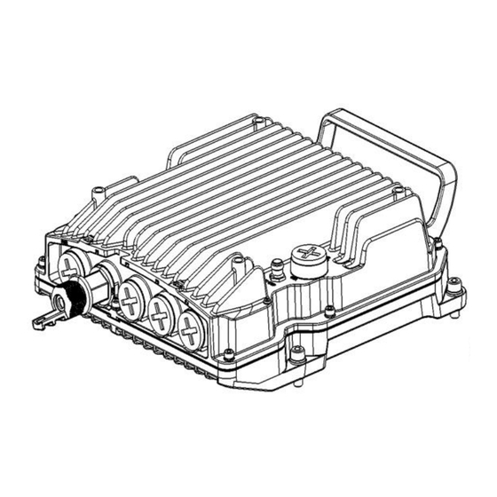
Page 16: Figure 3: Rfu-D-Hp Data And Power Interfaces
Installation Guide for RFU-D-HP Figure 3: RFU-D-HP Data and Power Interfaces • PWR: DC power interface (-48VDC) • P1: RFU Interface (RJ-45) • P2: RFU Interface (SFP) • P3: Data Sharing • P4: Reserved for future use. Note Note that in RFU-D-HP, Port 1 is the upper port, located closest to the handle, and Port 2 is the lower port, located closest to the Ethernet ports. -
Page 17: Figure 5: Cable Gland Construction
Installation Guide for RFU-D-HP Figure 5: Cable Gland Construction Note The voltage at the RSL port is 1.XX where XX is the RSL level. For example: 1.59V means an RSL of -59 dBm. Note that the voltage measured at the RSL port is not accurate and should be used only as an aid). -
Page 18: System Components - Diplexer-Based Branching
Installation Guide for RFU-D-HP System Components – Diplexer-Based Branching Note! Refer to the product roadmap for availability of RFU-D-HP in a specific band, as well as the availability of any specific mediation device. Presenting a specific component in this manual does not indicate that it is available for ordering. Please consult with your pre-sales engineer for specific component availability information. -
Page 19: Diplexer-Based Branching - Branching Components
Installation Guide for RFU-D-HP Diplexer-Based Branching – Branching Components Figure 8: OMT Figure 9:Space Diversity Branching Device Page 19 of 179... -
Page 20: Figure 10: Splitter
Installation Guide for RFU-D-HP Figure 10: Splitter Figure 11: Dual Coupler/Splitter/Circulator Page 20 of 179... -
Page 21: Diplexer-Based Branching - Accessory Components
Installation Guide for RFU-D-HP Diplexer-Based Branching – Accessory Components Figure 12: Remote Pole Mount Figure 13: Remote Pole Mount Adaptor Page 21 of 179... -
Page 22: System Components - Channel Filter-Based Branching
Installation Guide for RFU-D-HP System Components – Channel Filter-Based Branching Note! Refer to the product roadmap for availability of RFU-D-HP in a specific band, as well as the availability of any specific mediation device. Presenting a specific component in this manual does not indicate that it is available for ordering. Please consult with your pre-sales engineer for specific component availability information. -
Page 23: Figure 16: Short U-Bend
Installation Guide for RFU-D-HP Figure 16: Short U-Bend Figure 17: Long U-Bend Figure 18: Splitter/Coupler Figure 19: Termination Page 23 of 179... -
Page 24: Rfu-D-Hp Models And Marketing Models
Installation Guide for RFU-D-HP RFU-D-HP Models and Marketing Models Note! Refer to the product roadmap for availability of RFU-D-HP in a specific band, as well as the availability of any specific mediation device. Presenting a specific component in this manual does not indicate that it is available for ordering. Please consult with your pre-sales engineer for specific component availability information. - Page 25 Installation Guide for RFU-D-HP N060082L246A PTP 820C-HP/RFU-D-HP, Diplexer,U6 GHz, TR 340D, CH7W11, Lo,6625-6775MHz N060082L281A PTP 820C-HP/RFU-D-HP, Diplexer,U6 GHz, TR 150A, CH2W4, Hi,7050-7125MHz N060082L282A PTP 820C-HP/RFU-D-HP, Diplexer,U6 GHz, TR 150A, CH2W4, Lo,6900-6975MHz N110082L127A PTP 820C-HP/RFU-D-HP, Diplexer,11 GHz, TR 500, CH1W6, Hi,11185-11485MHz N110082L128A PTP 820C-HP/RFU-D-HP, Diplexer,11 GHz, TR 500, CH1W6, Lo,10695-10955MHz N110082L129A PTP 820C-HP/RFU-D-HP, Diplexer,11 GHz, TR 500, CH2W7, Hi,11225-11485MHz N110082L130A PTP 820C-HP/RFU-D-HP, Diplexer,11 GHz, TR 500, CH2W7, Lo,10735-10995MHz...
- Page 26 Installation Guide for RFU-D-HP N070082L339A PTP 820C-HP/RFU-D-HP Splitter,7-8 GHz N060082L226A PTP 820C-HP/RFU-D-HP OMT,6 GHz N070082L340A PTP 820C-HP/RFU-D-HP OMT,7-8 GHz N110082L141A PTP 820C-HP/RFU-D-HP OMT,11 GHz N060082L244A PTP 820C-HP/RFU-D-HP OMT Plate Adaptor, 6 GHz N110082L148A PTP 820C-HP/RFU-D-HP OMT Plate Adaptor, 11 GHz N070082L341A PTP 820C-HP/RFU-D-HP OMT Plate Adaptor, 7-8 GHz N060082L227A...
-
Page 27: Antenna Connection
10.0-11.7 WR90 UBR100 If a different antenna type (CPR flange) is used, a flange adaptor is required. Please contact your Cambium Networks representative for details. Note! Appropriate lubricant or grease can be applied to the screws that connect the RFU-D-HP to the antenna interface. -
Page 28: Power Specifications
Installation Guide for RFU-D-HP Power Specifications Electrical Requirements • Maximum Power Consumption: 130W Important Notes! • The unit must only be installed by service personnel. • The unit must have a permanent connection to protective grounding. • When using an external power source, the disconnect device (circuit breaker): Shall be readily accessible and incorporated external to the equipment. -
Page 29: Environmental Specifications
Installation Guide for RFU-D-HP Environmental Specifications Operating: ETSI EN 300 019-1-4 Class 4.1 Temperature range for continuous operating temperature with high reliability: -33°C (-27°F) to +55°C (131°F) Temperature range for exceptional temperatures; tested successfully, with limited margins: -45°C (-49°F) to +60°C (140°F) Humidity: 5%RH to 100%RH IEC529 IP66 Storage: ETSI EN 300 019-1-1 Class 1.2... -
Page 30: Chapter 3 Grounding The Rfu-D-Hp
Installation Guide for RFU-D-HP Chapter 3 Grounding the RFU-D-HP List of Items Table 4: Grounding Cable Description Quantity N000082L116A PTP 820 GROUND CABLE FOR IDU and ODU Required Tools • Metric offset wrench key wrench #3 • Metric wrench 10mm Procedure On the front of each RFU-D-HP unit, loosen the nut, plain washer, and serrated washer from the GND stud, using the metric offset hexagon key and the wrench. -
Page 31: Chapter 4 Connecting The Data And Power Cables
Installation Guide for RFU-D-HP Chapter 4 Connecting the Data and Power Cables RFU-D-HP is connected to the IDU via a standard CAT-5e or preferably CAT-6/6a cable, with RJ-45 connectors on the RFU and an RJ-45 connector on the IDU. They can also be connected to the IDU over optical fiber cables via the optical (SFP) RFU connections on the IDU. -
Page 32: Grounding The Cables
Installation Guide for RFU-D-HP Grounding the Cables To fit the gland, the outer cable diameter should be between 6-10 mm. Cables must be grounded as follows. • For fiber cables (see Connecting an Optical Fiber Cable and SFP on page 48), no grounding is required. •... - Page 33 Installation Guide for RFU-D-HP To connect the grounding kit: Strip the cable jacket about 1.5 cm (.5”). 1.5cm .5" Braided Smoothwall Cable Cable Loop the grounding wire’s braid belt (1) around the stripped portion of the cable, insert the rest of the grounding wire (5) through the braid belt, and tighten to form a knot, as shown in the figure below.
- Page 34 Installation Guide for RFU-D-HP Grasp the terminal of the braid belt (2) and slide it flush with the knot around the cable, as shown in the figure below. Crimp the knotted braid belt (1) and the bare terminal (10) together, as shown in the figures below. Page 34 of 179...
- Page 35 Installation Guide for RFU-D-HP Wrap the butyl rubber sealing clay (13) around the cable and the grounding wire, as shown in the figures below. Cut four strips of the tape (12), approximately 20 cm (8”) each, and wrap these strips of tape around the butyl rubber sealing clay (13), as shown in the figures below.
- Page 36 Installation Guide for RFU-D-HP Pass the hex bolt (6) through the copper lug at the end of the grounding wire (4), and secure it to the grounding bar using the flat washer (7), the spring washer (8), and the nut (9). Use conductive grease (11) on the bolt and nut to ensure proper contact.
-
Page 37: Power Source
Installation Guide for RFU-D-HP Power Source When selecting a power source, the following must be considered: DC power can be from -40.5 to -59 VDC. Recommended: Availability of a UPS (Uninterrupted Power Source), battery backup, and emergency power generator. The power supply must have grounding points on the AC and DC sides. Caution! The user power supply GND must be connected to the positive pole in the RFU-D-HP power supply. -
Page 38: Surge Protection
Installation Guide for RFU-D-HP Surge Protection RFU-D-HP includes built-in surge protection for its power and RJ-45 data ports (PWR, P1, P4). RFU-D-HP’s surge protection implementation for this port complies with EN61000-4-5, Class 4 , provided the cable was prepared according to the instructions in Connecting a CAT-5e/CAT-6 Data Cable on page 55. In areas in which severe lighting conditions are likely to occur, it is strongly recommended to add additional protection by placing lightning protectors on the CAT-5e or CAT-6 cable, near the connection point with the RFU-D-HP unit. -
Page 39: Available Cable Options
Installation Guide for RFU-D-HP Available Cable Options Fiber Optic Cables - Single Mode Table 7: Fiber Optic Cables - Single Mode Description N000082L176A PTP 820 Optical CABLE,SM, 5m N000082L139A PTP 820 Optical CABLE,SM, 30m N000082L140A PTP 820 Optical CABLE,SM, 50m N000082L141A PTP 820 Optical CABLE,SM, 80m N000082L142A... -
Page 40: Figure 21: Cable Design
Installation Guide for RFU-D-HP This cable has the following specifications: • Suitable for: Fast Ethernet Gigabit Ethernet Cable Design – The numbers in the figure below refer to the items listed beneath the figure. Figure 21: Cable Design • [1] Conductor •... -
Page 41: Outdoor Cat-5E Cable Specifications
Installation Guide for RFU-D-HP Outdoor CAT-5e Cable Specifications Table 12: Outdoor CAT-5e Cable Specifications – Electrical Requirements Cable type CAT-5e SFUTP, 4 pairs, according to ANSI/TIA/EIA-568-B-2 Wire gage 24 AWG Stranding Solid Voltage rating Shielding Tinned copper Braid (Coverage: >=80%) + Aluminum Foil Pinout Table 13: Outdoor CAT-5e Cable Specifications –... -
Page 42: Securing The Cables
Installation Guide for RFU-D-HP Securing the Cables All cables should be secured at every meter on-site using either a T-Rups kit, Marketing Model “Outdoor Ties”, or cable clamps. When using the T-Rups kit, take special care to apply the proper amount of force in order to avoid damage to the cable. -
Page 43: Special Instructions For Use Of Glands
Installation Guide for RFU-D-HP Special Instructions for use of Glands Note Each RFU-D-HP unit is supplied with one gland. If additional glands are required, they must be ordered separately, in kits of five glands each. Table 15: Glands Kit Description N000082L014A PTP 820 Glands_x5_KIT In addition, gland caps can be ordered to protect the cable and connector from damage when elevating the cable and... - Page 44 Installation Guide for RFU-D-HP Slide the gland cap into the cable. Slide the gland rubber into the cable. Slide the cable into the body of the gland. If you are using a gland cap (see Step 5), make sure to leave enough space for the gland cap to fit into the gland without disturbing the cable.
- Page 45 Installation Guide for RFU-D-HP Optionally, after securing the cable into the body of the gland, you can close the other side of the gland with an M28 gland cap. The gland cap protects the cable and connector from damage when elevating the cable and gland to the radio unit.
- Page 46 Installation Guide for RFU-D-HP Important Note! Before tightening the gland, make sure the gland is aligned with the tapped hole in the unit. Tightening the gland at an angle can ruin the thread on the gland and prevent proper sealing of the interface. 10 Insert the main part of the gland into the thread in the radio body and tighten until there is full contact and the gasket is fully contained between the gland and the radio and cannot be seen.
-
Page 47: Figure 23: Tightening The Rear Portion Of The Gland
Installation Guide for RFU-D-HP Figure 22: Tightening the Front Portion of the Figure 23: Tightening the Rear Portion of the Gland Gland 12 Secure the cable to the lip of the gland using a tie wrap. Page 47 of 179... -
Page 48: Connecting An Optical Fiber Cable And Sfp
Installation Guide for RFU-D-HP Connecting an Optical Fiber Cable and SFP When using an optical fiber cable, the cable must be inserted in port P2. A separate DC power cable must be used to connect the RFU-D-HP to an external power source. See Connecting a DC Power Cable. To connect an optical fiber cable and the SFP transceiver: Use a pre-assembled cable. - Page 49 Installation Guide for RFU-D-HP Insert the fibers with the connectors one by one into the cable gland. Secure the cable to the lip of the gland using a tie wrap. Important Note! If you are raising the cable to a radio unit on a tower, this step is crucial to prevent the cable from slipping from the gland, which could damage the connector.
- Page 50 Installation Guide for RFU-D-HP Connect the fibers to the SFP transceiver. Listen for the “click” to ensure that they are fully inserted. Remove the tie wrap securing the cable to the gland. Note: A new tie wrap must be used to secure the cable to the gland at the end of the procedure, as described in Step 13.
- Page 51 Installation Guide for RFU-D-HP 10 Connect the connector into the RFU-D-HP connector. 11 Tighten the gland to the radio unit until there is full contact between the gland and the radio unit. 12 Tighten the gland cap. Important Note! Before tightening the gland, make sure the gland is aligned with the tapped hole in the unit.
- Page 52 Installation Guide for RFU-D-HP 13 Secure the cable to the gland using a tie wrap. Page 52 of 179...
-
Page 53: Connecting A Dc Power Cable
Installation Guide for RFU-D-HP Connecting a DC Power Cable A DC power cable must be connected to port P1 to provide power from an external power source to the RFU. To connect a DC power cable: Strip off 45 mm from the cable jacket. Expose 10 mm at the edge of each of the two wires. - Page 54 Installation Guide for RFU-D-HP Plug the power cable with connector into the PWR port. Screw the gland into the radio unit Important Note! Before tightening the gland, make sure the gland is even with the cover. Tighten the gland gently and make sure there is no resistance. If there is resistance, stop immediately and verify that the gland is not being inserted at an angle.
-
Page 55: Connecting A Cat-5E/Cat-6 Data Cable
Installation Guide for RFU-D-HP Connecting a CAT-5e/CAT-6 Data Cable If you need to assemble the CAT-5e or CAT-6 cable, follow the instructions in section 0, Preparing the CAT-5e or CAT-6 Cable and Plug-in Field, then proceed to section 0, Connection of CAT-5e or CAT-6 Cable to RFU-D-HP. If you using a pre-assembled CAT-5e or CAT-6 cable, follow the instructions in section 0, Preparing the CAT-5e or CAT-6 Data Cable Already Assembled, then proceed to section 0, Connection of CAT-5e or CAT-6 Cable to RFU-D-HP. - Page 56 Installation Guide for RFU-D-HP Roll back the foil shield insulation and wrap the drain wire around the foil. Do not remove any insulation from the conductors. Align the colored wires. Note: Cord colors should be matched to the same pins on both ends of the cable. Trim all wires to the same length.
-
Page 57: Preparing The Cat-5E Or Cat-6 Data Cable Already Assembled
Installation Guide for RFU-D-HP 11 Crimp the RJ45 plug with the crimp tool. Make sure the twisted shield is crimped firmly to the RJ45 plug. 12 Verify that the wires ended up the correct order and that the wires extend to the front of the RJ45 plug and make good contact with the metal contacts in the RJ45 plug. -
Page 58: Connection Of Cat-5E Or Cat-6 Cable To Rfu-D-Hp
Installation Guide for RFU-D-HP Insert the CAT-5e or CAT-6 cable into the gland body. Connection of CAT-5e or CAT-6 Cable to RFU-D-HP To connect the CAT-5e or CAT-6 cable to the RFU-D-HP: Remove the relevant cap from the RFU-D-HP radio. You can use the side of the gland to unscrew the cap. -
Page 59: Chapter 5 General Notes Concerning All Installation Procedures
Installation Guide for RFU-D-HP Chapter 5 General Notes Concerning All Installation Procedures Some of the configurations described in this manual may not be supported with every Release version. For up-to-date information about which configurations are supported, refer to the Release Notes for the Release version you are using. Note that 4 and 5 GHz links are currently supported only with diplexer-based branching and remote-mount configurations. -
Page 60: Chapter 6 Installation Instructions For Configurations With Diplexer-Based Branching
Installation Guide for RFU-D-HP Chapter 6 Installation Instructions for Configurations with Diplexer-Based Branching Page 60 of 179... -
Page 61: Torque Requirements
Installation Guide for RFU-D-HP Torque Requirements When tightening the captive screws, use 20 Nm torque for radio-antenna, radio-mediation device, and mediation device-antenna connections. In order to avoid misalignment, screws should be tightened progressively. For installing the diplexer unit on the radio, use 5 Nm torque. When fastening a waveguide to the radio or mediation device, use the following torque, according to frequency and screw type: •... -
Page 62: General Radio Installation
Installation Guide for RFU-D-HP General Radio Installation The RFU-D-HP has been designed for easy installation, with various installation options to provide maximum flexibility. In most cases, the Diplexers unit should be attached to the antenna or mediation device first. Then, attach the radio unit to the Diplexers unit. -
Page 63: Installing The Diplexer On The Radio
Installation Guide for RFU-D-HP Installing the Diplexer on the Radio For configurations that use diplexers, RFU-D-HP is delivered as two separate components: a generic radio unit and a diplexer unit. This section explains how to attach the diplexer unit to the radio unit. Note: Mounting of the diplexer unit to the radio unit should be performed by certified personnel in a clean, temperature and humidity-controlled environment. -
Page 64: Figure 26: Fitting The Diplexer Unit To The Radio Unit - Radio Side
Installation Guide for RFU-D-HP Attach the diplexer to the TRX using the two location pins. Make sure that the hook and the carrying handle are on the same side in both the radio unit and the diplexer unit (Figure 29). Figure 26: Fitting the Diplexer Unit to the Radio Unit - Radio Side Figure 27: Fitting the Diplexer Unit to the Radio Unit - Diplexer Unit Side Page 64 of 179... -
Page 65: Figure 28: Radio And Diplexer Units Together
Installation Guide for RFU-D-HP Figure 28: Radio and Diplexer Units Together Figure 29: Hook and Carrying Handle Secure the diplexer unit to the radio unit using the eight M5 screws supplied with the radio unit. First, gently tighten the screws in the order shown in Figure 30. Then strongly tighten the screws in the same order. -
Page 66: Figure 30: Securing The Diplexer Unit To The Radio Unit
Installation Guide for RFU-D-HP Figure 30: Securing the Diplexer Unit to the Radio Unit Proceed to install the RFU-D-HP in the desired configuration, as described in the following sections. Page 66 of 179... -
Page 67: 2+0 Dual Polarization Direct Mount
Installation Guide for RFU-D-HP 2+0 Dual Polarization Direct Mount Note: This procedure can also be used for 1+0 DP HW ready for 2+0 DP configuration. List of Items Descripti Quanti Marketing Model RFU-D- See Section 0, HP Radio Note! Unit Refer to the product roadmap for availability of RFU-D-HP in a specific band, as well as the availability of any specific mediation device. - Page 68 Installation Guide for RFU-D-HP Procedure Prior to the installation, follow the antenna manufacturer’s instructions to use the circular adaptor. (Remove the existing rectangular transition, swap the O-ring, and install the circular transition instead.) Connect the OMT kit to the antenna and secure it with four screws. Important Note! Verify that the O-ring is properly mounted between the antenna transition and the OMT.
- Page 69 Installation Guide for RFU-D-HP Page 69 of 179...
-
Page 70: 2+0 Dual Polarization Remote Mount
Installation Guide for RFU-D-HP 2+0 Dual Polarization Remote Mount This procedure is for use with Interface antennas, up to six feet. For standard interface antennas (six feet and larger), no OMT and no Circ./Circ. Adaptor are used, and the flexible waveguides are connected directly to the antenna flanges. - Page 71 Installation Guide for RFU-D-HP Adaptor DXDH-RM-MOUNT-ADPT-ff Remote Mount Circ./Cir Per Antenna Vendor. Not used for standard interface antennas (six feet and larger). Adaptor Required Tools • Metric offset hexagon key set • Metric wrench key set Common Installation Prior to the installation, follow the antenna manufacturer’s instructions for using the circular transition (adaptor). Remove the existing rectangular transition, swap the O-ring, and install the circular transition instead.
- Page 72 Installation Guide for RFU-D-HP Mount and tighten the Remote Mount Adaptor to the RFU-D-HP OMT ports using the screws supplied with the adapter kit. Mount and tighten the O-ring and the flexible waveguide to the adapter ports using the screws supplied with the flexible waveguide kit.
-
Page 73: Figure 31: Remote Pole Mount Kit - 6-11 Ghz
Installation Guide for RFU-D-HP Important Note! Verify that the O-rings are correctly mounted between the OMT ports and each flexible waveguide. Mount and tighten the RFU-D-HP DC pole mount to the pole using the four washers and screws supplied with the RFU- D-HP DC pole mount kit: For 4-5 GHz configurations, use 39 Nm torque For 6-11 GHz configurations, use 39 Nm torque... -
Page 74: Figure 33: Remote Pole Mount Kit - 6-11 Ghz
Installation Guide for RFU-D-HP Figure 33: Remote Pole Mount Kit – 6-11 GHz Figure 34: Remote Pole Mount Kit – 4-5 GHz Mount and tighten the RFU-D-HP Radio to the RFU-D-HP Pole Mount using the four flat screws supplied with the RFU- D-HP Radio. - Page 75 Installation Guide for RFU-D-HP Page 75 of 179...
-
Page 76: 2+0 Single Polarization Direct Mount
Installation Guide for RFU-D-HP 2+0 Single Polarization Direct Mount Note: This procedure can also be used for 1+0 SP HW ready for 2+0 SP configuration. List of Items Descripti Quanti Marketing Model RFU-D- See Section 0, Note! RADIO Refer to the product roadmap for availability of RFU-D-HP in a specific band, as well as the availability of any specific mediation device. - Page 77 Installation Guide for RFU-D-HP ▪ For vertical polarization, locate the twist with the letter “V” on top. Mount and tighten the RFU-D-HP Splitter Kit on the antenna using the four M8 screws and washers. Note: Verify that the O-ring is properly mounted between the antenna transition and the splitter. Page 77 of 179...
- Page 78 Installation Guide for RFU-D-HP Connect the RFU-D-HP DC radio to the splitter kit using the four M8 captive screws and washers supplied, and tighten the screws. Note: Verify that the O-rings are properly mounted between the OMT ports and the radio/dual coupler. Page 78 of 179...
-
Page 79: 2+2 Hsb Double Polarization Direct Mount
Installation Guide for RFU-D-HP 2+2 HSB Double Polarization Direct Mount Note: This procedure can also be used for 2 x 1+1 HSB DP HW ready for 2+2 HSB DP configurations. List of Items Descripti Quanti Marketing Model RFU-D- See Section 0, HP Radio Note! Refer to the product roadmap for availability of RFU-D-HP in a specific band, as well as the... - Page 80 Installation Guide for RFU-D-HP Required Tools • Metric offset hexagon key set • Metric wrench key set Procedure Prior to the installation, follow the antenna manufacturer’s instructions to use the circular adaptor. (Remove the existing rectangular transition, swap the O-ring, and install the circular transition instead.) Connect the RFU-D-HP OMT Kit to the antenna and secure it with four screws.
- Page 81 Installation Guide for RFU-D-HP Mount and tighten the RFU-D-HP DC radio unit to both sides of the Dual Coupler Kit using the supplied captive screws and washers. Pay attention that the O-rings are correctly mounted on the radio ports of the RFU-D-HP Dual Coupler.
-
Page 82: 2+2 Hsb Double Polarization Remote Mount
Installation Guide for RFU-D-HP 2+2 HSB Double Polarization Remote Mount Note: This procedure can also be used for 2x 1+1 HSB DP HW ready for 2+2 HSB DP configurations. List of Items Descripti Quanti Marketing Model RFU-D- See Section 0, Note! RADIO Refer to the product roadmap for availability of RFU-D-HP in a specific band, as well as the... - Page 83 Installation Guide for RFU-D-HP RFU-D- DXDH-RM-MOUNT-ADPT-ff HP DC POLE MOUNT RFU-D- DXDH-RM-MOUNT-ADPT-ff HP DC Not Required for 4-5 GHz Adaptor Remote Mount Kit, ff CIRC./CI Per Antenna Vendor. ADAPTO Required Tools • Metric offset hexagon key set • Metric wrench key set •...
- Page 84 Installation Guide for RFU-D-HP Connect the OMT Kit to the antenna and secure it with four screws. Verify the existence of the O-ring. Mount and tighten the Remote Mount Adapter to the RFU-D-HP OMT ports using the screws supplied with the adapter kit.
- Page 85 Installation Guide for RFU-D-HP Mount and tighten the O-ring and the flexible waveguide to the adapter ports using the screws supplied with the flexible waveguide kit. Note: Verify that the O-rings are correctly mounted between the OMT ports and each flexible waveguide. Page 85 of 179...
- Page 86 Installation Guide for RFU-D-HP Mount and tighten the RFU-D-HP DC pole mount to the pole using the four washers and screws supplied with the RFU-D-HP DC pole mount kit. See Steps 0 and 0 in Section Chapter 0, 2+0 Dual Polarization Remote Mount. Mount and tighten the RFU-D-HP Remote Mount Adaptor plate (supplied in RFU-D-HP Adaptor Remote Mount kit) to the RFU-D-HP Pole Mount using the four flat screws supplied with the RFU-D-HP Adaptor Remote Mount kit.
- Page 87 Installation Guide for RFU-D-HP Mount and tighten the RFU-D-HP Dual Coupler to the RFU-D-HP Pole Mount using the four screws and washers that are supplied with the RFU-D-HP Dual Coupler kit. Pay attention that the O-rings are mounted on the RFU-D-HP Remote Mount Adaptor.
- Page 88 Installation Guide for RFU-D-HP 10 Connect both Flexible Waveguides and Sealing Gaskets supplied with each Flexible Waveguide Kit to the RFU-D-HP Dual Coupler antenna ports. Tighten the screws and washers supplied with the Flexible Waveguide Kit. Page 88 of 179...
-
Page 89: 2+2 Hsb Single Polarization Direct Mount
Installation Guide for RFU-D-HP 2+2 HSB Single Polarization Direct Mount Note: This procedure can also be used for 2 x 1+1 HSB SP HW ready for 2+2 HSB SP configurations. List of Items Descriptio Quanti Marketing Model RFU-D-HP See Section 0, RADIO Note! Refer to the product roadmap for availability of RFU-D-HP in a specific band, as well as the... - Page 90 Installation Guide for RFU-D-HP Procedure Adjust the twist on the Splitter Kit. Perform one of the procedures below, according to the required polarization (horizontal or vertical). ▪ For horizontal polarization, locate the twist with the letter “H” on top. ▪ For vertical polarization, locate the twist with the letter “V”...
- Page 91 Installation Guide for RFU-D-HP Page 91 of 179...
- Page 92 Installation Guide for RFU-D-HP Mount the Splitter Kit on the antenna using four M8 screws and washers and tighten the screws. Connect the RFU-D-HP Dual Coupler Kit to the Splitter Kit using four M8 screws and washers, and tighten the screws. Page 92 of 179...
- Page 93 Installation Guide for RFU-D-HP Page 93 of 179...
- Page 94 Installation Guide for RFU-D-HP Mount and tighten the RFU-D-HP DC radio unit to both sides of the Dual Coupler Kit using the supplied captive screws and washers. Pay attention that the O-rings are correctly mounted on the radio ports of the RFU-D-HP Dual Coupler.
-
Page 95: 2+2 Hsb Single Polarization Remote Mount
Installation Guide for RFU-D-HP 2+2 HSB Single Polarization Remote Mount Note: This procedure can also be used for 1+1HSB SP HW ready for 2+2HSB SP configurations. ACCP - Protected List of Items Descripti Quanti Marketing Model RFU-D- See Section 0, Note! RADIO Refer to the product roadmap for availability of RFU-D-HP in a specific band, as well as the... - Page 96 Installation Guide for RFU-D-HP RFU-C RFU-C-POLEMOUNT POLE MOUNT Required Tools • Metric offset hexagon key set • Metric wrench key set • Phillips #1, #2 screwdriver Procedure Mount and tighten the RFU-D-HP Remote Mount Adaptor plate (supplied in the RFU-D-HP Adaptor Remote Mount kit) to the RFU-D-HP Pole Mount using the four flat screws supplied with the RFU-D-HP Adaptor Remote Mount kit.
- Page 97 Installation Guide for RFU-D-HP Mount and tighten the RFU-D-HP Dual Coupler to the RFU-D-HP Splitter using the four captive screws and washers that are supplied with the RFU-D-HP Dual Coupler kit. Make sure that the O-rings are mounted on the RFU-D-HP Splitter. Attach the Diplexer unit to the Dual Coupler using 8 M4 screws provided with the Diplexer kit, as shown below, using 20Nm torque.
- Page 98 Installation Guide for RFU-D-HP the top Diplexer and then the lower right screw of the bottom Diplexer. Once the outer screws have all been partially tightened, repeat this process in a similar fashion with the central screws. Then proceed to fully tighten all the screws in the same order. Important: Verify that the O-rings on the Dual Coupler are properly mounted between the Dual Coupler ports and the Diplexer unit.
- Page 99 Installation Guide for RFU-D-HP Attach the Radio unit to the Diplexer unit using the 8 M5 captive screws supplied with the Radio kit. Position the Radio unit on the Diplexer unit so that the two location pins mounted on the TRX ports of the Diplexer unit fit into the corresponding holes in the Radio unit.
-
Page 100: 2+0 Bbc Space Diversity Direct Mount
Installation Guide for RFU-D-HP 2+0 BBC Space Diversity Direct Mount List of Items Descripti Quanti Marketing Models RFU-D- See Section 0, HP Radio Note! Refer to the product roadmap for availability of RFU-D-HP in a specific band, as well as the availability of any specific mediation device. - Page 101 Installation Guide for RFU-D-HP Procedure For instructions on installation of the RFU-D-HP OMT and radios, see 2+0 Dual Polarization Direct Mount on page 67. Connect the source sharing cable between both EXT REF RFU-D-HP radio connectors. The maximum torque for connecting this cable to the radio is 5Lb.in (0.5N.m). Connect the data sharing cable between both P3 RFU-D-HP ports.
- Page 102 Installation Guide for RFU-D-HP Page 102 of 179...
-
Page 103: 4+0 Bbc Space Diversity Direct Mount
Installation Guide for RFU-D-HP 4+0 BBC Space Diversity Direct Mount List of Items Descripti Quanti Marketing Model RFU-D- See Section 0, HP Radio Note! Refer to the product roadmap for availability of RFU-D-HP in a specific band, as well as the availability of any specific mediation device. - Page 104 Installation Guide for RFU-D-HP Important: Verify that the O-ring is properly mounted between the antenna transition and the OMT. O-Ring Connect the RFU-D-HP Dual Splitter or Dual Circulator kit to the OMT using four M8 screws and washers, supplied in the Dual Coupler, and tighten the screws. Important: Verify that the O-rings on the OMT are properly mounted between the OMT ports and the Dual Splitter/Dual Circulator.
- Page 105 Installation Guide for RFU-D-HP Make sure the following items are attached to the Dual Splitter or Dual Circulator before attaching the Diplexer units: • Four plastic washers on either side of the Dual Splitter or Dual Circulator on the surface around the screw threads for the Diplexer unit.
- Page 106 Installation Guide for RFU-D-HP Note: The screws should be tightened diagonally. Fasten the upper right screw of the top Diplexer and then the lower left screw of the bottom Diplexer, then fasten the upper left screw of the top Diplexer and then the lower right screw of the bottom Diplexer. Once the outer screws have all been partially tightened, repeat this process in a similar fashion with the central screws.
- Page 107 Installation Guide for RFU-D-HP Location Pin Hole (Not Shown) Location Location Location Pin (Not Shown) Pin Hole 8 M5 Captive Screws Repeat steps 4-6 to attach the second Diplexer unit and the second Radio unit to the other side of the Dual Splitter or Dual Circulator.
- Page 108 Installation Guide for RFU-D-HP b) Connect the data sharing cable between both P3 RFU-D-HP ports. Page 108 of 179...
-
Page 109: 4+0 Single/Dual Polarization, Direct Mount
Installation Guide for RFU-D-HP 4+0 Single/Dual Polarization, Direct Mount List of Items Descriptio Quanti Marketing Model RFU-D-HP See Section 0, Radios Note! Refer to the product roadmap for availability of RFU-D-HP in a specific band, as well as the availability of any specific mediation device. Presenting a specific component in this manual does not indicate that it is available for order Please consult with your pre-sales engineer for specific component availability information. - Page 110 Installation Guide for RFU-D-HP Note: Verify that the O-ring is properly mounted between the antenna transition and the OMT/Splitter. If you are using a Splitter, adjust the twist on the Splitter Kit. Perform one of the following steps, according to the required polarization (horizontal or vertical). ▪...
- Page 111 Installation Guide for RFU-D-HP Connect the RFU-D-HP Dual Coupler or Dual Splitter kit to the OMT/Splitter using four M8 screws and washers, supplied in the Dual Coupler, and tighten the screws. Note: Verify that the O-rings on the OMT or Splitter are properly mounted between the OMT/Splitter ports and the Dual Coupler/Dual Splitter.
- Page 112 Installation Guide for RFU-D-HP Make sure the following items are attached to the Dual Coupler or Splitter before attaching the Diplexer units: • Four plastic washers on either side of the Dual Coupler or Splitter on the surface around the screw threads for the Diplexer unit.
- Page 113 Installation Guide for RFU-D-HP Note: The screws should be tightened diagonally. Fasten the upper right screw of the top Diplexer and then the lower left screw of the bottom Diplexer, then fasten the upper left screw of the top Diplexer and then the lower right screw of the bottom Diplexer. Once the outer screws have all been partially tightened (torque ??), repeat this process in a similar fashion with the central screws.
- Page 114 Installation Guide for RFU-D-HP Location Pin Hole (Not Shown) Location Location Location Pin Pin Hole (Not Shown) 8 M5 Captive Screws Repeat steps 5-7 to attach the second Diplexer unit and the second Radio unit to the other side of the Dual Coupler, Dual Splitter, or Dual Circulator.
-
Page 115: 4+0 Dual Polarization, Remote Mount
Installation Guide for RFU-D-HP 4+0 Dual Polarization, Remote Mount List of Items Description Quant Marketing Model RFU-D-HP See Section 0, Radios Note! Refer to the product roadmap for availability of RFU-D-HP in a specific band, as well as the availability of any specific mediation device. Presenting a specific component in this manual does not indicate that it is available for ord Please consult with your pre-sales engineer for specific component availability information Radio Unit... - Page 116 Installation Guide for RFU-D-HP Mount and tighten the RFU-D-HP Remote Mount Adaptor plate (supplied in the RFU-D-HP Adaptor Remote Mount kit) to the RFU-D-HP Pole Mount using the four flat screws supplied with the RFU-D-HP Adaptor Remote Mount kit. See Steps 0 and 0 in Section Chapter 0, 2+0 Dual Polarization Remote Mount.
- Page 117 Installation Guide for RFU-D-HP Note: Tighten the screws diagonally. First begin to fasten the upper right screw of the top Diplexer and then the lower left screw of the bottom Diplexer, then fasten the upper left screw of the top Diplexer and then the lower right screw of the bottom Diplexer. Once the outer screws have all been partially tightened, repeat this process in a similar fashion with the central screws.
- Page 118 Installation Guide for RFU-D-HP Secure the edges of the Diplexer unit to the Dual Circulator/Splitter using the four M8 captive screws and washers supplied with the Diplexer kit, using 20Nm torque. These screws are colored blue in the following picture. Be sure to tighten the screws in the same diagonal manner as in the previous step. 4 M8 Screws Attach the Radio unit to the Diplexer unit using the 8 M5 captive screws supplied with the Radio kit.
- Page 119 Installation Guide for RFU-D-HP Attach the OMT Remote Mount Adapter to the OMT using the screws supplied with the OMT Remote Mount Adapter kit. 10 Connect both Flexible Waveguides and Sealing Gaskets supplied with each Flexible Waveguide Kit to the OMT Remote Mount Adaptor using the screws supplied with the Flexible Waveguide kits.
- Page 120 Installation Guide for RFU-D-HP Page 120 of 179...
-
Page 121: 4+0 With Dual Circulator Remote Mount
Installation Guide for RFU-D-HP 4+0 with Dual Circulator Remote Mount The following example illustrates a typical configuration, assuming that: • The regulation specifies a channelization of 8 consecutive 28/38MHz channels (1-8 ch). • The actual channels in use are channels 1,5. Page 121 of 179... -
Page 122: Dual Circulator Multi-Carrier Kit Installation
Installation Guide for RFU-D-HP Dual Circulator Multi-Carrier Kit Installation List of Items Descripti Quanti Marketing Model RFU-D- See Section 0, Note! RADIO Refer to the product roadmap for availability of RFU-D-HP in a specific band, as well as the availability of any specific mediation device. Presenting a specific component in this manual does not indicate that it is available for orderin Please consult with your pre-sales engineer for specific component availability information. - Page 123 Installation Guide for RFU-D-HP 6-8 GHz Mount and tighten the RFU-D-HP MC Dual Cir to the RFU-D-HP pillar adapter bracket using the four M8 Hex screws and washers supplied within the kit. 11 GHz only Mount and tighten the RFU-D-HP MC extender to the RFU-D-HP pillar adapter bracket using the four M8 Hex screws and washers supplied within the kit.
- Page 124 Installation Guide for RFU-D-HP Mount and tighten the RFU-D-HP MC Dual Cir to the RFU-D-HP MC Extender using the four M8 Hex screws and washers supplied within the kit. 6-11GHz Mount and tighten the RFU-D-HP Dual Cir to each side of the IP-20 MC Dual Circ using the four M8 Hex screws and washers supplied in the IP-20 Dual Circ kit.
- Page 125 Installation Guide for RFU-D-HP Mount and tighten the RFU-D-HP radios to each RFU-D-HP Dual Circ radio port using the four screws assembled on the RFU-D-HP radio. Pay attention that the O-rings on the RFU-D-HP Dual Circ are well in place during the mounting. Mount and tighten the RFU-D-HP MC Remote mount adapter to the RFU-D-HP MC Dual Circ antenna ports using the four screws assembled on the RFU-D-HP radio.
- Page 126 Installation Guide for RFU-D-HP Mount and tighten the O-ring and the Flexible WG to the RFU-D-HP MC Remote mount adapter ports using the four screws supplied with the Flexible WG kit. Mount and tighten the O-ring and flexible WG to both antenna ports using the four screws supplied with the flexible WG kit.
- Page 127 Installation Guide for RFU-D-HP High Channels Radio (i.e Ch5 V&H) Low Channels Radio (i.e Ch1 V&H) Low Channels Radio (i.e Ch1 V&H) High Channels Radio (i.e Ch5 V&H) Antenna Ports 1 2 3 4 5 6 7 8 1 2 3 4 5 6 7 8 Page 127 of 179...
-
Page 128: Chapter 7 Installation Instructions For Configurations With Channel Filter-Based Branching121
Installation Guide for RFU-D-HP Chapter 7 Installation Instructions for Configurations with Channel Filter-Based Branching Channel filter-based branching configurations utilize the following components: • • OCU Mounting Kit • Short U-Bend • Long-U-Bend • Termination • Splitter/Coupler This chapter is set up as follows: •... -
Page 129: Channel Filter-Based Branching - Component Assembly
Installation Guide for RFU-D-HP Channel Filter-Based Branching – Component Assembly Assembling the OCU Mounting Kit This section explains how to attach the OCU mounting kit for RFU-D-HP radio units to a 114 mm pole. List of Items Item Description Quantity Marketing Model RFU-D-HP Branching Pole Profile Part of OCU Mounting kit, FXDH-RM-MOUNT-... - Page 130 Installation Guide for RFU-D-HP Procedure Mount and tighten the two Branching Pillars to a pole with a diameter of 114 mm using the four M10x150 screws, four washers, and eight nuts supplied with the OCU Mounting kit. Use torque of 45 Nm.
-
Page 131: Assembling The Ocu
Installation Guide for RFU-D-HP Assembling the OCU List of Items Item Description Quantity RFU-D-HP OCU Kit 1 per radio See Section Error! Reference source not found., Error! Reference source not found. OCU Body 1 per OCU kit Included in OCU kit OCU Rail 1 per OCU kit Included in OCU kit... - Page 132 Installation Guide for RFU-D-HP 7 - Washers, Helical 4– M8x25 Screw 5 - M8x30 Screw 6– Washers, Plain spring lock 8 – Branching Pole Profile Required Tools • Metric offset wrench key wrench set • Metric Allen key set Required Torque •...
-
Page 133: Figure 35: Left Rail Configuration
Installation Guide for RFU-D-HP • With the nose of the rail protruding to the right when facing the inside of the OCU (Figure 36). Figure 35: Left Rail Configuration Figure 36: Right Rail Configuration Figure 37 shows the Left Rail and Right Rail configurations in the context of a full configuration in which four radios and four OCUs are attached to the Branching Pole Profile. -
Page 134: Figure 38: Attaching The Radio To The Ocu
Installation Guide for RFU-D-HP Connecting the OCU to the RFU-D-HP Radio Attach the M5 captive screws on the radio to the OCU kit, as shown in Figure 38. Partially fasten the screws, without tightening them, in a diagonal fashion as shown in Figure 39. Once all the screws have been partially fastened, tighten all the screws in the same order, using 5.5 Nm torque. -
Page 135: Figure 41: Final Position Of Ocu-Radio Locked Into Branching Pole Profile
Installation Guide for RFU-D-HP Level the OCU-radio unit so that the nose of the OCU Rail is locked underneath and inside of the nose of the Branching Pole Profile (Figure 41). Figure 41: Final Position of OCU-Radio Locked into Branching Pole Profile Partially attach the OCU-radio unit to the Branching Pole Profile with the two M8-30 screws included in the OCU kit, along with the remaining helical and flat washers, as shown in Figure 42. -
Page 136: Assembling A Short U-Bend
Installation Guide for RFU-D-HP Waveguide Assemblies At this point in the installation, you must install all required waveguide assemblies, such as U-Bends, Flexible Waveguides, and Terminations. For instructions, refer to the specific type of configuration you are installing in Section Chapter 0, Channel Filter-Based Branching – Configurations. Tightening the M8-30 Screws When you have finished installing all waveguides, and all of the radio ports have been covered, you must fully tighten the two M8-30 screws that attach the OCU-radio unit to the Branching Pole Profile as shown above in Figure 42. - Page 137 Installation Guide for RFU-D-HP List of Items Item Description Quantity RFU-D-HP Branching Short U-Bend Depends on FXDH-RM-U-Bend-06 Configuration FXDH-RM-U-Bend-7-8 FXDH-RM-U-Bend-11 #8-32 Socket Hex Screws 12 Per U-Bend Embedded in U-Bend 1 – Short U-Bend Required Tools • Imperial Allen key set Required Torque •...
-
Page 138: Assembling A Long U-Bend
Installation Guide for RFU-D-HP Procedure Before attaching the U-Bend, make sure that the U-Bend is already fitted with bushings in both ports. The U-Bend should be supplied with bushings to seal the RF. Short U-Bends are connected between adjacent radio ports on the side closest to the Pole Mount. Place the U-Bend so that the embedded #8-32 socket hex screws are in line with the radio ports of the OCUs, as shown in the figure below. - Page 139 Installation Guide for RFU-D-HP 1 – Long U-Bend Required Tools • Imperial Allen key set Required Torque • #8-32 socket hex screws (embedded in U-Bend) – 2.5 Nm Page 139 of 179...
-
Page 140: Assembling A Termination
Installation Guide for RFU-D-HP Procedure Before attaching the U-Bend, make sure that the U-Bend is already fitted with bushings in both ports. The U-Bend should be supplied with bushings to seal the RF. Long U-Bends are connected between adjacent radio ports on opposite sides of the Branching Pole Profile. -
Page 141: Assembling A Splitter Or Coupler For Filter-Based Branching
Installation Guide for RFU-D-HP Screw & washer assembly, DIN 8 Per Termination Kit Included in Termination Kit 912--A2-70- M4x12/M5x14 Note: The numbering in the figure below refers to Imperial screws and washers. If necessary, a Metric screw and washer assembly package has also been provided (#6 above). Required Tools Required Torque •... - Page 142 Installation Guide for RFU-D-HP 6 GHz: Washer, Helical spring lock, SS, ANSI, 8 Per Kit Included in Splitter/Coupler Kit 7-11GHz: Washer, Helical spring lock,SS,ANSI,#8 6GHz: Washer, Plain, SS, DIN 125-A5.3-A2-70 8 Per Kit Included in Splitter/Coupler Kit 7-11GHz: Washer, Plain, SS DIN 125-A4.3-A2-70 Sealing Gasket 1 Per Kit Included in Splitter/Coupler Kit...
- Page 143 Installation Guide for RFU-D-HP Page 143 of 179...
-
Page 144: Channel Filter-Based Branching - Configurations
Installation Guide for RFU-D-HP Channel Filter-Based Branching – Configurations 2+0 Single Polarization List of Items Descripti Quanti RFU-D- See Section 0, HP Radio Note! Unit Refer to the product roadmap for availability of RFU-D-HP in a specific band, as well as the availability of any specific mediation device. - Page 145 Installation Guide for RFU-D-HP Connect a flexible waveguide from the lower radio port of the OCU on the side facing away from the pole to the upper radio port of the OCU on the side facing towards the pole. Connect a flexible waveguide from the upper radio port of the OCU on the side facing away from the pole to the antenna.
-
Page 146: 2+0 Dual Polarization
Installation Guide for RFU-D-HP 2+0 Dual Polarization List of Items Descripti Quanti RFU-D- See Section 0, HP Radio Note! Unit Refer to the product roadmap for availability of RFU-D-HP in a specific band, as well as the availability of any specific mediation device. Presenting a specific component in this manual does not indicate that it is available for orderi Please consult with your pre-sales engineer for specific component availability information. -
Page 147: 4+0 Single Polarization
Installation Guide for RFU-D-HP On the side of the OCU facing away from the pole, connect the flexible waveguides between the radio ports and the OMT. Vertical Horizontal 4+0 Single Polarization List of Items Descripti Quanti RFU-D- See Section 0, HP Radio Note! Unit... - Page 148 Installation Guide for RFU-D-HP RFU-D- Part of OCU Mounting kit, FXDH-RM-MOUNT-kit Branchin g Pillar RFU-D- See Section Error! Reference source not found., Error! Reference source not found. HP OCU RFU-D- FXDH-RM-TERM-06 FXDH-RM-TERM-7-8 Terminat FXDH-RM-TERM-11 ion Kit RFU-D- FXDH-RM-U-Bend-06 FXDH-RM-U-Bend-7-8 Branchin FXDH-RM-U-Bend-11 g Short U-Bend...
-
Page 149: 4+0 Dual Polarization
Installation Guide for RFU-D-HP 4+0 Dual Polarization List of Items Descripti Quanti RFU-D- See Section 0, HP Radio Note! Unit Refer to the product roadmap for availability of RFU-D-HP in a specific band, as well as the availability of any specific mediation device. Presenting a specific component in this manual does not indicate that it is available for orderi Please consult with your pre-sales engineer for specific component availability information. - Page 150 Installation Guide for RFU-D-HP RFU-D- See Section Error! Reference source not found., Error! Reference source not found. HP OCU RFU-D- FXDH-RM-TERM-06 FXDH-RM-TERM-7-8 Terminat FXDH-RM-TERM-11 ion Kit RFU-D- FXDH-RM-U-Bend-06 FXDH-RM-U-Bend-7-8 Branchin FXDH-RM-U-Bend-11 g Short U-Bend RFU-D- DXDH-MD-OMT-ff HP OMT Flexible Wavegui Procedure Assemble the OCU Mounting Kit.
-
Page 151: 6+0 Single Polarization
Installation Guide for RFU-D-HP Vertical Horizontal 6+0 Single Polarization List of Items Descripti Quanti RFU-D- See Section 0, HP Radio Note! Unit Refer to the product roadmap for availability of RFU-D-HP in a specific band, as well as the availability of any specific mediation device. Presenting a specific component in this manual does not indicate that it is available for orderi Please consult with your pre-sales engineer for specific component availability information. - Page 152 Installation Guide for RFU-D-HP RFU-D- FXDH-RM-TERM-06 FXDH-RM-TERM-7-8 Terminat FXDH-RM-TERM-11 ion Kit RFU-D- FXDH-RM-U-Bend-06 FXDH-RM-U-Bend-7-8 Branchin FXDH-RM-U-Bend-11 g Short U-Bend RFU-D- FXDH-RM-LU-Bend-06 FXDH-RM-LU-Bend-7-8 Branchin FXDH-RM-LU-Bend-11 g Long U- Bend Kit Flexible Wavegui Page 152 of 179...
- Page 153 Installation Guide for RFU-D-HP Procedure Assemble the OCU Mounting Kit. See Section Chapter 0, Assembling the OCU Mounting Kit. Assemble three OCUs, two using a Left Rail Configuration and one using a Right Rail Configuration. Attach an RFU-D-HP radio to each OCU, and connect the radio-OCU assemblies to the Branching Pole Profile as shown in the following figure.
-
Page 154: 6+0 Dual Polarization
Installation Guide for RFU-D-HP 6+0 Dual Polarization List of Items Descripti Quanti RFU-D- See Section 0, HP Radio Note! Unit Refer to the product roadmap for availability of RFU-D-HP in a specific band, as well as the availability of any specific mediation device. Presenting a specific component in this manual does not indicate that it is available for orderi Please consult with your pre-sales engineer for specific component availability information. - Page 155 Installation Guide for RFU-D-HP RFU-D- Part of OCU Mounting kit, FXDH-RM-MOUNT-kit Branchin g Pillar RFU-D- See Section Error! Reference source not found., Error! Reference source not found. HP OCU RFU-D- FXDH-RM-TERM-06 FXDH-RM-TERM-7-8 Terminat FXDH-RM-TERM-11 ion Kit RFU-D- FXDH-RM-U-Bend-06 FXDH-RM-U-Bend-7-8 Branchin FXDH-RM-U-Bend-11 g Short U-Bend...
- Page 156 Installation Guide for RFU-D-HP Procedure Assemble the OCU Mounting Kit. See Section Chapter 0, Assembling the OCU Mounting Kit. Assemble three OCUs, two using a Left Rail Configuration and one using a Right Rail Configuration. Attach an RFU-D-HP radio to each OCU, and connect the radio-OCU assemblies to the Branching Pole Profile as shown in the following figure.
-
Page 157: 8+0 Single Polarization
Installation Guide for RFU-D-HP 8+0 Single Polarization List of Items Descripti Quanti RFU-D- See Section 0, HP Radio Note! Unit Refer to the product roadmap for availability of RFU-D-HP in a specific band, as well as the availability of any specific mediation device. Presenting a specific component in this manual does not indicate that it is available for orderi Please consult with your pre-sales engineer for specific component availability information. - Page 158 Installation Guide for RFU-D-HP RFU-D- See Section Error! Reference source not found., Error! Reference source not found. HP OCU RFU-D- FXDH-RM-TERM-06 FXDH-RM-TERM-7-8 Terminat FXDH-RM-TERM-11 ion Kit RFU-D- FXDH-RM-U-Bend-06 FXDH-RM-U-Bend-7-8 Branchin FXDH-RM-U-Bend-11 g Short U-Bend RFU-D- FXDH-RM-LU-Bend-06 FXDH-RM-LU-Bend-7-8 Branchin FXDH-RM-LU-Bend-11 g Long U- Bend Kit Flexible Wavegui...
- Page 159 Installation Guide for RFU-D-HP Procedure Assemble the OCU Mounting Kit. See Section Chapter 0, Assembling the OCU Mounting Kit. Assemble four OCUs, two using a Left Rail Configuration and two using a Right Rail Configuration. Attach an RFU-D-HP radio to each OCU, and connect the radio-OCU assemblies to the Branching Pole Profile as shown in the following figure.
-
Page 160: 8+0 Dual Polarization
Installation Guide for RFU-D-HP 8+0 Dual Polarization List of Items Descripti Quanti RFU-D- See Section 0, HP Radio Note! Unit Refer to the product roadmap for availability of RFU-D-HP in a specific band, as well as the availability of any specific mediation device. Presenting a specific component in this manual does not indicate that it is available for orderi Please consult with your pre-sales engineer for specific component availability information. - Page 161 Installation Guide for RFU-D-HP RFU-D- Part of OCU Mounting kit, FXDH-RM-MOUNT-kit Branchin g Pillar RFU-D- See Section Error! Reference source not found., Error! Reference source not found. HP OCU RFU-D- FXDH-RM-TERM-06 FXDH-RM-TERM-7-8 Terminat FXDH-RM-TERM-11 ion Kit RFU-D- FXDH-RM-U-Bend-06 FXDH-RM-U-Bend-7-8 Branchin FXDH-RM-U-Bend-11 g Short U-Bend...
- Page 162 Installation Guide for RFU-D-HP Procedure Assemble the OCU Mounting Kit. See Section Chapter 0, Assembling the OCU Mounting Kit. Assemble four OCUs, two using a Left Rail Configuration and two using a Right Rail Configuration. Attach an RFU-D-HP radio to each OCU, and connect the radio-OCU assemblies to the Branching Pole Profile as shown in the following figure.
-
Page 163: 1+1 Hsb
Installation Guide for RFU-D-HP 1+1 HSB List of Items Descripti Quanti RFU-D- See Section 0, HP Radio Note! Unit Refer to the product roadmap for availability of RFU-D-HP in a specific band, as well as the availability of any specific mediation device. Presenting a specific component in this manual does not indicate that it is available for orderi Please consult with your pre-sales engineer for specific component availability information. - Page 164 Installation Guide for RFU-D-HP RFU-D- Part of OCU Mounting kit, FXDH-RM-MOUNT-kit Branchin g Pillar RFU-D- See Section Error! Reference source not found., Error! Reference source not found. HP OCU RFU-D- FXDH-RM-TERM-06 FXDH-RM-TERM-7-8 Terminat FXDH-RM-TERM-11 ion Kit RFU-D- FXDH-RM-MD-CPLR-06 FXDH-RM-MD-CPLR-7-8 Coupler FXDH-RM-MD-CPLR-11 Flexible Wavegui...
- Page 165 Installation Guide for RFU-D-HP Procedure Assemble the OCU Mounting Kit. See Section Chapter 0, Assembling the OCU Mounting Kit. Assemble two OCUs, both using a Left Rail Configuration. Attach an RFU-D-HP radio to each OCU, and connect the radio-OCU assemblies to the Branching Pole Profile as shown in the following figure. See Section Chapter 0, Assembling the OCU.
-
Page 166: 2+2 Hsb Single Polarization
Installation Guide for RFU-D-HP Attach a waveguide between the antenna and the Coupler. 2+2 HSB Single Polarization List of Items Descripti Quantity RFU-D- See Section 0, HP Radio Note! Unit Refer to the product roadmap for availability of RFU-D-HP in a specific band, as well as the availability of any specific mediation device. - Page 167 Installation Guide for RFU-D-HP RFU-D- Part of OCU Mounting kit, FXDH-RM-MOUNT-kit Branchin g Pillar RFU-D- See Section Error! Reference source not found., Error! Reference source not found. HP OCU RFU-D- FXDH-RM-TERM-06 FXDH-RM-TERM-7-8 Terminat FXDH-RM-TERM-11 ion Kit RFU-D- FXDH-RM-U-Bend-06 FXDH-RM-U-Bend-7-8 Branchin FXDH-RM-U-Bend-11 g Short U-Bend...
- Page 168 Installation Guide for RFU-D-HP Connect the OMT Kit to the antenna and secure it with four screws. Verify the existence of the O-ring. Mount and tighten the Remote Mount Adapter to the RFU-D-HP OMT ports using the screws supplied with the adapter kit. Page 168 of 179...
- Page 169 Installation Guide for RFU-D-HP Mount and tighten the O-ring and the flexible waveguide to the adapter ports using the screws supplied with the flexible waveguide kit. Important: Verify that the O-rings are correctly mounted between the OMT ports and each flexible waveguide.
- Page 170 Installation Guide for RFU-D-HP Assemble the OCU Mounting Kit. See Section Chapter 0, Assembling the OCU Mounting Kit. Assemble four OCUs, two using a Left Rail Configuration and two using a Right Rail Configuration. Attach an RFU-D-HP radio to each OCU, and connect the radio-OCU assemblies to the Branching Pole Profile as shown in the following figure.
-
Page 171: 2+2 Hsb Dual Polarization
Installation Guide for RFU-D-HP Attach waveguides between the Splitter connected to the antenna and the Splitters connected to OCU 2+2 HSB Dual Polarization List of Items Descripti Quanti RFU-D- See Section 0, HP Radio Note! Unit Refer to the product roadmap for availability of RFU-D-HP in a specific band, as well as the availability of any specific mediation device. - Page 172 Installation Guide for RFU-D-HP RFU-D- Part of OCU Mounting kit, FXDH-RM-MOUNT-kit Branchin g Pole Profile RFU-D- Part of OCU Mounting kit, FXDH-RM-MOUNT-kit Branchin g Pillar RFU-D- See Section Error! Reference source not found., Error! Reference source not found. HP OCU RFU-D- FXDH-RM-TERM-06 FXDH-RM-TERM-7-8...
- Page 173 Installation Guide for RFU-D-HP Procedure Assemble the OCU Mounting Kit. See Section Chapter 0, Assembling the OCU Mounting Kit. Assemble two OCUs, both using a Left Rail Configuration. Attach an RFU-D-HP radio to each OCU, and connect the radio-OCU assemblies to the Branching Pole Profile as shown in the following figure. See Section Chapter 0, Assembling the OCU.
- Page 174 Installation Guide for RFU-D-HP Attach a waveguide between the antenna and the Coupler. Page 174 of 179...
-
Page 175: Chapter 8 Rfu-D-Hp Leds
Installation Guide for RFU-D-HP Chapter 8 RFU-D-HP LEDs The RFU-D-HP provides the following LEDs to indicate the status of the unit's interfaces, and the unit as a whole: • Electrical GbE Interface (RJ-45) LEDs • Optical GbE Interface (SFP) LED •... -
Page 176: Status Led
Installation Guide for RFU-D-HP • Green - Admin is Enabled and a cable is connected to the interface. Unit LEDs The RFU-D-HP has three LEDs that indicate the status of the radio link and the unit as a whole: Status, Radio, and EXT. Status LED The Status LED indicates the power status of the RFU: •... -
Page 177: Chapter 9 Installing Rfu-D-Hp On Third-Party Antenna Adaptors
Installation Guide for RFU-D-HP Chapter 9 Installing RFU-D-HP on Third- Party Antenna Adaptors RFU-D-HP can be mounted to third party mediation devices through RFU-D-HP mediation devices (OMT/Splitter) Special attention must be taken in assembling these configurations, since most of the 3 party adaptors can be used only for single polarization configurations In general, once the correct 3... - Page 178 Installation Guide for RFU-D-HP Kit for converting a Radiowave HP antenna for integration N060082L23 N110082L004A PTP820 with RFU-C Radiowave Antenna PTP82 Conversion kit, 11 GHz, 2ft 0 Radiowave N110082L005A PTP820 Antenna Radiowave Antenna Conversion Conversion kit, 11 GHz, 3ft kit, 6 GHz, N110082L006A PTP820 Radiowave Antenna N060082L23...
-
Page 179: Special Note On Converting Valuline 3 Antennas
Andrew provided special antennas which are not supported by these adaptors, it is recommended that you supply your Cambium Networks representative with a picture of the current antenna (back plain side), in order to confirm the antenna’s compatibility prior to implementing this solution.
Need help?
Do you have a question about the PTP 820 Series and is the answer not in the manual?
Questions and answers