Table of Contents
Advertisement
Quick Links
Advertisement
Table of Contents

Related Manuals for Cambium Networks PTP 820C HP


Summary of Contents for Cambium Networks PTP 820C HP
- Page 1 INSTALLATION GUIDE PTP 820C HP phn-4794_002v000 Rev B...
- Page 2 Accuracy While reasonable efforts have been made to assure the accuracy of this document, Cambium Networks assumes no liability resulting from any inaccuracies or omissions in this document, or from use of the information obtained herein. Cambium reserves the right to make changes to any products described herein to improve reliability, function, or design, and reserves the right to revise this document and to make changes from time to time in content hereof with no obligation to notify any person of revisions or changes.
-
Page 3: Table Of Contents
Unpacking ..............................1-7 Inspection ..............................1-7 Chapter 2: PTP 820C HP Overview ........................2-8 PTP 820C HP Hardware Overview ........................2-9 PTP 820C HP Interfaces ..........................2-10 System Components – Diplexer-Based Branching .................... 2-11 Diplexer-Based Branching – Radio Components ..................2-11 Diplexer-Based Branching –... - Page 4 Preparing the Ethernet Cable and Plug-in Field ..................4-28 Preparing the Ethernet Cable Already Assembled ..................4-30 Connection of Ethernet Cable to PTP 820C HP ..................4-31 Management Connection for 1+1/2+2 HSB Configurations ................4-34 Preparing a MIMO/Protection Signaling Cable ..................4-34 Connecting the MIMO/Protection Splitters and Protection Signaling Cable ..........
- Page 5 Installing the Diplexer on the Radio ........................6-6 List of Items ..............................6-6 Required Tools............................. 6-6 Procedure ..............................6-6 Chapter 7: PTP 820C HP Detailed Configurations Description ................. 7-1 2+0 Dual Polarization Direct Mount ........................7-2 List of Items ..............................7-2 Required Tools............................. 7-2 Procedure ..............................7-3 2+0 Dual Polarization Remote Mount ........................
- Page 6 Contents List of Items ............................... 7-40 Required Tools............................7-40 Procedure ..............................7-40 2+2 HSB Single Polarization Remote Mount ..................... 7-44 2x2 LoS MIMO Direct Mount ..........................7-49 List of Items ............................... 7-49 Required Tools............................7-49 Procedure ..............................7-49 2x2 LoS MIMO Remote Mount ......................... 7-52 List of Items ...............................
- Page 7 2+2 HSB Single Polarization ........................8-119 2+2 HSB Dual Polarization ........................8-125 Chapter 9: Installing PTP 820C HP on Third-Party Antenna Adaptors ............9-128 Special Note on Converting ValuLine 3 Antennas ....................9-1 Chapter 10: Acceptance and Commissioning Procedures ................10-2 Site Acceptance Procedure ..........................
-
Page 8: List Of Figures
Figure 11 Remote Pole Mount Adaptor........................2-14 Figure 12 PTP 820C HP OCU Unit ..........................2-16 Figure 13 PTP 820C HP Branching Pole Profile (Part of PTP 820C HP Filters Remote Mount Kit) ......2-16 Figure 14: Short U-Bend ............................2-17 Figure 15: Long U-Bend ............................ - Page 9 Figure 42 Branching Pillars (with Screws, Nuts, and Washers) ................8-80 Figure 43 1, 2, 4 – OCU Kit (Body, Rail, and M8x25 Screws ..................8-83 Figure 44 3- PTP 820C HP Radio ..........................8-83 Figure 45 PTP 820C HP Radio........................... 8-83 Figure 46 Left Rail Configuration ..........................
- Page 10 List of Tables List of Tables Table 1: PTP 820C HP Radio Unit Model Placeholders .................... 2-19 Table 2: PTP 820C HP Diplexer Unit Model Placeholders ..................2-20 Table 3: Models for Mediation Devices (Diplexer-Based Branching) ..............2-22 Table 4: PTP 820C HP Branching Unit Marketing Models ..................2-23 Table 5: Adaptors and Installation Kits ........................
-
Page 11: About This User Guide
Chapter 7: PTP 820C HP Detailed Configurations Description • Chapter 8: Installation Instructions for Configurations with Channel Filter-Based Branching • Chapter 9: Installing PTP 820C HP on Third-Party Antenna Adaptors • Chapter 10: Acceptance and Commisioning Procedures Contacting Cambium Networks Support website: https://support.cambiumnetworks.com... -
Page 12: Purpose
Purpose Purpose Cambium Networks Point-To-Point (PTP) documents are intended to instruct and assist personnel in the operation, installation and maintenance of the Cambium PTP equipment and ancillary devices. It is recommended that all personnel engaged in such activities be properly trained. -
Page 13: Problems And Warranty
Hardware warranty Cambium’s standard hardware warranty is for one (1) year from date of shipment from Cambium Networks or a Cambium distributor. Cambium Networks warrants that hardware will conform to the relevant published specifications and will be free from material defects in material and workmanship under normal use and service. -
Page 14: Security Advice
Hardware warranty Security advice Cambium Networks systems and equipment provide security parameters that can be configured by the operator based on their particular operating environment. Cambium recommends setting and using these parameters following industry recognized security practices. Security aspects to be considered are protecting the confidentiality, integrity, and availability of information and assets. -
Page 15: Warnings, Cautions, And Notes
Warnings, cautions, and notes The following describes how warnings and cautions are used in this document and in all documents of the Cambium Networks document set. Warnings Warnings precede instructions that contain potentially hazardous situations. Warnings are used to alert the reader to possible hazards that could cause loss of life or physical injury. -
Page 16: Caring For The Environment
Caring for the environment In EU countries Caring for the environment The following information describes national or regional requirements for the disposal of Cambium Networks supplied equipment and for the approved disposal of surplus packaging. In EU countries The following information is provided to enable regulatory compliance with the European Union (EU) directives identified and any amendments made to these directives when using Cambium equipment in EU countries. -
Page 17: Chapter 1: Product Description
Chapter 1: Product description Cambium’s PTP 820C HP represents a new generation of radio technology, capable of high bit rates and longer reach, and suitable for diverse deployment scenarios. PTP 820C HP supports cutting edge capacity-boosting techniques, such as QPSK to 2048 QAM and Header De-Duplication, to offer a high capacity solution for every network topology and every site configuration. -
Page 18: Important Notes
• PTP 820C HP is intended for installation in a restricted access location. • PTP 820C HP must be installed and permanently connected to protective earth by qualified service personnel in accordance with applicable national electrical codes. phn-4794_002v000 Page 1-2... -
Page 19: Safety Precautions & Declared Material
Safety Precautions & Declared Material Public and Occupational Boundary Distances Under Article 3.1(a) of the RE Directive Based on the highest nominal output power of the PTP 820C HP: • The public exposure of compliance boundary distance is 24.6m. •... -
Page 20: Précautions Générales Relatives À L'équipement
Caution L’usage de PTP 820C HP s’accompagne du risque suivant d'électrocution et de danger électrique : le débranchement d'une alimentation électrique ne déconnecte qu'un module d'alimentation électrique. Pour isoler complètement l'unité, il faut débrancher toutes les alimentations électriques. -
Page 21: Allgemeine Vorsichtsmaßnahmen Für Die Anlage
Strahlung verursachen. Caution Beachten Sie beim Arbeiten mit PTP 820C HP das folgende Stromschlag- und Gefahrenrisiko: Durch Abtrennen einer Stromquelle wird nur ein Caution Stromversorgungsmodul abgetrennt. Um die Einheit vollständig zu isolieren, trennen Sie alle Stromversorgungen ab. -
Page 22: Pre-Installation Instructions
Chapter 1: Pre-Installation Instructions Pre-Installation Instructions This chapter describes the Pre-Installation instructions for PTP 820C HP. This chapter includes: Packing Transportation and Storage Unpacking Inspection phn-4794_002v000 Page 1-6... -
Page 23: Packing
Chapter 1: Pre-Installation Instructions Packing The equipment must be packed and sealed in moisture absorbing bags. Transportation and Storage The equipment cases are prepared for shipment by air, truck, railway and sea, suitable for handling by forklift trucks and slings. The cargo must be kept dry during transportation, in accordance with ETS 300 019-1-2, Class 2.3. -
Page 24: Chapter 2: Ptp 820C Hp Overview
The 4x4 LoS MIMO feature adds yet another element of scalability, enabling operators to quadruple capability with the addition of a single PTP 820C HP unit and antenna at each end of the link while utilizing the same exact frequency channel with no network replanning. -
Page 25: Ptp 820C Hp Hardware Overview
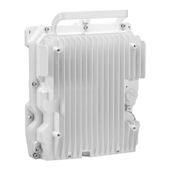
PTP 820C HP Hardware Overview PTP 820C HP Hardware Overview PTP 820C HP features an all-outdoor dual-carrier architecture consisting of a single unit. Figure 1 PTP 820C HP Rear View (Left) and Front View (Right) Figure 2 Cable Gland Construction... -
Page 26: Ptp 820C Hp Interfaces
Chapter 2: PTP 820C HP Overview PTP 820C HP Hardware Overview PTP 820C HP Interfaces Figure 3 PTP 820C HP Interfaces • Power Interface (-48V) • Data Port 1 for GbE traffic: Electric 10/100/1000Base-T (RJ-45) • Data Port 2 for GbE traffic: Optical 1000Base-X (SFP) •... -
Page 27: System Components - Diplexer-Based Branching
System Components – Diplexer-Based Branching Note Refer to the product roadmap for availability of PTP 820C HP in a specific band, as well as the availability of any specific mediation device. Presenting a specific component in this manual does not indicate that it is available for ordering. -
Page 28: Diplexer-Based Branching - Branching Components
Chapter 2: PTP 820C HP Overview System Components – Diplexer-Based Branching Diplexer-Based Branching – Branching Components Figure 6 OMT Figure 7 Space Diversity Branching Device phn-4794_002v000 Page 2-12... -
Page 29: Figure 8 Splitter
Chapter 2: PTP 820C HP Overview System Components – Diplexer-Based Branching Figure 8 Splitter Figure 9 Dual Coupler/Splitter/Circulator phn-4794_002v000 Page 2-13... -
Page 30: Diplexer-Based Branching - Accessory Components
Chapter 2: PTP 820C HP Overview System Components – Diplexer-Based Branching Diplexer-Based Branching – Accessory Components Figure 10 Remote Pole Mount Figure 11 Remote Pole Mount Adaptor phn-4794_002v000 Page 2-14... -
Page 31: System Components - Channel Filter-Based Branching
System Components – Channel Filter-Based Branching Note Refer to the product roadmap for availability of PTP 820C HP in a specific band, as well as the availability of any specific mediation device. Presenting a specific component in this manual does not indicate that it is available for ordering. -
Page 32: Figure 12 Ptp 820C Hp Ocu Unit
Chapter 2: PTP 820C HP Overview System Components – Channel Filter-Based Branching Figure 12 PTP 820C HP OCU Unit Figure 13 PTP 820C HP Branching Pole Profile (Part of PTP 820C HP Filters Remote Mount Kit) Rail Body phn-4794_002v000 Page 2-16... -
Page 33: Figure 14: Short U-Bend
Chapter 2: PTP 820C HP Overview System Components – Channel Filter-Based Branching Figure 14: Short U-Bend Figure 15: Long U-Bend Figure 16: Splitter/Coupler Figure 17: Termination phn-4794_002v000 Page 2-17... -
Page 34: Figure 18 Radio Unit And Diplexer Unit
System Components – Channel Filter-Based Branching Figure 18 Radio Unit and Diplexer Unit In PTP 820C HP, Port 1 is the upper port, located closest to the handle, and Port 2 is the lower port, located closest to the Ethernet ports. -
Page 35: Ptp 820C Hp Models
PTP 820C HP Models Note Refer to the product roadmap for availability of PTP 820C HP in a specific band, as well as the availability of any specific mediation device. Presenting a specific component in this manual does not indicate that it is available for ordering. -
Page 36: Table 2: Ptp 820C Hp Diplexer Unit Model Placeholders
Chapter 2: PTP 820C HP Overview PTP 820C HP Models Table 2: PTP 820C HP Diplexer Unit Model Placeholders Description N060082L218A PTP 820C-HP/RFU-D-HP, Diplexer,L6 GHz, TR 252A, CH1W4, Hi,6179.415-6304.015MHz N060082L219A PTP 820C-HP/RFU-D-HP, Diplexer,L6 GHz, TR 252A, CH1W4, Lo,5927.375-6051.975MHz N060082L229A PTP 820C-HP/RFU-D-HP, Diplexer,L6 GHz, TR 252A, CH3W6, Hi,6238.715-6363.315MHz N060082L230A PTP 820C-HP/RFU-D-HP, Diplexer,L6 GHz, TR 252A, CH3W6, Lo,5986.675-6111.275MHz... - Page 37 Chapter 2: PTP 820C HP Overview PTP 820C HP Models N110082L132A PTP 820C-HP/RFU-D-HP, Diplexer,11 GHz, TR 500, CH3W8, Lo,10775-11035MHz N110082L133A PTP 820C-HP/RFU-D-HP, Diplexer,11 GHz, TR 500, CH4W9, Hi,11305-11585MHz N110082L134A PTP 820C-HP/RFU-D-HP, Diplexer,11 GHz, TR 500, CH4W9, Lo,10815-11095MHz N110082L135A PTP 820C-HP/RFU-D-HP, Diplexer,11 GHz, TR 500, CH5W10, Hi,11345-11605MHz...
-
Page 38: Models For Mediation Devices In Diplexer-Based Branching
Chapter 2: PTP 820C HP Overview PTP 820C HP Models Models for Mediation Devices in Diplexer-Based Branching Table 3: Models for Mediation Devices (Diplexer-Based Branching) Description N000082L166A PTP 820C-HP/RFU-D-HP Remote Mount kit N060082L231A PTP 820C-HP/RFU-D-HP Remote Mount Adaptor,6 GHz N110082L144A... -
Page 39: Models For Mediation Devices In Channel Filter-Based Branching
Models for Mediation Devices in Channel Filter-Based Branching The following is a list of PTP 820C HP Channel Filter Branching units. These Branching units are used to build various PTP 820C HP configurations. Since the SKU is frequency dependent, please check with Cambium Sales Reprsenttive for P/N. -
Page 40: Adaptors And Installation Kits
Chapter 2: PTP 820C HP Overview Adaptors and Installation Kits Adaptors and Installation Kits Table 5: Adaptors and Installation Kits Description 6 GHz 7/8 GHz 11 GHz DUAL COUPLER KIT N060082L22 N070082L342A N110082L142 DUAL SPLITTER KIT N060082L22 N070082L343A N110082L143 DUAL CIRCULATOR KIT... -
Page 41: Antenna Connection
Chapter 2: PTP 820C HP Overview Adaptors and Installation Kits Antenna Connection PTP 820C HP can be mounted directly for 6 to 11 GHz using the following antenna types (for integrated antennas, specific antennas are required): • CommScope: VHLP series •... -
Page 42: Power Specifications
Chapter 2: PTP 820C HP Overview Power Specifications Power Specifications Electrical Requirements • -48V DC Nominal • Maximum current rating 4A • Maximum Cable length 300 meter Power Connection Options Power Source Data Connection Connection DC Cable Type / and Range... -
Page 43: Environmental Specifications
Chapter 2: PTP 820C HP Overview Environmental Specifications Environmental Specifications Operating: ETSI EN 300 019-1-4 Class 4.1 Temperature range for continuous operating temperature with high reliability: -33°C (-27°F) to +55°C (131°F) Temperature range for exceptional temperatures; tested successfully, with limited margins: -45°C (-49°F) to +60°C (140°F) -
Page 44: Chapter 3: Grounding The Ptp 820C Hp Unit
Metric offset wrench key wrench #3 • Metric wrench 10mm Procedure On the front of each PTP 820C HP unit, loosen the nut, plain washer, and serrated washer from the GND stud, using the metric offset hexagon key and the wrench. phn-4794_002v000 Page 3-1... - Page 45 Chapter 3: Grounding the PTP 820C HP Unit Environmental Specifications 2 Place the cable lug (supplied with the PTP 820C HP grounding kit) in place on the screw. 3 Secure the cable lug. 4 The second side of the GND cable should be connected to the main ground bar or terminal ground bar of the site.
-
Page 46: Chapter 4: Cable Installation And Grounding
Chapter 4: Cable Installation and Grounding Environmental Specifications Chapter 4: Cable Installation and Grounding This chapter describes the PTP 820C HP cable installation and grounding procedure. This chapter includes: • Minimum and Maximum Cable Diameter • Cable Grounding • Surge Protection •... -
Page 47: Minimum And Maximum Cable Diameter
To fit the gland, the outer cable diameter should be between 6-10 mm. This applies to all glands on both the PTP 820C HP unit and the PoE Injector. To fit the grounding clamp, the outer diameter of CAT5E Ethernet Cables must be between 6-7.1mm. -
Page 48: Cable Grounding
Chapter 4: Cable Installation and Grounding Cable Grounding Cable Grounding Cables must be grounded as follows: • For fiber cables (see Connecting an Optical Fiber Cable and SFP), no grounding is required. • For DC power cables (see connecting a DC power cable), no grounding is required. - Page 49 Chapter 4: Cable Installation and Grounding Cable Grounding Procedure Strip the Cable jacket. Place the cable in the middle of the grounding bracket. Close the grounding bracket around the cable. Tighten the two screws to secure the grounding bracket around the cable. phn-4794_002v000 Page 4-6...
- Page 50 Chapter 4: Cable Installation and Grounding Cable Grounding Install the grounding lug on the grounding bar, or directly to the tower. Tighten the grounding lug phn-4794_002v000 Page 4-7...
-
Page 51: Power Source
The power supply must have grounding points on the AC and DC sides. Caution The user power supply GND must be connected to the positive pole in the PTP 820C HP power supply. Any other connection may cause damage to the system. -
Page 52: Surge Protection
Surge Protection Surge Protection PTP 820C HP includes built-in surge protection for its Ethernet and power interfaces. PTP 820C HP’s surge protection implementation complies with the standards set forth in the Surge Protection Requirements section of the PTP 820C HP Technical Description, provided the Ethernet cables were prepared according to the instructions in Connecting the Ethernet Cable. -
Page 53: Available Cable Options
Chapter 4: Cable Installation and Grounding Available Cable Options Available Cable Options Fiber Optic Cables - Single Mode Table 11: Fiber Optic Cables - Single Mode part numbers Part Number Description N000082L139A PTP 820 Optical CABLE, SM, 30m N000082L140A PTP 820 Optical CABLE, SM, 50m N000082L141A PTP 820 Optical CABLE, SM, 80m N000082L142A... -
Page 54: Cables For Mimo Connections
Chapter 4: Cable Installation and Grounding Available Cable Options Cables for MIMO Connections Table 14: Cables for MIMO Connections Part Number Description N000082L063A PTP 820 C, CABLE, SFP,4x4MIMO_DATA_SHARING_KIT_10M N000082L138A PTP 820 C, CABLE, SFP,4x4MIMO_DATA_SHARING_KIT_20M N000082L064A PTP 820 C, SOURCE_SHARING_10M N000082L137A PTP 820 C, SOURCE_SHARING_20M N000082L060A PTP 820 C MIMO or Prot management cable 10m... -
Page 55: Figure 20 Cable Design
Chapter 4: Cable Installation and Grounding Available Cable Options Figure 20 Cable design • [1] Conductor • [2] Insulation • [3] Screen: Alu/Pet foil. Alu outside • [4] Tinned copper braid • [5] Jacket Table 16: Ethernet cable Color Code Pair Wire A Wire B... -
Page 56: Outdoor Ethernet Cable Specifications
Chapter 4: Cable Installation and Grounding Available Cable Options Outdoor Ethernet Cable Specifications Table 17: Ethernet Cable Electrical Requirements Electrical Requirements Cable type CAT-5e SFUTP, 4 pairs, according to ANSI/TIA/EIA- 568-B-2 Wire gauge 24 AWG Stranding Solid Voltage rating Shielding Braid + Foil Pinout Ethernet Cable Mechanical/ Environmental Requirements... - Page 57 Chapter 4: Cable Installation and Grounding Available Cable Options Wire gauge 14 AWG (for <328ft installations) 9 AWG (for >328ft installations) Stranding stranded Voltage rating 600V for 9 AWG 300V for 14 AWG Spark test Dielectric strength 2KV AC min Mechanical/ Environmental Requirements Jacket PVC, double, UV resistant...
-
Page 58: Securing The Cables
Chapter 4: Cable Installation and Grounding Securing the Cables Securing the Cables All cables should be secured at every meter on-site using either a T-Rups kit, Model “Outdoor Ties”, or cable clamps. When using the T-Rups kit, take special care to apply the proper amount of force in order to avoid damage to the cable. -
Page 59: Special Instructions For Use Of Glands
Special Instructions for use of Glands Special Instructions for use of Glands Note Each PTP 820C HP unit is supplied with two glands. If additional glands are required, they must be ordered separately, in kits of five glands each. Table 19: Glands kit... -
Page 60: General Installation Procedure
Chapter 4: Cable Installation and Grounding Special Instructions for use of Glands General Installation Procedure This procedure applies to all cable types and explains how to install the cables using long glands. The gland is supplied assembled. Before inserting a cable, you must disassemble the gland cap and gland rubber from the gland body. - Page 61 Chapter 4: Cable Installation and Grounding Special Instructions for use of Glands Optionally, after securing the cable into the body of the gland, close the other side of the gland with an M28 gland cap. The gland cap protects the cable and connector from damage when elevating the cable and gland to the radio unit.
- Page 62 Chapter 4: Cable Installation and Grounding Special Instructions for use of Glands Note Before tightening the gland, make sure the gland is aligned with the taped hole in the unit. Tightening the gland at an angle can ruin the thread on the gland and prevent proper sealing of the interface.
- Page 63 Chapter 4: Cable Installation and Grounding Special Instructions for use of Glands Tighten the rear portion of the gland onto the main part of the gland and make sure that the main part of the gland does not have an additional swivel after the rear portion is secured. Note If the main portion of the gland is rotated while the rear portion is seizing the cable, this may ruin the cable connector.
-
Page 64: Connecting An Optical Fiber Cable And Sfp
Chapter 4: Cable Installation and Grounding Connecting an Optical Fiber Cable and SFP Connecting an Optical Fiber Cable and SFP To connect an optical fiber cable and the SFP transceiver: Use a pre-assembled cable. Split the connector into two separate LC Connectors (one for each fiber). Remove the gland cap and rubber from the gland body. - Page 65 Remove the tie wrap securing the cable to the gland. Note A new tie wrap must be used to secure the cable to the gland at the end of the procedure, as described in Step 13. Connect the connector into the PTP 820C HP LC connector. phn-4794_002v000 Page 4-22...
- Page 66 Chapter 4: Cable Installation and Grounding Connecting an Optical Fiber Cable and SFP Tighten the gland to the radio unit until there is full contact between the gland and the radio unit. Tighten the gland cap. Note Before tightening the gland, ensure it is aligned with the taped hole in the unit. Tightening the gland at an angle can ruin the thread on the gland and prevent proper sealing of the interface Tighten the gland gently and make sure there is no resistance.
- Page 67 Chapter 4: Cable Installation and Grounding Connecting an Optical Fiber Cable and SFP phn-4794_002v000 Page 4-24...
-
Page 68: Connecting A Dc Power Cable
Chapter 4: Cable Installation and Grounding Connecting a DC Power Cable Connecting a DC Power Cable Note The DC power cable and connector must be ordered separately. See DC Cable and Connector. To connect a DC power cable: Strip off 45 mm from the cable jacket. Expose 10 mm at the edge of each of the two wires. - Page 69 Chapter 4: Cable Installation and Grounding Connecting a DC Power Cable Tighten the two top screws. Plug the power cable with connector into the PTP 820C HP power connector. phn-4794_002v000 Page 4-26...
- Page 70 Chapter 4: Cable Installation and Grounding Connecting a DC Power Cable Tighten the two front screws. Screw the gland into the radio unit Caution Before tightening the gland, make sure the gland is even with the cover. Tighten the gland gently and make sure there is no resistance.
-
Page 71: Connecting The Ethernet Cable
Chapter 4: Cable Installation and Grounding Connecting the Ethernet Cable Connecting the Ethernet Cable If you need to assemble the Ethernet cable, follow the instructions in section Preparing the Ethernet Cable and Plug-in Field, then proceed to section Connection of Ethernet Cable to PTP 820C If you using a pre-assembled Ethernet cable, follow the instructions in section Preparing the Ethernet Cable Already... - Page 72 Chapter 4: Cable Installation and Grounding Connecting the Ethernet Cable Roll back the foil shield insulation and wrap the drain wire around the foil. Do not remove any insulation from the conductors. Align the colored wires. Note Cord colors should be matched to the same pins on both ends of the cable Trim all wires to the same length.
-
Page 73: Preparing The Ethernet Cable Already Assembled
Chapter 4: Cable Installation and Grounding Connecting the Ethernet Cable Caution To ensure proper grounding, it is essential that the twisted braid be firmly connected to the RJ45 plug. Crimp the RJ45 plug with the crimp tool. Make sure the twisted braid is crimped firmly to the RJ45 plug. -
Page 74: Connection Of Ethernet Cable To Ptp 820C Hp
Connection of Ethernet Cable to PTP 820C HP To connect the Ethernet cable to the PTP 820C HP: Remove the relevant cap from the PTP 820C HP radio. You can use the side of the gland to unscrew the cap. - Page 75 Chapter 4: Cable Installation and Grounding Connecting the Ethernet Cable Screw the gland into the radio unit. Caution Before tightening the gland, make sure the gland is even with the cover. Tighten the gland gently and make sure there is no resistance. If there is resistance, stop immediately and verify that the gland is not being inserted at an angle.
- Page 76 Chapter 4: Cable Installation and Grounding Connecting the Ethernet Cable Secure the cable to the gland using a tie wrap. phn-4794_002v000 Page 4-33...
-
Page 77: Management Connection For 1+1/2+2 Hsb Configurations
Management Connection for 1+1/2+2 HSB Configurations In 4x4 MIMO and all HSB protection configurations, two Y-splitter cables and a special signaling cable must be used to connect the management ports (MGT/PROT) of the two PTP 820C HP units and provide management access to each unit. -
Page 78: Figure 22 4X4 Mimo Or Hsb Protection Configuration With External Management
“MIMO/Prot” port of the second splitter on the mate PTP 820C HP unit. The following figure demonstrates a 4x4 MIMO configuration in which both PTP 820C HP units are connected to an external management station and to each other, using two splitters. -
Page 79: Chapter 5: Generic Installation Procedures And Notes
Chapter 5: Generic Installation Procedures and Notes Management Connection for 1+1/2+2 HSB Configurations Chapter 5: Generic Installation Procedures and Notes This chapter describes the generic nstallation procedure and notes for PTP 820C HP. This chapter includes: • General Notes Concerning All Installation Procedures... -
Page 80: General Notes Concerning All Installation Procedures
2+0 SP installation, if you want to install a 1+0 SP HW ready for 2+0 One of the major benefits of the PTP 820C HP and the dual core architecture is that upgrading can be done remotely by uploading the correct software license. -
Page 81: Chapter 6: Installation Instructions For Configurations With Diplexer-Based Branching
Chapter 6: Installation Instructions for Configurations with Diplexe Torque Requirements Based Branching Chapter 6: Installation Instructions for Configurations with Diplexer-Based Branching Torque Requirements When tightening the captive screws, use 20 Nm torque for radio-antenna, radio-mediation device, and mediation device-antenna connections. In order to avoid misalignment, screws should be tightened progressively. -
Page 82: General Radio Installation
In most cases, the Diplexers unit should be attached to the antenna or mediation device first. Then, attach the radio unit to the Diplexers unit. The PTP 820C HP radio can be assembled to the diplexers kit prior to installation, then mounted to the antenna or mediation device as a single unit. For details, see Installing the Diplexer on the Radio. -
Page 83: Figure 25 Ptp 820C Hp Installation - Attaching The Diplexers Unit Before The Radio Unit
Chapter 6: Installation Instructions for Configurations with Diplexe Torque Requirements Based Branching Figure 25 PTP 820C HP Installation – Attaching the Diplexers Unit Before the Radio Unit phn-4794_002v000 Page 6-5... -
Page 84: Installing The Diplexer On The Radio
Based Branching Installing the Diplexer on the Radio The PTP 820C HP is delivered as two separate components: a generic radio unit and a diplexer unit. This section explains how to attach the diplexer unit to the radio unit. Note Mounting of the diplexer unit to the radio unit should be performed by certified personnel in a clean, temperature and humidity-controlled environment. -
Page 85: Figure 26 Fitting The Diplexer Unit To The Radio Unit - Radio Side
Chapter 6: Installation Instructions for Configurations with Diplexe Torque Requirements Based Branching Figure 26 Fitting the Diplexer Unit to the Radio Unit - Radio Side Figure 27 Fitting the Diplexer Unit to the Radio Unit - Diplexer Unit Side phn-4794_002v000 Page 6-7... -
Page 86: Figure 28 Radio And Diplexer Units Together
Chapter 6: Installation Instructions for Configurations with Diplexe Torque Requirements Based Branching Figure 28 Radio and Diplexer Units Together Figure 29 Hook and Carrying Handle phn-4794_002v000 Page 6-8... -
Page 87: Figure 30 Securing The Diplexer Unit To The Radio Unit
Figure 38. Then strongly tighten the screws in the same order. Figure 30 Securing the Diplexer Unit to the Radio Unit 5 Proceed to install the PTP 820C HP in the desired configuration, as described in the following sections. phn-4794_002v000... -
Page 88: Chapter 7: Ptp 820C Hp Detailed Configurations Description
Chapter 7: PTP 820C HP Detailed Configurations Description Installing the Diplexer on the Radio Chapter 7: PTP 820C HP Detailed Configurations Description This chapter describes the PTP 820C HP detailed configuration description. This chapter includes: • 2+0 Dual Polarization Direct Mount •... -
Page 89: 2+0 Dual Polarization Direct Mount
Chapter 7: PTP 820C HP Detailed Configurations Description 2+0 Dual Polarization Direct Mount 2+0 Dual Polarization Direct Mount Note This procedure can also be used for 1+0 DP HW ready for 2+0 DP configuration. List of Items Item Description Quantity... -
Page 90: Procedure
Chapter 7: PTP 820C HP Detailed Configurations Description 2+0 Dual Polarization Direct Mount Procedure Prior to the installation, follow the antenna manufacturer’s instructions to use the circular adaptor. (Remove the existing rectangular transition, swap the O-ring, and install the circular transition instead.) - Page 91 Chapter 7: PTP 820C HP Detailed Configurations Description 2+0 Dual Polarization Direct Mount Connect the PTP 820C HP radio/dual coupler to the OMT kit using the four M8 captive screws and washers supplied and tighten the screws. Important: Verify that the O-rings are properly mounted between the OMT ports and the radio.
-
Page 92: 2+0 Dual Polarization Remote Mount
Chapter 7: PTP 820C HP Detailed Configurations Description 2+0 Dual Polarization Remote Mount 2+0 Dual Polarization Remote Mount This procedure is for use with Interface antennas, up to six feet. For standard interface antennas (six feet and larger), no OMT and no Circ./Circ. Adaptor are used, and the flexible waveguides are connected directly to the antenna flanges. -
Page 93: List Of Items
Chapter 7: PTP 820C HP Detailed Configurations Description 2+0 Dual Polarization Remote Mount List of Items Item Description Quantity Remarks Models for PTP 820C HP Radio Unit Radio Unit Models for PTP 820C HP Diplexer Unit Diplexer Unit PTP 820C HP OMT Kit... - Page 94 2+0 Dual Polarization Remote Mount Important: Verify that the O-ring is properly mounted between the antenna transition and the OMT. 3 Mount and tighten the Remote MountAdapter to the PTP 820C HP OMT ports using the screws supplied with the adapter kit:...
-
Page 95: Figure 31 6 Ghz - Mounting The First Adaptor
Important: Verify that the O-rings are correctly mounted between the OMT ports and each flexible waveguide. 5 Mount and tighten the PTP 820C HP DC pole mount to the pole using the four washers and screws supplied with the PTP 820C HP DC pole mount kit. -
Page 96: Figure 32 Remote Pole Mount Kit- 6-11 Ghz
6 Mount and tighten the PTP 820C HP Remote Mount Adaptor plate (supplied in PTP 820C HP Adaptor Remote Mount kit) to the PTP 820C HP Pole Mount using the four flat screws supplied with thePTP 820C HP Adaptor Remote Mount kit. -
Page 97: Figure 34 Remote Pole Mount Kit - 6-11 Ghz
Figure 34 Remote Pole Mount Kit – 6-11 GHz Figure 35 Remote Pole Mount Kit – 4-5 GHz Mount and tighten the PTP 820C HP Radio to the PTP 820C HP Pole Mount using the four flat screws supplied with the PTP 820C HP Radio. - Page 98 Chapter 7: PTP 820C HP Detailed Configurations Description 2+0 Dual Polarization Remote Mount Mount and tighten both Flexible WGs with their O-ring to the PTP 820C HP Remote Mount Adaptor ports using the four screws supplied with each Flexible WG kit.
-
Page 99: 2+0 Single Polarization Direct Mount
Chapter 7: PTP 820C HP Detailed Configurations Description 2+0 Single Polarization Direct Mount 2+0 Single Polarization Direct Mount Note This procedure can also be used for 1+0 SP HW ready for 2+0 SP configuration. List of Items Item Description Quantity... - Page 100 2+0 Single Polarization Direct Mount For vertical polarization, locate the twist with the letter “V” on top. 2 Mount and tighten the PTP 820C HP Splitter Kit on the antenna using the four M8 screws and washers. Important: Verify that the O-ring is properly mounted between the antenna transition and the splitter.
- Page 101 Chapter 7: PTP 820C HP Detailed Configurations Description 2+0 Single Polarization Direct Mount 3 Connect the PTP 820C HP DC radio to the splitter kit using the four M8 captive screws and washers supplied, and tighten the screws. Important: Verify that the O-rings are properly mounted between the OMT ports and the radio/dual coupler.
-
Page 102: 2+2 Hsb Double Polarization Direct Mount
Chapter 7: PTP 820C HP Detailed Configurations Description 2+2 HSB Double Polarization Direct Mount 2+2 HSB Double Polarization Direct Mount Note This procedure can also be used for 2 x 1+1 HSB DP HW ready for 2+2 HSB DP configurations. - Page 103 Chapter 7: PTP 820C HP Detailed Configurations Description 2+2 HSB Double Polarization Direct Mount 2 Connect the PTP 820C HP OMT Kit to the antenna and secure it with four screws. Verify existence of the O-ring. Important: Verify that the O-ring is properly mounted between the antenna transition and the OMT.
- Page 104 Important: Verify that the O-rings are properly mounted between the OMT ports and the dual coupler 4 Mount and tighten the PTP 820C HP DC radio unit to both sides of the Dual Coupler Kit using the supplied captive screws and washers. Pay attention that the O-rings are correctly mounted on the radio ports of the PTP 820C HP Dual Coupler.
- Page 105 Chapter 7: PTP 820C HP Detailed Configurations Description 2+2 HSB Double Polarization Direct Mount Connect the MIMO signaling cable between the management ports of both units. For additional instructions on preparing and connecting this cable, refer to Preparing a MIMO/Protection Signaling Cable.
-
Page 106: 2+2 Hsb Double Polarization Remote Mount
Chapter 7: PTP 820C HP Detailed Configurations Description 2+2 HSB Double Polarization Remote Mount 2+2 HSB Double Polarization Remote Mount Note This procedure can also be used for 2x 1+1 HSB DP HW ready for 2+2 HSB DP configurations. List of Items... -
Page 107: Procedure
Chapter 7: PTP 820C HP Detailed Configurations Description 2+2 HSB Double Polarization Remote Mount Procedure Prior to the installation, follow the antenna manufacturer’s instructions to use the circular adaptor. (Remove the existing rectangular transition, swap the O-ring, and install the circular transition instead.) - Page 108 Chapter 7: PTP 820C HP Detailed Configurations Description 2+2 HSB Double Polarization Remote Mount Mount and tighten the Remote Mount Adapter to the PTP 820C HP OMT ports using the screws supplied with the adapter kit: Mount and tighten the O-ring and the flexible waveguide to the adapter ports using the screws supplied with the flexible waveguide kit.
- Page 109 Important:Verify that the O-rings are correctly mounted between the OMT ports and each flexible waveguide. Mount and tighten the PTP 820C HP DC pole mount to the pole using the four washers and screws supplied with the PTP 820C HP DC pole mount kit. See Steps 5 and 6 in...
- Page 110 Remote Mount kit) to the PTP 820C HP Pole Mount using the four flat screws supplied with the PTP 820C HP Adaptor Remote Mount kit. Mount and tighten the PTP 820C HP Radio to the PTP 820C HP Pole Mount using the four flat screws supplied with the PTP 820C HP Radio.
- Page 111 2+2 HSB Double Polarization Remote Mount Mount and tighten the PTP 820C HP Dual Coupler to the PTP 820C HP Pole Mount using the four screws and washers that are supplied with the PTP 820C HP Dual Coupler kit. Pay attention that the O-rings are mounted on the PTP 820C HP Remote Mount Adaptor.
- Page 112 2+2 HSB Double Polarization Remote Mount Mount and tighten the PTP 820C HP radios on each side of the PTP 820C HP Dual Coupler using the screws assembled on PTP 820C HP radio. Payattention that the O-rings are correctly assembled on the radio port of the PTP 820C HP Dual coupler.
- Page 113 2+2 HSB Double Polarization Remote Mount 10 Connect both Flexible Waveguides and Sealing Gaskets supplied with each Flexible Waveguide Kit to the PTP 820C HP Dual Coupler antenna ports. Tighten the screws and washers supplied with the Flexible Waveguide Kit.
-
Page 114: 2+2 Hsb Single Polarization Direct Mount
Chapter 7: PTP 820C HP Detailed Configurations Description 2+2 HSB Single Polarization Direct Mount 2+2 HSB Single Polarization Direct Mount Note This procedure can also be used for 2 x 1+1 HSB SP HW ready for 2+2 HSB SP configurations. - Page 115 Chapter 7: PTP 820C HP Detailed Configurations Description 2+2 HSB Single Polarization Direct Mount For vertical polarization, locate the twist with the letter “V” on top. Page 7-28...
- Page 116 Connect the PTP 820C HP Dual Coupler Kit to the Splitter Kit using four M8 screws and washers, and tighten the screws. 4 Mount and tighten the PTP 820C HP radio unit to both sides of the Dual Coupler Kit using the supplied captive screws and washers. Pay attention that the O-rings are correctly mounted on the radio ports of the PTP 820C HP Dual Coupler.
- Page 117 Chapter 7: PTP 820C HP Detailed Configurations Description 2+2 HSB Single Polarization Direct Mount Connect the protection signaling cable between the management ports of both units. For additional instructions on preparing and connecting this cable, refer to Preparing a MIMO/Protection Signaling Cable.
-
Page 118: X 2+0 Dual Polarization Direct Mount
Chapter 7: PTP 820C HP Detailed Configurations Description 2 x 2+0 Dual Polarization Direct Mount 2 x 2+0 Dual Polarization Direct Mount Note This procedure can also be used for 2+0 DP HW ready for 2 x 2+0 DP configurations. - Page 119 Chapter 7: PTP 820C HP Detailed Configurations Description 2 x 2+0 Dual Polarization Direct Mount 2 Connect the PTP 820C HP OMT Kit to the antenna and secure it with four screws. Verify existence of the O-ring. Page 7-32...
- Page 120 3 Connect the PTP 820C HP Dual Coupler Kit to the OMT Kit using four M8 screws and washers, and tighten the screws. 4 Mount and tighten the PTP 820C HP DC radio unit to both sides of the Dual Coupler Kit using the supplied captive screws and washers. Pay attention that the O-rings are correctly mounted on the radio ports of the PTP 820C HP Dual Coupler.
-
Page 121: X 2+0 Dual Polarization Remote Mount
Chapter 7: PTP 820C HP Detailed Configurations Description 2 x 2+0 Dual Polarization Remote Mount 2 x 2+0 Dual Polarization Remote Mount Note This procedure can also be used for 2 x 1+0 DP HW ready for 2 x 2+0 DP configurations. -
Page 122: Procedure
2 Connect the OMT kit to the antenna and secure it with four screws. Important: Verify that the O-ring is properly mounted between the antenna transition and the OMT. 3 Mount and tighten the appropriate adapter to the PTP 820C HP OMT ports using the screws supplied with the adapter kit: •... -
Page 123: Figure 36 6 Ghz - Mounting The First Adaptor
Chapter 7: PTP 820C HP Detailed Configurations Description 2 x 2+0 Dual Polarization Remote Mount Figure 36 6 GHz – Mounting the First Adaptor Figure 37 6 GHz – Mounting the Second Adaptor Page 7-36... -
Page 124: Figure 38 Mounting The Single Adaptor For 7, 8, 10, And 11 Ghz
Chapter 7: PTP 820C HP Detailed Configurations Description 2 x 2+0 Dual Polarization Remote Mount • For 7, 8, 10, and 11 GHz, there is a single adaptor: Figure 38 Mounting the Single Adaptor for 7, 8, 10, and 11 GHz 4 Mount and tighten the O-ring and the flexible waveguide to the adapter ports using the screws supplied with the flexible waveguide kit. - Page 125 Chapter 7: PTP 820C HP Detailed Configurations Description 2 x 2+0 Dual Polarization Remote Mount 5 Mount and tighten the PTP 820C HP DC pole mount to the pole using the four washers and screws supplied with the PTP 820C HP DC pole mount kit.
- Page 126 Chapter 7: PTP 820C HP Detailed Configurations Description 2 x 2+0 Dual Polarization Remote Mount 7 Mount and tighten the PTP 820C HP Radio to the PTP 820C HP Pole Mount using the four flat screws supplied with the PTP 820C HP Radio.
-
Page 127: X 2+0 Single Polarization Direct Mount
Chapter 7: PTP 820C HP Detailed Configurations Description 2 x 2+0 Single Polarization Direct Mount 2 x 2+0 Single Polarization Direct Mount Note This procedure can also be used for 2 x 1+0 SP HW ready for 2 x 2+0 SP configurations. - Page 128 Chapter 7: PTP 820C HP Detailed Configurations Description 2 x 2+0 Single Polarization Direct Mount • For vertical polarization, locate the twist with the letter “V” on top. Page 7-41...
- Page 129 2 Mount the Dual Core Kit on the antenna using four M8 screws and washers and tighten the screws. Connect the PTP 820C HP Dual Coupler Kit to the Splitter Kit using four M8 screws and washers, and tighten the screws.
- Page 130 2 x 2+0 Single Polarization Direct Mount 4 Mount and tighten the PTP 820C HP DC radio unit to both sides of the Dual Coupler Kit using the supplied captive screws and washers. Pay attention that the O-rings are correctly mounted on the radio ports of the PTP 820C HP Dual Coupler.
-
Page 131: 2+2 Hsb Single Polarization Remote Mount
Chapter 7: PTP 820C HP Detailed Configurations Description 2+2 HSB Single Polarization Remote Mount 2+2 HSB Single Polarization Remote Mount Note This procedure can also be used for 1+1HSB SP HW ready for 2+2HSB SP configurations. ACCP - Protected List of Items... - Page 132 PTP 820C HP Adaptor Remote Mount kit. Mount and tighten the PTP 820C HP Splitter to the PTP 820C HP Pole Mount using the four captive screws and washers that are assembled to the PTP 820C HP Splitter kit.
- Page 133 Chapter 7: PTP 820C HP Detailed Configurations Description 2+2 HSB Single Polarization Remote Mount Attach the Diplexer unit to the Dual Coupler using 8 M4 screws provided with the Diplexer kit, as shown below, using 20Nm torque. Page 7-46...
- Page 134 Chapter 7: PTP 820C HP Detailed Configurations Description 2+2 HSB Single Polarization Remote Mount Note Tighten the screws diagonally. First begin to fasten the upper right screw of the top Diplexer and then the lower left screw of the bottom Diplexer, then fasten the upper left screw of the top Diplexer and then the lower right screw of the bottom Diplexer.
- Page 135 Chapter 7: PTP 820C HP Detailed Configurations Description 2+2 HSB Single Polarization Remote Mount Location Pin Hole (Not Shown) Location Location Location Pin Pin Hole (Not Shown) 8 M5 Captive Screws Repeat steps 4-6 to attach the second Diplexer unit and the second Radio unit to the other side of the Dual Coupler, Dual Splitter, or Dual Circulator.
-
Page 136: 2X2 Los Mimo Direct Mount
Chapter 7: PTP 820C HP Detailed Configurations Description 2x2 LoS MIMO Direct Mount 2x2 LoS MIMO Direct Mount Note This procedure can also be used for 1+0 SD configurations. List of Items Item Description Quantity Model PTP 820C HP RADIO... - Page 137 Chapter 7: PTP 820C HP Detailed Configurations Description 2x2 LoS MIMO Direct Mount For vertical polarization, locate the twist with the letter “V” on top. Page 7-50...
- Page 138 2 Mount the Splitter Kit on the antenna using four M8 screws and washers and tighten the screws. 3 Connect the PTP 820C HP DC radio to the Splitter kit using the four M8 captive screws and washers supplied and tighten the screws.
-
Page 139: 2X2 Los Mimo Remote Mount
Chapter 7: PTP 820C HP Detailed Configurations Description 2x2 LoS MIMO Remote Mount 2x2 LoS MIMO Remote Mount Note This procedure can also be used for 1+0 SD configurations. List of Items Item Description Quantity Model PTP 820C HP RADIO... -
Page 140: Procedure
820C HP Adaptor Remote Mount kit. 2 Mount and tighten the PTP 820C HP Radio to the PTP 820C HP Pole Mount using the four captive screws and washers that are supplied with the PTP 820C HP Radio. Pay attention that the O-rings are mounted on the PTP 820C HP Remote Mount Adaptor. - Page 141 Chapter 7: PTP 820C HP Detailed Configurations Description 2x2 LoS MIMO Remote Mount 3 Mount and tighten both Flexible WGs with their O-ring to the PTP 820C HP Remote Mount Adaptor ports using the four screws supplied with each Flexible WG kit.
-
Page 142: 4X4 Los Mimo Direct Mount
Chapter 7: PTP 820C HP Detailed Configurations Description 4x4 LoS MIMO Direct Mount 4x4 LoS MIMO Direct Mount Notes 1) This procedure can also be used for 2+0 SP HW ready for 2 x 2+0 SP configurations. 2) This procedure can also be used for 2+2 SD configurations. -
Page 143: Procedure
Chapter 7: PTP 820C HP Detailed Configurations Description 4x4 LoS MIMO Direct Mount Procedure For instructions on installation of the PTP820C OMT and radios, see 2+0 Dual Polarization Direct Mount. 2 Connect the source sharing cable between both EXT REFPTP 820C HP radio connectors. The maximum torque for connecting this cable to the radio is 5Lb.in (0.5N.m). - Page 144 Chapter 7: PTP 820C HP Detailed Configurations Description 4x4 LoS MIMO Direct Mount 4 Connect the MIMO signaling cable between the management ports of both units. For additional instructions on preparing and connecting this cable, refer to Preparing a MIMO/Protection Signaling Cable.
-
Page 145: 4+0 Single/Dual Polarization Direct Mount
Chapter 7: PTP 820C HP Detailed Configurations Description 4+0 Single/Dual Polarization Direct Mount 4+0 Single/Dual Polarization Direct Mount List of Items Item Description Quantity Remarks Models for PTP 820C HP Radios Radio Unit Models for Diplexer Unit PTP 820C HP Diplexer Units... - Page 146 Chapter 7: PTP 820C HP Detailed Configurations Description 4+0 Single/Dual Polarization Direct Mount For vertical polarization, locate the twist with the letter “V” on top. Page 7-59...
- Page 147 Mount and tighten the PTP 820C HP radio unit to both sides of the Dual Coupler Kit using the supplied captive screws and washers. Pay attention that the O-rings are correctly mounted on the radio ports of the PTP 820C HP Dual Coupler.
- Page 148 Chapter 7: PTP 820C HP Detailed Configurations Description 4+0 Single/Dual Polarization Direct Mount Connect the protection signaling cable between the management ports of both units. For additional instructions on preparing and connecting this cable, refer to Preparing a MIMO/Protection Signaling Cable.
-
Page 149: 4+0 With Dual Circulator Direct Mount
Chapter 7: PTP 820C HP Detailed Configurations Description 4+0 with Dual Circulator Direct Mount 4+0 with Dual Circulator Direct Mount The following example illustrates a typical configuration, assuming that: The regulation specifies a channelization of 8 consecutive 28/38MHz channels (1-8 ch). -
Page 150: 4+0 Dual Polarization, Remote Mount
Chapter 7: PTP 820C HP Detailed Configurations Description 4+0 Dual Polarization, Remote Mount 4+0 Dual Polarization, Remote Mount List of Items Item Description Quantity Remarks Models for PTP 820C HP Radios Radio Unit Models for PTP 820C HP Diplexer Units... - Page 151 Remote Mount. Mount and tighten the PTP 820C HP Dual Coupler to thePTP 820C HP Pole Mount using the four screws and washers that are supplied with the PTP 820C HP Dual Circulator/Splitter kit. Make sure that the O-rings are mounted on the PTP 820C HP Remote Mount Adaptor.
- Page 152 Chapter 7: PTP 820C HP Detailed Configurations Description 4+0 Dual Polarization, Remote Mount Note Tighten the screws diagonally. First begin to fasten the upper right screw of the top Diplexer and then the lower left screw of the bottom Diplexer, then fasten the upper left screw of the top Diplexer and then the lower right screw of the bottom Diplexer.
- Page 153 Chapter 7: PTP 820C HP Detailed Configurations Description 4+0 Dual Polarization, Remote Mount Location Pin Hole (Not Shown) Location Location Location Pin Pin Hole (Not Shown) 8 M5 Captive Screws Repeat steps 4-6 to attach the second Diplexer unit and the second Radio unit to the other side of the Dual Circulator/Splitter.
- Page 154 Chapter 7: PTP 820C HP Detailed Configurations Description 4+0 Dual Polarization, Remote Mount 10. Connect both Flexible Waveguides and Sealing Gaskets supplied with each Flexible Waveguide Kit to the OMT Remote Mount Adaptor using the screws supplied with the Flexible Waveguide kits.
-
Page 155: 4+0 With Dual Circulator Remote Mount
Chapter 7: PTP 820C HP Detailed Configurations Description 4+0 with Dual Circulator Remote Mount 4+0 with Dual Circulator Remote Mount The following example illustrates a typical configuration, assuming that: • The regulation specifies a channelization of 8 consecutive 28/38MHz channels (1-8 ch). -
Page 156: Dual Circulator Multi-Carrier Kit Installation
Mount kit). Tighten the four M10 Hex screws and washers supplied within the kit. 6-8 GHz Mount and tighten the PTP 820C HP MC Dual Cir to the PTP 820C HP pillar adapter bracket using the four M8 Hex screws and washers supplied within the kit. - Page 157 M8 Hex screws and washers supplied within the kit. 2 Mount and tighten the PTP 820C HP MC Dual Cir to the PTP 820C HP MC Extender using the four M8 Hex screws and washers supplied within the kit.
- Page 158 6-11GHz Mount and tighten the PTP 820C HP Dual Cir to each side of the PTP 820 MC Dual Circ using the four M8 Hex screws and washers supplied in the PTP 820 Dual Circ kit. Pay attention that the O-rings on the PTP 820C HP MC Dual Circ are well in place during the mounting.
- Page 159 Dual Circulator Multi-Carrier Kit Installation 3 Mount and tighten the PTP 820C HP MC Remote mount adapter to the PTP 820C HP MC Dual Circ antenna ports using the four screws assembled on the PTP 820C HP radio. Pay attention that the O- rings on the PTP 820C HP MC Remote mount adapter are well in place during the mounting.
- Page 160 Chapter 7: PTP 820C HP Detailed Configurations Description Dual Circulator Multi-Carrier Kit Installation The following example illustrates a typical configuration, assuming: • The regulation specifies a channelization of 8 consecutive 28/30 MHz channels (1-8ch). • The actual channels in use are channels 1, 5.
- Page 161 Chapter 7: PTP 820C HP Detailed Configurations Description Dual Circulator Multi-Carrier Kit Installation Figure 40 4+0 Configuration Low Channels Radio (i.e: Ch1 V&H) Antenna High Channels Ports Radio (i.e: Ch5 V&H) 1 2 3 4 5 6 7 8 High Channels Radio (i.e Ch5 V&H)
-
Page 162: Afr 1+0 Hub Site
HP or PTP 820C HP units are deployed in two tail sites. The hub site utilizes a single PTP 820C HP unit with two radio carriers. Each carrier is in a link, via its own directional antenna, with a tail site that consists of a PTP 820C HP or PTP 820S unit. -
Page 163: Procedure
3 Mount and tighten the PTP 820C HP Remote Mount Adaptor plate (supplied in PTP 820C HP Adaptor Remote Mount kit) to the PTP 820C HP Pole Mount using the four flat screws supplied with the PTP 820C HP Adaptor Remote Mount kit. - Page 164 AFR 1+0 Hub Site 4 Mount and tighten the PTP 820C HP to the PTP 820C HP Pole Mount using the four captive screws and washers that are supplied with the PTP 820C HP. Pay attention that the O-rings are mounted on the PTP 820C HP Remote Mount Adaptor.
- Page 165 Chapter 7: PTP 820C HP Detailed Configurations Description AFR 1+0 Hub Site 5 Mount and tighten both Flexible WGs with their O-ring to the PTP 820C HP Remote Mount Adaptor ports using the four screws supplied with each Flexible WG kit.
-
Page 166: Chapter 8: Installation Instructions For Configurations With Channel Filter-Based Branching
Channel Filter-Based Branching – Component Assembly Assembling the OCU Mounting Kit This section explains how to attach the OCU mounting kit for PTP 820C HP radio units to a 114 mm pole. List of Items Item... -
Page 167: Figure 41 Branching Pole Profile
Chapter 8: Installation Instructions for Configurations with Channe Channel Filter-Based Branching – Component Assembly Filter-Based Branching Figure 41 Branching Pole Profile Figure 42 Branching Pillars (with Screws, Nuts, and Washers) Required Tools • Metric offset wrench key wrench set Procedure Mount and tighten the two Branching Pillars to a pole with a diameter of 114 mm using the four M10x150 screws, four washers, and eight nuts supplied with the OCU Mounting kit. - Page 168 Chapter 8: Installation Instructions for Configurations with Channe Channel Filter-Based Branching – Component Assembly Filter-Based Branching Mount and tighten the Branching Pole to one of the Branching Pillars using the four M10x25 screws supplied with the OCU Mounting kit. Use torque of 45 Nm. Holes for Screws M10x25...
-
Page 169: Assembling The Ocu
Channel Filter-Based Branching – Component Assembly Filter-Based Branching Assembling the OCU List of Items Item Description Quantity Model PTP 820C HP OCU Kit 1 per radio Models for OCU Unit OCU Body 1 per OCU kit Included in OCU kit OCU Rail... -
Page 170: Figure 43 1, 2, 4 - Ocu Kit
Chapter 8: Installation Instructions for Configurations with Channe Channel Filter-Based Branching – Component Assembly Filter-Based Branching Figure 43 1, 2, 4 – OCU Kit (Body, Rail, and M8x25 Screws 3 – PTP 820C HP Radio 4– M8x25 Screw 5 - M8x30 Screw 6– Washers, Plain 7 - Washers, Helical spring lock 8 –... - Page 171 Chapter 8: Installation Instructions for Configurations with Channe Channel Filter-Based Branching – Component Assembly Filter-Based Branching Required Tools • Metric offset wrench key wrench set • Metric Allen key set Required Torque • M5 screws (with radio) – 2.5 Nm •...
-
Page 172: Figure 46 Left Rail Configuration
Chapter 8: Installation Instructions for Configurations with Channe Channel Filter-Based Branching – Component Assembly Filter-Based Branching Figure 46 Left Rail Configuration Figure 47 Right Rail Configuration Figure 48 shows the Left Rail and Right Rail configurations in the context of a full configuration in which four radios and four OCUs are attached to the Branching Pole Profile. -
Page 173: Figure 49 Attaching The Radio To The Ocu
Chapter 8: Installation Instructions for Configurations with Channe Channel Filter-Based Branching – Component Assembly Filter-Based Branching Connecting the OCU to the PTP 820C HP Radio Attach the M5 captive screws on the radio to the OCU kit, as shown in Figure 49. -
Page 174: Figure 51 Angling The Ocu Rail Underneath The Nose Of The Branching Pole Profile
Chapter 8: Installation Instructions for Configurations with Channe Channel Filter-Based Branching – Component Assembly Filter-Based Branching Angle the nose of the OCU Rail so as to hook underneath the nose of the Branching Pole Profile (Figure 51). Figure 51 Angling the OCU Rail Underneath the Nose of the Branching Pole Profile Level the OCU-radio unit so that the nose of the OCU Rail is locked underneath and inside of the nose of the Branching Pole Profile( Figure... -
Page 175: Figure 53 Securing The Ocu-Radio Unit To The Branching Pole Profile
Chapter 8: Installation Instructions for Configurations with Channe Channel Filter-Based Branching – Component Assembly Filter-Based Branching important that at this point in the procedure, you do not fully tighten the screws. The screws should only be fully tightened after all the U-Bends and (if necessary) Terminations have been attached! Figure 53 Securing the OCU-Radio Unit to the Branching Pole Profile Waveguide Assemblies At this point in the installation, you must install all required waveguide assemblies, such as U-Bends,... -
Page 176: Figure 54 Raising The Assembly Via Crane
Make sure to loop the cable through both shackles on the OCU Rail, as shown in Figure 54. You must also loop the cable through all the PTP 820C HP radio handles in the configuration. Figure 54 Raising the Assembly Via Crane Cable... -
Page 177: Assembling A Short U-Bend
OCUs on the side closest to the pole mount. List of Items Item Description Quantity Model PTP 820C HP Branching Short Depends on U-Bend Kit Configuration #8-32 Socket Hex Screws 12 Per U-Bend Embedded in U-Bend Figure 55 1 –... - Page 178 Chapter 8: Installation Instructions for Configurations with Channe Channel Filter-Based Branching – Component Assembly Filter-Based Branching the OCUs, as shown in the figure below. Make sure the sealing gaskets supplied with the U-Bend are in place before mounting the U-Bends. Use 2.5 Nm Torque Sealing Gaskets Page 8-91...
-
Page 179: Assembling A Long U-Bend
Long U-Bends are used to connect the radio ports of adjacent OCUs on the far side from the pole mount. List of Items Item Description Quantity Model PTP 820C HP Branching Long U- Depends on Bend Kit Configuration #8-32 Socket Hex Screws 12 Per U-Bend Embedded in U-Bend Figure 56 1 –... - Page 180 Chapter 8: Installation Instructions for Configurations with Channe Channel Filter-Based Branching – Component Assembly Filter-Based Branching ports of the OCUs, as shown in the figure below. Make sure the sealing gaskets supplied with the U- Bend are in place before mounting the U-Bends. Sealing Gaskets Radio/OCU 1...
-
Page 181: Assembling A Termination
All ports not otherwise covered or in use should be covered by a Termination. List of Items Item Description Quantity Model PTP 820C HP Termination Kit Depends on Configuration #8-32 Socket Hex Screws 8 Per Termination Kit Included in Termination Kit... -
Page 182: Assembling A Splitter Or Coupler For Filter-Based Branching
Filter-Based Branching Assembling a Splitter or Coupler for Filter-Based Branching List of Items Item Description Quantity Model PTP 820C HP Splitter Depends on Configuration PTP 820C HP Coupler Depends on Configuration 6 GHz: #10-32 Screws 8 Per Kit Included in Splitter/Coupler... - Page 183 Chapter 8: Installation Instructions for Configurations with Channe Channel Filter-Based Branching – Component Assembly Filter-Based Branching Procedure A Remote Mount Splitter or Remote Mount Coupler is attached to the OCU using the 8 screws, helical spring washers, and plain washers provided with the Coupler or Splitter kit, as shown in the figure below. The other interfaces can be connected to the antenna or flexible waveguide, depending on the configuration.
-
Page 184: Channel Filter-Based Branching - Configurations
Assemble the OCU Mounting Kit. See Assembling the OCU Mounting Kit. Assemble the OCU, attach the PTP 820C HP radio to the OCU, and connect the radio-OCU assembly to the Branching Pole Profile. Use a Left Rail Configuration to assemble the OCU. See Assembling the OCU. - Page 185 Chapter 8: Installation Instructions for Configurations with Channe Channel Filter-Based Branching – Configurations Filter-Based Branching Connect a flexible waveguide from the upper radio port of the OCU on the side facing away from the pole to the antenna. Page 8-98...
-
Page 186: 2+0 Dual Polarization
Assemble the OCU Mounting Kit. See Assembling the OCU Mounting Kit. Assemble the OCU, attach the PTP 820C HP radio to the OCU, and connect the radio-OCU assembly to the Branching Pole Profile. Use a Left Rail Configuration to assemble the OCU. See Assembling the OCU. - Page 187 Chapter 8: Installation Instructions for Configurations with Channe Channel Filter-Based Branching – Configurations Filter-Based Branching On the side of the OCU facing away from the pole, connect the flexible waveguides between the radio ports and the OMT. Vertical Horizontal Page 8-100...
-
Page 188: 4+0 Single Polarization
Assemble the OCU Mounting Kit. See Assembling the OCU Mounting Kit. Assemble an OCU using a Left Rail Configuration, attach the PTP 820C HP radio to the OCU, and connect the radio-OCU assembly to the Branching Pole Profile. See Assembling the OCU. - Page 189 Chapter 8: Installation Instructions for Configurations with Channe Channel Filter-Based Branching – Configurations Filter-Based Branching • Connect a flexible waveguide from the lower radio port of the OCU on the left to the upper radio port of the OCU on the right. •...
-
Page 190: 4+0 Dual Polarization
Assemble the OCU Mounting Kit. See Assembling the OCU Mounting Kit. Assemble an OCU using a Left Rail Configuration, attach the an PTP 820C HP radio to the OCU, and connect the radio-OCU assembly to the Branching Pole Profile. See Assembling the OCU. -
Page 191: 6+0 Single Polarization
Filter-Based Branching 6+0 Single Polarization List of Items Item Description Quantity Model PTP 820C HP Radio Unit Models for Radio Unit PTP 820C HP Branching Pole Part of OCU Mounting kit, FXDH- Profile RM-MOUNT-kit Part of OCU Mounting kit, FXDH-... - Page 192 Assemble three OCUs, two using a Left Rail Configuration and one using a Right Rail Configuration. Attach an PTP 820C HP radio to each OCU and connect the radio-OCU assemblies to the Branching Pole Profile as shown in the following figure. See Assembling the OCU.
- Page 193 Chapter 8: Installation Instructions for Configurations with Channe Channel Filter-Based Branching – Configurations Filter-Based Branching On the side facing away from the pole: Connect a flexible waveguide from the upper radio port of the OCU on the left to the antenna. Connect a flexible waveguide from the lower radio port of the OCU on the left to the upper radio port of the adjacent OCU.
-
Page 194: 6+0 Dual Polarization
Assemble three OCUs, two using a Left Rail Configuration and one using a Right Rail Configuration. Attach an PTP 820C HP radio to each OCU and connect the radio-OCU assemblies to the Branching Pole Profile as shown in the following figure. See Assembling the OCU. - Page 195 Chapter 8: Installation Instructions for Configurations with Channe Channel Filter-Based Branching – Configurations Filter-Based Branching Left Right Left On the side of the OCU facing the pole: Attach Short U-Bends between the radio ports of the two OCUs. See Assembling a Short U- Bend.
- Page 196 Chapter 8: Installation Instructions for Configurations with Channe Channel Filter-Based Branching – Configurations Filter-Based Branching On the side facing away from the pole: On the OCU to the left, connect a flexible waveguide from each radio port of the OCU to the OMT.
-
Page 197: 8+0 Single Polarization
PTP 820C HP Branching Pillar RM-MOUNT-kit PTP 820C HP OCU Kit Models for OCU Unit. PTP 820C HP Termination Kit PTP 820C HP Branching Short U- Bend Kit PTP 820C HP Branching Long U- Bend Kit Flexible Waveguides Page 8-110... - Page 198 Assemble four OCUs, two using a Left Rail Configuration and two using a Right Rail Configuration. Attach an PTP 820C HP radio to each OCU and connect the radio-OCU assemblies to the Branching Pole Profile as shown in the following figure. See Assembling the OCU.
- Page 199 Chapter 8: Installation Instructions for Configurations with Channe Channel Filter-Based Branching – Configurations Filter-Based Branching On the side facing away from the pole (refer to the numbering in the figure above): Connect a flexible waveguide from the upper radio port of OCU 1 to the lower radio port of OCU Connect a flexible waveguide from the lower radio port of OCU 1 to the antenna.
-
Page 200: 8+0 Dual Polarization
Assemble four OCUs, two using a Left Rail Configuration and two using a Right Rail Configuration. Attach an PTP 820C HP radio to each OCU and connect the radio-OCU assemblies to the Branching Pole Profile as shown in the following figure. See Assembling the OCU. - Page 201 Chapter 8: Installation Instructions for Configurations with Channe Channel Filter-Based Branching – Configurations Filter-Based Branching Left Right Left Right On the side of the OCU facing the pole, for each pair of adjacent OCUs attach two Short U- Bends between the adjacent radio ports. See Assembling a Short U-Bend.
- Page 202 Chapter 8: Installation Instructions for Configurations with Channe Channel Filter-Based Branching – Configurations Filter-Based Branching On the side facing away from the pole (refer to the numbering in the figure above): Connect a flexible waveguide from each of the radio ports on OCU 1 to the OMT. Connect Long U-Bends between the upper and lower radio ports of OCU 2 and OCU 3.
-
Page 203: 1+1 Hsb
Filter-Based Branching 1+1 HSB List of Items Item Description Quantity Model PTP 820C HP Radio Unit Models for Radio Unit PTP 820C HP Branching Pole Part of OCU Mounting kit, Profile FXDH-RM-MOUNT-kit Part of OCU Mounting kit, PTP 820C HP Branching Pillar... - Page 204 Assembling the OCU Mounting Kit. Assemble two OCUs, both using a Left Rail Configuration. Attach an PTP 820C HP radio to each OCU and connect the radio-OCU assemblies to the Branching Pole Profile as shown in the following figure. Assembling the OCU.
- Page 205 Chapter 8: Installation Instructions for Configurations with Channe Channel Filter-Based Branching – Configurations Filter-Based Branching On the side of the OCU facing the pole, attach a Termination to each of the four radio ports. See Assembling a Termination. On the side facing away from the pole (refer to the numbering in the figure above): •...
-
Page 206: 2+2 Hsb Single Polarization
Filter-Based Branching 2+2 HSB Single Polarization List of Items Item Description Quantity Model PTP 820C HP Radio Unit Models for Radio Unit PTP 820C HP Branching Pole Part of OCU Mounting kit, Profile FXDH-RM-MOUNT-kit Part of OCU Mounting kit, PTP 820C HP Branching Pillar... - Page 207 Chapter 8: Installation Instructions for Configurations with Channe Channel Filter-Based Branching – Configurations Filter-Based Branching Procedure Prior to the installation, follow the antenna manufacturer’s instructions to use the circular adaptor. (Remove the existing rectangular transition, swap the O-ring, and install the circular transition instead.) Page 8-120...
- Page 208 Connect the OMT Kit to the antenna and secure it with four screws. Verify the existence of the O-ring. Mount and tighten the Remote Mount Adapter to the PTP 820C HP OMT ports using the screws supplied with the adapter kit.
- Page 209 Chapter 8: Installation Instructions for Configurations with Channe Channel Filter-Based Branching – Configurations Filter-Based Branching Mount and tighten the O-ring and the flexible waveguide to the adapter ports using the screws supplied with the flexible waveguide kit. Important: Verify that the O-rings are correctly mounted between the OMT ports and each flexible waveguide.
- Page 210 Assemble four OCUs, two using a Left Rail Configuration and two using a Right Rail Configuration. Attach an PTP 820C HP radio to each OCU and connect the radio-OCU assemblies to the Branching Pole Profile as shown in the following figure. See Assembling the OCU.
- Page 211 Chapter 8: Installation Instructions for Configurations with Channe Channel Filter-Based Branching – Configurations Filter-Based Branching On the side facing away from the pole (refer to the numbering in the figure above): 10. Connect a Splitter to each radio port of OCU 1. See Assembling a Splitter or Coupler for Filter- Based Branching.
-
Page 212: 2+2 Hsb Dual Polarization
Filter-Based Branching 2+2 HSB Dual Polarization List of Items Item Description Quantity Model PTP 820C HP Radio Unit Models for Radio Unit PTP 820C HP Branching Pole Part of OCU Mounting kit, Profile FXDH-RM-MOUNT-kit Part of OCU Mounting kit, PTP 820C HP Branching Pillar... - Page 213 Assembling the OCU Mounting Kit. Assemble two OCUs, both using a Left Rail Configuration. Attach an PTP 820C HP radio to each OCU, and connect the radio-OCU assemblies to the Branching Pole Profile as shown in the following figure. See Assembling the OCU.
- Page 214 Chapter 8: Installation Instructions for Configurations with Channe Channel Filter-Based Branching – Configurations Filter-Based Branching On the side facing away from the pole (refer to the numbering in the figure above): Connect a Coupler to each radio port of OCU 1. See Assembling a Splitter or Coupler for Filter-Based Branching.
-
Page 215: Chapter 9: Installing Ptp 820C Hp On Third-Party Antenna Adaptors
Chapter 9: Installing PTP 820C HP on Third-Party Antenna Adaptors PTP 820C HP can be mounted to third party mediation devices throughPTP 820C HP mediation devices (OMT/Splitter) Special attention must be taken in assembling these configurations, since most of the 3... - Page 216 Chapter 9: Installing PTP 820C HP on Third-Party Antenna Adaptor Channel Filter-Based Branching – Configurations Note For instructions how to install these third-party adaptors, refer to the RFU-C Installation Guide. Page 9-129...
-
Page 217: Special Note On Converting Valuline 3 Antennas
Chapter 9: Installing PTP 820C HP on Third-Party Antenna Adapto Special Note on Converting ValuLine 3 Antennas Special Note on Converting ValuLine 3 Antennas Models for ValuLine 3 antenna conversion kits are valid for most ValuLine 3 antennas, integrated or non- integrated. -
Page 218: Chapter 10: Acceptance And Commissioning Procedures
Chapter 10: Acceptance and Commissioning Procedures Special Note on Converting ValuLine 3 Antennas Chapter 10: Acceptance and Commissioning Procedures This chapter provides Cambium's recommended Acceptance and Commissioning Procedure for PTP 820. Acceptance and commissioning should be performed after initial setup is complete. The purpose of this procedure is to verify correct installation and operation of the installed link and the interoperability with customer end equipment. -
Page 219: Site Acceptance Procedure
Chapter 10: Acceptance and Commissioning Procedures Site Acceptance Procedure Site Acceptance Procedure The purpose of the following procedures is to verify that all installation requirements were noted and checked. Following this procedure will ensure proper, long-lasting, and safe operation of the product. The checklist below summarizes the installation requirements of the site. - Page 220 Chapter 10: Acceptance and Commissioning Procedures Site Acceptance Procedure SITE ACCEPTANCE CHECKLIST (continued) 4. OUTDOOR UNIT Type of ODU mount: (Direct or Remote mount) ODU is securely mounted to the antenna or pole ODU is grounded as per installation instructions ODU‘s polarization is as per link requirements ODU is installed properly and has no physical damage For Remote-Mount Only:...
- Page 221 Chapter 10: Acceptance and Commissioning Procedures Site Acceptance Procedure SITE ACCEPTANCE CHECKLIST (continued) 7. FLEXIBLE WAVEGUIDE Overall flexible WG length: Flexible WG type: Flexible WG is connected securely to ODU and Antenna Flexible WG connector is weather-proofed (sealed) at the At the ODU, the flexible WG has a service/drip loop to prevent moisture from entering the connector Flexible WG is secured using suitable restraints to fixed...
- Page 222 Chapter 10: Acceptance and Commissioning Procedures Site Acceptance Procedure SITE ACCEPTANCE CHECKLIST (continued) 10. REMARKS/NOTES 11. GENERAL INFORMATION Name: Title: Site accepted by: Company: Signature: Date: Name: Title: Site approved by: Company: Signature: Date: Page 10-4...
-
Page 223: Site Acceptance Checklist Notes
Chapter 10: Acceptance and Commissioning Procedures Site Acceptance Checklist Notes Site Acceptance Checklist Notes The following notes provide important additional information about the Site Acceptance Checklist. Antenna Mounting Mounting pole is of sufficient height to clear local obstructions, such as parapets, window cleaning gantries, and lift housings. -
Page 224: Radio Link Commissioning Procedure
Chapter 10: Acceptance and Commissioning Procedures Radio Link Commissioning Procedure Radio Link Commissioning Procedure Scope This section describes the recommended commissioning tests for PTP 820 radio link in a 1+0 configuration. The purpose of the commissioning tests is to verify correct and proper operation of the product. Commissioning Test The following tests should be performed on each installed link. - Page 225 Chapter 10: Acceptance and Commissioning Procedures Radio Link Commissioning Procedure Management Verification • Launch the HTTP management and verify that you can manage the link and that you are able to perform changes to the link configuration (frequency channel, Tx power, system name, time & date, etc.) •...
-
Page 226: Ptp 820 Commissioning Log
Maintaining the Commissioning Log is important for tracking your installations, and to provide essential data for Cambium Networks. Upon completing the Commissioning Log, send the log to Cambium Networks’ support center at https://support.cambiumnetworks.com. PTP 820 LINK COMMISSIONING LOG 1. - Page 227 Chapter 10: Acceptance and Commissioning Procedures PTP 820 Commissioning Log Link distance: Rain zone: Expected RSL (dBm): Expected Diversity RSL (dBm): RSL Main (dBm): RSL Diversity (dBm): Deviation from exp? RSL ≤4 dB? Site 1 Site 2 5. COMMISSIONING TESTS Line loopback: Pass Pass...
Need help?
Do you have a question about the PTP 820C HP and is the answer not in the manual?
Questions and answers