Table of Contents
Advertisement
Quick Links
Download this manual
See also:
User Manual
Advertisement
Table of Contents

Related Manuals for Cambium Networks PTP 820F


Summary of Contents for Cambium Networks PTP 820F
- Page 1 Installation Guide PTP 820F System Release 10.9...
- Page 2 (“High Risk Use”). Any High Risk is unauthorized, is made at your own risk and you shall be responsible for any and all losses, damage or claims arising out of any High-Risk Use. © 2019 Cambium Networks Limited. All Rights Reserved phn-4750_003v006...
-
Page 3: Table Of Contents
Packing ..............................2-4 Transportation and Storage ......................2-4 Unpacking ..............................2-4 Inspection ..............................2-5 Chapter 2 PTP 820F Hardware Overview ................... 2-6 Ethernet Traffic Interfaces......................... 2-6 Ethernet Management Interfaces ......................2-7 Management Interface Cable Options ................... 2-8 E1/DS1 Interface ............................2-8 STM-1/OC-3 Interfaces.......................... - Page 4 Chapter 4 Installing the PTP 820F IDU ....................4-13 Kits Required to Perform the Installation ................... 4-13 Tools ................................4-13 Installing the PTP 820F IDU in the Rack (19") .................. 4-13 Grounding the PTP 820F ......................... 4-14 Replacing an PTP 820F IDU or SM-Card .................... 4-15 Chapter 5 Connecting the Power Cable ....................
-
Page 5: List Of Figures
List of Figures Figure 1: PTP 820F Front Panel and Interfaces ...................... 2-6 Figure 2: GbE Combo Interface Numbering ......................2-7 Figure 3: RFU3/SFP5-6 Interfaces ............................ 2-7 Figure 4: Management Interface Pin Connections ....................2-8 Figure 5: SM Card and Cover ............................. -
Page 6: List Of Tables
List of Tables Table 1 2 x FE Splitter Cable Marketing Model ......................2-8 Table 2: IDU-RFU Cable Connection ..........................7-20 Table 3: IDU Mechanical Specifications ........................9-25 phn-4750_003v006... -
Page 7: What You Should Know
Acceptance and Commissioning Procedures What You Should Know A PTP 820F system consists of an PTP 820F indoor unit (IDU) and one or more radio frequency units (RFUs). This manual provides instructions for the installation of the PTP 820F IDU only. Some features described in this manual may not be available in the current release. - Page 8 Telephone number list: http://www.cambiumnetworks.com/support/contact-support Address: Cambium Networks Limited, Linhay Business Park, Eastern Road, Ashburton, Devon, UK, TQ13 7UP viii phn-4750_003v006...
-
Page 9: Purpose
Cambium’s standard hardware warranty is for one (1) year from date of shipment from Cambium Networks or a Cambium distributor. Cambium Networks warrants that hardware will conform to the relevant published specifications and will be free from material defects in material and workmanship under normal use and service. -
Page 10: Security Advice
Use precautions to prevent damage. Security Advice Cambium Networks systems and equipment provide security parameters that can be configured by the operator based on their particular operating environment. Cambium recommends setting and using these parameters following industry recognized security practices. Security aspects to be considered are protecting the confidentiality, integrity, and availability of information and assets. -
Page 11: Caring For The Environment
Note Note text. Caring for the Environment The following information describes national or regional requirements for the disposal of Cambium Networks supplied equipment and for the approved disposal of surplus packaging. In EU Countries The following information is provided to enable regulatory compliance with the European Union (EU) directives identified and any amendments made to these directives when using Cambium equipment in EU countries. -
Page 12: Chapter 1 Before You Start
Caution To avoid malfunctioning or personnel injuries, equipment or accessories/kits/plug-in unit installation, requires qualified and trained personnel. Changes or modifications not expressly approved by Cambium Networks could void the user's authority to operate the equipment. Caution Where special cables, shields, adapters and grounding kits are supplied or described in this manual, these items must be used, to comply with the FCC regulations. -
Page 13: Précautions Générales Relatives À L'équipement
Caution In Norway and Sweden: Equipment connected to the protective earthing of the building installation through the mains connection or through other equipment with a connection to protective earthing – and to a cable distribution system using coaxial cable, may in some circumstances create a fire hazard. - Page 14 This equipment contains components which are sensitive to "ESD" (Electro Static Discharge). Therefore, ESD protection measures must be observed when touching the IDU. Anyone responsible for the installation or maintenance of the IDU must use an ESD Wrist Strap. Additional precautions include personnel grounding, grounding of work bench, grounding of tools and instruments as well as transport and storage in special antistatic bags and boxes.
-
Page 15: Pre-Installation Instructions
Disconnect Device: A disconnect device is not allowed in the grounded circuit between the DC supply source and the frame/grounded circuit connection. RoHS Compliance Declaration Caution Electronic Information Products Declaration of Hazardous/Toxic Substances Component Hazardous Substance Lead (Pb) Mercury Cadmium Hexavalent Polybromi Polybrominated... -
Page 16: Inspection
Inspection Check the packing lists and ensure that correct parts numbers quantities of goods have arrived. Inspect for any damage on the cases and equipment. Please report any damage or discrepancy to Cambium Networks support by e-mailing to support@cambiumnetworks.com. phn-4750_003v006... -
Page 17: Chapter 2 Ptp 820F Hardware Overview
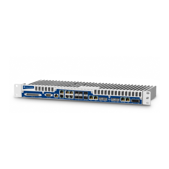
PTP 820F is a compact unit that fits in a single rack unit, with a passive cooling system that eliminates the need for fans. A PTP 820F system consists of a PTP 820F indoor unit (IDU) and up to three radio frequency units (RFUs). The IDU is connected to each RFU by a standard Cat-5e or preferably Cat-6/6e cable, with RF-45 connectors on the RFU and electrical or optical fiber via SFP on the IDU. -
Page 18: Ethernet Management Interfaces
Figure 2 GbE Combo Interface Numbering Note When using electrical ports GbE 1 through GbE 4 to connect between the PTP 820F IDU and an outdoor unit such as PTP 820C or PTP 820S, in areas in which severe lightning conditions are likely to occur, it is required to use lightning protection. -
Page 19: Management Interface Cable Options
PTP 820G Ethernet split cable for Management E1/DS1 Interface PTP 820F includes an MDR69 connector in which 16 E1 interfaces are available (ports 1 through 16). STM-1/OC-3 Interfaces The PTP 820F includes two ch-STM-1/OC-3 ports, which can be used as a 1+1 STM-1/OC-3 protection configuration. -
Page 20: Power Interfaces
SM-card aluminum cover. In the event of IDU replacement, re-using the existing SM card cover is necessary to ensure that the unit’s software and configuration is maintained. An SM card is pre-installed inside each PTP 820F unit. It can also be ordered as a separate item (e.g., as a spare unit). -
Page 21: Figure 5 Sm Card And Cover
Figure 5 SM Card and Cover 2-10 phn-4750_003v006... -
Page 22: Chapter 3 Preparing For Installation
Chapter 3 Preparing for Installation This section provides instructions for transporting, inspecting, and unpacking the equipment for an PTP 820F system prior to installation. Transportation/Storage The equipment cases are prepared for shipment by air, truck, railway and sea, suitable for handling by forklift trucks and slings. - Page 23 Changes or modifications not expressly approved by Cambium Networks could void the user's authority to operate the equipment Where special cables, shields, adapters and grounding kits are supplied or described in this manual, these items must be used, to comply with the relevant regulations.
-
Page 24: Chapter 4 Installing The Ptp 820F Idu
Installing the PTP 820F IDU in the Rack (19") Insert and hold the PTP 820F IDU in the rack, as shown in the following figures. Use four screws (not supplied with the installation kit) to fasten the IDU to the rack. -
Page 25: Grounding The Ptp 820F
If you are installing multiple PTP 820F units in a single rack, make sure to leave a space of 1RU after every two PTP 820F units, as shown in the figure below. This restriction also applies to PTP 820F units installed in proximity with third party units. -
Page 26: Replacing An Ptp 820F Idu Or Sm-Card
Replacing an PTP 820F IDU or SM-Card If you should need to replace the PTP 820F IDU, you must first remove the SM-Card Cover so that you can insert it into the new IDU. The SM-Card holds the configuration and software for the IDU. The SM-Card is embedded in the SM- Card plastic cover that is located under the SM-card aluminum cover. - Page 27 In the new IDU or, if you are upgrading the SM-Card, the old IDU, make sure that there is no foreign matter blocking the sockets in the opening where the SM-Card is installed. Gently place the SM-Card in its place and tighten the 2 screws. Place the SM-Card’s aluminum cover in its place and tighten the 2 screws.
-
Page 28: Chapter 5 Connecting The Power Cable
Chapter 5 Connecting the Power Cable Note Before connecting the power supply to the PTP 820F unit, you must verify that the positive pole in the external power supply is grounded! Power supply grounding should be in according with the following figure. -
Page 29: Figure 8 Correct Wiring Of Power Connector
Insert the wires into the connector. Secure the wires in the connector with the screws. Plug the connector into the PTP 820F power interface and tighten the two screws on the sides of the connector to secure the connector. Figure 9 Connecting the Power Cable... -
Page 30: Chapter 6 Power Supply Notes
Chapter 6 Power Supply Notes When selecting a power source, the following must be considered: • Voltage range: -40 VDC to -60 VDC. • Recommended: Availability of a UPS (Uninterrupted Power Source), battery backup, and emergency power generator. • The power source must be grounded. •... -
Page 31: Chapter 7 Idu-Rfu Cable Connection
Chapter 7 IDU-RFU Cable Connection RFU-D, RFU-D-HP and RFU-S can be connected to the PTP 820F IDU via a standard CAT-5e or preferably CAT-6/6a cable, with RJ-45 connectors on the RFU and an RJ-45 connector on the IDU. They can also be connected to the IDU over optical fiber cables via the optical (SFP) RFU interface on the IDU. -
Page 32: Chapter 8 Performing Initial Configuration
User Guide for PTP 820F, PTP 820G. Establishing a Connection You can connect to the PTP 820F unit using a TP cable with a LAN connection or using a Serial RS- 232 cable. Connecting to the Unit with a Serial Connection Connect an RS-232 cable with an RJ-45 interface from your laptop or PC to the Terminal Interface on the PTP 820F front panel. -
Page 33: Logging On
To establish a connection between the PC and the PTP 820F unit, it is necessary to have an IP address on the PC within the same subnet as the unit. The default IP address of the PTP 820F unit is 192.168.1.1. -
Page 34: Changing Your Password
Changing Your Password It is recommended to change your default Admin password as soon as you have logged into the system. To change your password: Select Platform > Security > Access Control > Change Password. The Change User Password page opens. Figure 13: Change User Password Page In the Old password field, enter the current password. -
Page 35: Configuration
In addition to setting the IP addresses, the following configuration steps should be performed to establish basic connectivity. For a detailed description of these procedures, refer to the User Guide for PTP 820F, and PTP 820G. • Enable the Radio Interfaces •... -
Page 36: Chapter 9 Specifications
Chapter 9 Specifications Environmental Specifications for IDU • Operating: ETSI EN 300 019-1-3 Class 3.2 • Temperature: -5 °C (23 F) to 55 °C (131 F) - Temperature range for continuous operating temperature with high reliability. -25 °C (-13 F) to 65 °C (149 F) - Temperature range for exceptional temperatures, tested successfully, with limited margins. -
Page 37: Power Consumption Specifications
IDU-RFU Connection An RFU-S, RFU-D, and RFU-D-HP can be connected to an PTP 820F IDU via a standard CAT-5e or CAT-6 cable, with RJ-45 connectors on the RFU and one of the RJ-45 RFU interfaces on the PTP 820F. They can also be connected to the IDU over optical fiber cables via one of the optical (SFP) RFU interfaces on the IDU. -
Page 38: Chapter 10 Acceptance And Commissioning Procedures
Chapter 10 Acceptance and Commissioning Procedures This chapter provides Cambium's recommended Acceptance and Commissioning Procedure for PTP 820. Acceptance and commissioning should be performed after initial setup is complete. The purpose of this procedure is to verify correct installation and operation of the installed link and the interoperability with customer end equipment. - Page 39 SITE ACCEPTANCE CHECKLIST Mount is grounded as per site specifications All steelwork is Galvanized or Stainless Steel as appropriate 3. ANTENNA Antenna type (model and size): Antenna is securely fixed to mount Antenna is grounded as per site specifications Antenna sway braces are installed correctly (where applicable) Antenna Radome is securely fitted (where applicable) Water drain plugs are fitted and removed, as appropriate Antenna sealing O-Ring is properly fitted and not damaged...
- Page 40 SITE ACCEPTANCE CHECKLIST Cable connected securely to RFU and IDU Cable connector is weather-proofed (sealed) at the RFU At the RFU, cable has a service/drip loop to prevent moisture from entering the connector Cable is secured using suitable restraints to fixed points at regular intervals (0.5 m recommended) Cable has no sharp bends, kinks, or crushed areas.
- Page 41 SITE ACCEPTANCE CHECKLIST Traffic cables and connections are properly terminated as per manufacturer/cable instructions All cabling is secured, tidy, and visibly labeled 8. DC POWER SUPPLY - Two Inputs Measured DC voltage input to the IDU: (-40.5 to -60 VDC) Power-Supply maximum current: (at least 3 Ampere per carrier)
-
Page 42: Site Acceptance Checklist Notes
SITE ACCEPTANCE CHECKLIST Date: Site Acceptance Checklist Notes The following notes provide important additional information about the Site Acceptance Checklist. Antenna Mounting • Mounting pole is of sufficient height to clear local obstructions, such as parapets, window cleaning gantries, and lift housings. •... -
Page 43: Radio Link Commissioning Procedure
• All labeling is complete as per site requirements. Labeling is specific to each customer. At a site with only one installation, labeling may be unnecessary. However, at sites with multiple installations, correct and adequate labeling is essential for future maintenance operations. -
Page 44: Ptp 820 Commissioning Log
The Commissioning Log gathers all relevant information regarding the installed link and contains a checklist of all recommended commissioning tests. Maintaining the Commissioning Log is important for tracking your installations, and to provide essential data for Cambium Networks. Upon completing the Commissioning Log, send the log to Cambium support center at support@cambiumnetworks.com. - Page 45 PTP 820 LINK COMMISSIONING LOG ATPC on/off: ATPC ref level: RFU Polarization: 3. ANTENNA AND RFU MOUNT Site 1 Site 2 Antenna vendor and model: Antenna size: Mounting type: Mounting losses: 4. LINK PARAMETERS Site 1 Site 2 Link distance: Rain zone: Expected RSL (dBm): Expected Diversity RSL (dBm):...
- Page 46 PTP 820 LINK COMMISSIONING LOG Default router: In-band VLAN 7. REMARKS/NOTES 8. INSTALLATION INFORMATION Name: Company: Installed by: Date: Signature: Name: Company: Commissioned by: Date: Signature: 10-35 phn-4750_003v006...
Need help?
Do you have a question about the PTP 820F and is the answer not in the manual?
Questions and answers