Table of Contents
Advertisement
Quick Links
Advertisement
Table of Contents

Related Manuals for Cambium Networks PTP 850E


Summary of Contents for Cambium Networks PTP 850E
- Page 1 Installation Guide PTP 850E System Release 10.9...
- Page 2 While reasonable efforts have been made to assure the accuracy of this document, Cambium Networks assumes no liability resulting from any inaccuracies or omissions in this document, or from use of the information obtained herein. Cambium reserves the right to...
-
Page 3: Table Of Contents
Transportation and Storage ......................12 Unpacking .............................. 13 Inspection ............................... 13 Torque Requirements ........................13 Product Hardware Description ......................14 PTP 850E Hardware Overview ......................14 PTP 850E Interfaces ..........................15 PoE Injector ..............................16 PoE Injector Interfaces ........................17 System Components ..........................17 Adaptors and Installation Kits ...................... - Page 4 Pole Mount Assembly and Installation ..................64 Wall Mount Assembly and Installation ..................66 Procedure .............................. 67 Attaching the PTP 850E to the Installation and Alignment Device ......68 Performing Antenna Alignment Using the Enhanced Alignment Kit ......69 Adjusting the Antenna Azimuth ....................69 Adjusting the Antenna Elevation ....................
- Page 5 Multiband Configurations ....................90 Multiband with PTP 850E and PTP 820C with 2+0 Single Polarization...... 90 Multiband with PTP 850E and PTP 820C with 2+0 Dual Polarization ......93 Multiband with PTP 850E and 1+0 PTP 820S ................95 Page 5 of 99...
- Page 6 List of Figures Figure 1: PTP 850E Rear View (Left) and Front View (Right) ..............14 Figure 2: Cable Gland Construction ......................14 Figure 3: PTP 850E Interfaces – ESE ....................... 15 Figure 4: PoE Injector ..........................16 Figure 5: PoE Injector Ports ........................17 Figure 6: PTP 850E ..........................
- Page 7 List of Tables Table 1: PTP 850E Accessories ....................... 17 Table 2: PoE Injector ..........................18 Table 3: QSFP Accessories ................. Error! Bookmark not defined. Table 4: Cable Grounding Kit ........................21 Table 5: Ethernet Cable Color Code ....................... 27 Table 6: Outdoor Ethernet Cable Electrical Requirements ..............
-
Page 8: Before You Start
• PTP 850E is intended for installation in a restricted access location. • PTP 850E must be installed and permanently connected to protective earth by qualified service personnel in accordance with applicable national electrical codes. • Before starting an installation, use a leveler to make sure that the poles are 100% vertical. -
Page 9: Hardware Warranty
Hardware warranty Cambium’s standard hardware warranty is for one (1) year from date of shipment from Cambium Networks or a Cambium distributor. Cambium Networks warrants that hardware will conform to the relevant published specifications and will be free from material defects in material and workmanship under normal use and service. -
Page 10: Cautions
Note text. Caring for the environment The following information describes national or regional requirements for the disposal of Cambium Networks supplied equipment and for the approved disposal of surplus packaging. In EU countries The following information is provided to enable regulatory compliance with the European Union (EU) directives identified and any amendments made to these directives when using Cambium equipment in EU countries. -
Page 11: In Non-Eu Countries
To avoid malfunctioning or personnel injuries, equipment or accessories/kits/plug-in unit installation, requires qualified and trained personnel. Changes or modifications not expressly approved by Cambium Networks could void the user's authority to operate the equipment. Where special cables, shields, adapters and grounding kits are supplied or described in this manual, these items must be used, to comply with the FCC regulations. -
Page 12: Précautions Générales Relatives À L'équipement
skal det ved tilkopling av utstyret til kabel-TV nettet installeres en galvanisk isolator mellom utstyret og kabel- TV nettet. Utrustning som är kopplad till skyddsjord via jordat vägguttag och/eller via annan utrustning och samtidigt är kopplad till kabel-TV nät kan i vissa fall medfőra risk főr brand. -
Page 13: Unpacking
M8 screws: 20 Nm • M3 screws (used with PTP 820C and PTP 820S twist): 0.6 Nm • #4-40 Screws (used with PTP 850E and PTP 850E coupler/splitter twist): 0.8 Nm • Page 13 of 99... -
Page 14: Product Hardware Description
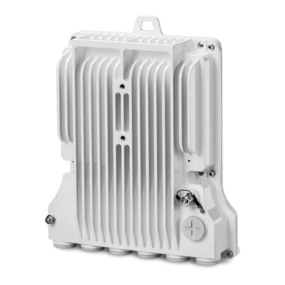
Product Hardware Description PTP 850E Hardware Overview PTP 850E features an all-outdoor architecture consisting of a single unit, which can be either directly mounted on the antenna or supplied with an integrated antenna. Note The equipment is type approved and labeled according to Radio Equipment Directive –... -
Page 15: Ptp 850E Interfaces
RJ-45 port for management and PoE. For power, the PTP 850E has a DC power interface (-48V) (Port 1). The PTP 850E can also receive PoE power from a Cambium approved PoE injector via Port 2, an RJ-45 port that is also used for management. -
Page 16: Poe Injector
Note Not all ports are supported in the initial PTP 850E release. For information on supported ports, check the Release Notes for the Release version you are using. Antenna Port –proprietary flange (flange compliant with UG385/U) • RSL interface – DVM interface to enable voltage measurement for RSL indication. The •... -
Page 17: Poe Injector Interfaces
DC Power Port 2 -(18-60) V • Grounding screw Figure 5: PoE Injector Ports System Components The following figures show the main components used in the PTP 850E installation procedures. Figure 6: PTP 850E Figure 7: OMT Adaptors and Installation Kits... -
Page 18: Antenna Connection
N800082L002A PTP 820E Splitter Kit N800082L003A PTP 820E Coupler Kit N800082L004A PTP 820E Flat Antenna Mounting kit Table 2: PoE Injector Part number Description N000082L164A PTP 820C INDOOR AC POE INJECTOR, 90W PTP 820 PoE Injector all outdoor, N000082L022A redundant DC input, +24VDC support N000082L020A PTP 820 PoE Injector 19inch rack mount KIT N000082L021A... -
Page 19: Power Consumption Specifications
Power Consumption Specifications Unit Configuration Maximum Power Consumption Active Standby Power Connection Options Power Source and Range Data Connection Connection DC Cable Type / Type Length Gage Ext DC Optical ≤ 75m (247ft) 18AWG -(40.5 ÷ 60)VDC 76m ÷ 150m 14AWG (Using an RJ-45 to DC cable adaptor) (248ft ÷... -
Page 20: Environmental Specifications
The maximum rating of the overcurrent protection shall be up to 6 Amp. • Environmental Specifications Operating: ETSI EN 300 019-1-4 Class 4.1 Temperature range for continuous operating temperature with high reliability: -33°C (-27°F) to +55°C (131°F) Temperature range for exceptional temperatures; tested successfully, with limited margins: -45°C (-49°F) to +60°C (140°F) Humidity: 5%RH to 100%RH IEC529 IP66... -
Page 21: Cable Installation And Grounding
Minimum and Maximum Cable Diameter To fit the gland, the outer cable diameter should be between 6-10 mm. This applies to all glands on both the PTP 850E unit and the PoE Injector. Grounding the Cables Cables must be grounded as follows: For fiber cables (see Connecting an Optical Fiber Cable and SFP), no grounding is •... - Page 22 To connect the grounding kit: Strip the cable jacket. Place the cable in the middle of the grounding bracket. Close the grounding bracket around the cable. Page 22 of 99...
- Page 23 Tighten the two screws to secure the grounding bracket around the cable. Install the grounding lug on the grounding bar. Tighten the grounding lug. Page 23 of 99...
-
Page 24: Grounding The Ptp 850E Unit
Metric wrench 10mm Procedure On the front of each PTP 850E unit, loosen the nut, plain washer, and serrated washer from the GND stud, using the metric offset hexagon key and the wrench. Place the cable lug (supplied with the PTP 850E grounding kit) in place on the screw. -
Page 25: Power Source
The user power supply GND must be connected to the positive pole in the PTP 850E power supply. Any other connection may cause damage to the system! Note For the warranty to be honored, you must install the PTP 850E in accordance with the instructions above. Surge Protection PTP 850E includes built-in surge protection for its Ethernet and power interfaces. -
Page 26: Available Cable Options
Available Cable Options Note For 10G connections longer than 80m, only Single Mode cables can be used. Fiber Optic Cables – Single Mode Part number Item Description N000082L139A PTP 850 Optical CABLE,SM, 30m N000082L140A PTP 850 Optical CABLE,SM, 50m N000082L141A PTP 850 Optical CABLE,SM, 80m N000082L142A PTP 850 Optical CABLE,SM, 100m... -
Page 27: Outdoor Ethernet Cable Specifications
Figure 9: Cable Design • [1]Conductor • [2]Insulation • [3]Screen: Alu/Pet foil. Alu outside • [4]Tinned copper braid • [5]Jacket Table 4: Ethernet Cable Color Code Pair Wire A Wire B WHITE-blue BLUE WHITE-orange ORANGE WHITE-green GREEN WHITE-brown BROWN Outdoor Ethernet Cable Specifications Table 5: Outdoor Ethernet Cable Electrical Requirements Cable type CAT-5e SFUTP, 4 pairs, according to... -
Page 28: Outdoor Dc Cable Specifications
Pinout Table 6: Outdoor Ethernet Cable Mechanical/Environmental Requirements Jacket UV resistant 6-10 mm Outer diameter Operating and Storage -40°C - 85°C temperature range Flammability rating According to UL-1581 VW1, IEC 60332-1 RoHS According to Directive/2002/95/EC Outdoor DC Cable Specifications Table 7: Outdoor DC Cable Electrical Requirements Cable type 2 tinned copper wires Wire gage... -
Page 29: Securing The Cables
This is especially important for optical (SFP) cables. Special Instructions for use of Glands Note Each PTP 850E unit is supplied with two glands. If additional glands are required, they must be ordered separately, in kits of five glands each. Table 9: Glands Kit... -
Page 30: General Installation Procedure
This procedure applies to all cable types and explains how to install the cables using long glands. The gland is supplied assembled. When using the power adaptor (see section 2.2, PTP 850E Interfaces), perform these steps to prepare the cable: Strip off a maximum of 20 mm from the cable jacket. - Page 31 For all installations, perform the following steps: Before inserting a cable, you must disassemble the gland cap and gland rubber from the gland body. Slide the gland cap into the cable. Slide the gland rubber into the cable. Page 31 of 99...
- Page 32 Slide the cable into the body of the gland. If you are using a gland cap (see Step 5), make sure to leave enough space for the gland cap to fit into the gland without disturbing the cable. Optionally, after securing the cable into the body of the gland, you can close the other side of the gland with an M28 gland cap.
- Page 33 The M28 gland cap has hook on top. After attaching the gland cap to the gland, you can connect a rope to the hook and use this to lift the gland and cable up to the radio unit. Before screwing the gland into the radio unit, you must remove the gland cap. Page 33 of 99...
- Page 34 If you used an M28 gland cap to close the gland when raising the gland and cable to the radio unit, remove the gland cap from the gland at this point by unscrewing the cap. Connect the cable to the port. Screw the gland into the radio unit until there is full contact between the gland and the radio unit.
-
Page 35: Figure 10: Tightening The Front Portion Of The Gland
11. Tighten the rear portion of the gland onto the main part of the gland and make sure that the main part of the gland does not have an additional swivel after the rear portion is secured. Note If the main portion of the gland is rotated while the rear portion is seizing the cable, this may ruin the cable connector. -
Page 36: Connecting An Optical Fiber Cable And Sfp
Connecting an Optical Fiber Cable and SFP Types of SFPs The PTP 850E includes a QSFP cage (P4) that supports four 1/10 GbE interfaces. These interfaces correspond to logical ports 3, 4, 5, and 6. P4 can also be used with an adaptor to support a single SFP+ module (1/10 GbE). The following table provides the marketing model of the adaptor. -
Page 37: Connecting Optical Fiber To Sfps
The following table lists recommended SFP modules that can be used with PTP 850E. Table 12: SFP Module Recommendations Part number Item Description N000082L059A PTP 820 SFP Optical 1000Base-LX,EXT TEMP N000082L072A PTP 820 SFP Optical 1000Base-SX,EXT TEMP N000082L117A PTP 820 SFP Electric Int 1000Base-T,EXT TEMP The following table lists recommended CSFP modules that can be used with PTP 850E. - Page 38 Slide the gland cap into the cable. Slide the rubber into the cable. Insert the fibers together with the connectors into the cable gland. Secure the cable to the lip of the gland using a tie wrap. Note If you are raising the cable to a radio unit on a tower, this step is crucial to prevent the cable from slipping from the gland, which could damage the connector.
- Page 39 Remove the tie wrap securing the cable to the gland. Note A new tie wrap must be used to secure the cable to the gland at the end of the procedure, as described in Step 13. 10. Connect the connector into the PTP 850E connector. Page 39 of 99...
- Page 40 11. Tighten the gland to the radio unit until there is full contact between the gland and the radio unit. 12. Tighten the gland cap. Note Before tightening the gland, make sure the gland is aligned with the tapped hole in the unit.
- Page 41 Secure the cable to the gland using a tie wrap. Page 41 of 99...
-
Page 42: Connecting A Dc Power Cable
Connecting a DC Power Cable Note The DC power cable and connector must be ordered separately. See DC Cable Connector. To connect a DC power cable: Strip off 45 mm from the cable jacket. Expose 10 mm at the edge of each of the two wires. Insert the power cable into the gland. - Page 43 Plug the power cable with connector into the PTP 850E power connector. Tighten the two front screws. Screw the gland into the radio unit. Note Before tightening the gland, make sure the gland is even with the cover. Tighten the gland gently and make sure there is no resistance. If there is resistance, stop immediately and verify that the gland is not being inserted at an angle.
- Page 44 the gland at an angle can ruin the thread on the gland and prevent proper sealing of the interface. 10. Tighten the gland cap. 11. Secure the cable to the gland with a tie wrap. Page 44 of 99...
-
Page 45: Connecting The Ethernet Cable
If you need to assemble the Ethernet cable, follow the instructions in Preparing the Ethernet Cable and Plug-in Field, then proceed to Connection of Ethernet Cable to PTP 850E. If you using a pre-assembled Ethernet cable, follow the instructions in Preparing the Ethernet Cable Already Assembled, then proceed to Connection of Ethernet Cable to PTP 850E. - Page 46 Do not strip off the end of the cable shield, but rather, twist the shield to form a braid. Roll back the foil shield insulation and wrap the drain wire around the foil. Do not remove any insulation from the conductors. Align the colored wires.
- Page 47 10. Wrap the twisted braid firmly around the cable jacket and let the crimping tail of the RJ45 plug envelop it. Note To ensure proper grounding, it is essential that the twisted braid be firmly connected to the RJ45 plug. 11.
-
Page 48: Preparing The Ethernet Cable Already Assembled
Connection of Ethernet Cable to PTP 850E To connect the Ethernet cable to the PTP 850E: Remove the relevant cap from the PTP 850E radio. You can use the side of the gland to unscrew the cap. Page 48 of 99... - Page 49 Connect the CAT5E cable to the PTP 850E. Screw the gland into the radio unit. Note Before tightening the gland, make sure the gland is even with the cover. Tighten the gland gently and make sure there is no resistance. If there is resistance, stop immediately and verify that the gland is not being inserted at an angle.
- Page 50 Tighten the gland cap. Secure the cable to the gland using a tie wrap. Page 50 of 99...
-
Page 51: Connection Of Extension Cable To Ptp 850E
Release version you are using. To connect the Protection cable to the PTP 850E: Remove the relevant cap from the PTP 850E radio. You can use the side of the gland to unscrew the cap Connect the CAT5e cable to the PTP 850E. - Page 52 Tighten the gland cap. 5. Secure the cable to the gland with a tie wrap 6. Connect the other side of the cable to the other PTP 850E following steps 1-5. Page 52 of 99...
-
Page 53: Poe Injector Installation And Connection
The total length of the cable between the PTP 850E port and the Switch/Router the device is connected to should not exceed 100m/328ft. This length includes the connection between the PTP 850E and the PoE Injector (X1 + X2 ≤ 100m/328ft in the figure below). -
Page 54: Poe Injector Grounding
Note For the warranty to be honored, the connection must be through the glands only. Do not open the PoE injector box cover. PoE Injector Grounding To ground the PoE Injector: On the right side of each PoE Injector, loosen the screw, plain washer, and serrated washer. - Page 55 Procedure Mount and tighten the PoE Injector to a wall using two M6 bolts and anchors. The M6 bolts and anchors must be purchased separately. Note Use Anchor Stainless Steel with flanged Hexagonal nut M6X70. Drill two 6mm diameter holes with 100mm distance between the center of the holes. Insert the anchors with the bolts.
-
Page 56: Poe Injector Pole Mount Installation
PoE Injector Pole Mount Installation List of Items Item Description Quantit Remarks PoE Injector Required Tools • Slot Screwdriver Procedure To mount the PoE Injector on a pole: Mount and tighten the PoE Injector to a pole with a diameter of 114 mm using a stainless-steel hose clamp. -
Page 57: Poe Injector 19" Rack Installation
Note The Hose Clamp is not supplied with PoE injector kit. Attach the PoE injector to the pole. Connect the ends of the hose clamp. Tighten the hose clamp using the captive screw. PoE Injector 19” Rack Installation List of Items Item Description Quantit... -
Page 58: Poe Injector Etsi Rack Installation
Mount the 19” rack adaptor to a 19” rack using four M6 screws and cage nuts. PoE Injector ETSI Rack Installation List of Items Item Description Quantit Remarks PoE Injector Page 58 of 99... - Page 59 Item Description Quantit Remarks PoE Injector ETSI Rack Mount Kit Required Tools • Philips Screwdriver To mount the PoE Injector to an ETSI rack: Mount the PoE Injector to an ETSI rack using a 19” rack adaptor and ETSI adapting ears. Connect the ETSI adapting ears to a 19”...
- Page 60 Note For this type of installation, a 2RU space is required. Page 60 of 99...
-
Page 61: Installation Procedure And Antenna Alignment - 1+0 With 43 Dbi Flat Antenna And Alignment Device
Alignment – 1+0 with 43 dBi Flat Antenna and Alignment Device When you order an PTP 850E with a 43 dBi flat antenna, the radio and antenna are delivered together as a single unit. The polarization is determined by the placement of the radio- antenna unit. -
Page 62: Figure 13 Installation And Alignment Device - Azimuth Range (Pole Mount)
You can adjust the elevation from the delivery position of 22° downward up to a position as far as 45° upward. Be sure to attach the PTP 850E radio and antenna to the installation and alignment device before adjusting the elevation, otherwise the weight of the radio and antenna might accidently reduce the elevation angle. -
Page 63: Figure 14 Installation And Alignment Device - Delivery Elevation (22° Downward)
Figure 14 Installation and Alignment Device – Delivery Elevation (22° Downward) You can adjust the elevation upwards as far as 45° upward. Figure 15 Installation and Alignment Device – Highest Elevation (45° Upward) Page 63 of 99... -
Page 64: Pole Mount Assembly And Installation
Note The PTP 850E radio can be assembled on the installation and alignment device on the ground, prior to attaching the device to the pole mount, if the logistics of the location make this more feasible than attaching the radio afterwards. See Attaching the PTP 850E to the Installation and Alignment Device. - Page 65 2. To secure the installation and alignment device to the pole, tighten the four nuts on the outer bracket, two on each side as shown in the figure below. Page 65 of 99...
-
Page 66: Wall Mount Assembly And Installation
15 Item Description Quantity Remarks PTP 850E Flat Antenna Mounting Kit PTP 850E radio with 43 dBi Flat Antenna Anchor screws M8x70 Not supplied with mounting kit M8x45 screws... -
Page 67: Procedure
Procedure 1. Place the mounting kit on the wall and mark four screws positions. 2. Remove the bracket and drill four holes into the wall. 3. Insert the anchor screws into the wall. 4. Place the mounting kit in front of the 4 anchor screws and tighten the 4 M8 screws, spring washers, and flat washers to secure the mounting device to the wall. -
Page 68: Attaching The Ptp 850E To The Installation And Alignment Device
Attaching the PTP 850E to the Installation and Alignment Device 1. Connect the PTP 850E unit to the installation and alignment device, using the two M8 screws and washers supplied with the installation and alignment kit. Attach the PTP 850E according to the desired polarization, as shown in the figures below. Note that: For horizontal polarization, the upper screw must be approximately 10:00 to the left, •... -
Page 69: Performing Antenna Alignment Using The Enhanced Alignment Kit
Performing Antenna Alignment Using the Enhanced Alignment Kit You can easily adjust the azimuth and elevation of the antenna using a number of screws and nuts located on the installation and alignment device (Figure 28). Adjusting the Antenna Azimuth Note For wall-mount installations, if it is necessary to adjust the azimuth by more than 45°, you must first adjust the position of the Azimuth Screws. - Page 70 Manually adjust the azimuth base to its required location. Page 70 of 99...
- Page 71 Once the azimuth base has been adjusted to its approximate location, lock the azimuth fixing pin by rotating the pin clockwise until it appears to be aligned with its groove. At this point, you must adjust the azimuth base until the fixing pin slips into its groove.
-
Page 72: Adjusting The Antenna Elevation
Performing Fine Azimuth Adjustment To perform fine azimuth alignment: Turn the Azimuth Nut (Figure 28), either by hand or using a key wrench, for fine tuning of the azimuth. Each ¼ turn is equal to an adjustment of 0.25°. Tighten the two M8 Azimuth Screws connected to the azimuth base. Adjusting the Antenna Elevation Performing Gross Elevation Adjustment To perform gross adjustment of the antenna elevation:... - Page 73 Move the Elevation Adaptor to the required location. Page 73 of 99...
- Page 74 Once the Elevation Adaptor has been adjusted to its approximate location, lock the elevation fixing pin by rotating the pin clockwise until it appears to be aligned with its groove. At this point, you must adjust the Elevation Adaptor until the fixing pin slips into its groove.
- Page 75 Performing Fine Elevation Adjustment To perform fine elevation alignment: Turn the Elevation Nut (Figure 28), either by hand or using a key wrench, for fine tuning of the elevation. Each ¼ turn is equal to an adjustment of 0.25°. Tighten the two M8 Elevation Screws connected to the Elevation Adaptor. Page 75 of 99...
-
Page 76: Direct Mount Configurations
• Metric offset hexagon key wrench #6 • Phillips #2 screwdriver Procedure To install the PTP 850E in a direct mount 1+0 configuration: Note Do not remove the transparent pressure window located on the antenna interface. Antenna Interface Page 76 of 99... - Page 77 Note If necessary, change the antenna polarization by rotating the unit in accordance with the relevant antenna installation guide. Twist orientation: • For horizontal polarization, locate the twist with the letter “H” vertical to the hook cover (at 3:00) and fasten the two screws. Page 77 of 99...
- Page 78 For vertical polarization, locate the twist with the letter “V” vertical to the hook cover (at 3:00) and fasten the two screws. Mount the PTP 850E on the antenna using the four M8 captive screws and washers that are supplied, assembled, in the PTP 850E, and tighten the screws.
-
Page 79: 1+1 Hsb And 2+0 Single Polarization
Note Make sure the polarization mounting direction of the PTP 850E is correct. 1+1 HSB and 2+0 Single Polarization List of Items Item Description Quantity Remarks PTP 850E Radio For 1+1 HSB, use a Coupler PTP 820E-CPLR-Kit PTP 820E- For 2+0 Single Polarization, use a Splitter. -
Page 80: Figure 20: Horizontal Polarization
Procedure To install an PTP 850E in a direct mount 1+1 or 2+0 SP configuration: 1 If necessary, change the polarization of the coupler or splitter to the desired polarization by loosening the twist, changing the polarization as indicated below, and re-tightening the screws. -
Page 81: Figure 21: Vertical Polarization
Figure 21: Vertical Polarization 2 Mount the coupler or splitter on the antenna using the four M8 screws and washers supplied with the coupler or splitter kit, and tighten the screws. 3 Mount the two O-Rings supplied with the coupler or splitter kit, as shown in the following figure. - Page 82 4 Mount the PTP 850E to the body of the coupler or splitter using the four M8 captive screws and washers that are supplied, assembled, with the PTP 850E, and tighten the screws. 5 Repeat Step 4 for the second PTP 850E.
-
Page 83: 2+0 Direct Mount Dual Polarization
2+0 Direct Mount Dual Polarization List of Items Item Description Quantity Remarks PTP 850E Radio PTP 820E-OMT-Kit Required Tools The following tools are required for the installation: Metric offset hexagon key wrench #6 • Phillips #2 screwdriver • Metric offset hexagon key wrench #2.5 and #3 •... -
Page 84: 2+0 Single Polarization
3 Change the polarization of one of the PTP 850E radios to ‘H’ polarization. See 1+0 Direct Mount Installation. 4 Mount an PTP 850E radio to each side of the OMT. When mounting the radios, make sure that one side is polarized ‘V’ and the other side is polarized ‘H’. - Page 85 Metric offset hexagon key wrench #2.5 and #3 Procedure To install a PTP 850E in a direct mount 1+1 or 2+0 SP configuration: Mount the twist to the coupler or splitter using the O-Ring and four screws supplied in the Twist kit and tighten the screws.
-
Page 86: Figure 38: Horizontal Polarization
Figure 22: Horizontal Polarization Figure 23: Vertical Polarization Mount the coupler or splitter on the antenna using the four M8 screws and washers supplied with the coupler or splitter kit and tighten the screws. Mount the two O-Rings supplied with the coupler or splitter kit, as shown in the following figure. - Page 87 Mount the PTP 850E to the body of the coupler or splitter using the four M8 captive screws and washers that are supplied, assembled, with the PTP 850E, and tighten the screws. Page 87 of 99...
-
Page 88: 2+0 Dual Polarization
2+0 Dual Polarization List of Items Description Quantity Remarks PTP 850E Radio PTP 850E OMT Kit Required Tools The following tools are required for the installation: • Metric offset hexagon key wrench #6 • Phillips #2 screwdriver • Metric offset hexagon key wrench #2.5 and #3... - Page 89 Change the polarization of one of the PTP 850E radios to ‘H’ polarization. Mount a PTP 850E radio to each side of the OMT. When mounting the radios, make sure that one side is polarized ‘V’ and the other side is polarized ‘H’. Tighten the radios to the OMT kit using the four M8 captive screws and washers that are supplied, assembled, with the PTP 850E radio.
-
Page 90: Multiband Configurations
For configurations with PTP 850E and PTP 820C or PTP 820S, a special Multiband antenna can be used. This antenna transmits and receives both E-band and microwave signals. Both units (PTP 850E and PTP 820C or PTP 820S) are connected to this antenna via direct mount. Table 15: Multiband Antenna Part number... - Page 91 Procedure 1. Assemble the antenna according to the instructions provided with the antenna. 2. Install the PTP 850E directly to the back of the antenna, as shown in the figure below. Use the procedure described in 1+0 Direct Mount Installation.
- Page 92 4. Mount and tighten the PTP 820C Splitter Kit at a 90° angle to the antenna using the four M8 screws and washers. 5. Mount and tighten the PTP 820C to the PTP 820C Splitter Kit using the four M8 captive screws and washers supplied with the PTP 820C radio.
-
Page 93: Multiband With Ptp 850E And Ptp 820C With 2+0 Dual Polarization
Assemble the antenna according to the instructions provided with the antenna. Install the PTP 850E directly to the back of the antenna, as shown in the figure below. Use the procedure described in 1+0 Direct Mount Installation. Page 93 of 99... - Page 94 Connect the OMT at a 90° angle to the antenna and secure it with the four screws supplied with the OMT kit. Verify the existence of the O-ring. Connect the PTP 820C unit to the OMT using the four M8 captive screws and washers supplied with the PTP 820C and tighten the screws.
-
Page 95: Multiband With Ptp 850E And 1+0 Ptp 820S
Assemble the antenna according to the instructions provided with the antenna. Install the PTP 850E directly to the back of the antenna, as shown in the figure below. Use the procedure described in 1+0 Direct Mount Installation. Page 95 of 99... - Page 96 Mount the PTP 820S on the antenna using the four M8 captive screws and washers that are supplied, assembled, with the PTP 820S, and tighten the screws. Note Make sure the polarization mounting direction of the PTP 820S is correct. Page 96 of 99...
- Page 97 Important! Make sure the polarization mounting direction of the PTP 820S is correct. Important! Do not remove the transparent pressure window located on the antenna interface. If necessary, change the antenna polarization by rotating the unit in accordance with the relevant antenna installation guide. If necessary, change the polarization of the radios by adjusting the twist.
-
Page 98: Figure 40: Ptp 820Stwist Orientation
Figure 24: PTP 820STwist Orientation • For horizontal polarization, locate the twist with the letter “H” vertical to the hook cover and fasten the two screws. Page 98 of 99... - Page 99 • For vertical polarization, locate the twist with the letter “V” vertical to the hook cover and fasten the two screws. Page 99 of 99...
Need help?
Do you have a question about the PTP 850E and is the answer not in the manual?
Questions and answers