Table of Contents
Advertisement
Quick Links
Advertisement
Table of Contents

Related Manuals for Cambium Networks PTP 820E


Summary of Contents for Cambium Networks PTP 820E
- Page 2 Accuracy While reasonable efforts have been made to assure the accuracy of this document, Cambium Networks assumes no liability resulting from any inaccuracies or omissions in this document, or from use of the information obtained herein. Cambium reserves the right to make changes to any products described herein to improve reliability, function, or design, and reserves the right to revise this document and to make changes from time to time in content hereof with no obligation to notify any person of revisions or changes.
-
Page 3: Table Of Contents
Product Hardware Description ......................14 PTP 820E Hardware Overview ....................... 14 PTP 820E Interfaces ..........................15 PTP 820E Interfaces – ESE ........................16 PTP 820E Interfaces – ESP ........................17 Common PTP 820E Interfaces ....................... 18 PoE Injector ............................19 PoE Injector Interfaces .......................... - Page 4 Preparing the Ethernet Cable and Plug-in Field ..................48 Preparing the Ethernet Cable Already Assembled ................51 Connection of Ethernet Cable to PTP 820E ................... 51 Connection of Extension Cable to PTP 820E ..................54 PoE Injector Installation and Connection ............... 56 PoE Injector Cable Connection ......................
- Page 5 2+0 Dual Polarization ..........................99 Multiband Configurations ................... 101 Multiband with PTP 820E and PTP 820C with 2+0 Single Polarization ..........101 Multiband with PTP 820E and PTP 820C with 2+0 Dual Polarization ..........105 Multiband with PTP 820E and 1+0 PTP 820S ..................107...
-
Page 6: List Of Figures
Figure 18: Tightening the Rear Portion of the Gland .............. 37 Figure 19: Mount Pole Mount to Pole ..................67 Figure 20: PTP 820E Radio with 43 dBi Flat Antenna –Polarization Labels ......68 Figure 21: V+45° Polarization ....................69 Figure 22: V-45°... - Page 7 Figure 33: Horizontal Polarization – Screws Location ............. 82 Figure 34: Vertical Polarization – Radio and Installation and Alignment Kit ......83 Figure 35: Vertical Polarization – Screws Location ..............83 Figure 36: Azimuth Screws – Top View (Azimuth 45° to the Right) ........87 Figure 37: Removing the Azimuth Screws (Side View) ............
-
Page 8: List Of Tables
List of Tables Table 1: PTP 820E Port distribution per hardware Model ..................15 Table 2: PTP 820E Chassis Marketing Models......................15 Table 3: PTP 820E Accessories ..........................21 Table 4: PoE Injector ..............................21 Table 5: Two-Wire to PoE Port Power Adaptor ....................... 22 Table 6: Cable Grounding Kit ........................... -
Page 9: Before You Start
• PTP 820E is intended for installation in a restricted access location. PTP 820E must be installed and permanently connected to protective earth by qualified service personnel in • accordance with applicable national electrical codes. -
Page 10: Repair And Service
Hardware warranty Cambium’s standard hardware warranty is for one (1) year from date of shipment from Cambium Networks or a Cambium distributor. Cambium Networks warrants that hardware will conform to the relevant published specifications and will be free from material defects in material and workmanship under normal use and service. -
Page 11: Warnings
Note Note text. Caring for the environment The following information describes national or regional requirements for the disposal of Cambium Networks supplied equipment and for the approved disposal of surplus packaging. In EU countries The following information is provided to enable regulatory compliance with the European Union (EU) directives identified and any amendments made to these directives when using Cambium equipment in EU countries. -
Page 12: In Non-Eu Countries
Disposal of Cambium equipment European Union (EU) Directive 2002/96/EC Waste Electrical and Electronic Equipment (WEEE) Do not dispose of Cambium equipment in landfill sites. For disposal instructions, refer to http://www.cambiumnetworks.com/support. Disposal of surplus packaging Do not dispose of surplus packaging in landfill sites. In the EU, it is the individual recipient’s responsibility to ensure that packaging materials are collected and recycled according to the requirements of EU environmental law. -
Page 13: Inspection
Inspection Check the packing lists and ensure that correct parts numbers quantities of goods have arrived. Inspect for any damage on the cases and equipment. Report any damage or discrepancy to a Cambium representative, by e-mail or fax. Page 13 of 110... -
Page 14: Product Hardware Description
Product Hardware Description PTP 820E Hardware Overview PTP 820E features an all-outdoor architecture consisting of a single unit, which can be either directly mounted on the antenna or supplied with an integrated antenna. Note The equipment is type approved and labelled according to the EU’s Radio Equipment Directive 2014/53/EU. -
Page 15: Ptp 820E Interfaces
The Extension port is smaller than the other ports and requires a special gland. PTP 820E Interfaces There are two basic PTP 820E hardware versions with the following interface layouts: • ESE – Two electrical Ethernet interfaces (Port 1 and Port 3) and one optical SFP cage that supports regular and CSFP standards (Port 2). -
Page 16: Ptp 820E Interfaces - Ese
PTP 820E Interfaces – ESE Figure 3: PTP 820E Interfaces – ESE Port 1 (Eth1): • Electric: 10/100/1000Base-T RJ-45. • Port 2 SFP cage which supports – Regular and CSFP standards Regular SFP provides Eth2 CSFP (Dual BiDir SFP) provides Eth2 and Eth3 •... -
Page 17: Ptp 820E Interfaces - Esp
PTP 820E Interfaces – ESP Figure 4: PTP 820E Interfaces – ESP Port 1 (MGT): • Electric: 10/100/1000Base-T RJ-45. Management port (no traffic) • Port 2 SFP cage which supports – Regular and CSFP standards Regular SFP provides Eth2 CSFP (Dual BiDir SFP) provides Eth2 and Eth3 Port 3 (Eth1): •... -
Page 18: Common Ptp 820E Interfaces
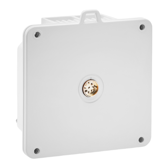
XPIC and HSB are planned for future release. • Antenna Port – Cambium proprietary flange (flange compliant with UG385/U) RSL interface – PTP 820E uses a two-pin connection to measure the RSL level using standard voltmeter • test leads: Figure 5: RSL Interface Note The RSL interface includes a docking slot for a WiFi module plugin module. -
Page 19: Poe Injector
• Grounding screw Figure 6: Grounding Screw PoE Injector The PoE injector is an outdoor unit which can be mounted on a wall, pole, or indoor rack. Each PoE Injector kit includes the following items: • PoE injector • 2 DC power connectors Figure 7: PoE Injector Following PoE Injector is available: N000082L022A... -
Page 20: Poe Injector Interfaces
PoE Injector Interfaces • Power-Over-Ethernet (PoE) Port GbE Data Port supporting 10/100/1000Base-T • • DC Power Port 1 -(18-60) V or -(40-60) V • DC Power Port 2 -(18-60) V Grounding screw • Figure 8: PoE Injector Ports Powering with External DC For configurations in which power is not provided via PoE, a special adaptor (PTP 820 Mini Power Adaptor) is available that enables users to connect a two-wire power connector to the PoE port. -
Page 21: System Components
System Components The following figures show the main components used in the PTP 820E installation procedures. Figure 10: PTP 820E Figure 11: Coupler/Splitter Figure 12: OMT Figure 13: PoE Injector Figure 14: Twist for Coupler/Splitter Adaptors and Installation Kits Table 3: PTP 820E Accessories... -
Page 22: Antenna Connection
PTP 820 Mini Power Adaptor Antenna Connection Direct Mount: CommScope (VHLP) Note Appropriate lubricant or grease can be applied to the screws that connect the PTP 820E to the antenna interface. Power Specifications Power Input Specifications Standard Input -48 VDC nominal DC Input range -40.5 to -60 VDC... -
Page 23: Power Connection Options
Power Connection Options Power Source and Range Data Connection Type Connection Length DC Cable Type / Gage Ext DC Optical ≤ 150m 18AWG -(40.5 ÷ 60) VDC (Using an RJ-45 to DC cable adaptor) Optical 150m ÷ 300m 14AWG PoE Injector Electrical ≤... -
Page 24: Cable Installation And Grounding
Cable Installation and Grounding Minimum and Maximum Cable Diameter To fit the gland, the outer cable diameter should be between 6-10 mm. This applies to all glands on both the PTP 820E unit and the PoE Injector. To fit the grounding clamp, the outer diameter of CAT5E Ethernet cables must be between 6-7.1mm. Grounding the Cables Cables must be grounded as follows: For fiber cables (see Connecting an Optical Fiber Cable and SFP on page 38), no grounding is required. - Page 25 To connect the grounding kit: Strip the cable jacket. Place the cable in the middle of the grounding bracket. Close the grounding bracket around the cable. Page 25 of 110...
- Page 26 Tighten the two screws to secure the grounding bracket around the cable. Install the grounding lug on the grounding bar. Tighten the grounding lug. Page 26 of 110...
-
Page 27: Grounding The Ptp 820E Unit
• Procedure On the front of each PTP 820E unit, loosen the nut, plain washer, and serrated washer from the GND stud, using the metric offset hexagon key and the wrench. Place the cable lug (supplied with the PTP 820E grounding kit) in place on the screw. -
Page 28: Power Source
The power supply must have grounding points on the AC and DC sides. Caution The user power supply GND must be connected to the positive pole in the PTP 820E power supply. Any other connection may cause damage to the system! -
Page 29: Available Cable Options
Available Cable Options Fiber Optic Cables – Single Mode Part number Item Description N000082L139A PTP 820 Optical CABLE,SM, 30m N000082L140A PTP 820 Optical CABLE,SM, 50m N000082L141A PTP 820 Optical CABLE,SM, 80m N000082L142A PTP 820 Optical CABLE,SM, 100m N000082L143A PTP 820 Optical CABLE,SM, 150m DC Cable and Connector Marketing P/N Description... -
Page 30: Outdoor Ethernet Cable Specifications
Figure 16: Cable Design [1]Conductor • • [2]Insulation • [3]Screen: Alu/Pet foil. Alu outside [4]Tinned copper braid • • [5]Jacket Table 7: Ethernet Cable Color Code Pair Wire A Wire B WHITE-blue BLUE WHITE-orange ORANGE WHITE-green GREEN WHITE-brown BROWN Outdoor Ethernet Cable Specifications Table 8: Outdoor Ethernet Cable Electrical Requirements CAT-5e SFUTP, 4 pairs, according to ANSI/TIA/EIA-568-B-2 Cable type... -
Page 31: Outdoor Dc Cable Specifications
Pinout Table 9: Outdoor Ethernet Cable Mechanical/Environmental Requirements Jacket UV resistant Outer diameter 6-7.1 mm (in order to be compatible with the grounding clamp, CAT5E_gnd_kit) Operating and Storage -40°C - 85°C temperature range Flammability rating According to UL-1581 VW1, IEC 60332-1 RoHS According to Directive/2002/95/EC Outdoor DC Cable Specifications... -
Page 32: Securing The Cables
(SFP) cables. Special Instructions for use of Glands Note Each PTP 820E unit is supplied with two glands. If additional glands are required, they must be ordered separately, in kits of five glands each. Table 12: Glands Kit... -
Page 33: General Installation Procedure
This procedure applies to all cable types and explains how to install the cables using long glands. The gland is supplied assembled. When using the power adaptor (see section 2.2, PTP 820E Interfaces), perform these steps to prepare the cable: Strip off a maximum of 20 mm from the cable jacket. - Page 34 For all installations, perform the following steps: Before inserting a cable, you must disassemble the gland cap and gland rubber from the gland body. Slide the gland cap into the cable. Slide the gland rubber into the cable. Slide the cable into the body of the gland. If you are using a gland cap (see Step 5), make sure to leave enough space for the gland cap to fit into the gland without disturbing the cable.
- Page 35 Optionally, after securing the cable into the body of the gland, you can close the other side of the gland with an M28 gland cap. The gland cap protects the cable and connector from damage when elevating the cable and gland to the radio unit. The M28 gland cap has hook on top.
- Page 36 If you used an M28 gland cap to close the gland when raising the gland and cable to the radio unit, remove the gland cap from the gland at this point by unscrewing the cap. Connect the cable to the port. Screw the gland into the radio unit until there is full contact between the gland and the radio unit.
-
Page 37: Figure 17: Tightening The Front Portion Of The Gland
11. Tighten the rear portion of the gland onto the main part of the gland and make sure that the main part of the gland does not have an additional swivel after the rear portion is secured. Note If the main portion of the gland is rotated while the rear portion is seizing the cable, this may ruin the cable connector. -
Page 38: Connecting An Optical Fiber Cable And Sfp
CSFP ports, with opposite wavelengths for TX and RX. The following table provides an example of a valid CSFP- SFP pair in which TX=1310nm and RX=1490nm for the CSFP connected to the PTP 820E, and TX=1490nm and RX=1310nm for the SFP connected to the third party equipment. -
Page 39: Table 16: Sfp Module Recommendations
The following table lists recommended SFP modules that can be used with PTP 820E. Table 15: SFP Module Recommendations Part number Item Description N000082L072A PTP 820 SFP Optical 1000Base-SX,EXT TEMP N000082L059A PTP 820 SFP Optical 1000Base-LX,EXT TEMP N000082L117A PTP 820 SFP Electric Int 1000Base-T,EXT TEMP The following table lists recommended CSFP modules that can be used with PTP 820E. -
Page 40: Connecting Optical Fiber To Sfps
Connecting Optical Fiber to SFPs To connect an optical fiber cable and the SFP transceiver: Use a pre-assembled cable. Split the connector into two separate LC connectors (one for each fiber). Remove the gland cap and rubber from the gland body. Slide the gland cap into the cable. - Page 41 Secure the cable to the lip of the gland using a tie wrap. Note If you are raising the cable to a radio unit on a tower, this step is crucial to prevent the cable from slipping from the gland, which could damage the connector. Connect the fibers to the SFP transceiver.
- Page 42 Remove the tie wrap securing the cable to the gland. Note A new tie wrap must be used to secure the cable to the gland at the end of the procedure, as described in Step 13. 10. Connect the connector into the PTP 820E connector. Page 42 of 110...
- Page 43 11. Tighten the gland to the radio unit until there is full contact between the gland and the radio unit. 12. Tighten the gland cap. Note Before tightening the gland, make sure the gland is aligned with the tapped hole in the unit. Tightening the gland at an angle can ruin the thread on the gland and prevent proper sealing of the interface.
- Page 44 Secure the cable to the gland using a tie wrap. Page 44 of 110...
-
Page 45: Connecting A Dc Power Cable
Connecting a DC Power Cable Note The DC power cable and connector must be ordered separately. See DC Cable and Connector on page To connect a DC power cable: Strip off 45 mm from the cable jacket. Expose 10 mm at the edge of each of the two wires. Insert the power cable into the gland. - Page 46 Plug the power cable with connector into the PTP 820E power connector. Screw the gland into the radio unit. Note Before tightening the gland, make sure the gland is even with the cover. Tighten the gland gently and make sure there is no resistance. If there is resistance, stop immediately and verify that the gland is not being inserted at an angle.
- Page 47 Tighten the gland cap. Secure the cable to the gland with a tie wrap. Page 47 of 110...
-
Page 48: Connecting The Ethernet Cable
If you need to assemble the Ethernet cable, follow the instructions in section 3.11.1, Preparing the Ethernet Cable and Plug-in Field, then proceed to section 3.11.3, Connection of Ethernet Cable to PTP 820E. If you using a pre-assembled Ethernet cable, follow the instructions in section 3.11.2, Preparing the Ethernet Cable Already Assembled, then proceed to section 3.11.3, Connection of Ethernet Cable to PTP 820E. - Page 49 Do not strip off the end of the cable shield, but rather, twist the shield to form a braid. Roll back the foil shield insulation and wrap the drain wire around the foil. Do not remove any insulation from the conductors. Align the colored wires.
- Page 50 10. Wrap the twisted braid firmly around the cable jacket and let the crimping tail of the RJ45 plug envelop it. Note To ensure proper grounding, it is essential that the twisted braid be firmly connected to the RJ45 plug. 11.
-
Page 51: Preparing The Ethernet Cable Already Assembled
Connection of Ethernet Cable to PTP 820E To connect the Ethernet cable to the PTP 820E: Remove the relevant cap from the PTP 820E radio. You can use the side of the gland to unscrew the cap. Page 51 of 110... - Page 52 Connect the CAT5E cable to the PTP 820E. Screw the gland into the radio unit. Note Before tightening the gland, make sure the gland is even with the cover. Tighten the gland gently and make sure there is no resistance. If there is resistance, stop immediately and verify that the gland is not being inserted at an angle.
- Page 53 Tighten the gland cap. Secure the cable to the gland using a tie wrap. Page 53 of 110...
-
Page 54: Connection Of Extension Cable To Ptp 820E
Connection of Extension Cable to PTP 820E This cable is supplied with the glands attached. It is used to connect two PTP 820E radios in XPIC and HSB configurations. To connect the Extension cable to the PTP 820E: Remove the hexagon cap from the PTP 820E radio. You can use a flat screwdriver or a wrench to open the cap. - Page 55 Tighten the gland cap. Connect the other side of the cable to the other PTP 820E following steps 1-4. Page 55 of 110...
-
Page 56: Poe Injector Installation And Connection
PoE Injector. • The total length of the cable between the PTP 820E port and the Switch/Router the device is connected to should not exceed 100m/328ft. This length includes the connection between the PTP 820E and the PoE Injector (X1 + X2 ≤... -
Page 57: Poe Injector Grounding
PoE Injector Grounding To ground the PoE Injector: On the right side of each PoE Injector, loosen the screw, plain washer, and serrated washer. Place the cable lug (supplied with the PoE injector kit) between the plain and serrated washer. Tighten the screw. - Page 58 Note Use Anchor Stainless Steel with flanged Hexagonal nut M6X70. Drill two 6mm diameter holes with 100mm distance between the center of the holes. Insert the anchors with the bolts. Place the washers on the bolt. Tighten the nuts. Page 58 of 110...
-
Page 59: Poe Injector Pole Mount Installation
PoE Injector Pole Mount Installation List of Items Item Description Quantity Remarks PoE Injector Required Tools • Slot Screwdriver Procedure To mount the PoE Injector on a pole: Mount and tighten the PoE Injector to a pole with a diameter of 114 mm using a stainless-steel hose clamp. -
Page 60: Poe Injector 19" Rack Installation
Attach the PoE injector to the pole. Connect the ends of the hose clamp. Tighten the hose clamp using the captive screw. PoE Injector 19” Rack Installation List of Items Item Description Quantity Remarks PoE Injector PoE Injector 19” Rack Mount Kit Required Tools Philips Screwdriver •... -
Page 61: Poe Injector Etsi Rack Installation
Mount the 19” rack adaptor to a 19” rack using four M6 screws and cage nuts. PoE Injector ETSI Rack Installation List of Items Item Description Quantity Remarks PoE Injector PoE Injector ETSI Rack Mount Kit Page 61 of 110... - Page 62 Required Tools • Philips Screwdriver To mount the PoE Injector to an ETSI rack: Mount the PoE Injector to an ETSI rack using a 19” rack adaptor and ETSI adapting ears. Connect the ETSI adapting ears to a 19” rack adaptor using four M6 screws. Mount the PoE Injector on the adaptor through the wall mounting holes using M6 screws and washers.
- Page 63 Note For this type of installation, a 2RU space is required. Page 63 of 110...
-
Page 64: Installation Procedure And Antenna Alignment - 1+0 With 43 Dbi Flat Antenna And Standard Alignment Device (Class 2 Antennas)
The pole diameter range for pole mount installations is 8.89 cm – 11.43 cm (3.5 inches – 4.5 inches). List of Items Item Description Quantity Remarks PTP 820E Mounting kit for the PTP 820E Required Tools • Torque wrench with socket key wrench inch set Torque wrench with socket key wrench metric set •... - Page 65 Connect the azimuth and elevation adjusters with two sets of M10x30 bolts, nuts, spring washers, and flat washers. Do not tighten the bolts at this point in the installation. Insert two M10x130 bolts on the azimuth adjuster. Remove the nuts, spring washers, flat washers, and square cushion block from the azimuth adjuster bolt. Page 65 of 110...
- Page 66 Insert the azimuth adjuster bolt onto the azimuth adjuster. Rotate the azimuth adjuster to connect the azimuth adjuster bolt with the elevation adjuster with an M10x55 bolt, spring washers, and flat washers, and install the nuts, washers, and square cushion block removed in Step 4 on the azimuth adjuster bolt.
-
Page 67: Figure 19: Mount Pole Mount To Pole
Tighten all the bolts, as shown in the following figure. Mount and tighten the pole mount to a pole with a diameter of 114 mm using the two washers and screws supplied with the PTP 820E integrated antenna pole mount kit. Figure 19: Mount Pole Mount to Pole... -
Page 68: Radio And Antenna Installation
Procedure When you order a PTP 820E with a 43 dBi flat antenna, the radio and antenna are delivered together as a single unit. The polarization is determined by the placement of the radio-antenna unit. To comply with Class 2 RPE pattern, the unit must be installed in a diamond-shaped position, so that the vertical polarization is either 45°... -
Page 69: Figure 21: V+45° Polarization
For example, if the unit at the local site is installed with a V+45° polarization, the unit at the remote site must be installed with a V-45° polarization, and vice versa. To install a PTP 820E with a 43 dBi flat antenna: Attach the L-bracket provided with the PTP 820E to the pole mount. Page 69 of 110... -
Page 70: Figure 23: V+45° Polarization (A On Top)
Attach the radio to the L-bracket according to the correct polarization, with the pole behind the radio, and tighten the two captive screws. The installation angle depends on whether you are installing the radio with a V+45° polarization, a V-45° polarization, or vertical polarization. The following figures show the various polarization options. -
Page 71: Figure 24: V-45° Polarization (B On Top)
Figure 24: V-45° Polarization (B on Top) Figure 25: Vertical Polarization Page 71 of 110... -
Page 72: Performing Antenna Alignment Using The Standard Alignment Kit
When looking at a complete link the radios should be aligned in the same direction. This means the radios face each other in a mirror image, as shown in the following figure. Figure 26: Complete Link – V-45° Polarization at Local Site (Left), V+45° Polarization at Remote Site (Right) Performing Antenna Alignment Using the Standard Alignment Kit You can perform adjustments to the azimuth and elevation of the antenna by turning bolts on the pole mount. -
Page 73: Adjusting The Antenna's Azimuth
Adjusting the Antenna’s Azimuth Large-Scale Azimuth Adjustment To perform large-scale azimuth adjustment: Loosen the two nuts ( in the figure above) on the clamp ( in the figure above) on the pole mount. Push the pole mount softly, by hand. The pole mount is adjustable 360° around the pole. Fine Azimuth Adjustment To perform fine azimuth adjustment: Loosen the top and bottom fixed bolts on the azimuth axis (... - Page 74 Loosen the top and bottom bolts that connect the pole mount to the antenna adaptor ( . in the figure below). Rotate the elevation adjusting bolt ( in the figure below) to adjust the antenna’s elevation within ±15°. Tighten the top and bottom bolts connecting the pole mount to the antenna adaptor. The recommended torque for these bolts is 25 Nm.
-
Page 75: Installation Procedure And Antenna Alignment - 1+0 With 43 Dbi Flat Antenna And Enhanced Alignment Device (Class 3 Antennas)
1+0 with 43 dBi Flat Antenna and Enhanced Alignment Device (Class 3 Antennas) When you order a PTP 820E with a 43 dBi flat antenna, the radio and antenna are delivered together as a single unit. The polarization is determined by the placement of the radio-antenna unit. -
Page 76: Figure 28: Installation And Alignment Device - Azimuth Range
Upon delivery, the installation and alignment device is aligned 45° downward (elevation) and straight ahead (azimuth). You can adjust the azimuth up to 45° in either direction by manually turning the azimuth base. Figure 28: Installation and Alignment Device – Azimuth Range Page 76 of 110... -
Page 77: Figure 29: Installation And Alignment Device - Extended Azimuth Range
You can adjust the elevation from the delivery position of 45° downward to a position as far as 45° upward. Be sure to attach the PTP 820E radio and antenna to the installation and alignment device before adjusting the elevation, otherwise the weight of the radio and antenna might accidently reduce the elevation angle. -
Page 78: Pole Mount Assembly And Installation
The pole diameter range for pole mount installations is 8.89 cm – 11.43 cm (3.5 inches – 4.5 inches). Note The PTP 820E radio can be assembled on the installation and alignment device on the ground, prior to attaching the device to the pole mount, if the logistics of the location make this more feasible than attaching the radio afterwards. -
Page 79: Procedure
Required Tools • Socket key wrench inch set Socket key wrench metric set • • Open metric wrench set Procedure Open the outer bracket to slide the installation and alignment device onto the pole, then close the bracket as shown in the figure below. Page 79 of 110... -
Page 80: Wall Mount Assembly And Installation
15 kg. Item Description Quantity Remarks PTP 820E Flat Antenna Mounting Kit PTP 820E radio with 43 dBi Flat Antenna Anchor screws M8x70 Not supplied with mounting kit M8x45 screws Not supplied with mounting kit M8 spring washer... -
Page 81: Procedure
Required Tools • Appropriate key wrench for the M8x45 screws A drilling machine • Note In wall mount assembly, the 4 M10 nuts, 2 M10 flat and spring washers, 2 M10x150 screws, and the rear bracket that are supplied with the mounting kit are not used. Procedure Place the mounting kit on the wall and mark four screws positions. -
Page 82: Attaching The Ptp 820E To The Installation And Alignment Device
Attaching the PTP 820E to the Installation and Alignment Device Connect the PTP 820E unit to the installation and alignment device, using the two M8 screws and washers supplied with the installation and alignment kit. Attach the PTP 820E according to the desired polarization, as shown in the figures below. -
Page 83: Performing Antenna Alignment Using The Enhanced Alignment Kit
Figure 34: Vertical Polarization – Radio and Installation and Alignment Kit Figure 35: Vertical Polarization – Screws Location Performing Antenna Alignment Using the Enhanced Alignment Kit You can easily adjust the azimuth and elevation of the antenna using a number of screws and nuts located on the installation and alignment device (Figure 28). - Page 84 Performing Gross Azimuth Adjustment To adjust the antenna azimuth: Loosen the Azimuth Fixing Pin (Figure 28) by pulling it gently out of its groove and rotating it counter- clockwise. Manually adjust the azimuth base to its required location. Page 84 of 110...
- Page 85 Once the azimuth base has been adjusted to its approximate location, lock the azimuth fixing pin by rotating the pin clockwise until it appears to be aligned with its groove. At this point, you must adjust the azimuth base until the fixing pin slips into its groove. There are notches within the device that enable you to adjust the azimuth in 15°...
- Page 86 Performing Fine Azimuth Adjustment To perform fine azimuth alignment: Turn the Azimuth Nut (Figure 28), either by hand or using a key wrench, for fine tuning of the azimuth. Each ¼ turn is equal to an adjustment of 0.25°. Tighten the two M8 Azimuth Screws connected to the azimuth base. Page 86 of 110...
-
Page 87: Figure 36: Azimuth Screws - Top View (Azimuth 45° To The Right)
Extending the Azimuth Range To extend the azimuth range beyond 45° in either direction: Manually rotate the azimuth base 45° in the direction you want to align the azimuth. Remove the two Azimuth Screws. Figure 36: Azimuth Screws – Top View (Azimuth 45° to the Right) Figure 37: Removing the Azimuth Screws (Side View) Page 87 of 110... -
Page 88: Figure 38: Azimuth Screws In New Placement - Top View (Azimuth 45° To The Right)
Insert the Azimuth Screws in the holes opposite their previous locations. For example, if you are adjusting the azimuth to the left, move the Azimuth Screw to the left of the device from the left hole to the right hole and move the Azimuth Screw to the right of the device from the right hole to the left hole, as shown in Figure 37 and Figure 39. -
Page 89: Adjusting The Antenna Elevation
Figure 39: Repositioning the Azimuth Screws (Side View) Tighten the two Azimuth Screws by hand, leaving them free enough so that you can manually rotate the azimuth base. Follow the procedures in Performing Gross Azimuth Adjustment and Performing Fine Azimuth Adjustment to further adjust the azimuth from the 45°... - Page 90 Once the Elevation Adaptor has been adjusted to its approximate location, lock the elevation fixing pin by rotating the pin clockwise until it appears to be aligned with its groove. At this point, you must adjust the Elevation Adaptor until the fixing pin slips into its groove. There are notches within the device that enable you to adjust the elevation in 15°...
- Page 91 Performing Fine Elevation Adjustment To perform fine elevation alignment: Turn the Elevation Nut (Figure 28), either by hand or using a key wrench, for fine tuning of the elevation. Each ¼ turn is equal to an adjustment of 0.25°. Tighten the two M8 Elevation Screws connected to the Elevation Adaptor. Page 91 of 110...
-
Page 92: Direct Mount Configurations
• Metric offset hexagon key wrench #6 Phillips #2 screwdriver • Procedure To install the PTP 820E in a direct mount 1+0 configuration: Note Do not remove the transparent pressure window located on the antenna interface. Page 92 of 110... -
Page 93: Figure 40: Horizontal / Vertical Pole
Note If necessary, change the antenna polarization by rotating the unit in accordance with the relevant antenna installation guide. Figure 40: Horizontal / Vertical Pole Page 93 of 110... - Page 94 Twist orientation: • For horizontal polarization, locate the twist with the letter “H” vertical to the hook cover (at 3:00) and fasten the two screws. Page 94 of 110...
- Page 95 For vertical polarization, locate the twist with the letter “V” vertical to the hook cover (at 3:00) and fasten the two screws. Mount the PTP 820E on the antenna using the four M8 captive screws and washers that are supplied, assembled, in the PTP 820E, and tighten the screws.
-
Page 96: 2+0 Single Polarization
Metric offset hexagon key wrench #2.5 and #3 Procedure To install a PTP 820E in a direct mount 1+1 or 2+0 SP configuration: Mount the twist to the coupler or splitter using the O-Ring and four screws supplied in the Twist kit and tighten the screws. -
Page 97: Figure 41: Horizontal Polarization
Figure 41: Horizontal Polarization Figure 42: Vertical Polarization Mount the coupler or splitter on the antenna using the four M8 screws and washers supplied with the coupler or splitter kit and tighten the screws. Mount the two O-Rings supplied with the coupler or splitter kit, as shown in the following figure. Page 97 of 110... - Page 98 Mount the PTP 820E to the body of the coupler or splitter using the four M8 captive screws and washers that are supplied, assembled, with the PTP 820E, and tighten the screws. Page 98 of 110...
-
Page 99: 2+0 Dual Polarization
2+0 Dual Polarization List of Items Item Description Quantity Remarks PTP 820E Radio PTP 820E OMT Kit Required Tools The following tools are required for the installation: • Metric offset hexagon key wrench #6 Phillips #2 screwdriver • • Metric offset hexagon key wrench #2.5 and #3... - Page 100 Change the polarization of one of the PTP 820E radios to ‘H’ polarization. Mount a PTP 820E radio to each side of the OMT. When mounting the radios, make sure that one side is polarized ‘V’ and the other side is polarized ‘H’. Tighten the radios to the OMT kit using the four M8 captive screws and washers that are supplied, assembled, with the PTP 820E radio.
-
Page 101: Multiband Configurations
PTP 820E can be used in Multiband configurations with PTP 820C, PTP 820S, or third-party microwave radios. For configurations with PTP 820E and PTP 820C or PTP 820S, a special Multiband antenna can be used. This antenna transmits and receives both E-band and microwave signals. Both units (PTP 820E and PTP 820C or PTP 820S) are connected to this antenna via direct mount. - Page 102 Procedure Adjust the twist on both the PTP 820E antenna interface and the PTP 820C Splitter. Perform one of the following steps, according to the required polarization (horizontal or vertical). For horizontal polarization, locate the holes above and below the letter “H” on the pins and fasten the two screws.
- Page 103 Assemble the antenna according to the instructions provided with the antenna. Install the PTP 820E directly to the back of the antenna, as shown in the figure below. Use the procedure described in 1+0 Direct Mount Installation on page 92.
- Page 104 Mount and tighten the PTP 820C Splitter Kit at a 90° angle to the antenna using the four M8 screws and washers. Mount and tighten the PTP 820C to the PTP 820C Splitter using the four M8 captive screws and washers supplied with the PTP 820C.
-
Page 105: Multiband With Ptp 820E And Ptp 820C With 2+0 Dual Polarization
Assemble the antenna according to the instructions provided with the antenna. Install the PTP 820E directly to the back of the antenna, as shown in the figure below. Use the procedure described in 1+0 Direct Mount Installation on page 92. - Page 106 820E 820C Connect the OMT at a 90° angle to the antenna and secure it with the four screws supplied with the OMT kit. Verify the existence of the O-ring. Connect the PTP 820C unit to the OMT using the four M8 captive screws and washers supplied with the PTP 820C and tighten the screws.
-
Page 107: Multiband With Ptp 820E And 1+0 Ptp 820S
Assemble the antenna according to the instructions provided with the antenna. Install the PTP 820E directly to the back of the antenna, as shown in the figure below. Use the procedure described in 1+0 Direct Mount Installation on page 92. - Page 108 820E PTP 820S Mount the PTP 820S on the antenna using the four M8 captive screws and washers that are supplied, assembled, with the PTP 820S, and tighten the screws. Note Do not remove the transparent pressure window located on the antenna interface. If necessary, change the antenna polarization by rotating the unit in accordance with the relevant antenna installation guide.
-
Page 109: Figure 43: Ptp 820Stwist Orientation
If necessary, change the polarization of the radios by adjusting the twist. For the PTP 50E, see 1+0 Direct Mount Installation on page 92. For the PTP 820S, see the illustration below. Note When tightening the M3 screws on the twist of the PTP 820S, use torque of 0.6 Nm. Figure 43: PTP 820STwist Orientation •... - Page 110 • For vertical polarization, locate the twist with the letter “V” vertical to the hook cover and fasten the two screws. Page 110 of 110...
Need help?
Do you have a question about the PTP 820E and is the answer not in the manual?
Questions and answers