Cambium Networks PTP 820S Technical Description
Hide thumbs
Also See for PTP 820S:
- Installation manual (110 pages) ,
- User manual (672 pages) ,
- Quick start manual (23 pages)
Table of Contents
Advertisement
Quick Links
Advertisement
Table of Contents

Related Manuals for Cambium Networks PTP 820S


Summary of Contents for Cambium Networks PTP 820S
- Page 1 Cambium PTP 820S Technical Description System Release 7.9...
- Page 2 (“High Risk Use”). Any High Risk is unauthorized, is made at your own risk and you shall be responsible for any and all losses, damage or claims arising out of any High Risk Use. © 2014 Cambium Networks Limited. All Rights Reserved. phn-3973 001v000...
-
Page 3: Table Of Contents
In EU countries ..........................6 In non-EU countries ........................6 Chapter 1: Introduction ........................1-1 Product Overview ..........................1-2 Unique PTP 820S Feature Set ......................1-3 System Configurations ........................1-4 Chapter 2: PTP 820S Hardware Description .................. 2-1 PTP 820S Unit Description ........................ 2-2 Hardware Architecture ........................ - Page 4 ATPC ............................4-14 Radio Utilization PMs ........................ 4-15 Ethernet Features ..........................4-16 Ethernet Services Overview ..................... 4-16 PTP 820S’s Ethernet Capabilities ..................... 4-30 Supported Standards ........................ 4-31 Ethernet Service Model ......................4-31 Ethernet Interfaces ........................4-49 Quality of Service (QoS) ......................4-58 Global Switch Configuration ....................
- Page 5 Cable Specifications ........................7-46 Glossary ..............................I List of Figures Figure 1 PTP 820S Rear View (Left) and Front View (Right) ..............2-2 Figure 2 Cable Gland Construction ......................2-2 Figure 3 PTP 820S Block Diagram ......................2-3 Figure 4 PTP 820S Interfaces ........................2-4 Figure 5 Protection Signalling Cable Pinouts ..................
- Page 6 Figure 36 Mobile Backhaul Reference Model ..................4-29 Figure 37 Packet Service Core Building Blocks .................. 4-29 Figure 38 PTP 820S Services Model ....................4-32 Figure 39 PTP 820S Services Core ....................... 4-33 Figure 40 PTP 820S Services Flow ....................... 4-34 Figure 41 Point-to-Point Service ......................
- Page 7 Figure 62 Detailed H-QoS Diagram ..................... 4-75 Figure 63 Scheduling Mechanism for a Single Service Bundle ............4-77 Figure 64 Network Topology with PTP 820S Units and Third-Party Equipment ......4-86 Figure 65 ABN Entity ..........................4-86 Figure 66 G.8032 Ring in Idle (Normal) State ..................4-88 Figure 67 G.8032 Ring in Protecting State ..................
- Page 8 Figure 62 Detailed H-QoS Diagram ..................... 4-75 Figure 63 Scheduling Mechanism for a Single Service Bundle ............4-77 Figure 64 Network Topology with PTP 820S Units and Third-Party Equipment ......4-86 Figure 65 ABN Entity ..........................4-86 Figure 66 G.8032 Ring in Idle (Normal) State ..................4-88 Figure 67 G.8032 Ring in Protecting State ..................
- Page 9 Contents Figure 69 PTP 820S End-to-End Service Management ..............4-92 Figure 70 SOAM Maintenance Entities (Example) ................4-93 Figure 71 EFM Maintenance Entities (Example) ................. 4-94 Figure 72 Transparent Clock Delay Compensation ................4-98 Figure 73 Integrated PTP 820S Management Tools ................5-2 Figure 74 Security Solution Architecture Concept ................
-
Page 10: About This User Guide
About This User Guide This guide describes the PTP 820S installation procedures and provides additional information concerning system parts and frequency bands This guide contains the following chapters: • Chapter 1: Introduction • Chapter 2: PTP 820S Hardware Description •... -
Page 11: Purpose
Problems and warranty Purpose Cambium Networks Point-To-Point (PTP) documents are intended to instruct and assist personnel in the operation, installation and maintenance of the Cambium PTP equipment and ancillary devices. It is recommended that all personnel engaged in such activities be properly trained. -
Page 12: Problems And Warranty
Cambium’s standard hardware warranty is for one (1) year from date of shipment from Cambium Networks or a Cambium distributor. Cambium Networks warrants that hardware will conform to the relevant published specifications and will be free from material defects in material and workmanship under normal use and service. -
Page 13: Security Advice
Security advice Security advice Cambium Networks systems and equipment provide security parameters that can be configured by the operator based on their particular operating environment. Cambium recommends setting and using these parameters following industry recognized security practices. Security aspects to be considered are protecting the confidentiality, integrity, and availability of information and assets. -
Page 14: Warnings, Cautions, And Notes
Warnings, cautions, and notes Warnings, cautions, and notes The following describes how warnings and cautions are used in this document and in all documents of the Cambium Networks document set. Warnings Warnings precede instructions that contain potentially hazardous situations. Warnings are used to alert the reader to possible hazards that could cause loss of life or physical injury. -
Page 15: Caring For The Environment
Caring for the environment The following information describes national or regional requirements for the disposal of Cambium Networks supplied equipment and for the approved disposal of surplus packaging. In EU countries The following information is provided to enable regulatory compliance with the European Union (EU) directives identified and any amendments made to these directives when using Cambium equipment in EU countries. -
Page 16: Chapter 1: Introduction
Chapter 1: Introduction Cambium’s PTP 820S represents a new generation of radio technology, capable of high bit rates and longer reach, and suitable for diverse deployment scenarios. PTP 820S supports cutting edge capacity-boosting techniques, such as QPSK to 2048 QAM and Header De-Duplication, to offer a high capacity solution for every network topology and every site configuration. -
Page 17: Product Overview
Product Overview Product Overview Delivering ultra-high capacity in any licensed band (6-38 GHz) PTP 820S provides a new level of wireless capacity in current and emerging backhaul scenarios. PTP 820S combines a compact, all- outdoor design, QPSK to 2048 QAM modulation, and an advanced feature set for Carrier Ethernet... -
Page 18: Unique Ptp 820S Feature Set
Chapter 1: Introduction Unique PTP 820S Feature Set Unique PTP 820S Feature Set The following table summarizes the basic PTP 820S feature set. Table 1 PTP 820S Feature Set Extended Modulation Range ACM 4-2048 QAM (11 ACM points) Frequency Bands... -
Page 19: System Configurations
Chapter 1: Introduction System Configurations System Configurations PTP 820S is designed to support the following site configurations: • 1+0 Direct Mount • 1+1 HSB Direct Mount • 2+0 Direct Mount Page 1-4... -
Page 20: Chapter 2: Ptp 820S Hardware Description
Chapter 2: PTP 820S Hardware Description This chapter describes the PTP 820S components, interfaces and mediation devices. This chapter includes: • PTP 820S Unit Description • PoE Injector Page 2-1... -
Page 21: Ptp 820S Unit Description
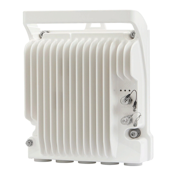
Chapter 2: PTP 820S Hardware Description PTP 820S Unit Description PTP 820S Unit Description PTP 820S features an all-outdoor architecture consisting of a single unit directly mounted on the antenna. Note The equipment is type approved and labelled according to EU Directive 1999/5/EC (R&TTE). -
Page 22: Hardware Architecture
Chapter 2: PTP 820S Hardware Description PTP 820S Unit Description Hardware Architecture The following diagram presents a detailed block diagram of the PTP 820S. Figure 3 PTP 820S Block Diagram The PTP 820S combines full system capabilities with a very compact form-fit. -
Page 23: Interfaces
Chapter 2: PTP 820S Hardware Description PTP 820S Unit Description Interfaces Figure 4 PTP 820S Interfaces • Data Port 1 for GbE traffic: Electric: 10/100/1000Base-T. Supports PoE. Optical: 1000Base-X (optional) • Data Port 2 for GbE traffic: Electric10/100/1000Base-T Optical: 1000Base-X (optional) •... -
Page 24: Management Connection For Protection Configurations
820S units operating in HSB protection mode. The physical cable connection is the same as connecting a CAT5E cable to a system data or management port. Note Other than the pinout connection described above, the cable must be prepared according to the cable preparation procedure described in the PTP 820S Installation Guide. Page 2-5... - Page 25 The splitter has three ports: • System plug (“Sys”) – The system plug must be connected to the PTP 820S’s management port. • Management port (“Mng”) – A standard CAT5E cable must be connected to the splitter’s management port in order to utilize out-of-band (external) management.
-
Page 26: Poe Injector
The PoE injector box is designed to offer a single cable solution for connecting both data and the DC power supply to the PTP 820S system. To do so, the PoE injector combines 48VDC input and GbE signals via a standard CAT5E cable using a proprietary Cambium Networks design. -
Page 27: Figure 7 Poe Injector Ports
Chapter 2: PTP 820S Hardware Description PoE Injector Figure 7 PoE Injector Ports Page 2-8... -
Page 28: Chapter 3: Licensing
This chapter describes PTP 820S’s licensing model. PTP 820S offers a ‘Pay as-you-grow’ licensing concept, in which future capacity growth and additional functionality can be enabled with license keys. For purposes of licensing, each PTP 820S unit is considered a distinct device. Each device contains a single license key. -
Page 29: Working With License Keys
In order to upgrade a license, the license-key must be entered into the PTP 820S. The system checks and implements the new license key, enabling access to new capacities and/or features. -
Page 30: Demo License
Chapter 3: Licensing Demo License Demo License A demo license is available that enables all features for 60 days. The demo license expires 60 days from the time it was activated, and the most recent valid license goes into effect. The 60-day period is only counted when the system is powered up. -
Page 31: Licensed Features
Licenses on page capacity in gradual steps by upgrading your capacity license. Without a capacity license, each PTP 820S unit has a capacity of 10 Mbps. Licensed capacity is available from 100 Mbps to 650 Mbps. N000082L043A Enables the use of Header De-Duplication,... - Page 32 PTP 820S Act.Key - Capacity 500M with ACM Enabled N000082L034A PTP 820S Act.Key - Capacity 650M with ACM Enabled N000082L035A PTP 820S Act.Key - Capacity upgrade from 100 to 500M N000082L036A PTP 820S Act.Key - Capacity upgrade from 100 to 650M Table 4 Edge CET Node Licenses...
-
Page 33: Chapter 4: Feature Description
Chapter 4: Feature Description This chapter describes the main PTP 820S features. The feature descriptions are divided into the categories listed below. This chapter includes: • Innovative Techniques to Boost Capacity and Reduce Latency • External Protection • Synchronization Page 4-1... -
Page 34: Innovative Techniques To Boost Capacity And Reduce Latency
PTP 820S utilizes Cambium’s innovative technology to provide a high-capacity low-latency solution. The total switching capacity of PTP 820S is 5 Gbps or 3.125 Mpps, whichever capacity limit is reached first. PTP 820S also utilizes established technology to provide low latency, representing a 50% latency reduction for Ethernet services compared to the industry benchmark for wireless backhaul. -
Page 35: Capacity Summary
Innovative Techniques to Boost Capacity and Reduce Latency Capacity Summary The total switching capacity of PTP 820S is 5 Gbps or 3.125 Mpps, whichever capacity limit is reached first. A PTP 820S unit can provide the following radio capacity: •... - Page 36 Chapter 4: Feature Description Innovative Techniques to Boost Capacity and Reduce Latency against the number of flows in order to ensure maximum efficiency. Up to 256 concurrent flows are supported. Up to 68 bytes of the L2-4 header can be compressed. Header De-Duplication can be used to compress the following types of header stacks: •...
-
Page 37: Figure 9 Header De-Duplication Operation On Frame Structure
The following figure provides a detailed diagram of how the frame structure is affected by Header De-Duplication. Figure 9 Header De-Duplication Operation on Frame Structure PTP 820S’s Header De-Duplication can improve effective throughput by up to 300% or more without affecting user traffic. Note In a worst-case scenario, Header De-Duplication may add up to 200ns latency. -
Page 38: Frame Cut-Through
Chapter 4: Feature Description Innovative Techniques to Boost Capacity and Reduce Latency Frame Cut-Through Related topics: • Ethernet Latency Specifications • Egress Scheduling Frame Cut-Through is a unique and innovative feature that ensures low latency for delay-sensitive services, such as CES, VoIP, and control protocols. With Frame Cut-Through, high-priority frames are pushed ahead of lower priority frames, even if transmission of the lower priority frames has already begun. -
Page 39: Adaptive Coding Modulation (Acm)
• Quality of Service (QoS) PTP 820S employs full range dynamic ACM. PTP 820S’s ACM mechanism copes with 100 dB per second fading in order to ensure high transmission quality. PTP 820S’s ACM mechanism is designed to work with PTP 820S’s QoS mechanism to ensure that high priority voice and data frames are never dropped, thus maintaining even the most stringent service level agreements (SLAs). -
Page 40: Figure 13 Adaptive Coding And Modulation With 11 Working Points
Chapter 4: Feature Description Innovative Techniques to Boost Capacity and Reduce Latency Eleven Working Points PTP 820S implements ACM with 11 available working points, as shown in the following table: Table 5 ACM Working Points (Profiles) Working Point (Profile) Modulation... - Page 41 ACM and Built-In QoS PTP 820S’s ACM mechanism is designed to work with PTP 820S’s QoS mechanism to ensure that high priority voice and data frames are never dropped, thus maintaining even the most stringent SLAs.
-
Page 42: External Protection
PTP 820S unit belong to a LAG, with 100% distribution to port 1 of the respective PTP 820S unit. If traffic is routed to the PTP 820S units via an external switch, the switch is configured as a static LAG. This is called Line Protection mode. In Line Protection mode, Port 2 on each PTP 820S is connected to Port 2 of the other PTP 820S. -
Page 43: Figure 15 1+1 Hsb Protection - Split Protection Mode
Latency Figure 15 1+1 HSB Protection – Split Protection Mode In a 1+1 HSB configuration, each PTP 820S monitors its own radio. If the active PTP 820S detects a radio failure, it initiates a switchover to the standby PTP 820S. -
Page 44: Figure 17 Internal And Local Management
Chapter 4: Feature Description Innovative Techniques to Boost Capacity and Reduce Latency Figure 17 Internal and Local Management Switchover Triggers In the event of switchover, the standby unit becomes the active unit and the active unit becomes the standby unit. Switchover takes less than 50 msec. The following table lists the switchover triggers for HSB protection according to their priority, with the highest priority triggers listed first. - Page 45 Chapter 4: Feature Description Innovative Techniques to Boost Capacity and Reduce Latency Table 6 HSB Protection Switchover Triggers Priority Fault Notes No mate Caused by the absence of a mate unit or communication cable. Lockout Protection is locked by the user, and switching will not take place under any circumstances.
-
Page 46: Atpc
Chapter 4: Feature Description Innovative Techniques to Boost Capacity and Reduce Latency ATPC ATPC is a closed-loop mechanism by which each carrier changes the transmitted signal power according to the indication received across the link, in order to achieve a desired RSL on the other side of the link. -
Page 47: Radio Utilization Pms
Innovative Techniques to Boost Capacity and Reduce Latency Radio Utilization PMs PTP 820S supports the following counters, as well as additional PMs based on these counters: • Radio Traffic Utilization – Measures the percentage of radio capacity utilization, and used to... -
Page 48: Ethernet Features
PTP 820S features a service-oriented Ethernet switching fabric that provides a total switching capacity of up to 5 Gbps or 3.125 Mpps. PTP 820S has an electrical GbE interface that supports PoE, and two SFP interfaces, as well as an FE interface for management. The second SFP interface can also be used for data sharing. -
Page 49: Figure 18 Basic Ethernet Service Model
Chapter 4: Feature Description Ethernet Features Figure 18 Basic Ethernet Service Model In this illustration, the Ethernet service is conveyed by the Metro Ethernet Network (MEN) provider. Customer Equipment (CE) is connected to the network at the User Network Interface (UNI) using a standard Ethernet interface (10/100 Mbps, 1 Gbps). -
Page 50: Figure 20 Point To Point Evc
Chapter 4: Feature Description Ethernet Features • Connects two or more customer sites (UNIs), enabling the transfer of Ethernet frames between them. • Prevents data transfer involving customer sites that are not part of the same EVC. This feature enables the EVC to maintain a secure and private data channel. A single UNI can support multiple EVCs via the Service Multiplexing attribute. -
Page 51: Figure 22 Rooted Multipoint Evc
Ethernet Features Figure 22 Rooted Multipoint EVC In the PTP 820S, an EVC is defined by either a VLAN or by Layer 1 connectivity (Pipe Mode). Bandwidth Profile The bandwidth profile (BW profile) is a set of traffic parameters that define the maximum limits of the customer’s traffic. -
Page 52: Figure 23 Mef Ethernet Services Definition Framework
If the service frame fails to comply with both the CIR and the EIR defined in the bandwidth profile, it is marked Red and discarded. In the PTP 820S, bandwidth profiles are constructed using a full standardized TrTCM policer mechanism. - Page 53 Chapter 4: Feature Description Ethernet Features Table 7 MEF-Defined Ethernet Service Types Service Type Port Based VLAN-BASED (All to One Bundling) (EVC identified by VLAN ID) E-Line (Point-to- Ethernet Private Line (EPL) Ethernet Virtual Private Line Point EVC) (EVPL) E-LAN Ethernet Private LAN (EP-LAN) Ethernet Virtual Private LAN (Multipoint-to-...
-
Page 54: Figure 24 E-Line Service Type Using Point-To-Point Evc
Chapter 4: Feature Description Ethernet Features Figure 24 E-Line Service Type Using Point-to-Point EVC Ethernet Private Line Service An Ethernet Private Line (EPL) service is specified using an E-Line Service type. An EPL service uses a point-to-point EVC between two UNIs and provides a high degree of transparency for service frames between the UNIs that it interconnects such that the service frame’s header and payload are identical at both the source and destination UNI when the service frame is delivered (L1 service). -
Page 55: Figure 26 Evpl Application Example
Chapter 4: Feature Description Ethernet Features Since service multiplexing is permitted in EVPL services, some service frames may be sent to one EVC while others may be sent to other EVCs. EVPL services can be used to replace Frame Relay and ATM L2 VPN services, in order to deliver higher bandwidth, end-to-end services. -
Page 56: Figure 28 Adding A Site Using An E-Line Service
Chapter 4: Feature Description Ethernet Features used to connect to the Internet, with both services offered via service multiplexing at the same UNI. E-LAN services can simplify the interconnection among a large number of sites, in comparison to hub/mesh topologies implemented using point-to-point networking technologies such as Frame Relay and ATM. -
Page 57: Figure 30 Mef Ethernet Private Lan Example
Chapter 4: Feature Description Ethernet Features Layer 2 service in which each UNI is dedicated to the EP-LAN service. A typical use case for EP- LAN services is Transparent LAN. The following figure shows an example of an EP-LAN service in which the service is defined to provide Customer Edge VLAN (CE-VLAN) tag preservation and tunneling for key Layer 2 control protocols. -
Page 58: Figure 31 Mef Ethernet Virtual Private Lan Example
Chapter 4: Feature Description Ethernet Features Figure 31 MEF Ethernet Virtual Private LAN Example E-Tree Service The E-Tree service type is an Ethernet service type that is based on Rooted-Multipoint EVCs. In its basic form, an E-Tree service can provide a single Root for multiple Leaf UNIs. Each Leaf UNI can exchange data with only the Root UNI. -
Page 59: Figure 33 E-Tree Service Type Using Multiple Roots
Chapter 4: Feature Description Ethernet Features Figure 33 E-Tree Service Type Using Multiple Roots Service multiplexing is optional and may occur on any combination of UNIs in the EVC. For example, an E-Tree service type using a Rooted-Multipoint EVC, and an E-Line service type using a Point-to-Point EVC, can be service multiplexed on the same UNI. -
Page 60: Figure 35 Ethernet Virtual Private Tree Example
Virtual Private Tree service. Figure 35 Ethernet Virtual Private Tree Example PTP 820S enables network connectivity for Mobile Backhaul cellular infrastructure, fixed networks, private networks and enterprises. Mobile Backhaul refers to the network between the Base Station sites and the Network Controller or Gateway sites for all generations of mobile technologies. -
Page 61: Figure 36 Mobile Backhaul Reference Model
Ethernet Features Figure 36 Mobile Backhaul Reference Model The PTP 820S services concept is purpose built to support the standard MEF services for mobile backhaul (MEF 22, mobile backhaul implementation agreement), as an addition to the baseline definition of MEF Services (MEF 6) using service attributes (as well as in MEF 10). E-Line, E-LAN and E-Tree services are well defined as the standard services. -
Page 62: Ptp 820S's Ethernet Capabilities
Carrier-grade service resiliency (G.8032) PTP 820S’s Ethernet Capabilities PTP 820S is built upon a service-based paradigm that provides rich and secure frame backhaul services over any type of transport, with unified, simple and error-free operation. PTP 820S’s services core includes a rich set of tools that includes: •... -
Page 63: Supported Standards
• Enhanced <50msec network level resiliency (G.8032) for ring/mesh support Supported Standards PTP 820S is fully MEF-9 and MEF-14 compliant for all Carrier Ethernet services. For a full list of standards and certifications supported by PTP 820S, see: • Supported Ethernet Standards Ethernet Service Model PTP 820S’s service-oriented Ethernet paradigm is based on Carrier-Ethernet Transport (CET) and... -
Page 64: Figure 38 Ptp 820S Services Model
C-VLAN reuse capabilities of different customers. Users can define up to 64 services on a single PTP 820S. Each service constitutes a virtual bridge that defines the connectivity and behavior among the network element interfaces for the specific virtual bridge. -
Page 65: Figure 39 Ptp 820S Services Core
The following figure illustrates the PTP 820S services model, with traffic entering and leaving the network element. PTP 820S’s switching fabric is designed to provide a high degree of flexibility in the definition of services and the treatment of data flows as they pass through the switching fabric. -
Page 66: Figure 40 Ptp 820S Services Flow
User Port Port Ethernet GE/FE Port Port Ethernet traffic Radio Service Types PTP 820S supports the following service types: • Point-to-Point Service (P2P) • MultiPoint Service (MP) • Management Service • Point-to-Multipoint Service (E-Tree) Note Support for E-Tree services is planned for future release. -
Page 67: Figure 41 Point-To-Point Service
Chapter 4: Feature Description Ethernet Features Point to Point Service (P2P) Point-to-point services are used to provide connectivity between two interfaces of the network element. When traffic ingresses via one side of the service, it is immediately directed to another side according to the ingress and egress tunneling rules. -
Page 68: Figure 42 Multipoint Service
Learning and Forwarding Mechanism PTP 820S can learn up to 131,072 Ethernet source MAC addresses. PTP 820S performs learning per service in order to enable the use of 64 virtual bridges in the network element. If necessary due to security issues or resource limitations, users can limit the size of the MAC forwarding table. - Page 69 Chapter 4: Feature Description Ethernet Features MAC Forwarding Table Result Entry type Input Key for learning / forwarding (search) operation Service ID MAC address Service Point 00:0a:25:33:22:12 dynamic 00:c3:20:57:14:89 dynamic 00:0a:25:11:12:55 dynamic In addition to the dynamic learning mechanism, users can add static MAC addresses for static routing in each service.
-
Page 70: Figure 43 Management Service
LAN and EVP-LAN), as well as E-Line EVCs (EPL and EVPL EVCs) in which only two service points are active. Service Attributes PTP 820S services have the following attributes: • Service ID – A unique ID that identifies the service. The user must select the Service ID upon creating the service. - Page 71 This parameter defines whether to enable or disable the split horizon mechanism. PTP 820S supports up to four different split horizon groups for each service. On the service point level, users can define which service point belongs to which group.
-
Page 72: Figure 44 Management Service And Its Service Points
Chapter 4: Feature Description Ethernet Features Figure 44 Management Service and its Service Points • Service Access Point (SAP) Service Point – An SAP is equivalent to a UNI in MEF terminology and defines the connection of the user network with its access points. SAPs are used for Point- to-Point and Multipoint traffic services. -
Page 73: Figure 45 Saps And Snps
Chapter 4: Feature Description Ethernet Features Figure 45 SAPs and SNPs • Pipe Service Point – Used to create traffic connectivity between two points in a port-based manner (Smart Pipe). In other words, all the traffic from one port passes to the other port. Pipe service points are used in Point-to-Point services. -
Page 74: Figure 47 Sap, Snp And Pipe Service Points In A Microwave Network
Chapter 4: Feature Description Ethernet Features The following figure shows the usage of SAP, SNP and Pipe service points in a microwave network. The SNPs are used for interconnection between the network elements while the SAPs provide the access points for the network. A Smart Pipe is also used, to provide connectivity between elements that require port-based connectivity. - Page 75 Chapter 4: Feature Description Ethernet Features Service Point Classification As explained above, service points connect the service to the network element interfaces. It is crucial that the network element have a means to classify incoming frames to the proper service point.
- Page 76 Chapter 4: Feature Description Ethernet Features MNG SP Only one MNG SP is allowed per interface. SAP SP SNP SP PIPE SP Only one Pipe SP is allowed per interface. The table on the next page explains which service point – Attached Interface Type combinations can co-exist on the same interface.
- Page 77 Chapter 4: Feature Description Ethernet Features Table 11 Service Point Type-Attached Interface Type Combinations that can Co-Exist for SAP and SNP SP Type Attached Interface Bundle Bundle SP Type 802.1q All to One QinQ 802.1q S-Tag Type C-Tag S-Tag 802.1q Bundle C-Tag Bundle S-Tag Only 1 All to...
- Page 78 Chapter 4: Feature Description Ethernet Features Table 12 Service Point Type-Attached Interface Type Combinations that can Co-Exist for Pipe and MNG SP Type Pipe Attached Interface SP Type 802.1q S-Tag 802.1q QinQ S-Tag Type Only for P2P 802.1q Service Only for P2P Bundle C-Tag Service Bundle S-Tag...
-
Page 79: Figure 48 Service Path Relationship On Point-To-Point Service Path
Chapter 4: Feature Description Ethernet Features Service Point Attributes As described above, traffic ingresses and egresses the service via service points. The service point attributes are divided into two types: • Ingress Attributes – Define how frames are handled upon ingress, e.g., policing and MAC address learning. - Page 80 Chapter 4: Feature Description Ethernet Features • Learning Administration – Enables or disables MAC address learning for traffic that ingresses via the service point. This option enables users to enable or disable MAC address learning for specific service points. • Allow Broadcast –...
-
Page 81: Ethernet Interfaces
Switching and QoS functionality are implemented on the logical interface level. It is important to understand that the PTP 820S switching fabric regards all traffic interfaces as regular physical interfaces, distinguished only by the media type the interface uses, e.g., RJ-45, SFP or Radio. -
Page 82: Figure 50 Grouped Interfaces As A Single Logical Interface On Ingress Side
Chapter 4: Feature Description Ethernet Features When physical interfaces are grouped into a logical interface, PTP 820S also shows standard RMON statistics for the logical interface, i.e., for the group. This information enables users to determine the cumulative statistics for the group, rather than having to examine the statistics for each interface individually. - Page 83 Chapter 4: Feature Description Ethernet Features Physical Interfaces The physical interfaces refer the real traffic ports (layer 1) that are connected to the network. The Media Type attribute defines the Layer 1 physical traffic interface type, which can be: • Radio interface •...
- Page 84 Chapter 4: Feature Description Ethernet Features Ethernet Statistics (RMON) The PTP 820S platform stores and displays statistics in accordance with RMON and RMON2 standards. The following transmit statistic counters are available: • Transmitted bytes (excluding preamble) in good or bad frames. Low 32 bits.
-
Page 85: Figure 52 Relationship Of Logical Interfaces To The Switching Fabric
Chapter 4: Feature Description Ethernet Features • Undersized frames (good only) • Fragments frames (undersized bad) • Counts jabber frames – frames with length > 1518 bytes (1522 for VLAN-tagged frames) with errors • Frames with length 64 bytes, good or bad •... - Page 86 Chapter 4: Feature Description Ethernet Features Logical Interface Attributes The following logical interface attributes can be configured by users: General Attributes • Traffic Flow Administration – Enables traffic via the logical interface. This attribute is useful when the user groups several physical interfaces into a single logical interface. The user can enable or disable traffic to the group using this parameter.
- Page 87 Chapter 4: Feature Description Ethernet Features • Broadcast Traffic Rate Meter Admin – Enables or disables the broadcast rate meter (policer) on the logical interface. • Broadcast Traffic Rate Meter Profile – Associates the rate meter (policer) with a specific rate meter (policer) profile.
- Page 88 Ethernet Statistics (RMON) on page 4-52, if the logical interface represents a group, such as a LAG or a 1+1 HSB pair, the PTP 820S platform stores and displays RMON and RMON2 statistics for the logical interface. Rate Meter (Policer) Statistics at Logical Interface Level...
- Page 89 Chapter 4: Feature Description Ethernet Features LAG can be used to provide redundancy for Ethernet interfaces, both on the same PTP 820S unit (line protection) and on separate units (line protection and equipment protection). LAGs can also be used to provide redundancy for radio links.
-
Page 90: Quality Of Service (Qos)
QoS will provide the best results. The figure below shows the basic flow of PTP 820S’s QoS mechanism. Traffic ingress (left to right) is through Ethernet or radio interfaces on the “Ingress path.” Based on the services model, the system determines how to route the traffic. -
Page 91: Figure 54 Standard Qos And H-Qos Comparison
(service bundles), from a total 2K queues. In H-QoS mode, PTP 820S performs QoS in a hierarchical manner in which the egress path is managed on three levels: ports, service bundles, and specific queues. This enables users to fully distinguish between streams, therefore providing a true SLA to customers. -
Page 92: Figure 55 Hierarchical Classification
QoS on the Ingress Path Classification PTP 820S supports a hierarchical classification mechanism. The classification mechanism examines incoming frames and determines their CoS and Color. The benefit of hierarchical classification is that it provides the ability to “zoom in” or “zoom out”, enabling classification at higher or lower levels of the hierarchy. -
Page 93: Figure 56 Classification Method Priorities
Chapter 4: Feature Description Ethernet Features PTP 820S performs the classification on each frame that ingresses the system via the logical interface. Classification is performed step by step from the highest priority to the lowest priority classification method. Once a match is found, the classifier determines the CoS and Color decision for the frame for the logical interface-level. - Page 94 Chapter 4: Feature Description Ethernet Features Table 13 C-VLAN 802.1 UP and CFI Default Mapping to CoS and Color 802.1 UP CoS (configurable) Color (configurable) Green Yellow Green Yellow Green Yellow Green Yellow Green Yellow Green Yellow Green Yellow Green Yellow Table 14 S-VLAN 802.1 UP and DEI Default Mapping to CoS and Color 802.1 UP...
- Page 95 Chapter 4: Feature Description Ethernet Features 802.1 UP CoS (Configurable) Color (Configurable) Yellow Green Yellow Green Yellow Table 15 DSCP Default Mapping to CoS and Color DSCP DSCP (bin) Description CoS (Configurable) Color (Configurable) 0 (default) 000000 BE (CS0) Green 001010 AF11 Green...
- Page 96 Chapter 4: Feature Description Ethernet Features Default value is CoS equal best effort and Color equal Green. Table 16 MPLS EXP Default Mapping to CoS and Color MPLS EXP bits CoS (configurable) Color (configurable) Yellow Green Yellow Green Yellow Green Green Green Service Point-Level Classification...
- Page 97 Ethernet Features Rate Meter (Policing) PTP 820S’s TrTCM rate meter mechanism complies with MEF 10.2, and is based on a dual leaky bucket mechanism. The TrTCM rate meter can change a frame’s CoS settings based on CIR/EIR+CBS/EBS, which makes the rate meter mechanism a key tool for implementing bandwidth profiles and enabling operators to meet strict SLA requirements.
-
Page 98: Figure 57 Ingress Policing Model
Chapter 4: Feature Description Ethernet Features Figure 57 Ingress Policing Model CoS 1 Service Frame Ethertype CoS 2 Point Type CoS 3 At each level (logical interface, service point, and service point + CoS), users can attach and activate a rate meter profile. Users must create the profile first, then attach it to the interface, service point, or service point + CoS. - Page 99 Chapter 4: Feature Description Ethernet Features The following parameter is neither a profile parameter, nor specifically a rate meter parameter, but rather, is a logical interface parameter. For more information about logical interfaces, see Logical Interfaces on page 4-53. • Line Compensation –...
- Page 100 QoS on the Egress Path Queue Manager The queue manager (QM) is responsible for managing the output transmission queues. PTP 820S supports up to 2K service-level transmission queues, with configurable buffer size. Users can specify the buffer size of each queue independently. The total amount of memory dedicated to the queue buffers is 2 Gigabits.
-
Page 101: Figure 58 Ptp 820S Queue Manager
This operation is integrated with the queue occupancy level. The 2K queues share a single memory of 2 Gbits. PTP 820S enables users to define a specific size for each queue which is different from the default size. Moreover, users can create an over- subscription scenario among the queues for when the buffer size of the aggregate queues is lower than the total memory allocated to all the queues. -
Page 102: Figure 59 Synchronized Packet Loss
Chapter 4: Feature Description Ethernet Features The queue size is defined by the WRED profile that is associated with the queue. For more details, WRED on page 4-70. WRED The Weighted Random Early Detection (WRED) mechanism can increase capacity utilization of TCP traffic by eliminating the phenomenon of global synchronization. -
Page 103: Figure 61 Wred Profile Curve
To deal with this, PTP 820S enables users to define up to 30 WRED profiles. Each profile contains a Green traffic curve and a Yellow traffic curve. These curves describe the probability of randomly dropping frames as a function of queue occupancy. - Page 104 Chapter 4: Feature Description Ethernet Features Global WRED Profile Configuration PTP 820S supports 30 user-configurable WRED profiles and one pre-defined (default) profile. The following are the WRED profile attributes: • Green Minimum Threshold – Permitted values are 0 Kbytes to 8 Mbytes, with granularity of 8 Kbytes.
- Page 105 Chapter 4: Feature Description Ethernet Features While the benefits of QoS on the egress path can be applied to the aggregate streams, without H- QoS they will not be able to distinguish between the various services included in these aggregate streams.
- Page 106 Chapter 4: Feature Description Ethernet Features RMON counters are valid on the interface level. H-QoS on the Service Bundle Level Users can assign a dual leaky bucket shaper to each service bundle. On the service bundle level, the shaper changes the scheduling priority if traffic via the service bundle is above the user- defined CIR and below the PIR.
-
Page 107: Figure 62 Detailed H-Qos Diagram
H-QoS. H-QoS mode enables users to fully distinguish among the streams and to achieve SLA per service. Shaping on the Egress Path Egress shaping determines the traffic profile for each queue. PTP 820S performs egress shaping on the following three levels: •... - Page 108 Chapter 4: Feature Description Ethernet Features Queue Shapers Users can configure up to 31 single leaky bucket shaper profiles. The CIR value can be set to the following values: • 16,000 – 32,000,000 bps – granularity of 16,000 bps • 32,000,000 –...
-
Page 109: Figure 63 Scheduling Mechanism For A Single Service Bundle
4-66. Egress Scheduling Egress scheduling is responsible for transmission from the priority queues. PTP 820S uses a unique algorithm with a hierarchical scheduling model over the three levels of the egress path that enables compliance with SLA requirements. - Page 110 Chapter 4: Feature Description Ethernet Features Interface Priority The profile defines the exact order for serving the eight priority queues in a single service bundle. When the user attaches a profile to an interface, all the service bundles under the interface inherit the profile.
- Page 111 Chapter 4: Feature Description Ethernet Features The following interface priority profile parameters can be configured by users: • Profile ID – Profile ID number. Permitted values are 1 to 8. • CoS 0 Priority – CoS 0 queue priority, from 4 (highest) to 1 (lowest). •...
- Page 112 Dropped Yellow Packets (64 bits counter) • Dropped Yellow Bytes (64 bits counter) Service Bundle-Level Statistics PTP 820S supports the following counters per service bundle at the service bundle level: • Transmitted Green Packets (64 bits counter) • Transmitted Green Bytes (64 bits counter) •...
- Page 113 Chapter 4: Feature Description Ethernet Features • Dropped Green Bytes (64 bits counter) • Transmitted Yellow Packets (64 bits counter) • Transmitted Yellow Bytes (64 bits counter) • Transmitted Yellow Bits per Second (32 bits counter) • Dropped Yellow Packets (64 bits counter) •...
- Page 114 Chapter 4: Feature Description Ethernet Features Color 802.1q UP (Configurable) CFI Color (Configurable) Green Yellow Green Yellow Table 20 802.1ad UP Marking Table (S-VLAN) Color 802.1ad UP (configurable) DEI Color (configurable) Green Yellow Green Yellow Green Yellow Green Yellow Green Yellow Green Yellow...
- Page 115 Chapter 4: Feature Description Ethernet Features Standard QoS and Hierarchical QoS (H-QoS) Summary The following table summarizes and compares the capabilities of standard QoS and H-QoS. Table 21 Summary and Comparison of Standard QoS and H-QoS Capability Standard QoS Hierarchical QoS Number of transmission queues per port...
-
Page 116: Global Switch Configuration
Chapter 4: Feature Description Ethernet Features Global Switch Configuration The following parameters are configured globally for the PTP 820S switch: • S- VLAN Ethertype –Defines the ethertype recognized by the system as the S-VLAN ethertype. PTP 820S supports the following S-VLAN ethertypes:... - Page 117 Controlled Interface when ASP is triggered. Instead, the ASP mechanism sends a failure indication message (a CSF message). The CSF message is used to propagate the failure indication to external equipment. CSF mode is particularly useful when the PTP 820S unit is an element in the following network topologies: •...
-
Page 118: Adaptive Bandwidth Notification (Eoam)
ACM is active. Once ABN is enabled, the radio unit reports bandwidth information to third-party switches. Figure 64 Network Topology with PTP 820S Units and Third-Party Equipment The ABN entity creates a logical relationship between a radio interface, called the Monitored Interface, and an Ethernet interface or a logical group of Ethernet interfaces, called the Control Interface. -
Page 119: Network Resiliency
Bandwidth degradation is reported only if the measured bandwidth remains below the nominal bandwidth at the end of a user-defined holdoff period. This prevents the PTP 820S from reporting bandwidth degradation due to short fading events. -
Page 120: Figure 66 G.8032 Ring In Idle (Normal) State
Chapter 4: Feature Description Ethernet Features Note An additional state, Signal Degrade (SD), is planned for future release. The SD state is similar to SF, but with lower priority. Users can configure up to 16 ERPIs. Each ERPI is associated with an Ethernet service defined in the system. -
Page 121: Figure 67 G.8032 Ring In Protecting State
Chapter 4: Feature Description Ethernet Features Once a signal failure is detected, the RPL is unblocked for each ERPI. As shown in the following figure, the ring switches to protecting state. The nodes that detect the failure send periodic SF messages to alert the other nodes in the link of the failure and initiate the protecting state. - Page 122 Ethernet services by mapping them to different, specific MSTIs. The maximum number of MSTIs is configurable, from 2 to 16. MSTP is an extension of, and is backwards compatible with, Rapid Spanning Tree Protocol (RSTP). PTP 820S supports MSTP according to the following IEEE standards: • 802.1q •...
-
Page 123: Oam
MSTI. MSTP Interoperability MSTP in PTP 820S units is interoperable with: • Third-party bridges running MSTP. • Third-party bridges running RSTP PTP 820S provides complete Service Operations Administration and Maintenance (SOAM) functionality at multiple layers, including: Page 4-91... -
Page 124: Figure 69 Ptp 820S End-To-End Service Management
• Link trace • Loopback. PTP 820S utilizes these protocols to maintain smooth system operation and non-stop data flow. The following are the basic building blocks of CFM: • Maintenance domains, their constituent maintenance points, and the managed objects required to create and administer them. -
Page 125: Figure 70 Soam Maintenance Entities (Example)
Chapter 4: Feature Description Ethernet Features Figure 70 SOAM Maintenance Entities (Example) • Protocols and procedures used by maintenance points to maintain and diagnose connectivity faults within a maintenance domain. CCM (Continuity Check Message): CCM can detect Connectivity Faults (loss of connectivity or failure in the remote MEP). -
Page 126: Figure 71 Efm Maintenance Entities (Example)
Chapter 4: Feature Description Ethernet Features Note EFM is planned for a future release. From the operator’s point of view, Link OAM helps to establish and maintain networks that are more resilient and more profitable. This is because the 802.3ah protocol minimizes OPEX, first by reducing maintenance costs, and second by maximizing profits through the optimization and documentation of network performance, enabling operators to maintain strict SLAs with customers. -
Page 127: Synchronization
Chapter 4: Feature Description Synchronization Synchronization This section describes PTP 820S’s flexible synchronization solution that enables operators to configure a combination of synchronization techniques, based on the operator’s network and migration strategy, including: • PTP optimized transport, supporting IEEE 1588 and NTP, with guaranteed ultra-low PDV and support for ACM and narrow channels. -
Page 128: Available Synchronization Interfaces
Chapter 4: Feature Description Synchronization Available Synchronization Interfaces Frequency signals can be taken by the system from a number of different interfaces (one reference at a time). The reference frequency may also be conveyed to external equipment through different interfaces. Table 22 Synchronization Interface Options Available interfaces as frequency Available interfaces as frequency... -
Page 129: Ieee-1588 Transparent Clock
Chapter 4: Feature Description Synchronization IEEE-1588 Transparent Clock PTP 820S supports and transport a PTP optimized message-based protocol that can be implemented across packet-based networks. To ensure minimal packet delay variation (PDV), PTP 820S’s synchronization solution includes 1588v2-compliant Transparent Clock. Transparent Clock provides the means to measure and adjust for delay variation, thereby ensuring low PDV. -
Page 130: Figure 72 Transparent Clock Delay Compensation
Telecom industry. • As shown in the figure below, PTP 820S measures and updates PTP messages based on both the radio link delay variation, and the packet processing delay variation that results from the network processor (switch operation). -
Page 131: Ssm Support And Loop Prevention
Synchronization SSM Support and Loop Prevention In order to provide topological resiliency for synchronization transfer, PTP 820S implements the passing of SSM messages over the radio interfaces. SSM timing in PTP 820S complies with ITU-T G.781. Note SSM support is planned for future release. -
Page 132: Chapter 5: Ptp 820S Management
Chapter 5: PTP 820S Management This chapter includes: • Management Overview • Management Communication Channels and Protocols • Web-Based Element Management System (Web EMS) • Command Line Interface (CLI) • Configuration Management • Software Management • In-Band Management • Local Management •... -
Page 133: Management Overview
PTP 820S Command Line Interface (CLI). The CLI can be used to perform configuration operations for PTP 820S units, as well as to configure several PTP 820S units in a single batch command. Figure 73 Integrated PTP 820S Management Tools SNMP v3 support is planned for future release. -
Page 134: Management Communication Channels And Protocols
Chapter 5: PTP 820S Management Management Communication Channels and Protocols Management Communication Channels and Protocols Related Topics: • Secure Communication Channels Network Elements can be accessed locally via serial or Ethernet management interfaces, or remotely through the standard Ethernet LAN. The application layer is indifferent to the access channel used. - Page 135 Chapter 5: PTP 820S Management Management Communication Channels and Protocols As a baseline, these are the protocols in use: • Standard HTTP for web-based management • Standard telnet for CLI-based management • The NMS uses a number of ports and protocols for different functions:...
- Page 136 Chapter 5: PTP 820S Management Management Communication Channels and Protocols Table 27 Additional Management Ports for PTP 820S Port number Protocol Frame Details structure telnet Remote CLI access (optional) Secure remote CLI access (optional) Page 5-5...
-
Page 137: Web-Based Element Management System (Web Ems)
User Management – Enables you to define users and user profiles. A Web-Based EMS connection to the PTP 820S can be opened using an HTTP Browser (Internet Explorer or Mozilla Firefox). The Web EMS uses a graphical interface. Most system configurations and statuses are available via the Web EMS. -
Page 138: Command Line Interface (Cli)
Chapter 5: PTP 820S Management Command Line Interface (CLI) Command Line Interface (CLI) A CLI connection to the PTP 820S can be opened via telnet. All parameter configurations can be performed via CLI. Page 5-7... -
Page 139: Configuration Management
The system configuration file consists of a set of all the configurable system parameters and their current values. PTP 820S configuration files can be imported and exported. This enables you to copy the system configuration to multiple PTP 820S units. -
Page 140: Software Management
The system also compares the files in the bundle to the files currently installed in the PTP 820S and its components, so that only files that differ between the new version bundle and the current version in the system are actually downloaded. - Page 141 Chapter 5: PTP 820S Management Software Management Users can also update the backup version manually. The Web EMS includes a field that indicates whether or not the active and backup software versions are identical. Page 5-10...
-
Page 142: In-Band Management
Chapter 5: PTP 820S Management In-Band Management In-Band Management PTP 820S can optionally be managed In-Band, via its radio and Ethernet interfaces. This method of management eliminates the need for a dedicated management interface. For more information, Management Service (MNG) on page 4-38. -
Page 143: Local Management
Chapter 5: PTP 820S Management Local Management Local Management PTP 820S includes an FE port for local management. This port (MGT) is enabled by default, and cannot be disabled. Page 5-12... -
Page 144: Alarms
Chapter 5: PTP 820S Management Alarms Alarms Configurable RSL Threshold for Alarms and Traps Users can configure alarm and trap generation in the event of RSL degradation beneath a user- defined threshold. An alarm and trap are generated if the RSL remains below the defined threshold for at least five seconds. -
Page 145: Ntp Support
PTP 820S supports Network Time Protocol (NTP). NTP distributes Coordinated Universal Time (UTC) throughout the system, using a jitter buffer to neutralize the effects of variable latency. PTP 820S supports NTPv3 and NTPv4. NTPv4 provides interoperability with NTPv3 and with SNTP. -
Page 146: Utc Support
UTC is a more updated and accurate method of date coordination than the earlier date standard, Greenwich Mean Time (GMT). Every PTP 820S unit holds the UTC offset and daylight savings time information for the location of the unit. Each management unit presenting the information (CLI and Web EMS) uses its own UTC offset to present the information in the correct time. -
Page 147: System Security Features
Chapter 5: PTP 820S Management System Security Features System Security Features To guarantee proper performance and availability of a network as well as the data integrity of the traffic, it is imperative to protect it from all potential threats, both internal (misuse by operators and administrators) and external (attacks originating outside the network). -
Page 148: Defenses In Management Communication Channels
They provide defense at any point (including public networks and radio aggregation networks) of communications. While these features are implemented in Cambium Networks PTP 820 equipment, it is the responsibility of the operator to have the proper capabilities in any external devices used to manage the network. -
Page 149: Defenses In User And System Authentication Procedures
In the PTP 820S GUI, these roles are called user profiles. Up to 50 user profiles can be configured. Each profile contains a set of privilege levels per functionality group, and defines the management protocols that can be used to access the system by users to whom the user profile is assigned. - Page 150 If the RADIUS server is reachable, the system expects authorization to be received from the server: The server sends the appropriate user privilege to the PTP 820S or notifies it that the user was rejected. If rejected, the user will be unable to log in. Otherwise, the user will log in with the appropriate privilege and will continue to operate normally.
-
Page 151: Secure Communication Channels
Chapter 5: PTP 820S Management System Security Features In order to support PTP 820S - specific privilege levels, the vendor-specific field is used. The IANA number for this field is 2281. The following RADIUS servers are supported: • FreeRADIUS •... - Page 152 Email address - An email address used to contact the organization. SNMP PTP 820S supports SNMP v1, V2c, and v3. The default community string in NMS and the SNMP agent in the embedded SW are disabled. Users are allowed to set community strings for access to network elements.
- Page 153 Chapter 5: PTP 820S Management System Security Features • RMON MIB • Cambium Networks (proprietary) MIB. Access to all network elements in a node is provided by making use of the community and context fields in SNMPv1 and SNMPv2c/SNMPv3, respectively.
-
Page 154: Security Log
Chapter 5: PTP 820S Management System Security Features Note SSH support is planned for future release. Security Log The security log is an internal system file which records all changes performed to any security feature, as well as all security related events. - Page 155 Chapter 5: PTP 820S Management System Security Features Telnet and web interface enable/disable FTP enable/disable Loading certificates RADIUS server Radius enable/disable Remote logging enable/disable (for security and configuration logs) Syslog server address change (for security and configuration logs) System clock change NTP enable/disable •...
-
Page 156: Chapter 6: Standards And Certifications
Chapter 6: Standards and Certifications This chapter includes: • Supported Ethernet Standards Page 6-1... -
Page 157: Supported Ethernet Standards
Chapter 6: Standards and Certifications Supported Ethernet Standards Supported Ethernet Standards Table 28 Supported Ethernet Standards Standard Description 802.3 10base-T 802.3u 100base-T 802.3ab 1000base-T 802.3z 1000base-X 802.3ac Ethernet VLANs 802.1Q Virtual LAN (VLAN) 802.1p Class of service 802.1ad Provider bridges (QinQ) 802.3ad Link aggregation Auto MDI/MDIX for 1000baseT... -
Page 158: Chapter 7: Specifications
Chapter 7: Specifications This chapter includes: • Radio Specifications General Frequency Accuracy Radio Capacity Specifications Transmit Power Specifications Receiver Threshold Specifications Overload Thresholds Frequency Bands Mediation Device Losses • Networking Specifications Ethernet Latency Specifications Interface Specifications Carrier Ethernet Functionality Synchronization Functionality •... -
Page 159: Radio Specifications
Chapter 7: Specifications Radio Specifications Radio Specifications General ETSI Table 30 ETSI 6 GHz – 15 GHz Specification 6L,6H GHz 7,8 GHz 10 GHz 11 GHz 13 GHz 15 GHz Standards EN 302 217 Operating Frequency 5.85-6.45, 7.1-7.9, 7.7- 10.7- 12.75- 10.0-10.7 14.4-15.35... - Page 160 Chapter 7: Specifications Radio Specifications Table 31 ETSI 18 GHz – 38 GHz Specification 18 GHz 23 GHz 26 GHz 28 GHz 32 GHz 38 GHz EN 302 217 Standards Operating Frequency 21.2- 27.35- 17.7-19.7 24.2-26.5 31.8-33.4 37-40 Range (GHz) 23.65 29.5 1010,...
- Page 161 Chapter 7: Specifications Radio Specifications ANSI Table 32 ANSI 6 GHz – 18 GHz Specification 6L,6H GHz 7,8 GHz 11 GHz 15 GHz 18 GHz FCC Part 101, FCC Part 101, FCC Part FCC Part I.C. SRSP Standards I.C. SRSP I.C.
-
Page 162: Frequency Accuracy
The total capacity (including Header De-Duplication) of a PTP 820S unit is double the figures in the tables below. It should be noted that there are two PTP 820S models, with a different limitation of the top capacity per terminal (unit). A PTP 820S model that supports 80 MHz channels will support a total capacity of 1.3 Gbps (per terminal),... - Page 163 Chapter 7: Specifications Radio Specifications 28 MHz Channel Bandwidth Table 34 Radio capacity 28 MHz Channel Bandwidth Profile Modulation Minimum Ethernet Throughput required No Compression L2 Compression Header De- capacity license Duplication QPSK 39.64 39.95-45.23 41.64-127.4 8 PSK 59.39 59.85-67.76 62.38-190.86 16 QAM 81.23...
- Page 164 Chapter 7: Specifications Radio Specifications Profile Modulation Minimum Ethernet Throughput required No Compression L2 Compression Header De- capacity license Duplication 512 QAM 205.91 207.51-234.91 216.25-661.69 1024 QAM (Strong FEC) 224.56 226.3-256.19 235.84-721.63 1024 QAM (Light FEC) 237.82 239.67-271.32 249.77-764.26 2048 QAM 259.51 261.53-296.07 272.55-833.33...
- Page 165 Chapter 7: Specifications Radio Specifications required No Compression L2 Compression Header De- capacity license Duplication QPSK 69.37 69.91-79.14 72.85-222.91 8 PSK 107.56 108.4-122.72 112.97-345.67 16 QAM 145.93 147.07-166.49 153.26-468.97 32 QAM 183.42 184.85-209.26 192.64-589.45 64 QAM 236.79 238.64-270.15 248.69-760.96 128 QAM 276.34 278.49-315.26 290.22-833.33...
- Page 166 Chapter 7: Specifications Radio Specifications Profile Modulation Minimum Ethernet Throughput required No Compression L2 Compression Header De- capacity license Duplication 1024 QAM 485.66-833.33 462.43 466.03-527.56 (Light FEC) 2048 QAM 501.53 505.43-572.17 526.72-833.33 60 MHz/ 56 MHz Class 6A - Channel Bandwidth Table 39 Radio capacity 60 MHz Channel Bandwidth Profile Modulation...
-
Page 167: Transmit Power Specifications
Support for 512 and 1024 QAM in 80 MHz channels is planned for future release, whereas other models support 1 Gbps. Transmit Power Specifications Table 41 PTP 820S Standard Power for 6 to 18 GHz Modulation 6 GHz 7 GHz... - Page 168 10-11 GHz 13-15 GHz 18 GHz 64 QAM 128 QAM 256 QAM 512 QAM 1024 QAM 2048 QAM Table 42 PTP 820S Standard Power for 23 to 38 GHz 24GHz 28,32,38 Modulation 23 GHz 26 GHz QPSK p8 PSK 16 QAM...
- Page 169 Chapter 7: Specifications Radio Specifications Modulation 6 GHz 7 GHz 8 GHz 10-11 GHz QPSK 8 PSK 16 QAM 32 QAM 64 QAM 128 QAM 256 QAM 512 QAM 1024 QAM 2048 QAM Page 7-12...
-
Page 170: Receiver Threshold Specifications
Chapter 7: Specifications Radio Specifications Receiver Threshold Specifications Note The values listed in this section are typical. Tolerance range is -1dB/+ 2dB. Table 44 Receiver threshold for 28MHz ACCP Frequency (GHz) Profile Modulation 28-31 QPSK -87.0 -85.5 -85.0 -85.5 -86.5 -86.0 -85.0 -86.0... - Page 171 Chapter 7: Specifications Radio Specifications 28-31 QPSK -87.5 -85.5 -85.0 -85.5 -87.0 -86.0 -85.0 -86.0 -84.5 -84.0 -84.5 -85.5 -83.0 -82.5 8 PSK -82.5 -80.5 -80.0 -80.5 -82.0 -81.0 -80.0 -81.0 -79.5 -79.0 -79.5 -80.5 -78.0 -77.5 16 QAM -81.0 -79.0 -78.5 -79.0...
- Page 172 Chapter 7: Specifications Radio Specifications Frequency (GHz) Profile Modulation 28-31 8 PSK -82.5 -80.5 -80.0 -80.5 -81.5 -81.0 -80.0 -81.0 -79.5 -79.0 -79.5 -80.5 -78.0 -77.5 16 QAM -79.0 -78.5 -79.0 -79.5 -78.5 -79.5 -78.0 -77.5 -78.0 -79.0 -76.5 -76.0 32 QAM -75.0 -74.5...
- Page 173 Chapter 7: Specifications Radio Specifications Frequency (GHz) Profile Modulation 28-31 16 QAM -79.0 -77.5 -77.0 -77.5 -79.0 -78.0 -77.0 -78.0 -76.5 -76.0 -76.5 -77.5 -75.0 -74.5 32 QAM -75.5 -74.0 -73.5 -74.0 -75.5 -74.5 -73.5 -74.5 -73.0 -72.5 -73.0 -74.0 -71.5 -71.0 64 QAM...
- Page 174 Chapter 7: Specifications Radio Specifications Frequency (GHz) Profile Modulation 28-31 16 QAM -78.0 -76.5 -76.0 -76.5 -77.5 -77.0 -76.0 -77.0 -75.5 -75.0 -75.5 -76.5 -74.0 -73.5 32 QAM -74.5 -73.0 -72.5 -73.0 -74.0 -73.5 -72.5 -73.5 -72.0 -71.5 -72.0 -73.0 -70.5 -70.0 64 QAM...
- Page 175 Chapter 7: Specifications Radio Specifications Frequency (GHz) Profile Modulation 28-31 32 QAM -74.0 -72.5 -72.0 -72.5 -73.5 -73.0 -72.0 -73.0 -71.5 -71.0 -71.5 -72.5 -70.0 -69.5 64 QAM -70.5 -69.0 -68.5 -69.0 -70.0 -69.5 -68.5 -69.5 -68.0 -67.5 -68.0 -69.0 -66.5 -66.0 128 QAM...
- Page 176 Chapter 7: Specifications Radio Specifications Frequency (GHz) Profile Modulation 28-31 64 QAM -71.0 -68.5 -68.0 -68.5 -69.5 -69.0 -68.0 -69.0 -67.5 -67.0 -67.5 -68.5 -66.0 -65.5 128 QAM -68.5 -66.0 -65.5 -66.0 -67.0 -66.5 -65.5 -66.5 -65.0 -64.5 -65.0 -66.0 -63.5 -63.0 256 QAM...
- Page 177 Chapter 7: Specifications Radio Specifications Frequency (GHz) Profile Modulation 28-31 64 QAM -70.5 -68.5 -68.0 -68.5 -69.5 -69.0 -68.0 -69.0 -67.5 -67.0 -67.5 -68.5 -66.0 -65.5 128 QAM -66.0 -65.5 -66.0 -67.0 -66.5 -65.5 -66.5 -65.0 -64.5 -65.0 -66.0 -63.5 -63.0 256 QAM -62.5...
- Page 178 Chapter 7: Specifications Radio Specifications Profile Modulation Frequency (GHz) 128 QAM -67.0 -66.5 256 QAM -64.0 -63.5 512 QAM -61.0 -60.5 1024 QAM -58.5 -58.0 Note Support for 512 and 1024 QAM in 80 MHz channels is planned for future release. Page 7-21...
-
Page 179: Overload Thresholds
Chapter 7: Specifications Radio Specifications Overload Thresholds • For modulations up to and including 1024 QAM (strong FEC): -20dBm • For modulations of 1024 (light FEC) and 2048 QAM: -25dBm Frequency Bands Table 53 Frequency band and Tx/Rx Range Frequency Band TX Range RX Range Tx/Rx Spacing... - Page 180 Chapter 7: Specifications Radio Specifications Frequency Band TX Range RX Range Tx/Rx Spacing 6059.5-6170.5 6355-6410.5 6924.5-7075.5 6424.5-6575.5 6424.5-6575.5 6924.5-7075.5 7032.5-7091.5 6692.5-6751.5 340C 6692.5-6751.5 7032.5-7091.5 6764.5-6915.5 6424.5-6575.5 6424.5-6575.5 6764.5-6915.5 340B 6924.5-7075.5 6584.5-6735.5 6584.5-6735.5 6924.5-7075.5 6781-6939 6441-6599 6H GHz 6441-6599 6781-6939 340A 6941-7099 6601-6759 6601-6759...
- Page 181 Chapter 7: Specifications Radio Specifications Frequency Band TX Range RX Range Tx/Rx Spacing 7608.5-7667.5 7440.5-7499.5 7440.5-7499.5 7608.5-7667.5 7664.5-7723.5 7496.5-7555.5 7496.5-7555.5 7664.5-7723.5 7609.5-7668.5 7441.5-7500.5 7441.5-7500.5 7609.5-7668.5 7637.5-7696.5 7469.5-7528.5 168B 7469.5-7528.5 7637.5-7696.5 7693.5-7752.5 7525.5-7584.5 7525.5-7584.5 7693.5-7752.5 7273.5-7332.5 7105.5-7164.5 7105.5-7164.5 7273.5-7332.5 7301.5-7360.5 7133.5-7192.5 168A 7133.5-7192.5 7301.5-7360.5...
- Page 182 Chapter 7: Specifications Radio Specifications Frequency Band TX Range RX Range Tx/Rx Spacing 7615.5-7674.5 7454.5-7513.5 7454.5-7513.5 7615.5-7674.5 7643.5-7702.5 7482.5-7541.5 7482.5-7541.5 7643.5-7702.5 161K 7671.5-7730.5 7510.5-7569.5 7510.5-7569.5 7671.5-7730.5 7580.5-7639.5 7419.5-7478.5 7419.5-7478.5 7580.5-7639.5 7608.5-7667.5 7447.5-7506.5 161J 7447.5-7506.5 7608.5-7667.5 7664.5-7723.5 7503.5-7562.5 7503.5-7562.5 7664.5-7723.5 7580.5-7639.5 7419.5-7478.5 7419.5-7478.5 7580.5-7639.5...
- Page 183 Chapter 7: Specifications Radio Specifications Frequency Band TX Range RX Range Tx/Rx Spacing 7765-7824 7604-7663 7604-7663 7765-7824 7793-7852 7632-7691 7632-7691 7793-7852 7584-7643 7423-7482 7423-7482 7584-7643 7612-7671 7451-7510 7451-7510 7612-7671 161C 7640-7699 7479-7538 7479-7538 7640-7699 7668-7727 7507-7566 7507-7566 7668-7727 7409-7468 7248-7307 7248-7307 7409-7468 7437-7496...
- Page 184 Chapter 7: Specifications Radio Specifications Frequency Band TX Range RX Range Tx/Rx Spacing 7308.5-7367.5 7154.5-7213.5 7154.5-7213.5 7308.5-7367.5 7336.5-7395.5 7182.5-7241.5 7182.5-7241.5 7336.5-7395.5 7364.5-7423.5 7210.5-7269.5 7210.5-7269.5 7364.5-7423.5 7594.5-7653.5 7440.5-7499.5 7440.5-7499.5 7594.5-7653.5 7622.5-7681.5 7468.5-7527.5 154B 7468.5-7527.5 7622.5-7681.5 7678.5-7737.5 7524.5-7583.5 7524.5-7583.5 7678.5-7737.5 7580.5-7639.5 7426.5-7485.5 7426.5-7485.5 7580.5-7639.5 7608.5-7667.5...
- Page 185 Chapter 7: Specifications Radio Specifications Frequency Band TX Range RX Range Tx/Rx Spacing 8028.695-8148.645 7717.375-7837.325 7717.375-7837.325 8028.695-8148.645 311B 8147.295-8267.245 7835.975-7955.925 7835.975-7955.925 8147.295-8267.245 8043.52-8163.47 7732.2-7852.15 7732.2-7852.15 8043.52-8163.47 311A 8162.12-8282.07 7850.8-7970.75 7850.8-7970.75 8162.12-8282.07 8212-8302 7902-7992 7902-7992 8212-8302 8240-8330 7930-8020 310D 7930-8020 8240-8330 8296-8386 7986-8076 7986-8076...
- Page 186 Chapter 7: Specifications Radio Specifications Frequency Band TX Range RX Range Tx/Rx Spacing 8144.5-8265.5 7844.5-7965.5 7844.5-7965.5 8144.5-8265.5 8302.5-8389.5 8036.5-8123.5 266C 8036.5-8123.5 8302.5-8389.5 8190.5-8277.5 7924.5-8011.5 266B 7924.5-8011.5 8190.5-8277.5 8176.5-8291.5 7910.5-8025.5 7910.5-8025.5 8176.5-8291.5 266A 8288.5-8403.5 8022.5-8137.5 8022.5-8137.5 8288.5-8403.5 8226.52-8287.52 7974.5-8035.5 252A 7974.5-8035.5 8226.52-8287.52 8270.5-8349.5 8020.5-8099.5...
- Page 187 Chapter 7: Specifications Radio Specifications Frequency Band TX Range RX Range Tx/Rx Spacing 10618-10649 10527-10558 10527-10558 10618-10649 10646-10677 10555-10586 10555-10586 10646-10677 11425-11725 10915-11207 11 GHz 10915-11207 11425-11725 11185-11485 10700-10950 10695-10955 11185-11485 13002-13141 12747-12866 12747-12866 13002-13141 13127-13246 12858-12990 12858-12990 13127-13246 12807-12919 13073-13185 266A 13073-13185...
- Page 188 Chapter 7: Specifications Radio Specifications Frequency Band TX Range RX Range Tx/Rx Spacing 14500-14697 15144-15341 14975-15135 14500-14660 14500-14660 14975-15135 15135-15295 14660-14820 14660-14820 15135-15295 14921-15145 14501-14725 14501-14725 14921-15145 15117-15341 14697-14921 14697-14921 15117-15341 14963-15075 14648-14760 14648-14760 14963-15075 15047-15159 14732-14844 14732-14844 15047-15159 15229-15375 14500-14647 14500-14647 15229-15375...
- Page 189 Chapter 7: Specifications Radio Specifications Frequency Band TX Range RX Range Tx/Rx Spacing 26 GHz 25530-26030 24520-25030 24520-25030 25530-26030 1008 25980-26480 24970-25480 24970-25480 25980-26480 25266-25350 24466-24550 24466-24550 25266-25350 25050-25250 24250-24450 24250-24450 25050-25250 28150-28350 27700-27900 27700-27900 28150-28350 27950-28150 27500-27700 27500-27700 27950-28150 28050-28200 27700-27850 27700-27850...
-
Page 190: Mediation Device Losses
Chapter 7: Specifications Radio Specifications Frequency Band TX Range RX Range Tx/Rx Spacing 32991-33383 32179-32571 38820-39440 37560-38180 1260 37560-38180 38820-39440 38316-38936 37045-37676 37045-37676 38316-38936 39650-40000 38950-39300 38 GHz 38950-39300 39500-40000 39300-39650 38600-38950 38600-38950 39300-39650 37700-38050 37000-37350 37000-37350 37700-38050 38050-38400 37350-37700 37350-37700 38050-38400 Mediation Device Losses... -
Page 191: Networking Specifications
Chapter 7: Specifications Networking Specifications Networking Specifications Ethernet Latency Specifications Latency – 28 MHz Channel Bandwidth Table 55 Latency for 28MHz Channel Bandwidth Latency (usec) with GE Interface Working Modulation Frame Size 1024 1518 Point QPSK 8 PSK 16 QAM 32 QAM 64 QAM 128 QAM... - Page 192 Chapter 7: Specifications Networking Specifications Latency (usec) with GE Interface Working Modulation Frame Size 1024 1518 Point 64 QAM 128 QAM 256 QAM 512 QAM 1024 QAM (strong FEC) 1024 QAM (light FEC) 2048 QAM Latency – 40 MHz Channel Bandwidth Table 57 Latency for 40MHz Channel Bandwidth Latency (usec) with GE Interface Working...
- Page 193 Chapter 7: Specifications Networking Specifications Latency – 50 MHz Channel Bandwidth Table 58 Latency for 50MHz Channel Bandwidth Latency (usec) with GE Interface Working Modulation Frame Size 1024 1518 Point QPSK 8 PSK 16 QAM 32 QAM 64 QAM 128 QAM 256 QAM 512 QAM 1024 QAM...
- Page 194 Chapter 7: Specifications Networking Specifications Latency (usec) with GE Interface Working Modulation Frame Size 1024 1518 Point 1024 QAM (strong FEC) 1024 QAM (light FEC) 2048 QAM Latency – 60 MHz Channel Bandwidth Table 60 Latency for 60MHz Channel Bandwidth Latency (usec) with GE Interface Working Modulation...
- Page 195 Chapter 7: Specifications Networking Specifications Latency – 80 MHz Channel Bandwidth Table 61 Latency for 80MHz Channel Bandwidth Latency (usec) with GE Interface Working Modulation Frame Size 1024 1518 Point QPSK 8 PSK 16 QAM 32 QAM 64 QAM 128 QAM 256 QAM 512 QAM 1024 QAM...
-
Page 196: Interface Specifications
Chapter 7: Specifications Networking Specifications Interface Specifications Ethernet Interface Specifications Table 62 Ethernet interface specifications 1 x 10/100/1000Base-T (RJ-45) Supported Ethernet Interfaces for 2x1000base-X (Optical SFP) or Traffic 10/100/1000Base-T (Electrical SFP) Supported Ethernet Interfaces for Management 10/100 Base-T (RJ-45) Optical 1000Base-LX (1310 nm) or SX (850 nm) Recommended SFP Types Note: Note... - Page 197 Chapter 7: Specifications Networking Specifications Switching capacity: 5Gbps / 3.12Mpps Maximum number of Ethernet services: 64 plus one pre-defined management service Integrated Carrier Ethernet Switch MAC address learning with 128K MAC addresses 802.1ad provider bridges (QinQ) 802.3ad link aggregation Advanced CoS classification and remarking Per interface CoS based packet queuing/buffering (8 queues) Per queue statistics Tail-drop and WRED with CIR/EIR support...
-
Page 198: Synchronization Functionality
Chapter 7: Specifications Networking Specifications Synchronization Functionality • SyncE SyncE input and output (G.8262) • IEEE 1588v2 (Precision Time Protocol)31 Transparent Clock IEEE 1588v2 support is planned for future release. Page 7-41... -
Page 199: Network Management, Diagnostics, Status And Alarms
Support dedicated VLAN for management Cambium NMS functions are in accordance with ITU-T recommendations for TMN Accurate power reading (dBm) available at PTP 820S , and RSL Indication Note that the voltage measured at the BNC port is not accurate and must be used only as an aid. -
Page 200: Physical And Electrical Specifications
Chapter 7: Specifications Physical and Electrical Specifications Physical and Electrical Specifications Mechanical Specifications Table 66 Mechanical specifications (H)230mm x (W)233mm x (D)98mm / Module Dimensions (H) 9.06 in x (W)9.17 in x (D) 3.86 in Module Weight 6 kg / 13.23 pound Pole Diameter Range (for 8.89 cm –... -
Page 201: Power Specifications
Chapter 7: Specifications Physical and Electrical Specifications Power Specifications Power Input Specifications Table 68 Power input specifications Standard Input -48 VDC DC Input range -40 to -60 VDC Power Consumption Specifications Table 69 Power consumption specifications Maximum Power Consumption 6 -11 GHz 13-38 GHz 1+0 Operation Muted... -
Page 202: Poe Injector Specifications
Chapter 7: Specifications Physical and Electrical Specifications PoE Injector Specifications Power Input Table 71 Power input specifications Standard Input -48 or +24VDC (Optional) DC Input range ±(18 /40.5 to 60) VDC Environmental • Operating: ETSI EN 300 019-1-4 Class 4.1 Temperature range for continuous operating temperature with high reliability: -33°C to +55°C (or -27.4 F to 131... -
Page 203: Cable Specifications
Chapter 7: Specifications Physical and Electrical Specifications Mechanical Table 73 Mechanical specifications (H)134mm x (W)190mm x (D)62mm Module Dimensions (H) 5.28in x (W) 7.48in x (D) 2.4in Module Weight 1kg / 2.2 pound Cable Specifications Outdoor Ethernet Cable Specifications Table 74 Outdoor Ethernet cable specifications Electrical Requirements Cable type CAT-5e FTP/STP, 4 pairs, according to ANSI/TIA/EIA-568-B-2... - Page 204 Chapter 7: Specifications Physical and Electrical Specifications Outdoor DC Cable Specifications Table 75 Outdoor DC cable specifications Electrical Requirements Cable type 2 tinned copper wires Wire gage 18 AWG (for <100m / 328 ft installations) 12 AWG (for >100m / 328 ft installations) Stranding stranded Voltage rating...
-
Page 205: Glossary
Glossary Term Definition ACAP Adjacent Channel Alternate Polarization ACCP Adjacent Channel Co-Polarization Adaptive Coding and Modulation Advanced Encryption Standard Alarm Indication Signal ATPC Automatic Tx Power Control Baseband Switching Bit Error Ratio BLSR Bidirectional Line Switch Ring BPDU Bridge Protocol Data Units Broadband Wireless Access Committed Burst Size CCDP... - Page 206 Term Definition Ethernet Virtual Connection FTP (SFTP) File Transfer Protocol (Secured File Transfer Protocol) Gigabit Ethernet Greenwich Mean Time HTTP (HTTPS) Hypertext Transfer Protocol (Secured HTTP) Local area network License Management System Loss of Carrier Loss Of Frame Line of Sight Loss of Signal Long-Term Evolution Metro Ethernet Network...
- Page 207 Term Definition Provider Network (Port) Precision Timing-Protocol Quality of-Experience Quality of Service RBAC Role-Based Access Control Reverse Defect Indication RMON Ethernet Statistics Received Signal Level RSTP Rapid Spanning Tree Protocol Service Access Point Space Diversity SFTP Secure FTP SISO Single-Input Single-Output Service level agreements SNMP Simple Network Management Protocol...
- Page 208 Term Definition XPIC Cross Polarization Interference Cancellation Page IV...
Need help?
Do you have a question about the PTP 820S and is the answer not in the manual?
Questions and answers