Table of Contents
Advertisement
Quick Links
Advertisement
Table of Contents

Related Manuals for Cambium Networks PTP 820G


Summary of Contents for Cambium Networks PTP 820G
- Page 1 INSTALLATION GUIDE PTP 820G and PTP 820G Assured System Release 10.0...
- Page 2 Accuracy While reasonable efforts have been made to assure the accuracy of this document, Cambium Networks assumes no liability resulting from any inaccuracies or omissions in this document, or from use of the information obtained herein. Cambium reserves the right to make changes to any products described...
-
Page 3: Table Of Contents
Safety Precautions & Declared Material ..................1-4 Précautions générales relatives à l'équipement ..............1-4 Allgemeine Vorsichtsmaßnahmen für die Anlage ..............1-4 Chapter 2: PTP 820G Hardware Description .................. 2-1 Ethernet Traffic Interfaces ......................... 2-2 Ethernet Traffic Interface LEDs ....................2-2 Ethernet Traffic Interface Pin-Outs .................... 2-3 Ethernet Management Interfaces ..................... - Page 4 Installing the PTP 820G ....................4-1 Kits required to perform the installation ................... 4-1 Tools ............................. 4-1 Installing the PTP 820G IDU in the Rack (19") ................4-2 Grounding the PTP 820G ......................4-3 Chapter 5: Connecting Power Cable ....................5-1 Power Supply Notes ..........................
- Page 5 Figure 11 IDU (Full Configuration) ......................4-1 Figure 12 Power Supply Grounding ...................... 5-1 Figure 13 PTP 820G with Unit Redundancy – Protection and Management Connection ....6-5 Figure 14 Terminal Interface ........................7-7 Figure 15 Management Interface ......................7-8 Figure 16 Change User Password Page ....................
-
Page 6: About This User Guide
About This User Guide This guide describes installation procedure of PTP 820G. This guide contains the following chapters: • Chapter 1: Product description • Chapter 2: PTP 820G Hardware Description • Chapter 3: Preparation for Installation • Chapter 4: Installing the PTP 820G •... -
Page 7: Purpose
Problems and warranty Purpose Cambium Networks Point-To-Point (PTP) documents are intended to instruct and assist personnel in the operation, installation and maintenance of the Cambium PTP equipment and ancillary devices. It is recommended that all personnel engaged in such activities be properly trained. -
Page 8: Problems And Warranty
Cambium’s standard hardware warranty is for one (1) year from date of shipment from Cambium Networks or a Cambium distributor. Cambium Networks warrants that hardware will conform to the relevant published specifications and will be free from material defects in material and workmanship under normal use and service. -
Page 9: Security Advice
Security advice Security advice Cambium Networks systems and equipment provide security parameters that can be configured by the operator based on their particular operating environment. Cambium recommends setting and using these parameters following industry recognized security practices. Security aspects to be considered are protecting the confidentiality, integrity, and availability of information and assets. -
Page 10: Warnings, Cautions, And Notes
Warnings, cautions, and notes Warnings, cautions, and notes The following describes how warnings and cautions are used in this document and in all documents of the Cambium Networks document set. Warnings Warnings precede instructions that contain potentially hazardous situations. Warnings are used to alert the reader to possible hazards that could cause loss of life or physical injury. -
Page 11: Caring For The Environment
Caring for the environment The following information describes national or regional requirements for the disposal of Cambium Networks supplied equipment and for the approved disposal of surplus packaging. In EU countries The following information is provided to enable regulatory compliance with the European Union (EU) directives identified and any amendments made to these directives when using Cambium equipment in EU countries. -
Page 12: Chapter 1: Product Description
820G is specially designed for edge/tail sites, and features a small footprint, high density, and a high degree of availability. PTP 820G is an integral part of the PTP family of high-capacity wireless backhaul products. Together, the PTP family of products provides a wide variety of backhaul solutions that can be used separately or combined to form integrated backhaul networks or network segments. -
Page 13: Important Notes
Use of controls, adjustments, or performing procedures other than those specified herein, may result in hazardous radiation exposure. Caution When working with a PTP 820G, note the following risk of electric shock and energy hazard: Disconnecting one power supply disconnects only one power supply module. To isolate the unit completely, disconnect all power supplies. - Page 14 Chapter 1: Product description Important Notes Caution In Norway and Sweden: Equipment connected to the protective earthing of the building installation through the mains connection or through other equipment with a connection to protective earthing – and to a cable distribution system using coaxial cable, may in some circumstances create a fire hazard.
-
Page 15: Safety Precautions & Declared Material
Caution L’usage de PTP 820G s’accompagne du risque suivant d'électrocution et de danger électrique : le débranchement d'une alimentation électrique ne déconnecte qu'un module d'alimentation électrique. Pour isoler complètement l'unité, il faut débrancher toutes les alimentations électriques. -
Page 16: Chapter 2: Ptp 820G Hardware Description
Chapter 2: PTP 820G Hardware Description PTP 820G is a compact unit that fits in a single rack unit, with a passive cooling system that eliminates the need for fans. A PTP 820G system consists of a PTP 820G indoor unit (IDU) and one or two radio frequency units (RFUs). -
Page 17: Ethernet Traffic Interfaces
Chapter 2: PTP 820G Hardware Description Ethernet Traffic Interfaces Ethernet Traffic Interfaces The front panel of the PTP 820G contains four electrical and two optical GE Ethernet traffic interfaces: • 2 x GE dual mode electrical or cascading interfaces (RJ-45) – GbE1/CS1, GbE2/CS2 •... -
Page 18: Ethernet Traffic Interface Pin-Outs
BI_DD- (Bi-directional pair -D) Note When using electrical ports GbE 1 through GbE 4 to connect between the PTP 820G IDU and an outdoor unit such as PTP 820C or PTP 820S, in areas in which severe lightning conditions are likely to occur, it is required to use lightning protection. -
Page 19: Ethernet Management Interfaces
Chapter 2: PTP 820G Hardware Description Ethernet Management Interfaces Ethernet Management Interfaces PTP 820G contains two FE management interfaces, which connect to a single RJ-45 physical connector on the front panel (MGMT). Figure 4 Management Interface Pin Connections RJ-45 Connector... -
Page 20: Management Interface Pin-Outs
Chapter 2: PTP 820G Hardware Description Ethernet Management Interfaces Blinking Green – The interface is transmitting and/or receiving management traffic. Figure 5 Management FE Interface LEDs Management Interface Pin-Outs Table 3 Management Interface Pin-Out Diagram (MGMT) RJ45 Pin no. Description Port 1 –... -
Page 21: Tdm Interfaces (E1/Ds1 1X16) (Optional)
Chapter 2: PTP 820G Hardware Description TDM Interfaces (E1/DS1 1x16) (Optional) TDM Interfaces (E1/DS1 1x16) (Optional) Optionally, PTP 820G can be ordered with an MDR69 connector in which 16 E1/DS1 interfaces are available (ports 1 through 16). E1/DS1 Interface LEDs The E1/DS1 interface has the following LEDs •... - Page 22 Chapter 2: PTP 820G Hardware Description TDM Interfaces (E1/DS1 1x16) (Optional) Label on the Pin # Signal Type Twisted Pair OUT - TIP5 Ch5 Tx TWISTED PAIR OUT - RING5 OUT - TIP6 Ch6 Tx TWISTED PAIR OUT - RING6...
- Page 23 Chapter 2: PTP 820G Hardware Description TDM Interfaces (E1/DS1 1x16) (Optional) Label on the Pin # Signal Type Twisted Pair IN - RING3 IN - TIP4 Ch4 Rx TWISTED PAIR IN - RING4 IN - TIP5 Ch5 Rx TWISTED PAIR...
- Page 24 Chapter 2: PTP 820G Hardware Description TDM Interfaces (E1/DS1 1x16) (Optional) Label on the Pin # Signal Type Twisted Pair SHELL SHIELD SHELL SHIELD phn-3967_005v000 Page 2-9...
-
Page 25: Radio Interfaces
Radio Interfaces Radio Interfaces PTP 820G includes one or two radio interfaces, depending on the hardware assembly option that was selected. Each radio interface uses a TNC connector type. Each radio interface is connected to an RFU via coaxial cable. This connection is used for traffic between the RFU and the IDU. It is also used to provide -48V DC power from the IDU to the RFU, as well as for management and configuration of the RFU. -
Page 26: Figure 7 Radio Interface Leds
Chapter 2: PTP 820G Hardware Description Radio Interfaces Figure 7 Radio Interface LEDs phn-3967_005v000 Page 2-11... -
Page 27: Power Interfaces
(+) and negative (-) inputs are mixed up, the system remains shutdown. The allowed power input range for the PTP 820G is -40V to -60V. An under voltage alarm is triggered if the power goes below the allowed range, and an over voltage alarm is triggered if the power goes above the allowed range. -
Page 28: Synchronization Interface
Chapter 2: PTP 820G Hardware Description Synchronization Interface Synchronization Interface PTP 820G includes an RJ-45 synchronization interface for T3 clock input and T4 clock output. The interface is labeled SYNC. Synchronization Interface LEDs The synchronization interface contains two LEDs, one on the upper left of the interface and one on the upper right of the interface, as follows: •... - Page 29 Chapter 2: PTP 820G Hardware Description Synchronization Interface RJ45 Pin no. Description 1PPS_P T4_OUT_N T4_OUT_P 1PPS_N ToD_P (or PPS_IN_P) ToD_N (or PPS_IN_N) phn-3967_005v000 Page 2-14...
-
Page 30: Terminal Interface
Chapter 2: PTP 820G Hardware Description Terminal Interface Terminal Interface PTP 820G includes an RJ-45 terminal interface (RS-232). A local craft terminal can be connected to the terminal interface for local CLI management of the unit. Terminal Interface Pin-Outs Table 6 Terminal Interface Pin-Out Diagram RJ45 Pin no. -
Page 31: External Alarms
Chapter 2: PTP 820G Hardware Description External Alarms External Alarms PTP 820G includes a DB9 dry contact external alarms interface. The external alarms interface supports five input alarms and a single output alarm. The input alarms are configurable according to:... -
Page 32: Unit/Act Led
Chapter 2: PTP 820G Hardware Description Unit/ACT LED Unit/ACT LED A general ACT LED for the unit is located on the lower left of the PTP 820G front panel. This LED is labeled UNIT/ACT, and indicates the general status of the unit, as follows: •... -
Page 33: Ptp 820 Assured Platform
Chapter 2: PTP 820G Hardware Description PTP 820 Assured Platform PTP 820 Assured Platform PTP 820 Assured platform enhances network reliability and security, ensuring that mission-critical networks maintain availability, and protecting the confidentiality and integrity of their users’ data. The PTP 820 Assured platform is compliant with FIPS 140-2, including: •... -
Page 34: Chapter 3: Preparation For Installation
Chapter 3: Preparation for Installation This section provides instructions for transporting, inspecting and unpacking the equipment for a PTP 820G system prior to installation. phn-3967_005v000 Page 3-1... -
Page 35: Transportation/Storage
Chapter 3: Preparation for Installation Transportation/Storage Transportation/Storage The equipment cases are prepared for shipment by air, truck, railway and sea, suitable for handling by forklift trucks and slings. The cargo must be kept dry during transport and storage. For sea-transport, deck-side shipment is not permitted. Carrier-owned cargo containers must be used. -
Page 36: Inspection
Inspection Check the packing lists and ensure that correct parts numbers quantities of goods have arrived. Inspect for any damage on the cases and equipment. Report any damage or discrepancy to a Cambium Networks support team (http://www.cambiumnetworks.com/support). phn-3967_005v000 Page 3-3... -
Page 37: Unpacking Equipment At The Site
To avoid malfunctioning or personnel injuries, equipment or accessories/kits/plug-in unit installation, requires qualified and trained personnel. Changes or modifications not expressly approved by Cambium Networks could void the user's authority to operate the equipment Where special cables, shields, adapters and grounding kits are supplied or described... -
Page 38: Chapter 4: Installing The Ptp 820G
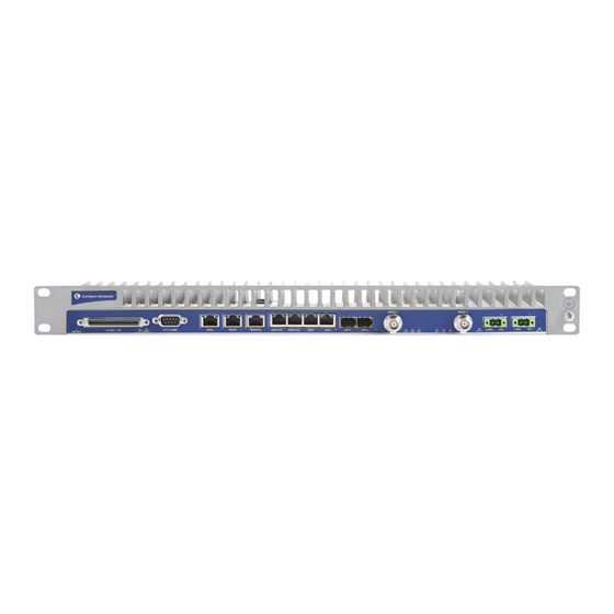
Chapter 4: Installing the PTP 820G This section provides instructions for installing a PTP 820G IDU. Figure 11 IDU (Full Configuration) Kits required to perform the installation Table 8 Required Kits for installation Description Quantity PTP 820G chassis 19" rack / sub-rack Tools •... -
Page 39: Installing The Ptp 820G Idu In The Rack (19")
(not supplied with the installation kit) to fasten the IDU to the rack. If you are installing multiple PTP 820G units in a single rack, make sure to leave a space of 1RU after every two PTP 820G units, as shown in the figure below. This restriction also applies to PTP 820G units installed in proximity with third party units. -
Page 40: Grounding The Ptp 820G
Chapter 4: Installing the PTP 820G Unpacking Equipment at the Site Grounding the PTP 820G Connect a grounding wire first to the single-point stud shown in the figure below, and then to the rack, using a single screw and two washers. Verify that the grounding resistance is 0-2 ohms. -
Page 41: Chapter 5: Connecting Power Cable
Chapter 5: Connecting Power Cable Caution Before connecting the power supply to the PTP 820G unit, you must verify that the positive pole in the external power supply is grounded! Power supply grounding must be in according with the following figure: Figure 12 Power Supply Grounding PTP 820G utilizes two power interface for power redundancy. - Page 42 Insert the wires into the connector. Secure the wires in the connector with the screws. Plug the connector into the PTP 820G power interface and tighten the two screws on the sides of the connector to secure the connector. phn-3967_005v000...
-
Page 43: Power Supply Notes
Chapter 5: Connecting Power Cable Power Supply Notes Power Supply Notes When selecting a power source, the following must be considered: • Voltage range: -40 VDC to -60 VDC. • Recommended: Availability of a UPS (Uninterrupted Power Source), battery backup, and emergency power generator. -
Page 44: Chapter 6: Cabling Requirements For Unit Redundancy
Chapter 6: Cabling Requirements for Unit Redundancy phn-3967_005v000 Page 6-1... -
Page 45: Cabling For Ethernet Interfaces
Table 9 Y-Cable for Electrical Splitter Mode FE Traffic Interface Protection Part Number Description C000082L153A PTP 820G Fast Ethernet Protection Y-cable, 1.34m, Cat5E No special cabling is required for other Ethernet protection modes. phn-3967_005v000 Page 6-2... -
Page 46: Cabling For E1/Ds1 Interfaces
If the E1/DS1 interfaces are being used, a Y-cable is used to connect the active and standby E1/DS1 interfaces. The following table shows the Part Number and Marketing Model of the Y-cable required for E1/DS1 protection. Table 10 Y-Cable for E1/DS1 Protection Part Number Description C000082L154A PTP 820G TDM Protection Y cable, 0.6m,120 ohm phn-3967_005v000 Page 6-3... -
Page 47: Cabling For T3 Synchronization
Chapter 6: Cabling Requirements for Unit Redundancy Cabling for T3 Synchronization Cabling for T3 Synchronization If T3 synchronization input is being used, a Y cable is used to connect to the active and standby Sync interfaces. phn-3967_005v000 Page 6-4... -
Page 48: Inter-Idu Protection Connectivity And Management
PTP 820G units in a redundancy configuration must have their CPUs interconnected in order to synchronize their protection status. The same IP address is used for both PTP 820G units, to ensure that management is not lost in the event of switchover. A special cable is required to enable this connectivity. -
Page 49: Chapter 7: Performing Initial Configuration
Inter-IDU Protection Connectivity and Management Chapter 7: Performing Initial Configuration This section describes how to establish a management connection with the PTP 820G unit and lists the configuration steps that must be performed in order to enable basic radio connectivity. For detailed configuration instructions, refer the PTP 820G User Guide. -
Page 50: Establishing A Connection
Chapter 7: Performing Initial Configuration Establishing a Connection Establishing a Connection You can connect to the PTP 820G unit using a TP cable with a LAN connection or using a Serial RS- 232 cable. Connecting to the Unit with a Serial Connection Connect an RS-232 cable with an RJ-45 interface from your laptop or PC to the Terminal Interface on the PTP 820G front panel. -
Page 51: Figure 15 Management Interface
To establish a connection between the PC and the PTP 820G unit, it is necessary to have an IP address on the PC within the same subnet as the unit. The default IP address of the PTP 820G unit is 192.168.1.1. Set the PC address to e.g. 192.168.1.10 and subnet mask to 255.255.255.0. -
Page 52: Logging On
Chapter 7: Performing Initial Configuration Logging On Logging On Open a browser (e.g. Internet Explorer, Mozilla Firefox etc). Type in the default IP address "192.168.1.1" in the Address Bar. Login Window Enter the following values: User Name: admin Password: admin Click Apply. -
Page 53: Changing Your Password
In addition to the Admin password, there is an additional password protected user account, “root user”, which is configured in the system. The root user password and instructions for changing this password are available from Cambium Networks Customer Support. It is strongly recommended to change this password. -
Page 54: Configuration
Chapter 7: Performing Initial Configuration Configuration Configuration Before connection over the radio hop is established, it is of high importance that the elements are assigned a dedicated IP address, according to an IP plan for the total network. Note If connection over the hop is established with identical IP addresses, an IP address conflict will occur and remote connection to the element on the other side of the hop may be lost. -
Page 55: Chapter 8: Specifications
Chapter 8: Specifications Environmental Specifications for IDU • Operating: ETSI EN 300 019-1-3 Class 3.2 • Temperature: -5C (23F) to 55C (131F) – Temperature range for continuous operating temperature with high reliability. -25C (-13F) to 65C (149F) – Temperature range for exceptional temperatures, tested successfully, with limited margins. -
Page 56: Power Consumption Specifications
Mounting OD Pole size) Power Consumption Specifications The following table shows the maximum power consumption for PTP 820G IDU and supported RFUs. The maximum power consumption for the entire system is the sum of the IDU and the RFUs connecting to it. -
Page 57: Chapter 9: Acceptance & Commissioning Procedures
Procedure for PTP 820. Acceptance and commissioning should be performed after initial setup is complete. The purpose of this procedure is to verify correct installation and operation of the installed link and the interoperability with customer end equipment. Cambium Networks’ Acceptance and Commissioning procedure includes the following stages: • Site Acceptance Procedure •... -
Page 58: Site Acceptance Procedure
Chapter 9: Acceptance & Commissioning Procedures Site Acceptance Procedure Site Acceptance Procedure The purpose of the following procedures is to verify that all installation requirements were noted and checked. Following this procedure will ensure proper, long-lasting, and safe operation of the product. - Page 59 Chapter 9: Acceptance & Commissioning Procedures Site Acceptance Procedure (Direct or Remote Type of RFU mount: mount) RFU is securely mounted to the antenna or pole RFU is grounded as per installation instructions RFU‘s polarization is as per link requirements RFU is installed properly and has no physical damage For Remote-Mount Only: Remote mount kit is securely mounted to the pole...
- Page 60 Chapter 9: Acceptance & Commissioning Procedures Site Acceptance Procedure SITE ACCEPTANCE CHECKLIST (continued) 6. FLEXIBLE WAVEGUIDE Overall flexible WG length: Flexible WG type: Flexible WG is connected securely to RFU and Antenna Flexible WG connector is weather-proofed (sealed) at the RFU At the RFU, the flexible WG has a service/drip loop to prevent moisture from entering the connector Flexible WG is secured using suitable restraints to fixed points at regular...
- Page 61 Chapter 9: Acceptance & Commissioning Procedures Site Acceptance Procedure SITE ACCEPTANCE CHECKLIST (continued) 10. REMARKS/NOTES 11. GENERAL INFORMATION Name: Title: Site accepted by: Company: Signature: Date: Name: Title: Site approved by: Company: Signature: Date: phn-3967_005v000 Page 9-7...
-
Page 62: Site Acceptance Checklist Notes
Chapter 9: Acceptance & Commissioning Procedures Site Acceptance Checklist Notes Site Acceptance Checklist Notes The following notes provide important additional information about the Site Acceptance Checklist. 1. Antenna Mounting Mounting pole is of sufficient height to clear local obstructions, such as parapets, window cleaning gantries, and lift housings. - Page 63 Chapter 9: Acceptance & Commissioning Procedures Site Acceptance Checklist Notes Typical labeling requirements include: • Antenna labels - for link identity and bearing • RFU labels - for link identity, frequency, and polarization • Coax cable labels - for link identity, close to the RFU, IDU, and either end of any joint •...
-
Page 64: Radio Link Commissioning Procedure
Chapter 9: Acceptance & Commissioning Procedures Radio Link Commissioning Procedure Radio Link Commissioning Procedure Scope This section describes the recommended commissioning tests for PTP 820 radio link in a 1+0 configuration. The purpose of the commissioning tests is to verify correct and proper operation of the product. Commissioning Test The following tests should be performed on each installed link. - Page 65 Chapter 9: Acceptance & Commissioning Procedures Radio Link Commissioning Procedure • If the management station is located at a remote site (Network Operation Center), verify that the management station can manage the link and receive traps. phn-3967_005v000 Page 9-11...
-
Page 66: Ptp 820 Commissioning Log
Maintaining the Commissioning Log is important for tracking your installations, and to provide essential data for Cambium Networks. Upon completing the Commissioning Log, send the log to Cambium Networks’ support center at support@cambium.com. PTP 820 LINK COMMISSIONING LOG 1. - Page 67 Chapter 9: Acceptance & Commissioning Procedures PTP 820 Commissioning Log Site 1 Site 2 3. ANTENNA AND RFU MOUNT Antenna vendor and model: Antenna size: Mounting type: Mounting losses: Site 1 Site 2 4. LINK PARAMETERS Link distance: Rain zone: Expected RSL (dBm): Expected Diversity RSL (dBm): RSL Main (dBm):...
- Page 68 Chapter 9: Acceptance & Commissioning Procedures PTP 820 Commissioning Log Signature: Name: Company: Commissioned by: Date: Signature: phn-3967_005v000 Page 9-14...
Need help?
Do you have a question about the PTP 820G and is the answer not in the manual?
Questions and answers