
Related Manuals for Allied Telesis SwitchBlade x3100 Series


Summary of Contents for Allied Telesis SwitchBlade x3100 Series
- Page 1 Software Reference for SwitchBlade® x3100 Series Switches - Release 14.2 - Issue 2 Software Reference for SwitchBlade® x3100 Series Switches - Release 14.2...
- Page 2 Allied Telesis, Inc. Adobe, Acrobat, and Reader are either registered trademarks or trademarks of Adobe Systems Incorporated in the United States and/or other countries.
-
Page 3: Table Of Contents
2.4 XE Interfaces - - - - - - - - - - - - - - - - - - - - - - - - - - - - - - - - - - - - - - - - - - - - - - - - - - - - - 2-7 Software Reference for SwitchBlade x3100 Series (Table of Contents - General) - Page 4 6.7 Priority Queuing - - - - - - - - - - - - - - - - - - - - - - - - - - - - - - - - - - - - - - - - - - - - - - - - - - 6-68 TOC-2 Software Reference for SwitchBlade x3100 Series (Table of Contents - General)
- Page 5 8.12 Routine Procedures - - - - - - - - - - - - - - - - - - - - - - - - - - - - - - - - - - - - - - - - - - - - - - 8-53 TOC-3 Software Reference for SwitchBlade x3100 Series (Table of Contents - General)
-
Page 6: Software Reference For Switchblade X3100 Series (Table Of Contents - General)
TOC-4 Software Reference for SwitchBlade x3100 Series (Table of Contents - General) -
Page 7: Chassis Configuration - - - - - - - - - - - - - - - - - - - - - - - - - - - - - - - - - - - - - - - - - - - - - -
1.5.1 Users and Privileges - - - - - - - - - - - - - - - - - - - - - - - - - - - - - - - - - - - - - - - - - - - 1-22 Software Reference for SwitchBlade x3100 Series (Table of Contents) -
Page 8: Configuring Physical Interfaces And Protocols - - - - - - - - - - - - - - - - - - - - - - - - - - - -
1.9 Database and Text File Management - - - - - - - - - - - - - - - - - - - - - - - - - - - - - - - - - - - 1-120 TOC-2 Software Reference for SwitchBlade x3100 Series (Table of Contents) -
Page 9: Control Module Management - - - - - - - - - - - - - - - - - - - - - - - - - - - - - - - - - - - - - -
1.11.3 Controlling Output of Logs - - - - - - - - - - - - - - - - - - - - - - - - - - - - - - - - - - - - 1-160 TOC-3 Software Reference for SwitchBlade x3100 Series (Table of Contents) -
Page 10: Led Management - - - - - - - - - - - - - - - - - - - - - - - - - - - - - - - - - - - - - - - - - - - - - -
1.15.4 System Cooling Command List - - - - - - - - - - - - - - - - - - - - - - - - - - - - - - - - - - 1-217 TOC-4 Software Reference for SwitchBlade x3100 Series (Table of Contents) -
Page 11: Introduction - - - - - - - - - - - - - - - - - - - - - - - - - - - - - - - - - - - - - - - - - - - - - - - - - - - - -
2.4.3 Interface (Common) Command List - - - - - - - - - - - - - - - - - - - - - - - - - - - - - - - - - 2-9 TOC-5 Software Reference for SwitchBlade x3100 Series (Table of Contents) -
Page 12: Power Over Ethernet (Poe) - - - - - - - - - - - - - - - - - - - - - - -
4.3 Link Aggregation (LAG) - - - - - - - - - - - - - - - - - - - - - - - - - - - - - - - - - - - - - - - - - - - - 4-23 TOC-6 Software Reference for SwitchBlade x3100 Series (Table of Contents) -
Page 13: Vlan (802.3) - - - - - - - - - - - - - - - - - - - - - - - - - - - - - - - - - - - - - - - - - - - - - - - - - - - -
4.5.8.2 Provisioning Parameters - - - - - - - - - - - - - - - - - - - - - - - - - - - - - - - - - - - 4-82 4.5.8.14 MST Configuration Table (Unique for MSTP) - - - - - - - - - - - - - - - - - - - - 4-85 TOC-7 Software Reference for SwitchBlade x3100 Series (Table of Contents) -
Page 14: Ethernet Protection Switched Ring (Epsr) And Superloop Prevention - - - - - - - - - -
4.6.12.2 Configuration Rules - - - - - - - - - - - - - - - - - - - - - - - - - - - - - - - - - - - - - 4-136 TOC-8 Software Reference for SwitchBlade x3100 Series (Table of Contents) -
Page 15: Upstream Forwarding Only (Ufo) Mode - - - - - - - - - - - - - - - - - - - - - - - - - - - - - - -
4.9.7 HVLAN Command List - - - - - - - - - - - - - - - - - - - - - - - - - - - - - - - - - - - - - - - 4-195 TOC-9 Software Reference for SwitchBlade x3100 Series (Table of Contents) -
Page 16: Vlan Translation - - - - - - - - - - - - - - - - - - - - - - - - - - - - - - - - - - - - - - - - - - - - - - -
6.3.1 Classifier Support on the SBx3112 - - - - - - - - - - - - - - - - - - - - - - - - - - - - - - - - - - -6-6 TOC-10 Software Reference for SwitchBlade x3100 Series (Table of Contents) -
Page 17: Access Control List - - - - - - - - - - - - - - - - - - - - - - - - - - - - - - - - - - - - - - - - - - - - - - - -
6.8.2.3 Configuration Procedure - - - - - - - - - - - - - - - - - - - - - - - - - - - - - - - - - - - - 6-76 TOC-11 Software Reference for SwitchBlade x3100 Series (Table of Contents) -
Page 18: Port Authentication - - - - - - - - - - - - - - - - - - - - - - - - - - - - - - - - - - - - - - - - - - - - - - -
6.12.5 Local ARP Discard Command List- - - - - - - - - - - - - - - - - - - - - - - - - - - - - - - - 6-168 TOC-12 Software Reference for SwitchBlade x3100 Series (Table of Contents) -
Page 19: Dynamic Host Configuration Protocol (Dhcp) - - - - - - - - - - - - - - - - - - - - - - - - - - - -
7.4.1.3 LLDP Functional Overview - - - - - - - - - - - - - - - - - - - - - - - - - - - - - - - - - 7-71 TOC-13 Software Reference for SwitchBlade x3100 Series (Table of Contents) -
Page 20: Remote Network Monitoring (Rmon) - - - - - - - - - - - - - - - - - - - - - - - - - - - - - - - - - -
7.7.4.4 BFD with XE4 Interfaces - - - - - - - - - - - - - - - - - - - - - - - - - - - - - - - - - - - 7-122 TOC-14 Software Reference for SwitchBlade x3100 Series (Table of Contents) -
Page 21: Alarm System Features - - - - - - - - - - - - - - - - - - - - - - - - - - - - - - - - - - - - - - - - - - - - - -
8.10.3 Optics Data Output Examples- - - - - - - - - - - - - - - - - - - - - - - - - - - - - - - - - - - - 8-47 TOC-15 Software Reference for SwitchBlade x3100 Series (Table of Contents) -
Page 22: Viewing The Cpustats (High Water Mark) - - - - - - - - - - - - - - - - - - - - - - - - - - - -
8.12.5 Scripting - - - - - - - - - - - - - - - - - - - - - - - - - - - - - - - - - - - - - - - - - - - - - - - - - - 8-57 Appendix A: Command List 1 TOC-16 Software Reference for SwitchBlade x3100 Series (Table of Contents) - Page 23 Preface I Introduction The Allied Telesis SwitchBlade x3112 leverages widely accepted Ethernet switching technology to allow the network operator to provide Ethernet-based services. It is a feature-rich platform that enables network opera- tors to offer advanced, simultaneous services, such as high quality voice, tiered IP/Ethernet data services, and broadcast quality IP video.
- Page 24 When viewing this document in pdf, you can go to the previous viewed pdf page by using Alt / left Note: arrow. (Use Alt / right arrow to go to the following viewed pdf page.) Software Reference for SwitchBlade x3100 Series Switches (Preface)
- Page 25 Database backup / purge / restore - Chapter 1 - 1.9.1 Chapter 1 - Set- Text Config Files (backup, editing, restore) - Chap- ting up the ter 1 - 1.9.2 SBx3112 (cont.) Software Reference for SwitchBlade x3100 Series Switches (Preface)
- Page 26 Power over the connected device does not support PoE, Ethernet (PoE) the user must disable PoE to turn off the alarm. GE24POE can face upstream or downstream GE24POE can provide upstream LAG Software Reference for SwitchBlade x3100 Series Switches (Preface)
- Page 27 VLAN Translation - Chapter 4 - 4.10 On SBx3100: - 2048 per XE interface - 16 per GE24xxx interface Chapter 5 - Multicast Stream availability - Chapter 5 - 512 Multicast groups per system IGMP Software Reference for SwitchBlade x3100 Series Switches (Preface)
- Page 28 LLDP - Chapter 7 - RMON Statistics - Chapter 7 - 7.5.2 Based on RFC3176 Controlling RMON - Chapter 7 - 7.5.4 IP Statistics - Chapter 7 - BFD - Chapter 7 - Software Reference for SwitchBlade x3100 Series Switches (Preface)
- Page 29 Optic Module Information Access - Chapter 8 - 8.10 View CPUStats - Chapter 8 - 8.11.1 Delete Obsolete users - Chapter 8 - 8.12.3 Delete Obsolete files -Chapter 8 - 8.12.4 Scripting - Chapter 8 - 8.12.5 Software Reference for SwitchBlade x3100 Series Switches (Preface)
- Page 30 Software Reference for SwitchBlade x3100 Series Switches (Preface)
-
Page 31: Setting Up The Switch
• Power Management and System Cooling • Power Supply Command List • System Cooling Command List • Basic Provisioning of Cards and Ports • Card Management Command List • Software Reference for SwitchBlade x3100 Series Switches (Setting Up the Switch) -
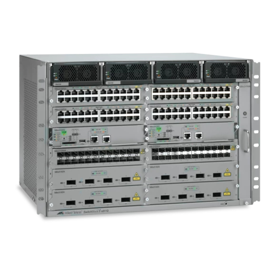
Page 32: Chassis Configuration
SBx3165 SBx3165 SBx3161 SBx3161 SBx31GP24 SBx31FAN SBx31GP24 SBx31XZ4 PORT A C TI V ITY 10G LINK SBx31CFC SBx31GP24 1000 LIN K 10/100 LINK SBx31GS24 SBx3112 SBx3112 Chassis FIGURE 1-1 Software Reference for SwitchBlade x3100 Series Switches (Setting Up the Switch) -
Page 33: Card Representation In Commands
For all of the cards except the power and cooling cards (refer to 1.15.1), a card is referenced by its slot number (such as CARD=4). For CARD there is also ACTCFC and INACTCFC. Refer to SHOW CARD. Software Reference for SwitchBlade x3100 Series Switches (Setting Up the Switch) -
Page 34: Getting Started
The password should be changed to avoid a security risk. * Warning: The password for the user 'manager' is the system default. The password should be changed to avoid a security risk. ************************************************************************* Software Reference for SwitchBlade x3100 Series Switches (Setting Up the Switch) -
Page 35: Initial System Status
Prov FPGA Slot Type Physical Type Model Serial Number CLEI Code Rev Rev ----- ------- -------------- --------- ------------------- ---------- --- ---- GE24POE GE24POE SBx24POE CFC200 CFC200 AT-SBxMFC 51 A042834101200007 Software Reference for SwitchBlade x3100 Series Switches (Setting Up the Switch) - Page 36 Typed in location. Name Typed in name for Allied Telesis SwitchBlade SBx3100 product. Services Service provided by the Allied Telesis SwitchBlade SBx3100 product Description Generic description of the product Software Reference for SwitchBlade x3100 Series Switches (Setting Up the Switch)
-
Page 37: How To Get Command Help
Caution: Always check with the Allied Telesis web site to see which loads should be used so that a later load can be downloaded if necessary. Failure to do this may result in the SBx3112 not being able to provide all the functionality listed for a release. - Page 38 SNMP packet (ENABLED or DISABLED) Community The name of an SNMP community on the device. Access The access rights for the SNMP community (READ-ONLY or READ-WRITE) Software Reference for SwitchBlade x3100 Series Switches (Setting Up the Switch)
- Page 39 The status of the community (ENABLED or DISABLED) PARAMETERS: SNMP - The SNMP parameter indicates the kind of SHOW operation performed. SEE ALSO: ADD SNMP COMMUNITY CREATE SNMP COMMUNITY DELETE SNMP COMMUNITY (etc.) Software Reference for SwitchBlade x3100 Series Switches (Setting Up the Switch)
-
Page 40: Cli Introduction
Throughout this document, all syntax will try to use complete words, with verbs and parameters in Note: upper case and the pairing of parameters and values with equal signs. 1-10 Software Reference for SwitchBlade x3100 Series Switches (Setting Up the Switch) -
Page 41: Control Of Cli Command Confirmation
Security Officer User Privilege..SECURITY Status..Enabled Logins..2 OFFICER Telnet User... Yes Last Login... 2004-06-17 Fails..0 11:18:54 Lockouts... 0 ------------------------------------------------------------------------------- ------------------------------------------------------------------------------- No Transfer in progress ------------------------------------------------------------------------------- 1-11 Software Reference for SwitchBlade x3100 Series Switches (Setting Up the Switch) -
Page 42: Command Alias
Command Alias 1.4.5 Command Alias Command alias functionality allows Allied Telesis Network Access product users to define shortcuts to com- mand strings to simplify the use of the CLI. It allows users to create shortcut strings which can be typed in place of commonly used (longer) commands. -
Page 43: Configuring An Alias
This section describes configuration information, procedures, and commands for a Command Alias. 1.4.6.1 Default Configuration Certain aliases will be created by the Allied Telesis Network Access product upon system start-up. These default aliases are illustrated below (they are displayed using the SHOW ALIAS command): >SHOW ALIAS... - Page 44 If the user does not have the privilege level required for the command, command execution will fail. This will be discussed in more detail later in this subsection. Alias names must be alphanumeric. • 1-14 Software Reference for SwitchBlade x3100 Series Switches (Setting Up the Switch)
- Page 45 Show the alias string SHOW ALIAS=dm dm=”disable more” Create an alias command with input variables CREATE ALIAS=shcard STRING=”SHOW CARD=$1” Use this alias to view the information about card 4 shcard 4 1-15 Software Reference for SwitchBlade x3100 Series Switches (Setting Up the Switch)
-
Page 46: Alias Command List
This section describes the commands available for using the CLI (Alias) Alias Commands TABLE 1-5 Commands CREATE ALIAS STRING DESTROY ALIAS RENAME ALIAS TO SETDEFAULTS ALIAS SHOW ALIAS 1-16 Software Reference for SwitchBlade x3100 Series Switches (Setting Up the Switch) -
Page 47: Create Alias String
, etc. This command may be ADD, DELETE, SHOW, SET executed by users with a MANAGER privilege level or higher. Example CREATE ALIAS=su STRING="show user $1;show sys userconfig" 1-17 Software Reference for SwitchBlade x3100 Series Switches (Setting Up the Switch) - Page 48 This command may be executed by users with a MANAGER privilege level or higher. The value can be one alias, more then one alias sepa- rated by a comma, or ALL. Example DESTROY ALIAS=su,manage 1-18 Software Reference for SwitchBlade x3100 Series Switches (Setting Up the Switch)
- Page 49 Default Value ALIAS The name of the alias to be renamed The renamed alias. It must match the same naming rules as the original one. Example RENAME ALIAS=su TO=super 1-19 Software Reference for SwitchBlade x3100 Series Switches (Setting Up the Switch)
- Page 50 The default alias commands consist of "showdebug" which references a set of other alias commands, used to display all system information. Options Example SETDEFAULTS ALIAS 1-20 Software Reference for SwitchBlade x3100 Series Switches (Setting Up the Switch)
- Page 51 The value can be one alias, more then one alias sepa- rated by a comma, or ALL Example >SHOW ALIAS=showvc --- Alias Commands --------------------------------- Alias Name Substitution String ----------------------- --------------------------- showvc....show vc interface all full; 1-21 Software Reference for SwitchBlade x3100 Series Switches (Setting Up the Switch)
-
Page 52: Users And Privileges
Manager privileges, Security Officers can add, remove, or modify other user accounts, as well as create, modify, and destroy management features. When logged in, the Security Officer receives the com- mand-line prompt: 1-22 Software Reference for SwitchBlade x3100 Series Switches (Setting Up the Switch) -
Page 53: Customizing The Cli Prompt
Note: Spaces are not allowed in user names and passwords. Note: 1.5.2 Customizing the CLI Prompt When the user logs into the Allied Telesis system, a default CLI prompt is provided as displayed here: Username: officer Password: officer SEC>> <----------- CLI prompt The user has the ability to provision or customize the system CLI prompt. - Page 54 SEC>> SET PROMPT="%t" Info (010017): Operation Successful 15:40:24>> 15:40:25>> Reset the CLI prompt: 15:40:26>> SETDEFAULTS PROMPT Info (010017): Operation Successful Set the CLI prompt to the Security Officer: 1-24 Software Reference for SwitchBlade x3100 Series Switches (Setting Up the Switch)
-
Page 55: Provisioning The Login Banner
1.5.3.1 Introduction The login banner appears as the first system output presented to a user when they log into the Allied Telesis system. The user has the ability to provision or customize the system login banner. The banner could be changed to present a message to all users or a message of the day. -
Page 56: Password Recovery
Since all system user IDs and passwords have been destroyed, there is no user access to the CLI command line prompt to initiate a reboot from software using the RESTART command. Therefore, the system must be power-cycled. Refer to 1.5.5.3. 1-26 Software Reference for SwitchBlade x3100 Series Switches (Setting Up the Switch) -
Page 57: Password Recovery Procedure
'.' = clear field; '-' = go to previous field; ^D = quit BOOTSERVER NAME BOOTSERVER IPADDR : 10.52.18.3 NETWORKLOAD : /tffs/load/cfc200_14.1.0.GAMMA.20100303.tar HOSTNAME MGMT IPADDR : 10.52.71.36 GATEWAY IPADDR : 10.52.71.1 1-27 Software Reference for SwitchBlade x3100 Series Switches (Setting Up the Switch) - Page 58 @@@@@@@@@@@" "@@@@@ " @@@@@@@@@@@@@" Allied Telesis, Inc. ATI 200G Central Fabric Controller Version 14.1.0.GAMMA.20100303 (Lab-Only Build) Created on Wed 03/03/2010 at 04:10 AM Copyright Allied Telesis Inc., 2009 1-28 Software Reference for SwitchBlade x3100 Series Switches (Setting Up the Switch)
- Page 59 Note that there is a security risk if the default user ID and password are enabled. It should be modified as soon as possible or the default “officer” and “manager” accounts should be replaced by a different SECU- RITY OFFICER account. 1-29 Software Reference for SwitchBlade x3100 Series Switches (Setting Up the Switch)
- Page 60 Username Privilege Status Telnet SSH Last Login --------------------- ---------------- -------- ------ --- ------------------- officer SECURITY OFFICER Enabled Yes 2010-04-21 07:11:50 manager SECURITY OFFICER Enabled Yes 2010-04-21 07:11:58 ------------------------------------------------------------------------------- 1-30 Software Reference for SwitchBlade x3100 Series Switches (Setting Up the Switch)
-
Page 61: User Administration Commands
RESET USER (SEC) SEND MESSAGE SESSION SET PASSWORD SET SYSTEM LANGUAGE SET SYSTEM USERCONFIG (SEC) SET SYSTEM USERCONFIG (SEC) SET USER (SEC) SETDEFAULTS LOGIN BANNER (SEC) SHOW SYSTEM USERCONFIG (SEC) 1-31 Software Reference for SwitchBlade x3100 Series Switches (Setting Up the Switch) - Page 62 YES - The account can be used immediately after it is created. NO, FALSE, or OFF - the account cannot be used to access the system. 1-32 Software Reference for SwitchBlade x3100 Series Switches (Setting Up the Switch)
- Page 63 Indicates the date that the user account is to be deacti- vated. The default value is OFF, which indicates that there is no deactivation date. Example ADD USER coleman PASSWORD cac1cacX TELNET=YES 1-33 Software Reference for SwitchBlade x3100 Series Switches (Setting Up the Switch)
-
Page 64: Deactivate Session (Sec)
SAGE options can be used. If delayed deactivation is used, the deactivation can be aborted through the use of the CANCEL option. Example DEACTIVATE SESSION=ALL MESSAGE=Reboot in 60 seconds DELAY=60 1-34 Software Reference for SwitchBlade x3100 Series Switches (Setting Up the Switch) - Page 65 (if applicable). Option Description Default Value USER The login id that was configured Example >DELETE USER=coleman Delete User (Y/N)? Y Info (020100): User "coleman" has been deleted 1-35 Software Reference for SwitchBlade x3100 Series Switches (Setting Up the Switch)
- Page 66 Used to suppress user confirmation prompts for potentially dangerous commands. This Description command is intended for expert users who understand the impact of the various opera- tions on the device. Options Example DISABLE CONFIRMATION 1-36 Software Reference for SwitchBlade x3100 Series Switches (Setting Up the Switch)
- Page 67 The disabling of the MORE prompt via this command will only affect the cur- rent CLI session. The MORE prompt can be re-enabled via the ENABLE MORE com- mand. Options Example DISABLE MORE 1-37 Software Reference for SwitchBlade x3100 Series Switches (Setting Up the Switch)
- Page 68 The following table gives the range of values for each option that can be specified with Options this command and a default value (if applicable). Option Description Default Value USER The login name of the user Example DISABLE USER=coleman 1-38 Software Reference for SwitchBlade x3100 Series Switches (Setting Up the Switch)
- Page 69 No other user sessions are altered or changed. When a user logs out, the confirmation settings are automatically restored to enable confirmation prompts. Options Example ENABLE CONFIRMATION 1-39 Software Reference for SwitchBlade x3100 Series Switches (Setting Up the Switch)
- Page 70 BY doing so, the data will be displayed to the screen in its entirety. The MORE prompt can be re-enabled via the ENABLE MORE command. Options Example ENABLE MORE 1-40 Software Reference for SwitchBlade x3100 Series Switches (Setting Up the Switch)
- Page 71 The following table gives the range of values for each option that can be specified with Options this command and a default value (if applicable). Option Description Default Value USER The login name of the user Example ENABLE USER=coleman 1-41 Software Reference for SwitchBlade x3100 Series Switches (Setting Up the Switch)
- Page 72 Deletes all users from the database and recreates the default Security Officer user. Glo- Description bal configuration parameters and counters are not affected. To clear these counters use the RESET USER command. Options Example PURGE USER 1-42 Software Reference for SwitchBlade x3100 Series Switches (Setting Up the Switch)
- Page 73 If GLOBAL is specified, the global counters for the User Authentication Facility are reset. If ALL is specified, all counters are reset. Example RESET USER COUNTER=ALL 1-43 Software Reference for SwitchBlade x3100 Series Switches (Setting Up the Switch)
- Page 74 (0) or one of the 10 telnet sessions ALL sends the message to all sessions Example SEND MESSAGE=”reboot in 5 minutes” SESSION=ALL 1-44 Software Reference for SwitchBlade x3100 Series Switches (Setting Up the Switch)
- Page 75 STRING value is 255 characters. Security Level The USER, MANAGER, SECURITYOFFICER and ALL parameters define which user level(s) the log- inbanner is applied to. Example SET LOGINBANNER STRING="Allied Telesis SBx3112" 1-45 Software Reference for SwitchBlade x3100 Series Switches (Setting Up the Switch)
- Page 76 Allows Users to change their password at anytime. The command prompts for the old Description password and asks to reconfirm the new password. Options Example SET PASSWORD Enter Old Password: Enter New Password: Re-enter New Password: Password successfully changed 1-46 Software Reference for SwitchBlade x3100 Series Switches (Setting Up the Switch)
- Page 77 The following table gives the range of values for each option that can be specified with Options this command and a default value (if applicable). Option Description Default Value LANGUAGE English (EN) is the only language supported currently. Example 1-47 Software Reference for SwitchBlade x3100 Series Switches (Setting Up the Switch)
-
Page 78: Set System Userconfig (Sec)
If the value is set to YES, then the user will be prompted for a new password when they first log in. 1-48 Software Reference for SwitchBlade x3100 Series Switches (Setting Up the Switch) - Page 79 Password Recovery Introduction Example SET SYSTEM USERCONFIG LOGINFAIL=10 LOCKOUTPD=120 MANPWD- FAIL=3 SECUREDELAY=0 MINPWDLEN=3 PERSISTTIMER=1440 PWDAGE- ING=OFF FORCEPWDCHANGE=No 1-49 Software Reference for SwitchBlade x3100 Series Switches (Setting Up the Switch)
- Page 80 Detrmines whether or not the password is encrypted: CLEARTEXT CLEARTEXT - Non-encrypted text MD5 - Pre-encrypted as a 32 character MD5 digest. Example SET SYSTEM USERCONFIG MANAGERPASSWORD=classified SECURITYOF- FICERPASSWORD=NONE FORMAT=CLEARTEXT 1-50 Software Reference for SwitchBlade x3100 Series Switches (Setting Up the Switch)
-
Page 81: Set User (Sec)
Indicates the number of days before a password expires and requires the user to change its password. If the value is OFF or 0, then the password does not expire. 1-51 Software Reference for SwitchBlade x3100 Series Switches (Setting Up the Switch) - Page 82 Indicates the date that the user account is to be deacti- vated. The default value is OFF, which indicates that there is no deactivation date. Example SET USER coleman PASSWORD cac2cacY TELNET=NO 1-52 Software Reference for SwitchBlade x3100 Series Switches (Setting Up the Switch)
- Page 83 Security Level The level in which the default banner is set. If ALL parameter is provided, all user levels are reset to the default loginbanner. Example SETDEFAULTS LOGINBANNER 1-53 Software Reference for SwitchBlade x3100 Series Switches (Setting Up the Switch)
- Page 84 (in minutes) before a telnet session times out • value of Persist Timer (in minutes) • the RADIUS authentication mode • the TACACS+ authentication mode 1-54 Software Reference for SwitchBlade x3100 Series Switches (Setting Up the Switch)
- Page 85 Pwd changes..0 manager Pwd fails.... 0 unknown login names..0 total Pwd fails....0 idle session timeouts..0 login lockouts....0 database clears....0 default account resets..0 1-55 Software Reference for SwitchBlade x3100 Series Switches (Setting Up the Switch)
-
Page 86: Initial Interfaces
Caution: Only one interface can be enabled at a time; enabling an interface will disable an interface already enabled. If necessary, the ENABLE IP INTERFACE command will automatically disable the other IP Interface. 1-56 Software Reference for SwitchBlade x3100 Series Switches (Setting Up the Switch) -
Page 87: Physical Interface Configuration
1.6.4 Configuring the Management Interfaces 1.6.4.1 Configuration Procedure The following tables show how to configure the MGMT and Inband interface. Caution: Enabling the Inband Interface would disable the MGMT interface. 1-57 Software Reference for SwitchBlade x3100 Series Switches (Setting Up the Switch) - Page 88 Add the VLAN to the Network interface ADD VLAN INBAND INTERFACE 1.0 FRAME TAGGED Add the IP interface to the VLAN ADD IP INTERFACE VLAN:420.0 IPADDRESS 10.51.66.101 SUBNET- MASK 255.255.255.0 IFNAME INBAND 1-58 Software Reference for SwitchBlade x3100 Series Switches (Setting Up the Switch)
-
Page 89: Using The Ping Command
PING 172.16.66.1 (172.16.66.1) 64 bytes from 172.16.66.1 (172.16.66.1): icmp_seq=1 --- 172.16.66.1 ping statistics --- 1 packets transmitted, 1 packets received, 0% packet loss officer SEC>> PING 172.16.66.1 FROM IPADDRESS=172.16.66.240 1-59 Software Reference for SwitchBlade x3100 Series Switches (Setting Up the Switch) - Page 90 PING 172.16.66.1 FROM IPADDRESS=172.16.66.240 officer SEC>> PING 172.16.66.1 (172.16.66.1) 64 bytes from 172.16.66.1 (172.16.66.1): icmp_seq=1 --- 172.16.66.1 ping statistics --- 1 packets transmitted, 1 packets received, 0% packet loss 1-60 Software Reference for SwitchBlade x3100 Series Switches (Setting Up the Switch)
-
Page 91: Ip Interface Commands
IP Interface Commands TABLE 1-9 Commands ADD IP INTERFACE DELETE IP INTERFACE DISABLE IP INTERFACE DISABLE TELNET (SEC) ENABLE IP INTERFACE ENABLE TELNET (SEC) SET IP INTERFACE SHOW IP INTERFACE 1-61 Software Reference for SwitchBlade x3100 Series Switches (Setting Up the Switch) - Page 92 Telnet directly into a MANAGEMENT interface and use it for remote access. NO - The interface cannot be used for MANAGEMENT. Example ADD IP INTERFACE VLAN:420.0 IPADDRESS=10.51.66.101 SUBNETMASK= 255.255.255.0 IFNAME=INBAND 1-62 Software Reference for SwitchBlade x3100 Series Switches (Setting Up the Switch)
- Page 93 (if applicable). Option Description Default Value INTERFACE The interfaces that have been defined. FORCE Overrides the confirmation message. Example DELETE IP INTERFACE=MGMT 1-63 Software Reference for SwitchBlade x3100 Series Switches (Setting Up the Switch)
- Page 94 The following table gives the range of values for each option that can be specified with Options this command and a default value (if applicable). Option Description Default Value INTERFACE The interfaces that have been defined. Example DISABLE IP INTERFACE=MGMT 1-64 Software Reference for SwitchBlade x3100 Series Switches (Setting Up the Switch)
- Page 95 Configuring the Management Interfaces Introduction DISABLE TELNET (SEC) Syntax DISABLE TELNET Allows remote users to telnet to the system. Telnet access is disabled by default. Description Options Example DISABLE TELNET 1-65 Software Reference for SwitchBlade x3100 Series Switches (Setting Up the Switch)
- Page 96 The following table gives the range of values for each option that can be specified with Options this command and a default value (if applicable). Option Description Default Value INTERFACE The provisioned IP interface Example ENABLE IP INTERFACE=VLAN:420.0 1-66 Software Reference for SwitchBlade x3100 Series Switches (Setting Up the Switch)
- Page 97 Configuring the Management Interfaces Introduction ENABLE TELNET (SEC) Syntax ENABLE TELNET Allows remote users to telnet to the system. Telnet access is disabled by default. Description Options Example ENABLE TELNET 1-67 Software Reference for SwitchBlade x3100 Series Switches (Setting Up the Switch)
- Page 98 Telnet directly into a MANAGEMENT interface and use it for remote access. NO - The interface cannot be used for MANAGEMENT. Example SET IP INTERFACE=MGMT IPADDRESS=10.52.70.36 SUBNETMASK=255.255.255.0 MANAGEMENT=YES 1-68 Software Reference for SwitchBlade x3100 Series Switches (Setting Up the Switch)
-
Page 99: Show Ip Interface
--- IP Interfaces --- Interface......VLAN:10.0 (inband) IP State......Enabled Provisioning IP Address...... 10.52.71.108 Subnet Mask..... 255.255.255.0 Gateway......10.52.71.1 DNS......<none> Domain Name..... <none> Card......ACTCFC VLAN ID......10 MGMT......Yes 1-69 Software Reference for SwitchBlade x3100 Series Switches (Setting Up the Switch) -
Page 100: System Time - Sntp
--- System Time --- Date.........2007-01-01 Time......... 11:00:01 (STAN- DARD) UTC Offset......-06:00:00 Day Light Saving Status......ON Time-zone......CENTRAL Start......2ND.SUN.MAR/02:00:00 (2007-03-11) End........ 1ST.SUN.NOV/02:00:00 (2007-11-04) DST UTC Offset..... -05:00:00 1-70 Software Reference for SwitchBlade x3100 Series Switches (Setting Up the Switch) -
Page 101: Configuring Sntp
• 1.6.7.3 Configuration Procedure A typical SNTP configuration procedure involves the following steps: Inputs the hostname or IP address of the SNTP server that the Allied Telesis product will use. • ADD SNTP SERVER Activates the SNTP so that the SBx3112 will be able to synchronize its clock with the SNTP clock. - Page 102 SBx3112 system will use. Enable the SNTP server Activates the SNTP so that the SBx3112 will be ENABLE SNTP able to synchronize its clock with the SNTP clock. Note the results 1-72 Software Reference for SwitchBlade x3100 Series Switches (Setting Up the Switch)
- Page 103 Standard UTC Offset....-05:00:00 SNTP Settings Status........ Change the system time-zone (using a custom UTC offset) Modifies the UTC offset by -01:00. SET SYSTEM TIMEZONE CUSTOM UTCOFFSET -01:00 1-73 Software Reference for SwitchBlade x3100 Series Switches (Setting Up the Switch)
- Page 104 Responses Received Disable the SNTP Deactivates the SNTP so that the SBx3112 will no DISABLE SNTP longer synchronize its clock with the SNTP clock. Delete the SNTP server 1-74 Software Reference for SwitchBlade x3100 Series Switches (Setting Up the Switch)
- Page 105 SHOW SNTP SNTP Configuration ------------------------------------------------------------------------------ Status Local IP 10.52.70.14 Last Update Last Delta Last Status SNTP Server ------------------------------------------------------------------------------ No SNTP Server Configured SNTP Statistics ------------------------------------------------------------------------------ Requests Sent Responses Received 1-75 Software Reference for SwitchBlade x3100 Series Switches (Setting Up the Switch)
-
Page 106: Sntp Commands
This section describes the commands available to enable, configure and manage the IP Interface. SNTP Commands TABLE 1-12 Commands ADD SNTP SERVER DELETE SNTP SERVER DISABLE SNTP ENABLE SNTP RESET SNTP SET SYSTEM SET SYSTEM TIMEZONE SHOW SNTP SHOW SYSTEM TIME 1-76 Software Reference for SwitchBlade x3100 Series Switches (Setting Up the Switch) -
Page 107: Add Sntp Server
Status Local IP 10.52.70.13 Last Update 2009-11-07 11:02:22 DST Last Delta +00.00s Last Status Unknown error SNTP Server ------------------------------------------------------------------------------ 192.43.244.18 SNTP Statistics ------------------------------------------------------------------------------ Requests Sent Responses Received ---------------------------------------------------------------------- 1-77 Software Reference for SwitchBlade x3100 Series Switches (Setting Up the Switch) -
Page 108: Delete Sntp Server
SEC>> sh sntp -------------------------------------------------------- SNTP Configuration ---------------------------------------------------- Status On Local IP 10.52.70.13 Last Update 2009-12-07 09:47:51 Last Delta +00.13s Last Status Operation Successful SNTP Server ---------------------------------------------- (DELETED) 1-78 Software Reference for SwitchBlade x3100 Series Switches (Setting Up the Switch) - Page 109 SNTP server, the disable operation places the client in a state where it can attempt to communicate with the server when ENABLE SNTP is executed. Options Example DISABLE SNTP 1-79 Software Reference for SwitchBlade x3100 Series Switches (Setting Up the Switch)
- Page 110 Activates the SNTP so that theSBx3112 will be able to synchronize its clock with the Description SNTP clock once the SNTP server has been added Options Example ENABLE SNTP 1-80 Software Reference for SwitchBlade x3100 Series Switches (Setting Up the Switch)
- Page 111 Resets the timing counters and sends a query to the SNTP server to re-establish the Description time. Note that the SNTP server must be in use. Options Example RESET SNTP 1-81 Software Reference for SwitchBlade x3100 Series Switches (Setting Up the Switch)
- Page 112 2010-01-01 for January 1, 2010. Setting the system date is immediately reflected in all system output that contains date, such as logs, SNMP traps, etc. Example SET SYSTEM TIME=08:30:00 DATE=2010-08-05 1-82 Software Reference for SwitchBlade x3100 Series Switches (Setting Up the Switch)
-
Page 113: Set System Timezone
02:00:00 respectively. CUSTOM Specifies a value (hour and minutes) to be used as the UTCOFFSET UTC offset. The offset can be any value between -23:59 and +23:59 (e.g., +5:45). 1-83 Software Reference for SwitchBlade x3100 Series Switches (Setting Up the Switch) - Page 114 UTC offset when DST is in effect. The offset can be any value between -23:59 and +23:59 (e.g., +5:45). Turn the Daylight Saving Time feature on or off. 1-84 Software Reference for SwitchBlade x3100 Series Switches (Setting Up the Switch)
- Page 115 Configuring SNTP Introduction Example SET SYSTEM TIMEZONE EASTERN DSTSTART=2ND.SUN.MAR DSTEND=1ST.SUN.NOV DSTUTCOFFSET=-04:00 DST=ON 1-85 Software Reference for SwitchBlade x3100 Series Switches (Setting Up the Switch)
- Page 116 Local IP 10.52.70.13 Last Update 2009-12-07 09:47:51 Last Delta +00.13s Last Status Operation Successful SNTP Server ----------------------------------------------------------------------- 192.43.244.18 SNTP Statistics --------------------------------------------------------------- Requests Sent 1 Responses Received 1 --------------------------------------------------------------- 1-86 Software Reference for SwitchBlade x3100 Series Switches (Setting Up the Switch)
-
Page 117: Show System Time
Time......... 11:12:29 (STANDARD) Current UTC Offset....+00:00:00 Day Light Saving Status......OFF Timezone......CUSTOM Start......- End........ - DST UTC Offset..... +00:00:00 Standard UTC Offset....+00:00:00 SNTP Settings Status......OFF 1-87 Software Reference for SwitchBlade x3100 Series Switches (Setting Up the Switch) -
Page 118: Load File Names
Consider the load file names listed above. The load release is subdivided into three levels. The release level will be important and will be referred to during a software upgrade. They are as follows: 1-88 Software Reference for SwitchBlade x3100 Series Switches (Setting Up the Switch) -
Page 119: File Storage
When performing an upgrade, management commands retrieve the new release files from a network host and load them into FLASH memory on the control module and service module. 1.7.4 CFC Media (SD Card) The media card is an SD card. 1-89 Software Reference for SwitchBlade x3100 Series Switches (Setting Up the Switch) - Page 120 Device Name Fault No Faults Parent Card Card Type SD MEDIA State Status Online Serial Number 1894278981 Firmware Version Number of Sectors 3862528 Bytes per Sector Model SD02G ------------------------------------------------------------------------- 1-90 Software Reference for SwitchBlade x3100 Series Switches (Setting Up the Switch)
- Page 121 File........Size KiB -------------------------------------- --------------------------------------- AllMsg.log......207 DBBackupTR15.db....... 670 RobSD.txt......<1 cfc200_14.1.0.GAMMA.20100203.tar..13359 rob.tar....... 2097 Capacity KiB......3567616 Total Displayed KiB....16334 Available KiB......4194303 delete file sd5:john.scr 1-91 Software Reference for SwitchBlade x3100 Series Switches (Setting Up the Switch)
- Page 122 Copies file “D104_14.1.0.cfg” from the local copy file D104_14.1.0.cfg to sd5: flash to the SD5 media card. Info (033019): Successfully copied file D104_14.1.0.cfg to D104_14.1.0.cfg media sd5 Verify that file was copied 1-92 Software Reference for SwitchBlade x3100 Series Switches (Setting Up the Switch)
- Page 123 CFCs (card 4 and card 5) and changes the filename to “D104_today.cfg“. Info (033006): Successfully copied file D104.cfg to D104_today.cfg card 4 Info (033011): Successfully transferred file: D104_today.cfg to card 5 1-93 Software Reference for SwitchBlade x3100 Series Switches (Setting Up the Switch)
-
Page 124: Transferring Files Between A Tftp Server And An Sd Card
Transfers file “D104_14.1.0.cfg“ from SD card put file sd5:D104_14.1.0.cfg tftp server (SD5) to the TFTP server. 10.52.65.42 Copy a file from SD card to a TFTP server and change the filename 1-94 Software Reference for SwitchBlade x3100 Series Switches (Setting Up the Switch) - Page 125 File........Size KiB -------------------------------------- --------------------------------------- AllMsg.log......207 D104.cfg......59 backup.cfg......62 DBBackupTR15.db....... 670 RobSD.txt......<1 cfc200_14.1.0.GAMMA.20100203.tar..13359 rob.tar....... 2097 Capacity KiB......3567616 Total Displayed KiB....16456 Available KiB......4194303 1-95 Software Reference for SwitchBlade x3100 Series Switches (Setting Up the Switch)
-
Page 126: File Management Command List
DELETE NONPREFLOADS EXECUTE SCRIPT GET FILE PUT FILE PUT FILE CARD RENAME FILE TO SHOW FILE OPERATIONS SHOW FILES SHOW FLASH SHOW MEDIA SHOW SCRIPT SHOW TRANSFER STOP TRANSFER 1-96 Software Reference for SwitchBlade x3100 Series Switches (Setting Up the Switch) -
Page 127: Audit Files
0xdeadbeef Pass 0xdeadbeef xe4_14.1.0.GAMMA.20100202.tar. No Pass 0xdeadbeef Pass 0xdeadbeef xe4_14.1.0.dhays4.20100319.tar No Pass 0xdeadbeef Pass 0xdeadbeef xe4_14.2.0.dhays1.20100325.tar No Pass 0xdeadbeef Pass 0xdeadbeef xe4_14.2.0.dhays1.20100326.tar No Pass 0xdeadbeef Pass 0xdeadbeef --------------------------------------------------------------------------- 1-97 Software Reference for SwitchBlade x3100 Series Switches (Setting Up the Switch) - Page 128 SD card and the number of the CFC slot (e.g., SD4). If only the filename is specified, the file is copied to FLASH memory. Example COPY FILE SD5:D104.CFG TO D104.CFG 1-98 Software Reference for SwitchBlade x3100 Series Switches (Setting Up the Switch)
- Page 129 One or more filenames to be deleted. Wildcards can be used for multiple files. The unit is the SD unit on the active CFC. FORCE Suppresses the confirmation message. Example DELETE FILES SD5:D104.CFG FORCE 1-99 Software Reference for SwitchBlade x3100 Series Switches (Setting Up the Switch)
- Page 130 For an SBx3112 with redundant CFCs, the operation is performed on both CFCs when they are both ONLINE. Options Example DELETE NONPREFLOADS 1-100 Software Reference for SwitchBlade x3100 Series Switches (Setting Up the Switch)
- Page 131 The following table gives the range of values for each option that can be specified with Options this command and a default value (if applicable). Option Description Default Value filename The filename that contains the scripting commands. Example EXECUTE SCRIPT CLIENT_EPSR_SETUP 1-101 Software Reference for SwitchBlade x3100 Series Switches (Setting Up the Switch)
- Page 132 The password needed after entering the user id to gain access to the specified server The SD card that will receive the file from the specified server. Example GET FILE D104_14.1.0_19JULY.CFG TFTP SERVER 10.52.65.42 TO SD5: 1-102 Software Reference for SwitchBlade x3100 Series Switches (Setting Up the Switch)
- Page 133 The password needed after entering the user id to gain access to the specified server The SD card that will receive the file from the specified server. Example PUT FILE SD5:D104_14.1.0.CFG TFTP SERVER 10.52.65.42 TO LOG- FILES/D104_14.1.0.CFG 1-103 Software Reference for SwitchBlade x3100 Series Switches (Setting Up the Switch)
- Page 134 The file name on the CFC FLASH memory. The unit can also be included. CARD The slot(s) of the cards that will receive the file. Example PUT FILE SD5:D104_14.1.0.CFG CARD 10-11 1-104 Software Reference for SwitchBlade x3100 Series Switches (Setting Up the Switch)
- Page 135 Note - In release 14.1 only one SD unit is allowed on the active CFC, and so you cannot copy a file from one SD unit to another. Example RENAME FILE SD4:D104_14.1.0_19JULY.CFG TO SD4:D104_14.1.0_OLD.CFG 1-105 Software Reference for SwitchBlade x3100 Series Switches (Setting Up the Switch)
- Page 136 This command when used with the SHOW TRANSFER command can tell the user the reason a file is busy. Options Example SHOW FILE OPERATIONS ----------------------------------------------------------------------------- Command Device Filename ------- --------- ----------------------------------------------------------- DELETE LOCAL xe4_14.2.0.GAMMA.20100810.tar ------------------------------------------------------------------------------ 1-106 Software Reference for SwitchBlade x3100 Series Switches (Setting Up the Switch)
- Page 137 - the hardware model number supported by this file if it is a software load file; for other types of files this field is left blank - the date and time that the file was last modified Example 1-107 Software Reference for SwitchBlade x3100 Series Switches (Setting Up the Switch)
- Page 138 2182 matts_config......4 results.out......181 test10.cfg......4 vxWorks_cfc200......4636 xe4_14.1.0.GAMMA.20100202.tar..2067 xe4_14.1.0.dhays4.20100319.tar..2094 xe4_14.2.0.dhays1.20100325.tar..2097 xe4_14.2.0.dhays1.20100326.tar..2097 Allowed KiB......102400 Total Displayed KiB....93201 Available KiB......9198 1-108 Software Reference for SwitchBlade x3100 Series Switches (Setting Up the Switch)
-
Page 139: Show Flash
Contiguous free size..17056 ----------------------------------------------------------------- >SH FLASH <cr> INACTCFC - This parameter is currently not supported. >SH FLASH INACTCFC Error: (010014): Particular command argument set not yet supported : inactive 1-109 Software Reference for SwitchBlade x3100 Series Switches (Setting Up the Switch) - Page 140 Serial Number 2156096975 Firmware Version Number of Sectors 15523840 Bytes per Sector Model SD08G -------------------------------------------------------------- -------------------------------------------------------------- Device Name Fault No Faults Parent Card Card Type SD MEDIA State 1-110 Software Reference for SwitchBlade x3100 Series Switches (Setting Up the Switch)
- Page 141 CFC Media (SD Card) Introduction Status Online Serial Number 1613776034 Firmware Version Number of Sectors 3970048 Bytes per Sector Model SD02G 1-111 Software Reference for SwitchBlade x3100 Series Switches (Setting Up the Switch)
- Page 142 The following table gives the range of values for each option that can be specified with Options this command and a default value (if applicable). Option Description Default Value SCRIPT The filename of a valid script file Example SHOW SCRIPT CLIENT_EPSR_SETUP 1-112 Software Reference for SwitchBlade x3100 Series Switches (Setting Up the Switch)
- Page 143 The following table gives the range of values for each option that can be specified with Options this command and a default value (if applicable). Option Description Default Value TRANSFER The transfer ID(s), separated by a comma Example SHOW TRANSFER ALL 1-113 Software Reference for SwitchBlade x3100 Series Switches (Setting Up the Switch)
- Page 144 The following table gives the range of values for each option that can be specified with Options this command and a default value (if applicable). Option Description Default Value TRANSFER The transfer ID(s), separated by a comma. Example STOP TRANSFER ALL 1-114 Software Reference for SwitchBlade x3100 Series Switches (Setting Up the Switch)
-
Page 145: File
No Pass 0xdeadbeef Pass 0xdeadbeef tar......cfc200_14.2.0.dhays3.20100326. No Pass 0xdeadbeef Pass 0xdeadbeef tar......cfc200_14.2.0.dhays4.20100326. No Pass 0xdeadbeef Pass 0xdeadbeef tar......cfc200_14.2.0.dhays5.20100326. No Pass 0xdeadbeef Pass 0xdeadbeef tar......1-115 Software Reference for SwitchBlade x3100 Series Switches (Setting Up the Switch) -
Page 146: Boot Server (Control Module Only)
The following procedure shows the commands used to configure a boot server’s IP address and the path to where the preferred CFC software load resides on server. In this example, the filename of the preferred CFC 1-116 Software Reference for SwitchBlade x3100 Series Switches (Setting Up the Switch) -
Page 147: Commands For Software Load Management
Network Boot Host IP..10.52.65.38 Network Boot Load..cfc200_14.2.0.GAMMA.20100716.tar Network Boot Path..x3112Files/ 1.8.4 Commands for Software Load Management Software Load Management Commands TABLE 1-17 Commands SET BOOTSERVER SHOW BOOTSERVER 1-117 Software Reference for SwitchBlade x3100 Series Switches (Setting Up the Switch) - Page 148 PATH must be enclosed in double quotes ("). NONE - The load is located at the root level on the boot server. Example SET BOOTSERVER IPADDRESS 10.52.70.30 PATH X3112 FILES/ 1-118 Software Reference for SwitchBlade x3100 Series Switches (Setting Up the Switch)
- Page 149 CFC fail from the CFC flash file system. Options Example SHOW BOOTSERVER ------------------------------------------------------------------------------- Network Boot Host IP..10.52.65.38 Network Boot Load..cfc200_14.2.0.GAMMA.20100716.tar Network Boot Path..x3112Files/ ------------------------------------------------------------------------------- 1-119 Software Reference for SwitchBlade x3100 Series Switches (Setting Up the Switch)
-
Page 150: Database And Text File Management
The user can specify the source of the database backup as either the RAM database contents or the Note: database kept in the CFC FLASH. The user may execute the SHOW TRANSFER command to display the progress of the backup. 1-120 Software Reference for SwitchBlade x3100 Series Switches (Setting Up the Switch) - Page 151 The PURGE DATABASE command erases the current configuration database. This command would be used if the user wanted to reconfigure the system back to factory defaults. When the command is entered, the system reboots and recovers with the factory defaults. 1-121 Software Reference for SwitchBlade x3100 Series Switches (Setting Up the Switch)
- Page 152 Once the database transfer is complete, the old database is erased from FLASH and the new database is written to FLASH. The control module is then automatically restarted, and the new database is used to configure the system. 1-122 Software Reference for SwitchBlade x3100 Series Switches (Setting Up the Switch)
- Page 153 Alternatively, during duplex upgrades only, upgrade mode can be cleared by doing an abort of the upgrade process, which erases the new database in RAM memory and causes the system to revert back to the original database still in flash memory. 1-123 Software Reference for SwitchBlade x3100 Series Switches (Setting Up the Switch)
-
Page 154: Text File Configuration
Initiate the backup to an SD card. Saves the current configuration of the system to backup config file sd4:D104.cfg the designated SD card (SD4) with a filename of “D104.cfg“. View status of database backup. 1-124 Software Reference for SwitchBlade x3100 Series Switches (Setting Up the Switch) -
Page 155: Rob.tar
The keyword FILE requires that a sourcefile (from FLASH) or unit:sourcefile (from CFLASH) be supplied. The optional keyword OUTPUT is recommended since this can be used to capture logs that are produced by the script. 1-125 Software Reference for SwitchBlade x3100 Series Switches (Setting Up the Switch) - Page 156 Both the BACKUP and RESTORE commands take several minutes to execute, and the user may wish to stop the command before it is complete. The command to do this is STOP CONFIG and it has the following effect: 1-126 Software Reference for SwitchBlade x3100 Series Switches (Setting Up the Switch)
- Page 157 The file can then be placed back onto the FLASH or FLASH media using the GET FILE command. Following is an example of this sequence: // Put file onto server 1-127 Software Reference for SwitchBlade x3100 Series Switches (Setting Up the Switch)
-
Page 158: Using Configuration Text Files During Upgrades/Downgrades
The text config file can be useful when performing software release upgrades, especially when upgrading hard- ware at the same time. Refer to the software release upgrade sections for more information. 1-128 Software Reference for SwitchBlade x3100 Series Switches (Setting Up the Switch) -
Page 159: Database Command List
Commands BACKUP DATABASE FILE (SEC) PURGE DATABASE (SEC) RESTORE DATABASE FILE (SEC) SHOW DATABASE BACKUP CONFIG FILE (SEC) RESTORE CONFIG FILE (SEC) SHOW CONFIG (SEC) STOP CONFIG (SEC) 1-129 Software Reference for SwitchBlade x3100 Series Switches (Setting Up the Switch) - Page 160 SOURCE The source of the database file. It can be directly from FLASH RAM or from the flash memory. Example BACKUP DATABASE FILE D104_17JULY2010.DB TFTP SERVER 10.52.65.42 1-130 Software Reference for SwitchBlade x3100 Series Switches (Setting Up the Switch)
- Page 161 EXECUTE SCRIPT command, or by restoring the database contents from a network server using the RESTORE DATABASE command. Example PURGE DATABASE FORCE 1-131 Software Reference for SwitchBlade x3100 Series Switches (Setting Up the Switch)
- Page 162 Continue (Y/N)? y Command has been submitted Info (033754): Database restore submitted with transfer ID: 7 Info (033755): Database restore succeeded; automatically rebooting... User Access Verification 1-132 Software Reference for SwitchBlade x3100 Series Switches (Setting Up the Switch)
- Page 163 Creating a Text Configuration file Introduction Username: officer Example Password: 1-133 Software Reference for SwitchBlade x3100 Series Switches (Setting Up the Switch)
- Page 164 MAX Record Storage in Bytes 6291456 Percent Record Storage Utilized Largest Free Record Available 4299251 Maximum Number of Entries 100000 Percent Entries Utilized Cache or Flash Flash ------------------------------------------------- 1-134 Software Reference for SwitchBlade x3100 Series Switches (Setting Up the Switch)
-
Page 165: Commands For Text File Configuration
Introduction 1.9.5 Commands for Text File Configuration Text File Configuration Commands TABLE 1-23 Commands BACKUP CONFIG FILE (SEC) RESTORE CONFIG FILE (SEC) SHOW CONFIG (SEC) STOP CONFIG (SEC) 1-135 Software Reference for SwitchBlade x3100 Series Switches (Setting Up the Switch) - Page 166 The user id to gain access to the specified server. PASSWORD The password needed after entering the user id to gain access to the specified server Example BACKUP CONFIG FILE D104_17JULY2010.CFG 1-136 Software Reference for SwitchBlade x3100 Series Switches (Setting Up the Switch)
- Page 167 The ip address or name of the tftp server. USER The user id to gain access to the specified server. PASSWORD The password needed after entering the user id to gain access to the specified server 1-137 Software Reference for SwitchBlade x3100 Series Switches (Setting Up the Switch)
- Page 168 The maximum length of the filename is 100 characters. Note: If the OUTPUT parameter is not provided, the output from the commands are not recorded or dis- played. Example RESTORE CONFIG FILE D104_17JULY2010.CFG OUTPUT CONSOLE 1-138 Software Reference for SwitchBlade x3100 Series Switches (Setting Up the Switch)
-
Page 169: Show Config (Sec)
MINPWDLEN=6 PERSISTTIMER=1440 PWDAGEING=OFF FORCEPWDCHANGE=No ENABLE USER=officer ENABLE USER=manager SET USER=officer PASSWORD=D31D86D0DE8DD34FC535C67E480DEAA2 FORMAT=MD5 DESCRIPTION="Security Officer User" PRIVILEGE=SECURITYOFFICER TELNET=Yes PWDAGEING=OFF DEACTIVATE=OFF SET USER=manager PASSWORD=3AF00C6CAD11F7AB5DB4467B66CE503E FORMAT=MD5 DESCRIPTION="Default User" PRIVILEGE=SECURITYOFFICER TELNET=Yes PWDAGEING=OFF DEACTIVATE=OFF (ouput continues) 1-139 Software Reference for SwitchBlade x3100 Series Switches (Setting Up the Switch) - Page 170 Allows the user to cancel a BACKUP CONFIG or RESTORE CONFIG command that is Description currently in progress. If neither is currently in progress, no action is taken Options Example STOP CONFIG 1-140 Software Reference for SwitchBlade x3100 Series Switches (Setting Up the Switch)
-
Page 171: Control Module Management
The alarm is raised whenever the CM is taken out of upgrade mode. This is intended to maintain consistency of load versions throughout the system. 1-141 Software Reference for SwitchBlade x3100 Series Switches (Setting Up the Switch) -
Page 172: Cfc For The Sbx
Because of this mirroring, the inactive CFC can take over the shelf if there is a fault in the active CFC. This is called a swap activity or a swap; all persistent and transient data is retained, so the Allied Telesis duplex sys- tem can continue to process subscriber services as well as receive requests and produce outputs to the man- agement interfaces, including the alarms associated with the swap. - Page 173 Slot Slot Number of the CFC card The identifying slots of the CFC card (slots 4 and 5). Type Card Type The type of card, here the CFC200 1-143 Software Reference for SwitchBlade x3100 Series Switches (Setting Up the Switch)
- Page 174 CFC to the RAM memory on the card. (DOWN) TERMINATING - The card is performing an operation in preparing to go out of service. (UP or DOWN) 1-144 Software Reference for SwitchBlade x3100 Series Switches (Setting Up the Switch)
-
Page 175: Changing The Administrative State Of The Inactive Cfc
Status sequence - This is the most important attribute, and it is a sequence that shows the progress of data sync with the active CFC. During data sync, the status is Initializing, and the Admin State and Operational 1-145 Software Reference for SwitchBlade x3100 Series Switches (Setting Up the Switch) -
Page 176: Redundant Cfc Operation In The Sbx
To minimize the possibility of loss of service, all procedures to change the CFC configuration involve Note: inserting or removing the inactive CFC. Ensure that all of the commands used in this section apply to 1-146 Software Reference for SwitchBlade x3100 Series Switches (Setting Up the Switch) - Page 177 Swap Activity to make it the inactive CFC. 1.10.7.2 Simplex to Duplex (AutoProv Mode) When the Allied Telesis system is in simplex mode, one of the slots (4,5) will contain a filler plate. Changing the mode from simplex to duplex is done as follows: Remove the filler plate from either Slot 4 or 5.
-
Page 178: Software Compatibility
For example, an upgrade from release 14.1.1 to 14.1.2. During an interim upgrade, no schema migration is to be performed on the configuration database. Also, during the interim upgrade, no Data- base in Upgrade alarm is raised. 1-148 Software Reference for SwitchBlade x3100 Series Switches (Setting Up the Switch) - Page 179 Line Cards for the purpose of upgrading. The following figure shows the compati- bility hierarchy. 15.2 15.2 15.1 15.1 15.0 15.0 New Release Current Release 14.2 14.2 14.1 14.1 14.0 14.0 Compatibility Hierarchy FIGURE 1-6 1-149 Software Reference for SwitchBlade x3100 Series Switches (Setting Up the Switch)
-
Page 180: Software Upgrade
There are also commands provided to install, query, and activate the software on each card, at which time the software is booted into RAM memory and executed. The latest software release files are available from Allied Telesis. For the latest software loads go to http://www.alliedtelesis.com/support/software/restricted/login.aspx You should have an account with an email address and password. -
Page 181: Simplex Upgrade Procedure
State or Action Details Pre-Upgrade Configuration Checking the Allied Telesis website, find the latest loads for the hardware and software release this upgrade will support and download these to the network server so that they may be copied if necessary. - Page 182 Back up the current database: For network reliability purposes, backup the existing configuration data- base to an external network server using the command: BACKUP DATABASE BACKUP DATABASE (Refer to 1.9.1.2) 1-152 Software Reference for SwitchBlade x3100 Series Switches (Setting Up the Switch)
- Page 183 Also, for brief periods swtiching capacity is reduced from 400G to 200G Following is a detailed walkthrough of a duplex software upgrade for the CFC200 duplex system. It is assumed that the system is running in a stable state 1-153 Software Reference for SwitchBlade x3100 Series Switches (Setting Up the Switch)
- Page 184 State or Action Notes Pre-Upgrade Configuration Obtain the latest loads from Allied Telesis. Contact Allied Telesis for load information. Download the loads to the network server so that they may be copied if necessary. The user backs up the current...
- Page 185 To abort - go to Step 10, Abort the Upgrade. To commit - go to Step 11, Commit to new loads. 1-155 Software Reference for SwitchBlade x3100 Series Switches (Setting Up the Switch)
- Page 186 The user should perform a database backup to a new database file name using the BACKUP DATABASE commands. Refer to Section 1.9. The old loads can now be deleted from control module FLASH, if desired, using the DELETE FILE command. 1-156 Software Reference for SwitchBlade x3100 Series Switches (Setting Up the Switch)
-
Page 187: Duplex Downgrade Procedure
Once the boot sequence continues, the original database is loaded into RAM memory and is schema migrated to the old load. The original data- base is still intact in FLASH memory. 1-157 Software Reference for SwitchBlade x3100 Series Switches (Setting Up the Switch) -
Page 188: Log Management
Reason Code: Loss of Link = Severity = Date and time = Log Type = Category = Sequence = Message Sample Log Produced by the SBx3112 FIGURE 1-7 1-158 Software Reference for SwitchBlade x3100 Series Switches (Setting Up the Switch) - Page 189 Changes in SNTP (time setting) Spanning tree protocol Changes in overall system TRAP A trap has been produced USER Changes in user configuration AUTH Port Authentication RADIUS Server 1-159 Software Reference for SwitchBlade x3100 Series Switches (Setting Up the Switch)
-
Page 190: Viewing Logs
The destination can be a terminal or SYSLOG server. The outputid can also define the log format. By combining the two, a filterid can be created and then associated with an outputid. Figure 1-8 shows an example configuration. 1-160 Software Reference for SwitchBlade x3100 Series Switches (Setting Up the Switch) -
Page 191: Example Log Configuration Setup
MARY format displays only the category, timestamp, and log type. The MSGONLY format displays only the log message. A comparison of the formats is shown in Figure 1-9. 1-161 Software Reference for SwitchBlade x3100 Series Switches (Setting Up the Switch) -
Page 192: Capturing And Sending Logs To A Storage Device
PUT LOG CARD . The procedure is the same, except that the CARD parameter will use a slot number rather than slot ACTCFC or INACTCFC. 1-162 Software Reference for SwitchBlade x3100 Series Switches (Setting Up the Switch) -
Page 193: Configuration Procedure
CREATE LOG OUTPUT=terminal DESTINATION=CLI FOR- MAT=SUMMARY Add the log filter created in step to the log output created in step 3 ADD LOG FILTER=CRITICAL_log OUTPUT=TERMINAL Enable the output. ENABLE LOG OUTPUT=TERMINAL 1-163 Software Reference for SwitchBlade x3100 Series Switches (Setting Up the Switch) -
Page 194: Logging Command List
DESTROY LOG FILTER DESTROY LOG OUTPUT DISABLE LOG OUTPUT ENABLE LOG OUTPUT PURGE LOG PUT LOG FILE SET LOG FILTER SET LOG OUTPUT SHOW LOG FILTER SHOW LOG OUTPUT 1-164 Software Reference for SwitchBlade x3100 Series Switches (Setting Up the Switch) - Page 195 (if applicable). Option Description Default Value FILTER The log filter that was created. OUTPUT The outputid that was created. Example ADD LOG FILTER=CRITICAL_log OUTPUT=TERMINAL 1-165 Software Reference for SwitchBlade x3100 Series Switches (Setting Up the Switch)
- Page 196 0-7, indicating LOCAL0-LOCAL7 or DEFAULT. MAJORFA- The log facility that major syslogs are sent to. The pos- LOCAL2 CILITY sible values are 0-7, indicating LOCAL0-LOCAL7 or DEFAULT. 1-166 Software Reference for SwitchBlade x3100 Series Switches (Setting Up the Switch)
- Page 197 SUMMARY - Displays a one-line summary of the man- agement log. The summary includes the log type, date and time and log sequence number. Example CREATE LOG OUTPUT=terminal DESTINATION=CLI FORMAT=SUMMARY 1-167 Software Reference for SwitchBlade x3100 Series Switches (Setting Up the Switch)
- Page 198 SBx3112 are listed in Table 1-29. SEVERITY SEVERITY of the log to filter on NONE - CRITICAL - MAJOR - MINOR - NONE Example CREATE LOG FILTER=rmon_filter CATEGORY=RMON SEVERITY=MINOR 1-168 Software Reference for SwitchBlade x3100 Series Switches (Setting Up the Switch)
- Page 199 The name of a previously created filter to delete. OUTPUT The name of the output destination. This was created with the CREATE LOG FILTER command. Example DELETE LOG FILTER=rmon_filter OUTPUT=terminal 1-169 Software Reference for SwitchBlade x3100 Series Switches (Setting Up the Switch)
- Page 200 The following table gives the range of values for each option that can be specified with Options this command and a default value (if applicable). Option Description Default Value FILTER Name given for the log filter. Example DESTROY LOG FILTER=rmon_filter 1-170 Software Reference for SwitchBlade x3100 Series Switches (Setting Up the Switch)
- Page 201 The following table gives the range of values for each option that can be specified with Options this command and a default value (if applicable). Option Description Default Value OUTPUT Example DESTROY LOG OUTPUT=terminal 1-171 Software Reference for SwitchBlade x3100 Series Switches (Setting Up the Switch)
- Page 202 The following table gives the range of values for each option that can be specified with Options this command and a default value (if applicable). Option Description Default Value OUTPUT The log destination ids that have been created. Example DSIABLE LOG OUTOUT=systest 1-172 Software Reference for SwitchBlade x3100 Series Switches (Setting Up the Switch)
- Page 203 The following table gives the range of values for each option that can be specified with Options this command and a default value (if applicable). Option Description Default Value OUTPUT Example ENABLE LOG OUTPUT=terminal 1-173 Software Reference for SwitchBlade x3100 Series Switches (Setting Up the Switch)
- Page 204 Introduction Logging Procedures PURGE LOG Syntax PURGE LOG Used to remove all stored management logs from the system. Description None Options PURGE LOG Example 1-174 Software Reference for SwitchBlade x3100 Series Switches (Setting Up the Switch)
- Page 205 CRASH - crash logs - logs used for field support and debugging in cases where the system has experienced an unhandled exception condition. 1-175 Software Reference for SwitchBlade x3100 Series Switches (Setting Up the Switch)
- Page 206 Used to select which cfc the logs are offloaded from. ACTCFC slot - slot number of card ACTCFC - Active CFc INACTCFC - Inactive CFC Example PUT LOG FILE SD4:NEWLOGS TFTP SERVER 10.52.36.2 TYPE MGMT CARD ACTCFC 1-176 Software Reference for SwitchBlade x3100 Series Switches (Setting Up the Switch)
-
Page 207: Set Log Filter
! - not-equal - match all logs with a severity less than or equal to the specified severity threshold Example SET LOG FILTER=rmon_filter SEVERITY=MAJOR 1-177 Software Reference for SwitchBlade x3100 Series Switches (Setting Up the Switch) -
Page 208: Set Log Output
0-7, indicating LOCAL0-LOCAL7 or DEFAULT. MAJORFA- The log facility that major syslogs are sent to. The pos- LOCAL2 CILITY sible values are 0-7, indicating LOCAL0-LOCAL7 or DEFAULT. 1-178 Software Reference for SwitchBlade x3100 Series Switches (Setting Up the Switch) - Page 209 The outputid is a name tion for the logs. The destination can be a terminal or SYSLOG server. The outputid can also define the log format. Example SET LOG OUTPUT=terminal CLI FORMAT=MSGONLY 1-179 Software Reference for SwitchBlade x3100 Series Switches (Setting Up the Switch)
- Page 210 Options Example SHOW LOG FILTER --- Management Log Filters --------------------------------------------------- Filter ID Categories Severities ------------------------- ------------------------- ------------------------- Critical Major Minor None PORT Critical Major Minor None 1-180 Software Reference for SwitchBlade x3100 Series Switches (Setting Up the Switch)
- Page 211 Destination......Syslog Message Type......SYSLOG - NORMAL Filters....... 1 2 Status........ Enabled Syslog server hostname/IP address..10.52.18.202 Critical facility..... 2 Major facility......2 Minor facility......2 Info facility......2 1-181 Software Reference for SwitchBlade x3100 Series Switches (Setting Up the Switch)
-
Page 212: Led Management
10/100 Mbps link, and flashing for activity). The second port LED is used to indicate PoE status (green for PoE active, solid yellow for power fault conditions and flashing yellow for insufficient power condi- 1-182 Software Reference for SwitchBlade x3100 Series Switches (Setting Up the Switch) -
Page 213: Led Behavior
It's also useful in visual determination of reboot loops; in that case the card would continue to cycle between solid amber and flashing 1-183 Software Reference for SwitchBlade x3100 Series Switches (Setting Up the Switch) - Page 214 UP-UP-Online Solid Green Solid Green Solid Green UP-UP- Flashing Amber Solid Green Degraded UP-DN-Failed Flashing Amber Solid Green Solid Red (output fault) UP-DN-Failed Flashing Amber (no AC input) 1-184 Software Reference for SwitchBlade x3100 Series Switches (Setting Up the Switch)
- Page 215 SD Card State and LED State CFC200 TABLE 1-36 SD Card State SD LED State (on Corresponding CFC200 Activated (Ready) Solid Green Activated (Busy) Flashing Green Activated (Fault) Flashing Amber Deactivated Not inserted 1-185 Software Reference for SwitchBlade x3100 Series Switches (Setting Up the Switch)
- Page 216 XE Interface State and Port Activity LED State on XE4 TABLE 1-39 XE Interface State Port Activity LED State (on Corresponding XE4 UP-UP-Online (10000 LINK) Solid Green UP-UP-Online (10000 ACT) Flashing Green DN-DN-Offline UP-DN-Failed 1-186 Software Reference for SwitchBlade x3100 Series Switches (Setting Up the Switch)
-
Page 217: Ecomode And Lamp Test
When entering ECO mode (mode transition from OFF to ON), all applicable LEDs will illuminate in alternat- ing colors for 3 seconds (effectively a lamp test), then turn OFF 1-187 Software Reference for SwitchBlade x3100 Series Switches (Setting Up the Switch) - Page 218 3 second lamp test period. Note that the XE4 port LEDs do not have an amber color, so during lamp test they appear as solid green for the 3 second lamp test period. 1-188 Software Reference for SwitchBlade x3100 Series Switches (Setting Up the Switch)
-
Page 219: Ecomode Command List
ECO Functions and Lamp Test Introduction 1.13.3 ECOMODE Command List ECOMODE Commands TABLE 1-40 Commands SET SYSTEM ECOMODE SHOW SYSTEM ECOMODE 1-189 Software Reference for SwitchBlade x3100 Series Switches (Setting Up the Switch) - Page 220 The following table gives the range of values for each option that can be specified with Options this command and a default value (if applicable). Option Description Default Value ECOMODE Toggles ECOMODE as either ON or OFF Example SET SYSTEM ECOMODE=ON 1-190 Software Reference for SwitchBlade x3100 Series Switches (Setting Up the Switch)
- Page 221 SHOW SYSTEM ECOMODE Shows the status of ECOMODE on the SBx3112 (on or off) Description Options Example SHOW SYSTEM ECOMODE Info (038019): System ECOMODE is set to OFF 1-191 Software Reference for SwitchBlade x3100 Series Switches (Setting Up the Switch)
-
Page 222: Alarm Management Overview
Here are some examples of the use of the SHOW ALARMS command: >show alarms --- Shelf Alarms --- Shelf Fault Severity Time Stamp ------------ -------------------------------- -------- -------------- Shelf Port Outage Threshold Critical 13:31:11 03/19 1-192 Software Reference for SwitchBlade x3100 Series Switches (Setting Up the Switch) - Page 223 Loss of Link Major 13:32:06 03/19 11.20 Loss of Link Major 13:32:06 03/19 11.21 Loss of Link Major 13:32:06 03/19 11.22 Loss of Link Major 13:32:06 03/19 >show alarms CARD=1 1-193 Software Reference for SwitchBlade x3100 Series Switches (Setting Up the Switch)
-
Page 224: Alarms Associated With The Sbx3112 Architecture
13:32:14 03/19 1.14.3 Alarms Associated with the SBx3112 Architecture All of the logs and alarms are listed in Log Reference for SwitchBlade x3100 Series Switches. Following are the alarms that are related to the SBx3112 architecture. 1.14.3.1 Alarms for the (Dual) CFC The SBx3112 has a dual CFC that operates in load sharing mode. - Page 225 If a System PSU is installed in one PoE PSU slot and there is no other PoE PSU installed, there will be no alarms. 1.14.4 Fan Module Alarms Alarms for the fan module include the following.; (Refer to the Allied Telesis Log Manual for complete information on these alarms.)
- Page 226 Fans Not Rotating Properly • Hardware Not Recognized • No Communication • High Temperature - as detected by one or more of the temperature sensors on the fan tray. • 1-196 Software Reference for SwitchBlade x3100 Series Switches (Setting Up the Switch)
- Page 227 Introduction 1.14.5 ALARM Command List Alarm Commands TABLE 1-41 Commands CLEAR ALARMS CARD MCASTGROUPLIMIT SET ALARMS THRESHOLD SETDEFAULTS ALARMS THRESHOLD SHOW ALARMS SHOW ALARMS PORT SHOW ALARMS THRESHOLD 1-197 Software Reference for SwitchBlade x3100 Series Switches (Setting Up the Switch)
- Page 228 SET IGMPSNOOPING command with the GRPLIMIT parameter, and is dis- played using the SHOW IGMPSNOOPING command with the GRPLIMIT parameter. Example CLEAR ALARMS CARD=ALL MCASTGROUPLIMIT 1-198 Software Reference for SwitchBlade x3100 Series Switches (Setting Up the Switch)
- Page 229 MAJOR -Minimum number of ports before a MAJOR alarm is raised. CRITICAL -Minimum number of ports before a CRITI- CAL alarm is raised. SET ALARMS THRESHOLD MINOR=20 MAJOR=40 CRITICIAL=60 Example 1-199 Software Reference for SwitchBlade x3100 Series Switches (Setting Up the Switch)
- Page 230 Introduction Fan Module Alarms SETDEFAULTS ALARMS THRESHOLD Syntax SETDEFAULTS ALARMS THRESHOLD Sets all alarm threshold values back to the factory defaults. Description Options Example SETDEFAULTS ALARMS THRESHOLD 1-200 Software Reference for SwitchBlade x3100 Series Switches (Setting Up the Switch)
-
Page 231: Show Alarms
Interfaces can be queried by using 'type:id-range', 'name- list' or 'ALL' options. For example, 'ETH:2.0', 'ETH:2.1-2.4', where 2.0,2.1 etc are the actual physical ports and are used as the inter- face Id's in this representation. 1-201 Software Reference for SwitchBlade x3100 Series Switches (Setting Up the Switch) - Page 232 Major 03:07:26 07/30 Loss of Link Major 03:07:26 07/30 Loss of Link Major 03:07:26 07/30 Loss of Link Major 03:07:26 07/30 3.10 Loss of Link Major 03:07:26 07/30 1-202 Software Reference for SwitchBlade x3100 Series Switches (Setting Up the Switch)
- Page 233 SHOW ALARMS PORT=3.0,3.1 --- Interface(Port) Alarms --- Interface Fault Severity Time Stamp ------------ -------------------------------- -------- -------------- Loss of Link Major 03:07:26 07/30 Loss of Link Major 03:07:26 07/30 1-203 Software Reference for SwitchBlade x3100 Series Switches (Setting Up the Switch)
- Page 234 SHOW ALARMS THRESHOLD Syntax SHOW ALARMS THRESHOLD Displays alarm threshold settings for MINOR, MAJOR, CRITICAL port outage alarms Description Options Example >SHOW ALARMS THRESHOLD Threshold Mark -------------------------------------- MINOR MAJOR CRITICAL 1-204 Software Reference for SwitchBlade x3100 Series Switches (Setting Up the Switch)
-
Page 235: Power Management And System Cooling
Thus the customer can run normally on one system PSU if they desire, but dual PSUs are recommended for increased fault tolerance. 1-205 Software Reference for SwitchBlade x3100 Series Switches (Setting Up the Switch) -
Page 236: Sample Command Output
---- ------ ----- ------- UP-UP 38 UP-UP 38 System UP-UP 33 show PSU full --- Power Supply Units --- Slot........A Type........POE State......... UP-UP-Online Hardware Model Number......AT-SBx3165 1-206 Software Reference for SwitchBlade x3100 Series Switches (Setting Up the Switch) - Page 237 Following is an example of manually destroying and recreating a PSU that is not physically present officer SEC>> show psu a --- Power Supply Units --- Slot........A Type........POE State......... UP-DN-NotInstalled 1-207 Software Reference for SwitchBlade x3100 Series Switches (Setting Up the Switch)
- Page 238 Slot........A Type........POE State......... UP-DN-NotInstalled Hardware Model Number......<none> Serial Number....... <none> Actual Voltage (measured/nominal)..<unknown>/56.0 Volts Current......<unknown> Amps Power....... <unknown> Watts Temperature......0 degrees Celsius 1-208 Software Reference for SwitchBlade x3100 Series Switches (Setting Up the Switch)
- Page 239 Power Management Introduction PSU Faults PSU Card Not Present.... Major 1-209 Software Reference for SwitchBlade x3100 Series Switches (Setting Up the Switch)
- Page 240 Introduction Power Management 1.15.2 Power Supply Command List Power Supply Commands TABLE 1-42 Commands CREATE PSU DESTROY PSU SHOW PSU 1-210 Software Reference for SwitchBlade x3100 Series Switches (Setting Up the Switch)
-
Page 241: Create Psu
*not* detected as present in the shelf, because POE power is used to detect POE presence. If a second POE PSU is added and powered, then the first will appear as present. CREATE PSU=A Example 1-211 Software Reference for SwitchBlade x3100 Series Switches (Setting Up the Switch) - Page 242 The system will only allow one system PSU1200 to be destroyed under any circumstance, but will allow both POE PSUs to be destroyed if not physi- cally present. DESTROY PSU=B Example 1-212 Software Reference for SwitchBlade x3100 Series Switches (Setting Up the Switch)
-
Page 243: System Cooling
The system fan tray is identified in software as FM4 and is a removable module that consists of: Four fans • Three temperature sensors • Controller Board • 1-213 Software Reference for SwitchBlade x3100 Series Switches (Setting Up the Switch) -
Page 244: Temperature Sensors
CFC Slot 5 ......42 Celsius PSU Slot A ......42 Celsius PSU Slot B ......42 Celsius PSU Slot C ......47 Celsius PSU Slot D ......47 Celsius 1-214 Software Reference for SwitchBlade x3100 Series Switches (Setting Up the Switch) - Page 245 Serial Number......102 State......... UP-UP-Online Actual Fan Speed Fan 1......2685 rpm Fan 2......2724 rpm Fan 3......2702 rpm Fan 2......2690 rpm Cold Temperature Shutdown... Off 1-215 Software Reference for SwitchBlade x3100 Series Switches (Setting Up the Switch)
- Page 246 Component Alarm is Raised (Celsius) Alarm is Cleared (Celsius) The FAN alarm is based on the highest reading of the three temperature sensors on the fan module. Note: 1-216 Software Reference for SwitchBlade x3100 Series Switches (Setting Up the Switch)
-
Page 247: System Cooling Command List
System Cooling Introduction 1.15.4 System Cooling Command List System Cooling Commands TABLE 1-44 Commands DISABLE FAN MODULE ENABLE FAN MODULE SHOW FANMODULE SHOW SYSTEM COOLING 1-217 Software Reference for SwitchBlade x3100 Series Switches (Setting Up the Switch) - Page 248 Changes the ADMINSTATE of the system fan module to DOWN. The operational state Description remains UP and the fan module continues to operate. Use of this command is recom- mended before physically removing the module. Options Example DISABLE FANMODULE 1-218 Software Reference for SwitchBlade x3100 Series Switches (Setting Up the Switch)
- Page 249 ENABLE FANMODULE Changes the ADMINSTATE of the system fan module to UP. The operational state Description remains UP and the fan module continues to operate. Options Example ENABLE FANMODULE 1-219 Software Reference for SwitchBlade x3100 Series Switches (Setting Up the Switch)
- Page 250 Serial Number......8 State......... UP-UP-Online Actual Fan Speed Fan 1......2428 rpm Fan 2......2450 rpm Fan 3......2435 rpm Fan 4......2413 rpm Cold Temperature Shutdown... Off 1-220 Software Reference for SwitchBlade x3100 Series Switches (Setting Up the Switch)
-
Page 251: Show System Cooling
Serial Number......8 State......... UP-UP-Online Actual Fan Speed Fan 1......2428 rpm Fan 2......2448 rpm Fan 3......2433 rpm Fan 4......2412 rpm Cold Temperature Shutdown... Off 1-221 Software Reference for SwitchBlade x3100 Series Switches (Setting Up the Switch) -
Page 252: Basic Provisioning Of Cards And Ports
Software Loads The attributes of the load and how they determine module behavior, especially 1.10 during an upgrade. 1-222 Software Reference for SwitchBlade x3100 Series Switches (Setting Up the Switch) -
Page 253: Feature / Component Interaction
This table includes the ATN code where applicable to specify the card. For more information on these Note: cards, especially model numbers and compatible releases, refer to the Allied Telesis Component Specification. Controlling these components is done through the use of profiles, operational states, and provisioning modes, as explained below. -
Page 254: Provisioning Modes
In this mode, commands are used to create, modify, or delete the provisioning data. The data is persistent over reboots and restarts of the Allied Telesis system and the removal of the card. (To delete a card, the user must explicitly do so with the DESTROY CARD command.) -
Page 255: Custom Profiles
If a Profile that has been applied to managed entities is destroyed, the managed entity has no Profile (this shows up as <none> Command Changes for Profile Names • 1-225 Software Reference for SwitchBlade x3100 Series Switches (Setting Up the Switch) -
Page 256: Configuring A User Profile
In the outputs below, the response may be abbreviated if it does not add to the concepts being Note: explained. Removed output is shown with an extended dotted line (.......) 1-226 Software Reference for SwitchBlade x3100 Series Switches (Setting Up the Switch) - Page 257 -------------------------------- ---------- AutoProv CFC200 AutoProv GE24POE AutoProv GE24SFP AutoProv --- Port Profiles --- Name Type -------------------------------- ------- AutoProv GEPORT AutoProv XEPORT Show the AUTOPROVattributes for a specific port. 1-227 Software Reference for SwitchBlade x3100 Series Switches (Setting Up the Switch)
- Page 258 --- GE Interfaces --- Interface......8.0 Type....... GE State......UP-DN-Dependency Description......<none> Remote ID......<none> External Profile....<none> Card Type......GE24POE Provisioning Provisioning Profile.... gold Direction....... Customer ......1-228 Software Reference for SwitchBlade x3100 Series Switches (Setting Up the Switch)
-
Page 259: Creating An Entity
>SET INTERFACE 3.0 PROFILE=SILVER >SHOW INTERFACE=3.0 --- GE Interfaces --- Interface......3.0 Type....... GE State......UP-DN-Dependency Description......<none> Remote ID......<none> External Profile....<none> Card Type......GE24POE Provisioning Provisioning Profile.... SILVER 1-229 Software Reference for SwitchBlade x3100 Series Switches (Setting Up the Switch) -
Page 260: Alliedview Nms Profile Support
LAG interfaces are explicitly excluded from support by this feature as they have no corresponding profile in • the NMS. These interfaces reject NMS profile name setting. 1-230 Software Reference for SwitchBlade x3100 Series Switches (Setting Up the Switch) -
Page 261: Administrative And Operational States
Administrative State: If the Administrative State of a card is UP, the Operational State will be UP if the card/port can provide • service. 1-231 Software Reference for SwitchBlade x3100 Series Switches (Setting Up the Switch) -
Page 262: Type
TABLE 1-48 Card Attribute Values / Range Description Slot Slot Number The slot number occupied by the card Type Depends on the card type The type of card 1-232 Software Reference for SwitchBlade x3100 Series Switches (Setting Up the Switch) - Page 263 Profile that has been applied to If there is a status mismatch, a (*) appears next to the card and if there is a Profile the Profile Name. Refer to 1.16.5. mismatch. 1-233 Software Reference for SwitchBlade x3100 Series Switches (Setting Up the Switch)
-
Page 264: Xe4 Card Attributes
UP-DN Off Network UP-DN Off Network UP-DN Off Network UP-DN Off Network UP-DN Off Network --- General Interfaces --- Interface State Name --------------- ----- ---------- ETH:0 UP-UP MGMT 1-234 Software Reference for SwitchBlade x3100 Series Switches (Setting Up the Switch) - Page 265 XE4 Card Attributes Introduction LAG:0 UP-UP l1 LAG:1 UP-UP l2 1-235 Software Reference for SwitchBlade x3100 Series Switches (Setting Up the Switch)
-
Page 266: Card Management Command List
TABLE 1-49 Commands CREATE CARD CREATE PROFILE DESTROY CARD DESTROY PROFILE DISABLE CARD ENABLE CARD RESTART CARD RESTART SYSTEM FORCE SET CARD PROFILE SET PROFILE SHOW CARD SHOW PROFILE 1-236 Software Reference for SwitchBlade x3100 Series Switches (Setting Up the Switch) -
Page 267: Create Card
PROFILE A profile contains a set of pre-defined provisioning attributes. The contents of a profile can be displayed (SHOW PROFILE) and changed (SET PROFILE). CREATE Card=2 GE24POE Example 1-237 Software Reference for SwitchBlade x3100 Series Switches (Setting Up the Switch) - Page 268 The initial administrative state for the card. The adminis- STATE trative state reflects the user's intent on having the card available for service (ready to process data). Example CREATE PROFILE=GOLD GEPORT FLOWCONTROL=ON 1-238 Software Reference for SwitchBlade x3100 Series Switches (Setting Up the Switch)
- Page 269 The following table gives the range of values for each option that can be specified with Options this command and a default value (if applicable). Option Description Default Value FORCE Suppress.es the warning and bypasses the confirmation DESTROY CARD=2 GE24POE Example 1-239 Software Reference for SwitchBlade x3100 Series Switches (Setting Up the Switch)
- Page 270 (if applicable). Option Description Default Value card_type The type of card. For the SBx3112, the allowed card types are GE24POE, GE24SFP, and XE4. DESTROY PROFILE=GOLD GEPORT Example 1-240 Software Reference for SwitchBlade x3100 Series Switches (Setting Up the Switch)
- Page 271 Caution: SInce the CFCs operate in load-sharing mode, disabling one of the CFCs will mean a reduction in traffic capacity. FORCE The confirmation message is suppressed. DISABLE CARD=2 Example 1-241 Software Reference for SwitchBlade x3100 Series Switches (Setting Up the Switch)
- Page 272 VERBOSE Lists the change in card status as the card is enabled. (Logs, however, are always produced even if this option is not used.) ENABLE CARD=2 Example 1-242 Software Reference for SwitchBlade x3100 Series Switches (Setting Up the Switch)
- Page 273 UP if the administrative state is UP, including data initialization and initiation of defect moni- toring FORCE Performs the reset without the confirmation message. RESTART Card=INACTCFC COLD FORCE Example 1-243 Software Reference for SwitchBlade x3100 Series Switches (Setting Up the Switch)
- Page 274 The following table gives the range of values for each option that can be specified with Options this command and a default value (if applicable). Option Description Default Value FORCE Performs the reset without the confirmation message. RESTART SYSTEM Example 1-244 Software Reference for SwitchBlade x3100 Series Switches (Setting Up the Switch)
- Page 275 The slot number of the card(s) to be reset. The list must not include the slots for the ACTCFC or INACTCFC. PROFILE The name of an already created Profile SET CARD=2,3 PROFILE=SILVER Example 1-245 Software Reference for SwitchBlade x3100 Series Switches (Setting Up the Switch)
- Page 276 The profile name can then be used by CLI users to correlate external configuration settings with interfaces. SET INTERFACE=8.* EXTERNALPROFILE=GE24POE_ClassA Example 1-246 Software Reference for SwitchBlade x3100 Series Switches (Setting Up the Switch)
- Page 277 Refer to 1.8.1 on software loads. ADMIN- The admin state of the card when the card is initially STATE seated or restarted. SET PROFILE=AUTOPROV XEPORT FLOWCONTROL=off ADMINSTATE=up Example 1-247 Software Reference for SwitchBlade x3100 Series Switches (Setting Up the Switch)
- Page 278 - model number (read from the IDPROM on the card) - serial number (read from the IDPROM on the card SOFTWARE Show the software loads of the cards FULL Show a full display without summaries Example 1-248 Software Reference for SwitchBlade x3100 Series Switches (Setting Up the Switch)
- Page 279 SHOW CARD=5 // The same output as with SHOW CARD=ACTCFC --- Card Information --- Slot....... 5 Type....... CFC200 State......UP-UP-Online (Active) Provisioning Profile....AutoProv Hardware Model Number (Revision)..AT-SBxMFC (Rev X2) 1-249 Software Reference for SwitchBlade x3100 Series Switches (Setting Up the Switch)
- Page 280 E135 - >SHOW PROFILE --- Card Profiles --- Name Type -------------------------------- ---------- AutoProv CFC200 AutoProv GE24POE AutoProv GE24SFP AutoProv --- Port Profiles --- Name Type -------------------------------- ---------- AutoProv GEPORT AutoProv XEPORT 1-250 Software Reference for SwitchBlade x3100 Series Switches (Setting Up the Switch)
-
Page 281: Interface Management
• GE - This is used when changing attributes for the interface and for profiles. • XE - This is used when changing attributes for the interface and for profiles. • Software Reference for SwitchBlade x3100 Series Switches (Interface Management) - Page 282 AUTONEGOTIATE does not apply to 100BASE-FX, and it is ignored when a 100FX SFP module is detected. Port settings provisioned as AUTO are set to defaults as shown in table below. The actual operating value is correctly displayed by SHOW INTERFACE. Software Reference for SwitchBlade x3100 Series Switches (Interface Management)
-
Page 283: Ge Interface Attributes
Profile Name provided by the NMS. Card Type In this case, the GE24POE or GE24SFP Interface Faults Any faults on the interface and the level of alarm. (This only appears if there is a fault.) Software Reference for SwitchBlade x3100 Series Switches (Interface Management) -
Page 284: Auto Negotiation
On of Off Actual Attributes measured Other attributes are determined by the Interface. when the interface is operationally UP. VLAN Informa- VLAN attributes The attributes for the VLAN over the interface. tion Software Reference for SwitchBlade x3100 Series Switches (Interface Management) -
Page 285: Example Ge Interface (Ge24Poe)
Physical Address....00:0C:25:04:00:80 Speed......10 Mbps Duplex......Full Flow Control....Off VLAN Information Acceptable Frame Types..All Ingress Filtering....On TPID......0x8100 TAGALL......Off Dynamic MAC Learning Limit..0 Untagged VLAN....1 Software Reference for SwitchBlade x3100 Series Switches (Interface Management) - Page 286 Flow Control....Auto Remote Monitoring....Off Actual Direction....... Customer Physical Address....EC:CD:6D:03:6E:B7 VLAN Information Acceptable Frame Types..All Ingress Filtering....On TPID......0x8100 TAGALL......Off Dynamic MAC Learning Limit..0 Untagged VLAN....1 Software Reference for SwitchBlade x3100 Series Switches (Interface Management)
-
Page 287: Xe Interfaces
Description......voip2 ring primary Uplink Remote ID......<none> External Profile....<none> Card Type......XE4 Provisioning Provisioning Profile.... AutoProv Flow Control....Off Remote Monitoring....On Actual Direction....... Network Port Speed...... 10 Gbps Physical Address....EC:CD:6D:03:26:55 Software Reference for SwitchBlade x3100 Series Switches (Interface Management) - Page 288 Ingress Filtering....On TPID......0x8100 TAGALL......Off Dynamic MAC Learning Limit..0 Tagged VLAN(s)....100,102,200,300,400,402,500-501,600,1001- 1003 Packet Statistics Input Output ------------- ------------- Octets......1389760201948 1470700206344 Unicast Packets....1042177 11700122 Discarded Packets....Errored Packets....Software Reference for SwitchBlade x3100 Series Switches (Interface Management)
-
Page 289: Interface Commands
Interface Commands TABLE 2-2 Commands DISABLE INTERFACE ENABLE INTERFACE SET INTERFACE DESCRIPTION SET INTERFACE DESCRIPTION SET INTERFACE GE SET INTERFACE XE SET INTERFACE PROFILE SET INTERFACE REMOTEID SHOW INTERFACE SHOW INTERFACE OPTICS Software Reference for SwitchBlade x3100 Series Switches (Interface Management) - Page 290 (e.g., ETH:4.4-4.8/name1,name2) FORCE Will disable the interface even if it is operationally UP. Example DISABLE INTERFACE=1.2 FORCE Info (039512): Operation Successful (XE4 Slot 1 Port 2) 2-10 Software Reference for SwitchBlade x3100 Series Switches (Interface Management)
- Page 291 The INTERFACE parameter allows the filtering of inter- faces. Interfaces to be displayed may be selected by type or a type:id/name list (e.g., ETH:4.4-4.8/name1,name2) Example enable interface 0.23 Info (039512): Operation Successful (GE24POE Slot 0 Port 23) 2-11 Software Reference for SwitchBlade x3100 Series Switches (Interface Management)
- Page 292 A MAC address/VID pair counts as one, so for example one MAC associated with three VIDs would count as three against the LEARNLIMIT. Example SET INTERFACE 0.22INFILTERING ON TAGALL OFF LEARNLIMIT 32 2-12 Software Reference for SwitchBlade x3100 Series Switches (Interface Management)
- Page 293 TION function of an interface. NONE - sets the Description back to none if it previ- ously had a name. Example SET INTERFACE 0.23 DESCRIPTION Customer_POE Info (010017): Operation Successful 2-13 Software Reference for SwitchBlade x3100 Series Switches (Interface Management)
- Page 294 CONTROL parameter is ON. SPEED The speed of the interface (10, 100, 1000, AUTO). AUTO Note that some combinations are with other parame- ters are incompatible. (Refer to Section 2.3.) 2-14 Software Reference for SwitchBlade x3100 Series Switches (Interface Management)
- Page 295 CUSTOMER - The interface is toward a customer site and all data streams are associated with the customer. FORCE Suppress any confirmation message. Example SET INTERFACE 0.23 GE DIRECTION=NETWORK Info (020186): Successfully modified interface(s) 0.23 2-15 Software Reference for SwitchBlade x3100 Series Switches (Interface Management)
- Page 296 CUSTOMER - The interface is toward a customer site and all data streams are associated with the customer. FORCE Suppress any confirmation message. Example SET INTERFACE ALL FLOWCONTROL ON DIRECTION NETWORK 2-16 Software Reference for SwitchBlade x3100 Series Switches (Interface Management)
- Page 297 (if applicable). Option Description Default Value INTERFACE The interfaces that are having their profile set. PROFILE The name of the profile being applied. Example SET INTERFACE 1.23 PROFILE=poe_on 2-17 Software Reference for SwitchBlade x3100 Series Switches (Interface Management)
- Page 298 MAC address of the switch the RELAY AGENT is run- ning on. The user can specify the REMOTEID by enter- ing a string of 1 to 31 ASCII characters. Example SET INTERFACE=ETH:0.23 REMOTEID=DVLK-x3112-A01 2-18 Software Reference for SwitchBlade x3100 Series Switches (Interface Management)
-
Page 299: Show Interface
DESCRIP- Includes the DESCRIPTION value for the displayed TION interfaces. FULL Gives complete information for each interface type Example E135 - manager SEC>> SHOW INTERFACE CARD=1 --- GE Interfaces --- 2-19 Software Reference for SwitchBlade x3100 Series Switches (Interface Management) - Page 300 Customer 1.20 UP-DN On Customer 1.21 UP-DN On Customer 1.22 UP-DN On Customer 1.23 UP-DN On Customer --- General Interfaces --- Interface State Name --------------- ----- ---------- LAG:1 UP-UP mylag2 2-20 Software Reference for SwitchBlade x3100 Series Switches (Interface Management)
-
Page 301: Show Interface Optics
10.2 10000 0.5698/0.5744 32.1 C 10.3 10000 0.5627/0.5619 33.2 C 11.0 <unknown> 0.0000/0.0000 0.0 C 11.1 10000 0.5508/0.5579 33.3 C 11.2 10000 0.6016/0.3873 34.6 C 11.3 10000 0.5618/0.4203 32.7 C 2-21 Software Reference for SwitchBlade x3100 Series Switches (Interface Management) - Page 302 GE Interfaces Example Output 2-22 Software Reference for SwitchBlade x3100 Series Switches (Interface Management)
-
Page 303: Power Over Ethernet (Poe)
The card's requested power is the sum of all ports. Actual power - the actual, instantaneous, power draw of a port or card as measured by the PSE. • Software Reference for SwitchBlade x3100 Series Switches (Power over Ethernet (PoE)) -
Page 304: Performance And Capacity
15.4W is assumed (Classes using greater than 15.4W MUST support classi- fication). Otherwise the device is assigned a class indicating the maximum amount of power it will draw. Software Reference for SwitchBlade x3100 Series Switches (Power over Ethernet (PoE)) -
Page 305: Power Allocation
PD. The port's administrative state, as well as the state of the PD’s Ethernet, has no effect. Provided that the connection to the PD is maintained, a port that is providing power will Software Reference for SwitchBlade x3100 Series Switches (Power over Ethernet (PoE)) -
Page 306: Cfc Power Management
The faceplate for the GE24POE card has two light-emitting diodes (LEDs) per port. The top left LED indicates traffic status while the top right LED is reserved for PoE status. The following table shows the meanings for this LED. Software Reference for SwitchBlade x3100 Series Switches (Power over Ethernet (PoE)) -
Page 307: Default Configuration
The configuration settings identified by this document are mirrored between the CFCs in a duplex configura- tion. Switchovers (both controlled and uncontrolled) will have no impact on any ports providing power to a PD. Software Reference for SwitchBlade x3100 Series Switches (Power over Ethernet (PoE)) - Page 308 TABLE 3-3 Step Command Description Show the current status of the ports on the card(s). Displays the ports on the interface. All ports are SHOW POE INTERFACE=ALL enabled by default. Software Reference for SwitchBlade x3100 Series Switches (Power over Ethernet (PoE))
- Page 309 Show the current status of the ports on the selected interface. Displays the current configuration of the ports. SHOW POE INTERFACE=0.*, 1.* Software Reference for SwitchBlade x3100 Series Switches (Power over Ethernet (PoE))
-
Page 310: Poe Command List
TABLE 3-4 Commands DISABLE POE INTERFACE ENABLE POE INTERFACE RESET POE COUNTER INTERFACE SET POE INTERFACE SET POE THRESHOLD SHOW POE COUNTER INTERFACE SHOW POE INTERFACE SHOW POE CARD Software Reference for SwitchBlade x3100 Series Switches (Power over Ethernet (PoE)) - Page 311 - list of interface names, if not numerical ALL - all applicable interfaces in the system Example DISABLE POE INTERFACE 1.23 Service may be affected, are you sure (Y/N)? y Info (020185): Successfully disabled interface(s) ETH:[1.23] Software Reference for SwitchBlade x3100 Series Switches (Power over Ethernet (PoE))
- Page 312 Class 1 (4W), Class 2 (7W), Class 3 (15.4W), and Class 4 (30W). 1...30000 - range of power in milliwatts Example ENABLE POE INTERFACE=1.23 3-10 Software Reference for SwitchBlade x3100 Series Switches (Power over Ethernet (PoE))
- Page 313 - list of interface names, if not numerical ALL - all applicable interfaces in the system Example RESET POE COUNTER INTERFACE=1.23 3-11 Software Reference for SwitchBlade x3100 Series Switches (Power over Ethernet (PoE))
- Page 314 HIGH - Next priority to receive power in a capacity shortage, if power is available. LOW - First ports to be powered down in a capacity shortage. 3-12 Software Reference for SwitchBlade x3100 Series Switches (Power over Ethernet (PoE))
- Page 315 1...30000 - range of power in milliwatts; use to manually set the power limit instead of using CLASS. Example SET POE INTERFACE=1.23 POWERLIMIT=CLASS PRIORITY=HIGH 3-13 Software Reference for SwitchBlade x3100 Series Switches (Power over Ethernet (PoE))
- Page 316 (if applicable). Option Description Default Value THRESH- Percentage of total power available that is currently in use. The range is 1-99 percent. Example SET POE THRESHOLD=75 3-14 Software Reference for SwitchBlade x3100 Series Switches (Power over Ethernet (PoE))
- Page 317 ALL - all applicable interfaces in the system Example officer SEC>> SHOW POE COUNTER INTERFACE=1.0-1.4 --- PoE Interface Counters --------------------------------------- Interface MPS Absent Invalid Denied Overload Short ----------- ------------ --------- --------- ---------- -------- 3-15 Software Reference for SwitchBlade x3100 Series Switches (Power over Ethernet (PoE))
-
Page 318: Show Poe Interface
--- POE Power Status --- Interface......1.0 POE State......Enabled Priority......Low Power Limit......CLASS Actual Power Status......Powered Class....... 3 (15.4W) Power....... 4.3W Voltage......50.1V Current......86mA 3-16 Software Reference for SwitchBlade x3100 Series Switches (Power over Ethernet (PoE)) - Page 319 ---- ------------ ---------- ------- ------------ ------------ 50.0V 57.0V 50.0V 57.0V 500W 510W 439W 50.0V 57.0V 182W 168W 168W 50.0V 57.0V 50.0V 57.0V 50.0V 57.0V 50.0V 57.0V 261W 247W 207W 50.0V 57.0V 3-17 Software Reference for SwitchBlade x3100 Series Switches (Power over Ethernet (PoE))
- Page 320 Configuring the GE24POE Card Configuration Guidelines 3-18 Software Reference for SwitchBlade x3100 Series Switches (Power over Ethernet (PoE))
-
Page 321: Layer Two Switching
Upstream Forwarding Only (UFO) Mode • Upstream Control Protocol (UCP) • HVLAN (Port Based and VLAN Based) • HVLAN Command List • VLAN Translation • VLAN Translation Command List • Software Reference for SwitchBlade x3100 Series Switches (Layer Two Switching) -
Page 322: Ingress Rules
4.2 Switching 4.2.1 Overview As a layer 2 switching device, the Allied Telesis SBx3112 ensures data packets arrive at their proper destination by using: VLAN - This is a software-defined subnetwork that allows devices to be grouped into one logical broadcast •... - Page 323 SEC>> show switch fdb interface 0.1 --- Switch Forwarding Database --- Slot VLAN Interface ID MAC Address Status ----------- ----------- --------------- ---------------------- -------- 00:58:F8:3F:8F:9F Dynamic 04:6D:D6:B6:16:BA Dynamic 06:46:69:F9:38:9D Dynamic Software Reference for SwitchBlade x3100 Series Switches (Layer Two Switching)
-
Page 324: Egress Rules
Up until the second expires, these actions continue for every succeeding MAC move. • An alarm is generated, and a trap is sent. • When the second expires, the process for detecting MAC moves starts again. Software Reference for SwitchBlade x3100 Series Switches (Layer Two Switching) -
Page 325: Viewing Switch Settings
Age-Only FDB Clear....Off Number of SM Ports....96 Number of NM Ports....4 Number of HVLAN....... 0 Number of Standard VLAN....1 Number of UFO VLAN....0 Hash Select ......ALL -------------------------------------------- Software Reference for SwitchBlade x3100 Series Switches (Layer Two Switching) - Page 326 The SBx3112 supports a maximum 16K MAC address table size. If this learn limit is exceeded, those MAC addresses (in excess of the 16K limit) are flooded. Software Reference for SwitchBlade x3100 Series Switches (Layer Two Switching)
- Page 327 MAC Address Status ----------- ----------- --------------- ---------------------- --------------- 00:00:CD:0E:B1:F0 Dynamic 00:0C:25:00:FC:59 Dynamic 2100 00:0C:25:00:FC:59 Dynamic 3511 0.23 00:00:02:00:0B:99 Dynamic 11.23 00:02:02:00:AB:15 Dynamic 11.23 00:02:02:00:AB:AF Dynamic 11.23 00:02:02:00:AC:05 Dynamic 11.23 00:02:02:00:BC:A7 Dynamic Software Reference for SwitchBlade x3100 Series Switches (Layer Two Switching)
- Page 328 Change the MAC Removal mode so that a MAC address is removed only when it is aged out. set switch macremovalmode ageonly Verify that the MAC Removal mode has changed to AGEONLY (i.e., the “Age-Only FDB Clear” parameter is “On”). Software Reference for SwitchBlade x3100 Series Switches (Layer Two Switching)
- Page 329 ----------- ----------- --------------- ---------------------- --------------- 00:00:CD:0E:B1:F0 Dynamic 00:0C:25:00:FC:59 Dynamic 2100 00:0C:25:00:FC:59 Dynamic 3511 0.23 00:00:02:00:0B:99 Dynamic <<still present! 11.23 00:02:02:00:AB:15 Dynamic 11.23 00:02:02:00:AB:AF Dynamic 11.23 00:02:02:00:AC:05 Dynamic 11.23 00:02:02:00:BC:A7 Dynamic Software Reference for SwitchBlade x3100 Series Switches (Layer Two Switching)
-
Page 330: Switching Command List
CLEAR SWITCH FDB (VLAN) DISABLE SWITCH AGEINGTIMER DISABLE SWITCH LEARNING ENABLE SWITCH AGEINGTIMER ENABLE SWITCH LEARNING SET SWITCH AGEINGTIMER SET SWITCH MACREMOVALMODE SHOW SWITCH SHOW SWITCH FDB SHOW SWITCH INTERNALMAC 4-10 Software Reference for SwitchBlade x3100 Series Switches (Layer Two Switching) - Page 331 A specific MAC address as learned from the source ALL - All learned address field of a frame. Example: 00:0C:25:00:13:8C MAC addresses HVLAN The VID Identifier for the HVLAN. Example CLEAR SWITCH FDB INTERFACE=8.0 HVLAN=236 4-11 Software Reference for SwitchBlade x3100 Series Switches (Layer Two Switching)
- Page 332 A specific MAC address as learned from the source ALL - All learned address field of a frame. Example: 00:0C:25:00:13:8C MAC addresses VLAN The VID Identifier for the VLAN. Example CLEAR SWITCH FDB INTERFACE=8.0 VLAN=123 4-12 Software Reference for SwitchBlade x3100 Series Switches (Layer Two Switching)
- Page 333 Process, then all switch interfaces in the VLAN/HVLAN will be flooded with the packet (except the interface on which the packet was received). Disabling the switch ageing timer is not recommended. Note: None Options Example DISABLE SWITCH AGEINGTIMER 4-13 Software Reference for SwitchBlade x3100 Series Switches (Layer Two Switching)
- Page 334 Process, then all switch interfaces in the VLAN/HVLAN will be flooded with the packet (except the interface on which the packet was received). None Options Example DISABLE SWITCH LEARNING 4-14 Software Reference for SwitchBlade x3100 Series Switches (Layer Two Switching)
- Page 335 Forwarding Database during the Forwarding Process, then all switch inter- faces in the VLAN/HVLAN will be flooded with the packet, except the interface on which the packet was received None Options Example ENABLE SWITCH AGEINGTIMER 4-15 Software Reference for SwitchBlade x3100 Series Switches (Layer Two Switching)
- Page 336 Database during the Forwarding Process, then all switch interfaces in the VLAN/ HVLAN will be flooded with the packet, except the interface on which the packet was received. None Options Example ENABLE SWITCH LEARNING 4-16 Software Reference for SwitchBlade x3100 Series Switches (Layer Two Switching)
- Page 337 630. This range may be different for other products in the SBx3100 family. Changing the ageing time will only affect entries added to the Forwarding Database after the timer has Note: been changed. Example SET SWITCH AGEINGTIMER=300 4-17 Software Reference for SwitchBlade x3100 Series Switches (Layer Two Switching)
- Page 338 AGEONLY - removes dynamic FDB entries upon regular ageing time-outs but does not remove them on interface out-of-service state changes. Example SET SWITCH MACREMOVALMODE=AGEANDSTATE 4-18 Software Reference for SwitchBlade x3100 Series Switches (Layer Two Switching)
- Page 339 Number of SM Ports....182 Number of NM Ports....18 Number of HVLAN....... 0 Number of Standard VLAN....22 Number of UFO VLAN....1 Hash Select ......ALL ------------------------------------------- 4-19 Software Reference for SwitchBlade x3100 Series Switches (Layer Two Switching)
-
Page 340: Show Switch Fdb
MAC Address Status ----------- ----------- --------------- ---------------------- ------- 00:0C:25:04:02:F7 Dynamic 00:0C:25:04:02:F8 Dynamic 8.11 00:02:02:00:BC:57 Dynamic 8.13 00:02:02:00:AB:4E Dynamic 8.18 00:0C:25:05:20:98 Dynamic 8.19 00:0C:25:05:20:99 Dynamic 8.22 00:0C:25:05:20:9B Dynamic 11.0 00:0C:25:03:94:FC Dynamic 4-20 Software Reference for SwitchBlade x3100 Series Switches (Layer Two Switching) - Page 341 GE24POE 00:0C:25:04:03:00 1.10 GE24POE 00:0C:25:04:03:01 1.11 GE24POE 00:0C:25:04:03:02 1.12 GE24POE 00:0C:25:04:03:03 1.13 GE24POE 00:0C:25:04:03:04 1.14 GE24POE 00:0C:25:04:03:05 1.15 GE24POE 00:0C:25:04:03:06 1.16 GE24POE 00:0C:25:04:03:07 1.17 GE24POE 00:0C:25:04:03:08 1.18 GE24POE 00:0C:25:04:03:09 4-21 Software Reference for SwitchBlade x3100 Series Switches (Layer Two Switching)
- Page 342 00:0C:25:04:02:5B 8.20 GE24POE 00:0C:25:04:02:5C 8.21 GE24POE 00:0C:25:04:02:5D 8.22 GE24POE 00:0C:25:04:02:5E 8.23 GE24POE 00:0C:25:04:02:5F 10.0 00:0C:25:04:00:BC 10.1 00:0C:25:04:00:BD 10.2 00:0C:25:04:00:BE 10.3 00:0C:25:04:00:BF 11.0 00:0C:25:04:00:40 11.1 00:0C:25:04:00:41 11.2 00:0C:25:04:00:42 11.3 00:0C:25:04:00:43 4-22 Software Reference for SwitchBlade x3100 Series Switches (Layer Two Switching)
-
Page 343: Link Aggregation (Lag)
Upstream Protection Using LAG - SBx3112 FIGURE 4-1 The LAG feature works on all the Allied Telesis products, but there are key differences in how they can be deployed for the SBx3112. The SBx3112 supports cross-card LAG, across like interfaces (GE or XE), on all line cards. The SB x3112 sup-... - Page 344 For interoperability of switches from different vendors, the control of data traffic involves the Link Note: Aggregation Control Protocol (LACP, defined in IEEE 802.3ad), which contains rules for configuring 4-24 Software Reference for SwitchBlade x3100 Series Switches (Layer Two Switching)
- Page 345 All ports must have the same Classifier configuration. • The port direction must match that of the lag, as determined by the first port added to the LAG. • 4-25 Software Reference for SwitchBlade x3100 Series Switches (Layer Two Switching)
- Page 346 Link 3 can be added to the LAG, it’s provisioning attributes must be modified to match those of links 1 and 2. SBx3112 = Links SBx3100 1500 = VLAN 1500 1 Gbps 1 Gbps 1 Gbps (3 Gbps) SBx3100 SBx3112 Sample Cross-Card LAG Configuration FIGURE 4-2 4-26 Software Reference for SwitchBlade x3100 Series Switches (Layer Two Switching)
- Page 347 Acceptable Frame Types..All Ingress Filtering....On TPID......0x8100 TAGALL......Off Dynamic MAC Learning Limit..0 Untagged VLAN....1500 Packet Statistics Input Output ------------- ------------- Octets......Unicast Packets....Discarded Packets....Errored Packets....4-27 Software Reference for SwitchBlade x3100 Series Switches (Layer Two Switching)
- Page 348 0.8,0.9 mode on aggregation for the LAG, and includes interfaces 0.8 and 0.9 in the LAG. Show the 3rd interface (to be added to the LAG) 4-28 Software Reference for SwitchBlade x3100 Series Switches (Layer Two Switching)
- Page 349 Dynamic MAC Learning Limit..0 Untagged VLAN....1 Untagged VLAN....Packet Statistics Input Output ------------- ------------- Octets......136620 233398572 Unicast Packets....153754 Discarded Packets....Errored Packets....Prepare the 3rd interface 4-29 Software Reference for SwitchBlade x3100 Series Switches (Layer Two Switching)
- Page 350 -------------------- ------------------------ -------- ------------ ----- ----------- 0.8-0.9, 3.0 portboth & ipboth & macboth LAG Name Enabled Ports Speed Oper State Interface -------------------- ------------------------ -------- ------------ ----- ----------- 0.8-0.9, 3.0 3 Gbps Ntwk LAG:0 4-30 Software Reference for SwitchBlade x3100 Series Switches (Layer Two Switching)
- Page 351 Caution: A LAG can be destroyed. But since the ports are still physically connected and enabled, traffic can run over these ports -- resulting in a loop. To avoid this, the user should either have STP configured and 4-31 Software Reference for SwitchBlade x3100 Series Switches (Layer Two Switching)
- Page 352 --- LAG Info Data ----------------------------------------------------------------------- LAG Name Provisioned Ports Mode Select Criteria Admin Key Index ------------------------------- --------------------------------------------------------- LAG Name Enabled Ports Speed Oper State Interface ID ------------------------------- ---------------------------------------------------------- 4-32 Software Reference for SwitchBlade x3100 Series Switches (Layer Two Switching)
- Page 353 & macboth Hash based on both source and destination MAC and IP. If layer 3 data is not present in the packet, hash based on layer 2 source and destination 4-33 Software Reference for SwitchBlade x3100 Series Switches (Layer Two Switching)
- Page 354 MAC addresses for each packet (using an algorithm that XORs the source and destination MACs), then the test packets will hash to the SAME value. As a result, the test traffic will NOT be distributed across the LAG. 4-34 Software Reference for SwitchBlade x3100 Series Switches (Layer Two Switching)
- Page 355 All interfaces in a LAG must have the same provi- sioning . Refer to Configuration Guidelines. Example add lag=sfp interface=3.0 4-35 Software Reference for SwitchBlade x3100 Series Switches (Layer Two Switching)
- Page 356 A default value is set by the system if one is not speci- value of 1. fied. Range is 1..1024 Note that higher values represent lower priority. Example CREATE LAG=card1_card8 INTERFACE=1.0,1.1 4-36 Software Reference for SwitchBlade x3100 Series Switches (Layer Two Switching)
- Page 357 The XE or GE interfaces that will be included in the individually or as a comma- LAG. These can be added separated id-ranges or as a forward-slash sepa- rated type:id-ranges. Example DELETE LAG=card1_card8 INTERFACE=1.0,1.1 4-37 Software Reference for SwitchBlade x3100 Series Switches (Layer Two Switching)
- Page 358 The following table gives the range of values for each option that can be specified with Options this command and a default value (if applicable). Option Description Default Value The lagname already created. Example card1_card8 DESTROY LAG= 4-38 Software Reference for SwitchBlade x3100 Series Switches (Layer Two Switching)
- Page 359 (indicating that LACP is configured to run on system). MACSTATS - MAC statistics for the LAG, such as MAC uni/multi/broad-cast packets received/transmitted, and octets received/transmitted counts. Example RESET LAG COUNTER=ALL 4-39 Software Reference for SwitchBlade x3100 Series Switches (Layer Two Switching)
- Page 360 A default value is set by the system if one is not speci- fied. Range is 1..1024 Note that higher values represent lower priority. . Example SET LAG=card1_card8 MODE=ON 4-40 Software Reference for SwitchBlade x3100 Series Switches (Layer Two Switching)
- Page 361 The following table gives the range of values for each option that can be specified with Options this command and a default value (if applicable). Option Description Default Value SELECT Refer to Table 4-6. Example SET SWITCH HASH SELECT=MAC 4-41 Software Reference for SwitchBlade x3100 Series Switches (Layer Two Switching)
- Page 362 LAG Name Provisioned Ports Mode Select Admin Index Criteria ------------------ ---------------------- ------- ------------ ----- ------- card1tocard8 1.0-1.1 portboth & ipboth & macboth card8tocard1 8.0-8.1 portboth & ipboth & macboth 4-42 Software Reference for SwitchBlade x3100 Series Switches (Layer Two Switching)
- Page 363 Introduction LAG Name Enabled Ports Speed Oper State Interface ------------------ ---------------------- ------- ------------ ----- ------- card1tocard8 None 0 Gbps Down Cust LAG:0 card8tocard1 None 0 Gbps Down Cust LAG:1 4-43 Software Reference for SwitchBlade x3100 Series Switches (Layer Two Switching)
- Page 364 VLANs. Moreover, one port can be used to uplink (trunk) all VLAN traffic between the SBx3112 and another VLAN-aware switch, since this port can be configured to include all VLANs on the SBx3112. 4-44 Software Reference for SwitchBlade x3100 Series Switches (Layer Two Switching)
- Page 365 Otherwise, it floods all ports for that VLAN. SBx3112 Port 0.0 SBx3100 Port to Port Forwarding Slot 8 Slot 9 Port 4 Port 8 MAC=00:50:94:31:33:00 VLAN=Marketing VID=5 Std_VLAN_Cnfg_3112 Standard VLAN Configuration in the SBx3112 FIGURE 4-3 4-45 Software Reference for SwitchBlade x3100 Series Switches (Layer Two Switching)
- Page 366 VLAN Translation interfaces... None This format is also used as part of the file created by the command and is displayed Note: BACKUP CONFIG when using the command. SHOW CONFIG 4-46 Software Reference for SwitchBlade x3100 Series Switches (Layer Two Switching)
- Page 367 Creates a new VLAN named “videoHD” with a create vlan videoHD vid 4004 forwarding- VID of 4004 that’s configured for standard mode STD (STD) forwarding. View information related to new VLAN 4-47 Software Reference for SwitchBlade x3100 Series Switches (Layer Two Switching)
- Page 368 Verify that interface has been added to VLAN show vlan videoHD --- VLAN Information ---------------------------------------------------------- Name Forwarding Tagged Interfaces Untagged Interfaces Mode --------------- ---- ---------- ---------------------- ----------------------- videoHD 4004 Standard ETH:[0.23] <none> 4-48 Software Reference for SwitchBlade x3100 Series Switches (Layer Two Switching)
- Page 369 Creates a series of 10 VLAN with VIDs that CREATE VLAN VID=3201-3210 range from 3201 to 3210. The system sequen- tially assign names to the VLANs -- based on the range of VIDs. 4-49 Software Reference for SwitchBlade x3100 Series Switches (Layer Two Switching)
- Page 370 3205 Standard <none> <none> vlan3206 3206 Standard <none> <none> vlan3207 3207 Standard <none> <none> vlan3208 3208 Standard <none> <none> vlan3209 3209 Standard <none> <none> vlan3210 3210 Standard <none> <none> 4-50 Software Reference for SwitchBlade x3100 Series Switches (Layer Two Switching)
- Page 371 This subsection provides an alphabetical reference for commands used to configure VLANs. VLAN Commands TABLE 4-10 Commands ADD VLAN INTERFACE CREATE VLAN VID DELETE VLAN INTERFACE DESTROY VLAN SET VLAN FORWARDINGMODE SET VLAN INTERFACE SHOW VLAN 4-51 Software Reference for SwitchBlade x3100 Series Switches (Layer Two Switching)
-
Page 372: Add Vlan Interface
UNTAGGED - the frame is transmitted without a VLAN tag. The interface is then called an untagged interface for this VLAN. TRANSLATE The VLAN identifier from which the VLAN is None translated. 4-52 Software Reference for SwitchBlade x3100 Series Switches (Layer Two Switching) - Page 373 UPSTREAM interface dynami- cally. EPSR - The VLAN(s) are part of an EPSR configura- tion and the EPSR protocol determines the UPSTREAM interface. Example ADD VLAN=6 INTERFACE=8.1 FRAME=TAGGED 4-53 Software Reference for SwitchBlade x3100 Series Switches (Layer Two Switching)
- Page 374 FORWARDING- STD - Traffic can be forwarded to either upstream MODE or downstream interfaces. UPSTREAMONLY - Traffic can only be forwarded to upstream interfaces. Example CREATE VLAN=videoHD vid=4004 FORWARDINGMODE=STD 4-54 Software Reference for SwitchBlade x3100 Series Switches (Layer Two Switching)
- Page 375 Default Value VLAN A comma-delimited list of VLAN names or VLAN number range (e.g., 4-6). INTERFACE The interface that is being disassociated with the VLAN. Example DELETE VLAN=4004 INTERFACE=0.23 4-55 Software Reference for SwitchBlade x3100 Series Switches (Layer Two Switching)
- Page 376 Options this command and a Default Value (if applicable). Option Description Default Value VLAN A comma-delimited list of VLAN names or VLAN number range (e.g., 4-6). Example DESTROY VLAN=4004 4-56 Software Reference for SwitchBlade x3100 Series Switches (Layer Two Switching)
- Page 377 (e.g., 4-6). FORWARDING- STANDARD - Traffic can be forwarded to either MODE upstream or downstream interfaces. UPSTREAMONLY - Traffic can only be forwarded to upstream interfaces. Example SET VLAN=4004 FORWARDINGMODE=UPSTREAMONLY 4-57 Software Reference for SwitchBlade x3100 Series Switches (Layer Two Switching)
- Page 378 UNTAGGED - the frame is transmitted without a VLAN tag. The interface is then called an untagged interface for this VLAN. TRANSLATE Specifies the VLAN identifier from which the VLAN is translated. 4-58 Software Reference for SwitchBlade x3100 Series Switches (Layer Two Switching)
- Page 379 UPSTREAM interface dynami- cally regardless of the type of configuration. EPSR - The VLAN(s) are part of an EPSR configura- tion. Example SET VLAN=600 INTERFACE=10.0 FORWARDING=PRIMARYUPSTREAM 4-59 Software Reference for SwitchBlade x3100 Series Switches (Layer Two Switching)
-
Page 380: Show Vlan
<none> video Upstream ETH:[0.0-2] <none> internet Upstream ETH:[0.0-2] ETH:[1.0] mst1_root-x900 1001 Standard ETH:[0.0,2] ETH:[1.21] mst2_root-x3112 1002 Standard ETH:[0.0,2] ETH:[1.22] mst3_root-9400 1003 Standard ETH:[0.0,2] ETH:[1.23] epsrcontrol 1200 Standard ETH:[0.1-2] <none> 4-60 Software Reference for SwitchBlade x3100 Series Switches (Layer Two Switching) - Page 381 It supports multiple spanning tree instances on any given link within a network, and supports large networks by grouping bridges into regions that appear as a single bridge to other devices. 4-61 Software Reference for SwitchBlade x3100 Series Switches (Layer Two Switching)
-
Page 382: Overview Of Spanning Trees
LAN have the root path cost, the designated bridge is the switch with the lowest bridge ID. A designated port of a switch is a port that connects a LAN to its designated bridge. • For the SBx3112, RSTP is the default STP setting. Note: 4-62 Software Reference for SwitchBlade x3100 Series Switches (Layer Two Switching) - Page 383 BPDU to the forwarding data- state, unless something has caused base. the port to be placed in the blocking state. 4-63 Software Reference for SwitchBlade x3100 Series Switches (Layer Two Switching)
- Page 384 Once this is done, traffic may flow over the extended LAN, without any network loops being present. If a link or switch fails, or the network topology otherwise changes, the network starts the convergence pro- cess again to reach a new spanning tree topology. 4-64 Software Reference for SwitchBlade x3100 Series Switches (Layer Two Switching)
- Page 385 ID is reduced to support bridges with larger numbers of ports, since this only left room for port numbers from 1-255. 4-65 Software Reference for SwitchBlade x3100 Series Switches (Layer Two Switching)
- Page 386 A calculation is shown below that can be used to determine the recommended path cost value to use for inter- mediate link speeds: 20,000,000,000 / (link speed in kb/s) 4-66 Software Reference for SwitchBlade x3100 Series Switches (Layer Two Switching)
- Page 387 If this timer is too short, the spanning tree will undergo reconvergence unnecessarily, resulting in network outages. If the timer is too long, the spanning tree may be slow to react to changes in network topology. 4-67 Software Reference for SwitchBlade x3100 Series Switches (Layer Two Switching)
- Page 388 ORITY=bridge-priority, where bridge-priority is 0..65535 for STP mode and 0..65535 in steps of 4096 in RSTP mode. To restore STP timer and priority defaults, use the command SET STP DEFAULT. 4-68 Software Reference for SwitchBlade x3100 Series Switches (Layer Two Switching)
- Page 389 6, indicating that at most 3 BPDUs can be transmitted from any port in a given Hello Time period (2 seconds by default). In the SET STP command, the parameter is TXMAX; the range is 1 to 10 (with the default of 6). 4-69 Software Reference for SwitchBlade x3100 Series Switches (Layer Two Switching)
- Page 390 TCN BPDU Transmitted....0 TCN BPDU Received..... 0 Invalid BPDU......0 Port Disabled......0 Invalid Protocol...... 0 Invalid Type......0 Invalid Message Age....0 Configuration BPDU length..... 0 TCN BPDU length....... 0 4-70 Software Reference for SwitchBlade x3100 Series Switches (Layer Two Switching)
- Page 391 However, the configuration rules listed here should be understood first, since they apply to understanding the MSTP instances. Refer to the following figure, which shows an (R)STP topology in which two physical links are blocked and two VLANs are configured. 4-71 Software Reference for SwitchBlade x3100 Series Switches (Layer Two Switching)
- Page 392 STP) and the other port(s) become the designated port. The port which is the root port is considered to be the upstream port and the port which is not the root port (designated port) is considered to be the downstream port. 4-72 Software Reference for SwitchBlade x3100 Series Switches (Layer Two Switching)
- Page 393 The SBx3112 is a designated bridge in the network shown in Figure 4-5. Interface 0.22 serves as the root port. Interfaces 0.20, 0.21, 1.2, 1.3, and 11.0 serve as designated ports. Interface 0.0 serves as an alternate port. 4-73 Software Reference for SwitchBlade x3100 Series Switches (Layer Two Switching)
- Page 394 MAC address of EC:CD:6D:03:10:CB. The SBx3112 is forwarding on its root port (0.22) and designated ports (0.20, 0.21, 1.2, 1.3, 11.0), while discarding on its alternate port (0.0). 4-74 Software Reference for SwitchBlade x3100 Series Switches (Layer Two Switching)
- Page 395 The root port switches from interface 0.22 to 0.0, while interface 0.22 becomes a discarding alternate port. Reduces the path cost from 20000 to 2000 on set stp interface 0.0 pathcost 2000 interface 0.0. Verify the root port change 4-75 Software Reference for SwitchBlade x3100 Series Switches (Layer Two Switching)
- Page 396 11.0 DESIGNATED FORWARDING 20000 128.1025 RSTP Reset RSTP to default configuration. The root port is changed from interface 0.0 set stp default back to interface 0.22. View RSTP configuration 4-76 Software Reference for SwitchBlade x3100 Series Switches (Layer Two Switching)
- Page 397 Reduces the priority from 32768 to 1000 set stp priority 1000 (rounded down to 0). This results in the SBx3112 switching from a designated bridge to the root bridge. 4-77 Software Reference for SwitchBlade x3100 Series Switches (Layer Two Switching)
- Page 398 With MSTP, additional spanning tree instances can be created and associated with the VLANs defined on the device. These additional spanning tree instances are called Multiple Spanning Tree Instances (MSTI). 4-78 Software Reference for SwitchBlade x3100 Series Switches (Layer Two Switching)
- Page 399 4-6, there are two MST instances, Instance 1 with VLAN 60 and Instance 2 which includes VLAN 80. Only one VLAN is associated with each instance; more than one VLAN can be associated with an MST instance, but this simple example helps to demonstrate key concepts. 4-79 Software Reference for SwitchBlade x3100 Series Switches (Layer Two Switching)
- Page 400 = Physical Link 2 is blocked, VLANs MSTI 2 MSTI 1 for MSTI on Physical Links 3 and 4 are unblocked V_60 V_80 MSTP_config_no_secondary_rec MSTP Recovery when Physical Link Blocked FIGURE 4-7 4-80 Software Reference for SwitchBlade x3100 Series Switches (Layer Two Switching)
- Page 401 MST Region. Refer to the following figure. One feature, Cisco Compatible STP Mode, allows the Allied Telesis SBx3112 to participate in the same Note: MSTP region with one or more adjacent Cisco bridges that do not meet the 802.1s MST standard.
- Page 402 Following are the key parameters that are data filled for (R)STP; for each there is a summary for the parameter (or a reference to an earlier subsection, especially 4.5.3.6), and how MSTP uses the parameter. 4-82 Software Reference for SwitchBlade x3100 Series Switches (Layer Two Switching)
- Page 403 The default port priority value is 128. The IEEE Std 802.1D, 1998 Edition includes priority values on a per-port basis from zero to 255. For the Allied Telesis SBx3112, the storage space (number of bits) allocated to the pri- ority component of the port ID is reduced to support bridges with larger numbers of ports, since this only left room for port numbers from 1-255.
- Page 404 4.5.8.9 Edge Port Refer to 4.5.3.13, and is part of RSTP processing in that it identifies a port is directly connected to the host. For MSTP, this value is also used. 4-84 Software Reference for SwitchBlade x3100 Series Switches (Layer Two Switching)
- Page 405 Bridge running MSTP will be mapped to CIST. As additional MSTIs are defined for the Bridge, this table will be filled in as the user provisions the desired mapping of defined VLANs for the bridge to the new MSTI. 4-85 Software Reference for SwitchBlade x3100 Series Switches (Layer Two Switching)
-
Page 406: Configuring Mstp
Info (040409): Spanning Tree Protocol operation is now enabled for the specified interface/interface-list (1.2)// Repeated for each instance show stp interface=1.2 // mst9 now has 1.2 included --- STP Interfaces Information ------------------------------------------------ STP Instance Forwarding Learning Discarding Excluded 4-86 Software Reference for SwitchBlade x3100 Series Switches (Layer Two Switching) - Page 407 DELETE VLAN=1 INTERFACE=8.1 Associate vlans 6 and 420 with 8.15 and dis-associate vlan 1 with 8.15 ADD VLAN=6 INTERFACE=8.15 frame tagged ADD VLAN=420 INTERFACE=8.15 frame tagged DELETE VLAN=1 INTERFACE=8.15 4-87 Software Reference for SwitchBlade x3100 Series Switches (Layer Two Switching)
- Page 408 Enable MSTP on one of the interfaces (in this case, 8.1) and enable MSTP system wide. 8.1 is included in the interface set. ENABLE STP INTERFACE=8.1 ENABLE STP Show the configuration 4-88 Software Reference for SwitchBlade x3100 Series Switches (Layer Two Switching)
- Page 409 --- Spanning Tree Instance Summary --------------------------------- STP Instance MSTID STP State Root Port Vlan(s) Associated ----------------- -------- --------------- ---------- ------------------- MAIN ENABLED 8.15 1 (2-5,7-419,421-4094) mst9 ENABLED 8.15 6,420 4-89 Software Reference for SwitchBlade x3100 Series Switches (Layer Two Switching)
- Page 410 --- Spanning Tree Instance Summary -------------------------------- STP Instance MSTID STP State Root Port Vlan(s) Associated ----------------- -------- --------------- ---------- ------------ MAIN ENABLED 1-5,7-10,20,30 (etc.) msttst ENABLED 6,420 (testmst is not included) --------------------------------------------------------------------- 4-90 Software Reference for SwitchBlade x3100 Series Switches (Layer Two Switching)
-
Page 411: Bpdu Cop
Included in the table are possible (although uncommon) situations where the user may change a parameter while the interface is in a failed state. 4-91 Software Reference for SwitchBlade x3100 Series Switches (Layer Two Switching) - Page 412 In the following procedure, STP and BPDU Cop are set up on an interface (0.23 on a GE24POE line card), with at first the default TIMEOUT value (10) used. 4-92 Software Reference for SwitchBlade x3100 Series Switches (Layer Two Switching)
- Page 413 Enable STP for the 0.23 interface ENABLE STP INTERFACE=0.23 Info (040409): Spanning Tree Protocol operation is now enabled for the specified interface/interface-list (0.23) Review the status of the interface 4-93 Software Reference for SwitchBlade x3100 Series Switches (Layer Two Switching)
- Page 414 --- GE Interfaces --- Interface......0.23 Type....... GE State......UP-DN-AutoDisabled Description......<none> Remote ID......<none> External Profile....<none> Card Type......GE24SFP Interface Faults Unexpected BPDU Received..Major (output omitted) 4-94 Software Reference for SwitchBlade x3100 Series Switches (Layer Two Switching)
- Page 415 Info (039512): Operation Successful (GE24SFP Slot 0 Port 23) ENABLE INTERFACE=0.23 Info (039512): Operation Successful (GE24SFP Slot 0 Port 23) SHOW INTERFACE=0.23 --- GE Interfaces --- Interface......0.23 Type....... GE State......UP-UP-Online (output omitted) 4-95 Software Reference for SwitchBlade x3100 Series Switches (Layer Two Switching)
-
Page 416: Spanning Tree Command List
CREATE STP INSTANCE MSTID DELETE STP INSTANCE VLAN DELETE TRACE STP DESTROY STP INSTANCE DISABLE STP ENABLE STP RENAME STP INSTANCE RESET STP SET STP SHOW STP SHOW TRACE STP 4-96 Software Reference for SwitchBlade x3100 Series Switches (Layer Two Switching) - Page 417 Option Description Default Value INSTANCE The name of the Multiple Spanning Tree instance (MSTI) to create VLAN The name or numerical VLAN identifier. 1-4094 Example ADD STP INSTANCE=mst9 VLAN=420 4-97 Software Reference for SwitchBlade x3100 Series Switches (Layer Two Switching)
- Page 418 The Spanning Tree Instance of the trace EVENT The event trace to add INTERFACE The interface against which the trace will be applied Example ADD TRACE STP INTERFACE 0.22 4-98 Software Reference for SwitchBlade x3100 Series Switches (Layer Two Switching)
-
Page 419: Create Stp Instance Mstid
------------------------------------------------------------------------------- --- Spanning Tree Instance Summary ------------------------------------------- STP Instance MSTID STP State Root Port Vlan(s) Asso- ciated ----------------- -------- --------------- ---------- --------------- MAIN DISABLED 1 (2-4094) mst9 DISABLED None 4-99 Software Reference for SwitchBlade x3100 Series Switches (Layer Two Switching) - Page 420 Option Description Default Value INSTANCE The spanning tree instance(s) that will have VLANs removed. VLAN The VLAN(s) that will be removed from the instance. Example DELETE STP INSTANCE=mstd9 VLAN=420 4-100 Software Reference for SwitchBlade x3100 Series Switches (Layer Two Switching)
- Page 421 The interface(s) where the trace will be removed. If no IP address is supplied, the natu- ral mask of the IP address is used. Example DELETE TRACE STP INSTANCE 2 4-101 Software Reference for SwitchBlade x3100 Series Switches (Layer Two Switching)
- Page 422 The following table gives the range of values for each option that can be specified with Options this command and a Default Value (if applicable). Option Description Default Value INSTANCE The instance to be destroyed. Example DESTROY STP INSTANCE=mstd9 4-102 Software Reference for SwitchBlade x3100 Series Switches (Layer Two Switching)
- Page 423 Example (Disable instance on all interfaces) officer SEC>> disable stp int all Spanning Tree Protocol operation is now disabled for the specified interface/ interface-list (0-3,6-7,9-11.0-3,8.0-23) 4-103 Software Reference for SwitchBlade x3100 Series Switches (Layer Two Switching)
- Page 424 Info (010017): Operation Successful show stp inst all --- STP Information ------------------------------------------------------------ Spanning Tree Type...... MSTP (CIST) Instance Name......MAIN (0) Instance State......ENABLED Root Bridge ID Priority....0 4-104 Software Reference for SwitchBlade x3100 Series Switches (Layer Two Switching)
- Page 425 DESIGNATED DISCARDING 2000 128.898 MSTP DESIGNATED DISCARDING 2000 128.900 MSTP 10.1 BACKUP DISCARDING 2000 128.962 MSTP 10.3 BACKUP DISCARDING 2000 128.964 MSTP 11.1 BACKUP DISCARDING 2000 128.1026 MSTP ---------------------------------------------------------------- 4-105 Software Reference for SwitchBlade x3100 Series Switches (Layer Two Switching)
- Page 426 Bridge Max Age (seconds)....20 Bridge Hello Time (seconds)... 2 Bridge Forward Delay (seconds)..15 Role State Cost Prio.Number Type ----- ---------- ---------- ---------- ----------- ------------ DESIGNATED FORWARDING 200000 128.834 MSTP 4-106 Software Reference for SwitchBlade x3100 Series Switches (Layer Two Switching)
- Page 427 Default Value INSTANCE The instance to be reset. LEARN- Specifies the Cisco MST configuration digest for the CISCODI- bridge that should be copied/stored. GEST Example RESET STP INSTANCE= msttst 4-107 Software Reference for SwitchBlade x3100 Series Switches (Layer Two Switching)
-
Page 428: Set Stp
PRIORITY Determines the switch's priority for becoming the root 32768 bridge or a designated bridge in the network, with a lower number indicating a higher priority. Ranges are: 0..65535 4-108 Software Reference for SwitchBlade x3100 Series Switches (Layer Two Switching) - Page 429 Forwarding state in the active topology, that is, half the time between when it is decided that the interface will become part of the spanning tree, and when it is allowed to forward traffic. 4-109 Software Reference for SwitchBlade x3100 Series Switches (Layer Two Switching)
- Page 430 Spanning Tree is being run on all the other bridges in the network. - original STP - Rapid Spanning Tree (RSTP) - STP compatible version of RSTP. - MSTP - CISCO_COMPATIBLE_MSTP 4-110 Software Reference for SwitchBlade x3100 Series Switches (Layer Two Switching)
- Page 431 Region Name........00:0C:25:04:01:AB Revision Level......... 0 ----------------------------------------------------------------------------- --- Spanning Tree Instance Summary ------------------------------------------ STP Instance MSTID STP State Root Port Vlan(s) Associated ----------------- -------- --------------- ---------- ---------------------- MAIN DISABLED 1 (2-4094) 4-111 Software Reference for SwitchBlade x3100 Series Switches (Layer Two Switching)
-
Page 432: Show Stp
Bridge ID MAC Address....00:0C:25:04:01:AB Bridge Max Age (seconds)....20 Bridge Hello Time (seconds)... 2 Bridge Forward Delay (seconds)..15 Role State Cost Prio.Number Type ----- ---------- ---------- ---------- ----------- ------------------------- 4-112 Software Reference for SwitchBlade x3100 Series Switches (Layer Two Switching) - Page 433 Specify whether BPDU or ALL will be shown INTERFACE The interface(s) where the trace will be displayed. Example SHOW TRACE STP --- STP Traces ---------------------------------------------------------------- Trace Event MSTID Interfaces ------------ ----------------- --------------- --------------- BPDU 0.22 ------------------------------------------------------------------------------ 4-113 Software Reference for SwitchBlade x3100 Series Switches (Layer Two Switching)
- Page 434 One of the nodes in the ring is designated as the MASTER node while all the other nodes are designated as TRANSIT nodes. For example, in the figures accompanying this text, Allied Telesis System C is designated the master node while all the other systems are designated transit nodes. One ring port on the master node is des- ignated to be the Primary Port (PP) and the other ring port is designated to be the Secondary Port (SP).
-
Page 435: Epsr Terms And Definitions
To implement EPSR, the user is required to configure the EPSR protocol to support the fault detection and recovery in the network. Configuration data is as follows: Hello Time • 4-115 Software Reference for SwitchBlade x3100 Series Switches (Layer Two Switching) -
Page 436: Epsr Protocol
The unique vlan VID which will be used as the control vlan for the EPSR domain. Configuration requirements and commands will be covered in detail later in this section. With the Allied Telesis SBx3112, if both fibers are cut on a single node, and one of the fibers is Note: restored, the Allied Telesis SBx3112 will recover and begin processing traffic. - Page 437 Fault Restoration procedures are executed. Also, the state of the faulty port is set to Blocked. However, the state of the functioning ring port is maintained at Forwarding. 4-117 Software Reference for SwitchBlade x3100 Series Switches (Layer Two Switching)
- Page 438 The EPSR stabilized topology under normal operating conditions is shown in Figure 4-9. For a link fault detected between Allied Telesis System A and Allied Telesis System B, Figure 4-10 shows the new EPSR stabi- lized topology after the fault detection and corrections procedures have been executed.
-
Page 439: Master Node Fault Restoration Procedure
4.6.4.5 Master Node Fault Restoration Procedure When the fault in the ring between Allied Telesis System A and Allied Telesis System B is fixed, the polling EPSR Health control message that was being sent by the master node over its PP port (sent even when the fault is present) is now received over its SP port. -
Page 440: Dual Ring Configuration
The discussion above had an underlying assumption that there is an Ethernet ring access network consisting of Allied Telesis systems that are physically connected to form a ring using EPSR functionality to provide redun- dancy at the layer 2 level. The master node in this EPSR-enabled ring network is the one which is considered to be the layer 2 aggregating switch with an uplink to the core. - Page 441 FIGURE 4-11 One of the systems, Allied Telesis System C, is common to Ethernet access ring Networks 1 and 2. As indi- cated, this system is a master node for ring network 1 and a transit node for the ring network 2. System A in ring network 2 is the master node for that ring.
-
Page 442: Epsr+ And Epsr++ (Multiple Link Failure)
Refer to the following figure, which shows a multiple link failure scenario. 4-122 Software Reference for SwitchBlade x3100 Series Switches (Layer Two Switching) - Page 443 F is restored, there is no Ring-Up-Flush FDB message, the ports on link 5 cannot be changed to Forwarding, and systems D and E will still be cut off from traffic, even though link 5 is restored. 4-123 Software Reference for SwitchBlade x3100 Series Switches (Layer Two Switching)
- Page 444 This feature is activated with the parameter , that is added to the existing EPSR command ENHANCEDRECOVERY CREATE EPSR MASTER | TRANSIT. parameter is also added to the SET EPSR SETDEFAULTS EPSR. ENHANCEDRECOVERY 4-124 Software Reference for SwitchBlade x3100 Series Switches (Layer Two Switching)
-
Page 445: Configuring Epsr
Master node and all Transit nodes (e.g., SET EPSR=ALL ENHANCEDRE- COVERY=ON command); otherwise there may be side effects. The LFRP timer and LFR timing interval are fixed at 4 and 6 seconds respectively, and cannot be changed. • 4-125 Software Reference for SwitchBlade x3100 Series Switches (Layer Two Switching) - Page 446 VLANs can be added as a list. 4.6.8 EPSR Interoperability Allied Telesis EPSR is based on RFC3619 - Extreme Networks'™ Ethernet Automatic Protection Switching (EAPS) Version 1 whether as the Master or Transit node and can interoperate with Extreme Networks’...
- Page 447 Add the VLAN to the EPSR domain as the data VLAN. ADD EPSR allied VLAN=3502 TYPE=data Using the SET command, you can turn on the Enhanced Recovery feature. SET EPSR allied ENHANCEDRECOVERY=ON 4-127 Software Reference for SwitchBlade x3100 Series Switches (Layer Two Switching)
- Page 448 Failover Timer (seconds)....2 RingFlap Timer (seconds)....0 Hello Time Remaining (seconds)..0 Failover Time Remaining (seconds)..0 RingFlap Time Remaining (seconds)..0 Hello Sequence......0 Data Vlans......3502 4-128 Software Reference for SwitchBlade x3100 Series Switches (Layer Two Switching)
- Page 449 Add the VLAN to the EPSR domain as the data VLAN. ADD EPSR allied VLAN=3502 TYPE=data Using the SET command, you can turn on the Enhanced Recovery feature. SET EPSR allied ENHANCEDRECOVERY=ON 4-129 Software Reference for SwitchBlade x3100 Series Switches (Layer Two Switching)
- Page 450 The network has two or more EPSR domains. • The protected (data) VLAN overlaps two or more EPSR domains. • The EPSR domains and the overlapping protected VLANs share a common link. • 4-130 Software Reference for SwitchBlade x3100 Series Switches (Layer Two Switching)
- Page 451 Caution: As long as a fault exists in the common link, the lower priority masters will continue to block their SP interfaces, even if another fault occurs in the high priority ring. This could result in loss of service for some nodes in the lower priority rings. 4-131 Software Reference for SwitchBlade x3100 Series Switches (Layer Two Switching)
- Page 452 Note 1 Note 1 Master Node (M3) V_40 V_80 V_90 V_80 V_90 Note 1 Note 1 Master Node (M2) V_90 V_80 EPSR_Topology_SuperLoop_nested Ring Interface Priorities - Ring Segments FIGURE 4-13 4-132 Software Reference for SwitchBlade x3100 Series Switches (Layer Two Switching)
- Page 453 V_40 V_40 Master Node (M3) V_40 V_80 V_90 V_80 V_90 Master Node (M2) V_90 V_80 EPSR_Topology_SuperLoop_nested_Break Ring Interface Priorities - only Highest Priority Unblocks and Prevents SuperLoop FIGURE 4-14 4-133 Software Reference for SwitchBlade x3100 Series Switches (Layer Two Switching)
-
Page 454: Superloop Configuration Requirements
The SBx3112 can only operate as a Transit node anywhere within any of the rings sharing a common link • that are running Extreme Networks proprietary “EAPS Shared-Ports protocol”. 4-134 Software Reference for SwitchBlade x3100 Series Switches (Layer Two Switching) - Page 455 Common Links, they can have their own set of priorities. Overlap of priority numbers is not an issue. Since they are still Peer SuperLoop domains, all five rings segments share the same set of data VLANs. 4-135 Software Reference for SwitchBlade x3100 Series Switches (Layer Two Switching)
- Page 456 It is possible that two or more domain instances could share a common link and the same data VLAN(s), and yet each domain could still have its own unique set of data VLANs. To prevent this configuration, note the following: 4-136 Software Reference for SwitchBlade x3100 Series Switches (Layer Two Switching)
- Page 457 Each interface on the common link must have the same VLAN configuration. So, the VLAN Note: configuration on interface 3.2 (on System A) must match the configuration on interface 11.4 (on System E). 4-137 Software Reference for SwitchBlade x3100 Series Switches (Layer Two Switching)
- Page 458 = Ring 1 Control VLAN (V_200) = Ring 2 Control VLAN (V_300) = Links = Data VLAN (V_6) = Data VLAN (V_20) SuperLoop Example - Peer SuperLoop Domain FIGURE 4-16 4-138 Software Reference for SwitchBlade x3100 Series Switches (Layer Two Switching)
- Page 459 2) with the Enhanced Recovery COVERY=ON featured enabled. The SBx3112 System A is configured as a Transit node on this domain. Default status of domain is Disabled. 4-139 Software Reference for SwitchBlade x3100 Series Switches (Layer Two Switching)
- Page 460 ADD VLAN=300 INTERFACE=ETH:[3,9.2] sets framing to tagged. FRAME=TAGGED Delete the interfaces from the default VLAN Deletes interfaces 0.0, 3.2, 8.2 and 9.2 from the DELETE VLAN=1 INTERFACE=ETH:[0.0],[3.2], default VLAN (VID=1). [8.2],[9.2] 4-140 Software Reference for SwitchBlade x3100 Series Switches (Layer Two Switching)
- Page 461 ADD EPSR=allied-1 VLAN=6 TYPE=DATA domain as a data VLAN. Adds VLAN 20 to the “allied-1” EPSR ADD EPSR=allied-1 VLAN=20 TYPE=DATA domain as a data VLAN. Review configuration information for the “allied-1” domain 4-141 Software Reference for SwitchBlade x3100 Series Switches (Layer Two Switching)
- Page 462 VLAN. Adds VLAN 20 to the “allied-2” EPSR add epsr allied-2 vlan 20 type data domain as a data VLAN. Review configuration information for the “allied-2” domain 4-142 Software Reference for SwitchBlade x3100 Series Switches (Layer Two Switching)
- Page 463 Review data VLANs per EPSR domain show epsr datavlans --- EPSR Domain Information --- EPSR Domain Overlapping Domain(s)/Shrd Ring Port Data Vlans ----------- ------------------------------------ ------------ allied-1 allied-2/3.2 6,20 allied-2 allied-1/3.2 6,20 4-143 Software Reference for SwitchBlade x3100 Series Switches (Layer Two Switching)
- Page 464 You can coordinate EPSR and (R)STP so that devices can take part in both EPSR and (R)STP. By data filling certain parameters correctly, the blocking of links to remove loops is coordinated. 4-144 Software Reference for SwitchBlade x3100 Series Switches (Layer Two Switching)
- Page 465 Connection of an (R)STP subnetwork to a single node in the EPSR ring. • Connection of an (R)TP subnetwork to two adjacent nodes of the EPSR ring. Figure 4-17 shows these two configurations. 4-145 Software Reference for SwitchBlade x3100 Series Switches (Layer Two Switching)
- Page 466 The Multiple Spanning Tree Protocol (MSTP) is also available (refer to Section 4.5). However, implementing MSTP and EPSR features on the same system is not recommended, and so is explained separately. 4-146 Software Reference for SwitchBlade x3100 Series Switches (Layer Two Switching)
- Page 467 This restriction is a side effect of the low magnitude and limited range of path cost values used for STP. When RSTP is in use, the same general principal applies (i.e., RSTP sub-network path costs must be greater than path 4-147 Software Reference for SwitchBlade x3100 Series Switches (Layer Two Switching)
- Page 468 EPSR / RSTP networks to one with the shared link, and when the user enables RSTP on a port that has EPSR configured, the message will appear. 4-148 Software Reference for SwitchBlade x3100 Series Switches (Layer Two Switching)
-
Page 469: Epsr And Superloop Command List
CREATE EPSR MASTER | TRANSIT DELETE EPSR INTERFACE DELETE EPSR VLAN DELETE TRACE EPSR MESSAGETYPE DESTROY EPSR DISABLE EPSR ENABLE EPSR SET EPSR SET EPSR INTERFACE SETDEFAULTS EPSR SHOW EPSR 4-149 Software Reference for SwitchBlade x3100 Series Switches (Layer Two Switching) - Page 470 Sets the ring port priority for a domain when the ring port is part of a common link spanning one or more superloop segments. Refer to 4.6.10. Example ADD EPSR=allied-1 INTERFACE=ETH:[8.2] 4-150 Software Reference for SwitchBlade x3100 Series Switches (Layer Two Switching)
- Page 471 EPSR domain. ated with two EPSR domains that are part of the same physical RING network (EPSR domains having the same interfaces provi- sioned). Example ADD EPSR ALLIED VLAN=1200 TYPE=CONTROL 4-151 Software Reference for SwitchBlade x3100 Series Switches (Layer Two Switching)
- Page 472 The name(s) that has been given to the EPSR domain(s) MESSAGETYPE The EPSR message types INTERFACE The interfaces where the TRACE will occur Example ADD TRACE EPSR NC MESSAGETYPE HEALTH 4-152 Software Reference for SwitchBlade x3100 Series Switches (Layer Two Switching)
-
Page 473: Create Epsr Master | Transit
ENHANCEDRE- Allows a partial recovery of the ring even if there COVERY are links that are down. Example CREATE EPSR=allied MASTER 4-153 Software Reference for SwitchBlade x3100 Series Switches (Layer Two Switching) - Page 474 Description Default Value EPSR The name(s) that has been given to the EPSR domain(s) INTERFACE The interfaces that will be deleted from the EPSR domain. Example DELETE EPSR=allied-1 INTERFACE=ETH:[8.3] 4-154 Software Reference for SwitchBlade x3100 Series Switches (Layer Two Switching)
- Page 475 Default Value EPSR The name(s) that has been given to the EPSR domain(s) VLAN The VLAN(s) that are going to be deleted from the EPSR domain Example DELETE EPSR=allied VLAN=403 4-155 Software Reference for SwitchBlade x3100 Series Switches (Layer Two Switching)
- Page 476 (ALL) INTERFACE The interfaces where the TRACE will occur If not input, will default to wild- card (ALL) Example DELETE TRACE EPSR GA MESSAGETYPE HEALTH 4-156 Software Reference for SwitchBlade x3100 Series Switches (Layer Two Switching)
- Page 477 The following table gives the range of values for each option that can be specified with Options this command and a Default Value (if applicable). Option Description Default Value EPSR The name(s) that has been given to the EPSR domain(s) Example DESTROY EPSR=allied-1 4-157 Software Reference for SwitchBlade x3100 Series Switches (Layer Two Switching)
- Page 478 The following table gives the range of values for each option that can be specified with Options this command and a Default Value (if applicable). Option Description Default Value EPSR The name(s) that has been given to the EPSR domain(s) Example allied DISABLE EPSR= 4-158 Software Reference for SwitchBlade x3100 Series Switches (Layer Two Switching)
- Page 479 The following table gives the range of values for each option that can be specified with Options this command and a Default Value (if applicable). Option Description Default Value EPSR The name(s) that has been given to the EPSR domain(s) Example ENABLE EPSR=allied-1,allied-2 4-159 Software Reference for SwitchBlade x3100 Series Switches (Layer Two Switching)
- Page 480 ENHANCEDRE- Allows a partial recovery of the ring even if there COVERY are links that are down. Example SET EPSR=allied-2 HELLOTIME=5 4-160 Software Reference for SwitchBlade x3100 Series Switches (Layer Two Switching)
-
Page 481: Set Epsr Interface
Sets the ring port priority for a domain when the ring port is part of a common link spanning one or more superloop segments. Refer to Example SET EPSR=allied-1 INTERFACE=ETH:[3.2] PRIORITY=10 4-161 Software Reference for SwitchBlade x3100 Series Switches (Layer Two Switching) - Page 482 ENHANCEDRE- Allows a partial recovery of the ring even if there COVERY are links that are down. Example SETDEFAULTS EPSR=allied-2 HELLOTIME 4-162 Software Reference for SwitchBlade x3100 Series Switches (Layer Two Switching)
- Page 483 Master EN/COMPLETE 11.0 (UP,DNSTRM,PHYFWD,0(0)), 8.22 (UP,DNSTRM,PHYBLK,0(0)) e164 Transit EN/LINKS-UP 8.18 (UP,DNSTRM,PHYFWD,0(0)), 8.19 (UP,UPSTRM,PHYFWD,0(0)) E135 - manager SEC>> sh epsr=videoring --- EPSR Domain Information --- EPSR Domain Name...... videoring 4-163 Software Reference for SwitchBlade x3100 Series Switches (Layer Two Switching)
- Page 484 Failover Timer (seconds)....2 RingFlap Timer (seconds)....0 Hello Time Remaining (seconds)..1 Failover Time Remaining (seconds)..0 RingFlap Time Remaining (seconds)..0 Hello Sequence......57937 Data Vlans......512 4-164 Software Reference for SwitchBlade x3100 Series Switches (Layer Two Switching)
-
Page 485: Upstream Forwarding Only (Ufo) Mode
VID=4 VID=4 * MAC addresses are not actual values CREATE VLAN=Train VID=4 TYPE=VLAN FORWARDINGMODE=UPSTREAMONLY ADD VLAN=4 INTERFACE=ETH:8.0, 9.4 ADD VLAN=4 INTERFACE=ETH:0.0 FRAME=TAGGED UFO_Mode_VLAN_Cnfg UFO Mode VLAN Configuration FIGURE 4-18 4-165 Software Reference for SwitchBlade x3100 Series Switches (Layer Two Switching) -
Page 486: Isolated Ufo Vlan Notification
(UCP). there is a fault with the PRIMARYUP- STREAM. DOWNSTREAM Only frames that are received over the Static UPSTREAM interface may be switched to the DOWNSTREAM interface. 4-166 Software Reference for SwitchBlade x3100 Series Switches (Layer Two Switching) -
Page 487: Ufo Example Configuration (Static)
Line Card Slot 8 Line Card Slot 8 Port 0 Port 4 FORWARDING = FORWARDING = V_60 = VLAN in UFO Mode DOWNSTREAM DOWNSTREAM UFO_Mode_VLAN_Cnfg UFO Model - Static Configuration FIGURE 4-19 4-167 Software Reference for SwitchBlade x3100 Series Switches (Layer Two Switching) -
Page 488: Stp Configuration With Ufo Vlan
To prevent one of the systems from becoming the Spanning Tree root bridge, the network design must ensure that the appropriate STP parameters are set such that the root bridge is always located above the ring configu- ration made up of the systems. 4-168 Software Reference for SwitchBlade x3100 Series Switches (Layer Two Switching) - Page 489 To implement a ring topology, interfaces must be configured as ring interfaces. This allows the STP protocol to determine the exact upstream and downstream ports. This provisioning is accomplished using the SET VLAN command. Refer to the SET VLAN INTERFACE command. 4-169 Software Reference for SwitchBlade x3100 Series Switches (Layer Two Switching)
-
Page 490: Mstp Configuration With Ufo Vlan
V_60 0.3 = PRIMARYUPSTREAM For other devices, UFO VLAN on the interface set to STP V_80 for dynamic state change Ring Topology Using MSTP and UFO VLAN FIGURE 4-21 4-170 Software Reference for SwitchBlade x3100 Series Switches (Layer Two Switching) -
Page 491: Epsr Configuration With Ufo Vlan
FIGURE 4-22 Figure 4-22 shows a configuration where the master node, Allied Telesis System A, has its port pointing towards the network configured as upstream with the two ring ports configured as downstream. This is provi- sioned using the SET VLAN command with the FORWARDING parameter. This is similar to the current imple- mentation of configuring the layer 2 aggregating switch the same way when it is the root bridge according to the STP protocol. -
Page 492: Configuring Ufo Vlans
The user should investigate classifier-related provisioning, such as IGMP, DHCPRELAY, VLAN (for per-VLAN UFO and HVLAN), EPSR, INTERFACE (TAGALL option for HVLAN), ACCESSLIST, and CLASSIFIER to determine the reason for the message. 4-172 Software Reference for SwitchBlade x3100 Series Switches (Layer Two Switching) -
Page 493: Overview Of Ucp
4.8.1 Overview of UCP UCP is a proprietary protocol used by Allied Telesis Network Access product devices so that it can inform other devices in the network that it is the “upstream node” for a UFO VLAN. A UCP node creates Port Notifi- cation messages that announces it is the “upstream node.”... -
Page 494: Topology Change Message
This topology change mes- sage will indicate to the upstream node that this message is being sent as a result of a link failure in the net- work. 4-174 Software Reference for SwitchBlade x3100 Series Switches (Layer Two Switching) - Page 495 Check is made to see if the port on which it was received If not, the message is discarded is a tagged member of the ufo vlan If tagged member, continue 4-175 Software Reference for SwitchBlade x3100 Series Switches (Layer Two Switching)
-
Page 496: Ucp Redundancy (Different Nodes)
VLAN for which it is a standby for. These hello messages are flooded out each UCP enabled network port. The standby node must assume that the active node is no longer in service if it fails to receive 2 or more hello responses. 4-176 Software Reference for SwitchBlade x3100 Series Switches (Layer Two Switching) -
Page 497: Ucp With Stp
(Node A). The message is then forwarded over the other ring port towards the next node in the ring net- work. Finally, the message is discarded at node C because the UFO VLAN is logically blocked. 4-177 Software Reference for SwitchBlade x3100 Series Switches (Layer Two Switching) -
Page 498: Fault Message And Recovery - Physical Link
VLAN. This message is received and forwarded to the next node until the node that receives the message is the upstream node (A). Therefore, nodes D and A would receive the message. 4-178 Software Reference for SwitchBlade x3100 Series Switches (Layer Two Switching) - Page 499 (timer) sending procedure.The other nodes receive this message, process it as described earlier, and the result is a reconverged topology in which the upstream/downstream direction of the interfaces are configured correctly. 4-179 Software Reference for SwitchBlade x3100 Series Switches (Layer Two Switching)
-
Page 500: Configuring Ucp With Espr
DOWN EPSR_UCP_Interop UCP and EPSR - Fault Recovery FIGURE 4-24 4.8.5 Configuring UCP with ESPR Table 4-24 shows the steps involved in configuring the PRIMARYUPSTREAM node for Figure 4-23. 4-180 Software Reference for SwitchBlade x3100 Series Switches (Layer Two Switching) - Page 501 SET STP INSTANCE=MAIN INTERFACE=10.0 PATHCOST=40000 SET STP INSTANCE=MAIN INTERFACE=10.1,11.2 PATHCOST=10 Enable STP ENABLE STP Using the SET command, you can turn on the Enhanced Recovery feature. SET EPSR allied ENHANCEDRECOVERY=ON 4-181 Software Reference for SwitchBlade x3100 Series Switches (Layer Two Switching)
-
Page 502: Summary Of Topology Configurations For Ucp
Configure the EPSR Transit node with VLAN/port FORWARDING as - Control VLAN is set to STANDARD VLAN - Protected VLANs are UFO, and FORWARDING value is: - EPSR for EPSR ring ports - DOWNSTREAM for other ports 4-182 Software Reference for SwitchBlade x3100 Series Switches (Layer Two Switching) -
Page 503: Ucp Commands
4.8.7 UCP Commands To configure a UFO VLAN on an interface, the previously described ADD VLAN INTERFACE SET VLAN INTERFACE commands are used, which include UCP as a FOWARDING parameter value. 4-183 Software Reference for SwitchBlade x3100 Series Switches (Layer Two Switching) -
Page 504: Port Based Hvlan
At the port for the outgoing traffic, the outer tag is removed and the frame is delivered to the customer’s VLAN. By using this outer tag, Allied Telesis system users can expand service to customers in the following ways: Two VLAN tags are used to identify the customer VLAN, in theory expanding the number range of cus- •... -
Page 505: Port Based Hvlan Configuration
SBx3112 systems. The port-based HVLANs are config- ured on System A (interfaces 2.0 and 2.1) and on System E (interface 3.0). 4-185 Software Reference for SwitchBlade x3100 Series Switches (Layer Two Switching) - Page 506 = Devices = Links = STP blocks physical link H_100 Note 2 - Business VLANs can be configured on H_100 H_100 Devices B/C/D HVLAN Configuration (Port Based) FIGURE 4-25 4-186 Software Reference for SwitchBlade x3100 Series Switches (Layer Two Switching)
-
Page 507: Configuring Port Based Hvlan
When an interface is removed from an HVLAN, it will become a member of the an 802.1q default VLAN, • and the TPID value should be set back to the default 0x8100 value. 4-187 Software Reference for SwitchBlade x3100 Series Switches (Layer Two Switching) - Page 508 --- HVLAN Information --------------------------- Type........HVLAN - port tunnel Name........H_100 Identifier......100 Status........ static Forwarding Mode....... Standard IP module attached....Untagged interfaces....ETH:[2.0,2.1] Tagged interfaces..... ETH:[0.1,0.2] Tunneled VLANs......n/a 4-188 Software Reference for SwitchBlade x3100 Series Switches (Layer Two Switching)
- Page 509 Destroy the HVLANs DESTROY HVLAN=H_100 Set the TPID values back to 0x8100 SET INTERFACE=0.1,0.2 TPID=0x8100 Enable IGMP and DHCP on the Customer interfaces (optional) ENABLE IGMP INTERFACE=2.0,2.1 ENABLE DHCP ALL INTERFACE=2.0,2.1 4-189 Software Reference for SwitchBlade x3100 Series Switches (Layer Two Switching)
-
Page 510: Vlan Based Hvlan
(and different systems) can also be a member of VLAN 20 with an outer tag of SVLAN200, and routed to the ISP. The same is true for VLAN 30. 4-190 Software Reference for SwitchBlade x3100 Series Switches (Layer Two Switching) -
Page 511: Vlan-Based Hvlan Configuration
VLAN 30 to S_300 Note 2 = Cannot provision Customer VLAN 200 or 300 (overlap) = Blocked by Topology S_300 S_300 S_200 S_200 (Note 2) VLAN-Based HVLAN Configuration FIGURE 4-26 4-191 Software Reference for SwitchBlade x3100 Series Switches (Layer Two Switching) -
Page 512: Configuring Vlan Based Hvlan
VLAN (VID 1), and no HVLAN is created by default. 4.9.5.2 Configuration Guidelines When adding a Network Interface to an HVLAN, it should be provisioned with FRAME=TAGGED (exam- • ple “add hvlan Btunnel interface=10.0 frame=tagged”) 4-192 Software Reference for SwitchBlade x3100 Series Switches (Layer Two Switching) - Page 513 Figure 4-26. Configuration Procedure for VLAN Based HVLAN TABLE 4-29 Step Command Description Create HVLAN Creates a VLAN-based HVLAN. CREATE HVLAN=S_200 VID=200 TYPE=VLAN- TUNNEL CREATE HVLAN=S_300 VID=300 TYPE=VLAN- TUNNEL 4-193 Software Reference for SwitchBlade x3100 Series Switches (Layer Two Switching)
- Page 514 DELETE VLANTUNNELMAP VOICE S_300 Removes the Network interfaces 0.0 and 0.1 from DELETE HVLAN=S_200 INTERFACE=0.0,0.1 HVLANs S_200 and S_300. DELETE HVLAN=S_300 INTERFACE=0.0,0.1 DESTROY HVLAN=S_200,S_300 Destroys HVLANs S_200 and S_300. 4-194 Software Reference for SwitchBlade x3100 Series Switches (Layer Two Switching)
-
Page 515: Hvlan Command List
HVLAN Commands TABLE 4-30 Commands ADD HVLAN INTERFACE ADD VLANTUNNELMAP VLAN HVLAn CREATE HVLAN DELETE HVLAN INTERFACE DELETE VLANTUNNELMAP VLAN DESTROY HVLAN SET HVLAN INTERFACE SHOW HVLAN SHOW VLANTUNNELMAP 4-195 Software Reference for SwitchBlade x3100 Series Switches (Layer Two Switching) - Page 516 The interfaces that are to be added to the HVLAN. FRAME TAGGED - the frames are transmitted with a VLAN tag. UNTAGGED UNTAGGED - the frame is transmitted without a VLAN tag. Example ADD HVLAN=S_300 INTERFACE=0.0,0.1 FRAME=TAGGED 4-196 Software Reference for SwitchBlade x3100 Series Switches (Layer Two Switching)
- Page 517 VLAN IDs that are to be mapped to the HVLAN tunnel HVLAN The HVLAN name or id that represents the tunnel. Example ADD VLANTUNNELMAP VLAN=VOICE HVLAN=S_300 4-197 Software Reference for SwitchBlade x3100 Series Switches (Layer Two Switching)
- Page 518 The VLAN id or range of vids. HVLANs can be created with any VID in the range 2 to 4094 TYPE PORTTUNNEL - Port-based HVLAN PORTTUNNEL VLANTUNNEL - VLAN-based HVLAN Example CREATE HVLAN=S_300 VID=300 TYPE=VLANTUNNEL 4-198 Software Reference for SwitchBlade x3100 Series Switches (Layer Two Switching)
- Page 519 The list of provisioned HVLAN names, separated by a comma, or the range of HVLAN IDs. INTERFACE The interface where the HVLAN association is being deleted. Example DELETE HVLAN=S_300 INTERFACE=0.0,0.1 4-199 Software Reference for SwitchBlade x3100 Series Switches (Layer Two Switching)
- Page 520 VLAN IDs. ALL - All VLANs associated with this HVLAN HVLAN The name or ID of the VLAN-based HVLAN tunnel Example DELETE VLANTUNNELMAP VLAN=VOICE HVLAN=S_300 4-200 Software Reference for SwitchBlade x3100 Series Switches (Layer Two Switching)
- Page 521 Description Default Value HVLAN The list of provisioned HVLAN names, separated by a comma, or the range of HVLAN IDs. ALL - all HVLANs are destroyed. Example DESTROY HVLAN=S_200,S_300 4-201 Software Reference for SwitchBlade x3100 Series Switches (Layer Two Switching)
- Page 522 The interface where the HVLAN FRAME setting is being changed. FRAME TAGGED - the frames are transmitted with a VLAN tag. UNTAGGED UNTAGGED - the frame is transmitted without a VLAN tag. Example SET HVLAN=S_200 INTERFACE=0.23 FRAME=TAGGED 4-202 Software Reference for SwitchBlade x3100 Series Switches (Layer Two Switching)
- Page 523 Example SHOW HVLAN --- HVLAN Information --------------------------------------------------------- Name Tunnel Forwarding Tagged Interfaces Untagged Interfaces Type Mode --------------- ---- ------ ---------- ------------------ ----------------- vlan4000 4000 PORT Standard ETH:[3,8-9.2] <none> ------------------------------------------------------------------------------- 4-203 Software Reference for SwitchBlade x3100 Series Switches (Layer Two Switching)
- Page 524 HVLAN IDs. ALL - All HVLANs that have association with VLANs. Example SHOW VLANTUNNELMAP --- Vlan Tunnel Map Configuration --- HVLAN Tunneled VLANs ---------- -------------------------------------------------------------- 21-30 4-204 Software Reference for SwitchBlade x3100 Series Switches (Layer Two Switching)
-
Page 525: Vlan Translation
SBx3112s that are configured for two customers, A and B, where each in their net- work has a VLAN 10 configured. Moreover, there is also a VLAN 10 configured against other interfaces. 4-205 Software Reference for SwitchBlade x3100 Series Switches (Layer Two Switching) -
Page 526: Tpid Translations (Extreme Vlan Support)
VLAN 10 (Note 2) Customer Customer Translations Example Configuration FIGURE 4-27 4.10.3 TPID Translations (Extreme VLAN Support) This feature is required in order to support Extreme HVLANs. 4-206 Software Reference for SwitchBlade x3100 Series Switches (Layer Two Switching) -
Page 527: Hvlan And Translation Feature Interactions
Access product does not support tunneling BPDUs.) The VLAN-based HVLAN and Translation features can be supported on one system, but in most Note: network engineering solutions, either one or the other is used. 4-207 Software Reference for SwitchBlade x3100 Series Switches (Layer Two Switching) -
Page 528: Configuring Vlan Translation
There is no VLAN translation on any interface. • 4.10.5.2 Configuration Guidelines To configure the VLAN translation option, the following rules apply: Refer to Table 4-31 for cards support which translation functions • 4-208 Software Reference for SwitchBlade x3100 Series Switches (Layer Two Switching) - Page 529 ADD VLAN=100 INTERFACE=0.0,3.0 FRAME=TAGGED ADD VLAN=200 INTERFACE=0.0,3.1 FRAME=TAGGED Set the translation option on interface 3.0 Translate the Customer A VLAN ID 10 to 100 SET VLAN=100 INTERFACE=3.0 TRANS- LATE=10 4-209 Software Reference for SwitchBlade x3100 Series Switches (Layer Two Switching)
- Page 530 Destroy the associations between the translated VLANs and their interfaces Set the translation option on interface 2.1 SET VLAN=200 INTERFACE=2.1 TRANSLATE=10 Translate the Customer B VLAN ID 10 to 200. Destroy the two VLANs 4-210 Software Reference for SwitchBlade x3100 Series Switches (Layer Two Switching)
-
Page 531: Vlan Translation Command List
Configuring VLAN Translation Introduction 4.10.6 VLAN Translation Command List The command that includes the VLAN translation feature is described in ADD VLAN INTERFACE VLAN INTERFACE. 4-211 Software Reference for SwitchBlade x3100 Series Switches (Layer Two Switching) - Page 532 Introduction Configuring VLAN Translation 4-212 Software Reference for SwitchBlade x3100 Series Switches (Layer Two Switching)
-
Page 533: Internet Group Management Protocol (Igmp)
IP multicast packets only to the LAN segments that have expressed interest in receiving packets addressed to a multicast group. This function is performed by monitoring the Internet Group Management Pro- tocol messages between IP hosts and a multicast router Software Reference for SwitchBlade x3100 Series Switches (Internet Group Management Pro- tocol (IGMP)) -
Page 534: Igmp Snooping
VLAN. There is no Source Address with the Multicast Address since it has not been learned. Creating a VLAN of type VLAN is actually the same, except the frame may be flooded on only Note: member ports of the VLAN. Software Reference for SwitchBlade x3100 Series Switches (Internet Group Management Protocol (IGMP)) -
Page 535: Igmp Snooping Enabled
Packet (Reports and Leaves) that are received from that port will be discarded (not processed and not flooded). This port will not be able to participate in IGMP. Software Reference for SwitchBlade x3100 Series Switches (Internet Group Management Pro- tocol (IGMP)) -
Page 536: Channel Usage For Igmp
MCAST addresses that are considered important but are not auto-populated. Furthermore, this pro- vides the ability to pass other application specific protocols that are outside the reserved multicast addresses which the SBx3112 system IGMP policy would otherwise block. Software Reference for SwitchBlade x3100 Series Switches (Internet Group Management Protocol (IGMP)) -
Page 537: Configuring Igmp
The following figure shows a simple configuration in which multiple SBx3112s are used. Systems B and C have a switch that is configured with host with a number of Set Top Boxes (STB). Software Reference for SwitchBlade x3100 Series Switches (Internet Group Management Pro- tocol (IGMP)) - Page 538 CUSTOMER - The interface is to a device that handles the incoming subscriber traffic. • SNOOPINGMODE - How IMGP packets will be handled: • Software Reference for SwitchBlade x3100 Series Switches (Internet Group Management Protocol (IGMP))
- Page 539 The network includes an SBx3112 connected to a customer STB (on link 2), to another cus- tomer STB (on link 3) via an iMG616 gateway (serving as an IGMP proxy modem), and to the network via a multicast router (on link 1). Software Reference for SwitchBlade x3100 Series Switches (Internet Group Management Pro- tocol (IGMP))
- Page 540 Creates a VLAN named “video” with an ID of create vlan video vid 512 512. Create the network interface for IGMP Sets GE interface 0.22 to the Network direc- set interface 0.22 ge direction network tion. Software Reference for SwitchBlade x3100 Series Switches (Internet Group Management Protocol (IGMP))
- Page 541 Sets customer interface 11.10 to INTERNAL set igmpsnooping interface 11.10 snoop- snooping mode. ingmode internal Add the video VLAN to the customer interface (link 3) to the IGMP proxy modem Software Reference for SwitchBlade x3100 Series Switches (Internet Group Management Pro- tocol (IGMP))
- Page 542 MC Stream MC Stream ---- ----------------- --------------- --------------------------------- 01:00:5E:01:01:07 225.1.1.7 ETH:11.10 ETH:11.0 01:00:5E:01:01:0B 225.1.1.11 ETH:[11.10-11] ETH:11.0 01:00:5E:0A:0A:0A 225.10.10.10 ETH:[11.10-11] ETH:11.0 01:00:5E:61:05:02 225.225.5.2 ETH:11.11 ETH:11.0 01:00:5E:61:05:03 225.225.5.3 ETH:[11.10-11] ETH:11.0 5-10 Software Reference for SwitchBlade x3100 Series Switches (Internet Group Management Protocol (IGMP))
-
Page 543: Igmp Commands
DELETE IGMPSNOOPING INTERFACE MACADDRESS DELETE IGMPSNOOPING FLOODING DELETE TRACE IGMPSNOOPING DISABLE IGMPSNOOPING ENABLE IGMPSNOOPING RESET IGMPSNOOPING COUNTER SET IGMPSNOOPING SHOW IGMPSNOOPING SHOW IGMPSNOOPING FLOODING SHOW TRACE IGMPSNOOPING 5-11 Software Reference for SwitchBlade x3100 Series Switches (Internet Group Management Pro- tocol (IGMP)) - Page 544 GROUPADDRESS - IP address of the reserved multi- cast address being added by the user. The VLAN list where this configuration will apply. Example ADD IGMPSNOOPING FLOODING=ALLSTANDARD VID=401,402 5-12 Software Reference for SwitchBlade x3100 Series Switches (Internet Group Management Protocol (IGMP))
- Page 545 The MAC address as learned from the source address Address field of a frame, or entered as part of a static filter entry. Example: 00:0C:25:00:13:8C Example ADD IGMPSNOOPING INTERFACE=0.23 MACADDRESS=00:0C:25:00 5-13 Software Reference for SwitchBlade x3100 Series Switches (Internet Group Management Pro- tocol (IGMP))
- Page 546 Example: 00:0C:25:00:13:8C GROUPAD- The IP address of the multicast group DRESS ALL - All IP addresses of the multicast groups Example ADD TRACE IGMPSNOOPING MESSAGETYPE=LEAVE INTERFACE=1.23 5-14 Software Reference for SwitchBlade x3100 Series Switches (Internet Group Management Protocol (IGMP))
- Page 547 The MAC address as learned from the source address Address field of a frame, or entered as part of a static filter entry. Example: 00:0C:25:00:13:8C Example 1.23 MACADDRESS= DELETE IGMPSNOOPING INTERFACE= 00:0C:25:00:13:8C 5-15 Software Reference for SwitchBlade x3100 Series Switches (Internet Group Management Pro- tocol (IGMP))
- Page 548 The VLAN list where this configuration will apply FORCE Bypasses the confirmation message Example DELETE IGMPSNOOPING FLOODING ALLSTANDARD VID=401 Delete IGMPSNOOPING FLOODING ALLSTANDARD settings (Y/N)?Y Operation Successful 5-16 Software Reference for SwitchBlade x3100 Series Switches (Internet Group Management Protocol (IGMP))
- Page 549 Example: 00:0C:25:00:13:8C. GROUPAD- The IP address of the multicast group DRESS ALL - All IP addresses of the multicast groups Example DELETE TRACE IGMPSNOOPING INTERFACE=1.23G 5-17 Software Reference for SwitchBlade x3100 Series Switches (Internet Group Management Pro- tocol (IGMP))
- Page 550 The following table gives the range of values for each option that can be specified with Options this command and a default value (if applicable). Option Description Default Value INTERFACE Disable all interfaces (and therefore the system) Example DISABLE IGMPSNOOPING INTERFACE=1.23 5-18 Software Reference for SwitchBlade x3100 Series Switches (Internet Group Management Protocol (IGMP))
- Page 551 The following table gives the range of values for each option that can be specified with Options this command and a default value (if applicable). Option Description Default Value INTERFACE Enable all interfaces Example INTERFACE=1.23 ENABLE IGMPSNOOPING 5-19 Software Reference for SwitchBlade x3100 Series Switches (Internet Group Management Pro- tocol (IGMP))
- Page 552 (if applicable). Option Description Default Value COUNTER STANDARD MESSAGERESPONSE INTERFACE CARD The slot of the card where the counters will be reset. Example RESET igmpsnooping COUNTER INTERFACE=1.23 5-20 Software Reference for SwitchBlade x3100 Series Switches (Internet Group Management Protocol (IGMP))
- Page 553 The number of multicast groups for a card. When this GROU- number is exceeded, an alarm is raised against the card, PLIMIT INTERFACE The interface(s) for setting the MCASTGROUPLIMIT 5-21 Software Reference for SwitchBlade x3100 Series Switches (Internet Group Management Pro- tocol (IGMP))
- Page 554 Allows you to specify how long after an IGMP general 20 seconds TIMER query is received, before the switch cleans up any non- IGMP reporting subscriber devices. 5-22 Software Reference for SwitchBlade x3100 Series Switches (Internet Group Management Protocol (IGMP))
- Page 555 Example SET IGMPSNOOPING 3.2 MCASTGROUPLIMIT 256 SNOOPINGMODE MCPASSTHROUGH FLOODUNKNOWNS ON 5-23 Software Reference for SwitchBlade x3100 Series Switches (Internet Group Management Pro- tocol (IGMP))
- Page 556 Status Snooping Mode MAC Count MAC Count Group Count -------------- -------- -------------- ------------ ----------- ------------- ETH:11.0 Enabled Internal ETH:11.1 Enabled Internal ETH:11.2 Enabled Internal ETH:11.3 Enabled Internal 5-24 Software Reference for SwitchBlade x3100 Series Switches (Internet Group Management Protocol (IGMP))
- Page 557 Enabled Internal ETH:11.16 Enabled Internal ETH:11.17 Enabled Internal ETH:11.18 Enabled Internal ETH:11.19 Enabled Internal ETH:11.20 Enabled Internal ETH:11.21 Enabled Internal ETH:11.22 Enabled Internal ETH:11.23 Enabled Internal 5-25 Software Reference for SwitchBlade x3100 Series Switches (Internet Group Management Pro- tocol (IGMP))
- Page 558 Displays the reserved multicast IP addresses in the system that cause the provisioned Description addresses to be forwarded instead of being dropped on specified vlans. Options Example SHOW IGMPSNOOPING FLOODING 5-26 Software Reference for SwitchBlade x3100 Series Switches (Internet Group Management Protocol (IGMP))
- Page 559 ALL - All IP addresses of the multicast groups Example SHOW TRACE IGMPSNOOPING --- IGMP Packet Traces ------------------------------------------------------- Message Type MC Group Source MAC Interface(s) Address Address ----------------- --------------- ----------------- -------------------------- ETH:[0.22] 00:02:02:00:BC:80 ------------------------------------------------------------------------------- 5-27 Software Reference for SwitchBlade x3100 Series Switches (Internet Group Management Pro- tocol (IGMP))
- Page 560 Introduction Configuring IGMP 5-28 Software Reference for SwitchBlade x3100 Series Switches (Internet Group Management Protocol (IGMP))
-
Page 561: Access And Security
Port Authentication Command List • • SSH Command List • Address Resolution Protocol (ARP) Filtering • ARP Filter Command List • Local ARP Discard • Local ARP Discard Command List • Software Reference for SwitchBlade x3100 Series Switches (Access and Security) -
Page 562: Quality Of Service Model
The rest of this subsection describes in general what traffic management provides. For the capabilities Note: of the SBx3112 refer to the rest of this section. Refer to the next two sections for details (capabilities, restrictions) on a specific product. Software Reference for SwitchBlade x3100 Series Switches (Access and Security) -
Page 563: Ingress Traffic Concepts
For ethernet frames, these are defined as the 802.1p user priority bits or class of service bits. • Software Reference for SwitchBlade x3100 Series Switches (Access and Security) -
Page 564: Egress Traffic Concepts
Random Early Discard (RED), which improves network throughput and lowers the probability of packet discard. Software Reference for SwitchBlade x3100 Series Switches (Access and Security) -
Page 565: Traffic Management Throughout The Network
For Rapier devices, there are QoS features that can be configured so that traffic prioritization is similar to what is configured for the SBx3112. For relevant documentation, go to http:// www.alliedTelesis.co.nz/documentation. Software Reference for SwitchBlade x3100 Series Switches (Access and Security) - Page 566 Traffic Management Summary Table - Cards on the SBx3112 TABLE 6-1 Classifier Match Fields GE24POE GE24SFP ETHFORMAT INNERVID INNERVPRIORITY IPTOS IPDSCP IPPROTOCOL IPSOURCE IPDEST LSAP MACDEST MACSOURCE PROTOCOL TCPFLAGS TCPPORTDEST TCPPORTSOURCE UDPPORTDEST UDPPORTSOURCE VPRIORITY Software Reference for SwitchBlade x3100 Series Switches (Access and Security)
- Page 567 Following are notes related to this table: Classifiers on LAGs only support filtering and remarking; not metering. • LAGs do not support egress port rate limiting. • Software Reference for SwitchBlade x3100 Series Switches (Access and Security)
- Page 568 6.3.2.1 Classifier Match Rules A set of packet matching rules can be created by the user. The classifiers can identify any single packet based upon the following criteria: Software Reference for SwitchBlade x3100 Series Switches (Access and Security)
- Page 569 A range is specified using a ‘/’ character (such as 1.0.0.0/8). MULTICAST means all packets with a multicast address. ANY - match all IP packets with any IPDEST value. Software Reference for SwitchBlade x3100 Series Switches (Access and Security)
- Page 570 ANY - match all IP packets with any TCPPORTDEST value. [TCPPORTSOURCE={tcp-port|ANY}] The TCP source port of a TCP/IP packet. ANY - match all IP packets with any TCPPORTSOURCE value. 6-10 Software Reference for SwitchBlade x3100 Series Switches (Access and Security)
- Page 571 Classifiers on the same port cannot share the same precedence number. If the user wishes to further qualify a traffic flow, metering can be applied to the ingress interface before the classifier is associated with that interface. 6-11 Software Reference for SwitchBlade x3100 Series Switches (Access and Security)
-
Page 572: Derived Classifiers (D)
For example, a user has configured a classifier set as shown below. officer SEC> SHOW CLASSIFIER=ALL INTERFACE=2.0 --- Classifier Configuration Data ------------------------------------- Interface Rank Name Field Match(es) Action(s) --------- ---- ---------------- --------------------------------- ----------- ETH:2.0 IPSOURCE=1.1.1.1/32 6-12 Software Reference for SwitchBlade x3100 Series Switches (Access and Security) -
Page 573: Set Match Rule Defaults (Setdefaults)
Name Field Match(es) Action(s) ------------------- -------------------------------------- ------------------- ipfilt1 IPSOURCE= 172.16.5.0/ ------------------------------------------------------------------------------- An action is added to the classifier to drop the IPSOURCE ipaddress. officer SEC>> ADD ACTION CLASSIFIER=ipfilt1 DROP 6-13 Software Reference for SwitchBlade x3100 Series Switches (Access and Security) - Page 574 SEC>> SETDEFAULTS CLASSIFIER=IPFILT1 IPDEST Info (010017): Operation Successful officer SEC>> SHOW CLASSIFIER=IPFILT1 --- Classifier Configuration Data --------------------------------------------- Name Field Match(es) Action(s) ------------------- -------------------------------------- ------------------- ipfilt1 PROTOCOL= IPV4 DROP IPSOURCE= 172.16.5.0/ 6-14 Software Reference for SwitchBlade x3100 Series Switches (Access and Security)
-
Page 575: System Monitoring For Errors (Nores, Err, Nospt)
// the message that classifier resources are exceeded officer SEC>> ADD CLASS IPS13 INTERFACE 3.4 PRECEDENCE 63 Info (010017): Operation Successful officer SEC>> Classifier resources exceeded on the following interfaces: ETH:[3.4] 6-15 Software Reference for SwitchBlade x3100 Series Switches (Access and Security) - Page 576 Port Rank Name Field Match(es) Action(s) ---- ---- ---------------- --------------------------------- ----------------- 11.0 51 ip1 (ERR) IPSOURCE=1.1.1.1/1 ip2 (ERR) IPSOURCE=1.1.1.1/2 ip3 (ERR) IPSOURCE=1.1.1.1/3 ip4 (ERR) IPSOURCE=1.1.1.1/4 telesyn_default_ IPDEST=MULTICAST SETVPRIORITY=1 video (ERR) ------------------------------------------------------------------------------- 6-16 Software Reference for SwitchBlade x3100 Series Switches (Access and Security)
- Page 577 LSAP field to a value other than NETBIOS and SNAP (refer to Table 6-2), then the NOSPT error code appears. 6-17 Software Reference for SwitchBlade x3100 Series Switches (Access and Security)
-
Page 578: Configuring Classifiers
Create the classifiers and the allowed IP source (/ is for the mask) CREATE CLASSIFIER=ipfilt1 IPSOURCE=192.168.1.0/24 CREATE CLASSIFIER=ipfilt2 IPSOURCE=10.0.0.0/24 CREATE CLASSIFIER=ipdrop IPSOURCE=ANY Associate the classifiers with actions, with a COUNT for dropped packets 6-18 Software Reference for SwitchBlade x3100 Series Switches (Access and Security) - Page 579 DELETE the INTERFACE(s) from the classifier from interface or set of interfaces, then DESTROY the classifier. DELETE CLASSIFIER=ipfilt1,ipfilt2,ipdrop INTERFACE=3.0 Delete classifier(s) from interface(s) (Y/N)? y Info (010017): Operation Successful$ Destroy CLASSIFIER=ipfilt1,ipfilt2,ipdrop Destroy classifier(s) (Y/N)? y Info (010017): Operation Successful 6-19 Software Reference for SwitchBlade x3100 Series Switches (Access and Security)
-
Page 580: Classifier Command List
ADD CLASSIFIER INTERFACE CREATE CLASSIFIER DELETE ACTION CLASSIFIER DELETE CLASSIFIER INTERFACE DESTROY CLASSIFIER RESET CLASSIFIER COUNTER INTERFACE SET CLASSFIER SET QOS SETDEFAULTS CLASSIFIER SHOW CLASSFIER COUNTER SHOW CLASSIFIER SHOW QOS 6-20 Software Reference for SwitchBlade x3100 Series Switches (Access and Security) -
Page 581: Add Action Classifier
MOVETOSTOPRIO - copies the IP TOS field to the 802.1q priority field. This new value will determine selection of the egress CoS queue (not supported). Example ADD ACTION CLASSIFIER=ipfilt1 DROP 6-21 Software Reference for SwitchBlade x3100 Series Switches (Access and Security) - Page 582 CLASSIFIERS for Filtering should use PRECEDENCE values between 51 and 69. CLASSIFIERS for setting fields in the packets should use PRECEDENCE values between 146 and 199. Example ADD CLASSIFIER=ipdrop INTERFACE=3.0 PRECEDENCE=69 6-22 Software Reference for SwitchBlade x3100 Series Switches (Access and Security)
-
Page 583: Create Classifier
(traffic rate and burst size) for packets that match the CLASSIFIER's match rule. A CLASSIFIER's association to a traffic descriptor is managed via the ADD TRAFFIC- DESCRIPTOR and DELETE TRAFFICDESCRIPTOR commands. Example CREATE CLASSIFIER=ipfilt2 IPSOURCE=10.0.0.0/24 6-23 Software Reference for SwitchBlade x3100 Series Switches (Access and Security) - Page 584 802.1q priority field. This new value will determine selection of the egress CoS queue. (Not supported) ALL - options may be different for classifiers, but all are dropped. Example COUNT DELETE ACTION CLASSIFIER ipfilt2 6-24 Software Reference for SwitchBlade x3100 Series Switches (Access and Security)
- Page 585 Description Default Value CLASSIFIER The name of the classifier(s), separated by a comma INTERFACE ALL - Deletes all the specified interface(s) and classi- fier(s) association. Example DELETE CLASSIFIER=ipfilt1,ipfilt2,ipdrop INTERFACE=3.0 6-25 Software Reference for SwitchBlade x3100 Series Switches (Access and Security)
- Page 586 Default Value CLASSIFIER The name of the classifier(s), separated by a comma delete all interface associations for the classi- ALL - fiers in one command. Example ipfilt2 DESTROY CLASSIFIER= 6-26 Software Reference for SwitchBlade x3100 Series Switches (Access and Security)
- Page 587 (if applicable). Option Description Default Value INTERFACE The interface where the counters are reset FORCE Resets the classifier without confirmation Example =1.23 FORCE RESET CLASSIFIER COUNTER INTERFACE 6-27 Software Reference for SwitchBlade x3100 Series Switches (Access and Security)
-
Page 588: Set Classfier
The following table gives the range of values for each option that can be specified with Options this command and a default value (if applicable). Option Description Default Value CLASSFIER The already created CLASSFIER(s), separated by a comma. Example SET CLASSIFIER=ipfilt2 IPSOURCE=ANY 6-28 Software Reference for SwitchBlade x3100 Series Switches (Access and Security) - Page 589 (if applicable). Option Description Default Value TRAFFICDE- The name(s) of the already created TRAFFICDESCRIP- SCRIPTOR TOR(s), separated by a comma. Example SETDEFAULTS CLASSIFIER=ipfilter3 6-29 Software Reference for SwitchBlade x3100 Series Switches (Access and Security)
- Page 590 The following table gives the range of values for each option that can be specified with Options this command and a default value (if applicable). Option Description Default Value INTERFACE Interfaces included for showing the classification counters. Example SHOW CLASSIFIER COUNTER INTERFACE=ALL 6-30 Software Reference for SwitchBlade x3100 Series Switches (Access and Security)
-
Page 591: Show Classifier
SHOW CLASSIFIER INTERFACE=3.0 --- Classifier Configuration Data ---------------------------------- Interface Rank Name Field Match(es) Action(s) ----------- ------ ------------ ------------------------ ---------- ETH:3.0.0 ipfilt1 IPSOURCE=192.168.1.0/24 FORWARD ipfilt2 IPSOURCE=10.0.0.0/24 FORWARD ipdrop IPSOURCE=ANY DROP COUNT 6-31 Software Reference for SwitchBlade x3100 Series Switches (Access and Security) -
Page 592: Access Control List
• Layer 2 protocol type field. • IP source and/or destination address with a subnet mask. • IP protocol type field. • UDP source and/or destination port numbers. • 6-32 Software Reference for SwitchBlade x3100 Series Switches (Access and Security) -
Page 593: Configuring Acl
The user is not allowed to add an access list to a port that currently has classifiers in the precedence range • reserved for access lists. The user must remove those classifiers on the port before being allowed to add the access list. 6-33 Software Reference for SwitchBlade x3100 Series Switches (Access and Security) -
Page 594: Configuration Procedure For Acl
Because accesslists use classifiers, the user may observe classifier configuration failure logs/alarms when • configuring ACLs. Refer to the Allied Telesis Log Manual for information about classifier configuration failure. The user also cannot apply a classifier or access list to an empty LAG (i.e. one with no port members). - Page 595 Rule Action Fields --------- -------------- ---- ------- ------------------------------- ---- stb_range DENY APPLICATION=NETBIOS PERMIT IPSOURCE=172.16.5.0 SOURCEMASK=255.255.255.240 PERMIT PROTOCOL=2054 DENY Add the ACCESSLIST stb_range to an interface or set of interfaces. 6-35 Software Reference for SwitchBlade x3100 Series Switches (Access and Security)
- Page 596 Error (041154): Access List(s) "stb_range" do not exist. a. To ensure that only ARP packets from the permitted IP addresses were allowed to pass, the ARP Filtering feature would be used, as described in 6.11.1. 6-36 Software Reference for SwitchBlade x3100 Series Switches (Access and Security)
-
Page 597: Access Command List
A RULE must be marked with either the PERMIT or DENY action. PERMIT indicates to allow packets matching the accompanying match arguments to pass into the Allied Telesis shelf. DENY prevents matching traffic from entering the shelf. - Page 598 The value of the UDP destination port to match. TCPPORTSRC The value of the TCP source port to match. TCPPORTDEST The value of the TCP destination port to match. 6-38 Software Reference for SwitchBlade x3100 Series Switches (Access and Security)
- Page 599 - Range of interfaces IDs, such as “4.0, 4.5” ifname-list - A list of one or more logical interface names. BEFORE The RULE number that the new RULE will be inserted ahead of. 6-39 Software Reference for SwitchBlade x3100 Series Switches (Access and Security)
- Page 600 (if applicable). Option Description Default Value ACCESSLIST The ACCESSLIST name that already exists. INTERFACE The interfaces that are to associated with the ACCESS- LIST. Example ADD ACCESSLIST stb_range INTERFACE=eth:10.0 6-40 Software Reference for SwitchBlade x3100 Series Switches (Access and Security)
-
Page 601: Add Accesslist Rule
BEFORE can be used to place the new RULE before an RULE placed existing rule in the ACCESSLIST. A RULE that is BEFORE default BEFORE another RULE in the list has higher prece- rule. dence. Example ADD ACCESSLIST=iparpfilt IPSOURCE=ANY 6-41 Software Reference for SwitchBlade x3100 Series Switches (Access and Security) - Page 602 ACCESSLIST with no rules) would always drop all packets. An ACCESSLIST may be associated with many INTERFACEs. ACCESSLISTs are associ- ated to INTERFACEs during creation using the CREATE ACCESSLIST command or after- 6-42 Software Reference for SwitchBlade x3100 Series Switches (Access and Security)
- Page 603 DENY - drop packets that match the rule match rule Refer to Table 6-7. INTERFACE The interfaces that are to associated with the ACCESS- LIST. Example CREATE ACCESSLIST=stb_range RULE=PERMIT IPSOURCE=172.16.5.0 SOURCEMASK=255.255.255.240 6-43 Software Reference for SwitchBlade x3100 Series Switches (Access and Security)
- Page 604 The following table gives the range of values for each option that can be specified with Options this command and a default value (if applicable). Option Description Default Value ACCESSLIST The ACCESSLIST Name that already exists. RULE The rulenumber Example DELETE ACCESSLIST stb_range RULE=2 6-44 Software Reference for SwitchBlade x3100 Series Switches (Access and Security)
- Page 605 (if applicable). Option Description Default Value ACCESSLIST The ACCESSLIST Name that already exists. INTERFACE The interfaces that are to be deleted from the ACCESS- LIST. Example DELETE ACCESSLIST=stb_range INTERFACE=1.23 6-45 Software Reference for SwitchBlade x3100 Series Switches (Access and Security)
- Page 606 Using the FORCE option will override this behavior and remove ACCESSLIST(s) from the interfaces before destroying them. Otherwise, use DELETE ACCESSLIST to delete the interface associations. Example DESTROY ACCESSLIST=metro 6-46 Software Reference for SwitchBlade x3100 Series Switches (Access and Security)
- Page 607 Default Value ACCESSLIST The ACCESSLIST Name that already exists. RULE The rule number that is being reset. Action PERMIT Whatever was previously applied DENY Example RESET ACCESSLIST=metro RULE=2 PERMIT 6-47 Software Reference for SwitchBlade x3100 Series Switches (Access and Security)
- Page 608 (if applicable). Option Description Default Value ACCESSLIST The ACCESSLIST Name that already exists. RULE PERMIT DENY match rule Refer to Table 6-7. Example SET ACCESSLIST=metro RULE=2 DENY 6-48 Software Reference for SwitchBlade x3100 Series Switches (Access and Security)
- Page 609 Example SHOW ACCESSLIST stb_range --- Access Lists --------------------------------------------------------- Name Interfaces Rule Action Fields --------- -------------- ---- ------- ------------------------------- --- stb_range ETH:[10.0] DENY APPLICATION=NETBIOS PERMIT IPSOURCE=172.16.5.0 SOURCEMASK=255.255.255.240 PERMIT PROTOCOL=2054 DENY 6-49 Software Reference for SwitchBlade x3100 Series Switches (Access and Security)
-
Page 610: Configuring The Ingress Metering
CREATE CLASSIFIER=ipMeter1 IPSOURCE=1.0.0.0/8 CREATE CLASSIFIER=vlanMeter1 VID=1 CREATE CLASSIFIER=ipMeter2 IPSOURCE=1.2.3.4 CREATE CLASSIFIER=delete IPSOURCE=ANY Create a set of meters CREATE TRAFFICDESCRIPTOR=small_rate RATE=128K BURSTSIZE=64KB CREATE TRAFFICDESCRIPTOR=large_rate RATE=2M BURSTSIZE=128KB CREATE TRAFFICDESCRIPTOR=throttle RATE=1M BURSTSIZE=4KB 6-50 Software Reference for SwitchBlade x3100 Series Switches (Access and Security) - Page 611 ADD TRAFFICDESCRIPTOR=large_rate CLASSIFIER=ipMeter2 NCDROP NCCOUNT=ON ADD TRAFFICDESCRIPTOR=throttle CLASSIFIER=delete NCCOUNT=ON ADD TRAFFICDESCRIPTOR=large_rate CLASSIFIER=vlanMeter1 Associate a classifier (with a meter) to an interface. ADD CLASSIFIER=ipMeter1 INTERFACE=ETH:7.0 PRECEDENCE=65 ADD CLASSIFIER=vlanMeter1 INTERFACE=ETH:0.1,0.2,7.1 PRECEDENCE=65 6-51 Software Reference for SwitchBlade x3100 Series Switches (Access and Security)
-
Page 612: Ingress Metering Command List
Ingress Metering. Ingress Metering Commands TABLE 6-10 Commands ADD TRAFFICDESCRIPTOR CLASSIFIER CREATE TRAFFICDESCRIPTOR RATE BURSTSIZE DELETE TRAFFICDESCRIPTOR CLASSIFIER DESTROY TRAFFICDESCRIPTOR SET TRAFFICDESCRIPTOR SHOW TRAFFICDESCRIPTOR 6-52 Software Reference for SwitchBlade x3100 Series Switches (Access and Security) - Page 613 - an indica- tion of whether to increment the port's “Policed Count” on each non-conforming packet (NCCOUNT=ON). Defaults to not incrementing the counter (NCCOUNT=OFF). Example ADD TRAFFICDESCRIPTOR=limit_data CLASSIFIER=qos_data NCDROP NCCOUNT=ON 6-53 Software Reference for SwitchBlade x3100 Series Switches (Access and Security)
- Page 614 Specifies the maximum size burst of traffic that is allowed to exceed the specified RATE. The value is entered from among an enumerated list of allowable val- ues. Example CREATE TRAFFICDESCRIPTOR=large_rate RATE=2M BURSTSIZE=128KB 6-54 Software Reference for SwitchBlade x3100 Series Switches (Access and Security)
- Page 615 The already created TRAFFICDESCRIPTOR(s), sepa- SCRIPTOR rated by a comma ALL - All already created TRAFFICDESCRIPTOR(s) CLASSIFIER The name of the classifier(s), separated by a comma Example DELETE TRAFFICDESCRIPTOR=large_rate CLASSIFIER=ALL 6-55 Software Reference for SwitchBlade x3100 Series Switches (Access and Security)
- Page 616 (if applicable). Option Description Default Value TRAFFICDE- The name(s) of the already created TRAFFICDESCRIP- SCRIPTOR TOR(s), separated by a comma. Example large_rate DESTROY TRAFFICDESCRIPTOR= 6-56 Software Reference for SwitchBlade x3100 Series Switches (Access and Security)
- Page 617 The name(s) of the already created TRAFFICDESCRIP- SCRIPTOR TOR(s), separated by a comma. RATE=bits- Refer to CREATE TRAFFICDESCRIPTOR RATE per-second BURSTSIZE BURSTSIZE Refer to CREATE TRAFFICDESCRIPTOR RATE BURSTSIZE Example SET TRAFFICDESCRIPTOR=large_rate RATE=2M BURSTSIZE=256KB 6-57 Software Reference for SwitchBlade x3100 Series Switches (Access and Security)
- Page 618 TORs, separated by a comma. Example SHOW TRAFFICDESCRIPTOR --- Traffic Descriptor Configuration Data ------------------------- Name Rate Burst Associated Classifiers (Kbps) (KB) ------------------------ ---------- ----- ------------------------ lim3 jddipmeter1,jddipmeter2 limit_data 200000 qos_data ------------------------------------------------------------------- 6-58 Software Reference for SwitchBlade x3100 Series Switches (Access and Security)
-
Page 619: Egress Port Rate Limiting
Description Create a set of egress limiter names with a RATE and BURSTSIZE. CREATE EGRESSLIMITER=sub_gold RATE=1M BURSTSIZE=128KB CREATE EGRESSLIMITER=sub_silver RATE=1M BURSTSIZE=64KB CREATE EGRESSLIMITER=sub_bronze RATE=1M BURSTSIZE=32KB CREATE EGRESSLIMITER=NM_limit RATE=8M BURSTSIZE=16KB 6-59 Software Reference for SwitchBlade x3100 Series Switches (Access and Security) - Page 620 Configuration Procedure for Egress Port Rate Limiting TABLE 6-12 Step Command Description Assign each limiter to a port/port range or interface/interface range ADD EGRESSLIMITER=sub_gold INTERFACE=ETH:7.0 ADD EGRESSLIMITER=sub_silver INTERFACE=ETH:7.1 ADD EGRESSLIMITER=sub_bronze INTERFACE=ETH:7.2 ADD EGRESSLIMITER=NM_limit INTERFACE=ETH:0.1 6-60 Software Reference for SwitchBlade x3100 Series Switches (Access and Security)
-
Page 621: Egress Port Rate Limiting Command List
The following tables list the commands available to configure and manage Egress Port Rate Limiting on the SBx3112 switch. Egress Port Rate Limiting Commands TABLE 6-13 Commands ADD EGRESSLIMITER INTERFACE CREATE EGRESSLIMITER RATE BURSTSIZE DELETE EGRESSLIMITER INTERFACE DESTROY EGRESSLIMITER SET EGRESSLIMITER SHOW EGRESSLIMITER 6-61 Software Reference for SwitchBlade x3100 Series Switches (Access and Security) - Page 622 Default Value EGRESSLIM- The name of the EGRESSLIMITER that is being added to ITER the INTERFACE(s). INTERFACE The interface the EGRESSLIMITER will be associated with. Example ADD EGRESSLIMITER=sub_gold INTERFACE=ETH:7.0 6-62 Software Reference for SwitchBlade x3100 Series Switches (Access and Security)
-
Page 623: Create Egresslimiter Rate Burstsize
Specifies the maximum size burst of traffic that is allowed to exceed the specified RATE. The value is entered from among an enumerated list of allowable val- ues. Example CREATE EGRESSLIMITER=sub_gold RATE=1M BURSTSIZE=128KB 6-63 Software Reference for SwitchBlade x3100 Series Switches (Access and Security) - Page 624 Option Description Default Value EGRESSLIM- The name of the EGRESSLIMITER that has already been ITER created. INTERFACE The interface that will have the EGRESSLIMITER deleted. Example DELETE EGRESSLIMITER=sub_gold INTERFACE=ETH:7.0 6-64 Software Reference for SwitchBlade x3100 Series Switches (Access and Security)
- Page 625 The following table gives the range of values for each option that can be specified with Options this command and a default value (if applicable). Option Description Default Value EGRESSLIM- The name of the EGRESSLIMITER that has already been ITER created. Example DESTROY EGRESSLIMITER=ALL 6-65 Software Reference for SwitchBlade x3100 Series Switches (Access and Security)
- Page 626 Specifies the maximum size burst of traffic that is allowed to exceed the specified RATE. The value is entered from among an enumerated list of allowable val- ues. Example SET EGRESSLIMITER=sub_gold RATE=1M BURSTSIZE=256KB 6-66 Software Reference for SwitchBlade x3100 Series Switches (Access and Security)
- Page 627 (if applicable). Option Description Default Value EGRESSLIM- The name of the EGRESSLIMITER that has already been ITER created. INTERFACE The interface(s) to be displayed for EGRESSLIMITERs Example SHOW EGRESSLIMITER 6-67 Software Reference for SwitchBlade x3100 Series Switches (Access and Security)
-
Page 628: Priority Queuing
--- Quality of Service Queue Mapping ------------------------------------ Priority Level QoS Egress Queue -------------- --------------------------------------------------------- p-bit value 8 Queue Capable Interface 4 Queue Capable Interface -------------- ------------------------------- ------------------------- 6-68 Software Reference for SwitchBlade x3100 Series Switches (Access and Security) -
Page 629: Changing Queue Mapping And Disabling/Enabling Interfaces
The user should understand that the setting of the queue mapping is a network engineering issue, and the set- ting or changing of this mapping is not trivial. Moreover, for the Allied Telesis Network Access product system, when the command to change the queues is entered, all affected interfaces are automatically disabled, so this is a service affecting procedure. - Page 630 Associate an action with each classifier, in this case the 802.1 p-bits ADD ACTION CLASSIFIER=qos_voice SETVPRIORITY=6 ADD ACTION CLASSIFIER=qos_video SETVPRIORITY=4 ADD ACTION CLASSIFIER=qos_data SETVPRIORITY=0 Associate the classifier qos_voice with the interface ADD CLASSIFIER qos_voice INTERFACE=0.0 PRECEDENCE=148 6-70 Software Reference for SwitchBlade x3100 Series Switches (Access and Security)
- Page 631 ADD TRAFFICDESCRIPTOR=limit_data CLASSIFIER=qos_data NCDROP NCCOUNT=ON SHOW CLASSIFIER --- Classifier Configuration Data ---------------------------------------- Name Field Match(es) Action(s) ------------ ---------------------------------------- ------------------- qos_data MACSOURCE=ANY SETVPRIORITY=0 IPSOURCE=ANY TRAFFICDESCRIPTOR=limit_ data NCDROP NCCOUNT qos_video IPDEST=10.52.17.69/32 SETVPRIORITY=4 qos_voice VID=300 SETVPRIORITY=6 6-71 Software Reference for SwitchBlade x3100 Series Switches (Access and Security)
-
Page 632: Queue Command List
6.7.4 Queue Command List The following tables list the commands available to configure and manage queues on the SBx3112 switch. Queue Mapping Commands TABLE 6-15 Commands SET QOS SHOW QOS 6-72 Software Reference for SwitchBlade x3100 Series Switches (Access and Security) - Page 633 The Mapping of VLAN priority bits to egress queue 0,0,1,1,2,2,3,3 UEMAP numbers. VLAN8QUE The Mapping of VLAN priority bits to egress queue 0,1,2,3,4,5,6,7 numbers. UEMAP Example SET QOS VLAN8QUEUEMAP=0,0,0,0,1,0,2,0 VLAN4QUEUEMAP=0,0,0,0,1,0,2,0 6-73 Software Reference for SwitchBlade x3100 Series Switches (Access and Security)
- Page 634 E135 - manager SEC>> show qos --- Quality of Service Queue Mapping ------------------------------------- Priority Level QoS Egress Queue -------------- ---------------------------------------------------------- p-bit value 8 Queue Capable Interface 4 Queue Capable Interface -------------- ------------------------------- -------------------------- 6-74 Software Reference for SwitchBlade x3100 Series Switches (Access and Security)
-
Page 635: Configuring A Radius Server
6.8.2 Configuring a RADIUS Server 6.8.2.1 Default Configuration When an SBx3112 switch is initially booted up, there is no RADIUS server configured. 6-75 Software Reference for SwitchBlade x3100 Series Switches (Access and Security) - Page 636 Set interim update to ON, and change accounting period. SET RADIUS ACCOUNTINGPERIOD 60 INTERIMUPDATE ON Change timeout value and number of retries SET RADIUS SERVER 10.10.10.10 RETRIES 5 TIMEOUT 10 6-76 Software Reference for SwitchBlade x3100 Series Switches (Access and Security)
- Page 637 AUTHENTICATION, LOGIN ACCOUNTING Delete the RADIUS server DELETE RADIUS SERVER 10.10.10.10 Verify that RADIUS server has been deleted SHOW RADIUS --- RADIUS Servers ------------------------------------------------------------ No RADIUS servers configured. ------------------------------------------------------------------------------ 6-77 Software Reference for SwitchBlade x3100 Series Switches (Access and Security)
-
Page 638: Configuring A Tacacs+ Server
------------------- -------- ---- ----- ----- ------- ------- ---------------- 10.10.10.20 Enabled 1813 Add a shared key ADD TACPLUS SERVER 10.10.10.20 KEY MEOW Enable authentication SET TACPLUS SERVER 10.10.10.20 AUTHENTICATION ON 6-78 Software Reference for SwitchBlade x3100 Series Switches (Access and Security) - Page 639 10.10.10.20 Disabled 1813 AUTHENTICATION Delete the TACACS+ server DELETE TACPLUS SERVER 10.10.10.20 Verify that TACACS+ server has been deleted SHOW TACPLUS --- TACACS+ ------------------------------------------------------------------- No TACAC+ servers configured. ------------------------------------------------------------------------------- 6-79 Software Reference for SwitchBlade x3100 Series Switches (Access and Security)
-
Page 640: Radius And Tacacs+ Command List
SET RADIUS SERVER (SEC) SHOW RADIUS ADD TACPLUS SERVER (SEC) DELETE TACPLUS SERVER (SEC) DISABLE TACPLUS SERVER (SEC) ENABLE TACPLUS SERVER (SEC) SET TACPLUS AUTHMODE (SEC) SET TACPLUS SERVER (SEC) SHOW TACPLUS 6-80 Software Reference for SwitchBlade x3100 Series Switches (Access and Security) -
Page 641: Add Radius Server (Sec)
1812, the IANA- assigned port for RADIUS ACCTPORT Allows the user to change the port number on the spec- 1813 ified RADIUS server for all Accounting requests to be sent to. 6-81 Software Reference for SwitchBlade x3100 Series Switches (Access and Security) - Page 642 1 after upgrading. TYPE Specifies whether the RADIUS Server can be used for port authentication (802.1X), user login authentication (LOGIN), or both. Example ADD RADIUS SERVER=10.10.10.10 AUTHENTICATION=ON ACCOUNT- ING=ON 6-82 Software Reference for SwitchBlade x3100 Series Switches (Access and Security)
- Page 643 The following table gives the range of values for each option that can be specified with Options this command and a default value (if applicable). Option Description Default Value SERVER ipaddress-list hostname-list Example DELETE RADIUS SERVER=ALL 6-83 Software Reference for SwitchBlade x3100 Series Switches (Access and Security)
- Page 644 The following table gives the range of values for each option that can be specified with Options this command and a default value (if applicable). Option Description Default Value SERVER ipaddress-list hostname-list Example DISABLE RADIUS SERVER=10.10.10.10 6-84 Software Reference for SwitchBlade x3100 Series Switches (Access and Security)
- Page 645 Default Value SERVER ipaddress-list - comma-separated list of IP addresses. hostname-list - comma-separated list of IP addresses. ALL - Enable all configured RADIUS servers. Example 10.10.10.10 ENABLE RADIUS SERVER= 6-85 Software Reference for SwitchBlade x3100 Series Switches (Access and Security)
- Page 646 ACCOUNT- Once enabled by the INTERIMUPDATE being set to INGPERIOD ON, the period of time (in minutes) in which interim accounting records are sent. Example SET RADIUS AUTHMODE=COMMAND 6-86 Software Reference for SwitchBlade x3100 Series Switches (Access and Security)
-
Page 647: Set Radius Server (Sec)
RADIUS or TACACS+ server is contacted or authenti- cation is attempted against the local user database. 6-87 Software Reference for SwitchBlade x3100 Series Switches (Access and Security) - Page 648 1 after upgrading. TYPE Specifies specify whether RADIUS Server can be used for port authentication (802.1X), user login authentica- tion (LOGIN), or both. Example SET RADIUS SERVER 10.10.10.10 RETRIES=5 TIMEOUT=1 6-88 Software Reference for SwitchBlade x3100 Series Switches (Access and Security)
-
Page 649: Show Radius
Pri Port Port Retries out Function Type ---------------- -------- --- ----- ----- ------- ----- ---------------- ----- 10.52.201.205 Enabled 1812 1813 AUTHENTICATION DOT1X 10.52.201.65 Enabled 1812 1813 AUTHENTICATION DOT1X ------------------------------------------------------------------------------- 6-89 Software Reference for SwitchBlade x3100 Series Switches (Access and Security) - Page 650 Allows the user to turn the Authorization functionality ZATION ON or OFF for the specified server. ACCOUNT- Whether the specified server will perform accounting Example 168.10.10.10 ADD TACPLUS SERVER= 6-90 Software Reference for SwitchBlade x3100 Series Switches (Access and Security)
- Page 651 The following table gives the range of values for each option that can be specified with Options this command and a default value (if applicable). Option Description Default Value SERVER The comma-separated ipaddress list or hostname list. Example 168.10.10.10 DELETE TACPLUS SERVER= 6-91 Software Reference for SwitchBlade x3100 Series Switches (Access and Security)
- Page 652 The following table gives the range of values for each option that can be specified with Options this command and a default value (if applicable). Option Description Default Value SERVER The comma-separated ipaddress list or hostname list. Example 168.10.10.10 DISABLE TACPLUS SERVER= 6-92 Software Reference for SwitchBlade x3100 Series Switches (Access and Security)
- Page 653 The following table gives the range of values for each option that can be specified with Options this command and a default value (if applicable). Option Description Default Value SERVER The comma-separated ipaddress list or hostname list. Example ENABLE 168.10.10.10 TACPLUS SERVER= 6-93 Software Reference for SwitchBlade x3100 Series Switches (Access and Security)
- Page 654 The user is always logged in at the USER privilege level and must run the ENABLE {MAN- AGER|SECURITYOFFICER} command to request increased privilege. Example SET TACPLUS AUTHMODE=LOGIN 6-94 Software Reference for SwitchBlade x3100 Series Switches (Access and Security)
-
Page 655: Set Tacplus Server (Sec)
Allows the user to turn the Authorization functionality ZATION ON or OFF for the specified server. ACCOUNT- Whether the specified server will perform accounting Example 168.10.10.10 SET TACPLUS SERVER= AUTHORIZATION ACCOUNTING= 6-95 Software Reference for SwitchBlade x3100 Series Switches (Access and Security) - Page 656 The information includes each TACACS+ server's hostname or IP address, status (enabled or disabled), port, retries, and timeout values. The shared secret is not dis- played for security reasons. Options Example To be Supplied 6-96 Software Reference for SwitchBlade x3100 Series Switches (Access and Security)
-
Page 657: Port Authentication
802.1X provides port-based network access control for devices connected to the Ether- net. Allied Telesis extends the port-based control further by also implementing device-based control. This allows a network controller to restrict external devices from gaining access to the network behind an 802.1X controlled port. - Page 658 RADIUS servers) can be used for 802.1X Authentication. The commands that provide this are ADD RADIUS SERVER (SEC) SET RADIUS SERVER (SEC). In Note: 14.2, only the types LOGIN and 802.1X are allowed. 6-98 Software Reference for SwitchBlade x3100 Series Switches (Access and Security)
-
Page 659: Configuring Port Authentication
For the interfaces that will have the Port Authentication feature enabled, the user must first exclude from • STP those interfaces. (User must enter the DISABLE STP INTERFACE <interface-list>.) 6-99 Software Reference for SwitchBlade x3100 Series Switches (Access and Security) - Page 660 CATION=ON RETRIES=2 PRIORITY=1 ACCOUNTING=ON //default for RETRIES is 3 ADD RADIUS SERVER=192.168.10.206 SECRET=naspass2 TYPE=LOGIN,DOT1X AUTHENTI- CATION=ON RETRIES=2 PRIORITY=2 ACCOUNTING=ON ADD RADIUS SERVER=192.168.10.207 SECRET=naspass3 TYPE=LOGIN,DOT1X AUTHENTI- CATION=ON PRIORITY=3 ACCOUNTING=ON // RETRIES is set at the default (3) 6-100 Software Reference for SwitchBlade x3100 Series Switches (Access and Security)
- Page 661 Ensure the RADIUS server(s) also have the accounting option enabled. Refer to Step 4. Note: SET DOT1X ACCOUNTING=STARTSTOP SHOW DOT1X --- Port Authentication Information --- 802.1X ------ 802.1X Port-Based Authentication..Enabled RADIUS Accounting...... Start-Stop 6-101 Software Reference for SwitchBlade x3100 Series Switches (Access and Security)
- Page 662 Number of Supplicants....1 Number of Authorized Supplicants..0 --- Port Authentication Supplicant --- Interface UserName Type VLAN Status MacAddress --------- ----------------- --------- ---- -------------- ----------------- ETH:6.22 user1 802.1X Authenticating 00:09:41:58:E6:F2 6-102 Software Reference for SwitchBlade x3100 Series Switches (Access and Security)
- Page 663 2 Reauth : 0 Respons: LogOff: 0 Success: 0 Starts : 0 AccChal: Timeout: 1 Logoff : 0 OtherRe: Fail NonNakR: Reauth : Success: Starts : Fail Logoff : 6-103 Software Reference for SwitchBlade x3100 Series Switches (Access and Security)
-
Page 664: Port Authentication Command List
SET DOT1X SET DOT1X INTERFACE SETDEFAULTS AUTHENTICATION INTERFACE SETDEFAULTS DOT1X SETDEFAULTS DOT1X INTERFACE SHOW AUTHENTICATION COUNTER SHOW AUTHENTICATION SHOW AUTHENTICATION SUPPLICANT SHOW DOT1X SHOW DOT1X COUNTER SHOW DOT1X INTERFACE 6-104 Software Reference for SwitchBlade x3100 Series Switches (Access and Security) - Page 665 Configuring Port Authentication Introduction Port Authentication Commands (Continued) TABLE 6-20 Commands SHOW DOT1X SUPPLICANT SHOW TRACE AUTHDEBUG SHOW TRACE AUTHENTICATION 6-105 Software Reference for SwitchBlade x3100 Series Switches (Access and Security)
-
Page 666: Add Trace Authdebug
ENABLE TRACE OUTPUT CLI Info (010017): Operation Successful AuthDbg 2010-10-05 10:34:42.718 DST slot(4) 1 Sent EAP Request(type=1): Supplicant(if=ETH:11.19 mac=01-80-c2-00-00-03 vid=1060) AuthDbg 2010-10-05 10:34:43.020 DST slot(4) 2 Received EAPOL Start: Supplicant(if=ETH:11.19 mac=00-0d-60-3b-68-49 vid=1060) 6-106 Software Reference for SwitchBlade x3100 Series Switches (Access and Security) - Page 667 AuthDbg 2010-10-05 10:34:43.248 DST slot(4) 10 Received Auth RADIUS packet(hostname=10.52.70.254 code=2 id=1): Suppli- cant(if=ETH:11.19 mac=00-0d-60-3b-68-49) AuthDbg 2010-10-05 10:34:43.256 DST slot(4) 11 Sent EAP Success: Supplicant(if=ETH:11.19 mac=01-80-c2-00-00-03 vid=1060) 6-107 Software Reference for SwitchBlade x3100 Series Switches (Access and Security)
- Page 668 ALL - All types of events are included. Any combination of the Event types can be inserted [ ,... ] here, separated by a comma. Example 11.* TYPE=DOT1X EVENT=ALL ADD TRACE AUTHENTICATION INTERFACE= 6-108 Software Reference for SwitchBlade x3100 Series Switches (Access and Security)
- Page 669 Default Value INTERFACE The ethernet interfaces over which the 802.1X status will be initialized. SUPPLI- Specifies a supplicant's MAC address or ALL supplicants. CANT Example =ETH:6.22 CLEAR DOT1X INTERFACE 6-109 Software Reference for SwitchBlade x3100 Series Switches (Access and Security)
- Page 670 [ ,... ] here, separated by a comma. Example DELETE TRACE AUTHDEBUG Info (010017): Operation Successful officer SEC>> SHOW TRACE AUTHDEBUG --------------------------------------- No information to display from settings provided --------------------------------------- 6-110 Software Reference for SwitchBlade x3100 Series Switches (Access and Security)
-
Page 671: Delete Trace Authentication
ALL - All types of events are included. Any combination of the Event types can be inserted [ ,... ] here, separated by a comma. Example DELETE TRACE AUTHENTICATION INTERFACE=6.22-6.23 6-111 Software Reference for SwitchBlade x3100 Series Switches (Access and Security) - Page 672 Introduction Configuring Port Authentication DISABLE DOT1X Syntax DISABLE DOT1X This command is used to disable the 802.1X Port Authentication feature system-wide. Description Options Example DISABLE DOT1X 6-112 Software Reference for SwitchBlade x3100 Series Switches (Access and Security)
- Page 673 (if applicable). Option Description Default Value INTERFACE The ethernet interfaces over which the 802.1X feature will be disabled. Example =6.22-6.23 DISABLE DOT1X INTERFACE 6-113 Software Reference for SwitchBlade x3100 Series Switches (Access and Security)
- Page 674 This command enables the 802.1X-based Port Authentication feature system-wide. Note Description that this command will enable any port that has been enabled for DOT1X at the inter- face level. Options Example ENABLE DOT1X 6-114 Software Reference for SwitchBlade x3100 Series Switches (Access and Security)
- Page 675 Options this command and a default value (if applicable). Option Description Default Value INTERFACE The ethernet interfaces over which the 802.1X feature will be enabled. Example ENABLE DOT1X INTERFACE=6.22-6.23 6-115 Software Reference for SwitchBlade x3100 Series Switches (Access and Security)
- Page 676 The ethernet interfaces over which the Counters will be reset. SUPPLI- Specifies a supplicant's MAC address or ALL supplicants. CANT TYPE The type of counters/statistics STATISTICS DIAGNOSTICS SESSIONSTATISTICS Example RESET AUTHENTICATION COUNTER 6-116 Software Reference for SwitchBlade x3100 Series Switches (Access and Security)
- Page 677 The ethernet interfaces over which the Counters will be reset. SUPPLI- Specifies a supplicant's MAC address or ALL supplicants. CANT TYPE The type of counters/statistics STATISTICS DIAGNOSTICS SESSIONSTATISTICS Example RESET DOT1X COUNTER 6-117 Software Reference for SwitchBlade x3100 Series Switches (Access and Security)
- Page 678 RADIUS server before a time-out is declared. SUPPLI- The number of seconds to wait for a response from a CANTTIME- supplicant before a time-out is declared. Example =6.22-6.23 =1800 SET AUTHENTICATION INTERFACE REAUTHPERIOD 6-118 Software Reference for SwitchBlade x3100 Series Switches (Access and Security)
- Page 679 STOP - The switch sends stop packets only. NONE - No accounting packets are sent. Example SET DOT1X ACCOUNTING=STARTSTOP 6-119 Software Reference for SwitchBlade x3100 Series Switches (Access and Security)
- Page 680 1 EAPREQ- Number of EAP requests to send to a supplicant. This parameter is only applicable when EAPOLVERSION is set to 1. Example SET DOT1X INTERFACE=6.22-6.23 TXPERIOD=60 6-120 Software Reference for SwitchBlade x3100 Series Switches (Access and Security)
-
Page 681: Setdefaults Authentication Interface
RADIUS server before a time-out is declared. SUPPLI- The number of seconds to wait for a response from a CANTTIME- supplicant before a time-out is declared. Example SETDEFAULTS AUTHENTICATION INTERFACE=6.22-6.23 QUIETPERIOD 6-121 Software Reference for SwitchBlade x3100 Series Switches (Access and Security) - Page 682 This command is used to reset 802.1X-based Port Authentication settings in the switch Description to their default. If no parameters are specified, all settings are reset. ACCOUNTING is set to NONE. Options Example SETDEFAULTS DOT1X 6-122 Software Reference for SwitchBlade x3100 Series Switches (Access and Security)
-
Page 683: Setdefaults Dot1X Interface
1 EAPREQ- Number of EAP requests to send to a supplicant. This parameter is only applicable when EAPOLVERSION is set to 1. Example SETDEFAULTS DOT1X INTERFACE=6.22-6.23 EAPOLVERSION 6-123 Software Reference for SwitchBlade x3100 Series Switches (Access and Security) - Page 684 --- Port Authentication Statistics Counters --- ETH:6.22 : 00:09:41:58:E6:F2 --------------------------- EAPOL Start Logoff Invalid Resp/Id Response Req/Id Tx Req Tx LenErr --- Port Authentication Diagnostics Counters --- ETH:6.22 : 00:09:41:58:E6:F2 --------------------------- 6-124 Software Reference for SwitchBlade x3100 Series Switches (Access and Security)
- Page 685 Reauth : Success: Starts : Fail Logoff : --- Port Authentication Session Statistics Counters --- ETH:6.22 : 00:09:41:58:E6:F2 --------------------------- Octet Rx: 154 Frame Rx: Time: 21 Method: RemoteSrv Cause: Restart 6-125 Software Reference for SwitchBlade x3100 Series Switches (Access and Security)
-
Page 686: Show Authentication
--- Port Authentication Interface --- Interface......ETH:6.22 802.1X Authentication Status..Enabled PortControl......Auto ReauthEnabled......OFF ReauthPeriod......3600 QuietPeriod......60 ServerTimeout......30 SupplicantTimeout..... 30 ControlDirection...... Both EAPOLVersion......2 ReauthMax......2 TxPeriod......30 EAPReqMax......2 6-126 Software Reference for SwitchBlade x3100 Series Switches (Access and Security) -
Page 687: Show Authentication Supplicant
Number of Supplicants....1 Number of Authorized Supplicants..0 --- Port Authentication Supplicant --- Interface UserName Type VLAN Status MacAddress --------- ----------------- --------- ---- -------------- ----------------- ETH:6.22 user1 802.1X Authenticating 00:09:41:58:E6:F2 6-127 Software Reference for SwitchBlade x3100 Series Switches (Access and Security) - Page 688 This command is used to display the current status of the 802.1X-based Port Authentica- Description tion feature. Options Example SHOW DOT1X --- Port Authentication Information --- 802.1X ------ 802.1X Port-Based Authentication..Enabled RADIUS Accounting..... None 6-128 Software Reference for SwitchBlade x3100 Series Switches (Access and Security)
-
Page 689: Show Dot1X Counter
ETH:6.22 : 00:09:41:58:E6:F2 --------------------------- EAPOL Start Logoff Invalid Resp/Id Response Req/Id Tx Req Tx LenErr --- Port Authentication Diagnostics Counters --- ETH:6.22 : 00:09:41:58:E6:F2 --------------------------- [Connecting] [Authenticating] [Authenticated] [Backend] 6-129 Software Reference for SwitchBlade x3100 Series Switches (Access and Security) - Page 690 Reauth : Success: Starts : Fail Logoff : --- Port Authentication Session Statistics Counters --- ETH:6.22 : 00:09:41:58:E6:F2 --------------------------- Octet Rx: 154 Frame Rx: Time: 21 Method: RemoteSrv Cause: Restart 6-130 Software Reference for SwitchBlade x3100 Series Switches (Access and Security)
-
Page 691: Show Dot1X Interface
--- Port Authentication Interface --- Interface......ETH:6.22 802.1X Authentication Status..Enabled PortControl......Auto ReauthEnabled......OFF ReauthPeriod......3600 QuietPeriod......60 ServerTimeout......30 SupplicantTimeout..... 30 ControlDirection...... Both EAPOLVersion......2 ReauthMax......2 TxPeriod......30 EAPReqMax......2 6-131 Software Reference for SwitchBlade x3100 Series Switches (Access and Security) - Page 692 Number of Supplicants....1 Number of Authorized Supplicants..0 --- Port Authentication Supplicant --- Interface UserName Type VLAN Status MacAddress --------- ----------------- --------- ---- -------------- ----------------- ETH:6.22 user1 802.1X Authenticating 00:09:41:58:E6:F2 6-132 Software Reference for SwitchBlade x3100 Series Switches (Access and Security)
-
Page 693: Show Trace Authdebug
Any combination of the Event types can be inserted [ ,... ] here, separated by a comma. SHOW TRACE AUTHDEBUG --- Auth Debug Message Trace --- Interface Event --------- -------------------------------------------------------- ETH:11.19 EAPOL,AUTHSERVER,ACCT 6-133 Software Reference for SwitchBlade x3100 Series Switches (Access and Security) - Page 694 LOGOFF - The supplicant has logged off, and the port returns to an unauthorized state. Example SHOW TRACE AUTHENTICATION --- Auth Message Trace --- Interface Type Event --------- --------- -------------------------------------------------------- ETH:11.19 802.1X Success,Failure,Logoff 6-134 Software Reference for SwitchBlade x3100 Series Switches (Access and Security)
- Page 695 • User authentication through the use of a password and/or public key • Connection encryption for interactive login sessions • A typical SSH connection is shown in Figure 6-4. 6-135 Software Reference for SwitchBlade x3100 Series Switches (Access and Security)
-
Page 696: Ssh Client
O’Reilly. For more information on SSH, refer to these texts. The SBx3112 does not support the following SSH features: Remote, non interactive command execution • Compression of SSH traffic • File transfer over SSH • 6-136 Software Reference for SwitchBlade x3100 Series Switches (Access and Security) -
Page 697: Configuring Ssh
- Allowed authentications specify which authentication techniques can be used to connect to • ALLOWEDAUTH the SSH Server. Values are ‘password’, ‘publickey’, or ‘publickey,password’. A value of ‘NONE’ will clear the list. 6-137 Software Reference for SwitchBlade x3100 Series Switches (Access and Security) - Page 698 Enable the SSH Server and assign to it the HOST KEY ENABLE SSH SERVER HOSTKEY=master Configure authentication to use a password and , if desired, a public key (for client-based access). 6-138 Software Reference for SwitchBlade x3100 Series Switches (Access and Security)
- Page 699 --- Secure Shell Configuration --------------------------- SSH Version......SSH-2 Server Enabled....... Yes Port......... 22 Host Key ID......master Host Key bits......512 Login Timeout (seconds)....600 Allowed Authentications....publickey,password Required Authentications..... publickey,password ---------------------------------------------------------- 6-139 Software Reference for SwitchBlade x3100 Series Switches (Access and Security)
-
Page 700: Ssh Command List
Indicates the number of SSH_MSG_DISCONNECT messages received (Rx) TxSSHMsgDisconnect and transmitted (Tx). This message immediately disconnects a connection. RxSSHMsgIgnore Indicates the number of SSH_MSG_IGNORE messages received and trans- TxSSHMsgIgnore mitted. This message is ignored. 6-140 Software Reference for SwitchBlade x3100 Series Switches (Access and Security) - Page 701 RxSSHMsgUserAuthSuccess Indicates the number of SSH_MSG_USERAUTH_SUCCESS messages TxSSHMsgUserAuthSuccess received and transmitted. This message is a response to the SSH_MSG_USERAUTH_REQUEST and indicates that the authentication request was accepted. 6-141 Software Reference for SwitchBlade x3100 Series Switches (Access and Security)
- Page 702 This message is used to send data that is of a different type than that in the normal flow (such as the stderr stream in UNIX). 6-142 Software Reference for SwitchBlade x3100 Series Switches (Access and Security)
- Page 703 This message is a response to the SSH_MSG_CHANNEL_REQUEST message and indicates failure in carrying out the request RxSSHMsgUnknown Indicates the number of SSH_MSG_UNKNOWN messages received and TxSSHMsgUnknown transmitted. This message indicates an unknown message. 6-143 Software Reference for SwitchBlade x3100 Series Switches (Access and Security)
- Page 704 The type of key to create. Only 3DESCBC (3des-cbc) is 3DESCBC supported DESCRIP- The key description. A maximum of 23 characters TION Example CREATE SSH KEY=master LENGTH=512 TYPE=3DESCBC DESCRIPTION=”SSH Master Host key” 6-144 Software Reference for SwitchBlade x3100 Series Switches (Access and Security)
- Page 705 The following table gives the range of values for each option that can be specified with Options this command and a default value (if applicable). Option Description Default Value The name of the key Example DESTROY SSH KEY=master 6-145 Software Reference for SwitchBlade x3100 Series Switches (Access and Security)
- Page 706 DISABLE SSH SERVER (SEC) Syntax DISABLE SSH SERVER Disables the SSH server. Description Options Example DISABLE SSH SERVER Disable all Secure Shell access (Y/N)? Y Info (010017): Operation Successful 6-146 Software Reference for SwitchBlade x3100 Series Switches (Access and Security)
- Page 707 Name of DSA-PRIVATE key to be used as the host key. Refer to CREATE SSH KEY to create this key and SHOW SSH KEY to view a list of available keys. Example ENABLE SSH SERVER HOSTKEY=master 6-147 Software Reference for SwitchBlade x3100 Series Switches (Access and Security)
- Page 708 The following table gives the range of values for each option that can be specified with Options this command and a default value (if applicable). Option Description Default Value The name of the key Example SET SSH KEY=master DESCRIPTION="master key" 6-148 Software Reference for SwitchBlade x3100 Series Switches (Access and Security)
-
Page 709: Set Ssh Server (Sec)
REQUIREDAUTH parameter takes precedence. LOGINTIME- Amount of time, in seconds, that a user login session may remain before it is timed out. Example LOGINTIMEOUT=300 SET SSH SERVER 6-149 Software Reference for SwitchBlade x3100 Series Switches (Access and Security) - Page 710 Used to specify the key that is shared with the TACACS+ server for use in authentication requests. The secret must be an alphanumeric string of 64 charac- ters or less in length. Example To be Supplied 6-150 Software Reference for SwitchBlade x3100 Series Switches (Access and Security)
- Page 711 TxSSHMsgServiceAccept..0 RxSSHMsgKexInit....0 TxSSHMsgKexInit....0 RxSSHMsgNewKeys....0 TxSSHMsgNewKeys....0 RxSSHMsgKexDhInit..... 0 TxSSHMsgKexDhInit....0 RxSSHMsgKexDhReply.... 0 TxSSHMsgKexDhReply..... 0 RxSSHMsgUserAuthRequest..0 TxSSHMsgUserAuthRequest..0 RxSSHMsgUserAuthFailure..0 TxSSHMsgUserAuthFailure..0 RxSSHMsgUserAuthSuccess..0 TxSSHMsgUserAuthSuccess..0 6-151 Software Reference for SwitchBlade x3100 Series Switches (Access and Security)
- Page 712 TxSSHMsgChannelData.... 0 RxSSHMsgChannelExtendedData... 0 TxSSHMsgChannelExtendedData..0 RxSSHMsgChannelEof.... 0 TxSSHMsgChannelEof..... 0 RxSSHMsgChannelClose..0 TxSSHMsgChannelClose... 0 RxSSHMsgChannelRequest..0 TxSSHMsgChannelRequest..0 RxSSHMsgChannelSuccess..0 TxSSHMsgChannelSuccess..0 RxSSHMsgChannelFailure..0 TxSSHMsgChannelFailure..0 RxSSHMsgUnknown....0 TxSSHMsgUnknown....0 6-152 Software Reference for SwitchBlade x3100 Series Switches (Access and Security)
-
Page 713: Address Resolution Protocol (Arp) Filtering
Interface Rank Name Field Match(es) Action(s) ---------- ---- --------------- ------------------------------ ---------------- ETH:7.0 ipf1 IPSOURCE= 10.10.9.1/32 DROP COUNT ipf2 IPSOURCE= 10.10.9.0/24 FORWARD COUNT ------------------------------------------------------------------------------- 6-153 Software Reference for SwitchBlade x3100 Series Switches (Access and Security) -
Page 714: Configuring Arp
6.11.3.1 Configuration Procedure Following is an example of what occurs when ARP filtering is enabled on a system. Refer to Figure 6-5 when reading the next section of text. 6-154 Software Reference for SwitchBlade x3100 Series Switches (Access and Security) - Page 715 The user should keep in mind, however, that ARP packets are still passing through because they have not been specifically blocked. Enable the ARP filtering.The system now filters ARP packets so that only the IP address for ‘X’ in Sender L3 Addr. passes. 6-155 Software Reference for SwitchBlade x3100 Series Switches (Access and Security)
- Page 716 SEC> SHOW ARPFILTER --- ARP Filtering Configuration Data --------------- Interface Status --------------- ----------------------------------- ETH:11.0 DISABLED ETH:17.0 DISABLED ETH:17.1 DISABLED ETH:17.2 DISABLED ETH:17.3 DISABLED ETH:17.4 ENABLED ETH:17.5 DISABLED ETH:17.6 DISABLED 6-156 Software Reference for SwitchBlade x3100 Series Switches (Access and Security)
-
Page 717: Arp Filter Command List
The following tables list the commands available to configure and manage ARP Filtering on the SBx3112 switch. ARP Filtering Commands TABLE 6-25 Commands DISABLE ARPFILTER INTERFACE ENABLE ARPFILTER INTERFACE SHOW ARPFILTER 6-157 Software Reference for SwitchBlade x3100 Series Switches (Access and Security) - Page 718 The following table gives the range of values for each option that can be specified with Options this command and a default value (if applicable). Option Description Default Value INTERFACE The interface where ARP will be disabled. Example 17.4 DISABLE ARPFILTER INTERFACE= 6-158 Software Reference for SwitchBlade x3100 Series Switches (Access and Security)
- Page 719 The following table gives the range of values for each option that can be specified with Options this command and a default value (if applicable). Option Description Default Value INTERFACE The interface where ARP will be enabled. Example ENABLE ARPFILTER INTERFACE=17.4 6-159 Software Reference for SwitchBlade x3100 Series Switches (Access and Security)
- Page 720 SEC> SHOW ARPFILTER --- ARP Filtering Configuration Data --------------- Interface Status --------------- ----------------------------------- ETH:11.0 DISABLED ETH:17.0 DISABLED ETH:17.1 DISABLED ETH:17.2 DISABLED ETH:17.3 DISABLED ETH:17.4 ENABLED ETH:17.5 DISABLED ETH:17.6 DISABLED 6-160 Software Reference for SwitchBlade x3100 Series Switches (Access and Security)
-
Page 721: Local Arp Discard
IP address is on the same VLAN/interface, the packet is discarded. The following figure provides a functional overview of the Local ARP Discard feature. This scenario can exist in both a residence and business LAN configuration. Note: 6-161 Software Reference for SwitchBlade x3100 Series Switches (Access and Security) -
Page 722: Local Arp Configuration Requirements
Finally, note that each type of procedure has common as well as unique steps. Figure 6-7 shows a configuration with both static and dynamic host IP addresses. Refer to this figure while reading the example steps and commands. 6-162 Software Reference for SwitchBlade x3100 Series Switches (Access and Security) - Page 723 6.12.3.1 Provisioning Static IP Addresses To provision static IP host addresses, they must be created in the context of a Group. A Group is given a name and has the following attributes: 6-163 Software Reference for SwitchBlade x3100 Series Switches (Access and Security)
- Page 724 SEC>> show macff VLAN=363 --- MAC Forced Forwarding Status --- Interface Mode VLAN Group Host Type -------------- ------- ---- -------------------- --------------- ------- 6-164 Software Reference for SwitchBlade x3100 Series Switches (Access and Security)
-
Page 725: Configuring Local Arp Discard
When an SBx3112 switch is initially booted up, Local ARP Discard will be configured as follows: No groups have been created. • The Local ARP Discard feature has not been configured on any VLAN/interface. • 6-165 Software Reference for SwitchBlade x3100 Series Switches (Access and Security) - Page 726 VLAN combination, and select the MODE as LEARNING ENABLE MACFF INTERFACE=11.0 VLAN=301 MODE=LEARNING Wait from 12 to 14 hours, in which addresses have been learned and DHCP leases will renew for hosts on the interfaces 6-166 Software Reference for SwitchBlade x3100 Series Switches (Access and Security)
- Page 727 --- MAC Forced Forwarding Status --- Interface Mode VLAN Group Host Type -------------- ------- ---- -------------------- --------------- ------- 11.0 Discard 301 - 1.1.50.2 Dynamic 11.0 Discard 301 - 1.1.50.3 Dynamic 6-167 Software Reference for SwitchBlade x3100 Series Switches (Access and Security)
-
Page 728: Local Arp Discard Command List
ADD MACFF GROUP HOST INTERFACE CREATE MACFF GROUP VLAN DELETE MACFF GROUP HOST DESTROY MACFF GROUP DISABLE MACFF INTERFACE ENABLE MACFF INTERFACE MODE RENAME MACFF GROUP TO SHOW MACFF GROUP SHOW MACFF 6-168 Software Reference for SwitchBlade x3100 Series Switches (Access and Security) - Page 729 IP address(es) that will make up the group INTERFACE All interfaces that have statically configured hosts in the Group are added to the group. Example ADD MACFF GROUP=A HOST=1.1.50.1,1.1.50.5,1.1.50.10 INTERFACE=11.0 6-169 Software Reference for SwitchBlade x3100 Series Switches (Access and Security)
- Page 730 (if applicable). Option Description Default Value GROUP A name created for the group VLAN The one VLAN associated with the group Example CREATE MACFF GROUP=A VLAN=244 6-170 Software Reference for SwitchBlade x3100 Series Switches (Access and Security)
- Page 731 All interfaces that have statically configured hosts in the Group are deleted from the Group. FORCE Used to disregard a system warning that traffic could be affected. Example DELETE MACFF GROUP=A HOST=ALL INTERFACE=11.0 6-171 Software Reference for SwitchBlade x3100 Series Switches (Access and Security)
- Page 732 Default Value GROUP The group name to be destroyed. FORCE Used to disregard system warnings, such as there may still be host associations with the Group. Example DESTROY MACFF GROUP= 6-172 Software Reference for SwitchBlade x3100 Series Switches (Access and Security)
- Page 733 The VLAN(s) that are to be disabled for the VLAN/ Interface pairs. If INTERFACE=ALL or VLAN=ALL is input, all applica- ble VLAN/Interface pairs that were enabled are disabled Example 11.0 VLAN=301 DISABLE MACFF INTERFACE= 6-173 Software Reference for SwitchBlade x3100 Series Switches (Access and Security)
- Page 734 IP address selected for the host, when an ARP packet is LOCALARPDISCARDING - to a known IP address on the same VLAN/inter- face is dropped; Example ENABLE MACFF INTERFACE=11.0 VLAN=301 MODE=LOCALARPDISCARDING 6-174 Software Reference for SwitchBlade x3100 Series Switches (Access and Security)
- Page 735 Default Value GROUP The name already created for the group The new name for the group. It must not be a name already created. Example RENAME MACFF GROUP=A TO=C 6-175 Software Reference for SwitchBlade x3100 Series Switches (Access and Security)
- Page 736 --- MAC Forced Forwarding Status --- Interface Mode VLAN Group Host Type -------------- ------- ---- -------------------- --------------- ------- 11.0 Discard 363 1.1.50.23 Static 11.0 Discard 363 1.1.50.24 Both 11.0 Discard 363 1.1.50.12 Dynamic 6-176 Software Reference for SwitchBlade x3100 Series Switches (Access and Security)
-
Page 737: Show Macff
--- MAC Forced Forwarding Status --- Interface Mode VLAN Group Host Type -------------- ------- ---- -------------------- --------------- ------- 11.0 Discard 363 1.1.50.23 Static 11.0 Discard 363 1.1.50.24 Both 11.0 Discard 363 1.1.50.12 Dynamic 6-177 Software Reference for SwitchBlade x3100 Series Switches (Access and Security) - Page 738 Introduction Configuring Local ARP Discard 6-178 Software Reference for SwitchBlade x3100 Series Switches (Access and Security)
-
Page 739: Network Management
Remote Network Monitoring (RMON) • RMON Command List for Ethernet Statistics • RMON History Command List • IP Statistics • IP Statistics Command List • Bi-Directional Forward Detection (BFD) • BFD Command List • Software Reference for SwitchBlade x3100 Series Switches (Network Management) -
Page 740: Dynamic Host Configuration Protocol (Dhcp)
(at both at Layer 2 and 3), this requires a DHCP server to be located on each subnet. The DHCP Relay Agent function allows the Allied Telesis system to intercept the broadcast DHCP messages and forward the messages as unicast to the appropriate server(s). -
Page 741: Dhcp Relay Agent
FIGURE 7-1 7.2.2 DHCP Relay Agent With the DHCP Relay Agent function, the Allied Telesis system emulates a DHCP server, in essence acting on behalf of the DHCP server and providing the IP address information to the client. Figure 7-2 shows how the DHCP packets are sent and received between the server and client with the DHCP Relay Agent. - Page 742 (configured as a CUSTOMER interface), the following sequence occurs: The packet is discarded for the following conditions; otherwise it is forwarded. Option 82 has already been added to the packet. • Software Reference for SwitchBlade x3100 Series Switches (Network Management)
- Page 743 7.2.2.3 Static IP Allocation The client may also request a static IP address; if the DHCP server can allocate the address, the client will have the address without a time limit. Software Reference for SwitchBlade x3100 Series Switches (Network Management)
-
Page 744: Direction Of Interfaces
If there are more than 20 concurrent DHCP client/server exchanges on any one interface, then DHCP Relay/Snooping will overwrite one of the current client/server entries only when the client has already Software Reference for SwitchBlade x3100 Series Switches (Network Management) -
Page 745: Dhcp Relay Mode
DHCP server receives the message from the SBx3112, but when the SBx3112 receives the messages back from the server, it won't be able to handle them properly and will drop them. The Inband MGMT VLAN can be non-UFO. • Software Reference for SwitchBlade x3100 Series Switches (Network Management) - Page 746 = GE Interface = Physical Link (Network) = Physical Link (Customer) = Inband_MGT VLAN (60) DHCP_logical_VLAN_61 Set top box Set top box Set top box Set top box Example DHCP Relay FIGURE 7-3 Software Reference for SwitchBlade x3100 Series Switches (Network Management)
-
Page 747: Dchp Relay Snooping Mode
DHCP Snooping is a configurable option for each DHCP Relay instance. In Relay mode, the DHCP Relay Agent allows the Allied Telesis system to intercept the broadcast DHCP messages and forward the messages as uni- cast. On the contrary, the Snooping mode allows the system to keep the DHCP messages as broadcast for DHCP clients/servers that are on the same network. -
Page 748: Auto-Ageing And Ip Filter Removal
The SBx3112 supports the option to remove the DHCP IP address when aged out as well as the optional IP Fil- ter for any or all customer interfaces based on the lease time in the DHCP ACK packet. The Auto-Ageing fea- ture is configurable on a per customer-interface basis. 7-10 Software Reference for SwitchBlade x3100 Series Switches (Network Management) -
Page 749: Dhcp Relay Tr-101 Support
If the shelf-id is less than 30 characters long, it is padded with characters at end of the string to force it to 30 characters. The slot, port, subif, and vid are prepended with zeros to force them to the desired length. 7-11 Software Reference for SwitchBlade x3100 Series Switches (Network Management) -
Page 750: Configuring Dhcp Relay
System Upgrades - The configuration settings survive over upgrades from one release to the next. • 7.2.11 Configuration Procedure A typical DHCP Relay configuration procedure involves the following steps: Create VLANs • 7-12 Software Reference for SwitchBlade x3100 Series Switches (Network Management) - Page 751 (link 4) to the DHCP Relay instance. = Links = Data VLAN (associated with DHCP Relay instance) SBx3112 DHCP Server 0.22 (10.52.65.38) SBx3100 0.23 11.23 0.21 Sample DHCP Relay Configuration FIGURE 7-5 7-13 Software Reference for SwitchBlade x3100 Series Switches (Network Management)
- Page 752 Puts the DHCP Relay instance in Relay mode. set dhcprelay x3112 mode relay Note: Relay mode is the default setting, so this step may not be necessary. Review the settings for the new “x3112” DHCP Relay instance 7-14 Software Reference for SwitchBlade x3100 Series Switches (Network Management)
- Page 753 0.21 ageing on filters on interface 0.21. Enable IP filtering on customer interface (optional). Once enabled, the system automatically generates internal classifiers associated with the fitered traffic. 7-15 Software Reference for SwitchBlade x3100 Series Switches (Network Management)
- Page 754 Info (040795): DHCP IP Filtering is now 'ON' for ALL requested interfaces. officer SEC>> Info (010017): Opera- tion Successful View classifier data (e.g., name, match rules, and actions) for filtered interface 7-16 Software Reference for SwitchBlade x3100 Series Switches (Network Management)
- Page 755 DHCP Relay instance configured for snooping that includes an SBx3112, two switches, a CPE, and DHCP server. VLAN 3200 is used to associate the network interface (link 1) and customer interface (link 2) for snooping. 7-17 Software Reference for SwitchBlade x3100 Series Switches (Network Management)
- Page 756 Command Description/Notes Create a VLAN for snooping Creates a VLAN named “dhcpSnoopRal” with create vlan dhcpSnoopRal vid 3200 an ID of 3200. Create DHCP Relay instance and assign remote ID 7-18 Software Reference for SwitchBlade x3100 Series Switches (Network Management)
- Page 757 Adds network interface 0.20 to the snooping VLAN Configure the network interface Sets interface 0.20 to the Network direction set interface 0.20 ge direction network View snooping information on interfaces 7-19 Software Reference for SwitchBlade x3100 Series Switches (Network Management)
- Page 758 Decline....... 0 Ack........8 Nack........0 Release....... 0 Inform........ 0 IP Address Allocations ---------------------------------------------------------------------- Mac Address IP Address Expires ---------------------------------------------------------------------- 00:0D:DA:0C:00:00 3200 10.52.70.197 DHCP Interface Control (per instance) ------------------------------------- (output omitted) 7-20 Software Reference for SwitchBlade x3100 Series Switches (Network Management)
- Page 759 Interface......0.20 DHCP PackCount Filtering......OFF Auto Age......OFF Discover......0 Offer......... 44 Request....... 0 Decline....... 0 Ack........0 Nack........0 Release....... 0 Inform........ 0 IP Address Allocations ---------------------------------------------------------------------- (output omitted) 7-21 Software Reference for SwitchBlade x3100 Series Switches (Network Management)
-
Page 760: Dhcp Command List
DESTROY DHCPRELAY DISABLE DHCPRELAY INTERFACE ENABLE DHCPRELAY INTERFACE RENAME DHCPRELAY TO RESET DHCPRELAY COUNTER INTERFACE SET DHCPRELAY SET DHCPRELAY CIDORDER SET DHCPRELAY INTERFACE SHOW DHCPRELAY INTERFACE SHOW DHCPRELAY SHOW TRACE DHCPRELAY 7-22 Software Reference for SwitchBlade x3100 Series Switches (Network Management) - Page 761 The name or numerical VLAN identifier being added to the DHCP relay instance. vlanname-list - list of specific VLAN(s) separated by a comma vid-range - VLAN range of IDs ALL - all VLANs Example ADD DHCPRELAY=X3112 VLAN=420 7-23 Software Reference for SwitchBlade x3100 Series Switches (Network Management)
- Page 762 ALL - all DHCP instances SERVER ipaddress-list - the list of IP addresses being sent to the DCHP server by the relay agent separated by a comma Example SERVER= ADD DHCPRELAY=X3112 10.52.65.39 7-24 Software Reference for SwitchBlade x3100 Series Switches (Network Management)
-
Page 763: Add Trace Dhcprelay
- list of interface names, if not numerical ALL - all interfaces in the system MAC- The MAC address is a unique serial number that identi- ADDRESS fies a network element. ALL - all MAC addresses 7-25 Software Reference for SwitchBlade x3100 Series Switches (Network Management) - Page 764 INFORM - message sent by the client to the server for more information ALL - all of the possible message types Example ADD TRACE DHCPRELAY x3112 INTERFACE 11.23 MESSAGETYPE ALL 7-26 Software Reference for SwitchBlade x3100 Series Switches (Network Management)
-
Page 765: Clear Dhcprelay Interface
ALL - all available IP addresses MAC- The MAC address is a unique serial number that identi- ADDRESS fies a network element. ALL - all MAC addresses Example CLEAR DHCPRELAY INTERFACE= 7-27 Software Reference for SwitchBlade x3100 Series Switches (Network Management) - Page 766 DCHP server by the relay agent separated by a comma NONE - VLAN vlanname-list - list of specific VLAN(s) separated by a None comma vid-range - VLAN range of IDs ALL - all VLANs 7-28 Software Reference for SwitchBlade x3100 Series Switches (Network Management)
- Page 767 DHCP relay agent. This guarantees that the CID is unique for all ports on the switch. TR101DEFAULT - use the TR101 format as the default Example CREATE DHCPRELAY=X3112 AGENT REMOTEID=NC2A-D104_420 7-29 Software Reference for SwitchBlade x3100 Series Switches (Network Management)
- Page 768 The name or numerical VLAN identifier being added to the DHCP relay instance. vlanname-list - list of specific VLAN(s) separated by a comma vid-range - VLAN range of IDs ALL - all VLANs Example DELETE DHCPRELAY=x3112 VLAN=420 7-30 Software Reference for SwitchBlade x3100 Series Switches (Network Management)
- Page 769 - the list of IP addresses being sent to the DCHP server by the relay agent separated by a comma ALL - all DHCP servers FORCE Overrides the CLI command confirmation behavior. Example x3112 SERVER= DELETE DHCPRELAY= 10.52.65.39 7-31 Software Reference for SwitchBlade x3100 Series Switches (Network Management)
- Page 770 - list of interface names, if not numerical ALL - all interfaces in the system MAC- A unique serial number that identifies a network ele- ADDRESS ment ALL - all MAC addresses 7-32 Software Reference for SwitchBlade x3100 Series Switches (Network Management)
- Page 771 IP address INFORM - message sent by the client to the server for more information ALL - all of the possible message types Example DELETE TRACE DHCPRELAY MESSAGETYPE DISCOVER 7-33 Software Reference for SwitchBlade x3100 Series Switches (Network Management)
- Page 772 The name of the DHCP instance dhcpname-list - list of specific DHCP instances ALL - all DHCP instances that the instance still has FORCE Suppresses the warning associations. Example x3112 DESTROY DHCPRELAY= 7-34 Software Reference for SwitchBlade x3100 Series Switches (Network Management)
- Page 773 - used with type (type:id) to query the physical ports; the numerical identifier of the interface ifname-list - list of interface names, if not numerical ALL - all interfaces in the system Example DISABLE DHCPRELAY=x3112 INTERFACE=ALL 7-35 Software Reference for SwitchBlade x3100 Series Switches (Network Management)
- Page 774 - used with type (type:id) to query the physical ports; the numerical identifier of the interface ifname-list - list of interface names, if not numerical ALL - all interfaces in the system Example x3112 INTERFACE=ALL ENABLE DHCPRELAY= 7-36 Software Reference for SwitchBlade x3100 Series Switches (Network Management)
- Page 775 (if applicable). Option Description Default Value DHCPRELAY dhcpname - the current name of the dhcp instance dhcpname - the new name of the dhcp instance Example RENAME DHCPRELAY=x3112_old TO=x3112_new 7-37 Software Reference for SwitchBlade x3100 Series Switches (Network Management)
- Page 776 The following table gives the range of values for each option that can be specified with Options this command and a default value (if applicable). Option Description Default Value INTERFACE The interfaces where the counters are reset. Example RESET DHCPRELAY COUNTER INTERFACE= 7-38 Software Reference for SwitchBlade x3100 Series Switches (Network Management)
-
Page 777: Set Dhcprelay
RELAY - indicates the relay agent is in relay mode SNOOPING - indicates the relay agent is in snooping mode; the relay agent updates the option 82 portion of client messages without forwarding to DHCP servers 7-39 Software Reference for SwitchBlade x3100 Series Switches (Network Management) - Page 778 TR101DEFAULT - The DHCPRELAY Agent will set the Option 82 CID to a TR101 value 'shelf-id eth slot/port/ subif:vid' representing the client interface. Shelf-id is filled in from the SHELFID parameter. Example SET DHCPRELAY x3112 MODE=RELAY CIDFORMAT=TR101DEFAULT 7-40 Software Reference for SwitchBlade x3100 Series Switches (Network Management)
- Page 779 82 CID to vid.slot.port.subif. VIDLAST - the DHCP relay agent sets the AUTO gener- ated portion of the option 82 CID to slot.port.subif.vid. Example SET DHCPRELAY CIDORDER=VIDFIRST 7-41 Software Reference for SwitchBlade x3100 Series Switches (Network Management)
- Page 780 ON - enables ageing for learned DHCP client MAC/IP filters (filters are removed). OFF - disables ageing for learned DHCP client MAC/IP filters (filters are kept in place). Example SET DHCPRELAY INTERFACE=0.21 AGEING=ON 7-42 Software Reference for SwitchBlade x3100 Series Switches (Network Management)
-
Page 781: Show Dhcprelay Interface
-------------------------------------------------- --------------------- Interface......1.23 DHCP Packet Count Filtering......OFF ------------ ----- Auto Age......OFF Discover..0 Offer..0 Request..0 Decline..0 Ack..0 Nack..0 Release..0 Inform..0 7-43 Software Reference for SwitchBlade x3100 Series Switches (Network Management) - Page 782 Configuring DHCP Relay IP Address Allocations -------------------------------------------------------------------------- Mac Address IP Address Expires --------------------------- -------- --------------------- --------------- DHCP Interface Control (per instance) ------------------------------------- Instance Status -------- ------ MAIN Enabled RGA_mgmt_TR101 Enabled 7-44 Software Reference for SwitchBlade x3100 Series Switches (Network Management)
- Page 783 DHCP Cumulative Statistics ------------------ -- Discover..0 Offer..... 0 Request... 0 Decline... 0 Ack....0 Nack....1 Release... 0 Inform.... 0 -------------------------------------- DHCP System-Wide Settings ------------------ -------- CID Order..VIDLAST 7-45 Software Reference for SwitchBlade x3100 Series Switches (Network Management)
- Page 784 ------------------------- DHCP Instance Mode CID Format Shelf ID Remote ID VLAN Name list --------------- ----- ------------ ----------------- ----------------- ----- MAIN RELAY AUTO 00:0C:25:04:00:0C SW_E135 RGA_mgmt_TR101 RELAY AUTO 00:0C:25:04:00:0C TRID ----------------------------------------------------------------------------- 7-46 Software Reference for SwitchBlade x3100 Series Switches (Network Management)
-
Page 785: Show Trace Dhcprelay
- list of interface names, if not numerical ALL - all interfaces in the system MAC- A unique serial number that identifies a network ele- ADDRESS ment ALL - all MAC addresses 7-47 Software Reference for SwitchBlade x3100 Series Switches (Network Management) - Page 786 ALL - all of the possible message types Example SHOW TRACE DHCPRELAY --- DHCP Packet Traces -------------------------------------------------------- DHCP VLAN Interface Source MAC Address Message Type Instance ------------ ----- --------- ------------------- ----------------------------- 11.23 ------------------------------------------------------------------------------- 7-48 Software Reference for SwitchBlade x3100 Series Switches (Network Management)
-
Page 787: Snmp Community
• RFC 1904, which defines the conformance statements for SNMPv2. • ATN Enterprise MIB, which defines the Allied Telesis enterprise MIBs. • 7.3.2 SNMP Community An SNMP community is a relationship between a network management system (NMS) and an SNMP agent. The community name is used like a password for a trivial authentication scheme. -
Page 788: Snmp Counters
The number of SNMP packets received with an error status of nosuchname. inBadValues The number of SNMP packets received with an error status of badvalue. inReadOnlys The number of SNMP packets received with an error status of readonly. 7-50 Software Reference for SwitchBlade x3100 Series Switches (Network Management) -
Page 789: Configuring An Snmp Community
SNMP community are: Define the community access for the device as READ only, so that even if the device is accessed, values can- • not be changed. 7-51 Software Reference for SwitchBlade x3100 Series Switches (Network Management) - Page 790 This will disable the ability of a MANAGER to access the SBx3112, but it will not disable the ability of the com- munity to produce traps; this must be done with the DISABLE command above that includes TRAP. 7-52 Software Reference for SwitchBlade x3100 Series Switches (Network Management)
- Page 791 Create the SNMP community; provide a name and the list of trusted trap hosts and management stations. • Enable the SNMP community, and then enable traps for that community. • 7-53 Software Reference for SwitchBlade x3100 Series Switches (Network Management)
- Page 792 Show the SNMP community information. Displays the SNMP community settings. SHOW SNMP COMMUNITY=public --- SNMP Community Information ----------------- Name........public -------------------------------------- --------- Access........ READ-ONLY Status........ ENABLED Traps......... ENABLED Open Access......NO Manager.......172.16.32.3 TrapHost......172.16.22.8 v2cTrapHost......172.16.34.2 7-54 Software Reference for SwitchBlade x3100 Series Switches (Network Management)
-
Page 793: Snmp Command List
DISABLE SNMP AUTHENTICATE_TRAP (SEC) DISABLE SNMP COMMUNITY (SEC) ENABLE SNMP (SEC) ENABLE SNMP AUTHENTICATE_TRAP (SEC) ENABLE SNMP COMMUNITY (SEC) SET SNMP COMMUNITY (SEC) SHOW SNMP (SEC) SHOW SNMP COMMUNITY (SEC) 7-55 Software Reference for SwitchBlade x3100 Series Switches (Network Management) - Page 794 SNMP requests with the community name are deemed to be authentic. A com- munity may have more than one management station. Example ADD SNMP COMMUNITY=system_test TRAPHOST=10.52.65.37 V2CTRAPHOST=10.52.65.37 MANAGER=10.52.65.37 7-56 Software Reference for SwitchBlade x3100 Series Switches (Network Management)
-
Page 795: Create Snmp Community (Sec)
SNMP requests with the community name are deemed to be authentic. A com- munity may have more than one management station. Example CREATE SNMP COMMUNITY=system_test V2CTRAPHOST=10.52.65.37 TRAPHOST=10.52.65.37 MANAGER=10.52.65.37 7-57 Software Reference for SwitchBlade x3100 Series Switches (Network Management) - Page 796 SNMP requests with the community name are deemed to be authentic. A com- munity may have more than one management station. Example DELETE SNMP COMMUNITY=system_test 7-58 Software Reference for SwitchBlade x3100 Series Switches (Network Management)
- Page 797 (if applicable). Option Description Default Value COMMU- name - the name of the SNMP community; a case-sensi- NITY tive alphanumeric string of 1 to 15 characters. Example DESTROY SNMP COMMUNITY=system_test 7-59 Software Reference for SwitchBlade x3100 Series Switches (Network Management)
- Page 798 The DISABLE SNMP command disables the device's SNMP agent. SNMP packets sent to Description the device are treated as unknown protocol packets by the underlying transport layer (UDP). In addition, the device ceases SNMP trap generation. Options Example DISABLE SNMP 7-60 Software Reference for SwitchBlade x3100 Series Switches (Network Management)
- Page 799 SNMP operation. An authentication failure trap is not generated if the community is set with OPEN=true. (See CREATE SNMP COMMUNITY or SET SNMP COMMUNITY). Options Example DISABLE SNMP AUTHENTICATE_TRAP 7-61 Software Reference for SwitchBlade x3100 Series Switches (Network Management)
- Page 800 - the name of the SNMP community; a case-sensi- NITY tive alphanumeric string of 1 to 15 characters. traps generated by the community are dis- TRAP - abled Example DISABLE SNMP COMMUNITY=systen_test 7-62 Software Reference for SwitchBlade x3100 Series Switches (Network Management)
- Page 801 The ENABLE SNMP command enables the device's SNMP agent. Once enabled, the Description SNMP agent can receive and process SNMP packets and generate traps. By default, the SNMP agent is disabled. Options Example ENABLE SNMP 7-63 Software Reference for SwitchBlade x3100 Series Switches (Network Management)
- Page 802 SNMP operation. An authentication failure trap is not generated if the community is set with OPEN=true. (See CREATE SNMP COMMUNITY or SET SNMP COMMUNITY). Options Example ENABLE SNMP AUTHENTICATE_TRAP 7-64 Software Reference for SwitchBlade x3100 Series Switches (Network Management)
- Page 803 - the name of the SNMP community; a case-sensi- NITY tive alphanumeric string of 1 to 15 characters. traps generated by the community are TRAP - enabled Example ENABLE SNMP COMMUNITY=system_test 7-65 Software Reference for SwitchBlade x3100 Series Switches (Network Management)
- Page 804 OFF - the device performs the trusted host check and only MANAGERs associated with the community are allowed access Example SET SNMP COMMUNITY=system_test ACCESS=WRITE OPEN=ON 7-66 Software Reference for SwitchBlade x3100 Series Switches (Network Management)
- Page 805 0 outGetNexts....0 inBadValues....0 outSetRequests....0 inReadOnlys....0 outGetResponses....0 inGenErrs..... 0 outTraps...... 2 inTotalReqVars....0 inTotalSetVars....0 inGetRequests....0 inGetNexts....0 inSetRequests....0 inGetResponses....0 inTraps....... 0 ------------------------------------------------------------------------ 7-67 Software Reference for SwitchBlade x3100 Series Switches (Network Management)
- Page 806 Access ......read-only Status ......Enabled Traps ......Enabled Open access ....Yes Manager ....... 192.168.1.1 Manager ....... 192.168.5.3 Trap host ..... 192.168.1.1 Trap host ..... 192.168.6.23 v2c Traphost ...... 192.168.6.24 7-68 Software Reference for SwitchBlade x3100 Series Switches (Network Management)
-
Page 807: Link Layer Discovery Protocol (Lldp)
NMS, although Simple Network Management Protocol (SNMP) is the most common. An SNMP based interaction between an NMS and the network agent in the NE is shown in the following figure. 7-69 Software Reference for SwitchBlade x3100 Series Switches (Network Management) - Page 808 LLDP-Aware NE - A network element that has implemented the LLDP protocol. • Non-LLDP NE - A network element that is not capable of executing the LLDP protocol procedures. • 7-70 Software Reference for SwitchBlade x3100 Series Switches (Network Management)
- Page 809 Note 2 - The neighbor table for Switch C contains information on switches A, B, and D, since all three switches are neighbors of Switch C. lldp_example_two_way General Mode for LLDP Operation FIGURE 7-8 7-71 Software Reference for SwitchBlade x3100 Series Switches (Network Management)
- Page 810 - Forwards the LLDP packets from Switch A out of all Hub or other ports except the port receiving packets from Switch A non-LLDP device - No awareness of LLDP operation lldp_example_out Processing of Outgoing LLDP Packets FIGURE 7-9 7-72 Software Reference for SwitchBlade x3100 Series Switches (Network Management)
- Page 811 LLDP aware of D. Note that switch D does not forward the LLDP packets received from B onto E and vice- versa. So switch B does not know about E and switch E does not know about B. 7-73 Software Reference for SwitchBlade x3100 Series Switches (Network Management)
- Page 812 Switch B. 7.4.2 Configuring LLDP 7.4.2.1 Default Configuration When an SBx3112 switch is initially booted up, LLDP will be configured as follows: For all interfaces, LLDP is disabled (MODE=OFF) • 7-74 Software Reference for SwitchBlade x3100 Series Switches (Network Management)
- Page 813 Activate LLDP (NOTIFY=ON) and specify the MODE for the specified interfaces LLDP is now operational and is producing a trap SET LLDP INTERFACE=0.0, 3.22 MODE=BOTH for any change in status. NOTIFY=ON 7-75 Software Reference for SwitchBlade x3100 Series Switches (Network Management)
- Page 814 10.52.66.60 TX/RX 3.22 TX/RX MAC Address: Interface Name: IPv4 Address: 00:0C:25:00:FB:85 ETH:10.0 10.52.66.67 10.16 TX/RX 10.17 TX/RX To deactivate LLDP, set the MODE to OFF SET LLDP INTERFACE=0.0, 3.22 MODE=OFF 7-76 Software Reference for SwitchBlade x3100 Series Switches (Network Management)
-
Page 815: Lldp Command List
MSAP identifier are transmitted due to a change in value in its (in seconds) advertised data. The relationship between the TXDELAY parameter and the TXINTERVAL parameter is : TXINTERVAL >= (4 * TXDE- LAY) 7-77 Software Reference for SwitchBlade x3100 Series Switches (Network Management) - Page 816 The use of this parameter results in only one trap being sent to the NMS even if multiple traps are generated within the NMS notification interval for a network port whose NMS notification status parameter is enabled. 7-78 Software Reference for SwitchBlade x3100 Series Switches (Network Management)
- Page 817 The configured value describing the port (The “Description” field in the show int .. CLI command). SYSNAME System Name The configured value assigned to the system (The “Host” field in the show system CLI command). 7-79 Software Reference for SwitchBlade x3100 Series Switches (Network Management)
- Page 818 - Bytes 0 and 1 – xSTP length field - Bytes 2, 3 and 4 – LLC header bytes - Bytes 5 and 6 – xSTP Protocol ID - Byte 7 – xSTP Protocol Version 7-80 Software Reference for SwitchBlade x3100 Series Switches (Network Management)
- Page 819 1522 – Indicates the support of both tagged and untagged frames. Frame Size EPSR EPSR attributes Attributes for each EPSR domain (Node type, Interface type, pro- tected VLANs UCP attributes Attributes for the Upstream Control Protocol Include all options 7-81 Software Reference for SwitchBlade x3100 Series Switches (Network Management)
-
Page 820: Lldp Commands
LLDP Commands TABLE 7-12 Commands ADD LLDP INTERFACE DELETE LLDP INTERFACE OPTIONS RESET LLDP COUNTER SET LLDP SET LLDP INTERFACE SETDEFAULTS LLDP SETDEFAULTS LLDP INTERFACE SHOW LLDP SHOW LLDP COUNTER 7-82 Software Reference for SwitchBlade x3100 Series Switches (Network Management) -
Page 821: Add Lldp Interface
SHOW LLDP INTERFACE=0.0 --- LLDP Information --- Interface......0.0 Mode....... Off SNMP Notifications....Disabled TLVs Enabled for Transmit..UCP Local Interface Data Port ID......Interface Name: ETH:0.1 Port Description....ETH:0.1 .... 7-83 Software Reference for SwitchBlade x3100 Series Switches (Network Management) -
Page 822: Delete Lldp Interface Options
SHOW LLDP INTERFACE=0.0 --- LLDP Information --- Interface......0.0 Mode....... Off SNMP Notifications....Disabled TLVs Enabled for Transmit..None Local Interface Data Port ID......Interface Name: ETH:0.1 Port Description....ETH:0.1 7-84 Software Reference for SwitchBlade x3100 Series Switches (Network Management) - Page 823 - list of interface names, if not numerical ALL - used to specify the same historical data collection parameters on all applicable interfaces in the system Example INTERFACE=ALL RESET LLDP COUNTER 7-85 Software Reference for SwitchBlade x3100 Series Switches (Network Management)
- Page 824 The following table gives the range of values for each option that can be specified with Options this command and a default value (if applicable). Option Description Default Value LLDP value Refer to Table 7-9. Example SETT LLDP =3600 NOTIFYINTERVAL 7-86 Software Reference for SwitchBlade x3100 Series Switches (Network Management)
-
Page 825: Set Lldp Interface
ALL - used to specify the same historical data collection parameters on all applicable interfaces in the system MODE Refer to Table 7-10. NOTIFY Refer to Table 7-10. Example ALL MODE=TX SET LLDP INTERFACE= 7-87 Software Reference for SwitchBlade x3100 Series Switches (Network Management) - Page 826 The following table gives the range of values for each option that can be specified with Options this command and a default value (if applicable). Option Description Default Value LLDP value Refer to Table 7-9. Example SETDEFAULTS LLDP 7-88 Software Reference for SwitchBlade x3100 Series Switches (Network Management)
-
Page 827: Setdefaults Lldp Interface
ALL - used to specify the same historical data collection parameters on all applicable interfaces in the system MODE Refer to Table 7-10. NOTIFY Refer to Table 7-10. Example ALL MODE SETDEFAULTS LLDP INTERFACE= 7-89 Software Reference for SwitchBlade x3100 Series Switches (Network Management) -
Page 828: Show Lldp
Notification Interval....5 sec Calculated TTL...... 120 sec Local System Data Chassis ID......MAC Address: 00:0C:25:04:00:0D System Name......e135x3112 System Description....Allied Telesis System Capabilities Supported..Bridge System Capabilities Enabled..Bridge 7-90 Software Reference for SwitchBlade x3100 Series Switches (Network Management) - Page 829 Power Port Class....Powered device Power MDI Status....Not Supported / Disabled Power Pair Controllable..No Power Pairs..... <unknown> Power Class..... <unknown> Link Aggregation Status..Capable / Disabled Maximum Frame Size....1522 bytes 7-91 Software Reference for SwitchBlade x3100 Series Switches (Network Management)
- Page 830 E134 - officer SEC>>>> show lldp counter --- LLDP Counters --- Transmit Received Port Frames Received Port TLVs Interface Total Total Errors Discarded Discarded Unrecognized --------- -------- ------ ------ --------- --------- ------------ 3.22 10.16 10.17 7-92 Software Reference for SwitchBlade x3100 Series Switches (Network Management)
-
Page 831: Rmon Configuration
The goal of the Performance Management system, using RMON software agents, is to assess the overall • health of a line to spot conditions that could lead to a line fault. 7-93 Software Reference for SwitchBlade x3100 Series Switches (Network Management) -
Page 832: Rmon Ethernet Statistics
(*) Change alert settings for packets that are 1024 to 1518 octets long For the ports on the XE4 and GE cards, these statistics count both egress and ingress packets. 7-94 Software Reference for SwitchBlade x3100 Series Switches (Network Management) -
Page 833: Rmon Statistics Collection
Management log produced when rising threshold occurs: • RMON003 2004-06-16 13:27:07 6071 INFO Location : ETH:6.0 Description: etherStatsBroadcastPkts Rising Alert Type : Absolute Threshold : 100 Value 7-95 Software Reference for SwitchBlade x3100 Series Switches (Network Management) -
Page 834: Rmon History Collection
: Absolute Threshold : 10 Value Refer to the Allied Telesis Log / Troubleshooting Manual for descriptions of log messages. Note: 7.5.4 RMON History Collection Performance management also involves collecting historical data. These statistics are organized by intervals and buckets for a single interface or set of interfaces: Interval - the number of seconds in which the bucket gathers the statistics until the next bucket begins col- •... -
Page 835: Configuring Rmon
Change will compare the number of RMON statistics on the interface over the sampling interval against the threshold. Refer to figure Figure 7-13. 7.5.5.3 Restrictions and Limitations The RMON feature applies to all cards in all shelves currently supported for which RMON is supported. 7-97 Software Reference for SwitchBlade x3100 Series Switches (Network Management) -
Page 836: Feature Interactions
Adds the PACKET RMONALERT threshold. ADD INTERFACE=ETH:11.0 RMONALERT PACK- ETS ABSOLUTE INTERVAL=5 RISINGTHRESH- OLD=100000 FALLINGTHRESHOLD=10000 After the threshold is set, the alarm table can be shown. Displays the alarm table. SHOW INTERFACE=11.0 COUNTER STATUS 7-98 Software Reference for SwitchBlade x3100 Series Switches (Network Management) -
Page 837: Rmon Command List For Ethernet Statistics
The following tables list the commands available to configure and manage performance management on the SBx3112 switch. RMON Commands TABLE 7-15 Commands ADD / DELETE / SET INTERFACE RMONALERT SET INTERFACE COUNTER RESET INTERFACE COUNTER SHOW INTERFACE COUNTER 7-99 Software Reference for SwitchBlade x3100 Series Switches (Network Management) - Page 838 - list of interface names, if not numerical ALL - used to specify the same historical data collection parameters on all applicable interfaces in the system 7-100 Software Reference for SwitchBlade x3100 Series Switches (Network Management)
- Page 839 Note: If ABSOLUTE is chosen, the statistic must be reset before the threshold can be crossed again and a log produced. CHANGE - alert setting if the change over time exceeds rising or falling thresholds 7-101 Software Reference for SwitchBlade x3100 Series Switches (Network Management)
- Page 840 When the falling threshold is crossed, a management log is generated along with an SNMP trap. Example ADD INTERFACE=ETH:11.0 RMONALERT PACKETS ABSOLUTE INTERVAL=5 RIS- INGTHRESHOLD=100000 FALLINGTHRESHOLD=10000 7-102 Software Reference for SwitchBlade x3100 Series Switches (Network Management)
- Page 841 COUNTER The number of times a counter increments on the inter- face for a statistic. ON - enables counter OFF - disables counter Example SET INTERFACE=10.0 COUNTER=ON 7-103 Software Reference for SwitchBlade x3100 Series Switches (Network Management)
- Page 842 COUNTER The number of times a counter increments on the inter- face for a statistic. FORCE - overrides the CLI command confirmation behavior Example RESET INTERFACE= 7-104 Software Reference for SwitchBlade x3100 Series Switches (Network Management)
-
Page 843: Configuring Rmon History
7.5.8.1 Sample Configuration Figure 7-15 shows a possible traffic monitoring configuration that has the following: Traffic is being collected for one of the ports on the GE3 card. • 7-105 Software Reference for SwitchBlade x3100 Series Switches (Network Management) - Page 844 VAL=interval-list [ BUCKETS=1..2700] To modify the number of buckets, use the SET INTERFACE command. The number of buckets can be 1 to 2700. SET INTERFACE=<interface ID> COUNTER HISTORY [INTERVAL={interval- list|ALL}][BUCKETS=<number>] 7-106 Software Reference for SwitchBlade x3100 Series Switches (Network Management)
- Page 845 Add a new history interface with the changed ADD INTERFACE= <interface ID> COUNTER interval. HISTORY INTERVAL=interval-list [ BUCK- ETS=1..2700] View the interface history Displays the RMON history for an interface or set SHOW INTERFACE=<interface ID> of interfaces. 7-107 Software Reference for SwitchBlade x3100 Series Switches (Network Management)
-
Page 846: Rmon History Command List
This following tables list the commands available to configure and manage performance management on the SBx3112 switch. RMON History Commands TABLE 7-17 Commands ADD INTERFACE COUNTER HISTORY DELETE INTERFACE COUNTER HISTORY SET INTERFACE COUNTER HISTORY SHOW INTERFACE COUNTER HISTORY 7-108 Software Reference for SwitchBlade x3100 Series Switches (Network Management) -
Page 847: Add Interface Counter History
BUCKETs are a system wide resource and no more than 2,700 can be specified to be held onto at any one time. Example ETH:8.0-8.9 COUNTER HISTORY INTERVAL=360 ADD INTERFACE= 7-109 Software Reference for SwitchBlade x3100 Series Switches (Network Management) - Page 848 Intervals can have a duration from 2 to 3600 seconds. NOTE: ALL is not a valid value for this parameter for this command. Example ETH:8.0-8.9 COUNTER HISTORY DELETE INTERFACE= 7-110 Software Reference for SwitchBlade x3100 Series Switches (Network Management)
-
Page 849: Set Interface Counter History
BUCKETs are a system wide resource and no more than 2,700 can be specified to be held onto at any one time. Example ETH:8.0-8.9 COUNTER HISTORY INTERVAL=60 SET INTERFACE= 7-111 Software Reference for SwitchBlade x3100 Series Switches (Network Management) -
Page 850: Show Interface Counter History
Intervals can have a duration from 2 to 3600 seconds. NOTE: ALL is not a valid value for this parameter for this command. 7-112 Software Reference for SwitchBlade x3100 Series Switches (Network Management) - Page 851 BUCKETs are a system wide resource and no more than 2,700 can be specified to be held onto at any one time. Example SHOW INTERFACE=ALL COUNTER HISTORY FULL 7-113 Software Reference for SwitchBlade x3100 Series Switches (Network Management)
-
Page 852: Ip Statistics
(using GET or GET-NEXT) or collectively (using GET-BULK). The following shows an example, where the GET operation is used repeatedly to get output for the entire tcpConnEntry row. tpConnState.0.0.0.0.23.0.0.0.0.0:-->listen(2) tcpConnState.90.0.0.1.23.90.0.0.254.2526:-->established(5) tcpConnLocalAddress.0.0.0.0.23.0.0.0.0.0:-->0.0.0.0 tcpConnLocalAddress.90.0.0.1.23.90.0.0.254.2526:-->90.0.0.1 tcpConnLocalPort.0.0.0.0.23.0.0.0.0.0:-->23 tcpConnLocalPort.90.0.0.1.23.90.0.0.254.2526:-->23 tcpConnRemAddress.0.0.0.0.23.0.0.0.0.0:-->0.0.0.0 tcpConnRemAddress.90.0.0.1.23.90.0.0.254.2526:-->254.0.0.90 tcpConnRemPort.0.0.0.0.23.0.0.0.0.0:-->0 tcpConnRemPort.90.0.0.1.23.90.0.0.254.2526:-->2526 7-114 Software Reference for SwitchBlade x3100 Series Switches (Network Management) -
Page 853: Ip Statistics Command List
7.6.3 IP Statistics Command List This following tables list the commands available to configure IP Statistics SBx3112 switch. IP Statistics Commands TABLE 7-19 Commands SHOW IP CONNECTIONS SHOW IP COUNTER SHOW IP ROUTE 7-115 Software Reference for SwitchBlade x3100 Series Switches (Network Management) - Page 854 1 10.52.71.84 10.52.18.230 1834 ESTABLISHED 2 10.52.71.84 10.52.19.13 1279 ESTABLISHED --- UDP Connections -------------------------------------------------------- Local IP Local Port ----- --------------- ------------ 0 0.0.0.0 1 0.0.0.0 2 0.0.0.0 3 0.0.0.0 1024 7-116 Software Reference for SwitchBlade x3100 Series Switches (Network Management)
-
Page 855: Show Ip Counter
Connection Resets..........1 Established Connections........2 Received Segments (incl. errors)......930 Transmitted Segments (incl. errors)......1156 Retransmitted Segments........0 Received Error Packets........0 Transmitted Error Packets with RST flag...... 1 --------------------------------------------------------------------- 7-117 Software Reference for SwitchBlade x3100 Series Switches (Network Management) - Page 856 --- IP Routing Table ----------------------------------------------------- Intf Dest Id Next Hop Type Proto Mask ---- -------------- --------------- ----- ------ ------------------- ---- 0.0.0.0 10.52.71.1 255.255.255.255 7245 10.52.71.0 10.52.71.84 255.255.255.255 7245 127.0.0.1 127.0.0.1 255.255.255.255 7254 -------------------------------------------------------------------------- 7-118 Software Reference for SwitchBlade x3100 Series Switches (Network Management)
-
Page 857: Bfd Protocol
Following are the alarms for the different conditions that can be detected by the protocol. For mis-wiring (i.e. receiving BFD packets with incorrect “discriminator” as described above). The alarm is • as follows: 7-119 Software Reference for SwitchBlade x3100 Series Switches (Network Management) -
Page 858: Possible Fault Scenarios
RSTP selecting which FE port is forwarding packets. Refer to the following figure. SBx3112 SBx3112 DS3 Module DS3 Module SBx3100 SBx3100 Network RSTP RSTP DS3_Connection_3112 DS3 Module DS3 Module Network Access Products Connected using the TN-1000 (no faults) FIGURE 7-16 7-120 Software Reference for SwitchBlade x3100 Series Switches (Network Management) - Page 859 Another problem that can occur is if there has been a mis-wiring of DS3s, with transmit and receive links being connected to different DS3s, as shown in the following figure. 7-121 Software Reference for SwitchBlade x3100 Series Switches (Network Management)
- Page 860 (such as RSTP) could report its links were still up, while a fault within the facility could stop the packet flow. Refer to the following figure. 7-122 Software Reference for SwitchBlade x3100 Series Switches (Network Management)
-
Page 861: Metro Ethernet
BFD reports this failure, it is treated as a physical link failure, and a topology feature is then activated to restore network connectivity. You can use BFD on an XE4 that is part of an EPSR ring, but the parameter values should follow certain guide- lines for BFD and EPSR: 7-123 Software Reference for SwitchBlade x3100 Series Switches (Network Management) - Page 862 Set the Detection Multiplier on both ends to a high value BFD At the local end SET BFD INTERFACE=1.0, 2.0 DETECTION- MULITPLIER=255 At the remote end SET BFD INTERFACE=1.0, 2.0 DETECTION- MULITPLIER=255 7-124 Software Reference for SwitchBlade x3100 Series Switches (Network Management)
- Page 863 Wait for protocol to be established, then set Detection Multiplier to smaller value (such as the default) At the local end, sets to default SETDEFAULTS BFD INTERFACE=1.0, 2.0 DETECTIONMULITPLIER At the remote end, sets to default SETSETDEFAULTS BFD INTERFACE=1.0, 2.0 DETECTIONMULITPLIER 7-125 Software Reference for SwitchBlade x3100 Series Switches (Network Management)
-
Page 864: Bfd Command List
The following tables list the commands available to configure and manage BFD on the SBx3112 switch. BFD Commands TABLE 7-21 Commands ADD BFD INTERFACE DELETE BFD INTERFACE DISABLE BFD INTERFACE ENABLE BFD INTERFACE SET BFD INTERFACE SETDEFAULTS BFD INTERFACE SHOW BFD DISABLE BFD INTERFACE 7-126 Software Reference for SwitchBlade x3100 Series Switches (Network Management) - Page 865 INTERVAL Specifies the desired interval in milliseconds between 200ms transmitted packets DETEC- The number of consecutive missed packets required to TIONMULTI- declare a failure. PLIER Example 8.18,8.19 ADD BFD INTERFACE= 7-127 Software Reference for SwitchBlade x3100 Series Switches (Network Management)
- Page 866 Default Value INTERFACE The interface where BFD will be deleted FORCE Overrides the confirmation message that command 200ms could impact service if the remote peer is enabled. Example BFD INTERFACE=8.18,8.19 DELETE 7-128 Software Reference for SwitchBlade x3100 Series Switches (Network Management)
- Page 867 Default Value INTERFACE The interface where BFD will be disabled. FORCE Overrides the confirmation message that command could impact service if the remote peer is enabled. Example 8.18,8.19 DISABLE BFD INTERFACE= 7-129 Software Reference for SwitchBlade x3100 Series Switches (Network Management)
- Page 868 INTERFACE The interface where BFD will be enabled FORCE Overrides the confirmation message that command could impact service if the remote peer is not also enabled. Example ENABLE BFD INTERFACE=8.18,8.19 7-130 Software Reference for SwitchBlade x3100 Series Switches (Network Management)
- Page 869 Specifies the desired interval in milliseconds between 200ms transmitted packets DETEC- The number of consecutive missed packets required to TIONMULTI- declare a failure. PLIER Example 8.18,8.19 SET BFD INTERFACE= DETECTIONMULTIPLIER 7-131 Software Reference for SwitchBlade x3100 Series Switches (Network Management)
- Page 870 INTERVAL Specifies the desired interval in milliseconds between 200ms transmitted packets DETEC- The number of consecutive missed packets required to TIONMULTI- declare a failure. PLIER Example 8.18,8.19 SETDEFAULTS BFD INTERFACE= 7-132 Software Reference for SwitchBlade x3100 Series Switches (Network Management)
-
Page 871: Show Bfd
--------- -------- ------------ ------------ --------------- --------------- 8.18 Enabled 500 ms 500 ms 8.19 Enabled 500 ms 500 ms 8.22 Enabled 500 ms 500 ms 11.0 Enabled 500 ms 500 ms 7-133 Software Reference for SwitchBlade x3100 Series Switches (Network Management) - Page 872 Introduction Configuring BFD 7-134 Software Reference for SwitchBlade x3100 Series Switches (Network Management)
- Page 873 Visual alarms - The light-emitting diodes (LED) of the associated card(s) are illuminated. • The chapter is organized as follows: Alarm System Features Alarm Command List Troubleshooting the SBx3112 (Diagnostics) Diagnostics Command list Maintenance Audits TRACEROUTE TRACEROUTE Command List IGMP Trace Software Reference for SwitchBlade x3100 Series Switches (Alarms and Troubleshooting)
- Page 874 EPSR Trace ESPR TRACE Command List User Event Logging Technical Support Scripts Tech Support Command List Optical Device Data Access Viewing the CPUSTATS (High Water Mark) CPUSTATS Command List Routine Procedures Software Reference for SwitchBlade x3100 Series Switches (Alarms and Troubleshooting)
-
Page 875: Alarm System Features
These child components will then have an Oper- ational State of DOWN and a status of DEPENDENCY. This is useful in isolating the source of the problem, as explained below. Software Reference for SwitchBlade x3100 Series Switches (Alarms and Troubleshooting) -
Page 876: Alarm Types - Interface, Card, And System
Degraded - The card can still provide service, but the interfaces it supports may not be able to provide • a full level of service.The Op State is still UP. An alarm is usually produced (the severity depending on whether the alarm is disabled or enabled). Software Reference for SwitchBlade x3100 Series Switches (Alarms and Troubleshooting) -
Page 877: Interface/Port Outage Threshold Feature
(Note that these ranges can be changed.) More than 128=Critical, • 25 to 128=Major • Less than 24=Minor • When this occurs, there are usually two areas to investigate: Failed Uplinks Failed Service Modules Software Reference for SwitchBlade x3100 Series Switches (Alarms and Troubleshooting) -
Page 878: Configurable Alarm Severity (Interface Alarm)
SETDEFAULTS INTERFACE ALARM SEVERITY hardcoded defaults. The user can display the current severity setting for any interface using SHOW INTERFACE ALARM SEVERITY Refer to Section 2.4.3 for a listing of these commands. Software Reference for SwitchBlade x3100 Series Switches (Alarms and Troubleshooting) -
Page 879: Alarm Commands
The following tables list the commands available to configure and manage Alarms on the SBx3112 switch. Alarm Commands TABLE 8-1 Commands SET ALARMS THRESHOLD SET INTERFACE ALARM SEVERITY SETDEFAULTS INTERFACE ALARM SHOW ALARMS SHOW ALARMS THRESHOLD SHOW INTERFACE ALARM SEVERITY Software Reference for SwitchBlade x3100 Series Switches (Alarms and Troubleshooting) - Page 880 SET ALARMS THRESHOLD MINOR=10 Warning(033613): 9 ports can go out of service before an alarm is raised if the MINOR threshold is 10. Threshold Mark -------------------------------------- MINOR MAJOR CRITICAL Info (010017): Operation Successful Software Reference for SwitchBlade x3100 Series Switches (Alarms and Troubleshooting)
- Page 881 The alarm severity to apply to alarms generated by the SEVERITY specified interfaces. FORCE Disables the confirmation message. Example SET INTERFACE 0.23 ALARM SEVERITY=MAJOR Info (020186): Successfully modified interface(s) ETH:[0.23] Software Reference for SwitchBlade x3100 Series Switches (Alarms and Troubleshooting)
- Page 882 The interfaces that will have their alarm severities set to the default. SEVERITY The alarm severity to apply to alarms generated by the specified interfaces Example SETDEFAULTS INTERFACE ALL ALARM Info (020186): Successfully modified interface(s) ETH:[0-3,6-9.0-23],[10-11.0- 3]/VLAN:[10.0] 8-10 Software Reference for SwitchBlade x3100 Series Switches (Alarms and Troubleshooting)
- Page 883 ALL - All severities FULL Makes SHOW ALARMS show all alarms regardless of whether or not they are masked Example SHOW ALARMS ALL E135 - manager SEC>> SHOW ALARMs CARD=1 FULL 8-11 Software Reference for SwitchBlade x3100 Series Switches (Alarms and Troubleshooting)
- Page 884 22:08:27 07/29 1.20 Loss of Link Major 22:08:28 07/29 1.21 Loss of Link Major 22:08:28 07/29 1.22 Loss of Link Major 22:08:28 07/29 1.23 Loss of Link Major 22:08:28 07/29 8-12 Software Reference for SwitchBlade x3100 Series Switches (Alarms and Troubleshooting)
- Page 885 SHOW ALARMS THRESHOLD Shows the threshold number for the three alarm levels Description Options Example SHOW ALARMS THRESHOLD E134 - officer SEC>>>> SHOW ALARMS THRESHOLD Threshold Mark -------------------------------------- MINOR MAJOR CRITICAL 8-13 Software Reference for SwitchBlade x3100 Series Switches (Alarms and Troubleshooting)
- Page 886 The alarm severity to display: SEVERITY NONE INFO MINOR MAJOR CRITICAL DEFAULT NONDEFAULT Example SHOW INTERFACE 0.23 ALARM SEVERITY=MAJOR --- Interface Alarms Settings --- Interface Severity ------------ -------- 0.23 Major (default) 8-14 Software Reference for SwitchBlade x3100 Series Switches (Alarms and Troubleshooting)
-
Page 887: Troubleshooting Overview
CFC card must be diagnosed in the same manner as a system card in the simplex configuration. 8.3.3 Interface Diagnostics The DIAGNOSE INTERFACE command is not supported on the XE4 and GE24 type cards. 8-15 Software Reference for SwitchBlade x3100 Series Switches (Alarms and Troubleshooting) -
Page 888: Diagnostics Command List
Interface Diagnostics 8.3.4 Diagnostics Command list The following tables list the diagnostics commands available on the SBx3112 switch. Diagnostic Commands TABLE 8-2 Commands DIAGNOSE CARD SHOW DIAGNOSTICS CLEAR DIAGNOSTICS 8-16 Software Reference for SwitchBlade x3100 Series Switches (Alarms and Troubleshooting) - Page 889 ALL - Not supported INSERVICE - In service cards (Admin and Operational state of UP) - Not supported OUTOFSERVICE - Out-of-service cards (Operational state of DOWN) Example =INACTCFC DIAGNOSE CARD 8-17 Software Reference for SwitchBlade x3100 Series Switches (Alarms and Troubleshooting)
-
Page 890: Show Diagnostics
Info (031513): GE24POE Slot 1 has no diagnostics results available. Info (031513): CFC200 Slot 4 has no diagnostics results available. Info (031516): CFC200 Slot 5 PASSED Diagnostics 2010-08-11 at 14:08:28 DST 8-18 Software Reference for SwitchBlade x3100 Series Switches (Alarms and Troubleshooting) -
Page 891: Maintenance Audits
The action taken depends on whether the audit is performed periodically or after a swap of activity. If a periodic audit runs, action is only taken on the second detection of an interrupted maintenance action or failure. 8-19 Software Reference for SwitchBlade x3100 Series Switches (Alarms and Troubleshooting) - Page 892 Any mismatch is handled by adjusting the software value to the hardware value. This audit could result in alarm raising or clearing and accom- panying changes to card and port status. 8-20 Software Reference for SwitchBlade x3100 Series Switches (Alarms and Troubleshooting)
- Page 893 (hops) IP addresses and the round-trip times to each of the intermediate nodes. TRACEROUTE can be used as a diagnostic and troubleshooting tool to examine traffic flows or to determine network bot- tlenecks (places where traffic gets lost or delayed). 8-21 Software Reference for SwitchBlade x3100 Series Switches (Alarms and Troubleshooting)
-
Page 894: Traceroute Command List
TRACEROUTE Introduction 8.5.2 TRACEROUTE Command List TRACEROUTE Commands TABLE 8-4 Commands TRACEROUTE FROM STOP TRACEROUTE 8-22 Software Reference for SwitchBlade x3100 Series Switches (Alarms and Troubleshooting) - Page 895 The maximum Time to Live (1-30 ms). 30 ms TIMEOUT The maximum allowed time in seconds to receive an ICMP response from a node (3 seconds is the default maximum). 8-23 Software Reference for SwitchBlade x3100 Series Switches (Alarms and Troubleshooting)
- Page 896 Flag to indicate that TRACEROUTE must not attempt DNS resolve RESOLVE to DNS resolve IP addresses found along the path. Example TRACEROUTE 10.52.67.3 FROM 7.0 MINTTL 15 MAXTTL 20 TIMEOUT 2 TOS 255 8-24 Software Reference for SwitchBlade x3100 Series Switches (Alarms and Troubleshooting)
-
Page 897: Igmp Trace
SEC> SHOW IGMP COUNTER CARD 1 --- IGMP Card-Level Message Counters ------------------------------------------ Card Message Type Good Count Error Count -------- -------------- -------------- -------------- Report Leave General Query OSPF DVMRP PIMV1 8-25 Software Reference for SwitchBlade x3100 Series Switches (Alarms and Troubleshooting) - Page 898 The example IGMP MESSAGERESPONSE output follows: officer SEC> SHOW IGMP COUNTER STANDARD --- IGMP System-Level Message Counters ---------------------------------------- Message Type Good Count Error Count -------------- -------------- -------------- Report Leave General Query OSPF DVMRP PIMV1 8-26 Software Reference for SwitchBlade x3100 Series Switches (Alarms and Troubleshooting)
-
Page 899: Epsr Trace
• RING_UP Flush reception and corresponding flush action • Secondary port unblocking • Port into pre forwarding state • Refer to Log Management for information on setting output filters. 8-27 Software Reference for SwitchBlade x3100 Series Switches (Alarms and Troubleshooting) -
Page 900: Espr Trace Command List
“both.” Multiple invocations of this command have a logical con- nection of “either.” If parameters are not specified, “all” is assumed. EPSR TRACE Commands TABLE 8-5 Commands ADD TRACE EPSR DELETE TRACE EPSR SHOW TRACE EPSR 8-28 Software Reference for SwitchBlade x3100 Series Switches (Alarms and Troubleshooting) -
Page 901: Add Trace Epsr
- list of interface names, if not numerical ALL - all applicable interfaces Example ADD TRACE EPSR ALLIED-2 MESSAGETYPE RINGUPFLUSH INTERFACE 8-29 Software Reference for SwitchBlade x3100 Series Switches (Alarms and Troubleshooting) - Page 902 - list of interface names, if not numerical ALL - all applicable interfaces Example DELETE TRACE EPSR ALLIED-2 MESSAGETYPE RINGUPFLUSH INTERFACE 8-30 Software Reference for SwitchBlade x3100 Series Switches (Alarms and Troubleshooting)
-
Page 903: Show Trace Epsr
- list of interface names, if not numerical ALL - all applicable interfaces Example SHOW TRACE EPSR --- EPSR Message Traces ------------------------------------------------------ 8-31 Software Reference for SwitchBlade x3100 Series Switches (Alarms and Troubleshooting) -
Page 904: Overview Of Setup
“both.” Multiple invocations of this command have a log- ical connection of “either.” If parameters are not specified, “all” is assumed. 8-32 Software Reference for SwitchBlade x3100 Series Switches (Alarms and Troubleshooting) - Page 905 Event Logging TRACE Commands User Event Logging Event Logging Commands TABLE 8-6 Commands CLEAR TRACE DISABLE TRACE ENABLE TRACE OUTPUT SET TRACE BUFFERSIZE SETDEFAULTS TRACE SHOW TRACE 8-33 Software Reference for SwitchBlade x3100 Series Switches (Alarms and Troubleshooting)
- Page 906 A log will be generated saying that the logs were cleared Options Example CLEAR TRACE Do you really want to clear all logs (Y/N)? Y Info (010017): Operation Successful 8-34 Software Reference for SwitchBlade x3100 Series Switches (Alarms and Troubleshooting)
- Page 907 Logs in the buffer are NOT cleared out, but new logs will not be added. This will also gen- erate an Event Log so that the user can see that logging was disabled at this point. Options Example DISABLE TRACE 8-35 Software Reference for SwitchBlade x3100 Series Switches (Alarms and Troubleshooting)
- Page 908 Instance=MAIN VID=512 Int=11.23 SrcMACAddr=00:02:02:00:AB:97 DHCPRELAY 2010-08-13 12:54:12.754 DST slot(5) 21 Discover Forwarded: Instance=MAIN VID=512 ClientInt=11.23 SrcMAC- Addr=00:02:02:00:AB:97 DHCPRELAY 2010-08-13 12:54:12.760 DST slot(5) 22 Offer Forwarded: Instance=MAIN VID=512 ClientInt=11.23 SrcMAC- Addr=00:02:02:00:AB:97 8-36 Software Reference for SwitchBlade x3100 Series Switches (Alarms and Troubleshooting)
- Page 909 Instance=MAIN VID=512 Int=11.23 SrcMACAddr=00:02:02:00:AB:97 DHCPRELAY 2010-08-13 12:54:12.768 DST slot(5) 24 Request Forwarded: Instance=MAIN VID=512 ClientInt=11.23 SrcMAC- Addr=00:02:02:00:AB:97 DHCPRELAY 2010-08-13 12:54:12.797 DST slot(5) 25 Ack Forwarded: Instance=MAIN VID=512 ClientInt=11.23 SrcMAC- Addr=00:02:02:00:AB:97 8-37 Software Reference for SwitchBlade x3100 Series Switches (Alarms and Troubleshooting)
- Page 910 The following table gives the range of values for each option that can be specified with Options this command and a default value (if applicable). Option Description Default Value BUFFERSIZE The number of log events 200 logs FORCE Example SET TRACE BUFFERSIZE=EVENTS 8-38 Software Reference for SwitchBlade x3100 Series Switches (Alarms and Troubleshooting)
- Page 911 The following table gives the range of values for each option that can be specified with Options this command and a default value (if applicable). Option Description Default Value FORCE Example SETDEFAULTS TRACE 8-39 Software Reference for SwitchBlade x3100 Series Switches (Alarms and Troubleshooting)
-
Page 912: Show Trace
< - less-than - displays all logs earlier than or equal to a certain date > - greater-than - displays all logs with a date later than or equal to a certain date 8-40 Software Reference for SwitchBlade x3100 Series Switches (Alarms and Troubleshooting) - Page 913 < - less-than - displays all logs with a time less than or equal to the specified value. > - greater-than - displays all logs with a time greater than or equal to the specified value. 8-41 Software Reference for SwitchBlade x3100 Series Switches (Alarms and Troubleshooting)
- Page 914 User Event Logging Event Logging TRACE Commands Example SHOW TRACE BUFFER DATE 2009-03-14-2009-03-17 FORMAT FULL 8-42 Software Reference for SwitchBlade x3100 Series Switches (Alarms and Troubleshooting)
-
Page 915: Technical Support Scripts
Output from the script execution is displayed directly to the user's session. The user must capture the out- • put and place it where Allied Telesis Technical Support can retrieve the file. Only one script may be executed at one time. -
Page 916: Tech Support Command List
8.9.1 Tech Support Command List The following tables list the commands available to configure and manage CPUSTATS on the SBx3112 switch. CPUSTATS Commands TABLE 8-7 Commands SHOW TECHSUPPORT FILE (SEC) 8-44 Software Reference for SwitchBlade x3100 Series Switches (Alarms and Troubleshooting) -
Page 917: Optical Device Data Access
Description When this command is run using the (encrypted) file supplied by Allied Telesis, the out- put (sent to the terminal) is placed in a file and sent to Allied Telesis Support for further study. The following table gives the range of values for each option that can be specified with Options this command and a default value (if applicable). - Page 918 This is reported from the hardware as a set of elements, where any, all or none may be rep- resented (the empty set would represent no alarms/warnings present). This could be represented to the user as a list. More details are described in the next section 8-46 Software Reference for SwitchBlade x3100 Series Switches (Alarms and Troubleshooting)
-
Page 919: Sfp/Xfp Alarms And Warnings
Rx Power SFP, XFP SFP, XFP SFP, XFP SFP, XFP Aux1 Aux2 8.10.3 Optics Data Output Examples The following output examples show sample data for the XE4 and GE24SFP cards. 8-47 Software Reference for SwitchBlade x3100 Series Switches (Alarms and Troubleshooting) -
Page 920: Debug Interface
For interfaces on GE24 or XE4 cards, the user enters the debug level, enables targetshell on the CFC, and then runs the command. The user could also use a tsh level OAM command to do the same thing. Contact Allied Telesis Support for more on using the debug mode. Note:... - Page 921 The high water mark information is built local to each CFC. As a result, the high water mark calculations are not affected by redundant operations 8-49 Software Reference for SwitchBlade x3100 Series Switches (Alarms and Troubleshooting)
- Page 922 8.11.2 CPUSTATS Command List The following tables list the commands available to configure and manage CPUSTATS on the SBx3112 switch. CPUSTATS Commands TABLE 8-10 Commands RESET CARD CPUSTATS SHOW CARD CPUSTATS 8-50 Software Reference for SwitchBlade x3100 Series Switches (Alarms and Troubleshooting)
- Page 923 TASKS - Resets the current counts associated with tasks. These include the current 5 second, 1 minute, and 5 minute counts along with the associated highwater mark values. Example RESET CARD 4,5 CPUSTATS 8-51 Software Reference for SwitchBlade x3100 Series Switches (Alarms and Troubleshooting)
- Page 924 5 Second Interval....3.55 sec 1 Minute Interval....18.55 sec 5 Minute Interval....258.55 sec 5 Second(%) 1 Minute(%) 5 Minute(%) Task curr prev curr prev curr prev Avg(%) 8-52 Software Reference for SwitchBlade x3100 Series Switches (Alarms and Troubleshooting)
-
Page 925: Routine Procedures
0.00 0.00 0.00 0.00 tErrLog 0.00 0.00 0.00 0.00 8.12 Routine Procedures 8.12.1 Overview This section describes some of the routine system administrative procedures performed on the system. 8-53 Software Reference for SwitchBlade x3100 Series Switches (Alarms and Troubleshooting) -
Page 926: Database Management
In order to reconnect, TELNET must be enabled. The user should connect and login in to the system through the CONSOLE port on the CFC card prior to executing the PURGE DATABASE command. 8-54 Software Reference for SwitchBlade x3100 Series Switches (Alarms and Troubleshooting) - Page 927 A major alarm will be raised. • A log will be generated. The log message will read “Database transaction failure”. • 8-55 Software Reference for SwitchBlade x3100 Series Switches (Alarms and Troubleshooting)
- Page 928 | ALL The PURGE DATABASE command purges all DATABASE PURGE PURGE contents in the system configuration database DATABASE [ FORCE ] and then automatically restarts the control mod- ule. 8-56 Software Reference for SwitchBlade x3100 Series Switches (Alarms and Troubleshooting)
- Page 929 DELETE FILE commands. 8.12.5 Scripting This product provides the user with the functionality to execute user-defined command (CLI) scripts. The nor- mal flow for the use of scripts includes: 8-57 Software Reference for SwitchBlade x3100 Series Switches (Alarms and Troubleshooting)
- Page 930 ----------------------------------------------------------------------------------------------- # This is an example script file. It must have the word SCRIPT in this line # First, list all users already configured in the system SHOW USER 8-58 Software Reference for SwitchBlade x3100 Series Switches (Alarms and Troubleshooting)
- Page 931 To view the contents of a script file, use the SHOW SCRIPT command: SHOW SCRIPT=ExampleScript.txt The contents of the file will be displayed. To run the script, use the EXECUTE SCRIPT command EXECUTE SCRIPT=ExampleScript.txt 8-59 Software Reference for SwitchBlade x3100 Series Switches (Alarms and Troubleshooting)
- Page 932 The SHOW SCRIPT command displays the contents of a SHOW Command Line Interface (CLI) script. SCRIPT=filename EXECUTE The EXECUTE SCRIPT command processes all of the EXECUTE commands specified in the specified filename. SCRIPT=filename 8-60 Software Reference for SwitchBlade x3100 Series Switches (Alarms and Troubleshooting)
- Page 933 BACKUP DATABASE FILE (SEC) ..............1.130 CLEAR ALARMS CARD MCASTGROUPLIMIT..........1.198 CLEAR DHCPRELAY INTERFACE ..............7.27 CLEAR DIAGNOSTICS ..................8.19 CLEAR DOT1X INTERFACE ................6.109 CLEAR SWITCH FDB (HVLAN) .................4.11 CLEAR SWITCH FDB (VLAN) ................4.12 CLEAR TRACE ......................8.34 COPY FILE TO.......................1.98 Software Reference for SwitchBlade x3100 Series Switches...
- Page 934 DELETE TRACE EPSR MESSAGETYPE ............4.156 DELETE TRACE EPSR..................8.30 DELETE TRACE IGMPSNOOPING ..............5.17 DELETE TRACE STP..................4.101 DELETE TRAFFICDESCRIPTOR CLASSIFIER ..........6.55 DELETE USER (SEC) ................... 1.35 DELETE VLAN INTERFACE ................4.55 DELETE VLANTUNNELMAP VLAN............... 4.200 Software Reference for SwitchBlade x3100 Series Switches...
- Page 935 DISABLE USER (SEC)..................1.38 ENABLE ARPFILTER INTERFACE..............6.159 ENABLE BFD INTERFACE ................7.130 ENABLE CARD....................1.242 ENABLE CONFIRMATION ................. 1.39 ENABLE DHCPRELAY INTERFACE..............7.36 ENABLE DOT1x INTERFACE................6.115 ENABLE DOT1X....................6.114 ENABLE EPSR ....................4.159 Software Reference for SwitchBlade x3100 Series Switches...
- Page 936 RESTORE CONFIG FILE (SEC)................. 1.137 RESTORE DATABASE FILE (SEC) ..............1.132 SEND MESSAGE SESSION ................. 1.44 SET ACCESSLIST RULE..................6.48 SET ALARMS THRESHOLD ................1.199 SET ALARMS THRESHOLD ................. 8.8 SET AUTHENTICATION INTERFACE ............6.118 Software Reference for SwitchBlade x3100 Series Switches...
- Page 937 SET SYSTEM TIMEZONE ................... 1.83 SET SYSTEM USERCONFIG (SEC)..............1.48 SET SYSTEM USERCONFIG (SEC)..............1.50 SET SYSTEM......................1.82 SET TACPLUS AUTHMODE (SEC)..............6.94 SET TACPLUS SERVER (SEC) ................6.95 SET TRACE BUFFERSIZE................... 8.38 SET TRAFFICDESCRIPTOR................6.57 Software Reference for SwitchBlade x3100 Series Switches...
- Page 938 SHOW IGMPSNOOPING FLOODING ..............5.26 SHOW IGMPSNOOPING..................5.24 SHOW INTERFACE ALARM SEVERITY ............8.14 SHOW INTERFACE COUNTER HISTORY............7.112 SHOW INTERFACE COUNTER ................ 7.105 SHOW INTERFACE OPTICS ................2.21 SHOW INTERFACE....................2.19 SHOW IP CONNECTIONS ................. 7.116 Software Reference for SwitchBlade x3100 Series Switches...
- Page 939 SHOW TRACE....................... 8.40 SHOW TRAFFICDESCRIPTOR ................6.58 SHOW TRANSFER ..................... 1.113 SHOW VLAN......................4.60 SHOW VLANTUNNELMAP ................4.204 STOP CONFIG (SEC) ..................1.140 STOP TRACEROUTE ................... 8.25 STOP TRANSFER ....................1.114 TRACEROUTE FROM..................8.23 Software Reference for SwitchBlade x3100 Series Switches...
- Page 940 Appendix A: Command List Software Reference for SwitchBlade x3100 Series Switches...
Need help?
Do you have a question about the SwitchBlade x3100 Series and is the answer not in the manual?
Questions and answers