
Subscribe to Our Youtube Channel
Related Manuals for Allied Telesis x510 Series


Summary of Contents for Allied Telesis x510 Series
- Page 1 Series Gigabit Ethernet Switches AT-x510-28GTX AT-x510-28GPX AT-x510-28GSX AT-x510-52GTX AT-x510-52GPX Installation Guide for Stand-alone Switches 613-001764 Rev. B...
- Page 2 Allied Telesis, Inc. has been advised of, known, or should have known, the...
- Page 3 Electrical Safety and Emissions Standards This product meets the following standards. U.S. Federal Communications Commission Radiated Energy Note: This equipment has been tested and found to comply with the limits for a Class A digital device pursuant to Part 15 of FCC Rules.
- Page 4 Translated Safety Statements Important: Safety statements that have the symbol are translated into multiple languages in the Translated Safety Statements document at www.alliedtelesis.com/support.
-
Page 5: Table Of Contents
Contents Preface ....................................11 Document Conventions ...............................12 Contacting Allied Telesis ..............................13 Chapter 1: Overview ................................ 15 Features ....................................16 x510 Models .................................16 10/100/1000 Mbps Twisted Pair Ports .........................16 Power Over Ethernet ..............................16 SFP Slots ..................................16 SFP+ Slots ...................................17 Stacking Slots................................17 LEDs.....................................18 Installation Options ...............................18... - Page 6 Contents Chapter 3: Installing the Switch on a Table or in an Equipment Rack ............... 53 Installing the Switch on a Table or Desktop........................54 Installing the Switch in an Equipment Rack ........................55 Chapter 4: Cabling the Networking Ports ........................59 Cabling the Twisted Pair Ports............................
- Page 7 Figure 11: Switch ID LED ..............................39 Figure 12: Switch ID LEDs in the Low Power Mode ......................40 Figure 13: Components of the x510 Series Switches......................51 Figure 14: Turning the Switch Upside Down ........................55 Figure 15: Removing the Rubber Feet ..........................55 Figure 16: Attaching the Equipment Rack Brackets ......................56...
- Page 8 Figures...
- Page 9 Tables Table 1: Twisted Pair Cable for the 10/100/1000Base-T Ports ...................24 Table 2: IEEE Powered Device Classes ..........................26 Table 3: Twisted Pair Cable Requirements for the 10/100/1000Base-T Ports at 10 or 100Mbps ........26 Table 4: Twisted Pair Cable Requirements for the 10/100/1000Base-T Ports at 1000Mbps ..........27 Table 5: Stacking Transceivers ............................31 Table 6: LEDs on the 10/100/1000Base-T Ports on the AT-x510-28GTX and AT-x510-52GTX Switches ......34 Table 7: LEDs on the 10/100/1000Base-T Ports on the AT-x510-28GPX and AT-x510-52GPX Switches ......35...
- Page 10 Tables...
-
Page 11: Preface
Preface This guide contains the installation instructions for the x510 Series of Layer 2+ and Basic Layer 3, Gigabit Ethernet switches. This preface contains the following sections: “Document Conventions” on page 12 “Contacting Allied Telesis” on page 13 ... -
Page 12: Document Conventions
Preface Document Conventions This document uses the following conventions: Note Notes provide additional information. Caution Cautions inform you that performing or omitting a specific action may result in equipment damage or loss of data. Warning Warnings inform you that performing or omitting a specific action may result in bodily injury. -
Page 13: Contacting Allied Telesis
Series Installation Guide for Stand-alone Switches Contacting Allied Telesis If you need assistance with this product, you may contact Allied Telesis technical support by going to the Support & Services section of the Allied Telesis web site at www.alliedtelesis.com/support. You can find links for the following services on this page: 24/7 Online Support —... - Page 14 Preface...
-
Page 15: Chapter 1: Overview
This guide explains how to install the switches as stand-alone units. For instructions on how to install them in a stack configuration with ™ Virtual Chassis Stacking (VCStack ), refer to the x510 Series Installation Guide for Virtual Chassis Stacking. -
Page 16: Features
Chapter 1: Overview Features Here are the switches and their features: x510 Models Here are the x510 Series switches: AT-x510-28GTX AT-x510-28GPX AT-x510-28GPX AT-x510-52GTX AT-x510-52GPX 10/100/1000 Here are the basic features of the 10/100/1000 Mbps twisted pair ports:... -
Page 17: Sfp+ Slots
The SFP+ slots do not support 100Mbps 100Base-FX transceivers. Note SFP and SFP+ transceivers must be purchased separately. For a list of supported transceivers, contact your Allied Telesis distributor or reseller. Note SFP+ slots 27 and 28 on the 28-port switches and slots 51 and 52 on the 52-port switches are initially configured as stacking slots for the VCStack feature. -
Page 18: Leds
Chapter 1: Overview LEDs Here are the port LEDs: Link/activity and duplex mode LEDs for the twisted pair ports on non-PoE switches Link/activity and PoE status LEDs for the twisted pair ports on PoE switches Link/activity LEDs for SFP and SFP+ slots ... -
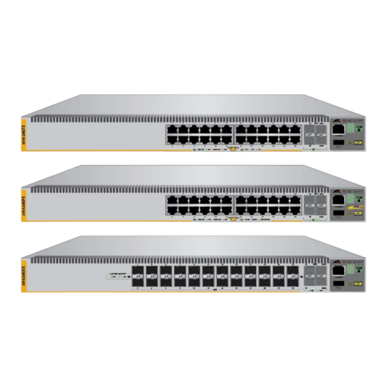
Page 19: Front And Back Panels
Series Installation Guide for Stand-alone Switches Front and Back Panels The front panels of the x510 Series switches are shown in Figure 1 and Figure 2 on page 20. AT-x510-28GTX 10/100/1000Base-T Ports Management Panel SFP+ Slots SFP+ or Stacking Slots... - Page 20 Chapter 1: Overview AT-x510-28GSX 10/100/1000Base-T and 100/1000Base-FX Management Transceiver Slots Panel SFP+ Slots SFP+ or Stacking Slots AT-x510-52GTX 10/100/1000Base-T Ports Management Panel SFP+ Slots SFP+ or Stacking Slots AT-x510-52GPX 10/100/1000Base-T Ports Management with PoE Panel SFP+ Slots SFP+ or Stacking Slots Figure 2.
Need help?
Do you have a question about the x510 Series and is the answer not in the manual?
Questions and answers