Allied Telesis x530 Series Quick Installation Manual
Hide thumbs
Also See for x530 Series:
- Installation manual (128 pages) ,
- Installation manual (200 pages)

Related Manuals for Allied Telesis x530 Series


Summary of Contents for Allied Telesis x530 Series
- Page 1 Series Stackable Multi-Gigabit Layer 3 Ethernet Switches AlliedWare Plus™ x530-28GTXm x530-28GPXm x530-52GTXm x530-52GPXm Quick Installation Guide *613-003075 Rev A* 613-003075 Rev. A...
-
Page 2: Table Of Contents
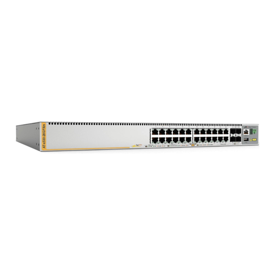
“Starting a Local Management Session” on page 21 “Disabling the VCStack Feature” on page 22 “Troubleshooting” on page 23 Front Panels Here are the front panels of the switches in the x530 Series. x530-28GTXm x530-28GPXm x530 Series Quick Installation Guide... - Page 3 1/10Gbps SFP+ transceiver ports Management panel Here are the 10/100/1000Mbps Ethernet copper ports. 10/100/1000Mbps 10/100/1000Mbps Switch Ports Ports with PoE+ x530-28GTXm 1 to 20 x530-28GPXm 1 to 20 x530-52GTXm 1 to 40 x530-52GPXm 1 to 40 x530 Series Quick Installation Guide...
- Page 4 1/10Gbps SFP+ Ports x530-28GTXm 25 to 28 x530-28GPXm 25 to 28 x530-52GTXm 49 to 52 x530-52GPXm 49 to 52 The management panel is shown here. Switch ID LED Console eco-friendly Management Button Port USB Port x530 Series Quick Installation Guide...
-
Page 5: Poe+ Power Budgets
In contrast, static port trunks in a stack can have ports from different switches. Note: For instructions, refer to the x530 Series Installation Guide for Virtual Chassis Stacking. x530 Series Quick Installation Guide... -
Page 6: Beginning The Installation
Note: The symbol indicates that a translation of the safety statement is available in the PDF document “Translated Safety Statements” on the Allied Telesis website at www.alliedtelesis.com/us/en/documents/translated-safety- statements. Warning: Class 1 Laser product. L1 Warning: Do not stare into the laser beam. L2 Warning: Power cord is used as a disconnection device. - Page 7 Unpacking the Switch Here are the accessory items that come with the switches. One 2m (6.6 ft) local management cable with RJ-45 (8P8C) and DB-9 (D-sub 9-pin) connectors. Two AC power cords Four bumper feet with rivets x530 Series Quick Installation Guide...
- Page 8 The power outlet should be located near the switch and be easily accessible. The site should allow for easy access to the ports on the front of the switch so that you can easily connect and disconnect cables, and view the port LEDs. x530 Series Quick Installation Guide...
-
Page 9: Installing The Switch
2. Inset a rivet housing into a bumper foot. 3. Place the bumper foot on one of the corner holes in the bottom panel of the switch. 4. Insert the rivet to secure the bumper foot to the base. x530 Series Quick Installation Guide... - Page 10 3. Attach two brackets to the sides of the switch with eight bracket screws included with the unit. The following figures illustrate the four possible positions of the brackets on the switch for a standard 19-inch equipment rack. x530 Series Quick Installation Guide...
- Page 11 Stud finder for a wooden wall, capable of identifying the middle of wall studs and hot electrical wiring (not provided) Drill and 1/4-inch carbide drill bit for a concrete wall (not provided) x530 Series Quick Installation Guide...
- Page 12 2. If the bumper feet are attached to the bottom of the switch, remove them using a flat-head screwdriver. 3. For the x530-28GTXm and x530-28GPXm Switches, attach two brackets with eight screws, as shown here. x530 Series Quick Installation Guide...
- Page 13 5. Have another person hold the switch on the wall at the selected location for the device while you use a pencil or pen to mark the wall with the locations of the screw holes in the brackets. x530 Series Quick Installation Guide...
-
Page 14: Ports
The connectors on the cables should fit snugly into the ports, and the tabs should lock the connectors into place. The default speed setting for the ports is Auto-Negotiation. This setting is appropriate for ports connected to network devices that also support Auto-Negotiation. x530 Series Quick Installation Guide... - Page 15 You can install SFP+ transceivers while the switch is powered on. For a list of supported transceivers, refer to the product’s data sheet on the Allied Telesis web site at www.alliedtelesis.com. The operational specifications and fiber optic cable requirements are included with the transceivers.
-
Page 16: Powering On The Switch
Warning: Power cord is used as a disconnection device. To de-energize equipment, disconnect the power cord. 1. Install the power cord retaining clip on the AC power connector on the rear panel of the switch, and raise the clip. x530 Series Quick Installation Guide... - Page 17 3. Plug the other end of the power cord into an appropriate AC power source. 4. Wait two minutes for the switch to initialize its management software. 5. Go to “LEDs” next or “Starting a Local Management Session” on page 21. x530 Series Quick Installation Guide...
-
Page 18: Leds
The port has established a link to another network Amber device, as follows: - For 10M/100M/1Gbps ports, the link is 10Mbps or 100Mbps. 100Mbps - For 100M/1/2.5/5Gbps ports, the link is Flashing The port is transmitting or receiving packets. Amber x530 Series Quick Installation Guide... - Page 19 - The port is disabled in the management software. - PoE+ is disabled on the port. - The LEDs are turned off. To turn on the LEDs, use the eco-friendly button. x530 Series Quick Installation Guide...
- Page 20 - The SFP+ transceiver port is empty. - The SFP+ transceiver has not established a link with another network device. - A non-supported module is installed. - The LEDs are turned off. To turn on the LEDs, use the eco-friendly button. x530 Series Quick Installation Guide...
-
Page 21: Starting A Local Management Session
See “Unpacking the Switch” on page 7. If your computer does not have a DB-9 connector, such as laptop computer, Allied Telesis offers the VT-Kit3 management cable for local management sessions. It has a USB-A male connector that connects to a USB port on your computer. -
Page 22: Disabling The Vcstack Feature
5. Wait two minutes for the switch to start the management software The switch in now in standalone mode. The SFP+ S1 and S2 ports are now regular Ethernet ports. 6. You can now cable the SFP+ S1 and S2 transceiver ports. x530 Series Quick Installation Guide... -
Page 23: Troubleshooting
Solutions: Try the following: Check the port’s PoE+ LED. Refer to “Ethernet Copper Port LEDs” on page 18. If the LED is flashing amber, the switch cannot support additional PoE+ devices device because it is x530 Series Quick Installation Guide... - Page 24 The information provided herein is subject to change without notice. In no event shall Allied Telesis, Inc. be liable for any incidental, special, indirect, or consequential damages whatsoever, including but not limited to lost profits, arising out of or related to this manual or the information contained herein, even if Allied Telesis, Inc.
Need help?
Do you have a question about the x530 Series and is the answer not in the manual?
Questions and answers