Allied Telesis x330-10GTX Installation Manual
Gigabit layer 3 ethernet switch
Hide thumbs
Also See for x330-10GTX:
- Installation manual (160 pages) ,
- Installation manual (126 pages) ,
- Installation manual (172 pages)
Table of Contents
Advertisement
Quick Links
Advertisement
Table of Contents

Related Manuals for Allied Telesis x330-10GTX


Summary of Contents for Allied Telesis x330-10GTX
- Page 1 Gigabit Layer 3 Ethernet Switch Installation Guide 613-002996 Rev. A...
- Page 2 Allied Telesis, Inc. has been advised of, known, or should have known, the...
- Page 3 Electrical Safety and Emissions Standards This product meets the following standards. U.S. Federal Communications Commission Radiated Energy Note: This equipment has been tested and found to comply with the limits for a Class A digital device pursuant to Part 15 of FCC Rules.
- Page 4 Table 1. Product Certifications (Continued) European Economic Area (EEA) (Conformité Européenne) WEEE (Waste Electrical and Electronic Equipment) RoHS (EU 1025/863) (Restriction of Hazardous Substances) European Standards (EN) EMC (Immunity): EN 55024, EN 55035 Laser Safety: EN 60825-1 EN 55032 Class A, EN 61000-3-2, EN 61000-3-3 India (Telecommunications Engineering Center) Japan...
- Page 5 Translated Safety Statements Important: Safety statements that have the symbol are translated into multiple languages in the Translated Safety Statements document at www.alliedtelesis.com/us/en/documents/translated- safety-statements. Remarque: Les consignes de sécurité portant le symbole sont traduites dans plusieurs langues dans le document Translated Safety Statements, disponible à l'adresse www.alliedtelesis.com/us/ en/documents/translated-safety-statements.
-
Page 7: Table Of Contents
Unpacking the Switch ................................44 Installation Options ................................45 Installing the Switch on a Table ............................46 Chapter 3: Installing the x330-10GTX Switch in an Equipment Rack ................. 49 Introduction ..................................50 Installing the x330-10GTX Switch............................53 Chapter 4: Installing the x330-10GTX Switch on a Wall ....................59 Introduction ..................................60... - Page 8 Contents Chapter 6: Cabling the Networking Ports ........................77 Cabling Copper Ports................................78 Guidelines to Handling SFP and SFP+ Transceivers ......................79 Installing 1Gbps SFP or 10Gbps SFP+ Transceiver ......................80 Installing an SP10TW Direct Connect Twinax Cable in the SFP+ Port ................83 Chapter 7: Troubleshooting ............................
- Page 9 Figure 12: Unsupported Table Installations ..........................46 Figure 13: Attaching the Bumper Feet..........................47 Figure 14: x330-10GTX Switch in an Equipment Rack with the RKMT-J05 Brackets Kit.............50 Figure 15: x330-10GTX Switch with RKMT-J05 Cable Trays....................51 Figure 16: Items in the RKMT-J05 Equipment Rack Brackets Kit ..................52 Figure 17: Placing the x330-10GTX Switch Upside Down on a Table .................53...
- Page 10 Figures...
- Page 11 Tables Table 1: Product Certifications ...............................3 Table 2: Features of the 10/100/1000Mbps Ethernet Copper Ports ..................22 Table 3: Features of the 1/2.5/5/10Gbps Ethernet Copper Port ..................24 Table 4: Link/Activity LEDs on the 10/100/1000Mbps Copper Ports ...................26 Table 5: Duplex Mode LEDs on the 10/100/1000Mbps Copper Ports .................27 Table 6: Link/Activity LEDs on the 1/2.5/5/10Gbps Copper Port ..................28 Table 7: Link/Activity LED for the 1/10Gbps SFP+ Port ......................29 Table 8: Product Dimensions ...............................90...
- Page 12 Tables...
-
Page 13: Preface
Preface This guide contains the installation instructions for the x330-10GTX Layer 3, Gigabit Ethernet switch. This preface contains the following sections: “Document Conventions” on page 14 “Contacting Allied Telesis” on page 15... -
Page 14: Document Conventions
Preface Document Conventions This document uses the following conventions: Note Notes provide additional information. Caution Cautions inform you that performing or omitting a specific action may result in equipment damage or loss of data. Warning Warnings inform you that performing or omitting a specific action may result in bodily injury. -
Page 15: Contacting Allied Telesis
Gigabit Ethernet Switch Installation Guide Contacting Allied Telesis For assistance with this product, you can contact Allied Telesis technical support from the Services & Support section of the Allied Telesis web site at www.alliedtelesis.com/us/en/services-support. The web page has links to the following services: ... - Page 16 Preface...
-
Page 17: Chapter 1: Overview
Chapter 1 Overview This chapter contains the following sections: “Front and Back Panels” on page 18 “Features” on page 19 “10/100/1000Mbps Ethernet Copper Ports” on page 22 “1/2.5/5/10Gbps Ethernet Copper Port” on page 24 “SFP+ Port” on page 25 ... -
Page 18: Front And Back Panels
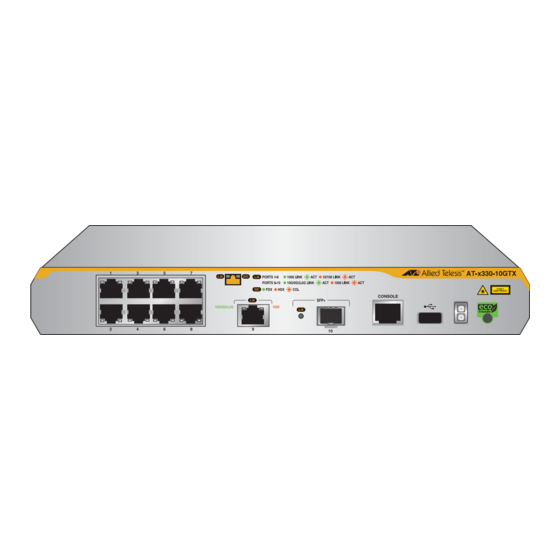
Chapter 1: Overview Front and Back Panels Figure 1 illustrates the front panel of the x330-10GTX switch. E. One USB Flash Drive A. Eight 10/100/1000Mbps Port Ethernet Copper Ports F. Switch ID LED B. One 1/2.5/5/10Gbps Ethernet Copper Port G. eco-friendly Button C. -
Page 19: Features
Gigabit Ethernet Switch Installation Guide Features 10/100/1000Mbps The 10/100/1000Mbps Ethernet copper ports have these basic features: Ethernet Copper 10Base-T, 100Base-TX, and 1000Base-T compliant Ports IEEE 802.3u Auto-Negotiation compliant Auto-MDI/MDIX 100 meters (328 feet) maximum operating distance ... -
Page 20: Leds
Chapter 1: Overview Note The port supports full-duplex mode only. Note SFP and SFP+ transceivers are sold separately. Refer to the product’s data sheet on the Allied Telesis website for a list of supported transceivers. LEDs Here are the port LEDs: ... -
Page 21: Management Methods
Gigabit Ethernet Switch Installation Guide Management Here are the methods for managing the switches: Methods Local management through the Console port Remote Telnet and Secure Shell management Remote HTTP and HTTPS web browser management SNMPv1, v2c, and v3... -
Page 22: 10/100/1000Mbps Ethernet Copper Ports
Chapter 1: Overview 10/100/1000Mbps Ethernet Copper Ports Table 1 lists the features of the 10/100/1000Mbps copper ports. Table 1. Features of the 10/100/1000Mbps Ethernet Copper Ports Feature Description Speeds Port speeds are listed here: - 10Mbps (IEEE802.3 10Base-T) - 100Mbps (IEEE802.3u 100Base-TX) - 1Gbps (IEEE802.3ab 1000Base-T) Speeds are set manually or with IEEE 802.3u Auto-Negotiation. - Page 23 Gigabit Ethernet Switch Installation Guide Table 1. Features of the 10/100/1000Mbps Ethernet Copper Ports Feature Description Additional Features Additional features are listed here: - 8-pin RJ-45 connectors - Backpressure flow control supported at half- duplex mode - Non-blocking, wire speed supported at all speeds.
-
Page 24: 1/2.5/5/10Gbps Ethernet Copper Port
Chapter 1: Overview 1/2.5/5/10Gbps Ethernet Copper Port The specifications of the 1/2.5/5/10Gbps copper port are listed in Table 2. Table 2. Features of the 1/2.5/5/10Gbps Ethernet Copper Port Specification Description Port Speed Here are the supported speeds: - 1Gbps (IEEE802.3ab) - 2.5Gbps (IEEE 802.3bz) - 5Gbps (IEEE 802.3bz) - 10Gbps (IEEE 802.3an) -
Page 25: Sfp+ Port
Gigabit Ethernet Switch Installation Guide SFP+ Port The SFP+ port on the switch supports the following types of SFP 1000Mbps and SFP+ 10Gbps transceivers: 1Gbps 1000Base-SX/LX SFP transceivers 1Gbps single-port BiDi 1000Base-LX SFP transceivers 1Gbps 1000Base-ZX SFP transceivers ... -
Page 26: Port Leds
Chapter 1: Overview Port LEDs This section explains the copper and SFP+ port LEDs. 10/100/1000Mbps The 10/100/1000Mbps Ethernet copper ports have two LEDs that display the following: Ethernet Copper Link/activity Port LEDs Duplex mode The LEDs are identified in Figure 3. Duplex mode LED Link/activity LED Duplex mode LED... -
Page 27: 1/2.5/5/10Gbps Ethernet Copper Port Leds
Gigabit Ethernet Switch Installation Guide Table 3. Link/Activity LEDs on the 10/100/1000Mbps Copper Ports State Description Possible causes of this state are listed here: - The port has not established a link with another network device. - The LEDs are turned off. To turn on the LEDs, use the eco-friendly button. -
Page 28: 1/10Gbps Sfp+ Port Led
Chapter 1: Overview Table 5 describes the LEDs. Table 5. Link/Activity LEDs on the 1/2.5/5/10Gbps Copper Port State Description Solid Green The port has established a 2.5Gbps, 5Gbps, or 10Gbps link to a network device. Flashing Green The port is transmitting or receiving data at 2.5Gbps, 5Gbps, or 10Gbps. - Page 29 Gigabit Ethernet Switch Installation Guide Table 6 describes the LED. Table 6. Link/Activity LED for the 1/10Gbps SFP+ Port State Description Solid Amber The port has established a 1Gbps link to a network device. Flashing Amber The port is transmitting or receiving data at 1Gbps.
-
Page 30: Eco-Friendly Button
VCStack, as detailed in Figure 8 on page 32. Note The x330-10GTX switch does not support the VCStack feature. It supports the standalone mode only. Note Before checking or troubleshooting the network connections to the... -
Page 31: Switch Id Led
Switch ID LED The Switch ID LED, shown in Figure 6, is for the VCStack feature, which allows multiple switches to function as a single unit. The x330-10GTX switch does not support the VCStack feature. It operates as a standalone device with a Switch ID of “0”. -
Page 32: Figure 8: Switch Id Led With Low Power Mode Enabled
The states of the LED when low power mode is enabled are shown in Figure 8. The switch is the master switch of a VCStack. (The x330-10GTX switch does not support stacking.) The switch is a standalone unit. The switch is a member switch of a VCStack. -
Page 33: Usb Port
Gigabit Ethernet Switch Installation Guide USB Port The management panel has a USB port. You can use the port to store configuration files on flash drives or to restore configuration files to the switch if its settings are lost or corrupted, or to quickly configure replacement units. -
Page 34: Console Port
Chapter 1: Overview Console Port You use the Console port to manage the features and parameter settings with the command line interface provided with the switch. This type of management is referred to as local management. It is not conducted over your network. -
Page 35: Power Supply
Gigabit Ethernet Switch Installation Guide Power Supply The switch has one internal power supply. The power supply is not field- replaceable. Refer to “Power Specifications” on page 93 for the input voltage ranges. The switch supports IEEE 802.3az Energy-Efficient Ethernet (EEE). EEE is an energy saving feature that reduces power consumption during periods of no data activity. - Page 36 Chapter 1: Overview...
-
Page 37: Chapter 2: Beginning The Installation
Chapter 2 Beginning the Installation The chapter contains the following sections: “Reviewing Safety Precautions” on page 38 “Choosing a Site for the Switch” on page 42 “Unpacking the Switch” on page 44 “Installation Options” on page 45 ... -
Page 38: Reviewing Safety Precautions
Chapter 2: Beginning the Installation Reviewing Safety Precautions Review the following safety precautions before beginning the installation procedure. Note Safety statements that have the symbol are translated into multiple languages in the Translated Safety Statements document at www.alliedtelesis.com/en/documents/translated-safety- statements. Note Les consignes de sécurité... - Page 39 Gigabit Ethernet Switch Installation Guide Warning Power cord is used as a disconnection device. To de-energize equipment, disconnect the power cord. Warning Class I Equipment. This equipment must be earthed. The power plug must be connected to a properly wired earth ground socket outlet.
- Page 40 Use dedicated power circuits or power conditioners to supply reliable electrical power to the device. Caution The chassis may be heavy and awkward to lift. Allied Telesis recommends that you get assistance when mounting the chassis in an equipment rack. ...
- Page 41 Gigabit Ethernet Switch Installation Guide Caution The unit does not contain serviceable components. Please return damaged units for servicing. Warning The temperature of an active SFP transceiver may exceed 40° C (158° F). Exercise caution when handling with unprotected hands.
-
Page 42: Choosing A Site For The Switch
LEDs. The x330-10GTX switch does not have cooling fans. The site must provide adequate air flow around the unit for cooling. Do not install the switch in a wiring or utility box without adequate airflow. -
Page 43: Enclosure Requirements
If the product overheats in an enclosure that was built without taking into account these factors, the warranty of the product might be voided. Consult Allied Telesis when assistance is needed. The enclosure’s BTU/hour rating must be higher than the total BTU/hour values of equipment installed in the enclosure, over the expected operating temperature range. -
Page 44: Unpacking The Switch
Chapter 2: Beginning the Installation Unpacking the Switch Figure 9 lists the accessory items that come with the x330-10GTX switch. Management cable, with RJ- 45 (8P8C) and DB-9 (D-sub 9- pin) connectors. AC power cord Power cord retainer clip Four bumper feet Four 3x4.5mm screws... -
Page 45: Installation Options
Gigabit Ethernet Switch Installation Guide Installation Options Figure 10 illustrates the installation options for the x330-10GTX switch. Table or desktop with the bumper feet shipped with the switch. Standard 19-inch equipment rack with RKMT-J05 rack-mount brackets. Brackets sold separately. -
Page 46: Installing The Switch On A Table
Chapter 2: Beginning the Installation Installing the Switch on a Table You can operate the switch on a table or desktop. Refer to Figure 11. Figure 11. Switch Installation on a Table The following guidelines are in addition to those in “Choosing a Site for the Switch”... -
Page 47: Figure 13: Attaching The Bumper Feet
Gigabit Ethernet Switch Installation Guide Perform the following procedure to install the switch on a table: 1. Review “Reviewing Safety Precautions” on page 38 and “Choosing a Site for the Switch” on page 42 to verify that the selected site is suitable for the unit. - Page 48 Chapter 2: Beginning the Installation...
-
Page 49: Chapter 3: Installing The X330-10Gtx Switch In An Equipment Rack
Chapter 3 Installing the x330-10GTX Switch in an Equipment Rack The instructions in this chapter explain how to install the x330-10GTX switch in a standard 19-inch equipment rack with the optional RKMT-J05 equipment rack brackets kit. Here are the sections: ... -
Page 50: Introduction
Refer to Figure 14. Figure 14. x330-10GTX Switch in an Equipment Rack with the RKMT-J05 Brackets Kit... -
Page 51: Figure 15: X330-10Gtx Switch With Rkmt-J05 Cable Trays
The RKMT-J05 bracket kit includes two cable trays and ten tie wraps for physically securing the power cord or network cables. Refer to Figure 15. Figure 15. x330-10GTX Switch with RKMT-J05 Cable Trays Note The RKMT-J05 equipment rack brackets kit is sold separately. -
Page 52: Figure 16: Items In The Rkmt-J05 Equipment Rack Brackets Kit
Chapter 3: Installing the x330-10GTX Switch in an Equipment Rack Figure 16 illustrates the items in the RKMT-J05 brackets kit. Two handles Two short brackets Two long brackets Two cable trays Eight M3x6mm truss Eight M4x6mm truss head screws head screws Ten Tie Wraps Figure 16. -
Page 53: Installing The X330-10Gtx Switch
To install the switch in a 19-inch equipment rack with the RKMT-J05 equipment rack brackets kit, perform the following procedure: 1. Place the x330-10GTX switch upside down on a table or desk. Refer to Figure 17. Figure 17. Placing the x330-10GTX Switch Upside Down on a Table... -
Page 54: Figure 18: Removing The Feet From The X330-10Gtx Switch
Chapter 3: Installing the x330-10GTX Switch in an Equipment Rack 2. Remove the four bumper feet from the bottom panel of the switch with a Phillips-head screwdriver. Refer to Figure 18. Figure 18. Removing the Feet from the x330-10GTX Switch 3. -
Page 55: Figure 20: Attaching The Short Rkmt-J05 Brackets To The Long Brackets
Gigabit Ethernet Switch Installation Guide 4. Attach the short brackets to the long brackets using the supplied M4x6mm counter sunk screws. Refer to Figure 20. Figure 20. Attaching the Short RKMT-J05 Brackets to the Long Brackets... -
Page 56: Figure 21: Attaching The Rkmt-J05 Cord Trays To The Long Brackets
Chapter 3: Installing the x330-10GTX Switch in an Equipment Rack 5. Attach one or both cord trays to the long brackets. The cord trays are optional. Refer to Figure 21. Figure 21. Attaching the RKMT-J05 Cord Trays to the Long Brackets... -
Page 57: Figure 22: Attaching The Rkmt-J05 Brackets To The Switch
Gigabit Ethernet Switch Installation Guide 6. Attach the brackets to the bottom panel of the switch. Refer to Figure 22. Figure 22. Attaching the RKMT-J05 Brackets to the Switch 7. Turn the switch right-side up on the table. -
Page 58: Figure 23: Attaching The X330-10Gtx Switch To An Equipment Rack
Chapter 3: Installing the x330-10GTX Switch in an Equipment Rack 8. Have another person hold the switch in the equipment rack while you secure it with four standard equipment rack screws (not provided). Refer to Figure 23. Figure 23. Attaching the x330-10GTX Switch to an Equipment Rack... - Page 59 Chapter 4 Installing the x330-10GTX Switch on a Wall The procedures in this chapter are listed here: “Introduction” on page 60 “Installation Guidelines” on page 62 “Tools and Material” on page 63 “Installing the Switch” on page 64...
-
Page 60: Chapter 4: Installing The X330-10Gtx Switch On A Wall
Chapter 4: Installing the x330-10GTX Switch on a Wall Introduction Installing the x330-10GTX switch on a wall requires the BRKT-J23 bracket kit. The kit contains two identical brackets. Refer to Figure 24. Figure 24. BRKT-J23 Bracket Kit Note The BRKT-J23 bracket kit is sold separately. -
Page 61: Figure 26: X330-10Gtx Switch Wall Installations With Four Brkt-J23 Brackets
Gigabit Ethernet Switch Installation Guide Figure 26 shows the switch with four brackets. Figure 26. x330-10GTX Switch Wall Installations with Four BRKT-J23 Brackets Do not install the switch with the front panel facing down. Refer to Figure 27. Figure 27. Invalid Wall Installation with Front Panel Facing Down... -
Page 62: Installation Guidelines
Chapter 4: Installing the x330-10GTX Switch on a Wall Installation Guidelines Here are the guidelines to installing the switch on a wall: As shown in Figure 25 on page 60 and Figure 26 on page 61, the BRKT-J23 brackets secure the device by its sides. Installing the brackets over the front or rear panel will block copper ports or the AC power connector. -
Page 63: Tools And Material
Gigabit Ethernet Switch Installation Guide Tools and Material Here are the required tools and material for installing the switch on a wooden or concrete wall with the BRKT-J23 brackets: One or two BRKT-J23 bracket kits Four or eight wall screws (not provided) ... -
Page 64: Installing The Switch
1 and 2 to remove them. Otherwise, start with step 3. Perform the following procedure to install the switch on a wall: 1. Place the x330-10GTX switch upside down on a table or desk. Refer to Figure 17 on page 53. -
Page 65: Figure 28: Marking The Screw Holes For Two Brkt-J23 Brackets
Gigabit Ethernet Switch Installation Guide Figure 28. Marking the Screw Holes for Two BRKT-J23 Brackets Figure 29. Marking the Screw Holes for Four BRKT-J23 Brackets... -
Page 66: Figure 30: Attaching The Bottom Brkt-J23 Brackets To The Wall
Chapter 4: Installing the x330-10GTX Switch on a Wall 5. Place the switch and brackets on a table. 6. For a wooden wall, use a stud-finder to determine if there are any live electrical wires at the screw hole locations. -
Page 67: Figure 31: Sliding The Switch Into The Brkt-J23 Brackets
Gigabit Ethernet Switch Installation Guide 10. Slide the switch into the BRKT-J23 brackets. Refer to Figure 31. Figure 31. Sliding the Switch into the BRKT-J23 Brackets Note If you are installing the switch with two brackets, skip the next step and go to Chapter 5, “Verifying the Switch”... -
Page 68: Figure 32: Attaching The Top Brkt-J23 Brackets To The Wall
Chapter 4: Installing the x330-10GTX Switch on a Wall 11. Attach the two top brackets to the wall with appropriate screws. Refer to Figure 32. Figure 32. Attaching the Top BRKT-J23 Brackets to the Wall 12. Go to Chapter 5, “Verifying the Switch” on page 69. -
Page 69: Chapter 5: Verifying The Switch
Chapter 5 Verifying the Switch This chapter contains the following procedures: “Powering On the Switch” on page 70 “Starting a Local Management Session” on page 73 “Verifying the Switch” on page 76... -
Page 70: Powering On The Switch
Chapter 5: Verifying the Switch Powering On the Switch The procedure in this section explains how to power on the switch. Before powering on the device, review the information in “Power Specifications” on page 93. Warning Power cord is used as a disconnection device. To de-energize equipment, disconnect the power cord. -
Page 71: Figure 34: Connecting The Ac Power Cord
Gigabit Ethernet Switch Installation Guide Figure 34. Connecting the AC Power Cord 3. Lower the power cord retaining clip to secure the cord to the switch. Refer to Figure 35. Figure 35. Lowering the Power Cord Retaining Clip 4. Connect the power cord to an appropriate AC power source. Refer to Figure 36. - Page 72 Chapter 5: Verifying the Switch Note The illustration shows a North American power cord. Your power cord may be different. 5. Wait two minutes for the switch to initialize the management software. 6. To verify hardware operations, begin with “Starting a Local Management Session”...
-
Page 73: Starting A Local Management Session
IPv4 address 169.254.42.42/16. Local management sessions of the switch require a management cable. There are two available cables from Allied Telesis. One cable comes with the switch. It has an RJ-45 (8P8C) connector that connects to the Console port on the switch and a DB-9 (D-sub 9-pin) connector that connects to your workstation. -
Page 74: Figure 39: Management Workstation, Vt-Kit3 Management Cable, And Switch
To use the cable, you connect it to the Console port on the switch with a standard, straight-through Ethernet cable. Refer to Figure 39. The cable requires a software driver from Allied Telesis. The VT-Kit3 management cable is sold separately. -
Page 75: Figure 41: User Exec Mode Prompt
Gigabit Ethernet Switch Installation Guide 2. Connect the other end of the cable to an RS-232 port on a terminal or personal computer with a terminal emulation program. 3. Configure the VT-100 terminal or terminal emulation program as follows: ... -
Page 76: Verifying The Switch
4. Check the Status column. All components should have the “OK” status. For information about the command line interface, refer to the Software Reference for x330 Series Switches, AlliedWare Plus Operating System on the Allied Telesis web site. 5. Go to Chapter 6, “Cabling the Networking Ports” on page 77. -
Page 77: Chapter 6: Cabling The Networking Ports
Chapter 6 Cabling the Networking Ports This chapter contains the following sections: “Cabling Copper Ports” on page 78 “Guidelines to Handling SFP and SFP+ Transceivers” on page 79 “Installing 1Gbps SFP or 10Gbps SFP+ Transceiver” on page 80 ... -
Page 78: Cabling Copper Ports
Chapter 6: Cabling the Networking Ports Cabling Copper Ports Here are the guidelines to cabling the copper ports: The cable specifications are in “10/100/1000Mbps Ethernet Copper Ports” on page 22 and “1/2.5/5/10Gbps Ethernet Copper Port” on page 24. The connectors on the cables should fit snugly into the ports, and the tabs should lock the connectors into place. -
Page 79: Guidelines To Handling Sfp And Sfp+ Transceivers
Gigabit Ethernet Switch Installation Guide Guidelines to Handling SFP and SFP+ Transceivers Please review the following guidelines before installing SFP or SFP+ transceivers in the switches: Transceivers are hot-swappable. You can install them while the switch is powered on. -
Page 80: Installing 1Gbps Sfp Or 10Gbps Sfp+ Transceiver
To install transceivers, perform the following procedure: 1. Remove the transceiver from its shipping container and store the packaging material in a safe location. 2. Position the transceiver with the Allied Telesis label facing up. Refer to Figure 43. Figure 43. Installing an SFP+ Transceiver 3. -
Page 81: Figure 44: Removing The Dust Cover From An Sfp+ Transceiver
Gigabit Ethernet Switch Installation Guide 4. Remove the dust cover from the transceiver, as shown in Figure 44. Figure 44. Removing the Dust Cover from an SFP+ Transceiver 5. Verify the position of the handle on the transceiver. The handle should be in the upright position, as shown in Figure 45. -
Page 82: Figure 46: Connecting A Fiber Optic Cable To An Sfp Or Sfp+ Transceiver
Chapter 6: Cabling the Networking Ports Figure 46. Connecting a Fiber Optic Cable to an SFP or SFP+ Transceiver... -
Page 83: Installing An Sp10Tw Direct Connect Twinax Cable In The Sfp+ Port
To install an SP10TW cable, perform the following procedure: 1. Remove the transceiver from its shipping container and store the packaging material in a safe location. 2. Position the transceiver with the Allied Telesis label facing up. Refer to Figure 47. Figure 47. Installing an SP10TW Cable... - Page 84 Chapter 6: Cabling the Networking Ports 3. Slide the transceiver into the port until it clicks into place. 4. Connect the other end of the cable into an SFP+ port on another network device. Note To remove the connector and cable from the port, gently push on the connector, pull on the release tab, and slide the connector from the switch.
-
Page 85: Chapter 7: Troubleshooting
This chapter contains suggestions on how to troubleshoot problems with the switch. Note For further assistance, please contact Allied Telesis Technical Support at www.alliedtelesis.com/us/en/services-support. Problem 1: The ports are connected to network devices but the LEDs and Switch ID LED are off. - Page 86 (sensitivity) or too strong (maximum input power). Verify that the x330-10GTX switch supports the transceiver by referring to its data sheet. Problem 4: The switch functions intermittently.
- Page 87 Gigabit Ethernet Switch Installation Guide power source to the switch is stable and within the approved operating range. The unit will shut down if the input voltage fluctuates above or below the approved operating range. Verify that the location of the switch allows for adequate airflow.
- Page 88 Chapter 7: Troubleshooting...
-
Page 89: Appendix A: Technical Specifications
Appendix A Technical Specifications This appendix contains the following sections: ”Physical Specifications” on page 90 ”Environmental Specifications” on page 92 ”Power Specifications” on page 93 ”Certifications” on page 94 ”RJ-45 Copper Port Pinouts” on page 96 ... -
Page 90: Physical Specifications
Table 7 lists the dimensions of the switch. Table 7. Product Dimensions x330-10GTX 263 x 179 x 38 mm (10.35 x 7.04 x 1.497.0 in.) Width 263 mm (10.35 in.) Height 38 mm (1.497 in.) Depth 179 mm (7.04 in.) Figure 48. x330-10GTX Switch Dimensions... - Page 91 Gigabit Ethernet Switch Installation Guide Weight Table 8 lists the weight of the switch. Table 8. Product Weight x330-10GTX Unpackaged: 1.6 kg (3.53 lb.) Packaged: 2.97 kg (6.55 lb) Ventilation Table 9 lists the ventilation requirements. Table 9. Ventilation Requirements Recommended Minimum 10 cm (4.0 in)
-
Page 92: Environmental Specifications
Appendix A: Technical Specifications Environmental Specifications Table 10 lists the environmental specifications of the switches. Table 10. Environmental Specifications Operating Temperature Range 0° C to 50° C (32° F to 122° F) Storage Temperature -25° C to 70° C (-13° F to 158° F) Operating Humidity 5% to 90% noncondensing Storage Humidity... -
Page 93: Power Specifications
Gigabit Ethernet Switch Installation Guide Power Specifications This section contains the maximum power consumption, input voltage, and heat dissipation. Maximum Power Consumption Table 11 lists the maximum power consumption of the switch. Table 11. Maximum Power Consumption x330-10GTX 19 watts Input Voltage Table 12 lists the input voltage for the switch. -
Page 94: Certifications
Appendix A: Technical Specifications Certifications Table 14 lists the product certificates. Table 14. Product Certifications Additional Certificates CISPR Class A é é (Comit International Sp cial des é Perturbations Radio lectriques) Compliant with European and China RoHS standards Australia/New Zealand (Regulatory Compliance Mark) Common Criteria NIAP... - Page 95 Gigabit Ethernet Switch Installation Guide Table 14. Product Certifications (Continued) Mexico (Normas Oficiales Mexicanas) North America FCC Class A Laser Safety: EN 60825-1 Energy Star Russia (Eurasian Conformity) United Kingdom UKCA (UK Conformity Assessment)
-
Page 96: Copper Port Pinouts
Appendix A: Technical Specifications RJ-45 Copper Port Pinouts Figure 49 illustrates the pin layout of the RJ-45 copper ports. Figure 49. Pin Layout for the RJ-45 Copper Ports (Front View) Table 15 lists the pin signals for the copper ports. Table 15. -
Page 97: Style Serial Console Port Pinouts
Gigabit Ethernet Switch Installation Guide RJ-45 Style Serial Console Port Pinouts Table 16 lists the pin signals of the RJ-45 style serial Console port. Table 16. RJ-45 Style Serial Console Port Pin Signals Signal Unused Unused Transmit Data Signal Ground... - Page 98 Appendix A: Technical Specifications...
Need help?
Do you have a question about the x330-10GTX and is the answer not in the manual?
Questions and answers