Sign In
Upload
Manuals
Brands
Siemens Manuals
Control Unit
SINAMICS DCM
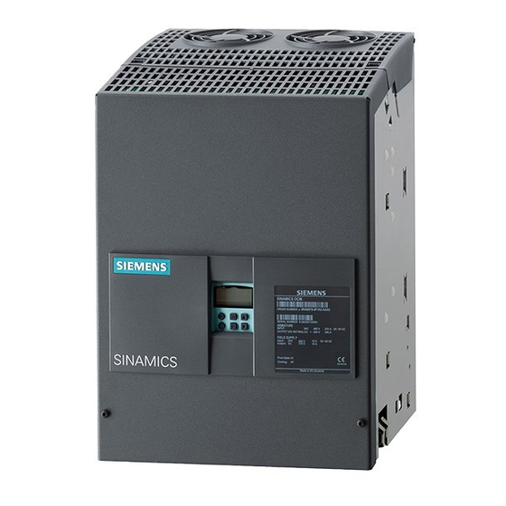
Siemens SINAMICS DCM Manuals
Manuals and User Guides for Siemens SINAMICS DCM. We have
11
Siemens SINAMICS DCM manuals available for free PDF download: List Manual, Operating Instructions Manual, Manual, User Manual, Compact User Manual, Hardware Installation Manual
Siemens SINAMICS DCM List Manual (1205 pages)
Brand:
Siemens
| Category:
Control Unit
| Size: 6.52 MB
Table of Contents
Function Diagrams
3
Proper Use of Siemens Products
4
Qualified Personnel
4
Warning Notice System
4
Information about the SINAMICS Documentation
5
Technical Support
6
Table of Contents
7
Fundamental Safety Instructions
9
General Safety Instructions
10
Parameters
10
Industrial Security
11
Parameters
13
Basic Structure of the Parameter Descriptions
14
Explanation of the List of Parameters
14
Overview of Parameters
14
Parameter Number
15
Drive Object (Function Module)
16
Faults and Alarms
16
Full Parameter Name / Abbreviated Parameter Name
16
Data in the "Drive Object (Function Module)" Field
17
Can be Changed
18
Access Level
19
Calculated
19
Data Type
20
Possible Combinations of BICO Interconnections
20
Dynamic Index
21
Function Diagram
21
Unit, Unit Group and Unit Selection
21
Expert List
22
Not for Motor Type
22
Parameter Values
22
Scaling
22
Safety Instructions
24
Number Ranges for SINAMICS in General
25
Number Ranges of Parameters
25
Control Unit Operating Display / CU Op_Display
28
Drive Operating Display / Drv Op_Display
28
List of Parameters
28
TM150 Operating Display / TM150 Op_Display
30
TM15DI/DO Operating Display / TM15D Op_Display
30
TM31 Operating Display / TM31 Op_Display
30
BOP Access Level / BOP Acc_Level
31
BOP Operating Display Mode / BOP Op_ Disp Mode
33
BOP Operating Display Selection / BOP Op_Disp Sel
33
BOP Background Lighting / BOP Lighting
34
BOP Drive Object after Booting / BOP DO after Boot
34
Device Commissioning Parameter Filter / Dev Comm Par_Filt
34
Drive Commissioning Parameter Filter / Drv Comm. Par_Filt
35
TM150 Commissioning Parameter Filter / TM150 Com Par_Filt
35
BOP Password Entry (P0013) / BOP Passw Ent P13
36
TM15DI/DO Commissioning the Parameterizing Filter / TM15D Com Par_Filt
36
TM31 Commissioning Parameter Filter / TM31 Comm Par_Filt
36
BOP Password Acknowledgement (P0013) / BOP Passw Ackn P13
37
BOP User-Defined List / BOP List
37
Macro Drive Unit / Macro Drv Unit
37
Activate BOP User-Defined List / BOP User List Act
38
Control Unit Basic Firmware Version / CU Basic FW Vers
38
Macro Drive Object / Macro DO
38
CO/BO: Control Word BOP / STW BOP
39
CO: Actual Speed Smoothed / N_Act Smooth
39
Speed Actual Value Rpm Smoothed / N_Act Rpm Smooth
39
Speed Setpoint Smoothed / N_Set Smth
39
Actual Torque Smoothed / M_Act Smooth
40
CO: Absolute Actual Current Smoothed / I_Act Abs Val Smth
40
CO: Active Power Actual Value Smoothed / P_Actv_Act Smth
40
CO/BO: Missing Enable Sig / Missing Enable Sig
41
CO: Motor Temperature / Mot Temp
41
Display Values Smoothing Time Constant / Disp_Val T_Smooth
41
CO/BO: Command Data Set CDS Effective / CDS Effective
42
CO/BO: Drive Data Set DDS Effective / DDS Effective
42
Encoder Data Set Effective / EDS Effective
42
CO/BO: Status Word, Closed-Loop Control / ZSW Cl-Loop Ctrl
43
CO: Actual Speed Unsmoothed / N_Act Unsmoothed
43
CO: Speed Actual Value / N_Act
43
CO: Speed Setpoint before the Setpoint Filter / N_Set before Filt.
43
CO: Absolute Current Actual Value / I_Act Abs Val
44
CO: Active Power Actual Value / P_Act
44
CO: Torque Actual Value / M_Act
44
Select Drive Object Type / Select DO Type
44
Actual Device Topology / Device_Act Topo
45
Device Target Topology / Device_Target Topo
45
Application-Specific View / Appl_Spec View
46
Drive Object Numbers / DO Numbers
46
Number of Drive Objects / DO Count
46
Activate/De-Activate Drive Object / DO Act/Deact
47
Drive Object Active/Inactive / DO Act/Inact
49
Drive Object Type / DO Type
49
Drive Objects Function Module / DO Fct_Mod
51
Basic Sampling Time Selection / T_Basis Sel
53
Sampling Time for Supplementary Functions / T_Samp Suppl_Fct
53
Sampling Times for Internal Control Loops / T_Sample Int Ctrl
53
Sampling Times Pre-Setting P0115 / T_Sample for P0115
53
Drive Object Clock Cycle Recommended / Do_Clock Recom
54
Activate/De-Activate Power Unit Components / Pu_Comp Act/Deact
55
Main Component Detection Using LED / M_Comp Detect LED
55
Power Unit Component Number / PU Comp_No
55
Encoder Interface (Sensor Module) Component Number
56
Number of Encoder Data Sets (EDS) / EDS Count
56
Sensor Module Detection Via LED / SM Detection LED
56
Activate/De-Activate Encoder Interface / Enc_Intf Act/Deact
57
Encoder Interface Active/Inactive / Enc_Intf Act/Inact
57
Sensor Module EEPROM Data Version / SM EEPROM Version
57
Sensor Module Firmware Version / SM FW Version
58
Terminal Module Component Number / TM Comp_No
58
Terminal Module Detection Via LED / TM Detection LED
58
Terminal Module EEPROM Data Version / TM EEPROM Version
58
Encoder 1 Encoder Data Set Number / Enc 1 EDS Number
59
Number of Command Data Sets (CDS) / CDS Count
59
Number of Drive Data Sets (DDS) / DDS Count
59
Terminal Module Firmware Version / TM FW Version
59
Encoder 2 Encoder Data Set Number / Enc 2 EDS Number
60
Topology Component Status / Top Comp Stat
60
BIOS/EEPROM Data Version / BIOS/EEPROM Vers
61
Bootloader Version / Bootloader Vers
61
Drive Object Name / DO Name
61
Automatic Calculation Motor/Control Parameters / Calc Auto Par
62
Firmware Package Name / FW Pkg Name
62
Power Unit Code Number / PU Code no
62
Power Unit Code Number Actual / PU Code No. Act
62
Encoder Type OEM Selection / Enc Type OEM Sel
63
Encoder Type Selection / Enc_Typ Sel
63
Encoder Configuration Effective / Enc_Config Eff
64
Gearbox Type Selection / Gearbox Type Sel
64
Square-Wave Encoder Track A/B / Sq-Wave Enc A/B
65
Encoder Inversion Actual Value / Enc Inv Act Value
66
Linear Encoder Grid Division / Enc Grid DIV
66
Rotary Encoder Pulse Number / Rot Enc Pulse No.
66
Measuring Gear Absolute Encoder Rotary Revolutions Virtual
67
Measuring Gear Configuration / Meas Gear Config
67
Gx_Xist1 Coarse Position Safe most Significant Bit (Identified)
68
Measuring Gear Position Tracking Tolerance Window / Pos Track Window
68
Non Safety-Relevant Meas. Steps Position Value POS1 (Detected)
68
Redundant Coarse Position Value Relevant Bits (Identified)
68
Encoder Connection / Enc_Connection
69
Encoder Safety Comparison Algorithm (Detected) / Safety Comp_Algo
69
Fine Resolution Absolute Value Gx_Xist2 (in Bits) / Enc Fine Gx_Xist2
69
Fine Resolution Gx_Xist1 (in Bits) / Enc Fine Gx_Xist1
69
Absolute Encoder Linear Measuring Step Resolution / Enc Abs Meas Step
70
Absolute Encoder Rotary Multiturn Resolution / Enc Abs Multiturn
70
Absolute Encoder Rotary Singleturn Resolution / Enc Abs Singleturn
70
Encoder Linear Zero Mark Distance / Enc Lin Zm_Dist
70
Encoder Rotary Zero Mark Distance / Enc Rot Dist ZM
71
Encoder SSI Baud Rate / Enc SSI Baud Rate
71
Encoder SSI Monoflop Time / Enc SSI T_Monoflop
71
Encoder Zero Mark Differential Distance / Enc ZM Dif_Dist
71
Encoder SSI Configuration / Enc SSI Config
72
Sensor Module Configuration / SM Config
72
Angular Commutation Offset / Ang_Com Offset
73
Gearbox Factor Encoder Revolutions / Grbx_Fact Enc_Rev
73
Encoder SSI Error Bit / Enc SSI Error Bit
74
Gearbox Factor Motor/Load Revolutions / Grbx_Fact Mot_Rev
74
Encoder SSI Parity Bit / Enc SSI Parity Bit
75
Sensor Module Configuration Extended / SM Config Ext
75
Squarewave Encoder Filter Time / Enc T_Filt
76
Copy Encoder Serial Number / Copy Enc Ser_No
77
Encoder Commissioning Serial Number Part 1 / Enc Comm Ser_No 1
77
Encoder Ramp-Up Time / Enc Ramp-Up Time
77
Encoder Commissioning Serial Number Part 2 / Enc Comm Ser_No 2
78
Encoder Commissioning Serial Number Part 3 / Enc Comm Ser_No 3
78
Encoder Commissioning Serial Number Part 4 / Enc Comm Ser_No 4
78
Encoder Commissioning Serial Number Part 5 / Enc Comm Ser_No 5
78
Encoder Configuration Recognized / Enc Config Act
79
Pulse Encoder Evaluation Zero Speed Measuring Time / Enc_Ev N_0 T_Meas
79
Squarewave Encoder Filter Time Display / Enc T_Filt Displ
79
Encoder Configuration Supported / Enc_Config Supp
80
Sensor Module Properties / SM Properties
80
Encoder Serial Number Part 1 / Enc Ser_No 1
82
Sensor Module Properties Extended / SM Prop Ext
82
Encoder Serial Number Part 2 / Enc Ser_No 2
83
Encoder Serial Number Part 3 / Enc Ser_No 3
83
Encoder Serial Number Part 4 / Enc Ser_No 4
83
Encoder Serial Number Part 5 / Enc Ser_No 5
83
Absolute Encoder Linear Measuring Step / Enc Lin Meas Step
84
Encoder 1 Identification Number/Serial Number / Enc1 Id_No/Ser_No
84
Encoder 2 Identification Number/Serial Number / Enc2 Id_No/Ser_No
84
Non Safety-Relevant Measuring Steps Position Value Pos1 / Nsrpos1
85
Redundant Coarse Position Value Fine Resolution Bits / Fine Bit
85
Redundant Coarse Position Value Relevant Bits / Relevant Bits
85
Redundant Coarse Position Value Valid Bits / Valid Bits
85
CO: Diagnostics Encoder Position Actual Value Gn_Xist1 / Diag Gn_Xist1
86
CO: Measuring Gear Position Difference / Meas Gear Pos Diff
86
Gx_Xist1 Coarse Position Safe most Significant Bit / Gx_Xist1 Safe MSB
86
Redundant Coarse Position Value Configuration / Red Pos Config
86
CI: Encoder Control Word Gn_Stw Signal Source / Enc Gn_Stw S_Src
87
CO: Encoder Status Word Gn_Zsw / Enc Gn_Zsw
87
CO: Encoder Actual Position Value Gn_Xist1 / Enc Gn_Xist1
88
CO: Encoder Actual Position Value Gn_Xist2 / Enc Gn_Xist2
88
CO: Measuring Gear Encoder Raw Value Incremental / Enc Raw Val Incr
89
CO: Redundant Coarse Encoder Position + CRC / Enc Red Pos+Crc
89
CO: Measuring Gear Encoder Raw Value Absolute / Enc Raw Val Abs
90
Diagnostic Encoder Control Word Gn_Stw / Enc Gn_Stw
90
Motor Encoder Fault Response ENCODER / Fault Resp ENCODER
90
Encoder Diagnostic Signal Selection / Enc Diag Select
91
Square-Wave Encoder Maximum Speed Difference Per Sampling Cycle
91
CO: Encoder Diagnostic Signal Double Word / Enc Diag DW
93
CO: Encoder Diagnostic Signal High Word / Enc Diag High Word
93
CO: Encoder Diagnostic Signal Low Word / Enc Diag Low Word
93
Technological Unit Reference Quantity / Tech Unit Ref Qty
94
Technological Unit Selection / Tech Unit Select
94
Macro Binector Input (BI) / Macro BI
95
Macro Binector Input (BI) for Tms / Macro BI TM
95
Motor Temperature Sensor Type / Mot_Temp_Sens Type
95
Data Transfer Start / Data Transf Start
96
Data Transfer: Device Memory as Source/Target / Dev_Mem Src/Targ
96
Data Transfer: Memory Card as Source/Target / Mem_Card Src/Targ
96
BI: Inhibit Master Control / Pcctrl Inhibit
97
BI: Command Data Set Selection CDS Bit 0 / CDS Select., Bit 0
98
BO: Master Control Active / Pcctrl Active
98
Copy Command Data Set CDS / Copy CDS
98
BI: Drive Data Set Selection DDS Bit 0 / DDS Select., Bit 0
99
BI: Drive Data Set Selection DDS Bit 1 / DDS Select., Bit 1
99
CO/BO: Data Set Changeover Status Word / DDS_ZSW
99
Copy Drive Data Set DDS / Copy DDS
99
Bi: on / off (Off1) / on / off (Off1)
100
CO/BO: Command Data Set CDS Selected / CDS Selected
100
CO/BO: Drive Data Set DDS Selected / DDS Selected
100
BI: no Coast-Down / Coast-Down (OFF2) Signal Source 1 / OFF2 S_Src 1
101
BI: no Coast-Down / Coast-Down (OFF2) Signal Source 2 / OFF2 S_Src 2
101
BI: Enable Operation/Inhibit Operation / Operation Enable
102
BI: no Quick Stop / Quick Stop (OFF3) Signal Source 1 / OFF3 S_Src 1
102
BI: no Quick Stop / Quick Stop (OFF3) Signal Source 2 / OFF3 S_Src 2
102
BI: Control by Plc/No Control by PLC / Master Ctrl by PLC
103
BI: Speed Controller Enable / N_Ctrl Enable
103
BI: Unconditionally Release Holding Brake / Uncond Open Brake
103
BI: Unconditionally Close Holding Brake / Uncond Close Brake
104
CO/BO: Control Word Sequence Control / STW Seq_Ctrl
104
IF1 Profidrive PZD Telegram Selection / IF1 PZD Telegr
105
PROFIBUS Address / PB Address
105
CO: Counter for Fault Buffer Changes / Fault Buff Change
106
Fault Code / Fault Code
106
ZSW Bit Pulses Enabled / ZSW Pulse Enab
106
Fault Code List / Fault Code List
107
Fault Number / Fault Number
108
Fault Time Received in Milliseconds / T_Fault Recv Ms
108
Fault Cases Counter / Fault Cases Qty
109
Device Identification / Device Ident
110
PROFIBUS Baud Rate / PB Baud Rate
110
Profidrive Profile Number / PD Profile Number
110
System Runtime Relative / T_System Relative
111
TM150 Reset Parameters / TM150 Par Reset
111
TM15DI/DO Reset Parameter / TM15D Par Reset
111
Save Drive Object Parameters / Drv_Obj Par Save
112
TM31 Reset Parameters / TM31 Par Reset
112
Drive Unit Reset / Drv_Unit Reset
113
Drive Object Identification / DO Identification
114
Reset and Load All Parameters / Reset Load All Par
115
Save All Parameters / Save All Par
115
List of Drive Objects / List of the DO
116
Profidrive Encoder Format / PD Encoder Format
116
List of Existing Parameters 1 / List Avail Par 1
117
List of Existing Parameters 10 / List Avail Par 10
117
List of Existing Parameters 2 / List Avail Par 2
117
List of Modified Parameters 1 / List Chang Par 1
118
List of Modified Parameters 10 / List Chang Par 10
118
List of Modified Parameters 2 / List Chang Par 2
118
BI: Motorized Potentiometer Lower Setpoint / Mop Lower
119
BI: Motorized Potentiometer Setpoint Raise / Mop Raise
119
Macro Connector Inputs (CI) for Speed Setpoints / Macro CI N_Set
119
BI: Jog Bit 0 / Jog Bit 0
120
BI: Jog Bit 1 / Jog Bit 1
120
BI: Setpoint Inversion / Setp Inv
120
CI: Main Setpoint / Main Setpoint
120
BI: Enable Setpoint/Inhibit Setpoint / Setpoint Enable
121
Actual Speed Smoothing Time / N_Act T_Smooth
122
CO/BO: Status Word Speed Controller / ZSW N_Ctrl
122
Macro Connector Inputs (CI) for Torque Setpoints / Macro CI M_Set
122
Dir of Rot / dir of Rot
123
Reference Speed / N_Ref
123
Reference Voltage / Reference Voltage
123
Reference Angle / Reference Angle
124
Reference Current / I_Ref
124
Reference Power / P_Ref
124
Reference Torque / M_Ref
124
Comm if Address / Comm Add
125
Reference Acceleration / A_Ref
125
Reference Temp / Ref Temp
125
Comm if Error Statistics / Comm Err
126
Field Bus Interface Address / Field Bus Address
126
Field Bus Interface Baud Rate / Field Bus Baud
126
Field Bus Int Error Statistics / Field Bus Error
127
Field Bus Int Protocol Selection / Field Bus Protocol
127
Field Bus Int USS PKW No. / Field Bus USS PKW
127
Field Bus Int USS PZD No. / Field Bus USS PZD
127
Fieldbus Interface USS PIV Drive Object Number / Fieldbus USS Do_No
128
IF1 Profidrive STW1.10 = 0 Mode / IF1 PD STW1.10=0
128
Master Control Control Word Effective / Pcctrl STW Eff
128
Fieldbus Interface Monitoring Time / Fieldbus T_Monit
129
IF1 Profidrive STW/ZSW Interface Mode / PD STW/ZSW if Mode
129
PROFIBUS Ident Number / PB Ident No.
129
Select Debug Monitor Interface / Debug Monit Select
129
BO: IF1 Profidrive PZD State / IF1 PD PZD State
130
IF1 Profidrive Fault Delay / IF1 PD Fault Delay
130
IF1 Profidrive PZD Sampling Time / IF1 PZD T_Sample
130
PROFIBUS Additional Monitoring Time / PB Suppl T_Monit
130
CO: IF1 Profidrive PZD Receive Word / IF1 PZD Recv Word
131
CI: IF1 Profidrive PZD Send Word / IF1 PZD Send Word
133
IF1 Profidrive Diagnostics PZD Send Word / IF1 Diag Send Word
135
CO: IF1 Profidrive PZD Receive Double Word / IF1 PZD Recv DW
138
PROFIBUS Diagnostics Standard / PB Diag Standard
138
PROFIBUS Status / PB Status
138
CI: IF1 Profidrive PZD Send Double Word / IF1 PZD Send DW
140
IF1 Profidrive Diagnostics PZD Send Double Word / IF1 Diag Send DW
141
IF1 PZD Maximum Interconnected / IF1 Pzdmaxintercon
143
PB/PN Controller Sign of Life Diagnostics / PB/PN Ctr Sol Diag
143
PB/PN Diagnostics Clock Cycle Synchronism / PB/PN Diag Clock
143
Response Receive Value after PZD Failure / Resp Aft PZD Fail
143
IF1 Profidrive Diagnostics Bus Address PZD Receive / If1Diag Addr Recv
144
BI: Binector-Connector Converter Status Word 1 / Bin/Con ZSW1
151
IF1 Profidrive PZD Telegram Selection Extended / IF1 PZD Telegr Ext
151
BI: Binector-Connector Converter Status Word 2 / Bin/Con ZSW2
152
BI: Binector-Connector Converter Status Word 3 / Bin/Con ZSW3
152
BI: Binector-Connector Converter Status Word 4 / Bin/Con ZSW4
153
BI: Binector-Connector Converter Status Word 5 / Bin/Con ZSW5
153
CO: Send Binector-Connector Converter Status Word / Bin/Con ZSW Send
154
Invert Binector-Connector Converter Status Word / Bin/Con ZSW Inv
154
BO: IF1 PROFIBUS PZD1 Receive Bit-Serial / IF1 PZD1 Recv Bitw
155
BO: IF1 Profidrive PZD2 Receive Bit-Serial / IF1 PZD2 Recv Bitw
156
BO: IF1 Profidrive PZD3 Receive Bit-Serial / IF1 PZD3 Recv Bitw
157
BO: IF1 Profidrive PZD4 Receive Bit-Serial / IF1 PZD4 Recv Bitw
158
BO: Connector-Binector Converter Binector Output / Con/Bin Outp
159
CI: Connector-Binector Converter Signal Source / Con/Bin S_Src
162
Change Fault Response Fault Number / Chng Resp F_No
163
Change Fault Response Response / Chng Resp Resp
163
BI: 1. Acknowledge Faults / 1. Acknowledge
165
BI: 2. Acknowledge Faults / 2. Acknowledge
165
BI: 3. Acknowledge Faults / 3. Acknowledge
165
BI: External Fault 1 / External Fault 1
166
BI: External Fault 3 / External Fault 3
167
Alarm Counter / Alarm Counter
168
Alarm Number / Alarm Number
168
Fault Time Removed in Milliseconds / T_Flt Resolved Ms
168
BI: External Alarm 1 / External Alarm 1
169
BI: External Alarm 2 / External Alarm 2
169
System Runtime Total / Sys Runtime Tot
169
Change Message Type Type / Change Type Type
171
Alarm Code / Alarm Code
172
CO: Counter Alarm Buffer Changes / Alrm Buff Changed
172
Alarm Time Received in Milliseconds / T_Alarm Recv Ms
173
Alarm Time Removed in Milliseconds / T_Alarm Res Ms
174
Change Acknowledge Mode Mode / Chng Ackn Mode
175
Faults/Alarms Trigger Selection / F/A Trigger Sel
176
CO: Actual Alarm Code / Actual Alarm Code
177
CO: Actual Fault Code / Act Fault Code
177
Fault Time Received in Days / T_Fault Recv Days
177
Fault Value for Float Values / Fault Val Float
177
Alarm Value for Float Values / Alarm Value Float
178
CO/BO: Status Word Faults/Alarms 2 / ZSW Fault/Alarm 2
178
Fault Time Removed in Days / T_Flt Resolv Days
178
CO/BO: Control Word Faults/Alarms / STW Fault/Alarm
179
CO/BO: Status Word Faults/Alarms 1 / ZSW Fault/Alarm 1
179
Alarm Time Received in Days / T_Alarm Recv Days
180
Alarm Time Removed in Days / T_Alarm Res Days
181
CO/BO: Status Word Monitoring 1 / ZSW Monitor 1
181
CO/BO: Status Word Monitoring 3 / ZSW Monitor 3
181
Delete Fault Buffer of All Drive Objects / del Fault Buffer
181
BI: Technology Controller Enable / Tec_Ctrl Enable
182
CI: Technology Controller Setpoint 1 / Tec_Ctrl Setp 1
182
Technology Controller Configuration / Tec_Ctrl Config
182
CI: Technology Controller Setpoint 2 / Tec_Ctrl Setp 2
183
Technology Controller Ramp-Up Time / Tec_Ctrl T_Ramp-Up
183
Technology Controller Setpoint 1 Scaling / Tec_Ctrl Set1 Scal
183
Technology Controller Setpoint 2 Scaling / Tec_Ctrl Set2 Scal
183
CI: Technology Controller Actual Value / Tec_Ctrl Act Val
184
CO: Technology Controller Setpoint after Filter / Tec_Ctr Set Aftflt
184
Technology Controller Setpoint Filter Time Constant / Tec_Ctrl Set T
184
Technology Controller Type / Tec_Ctrl Type
184
Technology Controller Lower Limit Actual Value / Tec_Ctrl L_Lim Act
185
Technology Controller Upper Limit Actual Value / Tec_Ctrl U_Lim Act
185
CO: Technology Controller Actual Value Scaled / Tech_Ctrl Act Scal
186
Technology Controller Actual Value Function / Tec_Ctr Actval Fct
186
CO: Technology Controller Error / Tec_Ctrl Error
187
Technology Controller Integral Time / Tec_Ctrl Tn
187
Technology Controller Proportional Gain / Tec_Ctrl Kp
187
CI: Technology Controller Pre-Control Signal / Tec_Ctr Prectr_Sig
188
CO: Technology Controller Maximum Limiting / Tec_Ctrl Max_Lim
188
CO: Technology Controller Minimum Limiting / Tec_Ctrl Min_Lim
188
Technology Controller Ramp-Up/Ramp-Down Time / Tec_Ctr T_Ru/Rd
188
CI: Technology Controller Minimum Limit Signal Source
189
CI: Technology Controller Output Scaling / Tec_Ctrl Outp Scal
189
CO: Technology Controller Output Scaling / Tec_Ctrl Outp Scal
189
CO: Technology Controller Output Signal / Tec_Ctrl Outp_Sig
189
CI: Technology Controller Limit Offset / Tech_Ctrl Lim Offs
190
CO/BO: Technology Controller Status Word / Tec_Ctrl Status
190
Technology Controller Fault Signal Inversion / Tec_Ctrl Fault Inv
190
Energy-Saving Mode / En_Save Mode
191
LR Motor/Load Load Revolutions / Mot/Load Load Rev
191
LR Motor/Load Motor Revolutions / Mot/Load Motor Rev
191
CO: Reference Current / Reference Current
192
CO: Reference Speed / N_Ref
192
CO: Reference Voltage / Reference Voltage
192
CO: Reference Angle / Reference Angle
193
CO: Reference Power / Reference Power
193
CO: Reference Torque / Reference Torque
193
CO: Reference Temp / Reference Temp
194
Load Gear Configuration / Load Gear Config
195
Load Gear Position Tracking Tolerance Window / Pos Track Tol
195
Load Gear Rotary Absolute Encoder Revolutions Virtual / Abs Rot Rev
195
BI: and Logic Operation Inputs / and Inputs
196
CO/BO: and Logic Operation Result / and Result
196
CO: Load Gear Absolute Value / Load Gear Abs_Val
196
CO: Load Gear Position Difference / Load Gear Pos Diff
196
BI: or Logic Operation Inputs / or Inputs
197
CO/BO: or Logic Operation Result / or Result
197
CO: Fixed Value 1 [%] / Fixed Value 1 [%]
197
CO: Fixed Value 2 [%] / Fixed Value 2 [%]
197
RTC Time Stamp Mode / RTC T_Stamp Mode
198
BI: RTC Real Time Synchronization PING / RTC PING
199
RTC Set UTC Time / RTC Set UTC
199
RTC Synchronization Source / RTC Sync_Source
199
External Fault 3 Power-Up Delay / Ext Fault 3 T_On
200
RTC Last Synchronization Deviation / RTC Sync_Dev
200
RTC Real Time Synchronization Tolerance Window / RTC Sync Tol
200
RTC Synchronizing Time / RTC T_Sync
200
BI: External Fault 3 Enable / Ext Fault 3 Enab
201
BI: External Fault 3 Enable Negated / Ext Flt 3 Enab Neg
201
CO/BO: NAMUR Message Bit Bar / NAMUR Bit Bar
202
CO/BO: Messages Status Word Global / Msg ZSW Global
203
Fault Drive Object Initiating / F DO Initiating
203
BI: Acknowledgement Automatically Suppressed / Ackn Suppress
204
Component Alarm / Comp Alarm
204
Component Fault / Comp Fault
204
Diagnostic Attribute Fault / Diag_Attr Fault
204
Diagnostic Attribute Alarm / Diag_Attr Alarm
205
CO: Actual Component Number / Comp_No Act
206
CO: Actual Fault Value / Act Fault Val
206
CO: Load Speed / N_Load
207
CO: Load Speed Smoothed / N_Load Smooth
207
Completion of Quick Commissioning / Compl Quick_Comm
207
Suppress Active Fault / Supp Act Flt
207
BICO Counter Topology / BICO Counter Topo
208
BICO Counterdevice / BICO Counterdevice
208
Service Parameter / Serv Par
208
BICO Counter Drive Object / BICO Counter DO
209
Faults Acknowledge Drive Object / Faults Ackn DO
209
Master Control Mode Selection / Pcctrl Mode Select
209
Parameter Count / Parameter No.
209
Boot State / Boot_State
210
Parameter Write Inhibit Status / Par_Write Inhib St
211
TM15DI/DO Digital Inputs Terminal Actual Value / TM15D DI Act Val
211
CO/BO: TM15DI/DO Digital Inputs Status / TM15D DI Status
212
TM31 Digital Inputs Terminal Actual Value / TM31 DI Act Value
212
CO/BO: TM15DI/DO Digital Inputs Status Inverted / TM15D DI Stat Inv
213
CO/BO: TM31 Digital Inputs Status / TM31 DI Status
213
CO/BO: TM31 Digital Inputs Status Inverted / TM31 DI Status Inv
214
CO: TM15DI/DO Digital Inputs 16 ... 23 Status / TM15D DI 16-23 St
214
TM15DI/DO Set Input or Output / TM15D DI or DO
215
BI: TM15DI/DO Signal Source for Terminal DI/DO 0 / TM15D S_Srcdi/Do 0
216
BI: TM15DI/DO Signal Source for Terminal DI/DO 1 / TM15D S_Src DI/DO1
216
BI: TM31 Signal Source for Terminal DO 0 / TM31 S S DO 0
216
TM31 Set Input or Output / TM31 DI or DO
216
BI: TM15DI/DO Signal Source for Terminal DI/DO 2 / TM15D S_Src DI/DO2
217
BI: TM15DI/DO Signal Source for Terminal DI/DO 3 / TM15D S_Src DI/DO3
217
BI: TM15DI/DO Signal Source for Terminal DI/DO 4 / TM15D S_Src DI/DO4
217
BI: TM31 Signal Source for Terminal DO 1 / TM31 S S DO 1
217
BI: TM15DI/DO Signal Source for Terminal DI/DO 5 / TM15D S_Src DI/DO5
218
BI: TM15DI/DO Signal Source for Terminal DI/DO 6 / TM15D S_Src DI/DO6
218
BI: TM15DI/DO Signal Source for Terminal DI/DO 8 / TM15D S_Src DI/DO8
218
BI: TM15DI/DO Signal Source for Terminal DI/DO 9 / TM15D S_Src DI/DO9
219
BI: TM31 Signal Source for Terminal DI/DO 8 / TM31 S_Src DI/DO8
219
BI: TM31 Signal Source for Terminal DI/DO 9 / TM31 S_Src DI/DO9
219
BI: TM15DI/DO Signal Source for Terminal DI/DO 12 / TM15D S_Srcdi/Do12
220
BI: TM31 Signal Source for Terminal DI/DO 10 / TM31 S_Src DI/DO10
220
BI: TM31 Signal Source for Terminal DI/DO 11 / TM31 S_Src DI/DO11
220
BI: TM15DI/DO Signal Source for Terminal DI/DO 13 / TM15D S_Srcdi/Do13
221
BI: TM15DI/DO Signal Source for Terminal DI/DO 14 / TM15D S_Srcdi/Do14
221
TM31 Digital Outputs Limit Current / TM31 DO Limit Curr
221
TM15DI/DO Digital Outputs Status / TM15D DO Status
222
TM31 Digital Outputs Status / TM31 DO Status
222
TM15DI/DO Invert Digital Outputs / TM15D DO Inv
223
TM31 Invert Digital Outputs / TM31 DO Inv
223
CO: TM31 Analog Inputs Actual Value in Percent / TM31 AI Value in %
224
CO: TM31 Analog Inputs Current Input Voltage/Current / TM31 AI U/I_Inp
224
TM31 Analog Inputs Smoothing Time Constant / TM31 AI T_Smooth
224
TM31 Analog Inputs Type / TM31 AI Type
224
TM31 Analog Inputs Characteristic Value X1 / TM31 AI Char X1
225
TM31 Analog Inputs Characteristic Value Y1 / TM31 AI Char Y1
225
TM31 Analog Inputs Characteristic Value X2 / TM31 AI Char X2
226
TM31 Analog Inputs Characteristic Value Y2 / TM31 AI Char Y2
226
TM31 Analog Inputs Wire Breakage Monitoring Response Threshold
226
BI: TM31 Analog Inputs Invert Signal Source / TM31 AI Inv S S
227
TM31 Analog Inputs Activate Absolute Value Generation
227
TM31 Analog Inputs Offset / TM31 AI Offset
227
TM31 Analog Inputs Wire Breakage Monitoring Delay Time
227
BI: TM31 Analog Inputs Signal Source for Enable / TM31 AI Enable
228
CI: TM31 Analog Outputs Signal Source / TM31 AO S S
228
TM31 Analog Inputs Window to Suppress Noise / TM31 AI Window
228
TM31 Analog Outputs Current Output Voltage/Current / TM31 AO U/I_Outp
229
TM31 Analog Outputs Smoothing Time Constant / TM31 AO T_Smooth
229
TM31 Analog Outputs Type / TM31 AO Type
229
TM31 Analog Outputs Characteristic Value X1 / TM31 AO Char X1
230
TM31 Analog Outputs Characteristic Value X2 / TM31 AO Char X2
230
TM31 Analog Outputs Characteristic Value Y1 / TM31 AO Char Y1
230
BI: TM31 Analog Outputs Invert Signal Source / TM31 AO Inv S S
231
TM31 Analog Outputs Characteristic Value Y2 / TM31 AO Char Y2
231
TM31 Analog Outputs Offset / TM31 AO Offset
231
BI: TM15DI/DO Signal Source for Terminal DI/DO 16
232
BI: TM15DI/DO Signal Source for Terminal DI/DO 17 / TM15D S_Srcdi/Do17
232
BI: TM15DI/DO Signal Source for Terminal DI/DO 18 / TM15D S_Srcdi/Do18
232
BI: TM15DI/DO Signal Source for Terminal DI/DO 19 / TM15D S_Srcdi/Do19
232
BI: TM15DI/DO Signal Source for Terminal DI/DO 20 / TM15D S_Srcdi/Do20
233
BI: TM15DI/DO Signal Source for Terminal DI/DO 21 / TM15D S_Srcdi/Do21
233
BI: TM15DI/DO Signal Source for Terminal DI/DO 22 / TM15D S_Srcdi/Do22
233
BI: TM15DI/DO Signal Source for Terminal DI/DO 23 / TM15D S_Srcdi/Do23
233
BO: TM15 Digital Inputs Status Inverted Raw Data Internal
234
TM15DI/DO Digital Inputs Simulation Mode / TM15D DI Sim_Mode
234
TM31 Digital Inputs Simulation Mode / TM31 DI Sim_Mode
235
TM15DI/DO Digital Inputs Simulation Mode, Setpoint / TM15D DI Sim Setp
236
TM31 Digital Inputs Simulation Mode Setpoint / TM31 DI Sim Setp
236
TM15DI/DO Inputs/Outputs Sampling Time / TM15D I/O T_Sampl
237
TM31 Analog Inputs Simulation Mode / TM31 AI Sim_Mode
237
TM31 Analog Inputs Simulation Mode Setpoint / TM31 AI Sim Setp
237
TM150 Sensor Type / TM150 Sensor Type
238
TM31 Inputs/Outputs Sampling Time / TM31 I/O T_Sample
238
TM150 Sensor Resistance / TM150 R_Sensor
239
TM31 Sensor Type / TM31 Sensor Type
239
TM150 Fault Threshold/Alarm Threshold / TM150 F/A_Thresh
240
TM31 Sensor Resistance / TM31 R_Sensor
240
TM150 Delay Time / TM150 T_Delay
241
TM31 Fault Threshold/Alarm Threshold / TM31 F/A_Thresh
241
BO: TM150 Temperature Evaluation Status / TM150 Temp Status
242
TM31 Temperature Evaluation Delay Time / TM31 Temp T_Delay
242
BO: TM31 Temperature Evaluation Status / TM31 Temp Status
243
CO: TM150 Temperature Actual Value / TM150 Temp_Act Val
243
CO: TM31 Temperature Actual Value / TM31 Temp_Act Val
244
TM150 Terminal Block Measuring Method / TM150 Meas Method
244
TM150 Wire Resistance Measurement / TM150 R_Wire Meas
245
TM150 Group Channel Assignment / TM150 Grp Channel
246
TM150 Wire Resistance Value / TM150 R_Wire Value
246
CO: TM150 Group Temperature Average Actual Value / TM150 Grp Temp Av
248
TM150 Fault Threshold/Alarm Threshold Hysteresis / TM150 Thresh Hyst
248
TM150 Group Sensor Error Effect / TM150 Error Effect
248
TM150 Activate/Deactivate Smoothing / TM150 Smooth Act
249
Encoder Diagnostics State Machine / Enc Diag Stat_Ma
250
Encoder Functional Reserve Component Number / Enc Fct_Res Num
250
OEM Encoder Diagnostic Signal Selection / OEM Enc Diag Sel
250
TM150 Filter Rated Line Frequency / TM150 Filt F_Line
250
CO: XIST1_ERW Actual Value / XIST1_ERW Actval
251
XIST1_ERW Reset Mode / XIST1_ERW Res Mode
251
BI: XIST1_ERW Reset Signal Source / XIST1_ERW Ress_Src
252
CO/BO: XIST1_ERW Status / XIST1_ERW Stat
252
Sensor Module Filter Bandwidth / SM Filt_Bandw
252
Analog Sensor LVDT Phase / An_Sens LVDT Ph
253
Analog Sensor LVDT Ratio / An_Sens LVDT Ratio
253
Sensor Module Filter Bandwidth Display / SM Filt_Bandw Disp
253
Zero Mark Monitoring Tolerance Permissible / Zm_Monit Tol Perm
253
Zero Mark Monitoring Tolerance Window Alarm Threshold Negative
254
Zero Mark Monitoring Tolerance Window Alarm Threshold Positive
254
Zero Mark Monitoring Tolerance Window Limit 1 Negative
254
CO: Squarewave Encoder Diagnostics / Sq-Wave Enc Diag
255
CO: Zero Mark Monitoring Differential Pulse Count / ZM Diff_Pulse Qty
255
Speed Actual Value Mean Value Generation / N_Act Mean Val
255
Zero Mark Minimum Length / ZM Min Length
255
Measuring Function Control / Meas Fct Ctrl
256
Trace Control / Trace Control
256
Trace Options / Trace Options
256
Trace Status / Trace Status
256
Measurement Function Configuration / Meas Fct Config
257
Measuring Function Status / Meas Fct Status
257
Trace Memory Space Required / Trace Mem Required
257
Trace Memory Space Required for Measuring Functions
258
Trace Trigger Condition / Trace Trig_Cond
258
Trace Trigger Signal / Trace Trig_Signal
258
Trace Bit Mask Trigger, Bit Mask / Trace Trig Mask
259
Trace Tolerance Band Trigger Threshold 1 / Trace Trig Thr 1
259
Trace Tolerance Band Trigger Threshold 2 / Trace Trig Thr 2
259
Trace Trigger Threshold / Trace Trig_Thresh
259
Trace Bit Mask Trigger Trigger Condition / Trace Trig_Cond
260
Trace Recording Cycle / Trace Record_Cyc
260
Trace Recording Time / Trace Record_Time
260
Trace Trigger Index / Trace Trig_Index
260
Trace Average in the Time Range / Trace Average
261
Trace Data Type 1 Traced / Trace Rec Type 1
261
Trace Time Slice Cycle / Trace Cycle
261
Trace Trigger Delay / Trace Trig_Delay
261
Trace Data Type 2 Traced / Trace Rec Type 2
262
Trace Data Type 3 Traced / Trace Rec Type 3
262
Trace Data Type 4 Traced / Trace Rec Type 4
262
Trace Number of Recorded Values / Trace Rec Values
262
Trace Record Signal 1 / Trace Record Sig 1
263
Trace Record Signal 2 / Trace Record Sig 2
263
Trace Record Signal 3 / Trace Record Sig 3
263
Trace Record Signal 4 / Trace Record Sig 4
264
Trace Record Signal 5 / Trace Record Sig 5
264
Trace Record Signal 6 / Trace Record Sig 6
264
Trace Record Signal 7 / Trace Record Sig 7
264
Trace 0 Trace Buffer Signal 0 Floating Point / Trace 0 Tr Sig 0
265
Trace 0 Trace Buffer Signal 1 Floating Point / Trace 0 Tr Sig 1
265
Trace 0 Trace Buffer Signal 2 Floating Point / Trace 0 Tr Sig 2
265
Trace 0 Trace Buffer Signal 3 Floating Point / Trace 0 Tr Sig 3
265
Trace 0 Trace Buffer Signal 4 Floating Point / Trace 0 Tr Sig 4
266
Trace 0 Trace Buffer Signal 5 Floating Point / Trace 0 Tr Sig 5
266
Trace 0 Trace Buffer Signal 6 Floating Point / Trace 0 Tr Sig 6
266
Trace 0 Trace Buffer Signal 7 Floating Point / Trace 0 Tr Sig 7
266
Trace 1 Trace Buffer Signal 1 Floating Point / Trace 1 Tr Sig 1
267
Trace 1 Trace Buffer Signal 2 Floating Point / Trace 1 Tr Sig 2
267
Trace 1 Trace Buffer Signal 4 Floating Point / Trace 1 Tr Sig 4
267
Trace 1 Trace Buffer Signal 5 Floating Point / Trace 1 Tr Sig 5
267
Trace 0 Trace Buffer Signal 0 / Trace 0 Tr Sig 0
268
Trace 0 Trace Buffer Signal 1 / Trace 0 Tr Sig 1
268
Trace 1 Trace Buffer Signal 6 Floating Point / Trace 1 Tr Sig 6
268
Trace 1 Trace Buffer Signal 7 Floating Point / Trace 1 Tr Sig 7
268
Trace 0 Trace Buffer Signal 2 / Trace 0 Tr Sig 2
269
Trace 0 Trace Buffer Signal 3 / Trace 0 Tr Sig 3
269
Trace 0 Trace Buffer Signal 4 / Trace 0 Tr Sig 4
269
Trace 0 Trace Buffer Signal 5 / Trace 0 Tr Sig 5
269
Trace 0 Trace Buffer Signal 7 / Trace 0 Tr Sig 7
270
Trace 1 Trace Buffer Signal 0 / Trace 1 Trace Sig0
270
Trace 1 Trace Buffer Signal 1 / Trace 1 Tr Sig 1
270
Trace 1 Trace Buffer Signal 2 / Trace 1 Tr Sig 2
270
Trace 1 Trace Buffer Signal 4 / Trace 1 Tr Sig 4
271
Trace 1 Trace Buffer Signal 5 / Trace 1 Tr Sig 5
271
Trace 1 Trace Buffer Signal 6 / Trace 1 Tr Sig 6
271
Trace 1 Trace Buffer Signal 7 / Trace 1 Tr Sig 7
271
Trace Physical Address Signal 1 / Trace Phyaddr Sig1
272
Trace Physical Address Signal 2 / Trace Phyaddr Sig2
272
Trace Physical Address Signal 3 / Trace Phyaddr Sig3
272
Trace Physical Address Signal 4 / Trace Phyaddr Sig4
272
Trace Physical Address Signal 5 / Trace Phyaddr Sig5
273
Trace Physical Address Signal 6 / Trace Phyaddr Sig6
273
Trace Physical Address Signal 7 / Trace Phyaddr Sig7
273
Trace Physical Address Trigger Signal / Trace Phyaddr Trig
273
Trace Data Type 5 Traced / Trace Rec Type 5
274
Trace Data Type 6 Traced / Trace Rec Type 6
274
Trace Data Type 7 Traced / Trace Rec Type 7
274
Trace Data Type 8 Traced / Trace Rec Type 8
274
Trace 0 Trigger Instant / Trace 0 T_Trigger
275
Trace 1 Trigger Instant / Trace 1 T_Trigger
275
Trace Memory Location Free / Trace Mem Free
275
BO: Function Generator Status Signal / FG Status Signal
276
Function Generator Control / FG Control
276
Function Generator Mode / FG Operating Mode
276
Function Generator Status / FG Status
276
CO: Function Generator Output Signal Integer Number
277
Function Generator Output Signal Integer Number Scaling
277
Function Generator Physical Address / FG Phys Address
277
Function Generator Physical Address Reference Value / FG Phys Addr Ref
277
BI: Function Generator Control / FG Control
278
CO: Function Generator Output Signal / FG Outp_Sig
278
Function Generator Period / FG Period Duration
278
Function Generator Signal Shape / FG Signal Shape
278
Function Generator 2Nd Amplitude / FG 2Nd Amplitude
279
Function Generator Amplitude / FG Amplitude
279
Function Generator Bandwidth / FG Bandwidth
279
Function Generator Pulse Width / FG Pulse Width
279
Function Generator Lower Limit / FG Lower Limit
280
Function Generator Offset / FG Offset
280
Function Generator Ramp-Up Time to Offset / FG Ramp-Up Offset
280
Function Generator Upper Limit / FG Upper Limit
280
Function Generator Amplitude Scaling / FG Amplitude Scal
281
Function Generator Offset Scaling / FG Offset Scal
281
Function Generator Free Measurement Function Scaling
282
Mtrace Cycle Actual Display / Cycle Act Display
282
Mtrace Cycle Number Setting / Cycle Number
282
Mtrace Ring Buffer Files Number / Ring Buff File Qty
282
OA DO-Specific GUID Total Length / OA DO GUID Length
283
OA DO-Specific Identifier / OA DO Ident
283
OA DO-Specific Identifier Total Length / OA DO ID Tot_Lgth
283
OA DO-Specific Number / OA DO Qty
283
OA DO-Specific Activation / OA DO Act
284
OA DO-Specific Interface Version / OA DO Interf_Vers
284
OA DO-Specific Version / OA DO Version
284
OA DO-Specific GUID / OA DO GUID
285
OA DO-Specific GUID Drive Object / OA DO GUID DO
285
OA DO-Specific Logbook Module Selection / OA DO Log Module
285
OA Invalid Number / OA Inv No.
285
OA Invalid Error Code / OA Inv Error Code
286
OA Invalid Identifier / OA Inv ID
286
OA Invalid Identifier Total Length / OA Inv ID Tot_Lgth
286
OA GUID Total Length / OA GUID Tot_Length
287
OA Identifier / OA ID
287
OA Identifier Total Length / OA ID Tot_Length
287
OA Number / OA no
287
OA Interface Version / OA Interf_Vers
288
OA Version / OA Version
288
OA Activation Status / OA Act Stat
289
Oa Guid es / Oa Guid es
289
OA Properties / OA Property
289
KHP Control Unit Reference Serial Number / KHP CU Ref Ser_No
290
KHP Control Unit Serial Number / KHP CU Ser_No
290
Write Protection/Know-How Protection Status / Wr_Prot/Khp Stat
290
KHP OEM Exception List Number of Indices for P7764 / KHP OEM Qty P7764
291
Write Protection / Write Protection
291
Write Protection Multi-Master Fieldbus System Access Behavior
291
KHP Configuration / KHP Config
292
KHP OEM Exception List / KHP OEM Excep List
292
KHP Password Input / KHP Passw Input
293
KHP Password New / KHP Passw New
293
KHP Memory Card Reference Serial Number / KHP Mem Ref Ser_No
294
KHP Password Confirmation / KHP Passw Confirm
294
NVRAM Action / NVRAM Action
294
DRIVE-Cliq Component Component Number / DQ Compo_No
295
DRIVE-Cliq Component Parameter Number / DQ Para_No
295
NVRAM Data Backup/Import/Delete / NVRAM Backup
295
DRIVE-Cliq Component Parameter Index / DQ Para_Index
296
DRIVE-Cliq Component Read Parameter Value / Read DQ Value
296
DRIVE-Cliq Component Versions / DQ Comp Version
296
Firmware Update Automatic / FW Update Auto
296
Activate Firmware Download / FW Download Act
297
Firmware Download Component Number / FW Downl Comp_No
297
Firmware Update Progress Display / FW Update Progress
297
Telegram Diagnostics Selection / Telegr Diag Sel
298
Telegram Diagnostics Signals / Telegr Diag Sig
298
Telegram Diagnostics Numerical Format / Telegr Diag Format
300
Telegram Diagnostics Unsigned / Telegr Diag Unsign
300
Telegram Diagnostics Real / Telegr Diag Real
301
Telegram Diagnostics Signed / Telegr Diag Sign
301
Telegram Diagnostics Unit / Telegr Diag Unit
301
Memory Card Serial Number / Mem_Card Ser.no
303
Device Memory Firmware Version / Dev_Mem FW
304
Drive Object Operational/Not Operational / DO Ready for Oper
304
Number of Indices for R7853 / Qty Indices R7853
304
Component Available/Not Available / Comp Present
305
Component Number Global / Comp_No Global
305
Sub-Boot Mode / Sub-Boot Mode
305
Configuration Changes Drive Object Reference / Config_Chng DO Ref
306
Status/Configuration Changes Global / Changes Global
306
Configuration Changes Global / Config_Chng Global
307
Status Changes Drive Object Reference / Status_Chng DO Ref
307
Configuration Changes Drive Object / Config_Chng DO
308
Drive Object Status Changes / DO Stat_Chng
310
Hardware Sampling Times Still Assignable / HW T_Samp Free
311
Sampling Times / T_Sample
311
Identification and Maintenance 1 / I&M 1
313
Identification and Maintenance 4 Configuration / I&M 4 Config
313
Macro Execution Actual / Macro Executed
313
Identification and Maintenance 2 / I&M 2
314
Identification and Maintenance 3 / I&M 3
314
Identification and Maintenance 4 / I&M 4
314
SINAMICS Link Project Selection / SINAMICS Link Proj
315
SINAMICS Link Settings / SINAMICS Link Cl C
315
CBE20 Firmware Selection / CBE20 FW Sel
316
Cbe2X Remote Controller Number / Cbe2X Rem Ctrl Num
316
SINAMICS Link Address / SINAMICS Link Add
316
COMM BOARD Monitoring Time / CB T_Monit
317
IF2 STW1.10 = 0 Mode / IF2 STW1.10=0
317
PZD Interface Hardware Assignment / PZD if HW Assign
317
Activate COMM BOARD Send Configuration / CB S Config Act
318
BO: IF2 PZD State / IF2 PZD State
318
COMM BOARD Send Configuration Data / CB S Config_Dat
318
IF2 Fault Delay / IF2 F Delay
318
CO: IF2 PZD Receive Word / IF2 PZD Recv Word
319
COMM BOARD Receive Configuration Data / CB R Config_Dat
319
IF2 PZD Sampling Time / IF2 PZD T_Sample
319
CI: IF2 PZD Send Word / IF2 PZD Send Word
321
IF2 Diagnostics PZD Send / IF2 Diag PZD Send
322
COMM BOARD Read Diagnostics Channel / CB Diag_Chan Read
324
COMM BOARD State / CB State
324
COMM BOARD Identification Data / CB Ident Data
325
CI: IF2 PZD Send Double Word / IF2 PZD Send DW
327
IF2 PZD Maximum Interconnected / IF2 Pzdmaxintercon
330
SINAMICS Link Receive Telegram Word PZD / Recv Link Word
330
SINAMICS Link Send Telegram Word PZD / Send Link Word
331
IF2 Diagnostics Bus Address PZD Receive / IF2 Diag Addr Recv
332
SINAMICS Link Address Receive PZD / Link Addr Recv
332
IF2 Diagnostics Telegram Offset PZD Receive / if Diag Offs Recv
334
IF2 Diagnostics Telegram Offset PZD Send / IF2 Diag Offs Send
335
BI: IF2 Binector-Connector Converter Status Word 3 / Bin/Con ZSW3
338
BI: IF2 Binector-Connector Converter Status Word 4 / Bin/Con ZSW4
338
BI: IF2 Binector-Connector Converter Status Word 5 / Bin/Con ZSW5
339
IF2 Invert Binector-Connector Converter Status Word / Bin/Con ZSW Inv
339
BO: IF2 PZD1 Receive Bit-Serial / IF2 PZD1 Recv Bitw
340
CO: IF2 Send Binector-Connector Converter Status Word
340
BO: IF2 PZD2 Receive Bit-Serial / IF2 PZD2 Recv Bitw
341
BO: IF2 PZD3 Receive Bit-Serial / IF2 PZD3 Recv Bitw
341
BO: IF2 Connector-Binector Converter Binector Output / Con/Bin Outp
342
BO: IF2 PZD4 Receive Bit-Serial / IF2 PZD4 Recv Bitw
342
BO: IF2 Connector-Binector Converter Binector Output
343
IF2 Invert Connector-Binector Converter Binector Output
343
Cbe2X Name of Station / Cbe2X Name Stat
344
CI: IF2 Connector-Binector Converter Signal Source / Con/Bin S_Src
344
PN Device ID / PN Device ID
344
Cbe2X Default Gateway of Station / Cbe2X Def Gateway
345
Cbe2X DHCP Mode / Cbe2X DHCP Mode
345
Cbe2X IP Address of Station / Cbe2X IP of Stat
345
Cbe2X Subnet Mask of Station / Cbe2X Subnet Mask
345
Cbe2X Interface Configuration / Cbe2X Int Config
346
Cbe2X IP Address of Station Active / Cbe2X IP Act
346
Cbe2X Name of Station Active / Cbe2X Name Act
346
Cbe2X Default Gateway of Station Active / Cbe2X Def GW Act
347
Cbe2X DHCP Mode Active / Cbe2X DHCP Act
347
Cbe2X MAC Address of Station / Cbe2X MAC Addr
347
Cbe2X Subnet Mask of Station Active / Cbe2X Sub Mask Act
347
Cbe2X IP Address Remote Controller 1 / Cbe2X IP Rem Ctrl1
348
Cbe2X Subslot Controller Assignment / Cbe2X Subslot
348
PN Subslot Controller Assignment / PN Subslot Assign
348
Cbe2X IP Address Remote Controller 2 / Cbe2X IP Rem Ctrl2
349
Topology Direct Access / Topo Access
349
Flash Function / Flash Fct.
350
Flashing Component Number / Flash Comp_No
350
Topology Direct Access Integer Value / Topo Access Int
350
Topology Direct Access String / Topo Access String
350
Statistic Components ID / Statistic Compid
351
Statistic Drive-Cliq Acyclic Communication / Statistic
351
Statistic Number of Entries / Statistic Size
351
Safely Remove Memory Card / Mem_Card Rem
352
Safely Remove Memory Card Status / Mem_Card Rem Stat
352
PS File Fault Code Parameter Not Transferred / PS Fault Code
353
PS File Parameter Index Parameter Not Transferred
353
PS File Parameter Number Parameter Not Transferred
353
Number of BICO Interconnections / BICO Count
354
Number of Parameters to be Saved / Qty Par to Save
354
Reference Value Change Parameter with Unsuccessful Calculation
354
Units Changeover Adapted Parameters / Unit_Chngov Par
354
BICO Interconnections BI/CI Parameters / BICO BI/CI Par
355
BICO Interconnections BO/CO Parameters / BICO BO/CO Par
355
BICO Interconnections Search Signal Source / BICO S_Src Srch
355
BICO Interconnections Signal Source Search Count / BICO S_Src Srchqty
355
BI/CI of BICO Interconnections to Other Drives / BI/CI to Drive
356
BICO Interconnections Signal Source Search First Index
356
BO/CO of BICO Interconnections to Other Drives / BO/CO to Drive
356
Number of BICO Interconnections to Other Drives / Qty BICO to Drive
356
BICO Behavior for De-Activated Drive Objects / Behav for Deact DO
357
BICO Behavior When Activating Drive Objects / Behav When Act DO
357
Reset BICO Interconnections to Other Drives / Reset BICO to Drv
357
Actual Topology Number of Indices / Act Topo Indices
358
BICO BI/CI Parameters to De-Activated Drive Objects
358
BICO BO/CO Parameters to De-Activated Drive Objects
358
Actual Topology / Act Topo
359
Target Topology Number of Indices / Targettopo Indices
359
Target Topology / Target Topo
360
Topology Comparison Acknowledge Differences / Topo_Compare Ackn
360
Device Specialization / Specialization
361
Topology Comparison Comparison Stage of All Components
361
Topology Comparison Comparison Stage of a Component
362
Topology Comparison Comparison Stage of the Component Number
362
Topology Comparison Component Replacement / Topo_Cmpr Replace
362
DRIVE-Cliq Data Transfer Error Shutdown Threshold Master
363
DRIVE-Cliq Data Transfer Error Shutdown Threshold Slave
363
Licensing Enter License Key / Enter License Key
363
Target Topology Accept Additional Components / Add Comp Accept
363
Firmware File Incorrect / FW File Incorr
364
Licensing Activate License Key / Act License Key
364
Firmware Check Status / FW Check Status
365
Save System Logbook EEPROM / SYSLOG EEPROM Save
365
System Logbook Activation / SYSLOG Activation
365
System Logbook Module Selection / SYSLOG Mod Select.
365
BO: POWER on Delay Signal / POWER on T_Delay
366
DRIVE-Cliq Diagnostic Configuration / DQ Diag Config
366
DRIVE-Cliq Diagnostic Error Counter Connection / Dqdiag Err Counter
366
DRIVE-Cliq Detailed Diagnostics Configuration / DQ Diag Config
367
DRIVE-Cliq Detailed Diagnostics Time Interval / DQ Detail T_Interv
367
Target Topology Feature Delete All Components / Feature Delete
367
DRIVE-Cliq Detailed Diagnostics Select Individual Connection
368
System Utilization Measured / Sys Util Meas
368
Sampling Time with Largest Total Utilization / T_Sampl Lg Total
369
Sampling Times Utilization Calculated / T_Sampl Util Calc
369
System Utilization / Sys Util
369
Sampling Times Utilization Measured / T_Sampl Util Meas
372
Data Memory Utilization / Mem_Util Dat_Mem
375
Data Memory Utilization OA / Mem_Ut Dat_Mem OA
375
Measured Data Memory Utilization (Actual Load) / Mem_Ut Dat_Mem Ms
375
DO Memory Usage Actual Value Determination Selection
376
DRIVE-Cliq Bandwidth Load / DQ Bandw Load
376
DRIVE-Cliq DPRAM Load / DQ DPRAM Load
376
DRIVE-Cliq System Load / DQ System Load
376
Memory Usage Drive Object Actual Value / Mem_Use DO Actval
377
Memory Usage Drive Object Reference Value / Mem_Use DO Ref Val
377
Memory Usage OA Application / Mem_Use OA
377
Software Error Internal Supplementary Diagnostics / Sw_Err Int Diag
377
Operating Display / Op_Display
378
Motor Temperature / Mot Temp
379
Temperature Rises Calculated / Temp Rise Calc
379
Temperature Sensor/Module / Temp Sensor/Mod
379
Armature Circuit Rms Value of Phase-To-Phase Line Voltage
380
Armature Current Actual Value / Arm I_Act
380
Armature Firing Angle / Arm Fir Angle
380
Field Circuit Line Voltage Rms Value / F Cct V_Line Rms
380
Closed-Loop Armature Current Control Motor Current Set Abs Value
381
Speed Controller Actual Value Selection / Act Sel
381
Torque Limiting Torque Setpoint after Limiting / Tqe Set after Lim
381
Torque Limiting Torque Setpoint before Limiting / Tqe Set Bef Lim
381
Device Fan Speed / Dev Fan N
382
Field Firing Angle / Field Fir Angle
382
Field Voltage Actual Value / Uf Act Val
382
Speed Setpoint AOP30 Display / N_Set AOP30 Disp
382
Armature Voltage Actual Value / Ua Act
383
EMF Actual Value / EMF Act
383
Field Current Controller Actual Value / I_Field Ctr Act
383
Field Current Controller Setpoint / I_Field Ctr Set
383
Faults Additional Information / Fault Add Info
384
Optimization Run Selection / Opt Run Sel
384
Optimization Run Status / Opt Run Status
385
CUD Information / CUD Info
386
Software Version / SW Version
386
Load Class / Load Class
387
Power Unit I2T Monitoring Derating Factor K1 Limit Value
387
Power Unit Nameplate Options / PU Options
387
Device Rated Direct Current Armature / Device Ia Rated
388
Device Rated Line-Side Voltage Armature / Device Ua_Rated
388
Power Unit Order Number / PU Order No.
388
Power Unit Serial Number / PU Ser No.
388
Device Rated Direct Current Field / Device If_Rated
389
Device Rated Line-Side Voltage Field / V_Rated Field
389
Power Unit I2T Monitoring Response / PU I2T Mon Resp
389
Device Rated Direct Current Reduction / Device I_Rated Red
390
Power Unit I2T Monitoring Derating Factor / PU I2T Mon Derat
390
Supply Voltage Rated Value / V_Supp Rated Val
390
Armature Gating Unit Short Pulses/Long Pulses / Arm Sh/Lg Pulse
391
Brake Control Braking Mode / Brake Ctr Mode
391
Field Weakening Activation / Field Weak Act
391
Field Power Unit Operating Mode / Field PU Op Mode
392
Closed-Loop Speed Control/Closed-Loop Current/Torque Control Sel
393
Sequence Control Withdraw Jog Wait Time / S Ctr Jog T
393
Speed Controller Actual Value Selection / N_Ctr Act Sel
393
Brake Control Brake Closing Time / Br Ctr T Close
394
Brake Control Brake Opening Time / Br Ctr T Open
394
Sequence Control Line Voltage Failure Duration Permissible
394
Sequence Control Voltage at Power Unit Wait Time / S Ctr V at PU T
394
Line Voltage Stabilization Time / V_Line T_Stabil
395
Sequence Control Setpoint Threshold / S Ctr Set Thresh
395
Field Reversal Wait Times / Field Rev T_Wait
396
Sequence Control Line Contactor on Delay / Line Cont T_On
396
Device Fan Run-On Time / Dev Fan T_Run-On
397
Field Current Response to Faults / I_Field Resp to F
397
Sequence Control Auxiliaries off Delay / Aux T_Off
397
Sequence Control DC Circuit Contactor Wait Time / DC Cont T_Wait
397
Communication Monitoring Delay Time / Com Mon T_Del
398
Motor Rated Armature Current / Mot Rated I_Armat
398
Sequence Control Contactor in DC Circuit / Cont in DC Cct
398
Minimum Motor Excitation Current / Mot I_Exc Min
399
Motor Rated Armature Voltage / Mot Rated V_Armat
399
Motor Rated Excitation Current / Mot Rated I_Exc
399
Speed-Dependent Current Limitation Speed N1 / I_Lim N_Dep N1
399
Speed-Dependent Current Limitation Armature Current I1
400
Speed-Dependent Current Limitation Armature Current I2
400
Speed-Dependent Current Limitation Speed N2 / I_Lim N_Dep N2
400
Armature Circuit Inductance / la
401
Armature Circuit Resistance / Ra
401
Speed-Dependent Current Limitation Activation / I_Lim N_Dep Act
401
Speed-Dependent Current Limitation Maximum Operating Speed N3
401
Field Circuit Resistance / R_Field Circuit
402
Motor I2T Monitoring Continuous Current Factor / Mot I2T I_Cont
402
Motor Thermal Time Constant / Mot T Therm
402
Speed Controller EMF at Maximum Speed / EMF at N_Max
402
EMF Rated Value / EMF Rated
403
Field Characteristic Status / Field Char Stat
403
Rated Speed / N_Rated
403
Field Current for Motor Flux 0 % / I_Field Flux 0%
404
Field Current for Motor Flux 10 % / I_Field Flux 10%
404
Field Current for Motor Flux 15 % / I_Field Flux 15%
404
Field Current for Motor Flux 5 % / I_Field Flux 5%
404
Field Current for Motor Flux 20 % / I_Field Flux 20%
405
Field Current for Motor Flux 25 % / I_Field Flux 25%
405
Field Current for Motor Flux 30 % / I_Field Flux 30%
405
Field Current for Motor Flux 35 % / I_Field Flux 35%
405
Field Current for Motor Flux 40 % / I_Field Flux 40%
406
Field Current for Motor Flux 45 % / I_Field Flux 45%
406
Field Current for Motor Flux 50 % / I_Field Flux 50%
406
Field Current for Motor Flux 55 % / I_Field Flux 55%
406
Field Current for Motor Flux 60 % / I_Field Flux 60%
407
Field Current for Motor Flux 65 % / I_Field Flux 65%
407
Field Current for Motor Flux 70 % / I_Field Flux 70%
407
Field Current for Motor Flux 75 % / I_Field Flux 75%
407
Field Current for Motor Flux 80 % / I_Field Flux 80%
408
Field Current for Motor Flux 85 % / I_Field Flux 85%
408
Field Current for Motor Flux 90 % / I_Field Flux 90%
408
Field Current for Motor Flux 95% / I_Field Flux 95%
408
Armature Converter Alpha G Limit / Arm Alpha G Lim
409
Armature Converter Alpha W Limit (Single-Phase Operation)
409
Armature Converter Correction Angle Alpha W Limit / Arm Corr Alpha W
409
Motor I2T Monitoring Starting Behavior / Mot I2T Strt Behav
409
Armature Average Number of Line Periods / Arm Line Per No.
410
Armature Converter Alpha W Limit / Arm Alpha W Lim
410
Closed-Loop Armature Current Control Integral Comp Activation
410
Control Word for Armature Pre-Control / a Prec STW
410
Closed-Loop Armature Current Control Integral Time / Ia Ctr Tn
411
Closed-Loop Armature Current Control P Gain / Ia Ctr Kp
411
Current Limitation Setpoint Integrator Selection / I_Set Integ Sel
411
Auto-Reversing Stage Additional Torque-Free Interval
412
Auto-Reversing Stage Alpha W Pulses Second Pulse Inhibited
412
Auto-Reversing Stage Changeover Threshold / Auto-Rev Thresh
412
Current Limitation Setpoint Integrator Ramp-Up Time
412
Closed-Loop Armature Current Ctr Proportional Comp Activation
413
EMF Selection / EMF Sel
413
EMF Smoothing Selection / EMF Smoothing Sel
413
Thyristor Blocking Voltage Calculation Activation / Thy_Block_Calc Act
414
Torque Limiting Selection Torque Limiting/Current Limitation
414
Current Limitation Armature Current Limit Torque dir I Factor
415
Current Limitation Armature Current Limit Torque dir II Factor
415
Selection of Control Type for Closed-Loop Current/Torque Control
415
BI: Signal Source for Closed-Loop Current/Torque Control Ctr Type
416
CI: Signal Source for Closed-Loop Armature Current Control P Gain
416
Torque Limiting for OFF1 & OFF3 / T_Lim OFF1 & OFF3
416
Auto-Reversing Stage Alpha W Pluses Second Pulse Enabled
417
BI: Sig Source for the "Fire All Thyristors Simultaneously" Command
417
BI: Signal Source for the "No Immediate Pulse Inhibit" Command
417
CI: Signal Source for Closed-Loop Armature Current Ctr Integr Time
417
Torque Limiting Torque Limit 1 Negative / T Lim 1 Neg
418
Torque Limiting Torque Limit 1 Positive / T Lim 1 Pos
418
Torque Limiting Torque Limit 2 Negative / T Lim 2 Neg
418
Torque Limiting Torque Limit 2 Positive / T Lim 2 Pos
418
Armature Alpha W Limit Control Word / a Alpha W Lim STW
419
Cl-Loop Arm Current Ctr Curr Controller Setp Sm Time Constant
419
Cl-Loop Arm Current Ctr Prectr Setpoint Smoothing Time Constant
419
Torque Limiting Changeover Speed / T Lim N_Chng
419
Band-Stop 1 Quality / Band-St 1 Quality
420
Band-Stop 1 Resonant Frequency / Band-St 1 F_N
420
CI: Emf/Ua External Signal Source / Emf/Ua Ext Sig S
420
Speed Controller Speed Actual Value Smoothing Time Constant
420
Band-Stop 2 Quality / Band-St 2 Quality
421
CI: Lead/Lag Element Signal Source / Lead/Lag Elem S_S
421
Derivative-Action Element Derivative-Action Time / D-Act el T_D-Act
421
Derivative-Action Element Smoothing Time / Der-Act el T_Dae
421
Lead/Lag Element Filter Time / Lead/Lag T_Filter
422
Lead/Lag Element Rate Time / Lead/Lag T_Rate
422
Speed Controller Droop Effective / N_Ctr Droop Eff
422
Speed Controller Integral Time Effective / N_Ctr Tn Eff
422
Speed Controller Changeover PI/P Hysteresis / PI/P Hyst
423
Speed Controller Changeover PI/P Speed Actual Value Threshold
423
Speed Controller Changeover PI/P Speed Setpoint Threshold
423
Speed Controller Pre-Control Enable / N_Ctr Prec Ena
423
Speed Controller Adaptation Droop y Coordinate 2 / Adapt Droop Y2
424
Speed Controller Adaptation Kp y Coordinate 2 / Adapt Kp Y2
424
Speed Controller Adaptation Tn y Coordinate 2 / Adapt Tn Y2
424
Speed Controller Integral Component Configuration / N_Ctr I Comp Conf
424
Mast/Sl Drive Ctr Speed Controller Tracking I Component
425
Set Speed Controller Integral Component Duration / Set I_Comp Dur
425
Speed Controller Speed Setpoint Smoothing Time Constant
425
Speed Controller Optimization Speed Controller Dynamic Response
426
Speed Controller Proportional Component Enable / N_Ctr P_Comp Ena
426
Speed Controller Reference Model Natural Frequency / N_Ctrl Ref_M Fn
426
CI: Speed Controller Reference Model Signal Source
427
Speed Controller Reference Model Activation / N_Ctrl Ref_M Act
427
Speed Controller Reference Model Damping / N_Ctrl Ref_M D
427
Speed Controller Reference Model Dead Time / N_Ctr Ref_M T_Dead
427
Field Average Number of Line Periods / Field Line Per No.
428
Field Converter Alpha G Limit / Field Alpha G Lim
428
Field Converter Alpha W Limit / Field Alpha W Lim
428
Field Pre-Control Activation / Field Prec Act
428
Closed-Loop Field Current Control Standstill Field / If_Ctr Stst_Field
429
Field Current Controller Integral Component Activation
429
Field Current Controller Integral Time / I_Field Ctr Tn
429
Field Current Controller P Gain / I_Field Ctr Kp
429
Cl-Loop Field Current Control Field Current Reduction Delay Time
430
Field Current Controller Setpoint Smoothing Time Constant
430
Field Current Pre-Control Setpoint Smoothing Time Constant
430
Selection of Motor Flux Input Variable / Mot Fl Input Sel
430
BI: Signal Source for Field Current Monitoring / I_Field Mon Sig S
431
CI: Field Current Controller Kp Factor Signal Source
431
CI: Field Current Controller Tn Factor Signal Source
431
Field Current Controller Proportional Component Activation
431
EMF Controller Integral Component Activation / EMF Ctr I Comp Act
432
EMF Controller Pre-Control Activation / EMF Ctr Prec Act
432
Field Current Reduction Activation / I_Field_Red Act
432
Freeze Field Current Setpoint Operating Mode / if Freeze Op_Mode
432
EMF Controller Droop / EMF Ctr Droop
433
EMF Controller Integral Time / EMF Ctr Tn
433
EMF Controller P Gain / EMF Ctr Kp
433
EMF Controller Pre-Control Setpoint Smoothing Time Constant
433
EMF Controller Actual Value Smoothing Time Constant
434
EMF Controller Pre-Control Actual Value Smoothing Time Constant
434
EMF Controller Proportional Component Activation
434
EMF Controller Setpoint Smoothing Time Constant / EMF Ctr Set T
434
EMF Setpoint Reduction Evaluation Factor / EMF Set Eval_Fact
435
EMF Setpoint Reduction Line Voltage Lower Limit
435
EMF Setpoint Reduction Line Voltage Smoothing Time
435
EMF Setpoint Reduction Line Voltage Upper Limit
435
RFG Quick Stop (OFF3) Final Rounding / RFG OFF3 Fin Rndg
436
RFG Quick Stop (OFF3) Initial Rounding / RFG OFF3 Init Rndg
436
RFG Quick Stop (OFF3) Ramp-Down Time / RFG OFF3 T_Ramp-Dn
436
Transition Rounding Operating Mode / RFG Rounding Mode
436
RFG Negative Setpoint Limit after Ramp-Function Generator
437
RFG Positive Setpoint Limit after Ramp-Function Generator
437
RFG Ramp-Up Integrator Operating Mode / RFG Integ Op Mode
437
RFG Ramp-Up Time 1 / RFG T_Ramp-Up 1
437
RFG Final Rounding 1 / RFG Fin Rndg 1
438
RFG Initial Rounding 1 / RFG Init Rndg 1
438
RFG Ramp-Down Time 1 / RFG T_Ramp-Dn 1
438
RFG Final Rounding 2 / RFG Fin Rndg 2
439
RFG Initial Rounding 2 / RFG Init Rndg 2
439
RFG Ramp-Down Time 2 / RFG Ramp-Dn Time 2
439
RFG Ramp-Up Time 2 / RFG T_Ramp-Up 2
439
RFG Effective Times / RFG T Effective
440
RFG Final Rounding 3 / RFG Fin Rndg 3
440
RFG Initial Rounding 3 / RFG Init Rndg 3
440
RFG Ramp-Down Time 3 / RFG T_Ramp-Dn 3
440
RFG Setpoint Enable Delay Time / RFG Set_Ena I_Del
441
RFG Setting Value Selection / RFG Set Val Sel
441
RFG Tracking Enable / RFG Track Ena
441
CI: Setpoint Processing Signal Source for Additional Setpoint Factor
442
CI: Setpoint Processing Signal Source for Main Setpoint Factor
442
Setpoint Processing Additional Setpoint Factor / Add_Set_Factor
442
Setpoint Processing Main Setpoint Factor / M_Set_Factor
442
Braking Distance Encoder Data Set Selection / Br Dist EDS Sel
443
Line Overvoltage Threshold / Line V_Over Thresh
443
Line Undervoltage Threshold / Line V_Und Thresh
443
BI: Stall Protection Activation Signal Source / Stall Pr Act Sig S
444
Line Monitoring Phase Failure Threshold / Ph_Fail Thresh
444
Stall Protection Monitoring Time / Stall T_Mon
444
Stall Protection Threshold / Stall Prot Thresh
444
Line Frequency Minimum Threshold / F_Line Min Thresh
445
Line Monitoring Overvoltage Delay Time / Line V_Over T_Del
445
Line Monitoring Undervoltage Delay Time / V_Under T_Del
445
Tachometer Interruption Monitoring Threshold / Tacho_Mon Thresh
445
CI: Current Limitation Signal Source for Speed and I2T Monitoring
446
Line Frequency Maximum Threshold / F_Line Max Thresh
446
Messages for Speed Less than Minimum Speed Hysteresis
446
Messages for Speed Less than Minimum Speed Threshold
446
Messages for Reference Speed Hysteresis / Ref_Speed Hyst
447
Messages for Reference Speed Threshold / Ref_Speed Thresh
447
Messages Speed Positive Hysteresis / Msg N > 0 Hyst
447
Messages for Reference Speed off Delay / Ref_Speed T_Off
448
Messages for Setpoint/Actual Value Deviation 2 Hysteresis
448
Messages for Setpoint/Actual Value Deviation 2 off Delay
448
Messages for Setpoint/Actual Value Deviation 2 Threshold
448
Messages for Overspeed Threshold Negative Direction of Rotation
449
Messages for Overspeed Threshold Positive Direction of Rotation
449
Messages for Setpoint/Actual Value Deviation 1 Threshold
449
Messages for Field Current Threshold Minimum Hysteresis
450
Messages for Field Current Threshold Minimum Threshold
450
Messages for Setpoint/Actual Value Deviation 1 Hysteresis
450
Messages for Setpoint/Actual Value Deviation 1 off Delay
450
Field Current Monitoring Fault Delay Time / If_Mon F T_Del
451
Field Current Monitoring Setpoint Factor / If_Mon Set_Fact
451
Messages for Field Current Actual Value Less than Setpoint Fact
451
Messages for Field Current Actual Value Less than Setpoint Hyst
451
Fixed Value 1 / Fix Val 1
452
Fixed Value 2 / Fix Val 2
452
Fixed Value 3 / Fix Val 3
452
Fixed Value 4 / Fix Val 4
452
Fixed Value 5 / Fix Val 5
453
Fixed Value 6 / Fix Val 6
453
Fixed Value 7 / Fix Val 7
453
Fixed Value 8 / Fix Val 8
453
Fixed Value 10 / Fix Val 10
454
Fixed Value 11 / Fix Val 11
454
Fixed Value 12 / Fix Val 12
454
Fixed Value 9 / Fix Val 9
454
Fixed Value 13 / Fix Val 13
455
Fixed Value 14 / Fix Val 14
455
Fixed Value 15 / Fix Val 15
455
Fixed Value 16 / Fix Val 16
455
Fixed Bit 0 / Fixed Bit 0
456
Fixed Bit 1 / Fixed Bit 1
456
Fixed Bit 2 / Fixed Bit 2
456
Fixed Bit 3 / Fixed Bit 3
456
Fixed Bit 4 / Fixed Bit 4
457
Fixed Bit 5 / Fixed Bit 5
457
Fixed Bit 6 / Fixed Bit 6
457
Fixed Bit 7 / Fixed Bit 7
457
BI: Fixed Setpoint Signal Source for Connector Selection
458
CI: Signal Source for Default Setpoint / Def Set Sig S
458
CI: Signal Source for Fixed Setpoint / Fix Set Sig S
458
Fixed Setpoint Bypass Ramp-Function Generator / Fix Set Bypass RFG
458
BI: Jog Setpoint Signal Source for Connector Selection
459
CI: Jog Signal Source for Default Setpoint / Jog Def Set Sig S
459
CI: Signal Source for Jog Setpoint / Jog Set Sig S
459
Jog Setpoint Bypass Ramp-Function Generator
459
BI: Creep Signal Source for Shutdown / Cr Shutdn Sig S
460
CI: Creep Signal Source for Default Setpoint / Cr Def Set Sig S
460
CI: Signal Source for Creep Setpoint / Cr Set Sig S
460
Creep Setpoint Bypass Ramp-Function Generator / Cr Set Bypass RFG
460
CI: Motorized Potentiometer Signal Source for Automatic Setpoint
461
Motorized Potentiometer Activate Ramp-Function Generator
461
Motorized Potentiometer Ramp-Down Time / Motp T_R-Dn
461
Motorized Potentiometer Ramp-Up Time / Motp T_R-Up
461
CI: Motor Potentiometer Setting Value Signal Source
462
Motorized Potentiometer Expansion Factor / Motp Exp Fact
462
Motorized Potentiometer Maximum Speed / Motp N_Max
462
Motorized Potentiometer Starting Value / Motp Start Value
462
BI: Motorized Potentiometer Accept Setting Value / Motp Acc Set Val
463
BI: Motorized Potentiometer Signal Source for CW/CCW
463
BI: Motorized Potentiometer Signal Source for Manual/Automatic
463
Motorized Potentiometer Minimum Speed / Motp N_Min
463
Motorized Potentiometer Save Output Value / Motp Save Outp Val
464
Oscillation Setpoint 1 / Oscillation Set 1
464
Oscillation Setpoint 1 Time / Oscill Set 1 T
464
Oscillation Setpoint 2 / Oscillation Set 2
464
BI: Motor Interface Signal Source for Brush Length / Mot Br L Sig S
465
BI: Oscillation Selection of Signal Source / Oscill Sel Sig S
465
CI: Oscillation Signal Source for Default Setpoint / Oscill Def Set
465
Oscillation Setpoint 2 Time / Oscill Set 2 T
465
BI: Motor Interface Signal Source for Bearing Condition
466
BI: Motor Interface Signal Source for Motor Fan / Mot Mot Fan Sig S
466
BI: Motor Interface Signal Source for Motor Temperature
466
Motor Interface Temperature Sensor / Mot Temp Sensor
466
Motor Interface Alarm Threshold for Temperature Monitoring
467
Motor Interface Fault Threshold for Temperature Monitoring
467
CI: Speed Controller Additional Setpoint Signal Source
468
CI: Torque Limiting Signal Source for Torque Additional Setpoint
468
CI: Torque Limiting Signal Source for T_Set in Slave Mode
468
Torque Limiting T_Set Factor in Slave Mode / T_Set Fact Sl Mode
468
CI: Speed Limiting Controller Signal Source for Neg Torque Limit
469
CI: Speed Limiting Controller Signal Source for Pos Torque Limit
469
Speed Limiting Controller Max Speed Neg Direction of Rotation
469
Speed Limiting Controller Max Speed Pos Direction of Rotation
469
CI: Input Signal for Friction Compensation / Fric Comp Inp Sig
470
Friction Compensation 0 % Speed / Fric Comp N 0%
470
Friction Compensation 10 % Speed / Fric Comp N 10%
470
Friction Compensation 20 % Speed / Fric Comp N 20%
470
Friction Compensation 30 % Speed / Fric Comp N 30%
471
Friction Compensation 40 % Speed / Fric Comp N 40%
471
Friction Compensation 50 % Speed / Fric Comp N 50%
471
Friction Compensation 60 % Speed / Fric Comp N 60%
471
Friction Compensation 100% Speed / Fric Comp N 100%
472
Friction Compensation 80 % Speed / Fric Comp N 80%
472
Friction Compensation 90 % Speed / Fric Comp N 90%
472
Speed Controller Acceleration Time / N_Ctr T_Accel
472
RFG Dy/Dt Time Difference / RFG Dy/Dt T_Dif
473
Smoothing Time Constant for Inertia Compensation
473
Speed Controller Adaptation Kp y Coordinate 1 / Adapt Kp Y1
473
Speed Controller Setpoint/Actual Value Difference Threshold
473
CI: Speed Controller Adaptation Kp Signal Source / Adapt Kp Sig S
474
Speed Controller Adaptation Droop y Coordinate 1 / Adapt Droop Y1
474
Speed Controller Adaptation Tn y Coordinate 1 / Adapt Tn Y1
474
CI: Speed Controller Adaptation Droop Signal Source
475
CI: Speed Controller Adaptation Tn Signal Source
475
Speed Controller Adaptation Kp X Coordinate 1 / Adapt Kp X1
475
Speed Controller Adaptation Tn X Coordinate 1 / Adapt Tn X1
475
Speed Controller Adaptation Droop X Coordinate 1 / Adapt Droop X1
476
Speed Controller Adaptation Kp X Coordinate 2 / Adapt Kp X2
476
Speed Controller Adaptation Tn X Coordinate 2 / Adapt Tn X2
476
Speed Controller Adaptation Droop X Coordinate 2 / Adapt Droop X2
477
Speed Controller Droop Negative Limiting / Droop Neg Lim
477
Speed Controller Droop Positive Limiting / Droop Pos Lim
477
Speed Controller Optimization Frequency Response Plot Base Speed
477
Adaptation Armature Current Controller Changeover Input
478
Adaptation Armature Current Controller Non-Linear L Activation
478
Speed Controller Optimization Frequency Response Plot Amplitude
478
Speed Controller Optimization Frequency Response Plot Time
478
Adapt Arm Curr Controller Intermittent Adapt Activation
479
Adapt Arm Curr Controller Intermittent Adapt Kp Increase
479
Adaptation Armature Current Controller Limiting / Adapt Ia_Ctrl Lim
479
Adaptation Field Current Controller Changeover Input
479
Adapt Field Curr Controller Non-Linear Gating Unit Activation
480
Adaptation Field Current Controller Limiting / Adapt If_Ctrl Lim
480
BI: Field Reversal Braking Signal Source / Field Rev Br Sig S
480
BI: Field Reversal Direction of Rotation Signal Source
480
CI: Field Reversal Speed Actual Value Signal Source
481
CI: Messages for Ref Speed Signal Source for Speed Actual Value
481
CI: Messages for Set/Act Val Dev 1 Signal Source for Speed Act Val
481
CI: Messages for Set/Act Val Dev 1 Signal Source for Speed Setpoint
481
CI: Messages for Set/Act Val Dev 2 Signal Source for Speed Setpoint
482
CI: Messages for Speed Less than Min Speed Signal Source for Act Val
482
CI: Messages Polarity Speed Setpoint Signal Source
482
CI: Signal Source for Overspeed Messages
482
CI: Messages Polarity Speed Actual Value Signal Source
483
CI: Signal Source for Armature Gating Unit Input / a G Unit in Sig S
483
CI: Signal Source for Speed Limiting Controller Setpoint
483
CI: Cl-Loop Arm Current Control Sig Source for Arm Current Act Val
484
CI: Current Limitation Current Limit Torque Direction I
484
CI: Current Limitation Current Limit Torque Direction II
484
CI: Auto-Reversing Stage Signal Source for Torque Direction Setpoint
485
CI: Torque Limiting Signal Source for Master Drive T_Set
485
CI: Torque Limiting Signal Source for Negative Torque Limit
485
CI: Torque Limiting Signal Source for Positive Torque Limit
485
CI: Cl-Loop Field Current Ctrl Sig Source for Field Current Act Val
486
CI: Field Curr Setp Limiting Setpoint Sig Source / If_Lim Set Sig S
486
CI: Signal Source for Field Gating Unit Input Value
486
CI: Signal Source for Speed Controller Actual Value
486
CI: EMF Controller Actual Value Signal Source
487
CI: EMF Controller Setpoint Signal Source / EMF Ctr Set Sig S
487
CI: Field Current Setpoint Limiting Sig Source for Var Lower Limit
487
CI: Field Gating Unit Signal Source for Field Direction
487
CI: Acceleration Value for Inertia Compensation / Comp Inert Acc Val
488
CI: Speed Controller Setpoint 1 Signal Source / N_Ctr Set 1 Sig S
488
CI: Speed Controller Setpoint 2 Signal Source / N_Ctr Set 2 Sig S
488
CI: Speed Controller Setpoint/Actual Value Difference Signal Source
488
CI: Derivative-Action Element Signal Source / D Elem Sig S
489
CI: Signal Source for Speed Controller Actual Value 2
489
CI: Signal Source for Speed Controller Actual Value Smoothing
489
CI: Signal Source for Speed Controller Setpoint / N_Ctr Set Sig S
489
CI: Band-Stop 1 Signal Source / Band-St 1 Sig S
490
CI: Band-Stop 2 Signal Source / Band-St 2 Sig S
490
CI: Speed Controller Droop Signal Source / Droop Sig S
490
CI: Speed Controller Integral Component Setting Value Signal Source
490
CI: RFG Input Signal for Limiting after RFG / RFG Lim Inp Sig
491
CI: RFG Signal Source for Negative Limiting after RFG
491
CI: RFG Signal Source for Valuation Factor 1 / RFG Val_F 1 Sig S
491
CI: Setpoint Processing Signal Source for RFG Setpoint
491
BI: RFG Parameter Set 2 Selection Signal Source / RFG Par S 2 Sig S
492
BI: RFG Parameter Set 3 Selection Signal Source / RFG Par S 3 Sig S
492
CI: RFG Signal Source for Setting Value / RFG Set Val Sig S
492
BI: Bypass Ramp-Function Generator Signal Source / Bypass RFG Sig S
493
BI: RFG Signal Source for Accepting Setting Value / RFG Accept Set V
493
CI: Setpoint Processing Sig Source for Neg Limiting of Main Setpoint
493
CI: Setpoint Processing Sig Source for Pos Limiting of Main Setpoint
493
BI: RFG Signal Source for Ramp-Up Integrator Enable
494
BI: RFG Tracking Activation Signal Source / RFG Trck Act Sig S
494
CI: Setpoint Processing Signal Source for Additional Setpoint
494
CI: Setpoint Processing Signal Source for Main Setpoint / M Set Sig S
494
CI: RFG Signal Source for Setting Value with OFF1
495
CI: RFG Tracking Signal Sources / RFG Track Sig S
495
BI: Motorized Potentiometer Signal Source to Increase Setpoint
496
BI: Motorized Potentiometer Signal Source to Lower Setpoint
496
BI: Setpoint Processing Sig Source to Enable Neg dir of Rotation
496
BI: Setpoint Processing Signal Source to Enable Pos dir of Rotation
496
BI: Fixed Setpoint Signal Source for Connector Selection 0
497
BI: Fixed Setpoint Signal Source for Connector Selection 1
497
BI: Speed Controller Droop Enable / Droop Enable
497
BI: Speed Controller Signal Source for Master/Slave Drive
497
BI: Cl-Loop Field Curr Ctrl Sig Source for Inject of Standst Field
498
BI: EMF Controller Enable Signal Source / EMF Ctr Ena Sig S
498
BI: Sequence Control Line Contactor Feedback / Line Cont Feedb
498
BI: Torque Limiting Signal Source to Enable Changeover
498
BI: Enable for Inertia Compensation / Inert Comp Ena
499
BI: Signal Source for Setting Speed Controller Integral Component
499
BI: Signal Source for Speed Controller PI/P Controller Changeover
499
BI: Signal Source for Stop Speed Controller Integral Component
499
CUD Analog Input 0 Offset / CUD AI 0 Offs
500
CUD Analog Input 0 Scaling / CUD AI 0 Scal
500
CUD Analog Input 0 Signal Processing / CUD AI 0 Sig Proc
500
CUD Analog Input 0 Type / CUD AI 0 Type
500
BI: CUD Analog Input 0 Inversion / CUD AI 0 Inv
501
BI: CUD Analog Input 0 Signal Source for Enable
501
CUD Analog Input 0 Simulation Setpoint / CUD AI 0 Sim Setp
501
CUD Analog Input 0 Smoothing Time Constant / CUD AI 0 T
501
CUD Analog Input 0 Simulation Selection / CUD AI 0 Sim Sel
502
CUD Analog Input 1 Scaling / CUD AI 1 Scal
502
CUD Analog Input 1 Type / CUD AI 1 Type
502
BI: CUD Analog Input 1 Inversion / CUD AI 1 Inv
503
CUD Analog Input 1 Offset / CUD AI 1 Offs
503
CUD Analog Input 1 Signal Processing / CUD AI 1 Sig Proc
503
CUD Analog Input 1 Smoothing Time Constant / CUD AI 1 T
503
BI: CUD Analog Input 1 Signal Source for Enable / CUD AI 1 Ena Sig S
504
CUD Analog Input 1 Simulation Selection / CUD AI 1 Sim Sel
504
CUD Analog Input 1 Simulation Setpoint / CUD AI 1 Sim Setp
504
CUD Analog Input 2 Scaling / CUD AI 2 Scal
504
BI: CUD Analog Input 2 Inversion / CUD AI 2 Inv
505
CUD Analog Input 2 Offset / CUD AI 2 Offs
505
CUD Analog Input 2 Signal Processing / CUD AI 2 Sig Proc
505
CUD Analog Input 2 Smoothing Time Constant / CUD AI 2 T
505
CUD Analog Input 2 Simulation Selection / CUD AI 2 Sim Sel
506
CUD Analog Input 2 Simulation Setpoint / CUD AI 2 Sim Setp
506
Fast Analog Inputs Scaling / Fast AI Scal
506
BI: Fast Analog Inputs Inversion / Fast AI Inv
507
Fast Analog Inputs Offset / Fast AI Offs
507
Fast Analog Inputs Signal Processing / Fast AI Sig
507
Fast Analog Inputs Smoothing Time Constant / Fast AI T
507
BI: Signal Source to Enable Fast Analog Inputs / Fast AI Ena Sig S
508
Fast Analog Inputs Setpoint Simulation / Fast AI Sim Setp
508
Fast Analog Inputs Simulation Selection / Fast AI Sim Sel
508
Analog Input Main Actual Value Offset / AI M Act Offs
509
Analog Input Main Actual Value Scaling / AI M Act Scal
509
Analog Input Main Actual Value Signal Processing / AI M Act Sig
509
BI: Analog Input Main Actual Value Inversion / AI M Act Inv
509
Analog Input Main Actual Value Simulation Selection
510
Analog Input Main Actual Value Smoothing Time Constant / AI M Act T
510
BI: Signal Source to Enable Analog Input Main Actual Value
510
CI: CUD Analog Output 0 Signal Source / CUD AO 0 Sig S
510
CUD Analog Output 0 Offset / CUD AO 0 Offs
511
CUD Analog Output 0 Scaling / CUD AO 0 Scal
511
CUD Analog Output 0 Signal Processing / CUD AO 0 Sig Proc
511
CUD Analog Output 0 Smoothing Time Constant / CUD AO 0 T
511
CI: CUD Analog Output 1 Signal Source / CUD AO 1 Sig S
512
CUD Analog Output 1 Scaling / CUD AO 1 Scal
512
CUD Analog Output 1 Signal Processing / CUD AO 1 Sig Proc
512
CUD Analog Output 1 Smoothing Time Constant / CUD AO 1 T
512
CUD Analog Output 1 Offset / CUD AO 1 Offs
513
CUD Digital Inputs Simulation Selection / CUD DI Sim Sel
513
CUD Digital Inputs Simulation Setpoint / CUD DI Simul Setp
513
BI: CUD Digital Output 0 Signal Source / CUD DO 0 Sig S
514
BI: CUD Digital Output 1 Signal Source / CUD DO 1 Sig S
514
BI: CUD Digital Output 2 Signal Source / CUD DO 2 Sig S
514
CUD Digital Outputs Inversion / CUD DO Inv
514
CUD Digital Output 0 Delay Time / CUD DO 0 T_Del
515
CUD Digital Output 1 Delay Time / CUD DO 1 T_Del
515
CUD Digital Output 2 Delay Time / CUD DO 2 T_Del
515
CUD Digital Output 3 Delay Time / CUD DO 3 T_Del
515
BI: CUD Digital Input/Output 4 Signal Source / CUD DI/DO 4 Sig S
516
BI: CUD Digital Input/Output 5 Signal Source / CUD DI/DO 5 Sig S
516
BI: CUD Digital Input/Output 6 Signal Source / CUD DI/DO 6 Sig S
516
BI: CUD Digital Input/Output 7 Signal Source / CUD DI/DO 7 Sig S
516
CUD Digital Input/Output 4 Delay Time / CUD DI/DO 4 T_Del
517
CUD Digital Input/Output 5 Delay Time / CUD DI/DO 5 T_Del
517
CUD Digital Input/Output 6 Delay Time / CUD DI/DO 6 T_Del
517
CUD Digital Input/Output 7 Delay Time / CUD DI/DO 7 T_Del
517
CUD Digital Inputs/Outputs Type / CUD DI/DO Typ
518
P2P if Baud Rate / P2P Baud Rate
518
P2P if Number of Data Words / P2P Num Words
518
P2P if Operating Mode / P2P Op Mode
518
CI: P2P if Transmit Data Signal Source / P2P Tr Data Sig S
519
P2P if Telegram Monitoring Time / P2P T_Telegr Mon
519
P2P/CCP Bus Terminator / P2P/CCP Bus Term
519
BI: P2P if Signal Source for Triggering F60012 / P2P F60012 Sig S
520
P2P/CCP Diagnostics / P2P/CCP Diag
520
BI: P2P if Receive Enable Signal Source / P2P Recv Ena Sig S
521
BI: P2P if Transmit Enable Signal Source / P2P Tr Ena Sig S
521
P2P if Transmit Data Display / P2P Tr Data Disp
521
PPI/USS Bus Terminator / PPI/USS Bus Term
521
Armature Power Unit Compensation Values / PU Arm Comp Val
522
Electronic Power Supply Failure Duration / Electr Supp T_Fail
522
Electronic Power Supply Voltage Display / Electr Supp V Disp
522
Field Power Unit Compensation Values / PU Field Comp Val
522
CUD Compensation Values / CUD Calib. Val
523
Internal Diagnostics / Int Diag
523
Thyristor Diagnostics Mode / Thyr_Diag Mode
524
Device Fan Test / Dev Fan Test
525
Diagnostics Memory Copy Recording File to Memory Card / Copy Diag File
525
Diagnostics Memory Trace Control Word / Trace STW
525
Diagnostics Memory Message Number / Diag_Mem Msg_No
526
Gating Module Serial Number / Gate_Mod Ser_No.
526
Reset Thyristor Load Data / Thyr_Load Reset
526
Voltage Sensing Communication Error Counter / V_Sens Comm_Err
526
Control Blocks Activation / Ctrl Blocks Act
527
Field Module Part Number / Field Mod Part No.
527
Field Module Serial Number / Field Mod Ser No.
527
Gating Module Part Number / Gat_Mod Part No.
527
Device Fan Operating Hours Display / Dev_Fan H Disp
528
Device Fan Service Life / Dev_Fan Serv Life
528
Behavior of the Fan Control / Behavior Fan Ctrl
529
BI: Binector-Connector Converter Signal Source / Bin/Con Sig S
529
Device Fan Reset Operating Hours / Dev_Fan Reset H
529
CCP Serial Number / CCP Ser No.
530
CCP Software Version / CCP SW Version
530
Invert Binector-Connector Converter Signals / Bin/Con Sig Inv
530
CCP Order Number / CCP Order No.
531
CCP Rated Current / CCP I_Rated
531
CCP Rated Supply Voltage / CCP V_Rated
531
CO/BO: CCP State / CCP State
531
CCP Chopper Voltage Setpoint Response Threshold Upper
532
CCP Turn-Off Capacitors Pre-Charging Voltage Setpoint
532
CO: CCP I2T Value Voltage Limiting Chopper 1
532
CO: CCP I2T Value Voltage Limiting Chopper 2
532
CCP Test Turn-Off Command / CCP Turn-Off Cmnd
533
CO/BO: CCP Command / CCP Command
533
Commutation Monitoring Control Word
533
Armature Commutating Inductance / Arm Lk
534
Armature Inductance Reduction Factor / L_Armat Red Fact
534
Interphase Inductance in 12-Pulse Operation
534
Interphase Inductance Reduction Factor / L_Intph Red Fact
534
BI: Setpoint Processing Reduction Signal Source / Red Sig S
535
Field Inductance Reduction Factor / L_Field Red Fact
535
Interphase Resistance in 12-Pulse Operation / R_Intph 12-Pulse
535
Short-Circuit Voltage Uk, Per Unit / V_Sh-Cct Uk P.u.
535
BI: Signal Source for Switching on Line Contactor / Line Cont on Sig S
536
E Stop Response / E Stop Response
536
LOCAL Mode Enable Behavior / LOCAL Enab Behav
536
Setpoint Processing Reduction Factor / Red Factor
536
CI: Speed Controller Start Pulse Positive Signal Source
537
Speed Controller Start Pulse Negative Factor / Start Pul Neg Fact
537
Speed Controller Start Pulse Negative Setpoint / Start Pul Neg Set
537
Speed Controller Start Pulse Positive Setpoint / Start Pul Pos Set
537
BI: Signal Source for Master Switch Setpoint Step S2
538
BI: Signal Source for Master Switch Travel Command 1
538
BI: Signal Source for Master Switch Travel Command 2
538
BI: Speed Controller Start Pulse Pos/Neg Changeover Signal Source
538
BI: Signal Source for Master Switch Setpoint Step S4 /
539
Master Switch Setpoint Step S1 Value / Set Step S1 Value
539
Master Switch Setpoint Step S2 Value / Set Step S2 Value
539
Master Switch Setpoint Step S3 Value / Set Step S3 Value
539
BI: Signal Source for Binector Recorder Function
540
CI: Signal Source for Connector Recorder Function
540
Recorder Function Channel Selection / Rec Fct Sel
540
Recorder Function Recording Interval / Rec Fct T_Rec
540
Fault Message Response Delay Time / F Delay_Time
541
Recorder Function Number of Entries / Rec Fct Num Ent
541
Recorder Function Save Interval / Rec Fct T_Save
541
Start/Stop Recorder Function / Rec Fct Startstop
541
BI: Topology Switchover Feedback Signal Source / Top_Sw Fdbk S_Src
542
BI: Topology Switchover Signal Source / Top_Switch S_Src
542
Topology Switchover Feedback Signal Duration
542
Topology Switchover Feedback Signal Stabilization Time
542
Sequential Phase Control Switch-On Threshold/Hysteresis
543
Topology Switchover Power Unit Topology Position 2
543
Armature Converter Mode of Operation
544
Armature Converter Voltage Diode Bridge
544
Parallel Interface Number of Transmit Data / Par if Num Tr Data
545
Power Unit Topology Position / PU Topo Pos
545
CI: Parallel Interface Slave Transmit Data / PI Slave Tr Data
546
Parallel Interface Activation of Redundancy Mode / Par if Redund Mod
546
Parallel Interface Number of Power Units / Par_If PU Qty
546
Parallel Interface Bus Address / Par if Bus Addr
547
Parallel Interface Bus Terminator / Par if Bus Term
547
Parallel Interface Telegram Monitoring Failure Time
547
BI: Parallel Interface Signal Source for F60014 / P if F60014 Sig S
548
Parallel Interface Activity Display / Par if Act Disp
548
Parallel Interface Diagnostic Information / Par if Diag Info
548
Parallel Interface CAN Diagnostic Information / PI CAN Diag Info
549
Parallel Interface Transmit Data Display / PI Trans Data Disp
549
CI: Parallel Interface Master Transmit Data / PI Master Tr Data
550
Parallel Interface Number of Devices / Par_If Device Qty
550
Armature Rated Supply Voltage / Arm V_Rated
551
External Voltage Transformer Transformation Ratio / V Transf Ext Ratio
551
Measurement Cable Connection / Meas Cab Conn
551
Armature Rated Direct Current / Arm I_Rated
552
Current Transformer Configuration / I_Transf Config
552
Load Voltage at Armature Rated Current / V_Load Ia_Rated
552
Power Unit Type / PU Typ
552
Armature Current Converter Firing Pulse Chopping Times
553
Heat Sink Temperature Sensor Type / Htsk Temp Type
553
Heat Sink Temperature Threshold / Htsk Temp Thresh
553
External Fault Mode / Ext F Mode
554
Fan Monitoring Configuration / Fan Mon Config
554
Fuse Monitoring Activation / Fuse Mon Act
554
BI: Signal Source for Device Fan Relay Output / Fan Relay Sig S
555
Delay Times for Device Fan Monitoring / Fan Mon T_Del
555
External Field Monitoring / Ext Field Monit
555
Field Device External Rated Direct Current / I_Rated Ext
555
Auto-Reversing Stage Simulation Mode / Auto-Rev Simul
556
Line Zero Crossings Offset Angle Fixed / Line Offset Fixed
556
Line Zero Crossings Offset Angle Thyristor Pair-Dependent Factor
556
CI: Line Zero Crossings Offset Angle Thyristor Pair-Dependent S_Src
557
Current Actual Value Sensing Analog Input Configuration
557
Current Actual Value Sensing Analog Input Voltage at Rated Ia
557
Armature Voltage Sensing Analog Input Reference Voltage
558
Armature Voltage Sensing Configuration / Va_Sens Config
558
Capacitance of the DC Link Capacitor / Capac_Dclink
558
CI: Capacitance of the DC Link Capacitor Signal Source
559
CO: Fixed Value 0 % / Fix Val 0%
559
CO: Fixed Value 100 % / Fix Val 100%
559
CO: Fixed Value 200 % / Fix Val 200%
559
CO: Fixed Value -200 % / Fix Val -200%
560
CO: Fixed Value -50 % / Fix Val -50%
560
CO: Fixed Value 150 % / Fix Val 150%
560
CO: Fixed Value 50 % / Fix Val 50%
560
CO: CUD Analog Input Main Actual Value / CUD AI M Act
561
CO: CUD Analog Input Main Actual Value Raw Value
561
CO: CUD Analog Input Main Setpoint / CUD AI M Set
561
CO: CUD Analog Input Main Setpoint Raw Value
561
CO: CUD Analog Input 3 Raw Value / CUD AI 3 Raw
562
CO: CUD Analog Input Select Input 1 / CUD AI Sel 1
562
CO: CUD Analog Input Select Input 2 / CUD AI Sel 2
562
CO: CUD Analog Input Select Input 2 Raw Value / CUD AI Sel 2 Raw
562
CO: CUD Analog Input 4 Raw Value / CUD AI 4 Raw
563
CO: CUD Analog Input 4 Result / CUD AI 4 Res
563
CO: CUD Analog Input 5 Result / CUD AI 5 Res
563
CO: CUD Analog Input 6 Raw Value / CUD AI 6 Raw
563
CO: CUD Analog Input 6 Result / CUD AI 6 Res
564
CO: CUD Analog Output 0 Value after Smoothing
564
CO: CUD Analog Output 1 Value after Smoothing / CUD AO 1 V Aft Sm
564
CO: Ramp-Function Generator Braking Distance (Unsigned32)
564
CO: Motor Temperature Output / Mot Temp Outp
565
CO: Ramp-Function Generator Braking Distance (Floatingpoint32)
565
CO: Temperature Sensor Display / Temp Sensor Disp
565
CO: Armature Current Flow Duration / Arm I_Flow Dur
566
CO: Armature Firing Angle after Limiting / Fir Ang Aft Lim
566
CO: Armature Firing Angle before Limiting / Fir Ang Bef Lim
566
CO: Cl-Loop Arm Curr Ctrl Prectr Value + Arm Curr Controller Output
566
CO: Arm Curr Act Val Averaged over 6 Cycles with Reference to Motor
567
CO: Armature Current Increase / Arm I_Incr
567
CO: Phase Currents Rms Value / I_Phase Rms
567
Torque Direction Requested / Tqe dir Requ
567
CO: Armature Current Actual Value Averaged over 6 Cycles
568
CO: Cl-Loop Arm Curr Control Curr Controller Outp Integral Comp
568
CO: Cl-Loop Arm Curr Control Curr Controller Outp Proportional Comp
568
CO: Cl-Loop Arm Curr Control Curr Controller Output / Ia Ctr Outp
568
CO: Armature Current Actual Value Averaged over 1 Cycle
569
CO: Armature Current Actual Value Internal Absolute Value
569
CO: Armature Current Actual Value Internal Signed
569
CO: Cl-Loop Arm Curr Control Curr Controller Actual Value Abs Value
569
CO: Cl-Loop Arm Curr Control Curr Controller Setpoint
570
CO: Closed-Loop Armature Current Control Pre-Control Output
570
CO: Curr Limitation Arm Curr Setpoint before Red Gearbox Stressing
570
CO: EMF Actual Value Armature Current Pre-Control
570
CO: Active Power for a Pure Ohmic Load
571
CO: Armature Current Actual Value Rms Value / Ia_Act Rms
571
CO: Armature Voltage Rms Value / Ua_Act Rms
571
CO: Curr Limitation Arm Curr Setpoint Aft Reduced Gearbox Stressing
571
CO: Current Limitation Maximum Negative Armature Current Limit
572
CO: Current Limitation Minimum Positive Armature Current Limit
572
CO: I2T Monitoring Armature Current Setpoint after Limitation
572
CO: N-Dependent Current Limitation Armature Current Setpoint Limit
572
CO: Current Limitation Default for Torque Direction II
573
CO: Speed Limiting Controller Curr Controller Setp before Limitation
573
CO: Speed Limiting Controller Lower Torque Limit Effective
573
CO: Speed Limiting Controller Upper Torque Limit Effective
573
CO: Armature Current Actual Value Sensing Torque Actual Value
574
CO: Torque Limiting Armature Torque Limit Min Pos
574
CO: Torque Limiting Torque Setpoint / Tqe Lim Set
574
CO: Torque Limiting Torque Setpoint after Limiting / T Lim Set Aft Lim
574
CO: Speed Controller Torque Setpoint / N_Ctr Tq Set
575
CO: Torque Actual Value in Relation to P50100 * P50102 / Tqe Act Ref
575
CO: Torque Limiting Setpoint before Limiting (with Add_S)
575
CO: Torque Limiting Setpoint before Limiting (Without Add_S)
575
CO: Lead/Lag Element Output Value / Lead/Lag Output
576
CO: Speed Controller Reference Model Output / N_Ctrl Ref Outp
576
CO: Speed Controller Reference Model Setpoint-Actual Val Difference
576
CO: Speed Controller Setpoint/Actual Value Difference Output
576
CO: Speed Controller Integral Component Output Value
577
CO: Speed Controller Proportional Component Output Value
577
CO: Speed Controller Setpoint/Actual Value Difference
577
CO: Derivative-Action Element Negative Output Value / D Elem Neg Outp
578
CO: Derivative-Action Element Output Value / D Elem Outp
578
CO: RFG Speed Setpoint after Limiting / RFG N_Set Aft Lim
578
CO: Speed Controller Actual Value Selection / Act Sel
578
CO: Friction Compensation Output Value / Fric Comp Outp
579
CO: Inertia Compensation Output Value / Inert Comp Outp
579
CO: Speed Controller Droop Output Value / Droop Outp Val
579
CO: Speed Controller Setpoint Smoothed / N_Ctr Set Smooth
579
CO: Band-Stop 2 Output Value / Band-St 2 Outp
580
CO: RFG Effective Negative Setpoint Limit / RFG Set Lim Neg
580
CO: RFG Effective Positive Setpoint Limit / RFG Set Lim Pos
580
CO: Speed Controller Actual Value Smoothed / N_Ctr Act Sm
580
CO: Setpoint Processing Main Setpoint Lim Neg Default 0
581
CO: Setpoint Processing Main Setpoint Lim Neg Default 1
581
CO: Setpoint Processing Main Setpoint Lim Neg Default 2
581
CO: Setpoint Processing Main Setpoint Lim Neg Default 3
581
CO: RFG Dy/Dt Rise in Relation to P50542 / RFG Dy/Dt P50542
582
CO: RFG Setpoint before Ramp-Function Generator
582
CO: RFG Speed Setpoint Output / RFG N_Set Outp
582
CO: Setpoint Processing Output to Ramp-Function Generator
582
CO: Setpoint Processing Main Setpoint before Limiting
583
CO: Setpoint Processing Main Setpoint Lower Limit Effective
583
CO: Setpoint Processing Main Setpoint Upper Limit Effective
583
CO: Setpoint Processing Setpoint before Reduction
583
CO: Creep Setpoint Output after Selection / Cr Set Outp
584
CO: Fixed Setpoint Output / Fix Set Outp
584
CO: Jog Setpoint Output / Jog Set Outp
584
CO: Oscillation Square-Wave Generator Setpoint / Oscill Sq-W Gen
584
CO: Fixed Setpoint Output after AOP30 / Fix Set Outp AOP
585
CO: Fixed Setpoint Output after Selection / Fix Set Outp
585
CO: Oscillation Output after Selection / Oscil Outp Aft Sel
585
CO: RFG Positive Limiting Inverted after RFG / RFG Pos Lim Inv
585
CO: Field Firing Angle after Limiting / Fir Ang Aft Lim
586
CO: Motorized Potentiometer Output / Motp Outp
586
CO: Motorized Potentiometer Output Dy/Dt / Motp Outp Dy/Dt
586
CO: Motorized Potentiometer Setpoint / Motp Set
586
CO: Cl-Loop Field Curr Control Curr Controller Integral Comp
587
CO: Cl-Loop Field Curr Control Curr Controller Proportional Comp
587
CO: Cl-Loop Field Curr Ctrl Prectr and Field Curr Controller Output
587
CO: Closed-Loop Field Current Control Current Controller Output
587
CO: Cl-Loop Field Curr Ctrl Current Controller Actual Value
588
CO: Closed-Loop Field Current Control Current Controller Setpoint
588
CO: Closed-Loop Field Current Control Pre-Control Output
588
CO: Field Current Actual Value Internal Absolute Value
588
CO: EMF Controller Pre-Control and Controller Output after Selection
589
CO: Field Current Setpoint Limiting Lower Limit Output
589
CO: Field Current Setpoint Limiting Output after Limiting
589
CO: Field Current Setpoint Limiting Output before Limiting
589
CO: EMF Controller Integral Component Output
590
CO: EMF Controller Output / EMF Ctr Outp
590
CO: EMF Controller Pre-Control and Controller Output
590
CO: EMF Controller Setpoint/Actual Value Difference
590
CO: Average Absolute Value of EMF Actual Value
591
CO: Average EMF Actual Value / EMF Act Avg
591
CO: EMF Controller Actual Value / EMF Ctr Act
591
CO: EMF Controller Setpoint/Actual Value Difference after Droop
591
CO: Armature Voltage Actual Value Absolute Value / Ua Act Abs
592
CO: Armature Voltage Signed Actual Value / Ua Act Signed
592
CO: Closed-Loop Field Current Control Motor Flux Output
592
CO: EMF Controller Setpoint Absolute Value / EMF Ctr Set Abs
592
CO: EMF Setpoint Reduction Output / EMF Setp_Red Outp
593
CO: Field Voltage Actual Value Absolute Value / Uf Act Abs
593
CO: Field Voltage Actual Value Signed / Uf Act Val Sign
593
CO: Output Voltage of the Thyristor Bridge (1C/1D) / U_Out 1C/1D
593
CO: Armature Line Voltage U-V / Arm V_Line U-V
594
CO: Armature Line Voltage V-W / Arm V_Line V-W
594
CO: Armature Line Voltage W-U / Arm V_Line W-U
594
CO: Load Connection Supplementary Current Setpoint Output
594
CO: Armature Line Frequency / Arm F_Line
595
CO: Average Armature Line Voltage / Arm V_Line Avg
595
CO: Average Motor Power Supplied / Mot P Supp Avg
595
CO: Calculated Motor Temperature Rise / Calc Mot Temp Rise
595
CO: Armature Current Control Counter EMF Ratio / V_Counter_Ratio
596
CO: Current Actual Value of the Parallel Power Units
596
CO: Field Line Frequency / Field F_Line
596
CO: I2T Thyristor Temperature Rise of the Parallel Power Units
596
CO: Adaptation Armature Current Control Output
597
CO: Adaptation Field Current Control Output / Adapt If_Ctrl Outp
597
CO: Fixed Value 1 / Fix Val 1
597
CO: Fixed Value 2 / Fix Val 2
597
CO: Fixed Value 4 / Fix Val 4
598
CO: Fixed Value 5 / Fix Val 5
598
CO: Fixed Value 6 / Fix Val 6
598
CO: Fixed Value 7 / Fix Val 7
598
CO: Fixed Value 10 / Fix Val 10
599
CO: Fixed Value 11 / Fix Val 11
599
CO: Fixed Value 12 / Fix Val 12
599
CO: Fixed Value 9 / Fix Val 9
599
CO: Fixed Value 14 / Fix Val 14
600
CO: Fixed Value 15 / Fix Val 15
600
CO: Fixed Value 16 / Fix Val 16
600
CO: Speed Controller Start Pulse Positive Setpoint / Start Pul Pos Set
600
CO: Master Switch Setpoint Output / Set Outp
601
CO: P2P if Receive Data Word 1 / P2P Recv 1
601
CO: Speed Controller Start Pulse Negative Setpoint / Start Pul Neg Set
601
CO: Speed Controller Start Pulse Output Value / Start Pul Outp Val
601
CO/BO: P2P if Receive Data Word 1 Bit by Bit / P2P Recv 1 Bbb
602
CO: P2P if Receive Data Word 3 / P2P Recv 3
602
CO: P2P if Receive Data Word 4 / P2P Recv 4
602
CO: P2P if Receive Data Word 5 / P2P Recv 5
602
CO/BO: P2P if Receive Data Word 2 Bit by Bit / P2P Recv 2 Bbb
603
CO/BO: P2P if Receive Data Word 3 Bit by Bit / P2P Recv 3 Bbb
603
CO/BO: P2P if Receive Data Word 4 Bit by Bit / P2P Recv 4 Bbb
604
CO/BO: P2P if Receive Data Word 5 Bit by Bit / P2P Recv 5 Bbb
604
CO/BO: Binector-Connector Converter Output / Bin/Con Outp
605
CO: Parallel Interface Master Receive Data Word by Word
605
CO: Parallel Interface Slave 1 Receive Data Word by Word
606
CO: Parallel Interface Slave 2 Receive Data Word by Word
606
CO: Parallel Interface Slave 3 Receive Data Word by Word
607
CO: Parallel Interface Slave 4 Receive Data Word by Word
607
CO: Parallel Interface Slave 5 Receive Data Word by Word
608
CO: Parallel Interface Slave 6 Receive Data Word by Word
608
CO: Parallel Interface Slave 7 Receive Data Word by Word
609
CO: Parallel Interface Slave 8 Receive Data Word by Word
609
CO: Parallel Interface Slave 10 Receive Data Word by Word
610
CO: Parallel Interface Slave 9 Receive Data Word by Word
610
CO: Parallel Interface Slave 11 Receive Data Word by Word
611
CO: Parallel Interface Slave 12 Receive Data Word by Word
611
CO: Parallel Interface Slave 13 Receive Data Word by Word
612
CO: Parallel Interface Slave 14 Receive Data Word by Word
612
CO: Parallel Interface Slave 15 Receive Data Word by Word
613
CO: Parallel Interface Slave 16 Receive Data Word by Word
613
CO/BO: Parallel Interface Master Receive Word 1 Bit by Bit
614
CO/BO: Parallel Interface Slave 1 Receive Word 1 Bit by Bit
614
CO/BO: Parallel Interface Slave 2 Receive Word 1 Bit by Bit
615
CO/BO: Parallel Interface Slave 3 Receive Word 1 Bit by Bit
615
CO/BO: Parallel Interface Slave 4 Receive Word 1 Bit by Bit
616
CO/BO: Parallel Interface Slave 5 Receive Word 1 Bit by Bit
616
CO/BO: Parallel Interface Slave 6 Receive Word 1 Bit by Bit
617
CO/BO: Parallel Interface Slave 7 Receive Word 1 Bit by Bit
617
CO/BO: Parallel Interface Slave 8 Receive Word 1 Bit by Bit
618
CO/BO: Parallel Interface Slave 9 Receive Word 1 Bit by Bit
618
CO/BO: Parallel Interface Slave 10 Receive Word 1 Bit by Bit
619
CO/BO: Parallel Interface Slave 11 Receive Word 1 Bit by Bit
619
CO/BO: Parallel Interface Slave 12 Receive Word 1 Bit by Bit
620
CO/BO: Parallel Interface Slave 13 Receive Word 1 Bit by Bit
620
CO/BO: Parallel Interface Slave 14 Receive Word 1 Bit by Bit
621
CO/BO: Parallel Interface Slave 15 Receive Word 1 Bit by Bit
621
CO/BO: Parallel Interface Slave 16 Receive Word 1 Bit by Bit
622
CO: Optimization Run Output 0 / Opt Run Outp 0
622
CO: Sequence Control Operating State
622
CO: Optimization Run Output 1 / Opt Run Outp 1
623
CO: Optimization Run Output 2 / Opt Run Outp 2
623
CO: Optimization Run Output 3 / Opt Run Outp 3
623
CO: Optimization Run Output 4 / Opt Run Outp 4
623
CO: Measurement Results ASIC 2 Raw Values
624
CO: Armature Current/Field Current Scan Values
625
CO: Armature Voltage/Field Voltage Scan Values
625
CO: Line Voltages Scan Values / V_Line Sc Values
625
CO: Measurement Results Current Actual Values Raw Values
625
Armature Line Zero Crossings Deviation
626
CO: Thyristor Blocking Voltages Scan Values
626
Field Line Zero Crossings Deviation
626
Line Analysis Armature Line Phase Offset
626
CO: Line Analysis Armature Line Zero Crossing Negative Phase UV
627
CO: Line Analysis Armature Line Zero Crossing Positive Phase UV
627
CO: Line Analysis Armature Line Zero Crossing Positive Phase VW
627
Line Analysis Field Line Phase Offset / Field Line Ph Offs
627
CO: Line Analysis Armature Line Zero Crossing Negative Phase WU
628
CO: Line Analysis Armature Line Zero Crossing Positive Phase WU
628
CO: Line Analysis Field Line Zero Crossing Negative Phase F
628
CO: Line Analysis Field Line Zero Crossing Positive Phase F
628
Cause of the Torque Direction / Cause M_Dir
629
Armature Current Zero Current Signal / Ia I=0 Signal
630
Thyristor Code / Thyr_Code
630
CO/BO: CUD Digital Inputs, Status / CUD DI Status
631
CO/BO: CUD Digital Outputs Status / CUD DO Status
631
CO/BO: CUD Digital Outputs Overload Monitoring
632
CO/BO: Speed Messages / N Messages
632
CO/BO: CUD Analog Inputs Wire Break Message
633
CO/BO: Field Current Messages / if Messages
633
CO/BO: Line Contactor State / Line Cont State
633
CO/BO: Sequence Control Line Contactor Control
633
CO/BO: E Stop Status / E Stop Stat
634
CO/BO: Motor Control Checks / Mot Mon State
634
CO/BO: Motor Interface Temperature Monitoring State
634
CO/BO: Device Fan State / Dev Fan State
635
CO/BO: Fan and External Fault / Fan Ext F
635
Device Fan Present / Device_Fan Pres
635
CO/BO: Line State / Line State
636
CO/BO: Thyristor State / Thyr State
636
CO/BO: Power Unit I2T State / PU I2T State
637
CO/BO: Power Unit Properties / PU Properties
637
CO/BO: Thyristor Blocking State / Thyr Block State
637
CO/BO: Current Limitation State / Ia Lim State
638
CO/BO: Setpoint Processing Control Word / Set Proc STW
638
CO/BO: Speed Controller Enable / N_Ctr Ena
638
CO/BO: Speed Limiting Controller/Torque Limiting State
638
CO/BO: Armature Auto-Reversing Stage State / Arm Stage State
639
CO/BO: RFG State / RFG State
639
CO/BO: Armature Current State / Ia State
640
CO/BO: Field Auto-Reversing Stage State / Field Stage State
640
CO/BO: Field Current Setpoint Limiting State / if Lim State
640
CO/BO: Field Reversal Contactor Signals / Field Rev Cont Sig
640
CO/BO: Fuses at X23B State / Fuses X23B
641
CO/BO: Motorized Potentiometer State / Motp State
641
CO/BO: Sequence Control Output Signals / Seq_Ctrl Outp_Sig
641
CO/BO: Fuses at X23C State / Fuses X23C
642
CO/BO: Fuses at X23D State / Fuses X23D
642
CO/BO: Fuses at X23E State / Fuses X23E
642
CO/BO: Fixed Bit 0 ... 7 / Fix Bit 0...7
643
CO/BO: Fuses at X23F State / Fuses X23F
643
CO/BO: P2P if Telegram Monitoring State / P2P Telegr Mon
644
CO/BO: Parallel Interface Master/Slave State / Par if Ma/Sl State
644
CO/BO: Parallel Interface Telegram Monitoring State
644
CO/BO: Topology Switchover Command / Top_Sw Command
644
PROFINET IP of Station / PN IP of Station
645
PROFINET Name of Station / PN Name of Station
645
Parameters for Command Data Sets (CDS)
646
Parameters for Data Sets
646
Parameters for Drive Data Sets (DDS)
648
Parameters for Encoder Data Sets (EDS)
654
Parameters for Write Protection and Know-How Protection
656
Parameters with "WRITE_NO_LOCK"
656
Parameters with "KHP_WRITE_NO_LOCK"
658
Parameters with "KHP_ACTIVE_READ"
659
Function Diagrams
661
Explanations on the Function Diagrams
668
Binectors
669
Connectors
669
Data Sets
669
Sampling Times
669
Symbol for Monitoring
670
Symbol for Switch
670
Symbols for Arithmetic and Control Functions
670
Symbols for Logic Functions
670
Band-Stop Filter
671
OFF Delay
671
ON Delay
671
PT1 Element
671
Handling BICO Technology
672
Overviews
674
PROF Drive
675
Encoder Evaluations
676
CUD Input/Output Terminals
682
Digital Inputs
683
Control Unit Communication
693
Profidrive
698
Internal Control/Status Words
723
Sequence Control
730
Brake Control
735
Setpoint Channel
737
Encoder Evaluation
752
Armature Circuit Control
760
Field Circuit Control
783
Power Unit
792
Technology Controller
801
Signals and Monitoring Functions
803
Faults and Alarms
820
Data Sets
825
Communication between Devices
829
Terminal Module 15 for SINAMICS (TM15DI/DO)
835
Terminal Module 31 (TM31)
839
Terminal Module 150 (TM150)
850
Basic Operator Panel 20 (BOP20)
854
Faults and Alarms
857
Differences between Faults and Alarms
858
Fault/Alarm Displays
858
General Information on Faults and Alarms
858
Overview of Faults and Alarms
858
Fault Reactions
859
Acknowledgment of Faults
860
Saving the Fault Buffer When Switching off
861
Explanation of the List of Faults and Alarms
862
Number Ranges of Faults and Alarms
868
Floatingpoint Exception
870
Internal Software Error
870
List of Faults and Alarms
870
Acknowledgement Delay When Accessing the Memory
871
Firmware Download for DRIVE-Cliq Component Unsuccessful
871
Firmware Update for DRIVE-Cliq Component Required
872
POWER on for DRIVE-Cliq Component Required
872
Download Interrupted
873
Drive Type Unknown
873
Booting Has Been Interrupted Several Times
874
Component Lists Changed
874
Firmware Changed
874
Sign-Of-Life Failure for Master Control
875
Software Timeout (Internal)
875
Writing to RAM Disk Unsuccessful
875
Writing to the Removable Data Medium Unsuccessful
875
ACX: All Parameters Must be Saved
876
Sign-Of-Life Failure for off in REMOTE
876
Units Changeover: Reference Parameter Value Invalid
876
ACX: Parameter Back-Up File Corrupted
877
ACX: Parameter Back-Up File Missing
877
Units Changeover
877
ACX: Loading the Parameter Back-Up File Unsuccessful
878
ACX: Writing to the Parameter Back-Up File was Unsuccessful
878
Parameter Save Necessary
879
Save Parameter Settings and Carry out a POWER on
879
Parameter Error During Project Download
880
Fatal Error at Project Download
881
CU: Configuring Data Invalid
882
CU: Descriptive Data Error
882
CU: It Is Not Possible to Write to File
882
Memory Card and Device Incompatible
882
CU: Internal Error
883
CU: Internal Error (Different DRIVE-Cliq Type for the Slave)
883
CU: Internal Error (SYNO of Port and Application Not Identical)
883
CU: Internal Error (Application Not Known)
884
CU: Internal Error (Parameter Group Not Available)
884
CU: Internal Error (Port Does Not Exist)
884
CU: Internal Error (Slave Missing in Topology)
884
CU: Data Memory Memory Overflow
885
CU: Internal Error (PDM)
885
Parameter Backup and Device Incompatible
885
Memory Card Restored from the Backup Copy
886
POWER on Required for Backup Copy on Memory Card
886
Tolerance Window of Time Synchronization Exited
886
CU: Do Not Power Down. File System Being Optimized.
887
CU: Insufficient Memory
887
CU: Memory Card Withdrawn
887
CU: Mixed Operation of Drive Units Illegal
888
CU: more than One SINAMICS G on One Control Unit
888
CU: Power Unit Not Permissible
888
CU: Save to Memory Card Unsuccessful
888
CU: Number of Instances of a Drive Object Type Exceeded
889
Frequency at the Measuring Probe Input too High
889
Terminal Initialization Has Failed
889
CU: Invalid Constellation of Drive Object Types
890
CU: Number of Drive Objects of a Category Exceeded
890
CU: Time Slice Management Internal Software Error
890
CU: Bas Clk Cyc too Low
891
CU: Basic Clock Cycle too Low
891
CU: Sampling Time Inconsistent
891
CU: Time Slice Overflow
891
CU: Pulse Frequency Inconsistent
892
CU: CU-EEPROM Incorrect Read-Only Data
893
CU: CU-EEPROM Incorrect Read-Write Data
893
CU: Option Board EEPROM Read-Only Data Error
893
CU: Option Board EEPROM Read-Write Data Error
893
Component Does Not Support the Required Function
894
Firmware Version of DRIVE-Cliq Component Is Not Up-To-Date
894
Firmware of the DRIVE-Cliq Component Being Updated
895
Topology: Component Must Not be Present
895
Topology: Component Number Missing
895
De-Activated Component Again Present
896
Drive Object Inactive and Again Ready for Operation
896
Drive Object Not Ready for Operation
896
BICO: De-Activated Interconnections Present
897
Inserted Component Not Initialized
897
Topology: Drive Object Number Does Not Exist in Configuration
897
Topology: Drive Object Number Present Twice in Configuration
898
Topology: Dummy Drive Object Number Incorrectly Created
898
Topology: more than Two Partial Lists Created
898
Topology: Component Number Not Present in Target Topology
899
Topology: Quick Commissioning Not Possible
899
Topology: at Least One Component Not Assigned to a Drive Object
900
Topology: too Many Components on One Line
901
Topology: Actual Topology Changed
902
Topology: Actual Topology Indicates an Illegal Component
902
Topology: Maximum Number of DRIVE-Cliq Components Exceeded
902
Topology: There Is a Defective DRIVE-Cliq Component
903
Topology: Two Control Units Identified on the DRIVE-Cliq Line
903
Topology: Actual Topology Not Permissible
904
Topology: DRIVE-Cliq Performance Not Sufficient
904
Topology: Line Termination Not Available
904
Topology: Actual Topology Contains SINUMERIK and SIMOTION Components
905
Topology: Topology Rule(S) Broken
905
Topology: Connection Duplicated between Two Components
906
Topology: Actual Topology EEPROM Defective
907
Topology: Power Unit Incorrectly Inserted
907
Topology: Sensor Module Incorrectly Inserted
908
Topology: Terminal Module Incorrectly Inserted
908
Topology: Controller Extension Incorrectly Inserted
909
Topology: DRIVE-Cliq Hub Module Incorrectly Inserted
909
Topology: DRIVE-Cliq Component Incorrectly Inserted
910
Topology: Motor with DRIVE-Cliq Incorrectly Inserted
910
Topology: Component Additionally Inserted
911
Topology: Component Different
911
Topology: Incorrect Connection Used
912
Topology: Serial Number Different
912
Topology: Power Unit Not Inserted
913
Topology: Target Topology Is Invalid
913
Topology: Sensor Module Not Inserted
914
Topology: Terminal Module Not Inserted
914
Topology: Controller Extension Not Inserted
915
Topology: DRIVE-Cliq Hub Module Not Inserted
915
Topology: DRIVE-Cliq Component Not Inserted
916
Topology: Option Slot Component Not Inserted
916
BICO: Interconnection Cannot be Established
917
Topology: Motor with DRIVE-Cliq Not Inserted
917
BICO: Interconnections to Inactive Objects Exceeded
918
BICO: Interconnections to Inactive Objects Present
918
BICO: no Standard Telegram
918
BICO: Interconnection Cross DO with Different Scalings
919
BICO: Interconnection with Different Scalings
919
BICO: no Scaling Available
919
BICO: Signal Source Is Not Float Type
919
BICO: Error When Writing During a Reconnect
920
BICO: Writing to Parameter Not Permitted as Master Control Is Active
920
Drive: Motor Maintenance Interval Expired
920
DRIVE-Cliq Diagnostics: Cable Fault to the Component
921
DRIVE-Cliq: Hardware/Configuration Error
921
PB/PN: Configuration Telegram Error
922
Fieldbus: Setpoint Timeout
923
PB/PN Clock Cycle Synchronous Operation Clock Cycle Failure
924
PROFIBUS: Interruption Cyclic Connection
924
PB/PN Clock Cycle Synchronism Not Reached
925
PB/PN Current Controller Sampling Time Clock Cycle Synch. Not Equal
925
PB/PN Speed Controller Sampling Time Clock Cycle Synch. Not Equal
925
PROFIBUS: Receive Setpoints after to
925
PB/PN Clock Cycle Signal Error When Establishing Bus Communication
926
PB/PN Clock Cycle Signal Missing When Establishing Bus Communication
926
PROFIBUS: Connection to the Publisher Failed
926
CU SYNC: Synchronization Application Clock Cycle Missing
927
PB/PN Clock Cycle Synchronous Operation Synchronization Unsuccessful
927
PROFIBUS: Connection to the Publisher Aborted
927
CU DRIVE-Cliq: Synchronization DO Not Completed
928
CU DRIVE-Cliq: Synchronization of Component Not Supported
928
CU DRIVE-Cliq: Synchronization Unsuccessful
928
CU SYNC: Synchronization Not Completed
928
Function Generator: Drive Does Not Exist
929
Function Generator: no Drive Specified for Connection
929
Function Generator: Start Not Possible
929
USS: PZD Configuration Error
929
Function Generator: Drive Not SERVO / VECTOR / DC_CTRL
930
Function Generator: Drive Specified a Multiple Number of Times
930
Function Generator: Illegal Mode
930
Function Generator: Drive Enable Signals Missing
931
Function Generator: Magnetizing Running
931
Function Generator: Speed Setpoint from the Drive Is Not Zero
931
Function Generator: the Actual Drive Speed Is Not Zero
931
Function Generator: Parameter Cannot be Changed
932
Function Generator: Period too Short
932
Function Generator: Physical Address Equals Zero
932
Function Generator: Pulse Width too High
932
Function Generator: Illegal Value for Bandwidth
933
Function Generator: Illegal Value for Offset
933
Function Generator: Time Slice Clock Cycle Invalid
933
Trace: Recording Cycle too Short
934
Trace: Recording Not Possible as a Result of Know-How Protection
934
Trace: Recording Time too Short
934
Trace: Start Not Possible
934
Trace: Signal to be Traced Missing
935
Trace: Time Slice Clock Cycle for 2 X 8 Recording Channels Not Valid
935
Trace: Time Slice Clock Cycle for Endless Trace Not Valid
935
Trace: Time Slice Clock Cycle Invalid
935
Trace: Invalid Data Type
936
Trace: Invalid Signal
936
Trace: Invalid Trigger Signal
936
Trace: Parameter Cannot be Changed
936
Mtrace 0: Cannot be Saved
937
Mtrace 0: Multiple Trace Cannot be Activated
937
Trace: Parameterization Deleted Due to Unit Changeover
937
Trace: Pretrigger Time too Long
937
Mtrace 1: Cannot be Saved
938
Mtrace 1: Multiple Trace Cannot be Activated
938
Trace: Insufficient Control Unit Memory
938
OA: Application Cannot be Loaded
939
OA: Insufficient Memory
939
OA: Internal Software Error
939
NVRAM Checksum Incorrect
940
NVRAM Fault on Action
940
TM: Initialization
940
Analog Input Wire Breakage
941
TM: Sampling Time Change
941
Calibration Data Not Plausible
942
TM: Analog Input Wire Breakage
942
TM: Calibration Data Not Plausible
943
TM: Speed Setpoint Filter Natural Frequency > Shannon Frequency
943
Macro: ACX File Not Found
944
Macro: Execution Not Possible
944
Macro: Condition for Waituntil Not Fulfilled
945
Units Changeover: Parameter Limit Violation Due to Units Changeover
945
Drive: Master Control by PLC Missing
946
Drive: Master Control on Command Present
946
Drive: Sampling Times and Basic Clock Cycle Do Not Match
946
Drive: Measuring Probe Parameterized to a Digital Output
947
Technology Controller Actual Value Limited
947
Technology Controller Parameterizing Error
947
Load Gear: Position Tracking Actual Position Outside Tolerance Window
948
Load Gear: Position Tracking, Maximum Actual Value Exceeded
948
Drive: Encoder Data Set EDS Not Configured
949
Drive: Motor Data Set MDS Not Configured
949
Drive: Power Unit Data Set PDS Not Configured
949
Drive: Component Assignment Missing
950
Drive: Identical Encoder in the Drive Data Set
950
Drive: Motor Data Set Is Not Assigned to a Drive Data Set
950
Drive: Encoder Data Set Changeover Cannot be Parameterized
951
Drive: Encoder Used a Multiple Number of Times
951
Drive: Power Unit and Motor Incorrectly Connected
951
Drive: Drive Data Set DDS Not Present
952
Drive: Encoder Data Set Changeover Incorrectly Parameterized
952
Drive: Motor Data Set Changeover Incorrectly Parameterized
952
Drive: Re-Commission the Data Set
952
Drive Encoder: no Commutation Angle Information
953
Drive: Command Data Set CDS Not Present
953
Drive: Data Set Changeover Not Possible
953
Drive: Not Possible to Reset Encoder Parameters
953
Drive Encoder: Encoder Configuration Not Supported
954
Drive Encoder: Sensor Module Configuration Not Supported
954
Drive Encoder: Configuration Position Tracking
955
Drive Encoder: Number of Multiturn Pulses Is Not to the Power of Two
956
Drive Encoder: Number of Pulses Is Not to the Power of Two
956
Drive, Encoder: Position Tracking, Incremental Encoder Not Possible
956
Drive Encoder: XIST1_ERW Configuration Incorrect
957
Drive: Encoder Error in Profidrive Encoder Interface 1
957
Drive: Encoder Error in Profidrive Encoder Interface 2
958
Drive: Encoder Error in Profidrive Encoder Interface 3
958
Enc Identification Active
958
Drive: Motor Encoder Not Ready
959
Drive: no Sensor Module with Matching Component Number
959
Encoder Identification Data Transfer Running
959
External Alarm 1
959
External Alarm 2
960
External Alarm 3
960
External Fault 1
960
External Fault 2
960
External Fault 3
961
TB: +/-15 V Power Supply Faulted
961
TB: Analog-Digital Converter
961
COMM BOARD: Monitoring Time Configuration Expired
962
PN/COMM BOARD: Internal Cyclic Data Transfer Error
962
PN/COMM BOARD: Monitoring Time Sign-Of-Life Expired
962
PN/COMM BOARD: Setpoint Timeout
962
PN/COMM BOARD: Receive Configuration Data Invalid
963
PN/COMM BOARD: Send Configuration Data Invalid
963
PN/COMM BOARD: Message Channel Error
964
PN/COMM BOARD: no Cyclic Connection
964
PN/COMM BOARD: Non-Cyclic Channel Error
964
PZD Interface Hardware Assignment Error
964
CBE20: Syntax Error in Configuration File
965
PNCOMM BOARD : Consistency Error Affecting Adjustable Parameters
965
Error in License Checksum
966
License Not Adequate
966
Licensing OA Application Not Licensed
966
Know-How Protection: Copy Protection Cannot be Activated
967
Know-How Protection: Copy Protection Error
967
Licensing Function Module Not Licensed
967
Know-How Protection: Consistency Error of the Protected Data
968
Power Unit: Overcurrent
968
Power Unit: DC Link Voltage Overvoltage
969
Power Unit: DC Link Voltage Undervoltage
969
Power Unit: Overload I2T
970
Power Unit: Overtemperature Heat Sink AC Inverter
970
Power Unit: Thyristor Control Board
970
Power Unit: Line Phase Failure in Main Circuit
971
Power Unit: Sign-Of-Life Error Cyclic Data
971
Power Unit: Hardware Current Limit Has Responded too Often
972
Power Unit: Temperature Sensor Heat Sink Short-Circuit
972
Power Unit: Temperature Sensor Heat Sink Wire Breakage
972
Power Unit: Ground Fault
973
Power Unit: Chip Overtemperature
974
Power Unit: Monitoring U_Ce
974
Power Unit: Precharging DC Link Time Monitoring
975
Power Unit: Hardware Current Limiting in Phase U
976
Power Unit: Internal Overtemperature Alarm
976
Power Unit: Hardware Current Limiting in Phase V
977
Power Unit: Hardware Current Limiting in Phase W
977
Power Unit: Air Intake Overtemperature
978
Power Unit: Rectifier Overtemperature
978
Power Unit: Undervolt 24/48 V
978
Power Unit: Fan Has Reached the Maximum Operating Hours
979
Power Unit: Overvolt 24/48 V
979
Power Unit: Undervolt 24/48 V Alarm
979
Power Unit: 24 V Supply Overvoltage
980
Power Unit: Overvolt 24/48 V Alarm
980
Power Unit: Supply Undervoltage
980
Power Unit: Undervoltage Alarm
980
Cycle Requested by the Power Unit Module Not Supported
981
EEPROM Data Error
981
FPGA Data Faulty
981
Power Unit: Motor Holding Brake Short Circuit Detected
981
Actual Value/Setpoint Preprocessing no Longer Synchronous
982
Communication Error between the Control Unit and Power Module
982
No New Actual Values Received from the Power Unit
982
Setpoints Are no Longer Being Transferred to the Power Unit
982
Power Unit: Current Increasing too Quickly
983
Power Unit: Switching Operations too Frequent
984
PU: Actual Value Sensing Fault
984
Power Unit DRIVE-Cliq: Sign-Of-Life Missing
985
Power Unit: CRC
985
Power Unit: Group Signal
985
Power Unit: Time Slice Overflow
985
Power Unit DRIVE-Cliq: Telegram Error
986
Power Unit: EEPROM Checksum Error
986
Power Unit: Switching Information Not Valid
986
Power Unit: Watchdog Timer
986
Power Unit DRIVE-Cliq: Cyclic Data Transfer Error
987
Power Unit DRIVE-Cliq: Send Error for DRIVE-Cliq Data
987
Power Unit DRIVE-Cliq: Component Fault
988
Power Unit DRIVE-Cliq: Error below the Signaling Threshold
988
Power Unit: Internal Software Error
989
Power Unit DRIVE-Cliq (CU): Sign-Of-Life Missing
990
Power Unit DRIVE-Cliq (CU): Telegram Error
990
Power Unit DRIVE-Cliq (CU): Supply Voltage Failed
991
Power Unit DRIVE-Cliq (CU): Component Fault
992
PU DRIVE-Cliq (CU): Error When Sending DRIVE-Cliq Data
992
Power Unit DRIVE-Cliq (CU): Inconsistent Component Properties
993
Power Unit: Unknown Fault
993
PU DRIVE-Cliq (CU): Alternating Cyclic Data Transfer Error
993
Power Unit: FPGA Configuration Unsuccessful
994
Power Unit: I2C Bus Error Occurred
994
Power Unit: Temperature Sensor Fault
994
Encoder 1: Zero Mark Distance Error
995
Encoder 1: Zero Mark Failed
995
Power Unit: Unknown Alarm
995
Encoder 1: Amplitude Error Track R
996
Encoder 1: Serial Communications Error
997
Encoder 1: Absolute Encoder Internal Error
998
Encoder 1: Amplitude Error Track a or B (A^2 + B^2)
999
Encoder 1: Error Bit Set in the Serial Protocol
999
Encoder 1: Amplitude Error Monitoring Track a + B
1000
Encoder 1: Inversion Error Signals A/B/R
1000
Encoder 1: Power Supply Voltage Fault
1001
Encoder 1: Speed Difference Outside the Tolerance Range
1001
Encoder 1: Coarse Position Error
1002
Encoder 1: Internal Power Supply Voltage Faulty
1002
Encoder 1: Amplitude Error Track a or B Overcontrolled
1003
Encoder 1: Signal Level A/B Unipolar Outside Tolerance
1003
Encoder 1: Amplitude AB too High
1004
Encoder 1: Position Difference Hall Sensor/Track C/D and A/B too Large
1004
Encoder 1: Deviation Position Incremental/Absolute too Large
1005
Encoder 1: Zero Mark and Position Error from Coarse Synchronization
1005
Encoder 1: Fault When Determining the Position
1006
Encoder 1: Error When Determining Multiturn Information
1007
Encoder 1: Battery Voltage Fault
1008
Encoder 1: Internal Error When Determining Multiturn Information
1008
Encoder 1: Internal Fault When Determining the Position
1008
Encoder 1: Encoder Speed for Initialization AB too High
1009
Encoder 1: Initialization Error
1009
Encoder 1: Maximum Input Frequency Exceeded
1009
Encoder 1: Analog Sensor Channel a Failed
1010
Encoder 1: Analog Sensor Channel B Failed
1010
Encoder 1: Identification Error
1010
Encoder 1: Alarm Threshold Zero Mark Distance Error
1011
Encoder 1: Analog Sensor Position Value Exceeds Limit Value
1011
Encoder 1: Alarm Threshold Zero Mark Failed
1012
Encoder 1: Function Limit Reached
1012
Encoder 1: Temperature in the Encoder Evaluation Inadmissible
1012
Encoder 1: Absolute Encoder Signals Internal Alarms
1013
Encoder 1: Serial Communications
1013
Encoder 1: Amplitude Error Track C or D (C^2 + D^2)
1014
Encoder 1: Amplitude Alarm Track a or B (A^2 + B^2)
1015
Encoder 1: Speed Difference Per Sampling Rate Exceeded
1015
Encoder 1: Track a or B Outside Tolerance
1016
Encoder 1: Battery Voltage Pre-Alarm
1018
Encoder 1: Rotor Position Adaptation Corrects Deviation
1018
Encoder 1: Unipolar CD Signal Level Outside Specification
1019
Encoder 1: Position Tracking Traversing Range Exceeded
1021
Encoder 1: Soiling Detected
1021
Encoder 1: Effectivity Test Does Not Supply the Expected Value
1022
Encoder 1: Encoder with Measuring Gear Without Valid Signals
1022
Encoder 1: Position Tracking Cannot be Reset
1022
Encoder 1 DRIVE-Cliq: Sign-Of-Life Missing
1023
Encoder 1: Group Signal
1023
Encoder 1: Time Slice Overflow
1023
Encoder 1: Checksum Error
1024
Encoder 1: EEPROM Checksum Error
1024
Encoder 1: Encoder Serial Number Changed
1025
Encoder 1: Hardware Logic Unit Failed
1026
Encoder 1: Requested Cycle or RX-/TX Timing Not Supported
1026
Encoder 1 DRIVE-Cliq: Cyclic Data Transfer Error
1027
Encoder 1 DRIVE-Cliq: Telegram Error
1027
Encoder 1 DRIVE-Cliq: Component Fault
1028
Encoder 1 DRIVE-Cliq: Send Error for DRIVE-Cliq Data
1028
Encoder 1 DRIVE-Cliq: Error below the Signaling Threshold
1029
Encoder 1: Encoder Evaluation Internal Software Error
1030
Encoder 1 DRIVE-Cliq (CU): Sign-Of-Life Missing
1031
Encoder 1 DRIVE-Cliq (CU): Telegram Error
1031
Encoder 1 DRIVE-Cliq (CU): Cyclic Data Transfer Error
1032
Encoder 1 DRIVE-Cliq (CU): Supply Voltage Failed
1032
Encoder 1 DRIVE-Cliq (CU): Component Fault
1033
Encoder 1 DRIVE-Cliq (CU): Error When Sending DRIVE-Cliq Data
1033
Encoder 1 DRIVE-Cliq (CU): Alternating Cyclic Data Transfer Error
1034
Encoder 1 DRIVE-Cliq (CU): Inconsistent Component Properties
1034
Encoder 1: I2C-BUS Error Occurred
1035
Encoder 1: SPI-BUS Error Occurred
1035
Encoder 1: Unknown Fault
1035
Encoder 1: Parameterization Error
1036
Encoder 1: Configuration Error
1037
Encoder 1: Device Combination Is Not Permissible
1037
Encoder 1: Data Logger Has Saved Data
1039
Encoder 1: Internal Software Error
1039
Encoder 1: Spindle Sensor S1 Voltage Incorrect
1039
Encoder 2: Zero Mark Distance Error
1040
Encoder 2: Zero Mark Failed
1040
Encoder 2: Amplitude Error Track R
1041
Encoder 2: Serial Communications Error
1041
Encoder 2: Amplitude Error Track a or B (A^2 + B^2)
1044
Encoder 2: Error Bit Set in the Serial Protocol
1044
Encoder 2: Amplitude Error Monitoring Track a + B
1045
Encoder 2: Inversion Error Signals A/B/R
1045
Encoder 2: Power Supply Voltage Fault
1046
Encoder 2: Speed Difference Outside the Tolerance Range
1046
Encoder 2: Coarse Position Error
1047
Encoder 2: Internal Power Supply Voltage Faulty
1047
Encoder 2: Signal Level A/B Unipolar Outside Tolerance
1047
Encoder 2: Amplitude AB too High
1048
Encoder 2: Amplitude Error Track a or B Overcontrolled
1048
Encoder 2: Position Difference Hall Sensor/Track C/D and A/B too Large
1049
Encoder 2: Zero Mark and Position Error from Coarse Synchronization
1049
Encoder 2: Deviation Position Incremental/Absolute too Large
1050
Encoder 2: Fault When Determining the Position
1050
Encoder 2: Error When Determining Multiturn Information
1051
Encoder 2: Internal Fault When Determining the Position
1052
Encoder 2: Battery Voltage Fault
1053
Encoder 2: Initialization Error
1053
Encoder 2: Internal Error When Determining Multiturn Information
1053
Encoder 2: Encoder Speed for Initialization AB too High
1054
Encoder 2: Identification Error
1054
Encoder 2: Maximum Input Frequency Exceeded
1054
Encoder 2: Analog Sensor Channel a Failed
1055
Encoder 2: Analog Sensor Channel B Failed
1055
Encoder 2: Analog Sensor Position Value Exceeds Limit Value
1055
Encoder 2: Alarm Threshold Zero Mark Distance Error
1056
Encoder 2: Alarm Threshold Zero Mark Failed
1056
Encoder 2: Function Limit Reached
1057
Encoder 2: Serial Communications
1057
Encoder 2: Temperature in the Encoder Evaluation Inadmissible
1057
Encoder 2: Absolute Encoder Signals Internal Alarms
1058
Encoder 2: Amplitude Alarm Track a or B (A^2 + B^2)
1059
Encoder 2: Amplitude Error Track C or D (C^2 + D^2)
1059
Encoder 2: Speed Difference Per Sampling Rate Exceeded
1060
Encoder 2: Track a or B Outside Tolerance
1060
Encoder 2: Battery Voltage Pre-Alarm
1063
Encoder 2: Rotor Position Adaptation Corrects Deviation
1063
Encoder 2: Unipolar CD Signal Level Outside Specification
1063
Encoder 2: Position Tracking Traversing Range Exceeded
1065
Encoder 2: Soiling Detected
1065
Encoder 2: Encoder with Measuring Gear Without Valid Signals
1066
Encoder 2: Position Tracking Cannot be Reset
1066
Encoder 2 DRIVE-Cliq: Sign-Of-Life Missing
1067
Encoder 2: Effectivity Test Does Not Supply the Expected Value
1067
Encoder 2: Group Signal
1067
Encoder 2: Time Slice Overflow
1067
Encoder 2: Checksum Error
1068
Encoder 2: EEPROM Checksum Error
1068
Encoder 2: Encoder Serial Number Changed
1070
Encoder 2: Hardware Logic Unit Failed
1070
Encoder 2: Requested Cycle or RX-/TX Timing Not Supported
1070
Encoder 2 DRIVE-Cliq: Cyclic Data Transfer Error
1071
Encoder 2 DRIVE-Cliq: Telegram Error
1071
Encoder 2 DRIVE-Cliq: Component Fault
1072
Encoder 2 DRIVE-Cliq: Send Error for DRIVE-Cliq Data
1072
Encoder 2 DRIVE-Cliq: Error below the Signaling Threshold
1073
Encoder 2: Encoder Evaluation Internal Software Error
1074
Encoder 2 DRIVE-Cliq (CU): Sign-Of-Life Missing
1075
Encoder 2 DRIVE-Cliq (CU): Telegram Error
1075
Encoder 2 DRIVE-Cliq (CU): Cyclic Data Transfer Error
1076
Encoder 2 DRIVE-Cliq (CU): Supply Voltage Failed
1076
Encoder 2 DRIVE-Cliq (CU): Component Fault
1077
Encoder 2 DRIVE-Cliq (CU): Error When Sending DRIVE-Cliq Data
1077
Encoder 2 DRIVE-Cliq (CU): Alternating Cyclic Data Transfer Error
1078
Encoder 2 DRIVE-Cliq (CU): Inconsistent Component Properties
1078
Encoder 2: I2C-BUS Error Occurred
1079
Encoder 2: SPI-BUS Error Occurred
1079
Encoder 2: Unknown Fault
1079
Encoder 2: Parameterization Error
1080
Encoder 2: Configuration Error
1081
Encoder 2: Device Combination Is Not Permissible
1081
Encoder 2: Data Logger Has Saved Data
1082
Encoder 2: Parameterization Fault
1082
Encoder 2: Temperature Sensor Fault
1082
Encoder 2: Internal Software Error
1083
Encoder 2: Spindle Sensor S1 Voltage Incorrect
1083
Encoder 2: Unknown Alarm
1084
Encoder 3: Amplitude AB too High
1084
Encoder 3: Amplitude Error Track a or B Overcontrolled
1084
Encoder 3: Battery Voltage Fault
1085
Encoder 3: Maximum Input Frequency Exceeded
1085
Encoder 3 DRIVE-Cliq: Error below the Signaling Threshold
1086
Encoder 3: Battery Voltage Pre-Alarm
1086
Encoder 3: Effectivity Test Does Not Supply the Expected Value
1086
Encoder 3 DRIVE-Cliq (CU): Supply Voltage Failed
1087
Encoder 3: Device Combination Is Not Permissible
1087
VSM DRIVE-Cliq: Error below the Signaling Threshold
1088
VSM DRIVE-Cliq (CU): Sign-Of-Life Missing
1089
VSM DRIVE-Cliq (CU): Telegram Error
1089
VSM DRIVE-Cliq (CU): Supply Voltage Failed
1090
VSM DRIVE-Cliq (CU): Component Fault
1091
VSM DRIVE-Cliq (CU): Cyclic Data Transfer Error
1091
VSM DRIVE-Cliq (CU): Error When Sending DRIVE-Cliq Data
1091
VSM DRIVE-Cliq (CU): Alternating Cyclic Data Transfer Error
1092
VSM DRIVE-Cliq (CU): Inconsistent Component Properties
1092
TM: Calibration Data
1093
TM: Temperature Fault/Alarm Threshold Channel 0 Exceeded
1093
TM: Temperature Fault/Alarm Threshold Channel 1 Exceeded
1094
TM: Temperature Fault/Alarm Threshold Channel 2 Exceeded
1094
TM: Temperature Alarm Threshold Channel 0 Exceeded
1095
TM: Temperature Fault/Alarm Threshold Channel 3 Exceeded
1095
TM: Temperature Alarm Threshold Channel 1 Exceeded
1096
TM: Temperature Alarm Threshold Channel 2 Exceeded
1096
TM: Temperature Alarm Threshold Channel 3 Exceeded
1096
TM: Frequency Limit Reached for Signal Output
1097
TM: Setpoint - Actual Value Deviation Outside the Tolerance Range
1097
TM: Encoder Pulse Number Not Permissible
1098
TM: Hardware Fault
1098
TM: Zero Mark Offset Not Permissible
1098
DRIVE-Cliq Component Function Not Supported
1099
TM: Temperature Fault/Alarm Threshold Channel 4 Exceeded
1099
TM: Temperature Fault/Alarm Threshold Channel 5 Exceeded
1100
TM: Temperature Fault/Alarm Threshold Channel 6 Exceeded
1100
TM: Temperature Fault/Alarm Threshold Channel 7 Exceeded
1101
TM: Temperature Fault/Alarm Threshold Channel 8 Exceeded
1101
TM: Temperature Fault/Alarm Threshold Channel 10 Exceeded
1102
TM: Temperature Fault/Alarm Threshold Channel 9 Exceeded
1102
TM: Temperature Alarm Threshold Channel 4 Exceeded
1103
TM: Temperature Fault/Alarm Threshold Channel 11 Exceeded
1103
TM: Temperature Alarm Threshold Channel 5 Exceeded
1104
TM: Temperature Alarm Threshold Channel 6 Exceeded
1104
TM: Temperature Alarm Threshold Channel 8 Exceeded
1105
TM: Temperature Alarm Threshold Channel 9 Exceeded
1105
TM: Group Signal
1106
TM: Temperature Alarm Threshold Channel 10 Exceeded
1106
TM: Temperature Alarm Threshold Channel 11 Exceeded
1106
TM DRIVE-Cliq: Sign-Of-Life Missing
1107
Tm: Crc
1107
TM: Memory Test
1107
TM: Time Slice Overflow
1107
TM DRIVE-Cliq: Telegram Error
1108
TM: EEPROM Checksum Error
1108
TM: Sequence Control Time Monitoring
1108
TM DRIVE-Cliq: Cyclic Data Transfer Error
1109
TM DRIVE-Cliq: Send Error for DRIVE-Cliq Data
1109
PTM DRIVE-Cliq: Component Fault
1110
TM DRIVE-Cliq: Error below the Signaling Threshold
1110
TM: Internal Software Error
1111
TM DRIVE-Cliq (CU): Sign-Of-Life Missing
1112
TM DRIVE-Cliq (CU): Telegram Error
1112
TM DRIVE-Cliq (CU): Cyclic Data Transfer Error
1113
TM DRIVE-Cliq (CU): Supply Voltage Failed
1113
TM DRIVE-Cliq (CU): Component Fault
1114
TM DRIVE-Cliq (CU): Error When Sending DRIVE-Cliq Data
1114
TM DRIVE-Cliq (CU): Alternating Cyclic Data Transfer Error
1115
TM DRIVE-Cliq (CU): Inconsistent Component Properties
1115
TM: Unknown Fault
1115
TM: 24 V Power Supply Missing
1116
Tm: Eeprom
1116
TM: I2C Bus Error Occurred
1116
TM: Parameter Access
1116
TM: Clock Synchronous Operation Sign-Of-Life Missing
1117
TM: Hardware Initialization Error
1117
TM: Module Overtemperature
1117
TM: Error Temperature Sensor Channel 0
1118
TM: Error Temperature Sensor Channel 1
1118
TM: Error Temperature Sensor Channel 2
1118
TM: Error Temperature Sensor Channel 3
1119
TM: Error Temperature Sensor Channel 4
1119
TM: Error Temperature Sensor Channel 5
1119
TM: Error Temperature Sensor Channel 6
1120
TM: Error Temperature Sensor Channel 7
1120
TM: Error Temperature Sensor Channel 8
1120
TM: Error Temperature Sensor Channel 10
1121
TM: Error Temperature Sensor Channel 9
1121
Hub DRIVE-Cliq: Error below the Signaling Threshold
1122
TM: Error Temperature Sensor Channel 11
1122
TM: Unknown Alarm
1122
Hub DRIVE-Cliq (CU): Sign-Of-Life Missing
1123
HUB DRIVE-Cliq (CU): Supply Voltage Failed
1124
Hub DRIVE-Cliq (CU): Telegram Error
1124
Hub DRIVE-Cliq (CU): Cyclic Data Transfer Error
1125
Hub DRIVE-Cliq (CU): Error When Sending DRIVE-Cliq Data
1125
Hub DRIVE-Cliq (CU): Alternating Cyclic Data Transfer Error
1126
Hub DRIVE-Cliq (CU): Component Fault
1126
Hub DRIVE-Cliq (CU): Inconsistent Component Properties
1126
Fault at DRIVE-Cliq Socket X100
1127
Fault at DRIVE-Cliq Socket X101
1127
Fault at DRIVE-Cliq Socket X102
1127
Fault at DRIVE-Cliq Socket X103
1127
Alarm at DRIVE-Cliq Socket X100
1128
Alarm at DRIVE-Cliq Socket X101
1128
Fault at DRIVE-Cliq Socket X104
1128
Fault at DRIVE-Cliq Socket X105
1128
Alarm at DRIVE-Cliq Socket X103
1129
Alarm at DRIVE-Cliq Socket X104
1129
Alarm at DRIVE-Cliq Socket X105
1129
CX32: Configured Transfer End Time Exceeded
1129
CX32 DRIVE-Cliq: Supply Voltage Failed
1130
CX32 DRIVE-Cliq: Telegram Error
1130
CX32 DRIVE-Cliq: Component Fault
1131
CX32 DRIVE-Cliq: Cyclic Data Transfer Error
1131
CX32 DRIVE-Cliq: Send Error for DRIVE-Cliq Data
1131
CX32 DRIVE-Cliq (CU): Sign-Of-Life Missing
1132
CX32 DRIVE-Cliq (CU): Telegram Error
1132
CX32 DRIVE-Cliq (CU): Supply Voltage Failed
1133
CX32 DRIVE-Cliq (CU): Component Fault
1134
CX32 DRIVE-Cliq (CU): Cyclic Data Transfer Error
1134
CX32 DRIVE-Cliq (CU): Error When Sending DRIVE-Cliq Data
1134
PN/COMM BOARD: Configuration Error
1135
COMM BOARD: Alarm 2
1136
COMM BOARD: Alarm 3
1136
COMM BOARD: Alarm 4
1136
COMM BOARD: Alarm 5
1137
COMM BOARD: Alarm 6
1137
PN/COMM BOARD: Station Name Invalid
1137
Armature Circuit Phase Failure Detected
1138
PNCOMM BOARD: Second Controller Missing
1138
Field Circuit Phase Failure Detected
1139
Line Monitoring Undervoltage
1139
Line Frequency Less than Minimum Line Frequency
1140
Line Monitoring Overvoltage
1140
Armature Circuit Uneven Current Distribution
1141
Line Frequency Greater than Maximum Line Frequency
1141
Digital Output Overloaded
1142
P2P-IF: Telegram Monitoring Time Expired
1142
Parallel Interface Telegram Monitoring Time Expired
1142
Brush Length too Short
1143
Poor Bearing Condition
1143
Motor Fan Fault
1144
Motor Temperature Fault
1144
Motor Temperature too High
1144
Excessive Setpoint/Actual Value Deviation
1145
Motor Temperature Alarm
1145
Armature Circuit/Field Circuit Interrupted
1146
Motor Blocked
1146
I2T Monitoring Alarm Excessive Motor Temperature Rise
1147
Overspeed Threshold Overshot
1147
Defective Tachometer Monitoring Error
1148
I2T Monitoring Alarm Excessive Power Unit Temperature Rise
1148
Ramp-Function Generator Parameter Set Cannot be Selected
1148
EMF for Braking Operation too High
1149
Parallel Interface Node Failure
1150
Standstill Field Not Permitted in Operation
1150
Wire Break at "Main Setpoint" Analog Input
1150
Optimization Run Aborted Due to Internal Cause
1151
Wire Break at Analog Input 1
1151
Optimization Run Limit Value Violated
1154
Optimization Run Aborted Due to External Cause
1155
Field Characteristic Not Valid
1156
Armature Current Sensing Fault
1157
Important Parameter Not Set
1157
Parameter Settings Not Consistent
1158
Thyristor Test Unsuccessful
1158
Communication Error to the Voltage Sensing
1159
Incorrect Calibration Values for Analog Inputs/Outputs
1160
Error Communicating with Second Processor TMS320
1161
Software Update on Second Processor (TMS320) Failed
1161
Error Communicating with Sensors
1162
Fault Temperature too High
1162
Incorrect Calibration Values for Power Unit
1163
Invalid Order Number (MLFB)
1163
Alarm Module Temperature Exceeded
1164
Alarm Temperature too High
1164
Alarm Derating Factor K1 Limit Value Fallen below
1165
Fault Module Temperature Exceeded
1165
Reference Voltage P10 Outside Tolerance
1165
Power Supply P15 Overloaded
1166
Power Supply P5 Overloaded
1166
Reference Voltage N10 Outside Tolerance
1166
Power Supply Faulty
1167
Power Supply P24 Overloaded
1167
Temperature Sensor Faulty
1167
System Utilization High
1168
System Utilization too High
1168
Armature Circuit Line Voltage Not OK
1169
Field Current Monitoring Fault in Field Circuit
1170
Short-Circuit Voltage Uk too High
1170
I2T Monitoring Fault Excessive Motor Temperature Rise
1171
I2T Monitoring Fault Excessive Power Unit Temperature Rise
1171
Alarm Fan Speed too Slow
1172
Fan End of Service Life Has Been Reached or Exceeded
1172
Fault Fan Speed too Slow
1172
External Fault Triggered
1173
Fuse Monitoring Has Responded
1173
Memory Card Not Plugged in
1173
Alarm Fan Not OK
1174
CM: Fan Not OK
1174
Commutation Failure
1175
CCP Not Functional
1176
A Appendix . . . . . . . . . . . . . . . . . . . . . . . . . . . . . . . . . . . . . . . . . . . . . . . . . . . . . . . . . . . . . . . . . . . . . . 1179
1180
ASCII Table (Characters that Can be Displayed)
1180
List of Abbreviations
1183
Index
1193
Advertisement
Siemens SINAMICS DCM Operating Instructions Manual (759 pages)
Brand:
Siemens
| Category:
Media Converter
| Size: 35.29 MB
Table of Contents
Legal Information
4
Product Name
5
Technical Support
7
Spare Parts
7
General Safety Instructions
19
Hearing Protection
23
ESD-Sensitive Components
24
Industrial Security
25
Residual Risks of Power Drive Systems
26
Ordering Information for Options and Accessories
32
Ordering Information for Accessories
34
Area of Application
37
Additional Components
38
Extended Functions
39
Technical Data
41
Environmental Requirements
46
Ambient Temperature
46
Transportation, Unpacking
79
Installation
79
Dimension Drawings
82
Installing Options and Accessories
91
AOP30 Operator Panel
91
Basic Information about EMC
94
EMC Planning
97
General Information
97
Shield Connection
103
Block Diagram with Connection Suggestion
116
Power Connections
125
Field Supply
145
Line Reactors
148
Power Unit
171
Electronics Power Supply
175
Open-Loop and Closed-Loop Control Section
177
Parallel Interface
185
Memory Card Slot
187
Additional System Components
193
DRIVE-Cliq Interface
193
Option Board: Communication Board Ethernet CBE20
194
Safety Instructions
194
Interface Description
195
Mac Address
195
X1400 Ethernet Interface
196
Meaning of the Leds
197
Installation
199
Technical Data
199
X500 DRIVE-Cliq Interface
201
X524 Electronics Power Supply
201
X520 Encoder System Interface
202
Connection Example
203
Dimension Drawing
204
Sensor Module Cabinet-Mounted SMC30
208
Safety Instructions
209
Connection Examples
216
Dimension Drawing
219
Protective Conductor Connection and Shield Support
221
Technical Data
222
Terminal Module TM15
226
Safety Instructions
226
Interface Description
227
Terminal Type
228
Connection Example
231
Cause and Rectification of Faults
232
Dimension Drawing
233
Installation
233
Protective Conductor Connection and Shield Support
235
Technical Data
237
Terminal Module TM31
239
Safety Instructions
240
Interface Description
241
Terminal Type
242
X521 Analog Inputs
245
X522 Analog Outputs/Temperature Sensor
246
X541 Bidirectional Digital Inputs/Outputs
248
X542 Relay Outputs
249
Siemens SINAMICS DCM Operating Instructions Manual (715 pages)
Control Module
Brand:
Siemens
| Category:
Control Unit
| Size: 28.91 MB
Table of Contents
Legal Information
4
Product Name
5
Technical Support
7
Spare Parts
7
General Safety Instructions
19
ESD-Sensitive Components
24
Industrial Security
25
Residual Risks of Power Drive Systems
26
Ordering Information
27
Rating Plates, Packaging Label
27
Ordering Information for Options and Accessories
28
Ordering Information for Accessories
29
Additional Components
36
Extended Functions
37
Technical Data
39
Environmental Conditions
39
Ambient Temperature
40
Transport, Unpacking, Installation
41
Transportation, Unpacking
41
Dimension Drawings
42
Dividing the Unit
45
Removal/Installation and Division of Modules
47
Removing Modules
47
Installing Options and Accessories
54
Instructions for EMC-Compliant Drive Installation
58
Basic Information about EMC
58
EMC-Compliant Drive Installation (Installation Instructions)
61
Shield Connection
65
Arranging Components for Converter Units
66
Information on Line-Side Harmonics Produced by Converter Units in a Fully- Controlled Two-Pulse Bridge Circuit Configuration (B6C and (B6)A(B6)C)
68
Data on the Line-Side Harmonics from Converter Units in a Fully-Controlled AC Bridge Circuit B2C
70
Cable Routing in the Unit
71
Block Diagram with Connection Suggestion
75
Connecting the External Power Unit
78
Division Options
85
Connecting Current Transformers
94
Measurement of the Armature Current
99
General Information
99
Current Measurement with Two Current Transformers on the Line Side
101
Current Measurement Via Terminal Block XB-1 to XB-4 with External Measuring Circuit
103
Offset Correction Via XN1
107
Information on the Differential Input, Control Limits, and Grounding
108
Connecting the Firing Pulse Transformers
109
Normal Use (Individual)
109
Parallel Connection of Firing Pulses
110
External Amplification of Firing Pulses
110
Connecting Voltage Measurement Equipment
111
Connecting Fuse Monitoring Equipment
112
Parallel Connection of Power Units
113
Field Supply
114
Line Reactors
114
Arrangement of Printed Circuit Boards
119
Arrangement of Customer Connections (Connector Terminals, Faston Mounting Tabs)
120
"Voltage Measurement" Module
124
Connector Assignment (Terminals, Faston Mounting Tabs, Ribbon Cables)
128
Connecting the Protective Conductor
129
Advertisement
Siemens SINAMICS DCM Operating Instructions Manual (554 pages)
DC Converter
Brand:
Siemens
| Category:
Media Converter
| Size: 22.68 MB
Table of Contents
Preface
5
Table of Contents
9
1 Information
17
Warning Information
17
ESD-Sensitive Components
19
2 Type Spectrum, Ordering Information
21
Unit Order Numbers
22
Key for Unit Order Numbers
24
Rating Plates, Packaging Label
25
Ordering Information for Options and Accessories
27
Accessories
31
SIMOREG DC-MASTER Converter Commutation Protector (CCP)
31
Mounting Kit to Increase the Degree of Protection to IP20
32
3 Description
33
4 Technical Data
37
Load Types
38
Environmental Requirements
42
Unit Data
44
Derating
69
5 Transportation, Unpacking, Installation
71
Transportation, Unpacking
71
Installation
72
Dimension Drawings
74
Installing Options and Accessories
83
AOP30 Operator Panel
83
Installing a Second CUD
83
6 Connecting
85
Instructions for EMC-Compliant Drive Installation
87
Basic Information about EMC
87
EMC-Compliant Drive Installation (Installation Instructions)
91
Arranging Components for Converter Units
98
Suggested RFI Suppression Filter
99
Information on Line-Side Harmonics Produced by Converter Units in a Fully-Controlled Two- Pulse Bridge Circuit Configuration (B6C and (B6)A(B6)C)
100
Data on the Line-Side Harmonics from Converter Units in a Fully-Controlled AC Bridge Circuit B2C
102
Cable Routing into the Unit
103
Block Diagram with Connection Suggestion
107
Power Connections
114
Field Supply
135
Line Reactors
138
Fuses
139
Fuses for the Exciter Circuit
139
Fuses for the Armature Circuit
139
Fuses in the Power Interface
143
Arrangement of Terminals and Connectors
144
Assignment of Terminals and Connectors
153
Power Unit
154
Exciter Circuit
156
Electronics Power Supply
157
Fan
158
Open-Loop and Closed-Loop Control Section
159
Assignment of the RS485 Cable to the AOP30
168
Installation Notes for Installation According to UL 508C
169
Siemens SINAMICS DCM Operating Instructions Manual (508 pages)
Control Module for variable-speed DC drives
Brand:
Siemens
| Category:
Control Unit
| Size: 16.58 MB
Table of Contents
Technical Data
4
Appendix A
5
Appendix B
5
C98130-A7067-A1
5
Preface
5
C98130-A7067-A1
6
Table of Contents
9
Alarm Messages
17
Notes
17
Operation
17
Maintenance
18
ESD-Sensitive Components
19
Ordering Information
21
Unit Order Numbers
21
Rating Plates, Packaging Label
22
Ordering Information for Options and Accessories
24
Description
29
Technical Data
33
Environmental Conditions
34
Unit Data
35
Transport, Unpacking, Installation
37
Transportation, Unpacking
37
Installation
38
Dimension Drawings
39
Dividing the Unit
41
Removal/Installation and Division of Modules
43
Removing Modules
43
Firing Pulse Transformers C98043-A7043
45
Fuse Monitoring Equipment C98043-A7118 and Voltage Measurement Equipment C98043-A7117
48
AOP30 Operator Panel
50
Installing a Second CUD
50
Installing Options and Accessories
50
Connecting
53
Basic Information about EMC
55
Instructions for EMC-Compliant Drive Installation
55
EMC-Compliant Drive Installation (Installation Instructions)
58
Arranging Components for Converter Units
63
Information on Line-Side Harmonics Produced by Converter Units in a Fully-Controlled Two- Pulse Bridge Circuit Configuration (B6C and (B6)A(B6)C)
64
Data on the Line-Side Harmonics from Converter Units in a Fully-Controlled AC Bridge Circuit B2C
66
Cable Routing in the Unit
67
Block Diagram with Connection Suggestion
70
Connecting the External Power Unit
73
Division Options
80
General Information
92
Measurement of the Armature Current
92
Current Measurement with Two Current Transformers on the Line Side
94
Current Measurement Via Terminal Block XB-1 to XB-4 with External Measuring Circuit
96
External Current Transformers in V-Circuit with +1 V at Rated Armature DC Current
96
External Current Transformers in V-Circuit with +10 V at Rated Armature DC Current
96
Differential Input for +/-10 V at Rated Armature DC Current
97
Input for +/-1 V at Rated Armature DC Current
97
External Current Measurement Via X21A or X_I_IST
98
Information on the Differential Input, Control Limits, and Grounding
99
Offset Correction Via XN1
99
Connecting the Firing Pulse Transformers
100
General Information
100
Normal Use (Individual)
100
External Amplification of Firing Pulses
101
Parallel Connection of Firing Pulses
101
Connecting Voltage Measurement Equipment
102
Connecting Fuse Monitoring Equipment
103
Parallel Connection of Power Units
104
Field Supply
106
Line Reactors
108
Fuses
109
Arrangement of Printed Circuit Boards
110
Arrangement of Customer Connections (Connector Terminals, Faston Mounting Tabs)
111
Connector Assignment (Terminals, Faston Mounting Tabs, Ribbon Cables)
117
Connecting the Protective Conductor
118
Electronics Power Supply
118
Exciter Circuit
118
Open-Loop and Closed-Loop Control Section
119
Voltage Measurement Equipment
129
Fuse Monitoring Equipment
130
Firing Pulse Transformers
131
Firing Pulse
134
Ribbon Cables
137
Additional System Components
143
Description
144
Option Board: Communication Board CBE20
144
Safety Instructions
144
Interface Description
145
Overview
145
X1400 Ethernet Interface
145
Meanings of the Leds on the Communication Board Ethernet CBE20
146
Installation
148
Technical Specifications
148
Description
149
Safety Instructions
149
Sensor Module Cabinet-Mounted SMC30
149
Interface Description
151
Overview
151
Connection Examples
152
DRIVE-Cliq Interface X500
154
X520 Encoder System Interface
154
X521/X531 Alternative Encoder System Interface
155
Meanings of Leds on the Sensor Module Cabinet-Mounted (SMC30)
156
X524 Electronic Power Supply
156
Dimension Drawing
158
Installation
159
Electrical Connection
160
Technical Data
161
Description
165
Safety Information
165
Terminal Module TM15
165
Interface Description
166
Overview
166
Connection Example
168
X500 and X501 DRIVE-Cliq Interface
169
X524 Electronic Power Supply
169
X520 Digital Inputs/Outputs
170
X521 Digital Inputs/Outputs
170
Meanings of the Leds on the Terminal Module TM15
171
X522 Digital Inputs/Outputs
171
Dimension Drawing
172
Installation
173
Electrical Connection
174
Technical Data
176
Description
178
Safety Information
178
Terminal Module TM31
178
Interface Description
179
Overview
179
Connection Example
181
X500 and X501 DRIVE-Cliq Interface
182
X524 Electronic Power Supply
182
X520, X530 Digital Inputs
183
X521 Analog Inputs
184
X540 Auxiliary Voltage for the Digital Inputs
184
Analog Inputs Current/Voltage Switch
185
X522 Analog Outputs/Temperature Sensor
185
X541 Bidirectional Digital Inputs/Outputs
186
X542 Relay Outputs
186
Cause and Rectification of Faults
187
Meanings of the Leds on the Terminal Module TM31
187
Dimension Drawing
188
Installation
189
Electrical Connection
190
Technical Data
192
Commissioning
193
Switching on
195
Commissioning Steps
196
Commissioning Using the BOP20 Operator Panel
196
Preconditions
196
Commissioning Using the AOP30 Operator Panel
204
First Commissioning
204
First Power-Up
204
Full Drive Commissioning
205
Resetting Parameters to Factory Settings
209
Status after Commissioning
209
Commissioning with the STARTER Commissioning Tool
210
Installing the STARTER Commissioning Tool
210
STARTER Commissioning Tool
210
Layout of the STARTER User Interface
211
Procedure for Commissioning with STARTER
211
Creating the Project
212
Configuring a Drive Unit
219
Starting the Drive Project
232
Connection through a Serial Interface
234
Activating Function Modules
237
Activating Offline with STARTER
237
Activating Online through Parameters
238
Commissioning Optional Additional Modules
240
Commissioning with STARTER
240
Terminal Modules (TM31, TM15)
240
Commissioning Via Parameter Assignment
242
Encoder Evaluation (SMC30)
242
Commissioning with STARTER
243
Adding Offline in STARTER
245
Adding Online into the Drive
245
PROFINET Module (CBE20)
245
Deleting from the Drive Online
246
Deleting Offline with STARTER
246
Drive Optimization
247
Manual Optimization
253
Optimization of Closed-Loop Armature Current Control
253
Optimization of Closed-Loop Field-Current Control
255
Optimizing the Speed Controller
256
Basic Information
259
Operation
259
Parameters
259
Drive Objects
262
Memory Card Functions
263
Data Sets
269
Integration
269
Using Data Sets
271
BICO Technology: Interconnecting Signals
272
Binectors, Connectors
272
Description
272
Interconnecting Signals Using BICO Technology
273
Example: Interconnecting Digital Signals
275
Internal Encoding of the Binector/Connector Output Parameters
275
Information on BICO Technology
276
General Information about the BOP20
277
Parameterizing Using the BOP20 (Basic Operator Panel 20)
277
Displays and Using the BOP20
280
Displaying Faults and Alarms
285
Controlling the Drive Using the BOP20
286
Controlling Via the AOP30 Operator Panel
287
Overview and Menu Structure
288
Menu: Operation Screen
290
Parameterization Menu
290
Menu: Fault/Alarm Memory
292
AOP Settings
293
Device Commissioning
293
Drive Commissioning
293
Menu: Commissioning/Service
293
Lists of Signals for the Operation Screen
295
AOP30 Diagnostics
298
LOCAL/REMOTE Key
299
Operation Via the Operator Panel (LOCAL Mode)
299
Sprachauswahl/Language Selection
299
CCW/CW Changeover
300
Jogging
300
ON Key/Off Key
300
AOP Setpoint
301
Increase Setpoint/Decrease Setpoint
301
Acknowledging Errors Via the AOP
302
Inhibiting AOP LOCAL Mode
302
Operator Inhibit Lock/Parameters Disable
302
Timeout Monitoring
302
Faults and Alarms
304
Saving the Parameters Permanently
305
Assigning Parameters to Make AOP30 Time-Of-Day Master
306
Parameterization Errors
306
Descriptions of Functions
307
Inputs/Outputs
307
Overview of Inputs/Outputs
307
Analog Inputs
308
Digital Inputs/Outputs
308
Analog Outputs
309
Profibus
310
PROFIBUS Connection
310
Setting the PROFIBUS Address
311
Control Via PROFIBUS
312
Monitoring: Telegram Failure
312
Telegrams and Process Data
313
Description of Control Words and Setpoints
314
Description of Status Words and Actual Values
316
General Information
319
Slave-To-Slave Communication
319
Activating/Parameterizing Slave-To-Slave Communications
321
Setpoint Assignment in the Subscriber
321
Commissioning of the PROFIBUS Slave-To-Slave Communication
324
Diagnosing the PROFIBUS Slave-To-Slave Communication in STARTER
336
Activating Online Mode: STARTER Via PROFINET IO
337
Profinet Io
337
General Information about PROFINET IO
343
General Information about PROFINET IO for SINAMICS
343
Real-Time (RT) and Isochronous Real-Time (IRT) Communication
344
Addresses
345
Data Transmission
347
Hardware Configuration (Configuring SINAMICS Drives with PROFINET)
347
RT Classes for PROFINET IO
349
Selection of the PROFINET Variant
355
Basic Principles of SINAMICS Link
357
Communication Via SINAMICS Link
357
Configuring and Commissioning
358
Topology
358
Example
360
Diagnostics
361
Serial Interface with USS Protocol
363
Parallel Operation of Communication Interfaces
365
Switch On, Switch Off, Enable
368
Switch On/Switch off (ON/OFF1) - Control Word Bit 0
368
OFF2 (Disconnection) - Control Word Bit 1
370
OFF3 (Quick Stop) - Control Word Bit 2
370
Operation Enable (Enable) - Control Word Bit 3
372
Safety Shutdown (E-STOP)
373
Ramp-Function Generator
374
Setpoint Channel
374
Jog
379
Creep
380
Fixed Setpoint
381
Actual Speed Values
382
Encoder Evaluation
382
Encoder 1 Actual Position Value 1 (G1_XIST1)
383
Encoder 1 Actual Position Value 2 (G1_XIST2)
383
Control and Status Words for Encoders
385
Encoder 2 Actual Position Value 1 (G2_XIST1)
385
Encoder 2 Actual Position Value 2 (G2_XIST2)
385
Encoder N Control Word (Gn_Stw, N = 1, 2)
386
Encoder N Status Word (Gn_Zsw, N = 1, 2)
388
Speed Controller
390
Adaptation of the Armature and Field Current Controller
393
Technology Controller
396
Switch-On Command for Holding or Operational Brake
399
Switching on Auxiliary Circuits
402
Operating Hours Counter, Unit Fan
403
Thermal Overload Protection for the DC Motor (I2T Monitoring of the Motor)
404
Measuring the Motor Temperature
407
Speed-Dependent Current Limitation
409
Thyristor Blocking Voltage Calculation
412
Automatic Restart
413
Operation Connected to a Single-Phase Line Supply
414
Connecting Units in Parallel and in Series
415
6-Pulse Parallel Connection
417
12-Pulse Parallel Connection
422
6-Pulse Series Connection
426
6-Pulse Series Connection: Controlled Converter + Uncontrolled Converter
428
12-Pulse Series Connection
430
12-Pulse Series Connection: Controlled Converter + Uncontrolled Converter
432
Direction of Rotation Reversal Using Field Reversal
434
Field Reversal
434
Braking Using Field Reversal
436
Serial Interface with Peer-To-Peer Protocol
439
Expanding the SINAMICS DCM to Include a Second CUD
444
Runtime (Operating Hours Counter)
446
Diagnostic Memory
447
Diagnostics
447
Trend Recorder Function
447
Thyristor Diagnostics
448
Description of the Leds on the CUD
449
Faults and Alarms
452
General Information
452
Buffer for Faults and Alarms
453
Configuring Messages
456
Parameters and Function Diagrams for Faults and Alarms
458
Forwarding of Faults
459
CPU Time Load with SINAMICS DCM
460
Maximum Configuration
461
Computation Examples
462
Free Function Blocks
463
Drive Control Chart (DCC)
465
Loading the DCC Technology Option into the Drive Unit Memory
465
CPU Time Load through DCC
467
Memory Load through DCC
468
Backing up the DCC Diagrams
469
Maintenance
471
Upgrading Software Releases
472
Upgrading the Unit Software
473
Upgrading the DCC Technology Option
474
Replacing the Back-Up Battery in the AOP30 Operator Panel
478
Applications
481
Using SINAMICS DCM in Shipbuilding
481
Certifications and Standards
483
A.2 List of Abbreviations
485
List of Abbreviations
485
A.3 Environmental Compatibility
493
Environmental Compatibility
493
A.4 Servicing
494
Servicing
494
Runtimes of the DCC Blocks for SINAMICS DCM
495
BOP20 Status Display During Power-Up
500
B.3 Feedback
501
Feedback
501
Index
503
Siemens SINAMICS DCM Manual (705 pages)
DC Converter
Brand:
Siemens
| Category:
Media Converter
| Size: 5.87 MB
Siemens SINAMICS DCM User Manual (84 pages)
DC Converter
Brand:
Siemens
| Category:
Media Converter
| Size: 5.71 MB
Table of Contents
Table of Contents
5
1 Introduction
11
Important Note
11
Preliminary Remarks
11
Safe Torque off (STO)
12
Safe Stop 1 (SS1, Time-Controlled)
12
Using EMERGENCY STOP
13
Application Overview
13
Armature Circuit with One Switching Device
14
Armature Circuit with Two Switching Devices
14
Field Circuit Description
15
Safety Shutdown (E-STOP)
16
Parameterizing the Digital Outputs
17
Parameterizing the Digital Input for SS1 OFF3
18
Abbreviations and Circuit Diagram Symbols
19
2 Principle of the Dual Channel Architecture
21
3 STO Stop Category 0 with One Switching Device
23
Description
23
STO Circuit Example with One 3WL Circuit Breaker
24
STO Circuit Example with One Power Contactor
25
4 SS1 Stop Category 1 with One Switching Device
27
Description
27
SS1 Circuit Example with One 3WL Circuit Breaker
28
SS1 Circuit Example with One Power Contactor
29
5 STO, Two Switching Devices in Series
31
Description
31
STO Circuit Example with Two 3WL Circuit Breakers Connected in Series
32
STO Circuit Example with Two Power Contactors Connected in Series
33
6 SS1, Two Switching Devices Connected in Series
35
Description
35
SS1 Circuit Example with Two 3WL Circuit Breakers Connected in Series
36
SS1 Circuit Example with Two Power Contactors Connected in Series
37
7 STO Stop Category 0, Several Power Units
39
Description
39
STO Circuit Example with Two Power Units and Circuit Breakers
40
STO Circuit Example with Two Power Units and Power Contactors
41
8 SS1 Stop Category 1 for Several Power Units
43
Description
43
SS1 Circuit Example with Two Power Units and Circuit Breakers
45
SS1 Circuit Example with Two Power Units and Circuit Breakers
46
9 Evaluating the Safety Functions According to en ISO 13849 When Using One Switching Device
47
Evaluation of "Detect
48
Evaluation of "Evaluate
49
Evaluation of "Respond
50
Evaluation of "Respond" with One Power Switching Device
50
Evaluation of an 3WL Circuit Breaker
50
Evaluation of a Power Contactor
52
Result When Using a 3WL Circuit Breaker
53
Result When Using a Power Contactor
53
Siemens SINAMICS DCM Compact User Manual (48 pages)
DC Converter, 12-pulse applications
Brand:
Siemens
| Category:
Media Converter
| Size: 3.92 MB
Table of Contents
Pulse Parallel Connection
3
Instructions
4
Table of Contents
5
1 Instructions
7
2 Area of Application
9
12 Pulse Parallel Connection
11
Topologies
11
Configuration
13
Power Increase with Parallel Connection
14
Parallel Connection of Additional SINAMICS DCM Devices in 6-Pulse Operation
14
Parallel Connection of Additional SINAMICS DCM Units in 12-Pulse Operation
15
Prerequisites for the Device
16
Dimensioning of the Converter Transformer
17
Dimensioning of the Smoothing Reactors
19
Selection for Overvoltage Protection
20
Insulation Monitoring
21
Commissioning
21
Specifying the Operating Mode
22
Additional Parameter Settings
23
Carrying out Commissioning
24
Optimization Runs
24
Optimization for 2 Individual Reactors
25
Optimization for an Interphase Transformer
26
12 Pulse Series Connection
27
Topologies
27
12-Pulse Series Connection of Two SINAMICS Dcms
27
12-Pulse Series Connection: Controlled Converter + Uncontrolled Converter
29
Configuration
30
Power Increase with Parallel Connection
30
Prerequisites for the Device
31
Dimensioning of the Converter Transformer
33
Voltage Limits
34
Selection for Overvoltage Protection
36
Insulation Monitoring
37
Commissioning
37
Additional Parameter Settings
37
Carrying out Commissioning
40
Optimization Runs
41
5 Switchover of the Power Unit Topology - Option S50
43
Index
47
Siemens SINAMICS DCM Operating Instructions Manual (72 pages)
Commutation reactors
Brand:
Siemens
| Category:
DC Drives
| Size: 9.42 MB
Table of Contents
Table of Contents
5
1 Safety Notes
7
Warning Notices
7
Safety and Application Instructions
8
2 Description
11
3 Mechanical Installation
13
4 Electrical Installation
17
5 Configuring
23
Commutating Reactor Rectifier Assignment
23
6 Technical Data
25
7 Dimension Drawings
33
Appendix
67
Customer Service
67
Environment
68
Standards, Certifications
69
Siemens SINAMICS DCM Operating Instructions Manual (45 pages)
Base Drive panel instructions – V 1.0 Extended Range: 1500A - 2800A DC 575V, 690V, 830V & 950V 3-phase AC Rated Armature Supply
Brand:
Siemens
| Category:
DC Drives
| Size: 4.35 MB
Table of Contents
Safety Information
5
Base Drive Panel Description
9
Rated DC Current
10
Expandable Functionality Using SINAMICS Components
12
Base Drive Panel Catalog Numbers
13
Service
14
Option Part Numbers
15
CUD Kits
16
Applicable Standards
27
Installation Information
28
Base Drive Panel Outlines
29
Base Drive Panel Schematics
31
Control Connections Control Units (CUD)
34
Control Units (CUD)
35
Description of Power / Control Terminals
37
Siemens SINAMICS DCM Hardware Installation Manual (36 pages)
Mounting kit to increase the degree of protection to IP20
Brand:
Siemens
| Category:
Racks & Stands
| Size: 3.65 MB
Table of Contents
Preface
5
Table of Contents
7
Ordering Data
9
Description
11
Assembling
15
Type) Test
19
Appendix
21
Advertisement
Related Products
Siemens SINAMICS
Siemens SINAMICS CU240S
Siemens SINAMICS CU240S PN-F
Siemens SINAMICS CU250D-2
Siemens SINAMIC G130
Siemens SINAMICS CONNECT 500
Siemens SINAMICS Startdrive
Siemens SINAMICS RAILCTRL
Siemens SINAMICS S Series
Siemens SINAMICS G120D-2 CU250D-2
Siemens Categories
Industrial Equipment
Controller
Control Unit
Oven
Washer
More Siemens Manuals
Login
Sign In
OR
Sign in with Facebook
Sign in with Google
Upload manual
Upload from disk
Upload from URL