Sign In
Upload
Manuals
Brands
Siemens Manuals
Control Unit
SINAMICS
Siemens SINAMICS Manuals
Manuals and User Guides for Siemens SINAMICS. We have
6
Siemens SINAMICS manuals available for free PDF download: List Manual, Operating Instructions Manual, Configuration Manual, Equipment Manual, Quick Install Manual
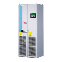
Siemens SINAMICS List Manual (1976 pages)
Brand:
Siemens
| Category:
Control Unit
| Size: 9.61 MB
Table of Contents
Function Diagrams
3
Faults and Alarms
6
SINAMICS G130/G150 List Manual (LH2), 07/2016, A5E03263479A
7
Table of Contents
9
1 Fundamental Safety
11
Parameters
12
Industrial Security
13
2 Parameters
15
Overview of Parameters
16
Safety Instructions
29
Number Ranges of Parameters
31
List of Parameters
34
Parameters for Data Sets
1069
Parameters for Drive Data Sets (DDS)
1071
Parameters for Encoder Data Sets (EDS)
1079
Parameters for Motor Data Sets (MDS)
1081
Parameters for Power Unit Data Sets (PDS)
1084
Parameters for Write Protection and Know-How Protection
1086
Parameters with "KHP_WRITE_NO_LOCK
1088
Parameters with "KHP_ACTIVE_READ
1089
Function Diagrams
1091
Table of Contents
1093
Explanation of the Function Diagrams
1101
CU320-2 Input/Output Terminals
1106
Control Unit Communication
1114
Proifienergy
1119
Profidrive
1122
Internal Control/Status Words
1167
Control Word, Speed Controller
1171
Status Word, Speed Controller
1172
Status Word Closed-Loop Control
1173
Status Word Closed-Loop Current Control
1174
Status Word, Monitoring Functions 1
1175
Status Word, Monitoring Functions 2
1176
Status Word, Monitoring Functions 3
1177
Control Word, Faults/Alarms
1178
Status Word, Faults/Alarms 1 and 2
1179
Sequence Control
1180
Sequencer
1180
Missing Enables, Line Contactor Control, Logic Operation
1180
Brake Control
1183
Basic Brake Control (R0108.14 = 0)
1183
Extended Brake Control, Zero-Speed Detection (R0108.14 = 1)
1183
Extended Brake Control, Open/Close Brake (R0108.14 = 1)
1183
Extended Brake Control, Signal Outputs (R0108.14 = 1)
1183
Safety Integrated Basic Functions
1188
Parameter Manager
1188
Monitoring Functions and Faults/Alarms
1188
SI Status CU, MM, CU + MM, Group STO
1188
S_STW1/2 Safety Control Word 1/2, S_ZSW1/2 Safety Status Word 1/2
1188
STO (Safe Torque Off), SS1 (Safe Stop 1)
1188
STO (Safe Torque Off), Safe Pulse Suppression
1188
SBC (Safe Brake Control), SBA (Safe Brake Adapter)
1188
Safety Integrated Extended Functions
1196
Parameter Manager
1196
SS1, SS2, SOS, Internal STOP B, C, D, F
1196
SBT (Safe Brake Test)
1196
Selection of Active Control Word
1196
SLS: Safely-Limited Speed
1198
SLP (Safely-Limited Position)
1201
SSM (Safe Speed Monitor)
1202
SDI: Safe Direction
1203
SAM: Safe Acceleration Monitor SBR: Safe Brake Ramp
1204
SI Motion Drive-Integrated Control Signals / Status Signals
1207
Safety Integrated TM54F
1210
Overview
1210
Parameter Manager
1210
Configuration, F-DI/F-DO Test
1210
Fail-Safe Digital Inputs (F-DI 0
1210
Fail-Safe Digital Inputs (F-DI 5
1210
Fail-Safe Digital Outputs (F-DO 0
1210
Basic Functions Control Interface (P9601.2/3 = 0 & P9601.6 = 1)
1210
Basic Functions Safe State Selection
1210
Basic Functions Assignment (F-DO 0
1210
Safety Integrated Profisafe
1223
Standard Telegrams
1223
Manufacturer-Specific Telegrams
1223
Setpoint Channel
1226
Overview
1226
Fixed Speed Setpoints
1226
Motorized Potentiometer
1226
Main/Supplementary Setpoint, Setpoint Scaling, Jogging
1226
Direction Limitation and Direction Reversal
1226
Skip Frequency Bands and Speed Limitations
1226
Basic Ramp-Function Generator
1226
Extended Ramp-Function Generator
1226
Ramp-Function Generator Selection, Status Word, Tracking
1226
Encoder Evaluation
1236
Vector Control
1240
Technology Functions
1271
7010 - Friction Characteristic
1271
External Armature Short-Circuit (EASC, P0300 = 2Xx or 4Xx)
1271
Internal Armature Short-Circuit (IASC, P0300 = 2Xx or 4Xx)
1271
DC Braking (P0300 = 1Xx)
1271
7020 - Synchronization
1271
Essential Service Mode (ESM)
1271
Technology Controller
1278
Fixed Values, Binary Selection (R0108.16 = 1 and P2216 = 2)
1278
Fixed Values, Direct Selection (R0108.16 = 1 and P2216 = 1)
1278
Motorized Potentiometer (R0108.16 = 1)
1278
Closed-Loop Control (R0108.16 = 1)
1278
DC-Link Voltage Controller (R0108.16 = 1)
1278
Signals and Monitoring Functions
1284
Overview
1284
Speed Signals 1
1284
Speed Signals
1284
Torque Signals, Motor Blocked/Stalled
1284
Load Monitoring (R0108.17 = 1)
1284
Thermal Monitoring, Motor, Motor Temperature Status Word Faults/Alarms
1284
Motor Temperature Model 1 (I2T)
1284
Motor Temperature Model
1284
Thermal Monitoring, Power Unit
1284
Diagnostics
1296
Overview
1296
Fault Buffer
1296
Alarm Buffer
1296
Faults/Alarms Trigger Word (R2129)
1296
Faults/Alarms Configuration
1296
Measuring Sockets (T0, T1, T2)
1296
Recorder Overview (R0108.5 = 1)
1296
Recorder Sequence Control (R0108.5 = 1)
1296
Function Diagrams
1296
Data Sets
1305
Command Data Sets (CDS)
1305
Drive Data Sets (DDS)
1305
Encoder Data Sets (EDS)
1305
Motor Data Sets (MDS)
1305
Power Unit Data Sets (PDS)
1305
Basic Infeed
1311
8710 - Overview
1311
8720 - Control Word, Sequence Control Infeed
1311
8726 - Status Word, Sequence Control Infeed
1311
8732 - Sequencer
1311
8738 - Missing Enables, Line Contactor Control
1311
Interface to the Basic Infeed Power Unit (Control Signals, Actual Values)
1311
Signals and Monitoring Functions (P3400.0 = 0)
1311
Terminal Board 30 (TB30)
1319
Overview
1319
Digital Inputs, Electrically Isolated (DI 0
1319
Digital Outputs, Electrically Isolated (DO 0
1319
Analog Inputs (AI 0
1319
Analog Outputs (AO 0
1319
Communication Board CAN10 (CBC10)
1325
Receive Telegram, Free PDO Mapping (P8744 = 2)
1325
Receive Telegram, Predefined Connection Set (P8744 = 1)
1325
Send Telegram, Free PDO Mapping (P8744 = 2)
1325
Send Telegram, Predefined Connection Set (P8744 = 1)
1325
Control Word, Canopen
1325
Status Word Canopen
1331
Terminal Module 31 (TM31)
1332
Overview
1332
Digital Inputs, Electrically Isolated (DI 0
1332
Digital Inputs, Electrically Isolated (DI 4
1332
Digital Relay Outputs, Electrically Isolated (DO 0
1332
Digital Inputs/Outputs, Bidirectional (DI/DO 8
1332
Digital Inputs/Outputs, Bidirectional (DI/DO 10
1332
Analog Input 0 (AI 0)
1332
Analog Input 1 (AI 1)
1332
Analog Outputs (AO 0
1333
Temperature Evaluation
1342
Terminal Module 120 (TM120)
1343
Temperature Evaluation Channels 0 and 1 (Kty/Ptc/Bimetal)
1343
Temperature Evaluation Channels 2 and 3 (Kty/Ptc/Bimetal)
1343
Terminal Module 150 (TM150)
1346
Temperature Evaluation Structure (Channels 0
1346
Temperature Evaluation 1X2-, 3-, 4-Wire (Channels 0
1346
Temperature Evaluation 2X2-Wire (Channels 0
1346
Voltage Sensing Module (VSM)
1350
Analog Inputs (AI 0
1350
Temperature Evaluation
1350
Basic Operator Panel 20 (BOP20)
1353
Control Word Interconnection
1353
4 Faults and Alarms
1355
Overview of Faults and Alarms
1356
Explanation of the List of Faults and Alarms
1361
Number Ranges of Faults and Alarms
1367
List of Faults and Alarms
1369
A.1 ASCII Table (Characters that Can be Displayed)
1942
A Appendix . . . . . . . . . . . . . . . . . . . . . . . . . . . . . . . . . . . . . . . . . . . . . . . . . . . . . . . . . . . . . . . . . . . . . . 1941
1945
List of Abbreviations
1945
References
1954
Index
1961
Advertisement
Siemens SINAMICS Operating Instructions Manual (446 pages)
Brand:
Siemens
| Category:
Construction Equipment
| Size: 15.9 MB
Table of Contents
Preface
3
Table of Contents
5
1 Fundamental Safety Instructions
13
General Safety Instructions Related to the Hardware
13
General Safety Instructions Related to Software
14
Warranty and Liability for Application Projects
14
Industrial Security
15
Additional Specific "Security Measures
16
2 System Description
17
Introduction
17
System Overview
17
System Requirements and Design
17
Applications
18
Grab Ship Unloader (GSU) Without Camera Measuring System
18
STS Container Cranes with Camera Measuring System
19
Overview of Operating Modes, Functions and Required Licenses
20
Product Structure
22
Scope of Supply
22
3 Overview of the Software
25
Application Projects
25
SCOUT Project GSU
25
SCOUT Project STS
27
Addon Software Structure
28
Structure of the SCOUT Part of the Project
28
Structure of the Function Module
30
Global Variables - Connection between the Components
33
Overview
33
Naming Scheme for the Unit-Global Variables
35
Addon Technology - Basic Technology
35
Addon Technology - Technology Objects
36
Polarity of Velocities and Position Values
37
Sway Control Function Blocks
37
Addon DCC Library
37
Dcc_Schoist
38
Dcc_Sctrolley
40
Dcc_Sctargets
42
Dcc_Scobstacles
44
Dcc_Sccamera
46
Dcc_Sctls2
48
Dcc_Scintpo
52
Dcc_Sccommon
54
Dcc_Scdiag
57
Addon FB Library
58
Fb_Commonplctoaddon
58
Fb_Commonaddontoplc
60
Fb_Hoistplctoaddon
61
Fb_Hoistaddontoplc
62
Fb_Trolleyplctoaddon
63
Fb_Trolleyaddontoplc
65
Fb_Intpoplctoaddon
66
Fb_Intpoaddontoplc
67
Fb_Tlsplctoaddon
68
Fb_Tlsaddontoplc
69
Fb_Targetsplctoaddon
70
Fb_Targetsaddontoplc
71
Fb_Obstacleplctoaddon
73
Fb_Obstacleaddontoplc
74
Fb_Adddataplctoaddon
75
Fb_Adddataaddontoplc
77
Fb_Receive_Analysis
79
Fb_Send_Preparation
80
Fb_Readwrite_Mv440
81
4 Communication Interface to SIMATIC S7
83
SIMATIC S7 → SIMOTION D for Addon
83
Common
83
Hoist
86
Trolley
88
Intpo
90
Tls
90
Targets
93
Obstacles
95
Adddata
96
SIMOTION D for Addon → SIMATIC S7
97
Common
97
Hoist
100
Trolley
102
Intpo
104
Tls
104
Targets
106
Obstacles
107
Adddata
107
5 Configuration
109
Requirement
109
Overview of the Configuring Steps to be Performed
110
Performing Setup
111
Importing the (SCOUT) Application Project of the Addon Technology
111
PROFINET Configuration
112
Configuring the Connection
112
General Information
120
Defining the Telegram
121
Copying the Address List
121
Copying the Addon FB Library
123
Copying MCC Source Files
126
Inserting DCC Blocks
127
Establishing the Connection between Basic Technology and Addon
131
Connection between Skew Damping Technology Object and DCC Block TLS2
132
Execution System
134
Saving, Compiling and Checking Consistency
134
Downloading the User Project to the CF Card
135
Transferring Language Files, Online Help Files, JAVA Files and Parameter Files to the CF Card
138
Creating the License Key and Downloading It to the CF Card
140
Communication Tests for the STS Application Project
141
6 Sway Control Function Description
147
Activation of the Addon Technology "Sway Control" in the Basic Technology
147
Sway Control Operating Modes
148
Manual Mode (MAN)
149
Method of Operation
149
Activation
150
Control
150
Positioning (POS)
152
Method of Operation
152
Activation
152
Control
152
Semi-Automatic Mode (SAM)
155
Method of Operation
155
Activation
155
Control
155
Sway Neutralization Load Position (SNL)
158
Method of Operation
158
Activation
158
Control
158
Sway Neutralization Drive Position (SND)
158
Functional Principle
158
Control
159
Generating the TRAVEL Control Bit
159
Activating/Deactivating the "Sway Control" Function
160
Calculation of the Pendulum Deflection
160
Activating the "Sway Control" Function
162
Deactivating the "Sway Control" Function
162
Braking Distance Correction (S_Corr) Due to Influence of Sway Control
163
Drive Activation and Brake Control
163
Controlled Stop
164
Terminating a Travel Operation
164
Acceleration and Deceleration Behavior
165
Immersion Point
166
Internal Immersion Point
166
External Immersion Point
169
Blocked Regions
170
Definition of Terms
170
Fixed Blocked Regions
174
External Variable Blocked Regions
174
Internally Learned Variable Blocked Regions
176
Defining the Blocked Regions
177
Locking State of the Spreader as a Function of the Spreader Constellation
178
Spreader Constellations
178
Lock Bits
179
Forming Blocked Regions During the Learning Travel
180
Forming the Immersion Point During a Learning Travel
183
Collision Protection - Soft Approach
185
Soft Approach
185
Position-Dependent Monitoring Functions of Semi-Automatic Mode (SAM) / Manual Mode (MAN)
189
Velocity-Dependent Monitoring Functions before Semi-Automatic Mode Starts
192
Selection of the Control Method
193
Selection
193
Conventional Control
193
Time-Optimized Control
194
General Information
194
Relaxation Oscillations with GSU
194
Target Generator
195
Requirement
195
Parameterization
196
Control
196
Initialization
196
Loading or Unloading the Ship
196
Specifying Starting Position and Target Position
196
End of a Loading or Unloading Operation
199
Diagnostics
200
Automatic Target Specification
201
Offset for the Target Position
203
Bay Scanner
204
Using a Bay Scanner
204
Conversion of the Bay Scanner Values
209
Calculation of 2D Trajectory in Semi-Automatic Mode (SAM)
213
Sway Control Only When Stopping
217
Suppressing the Opposite Direction
217
Approaching the Waiting Position
218
Starting SAM Mode after a Manual Hoist Operation
218
Slack Rope
219
Override
219
Influencing the Lowering Point in SAM Travel from WS to LS
221
Hoist Takeover
221
Minimum Hoisting Height
224
Velocity for Automatic Lowering
226
Adjusting the Trajectory During Inclined Travel in SAM
227
Special Aspects of GSU Applications
228
Differences between STS and GSU
228
On-The-Fly Unloading
229
Use
229
Activating On-The-Fly Unloading
232
Influence of Parameters P75/P76 and P158 on the Trajectory
233
Procedure for Changing Targets over the Hopper
235
7 TLS Control Function Description
237
Requirements
238
Mechanical Requirements for TLS with a Hydraulic System
238
Mechanical Requirements for TLS with a Hydraulic System and Electric Drive
239
TLS Modes and TLS Functions
241
Cylinder Jogging" Mode
241
Go to Zero Positions" Mode
243
TLS Jogging" Mode
247
TLS Positioning" Mode
250
Versions of "TLS Positioning" Mode
250
V1: Move to Internally Stored Trim, List and Skew Positions
252
V2: Move to Externally Defined Skew Position and Internally Stored Trim and List Positions
254
Skew Damping for Damping Skew Oscillation" Function
255
Skew Damping Via Electric Drive" Function
255
Skew Damping Via Cylinders" Function
258
Control of a Cylinder Movement
259
Controlling Movement of the Electric Drive
259
Control of the Modes and the Skew Damping for the Hydraulic System
260
Controlling Travel and Skew Damping with Electric Drive
261
8 SIMOCRANE Cecomm Commissioning and Diagnostic Program
263
Installing
263
Design and Operation
264
Establishing a Connection to the Device
266
Menu Bar
267
Monitor (Tab)
271
Sway Control Monitors
275
TLS Monitors
277
Editing Addon Parameters
283
Overview
283
Call and Navigation in the Parameter Menus
284
Activating a Parameter Set
284
Editing a Parameter Set
285
Changing a Parameter
285
Copying a Parameter Set
286
Loading the Saved Parameter Sets
286
Saving All Sets of Parameters
286
Switching over Parameter Sets
286
Setting Default Values
287
More Functions
287
File Manager
288
Diagram - Trace Function
289
Procedure for Recording Diagrams
290
Elements and Functionality of the Diagram User Interface
293
X/Y Diagram
304
TLS Trace
306
Effective Pendulum Length
307
Logger
309
Introduction
309
Data Retention and Storage
309
Method of Operation
311
Special Situations
313
Handling the "Logger" Function in SIMOCRANE Cecomm
313
Display of Blocked Regions
317
9 Commissioning Addon Software
319
Requirements
319
Communication of the Camera Measuring System Via Ethernet
319
Commissioning Requirements for Addon Software
320
General Requirements
320
Preparing the PLC Program
322
Preparing the Converters
322
Setting the Access Code
323
Setting the Language
323
Checking of the Communication between PLC and SIMOTION
324
Setting up FTP File Access
325
Sway Control Commissioning
328
Method of Operation of Sway Control
328
Commissioning the Sway Control System
331
Commissioning Steps in the Commissioning Menu
331
Selection of the Control Method
337
Effective Pendulum Length Correction
337
Setting the Permissible Residual Sway
339
Settings to Monitor the Oscillation State
339
Setting the Damping Factor
339
Defining the Activation Velocity and on Delay
340
Setting the Time Constants for Trolley (P153) and Hoist (P154)
340
Commissioning Positioning Mode (POS)
342
Selecting External and Internal Targets
342
Changing the Coordinate System
343
Position Controller Setting
345
Other Settings
346
Commissioning Semi-Automatic (SAM) Mode
347
On-The-Fly Unloading, GSU Only
349
Commissioning TLS (Hydraulic System)
350
System Requirements
350
Activating the TLS Functions
351
Parameterization of the Actual Positions
351
Parameterizing "Cylinder Jogging" Mode
352
Parameterization of the Central Positions of the Cylinders
354
TLS Inching and Go to Zero Positions
356
Conversion of Cylinder Positions, Angle of Rotation
357
Calculating the Effective Pendulum Length for the Skew Oscillation
357
Monitoring the Camera Measuring System
360
Parameterization of Observer
361
Activates the "Skew Damping" Function
361
Optional Adaptations
361
Commissioning TLS (Hydraulic System with Electric Drive)
362
System Requirements
362
Commissioning Cylinders
363
Evaluation of the Current Position of the Skew Drive Spindle
363
Position Controller Setting (P328)
364
Setting the Limit for Set Position P324
365
Kinematic Transformation of Skew Drive Position, Angle of Rotation
365
Parameterization of Skew Damping
366
Commissioning TLS (Skew Damping with Electric Drive Only)
367
System Requirements
367
Activation of TLS Function and Skew Drive
368
Commissioning Cylinders and Electric Drive
368
10 Alarm, Error, and System Messages
369
Following Error Monitoring
369
Velocity Monitoring
370
Monitoring of Start of Sway Control
371
Monitoring the Oscillation State
371
Monitoring of Excessive Oscillations
372
Monitoring of the Sway Control System
372
Error Messages
373
General Information
373
SIMOCRANE Censor Error List
373
Error List Addon
374
Overview
374
Brief Description
374
General and Severe Errors
376
Error in the Limit or Prelimit Switch Area
379
Error in Semi-Automatic Mode
380
Other Errors 1
384
Other Errors 2
385
SIMOCRANE Cecomm Diagnostic Program
387
Troubleshooting/Faqs
387
Error List TLS
387
11 Parameters
393
Overview of the Parameter List
393
Trolley
393
Hoist
400
Sway Control System
407
General
408
Camera Measuring System/Reflector
412
Travel Characteristic
413
Controlled Variables
418
Tls
420
Appendix
435
Service and Maintenance
435
References
435
List of Abbreviations
436
Assignment of Signal Names
437
Variable Signals
437
Glossary
443
Siemens SINAMICS Configuration Manual (236 pages)
Industrial Security, Medium-voltage converter
Brand:
Siemens
| Category:
Industrial Electrical
| Size: 15.49 MB
Table of Contents
Table of Contents
3
1 Introduction
7
2 Safety Instructions
9
Note on Safety Integrated
10
Why Is Industrial Security so Important
12
Security Measures in Automation and Drive Technology
14
Security Management
16
4 General Security Measures
19
Plant Security
20
Network Security
21
Network Segmentation with SCALANCE S
22
System Integrity
26
Virus Scanner
28
Whitelisting
29
5 Security Measures for SINAMICS
31
Write Protection
32
Know-How Protection
34
Features of Know-How Protection
35
Configuring Know-How Protection
37
Loading Know-How Protected Data to the File System
43
Overview of Important Parameters
47
Parameters: Access Levels + Password
48
Communication Services and Used Port Numbers
49
Web Server
52
Requirements and Addressing
53
Configuring the Web Server
54
Assigning a Password
56
Access Protection and Rights
59
Access Protection for Parameter Lists in the Web Server
61
Starting the Web Server
62
Displaying Device Information
64
Displaying Diagnostic Functions
65
Loading a Multiple Trace
66
Displaying Messages
67
Displaying Faults and Alarms
68
Deleting a Parameter List
70
Displaying and Changing Drive Parameters
72
Certificates for the Secure Data Transfer
73
Using the Standard Configuration of the Certificate
75
Generating Your Own Certificates
76
Messages and Parameters
77
SINAMICS Startdrive and Starter
79
SINAMICS Drive Control Chart (DCC)
80
Use Write and Know-How Protection
82
A.1 Communication
83
A.1.1.1 Profidrive Application Classes
85
A.1.1.2 Cyclic Communication
86
A.1.1.3 Parallel Operation of Communication Interfaces
90
A.1.1.4 Acyclic Communication
93
A.1.1.5 Diagnostics Channels
105
A.1.2 Communication Via PROFIBUS DP
113
A.1.2.2 Commissioning PROFIBUS
117
A.1.2.3 Slave-To-Slave Communication
124
A.1.2.4 Messages Via Diagnostic Channels_Profibus
135
A.1.3 Communication Via PROFINET IO
137
A.1.3.2 RT Classes for PROFINET IO
147
A.1.3.3 Profinet Gsdml
152
A.1.3.4 Communication with CBE20
153
A.1.3.5 Communication Via PROFINET Gate
154
A.1.3.6 PROFINET with 2 Controllers
158
A Communication
160
A.1.3.7 PROFINET Media Redundancy
169
A.1.3.9 Support of I&M Data Sets 1...4
173
A.1.4 Communication Via MODBUS TCP
175
A.1.4.2 Configuring Modbus TCP Via Interface X150
177
A.1.4.3 Configuring Modbus TCP Via Interface X1400
178
A.1.4.4 Mapping Tables
179
A.1.4.5 Write and Read Access Using Function Codes
181
A.1.4.6 Communication Via Data Set 47
184
A.1.4.7 Communication Procedure
187
A.1.4.8 Messages and Parameters
188
A.1.5 Communication Via Ethernet/Ip
189
A.1.5.3 Requirements for Communication
191
A.1.5.5 Supported Objects
192
A.1.5.6 Integrate the Drive Device into the Ethernet Network Via DHCP
202
A.1.6 Communication Via SINAMICS Link
203
A.1.6.2 Topology
206
A.1.6.3 Configuring and Commissioning
207
A.1.6.4 Example
211
A.1.6.5 Communication Failure When Booting or in Cyclic Operation
214
A.1.7 Communication Services and Used Port Numbers
215
A.1.8 Time Synchronization between the Control and Converter
218
A.1.8.1 Settings
220
A.1.8.2 Messages and Parameters
221
C.1 Additional Information
225
100 C References
227
Glossary
227
Index
233
Advertisement
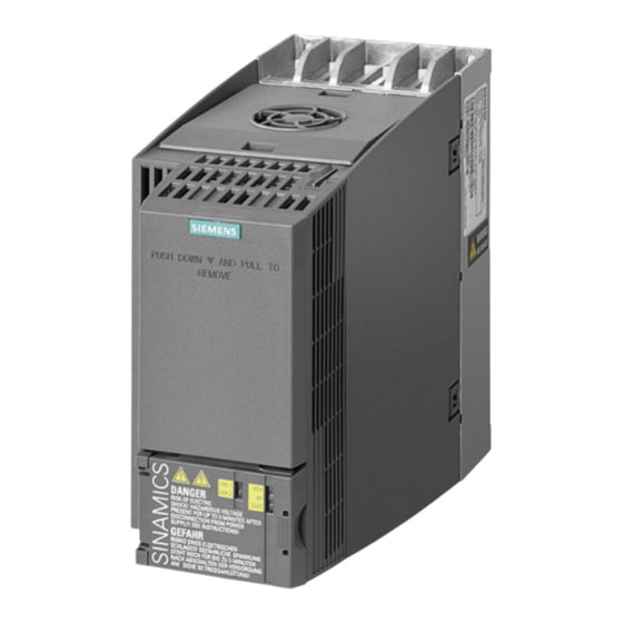
Siemens SINAMICS Equipment Manual (104 pages)
Medium-voltage drives, Supplementary component descriptions
Brand:
Siemens
| Category:
DC Drives
| Size: 4.13 MB
Table of Contents
Introduction
3
Table of Contents
5
Manual
8
1 Introduction
9
2 Security Information
11
3 Control Units
13
Control Unit CU320-2 PN (PROFINET)
13
Description
13
Interface Description
14
Overview
14
X100-X103 DRIVE-Cliq Interfaces
16
X122 Digital Inputs/Outputs
17
X132 Digital Inputs/Outputs
19
X124 Electronics Power Supply
20
X127 LAN (Ethernet)
21
X140 Serial Interface (RS 232)
22
X150 P1/P2 Profinet
23
Measuring Socket
23
Buttons
24
Slot for Memory Card
24
Meaning of the Leds
25
Description of the LED Statuses
25
Behavior of the Leds During Booting
26
Behavior of the Leds in the Operating State
27
Control Unit CU320-2 DP (PROFIBUS)
29
Description
29
Interface Description
30
Overview
30
X100-X103 DRIVE-Cliq Interfaces
32
X122 Digital Inputs/Outputs
33
X132 Digital Inputs/Outputs
35
X124 Electronics Power Supply
36
X126 Profibus
37
PROFIBUS Address Switch
38
X127 LAN (Ethernet)
39
X140 Serial Interface (RS 232)
40
Measuring Sockets
40
Buttons
41
Slot for Memory Card
41
Meaning of the Leds
42
Description of the LED Statuses
42
Behavior of the Leds During Booting
42
Behavior of the Leds in the Operating State
44
4 Option Boards
47
Communication Board CAN CBC10
47
Description
47
Interface Description
48
Overview
48
X451 CAN Bus Interface
49
X452 CAN Bus Interface
49
2-Pin SMD DIL Switch
50
Meaning of the LED
51
Communication Board Ethernet CBE20
51
Interface Description
52
Overview
52
X1400 Ethernet Interface
52
Meaning of the Leds
53
5 Terminal Modules
57
Terminal Module TM15
57
Description
57
Interface Description
58
Overview
58
X500/X501 DRIVE-Cliq Interfaces
59
X520 Bidirectional Digital Inputs/Outputs
59
X521 Bidirectional Digital Inputs/Outputs
60
X522 Bidirectional Digital Inputs/Outputs
60
X524 Electronics Power Supply
61
Meaning of the Leds
61
Technical Data
62
Terminal Module TM31
63
Description
63
Interface Description
64
Overview
64
X500/X501 DRIVE-Cliq Interfaces
65
X520 Digital Inputs
65
X521 Analog Inputs
66
S5 Current/Voltage Changeover Switch for Analog Inputs
67
X522 Analog Outputs/Temperature Sensor
67
X524 Electronics Power Supply
68
X530 Digital Inputs
69
X540 Auxiliary Voltage for the Digital Inputs
69
X541 Bidirectional Digital Inputs/Outputs
71
X542 Relay Outputs
72
Meaning of the Leds
73
Technical Data
73
Terminal Module TM150
74
Description
74
Interface Description
75
Overview
75
X500/X501 DRIVE-Cliq Interfaces
76
X524 Electronics Power Supply
76
X531-X536 Temperature Sensor Inputs
77
Meaning of the Leds
79
Technical Data
79
6 Voltage Sensing Module VSM10
81
Description
81
Interface Description
82
Overview
82
X500 DRIVE-Cliq Interface
83
X520 Analog Inputs/Temperature Sensor
84
X521 Three-Phase Voltage Sensing up to 100 V 3-Ph. AC
85
X522 Three-Phase Voltage Sensing up to 690 V 3-Ph. AC
86
X524 Electronics Power Supply
86
X530 Neutral Point Grounding
87
Meaning of the Leds
88
7 Sensor Module Cabinet-Mounted SMC30
89
Description
89
Interface Description
90
Overview
90
X500 DRIVE-Cliq Interface
91
X520 Encoder System Interface
91
X521 / X531 Alternative Encoder System Interface
93
X524 Electronics Power Supply
94
Meaning of Leds
95
Technical Data
96
Index
101
Siemens SINAMICS Quick Install Manual (2 pages)
Brand:
Siemens
| Category:
Media Converter
| Size: 2.46 MB
Siemens SINAMICS Quick Install Manual (2 pages)
Brand:
Siemens
| Category:
Media Converter
| Size: 2.3 MB
Advertisement
Related Products
Siemens SINAMICS DCM
Siemens SINAMICS CU240S
Siemens SINAMICS CU240S PN-F
Siemens SINAMICS CU250D-2
Siemens SINAMIC G130
Siemens SINAMICS CONNECT 500
Siemens SINAMICS Startdrive
Siemens SINAMICS RAILCTRL
Siemens SINAMICS S Series
Siemens SINAMICS G120D-2 CU250D-2
Siemens Categories
Controller
Control Unit
Industrial Equipment
Washer
Switch
More Siemens Manuals
Login
Sign In
OR
Sign in with Facebook
Sign in with Google
Upload manual
Upload from disk
Upload from URL