Siemens SINAMICS DCM User Manual
Dc converter
Hide thumbs
Also See for SINAMICS DCM:
- List manual (1205 pages) ,
- Operating instructions manual (715 pages) ,
- Manual (705 pages)
Table of Contents
Advertisement
Advertisement
Table of Contents

Related Manuals for Siemens SINAMICS DCM


Summary of Contents for Siemens SINAMICS DCM
- Page 3 Introduction Principle of the dual channel architecture SINAMICS DCM STO stop Category 0 with one switching device SS1 stop Category 1 with DC Converter one switching device Application document for functional safety STO, SS1 (ISO 13849-1) STO, two switching devices...
- Page 4 Note the following: WARNING Siemens products may only be used for the applications described in the catalog and in the relevant technical documentation. If products and components from other manufacturers are used, these must be recommended or approved by Siemens. Proper transport, storage, installation, assembly, commissioning, operation and maintenance are required to ensure that the products operate safely and without any problems.
-
Page 5: Table Of Contents
Table of contents Introduction..........................11 Important note ........................11 Preliminary remarks......................11 1.2.1 Safe Torque Off (STO) ...................... 12 1.2.2 Safe Stop 1 (SS1, time-controlled) ..................12 1.2.3 Using EMERGENCY STOP ....................13 Application overview ......................13 Armature circuit with one switching device ................. 14 Armature circuit with two switching devices ................ - Page 6 Table of contents STO stop Category 0, several power units ..................39 Description .........................39 STO circuit example with two power units and circuit breakers..........40 STO circuit example with two power units and power contactors .........41 SS1 stop Category 1 for several power units .................. 43 Description .........................43 SS1 circuit example with two power units and circuit breakers ..........45 SS1 circuit example with two power units and circuit breakers ..........46...
- Page 7 Table of contents Standards ........................... 71 Recommended safety relays ......................73 Connection circuit diagrams for the switching devices ..............75 Recommended circuit breakers and power contactors ..............81 Application document for functional safety STO, SS1 (ISO 13849-1) Compact User Manual, 09/2016, A5E34871844AM...
- Page 8 Table of contents Application document for functional safety STO, SS1 (ISO 13849-1) Compact User Manual, 09/2016, A5E34871844AM...
- Page 9 Copyright Copyright © 2016 Siemens AG. Reproduction or transmissions of these safety function examples or extracts thereof are forbidden without the express written authority of Siemens Manuals and application notes on the Internet The manuals and application documents are available in the Internet: Manuals (https://support.industry.siemens.com/cs/ww/en/ps/13298)
- Page 10 Introduction Application document for functional safety STO, SS1 (ISO 13849-1) Compact User Manual, 09/2016, A5E34871844AM...
-
Page 11: Introduction
By using these safety functional examples, you acknowledge the fact that Siemens cannot be held liable for any claims or damages above and beyond the liability described above. We reserve the right to make changes to these safety function examples at any time without prior notice. -
Page 12: Safe Torque Off (Sto)
Introduction 1.2 Preliminary remarks 1.2.1 Safe Torque Off (STO) Safe Torque Off is a safety function to avoid unexpected starting in accordance with EN 60204-1. STO prevents the supply of energy to the motor, which can generate a torque and corresponds to Stop Category 0. The motor is stopped in an uncontrolled fashion. Notes ●... -
Page 13: Using Emergency Stop
Introduction 1.3 Application overview 1.2.3 Using EMERGENCY STOP STO and SS1 are suitable for the EMERGENCY STOP function when the following preconditions are carefully taken into consideration: The user must evaluate as to whether an immediate shutdown of the energy feed for STO does not result in dangerous states (uncontrolled stopping - STOP category 0 according to EN ISO 13850). -
Page 14: Armature Circuit With One Switching Device
After STO has been selected, the E-Stop function of the drive is activated using the safety relay (supply at terminal 105 is disconnected). When setting p51616=0, using Alpha-W pulses, the SINAMICS DCM reduces the armature current - and then inhibits the firing pulses and also interrupts the main contactor control (terminals 109-110). The active E-Stop state is integrated in the feedback circuit of the safety relay using digital output (DO3) via a relay. -
Page 15: Field Circuit Description
Introduction 1.6 Field circuit description Via the expansion device, independent of the SINAMICS DCM state, a safety-related coupling relay is switched, which immediately opens the circuit breaker with the undervoltage coil - or for a power contactor, disconnects the solenoid. -
Page 16: Safety Shutdown (E-Stop)
Introduction 1.7 Safety shutdown (E-STOP) Safety shutdown (E-STOP) Note The E-STOP function alone does not represent a safety function. The E-STOP function forces the "line contactor closed" relay to drop out, activating the relay contact (terminals XR1-109 and -110) for the main contactor control within approximately 20 ms, independent of the semiconductor components and Control Unit (CUD) functions. -
Page 17: Parameterizing The Digital Outputs
Introduction 1.8 Parameterizing the digital outputs Parameterizing the digital outputs In order to signal to the safety relay that the drive E-STOP function has been activated, the following parameters must be set at the SINAMICS DC MASTER: Digital output DO3 at connector X177.22 controls relay K . -
Page 18: Parameterizing The Digital Input For Ss1 Off3
Introduction 1.9 Parameterizing the digital input for SS1 OFF3 Parameterizing the digital input for SS1 OFF3 Digital input DI/DO 4 (terminal X177.15 on the CUD electronics module) of the SINAMICS DC MASTER must be used for the SS1 function. This digital input must be parameterized so that signal OFF3 (fast stop) is controlled in all of the command data sets (CDS) used Setting p849 (OFF3) p53010[8] (DI/DO 4) Setting p50296 (OFF3 down ramp) e.g. -
Page 19: Abbreviations And Circuit Diagram Symbols
Introduction 1.10 Abbreviations and circuit diagram symbols 1.10 Abbreviations and circuit diagram symbols Armature contactor A[n] Field contactor Safety-related interface relay to control the armature contactor AH[n] Safety-related interface relay to control the field contactor Relay, feedback signal E-Stop EP[n] Programmable digital output 2 2 = X177.21 (field contactor control) Programmable digital output 3 = X177.22 (feedback signal E-Stop active) DI/DO4... - Page 20 Introduction 1.10 Abbreviations and circuit diagram symbols Application document for functional safety STO, SS1 (ISO 13849-1) Compact User Manual, 09/2016, A5E34871844AM...
-
Page 21: Principle Of The Dual Channel Architecture
Principle of the dual channel architecture The following two block diagrams show the two-channel architecture of the safety system, so that after the first two faults – each in one of the two channels – the system can fail. Safety block diagram of a drive without field excitation Safety block diagram of a drive with field excitation Path 3 is not considered to be a safety-related switch-off signal path as the field remanence of the DC motor –... - Page 22 Principle of the dual channel architecture Dual channel architecture, color-coded using the application of SS1 as example Application document for functional safety STO, SS1 (ISO 13849-1) Compact User Manual, 09/2016, A5E34871844AM...
-
Page 23: Sto Stop Category 0 With One Switching Device
When selecting the safety function (actuating the Emergency Stop pushbutton), the instantaneous NO contacts are immediately opened in the 3SK1122-2CB41 safety relay. As a consequence, the E-Stop function is initiated at the SINAMICS DCM. The SINAMICS DCM reduces the armature current, inhibits the firing pulses and opens the armature contactor. -
Page 24: Sto Circuit Example With One 3Wl Circuit Breaker
STO stop Category 0 with one switching device 3.2 STO circuit example with one 3WL circuit breaker STO circuit example with one 3WL circuit breaker Application document for functional safety STO, SS1 (ISO 13849-1) Compact User Manual, 09/2016, A5E34871844AM... -
Page 25: Sto Circuit Example With One Power Contactor
STO stop Category 0 with one switching device 3.3 STO circuit example with one power contactor STO circuit example with one power contactor Application document for functional safety STO, SS1 (ISO 13849-1) Compact User Manual, 09/2016, A5E34871844AM... - Page 26 STO stop Category 0 with one switching device 3.3 STO circuit example with one power contactor Application document for functional safety STO, SS1 (ISO 13849-1) Compact User Manual, 09/2016, A5E34871844AM...
-
Page 27: Ss1 Stop Category 1 With One Switching Device
DI/DO4 (X177.15). The drive is braked along a ramp that can be adjusted using p50269. The down ramp is not monitored. As soon as the SINAMICS DCM identifies that the motor is at a standstill, the firing pulses are inhibited and the power disconnected. -
Page 28: Ss1 Circuit Example With One 3Wl Circuit Breaker
SS1 stop Category 1 with one switching device 4.2 SS1 circuit example with one 3WL circuit breaker SS1 circuit example with one 3WL circuit breaker Application document for functional safety STO, SS1 (ISO 13849-1) Compact User Manual, 09/2016, A5E34871844AM... -
Page 29: Ss1 Circuit Example With One Power Contactor
SS1 stop Category 1 with one switching device 4.3 SS1 circuit example with one power contactor SS1 circuit example with one power contactor Application document for functional safety STO, SS1 (ISO 13849-1) Compact User Manual, 09/2016, A5E34871844AM... - Page 30 SS1 stop Category 1 with one switching device 4.3 SS1 circuit example with one power contactor Application document for functional safety STO, SS1 (ISO 13849-1) Compact User Manual, 09/2016, A5E34871844AM...
-
Page 31: Sto, Two Switching Devices In Series
When selecting the safety function (actuating the EMERGENCY STOP pushbutton), the instantaneous NO contacts are immediately opened in the 3SK1122-2CB41 safety relay, which immediately causes the E-Stop function to be initiated at the SINAMICS DCM. The SINAMICS DCM reduces the armature current, inhibits the firing pulses and opens the armature contactor. -
Page 32: Sto Circuit Example With Two 3Wl Circuit Breakers Connected In Series
STO, two switching devices in series 5.2 STO circuit example with two 3WL circuit breakers connected in series STO circuit example with two 3WL circuit breakers connected in series Application document for functional safety STO, SS1 (ISO 13849-1) Compact User Manual, 09/2016, A5E34871844AM... -
Page 33: Sto Circuit Example With Two Power Contactors Connected In Series
STO, two switching devices in series 5.3 STO circuit example with two power contactors connected in series STO circuit example with two power contactors connected in series Application document for functional safety STO, SS1 (ISO 13849-1) Compact User Manual, 09/2016, A5E34871844AM... - Page 34 STO, two switching devices in series 5.3 STO circuit example with two power contactors connected in series Application document for functional safety STO, SS1 (ISO 13849-1) Compact User Manual, 09/2016, A5E34871844AM...
-
Page 35: Ss1, Two Switching Devices Connected In Series
DIO4 (X177.15). The drive is braked along a ramp that can be adjusted using p50269. The down ramp is not monitored. As soon as the SINAMICS DCM identifies that the motor is at a standstill (speed of 0), the firing pulses are inhibited and the power disconnected. -
Page 36: Ss1 Circuit Example With Two 3Wl Circuit Breakers Connected In Series
SS1, two switching devices connected in series 6.2 SS1 circuit example with two 3WL circuit breakers connected in series SS1 circuit example with two 3WL circuit breakers connected in series Application document for functional safety STO, SS1 (ISO 13849-1) Compact User Manual, 09/2016, A5E34871844AM... -
Page 37: Ss1 Circuit Example With Two Power Contactors Connected In Series
SS1, two switching devices connected in series 6.3 SS1 circuit example with two power contactors connected in series SS1 circuit example with two power contactors connected in series Application document for functional safety STO, SS1 (ISO 13849-1) Compact User Manual, 09/2016, A5E34871844AM... - Page 38 SS1, two switching devices connected in series 6.3 SS1 circuit example with two power contactors connected in series Application document for functional safety STO, SS1 (ISO 13849-1) Compact User Manual, 09/2016, A5E34871844AM...
-
Page 39: Sto Stop Category 0, Several Power Units
The motor current therefore goes to zero and in turn, the motor torque also goes to zero. The motor coasts down. Up to 6 SINAMICS DCM units can be connected in parallel or series. For all units, the E- Stop terminals - as well as the armature contacts - must be integrated via safety relays. This is realized with the additional safety-related output expansions 3SK1211-2BB40. -
Page 40: Sto Circuit Example With Two Power Units And Circuit Breakers
STO stop Category 0, several power units 7.2 STO circuit example with two power units and circuit breakers STO circuit example with two power units and circuit breakers Application document for functional safety STO, SS1 (ISO 13849-1) Compact User Manual, 09/2016, A5E34871844AM... -
Page 41: Sto Circuit Example With Two Power Units And Power Contactors
STO stop Category 0, several power units 7.3 STO circuit example with two power units and power contactors STO circuit example with two power units and power contactors Application document for functional safety STO, SS1 (ISO 13849-1) Compact User Manual, 09/2016, A5E34871844AM... - Page 42 STO stop Category 0, several power units 7.3 STO circuit example with two power units and power contactors Application document for functional safety STO, SS1 (ISO 13849-1) Compact User Manual, 09/2016, A5E34871844AM...
-
Page 43: Ss1 Stop Category 1 For Several Power Units
(X177.15). The drive is braked along a ramp that can be adjusted using p50269. The down ramp is not monitored. As soon as the SINAMICS DCM identifies that the motor is at a standstill (speed of 0), the firing pulses are inhibited and the power disconnected. - Page 44 SS1 stop Category 1 for several power units 8.1 Description 2 = 0.5 ... 30 s 4 = 5 ... 300 s Application document for functional safety STO, SS1 (ISO 13849-1) Compact User Manual, 09/2016, A5E34871844AM...
-
Page 45: Ss1 Circuit Example With Two Power Units And Circuit Breakers
SS1 stop Category 1 for several power units 8.2 SS1 circuit example with two power units and circuit breakers SS1 circuit example with two power units and circuit breakers Application document for functional safety STO, SS1 (ISO 13849-1) Compact User Manual, 09/2016, A5E34871844AM... -
Page 46: Ss1 Circuit Example With Two Power Units And Circuit Breakers
SS1 stop Category 1 for several power units 8.3 SS1 circuit example with two power units and circuit breakers SS1 circuit example with two power units and circuit breakers Application document for functional safety STO, SS1 (ISO 13849-1) Compact User Manual, 09/2016, A5E34871844AM... -
Page 47: Evaluating The Safety Functions According To En Iso 13849 When Using One Switching Device
The safety function is split up into three partial systems: Detect → Evaluate → Respond As the Respond partial system comprises the E-Stop channel of the SINAMICS DCM and the power switching device, this is again split up. The assignment to the partial systems is color-coded in the following block diagram: Orange = "Detect"... -
Page 48: Evaluation Of "Detect
: High, DC: High, measures against CCF: Fulfilled Calculation of MTTF Parameter Value Reason Definition 1 * 10 Manufacturers data SIEMENS AG B10 value EMERGENCY STOP command device Percentage of dangerous failures 0.2 (20 %) Manufacturers data EMERGENCY STOP command device... -
Page 49: Evaluation Of "Evaluate
Average probability of a dangerous 5.42 E-09 failure per hour Parameter Component Value Definition (basic device advanced) 3SK1121 basic device 3.7 E-09 SIEMENS AG (output expansion) 3SK1211 output ex- 1.7 E-09 pansion (coupling relay K Article number 2.02 E-11 Phoenix Contact AH[n]... -
Page 50: Evaluation Of "Respond
Evaluating the safety functions according to EN ISO 13849 when using one switching device 9.3 Evaluation of "Respond" Evaluation of "Respond" 9.3.1 Evaluation of "Respond" with one power switching device 9.3.1.1 Evaluation of an 3WL circuit breaker Result, 3WL circuit breaker K Result Reason The values for determination are listed in the following ta-... - Page 51 EMERGENCY STOP (testing the ponent EMERGENCY STOP) Determination of the PL E-Stop for SINAMICS DCM channel 2 Parameter Value Reason MTTF High MTTF >...
-
Page 52: Evaluation Of A Power Contactor
Calculation of the MTTF for power contactor, channel 1 Parameter Value Reason 1 * 10 Manufacturers data SIEMENS AG B10 value power contactor Percentage of dangerous failures 0.73 (73 %) Manufacturers data EMERGENCY STOP command device 365 days per year... -
Page 53: Result When Using A 3Wl Circuit Breaker
Parameter Value Reason MTTF High MTTF > 30 years (312 years) SINAMICS DCM E-Stop DC = 67% Measures against CCF Fulfilled It is assumed that the user has taken the necessary measures. Result when using a 3WL circuit breaker Average probability of a dangerous failure per hour DETECT 9.06 E-10... - Page 54 Evaluating the safety functions according to EN ISO 13849 when using one switching device 9.5 Result when using a power contactor Application document for functional safety STO, SS1 (ISO 13849-1) Compact User Manual, 09/2016, A5E34871844AM...
-
Page 55: Evaluating The Safety Functions According To En Iso 13849 When Using Two Switching Devices
The safety function is split up into three partial systems: Detect → Evaluate → Respond As the Respond partial system comprises the E-Stop channel of the SINAMICS DCM and the power switching device, this is again split up. The assignment to the partial systems is color-coded in the following block diagram: Orange = "Detect"... -
Page 56: Evaluation Of "Detect
: High, DC: High, measures against CCF: Fulfilled Calculation of MTTF Parameter Value Reason Definition 1 * 10 Manufacturers data SIEMENS AG B10 value EMERGENCY STOP command device Percentage of dangerous failures 0.2 (20 %) Manufacturers data EMERGENCY STOP command device 365 days per year... -
Page 57: Evaluation Of "Evaluate
Average probability of a dangerous 5.42 E-09 failure per hour Parameter Component Value Definition (basic device advanced) 3SK1121 basic device 3.7 E-09 SIEMENS AG (output expansion) 3SK1211 output ex- 1.7 E-09 pansion (coupling relay K Article number 2.02 E-11 Phoenix Contact AH[n]... -
Page 58: Evaluation Of "Respond
Parameter Value Reason Definition 7.5 * 10 Manufacturers data B10 value 3WL circuit breaker SIEMENS AG Percentage of dangerous failures 0.5 (50 %) Manufacturers data EMERGENCY STOP command device 365 days per year average operating time in days per year... -
Page 59: Evaluation Of Two Power Contactors Connected In Series
Parameter Value Reason Definition 1 * 10 Manufacturers data B10 value power contactor SIEMENS AG Percentage of dangerous failures 0.73 (73 %) Manufacturers data EMERGENCY STOP command device 365 days per year average operating time in days per year Assumption:... -
Page 60: Result Of "Respond" With Two 3Wl Circuit Breakers
Evaluating the safety functions according to EN ISO 13849 when using two switching devices 10.4 Result when using two 3WL circuit breakers 10.3.2 Result of "Respond" with two 3WL circuit breakers Result Reason The tables with the values to be determined are listed in Section 10.3.1.1. -
Page 61: Result When Using Two Power Contactors
Evaluating the safety functions according to EN ISO 13849 when using two switching devices 10.5 Result when using two power contactors 10.5 Result when using two power contactors Average probability of a dangerous failure per hour DETECT 9.06 E-10 EVALUATE 5.42 E-09 RESPOND 9.06E-10... - Page 62 Evaluating the safety functions according to EN ISO 13849 when using two switching devices 10.5 Result when using two power contactors Application document for functional safety STO, SS1 (ISO 13849-1) Compact User Manual, 09/2016, A5E34871844AM...
-
Page 63: Evaluation Of The Safety Function According To En 62061
The safety function is split up into three partial systems: Detect → Evaluate → Respond As the Respond partial system comprises the E-Stop channel of the SINAMICS DCM and the power switching device, this is again split up. The assignment to the partial systems is color-coded in the following block diagram: Orange = "Detect"... -
Page 64: Evaluation Of "Detect
Values to calculate the PFH Parameter Value Reason Definition 1 * 10 Manufacturers data SIEMENS AG B10 value EMERGENCY STOP command device Percentage of dangerous failures 0.2 (20 %) Manufacturers data EMERGENCY STOP command device 175200 h... -
Page 65: Evaluation Of "Evaluate
Average probability of a dangerous failure per hour Parameter Component Value Definition (basic device advanced) 3SK1121 basic device 3.7 E-09 SIEMENS AG (output expansion) 3SK1211 output ex- 1.7 E-09 pansion (coupling relay K Article number 2.02 E-11 Phoenix Contact AH[n]... -
Page 66: Evaluation Of "Respond
2-channel architecture with identical partial systems Values to calculate the PFH Parameter Value Reason Definition 7.5 * 10 Manufacturers data SIEMENS AG B10 value 3WL circuit breaker Percentage of dangerous 0.5 (50 %) Manufacturers data failures 3WL circuit breaker 175200 h... -
Page 67: Evaluation Of Two Power Contactors
2-channel architecture, switch off of different voltage sources Values to calculate the PFH Parameter Value Reason Definition 1 *10 Manufacturers data SIEMENS AG B10 value power contactor Percentage of dangerous 0.73 (73 %) Manufacturers data failures power contactor 175200 h Expected service life, 20 years... -
Page 68: Result "Respond" When Using Two Power Contactors
Evaluation of the safety function according to EN 62061 11.4 Result when using two 3WL circuit breakers 11.3.3 Result "Respond" when using two power contactors Result Reason SILCL SIL claim limit The tables with the values to be determined are listed in 3.24 E-10 Section 11.3.1.2. -
Page 69: Result When Using Two Power Contactors
Evaluation of the safety function according to EN 62061 11.5 Result when using two power contactors 11.5 Result when using two power contactors SILCL DETECT 8.33 E-10 EVALUATE 5.42 E-09 RESPOND 3.24 E-10 Result Reason SILCL The SILCL of all tasks of the supplementary safety function SIL claim limit is at least 3. - Page 70 Evaluation of the safety function according to EN 62061 11.5 Result when using two power contactors Application document for functional safety STO, SS1 (ISO 13849-1) Compact User Manual, 09/2016, A5E34871844AM...
-
Page 71: Standards
Standards EN ISO 13849-1 Safety of machinery; safety-related parts of control systems; Part 1: General design principles EN ISO 13849-2 Safety of machinery - safety-related parts of control systems; Part 2: Validation EN 60204-1 Safety of machinery - electrical equipment of machines Part 1: General requirements EN 61800-5-2 Adjustable speed electrical power drive systems... - Page 72 Standards Application document for functional safety STO, SS1 (ISO 13849-1) Compact User Manual, 09/2016, A5E34871844AM...
-
Page 73: Recommended Safety Relays
Recommended safety relays Number Devices Manufacturer, Details order number EMERGENCY STOP Siemens EMERGENCY STOP mushroom pushbutton, positive latch- button 3SB3000-1HA20 ing, rotate to release Siemens Contact block with 2 contacts, 2NO, spring-loaded connec- 3SB3403-0D tion, for front panel mounting Siemens... - Page 74 Recommended safety relays Number Devices Manufacturer, Details order number Coupling relay for SIL3 Phoenix Contact (https://www.phoenixcontact.com/at/produkte/2981981) PSR-SPP-24DC/FS Coupling relay for SIL 3 high and low demand applications, P/1X1/1X2 coupled with digital output signals to the I/O, 1 enable current - 2981981 path, 1 feedback signal current path, 1 digital signaling out- put, safe-state-off applications, test pulse filter, PSR-TBUS connection, pluggable spring-loaded terminal...
-
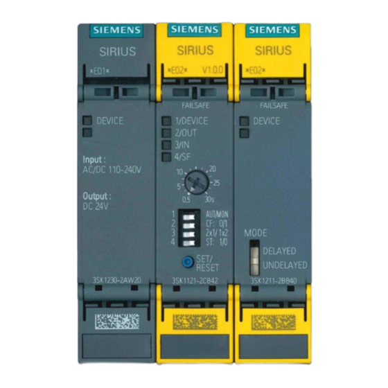
Page 75: Connection Circuit Diagrams For The Switching Devices
Connection circuit diagrams for the switching devices 3SK1230-2AW20 power supply ① Top cover ② Top cover; inner labeling ③ LEDs ④ Bottom cover ⑤ Bottom cover; inner labeling ⑥ Data matrix code ⑦ Device identification label Application document for functional safety STO, SS1 (ISO 13849-1) Compact User Manual, 09/2016, A5E34871844AM... - Page 76 Connection circuit diagrams for the switching devices 3SK1121-2CB4x basic device advanced ① Top cover ② Top cover; inner labeling ③ LEDs ④ Sets the delay time ⑤ DIP switch ⑥ SET/reset button ⑦ Bottom cover ⑧ Bottom cover; inner labeling ➈...
- Page 77 Connection circuit diagrams for the switching devices 3SK1211-2BB40 output expansion ① Top cover ② Top cover; inner labeling ③ LEDs ④ Shift switch ⑤ Bottom cover ⑥ Bottom cover; inner labeling ⑦ Data matrix code ⑧ Device identification label Application document for functional safety STO, SS1 (ISO 13849-1) Compact User Manual, 09/2016, A5E34871844AM...
- Page 78 Connection circuit diagrams for the switching devices Coupling relay PSR-SPP- 24DC/FSP/1X1/1X2 - 2981981 (Phoenix Contact) Application document for functional safety STO, SS1 (ISO 13849-1) Compact User Manual, 09/2016, A5E34871844AM...
- Page 79 Connection circuit diagrams for the switching devices Relay module - PR1-RSC3-LDP-24DC/2X21AU - 2834520 (Phoenix Contact) ① Relay socket PR1 / PR2 ② Relay holding bar with ejector function and surface for labeling 7.5 × 15 mm (PR1...)/ 8 × 28 mm (PR2...) ③...
- Page 80 Connection circuit diagrams for the switching devices Application document for functional safety STO, SS1 (ISO 13849-1) Compact User Manual, 09/2016, A5E34871844AM...
-
Page 81: Recommended Circuit Breakers And Power Contactors
Recommended circuit breakers and power contactors Article number Manufacturer Type Armature circuit 3RT2015-2AP02 Siemens Power contactor 3RT2916-1BD00 Siemens Power contactor 3RT1926-1BD00 Siemens Power contactor 3RT2023-2AL20 Siemens Power contactor 3RT2926-1BD00 Siemens Power contactor 3RT1035-3AL20 Siemens Power contactor 3RT1936-4EA2 Siemens Power contactor... - Page 82 Recommended circuit breakers and power contactors Application document for functional safety STO, SS1 (ISO 13849-1) Compact User Manual, 09/2016, A5E34871844AM...
Need help?
Do you have a question about the SINAMICS DCM and is the answer not in the manual?
Questions and answers