
Related Manuals for YASKAWA JEPMC-MP2300-Y Series


Summary of Contents for YASKAWA JEPMC-MP2300-Y Series
- Page 1 MP2300 Machine Controller Basic Module User’s Manual Model Number: JEPMC-MP2300-Y...
- Page 2 Yaskawa. No patent liability is assumed with respect to the use of the information contained herein. Moreover, because Yaskawa is con- stantly striving to improve its high-quality products, the information contained in this manual is subject to change without notice.
- Page 3 Using this Manual The MP2300 is a compact Machine Controller that contains the power supply, the CPU, I/O, and the communication functions in one single unit. Please read this manual to ensure correct usage of the MP2300 system. Keep this manual in a safe place for future reference.
- Page 4 ■ Graphic Symbols Used in this Manual The graphic symbols used in this manual indicate the following type of information. This symbol is used to indicate important information that should be memorized or minor precautions, such as precautions that will result in alarms if not heeded. ■...
- Page 5 Manual Name Manual Number Contents Σ-III Series SGM S/SGDS Describes the models, specifications, wiring, trial SIEP S800000 11 operation, adjustment, function application meth- MECHATROLINK-II ods, maintenance, inspection, and MECHA- SERVOPACKs with Communication User’s TROLINK communication of the Σ-III Series Manual SERVOPACKs and Servomotors.
- Page 6 Safety Precautions The following precautions are for checking products on delivery, storage, transportation, installation, wiring, operation, application, inspection, and disposal. These precautions are important and must be observed. ■ General Precautions WARNING • Before connecting the machine and starting operation, ensure that an emergency stop procedure has been provided and is working correctly.
- Page 7 Storage and Transportation CAUTION • Do not store or install the MP2300 in the following locations. There is a risk of fire, electrical shock, or device damage. • Direct sunlight • Ambient temperature exceeds the storage or operating conditions • Ambient humidity exceeds the storage or operating conditions •...
- Page 8 Wiring CAUTION • Check the wiring to be sure it has been performed correctly. There is a risk of motor run-away, injury, or an accident. • Always use a power supply of the specified voltage. There is a risk of burning. •...
- Page 9 Maintenance and Inspection Precautions CAUTION • Do not attempt to disassemble the MP2300. There is a risk of electrical shock or injury. • Do not change wiring while power is being supplied. There is a risk of electrical shock or injury. •...
- Page 11 Variable Tables System Variable Table (Tree View) The following table lists details on the system variables provided by MPE720 version 6. Variable Name Register Comments OnCoil SB000004 Always ON Clock Calendar DayOfWeek SW00019 Calendar:Day of week HoursMinutes SW00017 Calendar:Hours Minutes MonthDate SW00016 Calendar:Month Day...
- Page 12 (continued) Variable Name Register Comments ErrorInterrupt Interrupt Program Error Code SW00083 Interrupt Program Error Code Count SW00082 Interrupt Program Error Count ProgramNumber SW00138 Error Program Number ReferProgramNumber SW00139 Function Program Number ReferStep SW00140 Function Program Step Number ErrorIO I/O Error Count SW00200 I/O Error Count...
- Page 13 (continued) Variable Name Register Comments LowScan Low Scan Relay FirstScanRunning SB000003 After Low Scan Start,Only 1 Scan ON OnAfter Start-up Relay FiveSecond SB00003A After 5.0s,Scan Start-up Relay OneSecond SB000038 After 1.0s,Scan Start-up Relay TwoSecond SB000039 After 2.0s,Scan Start-up Relay PulseEvery Sampling Relay HalfSecond SB000034...
- Page 14 System Variables (Sorted by Register) Register Variable Name Comments SB000001 HighScan.FirstScanRunning After High Scan Start,Only 1 Scan ON SB000003 LowScan.FirstScanRunning After Low Scan Start,Only 1 Scan ON SB000004 OnCoil Always ON SB000010 HighScan.SquareWave.OneScan 1 Scan Flicker Relay SB000011 HighScan.SquareWave.HalfSecond 0.5s Flicker Relay SB000012 HighScan.SquareWave.OneSecond 1.0s Flicker Relay...
- Page 15 (continued) Register Variable Name Comments Running Stop Require SB00040E CPU.Status.Stopped (From EWS:1=STOP,0=RUN) SB00040F CPU.Status.RunSwitch RUN switch status at power is on (1=RUN,0=STOP) SB000410 CPU.Error.Failure Important Failure SB000413 CPU.Error.Exception Exception Error SB000418 CPU.Error.ProgramError User Calculation Error SB000419 CPU.Error.IOError I/O Error SW00044 ScanTime.High.ExceededCount High Scan Over Counter SW00046...
- Page 16 Axis Motion Parameters (Tree View) The following table lists the axismotion parameters registered for each logical axis. Register address IW (IB/IL/IF/IA) xx00 indicates the leading input register address +00. Register address OW (OB/OL/OF/OA) xx00 indicates the leading output register address +00. Variable Name Register Comments...
- Page 17 (continued) Variable Name Register Comments Command Command Abort OBxx091 Abort command Busy IBxx090 Servo command busy Complete IBxx098 Servo command complete Fail IBxx093 Servo command failed GetValue IWxx08 Servo command response Hold IBxx091 Servo command holding JogRelativeMoveDirection OBxx092 Selects Jog or Step direction. Pause OBxx090 Pause command...
- Page 18 (continued) Variable Name Register Comments Gain Gain IntegralClear OBxx00B Resets position loop integral value. PhaseFeedForward OWxx31 Add to the speed in 0.01% Feed Forward adds to the position to increase PositionFeedForward OWxx30 response PositionIntegration OWxx32 Time in ms used to integrate the position error PositionLoop OWxx2E Increase value for more rigid control.
- Page 19 (continued) Variable Name Register Comments Latch Latch Complete IBxx0C2 Latch complete (LCOMP) CompleteN IBxx2CA Servo status L_CMP Enable OBxx004 Sets bit to activate latch trigger. Value ILxx18 Latch position (LPOS) WindowEnable OBxx094 Enables the latch zone. WindowLowerLimit OLxx2A The lower limit of the latch window WindowUpperLimit OLxx2C The upper limit of the latch window...
- Page 20 (continued) Variable Name Register Comments Position Position Loads current position with ABS encoder position at AbsDataRestore OBxx007 last power off. AbsDataRestored IBxx0C8 Absolute data has been restored (ABSLDE). Actual ILxx16 Actual (feedback) position (APOS) Commanded position, incremental or absolute based Commanded OLxx1C on MoveType...
- Page 21 (continued) Variable Name Register Comments ServoParameter2 ServoParameter2 GetNumber IWxx37 Second requested parameter number (Pn) GetValue ILxx3A Second requested parameter value The number of the second amplifier parameter to be SetNumber OWxx54 read or set SetSize OWxx55 The size of the second amplifier parameter data SetValue OLxx56 The value to be set for the second amplifier parameter...
- Page 22 Axis Motion Parameters (Sorted by Register) Register Variable Name Comments IWxx00 MonitorMask Drive status mask IBxx000 Monitor.PowerUp SeqDone Motion controller ready IBxx001 Monitor.ServoOn Servo is energized. IBxx002 Monitor.ServoBusy System is busy. IBxx003 Monitor.ServoReady Servo is ready. IWxx01 Alarm.OutOfRangeParameter Parameter number that is over range ILxx02 Warning.AllMask Warning mask...
- Page 23 (continued) Register Variable Name Comments IBxx0B8 Command2.Complete Servo Command2 complete IWxx0C StatusMask Status mask IBxx0C0 Position.ProfilerComplete Profiler complete (DEN) IBxx0C1 Position.InPosition In position (POSCOMP) IBxx0C2 Latch.Complete Latch complete (LCOMP) IBxx0C3 Position.InPosition2 Second in position (NEAR) IBxx0C4 Home.AtHome At home position (ZERO) IBxx0C5 Home.Complete Home complete...
- Page 24 (continued) Register Variable Name Comments IBxx2EE IO.IO14 Servo I_O IO14 IBxx2EF IO.IO15 Servo I_O IO15 IWxx2F Monitor.TypeResponse Servo monitor information ILxx30 Monitor.Monitor2Value Monitor2 ILxx32 Monitor.Monitor3Value Monitor3 ILxx34 Monitor.Monitor4Value Monitor4 ILxx38 ServoParameter.GetValue Requested parameter value IWxx36 ServoParameter.GetNumber Requested parameter number (Pn) IWxx37 ServoParameter2.GetNumber Second requested parameter number (Pn)
- Page 25 (continued) Register Variable Name Comments OWxx0E Torque.SpeedLimit Maximum speed allowed during torque control OWxx09 CommandMask Servo Command options OBxx090 Command.Pause Pause command OBxx091 Command.Abort Abort command OBxx092 Command.JogRelativeMoveDirection Selects Jog or Step direction. OBxx093 Home.Direction Selects home direction. OBxx094 Latch.WindowEnable Enables the latch zone.
- Page 26 (continued) Register Variable Name Comments Selects which value will be returned from the servopack. Bits 4 to 7 set OWxx4E Monitor.Type monitor2and bits C to F set monitor4 OWxx4F Alarm.MonitorNumber This value determines which of the last 10 alarm codes are returned. OWxx50 ServoParameter.SetNumber The number of the amplifier parameter to be read or set...
- Page 27 Contents Using this Manual - - - - - - - - - - - - - - - - - - - - - - - - - - - - - - - - - - - - - - - - - - - - - - - - - - - - - - - iii Safety Information - - - - - - - - - - - - - - - - - - - - - - - - - - - - - - - - - - - - - - - - - - - - - - - - - - - - - - - -v Safety Precautions- - - - - - - - - - - - - - - - - - - - - - - - - - - - - - - - - - - - - - - - - - - - - - - - - - - - - - - vi Variable Tables - - - - - - - - - - - - - - - - - - - - - - - - - - - - - - - - - - - - - - - - - - - - - - - - - - - - - - - - - xi...
- Page 28 3 Module Specifications 3.1 General Specifications - - - - - - - - - - - - - - - - - - - - - - - - - - - - - - - - - - - - - - - - - 3-2 3.1.1 Environmental Conditions - - - - - - - - - - - - - - - - - - - - - - - - - - - - - - - - - - - - - - - - - - - - - - - - 3-2 3.1.2 Function Lists - - - - - - - - - - - - - - - - - - - - - - - - - - - - - - - - - - - - - - - - - - - - - - - - - - - - - - - - - 3-3 3.2 Basic Module- - - - - - - - - - - - - - - - - - - - - - - - - - - - - - - - - - - - - - - - - - - - - - - - 3-6...
- Page 29 4.4 I/O Module (Optional) Connections - - - - - - - - - - - - - - - - - - - - - - - - - - - - - - - 4-27 4.4.1 LIO-01/LIO-02 Modules - - - - - - - - - - - - - - - - - - - - - - - - - - - - - - - - - - - - - - - - - - - - - - - - - 4-27 4.4.2 LIO-04/LIO-05 Module Connections- - - - - - - - - - - - - - - - - - - - - - - - - - - - - - - - - - - - - - - - - 4-34 4.4.3 DO-01 Module Connections - - - - - - - - - - - - - - - - - - - - - - - - - - - - - - - - - - - - - - - - - - - - - - 4-46 4.4.4 AI-01 Module Connections - - - - - - - - - - - - - - - - - - - - - - - - - - - - - - - - - - - - - - - - - - - - - - - 4-53...
- Page 30 5.5.8 217IF-01 Modules - - - - - - - - - - - - - - - - - - - - - - - - - - - - - - - - - - - - - - - - - - - - - - - - - - - - - 5-39 5.5.9 260IF-01 Modules - - - - - - - - - - - - - - - - - - - - - - - - - - - - - - - - - - - - - - - - - - - - - - - - - - - - - 5-41 5.5.10 261IF-01 Modules - - - - - - - - - - - - - - - - - - - - - - - - - - - - - - - - - - - - - - - - - - - - - - - - - - - - 5-42 5.5.11 Examples of Register Allocation by Self-configuration - - - - - - - - - - - - - - - - - - - - - - - - - - - 5-43...
- Page 31 7.2.11 Change Filter Time Constant (SCC) - - - - - - - - - - - - - - - - - - - - - - - - - - - - - - - - - - - - - - - - 7-58 7.2.12 Change Filter Type (CHG_FILTER) - - - - - - - - - - - - - - - - - - - - - - - - - - - - - - - - - - - - - - - - 7-60 7.2.13 Change Speed Loop Gain (KVS) - - - - - - - - - - - - - - - - - - - - - - - - - - - - - - - - - - - - - - - - - - 7-62 7.2.14 Change Position Loop Gain (KPS)- - - - - - - - - - - - - - - - - - - - - - - - - - - - - - - - - - - - - - - - - 7-64...
- Page 32 9.1.2 Reading Absolute Data - - - - - - - - - - - - - - - - - - - - - - - - - - - - - - - - - - - - - - - - - - - - - - - - - - 9-3 9.1.3 Finite Length/Infinite Length Axes and Absolute Position Detection - - - - - - - - - - - - - - - - - - - 9-4 9.2 Setting Procedure of Absolute Position Detection Function - - - - - - - - - - - - - - - 9-5 9.2.1 System Startup Flowchart - - - - - - - - - - - - - - - - - - - - - - - - - - - - - - - - - - - - - - - - - - - - - - - - 9-5...
- Page 33 11.1.4 Parameters Updated when a Motion Command Is Executed (Regardless of User Constants Self-Writing Function Setting and MECHATROLINK Connection) - - - - - - - - - - - - - - - - - - - - - - - - - - - - - - - - - - - - - - - - - - - - 11-4 11.1.5 Parameters Updated during Self-configuration - - - - - - - - - - - - - - - - - - - - - - - - - - - - - - - - 11-5 11.2 Precautions When Setting or Changing User Definition Files and Scan Times 11-7 11.2.1 Setting or Changing User Definition Files - - - - - - - - - - - - - - - - - - - - - - - - - - - - - - - - - - - - 11-7...
- Page 34 Appendix B B System Registers Lists - - - - - - - - - - - - - - - - - - - - - - - - - - - - - - - - - - - - - - - - - - B-2 B.1 System Service Registers - - - - - - - - - - - - - - - - - - - - - - - - - - - - - - - - - - - - - - - - - - - - - - - - - B-2 B.2 Scan Execution Status and Calendar- - - - - - - - - - - - - - - - - - - - - - - - - - - - - - - - - - - - - - - - - - B-4 B.3 Program Software Numbers and Remaining Program Memory Capacity Name - - - - - - - - - - - - B-4...
-
Page 35: Table Of Contents
Overview of the MP2300 This chapter explains an overview and features of the MP2300 Machine Controller. 1.1 Features .................. 1-2 1.2 MP2300 Configuration ............. 1-3 1.2.1 Basic Module Appearance ..............1-3 1.2.2 MP2300 Modules ................... 1-4 1.2.3 MP2300 Series Models ................. 1-4 1.3 System Configuration .............. -
Page 36: Features
1 Overview of the MP2300 1.1 Features The MP2300 is an all-in-one, compact Machine Controller that combines power supply, CPU, SVB, I/O, and communication functions in one system. The MP2300 consists of a Basic Module that performs motion control and sequence control and Optional Modules that perform I/O and communication functions. -
Page 37: Mp2300 Configuration
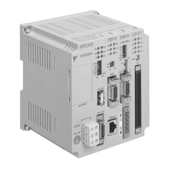
The MP2300 is configured with one Basic Module and up to three Optional Modules. 1.2.1 Basic Module Appearance The following figure shows the external appearance of the Basic Module. LED indicators MP2300 Switches YASKAWA Battery holder STOP INIT CNFG MECHATROLINK... -
Page 38: Mp2300 Modules
1 Overview of the MP2300 1.2.2 MP2300 Modules 1.2.2 MP2300 Modules The following table shows the names and descriptions of the Basic Module and Optional Modules. Group Name Description Model Remarks MECHATROLINK-I, Basic Module Basic Module MP2300 JAPMC-MP2300 MECHATROLINK-II 8 input, 4 outputs MECHATROLINK-II SVB-01 JAPMC-MC2310... - Page 39 1.2 MP2300 Configuration (cont’d) Model Combination of Modules Reserved Basic Module JEPMC-MP2300-Y4 Basic Module JEPMC-MP2300-Y5 Reserved Basic Module JEPMC-MP2300-Y7 Basic Module JEPMC-MP2300-Y8 Reserved Basic Module JEPMC-MP2300-Y10 Basic Module JEPMC-MP2300-Y11...
-
Page 40: System Configuration
For the details on the system configuration example, refer to 2.1.2 System Configuration on page 2-3. Use the connecting cables and connectors recommended by Yaskawa. Always check the device to be used and select the correct cable for the device. -
Page 41: Devices Connectable To Mechatrolink
1.4 Devices Connectable to MECHATROLINK 1.4 Devices Connectable to MECHATROLINK The devices that are compatible with MECHATROLINK and can be connected to the MP2300 and the SVB-01 Module are listed below. 1.4.1 SERVOPACKs Model Number Details MECHATROLINK-I MECHATROLINK-II SGDS- SGDS SERVOPACK SGDH- SGDH SERVOPACK JUSP-NS115... -
Page 42: Cables And Accessories
1 Overview of the MP2300 1.5.1 Cables 1.5 Cables and Accessories 1.5.1 Cables The following table shows the cables that can be connected to the MP2300 Basic Module and Optional Modules. Connector Module Application Model Specifications Name Used between CPU I/O External I/O JEPMC-W2060- CPU I/O and External I/O... -
Page 43: Accessories And Options
1.5 Cables and Accessories 1.5.2 Accessories and Options Name Accessory/Optional Model Remarks ER3VC + exclusive use connector Battery Accessory JZSP-BA01 (BA000517) Power Supply Connector Accessory 721-203/026 Cable side DIN Rail Mounting Parts Optional JEPMC-OP300 2 parts for 1 set Option Slot Cover Optional JEPMC-OP2300 Front cover for empty slot... - Page 44 1 Overview of the MP2300 MEMO 1-10...
- Page 45 System Startup and Sample Programs This chapter describes the procedure for starting the MP2300 system and sample programs for typical operation and control. 2.1 Model System Startup Procedure ..........2-2 2.1.1 Flowchart for Model System Startup ............2-2 2.1.2 System Configuration ................2-3 2.1.3 Initializing SERVOPACKs ..............
-
Page 46: Model System Startup Procedure
2 System Startup and Sample Programs 2.1.1 Flowchart for Model System Startup 2.1 Model System Startup Procedure This section describes the procedure for starting the Model System and using the sample programs of the MPE720 Programming Tool (on the MPE720 installation disk). The procedure for designing machine systems is omitted here. -
Page 47: System Configuration
This section describes the system configuration shown in the following diagram. Prepare each devices and connect as diagram. 24 VDC MECHATROLINK cable (see (1).) power (see (4).) SERVOPACK (see (3).) SERVOPACK (see (3).) 200V 200V YASKAWA SERVOPACK YASKAWA SERVOPACK 218IF-01 MP2300 SGDS-01A12A SGDS-01A12A Terminator YASKAWA STRX MECHATROLINK (see (1).) -
Page 48: Initializing Servopacks
2 System Startup and Sample Programs 2.1.3 Initializing SERVOPACKs ( 2 ) Programming Device-related Equipment Name Model Quantity MPE720 CPMC-MPE720 version 4.41A or later PP Cable (for RS-232C connection) JEPMC-W5311-03 PP Cable (for Ethernet connection) Commercially-available cross cable Computer Commercially-available product Above equipments can connect to the MP2300 with either RS-232C or Ethernet. -
Page 49: Mp2300 Self-Configuration
2.1 Model System Startup Procedure Press the Key on the Digital Operator to display the Auxiliary Function Mode main menu, and use the Keys to select Fn005. Press the Key to switch to the Fn005 parameter initialization execution display. * If the display does not change and “NO-OP” is displayed on the status display, a Write Prohibited password has been set using Fn010 and the user settings cannot be initialized. - Page 50 2 System Startup and Sample Programs 2.1.4 MP2300 Self-configuration Turn ON the INIT and CNFG switches on the DIP switch (SW1) on the MP2300 Basic Module. STOP INIT CNFG TEST Turn ON the 24-VDC power supply to the MP2300. Check that the LED indicators on the MP2300 Basic Module change as the following illustration.
-
Page 51: Starting And Preparing Mpe720
2.1 Model System Startup Procedure 2.1.5 Starting and Preparing MPE720 This section describes the preparation for connecting the MPE720 (motion programming software, optional) to the MP2300 and the method for installing the sample program for the MP2300. The explanation is given assuming that the MPE720 has been installed on your personal computer. Refer to Machine Controller MP900/MP2000 Series MPE720 Software for Programming Device User’s Manual (Manual No. - Page 52 2 System Startup and Sample Programs 2.1.5 Starting and Preparing MPE720 ( 1 ) Starting the MPE720 Start the MPE720 using the following procedure. Open the YE_Applications Folder and double-click the MPE720 icon. Or, select Start - All Programs - YE_Application - MPE720. The operation to start the MPE720 depends on the OS version number of the personal computer.
- Page 53 2.1 Model System Startup Procedure ( 2 ) Setting and Saving Communication Process Make communication settings for connecting the MPE720 and the MP2300 using the following procedure. These settings are not required if the communication settings have already been made. When the MPE720 is started, the Communication Process icon will be displayed on the task tray at the right bottom of the screen.
- Page 54 2 System Startup and Sample Programs 2.1.5 Starting and Preparing MPE720 Match the settings under Physical Port to the computer’s serial communication port. Leave the other items on the default settings. Once the settings have been completed and checked, click the OK Button to close the Logical Port Setting Dialog Box. The Logical Port Setting Window appears.
- Page 55 2.1 Model System Startup Procedure Click Connection Tab to display the page. Click LAN settings. The Local Area Network (LAN) Settings Dialog Box appears. Check if the Automatically detect the settings check box is cleared and click the OK Button to close the dialog box. For a computer running Windows 2000 OS, click the Start Button and select Settings - Control Panel - Network and dial-up connection (N).
- Page 56 2 System Startup and Sample Programs 2.1.5 Starting and Preparing MPE720 For the computer running Windows 2000 OS, double-click the Local area connection icon. For the computer running Windows XP OS, select Local area connection and click Change the settings of connection in the Network Task field. <...
- Page 57 2.1 Model System Startup Procedure Click the Using the following IP address Option Button and enter 192 168 1 2 under IP Address and 255 255 255 0 under Subnet Mask. Click the OK Button to close the dialog box. Double-click Logical Port No.
- Page 58 2 System Startup and Sample Programs 2.1.5 Starting and Preparing MPE720 Enter the IP address of computer and click OFF for Default. Leave the other items on their default settings. Click the OK Button to close the dialog box. Click the OK Button in the Logical Port Setting Dialog Box to return to the Communi- cation Process Window.
- Page 59 2.1 Model System Startup Procedure cess Window. Double-click the Communication Manager icon in the YE_Application Folder to reopen the Communication Process Window. Double-click ( 3 ) Creating Group Folders (Option) In the File Manager Window, create a group folder for storing order folders. Refer to Group Folders, Order Folders, Controller folders at the bottom of this page for more information about these folders.
- Page 60 2 System Startup and Sample Programs 2.1.5 Starting and Preparing MPE720 Enter a group folder name of up to 8 characters and click the OK Button. A new group folder will be created. Double-click (root) or click to display the entered group folder name.
- Page 61 2.1 Model System Startup Procedure Enter an Order Folder name of up to 8 characters and click the OK Button. A new Order Folder will be created. Click the group folder or to display the entered Order Folder name. ( 5 ) Creating Controller Folders (Required) In the File Manager Window, create a Controller Folder for storing programs.
- Page 62 2 System Startup and Sample Programs 2.1.5 Starting and Preparing MPE720 2-18...
-
Page 63: Reading Sample Programs And Setting And Saving Parameters
2.1 Model System Startup Procedure 2.1.6 Reading Sample Programs and Setting and Saving Parameters This section use sample programs to explain how to log on after being connected to the MP2300, transfer programs, set motion fixed parameters, and log off. The following flowchart outlines the order of the explanations. - Page 64 2 System Startup and Sample Programs 2.1.6 Reading Sample Programs and Setting and Saving Parameters performed when using MPE720. If a Cannot change to CPU while logged on message is displayed when Online is selected, refer to 2.1.6 ( 9 ) Logging Off on page 2-35 and log off from the Controller folder.
- Page 65 2.1 Model System Startup Procedure < For RS-232C Connection > Leave the values other than the Logical Port No on their default settings, and click OK Button. <For Ethernet Connection > Enter the IP address of the personal computer, and click OK Button. Click the Yes Button in the dialog box that is displayed next to complete selection of the logical port.
- Page 66 2 System Startup and Sample Programs 2.1.6 Reading Sample Programs and Setting and Saving Parameters Logging On Online When using MPE720, logging on is performed for each Controller Folder. Controller Folders that have not been logged onto cannot use the MPE720 functions. Right-click on the Controller Folder that was selected in step 1 and select Log On from the pop-up menu that is displayed.
- Page 67 2.1 Model System Startup Procedure ( 2 ) Loading the Sample Programs The sample programs on the MPE720 system CD-ROM will be decompressed on the personal com- puter and loaded to the Controller Folder. Set the MPE720 system CD-ROM in the CD-ROM drive of the personal computer.
- Page 68 2 System Startup and Sample Programs 2.1.6 Reading Sample Programs and Setting and Saving Parameters Deselect Compression transmission. Check the Destination. If the Destination is different to the unpack destination folder, click the Change Button and continue to step 5. If the Destination is correct, move to step 6.
- Page 69 2.1 Model System Startup Procedure The All Media to MPE720 Window will appear. Select File - Exit to end reading files to the MPE720. ( 3 ) Transfer Individual Programs Transfer the programs that have been read to the MPE720 individually to the MP2300. Right-click on the Controller Folder that has been logged onto online and select Transfer - Selected Files - From MPE720 to Controller from the pop-up menu that is displayed.
- Page 70 2 System Startup and Sample Programs 2.1.6 Reading Sample Programs and Setting and Saving Parameters Select the programs to be transferred. For programs with a Details Button next to them, click the Details Button and select the individual function programs for the program listed in the Set Details Dialog Box that is displayed.
- Page 71 2.1 Model System Startup Procedure b) Motion Main Program Detail Set Dialog Box The details for the Motion Main Program of sample program are shown below. In this example, select Select All and click the OK Button to return to the Individual Load Window.
- Page 72 2 System Startup and Sample Programs 2.1.6 Reading Sample Programs and Setting and Saving Parameters ( 4 ) Set and Save Motion Fixed Parameters This section describes the procedure for setting motion fixed parameters for axes 1 and 2 to match the sample program .
- Page 73 2.1 Model System Startup Procedure Set the fixed parameters for axis 1. Select Axis 1 from the axis selection box at the top-left of the window and select mm under No. 4 Reference unit selection on the Fixed Parameter Tab Page. In the Engineering Manager Window, select File (F) - Save (S) to save the settings for axis 1 fixed parameters.
- Page 74 2 System Startup and Sample Programs 2.1.6 Reading Sample Programs and Setting and Saving Parameters ( 5 ) Making Servo Adjustments and Saving SERVOPACK Parameters This section describes how to make Servo adjustments and save the SERVOPACK parameters for each axis to the MP2300. Execute servo gain and other adjustments for each Servo.
- Page 75 2.1 Model System Startup Procedure Select File (F) - Save (S) to save the SERVOPACK settings for axis 1 to the MP2300. Refer to steps 2 to 5 to write and save the SERVOPACK current position for axis 2 as settings data, using the same procedure as for axis 1.
- Page 76 2 System Startup and Sample Programs 2.1.6 Reading Sample Programs and Setting and Saving Parameters Select File - Execute. Click the Yes Button in the displayed confirmation dialog box, and then click the Yes Button in the TrnSys Dialog Box that is displayed. Another confirmation dialog box will be displayed.
- Page 77 2.1 Model System Startup Procedure ( 7 ) Dumping All Data Execute All Program File Dump to back up to a personal computer the module configuration defini- tions automatically detected by the MP2300 during self-configuration and edited programs. The MP2300 program data and the program data in the personal computer hard disk are synchronized when all programs are dumped.
- Page 78 2 System Startup and Sample Programs 2.1.6 Reading Sample Programs and Setting and Saving Parameters Select File - Exit to stop the dumping of all data. ( 8 ) CPU RUN Settings If the CPU STOP status is not cleared after executing processes such as saving to flash memory, use the following procedure to return to RUN status.
- Page 79 2.1 Model System Startup Procedure Change confirmation dialog box will be displayed. Click the Yes Button to return to the Controller Running Status Dialog Box. Check that the RUN LED indicator is lit. Click the CLOSE Button in the Controller Running Status Dialog Box to exit RUN settings.
-
Page 80: Checking Sample Program Operation
2 System Startup and Sample Programs 2.2.1 Operation Check 1: Manual Operation 2.2 Checking Sample Program Operation This section describes how to check three operations in the model system by using the Tuning Panel Window for sample programs. 2.2.1 Operation Check 1: Manual Operation ( 1 ) Program Outline This section describes how to execute JOG and STEP operations for Servomotor 1 or 2 (axis 1 or 2) using a ladder program such as the one shown below. - Page 81 2.2 Checking Sample Program Operation ( 2 ) Displaying the H02 Drawing Tuning Panel Use the following procedure to display the H02 Drawing Tuning Panel. Log on online, open the Programs folder, and then open the High Scan Programs folder in the PLC folder where the sample programs are saved in the File Manager Window.
- Page 82 2 System Startup and Sample Programs 2.2.1 Operation Check 1: Manual Operation ( 3 ) Procedure Use the following procedure to confirm operation. Servo ON Start JOG or STEP operation. Confirm operation. The following table gives an outline of the operation when the Tuning Panel window is used. Current Value Data Name Operation Outline...
- Page 83 2.2 Checking Sample Program Operation ( 4 ) Sample Program Details [ a ] H Drawing The H parent drawing controls the overall sample program. Main Program: High-speed Main Program High-speed main program Servo ON and Alarm reset Servo ON, alarm reset Name H01 JOG and STEP JOG, STEP...
- Page 84 2 System Startup and Sample Programs 2.2.1 Operation Check 1: Manual Operation H01 Drawing - (2) ########## Speed Unit and Acceleration/Deceleration Unit Selection ########## Bits 0 to 3: Speed Unit Selection (0: Reference unit/s; 1: Reference unit/min.; 2: Percentage) Bits 4 to 7: Acceleration/Deceleration Unit Selection (0: Reference unit/s; 1: ms) Axis 1 Function Settings 1 (unit) Axis 1 Function Settings 1 work 0006...
- Page 85 2.2 Checking Sample Program Operation [ d ] H02.01 Drawing The H02.01 grandchild drawing controls JOG and STEP operation for axis 1. ##########Axis 1 Manual operation (JOG and STEP)########## ##########JOG########## Axis 1 JOG Axis 1 jog command Axis 1 forward jog Axis 1 reverse jog Axis 1 SV_ON DB000000...
- Page 86 2 System Startup and Sample Programs 2.2.1 Operation Check 1: Manual Operation [ e ] H02.02 Drawing The H02.02 grandchild drawing controls JOG and STEP operation for axis 2. ##########Axis 2 Manual operation (JOG and STEP)########## ##########JOG########## Axis 2 JOG Axis 2 forward jog Axis 2 reverse jog Axis 2 SV_ON...
-
Page 87: Operation Check 2: Position Control
2.2 Checking Sample Program Operation 2.2.2 Operation Check 2: Position Control ( 1 ) Operation Outline In this example, an X-Y plotter like the one shown in the figure is operated by ladder and motion pro- grams. Servomotor X-Y plotter ( 2 ) Program Outline A ladder program (H04 Drawing) and three prepared sample programs (MPM001, MPM002, and MPM003) are used to check the operation, as shown in the figure. - Page 88 2 System Startup and Sample Programs 2.2.2 Operation Check 2: Position Control ( 3 ) Display Tuning Panel for H04 Drawing Use the same procedure as the H04 Drawing in the High Scan 2.2.1 ( 2 ). Right-click Programs folder in the File Manager Window and select Open - Tuning Panel from the pop-up menu that is displayed.
- Page 89 2.2 Checking Sample Program Operation ( 4 ) Procedure Use the following procedure to operate the Tuning Panel and check operation. Servo ON Change the Servo ON PB current value from OFF to ON. The Servomotor will turn ON and the Servo will be clamped. Motion program No.
- Page 90 2 System Startup and Sample Programs 2.2.2 Operation Check 2: Position Control ( 5 ) Sample Program Details [ a ] H04 Drawing The H04 child drawing contains the ladder program for managing and controlling MPM motion pro- grams. Positioning Main Processing ########## 位置決め動作メイン処理 ########## ########## モーションプログラム起動シーケンス...
- Page 91 2.2 Checking Sample Program Operation [ b ] Motion Program MPM001 The MPM001 motion program uses the Servomotor phase-C pulse to perform home return. 00001 "MPM001"; 00002 OW803C=3; "X axis home return method selection (3: Phase C)" 00003 OW80BC=3; "Y axis home return type selection (3: Phase C)" 00004 VEL [X]1000 [Y]1000;...
-
Page 92: Operation Check 3: Phase Control - Electronic Shaft
2 System Startup and Sample Programs 2.2.3 Operation Check 3: Phase Control - Electronic Shaft 2.2.3 Operation Check 3: Phase Control - Electronic Shaft ( 1 ) Machine Outline As shown in the following figure, the Servomotor performs the same operation as rolls No. 1 and No. 2 connected to the line shaft. - Page 93 2.2 Checking Sample Program Operation ( 3 ) Display Tuning Panel for H06 Drawing Use the same procedure as . Right-click the H06 Drawing in the High Scan 2.2.1 ( 2 ) Programs folder in the File Manager Window and select Open - Tuning Panel from the pop-up menu that is displayed.
- Page 94 2 System Startup and Sample Programs 2.2.3 Operation Check 3: Phase Control - Electronic Shaft ( 4 ) Procedure Use the following procedure to operate the Tuning Panel and check operation. Servo ON Change the Servo ON PB current value from OFF to ON. The Servomotor will turn ON and the Servo will be clamped.
- Page 95 2.2 Checking Sample Program Operation H06.01 Drawing - (2) Motion command 0 (NOP) setting Electronic shaft stop Axis 1 motion command DB000002 0005 STORE 0017 Source 00000 NL-1 Dest OW8008 Electronic shaft stop DB000002 Axis 2 motion command 0006 STORE 0019 Source 00000 NL-1...
-
Page 96: Operation Check 4: Phase Control - Electronic Cam
2 System Startup and Sample Programs 2.2.4 Operation Check 4: Phase Control - Electronic Cam 2.2.4 Operation Check 4: Phase Control - Electronic Cam ( 1 ) Machine Outline As shown in the following figure, the Servomotor performs the same operation as the mechanical cam synchronized to a roller connected to the line shaft. - Page 97 2.2 Checking Sample Program Operation ( 3 ) Display Tuning Panel for H06 Drawing Use the same procedure as . Right-click the H06 Drawing in the High Scan 2.2.1 ( 2 ) Programs folder in the File Manager Window and select Open - Tuning Panel from the pop-up menu that is displayed.
- Page 98 2 System Startup and Sample Programs 2.2.4 Operation Check 4: Phase Control - Electronic Cam ( 4 ) Procedure Servo ON Change the Servo ON PB current value from OFF to ON. The Servomotor will turn ON and the Servo will be clamped. Enter Cam Data Enter any value within the setting range to Cam axis: amplitude setting (double amplitude) and Cam axis: main axis moving amount per cycle.
- Page 99 2.2 Checking Sample Program Operation ( 5 ) Sample Program Details [ a ] H06.02 Drawing The H06.02 grandchild drawing controls phase control (electronic cam) operation. H06.02 Drawing - (1) P00121 H06.02 Main Program: Phase Control 2 (Electronic Cam) ########## Phase Control 2 (Electronic Cam) ########## ########## Description ########## Axis 1: Master axis = Phase control (electronic shaft)
- Page 100 2 System Startup and Sample Programs 2.2.4 Operation Check 4: Phase Control - Electronic Cam H06.02 Drawing - (2) P00122 H06.02 Main Program: Phase Control 2 (Electronic Cam) Operation command DB000000 Linear accelerator/decelerator input 0010 STORE 0028 Source 0.000000E+000 NL-1 Dest DF00012 Linear accelerator/decelerator input 0011...
- Page 101 2.2 Checking Sample Program Operation H06.02 Drawing - (3) Main Program Phase Control 2 (Electronic Shaft) P00123 H06.02 メインプログラム 位置制御2(電子カム)処理 Detection in forward direction 正方向検出 Electronic cam phase 電子カム位相 DB000008 0020 SUBX 0043 SourceA DL00066 NL-1 SourceB ML30202 Dest DL00066 Detection in negative direction 負方向検出...
- Page 102 2 System Startup and Sample Programs 2.2.4 Operation Check 4: Phase Control - Electronic Cam [ b ] L Drawing The L parent drawing manages the low-speed scan that controls the overall sample program. Main Program: Low-speed Main Program P00125 L メインプログラム...
-
Page 103: System Startup Using Self-Configuration
2.3 System Startup Using Self-Configuration 2.3 System Startup Using Self-Configuration System startup time can be reduced by using self-configuration. This section describes system startup using self-configuration, in the following three circumstances. • Starting the system for first time • Adding an electronic device (e.g., SERVOPACK or Distributed I/O Module) •... - Page 104 2 System Startup and Sample Programs 2.3.1 Starting the System for First Time Execute Self-configuration. Check that all MECHATROLINK slaves have started up normally, then turn ON the power to the MP2300 to start self-configuration. The LED indicators on the MP2300 Basic Module change as shown below. : Blinking : Lit : Not lit...
-
Page 105: System Startup When Adding Electronic Devices
2.3 System Startup Using Self-Configuration b) Select Edit - Copy Current Value. The data in the Input Data column in the SERVOPACK data saved to the MP2300 and the data in the Current Value column is the data set to the SERVOPACK. Refer to 11.3 SERVOPACK Parameter Data Flow on page 11-9 for information on the rela- tionship between Current Value and Input Data. - Page 106 2 System Startup and Sample Programs 2.3.2 System Startup when Adding Electronic Devices Start the Electronic Device to Be Added. Make the DIP and rotary switch settings for the device to be added, then turn ON the power to that device only. Check that it starts up normally. Once normal startup has been confirmed, turn OFF the power supply.
-
Page 107: System Startup When Replacing Electronic Devices
2.3 System Startup Using Self-Configuration 2.3.3 System Startup when Replacing Electronic Devices Use the following procedure to start the system when replacing SERVOPACKs, Optional Modules, and other electronic devices due to malfunctions and other causes. Back Up Applications. Before replacing the electronic devices, log on to the MP2300 online using MPE720 and select Transfer - All Files - From Controller to MPE720 to create a backup of the application. - Page 108 2 System Startup and Sample Programs 2.3.3 System Startup when Replacing Electronic Devices Turn ON the MP2300 and SERVOPACKs Turn ON (OFF to ON) the power to the MP2300 and SERVOPACKs and then enable the parameters written to the SERVOPACKs. This completes the system startup procedure when electric devices have been replaced.
- Page 109 Module Specifications This chapter explains detailed specifications for the Basic Module and Optional Modules of the MP2300. 3.1 General Specifications ............. 3-2 3.1.1 Environmental Conditions ..............3-2 3.1.2 Function Lists ..................3-3 3.2 Basic Module ................3-6 3.2.1 Outline of Functions ................3-6 3.2.2 External Appearance, LED Indicators, and Switch Settings ....
-
Page 110: General Specifications
3 Module Specifications 3.1.1 Environmental Conditions 3.1 General Specifications This section describes the environmental conditions and functions of the MP2300. 3.1.1 Environmental Conditions Item Specifications Ambient Operating 0°C to 55°C Temperature Ambient Storage -25°C to 85°C Temperature Ambient Operating 30% to 95% (with no condensation) Environmental Humidity Conditions... -
Page 111: Function Lists
3.1 General Specifications 3.1.2 Function Lists ( 1 ) PLC Function Specifications The following table shows the PLC function specifications. Item Specifications Control Method Sequence: High-speed and low-speed scan methods Programming Ladder diagram: Relay circuit Language Text-type language:Numeric operations, logic operations, etc. Two scan levels: High-speed scan and low-speed scan High-speed scan time setting: 1 to 32 ms (Integral multiple of MECHATROLINK... - Page 112 3 Module Specifications 3.1.2 Function Lists ( 2 ) Motion Control Function Specifications The following table lists the motion control function specifications for the MP2300. Item Specifications Interface MECHATROLINK-I, MECHATROLINK-II Number of Controlled Axes/Module Up to 16 axes (up to 48 axes when two SVB Modules are mounted) PTP Control Linear, rotary, and infinite-length Interpolation...
- Page 113 INPUT and Phase-C pulse INPUT ■ MECHATROLINK-I ■ MECHATROLINK-II • SERVOPACKs • SERVOPACKs SGD- SGDH- E + NS115 SGDB- SGDS- Applicable SERVOPACKs SGDH- E + NS100 SGDS- • Inverter VS-616G5 (216IF card is needed) • Incremental Encoder Encoders • Yaskawa Absolute Encoder...
-
Page 114: Basic Module
3 Module Specifications 3.2.1 Outline of Functions 3.2 Basic Module This section describes the functions, the external appearance, the LED indicators, the setting switches, and the hardware specifications of the MP2300 Basic Module and also describes the virtual motion module SVR. 3.2.1 Outline of Functions The Basic Module is an all-in-one, compact module that combines power supply, CPU, and I/O in one module. -
Page 115: External Appearance, Led Indicators, And Switch Settings
3.2 Basic Module 3.2.2 External Appearance, LED Indicators, and Switch Settings ( 1 ) External Appearance LED indicators MP2300 Switch YASKAWA Battery holder STOP INIT CNFG MECHATROLINK TEST connector M-I/II BATTERY Power supply connector CPU I/O DC24V I/O connector DC 0V... - Page 116 3 Module Specifications 3.2.2 External Appearance, LED Indicators, and Switch Settings ( 3 ) Switch Settings The DIP switch sets the operating conditions for the Basic Module when the power is turned ON. STOP INIT CNFG TEST Default Name Setting Operating Mode Details Setting...
-
Page 117: Module Specifications
3.2 Basic Module 3.2.3 Module Specifications ( 1 ) Basic Module Hardware Specifications The following table shows the hardware specifications of the Basic Module. Item Specifications Classification Basic Module Name MP2300 Model Number JEPMC-MP2300 Flash Memory 8 MBytes (User area 5.5 MBytes) SDRAM 16 MBytes SRAM... - Page 118 3 Module Specifications 3.2.3 Module Specifications ( 2 ) Basic Module Functional Specifications (Built-in SVB) The SVB is a MECHATROLINK interface built in the MP2300 Basic Module. The specifications of the built-in SVB are as follows. [ a ] MECHATROLINK Communication Specifications Item MECHATROLINK-I MECHATROLINK-II...
-
Page 119: Svr Virtual Motion Module
3.2 Basic Module 3.2.4 SVR Virtual Motion Module ( 1 ) Outline The Virtual Motion Module is a software module provided as a standard feature with the MP2300. It is not connected to a motor, but provides a virtual axis interface. The SVR is configured in the same way as the MP2300 built-in SVB with fixed parameters, setting parameters, and monitoring parameters, and can be accessed from application programs using I/O registers. - Page 120 The following figure shows an example system configuration using SVR. MP2300 C P U Virtual motion module (SVR) High-speed scan Virtual Servo axes High-speed scan SERVOPACK Ladder program YASKAWA SERVOPACK 200V SGDS-01A12A Motion module CHARGE (Built-in SVB) High-speed scan Motion program Servomotor Optional modules...
- Page 121 3.2 Basic Module ( 4 ) SVR Operation [ a ] SVR Execution Timing The SVR is processed at the beginning of the high-speed scan. SVR processing is performed in the next scan after specifying and the processing results are reflected in the monitoring parameters. SVR processing Reflected in monitor Reference set...
-
Page 122: Motion Modules (Optional)
3 Module Specifications 3.3.1 SVB-01 Module 3.3 Motion Modules (Optional) This section describes two models of Motion Module that can be mounted to MP2300 as Optional Module: SVB-01 Module and SBA-01 Module. 3.3.1 SVB-01 Module ( 1 ) Overview and Features The SVB-01 Module is a Motion Module with a MECHATROLINK-II-compatible interface. - Page 123 3.3 Motion Modules (Optional) ( 2 ) External Appearance, LED Indicators, and Switch Settings [ a ] External Appearance The following figure shows the SVB-01 Module external appearance. LED indicators DIP switch SVB-01 Rotary switches (Station address setting) SIZE MECHATROLINK connector M-I/II MECHATROLINK...
- Page 124 3 Module Specifications 3.3.1 SVB-01 Module ( 3 ) Specifications The specifications of SVB-01 Module are as follows. [ a ] Hardware Specifications Item Specifications Classification Motion Module Name SVB-01 Model Number JAPMC-MC2310 Motion network: 1 channel Communication ports: 2 ports MECHATROLINK Motion SERVOPACK and I/O: Network...
- Page 125 3.3 Motion Modules (Optional) Item Specifications Communication Interface MECHATROLINK-II MECHATROLINK-I Baud Rate 10 Mbps 4 Mbps Transmission Cycle 0.5 ms, 1 ms, 1.5 ms, 2 ms 2 ms Number of Link 17 bytes or 32 bytes 17 bytes Communication Bytes Messaging Provided Not provided...
- Page 126 3 Module Specifications 3.3.1 SVB-01 Module [ c ] MECHATROLINK Communication Specifications Item MECHATROLINK-I MECHATROLINK-II Topology Transmission Media Twisted-pair cable Twisted-pair cable Transmission Distance 50 m max. 50 m max. Minimum Distance 0.3 m 0.5 m between Stations Baud Rate 4 Mbps 10 Mbps Communication Cycle...
-
Page 127: Module
3.3 Motion Modules (Optional) Transmission Distance and Maximum No. of Slave Stations Transmission Distance Maximum No. of Communication Method (Total Network Length) Slave Stations 50 m MECHATROLINK-I (Can be extended up to 100 m by connecting repeaters.) 30 m 16 (21) (Can be extended up to 100 m by connecting repeaters.) MECHATROLINK-II 50 m... - Page 128 3 Module Specifications 3.3.3 External Appearance and LED Indicators • Self-configuration enables automatic allocation for the Module. Up to 16 Modules Speed, Position, and Phase Control SVA-01 • Inverters SVA-01 SERVOPACK • Analog Servos Speed reference SGDA Torque limit SGDB Speed monitor SGDM SGDH...
- Page 129 3.3 Motion Modules (Optional) ( 1 ) Specifications The specifications of SVA-01 Module are as follows. [ a ] Hardware Specifications Item Specifications Classification Motion Module Name SVA-01 Model Number JAPMC-MC2300 6 inputs × 2 channels (source mode/sink mode inputs, 24 V/4.3 mA) DI_0: General-purpose input (ALM) DI_1: General-purpose input (RDY) Digital Inputs...
- Page 130 3 Module Specifications 3.3.3 External Appearance and LED Indicators [ b ] Motion Control Function Specifications. Item Details Torque Reference According to the torque unit selection parameter. Torque Reference Speed Limit at Torque (Open Loop) Rated speed percentage designation [0.01%] Reference Speed Reference According to the speed unit selection parameter.
- Page 131 3.3 Motion Modules (Optional) Item Details Positioning, external positioning, zero point return, interpolation, interpolation with position Motion Commands detection function, JOG operation, STEP operation, speed references, torque references, phase control, etc. Acceleration/ 1-step asymmetrical trapezoidal acceleration/deceleration, exponential acceleration/ Deceleration Method deceleration filter, moving average filter Position Units pulse, mm, inch, degree...
-
Page 132: I/O Modules (Optional)
3 Module Specifications 3.4.1 LIO-01/LIO-02 Modules 3.4 I/O Modules (Optional) The I/O Modules that can be mounted to the MP2300 are LIO-01, LIO-02, LIO-04, LIO-05, DO-01 and AI-01 Modules. 3.4.1 LIO-01/LIO-02 Modules ( 1 ) Outline of Functions The LIO-01 and LIO-02 Modules have digital I/O and pulse counter functions. There are 16 digital inputs (DI) and 16 digital outputs (DO) (LIO-01: sink mode outputs, LIO-02: source mode outputs) for the digital I/O function. - Page 133 3.4 I/O Modules (Optional) ( 2 ) External Appearance [ a ] LIO-01 Module [ b ] LIO-02 Module LED indicators LED indicators LIO-01 LIO-02 Switch Switch MODE MODE I/O connector I/O connector 3-25...
- Page 134 3 Module Specifications 3.4.1 LIO-01/LIO-02 Modules [ c ] LED Indicators and Switch Settings The LIO-01 and LIO-02 Module status display LED indicators (LD1 to LD8) change based on the SW1 rotary switch settings (setting range: 0 to 5). The following table shows the indicator display for DI and DO status according to the SW1 setting.
- Page 135 3.4 I/O Modules (Optional) ( 3 ) Hardware Specifications Item Specifications Classification I/O Module Name LIO-01 LIO-02 Model JAPMC-IO2300 JAPMC-IO2301 16 inputs Digital Input 24 VDC, 4.1 mA, combined sink mode/source mode inputs (DI-00 also used for interrupts, DI-01 also used for pulse latch inputs) 16 outputs 16 outputs 24 VDC transistor open-collector outputs,...
-
Page 136: Counter Functions And Settings Of Lio-01/Lio-02 Modules
3 Module Specifications 3.4.2 Counter Functions and Settings of LIO-01/LIO-02 Modules 3.4.2 Counter Functions and Settings of LIO-01/LIO-02 Modules ( 1 ) Outline of Counter Functions For the counter function, the command is selected in the counter fixed parameters and counter setting parameters, and the status and counter value are stored in counter monitor parameters. - Page 137 3.4 I/O Modules (Optional) ( 2 ) Setting Counter Fixed Parameters [ a ] Opening the Fixed Parameter Setting Tab Page Set the fixed parameters for the counter function in the Fixed Parameter Tab Page in the Counter Module Window. Use the following procedure to open the Counter Module Window. Double-click the Module Configuration Folder under the Definition Folder in the File Manager Window.
- Page 138 3 Module Specifications 3.4.2 Counter Functions and Settings of LIO-01/LIO-02 Modules Select the Fix Parameter Set Tab. Fig. 3.1 Fixed Parameter Tab Page in Counter Module Window Set the fixed parameters in the above Fix Parameter Set Tab Page. [ b ] Counter Fixed Parameters Name Description Size...
- Page 139 3.4 I/O Modules (Optional) Name Description Size Default Set whether or not the coincidence interrupt function is to Coincidence Interrupt 1 word Not use be used. Function Selection (Valid only when the coincidence detection function is set.) Finite length Axis Type Selection 1 word Set the axis type : Finite or infinite length axis.
- Page 140 3 Module Specifications 3.4.2 Counter Functions and Settings of LIO-01/LIO-02 Modules ( 3 ) I/O Data Settings [ a ] Opening the I/O Data Setting Tag Page Set the I/O data in the I/O Data Tab Page in the Counter Module Window. Fig.
- Page 141 3.4 I/O Modules (Optional) Input Data Details The following table shows the contents displayed in the Input Data area. Name Register No. Range Remarks Refer to the previous section Status Status (RUNSTS) +0 00 Bit settings Details. Indicates the difference between the Incremental Pulses −2147483648 to +0 02...
- Page 142 3 Module Specifications 3.4.2 Counter Functions and Settings of LIO-01/LIO-02 Modules [ c ] Out (Output) Data Details Operation Mode Details Name Bit No. Meaning Default 1: Count prohibited Count Disable 0 (permitted) Prevents counting. 1: Preset request Calculating Preset 0 (Not preset) Resets the count to its preset value 1: Latch detection request...
- Page 143 3.4 I/O Modules (Optional) ( 4 ) Counter Function Details [ a ] Pulse Counting Modes The following pulse counting modes can be selected by setting the counter fixed parameter No.2 “Pulse A/B Signal Polarity Selection” and No. 3 “ Pulse Counting Mode Selection”. Pulse Counting Mode Polarity Up Count (Forward)
- Page 144 3 Module Specifications 3.4.2 Counter Functions and Settings of LIO-01/LIO-02 Modules Pulse Counting Mode Polarity Up Count (Forward) Down Count (Reverse) Positive Pulse A Pulse A Aパルス Aパルス logic Pulse B Pulse B Bパルス Bパルス × 1 Pulse A Pulse A Aパルス...
- Page 145 3.4 I/O Modules (Optional) [ b ] Pulse Count Function The Pulse Count Function reads A/B pulse input signals to increment (forward run) or decrement (reverse run) the count. The following graph shows changes in the pulse count for each run mode. 2147483647 MAX Count preset (1) Count preset (2)
- Page 146 3 Module Specifications 3.4.2 Counter Functions and Settings of LIO-01/LIO-02 Modules [ c ] Coincidence Output and Coincidence Interrupt Functions The Coincidence Output and Coincidence Interrupt Functions output an external output signal (coincidence detection signal) and output an interrupt signal to the MP2300 when the current counter value and a preset counter setting parameter (Coincidence Detection Setting: OL +4) match.
- Page 147 3.4 I/O Modules (Optional) [ d ] PI Latch Function The PI latch function saves (latches) the current value to a memory register (IL +06) on the rising edge of an external signal. Select either phase-Z or a discrete input as the external signal. The following graph shows the number of occurrences from when PI latch signal is output to when PI latch data is displayed.
- Page 148 3 Module Specifications 3.4.2 Counter Functions and Settings of LIO-01/LIO-02 Modules [ e ] Axis Type Selection There are two types of axis: An infinite length axis that resets the current value with a specified value, and a finite length axis that does not reset the current value. The finite length axis is used for rotation in one direction only, where the current value data is not reset after rotation, and for return and other operations are performed only within a specified range.
- Page 149 3.4 I/O Modules (Optional) [ b ] Settings Use steps 1 to 5 in the following procedure to make the settings. Confirm the machine specifications. Elements relating to the Electronic Gear • Gear ratio Ball screw pitch • Ball screw pitch •...
- Page 150 3 Module Specifications 3.4.2 Counter Functions and Settings of LIO-01/LIO-02 Modules Find the load travel distance for each rotation of the load axis using the reference unit and set this distance to the counter fixed parameter No. 18 (Moving Amount Per Machine Rotation).
- Page 151 3.4 I/O Modules (Optional) ( 6 ) Electronic Gear Setting Examples The following are setting examples for each kind of load mechanical configuration. [ a ] Example A: Ball Screw 7 rotations Encoder Ball screw pitch 6mm/rotation 5 rotations In the above machine system, if the reference unit = 0.001 mm, the setting of each parameter will be as follows: •...
-
Page 152: Lio-04/Lio-05 Modules
3 Module Specifications 3.4.3 LIO-04/LIO-05 Modules 3.4.3 LIO-04/LIO-05 Modules ( 1 ) Outline of Functions The LIO-04/LIO-05 Module is equipped with the following digital I/O functions. LIO-04: 32 digital inputs (DI) and 32 digital outputs (DO) (sink mode output) LIO-05: 32 digital inputs (DI) and 32 digital outputs (DO) (source mode output) The following diagram outlines the functions of LIO-04/LIO-05 Module. - Page 153 3.4 I/O Modules (Optional) [ c ] LED Indicators The following table shows the LIO-04/LIO-05 status when the each indicator lamp is lit or unlit. Indicator Color Status When Lit Status When Unlit Green Normal operation Error occurrence FUSE One or some of the output protection All the output protection fuses are FUSE fuses is blown out.
- Page 154 3 Module Specifications 3.4.3 LIO-04/LIO-05 Modules [ b ] Number of Simultaneously ON Inputs - Ambient Temperature Characteristics The following graph shows the number of inputs that can be simultaneously ON depending on the ambient temperature. (32 inputs at 28 (32 inputs at 41 (Number of inputs) (Input voltage: 24 VDC)
-
Page 155: Module
3.4 I/O Modules (Optional) 3.4.4 DO-01 Module ( 1 ) Outline of Functions The DO-01 Module is equipped with the following digital output functions: 64 digital outputs (DO) (sink mode output) The following diagram outlines the DO-01 Module functions. DO 16 Fuse blowout detection DO 16... - Page 156 3 Module Specifications 3.4.5 AI-01 Module [ a ] LED Indicators The following table shows the DO-01 status when the each indicator lamp is lit or unlit. Indicator Color Status When Lit Status When Unlit Green Normal operation Error occurrence FUSE One or some of the output protection All the output protection fuses are...
- Page 157 3.4 I/O Modules (Optional) ( 3 ) Hardware Specifications The following table shows the AI-01 Module hardware specifications. Item Specifications Classification I/O Module Name AI-01 Model JAPMC-AN2300 − Analog Input Range 10 to +10 V 0 to +10 V 0 to 20 mA Number of Channels 8 ((4/ connector) ×...
- Page 158 3 Module Specifications 3.4.5 AI-01 Module [ b ] Analog Input Characteristics in − 10 V to +10 V Voltage Mode 1 32767 31276 Input register value -10.5 V -10 V Analog input value 10 V 10.5 V -31276 -32768 [ c ] Analog Input Characteristics in −...
-
Page 159: Communication Modules (Optional)
3.5 Communication Modules (Optional) 3.5 Communication Modules (Optional) The following Communication Modules can be mounted to the MP2300: the 218IF-01, the 217IF-01, the 260IF-01, and the 261IF-01 Modules. 3.5.1 218IF-01 Module ( 1 ) External Appearance and Outline of Functions The 218IF-01 Module has an RS-232C serial interface and an Ethernet interface mounted in it. - Page 160 3 Module Specifications 3.5.1 218IF-01 Module [ b ] Switch Settings The following table shows the 218IF-01 Module switch settings. Factory Switch Name Setting Function Setting For engineering communications. Starts the Module using the default parameters except setting of automatic reception functions. Given higher INIT INIT priority than the Basic Module Flash Startup and...
- Page 161 3.5 Communication Modules (Optional) Item Specifications INIT Switches TEST Current Consumption 500 mA Dimensions (mm) 125 × 95 (H × D) Mass 85 g [ b ] Communication Specifications RS-232C Communication Specifications. Item Specifications Connectors 9-pin D-sub (female) Transmission Distance 15 m max.
-
Page 162: 217If-01 Module
3 Module Specifications 3.5.2 217IF-01 Module 3.5.2 217IF-01 Module ( 1 ) External Appearance and Outline of Functions The 217IF-01 Module has RS-232C and RS422/485 serial interfaces mounted in it. Personal computers, HMI devices, and controllers manufactured by other companies can be connected LED indicators 217IF-01 to the 217IF-01 Module via the PORT or RS422/485... - Page 163 3.5 Communication Modules (Optional) [ b ] Switch Settings The following table shows the 217IF-01 Module switch settings. Factory Switch Name Setting Function Setting − − Reserved Always leave set to OFF. Uses the RS422/485 port as an RS485. 485 Mode Uses the RS422/485 port as an RS422.
- Page 164 3 Module Specifications 3.5.2 217IF-01 Module ( 3 ) Specifications The specifications of 217IF-01 Module are as follows. [ a ] Hardware Specifications Item Specifications Classification Communication Module Name 217IF-01 Model JAPMC-CM2310 RS-232C 1 port (PORT) Communication Ports RS422/485 1 port (RS422/485) Module status LED indicators RUN (green) Indicators...
-
Page 165: 260If-01 Module
3.5 Communication Modules (Optional) RS422/485 Communication Specifications Item Specifications Interface 1 port (RS422/485) Connectors MDR14 pin (female) Transmission Distance 300 m max. Baud Rate 9.6/14.4/19.2/28.8/38.4/48.0/57.6/76.8 Kbps Synchronization Mode Asynchronous (start-stop synchronization) Communication Protocols MEMOBUS, MELSEC, OMRON, Non-procedure Media Access Control 1:1 (RS422) Method 1:N (RS485) - Page 166 3 Module Specifications 3.5.3 260IF-01 Module ( 2 ) LED Indicators and Switch Settings [ a ] Indicators The following table shows the status of the 260IF-01 Module LED indicators. Indicator Display Status Green Normal operation Module error (2-color LED) Not lit Module power supply disconnected Green...
- Page 167 3.5 Communication Modules (Optional) ( 3 ) Specifications The specifications of 260IF-01 Module are as follows. [ a ] Hardware Specifications Item Specifications Classification Communication Module Name 260IF-01 Model JAPMC-CM2320 RS-232C 1 port (PORT) Communication Ports DeviceNet 1 port (DeviceNet) Module status LED indicators Indicators MS (green, red)
-
Page 168: 261If-01 Module
3 Module Specifications 3.5.4 261IF-01 Module DeviceNet Communication Specifications Item Specifications Number of Lines • I/O communication functions (Polled, Bit Strobed) Supported Communication Methods • Explicit messages (Support only for master function) Max. Number of Slaves I/O Communication Max. Number of I/O Bytes 2,048 bytes, 256 bytes/node for max. - Page 169 3.5 Communication Modules (Optional) ( 2 ) LED Indicators and Switch Settings [ a ] Indicators The following table shows the 261IF-01 Module status when each LED indicator is lit or unlit. Indicator Color Status When Lit Status When Unlit Green Normal operation Error occurrence...
- Page 170 3 Module Specifications 3.5.4 261IF-01 Module [ c ] Offline Self-diagnostic Test Turn the TEST switch ON and the INIT switch OFF, and then turn ON the power supply to execute the Offline Self-diagnostic Test. The following table shows the status of the LED indicators when the 261IF-01 Module detects a malfunction.
- Page 171 3.5 Communication Modules (Optional) [ b ] Communication Specifications RS-232C Communication Specifications. Item Specifications Connectors 9-pin D-sub (female) Transmission Distance 15 m max. Baud Rate 9,600 or 19,200 bps Access Mode Asynchronous (start-stop synchronization) Communication Modes Message communication, engineering communication Communication Protocols MEMOBUS, MELSEC, OMRON, Non-procedure Media Access Control...
-
Page 172: Dimensional Drawings
This section shows the dimensional drawings of the Basic Module and Optional Modules. 3.6.1 Basic Module 111±0.2 Four-M4 tap M4 mounting screws (4) Panel Cutout Dimensions (18) (4.5) MP2300 218IF-01 LIO-01 LIO-01 YASKAWA STRX STOP INIT INIT MODE MODE CNFG TEST TEST Cable connector (3P) PORT... -
Page 173: Optional Modules
3.6 Dimensional Drawings 3.6.2 Optional Modules The Optional Modules have the following dimensions. Height: 125 mm; Depth: 95 mm The following figures show the dimensions of the connector. SVA-01 SVB-01 Unit: mm (41) (41) (15) LIO-01 / LIO-02 LIO-04 / LIO-05 / DO-01 (48) (41) 3-65... - Page 174 3 Module Specifications 3.6.2 Optional Modules Unit: mm AI-01 218IF-01 (41) (45) 217IF-01 260IF-01 (45) (45) 261IF-01 (62) 3-66...
- Page 175 Mounting and Wiring This chapter explains how to handle MP2300 and the connection methods for each Module. 4.1 Handling MP2300 ..............4-2 4.1.1 Mounting MP2300 ................. 4-2 4.1.2 Replacing and Adding Optional Modules ..........4-5 4.2 Basic Module Connections ............4-8 4.2.1 Connectors ....................
-
Page 176: Handling Mp2300
There are two methods for mounting MP2300. • Using screws • Using DIN rail ( 1 ) Screw Mounting Place the MP2300 against the mounting base and tighten the four mounting screws. MP2300 YASKAWA STOP CNFG TEST OFF ON M-I/II... - Page 177 The figure below shows the front and back of a mounting clip. Insert each clip so that its front faces outward. Front Back Pull the DIN rail mounting clips down to release them. MP2300 YASKAWA STOP CNFG TEST OFF ON M-I/II...
- Page 178 Hook the MP2300 to the top of the DIN rail (a), and then push the MP2300 towards the mounting base to secure it in place (b). Push the DIN rail mounting clips to lock them in place. MP2300 YASKAWA STOP CNFG TEST...
-
Page 179: Replacing And Adding Optional Modules
4.1 Handling MP2300 4.1.2 Replacing and Adding Optional Modules Use the following procedures to replace and add Optional Modules. ( 1 ) Preparations Create a backup data file. Use the MPE720 to save the MP2300 program on a computer (right-click the PLC, and select Transfer - All Files - From Controller to MPE720.) Remove the MP2300. - Page 180 4 Mounting and Wiring 4.1.2 Replacing and Adding Optional Modules Remove the Optional Module from the mounting base. Pull the top of the panel of the Optional Module towards you to remove it. A notch on the Optional Module will be visible from the gap in the cover. Hook the round knob on the battery cover, shown in the diagram, into the notch in the Optional Module.
- Page 181 4.1 Handling MP2300 ( 3 ) Installing Optional Modules Insert Optional Modules. Hold the top and bottom of the Module to be installed, line up the Module on the left-side guide rail inside the Option Slot, and then insert it straight. The FG bar on the inside bottom of the Unit Case may be damaged if the Module is not inserted straight.
-
Page 182: Basic Module Connections
4 Mounting and Wiring 4.2.1 Connectors 4.2 Basic Module Connections 4.2.1 Connectors The following diagram shows the connectors for the Basic Module. MP2300 YASKAWA STOP CNFG MECHATROLINK TEST connector OFF ON M-I/II BATTERY Power supply connector CPU I/O DC24V I/O connector... -
Page 183: Power Supply Connector
4.2 Basic Module Connections 4.2.2 Power Supply Connector ( 1 ) Specifications, Pin Arrangement, and Connection Procedure Supply a 24-VDC to the MP2300. Connect the power supply connector as shown in the diagram below. Connector Model Connector No. of Name Name Pins Module... -
Page 184: Mechatrolink Connectors
4 Mounting and Wiring 4.2.3 MECHATROLINK Connectors ( 2 ) Connection Procedure The power supply terminal has a removable connector. Use the following procedure to wire the terminal to the power supply connector. Use 0.2 mm to 0.51 mm (AWG24 to AWG20) twisted-pair cable. - Page 185 4.2 Basic Module Connections ( 2 ) Cables Name and Specification Model Number Length 0.5 m JEPMC-W6002-A5 JEPMC-W6002-01 MECHATROLINK Cable JEPMC-W6002-03 MECHATROLINK Connector – MECHATROLINK Connector JEPMC-W6002-05 10 m JEPMC-W6002-10 20 m JEPMC-W6002-20 30 m JEPMC-W6002-30 JEPMC-W6002-40 40 m 50 m JEPMC-W6002-50 0.5 m JEPMC-W6003-A5...
- Page 186 4 Mounting and Wiring 4.2.3 MECHATROLINK Connectors ( 3 ) Cable Connections between the MP2300 and I/O Units and the MP2300 and SERVOPACKs Use the MECHATROLINK cable JEPMC-W6002- or JEPMC-W6003- for connection between the MP2300 and I/O units or SERVOPACKs The connection diagram using MECHATROLINK cable JEPMC-W6002- or JEPMC-W6003- is shown below.
- Page 187 4.2 Basic Module Connections ( 4 ) Cable Connections between the MP2300 and SGD- N and SGDB- AN SERVO- PACKs Use the MECHATORLINK cable JEPMC-W611- for the connections between the MP2300 and SGD- N or SGDB- AN SERVOPACK and between these SERVOPACKs. The following diagram shows the connections between the MP2300 (or SVB-01) ←→...
- Page 188 MP2300 YASKAWA STOP YASKAWA JEPMC-IO2310 CNFG TEST OFF ON OUT1 OUT2 M-I/II BATTERY CPU I/O DC24V DC 0V YASKAWA SERVOPACK 200V YASKAWA SERVOPACK 200V YASKAWA SERVOPACK 200V SGDS-01A12A SGDS-01A12A SGDS-01A12A CHARGE CHARGE CHARGE Terminator: JEPMC-W6022 Use MECHATROLINK cables between modules.
-
Page 189: Cpu I/O Connectors
4.2 Basic Module Connections 4.2.4 CPU I/O Connectors CPU I/O connector is used to connect the MP2300 and external I/O signals. ( 1 ) Specifications External input: 8 points; External output: 4 points Connector Model Connector No. of Name Name Pins Module Cable... - Page 190 4 Mounting and Wiring 4.2.4 CPU I/O Connectors ( 5 ) Input Circuits The following table shows the CPU I/O Connector input circuit specifications. Item Specifications DI-00 General-purpose input (shared with interrupts) Inputs 8 points DI-01 to DI-07 General-purpose input Input Format Sink mode/source mode input Isolation Method...
- Page 191 4.2 Basic Module Connections ( 6 ) Output Circuit The following table shows the CPU I/O Connector output circuit specifications. Item Specifications Outputs 4 points Output Format Transistor, open-collector, sink mode output Isolation Method Photocoupler ± Output Voltage +24 VDC 20%...
- Page 192 4 Mounting and Wiring 4.2.4 CPU I/O Connectors ( 7 ) CPU I/O Connector Connections The following diagram shows the connections for the CPU I/O connector. DI_COM DI_COM 24 VDC Digital input DI_00 DI_01 DI_02 External input DI_03 signals DI_04 DI_05 DI_06 DI_07...
-
Page 193: Motion Module (Optional) Connections
4.3 Motion Module (Optional) Connections 4.3 Motion Module (Optional) Connections 4.3.1 SVB-01 Module Connections The MECHATROLINK-I/MECHATROLINK-II communication connectors (M-I/M-II) connect the SVB-01 Module to the SERVOPACK and distributed I/O. ( 1 ) MECHATROLINK Connector Specifications and Pin Arrangement Connector Model Connector No. - Page 194 ■ Connecting the SVB-01 Module to the End of the MECHATROLINK Network The following diagram shows the system configuration. MP2300 SVB-01 YASKAWA Terminator MECHATROLINK- Terminator 200V 200V 200V YASKAWA SERVOPACK YASKAWA SERVOPACK YASKAWA SERVOPACK SGDS-01A12A SGDS-01A12A SGDS-01A12A CHARGE CHARGE CHARGE YASKAWA JEPMC-IO2310...
- Page 195 ■ Connecting the SVB-01 Module in the Middle of the MECHATROLINK Network The following diagram shows the system configuration. MP2300 SVB-01 YASKAWA SIZE STOP INIT CNFG TEST POWER MECHATROLINK- MECHATROLINK- Terminator Terminator YASKAWA SERVOPACK 200V YASKAWA SERVOPACK 200V YASKAWA SERVOPACK 200V SGDS-01A12A SGDS-01A12A SGDS-01A12A CHARGE CHARGE CHARGE YASKAWA JEPMC-IO2310 OUT1...
-
Page 196: Module Connections
4 Mounting and Wiring 4.3.2 SVA-01 Module Connections 4.3.2 SVA-01 Module Connections The Servo interface connectors connect the SVA-01 Module to analog Servos. ( 1 ) Connectors [ a ] Servo Interface Connectors (CN1 and CN2) These connectors connect the SVA-01 Module to two SERVOPACKs. They are connected using the following standard cable. - Page 197 4.3 Motion Module (Optional) Connections [ d ] Connector Pin Arrangement (CN1 and CN2) The following figure shows the 36-pin arrangement of CN1 and CN2. Arrangement viewed from Connector Wiring End on Cable Ground Ground (analog) (For SEN signal) General-purpose AO_0 SEN Signal analog output 0...
- Page 198 4 Mounting and Wiring 4.3.2 SVA-01 Module Connections ( 2 ) Cable Specifications and Connections [ a ] Cables The following standard cables are available for use with the SVA-01 Module. These cables are used to connect the SVA-01 Module to SERVOPACKs, overtravel limit switches, and other machines.
- Page 199 4.3 Motion Module (Optional) Connections ■ Specifications No. in Name Model Manufacturer Remarks above drawing Sumitomo 3M Plug (SVA end) 10136-3000VE Soldered ① Corporation Sumitomo 3M Shell (SVA end) 10336-52A0-008 − ② Corporation Plug Sumitomo 3M 10150-3000VE ③ (SERVOPACK end) Corporation Soldered Shell...
- Page 200 4 Mounting and Wiring 4.3.2 SVA-01 Module Connections Cable Connections Diagram Analog monitor cable (JZSP-CAS01) SGDM / SGDH / SGDS Analog input ground Black General-purpose Black analog input White Analog monitor 1 (Torque (thrust) reference monitor) Analog monitor 2 General-purpose (Speed monitor) analog input...
- Page 201 4.4 I/O Module (Optional) Connections 4.4 I/O Module (Optional) Connections 4.4.1 LIO-01/LIO-02 Modules ( 1 ) Connector Specifications Connects the external I/O signals and pulse input signals. External input: 16 points, External output: 16 points, Pulse input: 1 channe Connector Model Connector No.
- Page 202 4 Mounting and Wiring 4.4.1 LIO-01/LIO-02 Modules ( 4 ) Connector Pin Arrangement The following table shows the connector pin arrangement for LIO-01/LIO-02 Modules viewing from the wiring side. Signal Signal Remarks Remarks Number Name Number Name Phase-A pulse (+) Phase-A pulse (−) Phase-B pulse (+) Phase-B pulse (−)
- Page 203 4.4 I/O Module (Optional) Connections ( 5 ) Input Circuits The following table shows the LIO-01/LIO-02 Module input circuit specifications. Item Specifications Inputs 16 points Input Format Sink mode/source mode input Isolation Method Photocoupler ± ± Input Voltage 24 VDC, 20%...
-
Page 204: Lio-01/Lio-02 Modules
4 Mounting and Wiring 4.4.1 LIO-01/LIO-02 Modules ( 6 ) Output Circuit The following table shows the LIO-01/LIO-02 Module output circuit specifications. Item Specifications Outputs 16 points LIO-01 Transistor, open collector sink mode outputs Output Format LIO-02 Transistor, open collector source mode outputs Isolation Method Photocoupler ±... - Page 205 4.4 I/O Module (Optional) Connections ( 7 ) Pulse Input Circuit The following table shows the LIO-01/LIO-02 Module pulse input circuit specifications. Item Specifications Number of Circuits 1 (Phase-A/B/Z input) Phase-AB: 5-V differential input, not isolated, max. frequency: 4 MHz Input Circuit Phase-Z: 5-V/12-V photocoupler input, max.
- Page 206 4 Mounting and Wiring 4.4.1 LIO-01/LIO-02 Modules ( 8 ) LIO-01 Module Connections The following diagram shows a connection example for LIO-01 Module connectors. Pulse Generator Phase-A 220Ω Pulse input Phase-B 220Ω Latch input or phase-Z Latch input or phase-Z pulse PCL5 pulse PCL12...
- Page 207 4.4 I/O Module (Optional) Connections ( 9 ) LIO-02 Module Connections The following diagram shows a connection example for LIO-02 Module connectors. Pulse generator Phase-A 220Ω Pulse input Phase-B 220Ω Latch input or Latch input PCL5 phase-Z pulse or phase-Z PCL12 pulse DI_COM0...
-
Page 208: Lio-04/Lio-05 Module Connections
4 Mounting and Wiring 4.4.2 LIO-04/LIO-05 Module Connections 4.4.2 LIO-04/LIO-05 Module Connections ( 1 ) Connector Specifications Connects external I/O signals and pulse input signals. External input: 32 point, External output: 32 point Connector Model Connector No. of Name Name Pins Module Side Cable Side... - Page 209 4.4 I/O Module (Optional) Connections ( 3 ) Standard Cable Wiring Table The wiring table for the standard cable JEPMC-W6060- is shown below. 50-pin Connector 50-pin Connector Marking Wire Color Marking Terminal No. Terminal No. − − Orange − − Gray −...
- Page 210 4 Mounting and Wiring 4.4.2 LIO-04/LIO-05 Module Connections ( 4 ) LIO-04 Module Connector Pin Arrangement The LIO-04 Module Connector (CN1 and CN2) pin arrangements are shown below. ■ CN1 Connector Pin Arrangement Pin Arragement Viewing from Wiring Side DICOM_1 DI_00 DI_01 DI_02...
- Page 211 4.4 I/O Module (Optional) Connections ■ CN2 Connector Pin Arrangement Pin Arrangement Viewing from Wiring Side DICOM_3 DI_16 DI_17 DI_18 DI_19 DI_20 DI_21 DI_22 DI_23 DICOM_4 DI_24 DI_25 DI_26 DI_27 DI_28 DI_29 DI_30 DI_31 DO_16 DO_17 DO_18 DO_19 OV_3 +24V_3 DO_20 DO_21 DO_22...
- Page 212 4 Mounting and Wiring 4.4.2 LIO-04/LIO-05 Module Connections ( 5 ) LIO-05 Module Connector Pin Arrangement The LIO-05 Module Connector (CN1 and CN2) pin arrangements are shown below. ■ CN1 Connector Pin Arrangement Pin Arrangement Viewing from Wiring Side DICOM_1 DI_00 DI_01 DI_02...
- Page 213 4.4 I/O Module (Optional) Connections ■ CN2 Connector Pin Arrangement Pin Arrangement Viewing from Wiring Side DICOM_3 DI_16 DI_17 DI_18 DI_19 DI_20 DI_21 DI_22 DI_23 DICOM_4 DI_24 DI_25 DI_26 DI_27 DI_28 DI_29 DI_30 DI_31 DO_16 DO_17 DO_18 DO_19 OV_3 +24V_3 +24V_3 DO_20 DO_21...
- Page 214 4 Mounting and Wiring 4.4.2 LIO-04/LIO-05 Module Connections ( 6 ) Input Circuit The following table shows the LIO-04/LIO-05 Module input circuit specifications. Item Specifications Inputs 32 points Input Format Sink mode/source mode input Isolation Method Photocoupler (PS2805-4) Input Voltage ±24 VDC (+19.2 to +28.8 V) Input Current 4.1 mA (typ.)
- Page 215 4.4 I/O Module (Optional) Connections ( 7 ) Output Circuit The following table shows the LIO-04/LIO-05 Module output circuit specifications. Item Specifications Outputs 32 points LIO-04 Transistor, sink mode output Output Format LIO-05 Transistor, source mode output Isolation Method Photocoupler Output Voltage +24 VDC (+192 to +28.8 VDC) Output Current...
- Page 216 4 Mounting and Wiring 4.4.2 LIO-04/LIO-05 Module Connections ( 8 ) LIO-04 Module Connector Connection Examples ■ CN1 Connector Connection Example JEPMC-IO2303 24 VDC CN1 connector pin No. Com- Photocoupler mon 1 5.6 kΩ Input 0 Input 1 Input 6 Input 7 24 VDC Com-...
- Page 217 4.4 I/O Module (Optional) Connections ■ CN2 Connector Connection Example JEPMC-IO2303 24 VDC CN2 connector pin No. Com- Photocoupler mon 3 5.6 kΩ Input 16 Input 17 Input 22 Input 23 24 VDC Com- mon 4 24 VDC Photocoupler Output 17 Input 24 Output 18 Input 25...
- Page 218 4 Mounting and Wiring 4.4.2 LIO-04/LIO-05 Module Connections ( 9 ) LIO-05 Module Connector Connection Examples ■ CN1 Connector Connection Example JEPMC-IO2304 24 VDC CN1 connector pin No. Com- Photocoupler mon 1 5.6 kΩ Input 0 Input 1 Input 6 Input 7 Fuse blowout detection circuit...
- Page 219 4.4 I/O Module (Optional) Connections ■ CN2 Connector Connection Example JEPMC-IO2304 24 VDC CN2 connector pin No. Com- Photocoupler mon 3 5.6 kΩ Input 16 Input 17 Input 22 Input 23 Fuse blowout detection circuit 24 VDC 24 VDC Com- mon 4 Photocoupler Input 24...
-
Page 220: Module Connections
4 Mounting and Wiring 4.4.3 DO-01 Module Connections 4.4.3 DO-01 Module Connections ( 1 ) Connector Specifications Connects the DO-01 Module to external output signals. External outputs: 64 points Connector Model Connector No of Name Name Pins Module Side Cable Side Manufacturer ・Connector 10150-3000VE... - Page 221 4.4 I/O Module (Optional) Connections ( 3 ) Standard Cable Wiring Table The wiring table for the standard cable JEPMC-W6060- is shown below. 50-pin Connector 50-pin Connector Marking Wire Color Marking Terminal No. Terminal No. − Orange − − Gray −...
- Page 222 4 Mounting and Wiring 4.4.3 DO-01 Module Connections ( 4 ) Connector Pin Arrangement The DO-01 Module Connector (CN1 and CN2) pin arrangement is shown below. ■ CN1 Connector Pin Arrangement Pin Arrangement Viewing from Wiring Side +24V_1 OV_1 DO_00 DO_01 DO_02 DO_03...
- Page 223 4.4 I/O Module (Optional) Connections ■ CN2 Connector Pin Arrangement Pin Arrangement Viewing from Wiring Side +24V_5 OV_5 DO_32 DO_33 DO_34 DO_35 DO_36 DO_37 DO_38 DO_39 OV_5 OV_5 +24V_6 OV_6 DO_40 DO_41 DO_42 DO_43 DO_44 DO_45 DO_46 DO_47 OV_6 OV_6 +24V_7 OV_7 DO_48...
- Page 224 4 Mounting and Wiring 4.4.3 DO-01 Module Connections ( 5 ) Output Circuit The following table shows the DO-01 Module output circuit specifications. Item Specifications Outputs 64 points Output Format Transistor/open collector, sink mode output Isolation Method Photocoupler Output Voltage + 24 VDC (+19.2 V to +28.8 V) Output Current 100 mA max.
- Page 225 4.4 I/O Module (Optional) Connections ( 6 ) DO-01 Module Connector Connection Examples ■ CN1 Connector Connection Example JAPMC-DO2300 CN1 connector pin No. 24 VDC Fuse Output 0 Output 1 Output 6 Output 7 24 VDC Photocoupler Output 8 Output 9 Output 14 Output 15 Fuse...
- Page 226 4 Mounting and Wiring 4.4.3 DO-01 Module Connections ■ CN2 Connector Connection Example JAPMC-DO2300 CN2 connector 24 VDC pin No. Fuse Output 32 Output 33 Output 38 Output 39 24 VDC Photocoupler Output 40 Output 41 Output 46 Output 47 Fuse Fuse blowout detection circuit...
- Page 227 4.4 I/O Module (Optional) Connections 4.4.4 AI-01 Module Connections ( 1 ) Connector Specifications Connector Model Connector No. of Name Name Pins Module Side Cable Side Manufacturer ・Connector 10126-3000VE ・Shell Sumitomo Analog Input CN1/CN2 10226-52A3PL 10326-52A0-008 Connector Corporation (Screw locking), or 10326-52F0-008 (One-touch locking) ( 2 ) Standard Cable Model and External Appearance...
- Page 228 4 Mounting and Wiring 4.4.4 AI-01 Module Connections ( 4 ) Connector Pin Arrangement The AI-01 Module Connector (CN1 and CN2) pin arrangement is shown below. ■ CN1 Connector Pin Arrangement Pin Arrangement Viewing from Wiring Side MDP1 MDN1 MDP2 MDN2 MDP3 MDN3...
- Page 229 4.4 I/O Module (Optional) Connections ■ CN2 Connector Pin Arrangement Pin Arrangement Viewing from Wiring Side MDP5 MDN5 MDP6 MDN6 MDP7 MDN7 MDP8 MDN8 ■ CN2 Connector Details Signal Signal Pin No. Remarks Pin No. Remarks Name Name Voltage input 5 MDP5 Mode switching terminal 5 Ground 5...
- Page 230 4 Mounting and Wiring 4.4.4 AI-01 Module Connections ( 5 ) Circuit Configuration Multiplexer Voltage input Current input Mode 256.5 Ground Voltage input Current input Mode 256.5 Photocoupler Ground Converter Voltage input Current input Mode +15V 256.5 DC/DC -15V Converter Ground Shell 4-56...
- Page 231 4.4 I/O Module (Optional) Connections ( 6 ) CN1 Connector Connection Example AI-01 Module Relay terminal block External device Voltage input 1 Ground 1 Current input 1 -10 V to +10 V Mode switching 1 External device Voltage input 2 Ground 2 Current input 2 -10 V to +10 V...
- Page 232 4 Mounting and Wiring 4.4.4 AI-01 Module Connections ( 7 ) Setting the Input Mode The AI-01 Module Input Mode can be selected among the followings. − 10 V to +10 V) • Voltage Mode 1 (Input range: • Voltage Mode 2 (Input range: 0 V to +10 V) •...
- Page 233 4.4 I/O Module (Optional) Connections ( 8 ) Offset and Gain Setting Normally the offset/gain setting need not to be adjusted since the AI-01 Module has been adjusted before shipment so that the register input value according to the specified voltage (current) is input. If more fine adjustment is required, use the following procedure to set the offset and gain.
-
Page 234: Communication Module (Optional) Connections
4 Mounting and Wiring 4.5.1 218IF-01 Module 4.5 Communication Module (Optional) Connections 4.5.1 218IF-01 Module ( 1 ) Connector Specifications Connector Model Connector No. of Connector Name Name Pins Module Cable Manufacturer PORT 17LE-13090-27(D2BC) 17JE-23090-02 (D8B) RS-232C PORT 9-pin D-sub DDK Ltd. - Page 235 Reception data + − − − − ( 4 ) Module Connection Examples [ a ] PORT Connector Connections 218IF-01 MP2300 218IF-01 MP2300 YASKAWA STRX STOP INIT TEST TEST PORT RS-232C (Max. 15 m) OFF ON M-I/II BATTERY CPU I/O...
- Page 236 CS (CTS) CS (CTS) − DSR (DR) SG (GND) SG (GND) − ER (DTR) DTR (ER) ■ For 9-pin D-sub Remote Station Meeting Yaskawa Specifications Remote Station MP2300 Cable Connection and (9-pin D-sub) (PORT Connector) Signal Direction (Yaskawa Specifications) Signal Name Pin No.
- Page 237 This section explains connections to the Ethernet using 10Base-T. The maximum length between the end nodes is 500 m with 10Base-T connections. < Connection Example 1 > 218IF-01 MP2300 218IF-01 MP2300 YASKAWA Other station Other station 10Base-T 100 m 100 m 100 m...
-
Page 238: 217If-01 Module
4 Mounting and Wiring 4.5.2 217IF-01 Module 4.5.2 217IF-01 Module ( 1 ) Connectors The following diagram shows the 217IF-01 Module connectors. Connector Model Connector No. of Connector Name Name Pins Module Cable Manufacturer PORT 17LE-13090-27(D2BC) 17JE-23090-02 (D8B) RS-232C PORT 9-pin D-sub 9-pin D-sub DDK Ltd. - Page 239 4.5 Communication Module (Optional) Connections ( 3 ) Connector Pin Arrangement [ a ] PORT Connector The PORT connector is used to connect the MP2300 to computers and HMI devices via an RS-232C connection. Signal Description Signal Name Description Number Name Number −...
- Page 240 For information on how to connect the PORT connector, refer to 4.5.1 ( 4 ) [ a ] PORT Connector Connections on page 4-61. [ b ] RS422/485 Connections RS422 Wiring 217IF-01 MP2300 YASKAWA STRX STOP INIT TEST CNFG TEST...
- Page 241 4.5 Communication Module (Optional) Connections RS485 Wiring 217IF-01 MP2300 YASKAWA STRX STOP INIT TEST CNFG TEST PORT OFF ON M-I/II BATTERY RS422/485 CPU I/O RS485 DC24V Ω terminator DC 0V PC or other PC or other PC or other PC or other...
-
Page 242: 260If-01 Module
4 Mounting and Wiring 4.5.3 260IF-01 Module 4.5.3 260IF-01 Module ( 1 ) Connectors The following diagram shows the 260IF-01 Module connectors. Connector Model Connector No. of Connector Name Name Pins Module Cable Manufacturer PORT 17LE-13090-27(D2BC) 17JE-23090-02 (D8B) RS-232C PORT 9-pin D-sub 9-pin D-sub DDK Ltd. - Page 243 [ b ] DeviceNet Connections There are two connection methods for master mode. Multi-drop connections 260IF-01 MP2300 Internal power supply for I/O 260IF-01 MP2300 YASKAWA External power supply for I/O Terminator Terminator 121 Ω 121 Ω Power-supply tap for communications Trunk line cable (With reverse current protection for when several power supplies are connected.)
- Page 244 4 Mounting and Wiring 4.5.3 260IF-01 Module T-branch, Multi-branch, and Drop-line connections 260IF-01 MP2300 260IF-01 MP2300 YASKAWA Trunk line cable Drop line cable External power supply line for I/O Internal power supply line for I/O Power supply line for communication Terminator 121 Ω...
-
Page 245: 261If-01 Module
4.5 Communication Module (Optional) Connections 4.5.4 261IF-01 Module ( 1 ) Connectors The following diagram shows 261IF-01 Module connectors. Connector Model Connector No. of Connector Name Name Pins Module Cable Manufacturer PORT 17LE-13090-27(D2BC) 17JE-23090-02(D8B) RS-232C PORT 9-pin D-sub DDK Ltd. 9-pin D-sub female connector male connector... - Page 246 For information on how to connect the PORT connector, refer to 4.5.1 ( 4 ) [ a ] PORT Connector Connections on page 4-61. [ b ] PROFIBUS Connections The 261IF-01 Module only supports slave mode. The slave address can be set between 1 and 64. PROFIBUS-DP Master (Class 1 master) 261IF-01 YASKAWA SERVOPACK 200V 261IF-01 SGDS-01A12A MP2300 YASKAWA...
- Page 247 Outline of Motion Control Systems This chapter describes the basic operation of MP2300 Motion Control Systems and provides an outline of user programs and registers. 5.1 Startup Sequence and Basic Operation ........5-2 5.1.1 DIP Switch Settings ................5-2 5.1.2 Startup Sequence .................. 5-3 5.1.3 Startup Sequence Operation Details .............
-
Page 248: Startup Sequence And Basic Operation
5 Outline of Motion Control Systems 5.1.1 DIP Switch Settings 5.1 Startup Sequence and Basic Operation This section describes the MP2300 startup sequence and basic operation together with the DIP switch settings, self-diagnosis at startup, and LED indicator patterns. 5.1.1 DIP Switch Settings Set the DIP switch on the Basic Module to control operations of the startup sequence. -
Page 249: Startup Sequence
5.1 Startup Sequence and Basic Operation 5.1.2 Startup Sequence The startup sequence for the MP2300 from the moment when the power has been turned ON is shown in the following flowchart. Power ON Startup self- diagnostics (1) Judges the setting of switch 4 (INIT) of DIP switch SW1 FLASH Memory clear... -
Page 250: Startup Sequence Operation Details
5 Outline of Motion Control Systems 5.1.3 Startup Sequence Operation Details 5.1.3 Startup Sequence Operation Details ( 1 ) Self-diagnosis at Startup Self-diagnosis is performed on the following items after the power is turned ON. • Read/write diagnosis of memory (RAM) •... -
Page 251: Led Indicator Details
5.1 Startup Sequence and Basic Operation 5.1.4 LED Indicator Details The MP2300 performs a variety of diagnostics at startup. If an error is found, the ERR LED indicator blinks red. The number of times the indicators blink differs depending on the error details, so error details can be determined from counting the number of blinks.The following table shows details of MP2300 LED indicator. -
Page 252: User Programs
5 Outline of Motion Control Systems 5.2.1 Ladder Drawings (DWG) 5.2 User Programs User programs for executing machine control using the MP2300 include ladder programs and motion programs. This section describes the basic operation and other information about user programs. For programming details, refer to the following manuals. -
Page 253: Execution Control Of Drawings
5.2 User Programs The following table provides details of the number of drawings for each drawing. Number of Drawings Drawing DWG.A DWG.I DWG.H DWG.L Parent Drawings 1 (A) 1 (I) 1 (H) 1 (L) Operation Error 1 (A00) 1 (I00) 1 (H00) 1 (L00) Processing Drawings... - Page 254 5 Outline of Motion Control Systems 5.2.2 Execution Control of Drawings Low-speed scan processing is executed in spare processing time of the high-speed scan. Set the time of the high-speed scan to approximately double the total execution time for DWG.H. ( 3 ) Hierarchical Structure of Drawings Each processing program is made up of parent drawings, child drawings, and grandchild drawings.
- Page 255 5.2 User Programs ( 4 ) Drawing Execution Processing Method The execution processing of hierarchical drawings are performed by calling lower-level drawings from higher-level drawings. The following figure shows the execution processing for drawings, using DWG.A as an example. System programs are started according to execution conditions.
-
Page 256: Motion Programs
5 Outline of Motion Control Systems 5.2.3 Motion Programs 5.2.3 Motion Programs ( 1 ) Outline Motion programs are programs written in a text-based language called motion language. Up to 256 motion programs can be created separate from ladder drawings. The following table shows the two types of motion programs. - Page 257 5.2 User Programs ( 2 ) Groups A group of axes with related operations can be treated as one group by motion programs and pro- grams can be executed for each group. This allows one MP2300 to independently control multiple machines using group operation.
-
Page 258: Motion Programs And Msee And S Registers
5 Outline of Motion Control Systems 5.2.4 Motion Programs and MSEE and S Registers Ladder program MSEE commands cannot call motion program subroutines (MPS ). Subrou- tines can be called only from motion programs (MPM and MPS The same motion program or same subroutine can be called only once in one scan. 5.2.4 Motion Programs and MSEE and S Registers Motion program status, control signal, interpolation override, and system work number data is saved in four MSEE registers (4 words) with a DAxxxx (x: hexadecimal number) leading address. - Page 259 5.2 User Programs ( 1 ) Motion Program Status Bits (DAxxxxx+0) The leading word (DAxxxxx+0) in the MSEE work registers contains the motion program status bits for monitoring execution status of the motion program. The following table shows details of status bit. Bit No.
- Page 260 5 Outline of Motion Control Systems 5.2.4 Motion Programs and MSEE and S Registers ( 2 ) Motion Program Control Signals (DAxxxxx+1) Program control signals (e.g., program operation start requests and program stop requests) need to be entered to execute the motion program called from DWG.H using the MSEE command. The second word of the MSEE work registers (DAxxxxx+1) is the motion program control signal.
- Page 261 5.2 User Programs Stop Request Control signal: Operation start request Control signal: Stop request Control signal: Alarm clear Status: Operating Status: Stopped One scan Status: Alarm One scan Distribution (MVS) Distribution (MOV) An alarm will occur if the stop request is turned ON during axis operation using a motion com- mand.
- Page 262 5 Outline of Motion Control Systems 5.2.4 Motion Programs and MSEE and S Registers ■ Register Areas for Motion Program Execution Information Executing program number Motion program execution information SW03200 SW03200 Program number used by work 1 Executing program number (No.
- Page 263 5.2 User Programs ■ Details of Program Information Used by Work n Program information used by work n Program status Program control signal Executing program number Executing block number Parallel 0 information Error code Parallel 1 information Parallel 2 information Parallel 3 information Parallel 4 information Parallel 5 information...
-
Page 264: Example Of Ladder Programs For Motion Program Control
5 Outline of Motion Control Systems 5.2.5 Example of Ladder Programs for Motion Program Control [ b ] When Bit D of Motion Program Control Signal (System Work Number Setting) is OFF The system automatically determines the system work to be used. This means that the work being used can be checked under “Executing program number”... - Page 265 5.2 User Programs The following table shows the details of the above ladder program. Step No. Program Details The servo ON signal (IB00100) sets the Servo ON motion settings parameter (OB80000) and turns ON the Servo. The signals connected to the MP2300 external input signals are stored as the motion program control signals.
-
Page 266: Functions
5 Outline of Motion Control Systems 5.2.6 Functions 5.2.6 Functions Functions are executed by calling them from parent, child, or grandchild drawings using the FSTART command. Functions can be called from any drawing, and the same function can be called at the same time from different types of drawings and from different levels of drawings. -
Page 267: Registers
5.3 Registers 5.3 Registers This section describes the types of registers used in MP2300 user programs (mainly ladder programs) and how to use them. 5.3.1 Types of Registers ( 1 ) DWG Registers Registers used by ladder programs (ladder drawings; DWG). Each drawing can use the registers out- lined in the following table. - Page 268 5 Outline of Motion Control Systems 5.3.1 Types of Registers ( 2 ) Function Registers The following table shows the registers that can be used with each function. Type Name Specification Method Range Details Characteristics Input to functions Bit input: XB000000 to XB00000F Function input XW00000 to XB, XW, XL, XFnnnnn...
- Page 269 5.3 Registers ( 3 ) Register Ranges in Programs The following figure shows DWG programs, function programs, and register call ranges. Common DWG registers DWG H (drawing) System registers Program (SB, SW, SL, SFnnnnn) 1000 steps max. Data registers (MB, MW, ML, MFnnnnn) DWG registers Constant data, 16384 words max.
-
Page 270: Data Types And Register Specifications
5 Outline of Motion Control Systems 5.3.2 Data Types and Register Specifications 5.3.2 Data Types and Register Specifications There are five kinds of data: Bit, integer, double-length integer, real number, and address data. Each is used differently depending on the application. Address data, however, is used only inside functions when specifying pointers. -
Page 271: Using I And J Subscripts
5.3 Registers Pointer Specification and Address Type Register area Address in memory [ MA00100 ] Indicates registers with consecutive multiple addresses with MA00100 as the leading address 5.3.3 Using i and j Subscripts There are two special register modifiers, i and j, that can be used with relay and register numbers. The functions of i and j are exactly the same. - Page 272 5 Outline of Motion Control Systems 5.3.3 Using i and j Subscripts ( 3 ) Double-length Integers and Real Numbers with Subscripts These are the same as when i Upper word Lower word Double-length Integer Type MW00001 MW00000 or j values are added to ML00000j when j = 0: ML00000 register numbers.
-
Page 273: Register Specification Methods
5.3 Registers 5.3.4 Register Specification Methods Registers can be specified directly by register number or by symbol (register name) specification. A combination of both of these register specification methods can be used in ladder programs. When using the symbol specification method, the relationship between symbols and register numbers must be defined. -
Page 274: Self-Configuration
5 Outline of Motion Control Systems 5.4.1 Self-configuration Processing Procedure 5.4 Self-configuration The self-configuration function automatically recognizes the Optional Modules mounted to MP2300 Basic Module and all slave data for slaves connected to the MECHATROLINK network, and auto- matically generates a definition file. Self-configuration can be executed from MPE720 or from a Basic Module switch. -
Page 275: Execution Procedure For Self-Configuration Using The Dip Switch
5.4 Self-configuration Slaves detection is performed for each communication in the following order: SERVOPACK, I/O, inverter. No connection is detected for stations with disconnected cables, for which a communication error has occurred, from which no response is received, or with the same station number as another station. - Page 276 5 Outline of Motion Control Systems 5.4.2 Execution Procedure for Self-configuration Using the DIP Switch ( 2 ) Self-configuration after Adding Devices Such as SERVOPACKs For self-configurations after having added network devices such as SERVOPACKs, leave the switch INIT to OFF in step (2) of the above procedure, then perform the rest of the steps. For network devices with existing definitions files, correctly connect and turn ON the power to the devices when executing self-configuration.
-
Page 277: Execution Procedure For Self-Configuration Using Mpe720
5.4 Self-configuration 5.4.3 Execution Procedure for Self-configuration Using MPE720 Executing self-configuration from the MPE20 allows not only self-configuration for all the Modules but also self-configuration for individual Modules. ( 1 ) Self-configuration for All the Modules Select Self Configure All Modules when executing the self-configuration for the first time after con- necting devices. - Page 278 5 Outline of Motion Control Systems 5.4.3 Execution Procedure for Self-configuration Using MPE720 Select File - Save & Save to FLASH to save the definitions data to the flash memory. Right-click the No. 3 column in the Module Details area and click MECHATROLINK on the pop-menu that appears.
- Page 279 5.4 Self-configuration ( 2 ) Self Configuration of Each Module If devices are added, self-configuration can be executed separately for the Module (port) that has been changed. Double-click the Controller folder and the Definition folder in the File Manager Win- dow to display five definition files under the Definition folder.
-
Page 280: Definition Data Refreshed By Self-Configuration And Allocation Examples
5 Outline of Motion Control Systems 5.5.1 MP2300 Basic Module Definition Data 5.5 Definition Data Refreshed by Self-configuration and Allocation Examples The definition data refreshed when self-configuration is executed and module configuration defini- tion examples according to combination of modules are shown below. 5.5.1 MP2300 Basic Module Definition Data ( 1 ) I/O Allocations Item... - Page 281 5.5 Definition Data Refreshed by Self-configuration and Allocation Examples Slave Devices Not Recognized by Self-configuration The following slave devices (I/O modules) are recognized as wildcard I/O (***** I/O) because they do not have a model code. Make allocations again for these devices in the Module Configuration Window of the MPE720.
-
Page 282: Modules
5 Outline of Motion Control Systems 5.5.2 SVB-01 Modules 5.5.2 SVB-01 Modules The definition data (MECHATROLINK transmission definition data, motion parameters, and SER- VOPACK parameters) are the same as for the MP2300 Basic Module. Refer to 5.5.1 ( 2 ) MECHA- TROLINK Transmission Definition Data on page 5-34 to 5.5.1 ( 4 ) SERVOPACK Parameters on page 5-35. -
Page 283: Lio-04/Lio-05 Modules
5.5 Definition Data Refreshed by Self-configuration and Allocation Examples 5.5.4 LIO-04/LIO-05 Modules Details on definition data when self-configuration is executed are shown below. ( 1 ) I/O Allocation Modules mounted in option slots are detected and input registers and output registers are allocated automatically. -
Page 284: 218If-01 Modules
5 Outline of Motion Control Systems 5.5.7 218IF-01 Modules 5.5.7 218IF-01 Modules When self-configuration is executed, the following parameter settings will be made for the Ethernet interface and RS-232C interface of 218IF-01 Modules. ( 1 ) Ethernet Interface Item Setting Local IP address 192.168.1.1 Subnet mask... -
Page 285: 217If-01 Modules
5.5 Definition Data Refreshed by Self-configuration and Allocation Examples 5.5.8 217IF-01 Modules ( 1 ) RS422/485 Interface When self-configuration is executed, the following parameter settings will be made for the RS422/ 485 interface of 217IF-01 Modules. Item Setting Communication protocol MEMOBUS Master/Slave Slave... - Page 286 5 Outline of Motion Control Systems 5.5.8 217IF-01 Modules ( 2 ) RS-232C Interface When self-configuration is executed, the following parameter settings will be made for the RS-232C interface of 217IF-01 Modules. Item Setting Communication protocol MEMOBUS Master/Slave Slave Device address Serial interface RS-232C Communication mode...
-
Page 287: 260If-01 Modules
5.5 Definition Data Refreshed by Self-configuration and Allocation Examples 5.5.9 260IF-01 Modules When self-configuration is executed, the following parameter settings will be made for the DeviceNet interface and RS-232C interface of 260IF-01 Modules. ( 1 ) DeviceNet Communication Item Setting Master/Slave specification Depends on switch settings. -
Page 288: 261If-01 Modules
5 Outline of Motion Control Systems 5.5.10 261IF-01 Modules 5.5.10 261IF-01 Modules When self-configuration is executed, the following parameter settings will be made for the PROFIBUS interface and RS-232C interface of 261IF-01 Modules. ( 1 ) PROFIBUS Interface Item Setting SYNC-SCAN Local station number Depends on switch settings. -
Page 289: Examples Of Register Allocation By Self-Configuration
The configuration definitions shown below are only examples. The configuration definition differs depending on Optional Module model, number of mounted modules, and module mounted slot numbers. ■ Configuration Example 1: LIO-04 MP2300 218IF YASKAWA SVB-01, 218IF-01, and LIO-04 Slot No. 218IF-01 MP2300 MP2300 MP2300... - Page 290 5 Outline of Motion Control Systems 5.5.11 Examples of Register Allocation by Self-configuration 5-44...
- Page 291 Motion Parameters This chapter explains each of the motion parameters. 6.1 Motion Parameters Register Numbers ........6-2 6.1.1 Motion Parameter Register Numbers for MP2300 ......... 6-2 6.2 Motion Parameters Setting Window ........6-4 6.3 Motion Parameter Details ............6-6 6.3.1 Fixed Parameter List ................6-6 6.3.2 Setting Parameter List ................
-
Page 292: Motion Parameters Register Numbers
6 Motion Parameters 6.1.1 Motion Parameter Register Numbers for MP2300 6.1 Motion Parameters Register Numbers 6.1.1 Motion Parameter Register Numbers for MP2300 The leading motion parameter register numbers (I and O register numbers) are determined by the cir- cuit number and axis number. The leading register numbers for each axis’s motion parameters can be obtained using the following equation. - Page 293 6.1 Motion Parameters Register Numbers Circuit Axis No. 9 Axis No. 10 Axis No. 11 Axis No. 12 Axis No. 13 Axis No. 14 Axis No. 15 Axis No. 16 8400 to 8480 to 8500 to 8580 to 8600 to 8680 to 8700 to 8780 to...
-
Page 294: Motion Parameters Setting Window
6 Motion Parameters 6.1.1 Motion Parameter Register Numbers for MP2300 6.2 Motion Parameters Setting Window This section describes how to display the Motion Parameters Setting Window for the MP2300. Double-click the Controller folder and then the Definition folder in the File Manager Window to display five definition files under the Definition Folder. - Page 295 6.2 Motion Parameters Setting Window Select the axis to be set from the Axis pull-down list. Click each of the Fixed Parameters, Setup Parameters, and Monitor Tab Page to switch between the tab pages and make or browse the settings. Fig.
-
Page 296: Motion Parameter Details
6 Motion Parameters 6.3.1 Fixed Parameter List 6.3 Motion Parameter Details 6.3.1 Fixed Parameter List The following table provides a list of SVB and SVR motion fixed parameters. Refer to the pages listed in the Details column for details of each fixed parameter. For information on SVR, refer to 3.2.4 SVR Virtual Motion Module on page 3-11. - Page 297 6.3 Motion Parameter Details (cont’d) Slot Reference Name Contents SVB SVR Number Page 0: Incremental encoder 1: Absolute encoder Encoder Selection 6-22 2: Absolute encoder used as an incremental encoder. 3: Reserved 31 to 33 − − − − Reserved for system use. 1 = 1 rpm Rated speed (Rotary Motor) Encoder Resolution in Pulses/...
-
Page 298: Setting Parameter List
6 Motion Parameters 6.3.2 Setting Parameter List 6.3.2 Setting Parameter List The following table provides a list of SVB and SVR motion setting parameters. Refer to the pages listed in the Details column for details of each setting parameter. Refer to 3.2.4 SVR Virtual Motion Module on page 3-11 for information on SVR. Reference Register No. - Page 299 6.3 Motion Parameter Details (cont’d) Reference Register No. Name Contents SVB SVR Page Bits 0 to 3: Latch Input Signal Type 0: - 1: - 6-28 2: Phase-C pulse input signal 3: /EXT1 4: /EXT2 5: /EXT3 04 Function 2 Bits 4 to 7: External Positioning Signal 0: −...
- Page 300 6 Motion Parameters 6.3.2 Setting Parameter List (cont’d) Reference Register No. Name Contents SVB SVR Page Bit 0: Command Pause (0: OFF/1: ON) Bit 1: Command Abort (0: OFF/1: ON) Bit 2: JOG/STEP Direction (0: Forward rotation/1: Reverse rotation) Bit 3: Home Direction (0: Reverse rotation/1: Forward rotation) Motion Command 6-30 Bit 4: Latch Zone Enable (0: Disabled/1: Enabled)
- Page 301 6.3 Motion Parameter Details (cont’d) Reference Register No. Name Contents SVB SVR Page Latch Zone Lower Limit 1 = 1 reference unit Setting 6-37 Latch Zone Upper Limit 1 = 1 reference unit Setting 2E Position Loop Gain 1 = 0.1/s 2F Speed Loop Gain 1 = 1 Hz Speed Feed...
-
Page 302: Bits C To F: Monitor 4
6 Motion Parameters 6.3.2 Setting Parameter List (cont’d) Reference Register No. Name Contents SVB SVR Page Zero Point Offset 1 = 1 reference unit Work Coordinate 1 = 1 reference unit System Offset 6-43 Preset Data of 1 = 1 reference unit POSMAX Turns Bits 0 to 3: Monitor 1 (Cannot be set.) Bits 4 to 7: Monitor 2... -
Page 303: Monitoring Parameter List
6.3 Motion Parameter Details 6.3.3 Monitoring Parameter List The following table provides a list of SVB and SVR motion monitoring parameters. Refer to the pages listed in the Details column for details of each monitoring parameter. Refer to 3.2.4 SVR Virtual Motion Module on page 3-11 for information on SVR. Register No. - Page 304 6 Motion Parameters 6.3.3 Monitoring Parameter List (cont’d) Register No. Name Contents Detail − − Reserved for system use. - Motion Command 6-51 Same as OW 08 (Motion Command). Response Code Bit 0: Command Executing (BUSY) Flag Bit 1: Command Hold Completed (HOLD) Bit 2: Reserved for system use.
- Page 305 6.3 Motion Parameter Details (cont’d) Register No. Name Contents Detail Machine Coordinate Target Position 1 = 1 reference unit (TPOS) Target Position 1 = 1 reference unit (CPOS) Machine Coordinate System Position 1 = 1 reference unit (MPOS) 32-bit Coordinate 6-53 System Position 1 = 1 reference unit...
-
Page 306: Reserved For System Use
6 Motion Parameters 6.3.3 Monitoring Parameter List (cont’d) Register No. Name Contents Detail Bit 0: Positive Drive Prohibited Input (P_OT) Bit 1: Negative Drive Prohibited Input (N_OT) Bit 2: Zero Point Return Deceleration Limit Switch Input (DEC) Bit 3: Encoder Phase-A Input (PA) Bit 4: Encoder Phase-B Input (PB) Bit 5: Encoder Phase-C Input (PC) Bit 6: First External Latch Input (EXT1) -
Page 307: Reserved For System Use
6.3 Motion Parameter Details (cont’d) Register No. Name Contents Detail 66 to − − − Reserved for system use. - Response Buffer for 70 to Stores the response data when MECHATROLINK Servo Transparent 6-58 commands are specified directly. Command Mode 6-17... -
Page 308: Mp2300 Parameter Details
6 Motion Parameters 6.4.1 Motion Fixed Parameter Details 6.4 MP2300 Parameter Details This section provides details for each motion parameter (fixed parameters, setting parameters, and monitoring parameters). 6.4.1 Motion Fixed Parameter Details The following tables provide details of motion fixed parameters. Refer to 6.3.1 Fixed Parameter List on page 6-6 for a list of motion fixed parameters. - Page 309 6.4 MP2300 Parameter Details Setting Range Setting Unit Default Value No. 1 Function Selection 1 (cont.) 0000H - - Reverse Software Limit Enabled Set whether or not to use the software limit function in the negative direction. Set the software limit as the Reverse Software Limit (fixed parameter 14). This setting is disabled if the axis is set as an infinite length axis.
- Page 310 6 Motion Parameters 6.4.1 Motion Fixed Parameter Details ( 3 ) Function Selection 2 No. 2 Setting Range Setting Unit Default Value Function Selection 2 0000H - - Communication Error Mask Masks MECHATROLINK communication errors detected at the MP2300. Bit 0 0: Disabled (default) 1: Enabled Description...
- Page 311 6.4 MP2300 Parameter Details ( 5 ) Infinite Axis Reset Position Setting Range Setting Unit Default Value No. 10 Maximum Value of Rotary Counter (POSMAX) Reference unit 360000 1 to 2 Set the reset position when an infinite length axis is set. Enabled when bit 0 of the Function Selection 1 (fixed parameter 1) is set to infinite axis.
- Page 312 6 Motion Parameters 6.4.1 Motion Fixed Parameter Details ( 7 ) Backlash Compensation Setting Range Setting Unit Default Value No. 16 Backlash Compensation Reference unit −2 −1 to 2 Set the backlash compensation in reference units. Backlash compensation can be performed by setting this parameter to 0. Perform backlash compensation using the functions at the SERVOPACK.
- Page 313 6.4 MP2300 Parameter Details ( 9 ) Encoder Settings Setting Range Setting Unit Default Value No. 34 −1 Rated Speed 1 to 32000 3000 −1 Set the rated motor speed in 1 min units. Description Set this parameter based on the specifications of the motor that is used. Setting Range Setting Unit Default Value...
-
Page 314: Setting Parameter List
6 Motion Parameters 6.4.2 Setting Parameter List 6.4.2 Setting Parameter List The following tables provide details of motion setting parameters. Refer to 6.3.2 Setting Parameter List on page 6-8 for a list of the motion setting parameters. Register number OW 00 indicates the leading output register number + 00.Other register num- bers listed below indicate output register numbers in the same way. - Page 315 6.4 MP2300 Parameter Details Setting Range Setting Unit Default Value Phase Position Run Commands (cont.) 0000H - - Speed Torque POSMAX Preset Preset the POSMAX Number of Turns (monitoring parameter IL 1E) to the value set for the Preset Data of POSMAX Turn (setting parameter OL 4C).
- Page 316 6 Motion Parameters 6.4.2 Setting Parameter List ( 2 ) Mode 1 Setting Range Setting Unit Default Value Phase Position Mode 1 0000H - - Speed Torque Deviation Abnormal Detection Error Level Set whether excessively following errors are treated as warnings or as alarms. 0: Alarm (default): Axis stops operating when an excessively following error is detected.
- Page 317 6.4 MP2300 Parameter Details ( 4 ) Function 1 Setting Range Setting Unit Default Value Phase Position Function 1 0011H - - Speed Torque Speed Units Set the unit for speed references. 0: Reference unit/s Bit 0 to 1: 10 reference unit/min (default) (n = number of decimal places/fixed parameter 5) Bit 3 2: 0.01%...
- Page 318 6 Motion Parameters 6.4.2 Setting Parameter List ( 5 ) Function 2 Setting Range Setting Unit Default Value Position Phase Function 2 0033H - - Speed Torque Latch Input Signal Type Set the latch signal type. 0: - 1: - 2: Phase-C pulse input signal Bit 0 to 3: /EXT1 (default)
- Page 319 6.4 MP2300 Parameter Details ( 7 ) Motion Commands Setting Range Setting Unit Default Value Phase Position Motion Commands 0 to 26 - Speed Torque Set motion command. 0: NOP No command 1: POSING Positioning 2: EX_POSING External Positioning 3: ZRET Zero Point Return 4: INTERPOLATE Interpolation...
- Page 320 6 Motion Parameters 6.4.2 Setting Parameter List ( 8 ) Motion Command Control Flags Setting Range Setting Unit Default Value Phase Position Motion Command Options 0000H - - Speed Torque Command Pause The axis will decelerate to a stop if this bit is changed to 1 while an axis is moving during positioning, external positioning, STEP operation, or speed reference.
- Page 321 6.4 MP2300 Parameter Details Setting Range Setting Unit Default Value Phase Position Motion Command Options 0000H - - Speed Torque Phase Compensation Type with an Electronic Cam Select a setting method for Phase Compensation (OL 28). 0: Incremental addition mode (Default) 1: Absolute mode This bit is valid when the electronic cam function is enabled (setting: OW 05, bit 1 = 1).
- Page 322 6 Motion Parameters 6.4.2 Setting Parameter List ( 10 ) Torque Reference Setting Range Setting Unit Default Value Position Phase Depends on the torque unit set Torque Reference /Thrust in Function 1 (setting parame- −2 to 2 −1 Torque Speed /Torque Feed Forward Compensation ter OW 03 bits C to F).
- Page 323 6.4 MP2300 Parameter Details ( 11 ) Speed Reference Setting Range Setting Unit Default Value Depends on the Speed Unit Phase Position set in Function 1 (setting Speed Reference 3000 −2 to 2 −1 Speed Torque parameter OW 03, bits 0 to 3).
- Page 324 6 Motion Parameters 6.4.2 Setting Parameter List ( 14 ) Speed Override Setting Range Setting Unit Default Value Phase Position Speed Override 0 to 32767 10000 0.01% Speed Torque Set the percentage of the Speed Reference (OL 10) to output in units of 0.01%. The override value is always enabled.
- Page 325 6.4 MP2300 Parameter Details ( 16 ) Position Completed Width Setting Range Setting Unit Default Value Phase Position Position Completed Width 0 to 65535 Reference unit Speed Torque This bit shows the set value of a SERVOPACK parameter. Refer to 11.1 Parameters That Are Automatically Updated on page 11-2 for details. When the Positioning Completed Signal (IB 2C7) turns ON after position reference distribution has completed for position control, the Positioning Completed Signal (IB...
- Page 326 6 Motion Parameters 6.4.2 Setting Parameter List ( 17 ) Positioning Completed Width 2 Setting Range Setting Unit Default Value Phase Position Positioning Completed Width 2 0 to 65535 Reference unit Speed Torque Position Proximity (IB 0C3) will be turned ON when the absolute value of the difference between the command position and the feedback position is less than the value set here.
- Page 327 6.4 MP2300 Parameter Details ( 19 ) Position Complete Timeout Setting Range Setting Unit Default Value Position Phase Position Complete Timeout 0 to 65535 Speed Torque Set the time to detect a positioning time over error. If the Positioning Completed bit does not turn ON within the time set here after reference pulses have been distributed during position control, a Positioning Time Over alarm (monitoring parameter IB 046) will occur.
- Page 328 6 Motion Parameters 6.4.2 Setting Parameter List ( 22 ) Gain and Bias Settings Setting Range Setting Unit Default Value Phase Position Position Loop Gain 0 to 32767 0.1/s Speed Torque Determine the responsiveness for the SERVOPACK’s position loop. If the position loop gain is set high, the responsiveness is high and the positioning time is short. Set the optimum value for the machine rigidity, inertia, and type of Servomotor.
- Page 329 6.4 MP2300 Parameter Details Setting Range Setting Unit Default Value Phase Position Speed Integration Time Constant 15 to 65535 0.01 ms 2000 Speed Torque The speed loop has an integral element to enable responding to minute inputs. This element, however, causes a delay in the Servo system, adversely affecting the response if the time constant is set too Description large.
- Page 330 6 Motion Parameters 6.4.2 Setting Parameter List ( 23 ) Acceleration/Deceleration Settings Setting Setting Unit Default Value Range Position Phase Acceleration/Deceleration Units Linear Acceleration Time Speed Torque (setting parameter OW 0 to 2 −1 bits 4 to 7) Set the linear acceleration rate or linear acceleration time constant. The actual machine operation depends on the settings in the SERVOPACK parameters.
- Page 331 6.4 MP2300 Parameter Details ( 24 ) Filter Setting Range Setting Unit Default Value Phase Position S-curve Acceleration Time 0 to 65535 0.1 ms Speed Torque Set the acceleration/deceleration filter time constant. Always make sure that pulse distribution has been completed (i.e., that monitoring parameter IB 0C0 is ON) before changing the time constant.
- Page 332 6 Motion Parameters 6.4.2 Setting Parameter List ( 25 ) Zero Point Return Setting Range Setting Unit Default Value Position Phase Home Return Type 0 to 19 - Speed Torque Set the operation method when the Zero Point Return (ZRET) motion command is executed. With an incremental encoder, there are 13 different methods that can be performed for the Zero Point Return operation.
- Page 333 6.4 MP2300 Parameter Details ( 26 ) Step Distance Setting Range Setting Unit Default Value Position Phase Step Distance Reference unit 1000 −1 0 to 2 Speed Torque Set the moving amount for STEP commands. Rated speed 100% Speed Speed Reference Description Step...
- Page 334 6 Motion Parameters 6.4.2 Setting Parameter List ( 29 ) SERVOPACK User Monitor Setting Range Setting Unit Default Value Phase Position Servo User Monitor 0E00H - - Speed Torque Monitor 2 Monitor 2 is used with the MECHATROLINK-I and the MECHATROLINK-II in 17-byte Mode when bit 0 of OW 02 is 1.
- Page 335 6.4 MP2300 Parameter Details ( 30 ) SERVOPACK Commands Setting Range Setting Unit Default Value Phase Position Servo Alarm Monitor Number 0 to 10 - Speed Torque Set the number of the alarm to monitor. Set the number of the alarm to monitor for the ALM_MON or ALM_HIST motion command. Description The result of monitoring will be stored as the Servo Alarm Code (monitoring parameter IW 2D).
-
Page 336: Motion Monitoring Parameter Details
6 Motion Parameters 6.4.3 Motion Monitoring Parameter Details ( 32 ) Absolute Infinite Length Axis Position Control Information Setting Range Setting Unit Default Value Phase Position Absolute Position at Power OFF (Lower 2 words) pulse −2 −1 to 2 Speed Torque This is the information for infinite length axis position control when an absolute encoder is used. - Page 337 6.4 MP2300 Parameter Details ( 1 ) Drive Status Setting Range Setting Unit Drive Status - - Motion Controller Operation Ready OFF: Operation not ready ON: Operation ready This bit turns ON when RUN preparations for the Motion Module have been completed. This bit will be OFF under the following conditions: ・...
- Page 338 6 Motion Parameters 6.4.3 Motion Monitoring Parameter Details ( 3 ) Warning Setting Range Setting Unit Warning - - Excessively Following Error OFF: In normal deviation range ON: Abnormal deviation detected Bit 0 This bit turns ON if the following error exceeds the value set for the Deviation Abnormal Detection Value (setting parameter OL 22) when Excessively Following Error is set to be treated as an warning by setting the Deviation Abnormal Detection Error Level to 0 in Mode 1 (setting parameter OW...
- Page 339 6.4 MP2300 Parameter Details ( 4 ) Alarm Setting Range Setting Unit Alarm - - Servo Driver Error OFF: No Servo Driver alarm Bit 0 ON: Servo Driver alarm occurred This bit turns ON when there is a alarm in the SERVOPACK for MECHATROLINK communication. The content of the alarm can be confirmed using the Servo Alarm Code (monitoring parameter IW 2D).
- Page 340 6 Motion Parameters 6.4.3 Motion Monitoring Parameter Details Setting Range Setting Unit Alarm (cont.) - - Excessively Following Error OFF: In normal deviation range ON: Abnormal deviation detected Bit 9 This bit turns ON if the following error exceeds the value set for the Deviation Abnormal Detection Value (setting parameter OL 22) when an Excessively Following Error is set to be treated as an alarm by setting the Deviation Abnormal Detection Error Level to 0 in Mode 1 (setting parameter OW...
- Page 341 6.4 MP2300 Parameter Details ( 5 ) Motion Command Response Codes Setting Range Setting Unit Motion Command Response Codes 0 to 65535 - Stores the motion command code for the command that is currently being executed. This is the motion command code that is currently being executed and is not necessarily the same as the Motion Command (setting parameter OW 08).
- Page 342 6 Motion Parameters 6.4.3 Motion Monitoring Parameter Details ( 8 ) Motion Subcommand Status Setting Range Setting Unit Motion Subcommand Status - - Command Executing (BUSY) OFF: READY (completed) Bit 0 ON: BUSY (processing) This bit indicates the motion subcommand status. This bit turns ON during execution of commands that have been completed or during abort processing.
- Page 343 6.4 MP2300 Parameter Details Setting Range Setting Unit Position Management Status (cont.) - - Zero Point Position (ZERO) OFF: Outside zero point position range ON: In zero point position range. Bit 4 This bit turns ON when the Machine Coordinate System Position (monitoring parameter IL 12) is within the Home Window (setting parameter OW 3D) after a Zero Point Return (Zero Point Setting) has been...
- Page 344 6 Motion Parameters 6.4.3 Motion Monitoring Parameter Details Setting Range Setting Unit Machine Coordinate System Position (MPOS) Reference unit −2 −1 to 2 Stores the reference position in the machine coordinate system managed by the Motion Module. ・ This parameter will be set to 0 when the power supply is turned ON. Description ・...
- Page 345 6.4 MP2300 Parameter Details ( 12 ) SERVOPACK Status Setting Range Setting Unit Network Servo Status - - Alarm Occurred (ALM) Bit 0 OFF: No alarm occurred. ON: Alarm occurred. Warning Occurred (WARNING) Bit 1 OFF: No warning occurred. ON: Warning occurred. Command Ready (CMDRDY) Bit 2 OFF: Command cannot be received.
- Page 346 6 Motion Parameters 6.4.3 Motion Monitoring Parameter Details ( 13 ) SERVOPACK Information Setting Setting Range Unit Servo Alarm Code −32768 to 32767 (−2 −1) to 2 - Stores the alarm code (leftmost 2 digits) from the SERVOPACK. Description Example: The code for a communication error that occurs in an SGDS SERVOPACK is E6. Refer to the manual for the SERVOPACK for details on alarms.
-
Page 347: Iw 2F
6.4 MP2300 Parameter Details ( 15 ) SERVOPACK User Monitor Information The Monitor Selection made by the user when using a SERVOPACK for MECHATROLINK com- munication is stored in this parameter. Setting Range Setting Unit Network Servo User Monitor Information -... - Page 348 6 Motion Parameters 6.4.3 Motion Monitoring Parameter Details Setting Range Setting Unit Feedback Speed Depends on speed unit. −2 −1 to 2 Stores the feedback speed. The value is determined by the moving average time constant (fixed parameter 42) and unit set from the difference with the Machine Coordinate Feedback Position (monitoring parameter IL 16) in each scan.
-
Page 349: Example Of Setting Motion Parameters For The Machine
6.5 Example of Setting Motion Parameters for the Machine 6.5 Example of Setting Motion Parameters for the Machine Set the following seven motion parameters to enable motion control that suits the machine’s specifi- cations. • Reference unit • Electronic gear •... - Page 350 6 Motion Parameters 6.5.2 Electronic Gear ( 1 ) Parameter Setting Example Using Ball Screw • Machine specifications: Ball screw axis rotates 5 times for each 7 rotations of the motor axis (Refer to the following figure.) • Reference unit: 0.001 mm Motor m = 7 rotations Workpiece...
-
Page 351: Axis Type Selection
6.5 Example of Setting Motion Parameters for the Machine 6.5.3 Axis Type Selection There are two types of position control: Finite length position control for return and other operations that are performed only within a specified range, and infinite length position control, which is used for moving in one direction only. -
Page 352: Position Reference
6 Motion Parameters 6.5.4 Position Reference 6.5.4 Position Reference The target position value for position control is set for the Position Reference Setting (motion setting parameter OL 1C). There are two methods that can be set for using the Position Reference Set- ting: Directly setting the coordinate of the target position value as an absolute value or adding the moving amount from the previous command position as a incremental value. -
Page 353: Speed Reference
6.5 Example of Setting Motion Parameters for the Machine 6.5.5 Speed Reference There are two methods of setting the speed reference for the feed speed or other speeds. One method involves using reference units and the other method involves setting the percentage (%) of the rated speed. - Page 354 6 Motion Parameters 6.5.5 Speed Reference ( 1 ) Speed Reference (OL 10) Setting Examples • No. 5: Number of digits below decimal point = 3 • No. 34: Rated speed = 3000 R/min • No. 36 = Number of pulses per rotation = 65536 The following table shows examples of settings for Speed Reference (OL 10) to obtain the target feed speed (reference speed).
-
Page 355: Acceleration/Deceleration Settings
6.5 Example of Setting Motion Parameters for the Machine 6.5.6 Acceleration/Deceleration Settings The acceleration/deceleration can be set to either the rate of acceleration/deceleration or the time required to reach the rated speed from 0. The settings method used depends on the related parameter settings. - Page 356 6 Motion Parameters 6.5.6 Acceleration/Deceleration Settings ( 1 ) Acceleration/Deceleration Units and Speed Changes Over Time The Linear Acceleration Time (OL 36) and Linear Deceleration Time (OL 38) settings change depending on the Acceleration/Deceleration Unit (OW 03) setting as shown in the fol- lowing figure.
-
Page 357: Acceleration/Deceleration Filter Settings
6.5 Example of Setting Motion Parameters for the Machine 6.5.7 Acceleration/Deceleration Filter Settings There are two types of acceleration/deceleration filter: The exponential acceleration/deceleration filter and the mov- ing average filter. These filter settings can be used to set non-linear acceleration/deceleration curves. The parameters related to the acceleration/deceleration filter settings are listed in the following table. - Page 358 6 Motion Parameters 6.5.7 Acceleration/Deceleration Filter Settings MEMO 6-68...
- Page 359 Motion Commands This chapter explains each motion command's operation, related parameters, and timing charts. 7.1 Motion Commands ..............7-3 7.1.1 Motion Command Table ................. 7-3 7.1.2 Motion Commands Supported by SERVOPACK Models ...... 7-4 7.2 Motion Command Details ............7-5 7.2.1 Positioning (POSING) ................
- Page 360 7 Motion Commands 7.4 Motion Subcommand Details ..........7-96 7.4.1 No Command (NOP) ................7-96 7.4.2 Read SERVOPACK Parameter (PRM_RD) ........7-97 7.4.2 Read SERVOPACK Parameter (PRM_RD) ........7-98 7.4.3 Monitor Status (SMON) ..............7-100 7.4.4 Read Fixed Parameters (FIXPRM_RD) ..........7-102...
-
Page 361: Motion Commands
7.1 Motion Commands 7.1 Motion Commands 7.1.1 Motion Command Table This table shows the motion commands that are supported by the MP2300. Refer to the page in the Table under Details for additional command information. Command Reference Command Name Description Code Page No command... -
Page 362: Motion Commands Supported By Servopack Models
7 Motion Commands 7.1.2 Motion Commands Supported by SERVOPACK Models 7.1.2 Motion Commands Supported by SERVOPACK Models The following table shows the motion commands supported by each model of SERVOPACK. A Motion Command Setting Error warning will occur if an unsupported command is specified. SERVOPACK SGDH- Motion Command... -
Page 363: Motion Command Details
7.2 Motion Command Details 7.2 Motion Command Details The following describes the procedure for executing motion commands. All the following command names and items in the Parameter List displaying an are supported by the Virtual Motion Module (SVR). 7.2.1 Positioning (POSING) The POSING command positions the axis to the target position using the specified target position and speed. - Page 364 7 Motion Commands 7.2.1 Positioning (POSING) Terminology: Command execution When a command code is stored in the motion command register (OW 08), execution of the motion command corresponding to that code is started. Used in describing motion command operations. ( 2 ) Holding Axis travel can be stopped during command execution and then the remaining travel can be restarted.
- Page 365 7.2 Motion Command Details (cont’d) Parameter Name Setting Specify the speed for the positioning. Speed Reference This setting can be changed during operation. The unit depends on the Function 1 setting (OW 03). This parameter allows the positioning speed to be changed without changing the Speed Reference (OL 10).
- Page 366 7 Motion Commands 7.2.1 Positioning (POSING) [ b ] Monitoring Parameters Parameter Name Monitor Contents Indicates the Servo ON status. Servo ON ON: Power supplied to Servomotor, OFF: Power not supplied to Servomotor Warning Stores the most current warning. Alarm Stores the most current alarm.
- Page 367 7.2 Motion Command Details ( 5 ) Timing Charts [ a ] Normal Execution 08 = 1 (POSING) 08 = 1 (POSING) 090 (BUSY) 093 (FAIL) 098 (COMPLETE) 0C0 (DEN) 0C1 (POSCOMP) 1 scan Undefined length of time [ b ] Execution when Aborted 08 = 1 (POSING) 091 (ABORT) 08 = 1 (POSING)
- Page 368 7 Motion Commands 7.2.1 Positioning (POSING) [ d ] Command Hold 08 = 1 (POSING) 090 (HOLD) 08 = 1 (POSING) 090 (BUSY) 091 (HOLDL) 093 (FAIL) 098 (COMPLETE) 0C0 (DEN) 0C1 (POSCOMP) 1 scan Undefined length of time [ e ] Execution when an Alarm Occurs 08 = 1 (POSING) 08 = 1 (POSING) 090 (BUSY)
-
Page 369: External Positioning (Ex_Posing)
7.2 Motion Command Details 7.2.2 External Positioning (EX_POSING) The EX_POSING command positions the axis to the target position using the specified target posi- tion and speed. Parameters related to acceleration and deceleration are set in advance. If the external positioning signal turns ON during axis movement, the axis will move the distance specified for the External Positioning Move Distance from the point at which the external positioning signal turned ON, and then stop. - Page 370 7 Motion Commands 7.2.2 External Positioning (EX_POSING) positioning operation. EX_POSING Operating Pattern Speed Rated speed (100%) Positioning External positioning speed move distance Time (t) Linear acceleration time Linear deceleration time Latch signal (external positioning signal) ( 2 ) Holding Axis travel can be stopped during command execution and then the remaining travel can be restarted. A command is held by setting the Command Pause bit (OB 090) to 1.
- Page 371 7.2 Motion Command Details ( 4 ) Related Parameters [ a ] Setting Parameters Parameter Name Setting Turn the power to the Servomotor ON and OFF. Servo ON 1: Power ON to Servomotor, 0: Power OFF to Servomotor Turn ON the power before setting the Motion Command (OW 08) to 2.
- Page 372 7 Motion Commands 7.2.2 External Positioning (EX_POSING) [ b ] Monitoring Parameters Parameter Name Monitor Contents Indicates the Servo ON status. Servo ON ON: Power supplied to Servomotor, OFF: Power not supplied to Servomotor Warning Stores the most current warning. Alarm Stores the most current alarm.
- Page 373 7.2 Motion Command Details [ b ] Execution when Aborted 08 = 2 (EX_POSING) 091 (ABORT) 08 = 2 (EX_POSING) 090 (BUSY) 093 (FAIL) 098 (COMPLETE) 0C0 (DEN) 0C1 (POSCOMP) 1 scan Undefined length of time [ c ] Execution when Aborting by Changing the Command 08 = 2 (EX_POSING) 08 = 2 (EX_POSING) 090 (BUSY)
-
Page 374: Zero Point Return (Zret)
7 Motion Commands 7.2.3 Zero Point Return (ZRET) 7.2.3 Zero Point Return (ZRET) When the Zero Point Return command (ZRET) is executed, the axis will return to the zero point of the machine coordinate system. The operation to detect the position of the zero point is different between an absolute encoder and an incremental encoder. - Page 375 7.2 Motion Command Details ( 2 ) Executing/Operating Procedure Check to see if all the following conditions are satisfied. Execution Conditions Confirmation Method There are no alarms. Both IL 02 and IL 04 are 0. The Servo ON condition. 001 is ON. Motion command execution has been completed.
- Page 376 7 Motion Commands 7.2.3 Zero Point Return (ZRET) ( 5 ) Related Parameters [ a ] Setting Parameters Parameter Name Setting Turn the power to the Servomotor ON and OFF. Servo ON 1: Power ON to Servomotor, 0: Power OFF to Servomotor Turn ON the power before setting the Motion Command (OW 08) to 3.
- Page 377 7.2 Motion Command Details ( 6 ) Timing Charts [ a ] Normal Execution Depends on zero point return method. 08 = 3 (ZRET) 08 = 3 (ZRET) 090 (BUSY) 093 (FAIL) 098 (COMPLETE) 0C0 (DEN) 0C1 (POSCOMP) 1 scan Undefined length of time 0C5 (ZRNC) [ b ] Execution when Aborted...
- Page 378 7 Motion Commands 7.2.3 Zero Point Return (ZRET) [ d ] Execution when an Alarm Occurs 08 = 3 (ZRET) 08 = 3 (ZRET) 090 (BUSY) 093 (FAIL) 098 (COMPLETE) 0C0 (DEN) 0C1 (POSCOMP) 1 scan Undefined length of time 0C5 (ZRNC) Alarm ( 7 ) Zero Point Return Operation and Parameters...
- Page 379 7.2 Motion Command Details Setting Parameters Parameter Name Setting Home Return Type 0: DEC1 + Phase-C Home Direction Set the zero point return direction. Set the speed to use when starting a zero point return. Speed Reference Only a positive value can be set; a negative value will result in an error. This parameter allows the Zero Point Return speed to be changed without changing the Speed Reference (OL 10).
- Page 380 7 Motion Commands 7.2.3 Zero Point Return (ZRET) [ b ] ZERO Signal Method (OW 3C = 1) Operation after Zero Point Return Starts Travel is started at the approach speed in the direction specified in the parameters. When the rising edge of the ZERO signal is detected, the speed is reduced to the creep speed and positioning is performed.
- Page 381 7.2 Motion Command Details [ c ] DEC1 + ZERO Signal Method (OW 3C = 2) Operation after Zero Point Return Starts Travel is started at the zero point return speed in the direction specified in the parameters. When the rising edge of the DEC1 signal is detected, the speed is reduced to the approach speed. When the rising edge of the ZERO signal is detected after passing the DEC1 signal at the approach speed, the speed is reduced to the creep speed and positioning is performed.
- Page 382 7 Motion Commands 7.2.3 Zero Point Return (ZRET) [ d ] Phase-C Method (OW 3C = 3) Operation after Zero Point Return Starts Travel is started at the approach speed in the direction specified in the parameters. When the rising edge of the phase-C pulse is detected, the speed is reduced to the creep speed and positioning is performed.
- Page 383 7.2 Motion Command Details [ e ] C Pulse Only Method (OW 3C = 11) Operation after Zero Point Return Starts Travel is started at the creep speed in the direction specified by the sign of the creep speed. When the rising edge of the phase-C pulse is detected, positioning is performed at the positioning speed.
- Page 384 7 Motion Commands 7.2.3 Zero Point Return (ZRET) [ f ] POT & C Pulse Method (OW 3C = 12) Operation after Zero Point Return Starts Travel is started at the approach speed in the positive direction until the stroke limit is reached. When the POT signal is detected, the direction is reversed to return at creep speed.
- Page 385 7.2 Motion Command Details [ g ] POT Signal Method (OW 3C = 13) Operation after Zero Point Return Starts Travel is started at the approach speed in the positive direction until the stroke limit is reached. When the POT signal is detected, the direction is reversed to return at Positioning speed. When a change in the POT signal status from ON to OFF is detected during the return, the position- ing is performed.
- Page 386 7 Motion Commands 7.2.3 Zero Point Return (ZRET) Setting Parameters Parameter Name Setting Home Return Type 13: POT Only Method Set the positioning speed to use after detecting the POT signal. The sign is Speed Reference ignored. The travel direction will depend on the sign of the Home Offset. Set the speed to use when starting a zero point return.
- Page 387 7.2 Motion Command Details Detecting the OT Signal during Approach Speed Movement Approach Speed Positioning Speed Creep Speed Home Offset Start Zero Point Approach Speed HOME signal Phase-C pulse * 1. The SERVOPACK EXT1 signal. * 2. The SERVOPACK P-OT signal. * 3.
- Page 388 7 Motion Commands 7.2.3 Zero Point Return (ZRET) [ i ] HOME LS Signal Method (OW 3C = 15) Operation after Zero Point Return Starts Travel is started at the creep speed in the direction specified by the sign of the creep speed. When the rising edge of the home signal is detected, positioning is performed at the positioning speed.
- Page 389 7.2 Motion Command Details [ j ] NOT & Phase-C Pulse Method (OW 3C = 16) Operation after Zero Point Return Starts Travel is started at the approach speed in the negative direction until the stroke limit is reached. When the NOT signal is detected, the direction is reversed to return at the creep speed. When the phase-C pulse is detected during the return after passing the NOT signal, the positioning is performed.
- Page 390 7 Motion Commands 7.2.3 Zero Point Return (ZRET) [ k ] NOT Signal Method (OW 3C = 17) Operation after Zero Point Return Starts Travel is started at the approach speed in the negative direction until the stroke limit is reached. When the NOT signal is detected, the direction is reversed to return at the positioning speed.
- Page 391 7.2 Motion Command Details [ l ] INPUT & Phase-C Pulse Method (OW 3C = 18) Operation after Zero Point Return Starts Travel is started at the approach speed in the direction specified by the sign of the approach speed. When the rising edge of the INPUT signal is detected, the speed is reduced to the creep speed.
- Page 392 7 Motion Commands 7.2.3 Zero Point Return (ZRET) Setting Parameters Parameter Name Setting Home Return Type 18: INPUT & C pulse Method Set the positioning speed to use after detecting the phase-C pulse. The sign is ignored. Speed Reference The travel direction will depend on the sign of the Home Offset. Set the speed to use when starting a zero point return.
- Page 393 7.2 Motion Command Details [ m ] INPUT Signal Method (OW 3C = 19) Operation after Zero Point Return Starts Travel is started at the creep speed in the direction specified by the sign of the creep speed. When the rising edge of the INPUT signal is detected, the positioning is performed at the positioning speed.
-
Page 394: Interpolation (Interpolate)
7 Motion Commands 7.2.4 Interpolation (INTERPOLATE) Setting Parameters Parameter Name Setting Home Return Type 19: INPUT Only Method Set the positioning speed to use after detecting the INPUT signal. The sign Speed Reference is ignored. The travel direction will depend on the sign of the Home Offset. Set the speed and the travel direction (sign) to use when starting a zero point Creep Speed return. - Page 395 7.2 Motion Command Details positioning operation. INTERPOLATE Operating Pattern Speed (%) Position Time (t) Positioning Completed Width POSCOMP ( 2 ) Holding and Aborting The axis will decelerate to a stop if there is no change in the target position each high-speed scan. The Command Pause bit (OB 090) and the Command Abort bit (OB 091) cannot be used.
- Page 396 7 Motion Commands 7.2.4 Interpolation (INTERPOLATE) ( 3 ) Related Parameters [ a ] Setting Parameters Parameter Name Setting Turns the power to the Servomotor ON and OFF. Servo ON 1: Power ON to Servomotor, 0: Power OFF to Servomotor Turn ON this bit before setting the Motion Command (OW 08) to 4.
- Page 397 7.2 Motion Command Details ( 4 ) Timing Charts [ a ] Normal Execution The target position is refreshed every high-speed scan. 08 = 4 (INTERPOLATE) 08 = 4 (INTERPOLATE) 090 (BUSY) 093 (FAIL) 098 (COMPLETE) 0C0 (DEN) 0C1 (POSCOMP) 1 scan Undefined length of time [ b ] Execution when an Alarm Occurs...
-
Page 398: Latch (Latch)
7 Motion Commands 7.2.5 Latch (LATCH) 7.2.5 Latch (LATCH) The LATCH command saves in a register the current position when the latch signal is detected during interpolation positioning. The latch signal type is set in setting register OW 04 and can be set to the phase-C pulse, /EXT1 signal, /EXT2 signal, or /EXT3 signal. - Page 399 7.2 Motion Command Details positioning operation. LATCH Operating Pattern Speed (%) This position is stored. Position Time (t) Latch Signal Positioning Completed Range POSCOMP ( 2 ) Holding and Aborting The axis will decelerate to a stop if there is no change in the target position each high-speed scan. The Command Pause bit (OB 090) and the Command Abort bit (OB 091) cannot be used.
- Page 400 7 Motion Commands 7.2.5 Latch (LATCH) [ b ] Monitoring Parameters Parameter Name Monitor Contents Indicates the Servo ON status. Servo ON ON: Power supplied to Servomotor, OFF: Power not supplied to Servomotor Warning Stores the most current warning. Alarm Stores the most current alarm.
- Page 401 7.2 Motion Command Details ( 4 ) Timing Charts [ a ] Normal Execution The target position is refreshed every high-speed scan. This position is stored in IL 08 = 6 (LATCH) 08 = 6 (LATCH) 090 (BUSY) 093 (FAIL) 098 (COMPLETE) 0C0 (DEN) 0C1 (POSCOMP)
-
Page 402: Jog Operation (Feed)
7 Motion Commands 7.2.6 JOG Operation (FEED) 7.2.6 JOG Operation (FEED) The FEED command starts movement in the specified travel direction at the specified travel speed. Execute the NOP motion command to stop the operation. Parameters related to acceleration and deceleration are set in advance. ( 1 ) Executing/Operating Procedure Check to see if all the following conditions are satisfied. - Page 403 7.2 Motion Command Details ( 3 ) Aborting Axis travel can be stopped during FEED command execution by aborting execution of a command. A command is aborted by setting the Command Abort bit (OB 091) to 1. • Set the Command Abort bit (OB 091) to 1.
- Page 404 7 Motion Commands 7.2.6 JOG Operation (FEED) [ b ] Monitoring Parameters Parameter Name Monitor Contents Indicates the Servo ON status. Servo ON ON: Power supplied to Servomotor, OFF: Power not supplied to Servomotor Warning Stores the most current warning. Alarm Stores the most current alarm.
- Page 405 7.2 Motion Command Details ( 5 ) Timing Charts [ a ] Normal Execution 08 = 7 (FEED) 08 = 7 (FEED) 090 (BUSY) 093 (FAIL) 098 (COMPLETE) 0C0 (DEN) 1 scan [ b ] Execution when Aborted 08 = 7 (FEED) 091 (ABORT) 08 = 7 (FEED) 090 (BUSY)
-
Page 406: Step Operation (Step)
7 Motion Commands 7.2.7 STEP Operation (STEP) 7.2.7 STEP Operation (STEP) The STEP command executes a positioning for the specified travel direction, moving amount, and travel speed. Parameters related to acceleration and deceleration are set in advance. ( 1 ) Executing/Operating Procedure Check to see if all the following conditions are satisfied. - Page 407 7.2 Motion Command Details ( 2 ) Holding Axis travel can be stopped during command execution and then the remaining travel can be restarted. A command is held by setting the Command Pause (OB 090) bit to 1. • Set the Command Pause bit (OB 090) to 1.
- Page 408 7 Motion Commands 7.2.7 STEP Operation (STEP) Set the range in which the Position Proximity bit (IB 0C3) will turn ON. Positioning The Position Proximity bit will turn ON when the absolute value of the − Completed Width 2 difference between the reference position and the feedback position is less than the value set here.
- Page 409 7.2 Motion Command Details ( 5 ) Timing Charts [ a ] Normal Execution 08 = 8 (STEP) 08 = 8 (STEP) 090 (BUSY) 093 (FAIL) 098 (COMPLETE) 0C0 (DEN) 0C1 (POSCOMP) 1 scan Undefined length of time [ b ] Execution when Aborted 08 = 8 (STEP) 091 (ABORT) 08 = 8 (STEP)
-
Page 410: Zero Point Setting (Zset)
7 Motion Commands 7.2.8 Zero Point Setting (ZSET) [ d ] Execution when an Alarm Occurs 08 = 8 (STEP) 08 = 8 (STEP) 090 (BUSY) 093 (FAIL) 098 (COMPLETE) 0C0 (DEN) 0C1 (POSCOMP) 1 scan Undefined length of time Alarm 7.2.8 Zero Point Setting (ZSET) The ZSET command sets the current position as the zero point of the machine coordinate system. - Page 411 7.2 Motion Command Details ( 2 ) Holding and Aborting The Command Pause bit (OB 090) and the Command Abort bit (OB 091) cannot be used. ( 3 ) Related Parameters [ a ] Setting Parameters Parameter Name Setting Motion Command Set to 9 for ZSET command.
-
Page 412: Change Linear Acceleration Time Constant (Acc)
7 Motion Commands 7.2.9 Change Linear Acceleration Time Constant (ACC) 7.2.9 Change Linear Acceleration Time Constant (ACC) The ACC command transfers the setting of the Linear Acceleration Time (motion setting parameter 36) to the Second-step Linear Acceleration Time Constant in the SERVOPACK and enables the setting. - Page 413 7.2 Motion Command Details [ b ] Monitoring Parameters Parameter Name Monitor Contents Warning Stores the most current warning. Alarm Stores the most current alarm. Servo Command Indicates the motion command that is being executed. Type Response The response code will be 10 during ACC command execution. Turns ON during ACC command execution and turns OFF when execution has been Command Executing completed.
-
Page 414: Change Linear Deceleration Time Constant (Dcc)
7 Motion Commands 7.2.10 Change Linear Deceleration Time Constant (DCC) 7.2.10 Change Linear Deceleration Time Constant (DCC) The DCC command transfers the setting of the Linear Deceleration Time (motion setting parameter 38) to the Second-step Linear Deceleration Time Constant in the SERVOPACK and enables the setting. - Page 415 7.2 Motion Command Details [ b ] Monitoring Parameters Parameter Name Monitor Contents Warning Stores the most current warning. Alarm Stores the most current alarm. Servo Command Type Indicates the motion command that is being executed. Response The response code will be 11 during DCC command execution. Turns ON during DCC command execution and turns OFF when execution has Command Executing been completed.
-
Page 416: Change Filter Time Constant (Scc)
7 Motion Commands 7.2.11 Change Filter Time Constant (SCC) 7.2.11 Change Filter Time Constant (SCC) The SCC command transfers the setting of the S-Curve Acceleration Time (motion setting parameter 3A) to the Moving Average Time in the SERVOPACK and enables the setting. Always execute the CHG_FILTER command before executing the SCC command. - Page 417 7.2 Motion Command Details [ b ] Monitoring Parameters Parameter Name Monitor Contents Warning Stores the most current warning. Alarm Stores the most current alarm. Servo Command Type Indicates the motion command that is being executed. Response The response code is 12 during SCC command execution. Turns ON during SCC command execution and turns OFF when execution has Command Executing been completed.
-
Page 418: Change Filter Type (Chg_Filter)
7 Motion Commands 7.2.12 Change Filter Type (CHG_FILTER) 7.2.12 Change Filter Type (CHG_FILTER) The CHG_FILTER command enables the current setting of the Filter Type (motion setting parameter 03) for execution of the following motion commands with the movement: POSING, EX_POSING, ZRET, INTERPOLATE, LATCH, FEED, and STEP. Always execute the CHG_FILTER command after changing the setting of OW ( 1 ) Executing/Operating Procedure Check to see if all the following conditions are satisfied. - Page 419 7.2 Motion Command Details [ b ] Monitoring Parameters Parameter Name Monitor Contents Warning Stores the most current warning. Alarm Stores the most current alarm. Servo Command Indicates the motion command that is being executed. Type Response The response code will be 13 during CHG_FILTER command execution. Turns ON during CHG_FILTER command execution and turns OFF when execution Command Executing has been completed.
-
Page 420: Change Speed Loop Gain (Kvs)
7 Motion Commands 7.2.13 Change Speed Loop Gain (KVS) 7.2.13 Change Speed Loop Gain (KVS) The KVS command transfers the setting of the Speed Loop Gain (motion setting parameter 2F) to the Speed Loop Gain in the SERVOPACK and enables the setting. MECHATROLINK-II has a function that automatically updates setting parameters if a parameter changes. - Page 421 7.2 Motion Command Details [ b ] Monitoring Parameters Parameter Name Monitor Contents Warning Stores the most current warning. Alarm Stores the most current alarm. Servo Command Indicates the motion command that is being executed. Type Response The response code will be 14 during KVS command execution. Turns ON during KVS command execution and turns OFF when execution has been Command Executing completed.
-
Page 422: Change Position Loop Gain (Kps)
7 Motion Commands 7.2.14 Change Position Loop Gain (KPS) 7.2.14 Change Position Loop Gain (KPS) The KPS command transfers the setting of the Position Loop Gain (motion setting parameter 2E) to the Position Loop Gain in the SERVOPACK and enables the setting. MECHATROLINK-II has a function that automatically updates setting parameters if a parameter changes. - Page 423 7.2 Motion Command Details [ b ] Monitoring Parameters Parameter Name Monitor Contents Warning Stores the most current warning. Alarm Stores the most current alarm. Servo Command Indicates the motion command that is being executed. Type Response The response code is 15 during KPS command execution. Turns ON during KPS command execution and turns OFF when execution has been Command Executing completed.
-
Page 424: Change Feed Forward (Kfs)
7 Motion Commands 7.2.15 Change Feed Forward (KFS) 7.2.15 Change Feed Forward (KFS) The KFS command transfers the setting of the Speed Feed Forward Compensation (motion setting parameter OW 30) to the Feed Forward in the SERVOPACK and enables the setting. MECHATROLINK-II has a function that automatically updates setting parameters if a parameter changes. - Page 425 7.2 Motion Command Details [ b ] Monitoring Parameters Parameter Name Monitor Contents Warning Stores the most current warning. Alarm Stores the most current alarm. Servo Command Indicates the motion command that is being executed. Type Response The response code will be 16 during KFS command execution. Turns ON during KFS command execution and turns OFF when execution has been Command Executing completed.
-
Page 426: Number
7 Motion Commands 7.2.16 Read SERVOPACK Parameter (PRM_RD) 7.2.16 Read SERVOPACK Parameter (PRM_RD) The PRM_RD command reads the setting of the SERVOPACK parameter with the specified parame- ter number and parameter size. It stores the parameter number in Servo Constant Number (monitor- ing parameter IW 36) and the setting in Servo User Constant (monitoring parameter IL 38). - Page 427 7.2 Motion Command Details [ b ] Monitoring Parameters Parameter Name Monitor Contents Warning Stores the most current warning. Alarm Stores the most current alarm. Servo Command Type Indicates the motion command that is being executed. Response The response code will be 17 during PRM_RD command execution. Turns ON during PRM_RD command execution and turns OFF when Command Executing execution has been completed.
-
Page 428: Write Servopack Parameter (Prm_Wr)
7 Motion Commands 7.2.17 Write SERVOPACK Parameter (PRM_WR) 7.2.17 Write SERVOPACK Parameter (PRM_WR) The PRM_WR command writes the setting value the relevant SERVOPACK parameter using the specified SERVOPACK parameter number, parameter size, and setting data. ( 1 ) Executing/Operating Procedure Check to see if all the following conditions are satisfied. - Page 429 7.2 Motion Command Details [ b ] Monitoring Parameters Parameter Name Monitor Contents Warning Stores the most current warning. Alarm Stores the most current alarm. Servo Command Indicates the motion command that is being executed. Type Response The response code will be 18 during PRM_WR command execution. Turns ON during PRM_WR command execution and turns OFF when execution has Command Executing been completed.
-
Page 430: Monitor Servopack Alarms (Alm_Mon)
7 Motion Commands 7.2.18 Monitor SERVOPACK Alarms (ALM_MON) 7.2.18 Monitor SERVOPACK Alarms (ALM_MON) The ALM_MON command reads the alarm or warning that has occurred in the SERVOPACK and stores it in Servo Alarm Code (monitoring parameter IW 2D). ( 1 ) Executing/Operating Procedure Check to see if all the following conditions are satisfied. -
Page 431: Monitor Servopack Alarm History (Alm_Hist)
7.2 Motion Command Details ( 4 ) Timing Charts [ a ] Normal End 08 = 19 (ALM-MON) 08 = 19 (ALM-MON) 090 (BUSY) Undefined length of time 093 (FAIL) 098 (COMPLETE) Alarm code (0) Specified Alarm code (0) alarm code [ b ] Error End 08 = 19 (ALM-MON) 08 = 19 (ALM-MON) - Page 432 7 Motion Commands 7.2.19 Monitor SERVOPACK Alarm History (ALM_HIST) ( 2 ) Holding and Aborting The Command Pause bit (OB 090) and the Command Abort bit (OB 091) cannot be used. ( 3 ) Related Parameters [ a ] Setting Parameters Parameter Name Setting...
-
Page 433: Clear Servopack Alarm History (Almhist_Clr)
7.2 Motion Command Details ( 4 ) Timing Charts [ a ] Normal End 08 = 20 (ALM-HIST) 08 = 20 (ALM-HIST) 090 (BUSY) Undefined length 093 (FAIL) of time 098 (COMPLETE) Alarm code (0) Specified Alarm code (0) alarm code [ b ] Error End 08 = 20 (ALM-HIST) 08 = 20 (ALM-HIST) - Page 434 7 Motion Commands 7.2.20 Clear SERVOPACK Alarm History (ALMHIST_CLR) ( 3 ) Related Parameters [ a ] Setting Parameters Parameter Name Setting Motion Command The alarm history is cleared when this parameter is set to 21. Command Pause This parameter is ignored for ALMHIST_CLR command. Command Abort This parameter is ignored for ALMHIST_CLR command.
-
Page 435: Reset Absolute Encoder (Abs_Rst)
7.2 Motion Command Details 7.2.21 Reset Absolute Encoder (ABS_RST) The ABS_RST command resets the multiturn data in the absolute encoder to 0. If an Encoder Backup Alarm (A.810) or Encoder Checksum Alarm (A.820) occurs when the ABS_RST command is exe- cuted, the encoder will be reset. - Page 436 7 Motion Commands 7.2.21 Reset Absolute Encoder (ABS_RST) ( 3 ) Related Parameters [ a ] Setting Parameters Parameter Name Setting Turn the power to the Servomotor ON and OFF. Servo ON 1: Power ON to Servomotor; 0: Power OFF to Servomotor Turn OFF the power before setting the Motion Command (OW 08) to 22.
- Page 437 7.2 Motion Command Details ( 4 ) Timing Charts [ a ] Normal End 08 = 22 (ABS_RST) 08 = 22 (ABS_RST) 090 (BUSY) Undefined length of time (approx. 2 s) 093 (FAIL) 097 (ABS_RSTC) 098 (COMPLETE) 000 (SVCRDY) Undefined length of time [ b ] Error End 08 = 22 (ABS_RST) 08 = 22 (ABS_RST)
-
Page 438: Speed Reference (Velo)
7 Motion Commands 7.2.22 Speed Reference (VELO) 7.2.22 Speed Reference (VELO) With the MECHATROLINK-II, the VELO command is used to operate the SERVOPACK in the speed control mode for the same type of operation as when using the analog speed reference input of the SERVOPACK. - Page 439 7.2 Motion Command Details ( 3 ) Aborting The speed control mode can be canceled by aborting execution of a command. A command is aborted by setting the Command Abort bit (OB 091) to 1. • Set the Command Abort bit (OB 091) to 1.
- Page 440 7 Motion Commands 7.2.22 Speed Reference (VELO) [ b ] Monitoring Parameters Parameter Name Monitor Contents Indicates the Servo ON status. Servo ON ON: Power supplied to Servomotor, OFF: Power not supplied to Servomotor Warning Stores the most current warning. Alarm Stores the most current alarm.
- Page 441 7.2 Motion Command Details [ b ] Execution when Aborted 08 = 23 (VELO) 091 (ABORT) 08 = 23 (VELO) 090 (BUSY) 093 (FAIL) 098 (COMPLETE) 0C0 (DEN) Speed Control Mode Position Control Mode [ c ] Execution when Aborting by Changing the Command 08 = 23 (VELO) 08 = 23 (VELO) 090 (BUSY)
-
Page 442: Torque Reference (Trq)
7 Motion Commands 7.2.23 Torque Reference (TRQ) [ e ] Execution when an Alarm Occurs 090 (BUSY) 093 (FAIL) 098 (COMPLETE) 0C0 (DEN) 1 scan Alarm 7.2.23 Torque Reference (TRQ) With the MECHATROLINK-II, the TRQ command is used to operate the SERVOPACK in the torque control mode for the same type of operation as when using the analog torque reference input of the SERVOPACK. - Page 443 7.2 Motion Command Details Execute another motion command to cancel the torque control mode. TRQ Operating Pattern Torque Time (t) ( 2 ) Holding Holding execution is not possible during TRQ command operation. The Command Pause bit 090) is ignored. ( 3 ) Aborting The torque control mode can be canceled by aborting execution of a command.
- Page 444 7 Motion Commands 7.2.23 Torque Reference (TRQ) ( 4 ) Related Parameters [ a ] Setting Parameters Parameter Name Setting Turn the power to the Servomotor ON and OFF. 1: Power ON to Servomotor, 0: Power OFF to Servomotor Servo ON Motor torque will start to rotate when the Servo is turned ON after switching to Torque Control Mode.
- Page 445 7.2 Motion Command Details (cont’d) Parameter Name Monitor Contents The operation of this bit depends on the setting of Positioning Completed Width 2 (setting parameter OL 20). 20 = 0: Turns ON when pulse distribution has been completed (DEN = ON).
- Page 446 7 Motion Commands 7.2.23 Torque Reference (TRQ) [ c ] Command Hold 08=24 (TRQ) 09.bit0 (HOLD) 08=24 (TRQ) 09.bit0 (BUSY) 09.bit1 (HOLDL) 09.bit3 (FAIL) 09.bit8 (COMPLETE) 0C.bit0 (DEN) Position Control Mode 1scan Torque Control Mode [ d ] Execution when an Alarm Occurs 08 = 24 (TRQ) 08 = 24 (TRQ) 090 (BUSY)
-
Page 447: Phase References (Phase)
7.2 Motion Command Details 7.2.24 Phase References (PHASE) The PHASE command is used for the synchronized operation of multiple axes under phase control mode, using the specified speed, phase bias, and speed compensation value. Speed feed forward control cannot be used for the SGD-N or SGDB-N SERVOPACK, so the PHASE command cannot be used. - Page 448 7 Motion Commands 7.2.24 Phase References (PHASE) ( 2 ) Holding and Aborting The Command Pause bit (OB 090) and the Command Abort bit (OB 091) cannot be used. ( 3 ) Related Parameters [ a ] Setting Parameters Parameter Name Setting Turns the power to the Servomotor ON and OFF.
- Page 449 7.2 Motion Command Details [ b ] Monitoring Parameters Parameter Name Monitor Contents Indicates the Servo ON status. Servo ON ON: Power supplied to Servomotor, OFF: Power not supplied to Servomotor Warning Stores the most current warning. Alarm Stores the most current alarm. Servo Command Type Indicates the motion command that is being executed.
- Page 450 7 Motion Commands 7.2.24 Phase References (PHASE) ( 4 ) Timing Charts [ a ] Normal Execution The Target Position is automatically refreshed every scan. 08 = 25 (PHASE) 08 = 25 (PHASE) 090 (BUSY) 093 (FAIL) 098 (COMPLETE) 0C0 (DEN) 0C1 (POSCOMP) 1 scan Undefined length of time...
-
Page 451: Change Position Loop Integration Time Constant (Kis)
7.2 Motion Command Details 7.2.25 Change Position Loop Integration Time Constant (KIS) The KIS command transfers the setting of the Position Integration Time Constant (motion setting parameter OW 32) to the Position Loop Integration Time Constant in the SERVOPACK and enables the setting. - Page 452 7 Motion Commands 7.2.25 Change Position Loop Integration Time Constant (KIS) [ b ] Monitoring Parameters Parameter Name Monitor Contents Warning Stores the most current warning. Alarm Stores the most current alarm. Servo Command Indicates the motion command that is being executed. Type Response The response code will be 26 during KIS command execution.
-
Page 453: Motion Sub-Command Table
7.3 Motion Subcommands 7.3 Motion Subcommands 7.3.1 Motion Sub-command Table This table shows the motion subcommands that are supported by the MP2300. Refer to the page in the Table under Details for additional command information. Command Reference Command Name Function Code Page This is a null command. - Page 454 7 Motion Commands 7.4.1 No Command (NOP) 7.4 Motion Subcommand Details The following provides a detailed description of the types of motion subcommands that are available. All the following command names and items in the Parameter List displaying an are supported by the Virtual Motion Module (SVR).
-
Page 455: Iw 37 Constant Number Il
7.4 Motion Subcommand Details 7.4.2 Read SERVOPACK Parameter (PRM_RD) The PRM_RD command reads the setting of the parameter with the specified parameter number and parameter size from SERVOPACK RAM. It stores the parameter number in the Auxiliary Servo User Constant Number (monitoring parameter IW 37) and the setting in the Auxiliary Servo User Con- stant (monitoring parameter IL This command will end with a Command Error End if it is executed with a communication method... - Page 456 7 Motion Commands 7.4.2 Read SERVOPACK Parameter (PRM_RD) ( 3 ) Timing Charts [ a ] Normal End 0A = 1 (PRM-RD) 0A = 1 (PRM-RD) 0B0 (BUSY) Undefined length of time 0B3 (FAIL) 0B8 (COMPLETE) 1 scan Undefined Parameter number Undefined Parameter data [ b ] Error End...
- Page 457 7.4 Motion Subcommand Details ( 2 ) Related Parameters [ a ] Setting Parameters Parameter Name Setting Contents Motion Subcommand The SERVOPACK parameter is written when this parameter is set to 2. Auxiliary Servo User Set the number of the SERVOPACK parameter to be written. Constant Number Set the size of the SERVOPACK parameter to be written.
- Page 458 7 Motion Commands 7.4.3 Monitor Status (SMON) 7.4.3 Monitor Status (SMON) The SMON command stores, the data specified in Monitor 4 of the Servo User Monitor is stored in Servo User Monitor 4 (monitoring parameter IL 34). This command will end with a Command Error End if it is executed with a communication method other than MECHATROLINK-II 32-byte Mode.
- Page 459 7.4 Motion Subcommand Details ( 2 ) Related Parameters [ a ] Setting Parameters Parameter Name Setting Contents Motion Subcommand The Monitor Status command is executed when this parameter is set to 3. Servo User Monitor Set the information managed by the Servo Driver to be monitored. [ b ] Monitoring Parameters Parameter Name...
- Page 460 7 Motion Commands 7.4.4 Read Fixed Parameters (FIXPRM_RD) 7.4.4 Read Fixed Parameters (FIXPRM_RD) The FIXPRM_RD command reads the current value of the specified fixed parameter and stores the value in the Fixed Parameter Monitor monitoring parameter. ( 1 ) Executing/Operating Procedure Check to see if all the following conditions are satisfied.
- Page 461 7.4 Motion Subcommand Details ( 3 ) Timing Charts [ a ] Normal End 0A = 5 (FIXPRM_RD) 0A = 5 (FIXPRM_RD) 0B0 (BUSY) 0B3 (FAIL) 0B8 (COMPLETE) Undefined Monitoring result [ b ] Error End 0A = 5 (FIXPRM_RD) 0A = 5 (FIXPRM_RD) 0B0 (BUSY) 0B3 (FAIL)
- Page 462 7 Motion Commands 7.4.4 Read Fixed Parameters (FIXPRM_RD) 7-104...
- Page 463 Control Block Diagrams This chapter explains the control block diagrams. 8.1 Position Control ............... 8-2 8.1.1 Motion Parameters for Position Control ..........8-2 8.1.2 Control Block Diagram for Position Control ........... 8-4 8.2 Phase Control ................8-6 8.2.1 Motion Parameters for Phase Control ........... 8-6 8.2.2 Control Block Diagram for Phase Control ..........
-
Page 464: Position Control
8 Control Block Diagrams 8.1.1 Motion Parameters for Position Control 8.1 Position Control 8.1.1 Motion Parameters for Position Control : These parameters are ignored. ( 1 ) Fixed Parameters Name Setting Unit Default Value Setting Range Run Mode 0 to 5 -... - Page 465 8.1 Position Control Name Setting Unit Default Value Setting Range Approach Speed Depends on speed unit. 1000 −2 −1 to 2 Creep Speed Depends on speed unit. −2 −1 to 2 Home Offset Reference unit −2 −1 to 2 Step Distance Reference unit 1000 0 to 2...
-
Page 466: Control Block Diagram For Position Control
8 Control Block Diagrams 8.1.2 Control Block Diagram for Position Control 8.1.2 Control Block Diagram for Position Control 00 RUN Commands 01 Mode 1 02 Mode 2 03 Function 1 04 Function 2 05 Function 3 08 Motion Command 09 Motion Command Options 0A Motion Subcommand 10 Speed Reference 18 Speed Override... - Page 467 8.1 Position Control Acceleration: Acceleration/ Pn80B (OL deceleration Deceleration: processing POSING Speed Feed Forward Pn80E (OL command Compensation Differ- ential INTERPOLATE Current command loop Speed Integration Position Integration Time Constant Time Constant LPOS...
-
Page 468: Phase Control
8 Control Block Diagrams 8.2.1 Motion Parameters for Phase Control 8.2 Phase Control 8.2.1 Motion Parameters for Phase Control : These parameters are ignored. ( 1 ) Fixed Parameters Name Setting Unit Default Value Setting Range Run Mode 0 to 5 -... - Page 469 8.2 Phase Control Name Setting Unit Default Value Setting Range Approach Speed Depends on speed unit. 1000 −2 to 2 Creep Speed Depends on speed unit. −2 to 2 Home Offset Reference unit −2 to 2 Step Distance Reference unit 1000 0 to 2 −1...
-
Page 470: Control Block Diagram For Phase Control
8 Control Block Diagrams 8.2.2 Control Block Diagram for Phase Control 8.2.2 Control Block Diagram for Phase Control 00 Run Commands 03 Function 1 05 Function 3 08 Motion Command 09 Motion Command Options Move command generation processing 0A Motion Subcommand (When using an electronic shaft) Target Target position... - Page 471 8.2 Phase Control Speed Feed Forward Compensation* Differ- ential Current loop Position Integration Speed Integration Time Constant Time Constant LPOS * The speed feedback gain is 0 for phase references.
-
Page 472: Torque Control
8 Control Block Diagrams 8.3.1 Motion Parameters for Torque Control 8.3 Torque Control 8.3.1 Motion Parameters for Torque Control : These parameters are ignored. ( 1 ) Fixed Parameters Name Setting Unit Default Value Setting Range Run Mode 0 to 5 -... - Page 473 8.3 Torque Control Name Setting Unit Default Value Setting Range Approach Speed Depends on speed unit. 1000 −2 −1 to 2 Creep Speed Depends on speed unit. −2 −1 to 2 Home Offset Reference unit −2 −1 to 2 Step Distance Reference unit 1000 0 to 2...
-
Page 474: Control Block Diagram For Torque Control
8 Control Block Diagrams 8.3.2 Control Block Diagram for Torque Control 8.3.2 Control Block Diagram for Torque Control 00 RUN Commands 03 Function 1 08 Motion Command 09 Motion Command Options 0A Motion Subcommand 0C Torque Reference Speed Limit at Torque Reference 48 Zero Point Offset 4A Work Coordinate System Offset 4C Preset Data of POSMAX Turn... - Page 475 8.3 Torque Control Speed Feed Forward Compensation Differ- ential Current loop Speed Integration Position Integration Time Constant Time Constant LPOS 8-13...
-
Page 476: Speed Control
8 Control Block Diagrams 8.4.1 Motion Parameters for Speed Control 8.4 Speed Control 8.4.1 Motion Parameters for Speed Control : These parameters are ignored. ( 1 ) Fixed Parameters Name Setting Unit Default Value Setting Range Run Mode 0 to 5 -... - Page 477 8.4 Speed Control Name Setting Unit Default Value Setting Range Approach Speed Depends on speed unit. 1000 −2 −1 to 2 Creep Speed Depends on speed unit. −2 −1 to 2 Home Offset Reference unit −2 −1 to 2 Step Distance Reference unit 1000 0 to 2...
-
Page 478: Control Block Diagram For Speed Control
8 Control Block Diagrams 8.4.2 Control Block Diagram for Speed Control 8.4.2 Control Block Diagram for Speed Control RUN Commands 03 Function 1 08 Motion Command 09 Motion Command Options 0A Motion Subcommand 10 Speed Reference Positive Side Limiting Torque Setting at the Speed Reference 18 Speed Override 36 Linear Acceleration Time... - Page 479 8.4 Speed Control Speed Feed Forward Compensation Differ- ential Current loop Position Integration Speed Integration Time Constant Time Constant LPOS 8-17...
- Page 480 8 Control Block Diagrams 8.4.2 Control Block Diagram for Speed Control MEMO 8-18...
- Page 481 Absolute Position Detection This chapter explains an absolute position detection system that uses an absolute encoder. Be sure to read this chapter carefully when using a Servomotor equipped with an absolute encoder. 9.1 Absolute Position Detection Function ........9-2 9.1.1 Outline of the Function ................9-2 9.1.2 Reading Absolute Data ................
-
Page 482: Absolute Position Detection Function
9 Absolute Position Detection 9.1.1 Outline of the Function 9.1 Absolute Position Detection Function This section explains the Absolute Position Detection Function in the MP2300. 9.1.1 Outline of the Function The Absolute Position Detection Function detects the position of the machine (axis) even if the power is turned OFF. -
Page 483: Reading Absolute Data
9.1 Absolute Position Detection Function 9.1.2 Reading Absolute Data Turn ON the MP2300 and the SERVOPACK at the same time or turn ON the SERVOPACK first to read the absolute data loaded from the absolute encoder to the MP2300. The following diagram shows an overview of the absolute data read operation. MP2300 Motion Section SERVOPACK... -
Page 484: Finite Length/Infinite Length Axes And Absolute Position Detection
9 Absolute Position Detection 9.1.3 Finite Length/Infinite Length Axes and Absolute Position Detection 9.1.3 Finite Length/Infinite Length Axes and Absolute Position Detection There are two types of axes. An infinite length axis resets the current position to a specified value every rotation, and the finite length axis does not. -
Page 485: Setting Procedure Of Absolute Position Detection Function
9.2 Setting Procedure of Absolute Position Detection Function 9.2 Setting Procedure of Absolute Position Detection Function This section explains the procedure for setting the Absolute Position Detection Function. 9.2.1 System Startup Flowchart Start up the system using the following procedure. Check Devices Check to see if the SERVOPACK, Servomotor, and cables are the right products and models for the absolute encoder. -
Page 486: Initializing The Absolute Encoder
9 Absolute Position Detection 9.2.2 Initializing the Absolute Encoder 9.2.2 Initializing the Absolute Encoder Absolute encoders can be initialized as follows: • SERVOPACK Procedure Refer to the manual for the SERVOPACK for details. • Panel Operator or Digital Operator Procedure Refer to the manual for the SERVOPACK for details. - Page 487 9.3 Absolute Position Detection for Finite Length Axes ( 2 ) SERVOPACK Parameters for Absolute Position Detection SERVOPACK Parameter Name Setting Range Units Reference Model 0: Sets counterclockwise (CCW) rotation as forward direction. Pn000.0 − Direction Selection 1: Sets clockwise (CW) rotation as forward direction (reverse rotation mode).
- Page 488 9 Absolute Position Detection 9.3.1 Parameter Settings for Finite Length Axes ( 3 ) Detailed Descriptions [ a ] Axis Selection (MP2300 Fixed Parameter No.1, Bit 0) This setting is used to select either an finite or infinite length axis. Set to 0 when using the axis as a finite length axis.
-
Page 489: Setting The Zero Point For A Finite Length Axis
9.3 Absolute Position Detection for Finite Length Axes ∗1 6: Pulse A/B mode (×4) 16384 ∗1, ∗2 6: Pulse A/B mode (×4) 16384 * 1. This value depends on the setting of Pn212 (PG dividing ratio). The values in the table are the maximum values. - Page 490 9 Absolute Position Detection 9.3.2 Setting the Zero Point for a Finite Length Axis ( 1 ) Calculating the Zero Point of the Machine Coordinate System The MP2300 calculates the axis position (i.e., current position for the machine coordinate system) as follows when power is turned ON if an absolute encoder is used for positioning.
- Page 491 9.3 Absolute Position Detection for Finite Length Axes ( 3 ) Saving OL 48 Values before Power OFF After having set the zero point, save the value of OL 48 before turning OFF the power of MP2300 so that the value will be written in OL 48 the next time the power is turned ON.
- Page 492 9 Absolute Position Detection 9.3.2 Setting the Zero Point for a Finite Length Axis Method 2: Saving the Zero Point Offset (OL 48) from the MPE720 Parameter Window Open the Parameter Window for the specified axis on the MPE720 and use the following procedure to save the Zero Point Offset.
-
Page 493: Turning On The Power After Setting The Zero Point Of Machine Coordinate System
9.4 Absolute Position Detection for Infinite Length Axes 9.3.3 Turning ON the Power after Setting the Zero Point of Machine Coordinate System The Zero Point Return (Setting) Completed bit (IB 0C5) will turn OFF when the power supply to the MP2300 is turned OFF and ON, the communication are interrupted by turning OFF and ON the power supply to the SERVOPACK after the zero point has been set. - Page 494 9 Absolute Position Detection 9.4.1 Simple Absolute Infinite Length Position Control lowing equation to enable the Simple Absolute Infinite Axis Position Control. Max. Revolution of absolute encoder +1 ) (No.38: An integer (remainder = 0) = Reset number of turns The reset number of turns will differ depending on whether the command unit is set to pulse or milli- meters/degrees/inches as shown below.
-
Page 495: Parameter Settings For Simple Absolute Infinite Length Position Control
9.4 Absolute Position Detection for Infinite Length Axes 9.4.2 Parameter Settings for Simple Absolute Infinite Length Position Control Set the following parameters to use the Simple Absolute Infinite Length Position Control for an infi- nite length axis. The parameters for which precautions are provided must be set referring to CAUTION 9.3.1 ( 3 ) Detailed Descriptions on page 9-8. - Page 496 9 Absolute Position Detection 9.4.2 Parameter Settings for Simple Absolute Infinite Length Position Control ( 3 ) SERVOPACK Parameters for Absolute Position Detection SERVOPACK Parameter Name Setting Range Units Reference Model 0: Sets counterclockwise (CCW) rotation as forward direction. − Pn000.0 −...
- Page 497 9.4 Absolute Position Detection for Infinite Length Axes ( 4 ) Detailed Descriptions [ a ] Encoder Type/Encoder Selection/ Absolute Encoder Usage For an axis performing absolute position detection, set the parameters as shown in the table below. Model Parameter Setting MP2300 Fixed parameter 30: Encoder Type...
- Page 498 9 Absolute Position Detection 9.4.2 Parameter Settings for Simple Absolute Infinite Length Position Control • With SERVOPACKs in the Σ-III series Fixed Parameter 36 Fixed Parameter 22 Number of Bits (Encoder Resolution in Pulses/Resolution) (Pulse Counting Mode) ∗ 6: Pulse A/B mode (×4) 16384 ∗...
-
Page 499: Setting The Zero Point And Turning On Power As Simple Absolute Positions
9.4 Absolute Position Detection for Infinite Length Axes 9.4.3 Setting the Zero Point and Turning ON Power as Simple Absolute Positions ( 1 ) Calculating the Zero Point of the Machine Coordinate System If using the simple absolute infinite length position control, the MP2300 calculates the axis position (i.e., current position for the machine coordinate system) as follows when the power is turned ON. -
Page 500: Turning On The Power After Setting The Zero Point
9 Absolute Position Detection 9.4.4 Turning ON the Power after Setting the Zero Point ( 3 ) Saving OL 48 Values at Power OFF After having set the zero point, save the value of OL 48 before turning OFF the power of MP2300 so that the value will be written in OL 48 the next time the power is turned ON. - Page 501 9.4 Absolute Position Detection for Infinite Length Axes ( 2 ) Infinite Length Axis Position Control without Simple Absolute Positions The MP2300 performs the following infinite length position control when the Simple Absolute Infi- nite Length Position Control Function is not used. The modularized position and absolute position are always stored as paired information in backup memory.
- Page 502 9 Absolute Position Detection 9.4.5 Infinite Length Position Control without Simple Absolute Positions ( 4 ) Ladder Program for Infinite Length Axis Position Control If the Simple Absolute Infinite Length Position Control Function is not used, a special ladder program is needed for normal operation and for operation when system power is turned ON. [ a ] Normal Operation Check the status of the Zero Point Return (Setting) Completed bit.
- Page 503 9.4 Absolute Position Detection for Infinite Length Axes Use the following flowchart to store values in buffers. High-speed scan drawing start First scan after high-speed scan started? Zero point setting completed? Toggle Buffer Enable Flag ON Toggle Buffer Selection Flag Copy monitoring parameter Copy monitoring parameter value to buffer 0.
- Page 504 9 Absolute Position Detection 9.4.5 Infinite Length Position Control without Simple Absolute Positions The following programming example (ladder program) is for the flowchart shown on the previous page. The axis used here is axis 1 of circuit number 1. Change the motion parameter register number if the circuit and axis numbers are different.
- Page 505 9.4 Absolute Position Detection for Infinite Length Axes Values of monitoring parameters saved in buffer 0. Values of monitoring parameters saved in buffer 1. Toggle Buffer Selection Flag inverted. 9-25...
- Page 506 9 Absolute Position Detection 9.4.5 Infinite Length Position Control without Simple Absolute Positions [ b ] Turning the System Back ON (Turning the Servo Back ON) Set up position data again from the ladder program using high-speed scan timing as shown below. This is done when MP2300 power or servo power is turned ON.
- Page 507 9.4 Absolute Position Detection for Infinite Length Axes Use the following flowchart for storing parameters in registers and for Infinite Length Axis Position Information LOAD requests. Start the high-speed scan drawing. First scan after the start of high-speed scan or signal indicating that the servo power supply was turned back ON? Toggle Buffer Enabled Flag ON? Position Data Re-setup Request...
- Page 508 9 Absolute Position Detection 9.4.5 Infinite Length Position Control without Simple Absolute Positions The following programming example (ladder program) is for the flowchart shown above. The axis used here is axis 1 of circuit number 1. Change the motion parameter register number if the circuit and axis numbers are different.
- Page 509 9.4 Absolute Position Detection for Infinite Length Axes Main Program Save values in buffer 1 to setting parameters. Absolute System Infinite L Position Control Data Initi Request Flag ON Position Information SAV Absolute System Infinite L Position Control Data Initi Request Flag ON Position Data Re-s Request Flag ON...
- Page 510 9 Absolute Position Detection 9.4.5 Infinite Length Position Control without Simple Absolute Positions 9-30...
- Page 511 Utility Functions This chapter describes MP2300 and SERVOPACK utility functions like vertical axis control, overtravel, and software limits. 10.1 Controlling Vertical Axes ............. 10-2 10.1.1 Holding Brake Function of the SERVOPACK ........10-2 10.1.2 Connections to Σ-II/III SGDH or SGDS SERVOPACK ...... 10-2 10.1.3 Connections to Σ-I Series SGDB SERVOPACK ........
- Page 512 10 Utility Functions 10.1.1 Holding Brake Function of the SERVOPACK 10.1 Controlling Vertical Axes This section explains connection methods and parameter settings required to use the SERVOPACK to control a vertical axis. 10.1.1 Holding Brake Function of the SERVOPACK When using a SERVOPACK to control a vertical axis or an axis to which an external force is being applied, a Servomotor with a brake must be used to prevent the axis from dropping or moving due to gravity or the external force when the system power is turned OFF.
- Page 513 10.1 Controlling Vertical Axes * 1. The output terminal is allocated using parameter Pn50F.2. Output terminal 1 (terminal numbers 1and 2) is selected in the example above. * 2. Brake control relay contact * 3. There are 200-V and 100-V brake power supplies. ( 2 ) Parameter Settings The SERVOPACK parameters related to control the holding brake are described below.
- Page 514 10 Utility Functions 10.1.3 Connections to Σ - I Series SGDB SERVOPACK Parameter Name Unit Setting/RangeSetting Range Default Control Mode Speed, torque, −1 0 to 10000 Pn507 position control Brake ON Timing when Motor Running Speed, torque, 10 ms 0 to 100 Pn508 position control...
- Page 515 10.1 Controlling Vertical Axes ( 2 ) Parameter Settings The SERVOPACK parameters related to control the holding brake are described below. Parameter Name Unit Setting/Range Default Control Mode Cn-2D OUTSEL Output Signal Selection 110 to 666 Speed, torque, position control ─...
- Page 516 10 Utility Functions 10.1.4 Connections to Σ - I Series SGD SERVOPACK 10.1.4 Connections to Σ - I Series SGD SERVOPACK ( 1 ) Brake ON and OFF Circuit Example A circuit is configured to turn the brake ON and OFF using the /BK contact output signal from the SERVOPACK and a brake power supply.
- Page 517 10.1 Controlling Vertical Axes ( 2 ) Parameter Settings The SERVOPACK parameters related to controlling the brake are described below. Parameter Name Unit Setting/Range Default Control Mode Brake ON Timing after Speed, torque, position Cn-12 10 ms 0 to 50 Motor Stops control Details...
- Page 518 10 Utility Functions 10.2.1 Connections to Σ - II / III Series SGDH or SGDS SERVOPACK 10.2 Overtravel Function The overtravel function forces the machine to stop when the moving part of the machine exceeds the range of movement. With the MP2300, processing for stopping as a result of overtravel is achieved by using SERVOPACK functions.
- Page 519 10.2 Overtravel Function [ b ] Selecting Motor Stopping Methods for Overtravel When using the overtravel function has been enabled, the following parameters are used to set the methods for stopping the motor. Select the methods for stopping when the P-OT or N-OT is input during motor running.
- Page 520 10 Utility Functions 10.2.2 Connections to Σ - I Series SGDB or SGD SERVOPACK 10.2.2 Connections to Σ - I Series SGDB or SGD SERVOPACK The following parameters must be set to ensure the overtravel input signals are connected correctly for the overtravel function.
- Page 521 10.2 Overtravel Function ( 2 ) Parameter Settings [ a ] Use/Not Use Overtravel Input Signals The following parameters are used to enable and disable the overtravel input signals. Parameter Name Set Value Item Default Enables use of Positive Prohibit Input Signal (P-OT).
- Page 522 10 Utility Functions 10.3.1 Fixed Parameter Settings 10.3 Software Limit Function The software limit function is used to set upper and lower limits for the range of machine movement in fixed parameters so the MP2300 can constantly monitor the operating range of the machine. The function can be used to help prevent machine runaway or damage due to incorrect operation as well as incorrect references in a motion program.
- Page 523 10.3 Software Limit Function 10.3.2 Effects of the Software Limit Function If a position command that exceeds the positive and negative software limit is executed with the software limit function enabled, an alarm will occur and the MP2300 will stop the axis. The type that the axis stops depends on the motion command as shown below.
- Page 524 10 Utility Functions 10-14...
-
Page 525: Parameters Updated When A Mechatrolink Connection Is
Precautions for Using the MP2300 This chapter describes items users need to know to use the MP2300 system correctly. They include parameters that may be automatically updated and settings that, if changed, may affect saving data. 11.1 Parameters That Are Automatically Updated ...... 11-2 11.1.1 Parameters Updated when a MECHATROLINK Connection Is Estab- lished (1) (User Constants Self-Writing Function Enabled) .... -
Page 526: Parameters Updated When A Mechatrolink Connection Is
11 Precautions for Using the MP2300 11.1.1 Parameters Updated when a MECHATROLINK Connection Is Established (1) (User Constants Self-Writing Function Enabled) 11.1 Parameters That Are Automatically Updated Some of the parameters stored in SERVOPACK RAM may be overwritten automatically under certain conditions or as a result of self-configuration. - Page 527 11.1 Parameters That Are Automatically Updated 11.1.2 Parameters Updated when a MECHATROLINK Connection Is Established (2) (Regardless of the User Constants Self-Writing Function) The MP2300 parameter settings in the left table below are automatically written to the SERVOPACK parameters in the right table below when a connection is established between the MP2300 and the SERVOPACK.
- Page 528 11 Precautions for Using the MP2300 11.1.4 Parameters Updated when a Motion Command Is Executed (Regardless of User Constants Self-Writing Function Setting and MECHATROLINK Connection) 11.1.4 Parameters Updated when a Motion Command Is Executed (Regardless of User Constants Self-Writing Function Setting and MECHATROLINK Connection) The MP2300 parameter settings in the left table below are automatically written to the SERVOPACK parameters in the right table below when the MP2300 starts executing a motion command.
- Page 529 11.1 Parameters That Are Automatically Updated 11.1.5 Parameters Updated during Self-configuration ( 1 ) Motion Parameters The motion parameters for each axis are set as shown below according to information from each SERVOPACK when self-configuration is executed. Some parameters are written to the SERVOPACK’s RAM.
- Page 530 11 Precautions for Using the MP2300 11.1.5 Parameters Updated during Self-configuration ■ MP2300 to SERVOPACK (RAM) MP2300 SERVOPACK Setting parameters SGD-N, SGDH + SGDH + SGDS SGDB-N NS100 NS115 Address Name OLxx1E Position Completed Width → Pn500 Pn522 - OLxx36 Linear Acceleration Time →...
-
Page 531: Precautions When Setting Or Changing User Definition Files And Scan Times
11.2 Precautions When Setting or Changing User Definition Files and Scan Times [ b ] SERVOPACK Parameters (2) MP2300 SERVOPACK SERVOPACK Parameters SGD-N, SGDH + SGDH + SGDS SGDB-N NS100 NS115 Name Setting Excessive Position Error 65535 Cn-001E → - Area Overflow Level 32767... - Page 532 11 Precautions for Using the MP2300 11.2.3 Setting and Changing the Scan Time 11.2.3 Setting and Changing the Scan Time ( 1 ) Precautions When Setting or Changing the Scan Time Double-click the scan time file in the File Manager Window on the MPE720. Scan time settings or changes can be performed from the Scan Time Window that is displayed.
- Page 533 11.3 SERVOPACK Parameter Data Flow ■ 0.8-ms Maximum Scan Time and 2-ms Communication Cycle (MECHATROLINK-I or MECHATROLINK-II) High-speed (or low-speed) scan set value ≥ 1.25 × 0.8 (= 1 ms) High-speed (or low-speed) scan set value = 1 ms, 2 ms, 4 ms, etc. (an integral multiple of 2 ms at 1 ms and 2 ms or higher) ■...
- Page 534 11 Precautions for Using the MP2300 11.3.1 Operations and Parameter Data Flow ( 2 ) Normal Operation • Control software of the SERVOPACK operates based on the parameter data held in SERVOPACK’s RAM. • Some of MP2300 setting parameters and commands temporarily change SERVOPACK parame- ters (refer to Chapter 6 Motion Parameters for details).
- Page 535 11.3 SERVOPACK Parameter Data Flow The values in Current Value are different from the values in Input Data. ( 4 ) SERVOPACK Parameters Saved in the MPE720 − The data flow for SERVOPACK parameters is as follows when File Save is selected from the SERVOPACK Tab Page: •...
- Page 536 11 Precautions for Using the MP2300 11.3.1 Operations and Parameter Data Flow The following figure shows a display example after having executed save operation on the SERVO- PACK Tab in the SVB Definition Window. After having saved the data, the values in Input Data of all the parameters become the same as the values in Current Value on the SERVOPACK Tab.
- Page 537 11.3 SERVOPACK Parameter Data Flow ( 5 ) Copying Current Values to Set Values (Input Data) in the SERVOPACK Tab The data flow for SERVOPACK parameters is as follows when selecting Edit - Copy Current Value from the SERVOPACK Tab in the SVB Definition Window on the MPE720: •...
- Page 538 11 Precautions for Using the MP2300 11.3.1 Operations and Parameter Data Flow ( 6 ) Changing Parameters in the SERVOPACK Tab Page The data flow for SERVOPACK parameters is as follows when parameters for the cursor position are changed from the SERVOPACK Tab Page in the SVB Definition Window for MPE720: •...
- Page 539 11.3 SERVOPACK Parameter Data Flow The following figure shows a display example after having changed the value (2nd Speed Loop Gain) in Input Data on the SERVOPACK Tab. After having pressed the ENTER Key, the values of Speed Loop Gain, Speed Loop Integral Time Constant, and Position Loop Gain (boxed in dotted line) in Input Data remain different from the values in Current Value since the parameters other than the one that has been changed are not written.
- Page 540 11 Precautions for Using the MP2300 11.3.2 Precautions When Saving SERVOPACK Parameters ( 7 ) Saving Data to Flash Memory The data flow for SERVOPACK parameters is as follows when saving the parameters to flash memory on the MPE720: • The MP2300 writes the parameters data (Input Data) held in SDRAM to flash memory. MECHATROLINK Send Send...
- Page 541 Maintenance and Inspection This chapter explains daily and regular inspection items to ensure that the MP2300 can always be used at its best conditions. 12.1 Inspection Items ..............12-2 12.1.1 Daily Inspections ................12-2 12.1.2 Regular Inspections ................12-3 12.2 Replacing the Basic Module Battery ........12-4 12.2.1 Procedure ..................
- Page 542 12 Maintenance and Inspection 12.1.1 Daily Inspections 12.1 Inspection Items This section summarizes daily and regular inspection items that must be performed by the customer. 12.1.1 Daily Inspections The following table lists the daily inspection items. Inspection Item Inspection Details Criteria Action Check the mounting screws for...
- Page 543 Inspections must also be performed when the equipment is relocated or modified or when the wiring is changed. PROHIBITED • Do not replace the built-in fuse. If the customer replaces the built-in fuse, the MP2300 may malfunction or break down. Contact your Yaskawa representative. Inspection Item Inspection Details Criteria Action Ambient temperature 0°C to 55°C...
- Page 544 Red lead Black lead Fig. 12.1 JZSP-BA01 (Battery with Cable) This battery is not commercially available. Contact your Yaskawa representative. 12.2.1 Procedure CAUTION There is danger of electric shock if the battery is not replace correctly. Furthermore, machine malfunction may occur, the operator may be injured, or the machine may be damaged.
- Page 545 12.3 Troubleshooting 12.3 Troubleshooting This section describes the basic troubleshooting methods and provides a list of errors. 12.3.1 Basic Flow of Troubleshooting When problems occur, it is important to quickly find the cause of the problems and get the system running again as soon as possible.
- Page 546 12 Maintenance and Inspection 12.3.2 MP2300 Error Check Flowchart 12.3.2 MP2300 Error Check Flowchart Find the correction to the problem using the following flowchart if the cause of the problem is thought to be the MP2300 or SERVOPACK. START Basic Module LEDs ERR System error and ALM lit? System error...
- Page 547 12.3 Troubleshooting 12.3.3 LED Indicators ( 1 ) LED Indicators The status of the LED indicators on the front of the MP2300 can be used to determine the error status and meaning. The locations in the program that need to be corrected can be determined by using the LED indicator status to determine the general nature of the error, using the contents of system (S) registers to check drawings and function numbers causing the error, and knowing the meaning of operation errors.
- Page 548 12 Maintenance and Inspection 12.3.3 LED Indicators (cont’d) LED Indicator Classification Indicator Details Countermeasures Not lit Not lit Not lit Not lit Refer to 12.4.3 Correcting User Pro- A serious error has occurred. gram Errors on page 12-13. No lit Not lit Not lit Not lit...
- Page 549 12.4 Troubleshooting System Errors 12.4 Troubleshooting System Errors This section provides troubleshooting information for system errors. 12.4.1 Outline of System Errors The LED indicators on the front of the Basic Module can be used to determine MP2300 operating status and error status. To obtain more detailed information on errors, the system (S) registers can be used.
- Page 550 12 Maintenance and Inspection 12.4.1 Outline of System Errors ( 2 ) Accessing System Registers To access the contents of system registers, start the MPE720 Programming Tool and use the Register List or Quick Reference function. [ a ] Register List Display Procedure Use the following procedure to display the register list.
- Page 551 12.4 Troubleshooting System Errors [ b ] Displaying a Register List with the Quick Reference Register lists can also be accessed with the Quick Reference. − Select View Quick Reference from the MPE720 Engineering Manager Window. The Quick Reference will be displayed at the bottom of the Engineering Manager Window. Refer to 2.1.6 ( 4 ) Set and Save Motion Fixed Parameters on page 2-28 for details on how to display the Engineering Manager Window.
- Page 552 12 Maintenance and Inspection 12.4.2 Troubleshooting Flowchart for System Errors 12.4.2 Troubleshooting Flowchart for System Errors A troubleshooting flowchart for system errors is provided below. START Use the LED indicator pattern to classify the error. Battery alarm indicator Replace battery. BAT lit? Classifications = Warning Alarm...
- Page 553 12.4 Troubleshooting System Errors 12.4.3 Correcting User Program Errors A serious error may have occurred if the ALM and ERR indicators on the front of the MP2300 Basic Module are lit red. Set the MP2300 in stop status (STOP switch on DIP switch 6: ON) and investi- gate the error.
- Page 554 12 Maintenance and Inspection 12.4.4 System Register Configuration and Error Status 12.4.4 System Register Configuration and Error Status ( 1 ) System Status System operating status and error status is stored in registers SW00040 to SW00048. Checking of system status details are used to determine whether hardware or software is the cause of an error. Name Register No.
- Page 555 12.4 Troubleshooting System Errors ( 2 ) System Error Status System error status is stored in registers SW00050 to SW00060. Name Register No. Description 0001H Watchdog timer over error 0041H ROM diagnosis error 0042H RAM diagnosis error 0043H CPU diagnosis error 0044H FPU diagnosis error 00E0H...
- Page 556 12 Maintenance and Inspection 12.4.4 System Register Configuration and Error Status ( 3 ) Ladder Program User Operation Error Status Error information for user operation errors in ladder programs is stored in registers SW00080 to SW00089 (Error Status 1) and SW00110 to SW00189 (Error Status 2). [ a ] Ladder Program User Operation Error Status 1 Name Register No.
- Page 557 12.4 Troubleshooting System Errors [ c ] Ladder Program User Operation Error Codes 1 Error Error Contents User* System Default Value Code 0001H Integer operation - underflow −32768[−32768] 0002H Integer operation - overflow 32767[32767] 0003H Integer operation - division error The A register remains the same.
- Page 558 12 Maintenance and Inspection 12.4.4 System Register Configuration and Error Status ( 4 ) System Service Execution Status [ a ] Data Trace Execution Status Name Register No. Remarks SW00090 to Reserved by the system. SW00097 Bit 0 to 3 = Group 1 to 4 Existence Of Data Trace Definition SW00098 Definition exists = 1, No definition = 0...
- Page 559 12.4 Troubleshooting System Errors ( 6 ) Actions to be Taken when a Transmission Error Occurs When a transmission error occurs during system I/O, the error status is reported in the system regis- Name Register No. Remarks SW00208 to Slot 0 Error Status (Depends on the mounted module and error code.) SW00215 SW00216 to...
- Page 560 12 Maintenance and Inspection 12.4.4 System Register Configuration and Error Status [ b ] LIO-01/LIO-02 Module Error Status ■ Example: Slot 1 (Bit No.) F --------------------------------------------- 8 7 --------------------------------------------- 0 SW00224 Error Code (I/O error = 2) Sub-slot No. (= 1) SW00225 Error Code (I/O error = 2) Sub-slot No.
- Page 561 12.5 Motion Program Alarms 12.5 Motion Program Alarms If the result of investigation using 12.3.2 MP2300 Error Check Flowchart on page 12-6 indicates that a motion program alarm has occurred, use the alarm code to determine the cause of the error. 12.5.1 Motion Program Alarm Configuration Motion program alarms stored in the alarm output register (default: SW03268) are displayed as shown in the following diagram.
- Page 562 12 Maintenance and Inspection 12.6.1 Overview of Motion Errors 12.6 Troubleshooting Motion Errors This section explains the details and remedies for errors that occur in motion control functions. 12.6.1 Overview of Motion Errors Motion errors in the MP2300 include axis alarms detected for individual SERVOPACKs. The failure location can be determined and appropriate corrections can be taken simply by checking the contents of the Warning (IL 02) and Alarm (IL...
- Page 563 12.6 Troubleshooting Motion Errors 12.6.2 Motion Error Details and Corrections The following tables show the contents of the axis alarms (IL 04) (subsection 1) and axis alarm details (subsection 2). ( 1 ) Alarm IL 04 List Alarm Contents Alarm Contents Servo Driver Synchronization Servo Driver Error Bit 0...
- Page 564 12 Maintenance and Inspection 12.6.2 Motion Error Details and Corrections ( 3 ) Bit 1: Positive Overtravel and Bit 2: Negative Overtravel • Overtravel is continuously monitored by the position management section during execution of a motion Detection Timing command. •...
- Page 565 12.6 Troubleshooting Motion Errors ( 6 ) Bit 6: Positioning Time Over Detection Timing • Positioning was not completed after completing pulse distribution. Processing when • The current command was ended forcibly. Alarm Occurs • The Command Error Occurrence in the Servo Module Command Status (IW 09 bit 3) will turn ON.
- Page 566 12 Maintenance and Inspection 12.6.2 Motion Error Details and Corrections ( 10 ) Bit 10: Filter Type Change Error Detection Timing • Continuously monitored by the motion command processing section. Processing when • The Change Filter Type command will not be executed. Alarm Occurs •...
- Page 567 12.6 Troubleshooting Motion Errors ( 14 ) Bit 17: Servo Driver Communication Error • Detected by the communication control section when communication is not synchronized between the Detection Timing MP2300 and SERVOPACK. Processing when • The current command will be aborted. Alarm Occurs •...
- Page 568 12 Maintenance and Inspection 12.6.3 Servo Driver Status and Servo Driver Error Codes 12.6.3 Servo Driver Status and Servo Driver Error Codes ( 1 ) Network Servo Status (IW 2C) List The status of a SERVOPACK for MECHATROLINK communication can be monitored in Monitor Parameter IW A list is provided in the following table.
- Page 569 12.6 Troubleshooting Motion Errors ( 2 ) Servo Alarm Code (IW When the Servo Driver Error (IL 04, bit 0) turns ON, a SERVOPACK alarm will exist. The con- tent of the alarm can be confirmed using the Servo Alarm Code (monitoring parameter IW 2D).
- Page 570 12 Maintenance and Inspection 12.6.3 Servo Driver Status and Servo Driver Error Codes [ b ] Σ-II Series Register Name Code Meaning Number Normal Excessive Position Deviation Warning Overload Warning Regeneration Overload Warning Absolute Encoder Battery Error Data Setting Warning Command Warning Communication Warning Parameter Corrupted...
- Page 571 12.6 Troubleshooting Motion Errors Register Name Code Meaning Number Option WDC Error WDT Error Communication Error Application Module Detection Failure Bus OFF Error SERVOPACK Failure Servo Alarm SERVOPACK Initial Access Error Code (cont’d) (cont’d) SERVOPACK WDC Error Command Execution Not Completed Application Module Alarm Broken Phase in Power Line Motor Wire Disconnection (when control power supply is turned ON)
- Page 572 12 Maintenance and Inspection 12.6.3 Servo Driver Status and Servo Driver Error Codes Register Name Code Meaning Number Servo ON Reference Invalid Alarm Overcurrent or Heat Sink Overheat Regeneration Error Regeneration Overload Main Circuit Wiring Error Overvoltage Undervoltage Overspeed Divided Pulse Output Overspeed Vibration Alarm Overload (Instantaneous Maximum Load) Overload (Continuous Maximum Load)
- Page 573 12.6 Troubleshooting Motion Errors Register Name Code Meaning Number Full-closed Serial Conversion Unit Communication Error (Timer Stopped) Excessive Position Error Excessive Position Error Alarm at Servo ON Excessive Position Error Alarm for Speed Limit at Servo ON Excessive Error between Motor Load and Position COM Alarm 0 COM Alarm 1 COM Alarm 2...
- Page 574 12 Maintenance and Inspection MEMO 12-34...
- Page 575 Appendix A A Switching Motion Commands and Subcommands ....A-2 A.1 Motion Command Execution Table............A-2 A.2 Motion Subcommand Execution Table .............A-4...
- Page 576 A Switching Motion Commands and Subcommands A Switching Motion Commands and Subcommands A.1 Motion Command Execution Table The following table shows which commands can be executed during execution of another motion command for the MP2300. Set Command Command Code Being Executed NOP POS EX_P ZRET INTE ENDO LATC FEED STEP ZSET ACC DCC SCC CHG KVS KPS −...
- Page 577 A.1 Motion Command Execution Table Set Command Command Code Being Executed KFS PRM_ PRM_ ALM_ ALM_ ALMH ABS_ VELO PHAS SV_ON SV_OF ALM − POSING − EX_POSING − ZRET − INTERPOLATE ENDOF_INTE − RPOLATE − LATCH × − FEED − STEP ZSET CHG_FILTER...
- Page 578 A Switching Motion Commands and Subcommands A.2 Motion Subcommand Execution Table The following table shows which subcommands can be executed during execution of a motion command for the MP2300. Set Subcommand Motion Command Being Code Executed PRM_RD PRM_WR SMON FIXPRM_RD POSING −...
- Page 579 Appendix B B System Registers Lists ..............A-2 B.1 System Service Registers ................A-2 B.2 Scan Execution Status and Calendar............A-4 B.3 Program Software Numbers and Remaining Program Memory Capacity Name....................A-4...
- Page 580 B System Registers Lists B System Registers Lists B.1 System Service Registers ( 1 ) Shared by All Drawings Name Register No. Remarks Reserved (Reserved for the SB000000 (Not used) system) ON for only the first scan after high-speed scan is First High-speed Scan SB000001 started.
- Page 581 B.1 System Service Registers ( 3 ) DWG.L Only The following relays are reset at the start of the low-speed scan. Name Register No. Remarks 1 scan One-scan Flicker Relay SB000030 1 scan 0.5s 0.5s 0.5-s Flicker Relay SB000031 1.0s 1.0s 1.0-s Flicker Relay SB000032...
- Page 582 B System Registers Lists B.2 Scan Execution Status and Calendar Name Register No. Remarks High-speed Scan Set Value SW00004 High-speed Scan Set Value (0.1 ms) High-speed Scan Current Value SW00005 High-speed Scan Current Value (0.1 ms) High-speed Scan Maximum Value SW00006 High-speed Scan Maximum Value (0.1 ms) SW00007...
- Page 583 Appendix C C Initializing the Absolute Encoder..........A-2 C.1 Initializing Procedures for Σ-III Series SERVOPACKs......A-2 C.2 Σ-II SERVOPACK ..................A-4 C.3 Σ-I SERVOPACK ..................A-7...
- Page 584 C Initializing the Absolute Encoder C Initializing the Absolute Encoder The procedure for initializing an absolute encoder for a Σ-I, Σ-II , or Σ-III SERVOPACK is given below. Refer to 9.2.1 System Startup Flowchart on page 9-5 for the procedure for absolute-position detection.
- Page 585 C.1 Initializing Procedures for Σ - III Series SERVOPACKs Press the Key. "BB" in the status display changes to "Done." Press the Key. The display returns to the Utility Function Mode main menu. This completes setting up the absolute encoder. Turn the power supply OFF and then back ON to reset the SERVOPACK.
- Page 586 C Initializing the Absolute Encoder C.2 Σ - II SERVOPACK Refer to the following manuals for information on Σ-II SERVOPACKs. Σ -II Series SGM H/SGDH User’s Manual (SIEP S8000 000 05 ) Σ -II Series SGM /SGDB/SGM H/SGDM User’s Manual (SIEP S800000 15 ) ( 1 ) Initialization Using a Hand-held Digital Operator Press the DSPL/SET Key to select the Auxiliary Function Mode.
- Page 587 C.2 Σ - II SERVOPACK This completes initializing the absolute encoder. Reset the SERVOPACK to turn the power supply OFF and then back ON.
- Page 588 C Initializing the Absolute Encoder ( 2 ) Initialization Using the Built-in Panel Operator Press the MODE/SET Key to select the Auxiliary Function Mode. Press the UP ( ) and DOWN ( ) Keys to select parameter Fn008. Press the DATA/ENTER Key for more than one second. The following display will appear.
- Page 589 C.3 Σ - I SERVOPACK C.3 Σ - I SERVOPACK Refer to the following manuals for information on Σ-I SERVOPACKS. Σ Series SGM /SGD User’s Manual (Manual No. SIE-S800-26.3 ) Σ Series SGM /SGDB High-speed Field Network MECHATROLINK-compatible AC Servo Driver User’s Manual (Manual No.
- Page 590 C Initializing the Absolute Encoder ( 2 ) Initializing a 15-bit Absolute Encoder Use the following procedure to initialize a 15-bit absolute encoder. Turn OFF the SERVOPACK and MP2300. Discharge the large-capacity capacitor in the encoder using one of the following meth- ods.
- Page 591 Index INDEX change feed forward (KFS) - - - - - - - - - - - - - - - - - - - - - - - - - - 7-66 change filter time constant (SCC) - - - - - - - - - - - - - - - - - - - - - 7-58 change filter type (CHG_FILTER) - - - - - - - - - - - - - - - - - - - - - 7-60 change linear acceleration time constant (ACC) - - - - - - - - - - - - 7-54 change linear deceleration time constant (DCC) - - - - - - - - - - - - 7-56...
- Page 592 Index encoder selection - - - - - - - - - - - - - - - - - - - - - - - - - - - - - - - - - - 9-8 home return type - - - - - - - - - - - - - - - - - - - - - - - - - - - - - - - - - 6-42 encoder type - - - - - - - - - - - - - - - - - - - - - - - - - - - - - - - - - - - - 6-22 home window - - - - - - - - - - - - - - - - - - - - - - - - - - - - - - - - - - - 6-42 error confirmation flow - - - - - - - - - - - - - - - - - - - - - - - - - - - - - 12-6...
- Page 593 Index LIO-05 Module - - - - - - - - - - - - - - - - - - - - - - - - - - - - - - - - - - 4-44 motion subcommand status - - - - - - - - - - - - - - - - - - - - - - - - - - 6-52 loading motion subcommands - - - - - - - - - - - - - - - - - - - - - - - - - 6-31 7-95...
- Page 594 Index Pin Arrangement reverse software limit - - - - - - - - - - - - - - - - - - - - - - - - - - - - - - 6-21 AI-01 Module - - - - - - - - - - - - - - - - - - - - - - - - - - - - - - - - 4-54 reverse software limit enabled - - - - - - - - - - - - - - - - - - - - - - - - 6-19 DO-01 Module - - - - - - - - - - - - - - - - - - - - - - - - - - - - - - - 4-48 RS-232C communication specifications - - - - - - - - - - - - - - - - - 3-53...
- Page 595 Index setting - - - - - - - - - - - - - - - - - - - - - - - - - - - - - - - - - - - - - 6-33 speed reference (VELO) - - - - - - - - - - - - - - - - - - - - - - - - - - - - 7-80 user constants self-writing function - - - - - - - - - - - - - - - - - - - - 6-19 speed reference output monitor - - - - - - - - - - - - - - - - - - - - - - - 6-54...
- Page 596 Index Index-6...
- Page 597 Revision History The revision dates and numbers of the revised manuals are given on the bottom of the back cover. MANUAL NO. SIEP C880700 03B Printed in Japan February 2005 03-4 2 -1 WEB revision number Revision number Date of Date of original printing publication...
Need help?
Do you have a question about the JEPMC-MP2300-Y Series and is the answer not in the manual?
Questions and answers