YASKAWA MP2300 User Manual
Machine controller, basic module
Hide thumbs
Also See for MP2300:
- User manual (598 pages) ,
- Manual (108 pages) ,
- Troubleshooting manual (60 pages)
Table of Contents
Advertisement
Quick Links
Machine Controller MP2300
Basic Module
USER'S MANUAL
Model: JEPMC-MP2300
MP2300
RDY
ALM
TX
STOP
SUP
INIT
CNFG
MON
TEST
OFF ON
BATTERY
DC24V
DC 0V
POWER
MANUAL NO. SIEP C880700 03F
RUN
ERR
BAT
SW1
M-I/II
CPU I/O
Overview of the MP2300
Module Specifications
Mounting and Connections
System Startup and Sample Programs
Outline of Motion Control Systems
Maintenance and Inspection
1
2
3
4
5
6
App
Appendices
Advertisement
Chapters
Table of Contents
Troubleshooting

Related Manuals for YASKAWA MP2300


Summary of Contents for YASKAWA MP2300
- Page 1 Machine Controller MP2300 Basic Module USER’S MANUAL Model: JEPMC-MP2300 MP2300 STOP Overview of the MP2300 INIT CNFG TEST OFF ON Module Specifications M-I/II BATTERY Mounting and Connections CPU I/O DC24V System Startup and Sample Programs DC 0V POWER Outline of Motion Control Systems...
- Page 2 Yaskawa. No patent liability is assumed with respect to the use of the information contained herein. Moreover, because Yaskawa is con- stantly striving to improve its high-quality products, the information contained in this manual is subject to change without notice.
-
Page 3: Module Specifications
Please read this manual to ensure correct usage of the MP2300 system. Keep this manual in a safe place for future reference. Read this manual carefully to ensure the proper use of the MP2300. Also, keep this manual in a safe place so that it can be referred to whenever necessary. - Page 4 • S-ON = /S-ON • P-CON = /P-CON ■ Related Manuals The following table lists the manuals relating to the MP2300. Refer to these manuals as required. Manual Name Manual Number Contents Describes the functions, specifications, and Machine Controller MP2000 Series Built-in SVB/...
- Page 5 (cont’d) Manual Name Manual Number Contents Describes the functions, specifications, and Machine Controller MP2000 Series application methods of the 266IF-02, PROFINET 266IF-02 PROFINET Device Module SIEP C880700 48 Device Module for the MP2000-series Machine User’s Manual Controllers. Describes the functions, specifications, and Machine Controller MP2000 Series application methods of the 267IF-01, CC-Link 267IF-01 CC-Link Master Module...
- Page 6 • PROFINET is a registered trademark of PROFIBUS & PROFINET International. • CC-Link is a trademark of the Mitsubishi Electric Corporation. • MPLINK is a registered trademark of the YASKAWA Electric Corporation. • Microsoft, Windows, Windows NT, and Internet Explorer are registered trademarks of the Microsoft Corporation.
- Page 7 The following conventions are used to indicate precautions in this manual. These precautions are provided to ensure the safe operation of the MP2300 and connected devices. Information marked as shown below is important for the safety of the user. Always read this information and heed the precautions that are provided.
- Page 8 • Do not approach the machine when there is a momentary interruption to the power supply. When power is restored, the MP2300 and the device connected to it may start operation suddenly. Provide safety measures in advance to ensure human safety in the event that operation restarts suddenly.
- Page 9 ■ Installation CAUTION • Never use the MP2300 in locations subject to water, corrosive atmospheres, or flammable gas, or near burnable objects. There is a risk of electrical shock or fire.
- Page 10 • Install breakers and other safety measure to provide protection against shorts in external wiring. There is a risk of fire. • Provide sufficient shielding when using the MP2300 in the following locations. There is a risk of device damage.
- Page 11 • The drawings presented in this manual are typical examples and may not match the product you received. • If the manual must be ordered due to loss or damage, inform your nearest Yaskawa representative or one of the offices listed on the back of this manual.
- Page 12 6. Events for which Yaskawa is not responsible, such as natural or human-made disasters (2) Limitations of Liability 1. Yaskawa shall in no event be responsible for any damage or loss of opportunity to the customer that arises due to failure of the delivered product.
- Page 13 2. The customer must confirm that the Yaskawa product is suitable for the systems, machines, and equip- ment used by the customer. 3. Consult with Yaskawa to determine whether use in the following applications is acceptable. If use in the application is acceptable, use the product with extra allowance in ratings and specifications, and provide safety measures to minimize hazards in the event of failure.
- Page 14 2.2 MP2300 Basic Module Functions - - - - - - - - - - - - - - - - - - - - - - - - - - - - - - - - - - 2-6...
- Page 15 3.1...
- Page 16 5.4.4 Definition Data Refreshed by Self-configuration - - - - - - - - - - - - - - - - - - - - - - - - - - - - - - - - - 5-36 5.5 Precautions When Using the MP2300 - - - - - - - - - - - - - - - - - - - - - - - - - - - - - 5-38 5.5.1 Precautions when Setting or Changing User Definition Files - - - - - - - - - - - - - - - - - - - - - - - - 5-38...
- Page 17 6.4 Troubleshooting System Errors - - - - - - - - - - - - - - - - - - - - - - - - - - - - - - - - - - - 6-9 6.4.1 Outline of System Registers - - - - - - - - - - - - - - - - - - - - - - - - - - - - - - - - - - - - - - - - - - - - - - - 6-9 6.4.2 Accessing System Registers - - - - - - - - - - - - - - - - - - - - - - - - - - - - - - - - - - - - - - - - - - - - - 6-10 6.4.3 Troubleshooting When ERR is Lit - - - - - - - - - - - - - - - - - - - - - - - - - - - - - - - - - - - - - - - - - - 6-12...
- Page 18 1.2...
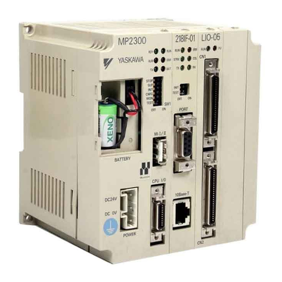
- Page 19 1 Overview of the MP2300 1.1 Features The MP2300 is an all-in-one, compact Machine Controller that combines power supply, CPU, SVB, I/O, and communication functions in one system. The MP2300 consists of a Basic Module that performs motion control and sequence control and Optional Modules that perform I/O and communication functions.
- Page 20 1.2 MP2300 Configuration 1.2 MP2300 Configuration The MP2300 is configured with one Basic Module and up to three Optional Modules. 1.2.1 Basic Module Appearance The following figure shows the external appearance of the Basic Module. LED indicators MP2300 Switches Battery holder...
- Page 21 1 Overview of the MP2300 1.2.2 MP2300 Modules 1.2.2 MP2300 Modules The following table shows the names and descriptions of the Basic Module and Optional Modules. Group Name Description Model Remarks MECHATROLINK-I, JEPMC-MP2300-E Basic Module Basic Module MP2300 MECHATROLINK-II JEPMC-MP2300...
- Page 22 For the details on the system configuration example, refer to 4.1.2 System Configuration on page 4-3. Use the connecting cables and connectors recommended by Yaskawa. Always check the device to be used and select the correct cable for the device.
- Page 23 1.4.1 Devices Connectable to MECHATROLINK-I/II 1.4 Devices Connectable to MECHATROLINK 1.4.1 Devices Connectable to MECHATROLINK-I/II The devices that are compatible with MECHATROLINK-I/II and can be connected to the MP2300 and the SVB-01 Module are listed below. ( 1 ) Compatible SERVOPACKs...
- Page 24 1.4 Devices Connectable to MECHATROLINK (cont’d) Model Number Details MECHATROLINK-I MECHATROLINK-II JEPMC-IO2310 64-point I/O Module JEPMC-IO2310-E 24 VDC, 64 inputs, 64 outputs (sink) JEPMC-IO2330 64-point I/O Module JEPMC-IO2330-E 24 VDC, 64 inputs, 64 outputs (source) JEPMC-PL2900 Counter Module JEPMC-PL2900-E Reversible counter, 2 channels JEPMC-PL2910 Pulse Output Module JEPMC-PL2910-E...
- Page 25 1 Overview of the MP2300 1.4.2 Devices Connectable to MECHATROLINK-III 1.4.2 Devices Connectable to MECHATROLINK-III The devices that are compatible with MECHATROLINK-III and can be connected to the SVC-01 Module are listed below. ( 1 ) Compatible SERVOPACKs Model Number Details SGDV-2...
- Page 26 1.5 Cables, Accessories and Optionals, and Software 1.5 Cables, Accessories and Optionals, and Software 1.5.1 Cables The following table shows the cables that can be connected to the MP2300 Basic Module and Optional Modules. Connector Module Application Model Specifications Name...
- Page 27 1 Overview of the MP2300 1.5.1 Cables (cont’d) Connector Module Application Model Specifications Name JEPMC-W6090- Used between AO-01 Analog external outputs • Loose wires on one end AO-01 and Analog external input device JEPMC-W6060- Used between DO-01 CN1, CN2 External outputs •...
- Page 28 JEPMC-OP300 2 parts for 1 set Option Slot Cover Optional JEPMC-OP2300 Front cover for empty slot 1.5.3 Software (Programming Tool (Options)) The MPE720, programming tool for MP2300, is available. Name Model Remarks MPE720 CPMC-MPE720 (Ver 4.41A or later) CD-ROM MPE720 Ver 6...
-
Page 29: Table Of Contents
2.1.3 Function Specifications - - - - - - - - - - - - - - - - - - - - - - - - - - - - - - - - - - - - - - - - - - - - - 2-4 2.2 MP2300 Basic Module Functions - - - - - - - - - - - - - - - - - - - - - - - - - - - - - - 2-6 2.2.1 External Appearance, LED Indicators, and Switch Settings - - - - - - - - - - - - - - - - - - - - 2-6... -
Page 30: Mp2300 Basic Module Specifications
2 Module Specifications 2.1.1 Hardware Specifications 2.1 MP2300 Basic Module Specifications This section describes the Basic Module Specifications of the MP2300. 2.1.1 Hardware Specifications The following table shows the hardware specifications of the Basic Module. Item Specifications Classification Basic Module... -
Page 31: Environmental Conditions
2.1 MP2300 Basic Module Specifications 2.1.2 Environmental Conditions Item Specifications Ambient Operating 0°C to 55°C Temperature Ambient Storage -25°C to 85°C Temperature Ambient Operating 30% to 95% (with no condensation) Environmental Humidity Conditions Ambient Storage 5% to 95% (with no condensation) -
Page 32: Function Specifications
2 Module Specifications 2.1.3 Function Specifications 2.1.3 Function Specifications ( 1 ) PLC Function Specifications The following table shows the PLC function specifications. Item Specifications Control Method Sequence: High-speed and low-speed scan methods Programming Ladder diagram: Relay circuit Language Text-type language:Numeric operations, logic operations, etc. Two scan levels: High-speed scan and low-speed scan High-speed scan time setting: 1 to 32 ms (Integral multiple of MECHATROLINK... - Page 33 2.1 MP2300 Basic Module Specifications ( 2 ) Motion Control Function Specifications The following table lists the motion control function specifications for the MP2300. Item Specifications Interface MECHATROLINK-I, MECHATROLINK-II Number of Controlled Axes/Module Up to 16 axes (up to 48 axes when two SVB Modules are mounted)
-
Page 34: Mp2300 Basic Module Functions
2.2 MP2300 Basic Module Functions MP2300 Basic Module is an all-in-one, compact module that combines power supply, CPU, built-in SVB, and I/O in one module. The Basic Module has both motion control and sequence control functions. With the 3-slot option slot configuration, Optional Modules can be selected freely and the optimum system can be built for your machine. - Page 35 2.2 MP2300 Basic Module Functions ( 2 ) Indicators The following table shows the indicators that show the operating status of the Basic Module and error information. Indicator Color Status Green Lit during normal operation. Green Lit during execution of user program.
-
Page 36: Module Configuration Definitions
2 Module Specifications 2.2.2 Module Configuration Definitions 2.2.2 Module Configuration Definitions Configuration of the MP2300 including Basic Module and Optional Modules can be obtained and modified in the Module Configuration Window. ( 1 ) Module Configuration Window Components A typical MP2300 Module Configuration Window is shown below. - Page 37 SVB definition file. Additionally, module definition data can be automatically refreshed by executing the self- configuration function when starting the MP2300 or anytime thereafter. For information on how to execute the self-configuration function, refer to 5.4.2 Execution Procedure for Self-config- uration Using the DIP Switch on page 5-30 and 5.4.3 Execution Procedure for Self-configuration Using MPE720 on...
-
Page 38: Cpu I/O (Built-In I/O) Module
2.2.3 CPU I/O (Built-in I/O) Module 2.2.3 CPU I/O (Built-in I/O) Module The CPU I/O Module is a digital I/O module built in the MP2300 Basic Module, and provides eight external input points and four external output points. ( 1 ) CPU/IO Module Details For CPU I/O Module details including specifications, refer to 3.2.4 CPU I/O (Built-in I/O) Connectors on page 3-16. - Page 39 2.2 MP2300 Basic Module Functions The following items are displayed in the Local I/O Window. The discrete inputs, discrete outputs, and interrupt inputs can be set. D : Enable or disable each item by clicking on the cell. : Enabled, : Disabled The register length is fixed at one word, i.e., 16 points are set for each input or output register.
-
Page 40: Built-In Svb Modules
The SVB Modules are of two types: The built-in SVB (hereinafter referred to as Built-in SVB) and the slot-mounting optional SVB (hereinafter referred to as Optional SVB). A built-in SVB Module is incorporated in MP2300 Basic Module as a standard feature. For built-in SVB Module specifications, refer to 2.2.6 Built-in SVB Specifications on page 2-25. - Page 41 2.2 MP2300 Basic Module Functions ( 2 ) System Configuration Example The following diagram shows a system configuration example. MP2300 SVB-01 218IF LIO-01 24-VDC power External I/O supply Control panel External I/O RS-232C MECHATROLINK-II MPE720 Ethernet MECHATROLINK- Servos compatible I/O Modules...
- Page 42 ( 3 ) Synchronization between Modules [ a ] Overview MP2300 Machine Controllers have a function that can synchronize hardware between the CPU and an optional module. This function enables MECHATROLINK communications in synchronization with high-speed scans. As a result, synchronization between a built-in SVB Module and an SVB-01 Module, or among multiple SVB-01 Modules, can be enabled.
- Page 43 2.2 MP2300 Basic Module Functions [ d ] Operation when High-speed Scan Cycle Is Changed MECHATROLINK communication with SVB Modules will continue even if the high-speed scan cycle is changed. However, the speed waveform at execution of interpolation command will be disordered. When changing the high- speed scan cycle, do so either with the CPU stopped or when motion command are not being executed.
-
Page 44: Setting Svb Module
2 Module Specifications 2.2.5 Setting SVB Module 2.2.5 Setting SVB Module A SERVOPACK connected to MECHATROLINK can be controlled by executing the MECHATROLINK transmission definition and SVB definition with the MPE720 Engineering Manager. ( 1 ) MECHATROLINK Transmission Definition [ a ] How to Open the MECHATROLINK Transmission Definition Window In the Module Configuration Window, select the SVB Module in the Controller field and double-click the MECHATROLINK cell in the Details field. - Page 45 2.2 MP2300 Basic Module Functions [ b ] MECHATROLINK Transmission Definition Window Details The MECHATROLINK Transmission Definition Window has four tabs: Transmission Parameters, Link Assignment, I/O Map, and Status. Click the tab to view each. Transmission Parameters Tab The parameters required to use the MECHATROLINK transmission system are displayed.
- Page 46 2 Module Specifications 2.2.5 Setting SVB Module (cont’d) Item Display during Self-configuration Options and Precautions on Settings SigmaWin+ For MECHATROLINK-II communications, displays (Hidden for whether or not to use SigmaWin+ for communication via Select either use or not use. MECHATROLINK MECHATROLINK-II adapter such as JUSP-NP115.
- Page 47 2.2 MP2300 Basic Module Functions ■ Communication Cycle That Can be Set The communication cycle that can be set will differ depending on the SVB Module type (built-in SVB or optional SVB) and the communication type as follows. SVB Module Type...
- Page 48 2 Module Specifications 2.2.5 Setting SVB Module Link Assignment Tab Page The data of the slave devices (MECHATROLINK connected devices such as SERVOPACK, inverter, and distributed I/ O) are displayed on the Link Assignment Tab. The items shown on the Link Assignment Tab are as follows. You can change the settings or delete the data station by station on this tab.
- Page 49 2.2 MP2300 Basic Module Functions I/O Map Tab The status allocated to I/O registers is displayed. The I/O Map Tab is used for monitoring (read-only). Do not change the displayed settings. Status Tab Page The MECHATROLINK transmission status is displayed. The displayed settings cannot be changed.
- Page 50 2 Module Specifications 2.2.5 Setting SVB Module ( 2 ) SVB Definition The SVB Definition file defines the motion parameters (motion fixed parameters, motion setting parameters, and motion monitoring parameters) to control motion axes such as the SERVOPACK, inverter, and stepper. ...
- Page 51 2.2 MP2300 Basic Module Functions Click the Fixed Parameters, Set Up Parameters, or Monitor tab to display the desired page. If the setting in Servo Type is switched from Rotary to Linear, or vice-versa, some of the displayed parameters will change.
-
Page 52: Built-In Svb Specifications
2 Module Specifications 2.2.6 Built-in SVB Specifications 2.2.6 Built-in SVB Specifications [ a ] MECHATROLINK Communication Specifications Item MECHATROLINK-Ι MECHATROLINK-ΙΙ Topology Transmission Path Electric bus Electric bus 50 m 50 m Transmission Distance (Can be extended up to 100m by (Can be extended up to 100m by connecting repeaters connecting repeaters... -
Page 53: Svr Virtual Motion Module
In the MP2300 Basic Module, slot 4 in the default Module Configuration Window is for SVR. If the SVR is not used, MP2300 processing time can be reduced by setting the Module Type for SVR to UNDEFINED in the Module Configuration Window. - Page 54 The software limit function and machine lock function cannot be used with the SVR. The position error will always be ( 3 ) System Configuration Example The following figure shows an example system configuration using SVR. MP2300 C P U Virtual motion...
- Page 55 2.2 MP2300 Basic Module Functions ( 4 ) SVR Operation [ a ] SVR Execution Timing The SVR is processed at the beginning of the high-speed scan. SVR processing is performed in the next scan after specifying and the processing results are reflected in the monitoring parameters.
-
Page 56: Mounting And Connections
3.1... -
Page 57: Mounting The Mp2300
3 Mounting and Connections 3.1.1 Basic Module Dimensional Drawings 3.1 Mounting the MP2300 3.1.1 Basic Module Dimensional Drawings Refer to the following dimensions for installation. Panel Cutout Dimensions 111±0.2 Four-M4 tap Rear M4 mounting screws (4) Top view Front (18) (4.5) -
Page 58: Mounting The Mp2300
Two types of DIN rails are available: with 7-mm or 10-mm gap from the mounting base as shown in the following dia- gram. If mounting a MP2300 using DIN rail with 10 mm gap, install a spacer on the rear of the MP2300 near the bot- tom to protect the MP2300 from vibration and shock. - Page 59 3.1.2 Mounting the MP2300 [ b ] Procedure for Mounting to DIN Rail Use the following procedure to attach the DIN rail mounting parts to the MP2300 and then mount the MP2300 to the DIN rail. Insert the DIN rails in the two slots on the rear of the MP2300 as shown in the following figure.
- Page 60 3.1 Mounting the MP2300 Hook the MP2300 to the top of the DIN rail (a), and then push the MP2300 towards the mounting base to secure it in place (b). Push the DIN rail mounting clips to lock them in place.
-
Page 61: Replacing And Adding Optional Modules
Remove the MP2300. Turn OFF the power supply and remove all the cables connected to the MP2300. Next, remove the MP2300 from the panel or rack, and place them where there is sufficient space, such as on a work table. - Page 62 3.1 Mounting the MP2300 Remove the Optional Module from the Mounting Base. Pull out on the top of the option panel and remove it. A notch can be seen in the Communication Module from the gap in the panel. Insert the round projection on the battery cover (see the following figure) into the gap in the panel so that it is inserted in the notch in the Module.
- Page 63 3 Mounting and Connections 3.1.3 Replacing and Adding Optional Modules ( 3 ) Mounting Optional Modules Insert Optional Modules. Hold onto the top and bottom of the Module, align the Module with the left side of the guide rail inside the option slot, and insert the Module straight in.
-
Page 64: Basic Module Connections Specifications
3.2 Basic Module Connections Specifications 3.2 Basic Module Connections Specifications 3.2.1 Connectors The following illustration shows the connectors for the Basic Module. MP2300 YASKAWA STOP CNFG MECHATROLINK TEST connector OFF ON M-I/II BATTERY Power supply connector CPU I/O DC24V I/O connector... -
Page 65: Power Supply Connector
3 Mounting and Connections 3.2.2 Power Supply Connector 3.2.2 Power Supply Connector ( 1 ) Specifications, Pin Arrangement, and Connection Procedure Supply a 24-VDC to the MP2300. Connect the power supply connector as shown in the diagram below. Connector Model Connector No. of... - Page 66 3.2 Basic Module Connections Specifications ( 2 ) Assembling the 24-VDC Power Supply Cable A detachable connector is provided for the power supply terminals. Use AWG24 to AWG20 (0.2 mm to 0.51 mm twisted-pair cable to assemble the 24-VDC power supply cable with the following procedure. Strip approx.
-
Page 67: Mechatrolink Connectors
3 Mounting and Connections 3.2.3 MECHATROLINK Connectors 3.2.3 MECHATROLINK Connectors MECHATROLINK connector is used to connect the MP2300 and the SERVOPACKs and distributed I/O via MECHATROLINK cables. ( 1 ) Specifications and Pin Arrangement Connector Model Connector No. of Name... - Page 68 3.2 Basic Module Connections Specifications ( 3 ) Cable Connections between the MP2300 or I/O Units or the MP2300 and SERVOPACKs (Except for SGD-N and SGDB-AN SERVOPACKs) Use the MECHATROLINK cable JEPMC-W6002- or JEPMC-W6003- for connection between the MP2300 and I/O units or SERVOPACKs (Except for SGD-N and SGDB-AN SERVOPACKs) The connection diagram using MECHATROLINK cable JEPMC-W6002-...
- Page 69 The shield wire can be connected as instructed in the SERVOPACK’s manual. However, the connections shown in the above diagram is recommended when using the MP2300 in combination with a SVB-01 Module. Prepare the cables according to MECHATROLINK-Ι specifications. Connections that do not meet the specifi- cations will prevent normal communication due to the influence of reflected waves or other factors.
- Page 70 3.2 Basic Module Connections Specifications ( 6 ) Connection Example between MP2300, SERVOPACK, and IO2310 MP2300 YASKAWA STOP YASKAWA JEPMC-IO2310 CNFG TEST OFF ON OUT1 OUT2 M-I/II BATTERY CPU I/O DC24V DC 0V YASKAWA SERVOPACK 200V YASKAWA SERVOPACK 200V YASKAWA SERVOPACK...
- Page 71 3 Mounting and Connections 3.2.4 CPU I/O (Built-in I/O) Connectors 3.2.4 CPU I/O (Built-in I/O) Connectors CPU I/O connector is used to connect the MP2300 and external I/O signals. ( 1 ) Specifications External input: 8 points, External output: 4 points...
- Page 72 3.2 Basic Module Connections Specifications ( 5 ) Input Circuits The following table shows the CPU I/O Connector input circuit specifications. Item Specifications DI-00 General-purpose input (shared with interrupts) Inputs 8 points DI-01 to DI-07 General-purpose input Input Format Sink mode/source mode input Isolation Method Photocoupler ±...
- Page 73 3 Mounting and Connections 3.2.4 CPU I/O (Built-in I/O) Connectors ( 6 ) Output Circuit The following table shows the CPU I/O Connector output circuit specifications. Item Specifications Outputs 4 points Output Format Transistor, open-collector, sink mode output Isolation Method Photocoupler ±...
- Page 74 3.2 Basic Module Connections Specifications ( 7 ) CPU I/O Connector Connections The following diagram shows the connections for the CPU I/O connector. DI_COM DI_COM 24 VDC Digital input DI_00 DI_01 DI_02 External input DI_03 signals DI_04 DI_05 DI_06 DI_07 DO_24V 24 VDC Fuse...
-
Page 75: System Startup And Sample Programs
Your Computer from the MP2300 - - - - - - - - - - - - - - - - - - - - - - - - - - - - - - - - - - -... -
Page 76: Model System Startup Procedure
Settings for Servo Control on page 4-17 and 4.2.3 Saving Parameters on page 4-28 Data from the MP2300 to Flash Memory, and Transferring Data to Your Computer from the MP2300 on page 4-21. Checking Operation Execute the program and check the test operation. -
Page 77: System Configuration
( 1 ) Controller-related Equipment Name Model Quantity MP2300 JEPMC-MP2300 218IF-01 JAPMC-CM2300 MECHATOROLINK Cables (1 m) JEPMC-W6002-01 Terminator JEPMC-W6022 For mounting the 218IF-01 Module to the MP2300, refer to 3.1.3 Replacing and Adding Optional Modules on page 3-6. - Page 78 PP Cable (for RS-232C connection) JEPMC-W5311-03 PP Cable (for Ethernet connection) Commercially-available cross cable Computer Commercially-available product Above equipments can connect to the MP2300 with eigher RS-232C or Ethernet. ( 3 ) Servodrive-related Equipment Name Model Quantity Σ-III SERVOPACKs SGDS-01A12A Σ-III Servomotors...
-
Page 79: Initializing Servopacks
4.1 Model System Startup Procedure 4.1.3 Initializing SERVOPACKs This section describes the procedure for initializing Σ -III SERVOPACKs using the Digital Operator. Always initialize SERVOPACKs that have been transferred from other systems. SERVOPACKs that are being used for the first time do not need to be initialized. -
Page 80: Setting And Saving Communication Process (Communication Manager)
4.1.4 Setting and Saving Communication Process (Communication Manager) Use the following procedure to set the communication process between the personal computer (MPE720) and the MP2300 using the Communication Manager. These settings are not required if the communication settings have already been made. - Page 81 4.1 Model System Startup Procedure For RS-232C connections, select Serial under Port Kind and then click Detail Button in the Logical Port Setting Dialog Box. The Serial Port Setting Dialog Box appears. Match the settings under Physical Port to the computer’s serial communication port. Leave the other items on the default settings.
- Page 82 4 System Startup and Sample Programs 4.1.4 Setting and Saving Communication Process (Communication Manager) ■ Settings for Ethernet Connection Prior to make settings for Ethernet connection, the IP adderss of the personal computer must be set. Use the following procedure to set the IP address and make settings for Ethernet connection. ...
- Page 83 4.1 Model System Startup Procedure For the computer running Windows 2000 OS, double-click the Local area connection Icon. For the computer running Windows XP OS, select Local area connection and click Change settings of this connection in the Network Task field. <...
- Page 84 4 System Startup and Sample Programs 4.1.4 Setting and Saving Communication Process (Communication Manager) Double-click Logical Port No. 2 in the Communication Process Window to display the Logical Port Setting Dialog Box. Select CP-218 under Port Kind in the Logical Port Setting Dialog Box and click the Detail Button. The CP-218 Port Setting Dialog Box appears.
- Page 85 4.1 Model System Startup Procedure ■ Saving the Communication Port Settings and Restarting Communication Process Window Click File - Save. A save confirmation window will be displayed. Click the Yes Button to save the communication port settings. These settings will be used as the communication port information whenever the communication process is started.
-
Page 86: Mp2300 Self-Configuration
Also, flash memory data will be read and RAM data will be overwritten when the INIT switch is OFF and the power is turned ON. In either case, the RAM data will be cleared by turning the power ON. Therefore, always save data to the MP2300 flash memory before turning OFF the power when writing or editing programs. -
Page 87: Starting The Sample Program - Mpe720 Ver 6
This section describes how to copy the sample program file from MPE720 Ver 6. installation disk, how to start MPE720 Ver 6. to transfer the sample program to the MP2300, and how to set and save parameters, according to the following flowchart. - Page 88 Copy the sample program file 2300SMPL_E.YMW, and paste it in a folder in the hard disk. ( 2 ) Starting MPE720 Ver 6. To Transfer the Sample Program to the MP2300 Double-click the 2300SMPL_E.YMW file copied to the hard disk.
- Page 89 Select the Program Check Box. Then, select the Ladder program, Main program and Group definition Check Boxes under Motion Program. Click the Start Button. A message box will appear and ask whether or not to stop the MP2300 to allow transfer of the files. 4-15...
- Page 90 Click the CPU STOP Button. The MP2300 will stop running and MPE720 will start transferring the selected sample program files. When the transfer is complete, a message box will appear to tell you that the sample program files have been successfully written to the MP2300.
-
Page 91: Setting Motion Fixed Parameters And Adjusting The Settings For Servo Control
4.2.2 Setting Motion Fixed Parameters and Adjusting the Settings for Servo Control ( 1 ) Setting and Saving Motion Fixed Parameters This section describes how to set and save MP2300 motion fixed parameters for Axes 1 and 2 according to the sample program. - Page 92 4 System Startup and Sample Programs 4.2.2 Setting Motion Fixed Parameters and Adjusting the Settings for Servo Control Set the fixed parameters for axis 1. Select Axis 1 from the axis selection box at the top-left of the window and select mm under No. 4 Reference unit selection on the Fixed Parameters Tab Page.
- Page 93 Select Edit - Copy Current Value. A confirmation dialog box will appear. The data in the Input Data Column is the SERVOPACK data saved to the MP2300 and the data in the Current Value Column is the data set to the SERVOPACK.
- Page 94 4.2.2 Setting Motion Fixed Parameters and Adjusting the Settings for Servo Control Select File - Save to save the SERVOPACK settings for axis 1 to the MP2300. Follow steps 2 to 5 to write and save the SERVOPACK current position for axis 2 as settings data as well.
-
Page 95: Saving Data From The Mp2300 To Flash Memory, And Transferring Data To Your Computer From The Mp2300
Check to see that the target controller displayed in the dialog box is correct, and then click the Start Button. A message box will appear and ask whether or not to stop the MP2300 while saving data to the flash memory. Click the NO Button to stop the MP2300 and start saving the data to the flash memory. - Page 96 4 System Startup and Sample Programs 4.2.3 Saving Data from the MP2300 to Flash Memory, and Transferring Data to Your Computer from the MP2300 ( 2 ) Transferring Data from the MP2300 to Your Computer Use the following procedure to transfer data from the MP2300 RAM to a computer.
-
Page 97: Starting Sample Program - Mpe720 Ver 5
4.3 Starting Sample Program - MPE720 Ver 5. The following flowchart describes the method used for reading the sample program from the installation disk of MPE720 Ver 5., and for setting and saving parameters after starting the MP2300 using MPE720 Ver 5. Starting the MPE720 4.3.1 ( 1 ) Starting the MPE720 Ver 5. -
Page 98: Starting Mpe720 Ver 5. And Creating Folders
This section describes the preparation for connecting the MPE720 (motion programming software, optional) to the MP2300 and the method for installing the sample program for the MP2300. The explanation is given assuming that the MPE720 has been installed on your personal computer. - Page 99 4.3 Starting Sample Program - MPE720 Ver 5. ( 2 ) Creating Group Folders (Option) In the File Manager Window, create a group folder for storing order folders. Refer to Group Folders, Order Folders, Controller folders at the bottom of this page for more information about these folders.
- Page 100 4 System Startup and Sample Programs 4.3.1 Starting MPE720 Ver 5. and Creating Folders ( 3 ) Creating Order Folders (Required) In the File Manager Window, create an Order Folder for storing Controller Folders. Right-click (root) or the Group Folder in which the Order Folder is to be created and select New - Order Folder from the pop-up menu.
- Page 101 Folder - Controller Folder from the pop-up menu. The Controller Configuration Dialog Box will appear. Enter a Controller Folder name of up to 8 characters under Controller Name, select MP2300 under Controller Type, and click the OK Button. A new Controller Folder will be created. Click the Order Folder or to display the entered Controller Folder name.
-
Page 102: Reading Sample Programs And Setting And Saving Parameters
4.3.2 Reading Sample Programs and Setting and Saving Parameters This section use sample programs to explain how to log on after being connected to the MP2300, transfer programs, set motion fixed parameters, and log off. The following flowchart outlines the order of the explanations. - Page 103 4.3 Starting Sample Program - MPE720 Ver 5. Select the Network Tab Page and check that OnLine is set to Yes. Under Logical Port No. (Device Type), select the logical port number to be used, from the logical ports set using the communication process.
- Page 104 4 System Startup and Sample Programs 4.3.2 Reading Sample Programs and Setting and Saving Parameters < For RS-232C Connection > Leave the values other than the Logical Port No on their default settings, and click OK Button. <For Ethernet Connection > Enter the IP address of the Communication Module at the MP2000 Series Machine Controller and click OK Button.
- Page 105 4.3 Starting Sample Program - MPE720 Ver 5. ■ Logging On Online When using MPE720 Ver 5., logging on is performed for each Controller Folder. Controller Folders that have not been logged onto cannot use the MPE720 functions. Right-click on the Conroller Folder that was selected in step 1 and select Log On from the pop-up menu that is displayed.
- Page 106 4 System Startup and Sample Programs 4.3.2 Reading Sample Programs and Setting and Saving Parameters ( 2 ) Loading the Sample Programs The sample programs on the MPE720 system CD-ROM will be decompressed on the personal computer and loaded to the Controller Folder.
- Page 107 4.3 Starting Sample Program - MPE720 Ver 5. Deselect Compression transmission. Check the Source. If the Source is different from the decompression destination folder, click the Change Button and continue to step 5. If the Source is correct, move to step 6. The Change Transfer Drive Dialog Box will appear.
- Page 108 The All Media to MPE720 Window will appear. Select File - Exit to end reading files to the MPE720. ( 3 ) Transfer Individual Programs Transfer the programs that have been read to the MPE720 individually to the MP2300. Right-click on the Controller Folder that has been logged onto online and select Transfer - Selected Files - From MPE720 to Controller from the pop-up menu that is displayed.
- Page 109 4.3 Starting Sample Program - MPE720 Ver 5. Select the programs to be transferred. For programs with a Details Button next to them, click the Details Button and select the individual function programs for the program listed in the Set Details Dialog Box that is displayed.
- Page 110 4 System Startup and Sample Programs 4.3.2 Reading Sample Programs and Setting and Saving Parameters Select File - Execute. Click the Yes Button in the confirmation dialog box to start the file transfer. When the transfer has been completed, a confirmation dialog box will appear again. Click the OK Button. Select File - Exit in the Individual Load Window to exit the transfer.
- Page 111 4.3 Starting Sample Program - MPE720 Ver 5. Select 00 in the Controller Area and double-click the 3 in the Module Details MP2300 SLOT≠00 Area in the Module Configuration Window. The SVB Definition Window with Fixed Parameters Tab Page will appear.
- Page 112 Select Edit - Copy Current Value. A confirmation dialog box will appear. The data in the Input Data Column is the SERVOPACK data saved to the MP2300 and the data in the Current Value Column is the data set to the SERVOPACK.
- Page 113 4.3 Starting Sample Program - MPE720 Ver 5. Select File - Save to save the SERVOPACK settings for axis 1 to the MP2300. Follow steps 2 to 5 to write and save the SERVOPACK current position for axis 2 as settings data as well.
- Page 114 4.3.2 Reading Sample Programs and Setting and Saving Parameters ( 6 ) Saving to Flash Memory Save sample programs that have been transferred individually to the MP2300 to the MP2300 flash memory using the procedure below. Right-click the Controller Folder in which the sample programs have been saved and select Transfer - Other - Save to Flash from the pop-up menu that is displayed.
- Page 115 Execute All Program File Dump to back up to a personal computer the module configuration definitions automatically detected by the MP2300 during self-configuration and edited programs. The MP2300 program data and the program data in the personal computer hard disk are synchronized when all programs are dumped.
-
Page 116: Other Operations
4 System Startup and Sample Programs 4.3.3 Other Operations 4.3.3 Other Operations This section describes the CPU RUN setting and log-off operation required when MPE720 Ver 5. is used. ( 1 ) CPU RUN Settings If the CPU STOP status is not cleared after executing processes such as saving to flash memory, use the following procedure to return to RUN status. - Page 117 4.3 Starting Sample Program - MPE720 Ver 5. ( 2 ) Logging Off Log off once the work using MPE720 (Embedded) has been completed. Right-click on the Controller Folder where sample programs are saved and select Log Off from the pop-up menu that is displayed.
-
Page 118: Checking Sample Program Operation
4 System Startup and Sample Programs 4.4.1 How to Open the Tuning Panel Window 4.4 Checking Sample Program Operation This section describes how to check four operations in the model system applying sample programs started in 4.3 or 4.4 by using the Tuning Panel Window for sample programs. 4.4.1 How to Open the Tuning Panel Window ( 1 ) From Engineering Manager Window Use the following procedure to open the Tuning Panel Window from the Engineering Manager Window. - Page 119 4.4 Checking Sample Program Operation ( 2 ) From the File Manager Window (For MPE720 Ver 5. Only) When using MPE720 Ver 5., the Tuning Panel Window can also be opened from the File Manager Window by using the following procedure. Log on online, open the Programs folder, and then open the High Scan Programs folder in the PLC folder where the sample programs are saved in the File Manager Window.
-
Page 120: Operation Check 1: Manual Operation
Refer to 4.4.2 ( 4 ) Sample Program Details on page 4-49 for details of each program (drawing). A simple device is used in this example to describe the MP2300 system startup. This device has no power OFF circuit for the SERVOPACK in the event of emergency stops or overtravel. Include a proper emergency stop circuit in actual devices. - Page 121 4.4 Checking Sample Program Operation ( 2 ) H02 Drawing Tuning Panel Display the H02 Drawing Tuning Panel as shown in 4.4.1 How to Open the Tuning Panel Window on page 4-44. Model system operation can be controlled by writing the current values for common operation and Manual Operation and Setting from the Tuning Panel.
- Page 122 4 System Startup and Sample Programs 4.4.2 Operation Check 1: Manual Operation ( 3 ) Procedure Use the following procedure to confirm operation. Servo ON Start JOG or STEP operation. Confirm operation. The following table gives an outline of the operation when the Tuning Panel window is used. Current Value Data Name Operation Outline...
- Page 123 4.4 Checking Sample Program Operation ( 4 ) Sample Program Details [ a ] H Drawing The H parent drawing controls the overall sample program. P00101 H Main Program: High-speed Main Program High-speed main program Servo ON and Alarm reset Servo ON, alarm reset 0000 0000...
- Page 124 4 System Startup and Sample Programs 4.4.2 Operation Check 1: Manual Operation ########## Speed Unit and Acceleration/Deceleration Unit Selection ########## Bits 0 to 3: Speed Unit Selection (0: Reference unit/s; 1: Reference unit/min.; 2: Percentage) Bits 4 to 7: Acceleration/Deceleration Unit Selection (0: Reference unit/s; 1: ms) Axis 1 Function Settings 1 (unit) Axis 1 Function Settings 1 work 0006...
- Page 125 4.4 Checking Sample Program Operation [ d ] H02.01 Drawing The H02.01 grandchild drawing controls JOG and STEP operation for axis 1. ##########Axis 1 Manual operation (JOG and STEP)########## ##########JOG########## Axis 1 JOG Axis 1 jog command Axis 1 forward jog Axis 1 reverse jog Axis 1 SV_ON DB000000...
- Page 126 4 System Startup and Sample Programs 4.4.2 Operation Check 1: Manual Operation [ e ] H02.02 Drawing The H02.02 grandchild drawing controls JOG and STEP operation for axis 2. ##########Axis 2 Manual operation (JOG and STEP)########## ##########JOG########## Axis 2 JOG Axis 2 forward jog Axis 2 reverse jog Axis 2 SV_ON...
-
Page 127: Operation Check 2: Position Control
Refer to 4.4.3 ( 5 ) Sample Program Details on page 4-56 for details of each program. A simple device is used in this example to describe the MP2300 system startup. This device has no power OFF circuit for the SERVOPACK in the event of emergency stops or overtravel. Include a proper emergency stop circuit in actual devices. - Page 128 4 System Startup and Sample Programs 4.4.3 Operation Check 2: Position Control ( 3 ) H04 Drawing Tuning Panel Display the H04 Drawing Tuning Panel as shown in 4.4.1 How to Open the Tuning Panel Window on page 4-44. Model system operation can be controlled by writing the current values for Common operation and Positioning operation and settings from the Tuning Panel.
- Page 129 4.4 Checking Sample Program Operation ( 4 ) Procedure Use the following procedure to operate the Tuning Panel and check operation. Servo ON Change the Servo ON PB current value from OFF to ON. The Servomotor will turn ON and the Servo will be clamped. Motion program No.
- Page 130 4 System Startup and Sample Programs 4.4.3 Operation Check 2: Position Control ( 5 ) Sample Program Details [ a ] H04 Drawing The H04 child drawing contains the ladder program for managing and controlling MPM motion programs. Positioning Main Processing ########## 位置決め動作メイン処理 ########## ########## モーションプログラム起動シーケンス...
- Page 131 4.4 Checking Sample Program Operation [ b ] Motion Program MPM001 The MPM001 motion program uses the Servomotor phase-C pulse to perform home return. 00001 "MPM001"; 00002 OW803C=3; "X axis home return method selection (3: Phase C)" 00003 OW80BC=3; "Y axis home return type selection (3: Phase C)" 00004 VEL [X]1000 [Y]1000;...
-
Page 132: Operation Check 3: Phase Control - Electronic Shaft
Refer to 4.4.4 ( 5 ) Sample Program Details on page 4-60 for details of H06.01 Drawing. A simple device is used in this example to describe the MP2300 system startup. This device has no power OFF circuit for the SERVOPACK in the event of emergency stops or overtravel. Include a proper emergency stop circuit in actual devices. - Page 133 4.4 Checking Sample Program Operation ( 3 ) H06 Drawing Tuning Panel Display the H06 Drawing Tuning Panel as shown in 4.4.1 How to Open the Tuning Panel Window on page 4-44. Model system operation can be controlled by writing the current values for Common operation and Phase control (electric shaft) from the Tuning Panel.
- Page 134 4 System Startup and Sample Programs 4.4.4 Operation Check 3: Phase Control - Electronic Shaft ( 5 ) Sample Program Details [ a ] H06.01 Drawing The H6.01 grandchild drawing shows the ladder program for controlling phase control (electronic shaft) operation. ########## Phase Control 1 (Electronic Shaft) ########## ########## Electronic Shaft Operation Command ########## Electronic shaft operation command...
- Page 135 4.4 Checking Sample Program Operation Motion command 0 (NOP) setting Electronic shaft stop Axis 1 motion command DB000002 0005 STORE 0017 Source 00000 NL-1 Dest OW8008 Electronic shaft stop DB000002 Axis 2 motion command 0006 STORE 0019 Source 00000 NL-1 Dest OW8088 S-curve Acceleration/deceleration Setting S-curve accelerator/decelerator input...
-
Page 136: Operation Check 4: Phase Control - Electronic Cam
Refer to 4.4.5 ( 5 ) Sample Program Details on page 4-64 for details of H06.01 Drawing. A simple device is used in this example to describe the MP2300 system startup. Caution is required because actual applications will be different. - Page 137 4.4 Checking Sample Program Operation ( 3 ) H06 Drawing Tuning Panel Display the H06 Drawing Tuning Panel as shown in 4.4.1 How to Open the Tuning Panel Window on page 4-44. Model system operation can be controlled by writing the current values for Common operation and Phase control (electric shaft) from the Tuning Panel.
- Page 138 4 System Startup and Sample Programs 4.4.5 Operation Check 4: Phase Control - Electronic Cam ( 5 ) Sample Program Details [ a ] H06.02 Drawing The H06.02 grandchild drawing controls phase control (electronic cam) operation. P00121 H06.02 Main Program: Phase Control 2 (Electronic Cam) ########## Phase Control 2 (Electronic Cam) ########## ########## Description ##########...
- Page 139 4.4 Checking Sample Program Operation P00122 H06.02 Main Program: Phase Control 2 (Electronic Cam) Operation command DB000000 Linear accelerator/decelerator input 0010 STORE 0028 Source 0.000000E+000 NL-1 Dest DF00012 Linear accelerator/decelerator input 0011 0030 Input DF00012 NL-1 Parameter DA00020 Output DF00040 Operation command DB000000 Axis 1 speed command setting...
- Page 140 4 System Startup and Sample Programs 4.4.5 Operation Check 4: Phase Control - Electronic Cam Main Program Phase Control 2 (Electronic Shaft) P00123 H06.02 メインプログラム 位置制御2(電子カム)処理 Detection in forward direction 正方向検出 Electronic cam phase 電子カム位相 DB000008 0020 SUBX 0043 SourceA DL00066 NL-1 SourceB ML30202 Dest DL00066...
- Page 141 4.4 Checking Sample Program Operation [ b ] L Drawing The L parent drawing manages the low-speed scan that controls the overall sample program. Main Program: Low-speed Main Program P00125 L メインプログラム 低速メインプログラム Low-speed Main Program ########## 低速メインプログラム ########## ##########Electronic Cam Table Data Generation########## ########## 電子カムテーブルデータ生成...
-
Page 142: System Startup Using Self-Configuration
The servo adjustment can be performed either in this step or after the self-configuration. Set the Switches on MP2300/Optional Module Set the switches of SW1 on MP2300 as shown below. STOP INIT CNFG TEST Make switch settings for communication and station address on each Optional Module mounted on the MP2300 as required. 4-68... - Page 143 4.5 System Startup Using Self-Configuration Execute Self-configuration. Check that all MECHATROLINK slaves have started up normally, then turn ON the power to the MP2300 to start self-configuration. The LED indicators on the MP2300 Basic Module change as shown below. : Blinking...
- Page 144 4.5.1 Starting the System for First Time b) Select Edit - Copy Current Value. The data in the Input Data column in the SERVOPACK data saved to the MP2300 and the data in the Current Value column is the data set to the SERVOPACK.
-
Page 145: System Startup When Adding Electronic Devices
Back Up Applications. Before adding the electronic devices, create a backup of the application. For information on how to create a backup, refer to 4.2.3 ( 2 ) Transferring Data from the MP2300 to Your Com- puter on page 4-22 (MPE720 Ver 6. - Page 146 4.5.2 System Startup when Adding Electronic Devices Make Parameter Settings to Match Machinery. Save SERVOPACK Parameters. Save MP2300 Data to Flash Memory. Save Ladder Programs and Restart MP2300. This completes the system startup procedure when electronic devices have been added.
-
Page 147: System Startup When Replacing Electronic Devices
Once normal startup has been confirmed, turn OFF the power supply. Replace the Electronic Device. Remove the electronic device to be replaced, connect the new device to the MP2300, and turn ON the power to all MECHATROLINK slaves. - Page 148 4.5.3 System Startup when Replacing Electronic Devices Turn ON the MP2300 and SERVOPACKs Turn ON (OFF to ON) the power to the MP2300 and SERVOPACKs and then enable the parameters written to the SERVOPACKs. This completes the system startup procedure when electric devices have been replaced.
-
Page 149: Outline Of Motion Control Systems
5.4.4 Definition Data Refreshed by Self-configuration - - - - - - - - - - - - - - - - - - - - - - - - - - - 5-36 5.5 Precautions When Using the MP2300 - - - - - - - - - - - - - - - - - - - - - - - - - 5-38 5.5.1 Precautions when Setting or Changing User Definition Files - - - - - - - - - - - - - - - - - - 5-38... -
Page 150: Startup Sequence And Basic Operation
5 Outline of Motion Control Systems 5.1.1 DIP Switch Settings 5.1 Startup Sequence and Basic Operation This section describes the MP2300 startup sequence and basic operation together with the DIP switch settings, self- diagnosis at startup, and LED indicator patterns. 5.1.1 DIP Switch Settings Set the DIP switch on the Basic Module to control operations of the startup sequence. -
Page 151: Startup Sequence
5.1 Startup Sequence and Basic Operation 5.1.2 Startup Sequence The startup sequence for the MP2300 from the moment when the power has been turned ON is shown in the following flowchart. Power ON Startup self-diagnostics (1) Judges the Memory clear... -
Page 152: Startup Sequence Operation Details
First scan processing is executed once DWG.A has been completed and the high-speed or low-speed scan time has elapsed. System I/O are executed from the first scan. ( 4 ) Operation Stop MP2300 stops motion control operation when the STOP switch is ON (STOP) and in the following circumstances. Cause Restart method Power supply turned OFF Turn ON the power again. -
Page 153: Led Indicator Details
5.1.4 LED Indicator Details The MP2300 performs a variety of diagnostics at startup. If an error is found, the ERR LED indicator blinks red. The number of times the indicators blink differs depending on the error details, so error details can be determined from counting the number of blinks.The following table shows details of MP2300 LED indicator. -
Page 154: User Programs
5.2.1 Ladder Drawings (DWG) 5.2 User Programs User programs for executing machine control using the MP2300 include ladder programs and motion programs. This section describes the basic operation and other information about user programs. For programming details, refer to the following manuals. -
Page 155: Execution Control Of Drawings
5.2 User Programs The following table provides details of the number of drawings for each drawing. Number of Drawings Drawing DWG.A DWG.I DWG.H DWG.L Parent Drawings 1 (A) 1 (I) 1 (H) 1 (L) Operation Error 1 (A00) 1 (I00) 1 (H00) 1 (L00) Processing Drawings... - Page 156 5 Outline of Motion Control Systems 5.2.2 Execution Control of Drawings ( 3 ) Hierarchical Structure of Drawings Each processing program is made up of parent drawings, child drawings, and grandchild drawings. Parent drawings cannot call child drawings from a different type of drawing and child drawings cannot call grandchild drawings from a different type of drawing.
- Page 157 5.2 User Programs ( 4 ) Drawing Execution Processing Method The execution processing of hierarchical drawings are performed by calling lower-level drawings from higher-level drawings. The following figure shows the execution processing for drawings, using DWG.A as an example. System programs are started according to execution conditions.
-
Page 158: Motion Programs
( = 1 to 256) Specify a different MPM and MPS program number () between 1 and 256 for each program. The MP2300 can execute up to 16 motion programs simultaneously. An alarm (no system work error ) will occur if 17 or more programs are executed simultaneously. - Page 159 A group of axes with related operations can be treated as one group by motion programs and programs can be executed for each group. This allows one MP2300 to independently control multiple machines using group operation. Group operation can be single group operation or multiple group operation.
-
Page 160: Motion Programs And Msee And S Registers
5 Outline of Motion Control Systems 5.2.4 Motion Programs and MSEE and S Registers 5.2.4 Motion Programs and MSEE and S Registers Motion program status, control signal, interpolation override, and system work number data is saved in four MSEE registers (4 words) with a DA (: hexadecimal number) leading address. This data is called every time the MSEE command is executed in an H drawing. - Page 161 5.2 User Programs ( 2 ) Motion Program Control Signals (DA+1) Program control signals (e.g., program operation start requests and program stop requests) need to be entered to exe- cute the motion program called from DWG.H using the MSEE command. The second word of the MSEE work regis- ters (DA+1) is the motion program control signal.
- Page 162 5 Outline of Motion Control Systems 5.2.4 Motion Programs and MSEE and S Registers Stop Request Control signal: Operation start request Control signal: Stop request Control signal: Alarm clear Status: Operating Status: Stopped One scan Status: Alarm One scan Distribution (MVS) Distribution (MOV) ...
- Page 163 5.2 User Programs ( 5 ) Monitoring Motion Program Execution Information Using S Registers The S registers (SW03200 to SW04191) can be used to monitor motion program execution information. ■ Register Areas for Motion Program Execution Information Executing program number Motion program execution information SW03200 SW03200...
- Page 164 5 Outline of Motion Control Systems 5.2.4 Motion Programs and MSEE and S Registers ■ Details of Program Information Used by Work n Program information used by work n Program status Program control signal Executing program number Executing block number Parallel 0 information Error code Parallel 1 information...
- Page 165 5.2 User Programs [ a ] When Bit D of Motion Program Control Signal (System Work Number Setting) is ON The execution information is reported to the “Program information used by work n” registers (SW03264 to SW04133). For example, when the system work number is 1, the motion program execution information can be monitored using SW03246 to SW03321 “Program information used by work 1.”...
-
Page 166: Example Of Ladder Programs For Motion Program Control
The servo ON signal (IB00100) sets the Servo ON motion settings parameter (OB80000) and turns ON the Servo. The signals connected to the MP2300 external input signals are stored as the motion program control signals. IW0000 (external input signal) → DW00001 (Second word of MSEE work registers) •... - Page 167 5.2 User Programs If the above ladder program is used to enter external input signals connected to the MP2300 (IB00000 to IB00005) to DW00001 (second word of MSEE work registers) as the motion program control signals, motion program operations such as run, pause, and stop can be performed using the system’s motion management function.
-
Page 168: Functions
5 Outline of Motion Control Systems 5.2.6 Functions 5.2.6 Functions Functions are executed by calling them from parent, child, or grandchild drawings using the FSTART command. Functions can be called from any drawing, and the same function can be called at the same time from different types of drawings and from different levels of drawings. -
Page 169: Registers
MPE720 Drawings Properties Window. Refer to the Machine Controller MP900/MP2000 Series User’s Manual MPE720 Software for Programming Device (SIEPC88070005) for details. S and M register data has a battery backup to ensure the data is held even if the MP2300 power is turned OFF and ON. - Page 170 5 Outline of Motion Control Systems 5.3.1 Types of Registers ( 2 ) Function Registers The following table shows the registers that can be used with each function. Type Name Specification Method Range Details Characteristics Input to functions Bit input: XB000000 to XB00000F Function input XW00000 to XB, XW, XL, XFnnnnn...
- Page 171 5.3 Registers ( 3 ) Register Ranges in Programs The following figure shows DWG programs, function programs, and register call ranges. Common DWG registers DWG H (drawing) System registers Program (SB, SW, SL, SFnnnnn) 1000 steps max. Data registers (MB, MW, ML, MFnnnnn) DWG registers Constant data, 16384 words max.
-
Page 172: Data Types And Register Specifications
5 Outline of Motion Control Systems 5.3.2 Data Types and Register Specifications 5.3.2 Data Types and Register Specifications There are five kinds of data: Bit, integer, double-length integer, real number, and address data. Each is used differently depending on the application. Address data, however, is used only inside functions when specifying pointers. The following table shows the types of data. - Page 173 5.3 Registers Pointer Specification Register area Address in memory [ MA00100 ] Indicates registers with consecutive multiple addresses with MA00100 as the leading address 5-25...
-
Page 174: Using I And J Subscripts
5 Outline of Motion Control Systems 5.3.3 Using i and j Subscripts 5.3.3 Using i and j Subscripts There are two special register modifiers, i and j, that can be used with relay and register numbers. The functions of i and j are exactly the same. - Page 175 5.3 Registers 5.3.4 Register Specification Methods Registers can be specified directly by register number or by symbol (register name) specification. A combination of both of these register specification methods can be used in ladder programs. When using the symbol specification method, the relationship between symbols and register numbers must be defined. The following table shows the register specification methods.
-
Page 176: Self-Configuration
The self-configuration function greatly reduces the system startup time. The following figure shows how the self-configuration function works. <Execution of Self-configuration> The information is automatically written to the Module Configuration Definition. MP2300 SVB-01 218IF LIO-02 Detects details of mounted optional modules... -
Page 177: Self-Configuration Processing Procedure
Self-configuration collects MECHATROLINK transmission definition data and slave data using the following procedure. In the MP2300, the communication method is determined when the slave is detected, after which communication method switching and slave detection are not performed. When not even a single slave station is detected, MECHATROLINK-I communication continues. -
Page 178: Execution Procedure For Self-Configuration Using The Dip Switch
( 1 ) Executing Self-configuration for the First Time after Connecting Devices Turn ON the power to the MP2300 and then use the procedure described below. With this operation, self-configuration will be executed for all modules and all new definition files will be created. In addition, ladder drawings, functions, and all registers will be cleared. - Page 179 Also, flash memory data will be read and RAM data will be overwritten when the INIT switch is OFF and the power is turned ON. In either case, the RAM data will be cleared by turning the power ON. Therefore, always save data to the MP2300 flash memory before turning OFF the power when writing or editing programs.
-
Page 180: Execution Procedure For Self-Configuration Using Mpe720
5 Outline of Motion Control Systems 5.4.3 Execution Procedure for Self-configuration Using MPE720 5.4.3 Execution Procedure for Self-configuration Using MPE720 Executing self-configuration from the MPE20 allows not only self-configuration for all the Modules but also self-con- figuration for individual Modules. ( 1 ) Self-configuration for All the Modules Select Self Configure All Modules when executing the self-configuration for the first time after connecting devices. - Page 181 5.4 Self-configuration Select Order - Self Configure All Modules from the main menu to execute self-configuration. The RUN LED indicator will blink and a message indicating that the module configuration definitions are being created will be dispayed. Once self-configuration has been completed, the message will disappear and the RUN LED indicator will return to its original state.
- Page 182 5 Outline of Motion Control Systems 5.4.3 Execution Procedure for Self-configuration Using MPE720 Select the Link Assignment Tab Page to display the devices currently connected to the Motion Board (SERVOPACK SGDS on this window) and the station numbers for those devices. ×...
- Page 183 Once self-configuration has been completed, the message will disappear and the RUN LED indicator will return to its original state. When MP2300 is selected as an individual module, executing Module Self Congifutation will configure all the modules.
-
Page 184: Definition Data Refreshed By Self-Configuration
5 Outline of Motion Control Systems 5.4.4 Definition Data Refreshed by Self-configuration 5.4.4 Definition Data Refreshed by Self-configuration The MP2300 Basic Module definition data refreshed when self-configuration is executed are shown below. ( 1 ) I/O Allocations Item Allocation Digital input (DI 18 points) - Page 185 ( 4 ) SERVOPACK Parameters When self-configuration is executed, SERVOPACK parameters are written to the SERVOPACK’s EEPROM or RAM. These settings, however, are not written to the set values for the SERVOPACK parameters saved in the MP2300 and SVB-01 Module.
-
Page 186: Precautions When Using The Mp2300
Use the MPE720 to set or change these user definition files. Be sure to save the results to flash memory. If data is not saved to flash memory, the settings and changes will be lost when the power supply to the MP2300 is turned OFF and <When Using MPE720 Ver 6.>... -
Page 187: Precautions When Setting Or Changing Module Configuration Definition Files
• Always check to make sure that the mounted Module is the one that is defined. • Be sure to save any new settings or changes to flash memory. • After the settings or changes have been completed, turn the power supply to the MP2300 OFF and ON. Fig. 5.3 Module Configuration Definition Window... -
Page 188: Setting And Changing The Scan Time
• Set the set values of the high-speed (H) and low-speed (L) scan time to an integral multiple of the MECHATROLINK communication cycle (1 or 2 ms) set in the MP2300. Always check the set values of the scan time after changing the MECHATROLINK communication cycle. - Page 189 5.5 Precautions When Using the MP2300 ( 2 ) Scan Time Set Value Examples ■ 0.8-ms Maximum Scan Time and 1-ms Communication Cycle (MECHATROLINK-ΙΙ Only) High-speed (or low-speed) scan set value ≥ 1.25 × 0.8 (= 1 ms) High-speed (or low-speed) scan set value = 1 ms, 2 ms, 3 ms, etc. (an integral multiple of at least 1 ms) ■...
-
Page 190: Maintenance And Inspection
6.3.2... -
Page 191: Inspection Items
6 Maintenance and Inspection 6.1.1 Daily Inspections 6.1 Inspection Items This section summarizes daily and regular inspection items that must be performed by the customer. 6.1.1 Daily Inspections The following table lists the daily inspection items. Inspection Item Inspection Details Criteria Action Check the mounting screws for... -
Page 192: Regular Inspections
Inspections must also be performed when the equipment is relocated or modified or when the wiring is changed. PROHIBITED • Do not replace the built-in fuse. If the customer replaces the built-in fuse, the MP2300 may malfunction or break down. Contact your Yaskawa representative. Inspection Item... -
Page 193: Replacing The Basic Module Battery
Check that the RDY indicator on the MP2300 Basic Module is lit. Open the battery cover on the unit front surface. Remove the connector on the end of lead of the built-in battery from the connector on the MP2300 Basic Module. Then, remove the built-in battery from the battery holder. -
Page 194: Troubleshooting
6.3 Troubleshooting 6.3 Troubleshooting This section describes the basic troubleshooting methods and provides a list of errors. 6.3.1 Basic Flow of Troubleshooting When problems occur, it is important to quickly find the cause of the problems and get the system running again as soon as possible. -
Page 195: Mp2300 Error Check Flowchart
6 Maintenance and Inspection 6.3.2 MP2300 Error Check Flowchart 6.3.2 MP2300 Error Check Flowchart Find the correction to the problem using the following flowchart if the cause of the problem is thought to be the MP2300 or SERVOPACK. START Is an ERR, ALM, or BAT LED lit on the See 6.3.3 LED Indicators. -
Page 196: Led Indicators
( 2 ) LED Indicator Meanings The following table shows how to use the LED indicators to determine the operating status of the MP2300, as well as relevant error information when the LED indicator status indicates an error. - Page 197 6 Maintenance and Inspection 6.3.3 LED Indicators (cont’d) LED Indicator Classification Indicator Details Countermeasures Refer to 6.4.3 Troubleshooting When Not lit Not lit Not lit Not lit A serious error has occurred. ERR is Lit on page 6-12. Refer to 6.4.4 Troubleshooting When No lit Not lit Not lit...
- Page 198 6.4.1 Outline of System Registers The LED indicators on the front of the Basic Module can be used to determine MP2300 operating status and error status. To obtain more detailed information on errors, the system (S) registers can be used. A detailed check of the contents of system registers can be used to determine the location of the error and take the corrective measures.
-
Page 199: Accessing System Registers
6 Maintenance and Inspection 6.4.2 Accessing System Registers 6.4.2 Accessing System Registers To access the contents of system registers, start the MPE720 Programming Tool and use the Register List or Quick Ref- erence function. The method to display a register list differs depending on the MPE720 version number, Ver 6. or Ver 5.. The method for each version is described below. - Page 200 6.4 Troubleshooting System Errors Select View Mode − HEX from the main menu to change the view mode to hexadecimal. Input the register number of the first system register to be accessed for Register, input the register number of the last system register to be accessed for /D, and click anywhere in the list. The contents of the specified range of register numbers will be displayed.
-
Page 201: Troubleshooting When Err Is Lit
When the ERR lamp of the LED indicators on the front panel of MP2300 lights up, occurrence of a serious failure, hardware failure or user program error is likely. Stop the MP2300 by setting the DIP switch No. 6 (STOP) of SW1 to ON, and then investigate the cause using the following flowchart. -
Page 202: Troubleshooting When Alm Is Lit
6.4.4 Troubleshooting When ALM is Lit When the ALM lamp (or RDY, RUN, and ALM lamps) of the LED indicators on the front panel of MP2300 lights up, occurrence of a serious failure (hardware failure, user operation error, or I/O error) is likely. Stop the MP2300 by set- ting the DIP switch No. -
Page 203: System Register Configuration And Error Status
6 Maintenance and Inspection 6.4.5 System Register Configuration and Error Status 6.4.5 System Register Configuration and Error Status ( 1 ) System Status System operating status and error status is stored in registers SW00040 to SW00048. Checking of system status details are used to determine whether hardware or software is the cause of an error. - Page 204 6.4 Troubleshooting System Errors (cont’d) Name Register No. Description SW000490 Reserved by SW00049 Reserved by the system. the system. SW00049F ( 2 ) System Error Status System error status is stored in registers SW00050 to SW00060. Name Register No. Description 0001H Watchdog timer over error 0041H...
- Page 205 6 Maintenance and Inspection 6.4.5 System Register Configuration and Error Status Name Register No. Description SW00060 and Reserved by the system. SW00061 SW00062 to Name of Task Generating Error SW00065 SW00066 and Reserved by the system. SW00067 SW00068 Year Generated SW00069 Month Generated Error Data...
- Page 206 6.4 Troubleshooting System Errors [ b ] Ladder Program User Operation Error Status 2 Register No. Name Remarks DWG.A DWG.I DWG.H DWG.L Error Count SW00110 SW00126 SW00142 SW00174 <Error Drawing Number> Error Code SW00111 SW00127 SW00143 SW00175 Parent drawing: FFFFH SW00112 SW00128 SW00144...
- Page 207 6 Maintenance and Inspection 6.4.5 System Register Configuration and Error Status [ c ] Ladder Program User Operation Error Codes 1 Error Error Contents User* System Default Value Code 0001H Integer operation - underflow −32768[−32768] 0002H Integer operation - overflow 32767[32767]...
- Page 208 6.4 Troubleshooting System Errors ( 4 ) System Service Execution Status [ a ] Data Trace Execution Status Name Register No. Remarks SW00090 to Reserved by the system. SW00097 Bit 0 to 3 = Group 1 to 4 Existence Of Data Trace Definition SW00098 Definition exists = 1, No definition = 0 Bit 0 to 3 = Group 1 to 4...
- Page 209 When a system I/O error occurs, the error status will be written in the system register. The registers allocated for each error status when an I/O Module (LIO-01/02), SVB-01 Module, and Communication Module (260IF-01) are mounted in slots 1, 2, and 3 of the MP2300 Machine Controller respectively are described below.
- Page 210 6.4 Troubleshooting System Errors [ c ] SVB-01 Module Error Status (Slot 2) (Bit No.) SW00232 Error code (Station error = 1) Subslot No. (= 1) SW00233 ST#15 ST#2 ST#1 Not used SW00234 Not used ST#30 ST#17 ST#16 SW00235 Not used Not used SW00236 Not used...
- Page 211 6 Maintenance and Inspection 6.4.5 System Register Configuration and Error Status ( 8 ) MP2300 Module Information Name Register No. Remarks SW00800 Basic Module (C380H) SW00801 Reserved by the system. SW00802 CPU Software version (BCD) SW00803 Number of sub-slots (0004H)
- Page 212 6.4 Troubleshooting System Errors ( 9 ) Motion Program Execution Information Motion Program Alarm Main Program Parallel 0 Parallel 1 Parallel 2 Parallel 3 Parallel 4 Parallel 5 Parallel 6 Parallel 7 System Program Information Work No. in Offset Offset Offset Offset Offset...
-
Page 213: Motion Program Alarms
6.5.1 Motion Program Alarm Configuration 6.5 Motion Program Alarms If the result of investigation using 6.3.2 MP2300 Error Check Flowchart on page 6-6 indicates that a motion program alarm has occurred, use the alarm code to determine the cause of the error. - Page 214 6.5 Motion Program Alarms Alarm Name Description Corrective Actions Code FMX command not executed in the motion Perform an FMX command. The FMX FMX undefined program containing an interpolation command is required in each program command. containing an interpolation command. Designation exceeded the valid range in the Review the setting in the IAC/IDC/FMX Address T out of range...
-
Page 215: List Of Causes For Command Error Occurrence
6 Maintenance and Inspection 6.6 List of Causes for Command Error Occurrence The Command Error Completed Status (Command Error Occurence) bit (IW09, bit 3) turns ON when the set motion command cannot be executed or when the execution of a motion command ends error. The triggers for which this bit turns ON depend on the motion command. - Page 216 6.6 List of Causes for Command Error Occurrence Warning (W:) and Alarm (A:) That Motion Command Code Cause of Command Error Occurrence Occur at Command Error Occurrence The commanded movement for one scan exceeds the segment that can be commanded to the MECHATROLINK SERVOPACK, or the speed A: Excessive Speed feed forward value exceeds the maximum...
- Page 217 6 Maintenance and Inspection Warning (W:) and Alarm (A:) That Motion Command Code Cause of Command Error Occurrence Occur at Command Error Occurrence − An alarm is occurring. A: Servo Driver Synchronization Asynchronous communication status Communications Error Change Filter Type (CHG_FILTER) Executed before distribution has been completed A: Filter Time Constant Change Error...
- Page 218 6.6 List of Causes for Command Error Occurrence Warning (W:) and Alarm (A:) That Motion Command Code Cause of Command Error Occurrence Occur at Command Error Occurrence − An alarm is occurring. A: Servo Driver Synchronization Asynchronous communication status Communications Error Others Automatic Parameter SERVOPACK parameter writing was not...
-
Page 219: Troubleshooting Motion Errors
The failure location can be determined and appropriate corrections can be taken simply by checking the contents of the Warning (IL02) and Alarm (IL04) monitoring parameters. The motion alarms for the MP2300 Basic Module’s MECHATROLINK-I or MECHATROLINK-II functionality are shown below. -
Page 220: Motion Error Details And Corrections
6.7 Troubleshooting Motion Errors 6.7.2 Motion Error Details and Corrections The following tables show the contents of the axis alarms (IL04) (subsection 1) and axis alarm details (subsection 2). ( 1 ) Alarm IL04 List IL04 Alarm Contents IL04 Alarm Contents Servo Driver Synchronization Servo Driver Error Bit 0... - Page 221 6 Maintenance and Inspection 6.7.2 Motion Error Details and Corrections One of the following is possible. • A move command that exceeded the travel limit of the machine was executed as follows: Error and Cause A user program command exceeded the travel limit. The software limit was exceeded in manual operation.
- Page 222 6.7 Troubleshooting Motion Errors Check the following. • Check the SERVOPACK gain parameters. Correction • Check connections between the SERVOPACK and the motor. • Check the motor capacity. • Check the Positioning Completion Check Time (OW26). The above check is not performed if the Positioning Completion Check Timet (OW26) is set to 0. ( 7 ) Bit 7: Excessive Positioning Moving Amount Detection Timing •...
- Page 223 6 Maintenance and Inspection 6.7.2 Motion Error Details and Corrections ( 11 ) Bit B: Filter Time Constant Change Error Detection Timing • Continuously monitored by the motion command processing section. Processing when • The SCC (Change Filter Time Constant) command will not be executed. Alarm Occurs •...
- Page 224 6.7 Troubleshooting Motion Errors ( 16 ) Bit 13: Excessive ABS Encoder Rotations • Enabled only when an absolute encoder is used for a finite length axis, and the electronic gear used. Detection Timing Detected by the position management section when power is turned ON. Processing when •...
-
Page 225: Servo Driver Status And Servo Driver Error Codes
6 Maintenance and Inspection 6.7.3 Servo Driver Status and Servo Driver Error Codes 6.7.3 Servo Driver Status and Servo Driver Error Codes ( 1 ) Servo Driver Status (IW2C) List The status of a SERVOPACK for MECHATROLINK communication can be monitored in Servo Driver Status moni- toring parameter IWoo2C. - Page 226 6.7 Troubleshooting Motion Errors ( 2 ) Servo Driver Alarm Code (IW2D) When the Servo Driver Error (IL04, bit 0) turns ON, a SERVOPACK alarm will exist. The content of the alarm can be confirmed using the Servo Driver Alarm Code (monitoring parameter IW2D). The Servo alarm codes are listed in the following tables.
- Page 227 6 Maintenance and Inspection 6.7.3 Servo Driver Status and Servo Driver Error Codes [ b ] Σ-II Series Register Name Code Meaning Number Normal Excessive Position Deviation Warning Overload Warning Regeneration Overload Warning Absolute Encoder Battery Error Data Setting Warning Command Warning Communication Warning Parameter Corrupted...
- Page 228 6.7 Troubleshooting Motion Errors Register Name Code Meaning Number Option WDC Error WDT Error Communication Error Application Module Detection Failure Bus OFF Error SERVOPACK Failure Servo Driver IW2D Alarm Code SERVOPACK Initial Access Error (cont’d) (cont’d) SERVOPACK WDC Error Command Execution Not Completed Application Module Alarm Open Phase in Power Line Motor Wire Disconnection (when control power supply is turned ON)
- Page 229 6 Maintenance and Inspection 6.7.3 Servo Driver Status and Servo Driver Error Codes Register Name Code Meaning Number Servo ON Reference Invalid Alarm Overcurrent or Heat Sink Overheat Regeneration Error Regeneration Overload Main Circuit Wiring Error Overvoltage Undervoltage Excessive Speed Divided Pulse Output Excessive Speed Vibration Alarm Overload (Instantaneous Maximum Load)
- Page 230 6.7 Troubleshooting Motion Errors Register Name Code Meaning Number Fully-closed Serial Conversion Unit Communication Error (Timer Stopped) Excessive Position Error Excessive Position Error Alarm at Servo ON Excessive Position Error Alarm for Speed Limit at Servo ON Excessive Error between Motor and Load COM Alarm 0 COM Alarm 1 COM Alarm 2...
- Page 231 6 Maintenance and Inspection 6.7.3 Servo Driver Status and Servo Driver Error Codes Register Name Code Meaning Number Inrush Resistance Overload Heat Sink Overheat SERVOPACK’s Built-in Fan Error Encoder Backup Alarm Encoder Checksum Alarm Encoder Battery Alarm Encoder Data Alarm Encoder Overspeed Encoder Overheat Encoder Module Error...
- Page 232 6.7 Troubleshooting Motion Errors Register Name Code Meaning Number Safety Function Drive Communications Error 1 Safety Function Drive Communications Error 2 Safety Function Drive Communications Error 3 Safety Function Drive Communications Data Error 3 Servo Driver Alarm IW2D Code (cont'd) Safety Option Card Stop Command Error (cont’d) Power Line Open Phase...
- Page 233 Appendices A System Registers Lists - - - - - - - - - - - - - - - - - - - - - - - - - - - - - - - - - - - - - -A-2 A.1 System Service Registers- - - - - - - - - - - - - - - - - - - - - - - - - - - - - - - - - - - - - - - - - - - - - A-2 A.2 Scan Execution Status and Calendar - - - - - - - - - - - - - - - - - - - - - - - - - - - - - - - - - - - - - A-4 A.3 Program Software Numbers and Remaining Program Memory Capacity Name - - - - - - - A-4...
-
Page 234: A System Registers Lists
A System Registers Lists A System Registers Lists A.1 System Service Registers ( 1 ) Shared by All Drawings Name Register No. Remarks Reserved by the system SB000000 (Not used) High-speed Scan SB000001 ON for only one scan after high-speed scan is started after turning ON the power supply. Reserved by the system SB000002 (Not used) - Page 235 A.1 System Service Registers ( 3 ) DWG.L Only The following relays begin operation at the start of the low-speed scan. Name Register No. Remarks 1 scan One-scan Flicker Relay SB000030 1 scan 0.5s 0.5s 0.5-s Flicker Relay SB000031 1.0s 1.0s 1.0-s Flicker Relay SB000032...
-
Page 236: Scan Execution Status And Calendar
A System Registers Lists A.2 Scan Execution Status and Calendar Name Register No. Remarks High-speed Scan Set Value SW00004 High-speed Scan Set Value (0.1 ms) High-speed Scan Current Value SW00005 High-speed Scan Current Value (0.1 ms) High-speed Scan Maximum Value SW00006 High-speed Scan Maximum Value (0.1 ms) SW00007... -
Page 237: B Current Values And Set Values (Input Data) In The Svb Definition Window
11.6 Parameters That Are Automatically Updated in the Machine Controller MP2000 Series Built-in SVB/SVB-01 Motion Module User’s Manual (Manual No.: SIEPC88070033). This means that parameters are saved in the memory area of both the MP2300 and the SERVOPACK. It is thus necessary to consider the relationship between the settings in both memory areas. - Page 238 • The MPE720 writes and displays the parameters that are held in the SERVOPACK’s RAM for the relevant axis to the Current Value in the SERVOPACK Tab Page. It also reads and displays the values that are held in the MP2300’s SDRAM values to the Input Data in the SERVO- PACK Tab.
- Page 239 • HDD (hard disk) of the personal computer • SDRAM of MP2300 • RAM and EEPROM of the SERVOPACK • After having completed writing the parameters, the MPE720 updates the values in Current Value on the SERVO- PACK Tab Page with the SERVOPACK parameter values stored in the RAM.
- Page 240 B Current Values and Set Values (Input Data) in the SVB Definition Window The following figure shows a display example after having executed save operation on the SERVOPACK Tab Page in the SVB Definition Window. After having saved the data, the values in Input Data of all the parameters become the same as the values in Current Value on the SERVOPACK Tab Page.
- Page 241 Input Servo Parameters Parameters Data (All Axes) MP2300 SERVOPACK SERVOPACK HDD in personal computer The following figure shows a display example after having selected Edit - Copy Current Value on the SERVOPACK Tab Page in the SVB Definition Window. The values in Current Value are copied to Input Data.
- Page 242 (The parameters other than those of the relevant axis will not be written.) • Input Data (set data) on the SERVOPACK Tab Page • SDRAM of the MP2300 • RAM of the SERVOPACK • After having completed writing, the MPE720 updates the values in Input Data on the SERVOPACK Tab Page with the parameter values stored in the RAM of the SERVOPACK.
- Page 243 B.1 Operations and Parameter Data Flow The following figure shows a display example after having changed the value (2nd Speed Loop Gain) in Input Data on the SERVOPACK Tab Page. After having pressed the ENTER Key, the values of Speed Loop Gain, Speed Loop Inte- gral Time Constant, and Position Loop Gain (boxed in dotted line) in Input Data remain different from the values in Current Value since the parameters other than the one that has been changed are not written.
-
Page 244: Precautions When Saving Servopack Parameters
( 7 ) Saving Data to Flash Memory The data flow for SERVOPACK parameters is as follows when saving the parameters to flash memory on the MPE720: • The MP2300 writes the parameters data (Input Data) held in SDRAM to flash memory. MECHATROLINK... -
Page 245: C Initializing The Absolute Encoder
C.1 Initializing Procedures for Σ-V and Σ-III Series SERVOPACKs C Initializing the Absolute Encoder The procedure for initializing an absolute encoder for a Σ-I, Σ-II, Σ-III, or Σ-V SERVOPACK is given below. Refer to 9.2.1 System Startup Flowchart in the Machine Controller MP2000 Series Built-in SVB/SVB-01 Motion Mod- ule User’s Manual (Manual No.: SIEPC88070033) for the procedure for absolute-position detection. - Page 246 C Initializing the Absolute Encoder Press the Key. "BB" in the status display changes to "Done." Press the Key. The display returns to the Utility Function Mode main menu. This completes setting up the absolute encoder. Turn the power supply OFF and then back ON to reset the SERVOPACK.
-
Page 247: Σ-Ii Servopack
C.2 Σ-II SERVOPACK C.2 Σ-II SERVOPACK Refer to the following manuals for information on Σ-II SERVOPACKs. Σ -II Series SGM H/SGDH User’s Manual (SIEPS800000005) Σ -II Series SGM /SGDB/SGM H/SGDM User’s Manual (SIEPS80000015) ( 1 ) Initialization Using a Hand-held Digital Operator Press the DSPL/SET Key to select the Auxiliary Function Mode. - Page 248 C Initializing the Absolute Encoder ( 2 ) Initialization Using the Built-in Panel Operator Press the MODE/SET Key to select the Auxiliary Function Mode. Press the UP ( ) and DOWN ( ) Keys to select parameter Fn008. Press the DATA/ENTER Key for more than one second. The following display will appear.
-
Page 249: Σ-I Servopack
( 1 ) Initializing a 12-bit Absolute Encoder Use the following procedure to initialize a 12-bit absolute encoder. Properly connect the SERVOPACK, Servomotor, and MP2300. Disconnect the connector on the encoder end and short-circuit pins 13 and 14 on the encoder end con- nector for 2 seconds or more. - Page 250 ( 2 ) Initializing a 15-bit Absolute Encoder Use the following procedure to initialize a 15-bit absolute encoder. Turn OFF the SERVOPACK and MP2300. Discharge the large-capacity capacitor in the encoder using one of the following methods. ■ At the SERVOPACK End Connector 1) Disconnect the connector on the SERVOPACK end.
-
Page 251: D Motion Parameter Lists
D.1 Fixed Parameter List D Motion Parameter Lists The motion parameters (fixed parameters, setting parameters, and monitoring parameters) for SVB and SVR Modules are listed below. For information on how to use each motion parameter, refer to Machine Controller MP2000 Series Built-in SVB/SVB- 01 Motion Modules User’s Manual (Manual No.: SIEPC88070033). -
Page 252: Setting Parameter List
D Motion Parameter Lists (cont’d) Name Contents Infinite Length Axis Reset 1 = 1 reference unit Position (POSMAX) Invalid for linear type Positive Software Limit Value 1 = 1 reference unit Negative Software Limit Value 1 = 1 reference unit Backlash Compensation 1 = 1 reference unit Amount... - Page 253 D.2 Setting Parameter List (cont’d) Register No. Name Contents Bit 0: Excessive Deviation Error Level Setting (0: Alarm/1: Warning) Bits 1 to 2: Reserved for system use. Bit 3: Speed Loop P/PI Switch Mode Setting 1 OW01 Bit 4: Gain Switch Bit 5: Gain Switch 2 Bit 6: Latch mode selection (0: Usual latch/1: Continuous latch) Bits 7 to F: Reserved for system use.
- Page 254 D Motion Parameter Lists (cont’d) Register No. Name Contents 0: NOP (No Command) 1: POSING (Position Mode) (Positioning) 2: EX_POSING (Latch Target Positioning) (External positioning) 3: ZRET (Zero Point Return) 4: INTERPOLATE (Interpolation) 5: ENDOF_INTERPOLATE (Last Interpolation Segment) (Reserved for the system) 6: LATCH (Interpolation Mode with Latch Input) 7: FEED (Jog Mode) 8: STEP (Relative Position Mode) (Step mode)
- Page 255 D.2 Setting Parameter List (cont’d) Register No. Name Contents OW12 to − − − Reserved for system use. OW13 Positive Side Limiting Torque/Thrust Setting OL14 Unit is according to OW03, bits C to F (Torque Unit). at the Speed Reference Secondly Speed Unit is according to OW03, bits 0 to 3 (Speed Unit OL16...
- Page 256 D Motion Parameter Lists (cont’d) Register No. Name Contents 0: DEC1 + C (DEC1 and C-Phase) 1: ZERO (Zero signal) 2: DEC1 + ZERO (DEC1 and ZERO Signal) 3: C (C-pulse) − − 4 to 10: Reserved for system use. 11: C Pulse Only Zero Point Return 12: POT &...
-
Page 257: Monitoring Parameter List
D.3 Monitoring Parameter List (cont’d) Register No. Name Contents Servo Driver for Assistance User Constant No. (SERVOPACK OW54 Set the number of the SERVOPACK parameter number. parameter No.for motion subcommand) Servo Driver for Assistance User Constant Size (SERVOPACK OW55 Set the number of words in the SERVOPACK parameter. parameter size for motion subcommand) - Page 258 D Motion Parameter Lists (cont’d) Register No. Name Contents Bit 0: Excessive Deviation Bit 1: Set Parameter Error (Setting parameter error) Bit 2: Fixed Parameter Error Bit 3: Servo Driver Error Bit 4: Motion Command Set Error − − Bit 5: Reserved for system use. Warning IL02 Bit 6: Positive Direction Overtravel...
- Page 259 D.3 Monitoring Parameter List (cont’d) Register No. Name Contents Bit 0: Command Executing Flag − − Bits 1 to 2: Reserved for system use. Bit 3: Command Error Completed Status (Command Error Occurrence) Subcommand Status IW0B − − Bits 4 to 7: Reserved for system use. Bit 8: Command Execution Completed −...
- Page 260 D Motion Parameter Lists (cont’d) Register No. Name Contents Bit 0: ALM (Alarm) Bit 1: WARN (Warning) Bit 2: CMDRY (Command Ready) Bit 3: SVON (Servo ON) Bit 4: PON (Main Power Supply ON) Bit 5: MLOCK (Machine Lock) Bit 6: ZPOINT (Zero Position) Bit 7: PSET (Locating Complete) (Positioning completed/V-CMP (Speed Coincidence) Servo Driver Status...
- Page 261 D.3 Monitoring Parameter List (cont’d) Register No. Name Contents Feedback Torque/ Unit is according to OW03, bits 12 to 15 (Torque Unit IL42 Thrust Selection). Latch Completion IL44 1 = 1 time Sequence Number Number of Continuous Latch Sequence IL45 –...
- Page 262 CPU I/O connector - - - - - - - - - - - - - - - - - - - - - - - - - - - - 3-16 MP2300 - - - - - - - - - - - - - - - - - - - - - - - - - - - - - - - - - - - - 2-3...
- Page 263 MP2300 - - - - - - - - - - - - - - - - - - - - - - - - - - - - - - - - 3-3 online - - - - - - - - - - - - - - - - - - - - - - - - - - - - - - - - - - - - - - 5-4...
- Page 264 Index user definition files - - - - - - - - - - - - - - - - - - - - - - - - - - - - - - - 5-38 user name - - - - - - - - - - - - - - - - - - - - - - - - - - - - - - - - - - - - - 4-31 user operation error status - - - - - - - - - - - - - - - - - - - - - - - - - - - - - - - - - - 6-16 user programs - - - - - - - - - - - - - - - - - - - - - - - - - - - - - - - - - - - 5-6...
- Page 265 Revision: Address December 2016 Revision: System Configuration Example March 2016 Front cover Revision: Format Previous version Deletion: MP2300 Series Models 1.2.2 1.2.2 Revision: MP2300 Modules Revision: Option modules Revision: Devices Connectable to MECHATROLINK-I/II/III Revision: Cables, Accessories and Options, and Software...
- Page 266 Date of Rev. Rev. Section Revised Contents Publication February 2005 <2> 3.3.3 Revision: H04 Drawing September 2003 2.3.2 Addition: I/O Modules JEPMC-AN2900, JEPMC-AN2910 2.4.2, 10.2 Revision: Battery model 7.2.2, 7.2.3 Revision: Table (Deletion of size column, addition of parameter No. column) 11.1.4 Addition: Motion program alarms July 2003...
- Page 267 Phone: +81-4-2962-5151 Fax: +81-4-2962-6138 http://www.yaskawa.co.jp YASKAWA AMERICA, INC. 2121, Norman Drive South, Waukegan, IL 60085, U.S.A. Phone: +1-800-YASKAWA (927-5292) or +1-847-887-7000 Fax: +1-847-887-7310 http://www.yaskawa.com YASKAWA ELÉTRICO DO BRASIL LTDA. 777, Avenida Piraporinha, Diadema, São Paulo, 09950-000, Brasil Phone: +55-11-3585-1100 Fax: +55-11-3585-1187 http://www.yaskawa.com.br...
Need help?
Do you have a question about the MP2300 and is the answer not in the manual?
Questions and answers