Table of Contents
Advertisement
Machine Controller MP3000 Series
MP3200
USER'S MANUAL
Power Supply Unit model: JEPMC-PSA3012-E or JEPMC-PSD3012-E
CPU Unit model: JEPMC-CP3201-E or JEPMC-CP3202-E
Base Unit model: JEPMC-BUB3003-E, JEPMC-BUB3005-E, or JEPMC-BUB3008-E
Rack Expansion Interface Unit model: JEPMC-EXU3001-E or JEPMC-EXU3002-E
MANUAL NO. SIEP C880725 10D
Introduction
Appearances and Parts
CPU Unit Functionality
Specifications
External Dimensions
1
2
3
4
5
Advertisement
Table of Contents

Related Manuals for YASKAWA JEPMC-PSA3012-E


Summary of Contents for YASKAWA JEPMC-PSA3012-E
- Page 1 Machine Controller MP3000 Series MP3200 USER’S MANUAL Power Supply Unit model: JEPMC-PSA3012-E or JEPMC-PSD3012-E CPU Unit model: JEPMC-CP3201-E or JEPMC-CP3202-E Base Unit model: JEPMC-BUB3003-E, JEPMC-BUB3005-E, or JEPMC-BUB3008-E Rack Expansion Interface Unit model: JEPMC-EXU3001-E or JEPMC-EXU3002-E Introduction Appearances and Parts CPU Unit Functionality...
- Page 2 Yaskawa. No patent liabil- ity is assumed with respect to the use of the information contained herein. Moreover, because Yaskawa is constantly striving to improve its high-quality products, the informa- tion contained in this manual is subject to change without notice.
- Page 3 About this Manual This manual describes the specifications and system configuration of MP3200 Machine Controllers and the functionality of the CPU Units. Read this manual carefully to ensure the correct usage of the Machine Controller and apply the Machine Con- troller to control your manufacturing system.
- Page 4 Copyrights • MECHATROLINK is a trademark of the MECHATROLINK Members Association. • DeviceNet is a registered trademark of the ODVA (Open DeviceNet Venders Association). • PROFIBUS is a trademark of the PROFIBUS User Organization. • Ethernet is a registered trademark of the Xerox Corporation. •...
- Page 5 Related Manuals The following table lists the related manuals. Refer to these manuals as required. Be aware of all product specifications and restrictions to product application before you attempt to use any product. Category Manual Name Manual Number Contents Describes the functions of the MP2000/ Machine Controller MP2000/MP3000 MP3000-series Machine Controllers and Series...
- Page 6 Continued from previous page. Category Manual Name Manual Number Contents Describes the specifications, system con- Machine Controller MP3000 Series figuration, and operating methods for the Motion Control SIEP C880725 11 SVC32/SVR32 Motion Function Mod- User’s Manual ules that are used in an MP3000-series Machine Controller.
- Page 7 Continued from previous page. Category Manual Name Manual Number Contents Describes the functions, specifications, MECHATROLINK-III Compatible I/O operating methods, and MECHA- Module SIEP C880781 04 TROLINK-III communications for the User’s Manual Remote I/O Modules for MP2000/ MECHA- MP3000-series Machine Controllers. TROLINK Machine Controller MP900/MP2000 Series...
- Page 8 Safety Precautions The following signal words and marks are used to indicate safety precautions in this manual. Information marked as shown below is important for safety. Always read this information and heed the pre- cautions that are provided. Indicates precautions that, if not heeded, could possibly result in loss of life or WARNING serious injury.
- Page 9 Storage and Transportation CAUTION • Do not store the Machine Controller in any of the following locations. • Locations that are subject to direct sunlight • Locations that are subject to ambient temperatures that exceed the storage conditions • Locations that are subject to ambient humidity that exceeds the storage conditions •...
- Page 10 Installation CAUTION • Do not install the Machine Controller in any of the following locations. • Locations that are subject to direct sunlight • Locations that are subject to ambient temperatures that exceed the operating conditions • Locations that are subject to ambient humidity that exceeds the operating conditions •...
- Page 11 Wiring CAUTION • Check the wiring to be sure it has been performed correctly. There is a risk of motor run-away, injury, or accidents. • Always use a power supply of the specified voltage. There is a risk of fire or accident. •...
- Page 12 Operation CAUTION • Follow the procedures and instructions in the user’s manuals for the relevant products to per- form normal operation and trial operation. Operating mistakes while the Servomotor and machine are connected may damage the machine or even cause accidents resulting in injury or death.
- Page 13 • The illustrations that are presented in this manual are typical examples and may not match the product you received. • If the manual must be ordered due to loss or damage, inform your nearest Yaskawa representa- tive or one of the offices listed on the back of this manual.
- Page 14 • Events for which Yaskawa is not responsible, such as natural or human-made disasters Limitations of Liability • Yaskawa shall in no event be responsible for any damage or loss of opportunity to the customer that arises due to failure of the delivered product.
- Page 15 • The customer must confirm that the Yaskawa product is suitable for the systems, machines, and equipment used by the customer. • Consult with Yaskawa to determine whether use in the following applications is acceptable. If use in the application is acceptable, use the product with extra allowance in ratings and specifications, and provide safety measures to minimize hazards in the event of failure.
-
Page 16: Table Of Contents
Contents About this Manual ............iii Using this Manual . - Page 17 Rack Expansion Interface Unit ....... . 2-15 Appearance and Part Names ..........2-15 Indicators .
- Page 18 External Dimensions Power Supply Units......... .5-2 CPU Units .
- Page 19 Introduction This chapter introduces the MP3200. Definition of Terms ......1-2 MP3200 ......... 1-2 Racks .
-
Page 20: Definition Of Terms
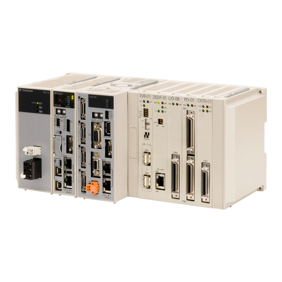
1.1 Definition of Terms MP3200 Definition of Terms This section defines terms that have specific meanings in this manual. MP3200 ”MP3200” is a collective term that refers to the four Units in the following table. Unit Name Primary Function Supplies the power that is needed for the operation of the Units that are connected Power Supply Unit to each other and to any Optional Modules that are connected in the Controller. -
Page 21: Racks
1.1 Definition of Terms Racks Racks A Rack is a set of Units that are connected to each other. Connection Example Power CPU Unit Optional Unit Base Unit Supply Unit Main Rack and Expansion Racks You can add Units and Optional Modules to a Rack to expand functionality. However, if a restriction such as the power supply capacity or number of Base Unit slots for one Rack is exceeded, you must add an Expansion Rack. - Page 22 1.1 Definition of Terms Main Rack and Expansion Racks *2. To mount the Unit with screws, use the JEPMC-OP3006-E or JEPMC-OP3007-E Rack Reinforcement Bracket. Refer to the following section for an expansion example. MP3200 Expansion Example (page 1-5)
- Page 23 1.1 Definition of Terms Main Rack and Expansion Racks MP3200 Expansion Example An MP3200 expansion example is given in the following figure. Rack Expansion Interface Unit EXIOIF Module Main Rack CPU Unit Expansion Racks (up to 6 Racks) EXIOIF Module EXIOIF Module EXIOIF Module MP2200 Base Unit...
-
Page 24: Rack Numbers
1.1 Definition of Terms Rack Numbers Rack Numbers When you add Expansion Racks, the MPE720 automatically assigns a number to each Rack so that the Racks can be identified. Rack No. Description Rack 1 Main Rack Rack 2 Rack 3 Expansion Racks added by using EXIOIF Modules Rack 4 The Expansion Rack that is connected to port 1 on the Rack Expansion... -
Page 25: Unit Numbers
1.1 Definition of Terms Unit Numbers Unit Numbers The MPE720 automatically assigns Unit numbers to the Units on each Rack so that the Units can be iden- tified. Numbers 1 to 5 are assigned to the Units in order from the left. Slot Numbers The MPE720 automatically assigns slot numbers to the slots on the Base Unit so that the slots can be iden- tified. -
Page 26: System Configuration Example
1.2 System Configuration Example System Configuration Example The following figure shows a typical system configuration. Refer to the following section for details on 1 to 11 in the following figure. 1.3 Devices and Components That Are Required to Build a System (page 1-9) MPE720 Integrated Optional Modules Engineering Tool Version 7... -
Page 27: Devices And Components That Are Required To Build A System
1.3 Devices and Components That Are Required to Build a System Devices and Components That Are Required to Build a System The following table lists the devices and components that are required to build the system that is shown in 1.2 System Configuration Example (page 1-8). - Page 28 1.3 Devices and Components That Are Required to Build a System Continued from previous page. Name Model Remarks Standard cable JEPMC-W6012- -E Length: 0.2 to 50 m Connects the CPU Unit Cable with ferrite cores MECHATROLINK- JEPMC-W6013- to MECHATROLINK-III III Cable -E Length: 10 to 50 m...
-
Page 29: Mp3200 Unit List
Precautions When Combining MP3200 Units (page 1-14) Note Maximum Abbrevia- Internal Unit Model Description tion Current Consumption − PSA-12 JEPMC-PSA3012-E AC power supply Power Supply Units − PSD-12 JEPMC-PSD3012-E DC power supply − CPU-201 JEPMC-CP3201-E 2,000 mA CPU Unit −... -
Page 30: Optional Modules
1.3 Devices and Components That Are Required to Build a System Optional Modules Optional Modules You can add the Optional Modules that are listed in the following table for as many open slots there are in the Base Unit. Observe all precautions when combining Optional Modules. Refer to the following section for details. Precautions When Combining Optional Modules (page 1-14) Note Maximum... - Page 31 1.3 Devices and Components That Are Required to Build a System Optional Modules Continued from previous page. Maximum Internal Unit Abbreviation Model Description Current Consumption 16 inputs, 16 sinking outputs, 1 pulse- LIO-01 JAPMC-IO2300-E 300 mA train input 16 inputs, 16 sourcing outputs, 1 pulse- LIO-02 JAPMC-IO2301-E 300 mA...
-
Page 32: Precautions When Combining Products
1.4 Precautions When Combining Products Precautions When Combining MP3200 Units Precautions When Combining Products The following precautions must be observed when combining the MP3200 Units and Optional Modules. Precautions When Combining MP3200 Units There are restrictions in the order in which you can connect the Units. Build the Rack by connecting each Unit in the order that is shown below. -
Page 33: Precautions When Setting The Parameters
1.5 Precautions When Setting the Parameters Precautions When Setting the Circuit Numbers Precautions When Setting the Parameters Observe the following precautions when setting the MP3200. Precautions When Setting the Circuit Numbers When assigning circuit numbers to the Motion Control and Communications Function Modules, the num- bers must be within the following ranges. -
Page 34: Appearances And Parts
Appearances and Parts This section describes the appearance and parts of the MP3200. Power Supply Units ..... . . 2-2 Appearance and Part Names . -
Page 35: Power Supply Units
2.1 Power Supply Units Appearance and Part Names Power Supply Units The Power Supply Unit supplies the connected Units and Optional Modules with the power needed to operate. There are two Power Supply Units available: an AC Power Supply Unit and a DC Power Supply Unit. -
Page 36: Connectors
2.1 Power Supply Units Connectors Connectors The Power Supply Unit has three connectors: RLYOUT, power supply, and Unit connectors. RLYOUT Connector This connector outputs the operating status of the CPU Unit. Model: 734-302 Pin Assignments Signal Label Description • Normal operation: Circuit closed. •... - Page 37 2.1 Power Supply Units Connectors Unit Connector This connector is used to connect the next Unit. Refer to the following manual for details on connecting Units. MP2000/MP3000 Series Machine Controller System Setup Manual (Manual No.: SIEP C880725 00)
-
Page 38: Cpu Unit
2.2 CPU Unit Appearance and Part Names CPU Unit The CPU Unit stores the module definitions and programs, and interprets the programs. The CPU Unit also controls the Optional Modules. This section shows the appearance and part names of the CPU Unit and describes the indicators, switches, connectors, Fan, and temperature sensor. -
Page 39: Display And Indicators
2.2 CPU Unit Display and Indicators Display and Indicators The CPU Unit has the following display and four indicators. • Display • Status indicators • USB status indicator • MECHATROLINK-III status indicators • Ethernet status indicators Display The display shows the execution or error status of the CPU Unit. Color Display Status... - Page 40 2.2 CPU Unit Display and Indicators Status Indicators These indicators show the status of the CPU Unit. Indicator Name Color Status When Lit* Green Operation is normal. Green A user program is being executed. An alarm occurred. An error occurred. The battery alarm occurred.
- Page 41 2.2 CPU Unit Display and Indicators Ethernet Status Indicators These indicators show the status of Ethernet communications. LINK/ACT 100M LINK/ACT 100M Indicator Name Color Status When Not Lit, Lit, or Flashing Lit: Ethernet link established. LINK/ACT Yellow Flashing: Ethernet communications activity. Not lit: 10 M connection 100M Green...
-
Page 42: Switches
2.2 CPU Unit Switches Switches The CPU Unit has the following four switches. • DIP switch: Mode switch 1 • DIP switch: Mode switch 2 • Rotary switches • STOP/SAVE switch DIP Switch: Mode Switch 1 This DIP switch primarily sets the operating mode of the CPU Unit. Pin Name Status Operating Mode Default... - Page 43 2.2 CPU Unit Switches DIP Switch: Mode Switch 2 This DIP switch primarily sets the operating mode of the CPU Unit. Pin Name Status Operating Mode Default Remarks Reserved for system. E-PM0 Keep this pin OFF at all times. Normal operation Reserved for system.
-
Page 44: Connectors
2.2 CPU Unit Connectors STOP/SAVE Switch This switch is used when removing the USB memory device, or when batch saving data to the USB mem- ory. STOP/SAVE switch Open the cover. • Lightly press this switch to prepare the USB memory device for removal. The USB memory device can be safely removed when the USB status indicator changes from flashing to not lit. -
Page 45: Fan
2.2 CPU Unit USB Connector This connector is used to connect a USB memory device. USB connector Open the cover. Before removing the USB memory device, press the STOP/SAVE switch and wait until the USB status indicator goes out. If the USB memory device is removed while the USB status indicator is lit or flash- ing, the data may become corrupted. -
Page 46: Temperature Sensor
2.2 CPU Unit Temperature Sensor There are three levels of alarms, as shown in the following table. Display ALM Indicator Error Description A.240 A Fan operation failure was detected. The Fan remained stopped for more than a minute after A.240 was detected. E.083 (The CPU Unit will stop.) The failsafe function was activated for E.083 (Fan Alarm) or E.082 (Tem-... -
Page 47: Base Units
2.3 Base Units Appearance and Part Names Base Units The Base Unit is used to mount Optional Modules. There are three models of Base Units, a three-slot model, a five-slot model, and an eight-slot model. This section shows the appearance and part names of the Base Unit and describes the connector. Appearance and Part Names The following figure shows the appearance of the Base Unit and a part name. -
Page 48: Rack Expansion Interface Unit
2.4 Rack Expansion Interface Unit Appearance and Part Names Rack Expansion Interface Unit A Rack Expansion Interface Unit is used to expand a Rack. There are two models of Rack Expansion Interface Units, a Main Rack Expansion Interface Unit and an Expansion Rack Expansion Interface Unit. This section shows the appearance and part names of the Rack Expansion Interface Units and describes the indicators and connectors. -
Page 49: Indicators
2.4 Rack Expansion Interface Unit Indicators Indicators These indicators show the operating status of the Rack Expansion Interface Unit, the communications sta- tus of the cable, and the error status. For Main Rack For Expansion Rack 次回用 次 回 用 Indicator Color Status When Lit, Flashing, or Not Lit... -
Page 50: Connectors
2.4 Rack Expansion Interface Unit Connectors Connectors The Rack Expansion Interface Unit has two connectors: Rack Expansion Interface Unit connector and Unit connector. Rack Expansion Interface Unit Connector This connector is used to connect an Expansion Rack. The Main Rack Expansion Interface Unit has three connectors (port 1, port 2, and port 3), and the Expan- sion Rack Expansion Interface Unit has one connector (port 1). - Page 51 CPU Unit Functionality This chapter describes the functionality of the MP3200 CPU Units. Basic Functionality ......3-2 Programs .
-
Page 52: Basic Functionality
3.1 Basic Functionality Programs Basic Functionality This section describes the basic functionality of the CPU Unit. Programs A program is a list of instructions to be processed by the CPU Unit. This section describes the types of programs and gives an overview of each type. Types of Programs There are three types of user programs: •... - Page 53 3.1 Basic Functionality Programs The following table lists the priority, execution conditions, and maximum number of drawings for each type of ladder drawing. Maximum Drawing Type Priority* Execution Condition Number of Drawings Power ON (These drawings are executed once when DWG.A (Startup Drawings) the power supply is turned ON.) External interrupt (These drawings are executed...
- Page 54 3.1 Basic Functionality Programs DWG notation: DWG. Grandchild drawing number Child drawing number Parent drawing type (A, I, H, or L) Note: The following notation is used for operation error drawings. DWG. Fixed value (00) Parent drawing type (A, I, H, or L) of the drawing where the error occurs The breakdown of the number of ladder drawings in each category is given in the following table.
- Page 55 3.1 Basic Functionality Programs Execution Processing of Drawings The drawings are executed by calling them from the top to the bottom, following the hierarchy of the drawings. The following figure illustrates the execution processing of a high-speed scan drawing (DWG.H).
- Page 56 3.1 Basic Functionality Programs • Standard System Functions The following functions for communications and other purposes are provided as standard functions in the system. You cannot change the system functions. Function Name Name Used in MPE720 COUNTER Counter Counter FINFOUT First-in First-out First-in First-out TRACE...
- Page 57 3.1 Basic Functionality Programs Motion Subprograms Subprograms are created to perform common operations. They help minimizing the number of pro- gram steps and allow efficient use of memory. Terms Main program Main program Main program MPM001 MPM002 MPM003 Call (MSEE) Call (MSEE) Call (MSEE) The common...
- Page 58 3.1 Basic Functionality Programs Motion Program Execution Motion programs are called with an MSEE instruction from a ladder program in an H drawing. You can also register the motion program in the M-EXECUTOR (Motion Executor) to call it. Refer to the following section for details.
- Page 59 3.1 Basic Functionality Programs The following points must be taken into consideration when executing motion programs. • Motion programs that are registered in the M-EXECUTOR cannot be executed with MSEE instruc- tions. Note • More than one instance of the same motion program (i.e., the same program number) cannot be exe- cuted with MSEE instructions.
- Page 60 3.1 Basic Functionality Programs MPM003 ABS; MSEE Instruction MOV[X] _ [Y] _ Setting device MVS[X] _ [Y] _ F IOW MB0001 The value is stored in the MW00200 MOV[X] _ [Y] _ register. Register address MW00200 = 3 Ladder Program Motion Program ...
- Page 61 3.1 Basic Functionality Programs Continued from previous page. Bit No. Name Description − Bit 6 Reserved for system. − Bit 7 Reserved for system. This bit is set to 1 when a program alarm occurs. When this bit is set to 1, details on the error will be displayed in the Error Infor- mation Dialog Box and are given in the S registers.
- Page 62 3.1 Basic Functionality Programs • Control Signals To control the execution of a motion program, you must input program control signals (Request for Start of Program Operation, or Request for Stop of Program, etc.). The following table describes the control sig- nals for motion programs.
- Page 63 3.1 Basic Functionality Programs Continued from previous page. Bit No. Name Description To specify a system work number, set this bit to 1. Bit D System Work 0: Do not specify a system work number. Number Setting 1: Specify a system work number. To specify an interpolation override, set this bit to 1.
- Page 64 3.1 Basic Functionality Programs Timing chart examples for axis operations and status flags after a control signal is input are pro- Example vided below. Request for Start of Program Operation Control signal: Request for Start of Program Operation Status flag: Program Executing Axis operation: Pulse distribution Request for Pause Control signal: Request for Start of...
- Page 65 3.1 Basic Functionality Programs If a Motion Program Alarm Occurs Control signal: Request for Start of Program Operation Control signal: Program Reset and Alarm Reset Request Status flag: Program Executing Status flag: Program Alarm 1 scan* Axis operation: Pulse distribution for Interpolation instruction Axis operation: Pulse distribution for Positioning instruction...
- Page 66 3.1 Basic Functionality Programs When using MSEE instructions in ladder programs along with the M-EXECUTOR, do not specify the system work numbers that are for the M-EXECUTOR in the MSEE instructions in the ladder programs. If you specify one, a No System Work Error will occur. Important System work numbers for the M-EXECUTOR: 0 to the set value of the number of program definitions You cannot set the system work numbers when you use the M-EXECUTOR.
- Page 67 3.1 Basic Functionality Programs Sequence Programs A sequence program is written in a text-based motion language. There are two types of sequence programs. Designation Type Features Number of Programs Method SPM You can create up to 512 motion pro- Main programs are called from Main programs the M-EXECUTOR program...
- Page 68 3.1 Basic Functionality Programs Specifying Sequence Programs Sequence programs must be specified directly. Indirect designations cannot be used. Specify the program number of the sequence program to execute (SPM). Sequence program SPM001 M-EXECUTOR Program Execution Definitions IF MW000<32767; MW000=MW000+1; ELSE;...
-
Page 69: Registers
3.1 Basic Functionality Registers Registers Registers are areas that store data within the Machine Controller. Variables are registers with labels (vari- able names). There are two kinds of registers: global registers that are shared between all programs, and local registered that are used only by a specific program. - Page 70 3.1 Basic Functionality Registers Motion Program Conceptual Diagram Sequence program Motion program (SPM003) (MPM001) Subprogram Subprogram MSEE MPS002; SSEE SPS004; (MPS002) (SPS004) D registers D registers D registers D registers (DW00000 (DW00000 (DW00000 (DW00000 DW00031) DW00031) DW00031) DW00031) D registers cannot be shared between D registers cannot be shared between different drawings.
- Page 71 3.1 Basic Functionality Registers Continued from previous page. Designation Type Name Usable Range Description Method GBnnnnnnnh, GWnnnnnnn, GLnnnnnnn, These registers are used as interfaces between pro- GW0000000 to grams. G registers GQnnnnnnn, GW2097151 GFnnnnnnn, They do not have a battery backup. GDnnnnnnn, GAnnnnnnn IW00000 to...
- Page 72 3.1 Basic Functionality Registers Local Registers Local registers are valid within only one specific program. The local registers in other programs cannot be accessed. You specify the usable range from the MPE720. Designation Type Name Description Features Method #Bnnnnnh, #Wnnnnn, #Lnnnnn, These registers can be read in programs but they cannot be...
- Page 73 3.1 Basic Functionality Registers User functions can be called from any programs, any number of times. Important Precautions When Using Local Registers within a User Function When you call a user function, consider what values could be in the local registers, and perform initializa- tion as needed.
- Page 74 3.1 Basic Functionality Registers Data Types There are various data types that you can use depending on the purpose of the application: bit, integer, double-length integer, quadruple-length integer, real number, double-precision real number, and address. Symbol Data Type Range of Values Data Size Description Used in relay circuits and to...
- Page 75 3.1 Basic Functionality Registers Data Types and Register Designations An extra digit that specifies the bit (3) is appended One word is allocated for to the end of the register address (0000100). each register address. Integer data type [MB00001003] Bit data type Address data type [MW0000100] [ML0000100]...
- Page 76 3.1 Basic Functionality Registers Precautions for Operations Using Different Data Types If you perform an operation using different data types, be aware that the results will be different depending on the data type of the storage register, as described below. •...
- Page 77 3.1 Basic Functionality Registers The data is little endian, as shown in the following example. Information • MB00001006 MB00001006 MW0000100 • MW0000100 = 1234 hex MW0000100 1234 hex • ML0000100 = 12345678 hex MW0000100 5678 hex ML0000100 MW0000101 1234 hex •...
- Page 78 3.1 Basic Functionality Registers Attaching an Index to a Bit Register Using an index is the same as adding the value of i or j to the register address. For example, if i = 2, MB00000000i is the same as MB00000002. i = 2;...
- Page 79 3.1 Basic Functionality Registers Attaching an Index to a Quadruple-length Integer or a Double-precision Real Number Register Using an index is the same as adding the value of i or j to the register address. For example, if j = 2, MQ0000000j is the same as MQ0000002. Similarly, if j = 2, MD0000000j is the same as MD0000002.
- Page 80 3.1 Basic Functionality Registers Array Registers ([ ]) Array registers are used to modify register addresses, and are denoted by square brackets [ ]. These are used to handle register addresses like variables. Similarly to index registers, an offset is added to the register address. ...
-
Page 81: Execution Scheduling
3.1 Basic Functionality Execution Scheduling Execution Scheduling This section describes the execution order of drawings. Controlling the Execution of Drawings Drawings are executed based on their priorities, as shown in the following figure. Power ON DWG.A (Startup Drawings) Interrupt signal Every high-speed scan Every low-speed scan Batch output... -
Page 82: Scans
3.1 Basic Functionality Scans Scans A scan refers to the processing that starts at fixed intervals. This section describes the scans. Types of Scans The CPU Unit has two types of scans, the high-speed H scan and low-speed L scan. A high-speed H scan has higher priority than a low-speed L scan. - Page 83 3.1 Basic Functionality Scans Continued from previous page. Possible Set Values Communica- High-speed Scan Time Set When MP2000 Optional When MP2000 Optional tions Cycle Value Restrictions Module Is Not Used Module Is Used Integral multiple of 2 ms or 1 2.0 to 32.0 ms (in increments 2.0 to 32.0 ms (in increments 2 ms...
- Page 84 3.1 Basic Functionality Scans Example: High-speed Scan Time Set to 0.250 ms 0.5 ms 0.25 ms High-speed scan Basic cycle (0.5 ms) Reference Reference issued at Reference issued at issued at MP2000 Optional Module System service register SB000008* * The purpose of this system service register is to determine from a ladder program whether the I/O scan service is being executed for MP2000 Optional Modules ...
- Page 85 3.1 Basic Functionality Scans − Select File Environment Setting from the menu bar. Alternatively, click the System Setting Icon on the Start Tab Page. The Environment Setting Dialog Box will be displayed. − Select Setup Scan Time Setting. The following dialog box will be displayed. Setting Value: Enter the scan time settings.
- Page 86 3.1 Basic Functionality Scans Keep Latest Value Setting in High-speed/Low-speed Scans You can use the Keep Latest Value setting to specify the number of scans to hold previous data when an input error occurs. If the input error still exists after the number of scans specified for the Keep Latest Value setting, the input values will be treated as 0.
- Page 87 3.1 Basic Functionality Scans Click the OK Button. The settings will be saved and the Environment Setting Dialog Box will close. The Keep Latest Value setting specifies the number of scans to process before the I/O service Information clears the input registers. If the high-speed scan time setting is set to 0.250 ms or 0.125 ms, the scan at which the input reg- isters are cleared will differ for the MP2000-series Optional Module and the 218IFD and SVC32 Function Modules that are built into the CPU Unit.
-
Page 88: Function Modules
3.2 Function Modules Self Configuration Function Modules This section describes the Function Modules that are built into the CPU Unit. Self Configuration Self configuration is a feature that automatically recognizes all the Optional Modules that are installed in the Machine Controller and all the slave devices that are connected via the MECHATROLINK connector (such as Servo Drives), and creates the module configuration definition files based on that information. - Page 89 3.2 Function Modules Self Configuration Operating Procedures This section describes the procedures for executing self configuration. • Refer to the following section when you perform self configuration for the first time after connecting the devices. Self Configuration Using the DIP Switch (page 3-39) •...
- Page 90 3.2 Function Modules Self Configuration Turn OFF the INIT and CNFG pins on the SW1 DIP switch on the CPU Unit. 1. INIT Pin on the DIP Switch and RAM Data If the power supply is turned OFF and ON again when the INIT pin on the Machine Controller SW1 DIP switch is turned ON, the data in RAM will be cleared.
- Page 91 3.2 Function Modules Self Configuration Confirm that the status indicators on the CPU Unit change in the following way: • RDY: Goes out, and then lights. • RUN: Goes out, flashes, and then lights. Turn OFF the CNFG pin on the SW1 DIP switch on the CPU Unit. Power Interruptions after Self Configuration After performing self configuration, turn OFF the power supply to the Machine Controller only after the definition data is saved to the flash memory of the Machine Controller.
- Page 92 3.2 Function Modules Self Configuration Self Configuration Using the MPE720 There are two types of self configuration that can be performed with the MPE720. • Self configuration of all Modules: Use this mode when the system is being set up for the first time, or after the entire system has been changed.
- Page 93 3.2 Function Modules Self Configuration Click the Module Button. Click the All modules Button on the Launcher. The MC-Configurator Dialog Box will be displayed. Click the OK Button. Self configuration will be executed. 3-43...
- Page 94 3.2 Function Modules Self Configuration Self Configuration of Specified Modules Before performing this procedure, turn ON the power supply to the SERVOPACKs and other devices. Important Important Click the Module Configuration Icon on the Start Tab Page. The following Module Configuration Definition Tab Page will be displayed. In the Function Module/Slave Column, select the Modules to configure using self configuration.
- Page 95 3.2 Function Modules Self Configuration Click the specified module Button on the Launcher. The MC-Configurator Dialog Box will be displayed. Click the OK Button. Self configuration will be executed only for the new devices that are detected by MECHATROLINK com- munications.
- Page 96 3.2 Function Modules Self Configuration Definition Information Updated by Self Configuration The definition information that is updated by self configuration is described below. This procedure will not update any of the definitions that were made for existing devices and Function Modules.
- Page 97 3.2 Function Modules Self Configuration MECHATROLINK Communications Definition When Set as the Master Item Settings after Self Configuration Master/Slave Master My station address 0×0001 250 μs Communication Cycle Message Communications Enabled Number of Retry to Slaves Number of connection Slave synchronous function Disabled ...
-
Page 98: Communications Function Module (218Ifd)
3.2 Function Modules Communications Function Module (218IFD) Communications Function Module (218IFD) This Function Module is used for communications with a host device. The following table describes the communication features. Function Module Features Remarks The MP3000 Controller supports multiple • Supported Protocols protocols to enable general-purpose Ether- MODBUS/TCP, OMRON, MELSEC A- Ethernet... - Page 99 3.2 Function Modules Communications Function Module (218IFD) The following Module Configuration Definition Tab Page will be displayed. Cells for 218IFD settings Double-click the 218IFD cell. The 218IFD Detail Definition Dialog Box will be displayed. Refer to the following manual for details on settings. MP3000 Series Communications User’s Manual (Manual No.: SIEP C880725 12) 3-49...
-
Page 100: Motion Control Function Modules (Svc32 And Svr32)
3.2 Function Modules Motion Control Function Modules (SVC32 and SVR32) Motion Control Function Modules (SVC32 and SVR32) The Motion Control Function Module is used for communications with a MECHATROLINK communica- tions device. There are two Motion Control Function Modules, the SVC32 and SVR32. Both Modules can provide the following forms of motion control. - Page 101 3.2 Function Modules Motion Control Function Modules (SVC32 and SVR32) Click the Module Configuration Icon on the Start Tab Page. The following Module Configuration Definition Tab Page will be displayed. Cells for SVC32 settings Cells for SVR32 settings 3-51...
- Page 102 3.2 Function Modules Motion Control Function Modules (SVC32 and SVR32) Double-click the SVC32 cell in the Module Configuration Definition Tab Page. The MECHATROLINK Communications Definition Dialog Box is displayed. If more than one Module is mounted, select the Module to be checked or set. Information Set the MECHATROLINK communications definitions as required.
- Page 103 3.2 Function Modules Motion Control Function Modules (SVC32 and SVR32) Select View − Work Space from the menu bar. The Work Space Pane is displayed on the left side of the MC-Configurator Window. Click the Expand [+] Button beside each program in the Work Space Pane to display motion parameters as shown below.
- Page 104 3.2 Function Modules Motion Control Function Modules (SVC32 and SVR32) Double-click the motion parameter to set or monitor. The Axis Display Selection Dialog Box (“Display in axis selected”) will be displayed. Select the axis to set or monitor, and then click the OK Button. The SVC Definition Tab Page for the selected motion parameters will be displayed.
- Page 105 3.2 Function Modules Motion Control Function Modules (SVC32 and SVR32) • Setting/Monitor Parameters Tab Page • Servo/Servo Monitor Parameters Tab Page Set the SVC definitions as required. Refer to the following manual for details on settings. MP3000 Series Motion Control User’s Manual (Manual No.: SIEP C880725 11) 3-55...
-
Page 106: The M-Executor
3.2 Function Modules The M-EXECUTOR The M-EXECUTOR This section describes the functionality of the M-EXECUTOR Motion Executor and the contents of its various displays. The M-EXECUTOR is a software module that executes motion and sequence programs. Terms Introduction The M-EXECUTOR provides the following merits: •... - Page 107 3.2 Function Modules The M-EXECUTOR Initializing the M-EXECUTOR Use the following procedure to initialize the M-EXECUTOR. Click the Module Configuration Icon on the Start Tab Page. The Module Configuration Definition Tab Page will be displayed. 3-57...
- Page 108 3.2 Function Modules The M-EXECUTOR Double-click the M-EXECUTOR cell. The M-EXECUTOR Definition Dialog Box will be displayed. 3-58...
- Page 109 3.2 Function Modules The M-EXECUTOR Click the OK Button. The Detail Definition Dialog Box will be displayed. Select File − Save from the toolbar. The M-EXECUTOR definitions will be saved. 3-59...
- Page 110 3.2 Function Modules The M-EXECUTOR M-EXECUTOR Detail Settings The detailed settings for the M-EXECUTOR are performed on the Module Configuration Tab Page and the Detail Definition Dialog Box. This section provides the procedures to display this tab page and dialog box, and describes their contents. ...
- Page 111 3.2 Function Modules The M-EXECUTOR The following table describes the M-EXECUTOR items that are displayed on the Module Configuration Definition Tab Page. Item Display/Setting Item Editing Displays whether the M-EXECUTOR is enabled. Function Module/Slave • UNDEFINED: Disabled Possible • M-EXECUTOR: Enabled ...
- Page 112 3.2 Function Modules The M-EXECUTOR Details on the I/O Registers The I/O registers that are assigned to the M-EXECUTOR are used to execute motion and sequence pro- grams, as well as to monitor sequence programs. The following tables give the contents of the M-EXECUTOR I/O registers. M-EXECUTOR Input Registers M-EXECUTOR Output Registers M-EXECUTOR...
- Page 113 3.2 Function Modules The M-EXECUTOR Program Definition Tab Page Register the motion or sequence programs to execute. This section describes the items that are displayed on the Program Definition Tab Page. ...
- Page 114 3.2 Function Modules The M-EXECUTOR Setting Set the program designation method. The designation method can be different for each program. Designation Motion Sequence Description Method Programs Programs The program is specified with the program number. Direct Possible Possible designation Examples: MPM001 or SPM002 The program is specified by specifying a register that contains the program number.
- Page 115 3.2 Function Modules The M-EXECUTOR Allocation Control Register Tab Page This tab page is used to assign registers. This section describes the items that are displayed on the Allocation Control Register Tab Page. ...
- Page 116 3.2 Function Modules The M-EXECUTOR Allocation Contact Interlock This contact controls copying data between the assigned registers and the M-EXECUTOR control registers. When the assigned interlock contact is ON, the data in the assigned registers and the M-EXECUTOR control registers is copied in the direction that is given by the arrow in the Direction Column ().
- Page 117 3.2 Function Modules The M-EXECUTOR Registering Program Execution This section gives the procedure to register the execution of programs. Display the program to register for execution. Click the Task Allocation ( ) Icon. The Task Allocation Dialog Box will be displayed. You can also use the Task Allocation Dialog Box to change the settings.
- Page 118 3.2 Function Modules The M-EXECUTOR Execution Scheduling Programs that are registered in the M-EXECUTOR are executed in the order of their priority levels (exe- cution types). Programs that are registered in the M-EXECUTOR are executed immediately before processing the ladder programs.
- Page 119 3.2 Function Modules The M-EXECUTOR The following is an execution example. • M-EXECUTOR Program Execution Definitions Sequence Program Execution Example Example The following figure shows an example of the sequence programs registered in the M- EXECUTOR. Execution Timing This section describes the execution timing of programs in the above example. The following figure shows program and drawing execution that is based on the order of registration in the M-EXECUTOR program definitions.
-
Page 120: Data Logging
3.2 Function Modules Data Logging Data Logging Data logging saves the values of specified registers in a log file according to the preset trigger timing and conditions. The data is stored in the RAM in the CPU Unit or on the USB memory device. Data Storage Location Merits Demerits... - Page 121 3.2 Function Modules Data Logging The Logging 1 Dialog Box will be displayed. Click the Format Button. The Format Dialog Box will be displayed. Set the format. 3-71...
- Page 122 3.2 Function Modules Data Logging Select the storage location. Setting Description In the built-in RAM disk Writes the sampled data to the built-in RAM disk in the CPU Unit. USB memory Writes the sampled data to the USB memory device in the CPU Unit. Select the file format.
- Page 123 3.2 Function Modules Data Logging Select whether to add date information to the folder name. • To omit date information, clear the selection of the check box. • To add date information, select the check box and select the date format from the list. Setting Description Adds the year to the specified folder name.
- Page 124 3.2 Function Modules Data Logging Set the file overwrite settings. Setting Description When the file number reaches the upper limit on the specified number of output Overwrite files, older files will be deleted to allow the creation of new files. When the file number reaches the upper limit of the specified number of output Stop logging files, logging will stop.
- Page 125 3.2 Function Modules Data Logging Continued from previous page. Item Description Removes the selected registers from the list of registers to be Delete Button logged. Displays a list of the registers that will be logged. Registers can be added to this list either by selecting them from the Logging Target List or by entering them directly.
- Page 126 3.2 Function Modules Data Logging Set the sampling and trigger settings. Set the logging name. • Maximum name length: 32 characters Set the data sampling rate. Setting Description Samples data synchronized with the high-speed scan. High-speed scan Data is sampled immediately after completing execution of the DWG.H ladder program.
- Page 127 3.2 Function Modules Data Logging to Set the logging conditions using items to Item Description If the check box is selected, register operation will control when logging starts. If conditions are set in items and , logging will start when these Specify the start ...
- Page 128 3.2 Function Modules Data Logging To automatically start logging when the power supply is turned ON, set the Start Trigger to Example the following condition. • When the saving destination is set to USB memory: Setting example: Start trigger SB006540 = ON Note: The SB006540 register turns ON when a USB memory device is detected.
- Page 129 3.2 Function Modules Data Logging Click the Start Button in the Logging 1 Dialog Box. Logging starts. While logging is in progress, the following items are displayed in the Logging 1 Dialog Box. • File update counter • Latest record number •...
- Page 130 3.2 Function Modules Data Logging Scan Setting Guidelines This section describes guidelines for the scan settings based on when data is logged. If Logging Is Synchronous with the Scan The general logging overhead is given below. Set the scan setting to a value that is larger than this value. Data Items 1 to 8 9 to 60...
- Page 131 3.2 Function Modules Data Logging High-speed scan cycle Current high-speed scan time This process samples target data and loads it into a logging buffer. Logging Logging (data (data DWG.H DWG.H High-speed scan sampling) sampling) Low-speed scan cycle Current low-speed scan time This process samples target data and loads it into a logging buffer.
- Page 132 3.2 Function Modules Data Logging Analyzing Log Data This section describes how the log data is formatted when viewed on a PC. CSV File Format This example shows how log data that is stored in the CSV format appears when it is opened in Microsoft Excel.
- Page 133 3.2 Function Modules Data Logging Binary File Format This example shows how log data that was stored in the binary format appears when it is opened in a text editor. Header The header is given in ASCII characters. Item Description Corresponding Item in MPE720...
- Page 134 3.2 Function Modules Data Logging The following example shows how the register data is given for the settings and conditions Example listed below. File Details to Output • Data No. and DATE/TIME are selected Target Register to Log • MW00000 Status •...
-
Page 135: Usb Memory
3.2 Function Modules USB Memory USB Memory You can transfer user application data between the RAM in the CPU Unit and the USB memory device. Operation Description Reference Loads all of the user application data that is saved in the USB memory device to ... - Page 136 3.2 Function Modules USB Memory Set the INIT pin on the mode switch 1 on the CPU Unit according to the register type to load. INIT Switch Setting Registers to Load M registers Transferred. Not transferred. G registers S registers Not transferred regardless of DIP switch setting.
- Page 137 3.2 Function Modules USB Memory Set the INIT pin on the mode switch 1 on the CPU Unit according to the register type to save. INIT Switch Setting Registers to Load M registers Transferred. Not transferred. G registers Transferred. Not transferred. S registers Transferred.
- Page 138 3.2 Function Modules USB Memory Alarm History File This section describes the data that is displayed when an alarm history file is checked on a PC. Alarm History File Format The following example shows how the CSV file is displayed when it is opened in a text editor. No,Alarm Code,Alarm Detail Format,Date,Rack,Unit,Slot,Detail1,Detail2,Detail3,Detail4,Detail5 1,A101H,I/O error,2000/01/01 00:00_40s,1,0,0,0000H,0000H,0000H,0000H,0000H 2,A30BH,Other error,2000/01/01 00:00_56s,1,0,0,0000H,0000H,0000H,0000H,0000H...
-
Page 139: File Transfer
3.2 Function Modules File Transfer File Transfer The functionality of an FTP server is provided so that you can transfer data between the RAM in the CPU Unit or the USB memory device and a remote device capable of acting as an FTP client. Data to Transfer Transfer Direction Remarks Reference... - Page 140 3.2 Function Modules File Transfer Default The default settings of an FTP account are given below. User Name Password FTP Privileges USER-A USER-A * R: Files can be read from the FTP client. W: Files can be written from the FTP client. ...
- Page 141 3.2 Function Modules File Transfer Set the FTP account information in the User Registration Dialog Box. Item Description Remarks This is the name that the FTP client on • You can enter up to 16 characters. User Name the remote device must use to log in to •...
- Page 142 3.2 Function Modules File Transfer FTP Privileges and Applicable FTP Commands FTP Privileges Item Command Description Disconnects and terminates the connection with the FTP server. Disconnects the connection with the FTP close server. Connection/Disconnec- open ...
-
Page 143: Security
3.2 Function Modules Security Press the Enter Key. The folder of the FTP server will be displayed. That is, the contents of the USB memory device connected to the CPU Unit is displayed. Security Security can be used to perform the following tasks. •... -
Page 144: Multi-Cpu Functions
3.3 Multi-CPU Functions Differences between Sub CPU Synchronization and Slave CPU Synchronization Multi-CPU Functions The multi-CPU functions allow you to use more than one CPU Unit to control one system. When you use more than one CPU Unit (i.e., when you use a multi-CPU function), you can divide the application programming of the Machine Controller. -
Page 145: Sub Cpu Synchronization
3.3 Multi-CPU Functions Sub CPU Synchronization Sub CPU Synchronization The following information is provided. Overview of Sub CPU Synchronization (page 3-95) Conditions for Using Sub CPU Synchronization (page 3-97) Precautions When Using Sub CPU Synchronization (page 3-98) Differences between the Main CPU Unit and Sub CPU Units (page 3-102) I/O Registers Used for Sub CPU Synchronization (page 3-104) Sub CPU Synchronization Data Transfer Timing (page 3-107) Scan Overhead Guidelines When Using Sub CPU Synchronization (page 3-108) - Page 146 3.3 Multi-CPU Functions Sub CPU Synchronization Main CPU Unit Sub CPU Unit 1 Base Unit with Optional Base Unit with Optional Modules mounted: Controlled Modules mounted: Controlled by Main CPU Unit by Sub CPU Unit 1. Sub CPU Unit 2 Base Unit with Optional Modules mounted: Controlled Sub CPU Unit 3...
- Page 147 3.3 Multi-CPU Functions Sub CPU Synchronization • You can have one Sub CPU Unit on the Main Rack and a total of three Sub CPU Units on Expansion Racks. You can therefore connect up to four Sub CPU Units in one system. •...
- Page 148 3.3 Multi-CPU Functions Sub CPU Synchronization Scan Set Values The settings of the high-speed scans of the CPU Units must satisfy one of the following equations. • High-speed scan set value of Main CPU Unit = High-speed scan set values of Sub CPU Units •...
- Page 149 3.3 Multi-CPU Functions Sub CPU Synchronization Behavior when CPU Units Stop CPU Run/CPU Stop Setting CPU Run/CPU Stop Status Main CPU Unit Setting Sub CPU Unit Setting Main CPU Unit Status Sub CPU Unit Status Stop Stop Stop Stop Stop Stop Stop...
- Page 150 3.3 Multi-CPU Functions Sub CPU Synchronization Connecting the MPE720 You can simultaneously connect up to two PCs running the MPE720 directly to a Sub CPU Unit. If you connect the MPE720 to Sub CPU Units through the Main CPU Unit, the MPE720 can successfully communicate with up to two Sub CPU Units at the same time.
- Page 151 3.3 Multi-CPU Functions Sub CPU Synchronization MPE720 Project File Management Manage all of the project files for the Main CPU Unit and Sub CPU Units as separate files. YMW7 file for YMW7 file for Main CPU Unit Sub CPU Unit 1 Main CPU Unit Sub CPU Unit 1 Sub CPU Unit 2...
- Page 152 3.3 Multi-CPU Functions Sub CPU Synchronization Although the Main CPU Unit and Sub CPU Units will have the same calender settings after the Information power supply is turned ON, thereafter they run on their own power supplies. This can cause error to occur between the calendar settings of the Main CPU Unit and Sub CPU Units as time passes.
- Page 153 3.3 Multi-CPU Functions Sub CPU Synchronization Continued from previous page. Item Main CPU Unit Sub CPU Unit • The Main CPU Unit connects directly to the MPE720 through the Ethernet connector on the Main CPU Unit. Direct connection with MPE720 with MPE720 Connections Ethernet connector on Main CPU •...
- Page 154 3.3 Multi-CPU Functions Sub CPU Synchronization I/O Registers Used for Sub CPU Synchronization There are the following two types of registers for the Main CPU Unit and Sub CPU Units. • High-speed scan CPU interface registers: Exchange data in the high-speed scan. •...
- Page 155 3.3 Multi-CPU Functions Sub CPU Synchronization CPU Interface Registers for High-speed Scan When you set the circuit number on the Module Configuration Definition Tab Page, the ranges of CPU interfaces for the high-speed scan given in the following table are assigned. The default circuit number is You cannot set the same circuit number for more than one Sub CPU Unit on the Module Configu- Information ration Definition Tab Page for the Main CPU Unit.
- Page 156 3.3 Multi-CPU Functions Sub CPU Synchronization CPU Interface Registers for Low-speed Scan You can set register sizes of up to 2,048 words for both the input and output registers for the CPU interface registers for the low-speed scan. Set a value that is an integral multiple of 16 words (32 bits). The data transfer size is the smaller of the I/O sizes of the Main CPU Unit and Sub CPU Unit.
- Page 157 3.3 Multi-CPU Functions Sub CPU Synchronization Sub CPU Synchronization Data Transfer Timing This section describes the timing of data transfer for the CPU interface registers for the high-speed and low-speed scans. CPU Interface Registers for High-speed Scan The following figures show the data transfer timing for CPU interface registers for the high-speed scans. ...
-
Page 158: Slave Cpu Synchronization
3.3 Multi-CPU Functions Slave CPU Synchronization Scan Overhead Guidelines When Using Sub CPU Synchronization This section provides guidelines for the scan overhead times for the sizes of CPU interface registers for high-speed and low-speed scans. CPU Interface Registers for High-speed Scan This section describes the data transfer timing for CPU interface registers for the high-speed scans. -
Page 159: Specifications
Specifications This section provides the installation and usage conditions of the MP3200. It also provides detailed specifications of the MP3200. MP3200 Installation and Usage Conditions ..4-2 Control Panel Cooling Method ......4-2 Power Supply Unit Specifications . -
Page 160: Mp3200 Installation And Usage Conditions
4.1 MP3200 Installation and Usage Conditions Control Panel Cooling Method MP3200 Installation and Usage Conditions The installation and usage conditions for the MP3200 are given in the following table. Item Specification Ambient Operating Temperature 0 to 55°C Ambient Storage Temperature -25 to 85°C Ambient Operating Humidity 30% to 95% RH (with no condensation) - Page 161 4.1 MP3200 Installation and Usage Conditions Control Panel Cooling Method Control Panels with Natural Cooling • Do not mount the Machine Controller at the top of the control panel, where the hot air that is generated inside the panel collects. •...
-
Page 162: Power Supply Unit Specifications
4.2 Power Supply Unit Specifications Power Supply Unit Specifications The specifications of the Power Supply Unit are given in the following table. Specification Item AC Power Supply Unit DC Power Supply Unit Model JEPMC-PSA3012-E JEPMC-PSD3012-E Abbreviation PSA-12 PSD-12 Input Voltage 100/200 VAC 24 VDC... -
Page 163: Cpu Unit Specifications
4.3 CPU Unit Specifications Hardware Specifications CPU Unit Specifications This section provides the specifications that are related to the performance, hardware, functionality, and registers of the CPU Unit. Hardware Specifications The hardware specifications of the CPU Unit are given in the following table. Item Specification Model... -
Page 164: Performance Specifications
4.3 CPU Unit Specifications Performance Specifications Performance Specifications The performance specifications of the CPU Unit are given in the following table. Specification Item Remarks CPU-201 CPU-202 • Main Rack • Expansion Racks added by using Maximum Number of EXIOIF Modules: 3 max. Racks •... - Page 165 4.3 CPU Unit Specifications Performance Specifications Continued from previous page. Specification Item Remarks CPU-201 CPU-202 Number of Startup Draw- ings (DWG.A) Number of Interrupt Draw- ings (DWG.I) Ladder Pro- Number of High-speed 1000 Number of steps per drawing: 4,000 grams Scan Drawings (DWG.H) Number of Low-speed 2000...
- Page 166 4.3 CPU Unit Specifications Performance Specifications Continued from previous page. Specification Item Remarks CPU-201 CPU-202 − Number of Groups − Trace Memory 1 Mword, 4 groups Traceable Data Points 16 points per group − Data Tracing >, <, =, <>, >=,<= and differential detection Trigger Types −...
-
Page 167: Communications Specifications
4.3 CPU Unit Specifications Communications Specifications Communications Specifications The specifications of the Communications Function Module that is built into the CPU Unit are given in the following table. Item Specification Remarks − Abbreviation 218IFD 10Base-T or Communications Interface − 100Base-TX Common Number of Communications Ports (Connec- 2-port hub... -
Page 168: Motion Control Function Module Specifications
4.3 CPU Unit Specifications Motion Control Function Module Specifications Motion Control Function Module Specifications The specifications of the Motion Control Function Module that is built into the CPU Unit are given in the following table. Specification Item Remarks CPU-201 CPU-202 −... -
Page 169: M-Executor Specifications
4.3 CPU Unit Specifications M-EXECUTOR Specifications M-EXECUTOR Specifications The specifications of the M-EXECUTOR in the CPU Unit are given in this section. Registerable Programs Program Type Number of Registered Programs Motion Programs Startup Interrupt Not possible. Sequence Programs H Scan L Scan * The combined total of motion programs and sequence programs must not exceed 32. -
Page 170: Usb Memory Specifications
− neously open files Formatting Not supported. Use a formatted USB memory device. Recommended USB Memory Device The following USB memory device is recommended. It can be purchased from Yaskawa. Model Specification Manufacturer SFU24096D1BP1TO-C-QT-111-CAP 4 GB USB memory Swissbit Japan Inc. - Page 171 4.3 CPU Unit Specifications System Register Specifications System Register Specifications This section provides the specifications of the system registers. Do not use the registers reserved for the system. Note Overall Configuration The following table shows the overall configuration of the system registers. You can read error information and the operating status of the system by specifying the system register address.
- Page 172 4.3 CPU Unit Specifications System Register Specifications Continued from previous page. Register Contents Details Address SW00800 to Module Information Module Information (page 4-29) SW01095 SW01096 to − Reserved for system. SW01410 SW01411 to MPU-01 Module Status MPU-01 Module Status (page 4-31) SW01442 SW01443 to −...
-
Page 173: System Register Specifications
4.3 CPU Unit Specifications System Register Specifications Details This section gives details on the system registers. System Service Registers The data in these registers give the execution status and specifications of the programs. The System Ser- vice Registers are reset to zero when the system is started. ... - Page 174 4.3 CPU Unit Specifications System Register Specifications DWG.H Only Operation starts when the high-speed scan starts. Register Address Name Remarks 1 scan SB000010 1-scan Flicker Relay 1 scan 0.5 s 0.5 s SB000011 0.5-s Flicker Relay 1.0 s 1.0 s SB000012 1.0-s Flicker Relay 2.0 s...
-
Page 175: System Register Specifications
4.3 CPU Unit Specifications System Register Specifications DWG.L Only Operation starts when the low-speed scan starts. Register Address Name Remarks 1 scan SB000030 1-scan Flicker Relay 1 scan 0.5 s 0.5 s SB000031 0.5-s Flicker Relay 1.0 s 1.0 s SB000032 1.0-s Flicker Relay 2.0 s... - Page 176 4.3 CPU Unit Specifications System Register Specifications System Execution Status Register Address Name Remarks SW00004 High-speed Scan Set Value High-speed scan set value (0.1 ms) SW00005 Current High-speed Scan Time Current high-speed scan time (0.1 ms) SW00006 Maximum High-speed Scan Time Maximum high-speed scan time (0.1 ms) SW00007 High-speed Scan Set Value 2...
- Page 177 4.3 CPU Unit Specifications System Register Specifications System Status The data in these registers give the operating status of the system or provide information about errors. You can check the following system registers to determine whether the cause of the error is hardware or soft- ware related.
- Page 178 4.3 CPU Unit Specifications System Register Specifications Continued from previous page. Name Register Address Contents H Scan Exceeded SW00044 H Scan Exceeded Count Counter L Scan Exceeded SW00046 L Scan Exceeded Count Counter Reserved for SB000470 to − SW00047 Reserved for system. system.
- Page 179 4.3 CPU Unit Specifications System Register Specifications Continued from previous page. Register Name Contents Address 0000 hex system 0001 hex DWG.A 0002 hex DWG.I Program Type SW00055 0003 hex DWG.H 0005 hex DWG.L 0008 hex Function 000F hex Motion program or sequence program FFFF hex Ladder program parent drawing 8000 hex...
- Page 180 4.3 CPU Unit Specifications System Register Specifications Continued from previous page. Register Name Contents Address SW00060 and Reserved for system. SW00061 SW00062 to Name of task that caused the error SW00065 SW00066 and Reserved for system. SW00067 SW00068 Year When Error Occurred SW00069 Month When Error Occurred SW00070...
- Page 181 4.3 CPU Unit Specifications System Register Specifications User Operation Error Code −1: Operation Errors Error Code Error Description Operation When an Error Occurs 0001 hex Integer operation underflow [-32768] 0002 hex Integer operation overflow [32767] 0003 hex Integer operation division error [The A register stays the same.] 0009 hex Double-length integer operation underflow...
- Page 182 4.3 CPU Unit Specifications System Register Specifications User Operation Error Code −2: Index Errors Error Code Error Description Operation When an Error Occurs Re-executed as if i and j were set to 0. (Both 1000 hex Index error in drawing i and j registers stay the same.) Re-executed as if i and j were set to 0.
- Page 183 4.3 CPU Unit Specifications System Register Specifications Detailed User Operation Error Status The data in these registers give details when a user operation error occurs in a user program. Register Address Name Remarks DWG.A DWG.I DWG.H DWG.L Error Count SW00110 SW00126 SW00142...
- Page 184 4.3 CPU Unit Specifications System Register Specifications System I/O Error Status The data in these registers give the I/O errors in the system for Racks 1 to 4. The details of the error status depend on the Modules that are mounted and the error code. Refer to the fol- lowing manual for details.
- Page 185 4.3 CPU Unit Specifications System Register Specifications USB-related System Status The data in these registers give information on the USB memory and give the error status. Name Register Address Remarks Available USB Memory SL00650 Unit: Kilobytes Total USB Memory SL00652 0: No USB memory device SB006540...
- Page 186 4.3 CPU Unit Specifications System Register Specifications Interrupt Status The data in these registers give the status of information provided by interrupts from each I/O Module. Register Configuration Name Register Address Remarks − Interrupt Detection Count SW00698 Module Where an Interrupt SW00699 Number of Modules with a single interrupt Occurred...
- Page 187 4.3 CPU Unit Specifications System Register Specifications Module Information The data in these registers give hardware information about the CPU Unit and Optional Modules on Racks 1 to 4. Name Register Address Remarks SW00800 CPU Module ID SW00801 Hardware version (BCD) SW00802 Software version (BCD) SW00803...
- Page 188 4.3 CPU Unit Specifications System Register Specifications Continued from previous page. Name Register Address Remarks SW00880 to SW00887 Slot 1 Same as above. SW00888 to SW00895 Slot 2 Same as above. SW00896 to SW00903 Slot 3 Same as above. SW00904 to SW00911 Slot 4 Same as above.
- Page 189 4.3 CPU Unit Specifications System Register Specifications MPU-01 Module Status The data in these registers give the status of the MPU-01 Multi-CPU Module. Register Name Contents Address SW01411 Status of MPU-01 Module circuit number 1 SW01412 Error status of MPU-01 Module circuit number 1 SW01413 Status of MPU-01 Module circuit number 2 SW01414...
- Page 190 4.3 CPU Unit Specifications System Register Specifications Motion Program Execution Information The data in these registers give the execution status of the motion programs. Register Configuration Register Address Name Reference − SW03200 Number of Currently Executing Program for Work 1 −...
- Page 191 4.3 CPU Unit Specifications System Register Specifications Continued from previous page. Register Address Name Reference SW03728 to SW03785 Work 9 Program Information SW03786 to SW03843 Work 10 Program Information SW03844 to SW03901 Work 11 Program Information SW03902 to SW03959 Work 12 Program Information System Work Numbers 9 to 16 (page 4-49) SW03960 to SW04017...
- Page 192 4.3 CPU Unit Specifications System Register Specifications Continued from previous page. Register Address Name Reference SW08960 to SW08991 Work 25 Extended Program Information SW08992 to SW09023 Work 26 Extended Program Information SW09024 to SW09055 Work 27 Extended Program Information SW09056 to SW09087 Work 28 Extended Program Information System Work Numbers 25 to 32 (page 4-53)
- Page 193 4.3 CPU Unit Specifications System Register Specifications Details The following table gives details on the Program Execution Bits from system register addresses SW03232 to SW03263. Register Address Contents SB032320 MPM001 or MPS001 SB032321 MPM002 or MPS002 SB032322 MPM003 or MPS003 SB032323 MPM004 or MPS004 SB032324...
- Page 194 4.3 CPU Unit Specifications System Register Specifications Continued from previous page. Register Address Contents SB032340 MPM033 or MPS033 SB032341 MPM034 or MPS034 SB032342 MPM035 or MPS035 SB032343 MPM036 or MPS036 SB032344 MPM037 or MPS037 SB032345 MPM038 or MPS038 SB032346 MPM039 or MPS039 SB032347 MPM040 or MPS040 SW03234...
- Page 195 4.3 CPU Unit Specifications System Register Specifications Continued from previous page. Register Address Contents SB032370 MPM081 or MPS081 SB032371 MPM082 or MPS082 SB032372 MPM083 or MPS083 SB032373 MPM084 or MPS084 SB032374 MPM085 or MPS085 SB032375 MPM086 or MPS086 SB032376 MPM087 or MPS087 SB032377 MPM088 or MPS088 SW03237...
- Page 196 4.3 CPU Unit Specifications System Register Specifications Continued from previous page. Register Address Contents SB032400 MPM129 or MPS129 SB032401 MPM130 or MPS130 SB032402 MPM131 or MPS131 SB032403 MPM132 or MPS132 SB032404 MPM133 or MPS133 SB032405 MPM134 or MPS134 SB032406 MPM135 or MPS135 SB032407 MPM136 or MPS136 SW03240...
- Page 197 4.3 CPU Unit Specifications System Register Specifications Continued from previous page. Register Address Contents SB032430 MPM177 or MPS177 SB032431 MPM178 or MPS178 SB032432 MPM179 or MPS179 SB032433 MPM180 or MPS180 SB032434 MPM181 or MPS181 SB032435 MPM182 or MPS182 SB032436 MPM183 or MPS183 SB032437 MPM184 or MPS184 SW03243...
- Page 198 4.3 CPU Unit Specifications System Register Specifications Continued from previous page. Register Address Contents SB032460 MPM225 or MPS225 SB032461 MPM226 or MPS226 SB032462 MPM227 or MPS227 SB032463 MPM228 or MPS228 SB032464 MPM229 or MPS229 SB032465 MPM230 or MPS230 SB032466 MPM231 or MPS231 SB032467 MPM232 or MPS232 SW03246...
- Page 199 4.3 CPU Unit Specifications System Register Specifications Continued from previous page. Register Address Contents SB032490 MPM273 or MPS273 SB032491 MPM274 or MPS274 SB032492 MPM275 or MPS275 SB032493 MPM276 or MPS276 SB032494 MPM277 or MPS277 SB032495 MPM278 or MPS278 SB032496 MPM279 or MPS279 SB032497 MPM280 or MPS280 SW03249...
- Page 200 4.3 CPU Unit Specifications System Register Specifications Continued from previous page. Register Address Contents SB032520 MPM321 or MPS321 SB032521 MPM322 or MPS322 SB032522 MPM323 or MPS323 SB032523 MPM324 or MPS324 SB032524 MPM325 or MPS325 SB032525 MPM326 or MPS326 SB032526 MPM327 or MPS327 SB032527 MPM328 or MPS328 SW03252...
- Page 201 4.3 CPU Unit Specifications System Register Specifications Continued from previous page. Register Address Contents SB032550 MPM369 or MPS369 SB032551 MPM370 or MPS370 SB032552 MPM371 or MPS371 SB032553 MPM372 or MPS372 SB032554 MPM373 or MPS373 SB032555 MPM374 or MPS374 SB032556 MPM375 or MPS375 SB032557 MPM376 or MPS376 SW03255...
- Page 202 4.3 CPU Unit Specifications System Register Specifications Continued from previous page. Register Address Contents SB032580 MPM417 or MPS417 SB032581 MPM418 or MPS418 SB032582 MPM419 or MPS419 SB032583 MPM420 or MPS420 SB032584 MPM421 or MPS421 SB032585 MPM422 or MPS422 SB032586 MPM423 or MPS423 SB032587 MPM424 or MPS424 SW03258...
- Page 203 4.3 CPU Unit Specifications System Register Specifications Continued from previous page. Register Address Contents SB032610 MPM465 or MPS465 SB032611 MPM466 or MPS466 SB032612 MPM467 or MPS467 SB032613 MPM468 or MPS468 SB032614 MPM469 or MPS469 SB032615 MPM470 or MPS470 SB032616 MPM471 or MPS471 SB032617 MPM472 or MPS472 SW03261...
- Page 204 4.3 CPU Unit Specifications System Register Specifications Registers Used for System Work Numbers 1 to 32 The registers that are used for system work numbers 1 to 32 are given in the following table. Two system registers are given in the register table for the alarm code, but we recommend that you use system registers SL26.
- Page 205 4.3 CPU Unit Specifications System Register Specifications Continued from previous page. System Work Work 1 Work 2 Work 3 Work 4 Work 5 Work 6 Work 7 Work 8 Number Logical Axis 3 Pro- SL03294 SL03352 SL03410 SL03468 SL03526 SL03584 SL03642 SL03700 gram Current Position...
- Page 206 4.3 CPU Unit Specifications System Register Specifications Continued from previous page. System Work Work 1 Work 2 Work 3 Work 4 Work 5 Work 6 Work 7 Work 8 Number Logical Axis 29 Pro- SL08216 SL08248 SL08280 SL08312 SL08344 SL08376 SL08408 SL08440 gram Current Position...
- Page 207 4.3 CPU Unit Specifications System Register Specifications • System Work Numbers 9 to 16 System Work Work 9 Work 10 Work 11 Work 12 Work 13 Work 14 Work 15 Work 16 Number Executing Main SW03208 SW03209 SW03210 SW03211 SW03212 SW03213 SW03214 SW03215 Program No.
- Page 208 4.3 CPU Unit Specifications System Register Specifications Continued from previous page. System Work Work 9 Work 10 Work 11 Work 12 Work 13 Work 14 Work 15 Work 16 Number Logical Axis 8 Pro- SL03768 SL03826 SL03884 SL03942 SL04000 SL04058 SL04116 SL04174 gram Current Position...
- Page 209 4.3 CPU Unit Specifications System Register Specifications • System Work Numbers 17 to 24 System Work Work 17 Work 18 Work 19 Work 20 Work 21 Work 22 Work 23 Work 24 Number Executing Main SW03216 SW03217 SW03218 SW03219 SW03220 SW03221 SW03222 SW03223 Program No.
- Page 210 4.3 CPU Unit Specifications System Register Specifications Continued from previous page. System Work Work 17 Work 18 Work 19 Work 20 Work 21 Work 22 Work 23 Work 24 Number Logical Axis 8 Pro- SL04232 SL04290 SL04348 SL04406 SL04464 SL04522 SL04580 SL04638 gram Current Position...
- Page 211 4.3 CPU Unit Specifications System Register Specifications • System Work Numbers 25 to 32 System Work Work 25 Work 26 Work 27 Work 28 Work 29 Work 30 Work 31 Work 32 Number Executing Main SW03224 SW03225 SW03226 SW03227 SW03228 SW03229 SW03230 SW03231 Program No.
- Page 212 4.3 CPU Unit Specifications System Register Specifications Continued from previous page. System Work Work 25 Work 26 Work 27 Work 28 Work 29 Work 30 Work 31 Work 32 Number Logical Axis 8 Pro- SL04696 SL04754 SL04812 SL04870 SL04928 SL04986 SL05044 SL05102 gram Current Position...
- Page 213 4.3 CPU Unit Specifications System Register Specifications Expansion System I/O Error Status The data in these registers give the I/O errors in the system for Racks 1 and 5 to 7. The details of the error status depend on the Modules that are mounted and the error code. Refer to the fol- lowing manual for details.
- Page 214 4.3 CPU Unit Specifications System Register Specifications Continued from previous page. Name Register Addresses Remarks SW10628 to SW10659 Slot 1 SW10660 to SW10691 Slot 2 SW10692 to SW10723 Slot 3 SW10724 to SW10755 Slot 4 Unit 1 SW10756 to SW10787 Slot 5 SW10788 to SW10819 Slot 6...
- Page 215 4.3 CPU Unit Specifications System Register Specifications Continued from previous page. Name Register Addresses Remarks SW11652 to SW11683 Slot 1 SW11684 to SW11715 Slot 2 SW11716 to SW11747 Slot 3 SW11748 to SW11779 Slot 4 Unit 1 SW11780 to SW11811 Slot 5 SW11812 to SW11843 Slot 6...
- Page 216 4.3 CPU Unit Specifications System Register Specifications Continued from previous page. Name Register Addresses Remarks SW12676 to SW12707 Slot 1 SW12708 to SW12739 Slot 2 SW12740 to SW12771 Slot 3 SW12772 to SW12803 Slot 4 Unit 1 SW12804 to SW12835 Slot 5 SW12836 to SW12867 Slot 6...
- Page 217 4.3 CPU Unit Specifications System Register Specifications Expanded Unit and Module Information The data in these registers give hardware information about the CPU Unit and Optional Modules on Racks 1 and 5 to 7. Name Register Addresses Remarks SW13700 CPU Unit ID (Low) SW13701 CPU Unit ID (High)
- Page 218 4.3 CPU Unit Specifications System Register Specifications Continued from previous page. Name Register Addresses Remarks Optional Unit and Module SW13748 ID (Low) Optional Unit and Module SW13749 ID (High) SW13750 Hardware version (BCD) SW13751 Software version (BCD) SW13752 Number of sub-slots (hex) SW13753 to SW13755 Reserved for system.
- Page 219 4.3 CPU Unit Specifications System Register Specifications Continued from previous page. Name Register Addresses Remarks SW14132 to SW14147 Slot 1 SW14148 to SW14163 Slot 2 SW14164 to SW14179 Slot 3 SW14180 to SW14195 Slot 4 Rack 1 Unit 4 Same as above. SW14196 to SW14211 Slot 5 SW14212 to SW14227...
- Page 220 4.3 CPU Unit Specifications System Register Specifications Continued from previous page. Name Register Addresses Remarks SW14772 to SW14787 Slot 1 SW14788 to SW14803 Slot 2 SW14804 to SW14819 Slot 3 SW14820 to SW14835 Slot 4 Unit 1 SW14836 to SW14851 Slot 5 SW14852 to SW14867 Slot 6...
- Page 221 4.3 CPU Unit Specifications System Register Specifications Continued from previous page. Name Register Addresses Remarks SW15284 to SW15299 Slot 1 SW15300 to SW15315 Slot 2 SW15316 to SW15331 Slot 3 SW15332 to SW15347 Slot 4 Unit 1 SW15348 to SW15363 Slot 5 SW15364 to SW15379 Slot 6...
- Page 222 4.3 CPU Unit Specifications System Register Specifications Expansion System Status The data in these registers give the status of the Power Supply Units on Racks 1 and 5 to 7. Name Register Addresses Name Remarks 0: No warning 1 for Rack 1 Power Supply Unit RACK1 SB158000 WARN1...
- Page 223 4.3 CPU Unit Specifications System Register Specifications Continued from previous page. Name Register Addresses Remarks Group 4 Record No. SL16006 Latest record number in group 4. Reserved for system. SL16008 Reserved for system. Reserved for system. SL16010 Reserved for system. ...
- Page 224 4.3 CPU Unit Specifications System Register Specifications Continued from previous page. Register Address Register Address Remarks Example SW + 5 Day when alarm occurred SW16208 SW + 6 Hour when alarm occurred SW16209 SW + 7 Minutes when alarm occurred SW16210 SW...
- Page 225 4.3 CPU Unit Specifications System Register Specifications Product information The data in these registers give information on the CPU Unit. Name Register Address Remarks SW20000 SW20001 SW20002 SW20003 CPU Unit serial ID (15 ASCII characters + NULL character) SW20004 Serial ID Information SW20005 SW20006...
- Page 226 4.3 CPU Unit Specifications System Register Specifications Continued from previous page. Register Name Remarks Address SW23040 0: Rack not mounted, 1: Rack mounted Rack Status SW23041 Refer to the following section for details. Rack Status Details (page 4-68) SW23042 to Reserved for system.
- Page 227 4.3 CPU Unit Specifications System Register Specifications Data Logging Execution Status The data in these registers give the execution status of data logging. Name Register Address Remarks 0: Logging 1 definition does not exist, SB240000 1: Logging 1 definition exists 0: Logging 2 definition does not exist, SB240001 1: Logging 2 definition exists...
- Page 228 4.3 CPU Unit Specifications System Register Specifications Continued from previous page. Name Register Address Remarks SL24002 File update counter SQ24004 Latest record number SW24008 Overrun counter Error Code 0000 hex: No error, 0001 hex: No USB memory device at start of logging, SW24009 0002 hex: No USB memory device Logging 1...
- Page 229 4.3 CPU Unit Specifications System Register Specifications Automatic Reception Status for Ethernet Communications The data in these registers give the execution status of automatic reception. Name Register Address Contents SW25000 Rack No. SW25001 Unit No. Common Status SW25002 Slot No. SW25003 Sub-slot No.
- Page 230 4.3 CPU Unit Specifications System Register Specifications Continued from previous page. Name Register Address Contents SW25084 Rack No. SW25085 Unit No. Common Status SW25086 Slot No. SW25087 Sub-slot No. Transmission status SW25088 Refer to the following section for details. Transmission Status (page 4-78) Latest error status SW25089...
- Page 231 4.3 CPU Unit Specifications System Register Specifications Continued from previous page. Name Register Address Contents SW25168 Rack No. SW25169 Unit No. Common Status SW25170 Slot No. SW25171 Sub-slot No. Transmission status SW25172 Refer to the following section for details. Transmission Status (page 4-78) Latest error status SW25173...
- Page 232 4.3 CPU Unit Specifications System Register Specifications Continued from previous page. Name Register Address Contents SW25252 Rack No. SW25253 Unit No. Common Status SW25254 Slot No. SW25255 Sub-slot No. Transmission status SW25256 Refer to the following section for details. Transmission Status (page 4-78) Latest error status SW25257...
- Page 233 4.3 CPU Unit Specifications System Register Specifications Continued from previous page. Name Register Address Contents SW25336 Rack No. SW25337 Unit No. Common Status SW25338 Slot No. SW25339 Sub-slot No. Transmission status SW25340 Refer to the following section for details. Transmission Status (page 4-78) Latest error status SW25341...
- Page 234 4.3 CPU Unit Specifications System Register Specifications Continued from previous page. Name Register Address Contents SW25420 Rack No. SW25421 Unit No. Common Status SW25422 Slot No. SW25423 Sub-slot No. Transmission status SW25424 Refer to the following section for details. Transmission Status (page 4-78) Latest error status SW25425...
- Page 235 4.3 CPU Unit Specifications System Register Specifications Continued from previous page. Name Register Address Contents SW25504 Rack No. SW25505 Unit No. Common Status SW25506 Slot No. SW25507 Sub-slot No. Transmission status SW25508 Refer to the following section for details. Transmission Status (page 4-78) Latest error status SW25509...
- Page 236 4.3 CPU Unit Specifications System Register Specifications Continued from previous page. Name Register Address Contents SW25588 Rack No. SW25589 Unit No. Common Status SW25590 Slot No. SW25591 Sub-slot No. Transmission status SW25592 Refer to the following section for details. Transmission Status (page 4-78) Latest error status SW25593...
- Page 237 4.3 CPU Unit Specifications System Register Specifications Error Status Register Value Status Contents No Error Normal Socket Creation Error System error Setting error in local station port number (The same Local Port Number Error address is bound during disconnection of the TCP con- nection.) Changing Socket Attribute Error System error (for TCP)
-
Page 238: Base Unit Specifications
4.4 Base Unit Specifications Base Unit Specifications The specifications of the Base Units are listed in the following table. Specification Item 3 slots 5 slots 8 slots Model JEPMC-BUB3003-E JEPMC-BUB3005-E JEPMC-BUB3008-E Abbreviation MBU-B03 MBU-B05 MBU-B08 Number of Slots Applicable Modules MP2000-series Optional Modules 4-80... -
Page 239: Rack Expansion Interface Unit Specifications
4.5 Rack Expansion Interface Unit Specifications Rack Expansion Interface Unit Specifications This table gives the hardware specifications of the Rack Expansion Interface Units. Specifications Item For Main Rack For Expansion Rack Model JEPMC-EXU3001-E JEPMC-EXU3002-E Abbreviation EXU-001 EXU-002 Number of Ports Applicable Racks Main Rack Expansion Rack... - Page 240 External Dimensions This section provides external diagrams and dimensions for the MP3200. Power Supply Units ..... . . 5-2 CPU Units ......5-3 Base Units .
-
Page 241: Power Supply Units
5.1 Power Supply Units Power Supply Units M4 mounting screw holes (5.3-dia. × 2) 55.5 (4.7) (18) (3.5) Approx. weight: 0.6 kg... -
Page 242: Cpu Units
5.2 CPU Units CPU Units CPU-201 34.5 Approx. weight: 0.6 kg CPU-202 Approx. weight: 0.7 kg... -
Page 243: Base Units
5.3 Base Units Base Units Three-slot Base Unit (6.2) (4.7) 86.5 Approx. weight: 0.4 kg Five-slot Base Unit (6.2) (4.7) 125.5 Approx. weight: 0.4 kg... - Page 244 5.3 Base Units Eight-slot Base Unit (6.2) (4.7) Approx. weight: 0.4 kg...
-
Page 245: Rack Expansion Interface Units
5.4 Rack Expansion Interface Units Rack Expansion Interface Units Approx. weight: 0.2 kg... - Page 246 Index Index functions - - - - - - - - - - - - - - - - - - - - - - - - - - - - - - - - - - - - - - - - - 3-5 standard system functions - - - - - - - - - - - - - - - - - - - - - - - - - - 3-6 user functions...
- Page 247 Index Power Supply Units system configuration - - - - - - - - - - - - - - - - - - - - - - - - - - - - - - - - -2-2 - - - - - - - - - - - - - - - - - - - - - - - - - - - - - - - - -1-8 appearance - - - - - - - - - - - - - - - - - - - - - - - - - - - - - - - - - - - - -2-2 devices and components...
-
Page 248: Revision History
Revision History The revision dates and numbers of the revised manuals are given on the bottom of the back cover. MANUAL NO. SIEP C880725 10A <0>-1 WEB revision number Revision number Published in Japan March 2012 Date of publication Date of Rev. - Page 249 Phone 81-4-2962-5151 Fax 81-4-2962-6138 http://www.yaskawa.co.jp YASKAWA AMERICA, INC. 2121, Norman Drive South, Waukegan, IL 60085, U.S.A. Phone 1-800-YASKAWA (927-5292) or 1-847-887-7000 Fax 1-847-887-7310 http://www.yaskawa.com YASKAWA ELÉTRICO DO BRASIL LTDA. 777, Avenida Piraporinha, Diadema, São Paulo, 09950-000, Brasil Phone 55-11-3585-1100 Fax 55-11-3585-1187 http://www.yaskawa.com.br...
Need help?
Do you have a question about the JEPMC-PSA3012-E and is the answer not in the manual?
Questions and answers