YASKAWA MP2000 Series Troubleshooting Manual
Hide thumbs
Also See for MP2000 Series:
- User manual (557 pages) ,
- Technical note (55 pages) ,
- Driver manual (18 pages)
Table of Contents
Advertisement
Quick Links
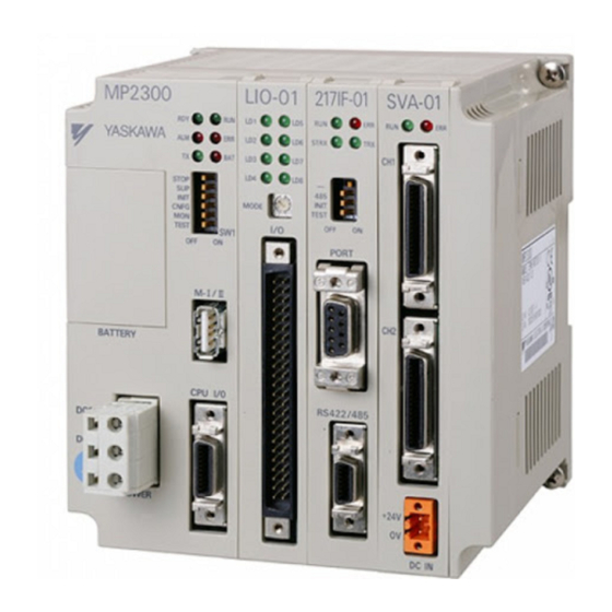
Machine Controller MP2000 Series
Ethernet Communication
Troubleshooting Manual
MP2300
RUN
ERR
RDY
RUN
STRX
COL
ALM
ERR
TX
RX
TX
BAT
STOP
SUP
INIT
INT
TEST
CNFG
OFF
ON
MON
SW1
TEST
PORT
OFF ON
M-4/10
BATTERY
CPU I/O
DC24V
10Base-T
DC 0V
MANUAL NO. SIEP C880700 45A
Troubleshooting Errors in Communication with MPE720
Troubleshooting Errors in Message Communication
Overview of Troubleshooting
1
2
3
Advertisement
Table of Contents
Troubleshooting

Subscribe to Our Youtube Channel
Related Manuals for YASKAWA MP2000 Series


Summary of Contents for YASKAWA MP2000 Series
- Page 1 Machine Controller MP2000 Series Ethernet Communication Troubleshooting Manual MP2300 STRX STOP INIT TEST CNFG TEST PORT OFF ON M-4/10 BATTERY CPU I/O DC24V 10Base-T DC 0V Overview of Troubleshooting Troubleshooting Errors in Communication with MPE720 Troubleshooting Errors in Message Communication MANUAL NO.
- Page 2 Yaskawa. No patent liability is assumed with respect to the use of the information contained herein. Moreover, because Yaskawa is con- stantly striving to improve its high-quality products, the information contained in this manual is subject to change without notice.
- Page 3 Read this manual carefully to ensure correct operation in Ethernet communication with MP2000 Series Machine Con- trollers. Using this Manual Read this manual carefully to ensure the proper use of the MP2000 Series Machine Controller. Also, keep this manual in a safe place so that it can be referred to whenever necessary. Visual Aids The following aids are used to indicate certain types of information for easier reference.
- Page 4 Machine Controller MP2000 Series MPU-01 procedures of the MPU-01 Motion CPU Module that SIEP C880781 05 Multiple-CPU Module User’s Manual can be connected to MP2000 Series Machine Con- trollers. Machine Controller MP2300 Basic Module Describes the application methods and modules to be SIEP C880700 03 User’s Manual...
- Page 5 Safety Information This manual presents safety information using the following notices. The safety information is important and must be observed. Indicates precautions that, if not heeded, could possibly result in loss of life, serious WARNING injury, or property damage. Indicates precautions that, if not heeded, could result in relatively serious or minor CAUTION injury, or property damage.
- Page 6 • Do not damage, pull on, apply excessive force to, place heavy objects on, or pinch cables. There is a risk of electrical shock, operational failure or burning of the MP2000 Series Machine Controller. • Do not attempt to modify the MP2000 Series Machine Controller in any way.
- Page 7 • Do not step on the MP2000 Series Machine Controller or place heavy objects on it. There is a risk of injury. • Do not block the air exhaust port or allow foreign objects to enter the MP2000 Series Machine Con- troller.
- Page 8 • Install breakers and other safety measure to provide protection against shorts in external wiring. There is a risk of fire. • Provide sufficient shielding when using the MP2000 Series Machine Controller in the following loca- tions. There is a risk of device damage.
- Page 9 • When replacing the MP2000 Series Machine Controller, restart operation only after transferring the programs and parameters from the old Module to the new Module. If the MP2000 Series Machine Controller is operated without having transferred the data, there is a risk of device damage.
- Page 10 6. Events for which Yaskawa is not responsible, such as natural or human-made disasters ( 2 ) Limitations of Liability 1. Yaskawa shall in no event be responsible for any damage or loss of opportunity to the customer that arises due to failure of the delivered product.
- Page 11 1. It is the customer’s responsibility to confirm conformity with any standards, codes, or regulations that apply if the Yaskawa product is used in combination with any other products. 2. The customer must confirm that the Yaskawa product is suitable for the systems, machines, and equipment used by the customer.
-
Page 12: Table Of Contents
Contents Preface - - - - - - - - - - - - - - - - - - - - - - - - - - - - - - - - - - - - - - - - - - - - - - - - - - - - - - - - - - - - - - - ii Using this Manual- - - - - - - - - - - - - - - - - - - - - - - - - - - - - - - - - - - - - - - - - - - - - - - - - - - - - - - - ii Safety Information - - - - - - - - - - - - - - - - - - - - - - - - - - - - - - - - - - - - - - - - - - - - - - - - - - - - - - iv Safety Precautions - - - - - - - - - - - - - - - - - - - - - - - - - - - - - - - - - - - - - - - - - - - - - - - - - - - - - - - v... -
Page 13: Overview Of Troubleshooting
Overview of Troubleshooting 1.1 Flow for Checking Trouble - - - - - - - - - - - - - - - - - - - - - - - - - - - - - - - - - - - - - - - 1-2 1.1.1 Overview - - - - - - - - - - - - - - - - - - - - - - - - - - - - - - - - - - - - - - - - - - - - - - - - - - - - - - - - - - - - 1-2 1.1.2 Details - - - - - - - - - - - - - - - - - - - - - - - - - - - - - - - - - - - - - - - - - - - - - - - - - - - - - - - - - - - - - - 1-3 1.2 Checking Ethernet Cables - - - - - - - - - - - - - - - - - - - - - - - - - - - - - - - - - - - - - - - 1-4... -
Page 14: Flow For Checking Trouble
1.1 Flow for Checking Trouble 1.1.1 Overview 1.1 Flow for Checking Trouble 1.1.1 Overview When trouble occurs in Ethernet communication, the important issue is to recover normal system operation as soon as possible by finding the cause of the trouble and taking the necessary measures. The overview of troubleshooting on occurrence of trouble is as follows. -
Page 15: Details
1.1 Flow for Checking Trouble 1.1.2 Details 1.1.2 Details Start A cross-over Use a cross-over cable. cable is used for the direct If the connection is made via connection between the computer a hub, use straight cables. and the Ethernet Module. -
Page 16: Checking Ethernet Cables
1.2 Checking Ethernet Cables 1.2 Checking Ethernet Cables The use of incorrect Ethernet cables may impede appropriate connection with MPE720 and message communication. For Ethernet cables, use the twisted-pair cables with RJ-45 connectors shown below. Module Model Ethernet Type Category Remarks •... -
Page 17: Checking The Led Indications
1.4 Checking the LED Indications 1.4.1 Built-in Ethernet Module 1.4 Checking the LED Indications The error status and the details of the error can be checked using the LED indications at the front of the Ethernet Module. This section describes the patterns of LED indications and their details. 1.4.1 Built-in Ethernet Module Note: Machine Controllers MP2300S, MP2400 and MP2310 incorporate a built-in Ethernet Module. -
Page 18: 218If-02 Module
1.4 Checking the LED Indications 1.4.2 218IF-02 Module 1.4.2 218IF-02 Module LEDs on the Ethernet connector LEDs at the front of the Ethernet Module Ethernet LINK STRX 100M LED Indication Cate- Module Front Connector Indication Remedy gory LINK Normal – –... -
Page 19: 218If-01 Module
1.4 Checking the LED Indications 1.4.3 218IF-01 Module 1.4.3 218IF-01 Module LEDs at the front of the Ethernet Module STRX LED Indication Cate- Module Front Indication Remedy gory Normal – – Operating normally Normal operation is in progress. Ethernet connection is not established. Check the following. -
Page 20: Troubleshooting Quick Reference
1.5 Troubleshooting Quick Reference 1.5 Troubleshooting Quick Reference This section provides examples of Ethernet communication trouble that occurs frequently and can be remedied with relatively simple operations. If the error cannot be corrected by following the information in the table below, troubleshoot it by referring to the flow in 1.1.2 Details. -
Page 21: Troubleshooting Errors In Communication With Mpe720
Troubleshooting Errors in Communication with MPE720 2.1 Flow for Checking Trouble - - - - - - - - - - - - - - - - - - - - - - - - - - - - - - - - - - - - - - - 2-2 2.2 Checking Error Details - - - - - - - - - - - - - - - - - - - - - - - - - - - - - - - - - - - - - - - - - 2-3 2.2.1 Connection Error - - - - - - - - - - - - - - - - - - - - - - - - - - - - - - - - - - - - - - - - - - - - - - - - - - - - - - - 2-3 2.2.2 Communication Error - - - - - - - - - - - - - - - - - - - - - - - - - - - - - - - - - - - - - - - - - - - - - - - - - - - - 2-3... -
Page 22: Flow For Checking Trouble
PLC folder or project appropriate value. appropriate for the target MP2000 Series Machine Controller (CPU). For details, refer to 2.3 Checking the IP Address of the Computer. Check whether the communication settings of MPE720 are appropriate. -
Page 23: Checking Error Details
2.2 Checking Error Details 2.2.1 Connection Error 2.2 Checking Error Details If a connection with MPE720 cannot be established, check the details of the error by referring to the information that MPE720 notifies. The error information notified is given below. 2.2.1 Connection Error If the message “Cannot connect to the controller.”... -
Page 24: Model Error
2.2 Checking Error Details 2.2.3 Model Error 2.2.3 Model Error If the message “It is not possible to connect, because the controller type is different.” is displayed, MPE720 may have been connected to the Ethernet Module by selecting a project* that does not match the model of the target Machine Controller (CPU). -
Page 25: Checking The Ip Address Of The Computer
2.3 Checking the IP Address of the Computer 2.3 Checking the IP Address of the Computer The procedure for checking the network settings of the computer (IP address, etc.) and the remedies are given below. Open the Local Area Connection Properties dialog box on the computer. a) For Windows 2000 Select Start - Settings - Control Panel - Network and Dial-up Connections - Local Area Connection - Prop- erties. - Page 26 2.3 Checking the IP Address of the Computer Check the actual status of the IP address and subnet mask. a) For Windows 2000 Select Start - Programs - Accessories - Command Prompt and enter “ipconfig” in the command line. b) For Windows XP Select Start - Control Panel - Network Connections - Local Area Connection and click the Support tab.
-
Page 27: Checking The Communication Settings
2.4 Checking the Communication Settings 2.4 Checking the Communication Settings The procedure for checking the communication settings of MPE720 version 6, and remedies, are given below. Open the IP address confirmation window of the computer. For details, refer to steps 1 and 2 in 2.3 Checking the IP Address of the Computer. Start MPE720 version 6 and click Communications Setting. - Page 28 2.4 Checking the Communication Settings Communication Port Kind Combination Table Built-in Ethernet Port Kind or 218IF-02 218IF-01 Module Remarks Module Ethernet Supported Supported This port kind can be selected for all Ethernet Modules. If this port kind is selected for the 218IF-01 Module, the Supported Not supported Ethernet (LP)
-
Page 29: Checking The Communication Process Settings
2.5 Checking the Communication Process Settings 2.5 Checking the Communication Process Settings The procedure for checking the communication process settings of MPE720, and remedies, are given below. Open the IP address confirmation window of the computer. For details, refer to steps 1 and 2 in 2.3 Checking the IP Address of the Computer. Start the communication process. - Page 30 2.5 Checking the Communication Process Settings Click the Logical PT field of the communication whose port kind is displayed to display the Logical Port Setting dialog box. Note: Port kind: Ethernet or Ethernet (LP) Note that CP-218 will be displayed instead of Ethernet in the Communication Manager window and the Logical Port Setting dialog box.
- Page 31 2.5 Checking the Communication Process Settings Save the communication process settings and exit the application program. If MPE720 has been started, exit MPE720 as well. Click this icon to save the communication process settings. Restart MPE720 to enable the settings. 2-11...
-
Page 32: Communication Time-Out Error
2.6 Communication Time-out Error 2.6 Communication Time-out Error The communication with MPE720 is processed with a lower priority than the high-speed scan processes. Because of this, the communication with MPE720 may time out if the high-speed scan time is set too small. Set a large enough value for the high-speed scan compared to the current and maximum values during the operation of the application. -
Page 33: Troubleshooting Errors In Message
Troubleshooting Errors in Message Communication 3.1 Flow for Checking Trouble - - - - - - - - - - - - - - - - - - - - - - - - - - - - - - - - - - - - - - - 3-2 3.2 Checking Switch Settings - - - - - - - - - - - - - - - - - - - - - - - - - - - - - - - - - - - - - - - 3-5 3.2.1 Built-in Ethernet Module - - - - - - - - - - - - - - - - - - - - - - - - - - - - - - - - - - - - - - - - - - - - - - - - - - 3-5 3.2.2 218IF-02 and 218IF-01 Modules - - - - - - - - - - - - - - - - - - - - - - - - - - - - - - - - - - - - - - - - - - - - 3-5... -
Page 34: Flow For Checking Trouble
3.1 Flow for Checking Trouble 3.1 Flow for Checking Trouble If message communication with the controller or touch panel of another manufacturer or the computer fails, take the necessary corrective action by referring to the flow shown below. Start Check the message Message communication function and Ethernet does not start. - Page 35 3.1 Flow for Checking Trouble From the previous page “---” (no display) is IDLE is displayed displayed in the Transmission in the Transmission Status field. Status field. Perform the following operations. Set the connection Create a message function. parameters on the Execute the message function.
- Page 36 3.1 Flow for Checking Trouble From the previous page The local WAIT is displayed station is the master in the Transmission station (the MSG-SND Status field. function is used). Check the following. Check the process The remote device exists and result of the message the power to the remote transmission function,...
-
Page 37: Checking Switch Settings
3.2 Checking Switch Settings 3.2.1 Built-in Ethernet Module 3.2 Checking Switch Settings If message communication with the controller or touch panel of another manufacturer does not start even though the connection with MPE720 can be established properly, check the following switch settings. 3.2.1 Built-in Ethernet Module Note: Machine Controllers MP2300S, MP2400 and MP2310 incorporate a built-in Ethernet Module. -
Page 38: Message Communication Error
3.3 Message Communication Error 3.3.1 Checking the Error Status and Transmission Status 3.3 Message Communication Error 3.3.1 Checking the Error Status and Transmission Status If message communication with the PLC or touch panel of another manufacturer or the computer does not start, check the overview of the error details in the Status tab page of the module detailed definition window of MPE720. - Page 39 3.3 Message Communication Error 3.3.1 Checking the Error Status and Transmission Status [ b ] When the UDP protocol is selected Trans Status Cause Remedy Refer to Status Field Connection parameters have not been 3.3.2 Set the connection parameters. set. After setting the connection parameters, Message After setting connection parameters,...
- Page 40 3.3 Message Communication Error 3.3.1 Checking the Error Status and Transmission Status ( 2 ) When other than 0: No error is Displayed in the Error Status Field Check the overview of the error details by referring to the Error Status field. The list of error statuses that frequently occur is given below.
-
Page 41: Checking The Connection Parameters
3.3 Message Communication Error 3.3.2 Checking the Connection Parameters 3.3.2 Checking the Connection Parameters If message communication with the PLC or touch panel of another manufacturer or the computer does not start, the connection parameter settings in the module detailed definition window may be faulty. Check the connection parameter settings according to the following procedure. - Page 42 3.3 Message Communication Error 3.3.2 Checking the Connection Parameters b) For a 218IF-02 Module c) For a 218IF-01 Module 3-10...
- Page 43 3.3 Message Communication Error 3.3.2 Checking the Connection Parameters Check the connection parameter settings. Connection Parameter Settings Note: For the 218IF-02 and 218IF-01 Modules, Detail Setting is not displayed. Connection Parameter Check Items Setting Item Check Item Remarks Set the transmission target port number to be used Local Port –...
- Page 44 3.3 Message Communication Error 3.3.2 Checking the Connection Parameters Click the Status tab to open the Status tab page, and check that the following settings are equivalent to those on the Parameter Setting tab page in the module detailed definition window. •...
-
Page 45: Checking The Message Function
3.3 Message Communication Error 3.3.3 Checking the Message Function 3.3.3 Checking the Message Function If message communication with the PLC or touch panel of another manufacturer or the computer does not start, the details of the error can be determined by checking the process result of the message function and the status. The procedures for checking the process result of the message function, status, and parameter settings are given below. - Page 46 3.3 Message Communication Error 3.3.3 Checking the Message Function [ a ] Checking the process result (PARAM00) when using the message transmission function (MSG- SND) • When the process result is other than the communication section error (88xxH) Value of Process Error Details Cause Remedy...
- Page 47 3.3 Message Communication Error 3.3.3 Checking the Message Function [ b ] Checking the process result (PARAM00) when using the message receive function (MSG-RCV) • When the process result is other than the communication section error (88xxH) Value of Process Error Details Cause Remedy...
- Page 48 3.3 Message Communication Error 3.3.3 Checking the Message Function [ c ] Checking the status (PARAM01) F E D C B A 4. PARAMETER Bits 0 to 7 3. COMMAND Bits 8 to B 2. RESULT Bits C to E 1.
- Page 49 3.3 Message Communication Error 3.3.3 Checking the Message Function 4. PARAMETER (parameter) When RESULT (process result) = 4 (FMT_NG: parameter format error), an error code in the table below is output. RESULT (process result) Code (Hex) Meaning No error Connection number is out of range Time error for monitoring to receive MEMOBUS response Error in setting retransmit count When RESULT (process result) = 4...
- Page 50 3.3 Message Communication Error 3.3.3 Checking the Message Function [ b ] Pro-Typ (Transmission protocol) Specifies the type code of the transmission protocol. (Refer to the table below.) Type Code Transmission Protocol Remarks • If the protocol type has been set to Extended MEMOBUS, MEMOBUS, MELSEC, or MODBUS/TCP in the Connection Parameter Setting tab page of the module detailed definition window, set 1 for the type code.
- Page 51 3.3 Message Communication Error 3.3.3 Checking the Message Function [ d ] Ch-No (Communication Buffer Channel) Specifies the channel number of the communication buffer. The communication buffer channel number is the buffer number to be used for the data exchange between the CPU Module and the Ethernet Module.
- Page 52 3.3 Message Communication Error 3.3.3 Checking the Message Function ( 3 ) Checking the Message Function Parameters If message communication with the PLC or touch panel of another manufacturer or the computer does not start, the message function may not have been executed properly due to incorrect setting of the message function parameters. Check the settings of the message function parameters by following the procedure below.
- Page 53 3.3 Message Communication Error 3.3.3 Checking the Message Function [ a ] When using the message transmission function (MSG-SND) • Parameter list when Pro-Typ (Transmission protocol) is MEMOBUS Parameter Setting Item Description and Checking Details IN/OUT Sets the transmission target to be used at the remote station. (Specify the connection number in the connection parameters.) Check that the setting is within the following setting range.
- Page 54 3.3 Message Communication Error 3.3.3 Checking the Message Function [ b ] When using the message receive function (MSG-RCV) • Parameter list when Pro-Typ (Transmission protocol) is MEMOBUS Parameter Details Description and Checking Details IN/OUT Sets the transmission source to be used at the remote station. (Specify the connection number in the connection parameters.) Check that the setting is within the following setting range.
-
Page 55: Communication Broken Off During Message Communication
3.4 Communication Broken off during Message Communication 3.4.1 When No Error Is in Effect 3.4 Communication Broken off during Message Communication 3.4.1 When No Error Is in Effect The table below shows the possible causes for a message communication break during the process of normal communi- cation with no error indicated in the error status of the module detailed definition or in the process result of the message function. -
Page 56: When An Error Is In Effect
3.4 Communication Broken off during Message Communication 3.4.2 When an Error Is in Effect 3.4.2 When an Error Is in Effect The table below shows the possible causes for a message communication break during the process of normal communi- cation with an error indicated in the error status of the module detailed definition or in the process result of the message function, in addition to the causes listed in 3.4.1 When No Error Is in Effect. -
Page 57: Other Trouble During Message Communication
3.5 Other Trouble during Message Communication 3.5 Other Trouble during Message Communication If the trouble cannot be resolved with the remedies given in 3.2 Checking Switch Settings to 3.4 Communication Bro- ken off during Message Communication, perform troubleshooting using the remedies given in the table below. Module Model Error Details Cause... -
Page 58: Index
Index Index Numerics 218IF-01 module - - - - - - - - - - - - - - - - - - - - - - - - - - - 1-4 218IF-02 module - - - - - - - - - - - - - - - - - - - - - - - - - - - 1-4 auto-negotiation - - - - - - - - - - - - - - - - - - - - - - - - - - - - - - - - - - - 1-4 built-in Ethernet module - - - - - - - - - - - - - - - - - - - - - - 1-4 checking... -
Page 59: Revision History
Revision History The revision dates and numbers of the revised manuals are given on the bottom of the back cover. MANUAL NO. SIEP C880700 45A Published in Japan October 2010 10-10 Date of Date of original publication publication Date of Publication Rev. - Page 60 Phone 81-4-2962-5151 Fax 81-4-2962-6138 YASKAWA AMERICA, INC. 2121 Norman Drive South, Waukegan, IL 60085, U.S.A. Phone (800) YASKAWA (800-927-5292) or 1-847-887-7000 Fax 1-847-887-7310 YASKAWA ELETRICO DO BRASIL LTDA. Avenida Fagundes Filho, 620 Sao Paulo-SP CEP 04304-000, Brazil Phone 55-11-3585-1100 Fax 55-11-5581-8795 YASKAWA EUROPE GmbH Hauptstraβe 185, Eschborn 65760, Germany...
Need help?
Do you have a question about the MP2000 Series and is the answer not in the manual?
Questions and answers