
Keysight N1911A Manuals
Manuals and User Guides for Keysight N1911A. We have 4 Keysight N1911A manuals available for free PDF download: Programming Manual, User Manual, Installation Manual, Configuration Manual
Keysight N1911A Programming Manual (771 pages)
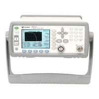
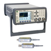
P-Series Power Meters
Brand: Keysight
|
Category: Measuring Instruments
|
Size: 10 MB
Table of Contents
-
-
Introduction28
-
Range60
-
Using Status66
-
-
Trigger Mode68
-
Command Used70
-
Fast Mode71
-
-
-
-
-
-
-
Digital Display243
-
-
-
Memory Subsystem268
-
Memory:nstates284
-
-
-
-
Sense Subsystem363
-
-
-
Status Subsystem466
-
Status:operation476
-
Status:preset483
-
-
-
System Subsystem493
-
System:error514
-
System:local523
-
System:remote608
-
System:rwlock609
-
System:version610
-
-
Trace Subsystem612
-
-
-
Abort[1]|2]642
-
Trigger Commands653
-
-
Unit Subsystem728
Advertisement

Keysight N1911A User Manual (287 pages)
P-Series Power Meters
Brand: Keysight
|
Category: Measuring Instruments
|
Size: 6 MB
Table of Contents
-
-
-
-
Procedure60
-
-
-
-
Procedure81
-
-
-
-
Procedure92
-
Auto Scale95
-
-
-
Procedure97
-
Power Sweep Mode104
-
Recorder Output131
-
-
-
Introduction150
-
-
-
-
Introduction166
-
-
Procedure170
-
-
-
-
-
Introduction186
-
-
Procedure190
-
-
-
-
Introduction208
-
-
Procedure218
-
Figure 5-2226
-
-
-
-
Introduction230
-
-
Procedure235
-
-
-
-
-
Introduction252
-

Keysight N1911A Installation Manual (57 pages)
P-Series Power Meter
Brand: Keysight
|
Category: Measuring Instruments
|
Size: 4 MB
Table of Contents
Advertisement
Keysight N1911A Configuration Manual (6 pages)
P Series Power Meters and P Series Wideband Power Sensors
Brand: Keysight
|
Category: Measuring Instruments
|
Size: 0 MB