Table of Contents
Advertisement
Quick Links
Machine Controller MP3000 Series
Motion Control
USER'S MANUAL
SVC/SVR, SVC32/SVR32
MANUAL NO. SIEP C880725 11E
Basic Information on
Motion Control
Basic Information on Motion
Control Function Modules
Parameters for Motion Control
Motion Control Program
Commands and Instructions
Machine-Specific
Motion Control
Other Useful Functions
Making Settings for Motion
Control with the MPE720
Sample Programming
Stepping Motor Drive Operation
Inverter Operation
Appendices
1
2
3
4
5
6
7
8
9
10
11
Advertisement
Table of Contents

Related Manuals for YASKAWA SVC


Summary of Contents for YASKAWA SVC
- Page 1 Machine Controller MP3000 Series Motion Control USER’S MANUAL SVC/SVR, SVC32/SVR32 Basic Information on Motion Control Basic Information on Motion Control Function Modules Parameters for Motion Control Motion Control Program Commands and Instructions Machine-Specific Motion Control Other Useful Functions Making Settings for Motion...
- Page 2 Yaskawa. No patent liability is assumed with respect to the use of the informa- tion contained herein. Moreover, because Yaskawa is constantly striving to improve its high-quality products, the information contained in this manual is sub- ject to change without notice.
- Page 3 About this Manual This manual describes the specifications, system configurations, and operating methods for the SVC, SVR, SVC32, and SVR32 Function Modules that are used in an MP3000-series Machine Controller for motion control. Read this manual carefully to ensure the correct usage of the Machine Controller and apply the Machine Controller to control your manufacturing system.
- Page 4 Describes the functions, specifica- Machine Controller MP2000 Series tions, and operating methods of the SIEP C880700 41 SVC-01 Motion Module User’s Manual MP2000-series SVC-01 Motion Mod- ule. Machine Controller MP2000 Series Describes the functions, specifica- Pulse Output Motion Module PO-01...
- Page 5 Continued from previous page. Category Manual Name Manual Number Contents Describes the functions, specifica- tions, operating methods, and MECHA- MECHATROLINK-III Compatible I/O SIEP C880781 04 TROLINK-III communications for the Module User’s Manual MECHA- Remote I/O Modules for MP2000/ TROLINK MP3000-series Machine Controllers. Machine Controller MP900/MP2000 Describes MECHATROLINK distrib- Series Distributed I/O Module...
- Page 6 Interface Unit. • MP3300: A generic name for the CPU Module and Base Unit. • SVC Function Module: A generic name for the SVC and SVC32. • SVR Function Module: A generic name for the SVR and SVR32. Engineering Tools Used in This Manual In this manual, the operation is described using MPE720 screen captures.
- Page 7 Safety Precautions Safety Information To prevent personal injury and equipment damage in advance, the following signal words are used to indicate safety precautions in this document. The signal words are used to classify the hazards and the degree of damage or injury that may occur if a product is used incorrectly. Information marked as shown below is important for safety.
- Page 8 Safety Precautions That Must Always Be Observed General Precautions DANGER Read and understand this manual to ensure the safe usage of the SERVOPACK. Keep this manual in a safe, convenient place so that it can be referred to whenever necessary. Make sure that it is delivered to the final user of the SERVOPACK.
- Page 9 NOTICE Do not attempt to use a SERVOPACK or Servomotor that is damaged or that has missing parts. Install external emergency stop circuits that shut OFF the power supply and stop operation immediately when an error occurs. In locations with poor power supply conditions, install the necessary protective devices (such as AC reactors) to ensure that the input power is supplied within the specified voltage range.
- Page 10 NOTICE Do not hold onto the front cover or connectors when you move a SERVOPACK. There is a risk of the SERVOPACK falling. The SERVOPACK or Servomotor is a precision device. Do not drop it or subject it to strong shock.
- Page 11 NOTICE Do not install or store the SERVOPACK in any of the following locations. • Locations that are subject to direct sunlight • Locations that are subject to ambient temperatures that exceed SERVOPACK specifications • Locations that are subject to relative humidities that exceed SERVOPACK specifications •...
- Page 12 CAUTION Wait for at least six minutes after turning OFF the power supply and then make sure that the CHARGE indicator is not lit before starting wiring or inspection work. Do not touch the power supply terminals while the CHARGE lamp is lit because high voltage may still remain in the SER- VOPACK even after turning OFF the power supply.
- Page 13 Whenever possible, use the Cables specified by Yaskawa. If you use any other cables, confirm the rated current and application environment of your model and use the wiring materials specified by Yaskawa or equivalent materials. Securely tighten cable connector lock screws and lock mechanisms.
- Page 14 Operation Precautions WARNING Before starting operation with a machine connected, change the settings of the switches and parameters to match the machine. Unexpected machine operation, failure, or personal injury may occur if operation is started before appropriate settings are made. ...
- Page 15 CAUTION Design the system to ensure safety even when problems, such as signal line disconnection, occur. For example, the P-OT and N-OT signals are set in the default settings to operate on the safe side if there is a signal line disconnection. Do not change the polarity of this type of signal. ...
- Page 16 CAUTION Always check to confirm the paths of axes when any of the following axis movement instruc- tions are used in programs to ensure that the system operates safely. • Positioning (MOV) • Linear Interpolation (MVS) • Circular Interpolation (MCC or MCW) •...
- Page 17 CAUTION The Move on Machine Coordinates (MVM) instruction temporarily performs positioning to a coordinate position in the machine coordinate system. Therefore, unexpected operation may occur if the instruction is executed without confirming the origin position in the machine coordi- nate system first.
- Page 18 NOTICE Discharge all static electricity from your body before you operate any of the buttons or switches inside the front cover of the SERVOPACK. There is a risk of equipment damage. Troubleshooting Precautions DANGER If the safety device (molded-case circuit breaker or fuse) installed in the power supply line oper- ates, remove the cause before you supply power to the SERVOPACK again.
- Page 19 We will update the document number of the manual and issue revisions when changes are made. Any and all quality guarantees provided by Yaskawa are null and void if the customer modifies the SERVOPACK in any way. Yaskawa disavows any responsibility for damages or losses that...
- Page 20 • Events for which Yaskawa is not responsible, such as natural or human-made disasters Limitations of Liability • Yaskawa shall in no event be responsible for any damage or loss of opportunity to the customer that arises due to failure of the delivered product.
- Page 21 • It is the customer’s responsibility to confirm conformity with any standards, codes, or regulations that apply if the Yaskawa product is used in combination with any other products. • The customer must confirm that the Yaskawa product is suitable for the systems, machines, and equipment used by the customer.
-
Page 22: Table Of Contents
SVC Function Module ........2-7... - Page 23 Parameters for Motion Control Types of Motion Parameters ......3-2 Motion Parameter Registers ......3-3 Motion Parameter Tables .
-
Page 24: Machine-Specific
4.2.24 PHASE (Issue Phase Reference) ....... . .4-99 4.2.25 KIS (Change Position Loop Integral Time Constant) ....4-103 4.2.26 PPRM_WR (Write Non-volatile Parameter) . - Page 25 Related Parameters ......... . 6-10 6.3.3 Comparison with the MP2000-series SVC-01 Module ....6-10 6.3.4 The Effects of Software Limits .
-
Page 26: Making Settings For Motion
Precautions When Using Σ-7-series SERVOPACKs ..6-34 MP3000 Versions That Support the Σ-7-series SERVOPACKs ..6-34 6.8.1 Σ-7-series SERVOPACK Electronic Gear Ratio and MP3000 Settings..6-35 6.8.2 6.8.3 Link Assignments . -
Page 27: Stepping Motor Drive Operation
Stepping Motor Drive Operation Overview ......... . . 9-2 Connection Specifications . - Page 28 11.2 System Registers ........11-10 11.2.1 System Service Registers ........11-10 11.2.2 Scan Execution Status and Calendar .
-
Page 29: Basic Information On Motion Control
Basic Information on Motion Control This chapter describes the types of programs and the types of motion control that are used to perform motion control with the MP3000. Types of Programs ....1-2 Types of Motion Control . -
Page 30: Types Of Programs
1.1 Types of Programs Types of Programs Ladder programs and motion programs are used to implement motion control. This section describes each type of program. Ladder Programs Ladder programming is a programming language for executing position control, phase control, torque control, and speed control. However, programming becomes complex if you try to use ladder programs for path control. -
Page 31: Types Of Motion Control
1.2 Types of Motion Control 1.2.1 Position Control Types of Motion Control Motion control includes position control, phase control, torque control, and speed control. This section describes each type of motion control. 1.2.1 Position Control To implement position control, the target axis is moved to the target position according to the specified travel distance and travel speed. -
Page 32: Phase Control
1.2 Types of Motion Control 1.2.2 Phase Control 1.2.2 Phase Control Phase control is used to synchronize multiple axes and move a machine along a specified path. It enables continuous motion without stopping at target positions, in the same way as an elec- tronic cam or electronic shaft. -
Page 33: Basic Information On Motion Control Function Modules
Overview ......2-3 2.1.1 SVC Function Module ..... 2-3 2.1.2 SVR Function Module . - Page 34 2.6.4 Reference Output Timing ....2-20 2.6.5 Precautions When Combining with Other Modules ..... .2-21...
-
Page 35: Overview
MP3000. 2.1.1 SVC Function Module The SVC Function Module performs motion control for MECHATROLINK-III slave devices that are connected through MECHATROLINK-III communications from the MP3000. The main slave devices are SERVOPACKs, Distributed I/O Modules, Inverters, and Stepping Motor Drives. -
Page 36: Conceptual Diagram
Module Due to the following differences between the SVR Function Module and Simulation Mode with the SVC Function Module, we recommend that you use the SVR Function Module for the virtual mas- Term ter to create master axis operating patterns. -
Page 37: External Appearance And Indicators
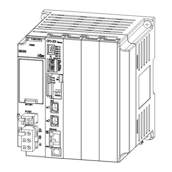
2.1 Overview 2.1.4 External Appearance and Indicators 2.1.4 External Appearance and Indicators External Appearance The following figure shows the indicators and connectors that are related to the SVC32. Indicators (LEDs) MECHATROLINK-III connector CN1 MECHATROLINK-III connector CN2 Indicators The following table describes the indicators that show the operating status of the SVC32 and error information. -
Page 38: Specifications
2.2.1 Motion Control Function Module Specifications Specifications This section provides the specifications of each Motion Control Function Module and the spec- ifications of the MECHATROLINK-III communications used with the SVC Function Module. 2.2.1 Motion Control Function Module Specifications The following table gives the specifications of the Motion Control Function Modules. -
Page 39: Mechatrolink-Iii Communications Specifications For The Svc Function Module
MECHATROLINK-III servo standard profile, MECHATROLINK-III I/O standard Supported Profiles profile, MECHATROLINK-III inverter standard profile, and MECHATROLINK-III stepping motor standard profile The transmission cycle is used to perform communications between the SVC Function Module and the slave devices through the MECHATROLINK-III transmission line. -
Page 40: Svc Function Module Specifications
Number of Link Communications 16, 32, 48, or 64 (depending on the profile) Bytes SVC32: 42 max. (32 Servo axes max.) Number of Connected Stations SVC: 21 max. (16 Servo axes max.) C1 Messaging Supported (selectable). (Master Function) Retry Function Supported (selectable). - Page 41 2.2 Specifications 2.2.3 SVC Function Module Specifications Continued from previous page. Item Specification Synchronous communications through single send transmis- sions Transmission/communications error detection (hardware) pro- vided. Communication Methods Synchronous communications error detection (software) pro- vided. No automatic recovery function (recovery occurs when alarms are cleared).
-
Page 42: Svr Function Module Specifications
2.2 Specifications 2.2.4 SVR Function Module Specifications 2.2.4 SVR Function Module Specifications Item Specification I/O using motion registers (synchronized with the high-speed I/O Registers scan) Command Modes Motion command mode Supported Servomotors Standard and linear Servomotors Position control, speed control, torque control, and phase con- Control Types trol can be selected during operation. -
Page 43: Applicable Versions For Additional Functions
2.2 Specifications 2.2.5 Applicable Versions for Additional Functions 2.2.5 Applicable Versions for Additional Functions The following tables list the MP3000 and Engineering Tool versions that support the additional functions. Engineering MP3000 Tool MPE720 CPU-201 CPU-202 CPU-301 CPU-302 Version 7 Function JAPMC- JAPMC- JEPMC-... -
Page 44: System Configuration Example
2.3 System Configuration Example System Configuration Example The following figure shows a system configuration example that uses the Motion Control Func- tion Module. Configuration with the MP3200 The following figure shows a system configuration example that uses the SVC32. MPE720 Integrated Engineering Tool Version 7 Host PLC... - Page 45 ON the power supply to the MECHATROLINK slave devices. Otherwise, MECHATROLINK communications may not be performed correctly. Important Using the MP3300 The following figure shows a system configuration example that uses the SVC. MPE720 Integrated Engineering Tool Version 7...
-
Page 46: Topologies
2.4 Topologies 2.4.1 Cascade Connections Topologies The SVC Function Module uses MECHATROLINK-III communications to control slave devices. You can connect the MP3000 and MECHATROLINK-III slave devices with cascade, star, or mixed cascade/star topologies. This section describes these topologies. 2.4.1 Cascade Connections Cascade connections allow you to connect one or more series of slave stations from the MECHATROLINK-III communications port (CN6) on the MP3000. -
Page 47: Star Connections
2.4 Topologies 2.4.2 Star Connections 1. Do not connect more than 19 stations up to the final slave stations to any one CPU Unit port. 2. The maximum number of stations that you can connect with cascade connections depends on the transmission cycle. Refer to the following section for details. Important MECHATROLINK Transmission Cycle and the Number of Connected Slave Stations (page 2-17) 2.4.2... -
Page 48: Mixed Cascade/Star Connections
2.4 Topologies 2.4.3 Mixed Cascade/Star Connections 2.4.3 Mixed Cascade/Star Connections A mixed cascade/star topology combines both cascade and star connections. CPU Unit Hub Module No terminating resistor is required. No terminating resistor is required. 1. Do not connect more than 19 stations up to the final slave stations to any one CPU Unit port, including the Hub Modules. -
Page 49: Mechatrolink Transmission Cycle And The Number Of Connected Slave Stations
MECHATROLINK Transmission Cycle and the Number of Connected Slave Stations The relationship between the MECHATROLINK transmission cycle and the number of con- nected slave stations when the SVC Function Module is used is given in the following tables. Cascade Connections... - Page 50 2.5 MECHATROLINK Transmission Cycle and the Number of Connected Slave Stations 2.4.3 Mixed Cascade/Star Connections Mixed Cascade/Star Connections Number of Connected Stations Transmission Connection Conditions Cycle SVC32 125 μs 1 to 4 1 to 4 Only star connections can be used. A single cascade connection series must con- 250 μs 1 to 8...
-
Page 51: Synchronization Of The Mechatrolink-Iii Transmission Cycle And High-Speed Scan Cycle
2.6.1 Synchronization Conditions Synchronization of the MECHATROLINK-III Transmission Cycle and High-Speed Scan Cycle To perform motion control with the SVC Function Module, the MECHATROLINK transmission cycle and the high-speed scan cycle of the CPU must be synchronized. This section describes synchronization of the MECHATROLINK transmission cycle and the high-speed scan cycle. -
Page 52: Reference Output Timing
When the high-speed scan cycle is changed, MECHATROLINK communications with all slave stations connected to the SVC Function Module are reset. If the high-speed scan setting is an integral multiple or integral fraction of the MECHATROLINK transmission cycle, operation is automatically synchronized when communications are restored. -
Page 53: Precautions When Combining With Other Modules
MECHATROLINK will not coincide even though the same transmission cycle settings are used. The SVC Function Module minimizes the delay between the time a reference is set and a response is received. Therefore, the timing at which references are transmitted to the slave sta- tions will not coincide even between the SVC Function Module and SVC-01 Module. -
Page 54: Parameters For Motion Control
Parameters for Motion Control This chapter describes motion parameters required for motion control. Types of Motion Parameters ... . 3-2 Motion Parameter Registers ... . 3-3 Motion Parameter Tables . -
Page 55: Types Of Motion Parameters
3.1 Types of Motion Parameters Types of Motion Parameters Motion parameters are necessary to perform motion control. Motion parameters include fixed parameters, setting parameters, and monitor parameters. Descriptions of the various types of motion parameters are given in the following table. Parameters Overview Fixed Parameters... -
Page 56: Motion Parameter Registers
Motion Control Function Module and the axis number that is assigned. This section describes the default settings of the motion parameter registers that are allocated to the SVC and SVR Function Modules, and the motion parameter registers that can be used. - Page 57 3.2 Motion Parameter Registers Axis Numbers 9 to 16 Axis Axis Axis Axis Axis Axis Axis Circuit Axis Number Number Number Number Number Number Number Number Number 9 8400 to 8480 to 8500 to 8580 to 8600 to 8680 to 8700 to 8780 to 847F...
- Page 58 3.2 Motion Parameter Registers Axis Numbers 25 to 32 Axis Axis Axis Axis Axis Axis Axis Axis Circuit Number Number Number Number Number Number Number Number Number 8C00 to 8C80 to 8D00 to 8D80 to 8E00 to 8E80 to 8F00 to 8F80 to 8C7F...
- Page 59 3.2 Motion Parameter Registers Axis Numbers 9 to 16 Axis Axis Axis Axis Axis Axis Axis Axis Circuit Number Number Number Number Number Number Number Number Number 8400 to 8480 to 8500 to 8580 to 8600 to 8680 to 8700 to 8780 to 847F...
-
Page 60: Motion Parameter Tables
3.3 Motion Parameter Tables 3.3.1 Fixed Parameter Table Motion Parameter Tables This section provides tables of the motion parameters. 3.3.1 Fixed Parameter Table Fixed parameters are used to make settings related to the servo system. The following table lists the fixed parameters. Reference Name Description... - Page 61 3.3 Motion Parameter Tables 3.3.1 Fixed Parameter Table Continued from previous page. Reference Name Description Function Function Page Module Module Bit 0: Mask Communications Error Detection − (Communication abnormality detection mask) 0: Disabled, 1: Enabled Bit 1: Mask Watchdog Error Detection −...
- Page 62 3.3 Motion Parameter Tables 3.3.1 Fixed Parameter Table Continued from previous page. Reference Name Description Function Function Page Module Module Number of Pulses Per Motor Rotation 1 = 1 pulse/rev page 3-34 (Rotary Motor) Number of Pulses Per ...
-
Page 63: Setting Parameter Table
3.3 Motion Parameter Tables 3.3.2 Setting Parameter Table 3.3.2 Setting Parameter Table These parameters are used to set detailed aspects of control references used in motion con- trol. The following table lists the setting parameters. The boxes () in “OW00” are determined by the circuit number and the axis num- Information ber. - Page 64 3.3 Motion Parameter Tables 3.3.2 Setting Parameter Table Continued from previous page. Register Reference Name Description Function Function Address Page Module Module Bit 0: Excessive Deviation Error Level Setting – 0: Alarm, 1: Warning Bits 1 and 2: Reserved. –...
- Page 65 3.3 Motion Parameter Tables 3.3.2 Setting Parameter Table Continued from previous page. Register Reference Name Description Function Function Address Page Module Module Bit 0: Reserved. – – Bit 1: Disable Phase Reference Calcu- lation – 0: Enabled, 1: Disabled Bit 2: External Positioning Final Travel Distance Write Selection Function Set-...
- Page 66 3.3 Motion Parameter Tables 3.3.2 Setting Parameter Table Continued from previous page. Register Reference Name Description Function Function Address Page Module Module 0: NOP (No Operation) (No command) 1: POSING (Positioning) 2: EX_POSING (External Positioning) ...
- Page 67 3.3 Motion Parameter Tables 3.3.2 Setting Parameter Table Continued from previous page. Register Reference Name Description Function Function Address Page Module Module Bit 0: Hold Command (Holds a com- mand) 0: OFF, 1: ON Bit 1: Cancel Command (Interrupt a ...
- Page 68 3.3 Motion Parameter Tables 3.3.2 Setting Parameter Table Continued from previous page. Register Reference Name Description Function Function Address Page Module Module Speed Refer- The unit is set in bits 0 to 3 (Speed page 3-47 ence Setting Unit Selection) of OW03.
- Page 69 3.3 Motion Parameter Tables 3.3.2 Setting Parameter Table Continued from previous page. Register Reference Name Description Function Function Address Page Module Module Linear Deceler- The unit is set in bits 4 to 7 (Accelera- ation Rate/ tion/Deceleration Rate Unit Selection) page 3-56 Deceleration of OW03.
- Page 70 3.3 Motion Parameter Tables 3.3.2 Setting Parameter Table Continued from previous page. Register Reference Name Description Function Function Address Page Module Module SERVOPACK Sets the number of the alarm to moni- Alarm Monitor – page 3-63 tor. Number SERVOPACK Sets the SERVOPACK parameter num- ...
-
Page 71: Monitor Parameter Table
3.3 Motion Parameter Tables 3.3.3 Monitor Parameter Table Continued from previous page. Register Reference Name Description Function Function Address Page Module Module Power OFF Pulse Position (Pulse position 1 = 1 pulse – when power is off) (Lower 2 Words) page 3-66 Power OFF... - Page 72 3.3 Motion Parameter Tables 3.3.3 Monitor Parameter Table Register Reference Name Description Function Function Address Page Module Module Bit 0: Motion Operation Ready 0: Motion operation not ready 1: Motion operation ready Bit 1: Running with Servo ON (Running ...
- Page 73 3.3 Motion Parameter Tables 3.3.3 Monitor Parameter Table Continued from previous page. Register Reference Name Description Function Function Address Page Module Module Bit 0: SERVOPACK Error 0: No SERVOPACK alarm – 1: SERVOPACK alarm occurred Bit 1: Positive Overtravel (Positive direction overtravel) ...
- Page 74 3.3 Motion Parameter Tables 3.3.3 Monitor Parameter Table Continued from previous page. Register Reference Name Description Function Function Address Page Module Module Bit 10: SERVOPACK Synchronized Communications Error (Servo Driver Synch. Comm. error) 0: No synchronized communications – error 1: Synchronized communications error occurred Bit 11: SERVOPACK Communications...
- Page 75 3.3 Motion Parameter Tables 3.3.3 Monitor Parameter Table Continued from previous page. Register Reference Name Description Function Function Address Page Module Module Bit 0: Command Execution Flag (BUSY) 0: READY (Completed) 1: BUSY (Processing) Bit 1: Command Hold Completed (HOLDL) ...
- Page 76 3.3 Motion Parameter Tables 3.3.3 Monitor Parameter Table Continued from previous page. Register Reference Name Description Function Function Address Page Module Module Bit 0: Distribution Completed (DEN) (Discharging completed) 0: Distributing pulses 1: Distribution completed Bit 1: Positioning Completed (POS- COMP) ...
- Page 77 3.3 Motion Parameter Tables 3.3.3 Monitor Parameter Table Continued from previous page. Register Reference Name Description Function Function Address Page Module Module Machine Coor- dinate System 1 = 1 reference unit page 3-78 Feedback Posi- tion (APOS) Machine Coor- dinate System ...
- Page 78 3.3 Motion Parameter Tables 3.3.3 Monitor Parameter Table Continued from previous page. Register Reference Name Description Function Function Address Page Module Module Auxiliary SER- VOPACK Reports the number of the target – page 3-82 Parameter parameter. Number SERVOPACK The data of the SERVOPACK parameter ...
- Page 79 3.3 Motion Parameter Tables 3.3.3 Monitor Parameter Table Continued from previous page. Register Reference Name Description Function Function Address Page Module Module Power OFF Pulse Position (Pulse position 1 = 1 pulse – when power is off) (Lower 2 Words) page 3-84 Power OFF...
-
Page 80: Motion Parameter Details
These boxes show whether the parameter can be used with the SVC and SVR Function Modules. 3.4.1 Fixed Parameter Details This section provides details on each of the fixed parameters. Refer to the following section for a list of the fixed parameters. - Page 81 3.4 Motion Parameter Details 3.4.1 Fixed Parameter Details 3: SERVOPACK Transmission Reference Mode SERVOPACK Transmission Reference Mode is used to directly control the command-response communications with the slave SERVOPACK from an application. Setting Precautions • No processing other than communications processing with the SERVOPACK is performed in this mode.
- Page 82 3.4 Motion Parameter Details 3.4.1 Fixed Parameter Details Refer to the following section for details on the software limits. 6.3 Software Limits on page 6-9 Bit 3: Enable Positive Overtravel Enable or disable overtravel detection in the positive direction. 0: Disabled (default).
- Page 83 3.4 Motion Parameter Details 3.4.1 Fixed Parameter Details Bit C: Software Limit Parameter Selection Select whether the software limit is set in a fixed parameter or in a setting parameter. 0: Fixed parameter (default). 1: Setting parameter. Refer to the following section for details on the software limits. 6.3 Software Limits on page 6-9 ...
- Page 84 3.4 Motion Parameter Details 3.4.1 Fixed Parameter Details Reference Unit Selection Reference Unit Selection Set the reference unit. The reference unit is determined by this parameter and fixed parameter No. 5 (Number of Digits Below Decimal Point). Refer to the following section for details on reference units. 5.1.1 Reference Unit on page 5-3 Name Setting Range...
- Page 85 3.4 Motion Parameter Details 3.4.1 Fixed Parameter Details Servomotor Gear Ratio Term and Machine Gear Ratio Term Set the gear ratio between the motor and the load. The following two values are set for a machine configuration in which the load axis turns n times in response to m turns of the motor axis.
- Page 86 3.4 Motion Parameter Details 3.4.1 Fixed Parameter Details Negative Software Limit Set the position to detect the software limit in the reverse direction for the MP3000. Name Setting Range Setting Unit Default −1 Negative Software Limit Reference units to 2 Setting Precautions •...
- Page 87 3.4 Motion Parameter Details 3.4.1 Fixed Parameter Details Encoder Settings Rated Motor Speed (Rotary Motor) Set the rated motor speed in revolutions per minute. Name Setting Range Setting Unit Default Rated Motor Speed (Rotary 1 to 100,000 3,000 Motor) Setting Precautions Set this parameter based on the specifications of the motor.
- Page 88 3.4 Motion Parameter Details 3.4.1 Fixed Parameter Details Maximum Number of Absolute Encoder Rotations Set the maximum number of rotations that the absolute encoder can manage. This parameter is used to manage position information when an absolute encoder is used for an infinite-length axis.
-
Page 89: Setting Parameter Details
3.4 Motion Parameter Details 3.4.2 Setting Parameter Details 3.4.2 Setting Parameter Details This section provides details on each of the setting parameters. • Refer to the following section for a list of the setting parameters. Information 3.3.2 Setting Parameter Table on page 3-10 •... - Page 90 3.4 Motion Parameter Details 3.4.2 Setting Parameter Details Bit 6: Number of POSMAX Turns Preset Request Set this bit to 1 to preset the IL1E monitor parameter (Number of POSMAX Turns) to the value set for the OL4C setting parameter (Number of POSMAX Turns Preset Data). 0: Number of POSMAX turns preset request OFF (default).
- Page 91 3.4 Motion Parameter Details 3.4.2 Setting Parameter Details Bit B: Reset Integration Set this bit to 1 to reset the integration term in the position loop in the slave SERVOPACK. This setting is enabled when a travel motion command or a command to turn ON the Servomo- tor’s power is executed.
- Page 92 3.4 Motion Parameter Details 3.4.2 Setting Parameter Details Bit F: Clear Alarm Set this bit to 1 to clear an alarm. If a communications error occurs, communications can be reestablished by clearing the alarm. 0: Clear Alarm OFF (default). 1: Clear Alarm ON.
- Page 93 3.4 Motion Parameter Details 3.4.2 Setting Parameter Details Mode Settings 2 Mode Settings 2 Register Setting Name Setting Unit Default Control mode Address Range Phase Position − − OW02 0000 hex Mode Settings 2 Speed Torque Bits 8 to F: Stop Mode Selection Set the stop method for an axis that is in motion for a travel motion command.
- Page 94 3.4 Motion Parameter Details 3.4.2 Setting Parameter Details Bits C to F: Torque Unit Selection Set the unit for torque references. 0: Percentage of rated torque (1 = 0.01%). 1: Percentage of rated torque (1 = 0.0001%). Function Settings 2 ...
- Page 95 3.4 Motion Parameter Details 3.4.2 Setting Parameter Details Bit 2: External Positioning Final Travel Distance Write Selection This bit specifies whether or not to automatically apply the external positioning final travel dis- tance to the SERVOPACK during external positioning. This setting is applied at the start of exe- cution of the EX_POSING (External Positioning) and EX_FEED (Jog with External Positioning) motion commands.
- Page 96 3.4 Motion Parameter Details 3.4.2 Setting Parameter Details Motion Commands Motion Commands Set the motion command. Register Setting Name Setting Unit Default Control mode Address Range Phase Position − OW08 Motion Commands 0 to 39 Speed Torque 0: NOP (No Operation) 1: POSING (Positioning) 2: EX_POSING (External Positioning) 3: ZRET (Zero Point Return)
- Page 97 3.4 Motion Parameter Details 3.4.2 Setting Parameter Details Motion Command Control Flags Motion Command Control Flags Register Setting Name Setting Unit Default Control mode Address Range Phase Position Motion Command Control − − OW09 0000 hex Flags Speed Torque ...
- Page 98 3.4 Motion Parameter Details 3.4.2 Setting Parameter Details Bit 5: Position Reference Type Set the value of the OL1C setting parameter (Position Reference Setting) to either 0 (Incremental value addition method) or 1 (Absolute value specification method). 0: Incremental value addition method (default). This method adds the amount to move to the current position reference value and then issues the reference.
- Page 99 3.4 Motion Parameter Details 3.4.2 Setting Parameter Details Torque Reference Torque/Force Reference Setting or Torque Feedforward Compensa- tion This meaning of this subcommand depends on the motion command. • When the TRQ (Issue Torque/Force Reference) motion command is executed, set the torque reference.
- Page 100 3.4 Motion Parameter Details 3.4.2 Setting Parameter Details Speed Reference Setting Speed Reference Setting Set the speed reference. Register Setting Name Setting Unit Default Control mode Address Range The unit that is set in the Phase Position −1 OL10 Speed Reference Setting Speed Unit 3,000 to 2...
- Page 101 3.4 Motion Parameter Details 3.4.2 Setting Parameter Details Setting Precautions • The speed limit can be changed during operation. However, if an incorrect setting is made during operation, it may affect the movement of the machine. • If this parameter is set to 0, no speed limit check is performed. •...
- Page 102 3.4 Motion Parameter Details 3.4.2 Setting Parameter Details Override Override Set the percentage of the OL10 setting parameter (Speed Reference Setting) to output in increments of 0.01%. Register Setting Name Setting Unit Default Control mode Address Range OW18 Override 0 to 32,767 0.01% 10,000...
- Page 103 3.4 Motion Parameter Details 3.4.2 Setting Parameter Details Register Setting Name Setting Unit Default Control mode Address Range Reference OL1E Positioning Completion Width 0 to 65,535 Phase Position units Setting Precautions • After all position reference pulses have been distributed for position control, bit 1 (Positioning Completed) in the IW0C monitor parameter changes to 1 (Within positioning completed range) when the Positioning Completed signal from the slave SERVOPACK turns ON (i.e., when bit E in the IL28 monitor parameter changes to 1).
- Page 104 3.4 Motion Parameter Details 3.4.2 Setting Parameter Details Setting Precautions • When Set to 0 When bit 0 in the IW0C monitor parameter (Distribution Completed) changes to 1 (Completed), bit 3 in the IW0C changes to 1. • When Not Set to 0 Bit 3 in the IW0C changes to 1 in the following case, regardless of the status of the Dis- tribution Completed Flag.
- Page 105 3.4 Motion Parameter Details 3.4.2 Setting Parameter Details Speed Time Distribution completed Position deviation Positioning Completion Width Time Positioning Time Exceeded signal When this time exceeds the Positioning Completion Check Time, a Positioning Time Exceeded alarm occurs. Setting Precautions • If, during position control, the IW0C monitor parameter does not change to 1 (Within positioning completed range) even after the time that is set for this parameter is exceeded from when distribution is completed, a Positioning Time Exceeded alarm occurs (bit 6 in IL04 changes to 1).
- Page 106 Limit Setting Precautions for Setting Latch Zones Latch zones are implemented in a software process in the SVC Function Module. However, the actual latching is performed by the slave SERVOPACK. Therefore, depending on the transmis- sion cycle, reference speed, and position deviation, the actual zone may vary from the set zone.
- Page 107 3.4 Motion Parameter Details 3.4.2 Setting Parameter Details Gain and Compensation Position Loop Gain This parameter determines the responsiveness of the SERVOPACK’s position loop. Register Setting Name Setting Unit Default Control mode Address Range OW2E Position Loop Gain 0 to 32,767 0.1 /s Phase Position...
- Page 108 3.4 Motion Parameter Details 3.4.2 Setting Parameter Details Speed Compensation Set the speed feedforward amount as a percentage of the rated speed when the INTERPO- LATE (Interpolate), PHASE (Issue Phase Reference), or LATCH (Latch) motion command is exe- cuted. Register Setting Name...
- Page 109 3.4 Motion Parameter Details 3.4.2 Setting Parameter Details Relationship between SERVOPACK Parameters and Motion Parame- ters The above parameters (OW 2E to OW 34) are applied to the parameters of the SER- VOPACK as shown in the following block diagram. Current loop Acceleration/Deceleration Settings...
- Page 110 3.4 Motion Parameter Details 3.4.2 Setting Parameter Details Setting Precautions The unit that is set in the Acceleration/Deceleration Rate Unit Selection bits (bits 4 to 7 in the OW03 setting parameter) is used for this parameter. Specifying Acceleration/Deceleration Rates You can use either of the following two methods to specify an acceleration/deceleration rate.
- Page 111 3.4 Motion Parameter Details 3.4.2 Setting Parameter Details • The actual machine operation follows the settings in the SERVOPACK parameters. Refer to the following section for details on automatically applying settings to the SERVOPACK parameters. 3.5 Automatically Updated Parameters on page 3-86 •...
- Page 112 3.4 Motion Parameter Details 3.4.2 Setting Parameter Details Zero Point Position Output Width Set the width for which bit 4 (Zero Point Position) in the IW0C monitor parameter will be 1 (Within zero point position range). Register Setting Name Setting Unit Default Control mode...
- Page 113 3.4 Motion Parameter Details 3.4.2 Setting Parameter Details Origin Return Example A typical example of an origin return operation is shown below. Refer to the following section for details on the origin return operation. ZSET (Set Zero Point) on page 4-60 Speed Reference Setting Speed Zero Point Return...
- Page 114 3.4 Motion Parameter Details 3.4.2 Setting Parameter Details External Positioning Final Travel Distance External Positioning Final Travel Distance Set the travel distance from when the external signal is input for the EX_POSING (External Posi- tioning) motion command. Refer to the following section for details on the EX_POSING com- mand.
- Page 115 3.4 Motion Parameter Details 3.4.2 Setting Parameter Details Number of POSMAX Turns Preset Data Set the preset value to set in the IL1E monitor parameter (Number of POSMAX Turns) when bit 6 (Number of POSMAX Turns Preset Request) in the OW00 setting parameter changes to 1 (ON).
- Page 116 3.4 Motion Parameter Details 3.4.2 Setting Parameter Details Bits C to F: Monitor 4 Select the SERVOPACK information to report in the IL34 monitor parameter (Servo Driver User Monitor 4) from the following list. 0 to F: Same as monitor 2. SERVOPACK References ...
- Page 117 3.4 Motion Parameter Details 3.4.2 Setting Parameter Details SERVOPACK Parameter Set Value Set the SERVOPACK parameter value to be written for the following motion commands. • PRM_WR (Write SERVOPACK Parameter) • PPRM_WR (Write Non-volatile Parameter) Refer to the following chapter for details. Chapter 4 Motion Control Program Commands and Instructions Register Setting...
- Page 118 3.4 Motion Parameter Details 3.4.2 Setting Parameter Details Address Setting Set the memory address for the following motion commands. • MEM_RD (Read Memory) • MEM_WR (Write Memory) • PMEM_RD (Read Non-volatile Memory) • PMEM_WR (Write Non-volatile Memory) Refer to the following chapter for details. Chapter 4 Motion Control Program Commands and Instructions Register Setting...
- Page 119 3.4 Motion Parameter Details 3.4.2 Setting Parameter Details Absolute Infinite-length Position Management Information Power OFF Encoder Position (Lower 2 Words) and Power OFF Encoder Position (Upper 2 Words) These parameters store information for infinite-length position management when an absolute encoder is used.
- Page 120 3.4 Motion Parameter Details 3.4.2 Setting Parameter Details • If an axis attempts to move in the forward direction past this position, a positive software limit alarm occurs and bit 3 in the IL04 monitor parameter changes to 1. • The software limit is enabled only after bit 5 (Zero Point Return/Setting Completed) in the IW0C monitor parameter changes to 1 (Completed).
-
Page 121: Monitor Parameter Details
0: Motion operation not ready. 1: Motion operation ready. This bit changes to 1 when the SVC or SVR Function Module is in ready for motion operation. This bit changes to 0 in the following situations. • Major fault error occurred. - Page 122 3.4 Motion Parameter Details 3.4.3 Monitor Parameter Details Bit 4: Latch Mode 0: Latch detection request not received. 1: Latch detection request received. This bit changes to 1 when a request is received in bit 4 (Latch Detection Request) in the OW00 setting parameter.
- Page 123 3.4 Motion Parameter Details 3.4.3 Monitor Parameter Details Bit 4: Motion Command Setting Error 0: No command setting error. 1: Command setting error. This bit changes to 1 when an unusable motion command is set. Bit 6: Positive Overtravel 0: No positive overtravel.
- Page 124 3.4 Motion Parameter Details 3.4.3 Monitor Parameter Details Alarms Alarms Register Name Range Unit Address − − IL04 Alarms Bit 0: Servo Driver Error 0: No SERVOPACK alarm. 1: SERVOPACK alarm occurred. This bit changes to 1 when an alarm occurs in the SERVOPACK. You can view the details of the alarm in the IW2D monitor parameter (SERVOPACK Alarm Code).
- Page 125 3.4 Motion Parameter Details 3.4.3 Monitor Parameter Details Bit 6: Positioning Time Exceeded 0: No timeout. 1: Timeout occurred. This bit changes to 1 when positioning is not completed within the specified time in the OW26 setting parameter (Positioning Completion Check Time) after distribution is com- pleted.
- Page 126 Bit 1E: Motor Type Setting Error 0: Match. 1: Mismatch. This bit changes to 1 when the motor type in the SVC definition does not match the motor type set for the SERVOPACK. Bit 1F: Connected Encoder Model Error 0: Match.
- Page 127 3.4 Motion Parameter Details 3.4.3 Monitor Parameter Details Motion Command Response Code Motion Command Response Code This parameter reports the motion command code for the command that is currently being executed. Response codes are also reported when the following processes are executed. •...
- Page 128 3.4 Motion Parameter Details 3.4.3 Monitor Parameter Details Bit 8: Command Execution Completed (COMPLETE) 0: Normal execution not completed. 1: Normal execution completed. This bit changes to 1 when execution of a motion command is completed normally. Refer to the timing charts for the individual commands in the following chapter for details. Chapter 4 Motion Control Program Commands and Instructions Motion Subcommand Response Code ...
- Page 129 3.4 Motion Parameter Details 3.4.3 Monitor Parameter Details Position Management Status Position Management Status Register Name Range Unit Address − − IW0C Position Management Status Bit 0: Distribution Completed (DEN) 0: Distributing pulses. 1: Distribution completed. This bit changes to 1 when distribution is completed for a travel motion command. This bit changes to 1 when the SERVOPACK finishes distribution (bit C in IL28 is set to 1), and all Motion Control Function Module internal processing related to distribution is completed.
- Page 130 3.4 Motion Parameter Details 3.4.3 Monitor Parameter Details Bit 5: Zero Point Return/Setting Completed (ZRNC) 0: Zero point return/setting not completed. 1: Zero point return/setting completed. This bit changes to 1 after the completion of an origin return/setting. This bit changes to 0 when, during an origin return/setting operation, communications with the Servo Section or a slave SERVOPACK are stopped and reestablished.
- Page 131 3.4 Motion Parameter Details 3.4.3 Monitor Parameter Details Machine Coordinate System Calculated Position (CPOS) This parameter reports the calculated position in the machine coordinate system managed by the Motion Control Function Module. Register Name Range Unit Address Machine Coordinate System Calculated Position −1 IL10 Reference units...
- Page 132 Machine Coordinate System Latch Position (LPOS) Reference units to 2 Position Deviation (PERR) This parameter reports the following deviation (internal Servo reference position − feedback position, converted to reference units) managed by the SVC Function Module. Register Name Range Unit Address −1...
- Page 133 3.4 Motion Parameter Details 3.4.3 Monitor Parameter Details M-III Servo Command Input Signal Monitor This parameter reports the signal information that was input to the MECHATROLINK-III. The meanings of the bits depend on the Servo profile. Register Name Range Unit Address −...
- Page 134 3.4 Motion Parameter Details 3.4.3 Monitor Parameter Details Bit 3: Alarm Clear Execution Completed (ALM_CLR_CMP) 0: Alarms cleared. 1: Alarms not cleared. Bits 6 and 7: Echo-back of Command ID (RCMD_ID) This parameter reports the echo-back value of the command ID of a MECHATROLINK com- mand.
- Page 135 3.4 Motion Parameter Details 3.4.3 Monitor Parameter Details Auxiliary SERVOPACK Parameter Number This parameter reports the number of the SERVOPACK parameter that is being read or written using the MECHATROLINK subcommand area. Refer to the following chapter for details. Chapter 4 Motion Control Program Commands and Instructions Register Name...
- Page 136 3.4 Motion Parameter Details 3.4.3 Monitor Parameter Details Torque/Force Reference Monitor This parameter reports the value of the torque reference. Register Name Range Unit Address The unit that is set in −1 IL42 Torque/Force Reference Monitor the Torque Unit to 2 Selection bits is used.
- Page 137 3.4 Motion Parameter Details 3.4.3 Monitor Parameter Details Device Information Monitor Code This parameter reports the code for the information that was read with the INF_RD (Read Device Information) motion subcommand. Register Name Range Unit Address − IW5B Device Information Monitor Code 0 to 65,535 00 hex: Disabled 03 hex: Device version...
- Page 138 3.4 Motion Parameter Details 3.4.3 Monitor Parameter Details SERVOPACK Transmission Reference Mode Response Buffers for SERVOPACK Transmission Reference Mode This area stores MECHATROLINK Servo responses. These parameters are used in SERVOPACK Transmission Reference Mode only. Set fixed parameter No. 0 (Operation Mode Selection) to 3 (SERVOPACK Transmission Reference Mode).
-
Page 139: Automatically Updated Parameters
3.5 Automatically Updated Parameters 3.5.1 Automatically Updated Parameters When a MECHATROLINK Connection Is Established Automatically Updated Parameters Some of the parameters that are stored in SERVOPACK RAM may be overwritten automatically under certain conditions or as a result of self configuration. This includes setting parameters, fixed parameters, and fixed value SERVOPACK parameters provided in the MP3000. - Page 140 3.5 Automatically Updated Parameters 3.5.1 Automatically Updated Parameters When a MECHATROLINK Connection Is Established Automatically Updated Parameters When the Auto-write Setting Is Enabled When bit A (SERVOPACK Parameter Auto-Write) in fixed parameter No. 1 is set to 0 (Enabled), the MP3000 parameter settings shown in the following table on the left are automatically writ- ten to the SERVOPACK Servo common parameters shown in the following table on the right when a MECHATROLINK connection is established.
-
Page 141: Automatically Updated Parameters When A Setting Parameter Is Changed
3.5 Automatically Updated Parameters 3.5.2 Automatically Updated Parameters When a Setting Parameter Is Changed 3.5.2 Automatically Updated Parameters When a Setting Parameter Is Changed When bit A (SERVOPACK Parameter Auto-Write) in fixed parameter No. 1 is set to 0 (Enabled), the MP3000 setting parameter values shown in the following table on the left are automatically written to the SERVOPACK Servo common parameters shown in the following table on the right whenever any change is made to those setting parameters. -
Page 142: Automatically Updated Parameters When A Motion Command Is Executed
3.5 Automatically Updated Parameters 3.5.3 Automatically Updated Parameters When a Motion Command Is Executed 3.5.3 Automatically Updated Parameters When a Motion Command Is Executed Some setting parameters are automatically written to the SERVOPACK Servo common param- eters when the MP3000 starts the execution of a motion command. Automatically Updated Parameters That Are Not Affected by the Parameter Auto-write Setting The MP3000 parameter settings shown in the following table on the left are automatically writ-... -
Page 143: 3.5.4 Parameters Automatically Updated During Self Configuration
3.5 Automatically Updated Parameters 3.5.4 Parameters Automatically Updated during Self Configuration 3.5.4 Parameters Automatically Updated during Self Configuration The fixed values in the MP3000 are written to the SERVOPACK EEPROM or RAM during self- configuration as shown below. The SERVOPACK parameters are also written to the MP3000’s setting parameters. -
Page 144: Motion Control Program Commands And Instructions
Motion Control Program Commands and Instructions This chapter describes the motion commands required to write ladder programs and the motion language instruc- tions required to write motion programs. Commands ......4-3 4.1.1 Motion Commands . - Page 145 4.2.25 KIS (Change Position Loop Integral Time Constant) ......4-103 4.2.26 PPRM_WR (Write Non-volatile Parameter) ..4-105 4.2.27 EX_FEED (Jog with External Positioning) .
-
Page 146: Commands
4.1 Commands 4.1.1 Motion Commands Commands 4.1.1 Motion Commands Motion commands are used to perform motion control for machine operation. They are used to write motion control programs as ladder programs. A distinct command code is assigned to each motion command. Machine operation is started ... - Page 147 4.1 Commands 4.1.1 Motion Commands Continued from previous page. Com- Refer- mand Command Name Introduction Function Function ence Code Modules Modules Page Changes the acceleration/ Change Filter page deceleration filter time con- Time Constant 4-66 stant. Change Filter Changes the acceleration/ page ...
- Page 148 4.1 Commands 4.1.1 Motion Commands Continued from previous page. Com- Refer- mand Command Name Introduction Function Function ence Code Modules Modules Page Read Non-vola- Reads data from the SERVO- page PMEM_RD – tile Memory PACK non-volatile memory. 4-117 Write Non-vola- Writes data to the SERVO- page ...
-
Page 149: Motion Subcommands
4.1 Commands 4.1.2 Motion Subcommands 4.1.2 Motion Subcommands Motion subcommands are used to make settings related to the handling of status information in motion control. They can be executed at the same time as motion commands. A distinct command code exists for each motion subcommand. Motion subcommands are ... -
Page 150: Motion Command Details
4.2 Motion Command Details 4.2.1 POSING (Positioning) Motion Command Details This section describes motion commands in detail. 4.2.1 POSING (Positioning) The POSING command positions the axis to the target position according to the specified tar- get position and speed. Execution and Operating Procedures Make sure that all of the following conditions are met. - Page 151 4.2 Motion Command Details 4.2.1 POSING (Positioning) Set OW08 to 0 to execute the NOP motion command. This concludes positioning. Operating Patterns The following figure shows the operating pattern when the POSING command is executed. Speed (%) Rated speed (100%) Speed Reference Setting Position...
- Page 152 4.2 Motion Command Details 4.2.1 POSING (Positioning) Related Parameters The parameters that are related to this command are listed in the following table. Setting Parameters Register Name Setting Details Address Use this bit to turn the power to the Servomotor ON or OFF. OW00 Servo ON Set this parameter to 1 before setting OW08 to 1 (POSING).
- Page 153 4.2 Motion Command Details 4.2.1 POSING (Positioning) Continued from previous page. Register Name Setting Details Address Linear Acceleration Set the positioning acceleration rate with the acceleration rate or the OL36 Rate/Acceleration acceleration time. Time Constant Linear Deceleration Set the positioning deceleration rate with the deceleration rate or the OL38 Rate/Deceleration deceleration time.
- Page 154 4.2 Motion Command Details 4.2.1 POSING (Positioning) Timing Charts Normal Execution 08 = 1 (POSING) 08 = 1 (POSING) 09 Bit 0 (BUSY) 09 Bit 3 (FAIL) 09 Bit 8 (COMPLETE) 0C Bit 0 (DEN) 0C Bit 1 (POSCOMP) 1 scan This interval is not constant.
- Page 155 4.2 Motion Command Details 4.2.1 POSING (Positioning) Holding 08 = 1 (POSING) 09 Bit 0 (HOLD) 08 = 1 (POSING) 09 Bit 0 (BUSY) 09 Bit 1 (HOLDL) 09 Bit 3 (FAIL) 09 Bit 8 (COMPLETE) 0C Bit 0 (DEN) 0C Bit 1 (POSCOMP) This interval is not constant.
-
Page 156: Ex_Posing (External Positioning)
4.2 Motion Command Details 4.2.2 EX_POSING (External Positioning) 4.2.2 EX_POSING (External Positioning) The EX_POSING command begins positioning the axis towards the target position according to the specified target position and speed. Parameters related to acceleration and deceleration are set in advance. When the external positioning signal is turned ON during motion, the axis is moved by the external positioning final travel distance from the current position. - Page 157 4.2 Motion Command Details 4.2.2 EX_POSING (External Positioning) Operating Patterns The following figure shows the operating pattern when the EX_POSING command is executed. Speed (%) Rated speed (100%) Speed Reference Setting External Positioning Final Travel Distance Time (t) Linear Deceleration Linear Acceleration Time Constant Time Constant...
- Page 158 4.2 Motion Command Details 4.2.2 EX_POSING (External Positioning) Continued from previous page. Register Name Setting Details Address Function Settings 1 Select the speed unit, acceleration/deceleration unit, and filter type. External Positioning Set the external positioning signal. Bit 4 to 7 Signal Setting 2: Phase-C pulse, 3: /EXT1, 4: /EXT2, 5: /EXT3 Positioning is started when this parameter is set to 2 (EX_POSING).
- Page 159 4.2 Motion Command Details 4.2.2 EX_POSING (External Positioning) Continued from previous page. Register Name Setting Details Address Set the acceleration/deceleration filter time constant. Exponential acceleration/deceleration or a moving average filter can be selected Filter Time Constant in bits 8 to B in OW03. This setting can be changed only when distribution has been com- pleted (i.e., when bit 0 in IW0C is 1).
- Page 160 4.2 Motion Command Details 4.2.2 EX_POSING (External Positioning) Timing Charts For EX_POSING, the value of the OL46 setting parameter (External Positioning Final Information Travel Distance) is written to SERVOPACK common parameter No. 83 (Final Travel for Exter- nal Input Positioning). Therefore, there is a slight time lag before the axis starts moving (refer to the items with asterisks (*) in the following figure).
- Page 161 4.2 Motion Command Details 4.2.2 EX_POSING (External Positioning) Execution When an Alarm Occurs This interval is not constant.* 08 = 2 (EX_POSING) 08 = 2 (EX_POSING) 09 Bit 0 (BUSY) 09 Bit 3 (FAIL) 09 Bit 8 (COMPLETE) 0C Bit 0 (DEN) 0C Bit 1 (POSCOMP) This interval is not constant.
- Page 162 4.2 Motion Command Details 4.2.2 EX_POSING (External Positioning) Related Parameters Register Address Name Description This bit sets whether or not to automatically apply OL46 to the SERVOPACK. External Positioning Final The setting is applied at the start of motion ...
-
Page 163: Zret (Zero Point Return)
4.2 Motion Command Details 4.2.3 ZRET (Zero Point Return) 4.2.3 ZRET (Zero Point Return) When the ZRET command is executed, the axis returns to the origin of the machine coordinate system. The operation to detect the position of the origin is different for an absolute encoder and for an incremental encoder. - Page 164 4.2 Motion Command Details 4.2.3 ZRET (Zero Point Return) Execution and Operating Procedures Make sure that all of the following conditions are met. Execution Condition Confirmation Method There must be no alarms. Both IL02 and IL04 must be 0. The Servomotor’s power must be ON. Bit 1 in IW00 must be 1.
- Page 165 4.2 Motion Command Details 4.2.3 ZRET (Zero Point Return) Related Parameters The parameters that are related to this command are listed in the following table. Setting Parameters Register Name Setting Details Address Use this bit to turn the power to the Servomotor ON or OFF. ...
- Page 166 4.2 Motion Command Details 4.2.3 ZRET (Zero Point Return) Continued from previous page. Register Name Monitored Contents Address Command Execution This bit changes to 1 (Normal execution completed) when execution Bit 8 Completed of the ZRET command ends. This bit changes to 1 (Distribution completed) when the distribution ...
- Page 167 4.2 Motion Command Details 4.2.3 ZRET (Zero Point Return) Execution When Canceled 08 = 3 (ZRET) 09 Bit 1 (ABORT) 08 = 3 (ZRET) 09 Bit 0 (BUSY) 09 Bit 3 (FAIL) 09 Bit 8 (COMPLETE) 0C Bit 0 (DEN) 0C Bit 1 (POSCOMP) 1 scan This interval is not constant.
- Page 168 4.2 Motion Command Details 4.2.3 ZRET (Zero Point Return) Origin Return Methods and Parameters With an incremental encoder, there are 13 different methods that you can use for the origin return operation. This section explains the operations that occur after starting an origin return operation and the parameters that must be set before issuing the command.
- Page 169 4.2 Motion Command Details 4.2.3 ZRET (Zero Point Return) Continued from previous page. Register Address Name Setting Details This parameter allows the travel speed to be changed without changing the value of OL10. Set the value as a percent- age of the Speed Reference Setting. This parameter can be ...
- Page 170 4.2 Motion Command Details 4.2.3 ZRET (Zero Point Return) Setting Parameters Register Address Name Setting Details Zero Point Return 1: ZERO signal Method Zero Point Return 09 Bit 3 Set the origin return direction. Direction Selection Set the speed to use after passing the DEC1 signal. ...
- Page 171 4.2 Motion Command Details 4.2.3 ZRET (Zero Point Return) Setting Parameters Register Address Name Setting Details Zero Point Return 2: DEC1 + ZERO signal Method Zero Point Return 09 Bit 3 Set the origin return direction. Direction Selection Set the speed at which to begin the origin return operation.
- Page 172 4.2 Motion Command Details 4.2.3 ZRET (Zero Point Return) The travel distance after the phase-C pulse is detected is set in the OL42 setting parameter (Zero Point Return Travel Distance). If an overtravel signal is detected during the origin return operation, an overtravel alarm will occur. Important ...
- Page 173 4.2 Motion Command Details 4.2.3 ZRET (Zero Point Return) • Overtravel Signal Detected during Travel at the Creep Speed Speed Reference Setting Creep Speed Zero Point Return Travel Distance Origin Start Creep Speed Phase-C pulse P-OT N-OT SERVOPACK P-OT signal. SERVOPACK N-OT signal.
- Page 174 4.2 Motion Command Details 4.2.3 ZRET (Zero Point Return) P-OT + C Pulse (OW3C = 12) Operation after Origin Return Starts Travel is started at the approach speed until the P-OT signal is detected. When the P-OT signal is detected, the direction will be reversed and the axis will return at the creep speed.
- Page 175 4.2 Motion Command Details 4.2.3 ZRET (Zero Point Return) P-OT Only (OW3C = 13) Operation after Origin Return Starts Travel is started at the approach speed until the P-OT signal is detected. When the P-OT signal is detected, the direction will be reversed and the axis will return at the positioning speed.
- Page 176 4.2 Motion Command Details 4.2.3 ZRET (Zero Point Return) Setting Parameters Register Address Name Setting Details Zero Point Return 13: P-OT only Method Set the positioning speed to use after the P-OT signal is Speed Reference Set- detected. The sign is ignored. ...
- Page 177 4.2 Motion Command Details 4.2.3 ZRET (Zero Point Return) • Overtravel Signal Detected during Travel at the Approach Speed Approach Speed Speed Reference Setting Creep Speed Zero Point Return Travel Distance Origin Start Approach Speed HOME signal Phase-C pulse P-OT N-OT SERVOPACK EXT1 signal.
- Page 178 4.2 Motion Command Details 4.2.3 ZRET (Zero Point Return) HOME Only (OW3C = 15) Operation after Origin Return Starts Travel is started at the creep speed in the direction determined by the sign of the creep speed. When the rising edge of the HOME signal is detected, positioning will be performed at the positioning speed.
- Page 179 4.2 Motion Command Details 4.2.3 ZRET (Zero Point Return) Setting Parameters Register Address Name Setting Details Zero Point Return 15: HOME only Method Set the positioning speed to use after the HOME signal is Speed Reference Set- detected. The sign is ignored. ...
- Page 180 4.2 Motion Command Details 4.2.3 ZRET (Zero Point Return) Setting Parameters Register Address Name Setting Details Zero Point Return 16: N-OT + C pulse Method Set the positioning speed to use after the phase-C pulse is Speed Reference Set- detected.
- Page 181 4.2 Motion Command Details 4.2.3 ZRET (Zero Point Return) Setting Parameters Register Address Name Setting Details Zero Point Return 17: N-OT only Method Set the positioning speed to use after the N-OT signal is Speed Reference Set- detected. The sign is ignored. ...
- Page 182 4.2 Motion Command Details 4.2.3 ZRET (Zero Point Return) • Overtravel Signal Detected during Travel at the Approach Speed Approach Speed Speed Reference Setting (OL Zero Point Return Travel Distance Start Origin Creep Speed INPUT signal Approach Speed (bit B in OW Phase-C pulse P-OT N-OT...
- Page 183 4.2 Motion Command Details 4.2.3 ZRET (Zero Point Return) INPUT Only (OW3C = 19) Operation after Origin Return Starts Travel is started at the creep speed in the direction determined by the sign of the creep speed. When the rising edge of the INPUT signal is detected, positioning will be performed at the positioning speed.
- Page 184 4.2 Motion Command Details 4.2.3 ZRET (Zero Point Return) Setting Parameters Register Address Name Setting Details Zero Point Return 19: INPUT only Method Set the positioning speed to use after the INPUT signal is Speed Reference Set- detected. The sign is ignored. ...
-
Page 185: Interpolate (Interpolation)
4.2 Motion Command Details 4.2.4 INTERPOLATE (Interpolation) 4.2.4 INTERPOLATE (Interpolation) The INTERPOLATE command positions the axis according to target position data that changes in sync with the high-speed scan. The positioning data is created by a ladder program. • Speed feedforward compensation can be applied. Information •... - Page 186 4.2 Motion Command Details 4.2.4 INTERPOLATE (Interpolation) Operating Patterns The following figure shows the operating pattern when the INTERPOLATE command is exe- cuted. Speed (%) Position Time (t) Positioning completed range POSCOMP Holding and Canceling Commands The axis stops if there is no change in the target position each high-speed scan. Bit 0 (Hold Command) and bit 1 (Cancel Command) in the OW09 setting parameter can- not be used to stop the axis.
- Page 187 4.2 Motion Command Details 4.2.4 INTERPOLATE (Interpolation) Continued from previous page. Register Name Setting Details Address Set this parameter to the value for which bit 3 in IW0C will NEAR Signal Output change to 1 (Within near position range). Bit 3 changes to 1 when ...
- Page 188 4.2 Motion Command Details 4.2.4 INTERPOLATE (Interpolation) Timing Charts Normal Execution The target position is updated every high-speed scan. 08 = 4 (INTERPOLATE) 08 = 4 (INTERPOLATE) 09 Bit 0 (BUSY) 09 Bit 3 (FAIL) 09 Bit 8 (COMPLETE) 0C Bit 0 (DEN) 0C Bit 1 (POSCOMP) 1 scan...
-
Page 189: Latch (Latch)
4.2 Motion Command Details 4.2.5 LATCH (Latch) 4.2.5 LATCH (Latch) The LATCH command saves the current position to a register when the latch signal is detected during interpolation feeding. Set bits 0 to 3 (Latch Signal Selection) in the OW04 setting parameter to select either phase-C pulse, /EXT1, /EXT2, or /EXT3 for the latch signal. - Page 190 4.2 Motion Command Details 4.2.5 LATCH (Latch) Set OW08 to 0 to execute the NOP motion command. This concludes interpolation positioning. Operating Patterns The following figure shows the operating pattern when the LATCH command is executed. Speed (%) This position is reported in Position Time (t) Latch signal...
- Page 191 4.2 Motion Command Details 4.2.5 LATCH (Latch) Continued from previous page. Register Name Setting Details Address Positioning Comple- Set this parameter to the value for which bit 1 in IW0C will change tion Width to 1 (Within positioning completed range). Set this parameter to the value for which bit 3 in IW0C will change NEAR Signal Out- to 1 (Within near position range).
- Page 192 4.2 Motion Command Details 4.2.5 LATCH (Latch) Timing Charts Normal Execution The target position is updated every high-speed scan. This position is reported. 08 = 6 (LATCH) 08 = 6 (LATCH) 09 Bit 0 (BUSY) 09 Bit 3 (FAIL) 09 Bit 8 (COMPLETE) 0C Bit 0 (DEN) 0C Bit 1 (POSCOMP)
-
Page 193: Feed (Jog)
4.2 Motion Command Details 4.2.6 FEED (Jog) 4.2.6 FEED (Jog) The FEED command starts movement in the specified travel direction at the specified travel speed. Execute the NOP command to stop the operation. Execution and Operating Procedures Make sure that all of the following conditions are met. Execution Condition Confirmation Method There must be no alarms. - Page 194 4.2 Motion Command Details 4.2.6 FEED (Jog) Operating Patterns The following figure shows the operating pattern when the FEED command is executed. Speed (%) Rated speed (100%) NOP command Feed Speed Position Time (t) Linear Acceleration Linear Deceleration Time Constant Time Constant Holding Holding execution of the FEED command is not possible.
- Page 195 4.2 Motion Command Details 4.2.6 FEED (Jog) Continued from previous page. Register Name Setting Details Address Select the stop method to use when a command is canceled. 0: Stop according to the Linear Deceleration Rate/Deceleration Stop Mode Selection Bit 8 to F Time Constant parameter 1: Stop immediately ...
- Page 196 4.2 Motion Command Details 4.2.6 FEED (Jog) Continued from previous page. Register Name Monitored Contents Address Command Hold This bit is always 0 (Command hold not completed) for the FEED com- Bit 1 Completed mand. This bit changes to 1 (Completed with an error) when an error occurs ...
- Page 197 4.2 Motion Command Details 4.2.6 FEED (Jog) Execution When an Alarm Occurs 08 = 7 (FEED) 08 = 7 (FEED) 09 Bit 0 (BUSY) 09 Bit 3 (FAIL) 09 Bit 8 (COMPLETE) 0C Bit 0 (DEN) 1 scan Alarms 4-54...
-
Page 198: Step (Step Operation)
4.2 Motion Command Details 4.2.7 STEP (STEP Operation) 4.2.7 STEP (STEP Operation) The STEP command performs positioning for the specified travel distance based on the speci- fied travel direction, travel distance, and travel speed. Execution and Operating Procedures Make sure that all of the following conditions are met. Execution Condition Confirmation Method There must be no alarms. - Page 199 4.2 Motion Command Details 4.2.7 STEP (STEP Operation) Operating Patterns The following figure shows the operating pattern when the STEP command is executed. STEP Operating Pattern Speed (%) Rated speed (100%) Feed Speed STEP Travel Distance Time (t) Linear Acceleration Linear Deceleration Time Constant Time Constant...
- Page 200 4.2 Motion Command Details 4.2.7 STEP (STEP Operation) Continued from previous page. Register Name Setting Details Address Select the stop method to use when a command is canceled. 0: Stop according to the Linear Deceleration Rate/Deceleration Stop Mode Selection Bit 8 to F Time Constant parameter 1: Stop immediately...
- Page 201 4.2 Motion Command Details 4.2.7 STEP (STEP Operation) Continued from previous page. Register Name Monitored Contents Address Alarms This parameter reports the current alarm status. Motion Command This parameter shows the motion command currently in execution. Response Code This parameter is 8 during execution of the STEP command.
- Page 202 4.2 Motion Command Details 4.2.7 STEP (STEP Operation) Execution When Canceled 08 = 8 (STEP) 09 Bit 1 (ABORT) 08 = 8 (STEP) 09 Bit 0 (BUSY) 09 Bit 3 (FAIL) 09 Bit 8 (COMPLETE) 0C Bit 0 (DEN) 0C Bit 1 (POSCOMP) 1 scan This interval is not constant.
-
Page 203: Zset (Set Zero Point)
4.2 Motion Command Details 4.2.8 ZSET (Set Zero Point) 4.2.8 ZSET (Set Zero Point) Execute the ZSET command to set the origin in the machine coordinate system. This enables the origin to be set without performing an origin return operation. When using software limits, always execute this command or an origin return operation. - Page 204 4.2 Motion Command Details 4.2.8 ZSET (Set Zero Point) Setting Parameters Register Name Setting Details Address Motion Commands The operation starts when this parameter is set to 9 (ZSET). Hold Command This bit is ignored for the ZSET command. Bit 0 ...
-
Page 205: Acc (Change Acceleration Time)
Time Constant) is issued to the Servo Selection or a slave SERVOPACK as soon as a travel motion command is executed. • This command is not required when an SVC Function Module is used, but it can still be set. Setting this command will not cause an error. The parameter settings that you have used until now can still be used with an SVC Function Module, including the settings for this command. - Page 206 4.2 Motion Command Details 4.2.9 ACC (Change Acceleration Time) Monitor Parameters Register Name Monitored Contents Address Warnings This parameter reports the current warning status. Alarms This parameter reports the current alarm status. Motion Command This parameter shows the motion command currently in execution. ...
-
Page 207: Dcc (Change Deceleration Time)
Time Constant) is issued to the Servo Selection or a slave SERVOPACK as soon as a travel motion command is executed. • This command is not required when an SVC Function Module is used, but it can still be set. Setting this command will not cause an error. The parameter settings that you have used until now can still be used with an SVC Function Module, including the settings for this command. - Page 208 4.2 Motion Command Details 4.2.10 DCC (Change Deceleration Time) Monitor Parameters Register Name Monitored Contents Address Warnings This parameter reports the current warning status. Alarms This parameter reports the current alarm status. Motion Command This parameter shows the motion command currently in execution. ...
-
Page 209: Scc (Change Filter Time Constant)
Constant) to the Moving Average Time or Exponential Acceleration/Deceleration Time Constant SERVOPACK parameter and enables the setting. An SVC Function Module can automatically transfer setting parameters to SERVOPACK parame- ters when they are overwritten. The SCC command is not required if this function is used. Refer to the following section for details. - Page 210 4.2 Motion Command Details 4.2.11 SCC (Change Filter Time Constant) Monitor Parameters Register Name Monitored Contents Address Warnings This parameter reports the current warning status. Alarms This parameter reports the current alarm status. Motion Command This parameter shows the motion command currently in execution. ...
-
Page 211: Chg_Filter (Change Filter Type)
4.2 Motion Command Details 4.2.12 CHG_FILTER (Change Filter Type) 4.2.12 CHG_FILTER (Change Filter Type) This command enables the set value of bits 8 to B (Filter Type Selection) in the OW03 setting parameter. When bit A (SERVOPACK Parameter Auto-Write) in fixed parameter No. 1 is 0 (Enabled), the Information filter type is changed when distribution is completed, even if this command is not executed. - Page 212 4.2 Motion Command Details 4.2.12 CHG_FILTER (Change Filter Type) Monitor Parameters Register Name Monitored Contents Address Warnings This parameter reports the current warning status. Alarms This parameter reports the current alarm status. Motion Command This parameter shows the motion command currently in execution. ...
-
Page 213: Kvs (Change Speed Loop Gain)
Gain) to the Speed Loop Gain SERVOPACK parameter and enables the setting. An SVC Function Module can automatically transfer setting parameters to SERVOPACK parame- ters when they are overwritten. The KVS command is not required if this function is used. Refer to the following section for details. - Page 214 4.2 Motion Command Details 4.2.13 KVS (Change Speed Loop Gain) Monitor Parameters Register Name Monitored Contents Address Warnings This parameter reports the current warning status. Alarms This parameter reports the current alarm status. Motion Command This parameter shows the motion command currently in execution. ...
-
Page 215: Kps (Change Position Loop Gain)
Gain) to the Position Loop Gain SERVOPACK parameter and enables the setting. An SVC Function Module can automatically transfer setting parameters to SERVOPACK parame- ters when they are overwritten. The KPS command is not required if this function is used. Refer to the following section for details. - Page 216 4.2 Motion Command Details 4.2.14 KPS (Change Position Loop Gain) Monitor Parameters Register Name Monitored Contents Address Warnings This parameter reports the current warning status. Alarms This parameter reports the current alarm status. Motion Command This parameter shows the motion command currently in execution. ...
-
Page 217: Kfs (Change Feedforward)
Compensation) to the Feedforward SERVOPACK parameter and enables the setting. An SVC Function Module can automatically transfer setting parameters to SERVOPACK parame- ters when they are overwritten. The KFS command is not required if this function is used. Refer to the following section for details. - Page 218 4.2 Motion Command Details 4.2.15 KFS (Change Feedforward) Monitor Parameters Register Name Monitored Contents Address Warnings This parameter reports the current warning status. Alarms This parameter reports the current alarm status. Motion Command This parameter shows the motion command currently in execution. ...
-
Page 219: Prm_Rd (Read Servopack Parameter)
4.2 Motion Command Details 4.2.16 PRM_RD (Read SERVOPACK Parameter) 4.2.16 PRM_RD (Read SERVOPACK Parameter) The PRM_RD command reads the set value of the SERVOPACK parameter that corresponds to the specified parameter number and parameter size. The read value is then stored in the IW36 (SERVOPACK Parameter Number) and IL38 (SERVOPACK Parameter Read Data) monitor parameters. - Page 220 4.2 Motion Command Details 4.2.16 PRM_RD (Read SERVOPACK Parameter) Continued from previous page. Register Name Setting Details Address Use this bit to select the parameter to read. SERVOPACK Parame- 0: Vendor-specific parameters Bit 8 ter Access Selection 1: Common parameters SERVOPACK Parame- ...
-
Page 221: Prm_Wr (Write Servopack Parameter)
4.2 Motion Command Details 4.2.17 PRM_WR (Write SERVOPACK Parameter) 4.2.17 PRM_WR (Write SERVOPACK Parameter) The PRM_WR command overwrites the setting of a SERVOPACK parameter using the speci- fied parameter number, parameter size, and set value data. Two types of SERVOPACK parameters can be written with this command: vendor-specific parameters, which are vendor-specific specifications for the particular Servo product used, and Servo common parameters, which are defined in the MECHATROLINK-III communications specifications. - Page 222 4.2 Motion Command Details 4.2.17 PRM_WR (Write SERVOPACK Parameter) Continued from previous page. Register Name Setting Details Address Use this bit to select the parameter to write. SERVOPACK Parame- 0: Vendor-specific parameters Bit 8 ter Access Selection 1: Common parameters SERVOPACK Parame- ...
-
Page 223: Alm_Mon (Monitor Alarms)
4.2 Motion Command Details 4.2.18 ALM_MON (Monitor Alarms) 4.2.18 ALM_MON (Monitor Alarms) The ALM_MON command reads the alarm or warning that is current in the SERVOPACK and stores it in the IW2D monitor parameter (SERVOPACK Alarm Code). You can use this command to check all alarms that have occurred, even if multiple alarms occurred at the same time. - Page 224 4.2 Motion Command Details 4.2.18 ALM_MON (Monitor Alarms) Monitor Parameters Register Name Monitored Contents Address Warnings This parameter reports the current warning status. Alarms This parameter reports the current alarm status. Motion Command This parameter shows the motion command currently in execution. ...
-
Page 225: Alm_Hist (Monitor Alarm History)
4.2 Motion Command Details 4.2.19 ALM_HIST (Monitor Alarm History) 4.2.19 ALM_HIST (Monitor Alarm History) The ALM_HIST command reads the alarm history stored in the SERVOPACK and stores it in the IW2D monitor parameter (SERVOPACK Alarm Code). Execution and Operating Procedures Make sure that the following condition is met. - Page 226 4.2 Motion Command Details 4.2.19 ALM_HIST (Monitor Alarm History) Monitor Parameters Register Name Monitored Contents Address Warnings This parameter reports the current warning status. Alarms This parameter reports the current alarm status. Motion Command This parameter shows the motion command currently in execution. ...
-
Page 227: Almhist_Clr (Clear Alarm History)
4.2 Motion Command Details 4.2.20 ALMHIST_CLR (Clear Alarm History) 4.2.20 ALMHIST_CLR (Clear Alarm History) When the ALMHIST_CLR command is executed, the alarm history data that is stored in the SERVOPACK is cleared. Execution and Operating Procedures Make sure that the following condition is met. Execution Condition Confirmation Method Motion command execution for the target axis... - Page 228 4.2 Motion Command Details 4.2.20 ALMHIST_CLR (Clear Alarm History) Continued from previous page. Register Name Monitored Contents Address This bit changes to 1 (Completed with an error) when an error occurs during execution of the ALMHIST_CLR command. Command Error End Bit 3 The axis will decelerate to a stop if it is moving.
-
Page 229: Abs_Rst (Reset Absolute Encoder)
4.2 Motion Command Details 4.2.21 ABS_RST (Reset Absolute Encoder) 4.2.21 ABS_RST (Reset Absolute Encoder) You can reset the absolute encoder by executing the ABS_RST command. The absolute encoder must be reset in the following cases: • When the machine is initially started •... - Page 230 4.2 Motion Command Details 4.2.21 ABS_RST (Reset Absolute Encoder) Setting Parameters Register Name Setting Details Address Use this bit to turn the power to the Servomotor ON or OFF. Servo ON Set this parameter to 0 before setting OW 08 to 22 (ABS_RST).
- Page 231 4.2 Motion Command Details 4.2.21 ABS_RST (Reset Absolute Encoder) Timing Charts Normal Completion 08 = 22 (ABS_RST) 08 = 22 (ABS_RST) 09 Bit0 (BUSY) This interval is not constant. 09 Bit3 (FAIL) 09 Bit7 (ABS_RSTC) 09 Bit8 (COMPLETE) 00 Bit0 (SVCRDY) This interval is not constant.
-
Page 232: Velo (Issue Speed Reference)
4.2 Motion Command Details 4.2.22 VELO (Issue Speed Reference) 4.2.22 VELO (Issue Speed Reference) Execute the VELO command to operate in Speed Control Mode. This enables the same operation as when the SERVOPACK analog speed reference input is used. 1. Position information and feedback speed are not updated when the SVR Function Module is used. - Page 233 4.2 Motion Command Details 4.2.22 VELO (Issue Speed Reference) Operating Patterns The following figure shows the operating pattern when the VELO command is executed. VELO Operating Pattern Speed (%) Time (t) Holding • To hold an axis in place during motion and resume operation at a later time, set bit 0 (Hold Command) in the OW09 setting parameter to 1 (Hold Command ON).
- Page 234 4.2 Motion Command Details 4.2.22 VELO (Issue Speed Reference) Setting Parameters Register Name Setting Details Address Use this bit to turn the power to the Servomotor ON or OFF. After the mode is changed to Speed Control Mode, set this bit to 1 Servo ON Bit 0 to start operation.
- Page 235 4.2 Motion Command Details 4.2.22 VELO (Issue Speed Reference) Monitor Parameters Register Name Monitored Contents Address Running with Servo This bit shows the Servo status for the axis. Bit 1 0: Stopped, 1: Running with Servo ON Warnings This parameter reports the current warning status.
- Page 236 4.2 Motion Command Details 4.2.22 VELO (Issue Speed Reference) Execution When Canceled 08 = 23 (VELO) 09 Bit 1 (ABORT) 08 = 23 (VELO) 0 (BUSY) 3 (FAIL) 8 (COMPLETE) 0 (DEN) Position Control Speed Control Mode Mode Execution When Command Is Changed 08 = 23 (VELO) 08 = 23 (VELO) 09 Bit 0 (BUSY)
-
Page 237: Trq (Issue Torque/Force Reference)
4.2 Motion Command Details 4.2.23 TRQ (Issue Torque/Force Reference) 4.2.23 TRQ (Issue Torque/Force Reference) Execute the TRQ command to operate in Torque Control Mode. This enables the same operation as when the SERVOPACK analog torque reference input is used. Position information and speed feedback values are not updated when the SVR Function Information Module is used. - Page 238 4.2 Motion Command Details 4.2.23 TRQ (Issue Torque/Force Reference) Holding • To hold an axis in place during motion and resume operation at a later time, set bit 0 (Hold Command) in the OW09 setting parameter to 1 (Hold Command ON). When bit 0 in OW09 is set to 1, the axis will decelerate to a stop.
- Page 239 4.2 Motion Command Details 4.2.23 TRQ (Issue Torque/Force Reference) Continued from previous page. Register Name Setting Details Address When this bit is set to 1 (ON) during an issue torque reference oper- ation, the axis stops. Hold Command Bit 0 Operation is resumed when this bit is set to 0 (OFF) when the axis is being held.
- Page 240 4.2 Motion Command Details 4.2.23 TRQ (Issue Torque/Force Reference) Timing Charts Normal Execution 08 = 24 (TRQ) 08 = 24 (TRQ) 09 Bit 0 (BUSY) 09 Bit 3 (FAIL) 09 Bit 8 (COMPLETE) 0C Bit 0 (DEN) 1 scan ...
- Page 241 4.2 Motion Command Details 4.2.23 TRQ (Issue Torque/Force Reference) Execution When an Alarm Occurs 08 = 24 (TRQ) 08 = 24 (TRQ) 0 (BUSY) 3 (FAIL) 8 (COMPLETE) 0 (DEN) 1 (POSCOMP) This interval is not constant. 1 scan Alarms Position Control Torque Control Mode...
-
Page 242: Phase (Issue Phase Reference)
4.2 Motion Command Details 4.2.24 PHASE (Issue Phase Reference) 4.2.24 PHASE (Issue Phase Reference) The PHASE command is used for the synchronized operation of multiple axes in Phase Control Mode, using the specified speed, phase bias, and speed compensation. 1. Torque feedforward compensation can be used with the PHASE command. The torque feed- forward compensation is set in the OL0C setting parameter (Torque/Force Reference Setting or Torque Feedforward Compensation). - Page 243 4.2 Motion Command Details 4.2.24 PHASE (Issue Phase Reference) Holding and Canceling Commands Bit 0 (Hold Command) and bit 1 (Cancel Command) in the OW09 setting parameter can- not be used to stop the axis. Related Parameters The parameters that are related to this command are listed in the following table. ...
- Page 244 4.2 Motion Command Details 4.2.24 PHASE (Issue Phase Reference) Monitor Parameters Register Name Monitored Contents Address Running with Servo This bit shows the Servo status for the axis. Bit 1 0: Stopped, 1: Running with Servo ON Warnings This parameter reports the current warning status.
- Page 245 4.2 Motion Command Details 4.2.24 PHASE (Issue Phase Reference) Execution When Canceled Speed reference is updated every scan period. 08 = 25 (PHASE) 08 = 25 (PHASE) 09 Bit 0 (BUSY) 09 Bit 3 (FAIL) 09 Bit 8 (COMPLETE) 0C Bit 0 (DEN) 0C Bit 1 (POSCOMP) 1 scan...
-
Page 246: Kis (Change Position Loop Integral Time Constant)
Integral Time Constant) to the Position Loop Integral Time Constant SERVOPACK parameter and enables the setting. An SVC Function Module can automatically transfer setting parameters to SERVOPACK parame- ters when they are overwritten. The KIS command is not required if this function is used. Refer to the following section for details. - Page 247 4.2 Motion Command Details 4.2.25 KIS (Change Position Loop Integral Time Constant) Monitor Parameters Register Name Monitored Contents Address Warnings This parameter reports the current warning status. Alarms This parameter reports the current alarm status. Motion Command This parameter shows the motion command currently in execution.
-
Page 248: Pprm_Wr (Write Non-Volatile Parameter)
4.2 Motion Command Details 4.2.26 PPRM_WR (Write Non-volatile Parameter) 4.2.26 PPRM_WR (Write Non-volatile Parameter) The PPRM_WR command overwrites the setting of the specified SERVOPACK parameter in non-volatile memory given with the parameter number, parameter size, and set value data, and then simultaneously applies the result of that operation to the parameter in RAM. - Page 249 4.2 Motion Command Details 4.2.26 PPRM_WR (Write Non-volatile Parameter) Setting Parameters Register Name Setting Details Address Motion Commands Set this parameter to 27 (PPRM_WR) to write a non-volatile parameter. Hold Command This bit is ignored for the PPRM_WR command. Bit 0 ...
-
Page 250: Ex_Feed (Jog With External Positioning)
4.2 Motion Command Details 4.2.27 EX_FEED (Jog with External Positioning) 4.2.27 EX_FEED (Jog with External Positioning) The EX_FEED command starts movement in the specified travel direction at the specified travel speed. Execute the NOP command to stop the operation. When the external positioning signal is turned ON during motion, the axis is moved by the external positioning final travel distance from the current position. - Page 251 4.2 Motion Command Details 4.2.27 EX_FEED (Jog with External Positioning) Operating Patterns The following figure shows the operating pattern when the EX_FEED command is executed. Operating Pattern without External Positioning Speed (%) Rated speed (100%) NOP command Feed Speed Position Time (t) Linear Acceleration...
- Page 252 4.2 Motion Command Details 4.2.27 EX_FEED (Jog with External Positioning) Related Parameters The parameters that are related to this command are listed in the following table. Setting Parameters Register Name Setting Details Address Use this bit to turn the power to the Servomotor ON or OFF. ...
- Page 253 4.2 Motion Command Details 4.2.27 EX_FEED (Jog with External Positioning) Monitor Parameters Register Name Monitored Contents Address Running with Servo This bit shows the Servo status for the axis. Bit 1 0: Stopped, 1: Running with Servo ON ...
- Page 254 4.2 Motion Command Details 4.2.27 EX_FEED (Jog with External Positioning) Timing Charts For EX_FEED, the value of the OL46 setting parameter (External Positioning Final Travel Information Distance) is written to the SERVOPACK parameters before movement. Therefore, there is a slight time lag before the axis starts moving (refer to the items with asterisks (*) in the follow- ing figure).
- Page 255 4.2 Motion Command Details 4.2.27 EX_FEED (Jog with External Positioning) Execution When an Alarm Occurs This interval is not constant.* 08 = 34 (EX_FEED) 08 = 34 (EX_FEED) 1scan 09 Bit 0 (BUSY) 09 Bit 3 (FAIL) 09 Bit 8 (COMPLETE) 0C Bit 0 (DEN) 0C Bit 1 (POSCOMP) 1 scan...
-
Page 256: Mem_Rd (Read Memory)
4.2 Motion Command Details 4.2.28 MEM_RD (Read Memory) 4.2.28 MEM_RD (Read Memory) The MEM_RD command reads the data in SERVOPACK memory at the specified memory address and size. The read data is then stored in the IL38 monitor parameter (SERVO- PACK Parameter Read Data). - Page 257 4.2 Motion Command Details 4.2.28 MEM_RD (Read Memory) Monitor Parameters Register Name Monitored Contents Address Warnings This parameter reports the current warning status. Alarms This parameter reports the current alarm status. Motion Command This parameter shows the motion command currently in execution. ...
-
Page 258: Mem_Wr (Write Memory)
4.2 Motion Command Details 4.2.29 MEM_WR (Write Memory) 4.2.29 MEM_WR (Write Memory) The MEM_WR command writes the specified setting data to SERVOPACK memory at the specified memory address and size. Whether data can be written to memory depends on the product specifications of the SERVO- PACK. - Page 259 4.2 Motion Command Details 4.2.29 MEM_WR (Write Memory) Monitor Parameters Register Name Monitored Contents Address Warnings This parameter reports the current warning status. Alarms This parameter reports the current alarm status. Motion Command This parameter shows the motion command currently in execution. ...
-
Page 260: Pmem_Rd (Read Non-Volatile Memory)
4.2 Motion Command Details 4.2.30 PMEM_RD (Read Non-volatile Memory) 4.2.30 PMEM_RD (Read Non-volatile Memory) The PMEM_RD command reads the data in SERVOPACK non-volatile memory at the specified memory address and size. The read data is then stored in the IL38 monitor parameter (SERVOPACK Parameter Read Data). - Page 261 4.2 Motion Command Details 4.2.30 PMEM_RD (Read Non-volatile Memory) Monitor Parameters Register Name Monitored Contents Address Warnings This parameter reports the current warning status. Alarms This parameter reports the current alarm status. Motion Command This parameter shows the motion command currently in execution. ...
-
Page 262: Pmem_Wr (Write Non-Volatile Memory)
4.2 Motion Command Details 4.2.31 PMEM_WR (Write Non-volatile Memory) 4.2.31 PMEM_WR (Write Non-volatile Memory) The PMEM_WR command writes the specified setting data to SERVOPACK non-volatile mem- ory at the specified memory address and size. Whether data can be written to non-volatile memory depends on the product specifications Information of the SERVOPACK. - Page 263 4.2 Motion Command Details 4.2.31 PMEM_WR (Write Non-volatile Memory) Related Parameters The parameters that are related to this command are listed in the following table. Setting Parameters Register Name Setting Details Address Motion Commands Set this parameter to 38 (PMEM_WR) to write to memory. ...
-
Page 264: Mlttrn_Set (Multiturn Limit Setting)
4.2 Motion Command Details 4.2.32 MLTTRN_SET (Multiturn Limit Setting) 4.2.32 MLTTRN_SET (Multiturn Limit Setting) Execute the MLTTRN_SET command to set the multiturn limit of the absolute encoder to the value set in Pn205 (Multiturn Limit) SERVOPACK parameter. Execute the MLTTRN_SET com- mand when an A.CC0 alarm (Multiturn Limit Disagreement) has occurred on the SERVOPACK. - Page 265 4.2 Motion Command Details 4.2.32 MLTTRN_SET (Multiturn Limit Setting) Related Parameters The parameters that are related to this command are listed in the following table. Setting Parameters Register Name Setting Details Address Use this bit to turn the power to the Servomotor ON or OFF. ...
- Page 266 4.2 Motion Command Details 4.2.32 MLTTRN_SET (Multiturn Limit Setting) Error Completion 08 = 39 (MLTTRN_SET) 08 = 39 (MLTTRN_SET) 09 Bit 0 (BUSY) This interval is not constant. 09 Bit 3 (FAIL) 09 Bit 8 (COMPLETE) 00 Bit 0 (SVCRDY) 4-123...
-
Page 267: Motion Subcommand Details
4.3 Motion Subcommand Details 4.3.1 NOP (No Command) Motion Subcommand Details This section describes motion subcommands in detail. 4.3.1 NOP (No Command) Set this subcommand when you do not want to specify a subcommand. The User Monitor 4 parameter can be used with this subcommand just as with the SMON (Sta- tus Monitor) subcommand. -
Page 268: Prm_Rd (Read Servopack Parameter)
4.3 Motion Subcommand Details 4.3.2 PRM_RD (Read SERVOPACK Parameter) 4.3.2 PRM_RD (Read SERVOPACK Parameter) The PRM_RD subcommand reads the set value from the SERVOPACK RAM of the SERVO- PACK parameter that corresponds to the specified parameter number and parameter size. The read value is then stored in the IW37 (Auxiliary SERVOPACK Parameter Number) and IL3A (Auxiliary SERVOPACK Parameter Read Data) monitor parameters. - Page 269 4.3 Motion Subcommand Details 4.3.2 PRM_RD (Read SERVOPACK Parameter) Monitor Parameters Register Name Monitored Contents Address This parameter shows the motion subcommand that is currently in Motion Subcommand execution. Response Code This parameter is 1 during execution of the PRM_RD command. ...
-
Page 270: Prm_Wr (Write Servopack Parameter)
4.3 Motion Subcommand Details 4.3.3 PRM_WR (Write SERVOPACK Parameter) 4.3.3 PRM_WR (Write SERVOPACK Parameter) The PRM_WR subcommand overwrites the setting of a SERVOPACK parameter using the specified parameter number, parameter size, and set value data. The data is written to the SERVOPACK RAM. - Page 271 4.3 Motion Subcommand Details 4.3.3 PRM_WR (Write SERVOPACK Parameter) Monitor Parameters Register Name Monitored Contents Address This parameter shows the motion subcommand that is currently in Motion Subcommand execution. Response Code This parameter is 2 during execution of the PRM_WR command. ...
-
Page 272: Inf_Rd (Read Device Information)
4.3 Motion Subcommand Details 4.3.4 INF_RD (Read Device Information) 4.3.4 INF_RD (Read Device Information) The INF_RD subcommand reports the device information of the connected MECHATROLINK-III Servo Drive to the monitor parameters. The target information is specified in the OW5B setting parameter (Device Information Selection Code). - Page 273 4.3 Motion Subcommand Details 4.3.4 INF_RD (Read Device Information) Continued from previous page. Register Name Monitored Contents Address This parameter reports the code that was read. 00 hex: Disabled 01 hex: Vendor ID code Device Information 02 hex: Device code Monitor Code 03 hex: Device version 04 hex: Device information file version...
-
Page 274: Smon (Monitor Status)
4.3 Motion Subcommand Details 4.3.5 SMON (Monitor Status) 4.3.5 SMON (Monitor Status) The SMON subcommand reports the data specified in Monitor 4 of the OW4E setting parameter (SERVOPACK User Monitor Setting) in the IL34 monitor parameter (SERVO- PACK User Monitor 4). The following table lists the data that can be specified in the User Monitor Setting parameter. - Page 275 4.3 Motion Subcommand Details 4.3.5 SMON (Monitor Status) Related Parameters The parameters that are related to this subcommand are listed in the following table. Setting Parameters Register Name Setting Details Address Set this parameter to 4 (SMON) to execute the monitor status sub- ...
-
Page 276: Fixprm_Rd (Read Fixed Parameter)
4.3 Motion Subcommand Details 4.3.6 FIXPRM_RD (Read Fixed Parameter) 4.3.6 FIXPRM_RD (Read Fixed Parameter) The current value of the fixed parameter that is specified in the OW5C setting parameter (Fixed Parameter Number) is reported in the IL56 monitor parameter (Fixed Parameter Monitor). - Page 277 4.3 Motion Subcommand Details 4.3.6 FIXPRM_RD (Read Fixed Parameter) Timing Charts Normal Completion 0A = 5 (FIXPRM_RD) 0A = 5 (FIXPRM_RD) 0B Bit 0 (BUSY) 0B Bit 3 (FAIL) 0B Bit 8 (COMPLETE) Undefined value Monitor results Error Completion 0A = 5 (FIXPRM_RD) 0A = 5 (FIXPRM_RD) 0B Bit 0 (BUSY)
-
Page 278: Fixprm_Chg (Change Fixed Parameter)
4.3 Motion Subcommand Details 4.3.7 FIXPRM_CHG (Change Fixed Parameter) 4.3.7 FIXPRM_CHG (Change Fixed Parameter) You can use FIXPRM_CHG subcommand to change the value of some of the fixed parameters from a user application. The results of the change are immediately applied when execution of the command ends. - Page 279 4.3 Motion Subcommand Details 4.3.7 FIXPRM_CHG (Change Fixed Parameter) Related Parameters The parameters that are related to this subcommand are listed in the following tables. Setting Parameters Register Name Setting Details Address Motion Subcom- Set this parameter to 6 (FIXPRM_CHG) to read a fixed parameter. mands Auxiliary SERVO- ...
-
Page 280: Changing The Command
4.4.1 Motion Command and Subcommand Execution Judg- ment Table SVC Function Module Motion Command Execution Judg- ment Table The following table indicates whether changing to another command is possible during motion command execution. - Page 281 4.4 Changing the Command 4.4.1 Motion Command and Subcommand Execution Judgment Table Continued from previous page. New Command Current Code Command MEM_WR ...
- Page 282 4.4 Changing the Command 4.4.1 Motion Command and Subcommand Execution Judgment Table New Command Current Code Command × ...
- Page 283 4.4 Changing the Command 4.4.1 Motion Command and Subcommand Execution Judgment Table SVC Function Module Motion Subcommand Execution Judgment Table The following table shows which subcommands can be executed during execution of motion commands. New Subcommand Current Motion Code Command NOP PRM_RD PRM_WR INF_RD SMON FIXPRM_RD FIXPRM_CHG ...
- Page 284 4.4 Changing the Command 4.4.1 Motion Command and Subcommand Execution Judgment Table SVR Function Module Motion Command Execution Judg- ment Table New Command Current Code Command − ...
-
Page 285: Operation After Changing The Motion Command
4.4.2 Operation after Changing the Motion Command 4.4.2 Operation after Changing the Motion Command The 13 motion commands related to axis motion that are listed below are extracted from the following table: SVC Function Module Motion Command Execution Judgment Table. New Command Current Code... - Page 286 4.4 Changing the Command 4.4.2 Operation after Changing the Motion Command Switching from the POSING Motion Command This section describes the operation when switching to another command during execution of the POSING command. Command Command before after Operation Switching Switching The motion command switches to the NOP command after the axis decel- erates to a complete stop.
- Page 287 4.4 Changing the Command 4.4.2 Operation after Changing the Motion Command Continued from previous page. Command Command before after Operation Switching Switching The motion command immediately switches to the ZRET command. When this occurs, the travel distance that is stored in the acceleration/decelera- tion filter is distributed.
- Page 288 4.4 Changing the Command 4.4.2 Operation after Changing the Motion Command Continued from previous page. Command Command before after Operation Switching Switching The motion command immediately switches to the FEED command, and the travel distance that is stored in the acceleration/deceleration filter is continued.
- Page 289 4.4 Changing the Command 4.4.2 Operation after Changing the Motion Command Continued from previous page. Command Command before after Operation Switching Switching The motion command immediately switches to the VELO command, and the control mode switches from position control to speed control. The travel distance that is stored in the acceleration/deceleration filter is canceled.
- Page 290 4.4 Changing the Command 4.4.2 Operation after Changing the Motion Command Switching from the EX_POSING Motion Command This section describes the operation when switching to another command during execution of the EX_POSING command. Command Command before after Operation Switching Switching The motion command switches to the NOP command after the axis decel- erates to a complete stop.
- Page 291 4.4 Changing the Command 4.4.2 Operation after Changing the Motion Command Continued from previous page. Command Command before after Operation Switching Switching The motion command immediately switches to the ZRET command, and the travel distance that is stored in the acceleration/deceleration filter is continued.
- Page 292 4.4 Changing the Command 4.4.2 Operation after Changing the Motion Command Continued from previous page. Command Command before after Operation Switching Switching The motion command immediately switches to the FEED command, and the travel distance that is stored in the acceleration/deceleration filter is continued.
- Page 293 4.4 Changing the Command 4.4.2 Operation after Changing the Motion Command Continued from previous page. Command Command before after Operation Switching Switching The motion command switches to the VELO command after the axis decel- erates to a complete stop, and the control mode switches from position control to speed control.
- Page 294 4.4 Changing the Command 4.4.2 Operation after Changing the Motion Command Switching from the ZRET Motion Command This section describes the operation when switching to another command during execution of the ZRET command. Command Command before after Operation Switching Switching The motion command switches to the NOP command after the axis decel- erates to a complete stop.
- Page 295 4.4 Changing the Command 4.4.2 Operation after Changing the Motion Command Continued from previous page. Command Command before after Operation Switching Switching ZRET The ZRET operation continues. The motion command switches to the INTERPOLATE command after the axis decelerates to a complete stop. Canceled part of ZRET operation INTERPOLATE...
- Page 296 4.4 Changing the Command 4.4.2 Operation after Changing the Motion Command Continued from previous page. Command Command before after Operation Switching Switching The motion command switches to the VELO command after the axis decel- erates to a complete stop. Canceled part of ZRET operation ZRET VELO...
- Page 297 4.4 Changing the Command 4.4.2 Operation after Changing the Motion Command Switching from the INTERPOLATE Motion Command This section describes the operation when switching to another command during execution of the INTERPOLATE command. Command Command before after Operation Switching Switching The motion command immediately switches to the NOP command, and the travel distance that is stored in the acceleration/deceleration filter is distrib- uted.
- Page 298 4.4 Changing the Command 4.4.2 Operation after Changing the Motion Command Continued from previous page. Command Command before after Operation Switching Switching The motion command immediately switches to the EX_POSING command, and the travel distance that is stored in the acceleration/deceleration filter is distributed.
- Page 299 4.4 Changing the Command 4.4.2 Operation after Changing the Motion Command Continued from previous page. Command Command before after Operation Switching Switching The motion command immediately switches to the FEED command, and the travel distance that is stored in the acceleration/deceleration filter is continued.
- Page 300 4.4 Changing the Command 4.4.2 Operation after Changing the Motion Command Continued from previous page. Command Command before after Operation Switching Switching The motion command immediately switches to the VELO command, and the control mode switches from position control to speed control. The travel distance that is stored in the acceleration/deceleration filter is canceled.
- Page 301 4.4 Changing the Command 4.4.2 Operation after Changing the Motion Command Continued from previous page. Command Command before after Operation Switching Switching The motion command immediately switches to the EX_FEED command, and the travel distance that is stored in the acceleration/deceleration filter is distributed.
- Page 302 4.4 Changing the Command 4.4.2 Operation after Changing the Motion Command Switching from the FEED Motion Command This section describes the operation when switching to another command during execution of the FEED command. Command Command before after Operation Switching Switching The motion command switches to the NOP command after the axis decel- erates to a complete stop.
- Page 303 4.4 Changing the Command 4.4.2 Operation after Changing the Motion Command Continued from previous page. Command Command before after Operation Switching Switching • Using the Incremental Value Addition Method (When Bit 5 in OW09 Is Set to 0) The motion command switches to the EX_POSING command after the axis decelerates to a complete stop.
- Page 304 4.4 Changing the Command 4.4.2 Operation after Changing the Motion Command Continued from previous page. Command Command before after Operation Switching Switching The motion command switches to the INTERPOLATE command after the axis decelerates to a complete stop. Canceled part of FEED operation FEED INTERPOLATE...
- Page 305 4.4 Changing the Command 4.4.2 Operation after Changing the Motion Command Continued from previous page. Command Command before after Operation Switching Switching The motion command immediately switches to the VELO command, and the control mode switches from position control to speed control. The travel distance that is stored in the acceleration/deceleration filter is canceled.
- Page 306 4.4 Changing the Command 4.4.2 Operation after Changing the Motion Command Continued from previous page. Command Command before after Operation Switching Switching The motion command immediately switches to the EX_FEED command, and the travel distance that is stored in the acceleration/deceleration filter is continued.
- Page 307 4.4 Changing the Command 4.4.2 Operation after Changing the Motion Command Switching from the STEP Motion Command This section describes the operation when switching to another command during execution of the STEP command. Command Command before after Operation Switching Switching The motion command switches to the NOP command after the axis decel- erates to a complete stop.
- Page 308 4.4 Changing the Command 4.4.2 Operation after Changing the Motion Command Continued from previous page. Command Command before after Operation Switching Switching The motion command immediately switches to the EX_POSING command, and the travel distance that is stored in the acceleration/deceleration filter is continued.
- Page 309 4.4 Changing the Command 4.4.2 Operation after Changing the Motion Command Continued from previous page. Command Command before after Operation Switching Switching The motion command switches to the INTERPOLATE command after the axis decelerates to a complete stop. Canceled part of STEP operation STEP INTERPOLATE...
- Page 310 4.4 Changing the Command 4.4.2 Operation after Changing the Motion Command Continued from previous page. Command Command before after Operation Switching Switching STEP The STEP operation continues. The motion command immediately switches to the ZSET command, and the positioning operation continues. The STEP operation continues.
- Page 311 4.4 Changing the Command 4.4.2 Operation after Changing the Motion Command Continued from previous page. Command Command before after Operation Switching Switching The motion command immediately switches to the PHASE command, and the control mode switches from position control to phase control. The reference value of the PHASE command is output regardless of the current speed when the command is switched.
- Page 312 4.4 Changing the Command 4.4.2 Operation after Changing the Motion Command Switching from the VELO Motion Command This section describes the operation when switching to another command during execution of the VELO command. Command Command before after Operation Switching Switching The motion command switches to the NOP command after the axis decel- erates to a complete stop, and the control mode switches from speed con- trol to position control.
- Page 313 4.4 Changing the Command 4.4.2 Operation after Changing the Motion Command Continued from previous page. Command Command before after Operation Switching Switching The motion command immediately switches to the EX_POSING command, and the control mode switches from speed control to position control. The travel distance that is stored in the acceleration/deceleration filter is can- celed.
- Page 314 4.4 Changing the Command 4.4.2 Operation after Changing the Motion Command Continued from previous page. Command Command before after Operation Switching Switching The motion command switches to the INTERPOLATE command after the axis decelerates to a complete stop, and the control mode switches from speed control to position control.
- Page 315 4.4 Changing the Command 4.4.2 Operation after Changing the Motion Command Continued from previous page. Command Command before after Operation Switching Switching The motion command immediately switches to the STEP command, and the control mode switches from speed control to position control. The travel distance that is stored in the acceleration/deceleration filter is canceled.
- Page 316 4.4 Changing the Command 4.4.2 Operation after Changing the Motion Command Continued from previous page. Command Command before after Operation Switching Switching The motion command immediately switches to the PHASE command, and the control mode switches from speed control to phase control. The travel distance that is stored in the acceleration/deceleration filter is canceled.
- Page 317 4.4 Changing the Command 4.4.2 Operation after Changing the Motion Command Switching from the TRQ Motion Command This section describes the operation when switching to another command during execution of the TRQ command. Command Command before after Operation Switching Switching The axis decelerates to a stop in Position Control Mode from the speed when the motion command was switched.
- Page 318 4.4 Changing the Command 4.4.2 Operation after Changing the Motion Command Continued from previous page. Command Command before after Operation Switching Switching The motion command immediately switches to the EX_POSING command, and the control mode switches from torque control to position control. The speeds will change smoothly.
- Page 319 4.4 Changing the Command 4.4.2 Operation after Changing the Motion Command Continued from previous page. Command Command before after Operation Switching Switching The axis decelerates to a stop in Position Control Mode, and then the motion command switches to the INTERPOLATE command. The axis decelerates to a stop in Position Control Mode from the speed when the motion command was switched.
- Page 320 4.4 Changing the Command 4.4.2 Operation after Changing the Motion Command Continued from previous page. Command Command before after Operation Switching Switching The motion command immediately switches to the STEP command, and the control mode switches from torque control to position control. The travel distance that is stored in the acceleration/deceleration filter is can- celed.
- Page 321 4.4 Changing the Command 4.4.2 Operation after Changing the Motion Command Continued from previous page. Command Command before after Operation Switching Switching The motion command immediately switches to the VELO command, and the control mode switches from torque control to speed control. The travel distance that is stored in the acceleration/deceleration filter is canceled.
- Page 322 4.4 Changing the Command 4.4.2 Operation after Changing the Motion Command Switching from the PHASE Motion Command This section describes the operation when switching to another command during execution of the PHASE command. Command Command before after Operation Switching Switching The motion command immediately switches to the NOP command, and the travel distance that is stored in the acceleration/deceleration filter is distrib- uted.
- Page 323 4.4 Changing the Command 4.4.2 Operation after Changing the Motion Command Continued from previous page. Command Command before after Operation Switching Switching The motion command immediately switches to the EX_POSING command, and the control mode switches from phase control to position control. At this time, the travel distance that is stored in the acceleration/deceleration filter is distributed.
- Page 324 4.4 Changing the Command 4.4.2 Operation after Changing the Motion Command Continued from previous page. Command Command before after Operation Switching Switching The motion command immediately switches to the FEED command, and the control mode switches from phase control to position control. The speeds will change smoothly.
- Page 325 4.4 Changing the Command 4.4.2 Operation after Changing the Motion Command Continued from previous page. Command Command before after Operation Switching Switching The motion command immediately switches to the VELO command, and the control mode switches from phase control to speed control. The travel distance that is stored in the acceleration/deceleration filter is canceled.
- Page 326 4.4 Changing the Command 4.4.2 Operation after Changing the Motion Command Switching from the EX_FEED Motion Command This section describes the operation when switching to another command during execution of the EX_FEED command. Command Command before after Operation Switching Switching The motion command switches to the NOP command after the axis decel- erates to a complete stop.
- Page 327 4.4 Changing the Command 4.4.2 Operation after Changing the Motion Command Continued from previous page. Command Command before after Operation Switching Switching • Using the Incremental Value Addition Method (When Bit 5 in OW09 Is Set to 0) The motion command switches to the EX_POSING command after the axis decelerates to a complete stop.
- Page 328 4.4 Changing the Command 4.4.2 Operation after Changing the Motion Command Continued from previous page. Command Command before after Operation Switching Switching The motion command switches to the INTERPOLATE command after the axis decelerates to a complete stop. Canceled part of EX_FEED operation EX_FEED INTERPOLATE...
- Page 329 4.4 Changing the Command 4.4.2 Operation after Changing the Motion Command Continued from previous page. Command Command before after Operation Switching Switching The motion command immediately switches to the ZSET command, and the jogging operation continues. The EX_FEED operation continues. EX_FEED ZSET Motion command...
- Page 330 4.4 Changing the Command 4.4.2 Operation after Changing the Motion Command Continued from previous page. Command Command before after Operation Switching Switching The motion command immediately switches to the PHASE command, and the control mode switches from position control to phase control. The reference value of the PHASE command is output regardless of the current speed when the command is switched.
-
Page 331: Motion Language Instructions
4.5 Motion Language Instructions Motion Language Instructions Motion language instructions are used to write text-based motion control programs. This sec- tion provides a list of motion language instructions required for motion programs. Refer to the following manual for details on each language instruction. Machine Controller MP3000 Series Motion Programming Manual (Manual No.: SIEP C880725 14) Instruc- Instruc-... - Page 332 4.5 Motion Language Instructions Continued from previous page. Instruc- Instruc- tion Name Format Description tion Type Sets the speed for interpolation Set Interpola- instructions. IFP Pinterpolation_feeding_speed_ra- tion Feed Specify the speed as a per- tio; Speed Ratio centage of the maximum speed.
- Page 333 4.5 Motion Language Instructions Continued from previous page. Instruc- Instruc- tion Name Format Description tion Type MOV [Logical_axis_name_1] Refer- ence_position Performs positioning at the [Logical_axis_name_2] Refer- Positioning positioning speed for up to 10 ence_position axes. [Logical_axis_name_3] Refer- ence_position ...; MVS [Logical_axis_name_1] Refer- ence_position [Logical_axis_name_2] Refer- Performs linear movement at...
- Page 334 4.5 Motion Language Instructions Continued from previous page. Instruc- Instruc- tion Name Format Description tion Type MCW [Logical_axis_name_1] End_position [Logical_axis_name_2] End_position Ucenter_point_position Vcenter_point_position [Logical_axis_name_3] End_position_for_linear_in- terpolation Clockwise Tnumber_of_turns Finterpo- Helical Inter- lation_feed_speed; polation MCW [Logical_axis_name_1] End_position [Logical_axis_name_2] End_position Moves three axes simultane- Rradius ously with a combination of cir- [Logical_axis_name_3]...
- Page 335 4.5 Motion Language Instructions Continued from previous page. Instruc- Instruc- tion Name Format Description tion Type MVT [Logical_axis_name_1] Refer- ence_position Executes positioning by adjust- [Logical_axis_name_2] Refer- Set-time Posi- ing the feed speed so that ence_position tioning travel can be completed at the [Logical_axis_name_3] Refer- designated time.
- Page 336 4.5 Motion Language Instructions Continued from previous page. Instruc- Instruc- tion Name Format Description tion Type [Logical_axis_name_1 (vertical Designates the coordinate Axis Coordinate axis)] plane to be used for an instruc- Control Plane Setting [Logical_axis_name_2 (horizon- tion that requires a plane des- tal axis)];...
- Page 337 4.5 Motion Language Instructions Continued from previous page. Instruc- Instruc- tion Name Format Description tion Type Program End END; Ends the program. Subprogram RET; Ends the subprogram. Return Waits for the period of time TIM T − ; Dwell Time specified by T, and then pro- ceeds to the next block.
- Page 338 4.5 Motion Language Instructions Continued from previous page. Instruc- Instruc- tion Name Format Description tion Type MB = MB | MB; MB = MB | 1; MW = MW | MW; OR (Inclusive MW = MW | 00FFH; Performs a bit or integer inclu- ...
- Page 339 4.5 Motion Language Instructions Continued from previous page. Instruc- Instruc- tion Name Format Description tion Type IF MW > MW; WHILE MW > MW; IF ML > ML; WHILE ML > ML; Used in an IF or WHILE condi- IF MF > MF; tional expression.
- Page 340 4.5 Motion Language Instructions Continued from previous page. Instruc- Instruc- tion Name Format Description tion Type Calculates the sine. SIN (MW); The specifications depend on Sine SIN (90); whether the data type is inte- ger or real number. Calculates the cosine. COS (MW);...
- Page 341 4.5 Motion Language Instructions Continued from previous page. Instruc- Instruc- tion Name Format Description tion Type Counts the time whenever the bit input is ON. TON1M 1-ms ON- The bit output turns ON when DB = DB & TON1MS ( DB); Delay Timer the counted value is equal to the set value.
-
Page 342: Machine-Specific Motion Control
Machine-Specific Motion Control This chapter provides information and describes settings that are necessary to perform machine-specific motion control. Motion Parameters ....5-3 5.1.1 Reference Unit . - Page 343 Multiturn Limit ..... . 5-47 5.3.1 Check Items before Setup ....5-47 5.3.2 Setting Procedure .
-
Page 344: Motion Parameters
5.1 Motion Parameters 5.1.1 Reference Unit Motion Parameters Set the following eight motion parameters according to the machine’s specifications to ensure correct motion control. • Reference Unit • Electronic Gear • Axis Selection • Position Reference • Speed Reference • Acceleration/Deceleration Settings •... -
Page 345: 5.1.2 Electronic Gear
5.1 Motion Parameters 5.1.2 Electronic Gear The following examples show the settings for a ball screw and rotary table. Example Parameter Settings for a Ball Screw • Machine specifications: The ball screw axis rotates 5 times for every 7 rotations of the motor axis. -
Page 346: Axis Selection
5.1 Motion Parameters 5.1.3 Axis Selection To use the electronic gear by setting the motion parameters, set the electronic gear ratio in the SERVOPACK parameters to 1:1. However, to use a 24-bit resolution encoder, refer to the follow- ing section and set the electronic gear ratio in the SERVOPACK parameters. Important 5.4 Absolute Encoders with 24-Bit Resolution on page 5-53 The result will be the same as long as the ratio between the settings for fixed parameters No. -
Page 347: Position References
5.1 Motion Parameters 5.1.4 Position References 5.1.4 Position References The target position for position control is set in the OL 1C setting parameter (Position Ref- erence Setting). There are two different methods of setting the position reference: the absolute value specification method, which sets the coordinate data for the target position directly, and the incremental addition method, which adds the current travel amount to the previous position reference value. - Page 348 5.1 Motion Parameters 5.1.4 Position References • When changing the target position based on the current position when a POSING command is being executed • When changing to a POSING command when a non-POSING command is being executed In the following cases, use setting method 2 to set the target position. •...
- Page 349 5.1 Motion Parameters 5.1.4 Position References Setting Method 2 Using the Incremental Value Addition Method (When Bit 5 in OW 09 Is Set to 0) Incremental value = Target position (a value between 0 and POSMAX) - Previous target position (a value between 0 and POSMAX) + POSMAX ×...
-
Page 350: Speed References
5.1 Motion Parameters 5.1.5 Speed References 5.1.5 Speed References There are two methods of setting the speed reference for the feed speed or other speeds. One method involves using reference units and the other method involves setting the percentage (%) of the rated speed. The setting method depends on the settings of the related parameters. The parameters that are related to the speed reference are listed in the following table. - Page 351 5.1 Motion Parameters 5.1.5 Speed References Example Settings for the OL 10 Setting Parameter (Speed Reference Setting) Given the following fixed parameter settings, the following table lists examples of the 10 settings that are required to achieve the target feed speed (reference speed). •...
-
Page 352: Acceleration/Deceleration Settings
5.1 Motion Parameters 5.1.6 Acceleration/Deceleration Settings 5.1.6 Acceleration/Deceleration Settings There are two methods that you can use to set the acceleration and deceleration rate: One sets the acceleration and deceleration directly, and the other sets the time required to reach the rated speed from a speed of zero. - Page 353 5.1 Motion Parameters 5.1.6 Acceleration/Deceleration Settings Continued from previous page. Parameter/ Parameter Register Name Description Default Type Address This parameter sets the unit for the acceleration/ Acceleration/ deceleration rate. Deceleration Rate Bit 4 to 7 0: Reference units/s Unit Selection 1: ms This parameter sets the acceleration rate or the acceleration time constant based on the setting in...
- Page 354 5.1 Motion Parameters 5.1.6 Acceleration/Deceleration Settings Acceleration/Deceleration Rate Unit Selection and Speed Changes Over Time The settings for the OL 36 setting parameter (Linear Acceleration Rate/Acceleration Time Constant) and OL 38 (Linear Deceleration Rate/Deceleration Time Constant) are handled ...
-
Page 355: Acceleration/Deceleration Filter Settings
5.1 Motion Parameters 5.1.7 Acceleration/Deceleration Filter Settings 5.1.7 Acceleration/Deceleration Filter Settings There are two types of acceleration/deceleration filters: an exponential acceleration/decelera- tion filter and an average movement filter. These filter settings can be used to set non-linear acceleration/deceleration curves. Related Parameters The parameters that are related to acceleration/deceleration filter settings are listed in the fol- lowing table. -
Page 356: Linear Scale Pitch And Rated Speed
5.1 Motion Parameters 5.1.8 Linear Scale Pitch and Rated Speed If an exponential acceleration/deceleration filter is used with the SVR Function Module, you can use the setting for the OW 3B setting parameter (Bias Speed for Indexed Deceleration/ Acceleration Filter). ... - Page 357 5.1 Motion Parameters 5.1.8 Linear Scale Pitch and Rated Speed Example Settings 2 The following table lists example settings for the following linear motor specifications. • Linear scale pitch: 400 (nm) • Serial converter resolution: 9 (bits) • Rated speed: 1.5 (m/s) Fixed parame- Unit and Number of Digits ter No.
-
Page 358: Absolute Encoders
5.2 Absolute Encoders 5.2.1 Absolute Position Detection Absolute Encoders This section provides information and describes settings that are necessary to perform motion control with a machine that uses an absolute encoder. 5.2.1 Absolute Position Detection To detect the absolute position of the machine (axis), the MP3000 constantly reads the current value of the absolute encoder attached to the Servomotor. -
Page 359: Absolute Encoder System Startup
5.2 Absolute Encoders 5.2.2 Absolute Encoder System Startup 5.2.2 Absolute Encoder System Startup An absolute encoder system is a system that uses an absolute encoder. With an absolute encoder system, the origin must be set during the initial setup procedure when the system is commissioned. - Page 360 5.2 Absolute Encoders 5.2.2 Absolute Encoder System Startup Setting the Origin of the Machine Coordinate System After the absolute encoder is initialized, the reference position to operate the machine with the MP3000 must be set. The origin of the absolute encoder and the origin of the machine coordinate system will not match, so they must be corrected.
-
Page 361: Resetting The Absolute Encoder
5.2 Absolute Encoders 5.2.3 Resetting the Absolute Encoder 5.2.3 Resetting the Absolute Encoder This section describes how to reset the absolute encoder from the MP3000. Preparations Before you reset the absolute encoder, check the following items: • Synchronous communications are established with the SERVOPACK (bit 0 in IW ... - Page 362 5.2 Absolute Encoders 5.2.3 Resetting the Absolute Encoder Completing Absolute Encoder Initialization Use the following parameter settings to write to memory. Register Name Setting Description Addresses SERVOPACK Parameter Size Number of words The code required to send SERVOPACK Parameter Setting the data and end the cali- bration operation 80004000...
- Page 363 5.2 Absolute Encoders 5.2.3 Resetting the Absolute Encoder When MB000000 turns ON, the process to reset the absolute encoder starts. 5-22...
- Page 364 5.2 Absolute Encoders 5.2.3 Resetting the Absolute Encoder Software timer default value* The value set in DW00006 is determined as given in the following table. Condition Setting High-speed scan setting ≥ MECHA- TROLINK-III transmission cycle setting (MECHATROLINK-III transmission cycle setting/High-speed High-speed scan setting <...
-
Page 365: Using The Servopack To Reset The Absolute Encoder
5.2 Absolute Encoders 5.2.4 Using the SERVOPACK to Reset the Absolute Encoder 5.2.4 Using the SERVOPACK to Reset the Absolute Encoder Use the following procedure to reset the absolute encoder with a Digital Operator from a Σ-V SERVOPACK. When the absolute encoder is reset, the number of turns is reset to 0, which changes the mechanical reference position. -
Page 366: Reading Position Data When The Power Supply Is Turned On
MP3000 and slave SERVOPACK. The flow of the procedure from turning ON the power supply to obtaining the position data is illustrated in the following figure. MP3000 SVC Function Module SERVOPACK 1. Requesting the Monitor parameters current value data 4. -
Page 367: 5.2.6 Position Management Method For Each Machine Operation Type
5.2 Absolute Encoders 5.2.6 Position Management Method for Each Machine Operation Type 5.2.6 Position Management Method for Each Machine Opera- tion Type Machine operation methods can be broadly classified into the following two types. • Finite-length Operation Finite-length operation is machine operation that performs round-trip operations within a defined travel range. - Page 368 5.2 Absolute Encoders 5.2.6 Position Management Method for Each Machine Operation Type SERVOPACK Parameter Settings The SERVOPACK parameters that must be set for an absolute encoder system are listed in the following table. Parameter Name Description Reference 0: Use CCW as the forward direction. (Rotary Servomotor) Use the direction in which the linear encoder Rotation/...
- Page 369 5.2 Absolute Encoders 5.2.6 Position Management Method for Each Machine Operation Type Maximum Number of Absolute Encoder Rotations Set the maximum number of absolute encoder rotations. For a finite-length axis, set the SERVOPACK multiturn limit (Pn205) to the maximum value that can be set.
- Page 370 5.2 Absolute Encoders 5.2.6 Position Management Method for Each Machine Operation Type • Saving the Value of OL 48 before the Power Supply Is Turned OFF After the origin is set, save the value of the OL 48 setting parameter (Zero Point Position Offset in Machine Coordinate System) before you turn OFF the control power supply to the ...
- Page 371 5.2 Absolute Encoders 5.2.6 Position Management Method for Each Machine Operation Type Check the current value of OL 48 in the Setting Parameter Area, and then calculate value with the following formula and set that value in OL 48.
- Page 372 5.2 Absolute Encoders 5.2.6 Position Management Method for Each Machine Operation Type • Saving in M Registers from a Ladder Program This method saves the value of the zero point position offset in the machine coordinate system in M registers when the zero point is set. When the power supply for the MP3000 is turned ON ...
- Page 373 5.2 Absolute Encoders 5.2.6 Position Management Method for Each Machine Operation Type Infinite-length Operation Position Management Methods There are two methods for infinite-length operation position management: a position manage- ment method that does not require ladder programming (simple absolute infinite axis position management) and a method that manages the position with ladder programming (non-simple absolute infinite axis position management).
- Page 374 5.2 Absolute Encoders 5.2.6 Position Management Method for Each Machine Operation Type Fixed Parameter Settings Required for an Absolute Encoder System The following table lists the fixed parameters that must be set to perform infinite-length opera- tion using simple absolute infinite axis position management. Setting Name Setting...
- Page 375 5.2 Absolute Encoders 5.2.6 Position Management Method for Each Machine Operation Type SERVOPACK Parameter Settings The SERVOPACK parameters that must be set for an absolute encoder system are listed in the following table. Parameter Name Description Reference 0: Use CCW as the forward direction. (Rotary Ser- vomotor) Use the direction in which the linear encoder Rotation/...
- Page 376 5.2 Absolute Encoders 5.2.6 Position Management Method for Each Machine Operation Type Maximum Number of Absolute Encoder Rotations Set the maximum number of absolute encoder rotations. Set fixed parameter No. 38 (Maximum Number of Absolute Encoder Rotations) to the same value as the Pn205 SERVOPACK parameter.
- Page 377 5.2 Absolute Encoders 5.2.6 Position Management Method for Each Machine Operation Type Saving the Value of OL 48 before the Power Supply Is Turned After the zero point is set, save the value of the OL 48 setting parameter (Zero Point Posi- tion Offset in Machine Coordinate System) before you turn OFF the power supply to the ...
- Page 378 5.2 Absolute Encoders 5.2.6 Position Management Method for Each Machine Operation Type Fixed Parameter Settings Required for Infinite Axis Position Management To perform non-simple absolute infinite axis position management using the axis as an infinite- length axis, set fixed parameter No. 1 bit 0 (Axis Selection) to 1: Infinite-length axis and fixed parameter No.
- Page 379 5.2 Absolute Encoders 5.2.6 Position Management Method for Each Machine Operation Type Setting the Machine Coordinate Origin The following procedure sets the origin for non-simple absolute infinite axis position manage- ment. When the origin is set, the position where the axis stops is specified by using the distance from the origin of the machine coordinate system.
- Page 380 5.2 Absolute Encoders 5.2.6 Position Management Method for Each Machine Operation Type • Encoder Position The encoder position is the absolute encoder position information (Multiturn data × Number of encoder pulses + Initial incremental pulses (position within one rotation)). The unit for this position information is pulses. Term The actual position management is performed in the set reference units, so you do not need to be concerned about it.
- Page 381 5.2 Absolute Encoders 5.2.6 Position Management Method for Each Machine Operation Type Maximum Number of Absolute Encoder Rotations Set the maximum number of absolute encoder rotations. Set fixed parameter No. 38 (Maximum Number of Absolute Encoder Rotations) to the same value as the Pn205 SERVOPACK parameter.
- Page 382 5.2 Absolute Encoders 5.2.6 Position Management Method for Each Machine Operation Type Two sets of buffers are needed to save the power OFF encoder position and the power OFF pulse position because the program may end without setting all four words of the position infor- mation if the power supply is turned OFF during the high-speed scan.
- Page 383 5.2 Absolute Encoders 5.2.6 Position Management Method for Each Machine Operation Type 5-42...
- Page 384 5.2 Absolute Encoders 5.2.6 Position Management Method for Each Machine Operation Type When the Power Supply Is Turned ON Set the position information again from a ladder program in the high-speed scan as shown below when the system power supply is turned OFF and ON again. This operation must be performed when the power supply to the MP3000 or to the slave SERVOPACK is turned OFF and ON again.
- Page 385 5.2 Absolute Encoders 5.2.6 Position Management Method for Each Machine Operation Type The following flowchart shows the procedure for storing the position information in the setting parameters and for requesting to load the absolute infinite axis position information. Start of high-speed scan drawing Is this the first scan after the high-speed scan started? Or is the Servo power reset signal set to 1? Is the Toggle Buffer Enabled Flag set to 1?
- Page 386 5.2 Absolute Encoders 5.2.6 Position Management Method for Each Machine Operation Type The following example of ladder programming is for the flowchart on the previous page. Axis 1 of circuit number 1 is used here. Change the motion parameter register address if the circuit and/or axis numbers are different.
- Page 387 5.2 Absolute Encoders 5.2.6 Position Management Method for Each Machine Operation Type 5-46...
-
Page 388: Multiturn Limit
5.3 Multiturn Limit 5.3.1 Check Items before Setup Multiturn Limit This section describes how to set the multiturn limit from the MP3000 or SERVOPACK. 5.3.1 Check Items before Setup Check the following items before setting the multiturn limit. • Synchronous communications are established with the SERVOPACK (bit 0 in IW ... - Page 389 5.3 Multiturn Limit 5.3.2 Setting Procedure Completing the Setting of the Multiturn Limit Use the following parameter settings to write to memory. Register Name Setting Description Addresses SERVOPACK Parameter Size Number of words The code required to send SERVOPACK Parameter Setting the data and end the cali- bration operation...
-
Page 390: Programming Example
5.3 Multiturn Limit 5.3.3 Programming Example 5.3.3 Programming Example The following example of ladder programming sets the multiturn limit. Axis 1 of circuit number 1 is used here. Change the motion parameter register address if the circuit and/or axis numbers are different. - Page 391 5.3 Multiturn Limit 5.3.3 Programming Example Software timer default value* The value set in DW00006 is determined as given in the following table. Condition Setting High-speed scan setting ≥ MECHA- TROLINK-III transmission cycle setting (MECHATROLINK-III transmission cycle setting/High-speed High-speed scan setting < MECHA- scan setting - 1) TROLINK-III transmission cycle setting ×...
-
Page 392: Related Parameters
5.3 Multiturn Limit 5.3.4 Related Parameters 5.3.4 Related Parameters For a finite-length axis, set this parameter as shown below. This parameter does not need to be set for an infinite-length axis. A check will always be performed to see if there is a multiturn limit setting disagreement regardless of the setting of this parameter. -
Page 393: Clearing The Warning
5.3 Multiturn Limit 5.3.7 Clearing the Warning 5.3.7 Clearing the Warning Change the set value of either fixed parameter No. 38 (Maximum Number of Absolute Encoder Rotations) or common parameter 24 (Multiturn Limit Setting), and clear the warning in IL02 bit 02 (Fixed Parameter Error). Changing the Set Value of Fixed Parameter No. -
Page 394: Absolute Encoders With 24-Bit Resolution
5.4 Absolute Encoders with 24-Bit Resolution 5.4.1 Encoder with 24-Bit Resolution and Electronic Gear Ratio Settings Absolute Encoders with 24-Bit Resolution Σ Encoders with 24-bit resolutions can be used with -7-Series SERVOPACKs. However, if you use an encoder with a 24-bit resolution, it may not be possible to specify correct travel dis- tances and deceleration times with the MP3000. -
Page 395: Self Configuration And Encoder Resolution
5.4 Absolute Encoders with 24-Bit Resolution 5.4.2 Self Configuration and Encoder Resolution Continued from previous page. Electronic Gear Ratio in the SER- Operation VOPACK Param- eters Σ MP3000 MECHATROLINK-III Motor Reference unit selection = mm Pn20E = 1 Travel distance per machine rotation = 10,000 reference units (24 bits) Pn210 = 1 Servomotor gear ratio = 1... -
Page 396: Possible Travel Distances And Deceleration Times For The Mp3000
5.4 Absolute Encoders with 24-Bit Resolution 5.4.3 Possible Travel Distances and Deceleration Times for the MP3000 5.4.3 Possible Travel Distances and Deceleration Times for the MP3000 Possible Travel Distance for One Command The range that you can move with one motion command for which a target position is specified (POSING, EX_POSING, and STEP) is given below. - Page 397 5.4 Absolute Encoders with 24-Bit Resolution 5.4.3 Possible Travel Distances and Deceleration Times for the MP3000 Deceleration Time during Positioning The maximum setting of the deceleration time for positioning motion commands (POSING, EX_POSING, ZRET, FEED, STEP, and EX_FEED) depends on the setting of the electronic gear ratio as given below.
- Page 398 6.3.3 Comparison with the MP2000-series SVC-01 Module ......6-10 6.3.4 The Effects of Software Limits ... . . 6-11 6.3.5...
- Page 399 Slave CPU Synchronization ... . 6-18 6.6.1 Overview ......6-18 6.6.2 Applicable Versions and Execution Conditions .
-
Page 400: Controlling Vertical Axes
6.1 Controlling Vertical Axes 6.1.1 SERVOPACK Holding Brake Controlling Vertical Axes This section describes the connection methods and parameter settings that are required to use the SERVOPACK to control a vertical axis. 6.1.1 SERVOPACK Holding Brake When a SERVOPACK is used to control a vertical axis or an axis to which an external force is being applied, a Servomotor with a brake must be used to prevent the work load from dropping or moving due to gravity or the external force when the system power supply is turned OFF. -
Page 401: Connecting To A Σ-V Or Σ-7 Servo Drive
6.1 Controlling Vertical Axes 6.1.2 Connecting to a Σ-V or Σ-7 Servo Drive Connecting to a Σ-V or Σ-7 Servo Drive 6.1.2 This section describes how to connect to a Σ-V or Σ-7 Series Servo Drive. Brake ON/OFF Circuit Example A circuit is configured to turn the brake ON and OFF using the /BK contact output signal from the SERVOPACK and a brake power supply. - Page 402 6.1 Controlling Vertical Axes 6.1.2 Connecting to a Σ-V or Σ-7 Servo Drive Set Value/Setting Valid Control Parameter Name Unit Default Range Modes Brake Reference - Speed, torque, or Pn506 10 ms 0 to 50 Servo OFF Delay Time position control Details This parameter adjusts the delay time from when the /BK signal is output until the Servomotor turns OFF.
-
Page 403: Overtravel
6.2 Overtravel 6.2.1 Overtravel Input Signal Connections Overtravel Overtravel forces the machine to stop when any moving part of the machine exceeds the range of movement. With the MP3000, the process for stopping as a result of overtravel is achieved through the use of SERVOPACK functions. -
Page 404: Parameter Settings
6.2 Overtravel 6.2.2 Parameter Settings 6.2.2 Parameter Settings This section describes the parameter settings for overtravel. Enabling or Disabling Overtravel Input Signals The following parameters are used to enable or disable the overtravel input signals. Parameter Description Setting Item Default This setting enables the use of the Forward Run 1 (recom- Prohibited signal (P-OT). - Page 405 6.2 Overtravel 6.2.2 Parameter Settings Overtravel After Stopping Pn001.1 Stop Method Setting Pn001.0 = 0 or 1 DB stop Pn001.1 = 0 Free-run Mode Pn001.0 = 2 Free-run stop Zero clamp Pn001.1 = 1 or 2 Decelerating stop Free-run Mode...
-
Page 406: Software Limits
6.3 Software Limits 6.3.1 Software Limit Parameter Selection Software Limits Software limits are used to set upper and lower limits for the range of machine movement in fixed or setting parameters so that the MP3000 can constantly monitor the operating range of the machine. -
Page 407: Related Parameters
• When a fixed parameter is changed and saved Important 6.3.3 Comparison with the MP2000-series SVC-01 Module Software limits are different for the MP3000-series SVC Function Module and the MP2000- series SVC-01 Module. The following table shows the differences. MP3000... -
Page 408: The Effects Of Software Limits
6.3 Software Limits 6.3.4 The Effects of Software Limits 6.3.4 The Effects of Software Limits If a position command that exceeds the positive or negative software limit is executed with software limits enabled, an alarm occurs and the MP3000 stops the axis. The way in which the axis stops depends on the motion command, as shown in the following table. -
Page 409: Modal Latching
6.4 Modal Latching 6.4.1 Latch Request Modal Latching A modal latch can be used to latch a position independently from the motion command being executed as long as the motion command being executed is not a motion command with a latch function, such as EX_POSING, ZRET, LATCH, or EX_FEED. -
Page 410: 6.4.4 Related Parameters
6.4 Modal Latching 6.4.4 Related Parameters Continued from previous page. Parameter Type Register Address Name Description 0: Latch detection request not received IW00 Bit 4 Latch Mode 1: Latch detection request received Monitor Parame- ters 0: Latch not completed IW0C Bit 2 Latch Completed 1: Latch completed Machine Coordinate Sys-... -
Page 411: Waiting For Slave Detection With The Svc Function Module
6.5 Waiting for Slave Detection with the SVC Function Module 6.5.1 Overview Waiting for Slave Detection with the SVC Function Module 6.5.1 Overview Waiting for slave detection is used to repeatedly search for MECHATROLINK-III slave stations for a user-specified time when the power supply to the MP3000 is turned ON. Even if MECHA-... -
Page 412: Operating Procedure
6.5 Waiting for Slave Detection with the SVC Function Module 6.5.3 Operating Procedure 6.5.3 Operating Procedure Use the following procedure to enable waiting for slave detection. Start the MPE720 on a computer that is connected to the MP3000. In the Main Window of the MPE720, click Setup − Module configuration from the Launcher, or Module Configuration from the Start Menu. -
Page 413: Timing To Complete Slave Detection
6.5 Waiting for Slave Detection with the SVC Function Module 6.5.4 Timing to Complete Slave Detection Set the slave detection waiting time. Item Description Default Setting Range Slave Detection Wait- Sets the maximum time to continuously perform detec- 0 s to 10 s (in ing Time tion processing for slave stations. -
Page 414: Indicators When The Power Is Turned On
When there are unconnected stations, the time for the MP3000 to complete startup will increase by the length of the slave detection waiting time. Therefore, the use of this function may affect Modules other than the SVC Function Module for which waiting for slave detection is performed. -
Page 415: Slave Cpu Synchronization
Slave CPU synchronization is used for configurations with master and slave MP3000 Control- lers that have CPU Units/CPU Modules with a built-in SVC Function Module in order to syn- chronize the high-speed scan cycles of the master and slave MP3000 Controllers. -
Page 416: Applicable Versions And Execution Conditions
6.6.2 Applicable Versions and Execution Conditions Applicable Versions To use slave CPU synchronization, the SVC Function Module in both the master and slave must support slave CPU synchronization. The applicable versions are given in the following tables. Master CPU Unit/... -
Page 417: Setting Procedure
• To use slave CPU synchronization, you cannot use a PO-01 or MPU-01 Option Module on the slave. If the PO-01 or MPU-01 is used, disable slave CPU synchronization. • If you change the SVC Function Module settings from a slave to a master, save the settings to Important flash memory, and then turn the power supply OFF and ON again. - Page 418 Item Description Slave station address ExADR VENDOR Yaskawa Electric co. DEVICE SVC32 PROFILE Standard I/O BYTE 16, 32, 48, or 64 Not selected (I/O enabled). INPUT First register address in input area ...
- Page 419 6.6 Slave CPU Synchronization 6.6.3 Setting Procedure Slave Settings Double-click the SVC32 cell in the Module Configuration Definition Tab Page. The MECHATROLINK Communications Definition Dialog Box is displayed. Click the Transmission Parameters Tab. Select Slave from the Master/Slave Box. Set the local station address in the My station address Box. 6-22...
- Page 420 Item Description Station address (fixed) ExADR VENDOR Yaskawa Electric co. DEVICE SVC32 PROFILE Standard I/O BYTE 16, 32, 48, or 64 (Set the same value as you set for the master station.) ...
-
Page 421: I/O Registers
6.6 Slave CPU Synchronization 6.6.4 I/O Registers 6.6.4 I/O Registers This section gives the configurations of the I/O registers on the master and slave. The first addresses and sizes of the I/O register areas are set on the Link Assignment Tab Page in the MECHATROLINK Communications Definition Dialog Box. -
Page 422: Execution Flow For Slave Cpu Synchronization
Slave I/O Register Configuration Refer to the following section for details on register areas. Information Detailed Information When an SVC Function Module Is Set as a Slave (page 7-16) Output Registers Input Registers 7 6 5 4 3 2 1 0 7 6 5 4 3 2 1 0 OW... -
Page 423: Procedure To Turn On Power
Use the application program to set the SLVSC command control bit to 1. Turn ON the power supply to the master MP3000. Confirm that the servo axes that are connected to the SVC Function Module at the slave are stopped. -
Page 424: Handling Input Errors
6.6 Slave CPU Synchronization 6.6.8 Handling Input Errors Confirmation Method on the Slave Check bit 7 (SYNC) in the Command Status parameter (IW+1) in the second word of the input registers that were assigned to the slave station. SYNC = 1: Slave CPU is synchronized. SYNC = 0: Slave CPU is not synchronized. -
Page 425: Effect On Application Program
• The high-speed scan cycle may temporarily be disturbed. • Shock may occur for an axis being controlled by the SVA-01. Adjustment of the start of the high- • An axis being control by the SVB-01 or SVC-01 may suddenly speed scan cycle stop. -
Page 426: Operation Of Slave Mp3000
6.6 Slave CPU Synchronization 6.6.10 Operation of Slave MP3000 Setting the Restarting Method for Slave CPU Synchroniza- tion You can set the SLVSC (Slave CPU Synchronization Restart Control) command control bit in the slave application to specify whether to restart slave CPU synchronization automatically when synchronization is lost. -
Page 427: 6.6.11 Precautions
If a PO-01 or MPU-01 is used, disable slave CPU synchronization. • If you change the SVC Function Module settings from a slave to a master, save the settings to flash memory, and then turn the power supply OFF and ON again. -
Page 428: Multiturn Limit Setting Disagreement Detection
6.7 Multiturn Limit Setting Disagreement Detection 6.7.1 Applicable Versions Multiturn Limit Setting Disagreement Detection Multiturn limit setting disagreement detection is used to compare the setting of fixed parameter No. 38 (Maximum Number of Absolute Encoder Rotations) with the Multiturn Limit Setting. If there is a disagreement between the set values, a warning will be reported. -
Page 429: Related Parameters
6.7 Multiturn Limit Setting Disagreement Detection 6.7.2 Related Parameters 6.7.2 Related Parameters You do not need to set any parameters for an infinite-length axis. The settings of fixed parame- ter No. 38 and the Pn205 SERVOPACK parameter are constantly compared. For a finite-length axis, set the following parameter. -
Page 430: 6.7.5 Clearing The Warning
6.7 Multiturn Limit Setting Disagreement Detection 6.7.5 Clearing the Warning Changing the Setting of Common Parameter 24 (Multiturn Limit) The warning will be cleared when the control power supply to the MP3000 is turned OFF and ON again. Use the Digital Operator to set common parameter 24 to the value of fixed parameter No. -
Page 431: Precautions When Using Σ-7-Series Servopacks
6.8 Precautions When Using Σ-7-series SERVOPACKs 6.8.1 MP3000 Versions That Support the Σ-7-series SERVOPACKs Precautions When Using Σ-7-series SERVOPACKs ΝΤΛΠΣ-7-series AC SERVOPACKs with MECHATROLINK-III Communications References (SGD7S-20 and SGD7W-20) support encoders with 24-bit resolution. However, if you set an SGD7S-20 or SGD7W-20 to 24-bit resolution and connect it to and MP3000, the travel distances and deceleration times that can be specified will be restricted. -
Page 432: Σ-7-Series Servopack Electronic Gear Ratio And Mp3000 Settings
6.8 Precautions When Using Σ-7-series SERVOPACKs 6.8.2 Σ-7-series SERVOPACK Electronic Gear Ratio and MP3000 Settings Σ-7-series SERVOPACK Electronic Gear Ratio and 6.8.2 MP3000 Settings We recommend that you set the electronic gear ratio in the SERVOPACK to 1:1 when you use the MP3000. -
Page 433: Link Assignments
6.8 Precautions When Using Σ-7-series SERVOPACKs 6.8.3 Link Assignments 6.8.3 Link Assignments You can manually assign links as shown below according to the model of the ?-7-series SER- VOPACK. Model Link Assignment Σ-7S SGD7S-****20* Σ-7W SGD7W-****20* An example of the on-screen settings is shown below. 6.8.4 Number of Pulses Per Motor Rotation Set fixed parameter No. -
Page 434: 6.8.6 Operating Specifications When Using An Mp3000 Controller That Supports The Σ-7-Series Servopacks
6.8 Precautions When Using Σ-7-series SERVOPACKs 6.8.6 Operating Specifications When Using an MP3000 Controller That Supports the Σ-7-series SERVOPACKs 6.8.6 Operating Specifications When Using an MP3000 Con- troller That Supports the Σ-7-series SERVOPACKs The operating specifications for combining the MP3000 with a Σ-7-series SERVOPACK are given in the following sections 1 to 4. - Page 435 6.8 Precautions When Using Σ-7-series SERVOPACKs 6.8.6 Operating Specifications When Using an MP3000 Controller That Supports the Σ-7-series SERVOPACKs Operation Distance required to decelerate to a stop Speed (servo reference units) Reference speed [min The deceleration time will be longer if the reference speed is reduced.
-
Page 436: Operating Specifications When Using An Mp3000 Controller That Does Not Support The Σ-7-Series Servopacks
6.8 Precautions When Using Σ-7-series SERVOPACKs 6.8.7 Operating Specifications When Using an MP3000 Controller That Does Not Support the Σ-7-series SERVOPACKs 6.8.7 Operating Specifications When Using an MP3000 Con- troller That Does Not Support the Σ-7-series SERVO- PACKs You can connect an MP3000 that does not support Σ-7-series SERVOPACKs to a Σ-7-series SERVOPACK and still control the SERVOPACK, but the following restrictions will apply. -
Page 437: Making Settings For Motion Control With The Mpe720
Making Settings for Motion Control with the MPE720 This chapter describes how to confirm information and make settings for the Motion Control Function Module. Module Configuration Settings ..7-2 7.1.1 Settings for Motion Control Function Modules . . 7-2 7.1.2 Deleting Unused Motion Control Function Modules . -
Page 438: Module Configuration Settings
7.1 Module Configuration Settings 7.1.1 Settings for Motion Control Function Modules Module Configuration Settings You must confirm information and make settings for the Motion Control Function Module before you perform motion control. This section describes how to use the MPE720 Version 7 Engineering Tool to confirm informa- tion and make settings for the Motion Control Function Module. - Page 439 Displays the range of registers that is used as an I/O area by the Func- Start: 0000 to 7FFF hex tion Module. For the SVC or Start - End: 10000 to 17FFFF SVC32, the first and last registers...
- Page 440 The same station address is used for more than one connected MECHA- Duplicate Address TROLINK-III slave device. Transmission Status for the SVC Function Module The following status is displayed for the SVC Function Module. Display Description No Alarm Transmission is normal.
-
Page 441: Deleting Unused Motion Control Function Modules
7.1 Module Configuration Settings 7.1.2 Deleting Unused Motion Control Function Modules Hexadecimal Code The hexadecimal code displayed in the Status Column is described below. F E D C B A 9 8 7 6 5 4 3 2 1 0 Model code (01 hex: Inverter, 02 hex: Servo or Stepping Motor Drive, 03 hex: I/O) Reserved... - Page 442 7.1 Module Configuration Settings 7.1.2 Deleting Unused Motion Control Function Modules Select UNDEFINED in the Function Module Dialog Box, and then click the OK Button. The following message is displayed. Click the OK Button. The cell of the deleted Function Module changes to UNDEFINED. This concludes the procedure.
-
Page 443: Mechatrolink Communications Settings
7.2.1 Displaying the MECHATROLINK Detail Definition Dialog Box MECHATROLINK Communications Settings To perform motion control using the SVC Function Module, you must first make settings for MECHATROLINK communications. Use the MECHATROLINK Detail Definition Dialog Box to make settings for MECHATROLINK communications. -
Page 444: Mechatrolink Detail Definition Dialog Box Details
Item Description Default Set whether to use the SVC Function Module as a Master/Slave Master master or a slave station. My station address Sets the local station address. 01 hex μ... - Page 445 7.2 MECHATROLINK Communications Settings 7.2.2 MECHATROLINK Detail Definition Dialog Box Details Communication Cycle Set the transmission cycle. Selection: 125 μs, 250 μs, 500 μs, 1 ms, 1.5 ms, 2 ms, or 3 ms Enabled message communication Enable or disable message communications. This check box is linked to the retry count.
- Page 446 7.2 MECHATROLINK Communications Settings 7.2.2 MECHATROLINK Detail Definition Dialog Box Details Link Assignment Tab Page The Link Assignment Tab Page displays the assignment settings for all slave devices that were detected during self-configuration (MECHATROLINK-III-connected devices, such as SERVO- PACKs or distributed I/O). ...
- Page 447 The relationship between the model displayed under DEVICE and its corresponding profile is shown below. If you manually assign a link, be sure that the actual device connected to the SVC Function Module is the same as the one that is displayed under DEVICE on the Link Assignment Tab Page.
- Page 448 7.2 MECHATROLINK Communications Settings 7.2.2 MECHATROLINK Detail Definition Dialog Box Details Continued from previous page. Communications Specifications DEVICE Number of Trans- Minimum Trans- Maximum Trans- Supported Profiles mission Bytes mission Cycle mission Cycle 125 μs JEPMC-MTP2910-E Standard I/O 8 ms Depends on the Depends on the Standard Servo...
- Page 449 7.2 MECHATROLINK Communications Settings 7.2.2 MECHATROLINK Detail Definition Dialog Box Details Deleted station assignments cannot be restored. Important I/O Map Tab Page This tab page displays the assignments to I/O registers. Displayed Items HI: High-speed scan input HO: High-speed scan output LI: Low-speed scan input LO: Low-speed scan output The I/O Map Tab Page is for reference only.
- Page 450 7.2 MECHATROLINK Communications Settings 7.2.2 MECHATROLINK Detail Definition Dialog Box Details Status Tab Page This tab page displays the MECHATROLINK transmission status. The displayed settings can- not be changed. The items displayed on the Status Tab Page are the same as those on the Link Assignment Information Tab Page except for STS.
- Page 451 (ST#), and save the set- tings to flash memory. SIZE VENDOR DEVICE PROFILE BYTE SCAN INPUT OUTPUT SGD7S-20 Yaskawa Electric Standard No setting No setting High (fixed) Servo (fixed) is required. is required. SGD7W-20 Note: 1. Assignment Mistakes If you make a mistake in the assignments (for example, set SGD7S-20...
- Page 452 7.2.2 MECHATROLINK Detail Definition Dialog Box Details Detailed Information When an SVC Function Module Is Set as a Slave This section describes the device information and I/O data when an SVC Function Module is set as a slave. Device Definition Information The following table gives the device definition information when the MP3000 is set as a slave.
- Page 453 I/O processing is performed normally is shown below. Input Register Configuration Input Registers MECHATROLINK for Slave Transmission Path (SVC or SVC32) 7 6 5 4 3 2 1 0 7 6 5 4 3 2 1 0 00 hex IW+0 Reserved for system.
- Page 454 7.2.2 MECHATROLINK Detail Definition Dialog Box Details Output Register Configuration Output Registers MECHATROLINK for Slave Transmission Path (SVC or SVC32) 7 6 5 4 3 2 1 0 7 6 5 4 3 2 1 0 00 hex OW+0 RCMD Reserved for system.
-
Page 455: Setting Motion Parameters
7.3 Setting Motion Parameters 7.3.1 Displaying and Setting Motion Parameters Setting Motion Parameters The Definition Tab Page of each Motion Control Function Module displays the motion parame- ters (fixed parameters, setting parameters, and monitor parameters) that are used to control motion axes, such as SERVOPACKs, Inverters, and Stepping Motor Drives. - Page 456 7.3 Setting Motion Parameters 7.3.1 Displaying and Setting Motion Parameters Double-click the motion parameter to set or monitor. The Display in axis selected Dialog Box will be displayed. Select the axis to set or monitor, and then click the OK Button. The tab page for the selected motion parameter will be displayed.
- Page 457 7.3 Setting Motion Parameters 7.3.1 Displaying and Setting Motion Parameters • Setting/Monitor Parameter Tab Page Setting and monitor parameters are displayed on the same tab page. Click the [↑↓] Button to change the top and bottom displays. • Servo/Servo Monitor Parameter Tab Page SERVOPACK parameters and servo monitor information are displayed on the same tab page.
-
Page 458: Precautions After Making Settings
7.3 Setting Motion Parameters 7.3.2 Precautions after Making Settings 7.3.2 Precautions after Making Settings The fixed values in the MP3000 are written to the slave SERVOPACK EEPROM or RAM during self-configuration as shown below. The SERVOPACK parameters are also written to the MP3000 setting parameters. -
Page 459: Servopack Parameter Data Flow
PACK. Therefore, it is necessary to consider the relationship between the settings in both places. This section describes the flow of data for the SERVOPACK parameters under different condi- tions. The following descriptions of procedures and conceptual diagrams are for the SVC Function Module. 7.4.1 When the Power Supply Is Turned ON The flow of data for the SERVOPACK parameters when the power supply is turned ON is shown below. -
Page 460: Normal Operation
7.4 SERVOPACK Parameter Data Flow 7.4.2 Normal Operation 7.4.2 Normal Operation The flow of data for the SERVOPACK parameters under normal operation is shown below. The SERVOPACK’s control software operates according to the parameters that are stored in RAM. Some setting parameters and commands of the MP3000 temporarily change SERVO- PACK parameters. -
Page 461: When Servopack Parameters Are Saved
7.4 SERVOPACK Parameter Data Flow 7.4.4 When SERVOPACK Parameters Are Saved 7.4.4 When SERVOPACK Parameters Are Saved The flow of data for the SERVOPACK parameters when parameters are saved on the SERVO- PACK Tab Page is shown below. Refer to the following section for the procedure to display the SERVOPACK Tab Page. 7.3.1 Displaying and Setting Motion Parameters on page 7-19 The MPE720 writes all of the parameters that are displayed on the SERVOPACK Tab Page for the relevant axes to the following locations. - Page 462 Sample Programming This chapter provides sample programming for a machine model with a simple structure to enable the user to better understand programming of motion control. One Axis Positioning ....8-2 8.1.1 Machine Configuration .
-
Page 463: One Axis Positioning
8.1 One Axis Positioning 8.1.1 Machine Configuration One Axis Positioning This section provides an example of positioning for a machine with a table mounted on a ball screw that is directly coupled to a motor. This section describes the basic programming necessary to move the machine. The example in this section does not include interlocks or other elements that must be included for an actual sys- tem. -
Page 464: Sample Programming
8.1.3 Sample Programming Setting Parameters The SVC Function Module, circuit number 1, and axis number 1 are used. The motion register addresses of the setting parameters are OW08000 to OW0807F. OB or OL may be used in some register addresses in place of OW, depending on the data Information size. - Page 465 8.1 One Axis Positioning 8.1.3 Sample Programming Line 4: When input 2 (IB010002) turns ON, positioning is executed. Input 2 (IB010002) is left ON during positioning. The acceleration/deceleration time, speed, and motion com- mand travel distance are set in setting parameters with the EXPRESSION instruction. Line 5: When input 2 (IB010002) turns OFF, the motion command is set to NOP, and the posi- tioning operation stops.
- Page 466 8.1 One Axis Positioning 8.1.3 Sample Programming Calling Motion Programs with Ladder Programs In the following figure, one axis is positioned by calling a motion program with a ladder pro- gram. Line 0: The position reference type is set to the incremental value addition method. Line 1: While input 1 (IB010000) is ON, the positioning operation is paused.
-
Page 467: Interpolation Of Two Axes
8.2 Interpolation of Two Axes 8.2.1 Machine Configuration Interpolation of Two Axes This section gives examples of linear interpolation and circular interpolation for a machine with two orthogonal axes that are mounted on ball screws directly driven by Servomotors. The machine is programmed with a motion program. -
Page 468: Related Parameters
Note: The default settings are used for the shaded parameters. Setting Parameters The SVC Function Module, circuit number 1, axis number 1 for axis X, and axis number 2 for axis Y are used. The motion register addresses of the setting parameters for axis X are OW08000 to OW0807F. -
Page 469: Sample Programming
8.2 Interpolation of Two Axes 8.2.3 Sample Programming 8.2.3 Sample Programming This section provides sample programming in which linear interpolation and circular interpola- tion are programmed with a motion program. Motion Program Linear interpolation and circular interpolation are programmed in one motion program. Position references are incremental values, and the interpolation operations are repeated five times. - Page 470 8.2 Interpolation of Two Axes 8.2.3 Sample Programming Calling Motion Programs with Ladder Programs In the following ladder program, linear interpolation and circular interpolation are performed for two axes by calling an interpolation motion program.
-
Page 471: Torque Control
Note: The default settings are used for the shaded parameters. Setting Parameters The SVC Function Module, circuit number 1, and axis number 1 are used. The motion register addresses of the setting parameters are OW08000 to OW0807F. OB or OL may be used in some register addresses in place of OW, depending on the data Information size. -
Page 472: Sample Programming
8.3 Torque Control 8.3.3 Sample Programming 8.3.3 Sample Programming An example of ladder programming that uses a motion command (torque command code = 24) to perform torque control is shown in the following figures. When torque control is performed, a speed limit is applied to keep the speed from accelerating more than necessary. -
Page 473: Phase Control
In this example, the line drive motor of a mechanical line shaft is replaced with a virtual axis using the SVR Function Module. The sectional drive axes (i.e., two axes of the SVC Function Module) are synchronized with the virtual axis in SVR Function Module. -
Page 474: Related Parameters
The SVR Function Module circuit number is set to 2 and the axis number is set to 1. The SVC Function Module circuit number is set to 1, the axis number for axis X is set to 1, and the axis number for axis Y is set to 2. -
Page 475: Sample Programming
Information The SVR Function Module circuit number is set to 2 and the axis number is set to 1. The SVC Function Module circuit number is set to 1, the axis number for axis X is set to 1, and the axis number for axis Y is set to 2. - Page 476 Lines 15 and 17: Virtual axis commands are completed, and NOP is sent to the SVC axes. Lines 16 and 18: The phase bias of the SVC axes is set to 0. The phase bias is cleared in preparation for the start of operation.
- Page 477 Stepping Motor Drive Operation Of the information that is necessary to use the SVC Func- tion Module to perform motion control with a Stepping Motor Drive, this chapter provides only the information that is different from when a Servo Drive is connected.
-
Page 478: Overview
9.1 Overview Overview A Stepping Motor Drive can be operated with the same commands as a SERVOPACK. Operate a Stepping Motor Drive according to the instructions in this manual. This chapter provides only the information that is different from when a SERVOPACK is con- nected. -
Page 479: Connection Specifications
9.2 Connection Specifications Connection Specifications The following table lists the specifications for a Stepping Motor Drive connection. Item Description Number of Stepping Motor 4 max. Drives that can be connected 125 μs, 250 μs, 500 μs, or 1 ms Transmission cycle Fixed parameters (usage condition settings) Interface Setting parameters (updating references and output data) -
Page 480: Parameter Support Table
9.3 Parameter Support Table 9.3.1 Fixed Parameter Table Parameter Support Table 9.3.1 Fixed Parameter Table The following table lists the fixed parameters. Refer to the pages in the Reference Page column for details on the fixed parameters in the fol- lowing table. - Page 481 9.3 Parameter Support Table 9.3.1 Fixed Parameter Table Continued from previous page. Step- Servo- Reference Name Description ping motor Page Motor Bit 0: Mask Communications Error Detection (Communication abnormality detection mask) 0: Disabled, 1: Enabled Bit 1: Mask Watchdog Error Detection ...
- Page 482 9.3 Parameter Support Table 9.3.1 Fixed Parameter Table Continued from previous page. Step- Servo- Reference Name Description ping motor Page Motor Number of Pulses Per Motor Rotation (Rotary 1 = 1 pulse/rev page 3-34 Motor) Number of Pulses Per ...
-
Page 483: Setting Parameter Table
9.3 Parameter Support Table 9.3.2 Setting Parameter Table 9.3.2 Setting Parameter Table The following table lists the setting parameters. Refer to the pages in the Reference Page column for details on the setting parameters in the following table. The box characters ( ) in “OW 00”... - Page 484 9.3 Parameter Support Table 9.3.2 Setting Parameter Table Continued from previous page. Step- Register Servo- Reference Name Description ping Address motor Page Motor Bit 0: Excessive Deviation Error Level Setting 0: Alarm, 1: Warning Bits 1 and 2: Reserved. –...
- Page 485 9.3 Parameter Support Table 9.3.2 Setting Parameter Table Continued from previous page. Step- Register Servo- Reference Name Description ping Address motor Page Motor Bit 0: Reserved. – – Bit 1: Disable Phase Reference Calcula- tion 0: Enabled, 1: Disabled Bit 2: External Positioning Final Travel Distance Write Selection Function Set-...
- Page 486 9.3 Parameter Support Table 9.3.2 Setting Parameter Table Continued from previous page. Step- Register Servo- Reference Name Description ping Address motor Page Motor 0: NOP (No Operation) (No command) 1: POSING (Positioning) 2: EX_POSING (External Positioning) ...
- Page 487 9.3 Parameter Support Table 9.3.2 Setting Parameter Table Continued from previous page. Step- Register Servo- Reference Name Description ping Address motor Page Motor Bit 0: Hold Command (Holds a com- mand) 0: OFF, 1: ON Bit 1: Cancel Command (Interrupt a ...
- Page 488 9.3 Parameter Support Table 9.3.2 Setting Parameter Table Continued from previous page. Step- Register Servo- Reference Name Description ping Address motor Page Motor Torque/Force The unit is set in bits C to F (Torque Unit page 3-48 Limit Selection) of OW03.
- Page 489 9.3 Parameter Support Table 9.3.2 Setting Parameter Table Continued from previous page. Step- Register Servo- Reference Name Description ping Address motor Page Motor Filter Time Con- 1 = 0.1 ms page 3-57 stant Bias Speed for Indexed Deceler- The unit is set in bits 0 to 3 (Speed Unit ...
- Page 490 9.3 Parameter Support Table 9.3.2 Setting Parameter Table Continued from previous page. Step- Register Servo- Reference Name Description ping Address motor Page Motor SERVOPACK Alarm Monitor Sets the number of the alarm to monitor. page 3-63 Number SERVOPACK Sets the SERVOPACK parameter num- ...
- Page 491 9.3 Parameter Support Table 9.3.2 Setting Parameter Table Continued from previous page. Step- Register Servo- Reference Name Description ping Address motor Page Motor Negative Soft- 1 = 1 reference unit page 3-67 ware Limit − Reserved. –...
-
Page 492: Monitor Parameter Table
9.3 Parameter Support Table 9.3.3 Monitor Parameter Table 9.3.3 Monitor Parameter Table The following table lists the monitor parameters. Refer to the pages in the Reference Page column for details on the monitor parameters in the following table. The box characters ( ) in “IW 00”... - Page 493 9.3 Parameter Support Table 9.3.3 Monitor Parameter Table Continued from previous page. Step- Register Servo- Reference Name Description ping Address motor Page Motor Bit 0: Excessive Deviation 0: In normal deviation range 1: Excessive deviation detected Bit 1: Setting Parameter Error (Set parameter error) ...
- Page 494 9.3 Parameter Support Table 9.3.3 Monitor Parameter Table Continued from previous page. Step- Register Servo- Reference Name Description ping Address motor Page Motor Bit 0: SERVOPACK Error 0: No SERVOPACK alarm 1: SERVOPACK alarm occurred Bit 1: Positive Overtravel (Positive direction overtravel) ...
- Page 495 9.3 Parameter Support Table 9.3.3 Monitor Parameter Table Continued from previous page. Step- Register Servo- Reference Name Description ping Address motor Page Motor Bit 10: SERVOPACK Synchronized Communications Error (Servo Driver Synch. Comm. error) 0: No synchronized communications error 1: Synchronized communications error occurred...
- Page 496 9.3 Parameter Support Table 9.3.3 Monitor Parameter Table Continued from previous page. Step- Register Servo- Reference Name Description ping Address motor Page Motor Bit 0: Command Execution Flag (BUSY) 0: READY (Completed) 1: BUSY (Processing) Bit 1: Command Hold Completed (HOLDL) ...
- Page 497 9.3 Parameter Support Table 9.3.3 Monitor Parameter Table Continued from previous page. Step- Register Servo- Reference Name Description ping Address motor Page Motor Bit 0: Distribution Completed (DEN) (Discharging completed) 0: Distributing pulses 1: Distribution completed Bit 1: Positioning Completed (POS- COMP) 0: Outside positioning completed ...
- Page 498 9.3 Parameter Support Table 9.3.3 Monitor Parameter Table Continued from previous page. Step- Register Servo- Reference Name Description ping Address motor Page Motor Machine Coordi- nate System Feed- 1 = 1 reference unit page 3-78 back Position (APOS) Machine Coordi- ...
- Page 499 9.3 Parameter Support Table 9.3.3 Monitor Parameter Table Continued from previous page. Step- Register Servo- Reference Name Description ping Address motor Page Motor Auxiliary SERVO- Reports the number of the target PACK Parameter page 3-82 parameter. Number SERVOPACK The data of the SERVOPACK parame- ...
- Page 500 9.3 Parameter Support Table 9.3.3 Monitor Parameter Table Continued from previous page. Step- Register Servo- Reference Name Description ping Address motor Page Motor − Reserved. – – – Device Information Reports the information that was read ...
-
Page 501: Link Assignments
The ST#s that can be linked to a MECHATROLINK-III Standard Stepping Motor Drive profile Information are the same as those that can be linked to the MECHATROLINK-III standard servo profile. Number of Assigned SVC Function Linkable ST#s Module Circuits 1 circuit... -
Page 502: Common Parameters
9.5 Common Parameters Common Parameters The following common parameters in the MECHATROLINK-III Standard Stepping Motor Drive profile can be monitored. Parameter No. Item Starting speed Operating current Stopping current When links have been assigned, the following common parameters will be displayed in the Stepping Motor Parameter Tab Page. - Page 503 Inverter Operation This chapter describes the operations, commands, and parameter settings that are necessary to use the SVC Function Module to perform motion control with an Inverter. 10.1 Connection Specifications ... . 10-2 10.2...
-
Page 504: Connection Specifications
10.1 Connection Specifications 10.1 Connection Specifications The following table provides the specifications required when connecting Inverters through MECHATROLINK. Item Specification A1000: S1018 or later using the SI-ET3 Communications Option Card Applicable models V1000: S1022 or later using the SI-ET3/V Communications Option Card Number of Inverters that can be 4 max. -
Page 505: Setup Procedure
10.2 Setup Procedure 10.2.1 Check Items before Setup 10.2 Setup Procedure This section describes how to set up Inverters using the MPE720. 10.2.1 Check Items before Setup Confirm the following items before you set up an Inverter. • For information on how to set Inverter constants and user constants, refer to the relevant Inverter manual. -
Page 506: 10.2.2 Inverter Settings
When you execute self configuration, information on the Modules that are connected to the MP3000 is detected and the Inverter I/O registers are assigned in the SVC definition file. Refer to the following manual for the procedure to execute self configuration. - Page 507 10.2 Setup Procedure 10.2.2 Inverter Settings Double-click the SVC4 cell in the Module Configuration Definition Tab Page. The MECHATROLINK Communications Definition Dialog Box will be displayed. Click the Link Assignment Tab. The Link Assignment Tab Page will be displayed. 10-5...
- Page 508 10.2 Setup Procedure 10.2.2 Inverter Settings Click the Button in the DEVICE Column and select 1000Series INVERTER from the list. Note: Always select 1000Series INVERTER regardless of the model of the Inverter. Select Save from the File Menu to save the settings. Click the Close Button to close the MECHATROLINK Communications Definition Dialog Box.
- Page 509 10.2 Setup Procedure 10.2.2 Inverter Settings Double-click the 1000Series INVERTER cell. The Function List Dialog Box will be displayed. Click the Monitor Parameter Icon. The Setting/Monitor Parameter Tab Page will be displayed. 10-7...
- Page 510 10.2 Setup Procedure 10.2.2 Inverter Settings Click the [+] Expand Button for Run status (IW00). Confirm that bit 3 (Inverter Ready) is 1 (ON). If it is 1 (ON), the Inverter is ready and communications were established successfully. If it is 0 (OFF), communications have not been established between the MP3000 and Inverter. Check the connection of the MECHATROLINK-III communications cable and the settings on the MECHA- TROLINK Communications Definition Tab Page.
- Page 511 10.2 Setup Procedure 10.2.2 Inverter Settings STEP 3: Confirm That the Inverter Is Ready for Operation Display the Function List Dialog Box using steps 8 and 9 in the Manual Definition Method procedure for STEP 1. Click the Setting Parameter Icon. The Setting/Monitor Parameter Tab Page will be displayed.
- Page 512 10.2 Setup Procedure 10.2.2 Inverter Settings STEP 4: Execute the Inverter Operation Control Command Double-click the setting column cell for Command (OW08) in the setting parame- ters. The Edit Dialog Box will be displayed. Click the Button and select Inverter Drive Control from the list. Note: Wait for at least one high-speed scan after you set bit D (Drive Permission) in Run command setting (OW00) to 1 (ON) in step 4 of the STEP 3 procedure before you make this setting.
- Page 513 10.2 Setup Procedure 10.2.2 Inverter Settings STEP 5: Set the Required Setting Parameters Set the required parameters in the setting column on the Setting/Monitor Parameter Tab Page. This is the data that is output continually during execution of the Inverter Drive Control command. This data is enabled when the Inverter Drive Control command is being executed and the Output Data Option Selection parameter (OW0C) is set to 1 (enable), or when the Inverter I/O Control sub- command is being executed and the Auxiliary Output Data Option Selection parameter (OW0E) is...
-
Page 514: 10.2.3 I/O Options
10.2 Setup Procedure 10.2.3 I/O Options 10.2.3 I/O Options Output Data Options The OW13 to OW19, and OW1B parameters contain the output data options. The output data options are valid when the following conditions are met. • The Output Data Option Selection (OW0C) is set to 1 (enabled) during Inverter drive control. -
Page 515: 10.2.3 I/O Options
10.2 Setup Procedure 10.2.3 I/O Options • Number of Selected Input Data Options • Number of Selected Auxiliary Input Data (OW0D) and Time Required for Options (OW0F) and Time Required for Response Response Number of Time Required for Number of Time Required for Selected Input Response... -
Page 516: Precautions For Inverter Operation
Operation). Operation When the CPU Stops If CPU STOP is executed from the MP3000 while Inverter operation is in progress, the SVC Function Module will force the Inverter to stop operation. Even if the Forward RUN or Reverse RUN bit was set to 1 (ON) by the application, the bit will be forced to 0 (OFF). - Page 517 10.3 Precautions for Inverter Operation Motor Stopping and Restarting Methods There are two ways to stop and restart the motor. Method 1 To stop the motor, set bit 0 (Forward RUN) and bit 1 (Reserve RUN) of Input Command (OW10) to 0 (OFF) while the Inverter Drive Control command is being executed in Com- mand (OW08).
- Page 518 10.3 Precautions for Inverter Operation Inverter Emergency Stopping and Restarting Methods This section provides the procedures to perform an emergency stop (turning OFF the main cir- cuit and control circuit power supplies and stopping operation commands) during Inverter operation and the procedures for restarting the Inverter. ...
- Page 519 10.3 Precautions for Inverter Operation Turning OFF Drive Permission It is normally not necessary to turn OFF Drive Permission. However, if there is a reason to turn OFF Drive Permission in the application, use the following procedure. 1. Turn OFF the main circuit power supply. 2.
- Page 520 10.3 Precautions for Inverter Operation Command Error Completed Status If Drive Permission is turned OFF during execution of the Inverter Drive Control command, Command Error Completed Status (IW09 bit 3) turns ON. To clear the Command Error Completed Status, change the command to NOP and perform the recovery operation. ...
-
Page 521: Main Commands And Subcommands
05: Alarm History Monitor – 08: Transmission Reference – 09: Read Fixed Parameters* This is the subcommand to read out a fixed parameter in the SVC Function Module. This subcommand is not sent through the MECHATROLINK transmission line. 10-19... -
Page 522: Applicable Combinations Of Main Commands And Subcommands
08: Transmission Reference Note: 1. There are no restrictions on the combination of commands and subcommands for the SVC Func- tion Module. 2. If the received main command and subcommand are incompatible, the Inverter will process the main command first. -
Page 523: Main Command Details
The MPE720 retains the last data for the monitor parame- ters because I/O between the SVC Function Module and Inverter are stopped. The Status monitor parameter, however, will be updated for any command being executed except Transmission Reference. - Page 524 10.4 Main Commands and Subcommands 10.4.3 Main Command Details Setting Parameters Setting Name Register No. Remarks Range − Mode Settings 1 OW01 Command OW08 0 to 8 01: Inverter Drive Control Output Data Option Selec- − OW0C tion − Input Data Option Selection OW0D −...
- Page 525 10.4 Main Commands and Subcommands 10.4.3 Main Command Details Continued from previous page. Setting Name Register No. Remarks Range Frequency Reference Enabled when Input Data Option Selection − IW16 (Option) (OW0D), bit 3 is ON. Enabled when Input Data Option Selection −...
- Page 526 10.4 Main Commands and Subcommands 10.4.3 Main Command Details Monitor Parameters Setting Name Register No. Remarks Range − Warning IL02 − Alarm IL04 Command Response Code IW08 0 to 8 02: Read User Constant Bit 0 (Command execution ON during execu- flag) tion ON when an error...
- Page 527 10.4 Main Commands and Subcommands 10.4.3 Main Command Details Monitor Parameters Setting Name Register No. Remarks Range − Warning IL02 − Alarm IL04 Command Response Code IW08 0 to 8 03: Write User Constant Bit 0 (Command execution ON during execu- flag) tion ON when an error...
- Page 528 10.4 Main Commands and Subcommands 10.4.3 Main Command Details Alarm History Monitor Description Reads the Inverter alarm history. Setting Parameters Name Register No. Setting Range Remarks Command OW08 0 to 8 05: Alarm History Monitor Inverter Alarm Monitor OW32 0 to 3 Alarm monitor number...
- Page 529 10.4 Main Commands and Subcommands 10.4.3 Main Command Details Monitor Parameters Setting Name Register No. Remarks Range − Warning IL02 − Alarm IL04 Command Response Code IW08 0 to 8 06: User Constant RAM Writing Bit 0 (Command execution ON during execu- flag) tion...
-
Page 530: 10.4.4 Subcommand Details
10.4 Main Commands and Subcommands 10.4.4 Subcommand Details Transmission Reference Description You can use this command to freely set a MECHATROLINK-III command and send it through the transmission line. Setting Parameters Name Register No. Setting Range Remarks Command OW08 0 to 8 08: Transmission Reference... - Page 531 10.4 Main Commands and Subcommands 10.4.4 Subcommand Details Monitor Parameters Setting Name Register No. Remarks Range Subcommand Response Code IW0A 0 to 65535 00: No Command Bit 0 (Command execution Always flag) Bit 3 (Command error com- Always Subcommand Status IW0B pleted status) Bit 8 (Command execution...
- Page 532 10.4 Main Commands and Subcommands 10.4.4 Subcommand Details Monitor Parameters Setting Name Register No. Remarks Range 0 to Subcommand Response Code IW0A 01: Inverter I/O Control 65535 Bit 0 (Command execution ON during execu- flag) tion. ON when an error Bit 3 (Command error com- occurs during the pleted status)
- Page 533 10.4 Main Commands and Subcommands 10.4.4 Subcommand Details Read User Constant Description Reads the specified inverter user constant from the Inverter. Note: This command is enabled only when the number of transmission bytes is set to 64 bytes. Setting Parameters Name Register No.
- Page 534 10.4 Main Commands and Subcommands 10.4.4 Subcommand Details Write User Constant Description Writes the specified inverter user constant in the Inverter internal constant. Note: 1. This command is enabled only when the number of transmission bytes is set to 64 bytes. 2.
- Page 535 10.4 Main Commands and Subcommands 10.4.4 Subcommand Details Monitor Parameters Setting Name Register No. Remarks Range Subcommand Response IW0A 0 to 65535 04: Alarm Monitor Code Bit 0 (Command execution ON during exe- flag) cution ON when an Bit 3 (Command error com- error occurs pleted status) during command...
- Page 536 10.4 Main Commands and Subcommands 10.4.4 Subcommand Details Setting Parameters Name Register No. Setting Range Remarks Sub Command OW0A 0 to 65535 08: Transmission Reference Transmission Reference Output OW70 0 to FFFFH Subcommand output data bytes 0 and 1 Data 16 −...
-
Page 537: Motion Parameter Details
10.5.1 Fixed Parameter List 10.5 Motion Parameter Details This section describes the fixed parameters, setting parameters, and monitor parameters that can be set in the SVC Definition Tab Page for the connected Inverters. 10.5.1 Fixed Parameter List Name and Contents... -
Page 538: 10.5.2 Setting Parameter List
1 (ON). Bit F: Alarm Clear Note: Alarm Clear is used to clear alarms in the SVC Function Module, but will not clear alarms and warnings in the Inverter. To clear alarms in the Inverter, use the Inverter... - Page 539 10.5 Motion Parameter Details 10.5.2 Setting Parameter List Continued from previous page. Register No. Name Description Bit 0: Multi-function Input Terminal 3 Bit 1: Multi-function Input Terminal 4 0: Function OFF, 1: Function ON Bit 2: Multi-function Specifies whether to use the multi-function input Input Terminal 5 terminals.
- Page 540 10.5 Motion Parameter Details 10.5.2 Setting Parameter List Continued from previous page. Register No. Name Description 0: Disabled, 1: Enabled When this bit is set to 1 (enabled), the output data Bit 0: Torque Compensa- option Torque Compensation (OW13) will be tion (Option) enabled when the Inverter Drive Control command is executed.
- Page 541 10.5 Motion Parameter Details 10.5.2 Setting Parameter List Continued from previous page. Register No. Name Description 0: Disabled, 1: Enabled When this bit is set to 1 (enabled), the input data Bit 4: Analog Input A2 option Analog Input A2 (IW17) will be moni- tored when the Inverter Drive Control command is executed.
- Page 542 10.5 Motion Parameter Details 10.5.2 Setting Parameter List Continued from previous page. Register No. Name Description 0: Disabled, 1: Enabled When this bit is set to 1 (enabled), the output data Bit 0: Torque Compensa- option Torque Compensation (OW13) will be tion (Option) enabled when the Inverter I/O Control subcom- mand is executed.
- Page 543 10.5 Motion Parameter Details 10.5.2 Setting Parameter List Continued from previous page. Register No. Name Description 0: Disabled, 1: Enabled When this bit is set to 1 (enabled), the input data Bit 0: Motor Speed option Motor Speed (IW13) will be monitored (Option) when the Inverter I/O Control subcommand is exe- cuted.
- Page 544 10.5 Motion Parameter Details 10.5.2 Setting Parameter List Continued from previous page. Register No. Name Description 0: Disabled, 1: Enabled When this bit is set to 1 (enabled), the input data Bit C: Encoder Count option Encoder Count PG2 (IW1F) will be monitored when the Inverter I/O Control subcom- mand is executed.
- Page 545 10.5 Motion Parameter Details 10.5.2 Setting Parameter List Continued from previous page. Register No. Name Description This data is enabled when the Inverter Drive Control command is executed. Analog Output Terminal 1 Output Unit: 10 V/4000 hex Setting range: -16,384 (C000 hex) to 16,384 (4000 hex) This data is enabled when the Inverter Drive Control command is executed.
- Page 546 10.5 Motion Parameter Details 10.5.2 Setting Parameter List Continued from previous page. Register No. Name Description Setting range: 1 to 4 (words) Set the size of the user constant to read by execut- ing the Read User Constant command, or set the size of the user constant to write by executing the ...
- Page 547 10.5 Motion Parameter Details 10.5.2 Setting Parameter List Continued from previous page. Register No. Name Description Setting range: 0 to 65,535 (FFFFH) Set the data to write for the Write User Constant Auxiliary Inverter User Constant subcommand. Set Point 4 Enabled when Auxiliary Inverter User Constant Number Size = 4.
- Page 548 10.5 Motion Parameter Details 10.5.2 Setting Parameter List Continued from previous page. Register No. Name Description Setting range: 0 to FFFFH This data is sent as the 13th word in the command Transmission Reference Output Data 12 (main command bytes 24 and 25) when the Trans- mission Reference command is executed.
- Page 549 Transmission Reference subcommand is executed. Note: Valid only in 64-byte Mode. Communications are continued when the fixed parameters in the SVC Function Module are set as follows: • When Communication Abnormality Detection Mask is enabled in Function Selection Flag 2 •...
-
Page 550: 10.5.3 Monitor Parameter List
10.5 Motion Parameter Details 10.5.3 Monitor Parameter List 10.5.3 Monitor Parameter List Register Name Description 0: Inverter drive control disabled 1: Inverter drive control enabled Turns ON when communications (synchronous communication) with the Inverter are established, the Drive Permission bit of Run Command Set- ting (OW00) is set to ON, and Inverter drive Bit 0: Operation Ready control is enabled. - Page 551 MP3000 OFF and ON again or reset the network (OW00 bit Turns ON when the Inverter model assigned in Bit 1D: Drive Type Error the SVC definitions does not match the actual Inverter model that is connected. Bits 1E to 1F Reserved Continued on next page.
- Page 552 10.5 Motion Parameter Details 10.5.3 Monitor Parameter List Continued from previous page. Register Name Description 0: 0.01 Hz 1: 0.01% 2: min 3: Unit in product specifications The information that is set in the Inverter is read and reported when communications are estab- lished.
- Page 553 10.5 Motion Parameter Details 10.5.3 Monitor Parameter List Continued from previous page. Register Name Description 00: No Command No subcommand is selected. 01: Inverter I/O Control Inverter I/O Control is executed. 02: Read User Constant Read User Constant is executed. 03: Write User Constant Write User Constant is executed.
- Page 554 10.5 Motion Parameter Details 10.5.3 Monitor Parameter List Continued from previous page. Register Name Description ON when Motor Speed is selected for Input Data Bit 0: Motor Speed Option Selection (OW0D) and the data is being normally reported. ON when Torque Reference is selected for Input Bit 1: Torque Reference Data Option Selection (OW0D) and the data is being normally reported.
- Page 555 10.5 Motion Parameter Details 10.5.3 Monitor Parameter List Continued from previous page. Register Name Description ON when Motor Speed is selected for Auxiliary Bit 0: Motor Speed Input Data Option Selection (OW0F) and the data is being normally reported. ON when Torque Reference is selected for Auxil- Bit 1: Torque Reference iary Input Data Option Selection (OW0F) and the data is being normally reported.
- Page 556 10.5 Motion Parameter Details 10.5.3 Monitor Parameter List Continued from previous page. Register Name Description Reports the output current from the Inverter. Unit: Inverter rated current/8,192. Output Current You can check the current unit setting in the Unit monitor parameter (IW06). Reports the motor speed during operation.
- Page 557 10.5 Motion Parameter Details 10.5.3 Monitor Parameter List Continued from previous page. Register Name Description – Reserved M-III Inverter Command Input Status Not used. Bit 0: Forward Operation ON during forward operation. Bit 1: Reverse Operation ON during reverse operation. Bit 2: Base Block ON while base block is released.
- Page 558 10.5 Motion Parameter Details 10.5.3 Monitor Parameter List Continued from previous page. Register Name Description Bit 0 Reserved Bit 1 Reserved Bit 2: Command Ready ON when a subcommand can be received. (CMDRDY) M-III Sub Com- Bit 3 Reserved mand Status Bits 4 to 7 Reserved...
- Page 559 10.5 Motion Parameter Details 10.5.3 Monitor Parameter List Continued from previous page. Register Name Description Range: 0 to FFFFH Displays the value read out by executing the Auxiliary User Constant Reading Data 2 Read User Constant subcommand. Enabled when Auxiliary Inverter User Constant Number Size (OW43) = 2 to 4.
- Page 560 10.5 Motion Parameter Details 10.5.3 Monitor Parameter List Continued from previous page. Register Name Description Displays the 14th word in the response data Transmission Reference Input Data 13 (main command bytes 26 and 27) when the Transmission Reference command is executed. Displays the 15th word in the response data ...
-
Page 561: Inverter Output Data Details
10.5 Motion Parameter Details 10.5.4 Inverter Output Data Details Continued from previous page. Register Name Description Displays the 12th word in the subresponse data (subcommand bytes 22 and 23) when the Trans- Transmission Reference Input Data 27 mission Reference subcommand is executed. Note: Enabled only in 64-byte Mode. -
Page 562: 10.5.5 Inverter Input Data Details
10.5 Motion Parameter Details 10.5.5 Inverter Input Data Details 10.5.5 Inverter Input Data Details The following table provides details on the data input to the A1000 and V1000 Inverters that support MECHATROLINK-III. Register No. Name Description The unit is determined by the setting of the O1-03 IW11 Output Frequency Inverter parameter. - Page 563 10.5 Motion Parameter Details 10.5.5 Inverter Input Data Details Continued from previous page. Register No. Name Description Bit 0: Terminal 1 0: OFF, 1: ON Status Bit 1: Terminal 2 0: OFF, 1: ON Status Bit 2: Terminal 3 0: OFF, 1: ON Status Bit 3: Terminal 4 0: OFF, 1: ON...
- Page 564 10.5 Motion Parameter Details 10.5.5 Inverter Input Data Details Continued from previous page. Register No. Name Description Bit 0: Forward ON during forward operation. Operation Bit 1: Reverse ON during reverse operation. Operation Bit 2: Base ON while base block is released. Block Bit 3: Power ON ON while main power supply is ON.
- Page 565 10.5 Motion Parameter Details 10.5.5 Inverter Input Data Details Continued from previous page. Register No. Name Description Bit 0: Device Alarm Occur- ON when a device alarm has occurred. rence (D_ALM) Bit 1: Device Warning Occur- ON when a device warning has occurred. rence (D_WAR) Bit 2: Command Ready...
-
Page 566: Alarm And Warning Codes For Inverter
10.6 Alarm and Warning Codes for Inverter 10.6.1 A1000 10.6 Alarm and Warning Codes for Inverter There are the following four types of inverter alarms and warnings for different detection loca- tions and error contents. Place the Error Error Type Description Occurred Serious failure that can damage the inverter... - Page 567 10.6 Alarm and Warning Codes for Inverter 10.6.1 A1000 Continued from previous page. Alarm Code Digital Operator Name (IW19 /IW32 Display 0010H Braking Resistor Overheat 0011H to 0016H EF3 to EF8 External Fault (input terminal 3 to 8) 0017H Internal Fan Fault 0018H Overspeed Speed Deviation (for Control Mode with PG and PM...
- Page 568 10.6 Alarm and Warning Codes for Inverter 10.6.1 A1000 Continued from previous page. Alarm Code Digital Operator Name (IW19 /IW32 Display 0061H Gate Drive Board Undervoltage 0083H CPF02 A/D Conversion Error 0084H CPF03 Control Board Connection Error 0087H CPF06 EEPROM Memory Data Error 0088H, 0089H CPF07 or CPF08 Terminal Board Connection Error...
- Page 569 10.6 Alarm and Warning Codes for Inverter 10.6.1 A1000 Inverter Warnings Warning Code Digital Operator Name (IW1A /IW32 Display – PASS MEMOBUS/Modbus Comm. Test Mode Complete – CrST Cannot Reset 0001H Undervoltage 0002H DC Bus Overvoltage 0003H Heatsink Overheat 0004H Drive Overheat Warning 0005H Overtorque 1...
-
Page 570: 10.6.2 V1000
10.6 Alarm and Warning Codes for Inverter 10.6.2 V1000 You can monitor in the following cases. • When the Inverter Drive Control command is executed when bit 7 (Warning code) of Input Data Option Selec- tion (OW0D) is ON • When the Inverter I/O Control subcommand is executed when bit 7 (Warning code) of Auxiliary Input Data Option Selection (OW0F) is ON You can monitor the current warning codes when the Alarm Monitor or Alarm History Monitor command is exe- cuted. - Page 571 10.6 Alarm and Warning Codes for Inverter 10.6.2 V1000 Continued from previous page. Alarm Code Digital Operator Name (IW19 /IW32 Display 0010H Dynamic Braking Resistor 0011H to 0015H EF3 to EF7 External Fault (input terminal S3 to S7) 0018H Overspeed (for simple V/f with PG) 0019H Excessive Speed Deviation (for simple V/f with PG) 001AH...
-
Page 572: 10.6.2 V1000
10.6 Alarm and Warning Codes for Inverter 10.6.2 V1000 Continued from previous page. Alarm Code Digital Operator Name (IW19 /IW32 Display 0097H CPF22 A/D Conversion Fault 0098H CPF23 PWM Feedback Data Fault 0099H CPF24 Drive Capacity Signal Fault 009AH CPF25 Terminal Board Not Connected 0101H oFA00... - Page 573 10.6 Alarm and Warning Codes for Inverter 10.6.2 V1000 Continued from previous page. Warning Code Digital Operator Name (IW1A /IW32 Display 0035H LT-1 Cooling Fan Maintenance Alarm 0036H LT-2 Capacitor Maintenance Alarm 0039H External Fault (input terminal S1) 003AH External Fault (input terminal S2) 003BH HbbF Safe Disable Signal Input...
-
Page 574: Appendices
Appendices The appendices provide supplemental information related to motion control. 11.1 Control Block Diagrams ....11-2 11.1.1 Control Block Diagram for Position Control ..11-2 11.1.2 Control Block Diagram for Phase Control . -
Page 575: Control Block Diagrams
11.1 Control Block Diagrams 11.1.1 Control Block Diagram for Position Control 11.1 Control Block Diagrams This section uses block diagrams to show the relation between motion control and motion parameters. 11.1.1 Control Block Diagram for Position Control The following diagram shows the relationships between the control block and motion parame- ters for position control. - Page 576 11.1 Control Block Diagrams 11.1.1 Control Block Diagram for Position Control Servo Section or SERVOPACK Acceleration/ deceleration Acceleration Speed Feedforward processing (OL36) Compensation POSING Deceleration Differ- (OL38) ential Speed Loop Gain Position Loop Gain INTERPOLATE Current Filter loop Pn811 or Pn812 Position Loop Speed Loop (OW3A)
-
Page 577: 11.1.2 Control Block Diagram For Phase Control
11.1 Control Block Diagrams 11.1.2 Control Block Diagram for Phase Control 11.1.2 Control Block Diagram for Phase Control The following diagram shows the relationships between the control block and motion parame- ters for phase control. MP3000 Run Command Settings Function Settings 1 Function Settings 3 Phase reference generation when Motion Commands... - Page 578 11.1 Control Block Diagrams 11.1.2 Control Block Diagram for Phase Control Speed Feedforward Compensation* Differ- ential Speed Loop Gain Position Loop Gain Current Filter loop Position Loop Speed Loop Integral Time Integral Time Constant Constant Analog monitor value Counter LPOS Counter Latch signal Set 0 to use phase references.
-
Page 579: 11.1.3 Control Block Diagram For Torque Control
11.1 Control Block Diagrams 11.1.3 Control Block Diagram for Torque Control 11.1.3 Control Block Diagram for Torque Control The following diagram shows the relationships between the control block and motion parame- ters for torque control. MP3000 Run Command Settings OW00 Function Settings 1 OW03 Motion Commands... - Page 580 11.1 Control Block Diagrams 11.1.3 Control Block Diagram for Torque Control Servo Section or SERVOPACK Torque reference Current processing loop Speed limit processing Analog monitor value Counter LPOS Counter Latch signal 11-7...
-
Page 581: 11.1.4 Control Block Diagram For Speed Control
11.1 Control Block Diagrams 11.1.4 Control Block Diagram for Speed Control 11.1.4 Control Block Diagram for Speed Control The following diagram shows the relationships between the control block and motion parame- ters for speed control. MP3000 Run Command Settings OW00 Function Settings 1 OW03 Motion Commands... - Page 582 11.1 Control Block Diagrams 11.1.4 Control Block Diagram for Speed Control Servo Section or SERVOPACK Speed Loop Gain Current loop Speed Loop Acceleration/ Integral Time deceleration Constant processing Acceleration: OL36 Limiter is fixed. There is no parameter. Deceleration: OL38 Torque limit operation Analog monitor value Counter...
-
Page 583: System Registers
11.2 System Registers 11.2.1 System Service Registers 11.2 System Registers This section provides tables of the system registers. 11.2.1 System Service Registers This section provides tables of the system service registers. Shared by All Drawings Name Register Address Description Reserved SB000000 Do not use. - Page 584 11.2 System Registers 11.2.1 System Service Registers Continued from previous page. Register Name Description Address 60.0 s 60.0 s 60.0-s Sampling Relay SB000017 1 scan 1.0 s 1.0-s After Start of Scan Relay SB000018 2.0 s 2.0-s After Start of Scan Relay SB000019 5.0 s 5.0-s After Start of Scan Relay...
-
Page 585: 11.2.2 Scan Execution Status And Calendar
11.2 System Registers 11.2.2 Scan Execution Status and Calendar Continued from previous page. Register Name Description Address 2.0 s 2.0-s After Start of Scan Relay SB000039 5.0 s 5.0-s After Start of Scan Relay SB00003A 11.2.2 Scan Execution Status and Calendar The following table lists the scan execution status and calendar registers. -
Page 586: Mechatrolink-Iii I/O Module Settings
OUTPUT 16, 32, 48, JAPMC-MC2320-E 8, 16, 24, 32 8, 16, 24, 32 16, 32, 48, SVC32 8, 16, 24, 32 8, 16, 24, 32 Yaskawa Electric Standard JEPMC-MTD2310-E JEPMC-MTA2900-E JEPMC-MTA2910-E JEPMC-MTP2900-E JEPMC-MTP2910-E... -
Page 587: 11.3.2 I/O Register Configuration
11.3 MECHATROLINK-III I/O Module Settings 11.3.2 I/O Register Configuration 11.3.2 I/O Register Configuration The following figure shows the I/O register configuration when a MECHATROLINK-III I/O Mod- ule is connected. Output Registers Input Registers 7 6 5 4 3 2 1 0 7 6 5 4 3 2 1 0 OW... -
Page 588: I/O Commands
11.3 MECHATROLINK-III I/O Module Settings 11.3.3 I/O Commands 11.3.3 I/O Commands The following table lists the I/O commands. Refer to the pages given in the Reference Column for details on individual commands. Code Name Description Reference Data I/O Com- Data I/O Performs data I/O operations with the I/O Module. -
Page 589: 11.3.4 I/O Command Details
11.3 MECHATROLINK-III I/O Module Settings 11.3.4 I/O Command Details 11.3.4 I/O Command Details This section describes how to use the I/O commands. Data I/O Command Performs data I/O operations with the I/O Module. Command Format Output Registers Input Registers 7 6 5 4 3 2 1 0 7 6 5 4 3 2 1 0 OW... - Page 590 11.3 MECHATROLINK-III I/O Module Settings 11.3.4 I/O Command Details Read Alarms/Warnings Command Reads the alarm/warning information from the I/O Module. Command Format Output Registers Input Registers 7 6 5 4 3 2 1 0 7 6 5 4 3 2 1 0 OW...
- Page 591 11.3 MECHATROLINK-III I/O Module Settings 11.3.4 I/O Command Details Execution and Operating Procedure Make sure that the following condition is met. Execution Condition Confirmation Method I/O command execution must be com- Command Status bit 2 (CMDRDY) = 1 pleted. Set the I/O Command register to 1 to execute the Read Alarms/Warnings command.
- Page 592 11.3 MECHATROLINK-III I/O Module Settings 11.3.4 I/O Command Details Clear Alarms/Warnings Command Clears an alarm or warning from the I/O Module. Command Format Output Registers Input Registers 7 6 5 4 3 2 1 0 7 6 5 4 3 2 1 0 OW...
- Page 593 11.3 MECHATROLINK-III I/O Module Settings 11.3.4 I/O Command Details Read Parameter Command Reads an I/O Module parameter. Some I/O Module devices do not support the Read Parameter command. Refer to the product specifications of the I/O Module for details. Important ...
- Page 594 11.3 MECHATROLINK-III I/O Module Settings 11.3.4 I/O Command Details Confirming Completion of the Command Use the following information to confirm that the command has been completed. Confirmation Method I/O Command Response register = 3 (Read Parameter) Command Status bit 2 (CMDRDY) = 1 NO must be the same in the command and response.
- Page 595 11.3 MECHATROLINK-III I/O Module Settings 11.3.4 I/O Command Details NO: Parameter Number SIZE: Parameter Size (Bytes) PARAMETER: Parameter Data Execution and Operating Procedure Make sure that the following condition is met. Execution Condition Confirmation Method I/O command execution must be com- Command Status bit 2 (CMDRDY) = 1 pleted.
- Page 596 11.3 MECHATROLINK-III I/O Module Settings 11.3.4 I/O Command Details Read Non-volatile Parameter Command Reads an I/O Module parameter from non-volatile memory. Some I/O Module devices do not support the Read Non-volatile Parameter command. Refer to the product specifications of the I/O Module for details. Important ...
- Page 597 11.3 MECHATROLINK-III I/O Module Settings 11.3.4 I/O Command Details Confirming Completion of the Command Use the following information to confirm that the command has been completed. Confirmation Method I/O Command Response register = 5 (Read Non-volatile Parameter) Command Status bit 2 (CMDRDY) = 1 NO must be the same in the command and response.
- Page 598 11.3 MECHATROLINK-III I/O Module Settings 11.3.4 I/O Command Details Execution and Operating Procedure Make sure that the following condition is met. Execution Condition Confirmation Method I/O command execution must be com- Command Status bit 2 (CMDRDY) = 1 pleted. Set the following parameters.
- Page 599 11.3 MECHATROLINK-III I/O Module Settings 11.3.4 I/O Command Details Read Memory Command Reads data in the internal memory of the I/O Module. Some I/O Module devices do not support the Read Memory command. Refer to the product specifications of the I/O Module for details. Important ...
- Page 600 11.3 MECHATROLINK-III I/O Module Settings 11.3.4 I/O Command Details SIZE: Read Data Size ADDRESS: First Read Address DATA: Data Execution and Operating Procedure Make sure that the following condition is met. Execution Condition Confirmation Method I/O command execution must be com- Command Status bit 2 (CMDRDY) = 1 pleted.
- Page 601 11.3 MECHATROLINK-III I/O Module Settings 11.3.4 I/O Command Details Write Memory Command Changes data in the internal memory of the I/O Module. Some I/O Module devices do not support the Write Memory command. Refer to the product specifications of the I/O Module for details. Important ...
- Page 602 11.3 MECHATROLINK-III I/O Module Settings 11.3.4 I/O Command Details SIZE: Write Data Size ADDRESS: First Write Address DATA: Data Execution and Operating Procedure Make sure that the following condition is met. Execution Condition Confirmation Method I/O command execution must be com- Command Status bit 2 (CMDRDY) = 1 pleted.
- Page 603 11.3 MECHATROLINK-III I/O Module Settings 11.3.4 I/O Command Details Reset Communications Command Re-establishes communications with the I/O Module. Communications are disconnected, and a new connection is established. Command Format Output Registers Input Registers 7 6 5 4 3 2 1 0 7 6 5 4 3 2 1 0 Reset Communications Reset Communications...
- Page 604 11.3 MECHATROLINK-III I/O Module Settings 11.3.4 I/O Command Details Reset Network Command Resets the communications for the entire network. Execute this command to ensure that proper cyclic communications are performed if entering an active network fails. This affects communications with all slave stations on the network. Stop all commands from the application before you reset the network.
-
Page 605: 11.3.5 Command Control
11.3 MECHATROLINK-III I/O Module Settings 11.3.5 Command Control 11.3.5 Command Control This section describes the details of the Command Control register. Bit 7 Bit 6 Bit 5 Bit 4 Bit 3 Bit 2 Bit 1 Bit 0 Reserve ALM_CLR Reserve Bit 15 Bit 14 Bit 13... -
Page 606: Command Status
11.3 MECHATROLINK-III I/O Module Settings 11.3.7 Command Status 11.3.7 Command Status This section describes the details of the Command Status register. Bit 7 Bit 6 Bit 5 Bit 4 Bit 3 Bit 2 Bit 1 Bit 0 ALM_CLR SYNC SYNCRDY SBUSY Reserved CMDRDY... - Page 607 11.3 MECHATROLINK-III I/O Module Settings 11.3.7 Command Status SBUSY • Definition 1: Transient state 0: Steady state • Description The status of SBUSY will be 1 while changing from an asynchronous status to slave CPU synchronized status. SBUSY changes to 0 when slave CPU synchronized status is reached. ...
-
Page 608: Cpu Stop Operation
11.3 MECHATROLINK-III I/O Module Settings 11.3.8 CPU STOP Operation COMM_ALM • Definition These bits show the communications error status. • Description These bits show the MECHATROLINK communications error status. This status is indepen- dent from CMD_ALM, D_ALM, and D_WAR. COMM_ALM is cleared when bit 3 (ALM_CLR) in the Command Control register changes to 1, or when the Clear Alarms/Warnings command is executed. -
Page 609: Setting Fixed Parameters According To Encoder Type And Axis Type
11.4 Setting Fixed Parameters According to Encoder Type and Axis Type 11.4 Setting Fixed Parameters According to Encoder Type and Axis Type The method for setting or changing the coordinate system origin depends on the encoder type, motor type, and axis type (infinite-length axis or finite-length axis). Use the following flowchart to correctly set the parameter for your application. - Page 610 11.4 Setting Fixed Parameters According to Encoder Type and Axis Type Precautions When Turning the Method for Changing Setting Method for the Power Supply OFF and ON Specification Method the Coordinate Sys- Coordinate System Origin Again tem Origin Both absolute value speci- fications and relative value The coordinate system An origin return operation must...
-
Page 611: Common Parameters And Servopack Parameters
11.5 Common Parameters and SERVOPACK Parameters 11.5 Common Parameters and SERVOPACK Parameters Common Common Parameter Name Parameter No. No. for SERVOPACK PnA02 Encoder Type (read only) PnA04 Motor Type (read only) PnA06 Semi-closed/Fully-closed Type (read only) PnA08 Rated Speed (read only) PnA0A Maximum Output Speed (read only) PnA0C... - Page 612 11.5 Common Parameters and SERVOPACK Parameters Continued from previous page. Common Common Parameter Name Parameter No. No. for SERVOPACK PnB08 Zero Point Return Approach Speed PnB0A Zero Point Return Creep Speed PnB0C Final Travel for Zero Point Return PnB0E Monitor Select 1 PnB10 Monitor Select 2 PnB12...
-
Page 613: Terminology
Terminology Phase-C pulse The encoders on Yaskawa Servomotors output three types of pulses: phase A, phase B, and phase C. A phase-C pulse is a signal that reverses once every motor rotation. It is also called the origin pulse. Some manufactures may also call this type of signal phase Z or the reference. - Page 614 11.6 Terminology Absolute Encoders An absolute encoder outputs the absolute position (position data for the rotational angle) from a reference position (origin of the encoder). The absolute encoder uses a battery connected to the battery terminals of the SERVOPACK to maintain the absolute position data (called the absolute value data) at all times, even when the power supply is turned OFF.
- Page 615 11.6 Terminology such as for rotation in only one direction. Refer to the following section for details. 5.1.3 Axis Selection on page 5-5 Finite-length Axis This is an axis that uses finite-length axis position control or an axis that uses infinite-length axis position control that rotates in one direction only and does not reset its position data after every rotation.
- Page 616 Index Index , 3-75 - - - - - - - - - - - - - - - - - - - - - - - - - 3-74 BUSY - - - - - - - - - - - - - - - - - - - - - - - - - - - - 4-28 C Pulse Numerics - - - - - - - - - - - - - - - - - - - - - - - - - 4-29...
- Page 617 Index device information - - - - - - - - - - - - - - - - - - - - - - - - - 4-133 FIXPRM_RD - - - - - - - - - - - 3-84 Device Information Monitor Code - - - - - - - - - - - 3-84 Device Information Monitor Data...
- Page 618 Index latch motion command switching - - - - - - - - - - - - - - - - - - - - -3-76 - - - - 4-183 Latch Complete during execution of the EX_FEED command - - - - - - - -3-38 - - 4-147 Latch Completed Status Clear Request during execution of the EX_POSING command...
- Page 619 Index - - - - - - - - - - - - - - - - - - - - - - - - - - 11-40 POSMAX - - - - - - - - - - - - - - - 3-79 - - - - - - - - - - - - - - - - - - - - - - - - - 5-10 Number of POSMAX Turns OL10...
- Page 620 SERVOPACK Parameter Number - - - - - - - - - - - - - - - - - - - - - 2-3 SVC Function Module - - - - - - - - - -3-82 SERVOPACK Parameter Read Data...
- Page 621 Index - - - - - - - - - - - - - - - - - - - - - - - - - - - 3-69 Warnings warnings - - - - - - - - - - - - - - - - - - - - -11-19 clear command - - - - - - - - - - - - - - - - - - - - -11-17 read command...
-
Page 622: Revision History
Revision History The date of publication, revision number, and web revision number of the manual are given on the bottom right of the back cover. Refer to the following example. MANUAL NO. SIEP C880725 11B <1>-0 Web revision number Revision number Published in Japan October 2012 Date of publication Date of... - Page 623 Phone: +81-4-2962-5151 Fax: +81-4-2962-6138 http://www.yaskawa.co.jp YASKAWA AMERICA, INC. 2121, Norman Drive South, Waukegan, IL 60085, U.S.A. Phone: +1-800-YASKAWA (927-5292) or +1-847-887-7000 Fax: +1-847-887-7310 http://www.yaskawa.com YASKAWA ELÉTRICO DO BRASIL LTDA. 777, Avenida Piraporinha, Diadema, São Paulo, 09950-000, Brasil Phone: +55-11-3585-1100 Fax: +55-11-3585-1187 http://www.yaskawa.com.br...
Need help?
Do you have a question about the SVC and is the answer not in the manual?
Questions and answers