Table of Contents
Advertisement
Advertisement
Table of Contents

Subscribe to Our Youtube Channel
Related Manuals for YASKAWA Sigma-7Siec


Summary of Contents for YASKAWA Sigma-7Siec
- Page 1 Sigma-7Siec Hardware Manual...
-
Page 3: Table Of Contents
1 Introduction 1.1 Sigma-7Siec Features - - - - - - - - - - - - - - - - - - - - - - - -3 1.2 Sigma-7Siec Appearance - - - - - - - - - - - - - - - - - - - - - -4 1.3 Model Number Designation - - - - - - - - - - - - - - - - - - - -5... - Page 4 Table of Contents 7 Cable Diagrams 7.1 SBK-U-VBA-xx - - - - - - - - - - - - - - - - - - - - - - - - - - - -27 7.2 JZSP-CSI02-x-E - - - - - - - - - - - - - - - - - - - - - - - - - - -28 8 EMC Installation Conditions - - - - - - - - - - - - - - - - - - 29...
-
Page 5: Introduction
1 Introduction 1 Introduction 1.1 Sigma-7Siec Features The Sigma-7Siec is a single-axis machine controller that is enclosed inside a Sigma-7 servo amplifier, providing a compact, all-in-one servo/controller package with the following features: PLCopen for Motion Control, including indexing, virtual camming, and servo parameter maintenance capability. -
Page 6: Sigma-7Siec Appearance
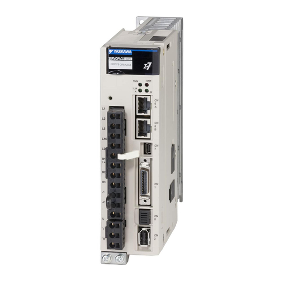
1 Introduction 1.2 Sigma-7Siec Appearance The following figure shows the external appearance of the Sigma-7Siec controller. Switches (under cover) LED Indicators CN6A/B: Ethernet Main Circuit Power Supply Control Circuit CN7: USB Power Supply Regenerative Resistor CN1: SERVOPACK I/O Connections CN8: HWBB... -
Page 7: Model Number Designation
11th+12th+13th digits FT/EX Specification 0.4 kW 5th+6th digits Interface 0.5 kW Code Specification Code Specification 0.75 kW Application function for Sigma-7Siec Sigma-7Siec 1.0 kW Three- (built-in single-axis control) phase, 1.5 kW 2.0 kW 3.0 kW 7th digit Design Revision Order 5.0 kW... - Page 8 1 Introduction...
-
Page 9: Specifications And Settings
2 Specifications and Settings 2 Specifications and Settings 2.1 Specifications Item Specification Control Method IGBT-based PWM control, sine wave current drive Serial encoder: 20 bits or 24 bits (incremental encoder/ With Rotary absolute encoder) Servomotor 22 bits (absolute encoder) Feedback •... - Page 10 2 Specifications and Settings (cont?d) Item Specification 1:5000 (At the rated torque, the lower limit of the speed control Speed Control Range range must not cause the Servomotor to stop.) ±0.01% of rated speed max. (for a load fluctuation of 0% to 100%) Coefficient of 0% of rated speed max.
- Page 11 2 Specifications and Settings (cont?d) Item Specification Inter- A JUSP-JC001 Communications Unit is required to connect to a faces Digital Operator (JUSP-OP05A-1-E). RS-422A Com- Commu- Up to N = 15 stations possible for RS-422A port muni- nica- cations tions (CN502) Axis Addres Communica-...
-
Page 12: Dip Switch Settings
2 Specifications and Settings 2.2 DIP Switch Settings DIP Switches Rotary Switches (used to set IP address) Rotary Switch 1 Rotary Switch 0 Setting for Switch Name Setting Operating Mode Normal Details Operation User program execution inhibited STOP Inhibits user program execution Normal operation Firmware programming Enables servo controller firmware... -
Page 13: Rotary Switches
2 Specifications and Settings 2.3 Rotary Switches When DIP switch 4 (E-INIT) is OFF, the rotary switches are ignored. The IP address is set from configuration settings stored on the servo controller. Rotary switches are normally used to set the IP address. This is the case when DIP switch 4 (E-INIT) is ON ... - Page 14 2 Specifications and Settings...
-
Page 15: Installation Standards
3 Installation Standards 3 Installation Standards 3.1 Mechanical Installation/Dimensions The Sigma-7Siec servo interface is based on the Sigma-7S EtherCAT servo amplifier. As such, it has the same envelope and mechanical installation directions. Please refer to section 2.3 of the Sigma-7S EtherCAT (CoE) Communications Reference Product... -
Page 16: Installing Multiple Servopacks In A Con- Trol Panel
3 Installation Standards 3.2 Installing Multiple SERVOPACKS in a Con- trol Panel Provide the following intervals between the SERVOPACKs and spaces around the SERVOPACKs. Install cooling fans above the SERVOPACKs so that hot spots do not occur around the SERVOPACKs. Provide sufficient intervals and spaces as shown in the following figure to enable cooling by the fans and natural convec- Important... -
Page 17: Inputs And Outputs
4 Inputs and Outputs 4 Inputs and Outputs 4.1 Input Signals Default settings are provided in parentheses Signal Name Function General-purpose Sequence /SI1 You can allocate the input signal to use with Input 1 (Forward Drive Prohibit (P-OT) a parameter. Input) (Stops Servomotor drive (to prevent over- General-purpose Sequence... -
Page 18: Output Signals
4 Inputs and Outputs 4.2 Output Signals Default settings are provided in parentheses Signal Name Function ALM+ Servo Alarm Output Turns OFF (opens) when an error is detected. ALM- /SO1+ General-purpose You can allocate the output signal to use with a parameter. (/BK+) Sequence Output 1 (Controls the brake. -
Page 19: I/O Signal Connector (Cn1) Pin Arrangement
4 Inputs and Outputs 4.3 I/O Signal Connector (CN1) Pin Arrange- ment The following figure gives the pin arrangement of the of the I/O signal connector (CN1) for the default settings. General- Battery for /SO1+ purpose Absolute BAT+ General- (/BK+) Sequence Encoder Battery for... -
Page 20: I/O Signal Wiring Examples
* 2. Connect these when using an absolute encoder. If the Encoder Cable with a Battery Case is connected, do not connect a backup battery. * 3. The 24-VDC power supply is not provided by Yaskawa. Use a 24-VDC power supply with double insulation or reinforced insulation. - Page 21 Frame ground * 1. represents twisted-pair wires. * 2. The 24-VDC power supply is not provided by Yaskawa. Use a 24-VDC power supply with double insulation or reinforced insulation. * 3. Always use line receivers to receive the output signals.
-
Page 22: I/O Circuits
4 Inputs and Outputs 4.5.1 Sequence Input Circuits 4.5 I/O Circuits 4.5.1 Sequence Input Circuits Photocoupler Input Circuits This section describes CN1 connector terminals 6 to 13. Examples for Open-Collector Examples for Relay Circuits Circuits SERVOPACK SERVOPACK Ω 4.7 k Ω... - Page 23 4 Inputs and Outputs 4.5.2 Sequence Output Circuits 4.5.2 Sequence Output Circuits Incorrect wiring or incorrect voltage application to the output circuits may cause short-circuit failures. If a short-circuit failure occurs as a result of any of these causes, the Important holding brake will not work.
- Page 24 4 Inputs and Outputs 4.5.2 Sequence Output Circuits...
-
Page 25: Led Outputs
5 LED Outputs 5 LED Outputs The following indicators show the operating status of the servo controller and error information. ERR: Solid at power up Off when there is no error Solid when there is an alarm ... - Page 26 5 LED Outputs...
-
Page 27: Ethernet Connectivity
6 Ethernet Connectivity 6 Ethernet Connectivity The Sigma-7Siec supports both 100 Mbps/100Base-TX and 10 Mbps/ 10Base-T connections. One single network is accessed using both CN6A and CN6B. The same IP address is set for both ports. The Ethernet address (MAC address) can be found on the nameplate. -
Page 28: Ethernet Cable
6 Ethernet Connectivity 6.2 Ethernet Cable For the Ethernet cable, use a twisted pair cable with RJ-45 connector. Yaskawa strongly recommends the use of shielded ethernet cables (Yaskawa model JZSP-CM3RRM0-xx-E). Ethernet ports are capable of auto-crossover, so crossover cables are not necessary. - Page 29 6 Ethernet Connectivity Connection Example 2 Sigma-7Siec Sigma-7Siec 100 Base-TX (up to 100m) Station Connection Example 3 Sigma-7Siec Sigma-7Siec Station Core 100Base-TX Core 100Base-TX Ethernet Switch Servo motor...
- Page 30 1. Locate Ethernet cables so that they are well-separated from power cables or other sources of EMI 2. Yaskawa strongly recommends the use of high-quality shielded Ethernet cables such as JZSP-CM3RRM0-xx-E 3. Attach ferrite cores to Ethernet cables that are subjected to EMI...
-
Page 31: Sbk-U-Vba-Xx
7 Cable Diagrams 7 Cable Diagrams 7.1 SBK-U-VBA-xx Terminal Block - CN1 I/O. SBK-U-VBA-xx Function Chart for Sigma-5 or Sigma-7 Servo Amplifier Mechatrolink-II type Servo Amplifier / Option type Pin No. Signal Function /BK+ (/SO1+) Brake interlock output (+) (General purpose output 1 (+)) /BK- (/SO1-) Brake interlock output (-) (General purpose output 1 (-)) ALM+... -
Page 32: Jzsp-Csi02-X-E
7 Cable Diagrams 7.2 JZSP-CSI02-x-E Flying Lead - CN1 I/O. SERVOPACK End Connector 10126 - 6000 EL ( by Sumitomo 3 M Ltd. ) Shell 10326 - 52 A 0 - 008 Cable ( Ivory ) SSRFPVV-SB AWG# 28 13 P ×... -
Page 33: Emc Installation Conditions
The EMC installation conditions that are given here are the conditions that were used to pass testing criteria at Yaskawa. The EMC level may change under other conditions, such as the actual installation structure and wiring conditions. These Yaskawa products are designed to be built into equipment. - Page 34 8 EMC Installation Conditions • Single-Phase, 200 VAC Shield box Brake power supply SERVOPACK Brake U, V, and W Power supply: Noise L1 and L2 Single-phase, 200 VAC filter Servomotor L1C and L2C Surge absorber Encoder Clamp Host controller CN6A and CN6B Clamp Clamp Safety...
- Page 35 8 EMC Installation Conditions • Single-Phase, 100 VAC Shield box Brake power supply SERVOPACK Brake U, V, and W Power supply: Noise L1 and L2 Single-phase, 100 VAC filter Servomotor L1C and L2C Surge absorber Encoder Clamp Host controller CN6A and CN6B Clamp Clamp Safety...
- Page 36 8 EMC Installation Conditions...
- Page 38 Phone: 81-3-5402-4511 Fax: 81-3-5402-4580 http://www.yaskawa.co.jp YASKAWA AMERICA, INC. 2121 Norman Drive South, Waukegan, IL 60085, U.S.A. Phone: (800) YASKAWA (800-927-5292) or 1-847-887-7000 Fax: 1-847-887-7310 http://www.yaskawa.com YASKAWA ELÉTRICO DO BRASIL, LTDA. Avenida Piraporinha 777, Diadema, São Paulo, 09950-000, Brasil Phone: 55-11-3585-1100 Fax: 55-11-3585-1187 http://www.yaskawa.com.br...
Need help?
Do you have a question about the Sigma-7Siec and is the answer not in the manual?
Questions and answers