
Related Manuals for YASKAWA SI-ES3


Summary of Contents for YASKAWA SI-ES3
- Page 1 EtherCAT Option Options Card for AC Drives and Regenerative Units Installation Manual Type: SI-ES3 SI-ES3/V...
- Page 2 This Page Intentionally Blank YASKAWA TOEPYEUOEC101A EtherCAT Option Installation Manual...
-
Page 3: Table Of Contents
EtherCAT Option SI-ES3/V for V1000 ........ - Page 4 Revision History........... 27 YASKAWA TOEPYEUOEC101A EtherCAT Option Installation Manual...
-
Page 5: Preface And General Precautions
Note: Be aware that serious injury or death may result if the warnings described in this manual are not observed. Yaskawa assumes no respon- sibility for injuries or equipment damage to your company or customers that are caused by a failure to observe the information contained in this manual. -
Page 6: Intended Use
RCM/RCD. Wait for the time specified on the warning label at a minimum and make sure that all indica- tors are OFF. Then check the wiring and peripheral device ratings to find the cause of the problem. Contact Yaskawa before en- ergizing the drive or peripheral devices if the cause is not known. -
Page 7: Legal Information
Electrical Shock Hazard. Do not make changes to the drive body or drive circuitry. Failure to obey can cause death or serious injury and will void warranty. Yaskawa is not responsible for changes to the product made by the user. -
Page 8: Receiving
• If you have received the wrong option card model or the Communication Option card does not function prop- erly, contact your supplier. ◆ Packaging Content Table 3.1 Option Package Contents for SI-ES3 (AC Drives and Regenerative Units) Description Option Card Ground Cables... -
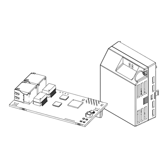
Page 9: Ethercat Option Components
I - Connector (CN5) C - Model number D - Installation hole E - LED (RUN) Figure 4.1 Option Card ◆ EtherCAT Option SI-ES3/V for V1000 EtherCAT with cover attached EtherCAT with cover removed Underside L/A IN L/A OUT IN OUT... -
Page 10: Ethercat Option Status Leds
The option BOOT or APP firmware is executing the NOID firmware loader. (1 Hz or 6 Hz) 1 Hz: Firmware loader protocol in IDLE state (waiting for commands from drive) 6 Hz: Firmware loader protocol is processing commands YASKAWA TOEPYEUOEC101A EtherCAT Option Installation Manual... -
Page 11: Indicator Flash Rates
200 ms 1000 ms n flashes Figure 4.3 Meaning of LED Flash Rates ◆ Connecting the Option Card ■ Communication Connector The Communication Option card is connected to the network using a RJ45 connector. YASKAWA TOEPYEUOEC101A EtherCAT Option Installation Manual... -
Page 12: Mechanical & Electrical Installation
Electrical Shock Hazard. Do not make changes to the drive body or drive circuitry. Failure to obey can cause death or serious injury and will void warranty. Yaskawa is not responsible for changes to the product made by the user. -
Page 13: Preconditions For Installing The Option Card
(G) of the front cover. Make sure no sharp edges remain. For Inverter drives 2A0056 to 0211, and 4A0031 to 0165: enough space to keep all wiring inside the unit is available. YASKAWA TOEPYEUOEC101A EtherCAT Option Installation Manual... -
Page 14: Installing The Option On A V1000
(screw size: M3) B - Ground Cable E - Drive-side connection (screw C - Wire size: M3.5 to M6) Figure 5.3 Connect Ground Wire Select shortest possible cable for ground connection. Re-attach the bottom cover. YASKAWA TOEPYEUOEC101A EtherCAT Option Installation Manual... - Page 15 D - Drive ground terminal Figure 5.5 Connect Ground Wire Connect the communication wire to the Communication Option card modular connector. Attach the cover to the front of the Communication Option card. Switch on the drive power supply. YASKAWA TOEPYEUOEC101A EtherCAT Option Installation Manual...
-
Page 16: Installing The Option On A Ga700
Figure 5.7 Affix the LED Label Turn off the power. Wait until the CHARGE LED turns off and then remove the cover. Refer to the drive manual for direction on removing the front cover. YASKAWA TOEPYEUOEC101A EtherCAT Option Installation Manual... - Page 17 Reattach and secure the LED Status Ring board (H). Use the open space provided inside the LED Status Ring board to route option wiring. Do not pinch cables between the front cover or the LED Status Ring board and the drive. YASKAWA TOEPYEUOEC101A EtherCAT Option Installation Manual...
-
Page 18: Installing The Option On A Q2A
For detailed information please refer to the Technical Manual of the inverter drive. Communication option cards can only be inserted into the CN5-A connector located on the drive control board. YASKAWA TOEPYEUOEC101A EtherCAT Option Installation Manual... - Page 19 Installing the option card on a Q2A drive requires only two screws and does not require a ground wire. The option package ships with three screws and a ground wire for installation on other drive series. Do not use the ground wire or the extra screw. YASKAWA TOEPYEUOEC101A EtherCAT Option Installation Manual...
-
Page 20: Esi File
For easy network implementation of drives equipped with a Communication Option card, the ESI file can be ob- tained from these sources: • Europe: http://www.yaskawa.eu.com • Japan: http://www.e-mechatronics.com • USA: http://www.yaskawa.com Note: For other areas, and when using Q2A AC drives, contact your sales representative. YASKAWA TOEPYEUOEC101A EtherCAT Option Installation Manual... -
Page 21: Ethercat Option Related Drive Parameters
If no torque reference/limit value is entered the motor will not produce torque. The default value depends on the drive used and/or the drive software version. For details refer to the technical manual for the drive. YASKAWA TOEPYEUOEC101A EtherCAT Option Installation Manual... -
Page 22: Parameters For Q2A
If the drive is set to receive the torque reference/limit from the network (F6-06 = 1) make sure the value is set appropriately by the controller. If no torque reference/limit value is entered the motor will not produce torque. YASKAWA TOEPYEUOEC101A EtherCAT Option Installation Manual... -
Page 23: Troubleshooting
Drive Profile DSP402 is used and a value is written to object 6042 (Hex) (vl Target Velocity) while the drive status is not "Operation Enable". Object 2155 (Hex) is tried to be read while the SI-ES3 option is not in "Operational" state. -
Page 24: Minor Faults/Alarms
• If the problem continues, replace either the control board or the entire drive. For instructions on replacing the control board, contact Yaskawa or your nearest sales representative. Termination resistor setting for MEMOBUS/Mod- Enable the termination resistor in the last drive in a MEMOBUS/ bus communications is incorrect. -
Page 25: Specifications
NOID processing mode, process resp data is active, ctrl data is on hold (Until MEMOBUS process is complete) Online-PRG NOID processing mode, NO process (ctrl/resp) data is active Host YASKAWA AC drive or regenerative unit Light Emitting Diode OPT, Option The unit described in this document... - Page 26 EEP..............24 Fault ..............24 Fault ..............23 Minor Fault............. 24 oFA00 ..............24 oFA01 ..............24 oFA30 to oFA43 ............24 oFb00 ..............24 oFb02 ..............24 oFC00 ..............24 oFC02 ..............24 YASKAWA TOEPYEUOEC101A EtherCAT Option Installation Manual...
- Page 27 Revision History Date of Revision Section Revised Content Publication Number August 2018 – First Edition – Contains information for A/V1000, D/R/U1000, GA700, and Q2A. YASKAWA TOEPYEUOEC101A EtherCAT Option Installation Manual...
- Page 28 Specifications are subject to change without notice for ongoing product modifications and improvements. Original instructions. © 2018 YASKAWA Europe GmbH TOEPYEUOEC101 YASKAWA Europe GmbH Revision: A <0>-0...
Need help?
Do you have a question about the SI-ES3 and is the answer not in the manual?
Questions and answers