Advertisement
Quick Links
Advertisement

Subscribe to Our Youtube Channel
Related Manuals for YASKAWA Sigma II Series


Summary of Contents for YASKAWA Sigma II Series
- Page 1 Sigma II Series Servo System User’s Manual...
- Page 2 Yaskawa. No patent liability is assumed with respect to the use of the information contained herein. Moreover, because Yaskawa is constantly striving to improve its high-quality products, the information contained in this man- ual is subject to change without notice.
- Page 3 Chapter 2: Installation Overview........................viii Using This Manual......................ix Safety Precautions......................x Checking Product and Part Names ..............1-1 1.1 Checking the Sigma II Series Products on Deliver..........1-2 1.1.1 Servomotors ....................1-2 1.1.2 Servo Amplifiers..................1-4 1.2 Product Part Names ..................... 1-5 1.2.1...
- Page 4 Sigma II User’s Manual Chapter 2: Installation 3.3 Main Circuit Wiring..................... 3-7 3.3.1 Names and Descriptions of Main Circuit Terminals........3-8 3.3.2 Typical Main Circuit Wiring Example............3-9 3.3.3 Cable Specifications and Peripheral Devices ..........3-9 3.3.4 Servo Amplifier Power Losses ..............3-10 3.3.5 Wiring Main Circuit Terminal Blocks ............
- Page 5 Sigma II User’s Manual Chapter 2: Installation Parameter Settings and Functions................ 5-1 5.1 Settings According to Device Characteristics ............ 5-4 5.1.1 Switching Servomotor Rotation Direction ..........5-4 5.1.2 Setting the Overtravel Limit Function ............5-5 5.1.3 Limiting Torques..................5-9 5.2 Settings According to Host Controller.............. 5-14 5.2.1 Speed Reference ..................
- Page 6 Sigma II User’s Manual Chapter 2: Installation 5.5.4 Speed Coincidence Output................ 5-74 5.5.5 Using the Running Output Signal ............. 5-75 5.5.6 Using the Servo Ready Output Signal ............5-76 5.5.7 Using the Warning Output Signal ............. 5-77 5.5.8 Using the Near Output Signal ..............5-79 5.5.9 Handling Power Loss................
- Page 7 Sigma II User’s Manual Chapter 2: Installation 6.2 High-speed Positioning..................6-7 6.2.1 Setting Servo Gain ..................6-7 6.2.2 Using Feed-Forward Control ..............6-9 6.2.3 Using Proportional Control................. 6-9 6.2.4 Setting Speed Bias ..................6-10 6.2.5 Using Mode Switch .................. 6-11 6.2.6 Speed Feedback Compensation ..............
- Page 8 Sigma II User’s Manual Chapter 2: Installation 7.2.4 Manual Adjustment of the Speed and Torque Reference Offset ....7-29 7.2.5 Clearing Alarm Traceback Data ............... 7-34 7.2.6 Checking the Motor Model............... 7-36 7.2.7 Checking the Software Version..............7-39 7.2.8 Origin Search Mode.................. 7-40 7.2.9 Initializing Parameter Settings..............
- Page 9 Sigma II User’s Manual Chapter 2: Installation A.5 Connecting OMRON's C500-NC112 Position Control Unit ......A-6 A.6 Connecting MITSUBISHI's AD72 Positioning Unit.......... A-7 A.7 Connecting MITSUBISHI's AD75 Positioning Unit.......... A-8 List of Parameters ....................B-1 B.1 Parameters......................B-2 B.2 Switches .......................B-5 B.3 Input Signal Selections ..................B-9 B.4 Output Signal Selections..................B-11 B.6 Monitor Modes ....................B-12...
- Page 10 Related Manuals Refer to the following manuals as required. Read this manual carefully to ensure the proper use of Sigma II Series servodrives. Also, keep this manual in a safe place so that it can be referred to whenever necessary.
- Page 11 Sigma II User’s Manual Table of Contents/Preface Using This Manual Intended Audience This manual is intended for the following users. • Those designing Sigma IΙ Series servodrive systems. • Those installing or wiring Sigma IΙ Series servodrives. • Those performing trial operation or adjustments of Sigma IΙ Series servodrives. •...
- Page 12 Improper grounding may result in electric shock or fire. • Required for 7.5kW amplifiers: use of Yaskawa kit Number XXX for wiring the power input and output terminals, or equivalent UL listed closed-loop ring terminals designed to accept 4 AWG wires.
- Page 13 Sigma II User’s Manual Table of Contents/Preface Operation CAUTION • Never touch any rotating motor parts while the motor is running. Doing so may result in injury CAUTION • Conduct trial operation on the servomotor alone with the motor shaft disconnected from machine to avoid any unexpected accidents.
- Page 14 The edition number appears on the front and back covers. • If the manual must be ordered due to loss or damage, inform your nearest Yaskawa representative or one of the offices listed on the back of this manual.
- Page 15 Chapter 1: Checking Products and Part Names Checking Product and Part Names This chapter describes the procedure for checking products upon delivery as well as names for product parts. 1.1 Checking the Sigma II Series Products on Deliver..........1-2 1.1.1 Servomotors ....................1-2 1.1.2 Servo Amplifiers..................
- Page 16 Are there any loose screws? Check screws for looseness using a screwdriver. If any of the above are faulty or incorrect, contact Yaskawa or an authorized distributor. 1.1.1 Servomotors External Appearance and Nameplate Example...
- Page 17 Sigma II User’s Manual Chapter 1: Checking Products and Part Names Model Numbers Standard Servomotors SGMPH - 01 A A A 2 S Sigma II Series Servomotor Name Brake and Oil Seal Specifications SGMAH 1: With brake, no oil seal SGMPH...
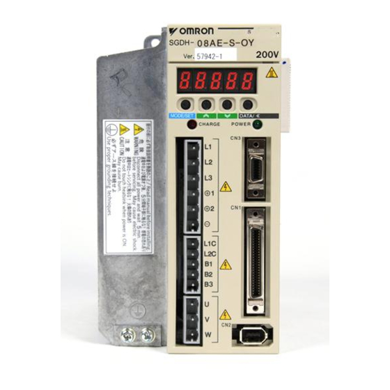
- Page 18 YASKAWA 200V SERVOPACK SGDH- MODE/SET DATA/ CHARGE POWER Serial number Sigma II series SGDH Applicable capacity servo amplifier Applicable power supply Model Numbers SGDH - 10 A E - o Sigma II Series SGDH Servo Amplifier Maximum Applicable Servomotor Capacity (See Table 1.9)
- Page 19 Sigma II User’s Manual Chapter 1: Checking Products and Part Names Table 1.4: Maximum Applicable Servomotor Capacity Maximum Applicable Servomotor Capacity Symbol Capacity (kW) Symbol Capacity (kW) 0.03 0.75 0.05 0.10 0.20 0.40 0.50 — —- 1.2 Product Part Names This section describes product part names.
- Page 20 Sigma II User’s Manual Chapter 1: Checking Products and Part Names 1.2.2 Servo Amplifiers The figure below shows the part names for servo amplifiers. Battery Holder Used to house the backup battery for an absolute encoder. CN5 Analog Monitor Connector Used to monitor motor speed, torque refer- ence, and other values through a special cable.
- Page 21 Sigma II User’s Manual Chapter 2: Installation Installation This chapter describes precautions for Sigma II Series servomotor and servo amplifier installation. 2.1 Servomotors ......................2-2 2.1.1 Storage Temperature ................... 2-2 2.1.2 Installation Site ................... 2-2 2.1.3 Alignment ....................2-3 2.1.4 Orientation ....................
- Page 22 Sigma II User’s Manual Chapter 2: Installation 2.1 Servomotors SGMoH servomotors can be installed either horizontally or vertically. The service life of the servomotor can be shortened or unexpected problems might occur if it is installed incorrectly or in an inappropriate location. Follow these installation instruc- tions carefully.
- Page 23 Sigma II User’s Manual Chapter 2: Installation • Free of corrosive or explosive gases. • Well-ventilated and free of dust and moisture. • Ambient temperature of 0 to 40°C. • Relative humidity (r.h.) of 20 to 80% with no condensation. •...
- Page 24 Sigma II User’s Manual Chapter 2: Installation 2.1.5 Allowable Shaft Loads Design the mechanical system so thrust and radial loads applied to the servomotor shaft end during operation falls within the ranges shown in Table 2.1. Allowable radial load in the table is the maximum load allowed on the end of the output shaft.
- Page 25 Sigma II User’s Manual Chapter 2: Installation 2.1.6 Handling Oil and Water Install a protective cover over the servomotor if it is used in a location that is subject to water or oil mist. Also use a servomotor with an oil seal when needed to seal the through-shaft section.
- Page 26 YASKAWA 200V SERVOPACK SGDH- MODE/SET DATA/ POWER CHARGE Sigma II series servo amplifier 2.2.2 Installation Site The following precautions apply to the installation site. Situation Installation Precaution Design the control panel size, unit layout, and cooling Installation in a Control...
- Page 27 Sigma II User’s Manual Chapter 2: Installation 2.2.3 Orientation Install the servo amplifier perpendicular to the wall as shown in the figure. The servo amplifier must be oriented this way because it is designed to be cooled by nat- ural convection or cooling fan. Secure the servo amplifier using the mounting holes.
- Page 28 Sigma II User’s Manual Chapter 2: Installation As shown in the figure above, allow sufficient space around each servo amplifier for cooling by cooling fans or natural convection. Side-by-side Installation When installing servo amplifiers side by side as shown in the figure above, allow at least 0.39in.
- Page 29 Sigma II User’s Manual Chapter 3: Wiring Wiring This chapter describes the procedure used to connect Sigma II Series products to peripheral devices and gives typical examples of main circuit wiring as well as I/O signal connections. 3.1 Connecting to Peripheral Devices............... 3-2 3.1.1 Single-Phase (100V or 200V) Main Circuit Specifications.......
- Page 30 Sigma II User’s Manual Chapter 3: Wiring 3.1 Connecting to Peripheral Devices This section provides examples of standard Sigma II Series product connections to peripheral devices. It also briefly explains how to connect each peripheral device.
- Page 31 Sigma II User’s Manual Chapter 3: Wiring 3.1.1 Single-Phase (100V or 200V) Main Circuit Specifications Connect the SGDH servo amplifier Host to a Yaskawa host controller or to Controller one made by another company. MEMOCON GL120, GL130 with a motion module. Power supply...
- Page 32 Sigma II User’s Manual Chapter 3: Wiring 3.1.2 Three-Phase (200V) Main Circuit Specifications Connect the SGDH servo amplifier Host to a Yaskawa host controller or to Controller one made by another company. MEMOCON GL120, GL130 with a motion module. Power supply...
- Page 33 Sigma II User’s Manual Chapter 3: Wiring 3.2 Servo Amplifier Internal Block Diagrams The following sections show internal block diagrams of the Servo Amplifiers. 3.2.1 30 to 400W (200V) and 30 to 200W (100V) Models Single-phase +10% 200 to 230 V -15% (50/60Hz) THS1...
- Page 34 Sigma II User’s Manual Chapter 3: Wiring 3.2.2 0.5kW to 1.5kW (200V) Models Three-phase +10% 200 to 230 V -15% B1 B2 B3 FAN1 (50/60Hz) +12V D2 D3 D4 AC Servomotor Noise filter CHARGE THS1 Gate drive over Voltage current protector Relay drive Gate drive Sensor...
- Page 35 Sigma II User’s Manual Chapter 3: Wiring 3.3 Main Circuit Wiring This section shows typical examples of main circuit wiring for Sigma II Series servo products, functions of main circuit terminals, and the power ON sequence. Observe the following precautions when wiring.
- Page 36 Sigma II User’s Manual Chapter 3: Wiring 3.3.1 Names and Descriptions of Main Circuit Terminals The following table gives the names and a description of main circuit terminals. Main Circuit Names and Description Terminal Name Description Symbol +10%, -15% 30 to 200W Single-phase 100 to 115V (50/60Hz) L1, L2 or L1,...
- Page 37 ON. This is required in order to initialize the servo amplifier. Power Supply 2.0s maximum Servo alarm (ALM) output signal 3.3.3 Cable Specifications and Peripheral Devices Refer to the Sigma II Series Servo System Catalog Supplement (No. G-MI#99001).
- Page 38 Sigma II User’s Manual Chapter 3: Wiring 3.3.4 Servo Amplifier Power Losses The following table shows servo amplifier power losses at the rated output. Servo Amplifier Power Losses at Rated Output Maximum Output Main Control Applicable Regenerative Total Main Current Circuit Circuit Servomot...
- Page 39 Sigma II User’s Manual Chapter 3: Wiring 3.3.5 Wiring Main Circuit Terminal Blocks Observe the following precautions when wiring main circuit terminal blocks. CAUTION • Remove the terminal block from the servo amplifier prior to wiring. • Insert only one wire per terminal on the terminal block. •...
- Page 40 Sigma II User’s Manual Chapter 3: Wiring 3.4 I/O Signals This section describes I/O signals for the SGDH servo amplifier 3-12...
- Page 41 Sigma II User’s Manual Chapter 3: Wiring 3.4.1 Examples of I/O Signal Connections The following shows a typical example of I/O signal connections. SGDH Servo Amplifier V-REF LPF* ALO1 Alarm code maximum output: ALO2 Operating voltage: 30V Operating current: 20mA T-REF LPF* ALO3...
- Page 42 Sigma II User’s Manual Chapter 3: Wiring 3.4.2 List of CN1 Terminals The following diagram shows the layout and specifications of CN1 terminals. CN1 Terminal Layout Speed coin- /V-CMP- cidence (/COIN-) detection TGON sig- /TGON+ output nal output Open-collec- TGON sig- tor reference /TGON SEN signal...
- Page 43 Sigma II User’s Manual Chapter 3: Wiring CN1 Specifications Specifications for Applicable Receptacles Servo Amplifier Solder Type Case Manufacturer Connectors 10250–52A2JL or Equivalent 50–p 10150–3000VE 10350–52A0–008 Sumitomo 3M Co. Right Angle Plug 3.4.3 I/O Signal Names and Functions The following section describes Servo Amplifier I/O signal names and functions. Input Signals Signal Name Function...
- Page 44 Sigma II User’s Manual Chapter 3: Wiring Signal Name Function Reference Input mode PULS Corresponds to refer- /PULS ence pulse input • Code + pulse string 5.2.1 SIGN Line–driver • CCW/CW pulse Open–collector /SIGN • Two–phase pulse (90° phase differential) Position Reference 14 Error counter clear: Clears the error counter during position control.
- Page 45 Sigma II User’s Manual Chapter 3: Wiring 3.4.4 Interface Circuits This section shows examples of servo amplifier I/O signal connection to the host control- ler. Interface for Reference Input Circuits Analog Input Circuit Analog signals are either speed or torque reference signals at the impedance below. •...
- Page 46 Sigma II User’s Manual Chapter 3: Wiring The following examples show how to select the pull-up resistor R1 so the input cur- rent, I, falls between 7 and 15mA. Application Examples R1 = 2.2kΩ with R1 = 1kΩ with R1 = 180Ω with = 24V ±5% = 12V ±5% = 5V ±5%...
- Page 47 Sigma II User’s Manual Chapter 3: Wiring See 3.5 Wiring to an Encoder for connection circuit examples. • Connecting to an Open-Collector Output Circuit Alarm code signals are output from open-collector transistor output circuits. Connect an open-collector output circuit through a photocoupler, relay, or line receiver circuit.
- Page 48 Sigma II User’s Manual Chapter 3: Wiring 3.5 Wiring Encoders The following sections describe the procedure for wiring a Servo Amplifier to the encoder. 3.5.1 Connecting an Encoder (CN2) and Output Signals from the Servo Amplifier (CN1) The following diagrams show wiring for incremental and absolute encoders. Incremental Encoders Servo amplifier (Note)
- Page 49 The following encoder connectors are for the SGMGH and SGMSH servomotor: L-shaped plug: MS3108B20-29S Straight: MS3106B20-29S Cable clamp: MS3057-12A Note: Encoder cables are available from Yaskawa. For more details on the cables, see Sigma II Series Servo System Catalog Supplement (G-MI#99001). 3-21...
- Page 50 Sigma II User’s Manual Chapter 3: Wiring 3.6 Examples of Standard Connections The following diagrams show examples of standard servo amplifier connections by speci- fications and type of control. 3-22...
- Page 51 Sigma II User’s Manual Chapter 3: Wiring 3.6.1 Single-Phase Power Supply Specifications Single-phase 200 to 230VAC Single-phase 100 to 115VAC (50/60Hz) (50/60 Hz) 1MCCB Alarm Power Power Noise filter processing Be sure to attach a surge suppressor to the excitation coil of the magnetic contactor and relay.
- Page 52 Sigma II User’s Manual Chapter 3: Wiring 3.6.2 Three-Phase Power Supply Specifications Three-phase 200 to 230VAC (50/60Hz) 1MCCB Alarm Power Power Noise filter processing Be sure to attach a surge suppressor to the excitation coil of the magnetic contactor and relay. Servomotor A (1) B (2)
- Page 53 3.6.3 Position Control Mode Three-phase 200 to 230VAC (50/60Hz) 1MCCB Alarm Power Power Noise filter processing Be sure to attach a surge suppressor to the excitation coil of the magnetic contactor and relay. Servomotor A (1) B (2) C (3) D (4) SGDH Servo Amplifier Optical...
- Page 54 Sigma II User’s Manual Chapter 3: Wiring 3.6.4 Speed Control Mode Three-phase 200 to 230VAC (50/60Hz) 1MCCB Alarm Power Power Noise filter processing Be sure to attach a surge suppressor to the excitation coil of the magnetic contactor and relay. Servomotor A (1) B (2)
- Page 55 Sigma II User’s Manual Chapter 3: Wiring 3.6.5 Torque Control Mode Three-phase 200 to 230 VAC (50/60 Hz) 1MCCB Alarm Power Power Noise filter processing Be sure to attach a surge suppressor to the excitation coil of the magnetic contactor and relay. Servomotor A (1) B (2)
- Page 56 Sigma II User’s Manual Chapter 4: Trial Operation Trial Operation This chapter describes a two-step trial operation. Be sure to complete step 1 before proceeding to step 2. 4.1 Two-Step Trial Operation ..................4-2 4.1.1 Step 1: Trial Operation for Servomotor without Load........ 4-3 4.1.2 Step 2: Trial Operation with the Servomotor Connected to the Machine..
- Page 57 4.1.1 and 4.1.2 for more details on the trial operation. Step 1: Trial Operation for Servomotor without Load Make sure the servomotor is wired properly and then turn the shaft prior to connecting the servomotor to the equipment. YASKAWA 200V SERVOPACK SGDM-...
- Page 58 Check servomotor wiring. • Check CN1 I/O signal wiring. Make sure the host controller and other adjustments are completed as much as possi- ble in step 1 (prior to connecting the servomotor to equipment). YASKAWA 200V SERVOPACK SGDH- MODE/SET DATA/...
- Page 59 Do not connect anything to the sha (no-load conditions). Secure the servomotor mounting plate to the equipment in order to prevent the servomotor from moving during operation. 2. Check the wiring. YASKAWA 200V SERVOPACK SGDH MODE/SET DATA/...
- Page 60 Sigma II User’s Manual Chapter 4: Trial Operation 4. Operate with the Panel Operator. YASKAWA 200V SERVOPACK SGDH- Panel operator MODE/SET DATA/ CHARGE POWER Operate the servomotor using the Panel Operator. Check to see if the servomotor runs normally. See 7.2.2 Operation Using the Digital Operator for more details on the procedure.
- Page 61 Sigma II User’s Manual Chapter 4: Trial Operation Input Signal Status LED Display OFF (high level) Top LED indicators light. ON (low level) Bottom LED indicators light. Note: The servomotor will not operate properly if the following signal lines are not wired correctly. Always wire them correctly.
- Page 62 Sigma II User’s Manual Chapter 4: Trial Operation b. Turn ON the servo ON signal. Display with the servo ON. Set /S-ON (CN1-40) to 0V. If normal, the servomotor will turn ON and the LED indicator on the front panel will display as shown above. If an alarm display appears, take appropriate action as described in 9.2 Troubleshooting.
- Page 63 Sigma II User’s Manual Chapter 4: Trial Operation 4. Reset the following parameters to change the motor speed or direction of rota- tion. Sets the reference speed input gain Pn300 See 5.2.1 Speed Reference. Selects the rotation direction. See 5.1.1 Switching Servomotor Rota- Pn000.0 tion Direction.
- Page 64 Sigma II User’s Manual Chapter 4: Trial Operation • List of Alarms: See 9.2.3 Alarm Display Table. • List of Parameters: See Appendix B List of Parameters. 4.1.2 Step 2: Trial Operation with the Servomotor Connected to the Machine WARNING Follow the procedure below for step 2 operation precisely as given.
- Page 65 Sigma II User’s Manual Chapter 4: Trial Operation 4.2 Supplementary Information on Trial Operation Always refer to this information before starting trial operation in the following instances: 4.2.1 Servomotor with Brakes 4.2.2 Position Control by Host Controller 4.2.1 Servomotors with Brakes Use servomotors with brakes for vertical shaft applications or when external force must be applied to the shaft to prevent rotation due to gravity or external force dur- ing a power loss.
- Page 66 Sigma II User’s Manual Chapter 4: Trial Operation 4.2.2 Position Control by Host Controller If position control from the host controller has not been confirmed, disconnect the servomo- tor from the equipment and perform a trial operation, otherwise the servomotor may run out of control.
- Page 67 Sigma II User’s Manual Chapter 4: Trial Operation Basic Parameters Pn000.1 Function Selection Basic Switches: Control Method Selection See 5.3.5 Speed Control Pn300 Speed Reference Input Gain See 5.2.1 Pn201 PG Divider See 5.2.3 Position Control Pn200.0 Reference Pulse Form See 5.2.2 Pn202 Electronic Gear Ratio (Numerator)
- Page 68 Sigma II User’s Manual Chapter 5: Parameter Settings and Functions Parameter Settings and Functions This chapter describes the procedure for setting and applying parameters. 5.1 Settings According to Device Characteristics ............ 5-4 5.1.1 Switching Servomotor Rotation Direction ..........5-4 5.1.2 Setting the Overtravel Limit Function ............
- Page 69 Sigma II User’s Manual Chapter 5: Parameter Settings and Functions 5.5.2 Using the Servo ON Input Signal ............. 5-71 5.5.3 Using the Positioning Completed Output Signal........5-72 5.5.4 Speed Coincidence Output................ 5-74 5.5.5 Using the Running Output Signal ............. 5-75 5.5.6 Using the Servo Ready Output Signal ............
- Page 70 Sigma II User’s Manual Chapter 5: Parameter Settings and Functions Before Reading this Chapter This chapter describes the use of each CN1 connector I/O signals in the SGDH servo amplifier as well as the procedure for setting the related parameters for the intended pur- poses.
- Page 71 Sigma II User’s Manual Chapter 5: Parameter Settings and Functions 5.1 Settings According to Device Characteristics This section describes the procedure for setting parameters according to the dimensions and performance of the equipment used. 5.1.1 Switching Servomotor Rotation Direction The servo amplifier has a Reverse Rotation Mode that reverses the direction of ser- vomotor rotation without rewiring.
- Page 72 Sigma II User’s Manual Chapter 5: Parameter Settings and Functions 5.1.2 Setting the Overtravel Limit Function The overtravel limit function forces movable equipment parts to stop if they exceed the allowable range of motion. Using the Overtravel Function To use the overtravel function, connect the overtravel limit switch input signal termi- nals shown below to the correct pins of the servo amplifier CN1 connector.
- Page 73 Sigma II User’s Manual Chapter 5: Parameter Settings and Functions Enabling/Disabling Input Signals Set the following parameters to specify whether input signals are used for overtravel or not. The default setting is “used.” Parameter Signal Setting Control Mode P-OT Signal Mapping Speed/Torque Control, Pn50A.3 Default Setting: 2...
- Page 74 Sigma II User’s Manual Chapter 5: Parameter Settings and Functions Parameter Signal Setting Control Mode Speed/Torque Control, Pn001.1 Overtravel Stop Mode Default Setting: 0 Position Control Stop Mode After stopping Pn001.1 Overtravel setting Stop by dynamic Pn001.0 = 0, 1 brake Coast Pn001.1 = 0...
- Page 75 Sigma II User’s Manual Chapter 5: Parameter Settings and Functions Stop Mode Stop by dynamic brake Forward run prohibit input Coast to a stop P-OT (CN1-42) Decelerate to a stop Reverse run prohibit input N-OT (CN1-43) Max. torque setting for an emergency stop Pn406 Servo OFF Stop Mode Selection...
- Page 76 Sigma II User’s Manual Chapter 5: Parameter Settings and Functions 5.1.3 Limiting Torques The SGDH servo amplifier limits torques as follows: • Level 1: Limits maximum output torque to protect the equipment or workpiece. • Level 2: Limits torque after the servomotor moves the equipment to a specified position (internal torque limit).
- Page 77 Sigma II User’s Manual Chapter 5: Parameter Settings and Functions Application Example: Equipment Protection Torque limit Too small a torque limit will result in a insufficient torque during acceleration and Motor deceleration. speed Torque Using the /CLT Signal The following section describes the use of the contact output signal /CLT as a torque limit output signal.
- Page 78 Sigma II User’s Manual Chapter 5: Parameter Settings and Functions Pn50F.0 Output terminal CN1-25, 26 (SO1) Torque limit CN1-27, 28 (SO2) detection CN1-29, 30 (SO3) Use the following table to select which terminal will output the /CLT signal. Output Terminal (CN1–) Parameter Setting Pn50F.0...
- Page 79 Sigma II User’s Manual Chapter 5: Parameter Settings and Functions This is the external torque (current) limit input for forward and reverse rotation. Check input signal allocation status when using this function. (See 5.3.3 Input Circuit Signal Allocation). Default settings are given in the table on the following page.
- Page 80 Sigma II User’s Manual Chapter 5: Parameter Settings and Functions Set the torque limits when the torque is limited by an external contact input. Setting Description /P-CL (CN1-45) Input Pn404 torque limit applied. /N-CL (CN1-46) Input Pn405 torque limit applied. See 5.2.9 Using Torque Limiting by Analog Voltage Reference.
- Page 81 Sigma II User’s Manual Chapter 5: Parameter Settings and Functions 5.2 Settings According to Host Controller This section describes the procedure for connecting a Sigma II Series servo to a host con- troller, including the procedure for setting related parameters. 5.2.1 Speed Reference Input the speed reference using the input signal Speed Reference Input.
- Page 82 Sigma II User’s Manual Chapter 5: Parameter Settings and Functions Parameter Pn300 can be used to change the voltage input range. Input Circuit Example Servo Amplifier 470Ω, ½W minimum 2kΩ + 12V CN1-5 CN1-6 • Always use twisted pair cable for noise control. Recommended variable resistor: Model 25HP-10B manufactured by Sakae Tsushin Kogyo Co., Ltd.
- Page 83 Sigma II User’s Manual Chapter 5: Parameter Settings and Functions Using the /P-CON Signal Speed Control, ð Input P-CON CN1-41 Proportional Control Reference Position Control The /P-CON input signal switches the Speed Control Mode from PI (proportional- integral) to P (proportional) control. Proportional control can be used in the following two ways: •...
- Page 84 Sigma II User’s Manual Chapter 5: Parameter Settings and Functions or equivalent Host controller Servo amplifier Photocoupler PULS CN1-7 Line-driver 150Ω /PULS CN1-8 SIGN CN1-11 /SIGN CN1-12 CN1-15 /CLR CN1-14 Connection Example 2: Open-collector Output Set limiting resistor R1 so that input current, I, falls within the following range: Host controller Servo amplifier Photocoupler...
- Page 85 Sigma II User’s Manual Chapter 5: Parameter Settings and Functions not isolated in this case. Servo Amplifier Host controller CN1-3 1kΩ +12V CN1-7 Photocoupler Approx. PULS 150Ω CN1-8 /PULS CN1-13 CN1-11 SIGN CN1-12 /SIGN ON: 1.5V maximum CN1-18 CN1-15 CN1-14 /CLR CN1-1 P represents twisted pair wires...
- Page 86 Sigma II User’s Manual Chapter 5: Parameter Settings and Functions Since the reference pulse form can be selected from among those listed below, set one according to host controller specifications. Input Parameter Reference Forward Rotation Reverse Rotation Pulse Logic Pn200.0 Pulse Form Reference Reference...
- Page 87 Sigma II User’s Manual Chapter 5: Parameter Settings and Functions Example of I/O Signal Generation Timing Servo ON t1 ≤ 30ms Release t2 ≤ 6ms Baseblock (when parameter Pn506 is set to 0) CN1-1 t3 ≥ 40ms Sign+pulse train CN1- t4, t5, t6 ≤...
- Page 88 Sigma II User’s Manual Chapter 5: Parameter Settings and Functions Error Counter Clear Input The procedure for clearing the error counter is described below. ð Input CLR CN1-15 Clear Input Position Control ð Input /CLR CN1-14 Clear Input Position Control The following occur when the CLR signal is set to high level.
- Page 89 Sigma II User’s Manual Chapter 5: Parameter Settings and Functions 5.2.3 Using the Encoder Signal Output Encoder output signals divided inside the servo amplifier can be output externally. These signals can be used to form a position control loop in the host controller. Servo amplifier Host controller (Servomotor)
- Page 90 Sigma II User’s Manual Chapter 5: Parameter Settings and Functions I/O Signals I/O signals are described below. Speed/Torque Control, Output ð PAO CN1-33 Encoder Output Phase A Position Control Speed/Torque Control, Output ð /PAO CN1-34 Encoder Output Phase /A Position Control Speed/Torque Control, Output ð...
- Page 91 Sigma II User’s Manual Chapter 5: Parameter Settings and Functions ð Input SEN CN1-4 SEN Signal Input Speed/Torque Control ðInput /SEN CN1-2 Signal Ground Speed/Torque Control Speed/Torque Control, Output ð PSO CN1-48 Encoder Output Phase S Position Control Speed/Torque Control, Output ð...
- Page 92 Sigma II User’s Manual Chapter 5: Parameter Settings and Functions The setting range varies with the encoder used. Preset value: 16 Setting Example 1 revolution Servomotor Model Number of Encoder Resolution and Encoder Pulses Per Revolution Setting Range (Bits) Specifications (p/rev) 2048 16 to 2048...
- Page 93 External power supply specifications: 24V ±1 V , 50mA minimum. Yaskawa recommends using the same type of external power supply as that used for output circuits. The function allocation for sequence input signal circuits can be changed. See 5.3.3 Input Circuit Signal Allocation for more details.
- Page 94 Host controller Note: Provide a separate external I/O power supply; the servo amplifier does not have an internal 24V power supply. Yaskawa recommends using the same type of external power supply as that used for input circuits. Function allocation for some sequence output signal circuits can be changed.
- Page 95 Sigma II User’s Manual Chapter 5: Parameter Settings and Functions 5.2.5 Using the Electronic Gear Function The electronic gear function enables the servomotor travel distance per input refer- ence pulse to be set to any value. It allows the pulses generated by the host control- ler to be used for control without having to consider the equipment gear ratio or the number of encoder pulses.
- Page 96 Sigma II User’s Manual Chapter 5: Parameter Settings and Functions Note: The number of bits representing the resolution of the applicable encoder is not the same as the num- ber of encoder signal pulses (A and B phase) output from the servo amplifier. 3.
- Page 97 Sigma II User’s Manual Chapter 5: Parameter Settings and Functions 5. Electronic gear ratio is given as: --- - If the gear ratio of the motor and the load shaft is given as: where m is the rotation of the motor and n is the rotation of the load shaft, ×...
- Page 98 Sigma II User’s Manual Chapter 5: Parameter Settings and Functions Electronic Gear Setting Examples The following examples show electronic gear settings for different load mecha- nisms. Ball Screws 0.24in. Reference unit: 0.001mm Travel distance per load shaft revolution = = 6000 Load shaft 0.0004in.
- Page 99 Sigma II User’s Manual Chapter 5: Parameter Settings and Functions Control Block Diagram The following diagram illustrates a control block for position control. Servo Amplifier (position control) Pn109 Pn202 Pn10A Pn107 Feed- Differentiation Primary forward gain lag filter Bias Pn108 Pn203 Bias addition Pn200.0...
- Page 100 Sigma II User’s Manual Chapter 5: Parameter Settings and Functions Using Contact Input Speed Control Follow steps 1 to 3 below to use the contact input speed control function. 1. Set contact input speed control as shown below. Parameter Signal Setting Control Mode Speed/Torque Control,...
- Page 101 Sigma II User’s Manual Chapter 5: Parameter Settings and Functions 2. Set the motor speeds with the following parameters. Setting Parameter Signal Control Mode (rpm) Speed 1 (SPEED 1) Range: 0 to 10000 Pn301 Speed Control (Contact Input Speed Control) Default Setting: 100 Speed 2 (SPEED 2) Range: 0 to 10000...
- Page 102 Sigma II User’s Manual Chapter 5: Parameter Settings and Functions ation setting. Speed reference Soft start Maximum speed Servo amplifier internal speed reference Pn305: Sets this time interval. Maximum speed Pn306: Sets this time interval. Smooth speed control can be performed by entering a progressive speed refer- ence or using contact input speed control.
- Page 103 Sigma II User’s Manual Chapter 5: Parameter Settings and Functions Use the following table when contact input speed control is used. Contact Signal Parameter Selected Speed /P-CON /P-CL /N-CL Pn000.1 (/SPD-D) (/SPD-A) (/SPD-B) Stopped by an inter- nal speed reference of 0.
- Page 104 Sigma II User’s Manual Chapter 5: Parameter Settings and Functions Example of Contact Input Speed Control Operation The following example shows operation by contact input speed control. Using the soft start function reduces physical shock when the speed is changed. Motor speed Speed 3 +SPEED 3...
- Page 105 Sigma II User’s Manual Chapter 5: Parameter Settings and Functions 5.2.7 Using Torque Control The SGDH servo amplifier limits torque as shown below. • Level 1: Limits maximum output torque to protect the equipment or workpiece. • Level 2: Limits torque after the Servomotor moves the equipment to a specified position (internal torque limit).
- Page 106 Sigma II User’s Manual Chapter 5: Parameter Settings and Functions Application Examples • Tension control • Pressure control Control Mode Pn000.1 Torque Control Servo amplifier This is a dedicated Torque Control Mode. •A torque reference is input from T-REF (CN1-9). Torque T-REF •Speed reference input V-REF (CN1-5) cannot be...
- Page 107 Sigma II User’s Manual Chapter 5: Parameter Settings and Functions Pn000.1 Control Method Speed Control: When /P-CON (/C-SEL) is ON Set the parameter Pn002.0 as shown below. Parameter Speed Reference Torque Reference Input Pn002.0 Input Comments (T-REF) (CN1-9,10) State (V-REF) (CN1-5,6) Speed Control Speed Reference Cannot be used.
- Page 108 Sigma II User’s Manual Chapter 5: Parameter Settings and Functions Input Signals Torque Reference Inputs The following input signals are used for torque control. Servo Amplifier T-REF CN1-9 Torque Torque reference input CN1-10 reference (Analog voltage input) V-REF CN1-5 Speed Speed reference input CN1-6 reference...
- Page 109 Sigma II User’s Manual Chapter 5: Parameter Settings and Functions Example of an Input Circuit Servo Amplifier 470Ω 1/2W minimum +12V 2kΩ T-REF CN1-9 CN1-10 Note: • Always use twisted pair cables for noise control. • Recommended variable resistor: Model 25HP–10B manufactured by Sakae Tsushin Kogyo Co., Ltd.
- Page 110 Sigma II User’s Manual Chapter 5: Parameter Settings and Functions Torque Control Parameter The following parameter is used for torque control. Set the parameter according to requirements of the servo system that is used. Setting Parameter Signal Control Mode (0.1V x rated torque) Setting Range: 10 to 100 Pn400 Torque Reference Input Gain...
- Page 111 Sigma II User’s Manual Chapter 5: Parameter Settings and Functions limit depends on the load condition. Motor speed Speed limit range V-REF Setting Parameter Signal Control Mode (no units) Speed Reference Input Adjust- Setting Range: 150 to 3000 Pn300 ment Factor (SRF) Speed/Torque Control Default Setting: 600 (0.01V ×...
- Page 112 Sigma II User’s Manual Chapter 5: Parameter Settings and Functions reference signal to T-REF (CN1-9 and 10). Host controller SGDH Servo Amplifier T-REF Differ Pn400 Servomotor ential V-REF Pn300 Pn100 Current loop Integration (Pn101) Speed calculation Position reference Encoder Divider Using the Torque Feed-Forward Function To use the torque feed-forward function, set the following parameter to 2.
- Page 113 Sigma II User’s Manual Chapter 5: Parameter Settings and Functions 5.2.9 Torque Limiting 2 by Analog Voltage Reference Torque limiting 2 by analog voltage reference limits torque by assigning a torque analog voltage to the T-REF terminal (CN1-9 and 10). It cannot be used for torque control because the torque reference input terminal T-REF is used as an input termi- nal.
- Page 114 Sigma II User’s Manual Chapter 5: Parameter Settings and Functions settings. Input Signal Level Description Comments Signal Limit value: either Pn404 or CN1-45 is at “L” level when Torque is limited at forward T-REF input, whichever is run side. smaller. /P-CL Torque is not limited at for- —...
- Page 115 Sigma II User’s Manual Chapter 5: Parameter Settings and Functions 5.2.10 Reference Pulse Inhibit Function (INHIBIT) This function inhibits the servo amplifier from counting input reference pulses dur- ing position control. The servomotor remains locked (clamped) while the function is in use.
- Page 116 Sigma II User’s Manual Chapter 5: Parameter Settings and Functions Setting Up the Servo Amplifier This section describes the procedure for setting parameters to operate the SGDH servo amplifier. 5.3.1 Parameters The Sigma IΙ Series servo amplifier provides many functions and has parameters that allow the user to specify functions and perform fine adjustments.
- Page 117 Pn50A.0 Setting Default setting for sequence input signal allocation. This setting is the same as Yaskawa SGDB-oADo servo amplifiers. Enables any sequence input signal settings. Note: The default setting for parameter Pn50A.0 is 0. Functions and applications in this manual are gener-...
- Page 118 Sigma II User’s Manual Chapter 5: Parameter Settings and Functions ally described for the factory defaults. Input Signal Allocation The following signal can be allocated when Pn50A.0 is set to 1. Servo amplifier /S-ON CN1-40 is default set for 40 (SI0) the /S-ON input signal.
- Page 119 Sigma II User’s Manual Chapter 5: Parameter Settings and Functions Pn50A. Description Setting Inputs the S-ON signal from the SI0 (CN1-40) input terminal. Inputs the/S-ON signal from the SI1 (CN1-41) input terminal. Signal polarity: Inputs the S-ON signal from the SI2 (CN1-42) input terminal. Inversion.
- Page 120 Sigma II User’s Manual Chapter 5: Parameter Settings and Functions Allocating Other Input Signals Input signal allocation can be changed as shown below. Input Signal Parameter Description Applicable Name Number Setting Logic Inputs the signal on the left from SI0 (CN1-40). Inputs the signal on the left from SI1 (CN1-41).
- Page 121 Sigma II User’s Manual Chapter 5: Parameter Settings and Functions 5.3.4 Output Circuit Signal Allocation Output signal functions can be allocated to the sequence signal output circuits shown below. CN1 Connector Default Setting Output Terminal Terminal Comments Name Symbol Name Numbers /V–CMP+ Speed coincidence...
- Page 122 Sigma II User’s Manual Chapter 5: Parameter Settings and Functions Parameter Output Signal Description Numbe Setting Disabled. (Not used for the output signal on the left.) Outputs the signal on the left from the SO1 (CN1-25 and 26) output terminal. Positioning Completed Pn50E.0 (/COIN)
- Page 123 Sigma II User’s Manual Chapter 5: Parameter Settings and Functions These settings specify which of the connector CN1 output signals are to be inverted: Parameter Output Terminal Description Number Setting Does not invert the signal. Pn512.0 (CN1-25, 26) Inverts the signal. Does not invert the signal.
- Page 124 Sigma II User’s Manual Chapter 5: Parameter Settings and Functions 5.3.5 Control Mode Selection The SGDH servo amplifier offers speed control, position control, torque control, and the other control modes shown in the following table. The following parameter is used to set the control mode. Setting Parameter Signal...
- Page 125 Sigma II User’s Manual Chapter 5: Parameter Settings and Functions Torque Control. Contact Input Speed Control Selection (Contact Reference) This mode uses the /P-CON (/SPD-D), /P-CL (/SPD-A), and /N-CL (/SPD-B) input signals to control speed as it switches among the three preset operating speeds in the servo amplifier.
- Page 126 Sigma II User’s Manual Chapter 5: Parameter Settings and Functions Torque Control (Analog Reference) ↔ ↔ Speed Control (Analog Ref- erence) This mode switches between torque and speed control through the /P-CON (/C-SEL) signal. See 5.2.7 Using Torque Control. Speed Control (Analog Reference) ↔ ↔...
- Page 127 Sigma II User’s Manual Chapter 5: Parameter Settings and Functions 5.4 Setting Stop Functions This section describes the procedure used to stop the servo amplifier properly. 5.4.1 Adjusting Offset When the Servomotor Will Not Stop The servomotor may rotate at very low speed and not stop even when 0V is specified as the reference voltage for servo amplifier speed and torque control (analog refer- ence).
- Page 128 Sigma II User’s Manual Chapter 5: Parameter Settings and Functions 5.4.2 Using the Dynamic Brake To stop the servomotor by applying the dynamic brake (DB), set the desired mode in the following parameter. The servomotor will stop due to equipment friction if the dynamic brake is not applied.
- Page 129 Sigma II User’s Manual Chapter 5: Parameter Settings and Functions 5.4.3 Using the Zero Clamp Function Zero Clamp Function The zero clamp function is used for systems where the host controller does not form a position loop for the speed reference input. In other words, this function is used to stop and lock the servomotor even when the input voltage of speed reference V-REF is not 0V.
- Page 130 Sigma II User’s Manual Chapter 5: Parameter Settings and Functions Control Mode Pn000.1 Setting Zero Clamp Control Mode This mode allows the zero clamp function to be set when the servomo- Servo amplifier tor stops. • The speed reference is input from V-REF (CN1–5).
- Page 131 Sigma II User’s Manual Chapter 5: Parameter Settings and Functions • Speed reference drops below the setting level of Pn501. V-REF speed reference Speed Preset value for zero clamping Time Closed (ON) /P-CON (/ZCLAMP) input Open (OFF) Zero clamp is performed Note: When the /ZCLAMP signal is allocated, the zero clamp operation will be used even for speed control (Pn000.1 = 0).
- Page 132 Sigma II User’s Manual Chapter 5: Parameter Settings and Functions example. Servomotor with brake Servo amplifier Power supply A (1) B (2) C (3) D (4) E (5) BK-RY CN1-o* F (6) (BK+) +24V CN2-o* /BK- Blue or BK-RY yellow White Black Brake power supplies are available...
- Page 133 Sigma II User’s Manual Chapter 5: Parameter Settings and Functions Pn50F.2 Input terminals CN1-25, 26 (SO1) Brake interlock CN1-27, 28 (SO2) output CN1-29, 30 (SO3) Select the /BK output terminal. Output Terminal (CN1) Parameter Setting Pn50F.2 Note: Signals are output with OR logic when multiple signals are allocated to the same output circuit. Set other output signals to a value other than that allocated to the /BK signal in order to output the /BK signal alone.
- Page 134 Sigma II User’s Manual Chapter 5: Parameter Settings and Functions Brake ON Timing If the equipment moves slightly due to gravity when the brake is applied, set the fol- lowing parameter to adjust brake ON timing. Setting Parameter Signal Description (10ms) Brake Reference Servo OFF Setting Range: 0 to 50...
- Page 135 Sigma II User’s Manual Chapter 5: Parameter Settings and Functions Holding Brake Setting Set the following parameters to adjust brake ON timing so the holding brake is applied when the servomotor stops. Parameter Signal Setting Description Brake Reference Output Speed Setting Range: 0 to 10000rpm Speed/Torque Control, Pn507...
- Page 136 Sigma II User’s Manual Chapter 5: Parameter Settings and Functions 5.5 Forming a Protective Sequence This section describes the procedure for using I/O signals from the servo amplifier to form a protective safety sequence. 5.5.1 Using Servo Alarm and Alarm Code Outputs The basic procedure for connecting alarm output signals is described below.
- Page 137 Sigma II User’s Manual Chapter 5: Parameter Settings and Functions The uses of open-collector output signals ALO1, ALO2 and ALO3 is described below. Speed/Torque Control, Output ð ALO1 CN1-37 Alarm Code Output Position Control Speed/Torque Control, Output ð ALO2 CN1-38 Alarm Code Output Position Control Speed/Torque Control,...
- Page 138 Sigma II User’s Manual Chapter 5: Parameter Settings and Functions 5.5.2 Using the Servo ON Input Signal The basic use and wiring procedure for the Servo ON (/S-ON) input signal (sequence input signal) is described below. Use this signal to forcibly turn OFF the servomotor from the host controller.
- Page 139 Sigma II User’s Manual Chapter 5: Parameter Settings and Functions Servopack The external short-circuit wiring shown CN1-40 (/S-ON) in the figure can be omitted if the Serv ON (/S-ON) input signal is not used. Pn50A.1 Status Result Setting Enables the servo ON The servo is OFF when CN-40 is open, and is ON when (/S-ON) input signal.
- Page 140 Sigma II User’s Manual Chapter 5: Parameter Settings and Functions ing is completed. Reference Servomotor Speed Pn500 Error pulse (Un008) /COIN (CN1-25) /COIN Status Result State Circuit between CN1–25 and 26 is Positioning is completed. (Position closed, and CN1–25 is at low level. error is below the setting.) Circuit between CN1–25 and 26 is Positioning is not completed.
- Page 141 Sigma II User’s Manual Chapter 5: Parameter Settings and Functions trol, and it is always ON for torque control. 5.5.4 Speed Coincidence Output The basic use and wiring procedures for the speed coincidence (/V-CMP) output sig- nal (photocoupler output signal), used to indicate a match with the speed reference, are described below.
- Page 142 Sigma II User’s Manual Chapter 5: Parameter Settings and Functions See 5.3.4 Output Circuit Signal Allocation for more details on parameter Pn50E. The following parameter is used to set conditions for speed coincidence output. Setting Parameter Signal Description (rpm) Speed Coincidence Signal Out- Setting Range: 0 to 100 Pn503 Speed Control...
- Page 143 Sigma II User’s Manual Chapter 5: Parameter Settings and Functions The parameter is default set so the /TGON signal is output between CN1-27 and 28. See 5.3.4 Output Circuit Signal Allocation for more details on parameter Pn50E. This parameter is used to set output conditions for the operation detection output sig- nal /TGON.
- Page 144 Sigma II User’s Manual Chapter 5: Parameter Settings and Functions This signal indicates that the servo amplifier has received the Servo ON signal and has completed all preparations. /S-RDY Status Result State Closed or low level. Servomotor is ready. Open or high level. Servomotor is not ready.
- Page 145 Sigma II User’s Manual Chapter 5: Parameter Settings and Functions The following parameter setting is used to change the CN1 connector terminal that outputs the /WARN signal. Parameter Signal Setting Description Speed/Torque Control, Pn50F Output Signal Selections 2 Default Setting: 0000 Position Control Pn50F.3 is used to allocate the /WARN output signals above.
- Page 146 Sigma II User’s Manual Chapter 5: Parameter Settings and Functions 5.5.8 Using the Near Output Signal The basic use and wiring procedures for the near (/NEAR) output signal (photocou- pler output signal) are described below. The signal is a sequence signal that is gener- ally output together with the positioning completed signal (/COIN), and it is used to indicate the servomotor is close to completing operation.
- Page 147 Sigma II User’s Manual Chapter 5: Parameter Settings and Functions alone. See 5.3.4 Output Circuit Signal Allocation. The following parameter is used to set the timing for /NEAR signal output. Setting Parameter Signal Description (reference unit*) Setting Range: 1 to 250 Pn504 NEAR Signal Width Position Control...
- Page 148 Sigma II User’s Manual Chapter 5: Parameter Settings and Functions In power loss detection, the status of the main circuit power supply is detected but the OFF status is ignored. So servomotor operation will continuous if the servomo- tor turns ON again within the time limit set at parameter Pn509. Power loss Power supply voltage...
- Page 149 Sigma II User’s Manual Chapter 5: Parameter Settings and Functions Selecting a Regenerative Resistor When the servomotor is driven in generator mode, power is returned to the servo amplifier side. This is called regenerative power. The regenerative power is absorbed by charging the smoothing capacitor, but when the capacitor charging energy is exceeded, the regener- ative power is further consumed by the regenerative resistor.
- Page 150 Sigma II User’s Manual Chapter 5: Parameter Settings and Functions External Regenerative Resistor 5.6.1 When installing an external regenerative resistor, a parameter setting must be changed as shown below. Setting Parameter Signal Description (x 10W) Setting Range: 0 to maximum Speed/Torque Control, Pn600 Regenerative Resistor Capacity...
- Page 151 Sigma II User’s Manual Chapter 5: Parameter Settings and Functions Servo amplifier Regenerative resistor Be sure to take out the lead wire between the B2 and B3 terminals. * The user must provide the regenerative resistor. Note: Adequate cooling must be provided for regenerative resistors because they reach very high tempera- tures.
- Page 152 Sigma II User’s Manual Chapter 5: Parameter Settings and Functions Servo Amplifier Capacity of 500W or More Servomotors with a capacity of 500W or more have built-in regenerative resistors. The allowable frequencies for just the servomotor during acceleration/deceleration operation, in the run cycle from 0 à maximum rotation speed à 0, are summarized in the following table.
- Page 153 Sigma II User’s Manual Chapter 5: Parameter Settings and Functions By Calculating the Regenerative Energy This section shows the procedure for calculating the regenerative resistor capacity when acceleration and deceleration operation is as shown in the following diagram. : Motor rotation speed Rotation speed : Load torque Motor torque...
- Page 154 Sigma II User’s Manual Chapter 5: Parameter Settings and Functions If the previous calculation determines that the amount of regenerative power (Wk) that can be processed by the built-in resistor is not exceeded, then an external regen- erative resistor is not required. If the amount of regenerative power that can be processed by the built-in resistor is exceeded, install an external regenerative resistor for the capacity obtained from the above calculation.
- Page 155 Sigma II User’s Manual Chapter 5: Parameter Settings and Functions • SGMPH Servomotor, 200V • SGMPH Servomotor, 100V SGMPH- SGMPH- Torque (%) Torque (%) • SGMGH Servomotor, 1500rpm 1600 1400 1200 SGMGH- 1000 30AoA 2oAoA 13AoA 09AoA 05AoA Torque (%) 5-88...
- Page 156 Sigma II User’s Manual Chapter 5: Parameter Settings and Functions • SGMSH Servomotor • 1200 SGMSH- 1000 Torque (%) Servo Amplifier’s Absorbable Energy The following diagrams show the relationship between the servoamp’s input power supply voltage and its absorbable energy. •...
- Page 157 Sigma II User’s Manual Chapter 5: Parameter Settings and Functions 5.7 Absolute Encoders If a motor with an absolute encoder is used, a system to detect the absolute position can be formed in the host controller. Consequently, automatic operation can be performed with- out zero return operation immediately after the power is turned ON.
- Page 158 Sigma II User’s Manual Chapter 5: Parameter Settings and Functions SEN Signals Servo amplifier Host controller 1000Ω CN1-4 Approx. 1mA 1µF 4.7kΩ at high level 7406 or equivalent OSEN CN1-2 • Wait at least three seconds after turning on the power before raising the SEN sig- nal to high level.
- Page 159 Sigma II User’s Manual Chapter 5: Parameter Settings and Functions play before returning the counter to 0. Parameter Signal Setting Description Setting Range: 0 to 65535 Speed/Torque Control, Pn205 Multi-turn Limit Setting Default Setting: 65535 Position Control • When Pn205 is set to the default (65535), multi-turn data varies in the range of −32768 to +32767.
- Page 160 Sigma II User’s Manual Chapter 5: Parameter Settings and Functions Battery Provided for Servo Amplifier Lithium battery: JZSP–BA01 (includes battery and connector) Battery: Toshiba, ER3 V, 3.6V, 1000mAh Battery carrying space Batter connector (CN8) WARNING • Install the battery at either the host controller or the servo amplifier, NEVER at both simultaneously. Such a connection would create a circuit between the batteries, which could lead to electric shock, injury, or equipment damage.
- Page 161 Sigma II User’s Manual Chapter 5: Parameter Settings and Functions key to change the number. 3. Press the DATA/ENTER key. The following display will appear. 4. Pressing the Up Arrow key will change the display as shown below. Con- tinue pressing the Up Arrow key until “PGCL5”...
- Page 162 Sigma II User’s Manual Chapter 5: Parameter Settings and Functions 2. Press the Up Arrow or Down Arrow key to select the parameter Fn008. 3. Press the DATA/SHIFT key, holding it down for at least one second. The fol- lowing display will appear. 4.
- Page 163 Sigma II User’s Manual Chapter 5: Parameter Settings and Functions Multi-turn Setup Using the Hand-held Digital Operator 1. Press the DSPL/SET key to select the auxiliary function mode. 2. Select the user function Fn013. Press the Left Arrow or Right Arrow key to select the digit to set, and then press the Up Arrow or Down Arrow key to change the number.
- Page 164 Sigma II User’s Manual Chapter 5: Parameter Settings and Functions 4. Press the MODE/SET key. The display will change as follows, and the absolute encoder’s multi–turn limit setting operation will be performed. Flashes for 1 second. 5. Press the DATA/SHIFT key to return to the auxiliary function mode. This completes the absolute encoder’s multi-turn limit setting operation.
- Page 165 Sigma II User’s Manual Chapter 5: Parameter Settings and Functions Signal Status Contents Serial data Initial State Initial incremental pulse Normal State Incremental pulse Initial State Initial incremental pulse Incremental pulse Normal State Home position pulse Rotation count serial data Contents of Absolute Data •...
- Page 166 Sigma II User’s Manual Chapter 5: Parameter Settings and Functions incremental pulse up/down counter to zero. 3. Receive eight bytes of serial data. 4. The system enters a normal incremental operation state approximately 50ms after the last serial data is received. Rotation count Initial incremental pulses SEN signal...
- Page 167 Sigma II User’s Manual Chapter 5: Parameter Settings and Functions PSO Serial Data Specifications The number of revolutions and the absolute position within one revolution are always output in five and seven digits, respectively. The data output cycle is approx- imately 40ms.
- Page 168 Sigma II User’s Manual Chapter 5: Parameter Settings and Functions This parameter sets the number of output pulses for PG output signals (PAO, /PAO, PBO, /PBO). Pulses from the motor encoder (PG) are divided by the number of pulses set here before being output.
- Page 169 5.8.1 Wiring Precautions To ensure safe and stable operation, always observe the following wiring precau- tions: 1. Always use the following cables for reference input and encoder wiring. Yaskawa Maximum Cable Type Drawing Number Allowable Length Reference Twisted–pair wires JZSP–CKI01...
- Page 170 Sigma II User’s Manual Chapter 5: Parameter Settings and Functions mechanism to prevent noise interference. 5. To prevent malfunction due to noise, take the following actions: • Position the input reference device and noise filter as close to the servo amplifier as possible.
- Page 171 Sigma II User’s Manual Chapter 5: Parameter Settings and Functions MCCB or Fuse According to Power Capacity The following table shows the MCCB or fuse capacity for each power supply capac- ity. Servo Amplifier Current Capacity per Main Circuit Power Capacity per Model MCCB or Fuse Power...
- Page 172 Sigma II User’s Manual Chapter 5: Parameter Settings and Functions Note: SGDH servo amplifiers do not have built-in ground protection circuits. To configure a safer system, install a ground fault interrupter with or without a circuit breaker for protection against overload and short circuit conditions.
- Page 173 SGDH–A3AE to –02AE SUP–P5H–EPR SGDH–A3BE to –01BE Okaya Electric Company SGDH–02BE SUP–P8H–EPR SGDH–04AE SUP–P10H–EPR SGDH–05AE to –20AE LF–3200 Tokin Corp. SGDH–30AE LF–3300 Note: Filters manufactured by Tokin Corp. are available from Yaskawa. Please contact Yaskawa or an authorized distributor. 5-106...
- Page 174 Sigma II User’s Manual Chapter 5: Parameter Settings and Functions Installation and Wiring a Noise Filter Incorrect application of a noise filter significantly reduces its benefits. Follow these instructions for the best results. • Separate the input lines from the output lines. Do not put the input and output lines in the same duct or bundle them together.
- Page 175 Sigma II User’s Manual Chapter 5: Parameter Settings and Functions • Connect the noise filter ground wire directly to the ground plate. Do not connect the noise filter ground wire to other ground wires. Filter Filter Shielded Thick and ground wire short •...
- Page 176 Sigma II User’s Manual Chapter 5: Parameter Settings and Functions 5.8.3 Using More Than One Servodrive The following diagram is an example of the wiring when more than one servodrive is used. Power Supply Power MCCB supply ON Power supply OFF Noise filter Fuse Fuse...
- Page 177 Sigma II User’s Manual Chapter 5: Parameter Settings and Functions noise filter that has enough capacity for the total power capacity (load conditions) of those servos. For details, refer to 5.8.1 Wiring Precautions. 5.8.4 Extending Encoder Cables Standard encoder cables have a maximum length of 20m. If a longer cable is required, prepare an extension cable as described below.
- Page 178 Sigma II User’s Manual Chapter 5: Parameter Settings and Functions • Preparing Encoder Cables • ïEncoder Connector • ïCable Line • ïEncoder Connector at Servomotor at Servo Amplifier For SGMAH and SGMPH servomotors For SGMGH and SGMSH servomotors Maximum length: 50 m (1968.50 in) 5-111...
- Page 179 Sigma II User’s Manual Chapter 5: Parameter Settings and Functions 5.8.5 400V Power Supply Voltage CAUTION • Do not connect the servo amplifier directly to any level other than 400V. Doing so will destroy the servo amplifier. There are three types of SGDH servo amplifiers, for the power supply voltages: sin- gle-phase 100V , three-phase 200V , and single-phase 200V...
- Page 180 Sigma II User’s Manual Chapter 5: Parameter Settings and Functions Single-phase Power Supply Connection Example Transformer for SGDH Servo amplifier voltage conversion 200V or 100V Electromagnetic contactor for power supply ON/OFF 5.8.6 Reactor for Harmonic Suppression SGDH servo amplifiers have DC reactor connection terminals for power supply har- monic suppression.
- Page 181 Sigma II User’s Manual Chapter 5: Parameter Settings and Functions DC Reactor Specifications The following table shows the specifications for the DC reactors provided by Yaskawa. Reactor Specifications Applicable Servo Amplifiers Reactor Model Inductance Rated current (mH) SGDH–A3BE SGDH–A5BE 100 V SGDH–01BE...
- Page 182 Sigma II User’s Manual Chapter 6: Servo Adjustment Servo Adjustment This chapter describes the functions required for servo adjustment. Find the required information by selecting the section from the following table of contents. 6.1 Smooth Operation ....................6-2 6.1.1 Using the Soft Start Function..............6-2 6.1.2 Smoothing....................
- Page 183 Sigma II User’s Manual Chapter 6: Servo Adjustment 6.1 Smooth Operation This section provides technical information on the smooth operation of servomotors. 6.1.1 Using the Soft Start Function The soft start function adjusts progressive speed reference input inside the servo amplifier so that acceleration and deceleration can be as constant as possible.
- Page 184 Sigma II User’s Manual Chapter 6: Servo Adjustment 6.1.2 Smoothing The smoothing function applies a filter inside the servo amplifier to a constant-fre- quency reference input so that acceleration and deceleration can be as constant as possible. To use this function, set the following parameters. Use the following parameter to set the type of filter to be applied.
- Page 185 Sigma II User’s Manual Chapter 6: Servo Adjustment This function does not affect the travel distance (i.e., the number of pulses). Servo amplifier Reference pulses Servomotor Acceleration/Deceleration Reference pulse frequency Filter Applied Pn204 or Pn208 Reference pulse frequency 6.1.3 Adjusting Gain If speed loop gain or position loop gain exceeds the allowable limit for the servo sys- tem (including the machine to be controlled), the system will tend to vibrate or become too sensitive.
- Page 186 Sigma II User’s Manual Chapter 6: Servo Adjustment 6.1.4 Adjusting Offset The servo system does not operate smoothly if reference voltage from the host con- troller or external equipment has a reference offset value close to 0V. In that case, adjust the reference offset value to 0V.
- Page 187 Sigma II User’s Manual Chapter 6: Servo Adjustment 6.1.6 Notch Filter Vibration in the machine can sometimes be eliminated by using a notch filter for the frequency at which the vibration is occurring. Parameter Signal Setting Description Speed/Torque Control, Pn408.0 Notch Filter Selection Default Setting: 0 Position Control...
- Page 188 Sigma II User’s Manual Chapter 6: Servo Adjustment High-Speed Positioning This section provides technical information on high-speed positioning. 6.2.1 Setting Servo Gain Use the servo gain setting function in the following cases. • To check each servo gain value that is automatically set after auto-tuning. •...
- Page 189 Sigma II User’s Manual Chapter 6: Servo Adjustment Setting Position Loop Gain Set the following position loop-related parameter as required. Setting Parameter Signal Application Position Loop Gain Setting Range: 0 to 2000 Speed/Torque Control, Pn102 Default Setting: 40 Position Control The above constant is the position loop gain for the servo amplifier.
- Page 190 Sigma II User’s Manual Chapter 6: Servo Adjustment 6.2.2 Using Feed-Forward Control The time required for positioning can be shortened with feed-forward control by set- ting the following parameter. Definition:Feed-forward control makes necessary corrections beforehand to prevent the control system from receiving the effects of external disturbance.
- Page 191 Sigma II User’s Manual Chapter 6: Servo Adjustment Pn000.1 Control Mode Setting Usual speed control or position con- Speed trol is selected. Servo amplifier Control Input signal /P-CON (CN1-41) is used to select PI control or P control. CN1-41 PI control P or PI Position is open.
- Page 192 Sigma II User’s Manual Chapter 6: Servo Adjustment 6.2.5 Using Mode Switch Use the mode switch function for the following purposes. • To suppress overshoot during acceleration or deceleration (for speed control). • To suppress undershoot during positioning and to shorten the setting time (for position control).
- Page 193 Sigma II User’s Manual Chapter 6: Servo Adjustment Parameter Pn10B.0 Description Used to Set Setting Unit Setting Detection Point Uses error pulse input as the detection point. Pn10F Reference unit Torque Reference Input Used as Detection Point (Standard Setting) With this setting, if the value of torque reference input exceeds the torque set in parameter Pn10C, the speed loop switches to P control.
- Page 194 Sigma II User’s Manual Chapter 6: Servo Adjustment Operating Example In this example, the mode switch is used to reduce setting time. Generally, speed loop gain must be increased to reduce setting time. Using the mode switch sup- presses the occurrence of overshoot and undershoot as speed loop gain is increased. Without mode switch Without mode switch Overshoot...
- Page 195 Sigma II User’s Manual Chapter 6: Servo Adjustment Error Pulse Used as a Detection Point This setting is enabled for position control operation only. If an error pulse exceeds the value set in parameter Pn10F, the speed loop switches to P control.
- Page 196 Sigma II User’s Manual Chapter 6: Servo Adjustment Note: This function is available provided that the inertia ratio set in Pn103 is correct. Therefore, perform online auto-tuning to obtain and save the results as the parameters. Refer to 6.3 Auto-Tuning for details.
- Page 197 Sigma II User’s Manual Chapter 6: Servo Adjustment pensation is too low, however, the response waveform will vibrate. 6. Find the condition in which the shortest setting time is obtainable within the range where the position error or torque reference waveform observed through the analog monitor is not vibrating or unstable.
- Page 198 Sigma II User’s Manual Chapter 6: Servo Adjustment Auto-Tuning If positioning is taking a long time, the speed loop gain or position loop gain of the servo system may not be set properly. If the gain settings are wrong, set them properly in accor- dance with the configuration and rigidity of the machinery.
- Page 199 Sigma II User’s Manual Chapter 6: Servo Adjustment Disable the online auto-tuning function if tuning is not possible. (See 6.4.3). IMPORTANT • Do not use online auto-tuning in the following cases: • When using Torque Control Mode. • When using IP control for the speed loop. •...
- Page 200 Sigma II User’s Manual Chapter 6: Servo Adjustment Setting Parameters for Online Auto-Tuning The following flowchart shows the procedure for setting the parameters for online auto-tuning. Start Operate with factory settings of parameters Operation Load inertia changes? Set to always perform tuning. (Set Pn110.0 to 1) Operation Adjust the rigidity setting...
- Page 201 Sigma II User’s Manual Chapter 6: Servo Adjustment 6.3.2 Mechanical Rigidity Settings for Online Auto-Tuning For the mechanical rigidity settings at the time of online auto-tuning, select the target values for speed loop gain and position loop gain of the servo system. Any of the following ten levels of rigidity can be selected.
- Page 202 Sigma II User’s Manual Chapter 6: Servo Adjustment 3. Press the Up Arrow or Down Arrow key to select the rigidity setting. Up Cursor Key Down Cursor Key 4. Press the DSPL/SET key. The following display will flash for 1 second and then the rigidity setting will be changed.
- Page 203 Sigma II User’s Manual Chapter 6: Servo Adjustment This completes the procedure for changing the rigidity setting. 6.3.3 Saving Results of Online Auto-Tuning Online auto-tuning always processes the latest load inertia to renew data so that the speed loop gain will reach the target value that has been set. When the servo ampli- fier is turned off, all the processed data is lost.
- Page 204 Sigma II User’s Manual Chapter 6: Servo Adjustment Procedure for Saving Results of Online Auto-Tuning The procedure for saving the results of online auto-tuning is as follows: Using the Hand-held Digital Operator 1. Press the DSPL/SET key to select Fn007 in the auxiliary function mode. 2.
- Page 205 Sigma II User’s Manual Chapter 6: Servo Adjustment 4. Press the DATA/SHIFT key for a minimum of 1 second to return to the auxiliary function mode. This completes the procedure for saving the results of online auto-tuning. When the servo amplifier is turned on again, the inertia ratio set in Pn103 will be used as the default value.
- Page 206 Sigma II User’s Manual Chapter 6: Servo Adjustment Speed Feedback Compensation Selection Use the following parameter to enable or disable speed feedback compensation. Refer to 6.2.6 Speed Feedback Compensation. This parameter can be left as it is if online auto-tuning is performed. If this parame- ter is set manually, however, the setting is reflected to the operational setting made during online auto-tuning.
- Page 207 Sigma II User’s Manual Chapter 6: Servo Adjustment 6.4 Servo Gain Adjustments This section describes information on the basic rules of gain adjustments in the servo amplifier, adjustment methods in a variety of cases, and reference set values. 6.4.1 Servo Gain Parameters The following parameters must be set properly for servo gain adjustments.
- Page 208 Sigma II User’s Manual Chapter 6: Servo Adjustment • Generally speaking, the responsiveness of the position loop cannot be higher than that of the speed loop. Therefore, to increase the position loop gain, you must first increase the speed loop gain. If only the position loop gain is increased, oscillation will result in the speed reference and positioning time will increase, not decrease.
- Page 209 Sigma II User’s Manual Chapter 6: Servo Adjustment 6.4.3 Making Manual Adjustments The auto-tuning function uses a gain adjustment algorithm with a comparatively large safety margin by considering a variety of mechanical systems to which the servo amplifier is applied. Therefore, the servo amplifier may not satisfy the response characteristics of some applications.
- Page 210 Sigma II User’s Manual Chapter 6: Servo Adjustment • Torque Reference Filter Time Constant (Pn401) If the mechanical system uses ball screws, torsional resonance may result. In this case, the oscillation noise will be a high-pitched tone. The oscillation may be minimized by increasing the time constant of the torque reference filter.
- Page 211 Sigma II User’s Manual Chapter 6: Servo Adjustment Position Control Parameters The following parameters are used. • Speed Loop Gain (Pn100) This parameter is used for determining the response speed of the speed loop. For the best response, set this parameter as high as possible, without exceeding the point where the mechanical system vibrates.
- Page 212 Sigma II User’s Manual Chapter 6: Servo Adjustment The response increases if the position loop gain is set to a high value, and the time required for positioning will be shortened. In order to set the position loop gain to a high value, the rigidity and natural frequency of the mechanical system must be high.
- Page 213 Sigma II User’s Manual Chapter 6: Servo Adjustment Feed-forward Function The responsiveness is increased by using the feed-forward function. This function is not effective if the position loop gain is set to a high value. Adjust the feed-forward set value of Pn109 as described below. 1.
- Page 214 Sigma II User’s Manual Chapter 6: Servo Adjustment 6.4.4 Gain Setting Reference Values This section describes servo gain reference values. Refer to the following for optimal gain adjustments according to the rigidity of the mechanical system. Refer to these values and use the previously mentioned methods to make gain adjustments.
- Page 215 Sigma II User’s Manual Chapter 6: Servo Adjustment Machines with Low Rigidity These machines are driven by timing belts, chains, or machines with harmonic gear reducers. Examples: Conveyor, articulated robot Speed Loop Integral Time Constant Position Loop Gain (Pn102) Speed Loop Gain (Pn100) (Pn101) 10 to 20Hz 50 to 120ms...
- Page 216 Sigma II User’s Manual Chapter 6: Servo Adjustment 6.5 Analog Monitor The analog monitor can be used to observe a variety of analog voltage signals. Analog monitor signals must be observed through the CN5 connector using the DE9404559 cable. White Black Black Cable Color...
- Page 217 Sigma II User’s Manual Chapter 7: Using the Digital Operator Using the Digital Operator This chapter describes the basic operation of the digital operator and the features it offers. All parameter settings and motor operations can be executed by simple, convenient operations. Operate the digital operator as you read through this chapter.
- Page 218 There is no need to turn OFF the servo amplifier to connect this hand-held operator to the servo amplifier. Refer to the following illustrations to connect the hand-held digital operator to the servo amplifier. Hand-held Digital Operator JUSP-OP02-A Built-in Panel Operator YASKAWA 200V SERVOPACK SGDH MODE/SET DATA/...
- Page 219 Sigma II User’s Manual Chapter 7: Using the Digital Operator 7.1.2 Functions The digital operator can be used for parameter settings, operating references, and status displays. This section provides information on the keys and their functions available from the initial displays. Name Function Press this key to reset the servo...
- Page 220 Sigma II User’s Manual Chapter 7: Using the Digital Operator Built-in Panel Operator YASKAWA 200V SERVOPACK SGDM- Name Function • Press this key to set parame- ters or display the set values of Up Arrow Key MODE/SET DATA/ parameters. • Press the Up Arrow key to increase the set value.
- Page 221 Sigma II User’s Manual Chapter 7: Using the Digital Operator 7.1.4 Basic Mode Selection The basic mode selection of the digital operator is used for indicating the status of the servo amplifier in operation and setting a variety of parameters and operation ref- erences.
- Page 222 Sigma II User’s Manual Chapter 7: Using the Digital Operator Speed and Torque Control Mode Bit Data Code Speed Coincidence* BaseBlock Control Power ON TGON Speed Reference input Power Ready Torque Reference Input * This indicator is always lit when the Servopack is in torque control mode. The following tables list and explain the meanings of bit data and code displays in Speed and Torque control modes.
- Page 223 Sigma II User’s Manual Chapter 7: Using the Digital Operator Position Control Mode Bit Data Code Positioning Completed Baseblock Control Power ON TGON Reference Pulse Input Power Ready Error Counter Clear Input The following tables list and explain the meanings of bit data and code displays in Speed and Torque control modes.
- Page 224 Sigma II User’s Manual Chapter 7: Using the Digital Operator 7.1.6 Operation in Parameter Setting Mode Functions can be selected or adjusted by setting parameters. There are two types of parameters. One type requires value setting and the other requires function selec- tion.
- Page 225 6. Press the DATA/ENTER key again to return to the parameter number display. This procedure has changed the setting of the parameter Pn507 from 100 to 85. Repeat steps 2 to 6 to change the setting again. Example Using the Panel Operator YASKAWA 200V SERVOPACK SGDM- 1.
- Page 226 Sigma II User’s Manual Chapter 7: Using the Digital Operator Repeat steps 2 to 6 to change the setting again. Note: Parameter numbers that are not defined are skipped during Operator operations. IMPORTANT • Press the DATA/SHIFT Key for a maximum of one second to shift to a higher (left) digit. 7-10...
- Page 227 Sigma II User’s Manual Chapter 7: Using the Digital Operator Function Selection Parameters Types of Function Selection Parameters The following table shows the parameters for selecting servo amplifier functions. Parameter Default Important Category Name Setting Note Function Selection Basic Pn000 0000 (See 1) Switches...
- Page 228 Sigma II User’s Manual Chapter 7: Using the Digital Operator value can only be changed for each individual digit. Each digit can only display a value within its own permitted range. Definition of Display for Function Selection Parameters Each digit of the function selection parameters has a unique meaning. For example, the rightmost digit of parameter Pn000 is expressed as “Pn000.0”.
- Page 229 Sigma II User’s Manual Chapter 7: Using the Digital Operator Changing Function Selection Parameter Settings Using the Hand-Held Digital Operator 1. Press the DSPL/SET key to select the parameter setting mode. 2. Select the parameter number to be set. Press the Left Arrow or Right Arrow key to select the digit.
- Page 230 7. Press the DATA/ENTER key once more to return to the parameter number dis- play. This has changed the 1st digit of parameter Pn000 to “1”. Using the Panel Operator YASKAWA 200V SERVOPACK SGDM- 1. Press the MODE/SET key to select the parameter setting mode.
- Page 231 Sigma II User’s Manual Chapter 7: Using the Digital Operator 7. Press the DATA/SHIFT key once more for a minimum of one second to return to the parameter number display. This has changed the 1st digit of parameter Pn000 to “1”. 7-15...
- Page 232 3. Press the DATA/ENTER key to display the monitor number selected in the above step 2. Data 4. Press the DATA/ENTER key once more to return to the monitor number dis- play. With the Panel Operator YASKAWA 200V SERVOPACK SGDM- 1. Press the MODE/SET key to select the monitor mode. MODE/SET...
- Page 233 Sigma II User’s Manual Chapter 7: Using the Digital Operator number selected in the above step 2. Data 4. Press the DATA/SHIFT key once more for a minimum of one second to return to the monitor number display. This completes the example procedure for displaying 1500, the contents of mon- itor number Un000.
- Page 234 Sigma II User’s Manual Chapter 7: Using the Digital Operator Displayed only in position control mode. 7-18...
- Page 235 Sigma II User’s Manual Chapter 7: Using the Digital Operator Sequence I/O Signal Monitor Display The following section describes the monitor display for sequence I/O signals. Input Signal Monitor Display Top: ON = High level Bottom: ON = Low level 7 6 5 4 3 2 1 Number LED Number Input Terminal Name...
- Page 236 Sigma II User’s Manual Chapter 7: Using the Digital Operator Output Signal Monitor Display Top: ON = High level Bottom: ON = Low level 4 3 2 1 Number 7 6 5 LED Number Output Terminal Name Default Setting (CN1-31, -32) SO1 (CN1-25, -26) /COIN or /V-CMP SO2 (CN1-27, -28)
- Page 237 32-bit counter data. 6. Press the DATA/ENTER key once more to return to the monitor number dis- play. Using the Panel Operator YASKAWA 200V SERVOPACK SGDM- 1. Press the MODE/SET key to select the monitor mode.
- Page 238 Sigma II User’s Manual Chapter 7: Using the Digital Operator most 16-bit data and rightmost 16-bit data. Leftmost 16-bit Data Rightmost 16-bit Data 5. Press both the Up Arrow or Down Arrow keys simultaneously to clear the 32-bit counter data. 6.
- Page 239 The higher the leftmost digit (alarm sequence number), the older the alarm data. Using the Panel Operator YASKAWA 200V SERVOPACK SGDM- 1. Press the MODE/SET key to select the “Displaying alarm traceback data (Fn000)”...
- Page 240 Sigma II User’s Manual Chapter 7: Using the Digital Operator 3. Press the Up Arrow or Down Arrow key to scroll the alarm sequence numbers up or down and display information on previous alarms. The higher the leftmost digit (alarm sequence number), the older the alarm data. For descriptions of each alarm code, refer to Section 9.2 Troubleshooting.
- Page 241 Sigma II User’s Manual Chapter 7: Using the Digital Operator For motor speed setting procedure, refer to 7.1.6 Operation in Parameter Setting Mode and 5.3.2 Setting JOG Speed. Panel Servo amplifier YASKAWA 200V Operator SERVOPaCK SGDH- MODE/SET DATA/ CHARGE POWER...
- Page 242 Sigma II User’s Manual Chapter 7: Using the Digital Operator Using the Panel Operator YASKAWA 200V SERVOPACK SGDM- 1. Press the MODE/SET key to select Fn002 in the auxiliary function mode. MODE/SET DATA/ CHARGE POWER 2. Press the DATA/SHIFT key for a minimum of one second to select the Panel Operator operation mode.
- Page 243 Sigma II User’s Manual Chapter 7: Using the Digital Operator 7.2.3 Automatic Adjustment of the Speed and Torque Reference Offset When speed and torque control are used, the motor may rotate slowly even when 0V is specified as the analog reference voltage. This occurs when the host controller or external circuit has a small offset (measured in mV) in the reference voltage.
- Page 244 Sigma II User’s Manual Chapter 7: Using the Digital Operator Using the Hand-Held Digital Operator 1. Input the (intended) 0V reference voltage from the host controller or external cir- cuit. Servomotor 0V Speed or Torque Reference Host Controller Slow Rotation Servo OFF (Servo ON) Servo amplifier...
- Page 245 Sigma II User’s Manual Chapter 7: Using the Digital Operator Using the Panel Operator YASKAWA 200V SERVOPACK SGDM- 1. Input the (intended) 0V reference voltage from the host controller or external cir- cuit. MODE/SET DATA/ CHARGE POWER Servomotor 0V Speed...
- Page 246 Sigma II User’s Manual Chapter 7: Using the Digital Operator 7.2.4 Manual Adjustment of the Speed and Torque Reference Offset Manual speed/torque reference offset adjustment is useful in the following situa- tions: If a position loop is formed with a host controller and the error zeroed-out when the motor was stopped in servo lock (zero reference).
- Page 247 7. Press the Right Cursor Key to return to the display shown in the above step 4. 8. Press the DATA/ENTER key to return to the auxiliary function mode display. This completes the speed reference offset manual adjustment. Using the Panel Operator YASKAWA 200V SERVOPACK SGDM- 1.
- Page 248 Sigma II User’s Manual Chapter 7: Using the Digital Operator 5. Press the DATA/SHIFT key for less than one second to display the speed refer- ence offset amount. 6. Press the Up Arrow or Down Arrow key to adjust the amount of offset (adjustment of the speed reference offset).
- Page 249 Sigma II User’s Manual Chapter 7: Using the Digital Operator Manual Adjustment of Torque Reference Offset Follow the procedure below to manually adjust the torque reference offset. Using the Hand-Held Digital Operator 1. Press the DSPL/SET key to select the auxiliary function mode. 2.
- Page 250 Sigma II User’s Manual Chapter 7: Using the Digital Operator Using the Panel Operator YASKAWA 200V SERVOPACK SGDM- 1. Press the MODE/SET key to select the auxiliary function mode. MODE/SET DATA/ CHARGE POWER 2. Press the Up Arrow or Down Arrow key to select the parameter Fn00B.
- Page 251 Sigma II User’s Manual Chapter 7: Using the Digital Operator 7.2.5 Clearing Alarm Traceback Data This procedure clears the alarm history, which stores the alarms generated in the servo amplifier. After clearing, each alarm in the alarm history is set to A.- -, which is not an alarm code.
- Page 252 Sigma II User’s Manual Chapter 7: Using the Digital Operator Using the Panel Operator YASKAWA 200V SERVOPACK SGDM- 1. Press the MODE/SET key to select the auxiliary function mode. MODE/SET DATA/ CHARGE POWER 2. Press the Up Arrow or Down Arrow key to select the parameter Fn006.
- Page 253 Sigma II User’s Manual Chapter 7: Using the Digital Operator 7.2.6 Checking the Motor Model Set the parameter Fn011 to select the motor model check mode. This mode is used for motor maintenance, and can also be used to check the special (Y-specification) codes of the servo amplifiers.
- Page 254 Pressing the DATA/ENTER key after the above displays in steps 3 to 5 will also return to the auxiliary function mode display. This ends checking motor type procedure. Using the Panel Operator YASKAWA 200V SERVOPACK SGDM- 1. Press the MODE/SET key to select the auxiliary function mode.
- Page 255 Sigma II User’s Manual Chapter 7: Using the Digital Operator Voltage Servomotor Model Code Voltage Code Servomotor Model 100V or 140V SGMAH 200V or 280V SGMPH 400V or 560V SGMSH SGMGH- A (1500rpm) SGMGH- B (1000rpm) SAGMDH SGMUH 4. Press the MODE/SET key to display the Servomotor capacity. Capacity unit: Displayed value y 10 [W This example shows 100 W.
- Page 256 Software Version Display Software Version 4. Press the DATA/ENTER key to return to the parameter code display. This completes the checking software version procedure. Using the Panel Operator YASKAWA 200V SERVOPACK SGDM- 1. Select the parameter Fn012. MODE/SET...
- Page 257 Sigma II User’s Manual Chapter 7: Using the Digital Operator 7.2.8 Origin Search Mode CAUTION • Forward run prohibited (P-OT) and reverse run prohibited (N-OT) signals are not effective during jog operations using parameter Fn003. The origin search mode is designed to position the origin pulse position of the encoder and to clamp at the position.
- Page 258 6. Press the DATA/ENTER key to return to the auxiliary function mode display. This completes the origin search operation. Using the Panel Operator YASKAWA 200V SERVOPACK SGDM- 1. Press the MODE/SET key to select the auxiliary function mode.
- Page 259 Sigma II User’s Manual Chapter 7: Using the Digital Operator will rotate the motor in the reverse direction. When the parameter is set to Pn000.0 = 1, the rotation of the motor is reversed. Keeps flashing unti Up: Forward origin search is Down: Reverse completed.
- Page 260 5. Press the DATA/ENTER key to return to the auxiliary function mode display. This completes the initialization of parameter settings. Using the Panel Operator YASKAWA 200V SERVOPACK SGDM- 1. Press the MODE/SET key to select the auxiliary function mode.
- Page 261 Sigma II User’s Manual Chapter 7: Using the Digital Operator 7.2.10 Manual Zero Adjustment and Gain Adjustment of Analog Monitor Output Motor speed, torque reference, and position error can be monitored through the ana- log monitor output. Refer to Section 6.5 Analog Monitor. Use the manual zero adjustment function to compensate for the output voltage drift or the zero point drift caused by noise entering the monitor system.
- Page 262 Sigma II User’s Manual Chapter 7: Using the Digital Operator Using the Hand-Held Digital Operator 1. Press the DSPL/SET key to select the auxiliary function mode. 2. Select the parameter Fn00C. Press the Left Arrow or Right Arrow key to select the digit. Press the Up Arrow or Down Arrow key to change the value.
- Page 263 Sigma II User’s Manual Chapter 7: Using the Digital Operator Using the Panel Operator YASKAWA 200V SERVOPACK SGDM- 1. Press the MODE/SET key to select the auxiliary function mode. MODE/SET DATA/ CHARGE POWER 2. Press the Up Arrow or Down Arrow key to select the parameter Fn00C.
- Page 264 Sigma II User’s Manual Chapter 7: Using the Digital Operator Manual Gain Adjustment of Analog Monitor Output Follow the procedure below to execute the manual gain adjustment of analog moni- tor output. Using the Hand–held Digital Operator 1. Press the DSPL/SET key to select the auxiliary function mode. 2.
- Page 265 Sigma II User’s Manual Chapter 7: Using the Digital Operator Using the Panel Operator YASKAWA 200V SERVOPACK SGDM- 1. Press the MODE/SET key to select the auxiliary function mode. MODE/SET DATA/ CHARGE POWER 2. Press the Left Arrow or Right Arrow key to select the parameter Fn00D.
- Page 266 Chapter 7: Using the Digital Operator 7.2.11 Adjusting the Motor Current Detection Offset Motor current detection offset adjustment is performed at Yaskawa before shipping. Normally, the user does not need to perform this adjustment. Make this adjustment only if highly accurate adjustment is required to reduce torque ripple caused by cur- rent offset.
- Page 267 Sigma II User’s Manual Chapter 7: Using the Digital Operator Using the Panel Operator YASKAWA 200V SERVOPACK SGDM- 1. Press the MODE/SET key to select the auxiliary function mode. MODE/SET DATA/ CHARGE POWER 2. Press the Up Arrow or Down Arrow key to select the parameter Fn00E.
- Page 268 Sigma II User’s Manual Chapter 7: Using the Digital Operator Hand-Held Digital Operator 1. Press the DSPL/SET key to select the auxiliary function mode. 2. Select the parameter Fn00F. Press the Left Arrow or Right Arrow key to select the digit. Press the Up Arrow or Down Arrow key to change the value.
- Page 269 Sigma II User’s Manual Chapter 7: Using the Digital Operator Using the Panel Operator YASKAWA 200V SERVOPACK SGDM- 1. Press the MODE/SET key to select the auxiliary function mode. MODE/SET DATA/ CHARGE POWER 2. Press the Up Arrow or Down Arrow key to select the parameter Fn00F.
- Page 270 Sigma II User’s Manual Chapter 7: Using the Digital Operator 7.2.12 Write Protected Setting The write protect setting is used for preventing careless changes of the parameters. Parameters Pn and some of Fn become write protected by setting the parameter Fn010. Password setting values are as follows: •...
- Page 271 Sigma II User’s Manual Chapter 7: Using the Digital Operator Using the Panel Operator YASKAWA 200V SERVOPACK SGDM- 1. Press the MODE/SET key to select the auxiliary function mode. MODE/SET DATA/ CHARGE POWER 2. Press the Up Arrow or Down Arrow key to select the parameter Fn010.
- Page 272 Sigma II User’s Manual Chapter 8: Ratings and Characteristics Ratings and Characteristics This chapter provides the ratings, torque-speed characteristics diagrams, and dimensional drawings of the Sigma II series servo drives. 8.1 Servomotors ......................8-2 8.1.1 Ratings, Specifications, and Dimensional Drawings........8-2 8.2 Servo Amplifiers....................
- Page 273 Sigma II User’s Manual Chapter 8: Ratings and Characteristics 8.1 Servomotors This section describes ratings, specifications, and dimensional drawings of the servomo- tors. Refer to this section for selecting an appropriate servo drive. 8.1.1 Ratings, Specifications, and Dimensional Drawings The following sections provide the ratings specifications, and dimensional drawings of the servomotors by model.
- Page 274 Sigma II User’s Manual Chapter 8: Ratings and Characteristics Voltage 200V 100V Servomotor Model SGMAH Rated Angular 57500 72300 87400 60100 73600 35500 57500 72300 87400 60100 rad/s Acceleration Inertia 0.88 0.53 0.39 0.25 0.26 0.85 0.61 0.41 Time Constant Inductive Time Constant Note:...
- Page 275 Sigma II User’s Manual Chapter 8: Ratings and Characteristics SGMAH Servomotor Torque-Motor Speed Characteristics The torque-motor speed characteristics are shown below for SGMAH servomotors. • 200V Servomotors SGMAH - A3 o o SGMAH - A5 o o 5000 5000 4000 4000 3000 3000...
- Page 276 Sigma II User’s Manual Chapter 8: Ratings and Characteristics • 100V Servomotors SGMAH - A5 o o SGMAH - A3 o o 5000 5000 4000 4000 3000 3000 2000 2000 1000 1000 0 0.15 0.3 0.45 0.6 0.2 0.3 0.4 TORQUE (N ·...
- Page 277 Sigma II User’s Manual Chapter 8: Ratings and Characteristics SGMAH Dimensions in inches (mm) Drawings that provide) SGMGH servomotor dimensions are shown below. Mass Φ Φ Model kg (lb) 2.74 0.661 SGMAH–A3A (B) (69.5) (0.3) 0.24 3.03 1.57 1.81 0.17 0.20 1.19 0.098...
- Page 278 Sigma II User’s Manual Chapter 8: Ratings and Characteristics SGMPH Servomotors Ratings and Specifications for Standard Servomotors • Time Rating: Continuous • Insulation Class: Class B • Vibration Class: 15µm or below • Withstand Voltage: 1500V for one minute • Insulation Resistance: 500V •...
- Page 279 Sigma II User’s Manual Chapter 8: Ratings and Characteristics SGMPH Servomotor Torque-Motor Speed Characteristics The torque-motor speed characteristics are shown below for SGMPH servomotors. • 200V Servomotors SGMPH - 01o o SGMPH - 02o o 5000 5000 4000 4000 3000 3000 2000 2000...
- Page 280 Sigma II User’s Manual Chapter 8: Ratings and Characteristics • 100V Servomotors SGMPH - 01o o SGMPH - 02o o 5000 5000 4000 4000 3000 3000 2000 2000 1000 1000 0 0.25 0.5 0.75 1.0 TORQUE (N · m) TORQUE (N · m) TORQUE (oz ·...
- Page 281 Sigma II User’s Manual Chapter 8: Ratings and Characteristics SGMPH Dimensions in inches (mm) Drawings that provide SGMPH servomotor dimensions are shown below. Mass Φ Φ Model kg (lb) 2.44 2.36( 2.76 0.22 0.24 1.98 0.32 1.54 SGMPH–01A (B) (62) (70) (5.5) (50)
- Page 282 Sigma II User’s Manual Chapter 8: Ratings and Characteristics SGMGH Servomotors for 1500rpm Rating and Specifications for Standard Servomotors • Time Rating: Continuous • Insulation Class: Class F • Vibration Class: 15µm or below • Withstand Voltage: 1500V for one minute •...
- Page 283 Sigma II User’s Manual Chapter 8: Ratings and Characteristics SGMGH Servomotor Torque-Motor Speed Characteristics The following sections provide the torque-motor speed characteristics of the SGMGH servomotors at 1500rpm SGMGH - 05Ao o A SGMGH - 09Ao o A 3000 3000 2000 2000 1000...
- Page 284 Sigma II User’s Manual Chapter 8: Ratings and Characteristics SGMGH Dimensions in inches (mm) Drawings that provide (1500rpm) SGMGH servomotor dimensions are shown below. Mass Φ Φ Model lb (kg) 5.43 12.1 SGMGH–05AoA (138) (5.5) 0.75 (19) 6.34 5.12 5.71 0.35 0.47 4.33...
- Page 285 Sigma II User’s Manual Chapter 8: Ratings and Characteristics SGMSH Servomotors Rating and Specifications for Standard Servomotors • Time Rating: Continuous • Insulation Class: Class F • Vibration Class: 15µm or below • Withstand Voltage: 1500V for one minute • Insulation Resistance: 500V •...
- Page 286 Sigma II User’s Manual Chapter 8: Ratings and Characteristics SGMSH Servomotor Torque-Motor Speed Characteristics The following sections provide the torque-motor speed characteristics of the SGMSH servomo- tors. 200V Servomotors SGMSH - 10Ao o A SGMSH - 15Ao o A 5000 5000 4000 4000...
- Page 287 Sigma II User’s Manual Chapter 8: Ratings and Characteristics SGMSH Dimensions in inches (mm) Drawings that provide SGMSH servomotor dimensions are shown below. Mass Φ Φ Model lb (kg) 5.87 10.1 SGMSH–10AoA (149) (4.6) 6.89 3.94 4.53 0.28 0.39 3.74 0.12 1.57 0.94...
- Page 288 Sigma II User’s Manual Chapter 8: Ratings and Characteristics Servo Amplifiers This section presents tables of SGDH servo amplifier ratings and specifications. 8.2.1 Combined Specifications The following table provides specifications of the SGDH servo amplifiers and SGMAH, SGMPH, SGMGH, and SGMSH combinations. Servo Amplifier and Servomotor Combination Specifications at 200V Voltage Single-phase 200V...
- Page 289 Sigma II User’s Manual Chapter 8: Ratings and Characteristics Voltage Single-phase 200V Three-phase 200V Servo Amplifier Model A3AE A5AE 01AE 02AE 04AE 05AE 08AE 10AE 15AE 20AE 30AE SGDH– Model — — — — — — SGMAH– Appli- cable Capacity —...
- Page 290 Sigma II User’s Manual Chapter 8: Ratings and Characteristics Voltage Single-phase 200V Three-phase 100V Servo Amplifier Model A3AE A5AE 01AE 02AE 04AE 05AE 08AE 10AE 15AE 20AE 30AE SGDH– Model — — — — — — — SGMSH– Appli- Capacity cable —...
- Page 291 Sigma II User’s Manual Chapter 8: Ratings and Characteristics Servo Amplifier and Servomotor Combination Specifications at 100V Voltage Single-phase 100V Servo Amplifier Model A3BE A5BE 01BE 02BE SGDH- Model SGMAH– Applicable Capacity 0.03 0.05 Servomotor (kW) Motor Speed Rated 3000/maximum 5000 (rpm) SGMAH Applicable Encoder...
- Page 292 Sigma II User’s Manual Chapter 8: Ratings and Characteristics 8.2.2 Ratings and Specifications The following table shows ratings and specifications for the SGDH servo amplifier to use in selecting the appropriate servo amplifier. Servo Amplifier Ratings and Specifications Voltage Single-phase 200V Three-phase 200V Servo Amplifier Model SGDH–...
- Page 293 Sigma II User’s Manual Chapter 8: Ratings and Characteristics Servo Amplifier Model SGDH– 1:5000 (The lowest speed of the speed control range is the speed at which Speed Control Range the servomotor will not stop with a rated torque load.) Load Regulation 0 to 100% load: 0.01% maximum (at rated speed) Speed...
- Page 294 Sigma II User’s Manual Chapter 8: Ratings and Characteristics Servo Amplifier Model SGDH– A-, B-, C-phase line driver Form S-phase line driver (only with an absolute encoder) Position Output Frequency Dividing Ratio Servo ON, P control (or Control Mode switching, forward/reverse motor rotation by Signal allocation can be internal speed setting, zero clamping, reference pulse prohibited), forward run pro- Sequence Input...
- Page 295 Base-Mounted Servo Amplifier Dimensional Drawings in inches (mm) SGDH-A3AE to -02AE (Single-phase, 200V, 30 to 200W) and SGDH-A3BE to -01BE (Single-phase, 100V, 30 to 100W) 0.315 (8) SERVOPACK SGDH YASKAWA 8 8 8 8 8 Terminal block MODE/SET DATA/ CHARGE...
- Page 296 Sigma II User’s Manual Chapter 8: Ratings and Characteristics SGDH-04AE (Single-phase, 200V, 400W) and SGDH-02BE (Single-phase, 100V, 200W) 2-Φ0.20 (Φ5) holes 0.315 (8) SERVOPACK SGDH YASKAWA 8 8 8 8 8 Terminal block MODE/SET DATA/ (3 types) CHARGE POWER ⊕1 ⊕2...
- Page 297 Chapter 8: Ratings and Characteristics SGDH-05AE to-10AE (Three-phase, 200V, 0.5 to 1.0kW) 2-Φ0.20 (Φ5) holes Air flow 3.79 (96.2) 0.315 (8) Terminal SERVO SGDH block YASKAWA (3 types) 8 8 8 8 8 MODE/SET DATA/ CHARGE POWER ⊕1 ⊕2 Air flow...
- Page 298 Sigma II User’s Manual Chapter 8: Ratings and Characteristics SGDH-15AE (Three-phase, 200V, 1.5kW) 2-Φ0.20 (Φ5) holes Heat sink Air flow 0.315 (8) SGDH YASKAWA 8 8 8 8 8 MODE/SET DATA/ CHARGE POWER ⊕1 ⊕2 Terminal block (3 types) Ground 0.16 (4)
- Page 299 Sigma II User’s Manual Chapter 8: Ratings and Characteristics SGDH-20AE, 30AE (Three-phase 200V, 2.0kW,3.0kW) 2-Φ0.24 (Φ6) hole Heat sink Air flow 0.315 (8) SERVOPACK SGDH YASKAWA 8 8 8 8 8 MODE/SET DATA/ CHARGE POWER Β2 Β2 Β3 Β3 14-pin...
- Page 300 Sigma II User’s Manual Chapter 9: Inspection, Maintenance, and Troubleshooting Inspection, Maintenance, and Troubleshooting This chapter describes the basic inspection and maintenance to be carried out by the user. In addition, troubleshooting procedures are described for problems which generate an alarm display and for problems which result in no alarm display.
- Page 301 Increase or decrease the frequency to suit the operating conditions and envi- ronment. IMPORTANT • During inspection and maintenance, do not disassemble the servomotor. If disassembly of the servomotor is required, contact Yaskawa. Servomotor Inspections Action or Frequency Procedure...
- Page 302 The following parts are subject to mechanical wear or deterioration over time. To avoid failure, replace these parts at the frequency indicated. The parameters of any servo amplifiers overhauled by Yaskawa are reset to the default (standard factory) settings before shipping. Be sure to confirm that the parameters are set to the application’s requirements before starting operation.
- Page 303 Sigma II User’s Manual Chapter 9: Inspection, Maintenance, and Troubleshooting 9.1.3 Replacing Battery for Absolute Encoder If the voltage of the battery for an absolute encoder drops to about 2.7V or less, an Absolute Encoder Battery Alarm (A. 83) will occur in the servo amplifier. This alarm occurs when the servo amplifier receives a signal from the absolute encoder when the power to the servo amplifier is turned ON.
- Page 304 “A.oo” or “CPFoo”. Refer to the following sections to identify the cause of an alarm and the action to be taken. Note: “A.- -”, is not an alarm. Contact Yaskawa if the problem has not been solved after following the described procedures. A.02 A.02: Parameter Breakdown...
- Page 305 Sigma II User’s Manual Chapter 9: Inspection, Maintenance, and Troubleshooting A.03 A.03: Main Circuit Encoder Error Display and Outputs Alarm Outputs Alarm Code Output ALM Output ALO1 ALO2 ALO3 Note: OFF: Output transistor is OFF (alarm state). Status and Remedy for Alarm At power ON.
- Page 306 Sigma II User’s Manual Chapter 9: Inspection, Maintenance, and Troubleshooting A.05 A.05: Servomotor And Amplifier Combination Error Display and Outputs Alarm Outputs Alarm Code Output ALM Output ALO1 ALO2 ALO3 Note: OFF: Output transistor is OFF (alarm state). Status and Remedy for Alarm At power ON.
- Page 307 Sigma II User’s Manual Chapter 9: Inspection, Maintenance, and Troubleshooting A.10 A.10: Overcurrent or Heat Sink Overheated Display and Outputs Alarm Outputs Alarm Code Output ALM Output ALO1 ALO2 ALO3 Note: OFF: Output transistor is OFF (alarm state). Output transistor is ON. Status and Remedy for Alarm During servomotor When Servo ON (S-ON)
- Page 308 Sigma II User’s Manual Chapter 9: Inspection, Maintenance, and Troubleshooting A.30 A.30: Regenerative Error Detected Display and Outputs Alarm Outputs Alarm Code Output ALM Output ALO1 ALO2 ALO3 Note: OFF: Output transistor is OFF (alarm state). Output transistor is ON. Status and Remedy for Alarm When the control power During servomotor...
- Page 309 Sigma II User’s Manual Chapter 9: Inspection, Maintenance, and Troubleshooting A.32 A.32: Regenerative Overload Display and Outputs Alarm Outputs Alarm Code Output ALM Output ALO1 ALO2 ALO3 Note OFF: Output transistor is OFF (alarm state). Output transistor is ON. Status and Remedy for Alarm During servomotor operation.
- Page 310 Sigma II User’s Manual Chapter 9: Inspection, Maintenance, and Troubleshooting A.40 A.40: Main Circuit DC Voltage Error Detected: Overvoltage Display and Outputs Alarm Outputs Alarm Code Output ALM Output ALO1 ALO2 ALO3 Note: OFF: Output transistor is OFF (alarm state). Output transistor is ON.
- Page 311 Sigma II User’s Manual Chapter 9: Inspection, Maintenance, and Troubleshooting A.41 A.41: Main Circuit Voltage Error Detected: Undervoltage Display and Outputs Alarm Outputs Alarm Code Output ALM Output ALO1 ALO2 ALO3 Note: OFF: Output transistor is OFF (alarm state). Output transistor is ON. Status and Remedy for Alarm When control power During servomotor...
- Page 312 Sigma II User’s Manual Chapter 9: Inspection, Maintenance, and Troubleshooting A.51 A.51: Overspeed Display and Outputs Alarm Outputs Alarm Code Output ALM Output ALO1 ALO2 ALO3 Note: OFF: Output transistor is OFF (alarm state). Output transistor is ON. Status and Remedy for Alarm When Servo ON (S-ON) At power ON.
- Page 313 Sigma II User’s Manual Chapter 9: Inspection, Maintenance, and Troubleshooting A.71 A.71: Overload: High Load The alarm output, status, and remedy for A.71 are the same as for A.72. A.72 A.72: Overload: Low Load. (See the following page for details). Display and Outputs Alarm Outputs Alarm Code Output...
- Page 314 Sigma II User’s Manual Chapter 9: Inspection, Maintenance, and Troubleshooting Overload Characteristics Servo amplifiers have a built-in overload protection function that protects the servo amplifiers and servo motors from overload. Allowable power for the servo amplifi- ers is limited by the overload protective function, as shown in the figure below. The overload detection level is set under hot start conditions at a servomotor ambient temperature of 40°C.
- Page 315 Sigma II User’s Manual Chapter 9: Inspection, Maintenance, and Troubleshooting A.73 A.73: Dynamic Brake Overload Display and Outputs Alarm Outputs Alarm Code Output ALM Output ALO1 ALO2 ALO3 Note: OFF: Output transistor is OFF (alarm state). Output transistor is ON. Status and Remedy for Alarm When the Servo OFF (/S-ON) At power ON.
- Page 316 Sigma II User’s Manual Chapter 9: Inspection, Maintenance, and Troubleshooting A.74 A.74: Overload of Surge Current Limit Resistor Display and Outputs Alarm Outputs Alarm Code Output ALM Output ALO1 ALO2 ALO3 Note: OFF: Output transistor is OFF (alarm state). Output transistor is ON. Status and Remedy for Alarm When main circuit power At power ON.
- Page 317 Sigma II User’s Manual Chapter 9: Inspection, Maintenance, and Troubleshooting A.7A A.7A: Heat Sink Overheated Display and Outputs Alarm Outputs Alarm Code Output ALM Output ALO1 ALO2 ALO3 Note: OFF: Output transistor is OFF (alarm state). Output transistor is ON. Status and Remedy for Alarm When control power During servomotor...
- Page 318 Sigma II User’s Manual Chapter 9: Inspection, Maintenance, and Troubleshooting A.81 A.81: Absolute Encoder Backup Power Supply Error Display and Outputs Alarm Outputs Alarm Code Output ALM Output ALO1 ALO2 ALO3 Note: OFF: Output transistor is OFF (alarm state). Status and Remedy for Alarm At power ON.
- Page 319 Sigma II User’s Manual Chapter 9: Inspection, Maintenance, and Troubleshooting A.82 A.82: Encoder Checksum Error Display and Outputs Alarm Outputs Alarm Code Output ALM Output ALO1 ALO2 ALO3 Note: OFF: Output transistor is OFF (alarm state). Status and Remedy for Alarm When the sensing (SEN) At power ON.
- Page 320 Sigma II User’s Manual Chapter 9: Inspection, Maintenance, and Troubleshooting A.83 A.83: Absolute Encoder Battery Error Display and Outputs Alarm Outputs Alarm Code Output ALM Output ALO1 ALO2 ALO3 Note: OFF: Output transistor is OFF (alarm state). Status and Remedy for Alarm At power ON.
- Page 321 Sigma II User’s Manual Chapter 9: Inspection, Maintenance, and Troubleshooting A.84 A.84: Absolute Encoder Data Error Display and Outputs Alarm Outputs Alarm Code Output ALM Output ALO1 ALO2 ALO3 Note: OFF: Output transistor is OFF (alarm state). Status and Remedy for Alarm During servomotor At power ON.
- Page 322 Sigma II User’s Manual Chapter 9: Inspection, Maintenance, and Troubleshooting A.85 A.85: Absolute Encoder Overspeed Display and Outputs Alarm Outputs Alarm Code Output ALM Output ALO1 ALO2 ALO3 Not: OFF: Output transistor is OFF (alarm state). Status and Remedy for Alarm At power ON.
- Page 323 Sigma II User’s Manual Chapter 9: Inspection, Maintenance, and Troubleshooting A.86 A.86: Encoder Overheated Display and Outputs Alarm Outputs Alarm Code Output ALM Output ALO1 ALO2 ALO3 Note: OFF: Output transistor is OFF (alarm state). Status and Remedy for Alarm When the control panel During survomotor operation.
- Page 324 Sigma II User’s Manual Chapter 9: Inspection, Maintenance, and Troubleshooting A.b1, A.b2 A.b1: Reference Speed Input Read Error A.b2: Reference Torque Input Read Error Display and Outputs Alarm Outputs Alarm Code Output ALM Output ALO1 ALO2 ALO3 Note: OFF: Output transistor is OFF (alarm state). Status and Remedy for Alarm During servomotor operation.
- Page 325 Sigma II User’s Manual Chapter 9: Inspection, Maintenance, and Troubleshooting A.C1 A.C1: Servo Overrun Display and Outputs Alarm Outputs Alarm Code Output ALM Output ALO1 ALO2 ALO3 Note: OFF: Output transistor is OFF (alarm state). Output transistor is ON. Status and Remedy for Alarm When Servo ON (S-ON) At power ON.
- Page 326 Sigma II User’s Manual Chapter 9: Inspection, Maintenance, and Troubleshooting A.C8 A.C8: Absolute Encoder Clear Error and Multi–turn Limit Setting Error Display and Outputs Alarm Outputs Alarm Code Output ALM Output ALO1 ALO2 ALO3 Note: OFF: Output transistor is OFF (alarm state). Output transistor is ON.
- Page 327 Sigma II User’s Manual Chapter 9: Inspection, Maintenance, and Troubleshooting A.C9 A.C9: Encoder Communications Error Display and Outputs Alarm Outputs Alarm Code Output ALM Output ALO1 ALO2 ALO3 Note: OFF: Output transistor is OFF (alarm state). Output transistor is ON. Status and Remedy for Alarm At power ON.
- Page 328 Sigma II User’s Manual Chapter 9: Inspection, Maintenance, and Troubleshooting A.CA A.CA: Encoder Parameter Error Display and Outputs Alarm Outputs Alarm Code Output ALM Output ALO1 ALO2 ALO3 Note: OFF: Output transistor is OFF (alarm state). Output transistor is ON. Status and Remedy for Alarm At power ON.
- Page 329 Sigma II User’s Manual Chapter 9: Inspection, Maintenance, and Troubleshooting Status and Remedy for Alarm At power ON. A, B Cause of the Problem Solution Incorrect or disconnected encoder Check wiring and connectors at wiring. encoder. Defective encoder. Replace servomotor. Defective servo amplifier.
- Page 330 Sigma II User’s Manual Chapter 9: Inspection, Maintenance, and Troubleshooting A.d0 A.d0: Position Error Pulse Overflow Display and Outputs Alarm Outputs Alarm Code Output ALM Output ALO1 ALO2 ALO3 Note: OFF: Output transistor is OFF (alarm state). Output transistor is ON. Status and Remedy for Alarm At power ON.
- Page 331 Sigma II User’s Manual Chapter 9: Inspection, Maintenance, and Troubleshooting A.F1 A.F1: Power Line Open Phase Display and Outputs Alarm Outputs Alarm Code Output ALM Output ALO1 ALO2 ALO3 Note: OFF: Output transistor is OFF (alarm state). Output transistor is ON. Status and Remedy for Alarm When the main circuit’s When the control power...
- Page 332 Sigma II User’s Manual Chapter 9: Inspection, Maintenance, and Troubleshooting CPF00 CPF00: Digital Operator Transmission Error 1 This alarm is not stored in the alarm history. Display and Outputs Alarm Outputs Alarm Code Output ALM Output ALO1 ALO2 ALO3 Not Applicable Status and Remedy for Alarm When the digital operator is connected before or after...
- Page 333 Sigma II User’s Manual Chapter 9: Inspection, Maintenance, and Troubleshooting CPF01 CPF01: Digital Operator Transmission Error 2 This alarm is not stored in the alarm history. Display and Outputs Alarm Outputs Alarm Code Output ALM Output ALO1 ALO2 ALO3 Not Applicable Status and Remedy for Alarm During servomotor A, B, C, D...
- Page 334 Use the tables below to identify the cause of a problem that causes no alarm display and follow the described corrective procedure. Turn OFF the servo system power supply before starting the shaded procedures. Contact Yaskawa if the problem cannot be solved by carefully following the described procedure. Troubleshooting Table No Alarm Display...
- Page 335 Coupling not centered? Center coupling. Coupling unbalanced? Balance coupling. Abnormal noise Check noise and vibration Consult your Yaskawa rep- Bearing defective near bearing. resentative if defective. Foreign object intrusion, dam- Machine causing vibra- Consult with machine man- age, or deformation of sliding tions ufacturer.
- Page 336 Sigma II User’s Manual Chapter 9: Inspection, Maintenance, and Troubleshooting 9.2.3 Alarm Display Table A summary of alarm displays and alarm code outiuts is given in the following table. Alarm Display Table Alarm Code Output Alarm Alarm Name Description Display Output ALO1 ALO2...
- Page 337 Sigma II User’s Manual Chapter 9: Inspection, Maintenance, and Troubleshooting Alarm Code Output Alarm Alarm Name Description Display Output ALO1 ALO2 ALO3 All the power supplies for the abso- Absolute Encoder A.81 lute encoder have failed and position Backup Error data was cleared.
- Page 338 Sigma II User’s Manual Chapter 9: Inspection, Maintenance, and Troubleshooting 9.2.4 Warning Displays The correlation between warning displays and warning code outputs is shown in the following table. Warning Displays and Outputs Warning Code Outputs Warning Warning Meaning of Warning Display Name ALO1...
- Page 339 Sigma II User’s Manual Appendix A: Host Controller Connection Examples Host Controller Connection Examples This appendix provides examples SGDH servo amplifiers con- nected to typical host controllers. Refer to the manuals for the host controller when actually connecting to them. A.1 Connecting the GL-series MC20 Motion Module..........
- Page 340 A.1 Connecting the GL-series MC20 Motion Module The following diagram shows an example of connecting to the GL-series MC20 Motion Module. In this example, the servo amplifier is used in Speed Control Mode. Servopack SGDM Servomotor Yaskawa's MC20 A (1) MC Unit B (2) C (3)
- Page 341 The following diagram shows an example of connecting to the CP-9200SH servo control- ler Module (SVA). In this example, the servo amplifier is used in Speed Control Mode. Servopack Servomotor SGDM Yaskawa's A (1) CP9200SH SVA B (2) C (3)
- Page 342 The following diagram shows an example of connecting to the GL-series B2813 Position- ing Module. In this example, the servo amplifier is used in Position Control Mode. Servopack SGDM Servomotor 024 V +24 V Yaskawa's A (1) JAMSCB2813 B (2) C (3) SERVO...
- Page 343 Servopack. Connect the shield wire of the I/O cable to the connector shell. P indicates twistedpair wires. Note Only signals applicable to OMRON's C500NC221 Position Control Unit and Yaskawa's SGDM Servopack are shown here.
- Page 344 ON sequence. The ALM signal actuates the alarm detection relay 1Ry to stop main circuit power supply to Servopack. Set user constant Pn200.0 to 1". Manufactured by Yaskawa Controls Co. Note Only signals applicable to OMRON's C500NC112 Position Control Unit and Yaskawa's SGDM Servopack are shown here.
- Page 345 Pin numbers are the same both for X axis and Y axis. Connect the connector wire of the cable to the connector shell. P indicates twistedpair wires. Note Only signals applicable to Mitsubishi's AD72 Positioning Unit and Yaskawa's SGDM Servopack are shown here.
- Page 346 ON sequence. The ALM signal actuates the alarm detection relay 1Ry to stop main circuit power supply to Servopack. Note Only signals applicable to MITSUBISHI's AD75 Positioning Unit and Yaskawa's SGDM Servopack are shown here.
- Page 347 Sigma II User’s Manual Appendix B: List of Parameters List of Parameters This appendix lists the parameters, switches, input signal selections, out put signal selections, auxiliary functions, and monitor modes for SGDH servo amplifiers. B.1 Parameters......................B-2 B.2 Switches .......................B-5 B.3 Input Signal Selections ..................B-9 B.4 Output Signal Selections..................B-11 B.6 Monitor Modes ....................B-12...
- Page 348 Sigma II User’s Manual Appendix B: List of Parameters B.1 Parameters The following list shows parameters and their settings. Parameter Setting Default Category Name Unit Reference Number Range Setting Function Selection Basic Switches (See 5.1.1, Pn000 — — 0000 note 3). 5.3.5 5.1.2, Function Selection Application Switches 1...
- Page 349 Sigma II User’s Manual Appendix B: List of Parameters Parameter Setting Default Category Name Unit Reference Number Range Setting Pn11F 1 to 2000 — Pn120 0.01ms 1 to 51200 — Gain Pn121 Reserved parameters (Do not change). 10 to 250 —...
- Page 350 Sigma II User’s Manual Appendix B: List of Parameters Parameter Setting Default Category Name Unit Reference Number Range Setting Pn500 Positioning Completed Width ref. units 0 to 250 5.5.3 Pn501 Zero Clamp Level 0 to 10000 5.4.3 Pn502 Rotation Detection Level 1 to 10000 5.5.5 Pn503...
- Page 351 Sigma II User’s Manual Appendix B: List of Parameters B.2 Switches The following list shows the switches and their default settings. Digit Default Parameter Name Setting Description Place Setting Sets CCW as forward direction. Direction Selection Sets CW as forward direction (reverse rotation mode). Speed control (analog reference).
- Page 352 Sigma II User’s Manual Appendix B: List of Parameters Digit Default Parameter Name Setting Description Place Setting None. Speed Control Option (T-REF Ter- Uses T-REF as an external torque limit input. minal Allocation) Uses T-REF as a torque feed-forward input. Torque Control None.
- Page 353 Sigma II User’s Manual Appendix B: List of Parameters Digit Default Parameter Name Setting Description Place Setting Tunes only at the beginning of operation. Online Autotuning Always tunes. Method Does not perform autotuning. Speed Feedback Enabled. Pn110 Compensation Online Auto- Disabled.
- Page 354 Sigma II User’s Manual Appendix B: List of Parameters B.3 Input Signal Selections The following list shows input signal selections and their default settings. Digit Default Parameter Name Setting Description Place Setting Sets the input signal allocation for the sequence to the same one as for the SGDH servo amplifier.
- Page 355 Sigma II User’s Manual Appendix B: List of Parameters Digit Default Parameter Name Setting Description Place Setting /SPD-D Signal Mapping (Internal Set Speed Selec- 0 to F Same as above. 8: OFF tion) /SPD-A Signal Mapping (Internal Set Speed Selec- 0 to F Same as above.
- Page 356 Sigma II User’s Manual Appendix B: List of Parameters B.4 Output Signal Selections The following list shows output signal selections and their default settings. Digit Default Parameter Name Setting Description Place Setting Disabled. Outputs from the SO1 (CN1-25, 26) output terminal. /COIN Signal Map- 1: SO1 ping...
- Page 357 Sigma II User’s Manual Appendix B: List of Parameters B.5 Auxiliary Functions The following list shows the available auxiliary functions. Parameter Function Fn000 Alarm traceback data display. Fn001 Rigidity setting during online autotuning. Fn002 JOG mode operation. Fn003 Zero-point search mode. Fn004 (Reserved parameter).
- Page 358 Sigma II User’s Manual Appendix B: List of Parameters B.6 Monitor Modes The following list shows monitor modes available. Parameter Content of Display Unit Remarks Un000 Actual motor speed — Un001 Input speed reference — Un002 Internal torque reference Value for rated torque Un003 Rotation angle 1 pulse...
- Page 359 YASKAWA ELECTRIC AMERICA, INC. Chicago-Corporate Headquarters 2121 Norman Drive South, Waukegan, IL 60085, U.S.A. Phone: (847) 887-7000 Fax: (847) 887-7310 Internet: http://www.yaskawa.com MOTOMAN INC. 805 Liberty Lane, West Carrollton, OH 45449, U.S.A. Phone: (937) 847-6200 Fax: (937) 847-6277 YASKAWA ELECTRIC CORPORATION New Pier Takeshiba South Tower, 1-16-1, Kaigan, Minatoku, Tokyo, 105-0022, Japan Phone: 81-3-5402-4511 Fax: 81-3-5402-4580 Internet: http://www.yaskawa.co.jp...
Need help?
Do you have a question about the Sigma II Series and is the answer not in the manual?
Questions and answers