Sign In
Upload
Manuals
Brands
YASKAWA Manuals
Controller
SVR32
YASKAWA SVR32 Motion Control System Manuals
Manuals and User Guides for YASKAWA SVR32 Motion Control System. We have
1
YASKAWA SVR32 Motion Control System manual available for free PDF download: User Manual
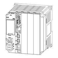
YASKAWA SVR32 User Manual (623 pages)
MP3000 Series Machine Controller, Motion Control
Brand:
YASKAWA
| Category:
Controller
| Size: 9.79 MB
Table of Contents
Table of Contents
22
Basic Information on
22
Machine-Specific
24
Making Settings for Motion
26
Stepping Motor Drive Operation
27
Basic Information on Motion Control
29
Types of Programs
30
Types of Motion Control
31
Position Control
31
Phase Control
32
Torque Control
32
Speed Control
32
Basic Information on Motion Control Function Modules
33
Overview
35
SVC Function Module
35
SVR Function Module
35
Conceptual Diagram
36
External Appearance and Indicators
37
Specifications
38
Motion Control Function Module Specifications
38
MECHATROLINK-III Communications Specifications for the SVC Function Module
39
SVC Function Module Specifications
40
SVR Function Module Specifications
42
Applicable Versions for Additional Functions
43
System Configuration Example
44
Topologies
46
Cascade Connections
46
Star Connections
47
Mixed Cascade/Star Connections
48
MECHATROLINK Transmission Cycle and the Number of Connected Slave Stations
49
Synchronization of the MECHATROLINK-III Transmission Cycle and High-Speed Scan Cycle
51
Synchronization Conditions
51
Timing at Which the MECHATROLINK Transmission Cycle and the High-Speed Scan Cycle Are Synchronized
51
Changing Synchronization Cycles
51
Reference Output Timing
52
Precautions When Combining with Other Modules
53
Parameters for Motion Control
54
Types of Motion Parameters
55
Motion Parameter Registers
56
Motion Parameter Tables
60
Fixed Parameter Table
60
Setting Parameter Table
63
Monitor Parameter Table
71
Motion Parameter Details
80
Fixed Parameter Details
80
Setting Parameter Details
89
Monitor Parameter Details
121
Automatically Updated Parameters
139
Automatically Updated Parameters When a MECHATROLINK Connection Is Established
139
Automatically Updated Parameters When a Setting Parameter Is Changed
141
Automatically Updated Parameters When a Motion Command Is Executed
142
3.5.4 Parameters Automatically Updated During Self Configuration
143
Motion Control Program Commands and Instructions
144
Commands
146
Motion Commands
146
Motion Subcommands
149
Motion Command Details
150
POSING (Positioning)
150
EX_POSING (External Positioning)
156
ZRET (Zero Point Return)
163
INTERPOLATE (Interpolation)
185
LATCH (Latch)
189
FEED (Jog)
193
STEP (STEP Operation)
198
ZSET (Set Zero Point)
203
ACC (Change Acceleration Time)
205
DCC (Change Deceleration Time)
207
SCC (Change Filter Time Constant)
209
CHG_FILTER (Change Filter Type)
211
KVS (Change Speed Loop Gain)
213
KPS (Change Position Loop Gain)
215
KFS (Change Feedforward)
217
PRM_RD (Read SERVOPACK Parameter)
219
PRM_WR (Write SERVOPACK Parameter)
221
ALM_MON (Monitor Alarms)
223
ALM_HIST (Monitor Alarm History)
225
ALMHIST_CLR (Clear Alarm History)
227
ABS_RST (Reset Absolute Encoder)
229
VELO (Issue Speed Reference)
232
TRQ (Issue Torque/Force Reference)
237
PHASE (Issue Phase Reference)
242
KIS (Change Position Loop Integral Time Constant)
246
PPRM_WR (Write Non-Volatile Parameter)
248
EX_FEED (Jog with External Positioning)
250
MEM_RD (Read Memory)
256
MEM_WR (Write Memory)
258
PMEM_RD (Read Non-Volatile Memory)
260
PMEM_WR (Write Non-Volatile Memory)
262
MLTTRN_SET (Multiturn Limit Setting)
264
Motion Subcommand Details
267
NOP (no Command)
267
PRM_RD (Read SERVOPACK Parameter)
268
PRM_WR (Write SERVOPACK Parameter)
270
INF_RD (Read Device Information)
272
SMON (Monitor Status)
274
FIXPRM_RD (Read Fixed Parameter)
276
FIXPRM_CHG (Change Fixed Parameter)
278
Changing the Command
280
Motion Command and Subcommand Execution Judgment Table
280
Operation after Changing the Motion Command
285
Motion Language Instructions
331
Machine-Specific Motion Control
342
Motion Parameters
344
Reference Unit
344
Electronic Gear
344
5.1.2 Electronic Gear
345
Axis Selection
346
Position References
347
Speed References
350
Acceleration/Deceleration Settings
352
Acceleration/Deceleration Filter Settings
355
Linear Scale Pitch and Rated Speed
356
Absolute Encoders
358
Absolute Position Detection
358
Absolute Encoder System Startup
359
Resetting the Absolute Encoder
361
Using the SERVOPACK to Reset the Absolute Encoder
365
Reading Position Data When the Power Supply Is Turned on
366
5.2.6 Position Management Method for each Machine Operation Type
367
Multiturn Limit
388
Check Items before Setup
388
Setting Procedure
388
Programming Example
390
Related Parameters
392
Multiturn Limit Setting Disagreement Detection Timing
392
Checking for a Multiturn Limit Setting Disagreement
392
Clearing the Warning
393
Absolute Encoders with 24-Bit Resolution
394
Encoder with 24-Bit Resolution and Electronic Gear Ratio Settings
394
Self Configuration and Encoder Resolution
395
Possible Travel Distances and Deceleration Times for the MP3000
396
Controlling Vertical Axes
400
SERVOPACK Holding Brake
400
Connecting to a Σ-V or Σ-7 Servo Drive
401
Overtravel
403
Overtravel Input Signal Connections
403
Parameter Settings
404
Software Limits
406
Software Limit Parameter Selection
406
Related Parameters
407
Comparison with the MP2000-Series SVC-01 Module
407
The Effects of Software Limits
408
Processing after an Alarm Occurs
408
Modal Latching
409
Latch Request
409
Canceling a Latch Request
409
Latch Signals
409
Related Parameters
409
6.4.4 Related Parameters
410
Waiting for Slave Detection with the SVC Function Module
411
Overview
411
Applicable Versions
411
Operating Procedure
412
Timing to Complete Slave Detection
413
Indicators When the Power Is Turned on
414
Precautions
414
Slave CPU Synchronization
415
Overview
415
Applicable Versions and Execution Conditions
416
Setting Procedure
417
I/O Registers
421
Execution Flow for Slave CPU Synchronization
422
Procedure to Turn on Power
423
Confirmation that the Slave CPU Is Synchronized
423
Handling Input Errors
424
Effect on Application Program
425
Operation of Slave MP3000
426
6.6.11 Precautions
427
Multiturn Limit Setting Disagreement Detection
428
Applicable Versions
428
Related Parameters
429
Multiturn Limit Setting Disagreement Detection Timing
429
Checking for a Multiturn Limit Setting Disagreement
429
Clearing the Warning
429
6.7.5 Clearing the Warning
430
Precautions When Using Σ-7-Series Servopacks
431
6.8.1 MP3000 Versions that Support the Σ-7-Series Servopacks
431
Σ-7-Series SERVOPACK Electronic Gear Ratio and MP3000 Settings
432
Link Assignments
433
Number of Pulses Per Motor Rotation
433
Self Configuration
433
6.8.6 Operating Specifications When Using an MP3000 Controller that Supports the Σ-7-Series Servopacks
434
Operating Specifications When Using an MP3000 Controller that Does Not Support the Σ-7-Series Servopacks
436
Making Settings for Motion Control with the MPE720
437
Module Configuration Settings
438
Settings for Motion Control Function Modules
438
Deleting Unused Motion Control Function Modules
441
MECHATROLINK Communications Settings
443
Displaying the MECHATROLINK Detail Definition Dialog Box
443
MECHATROLINK Detail Definition Dialog Box Details
444
Setting Motion Parameters
455
Displaying and Setting Motion Parameters
455
Precautions after Making Settings
458
SERVOPACK Parameter Data Flow
459
When the Power Supply Is Turned on
459
Normal Operation
460
When the SERVOPACK Tab Page Is Opened
460
When SERVOPACK Parameters Are Saved
461
When Saving Data to Flash Memory
461
One Axis Positioning
463
Machine Configuration
463
Related Parameters
463
Sample Programming
464
Interpolation of Two Axes
467
Machine Configuration
467
Related Parameters
468
Sample Programming
469
Torque Control
471
Machine Configuration
471
Related Parameters
471
Sample Programming
472
Phase Control
473
Machine Configuration
473
Related Parameters
474
Sample Programming
475
Overview
478
Connection Specifications
479
Parameter Support Table
480
Fixed Parameter Table
480
Setting Parameter Table
483
Monitor Parameter Table
492
Link Assignments
501
Common Parameters
502
Connection Specifications
504
Setup Procedure
505
Check Items before Setup
505
10.2.2 Inverter Settings
506
10.2.3 I/O Options
514
10.2.3 I/O Options
515
Precautions for Inverter Operation
516
Main Commands and Subcommands
521
List of Main Commands and Subcommands
521
Applicable Combinations of Main Commands and Subcommands
522
Main Command Details
523
10.4.4 Subcommand Details
530
Motion Parameter Details
537
Fixed Parameter List
537
10.5.2 Setting Parameter List
538
10.5.3 Monitor Parameter List
550
Inverter Output Data Details
561
10.5.5 Inverter Input Data Details
562
Alarm and Warning Codes for Inverter
566
10.6.1 A1000
566
10.6.2 V1000
570
10.6.2 V1000
572
Appendices
574
Appendices Provides Supplemental Information Related to Motion Control
574
Control Block Diagrams
575
11.1.1 Control Block Diagram for Position Control
575
11.1.2 Control Block Diagram for Phase Control
577
11.1.3 Control Block Diagram for Torque Control
579
11.1.4 Control Block Diagram for Speed Control
581
System Registers
583
11.2.1 System Service Registers
583
11.2.2 Scan Execution Status and Calendar
585
System Program Software Numbers and Remaining Program Memory Capacity
585
MECHATROLINK-III I/O Module Settings
586
Link Assignment Tab
586
11.3.2 I/O Register Configuration
587
I/O Commands
588
11.3.4 I/O Command Details
589
11.3.5 Command Control
605
11.3.6 Master Status
605
Command Status
606
CPU STOP Operation
608
Setting Fixed Parameters According to Encoder Type and Axis Type
609
Common Parameters and SERVOPACK Parameters
611
Terminology
613
Index
622
Revision History
622
Advertisement
Advertisement
Related Products
YASKAWA SVC
YASKAWA SVR
YASKAWA SVC32
YASKAWA SVA-01
YASKAWA SGD7S series
YASKAWA SMG Series
YASKAWA SGD7S-****00A Series
YASKAWA SI-EM3
YASKAWA SI-ES3/V
YASKAWA Sigma II Series
YASKAWA Categories
Controller
DC Drives
Servo Drives
Robotics
Inverter
More YASKAWA Manuals
Login
Sign In
OR
Sign in with Facebook
Sign in with Google
Upload manual
Upload from disk
Upload from URL