YASKAWA SGD7S series Product Manual
Sigma-7-series ac servo drive.
sigma-7s servopack with
analog voltage/pulse train references
Hide thumbs
Also See for SGD7S series:
- Product manual (621 pages) ,
- Selection manual (337 pages) ,
- Product manual (285 pages)
Table of Contents
Advertisement
Quick Links
-7-Series AC Servo Drive
-7S SERVOPACK with
Analog Voltage/Pulse Train References
Product Manual
Model: SGD7S-00A
MANUAL NO. SIEP S800001 26I
Basic Information on
SERVOPACKs
Selecting a SERVOPACK
SERVOPACK Installation
Wiring and Connecting
SERVOPACKs
Basic Functions That Require
Setting before Operation
Application Functions
Trial Operation and
Actual Operation
Tuning
Monitoring
Fully-Closed Loop Control
Safety Functions
Maintenance
Panel Displays and
Panel Operator Procedures
Parameter Lists
Appendices
1
2
3
4
5
6
7
8
9
10
11
12
13
14
15
Advertisement
Table of Contents
Troubleshooting

Related Manuals for YASKAWA SGD7S series


Summary of Contents for YASKAWA SGD7S series
- Page 1 -7-Series AC Servo Drive -7S SERVOPACK with Analog Voltage/Pulse Train References Product Manual Model: SGD7S-00A Basic Information on SERVOPACKs Selecting a SERVOPACK SERVOPACK Installation Wiring and Connecting SERVOPACKs Basic Functions That Require Setting before Operation Application Functions Trial Operation and Actual Operation Tuning Monitoring...
- Page 2 Yaskawa. No patent liability is assumed with respect to the use of the informa- tion contained herein. Moreover, because Yaskawa is constantly striving to improve its high-quality products, the information contained in this manual is sub- ject to change without notice.
- Page 3 About this Manual This manual provides information required to select Σ-7S SERVOPACKs with Analog Voltage/Pulse Train References for Σ-7-Series AC Servo Drives, and to design, perform trial operation of, tune, operate, and maintain the Servo Drives. Read and understand this manual to ensure correct usage of the Σ-7-Series AC Servo Drives. Keep this manual in a safe place so that it can be referred to whenever necessary.
- Page 4 Related Documents The relationships between the documents that are related to the Servo Drives are shown in the following figure. The numbers in the figure correspond to the numbers in the table on the following pages. Refer to these documents as required. y tem Component Machine Controller...
- Page 5 Classification Document Name Document No. Description Describes the features and applica- Machine Controller and tion examples for combinations of Machine Controller and AC Servo Drive KAEP S800001 22 MP3000-Series Machine Control- Servo Drive lers and Σ-7-Series AC Servo Solutions Catalog General Catalog Drives.
- Page 6 Continued from previous page. Classification Document Name Document No. Description Σ-7-Series AC Servo Drive Provides detailed information for Σ-7S and Σ-7W SERVOPACK the safe usage of Σ-7-Series TOMP C710828 00 Safety Precautions SERVOPACKs. Σ-V-Series/Σ-V-Series for Large-Capacity Models/ Provides detailed information for Σ-7-Series TOBP C720829 00 the safe usage of Option Modules.
- Page 7 Continued from previous page. Classification Document Name Document No. Description Σ-7-Series AC Servo Drive Σ-7S SERVOPACK with MECHATROLINK-III SIEP S800001 28 Communications References Product Manual Σ-7-Series AC Servo Drive Σ-7S SERVOPACK with MECHATROLINK-II SIEP S800001 27 Communications References Product Manual Σ-7-Series AC Servo Drive Σ-7S SERVOPACK with This manual...
- Page 8 Continued from previous page. Classification Document Name Document No. Description Σ-7-Series AC Servo Drive Σ-7S SERVOPACK with FT/EX Specification for Index- SIEP S800001 84 ing Application Product Manual Σ-7-Series AC Servo Drive Σ-7S SERVOPACK with FT/EX Specification for Track- SIEP S800001 89 ing Application Product Manual Σ-7-Series...
- Page 9 Continued from previous page. Classification Document Name Document No. Description Σ-7-Series AC Servo Drive Provides detailed information on MECHATROLINK-II the MECHATROLINK-II communi- SIEP S800001 30 Communications cations commands that are used for a Σ-7-Series Servo System. Command Manual Σ-7-Series MECHATROLINK Σ-7-Series AC Servo Drive Communications Provides detailed information on...
- Page 10 Using This Manual Technical Terms Used in This Manual The following terms are used in this manual. Term Meaning A Σ-7-Series Rotary Servomotor, Direct Drive Servomotor, or Linear Servomotor. Servomotor A generic term used for a Σ-7-Series Rotary Servomotor (SGMMV, SGM7J, SGM7A, SGM7P, Rotary Servomotor or SGM7G) or a Direct Drive Servomotor (SGM7E, SGM7F, SGMCV, or SGMCS).
- Page 11 Notation Used in this Manual Notation for Reverse Signals The names of reverse signals (i.e., ones that are valid when low) are written with a forward slash (/) before the signal abbreviation. Notation Example BK is written as /BK. ...
- Page 12 Trademarks • QR code is a trademark of Denso Wave Inc. • Other product names and company names are the trademarks or registered trademarks of the respective company. “TM” and the ® mark do not appear with product or company names in this manual.
- Page 13 Safety Precautions Safety Information To prevent personal injury and equipment damage in advance, the following signal words are used to indicate safety precautions in this document. The signal words are used to classify the hazards and the degree of damage or injury that may occur if a product is used incorrectly. Information marked as shown below is important for safety.
- Page 14 Safety Precautions That Must Always Be Observed General Precautions DANGER Read and understand this manual to ensure the safe usage of the product. Keep this manual in a safe, convenient place so that it can be referred to whenever necessary. Make sure that it is delivered to the final user of the product.
- Page 15 NOTICE Do not attempt to use a SERVOPACK or Servomotor that is damaged or that has missing parts. Install external emergency stop circuits that shut OFF the power supply and stops operation immediately when an error occurs. In locations with poor power supply conditions, install the necessary protective devices (such as AC reactors) to ensure that the input power is supplied within the specified voltage range.
- Page 16 NOTICE Do not hold onto the front cover or connectors when you move a SERVOPACK. There is a risk of the SERVOPACK falling. A SERVOPACK or Servomotor is a precision device. Do not drop it or subject it to strong shock. There is a risk of failure or damage.
- Page 17 NOTICE Do not install or store the product in any of the following locations. • Locations that are subject to direct sunlight • Locations that are subject to ambient temperatures that exceed product specifications • Locations that are subject to relative humidities that exceed product specifications •...
- Page 18 Whenever possible, use the Cables specified by Yaskawa. If you use any other cables, confirm the rated current and application environment of your model and use the wiring materials specified by Yaskawa or equivalent materials. Securely tighten cable connector screws and lock mechanisms.
- Page 19 Operation Precautions WARNING Before starting operation with a machine connected, change the settings of the switches and parameters to match the machine. Unexpected machine operation, failure, or personal injury may occur if operation is started before appropriate settings are made. ...
- Page 20 NOTICE When you adjust the gain during system commissioning, use a measuring instrument to monitor the torque waveform and speed waveform and confirm that there is no vibration. If a high gain causes vibration, the Servomotor will be damaged quickly. ...
- Page 21 Troubleshooting Precautions DANGER If the safety device (molded-case circuit breaker or fuse) installed in the power supply line oper- ates, remove the cause before you supply power to the SERVOPACK again. If necessary, repair or replace the SERVOPACK, check the wiring, and remove the factor that caused the safety device to operate.
- Page 22 We will update the manual number of the manual and issue revisions when changes are made. Any and all quality guarantees provided by Yaskawa are null and void if the customer modifies the product in any way. Yaskawa disavows any responsibility for damages or losses that are caused by modified products.
- Page 23 • Events for which Yaskawa is not responsible, such as natural or human-made disasters Limitations of Liability • Yaskawa shall in no event be responsible for any damage or loss of opportunity to the customer that arises due to failure of the delivered product.
- Page 24 • It is the customer’s responsibility to confirm conformity with any standards, codes, or regulations that apply if the Yaskawa product is used in combination with any other products. • The customer must confirm that the Yaskawa product is suitable for the systems, machines, and equipment used by the customer.
- Page 25 Compliance with UL Standards, EU Directives, and Other Safety Standards Certification marks for the standards for which the product has been certified by certification bodies are shown on nameplate. Products that do not have the marks are not certified for the standards. ...
- Page 26 European Directives Product Model EU Directive Harmonized Standards Machinery Directive EN ISO13849-1: 2015 2006/42/EC EN 55011 group 1, class A EMC Directive EN 61000-6-2 SERVOPACKs SGD7S 2004/108/EC EN 61000-6-4 EN 61800-3 Low Voltage Directive EN 50178 2006/95/EC EN 61800-5-1 EN 55011 group 1, class A EMC Directive EN 61000-6-2...
- Page 27 Safety Parameters Item Standards Performance Level IEC 61508 SIL3 Safety Integrity Level IEC 62061 SILCL3 IEC 61508 PFH = 4.04×10 [1/h] Probability of Dangerous Failure per Hour IEC 62061 (4.04% of SIL3) Performance Level EN ISO 13849-1 PLe (Category 3) Mean Time to Dangerous Failure of Each Channel EN ISO 13849-1 MTTFd: High Average Diagnostic Coverage...
-
Page 28: Table Of Contents
Contents About this Manual ..........iii Outline of Manual . - Page 29 Examples of Standard Connections between SERVOPACKs and Peripheral Devices . . 2-26 SERVOPACK Installation Installation Precautions ....... 3-2 Mounting Types and Orientation .
- Page 30 Connecting the Other Connectors ..... . 4-50 4.7.1 Serial Communications Connector (CN3) ......4-50 4.7.2 Computer Connector (CN7) .
- Page 31 5.13 Holding Brake ........5-36 5.13.1 Brake Operating Sequence .
- Page 32 Position Control ........6-30 6.6.1 Basic Settings for Position Control .
- Page 33 6.14 Software Reset ........6-96 6.14.1 Preparations .
- Page 34 Tuning Overview and Flow of Tuning ......8-4 8.1.1 Tuning Functions ..........8-5 8.1.2 Diagnostic Tool .
- Page 35 Anti-Resonance Control Adjustment ....8-51 8.9.1 Outline........... . 8-51 8.9.2 Preparations .
- Page 36 Monitoring Product Life ......9-15 9.4.1 Items That You Can Monitor ........9-15 9.4.2 Operating Procedure .
- Page 37 11.5 Validating Safety Functions ......11-11 11.6 Connecting a Safety Function Device ....11-12 Maintenance 12.1 Inspections and Part Replacement .
- Page 38 13.4 Utility Function (Fn) Operations on the Panel Operator . . .13-12 13.4.1 Display Alarm History (Fn000)........13-12 13.4.2 Jog (Fn002) .
- Page 39 Appendices 15.1 Examples of Connections to Host Controllers ... . 15-2 15.1.1 Example of Connections to MP2000/MP3000-Series SVA-01 Motion Module..........15-2 15.1.2 Example of Connections to Yokogawa Electric’s F3YP2-0P Positioning Module for Position Control .
- Page 40 Basic Information on SERVOPACKs This chapter provides information required to select SERVOPACKs, such as SERVOPACK models and combi- nations with Servomotors. The Σ-7 Series ..... . . 1-2 Interpreting the Nameplate .
-
Page 41: The Σ-7 Series
1.1 The Σ-7 Series Σ -7 Series The Σ-7-series SERVOPACKs are designed for applications that require frequent high-speed and high-precision positioning. The SERVOPACK will make the most of machine performance in the shortest time possible, thus contributing to improving productivity. The Σ-7-series SERVOPACKs include Σ-7S SERVOPACKs for single-axis control and Σ-7W SERVOPACKs for two-axis control. -
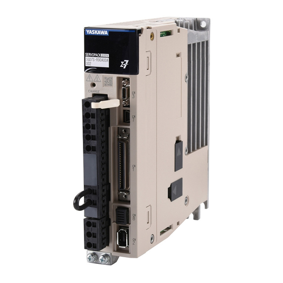
Page 42: Interpreting The Nameplate
1.2 Interpreting the Nameplate Interpreting the Nameplate The following basic information is provided on the nameplate. ERVOPACK model Degree of protection urrounding air temperature BTO information Order number erial number... -
Page 43: Part Names
1.3 Part Names Part Names With Front Cover Open (on ide of ERVOPACK) Main circuit terminal Motor terminal Name Description Reference − − Front Cover Nameplate Indicates the SERVOPACK model and ratings. page 1-3 − Input Voltage –... - Page 44 1.3 Part Names Continued from previous page. Name Description Reference Used to display SERVOPACK status, alarm numbers, and Panel Display parameters. page 13-3 Panel Operator Keys Used to set parameters. − Panel Operator Analog Monitor Connector You can use a special cable (peripheral device) to monitor page 4-50 (CN5) the motor speed, torque reference, or other values.
-
Page 45: Model Designations
1.4 Model Designations 1.4.1 Interpreting SERVOPACK Model Numbers Model Designations 1.4.1 Interpreting SERVOPACK Model Numbers - R70 14th 5th+6th 1 t+2nd+ rd 8th+9th+10th 11th+12th+1 th Σ-7- erie digit digit digit digit digit digit digit Σ-7 ERVOPACK Maximum Applicable Hardware Option 1 t+2nd+ rd digit 4th digit 8th+9th+10th digit... -
Page 46: Interpreting Servomotor Model Numbers
1.4 Model Designations 1.4.2 Interpreting Servomotor Model Numbers 1.4.2 Interpreting Servomotor Model Numbers This section outlines the model numbers of Σ-7-series Servomotors. Refer to the relevant man- ual in the following list for details. Σ-7-Series Rotary Servomotor Product Manual (Manual No.: SIEP S800001 36) Σ-7-Series Linear Servomotor Product Manual (Manual No.: SIEP S800001 37) Σ-7-Series Direct Drive Servomotor Product Manual (Manual No.: SIEP S800001 38) Rotary Servomotors... -
Page 47: Combinations Of Servopacks And Servomotors
1.5 Combinations of SERVOPACKs and Servomotors 1.5.1 Combinations of Rotary Servomotors and SERVOPACKs Combinations of SERVOPACKs and Servomotors 1.5.1 Combinations of Rotary Servomotors and SERVOPACKs SERVOPACK Model Rotary Servomotor Model Capacity SGD7S- SGMMV Models SGMMV-A1A 10 W R90A or R90F (Low Inertia, Ultra- SGMMV-A2A 20 W... -
Page 48: Combinations Of Direct Drive Servomotors And Servopacks
1.5 Combinations of SERVOPACKs and Servomotors 1.5.2 Combinations of Direct Drive Servomotors and SERVOPACKs 1.5.2 Combinations of Direct Drive Servomotors and SERVOPACKs Instantaneous SERVOPACK Model Rated Torque Direct Drive Servomotor Model Maximum Torque [N·m] SGD7S- [N·m] SGM7E-02B SGM7E-05B 2R8A or 2R1F SGM7E-07B SGM7E-04C SGM7E Models... -
Page 49: Combinations Of Linear Servomotors And Servopacks
1.5 Combinations of SERVOPACKs and Servomotors 1.5.3 Combinations of Linear Servomotors and SERVOPACKs 1.5.3 Combinations of Linear Servomotors and SERVOPACKs Instantaneous SERVOPACK Model Rated Torque Linear Servomotor Model Maximum Torque SGD7S- SGLGW-30A050C 12.5 R70A or R70F SGLGW-30A080C R90A or R90F SGLGW-40A140C SGLGW-40A253C 1R6A or 2R1F... -
Page 50: Combinations Of Linear Servomotors And Servopacks
1.5 Combinations of SERVOPACKs and Servomotors 1.5.3 Combinations of Linear Servomotors and SERVOPACKs Continued from previous page. Instantaneous SERVOPACK Model Rated Torque Linear Servomotor Model Maximum Torque SGD7S- SGLTW-20A170A 3R8A SGLTW-20A320A 7R6A SGLTW-20A460A 1140 120A SGLTW-35A170A 5R5A SGLTW-35A170H SGLTW-35A320A 1320 120A SGLT Models SGLTW-35A320H... -
Page 51: Functions
1.6 Functions Functions This section lists the functions provided by SERVOPACKs. Refer to the reference pages for details on the functions. • Functions Related to the Machine Function Reference Power Supply Type Settings for the Main Circuit page 5-14 and Control Circuit Automatic Detection of Connected Motor page 5-16 Motor Direction Setting... - Page 52 1.6 Functions • Functions Related to the Host Controller Function Reference Electronic Gear Settings page 5-46 I/O Signal Allocations page 6-5 Servo Alarm (ALM) Signal page 6-10 Alarm Code (ALO1 to ALO3) Signals page 6-10 Warning Output (/WARN) Signal page 6-11 Rotation Detection (/TGON) Signal page 6-11 /S-RDY (Servo Ready) Signal...
- Page 53 1.6 Functions • Functions to Achieve Optimum Motions Function Reference Speed Control page 6-17 Soft Start Settings page 6-24 Position Control page 6-30 Smoothing Settings page 6-36 Torque Control page 6-40 Tuning-less Function page 8-12 Automatic Adjustment without a Host Reference page 8-24 Automatic Adjustment with a Host Reference page 8-35...
-
Page 54: Selecting A Servopack
Selecting a SERVOPACK This chapter provides information required to select SERVOPACKs, such as specifications, block diagrams, dimensional drawings, and connection examples. Ratings and Specifications ... . . 2-2 2.1.1 Ratings ....... . 2-2 2.1.2 SERVOPACK Overload Protection Characteristics . -
Page 55: Ratings And Specifications
2.1 Ratings and Specifications 2.1.1 Ratings Ratings and Specifications This section gives the ratings and specifications of SERVOPACKs. 2.1.1 Ratings Three-Phase, 200 VAC Model SGD7S- R70A R90A 1R6A 2R8A 3R8A 5R5A 7R6A 120A 180A 200A 330A Maximum Applicable Motor Capac- 0.05 0.75 ity [kW]... - Page 56 2.1 Ratings and Specifications 2.1.1 Ratings Model SGD7S- 470A 550A 590A 780A Maximum Applicable Motor Capacity [kW] Continuous Output Current [Arms] 46.9 54.7 58.6 78.0 Instantaneous Maximum Output Current [Arms] Power Supply 200 VAC to 240 VAC, -15% to +10%, 50 Hz/60 Hz Main Circuit Input Current [Arms] Power Supply...
- Page 57 2.1 Ratings and Specifications 2.1.1 Ratings 270 VDC Model SGD7S- R70A R90A 1R6A 2R8A 3R8A 5R5A 7R6A 120A Maximum Applicable Motor Capacity [kW] 0.05 0.75 Continuous Output Current [Arms] 0.66 0.91 11.6 Instantaneous Maximum Output Current [Arms] 11.0 16.9 17.0 28.0 Power Supply 270 VDC to 324 VDC, -15% to +10%...
-
Page 58: Servopack Overload Protection Characteristics
Note: The above overload protection characteristics do not mean that you can perform continuous duty operation with an output of 100% or higher. For a Yaskawa-specified combination of SERVOPACK and Servomotor, maintain the effective torque within the continuous duty zone of the torque-motor speed characteristic of the Servomotor. -
Page 59: Specifications
2.1 Ratings and Specifications 2.1.3 Specifications 2.1.3 Specifications Item Specification Control Method IGBT-based PWM control, sine wave current drive Serial encoder: 17 bits (absolute encoder) 20 bits or 24 bits (incremental encoder/absolute With Rotary Servomotor encoder) 22 bits (absolute encoder) Feedback •... - Page 60 2.1 Ratings and Specifications 2.1.3 Specifications Continued from previous page. Item Specification 1:5000 (At the rated torque, the lower limit of the speed control range Speed Control Range must not cause the Servomotor to stop.) ±0.01% of rated speed max. (for a load fluctuation of 0% to 100%) 0% of rated speed max.
- Page 61 2.1 Ratings and Specifications 2.1.3 Specifications Continued from previous page. Item Specification Allowable voltage range: 5 VDC to 30 VDC Fixed Number of output points: 1 Output Output signal: ALM (Servo Alarm) signal Allowable voltage range: 5 VDC to 30 VDC Number of output points: 6 (A photocoupler output (isolated) is used for three of the outputs.) (An open-collector output (non-isolated) is used for the other three out-...
- Page 62 2.1 Ratings and Specifications 2.1.3 Specifications Continued from previous page. Item Specification Inputs /HWBB1 and /HWBB2: Base block signals for Power Modules Output EDM1: Monitors the status of built-in safety circuit (fixed output). Safety Functions Applicable Stan- ISO13849-1 PLe (Category 3) and IEC61508 SIL3 dards Fully-closed Modules and Safety Modules Applicable Option Modules...
- Page 63 2.1 Ratings and Specifications 2.1.3 Specifications If you combine a Σ-7-Series SERVOPACK with a Σ-V-Series Option Module, the following Σ-V-Series SERVO- PACKs specifications must be used: a surrounding air temperature of 0°C to 55°C and an altitude of 1,000 m max.
-
Page 64: Block Diagrams
2.2 Block Diagrams 2.2.1 SGD7S-R70A, -R90A, and -1R6A Block Diagrams 2.2.1 SGD7S-R70A, -R90A, and -1R6A ervomotor Vari tor Main circuit power − upply Dynamic brake circuit Voltage Relay Voltage Temperature Gate drive Current Gate drive en or drive en or en or overcurrent protection en or... -
Page 65: Sgd7S-3R8A, -5R5A, And -7R6A
2.2 Block Diagrams 2.2.3 SGD7S-3R8A, -5R5A, and -7R6A 2.2.3 SGD7S-3R8A, -5R5A, and -7R6A ervomotor Vari tor Main circuit − power upply Dynamic brake circuit Voltage Relay Temperature Gate drive Current Voltage Gate drive en or drive en or overcurrent protection en or en or Vari tor... -
Page 66: Sgd7S-120A
2.2 Block Diagrams 2.2.4 SGD7S-120A 2.2.4 SGD7S-120A • Standard Specifications: Three-Phase, 200-VAC Power Supply Input ervomotor Vari tor Main circuit − power upply Overheat/ Dynamic overcurrent brake circuit protection Relay Current Voltage Voltage Temperature Gate drive Gate drive drive en or en or en or en or... -
Page 67: Sgd7S-180A And -200A
2.2 Block Diagrams 2.2.5 SGD7S-180A and -200A 2.2.5 SGD7S-180A and -200A ervomotor Vari tor Main circuit − power upply Overheat/overcurrent Dynamic protection brake circuit Relay Voltage Temperature Current Voltage Gate drive en or en or en or drive en or Vari tor Control Analog... -
Page 68: Sgd7S-330A
2.2 Block Diagrams 2.2.6 SGD7S-330A 2.2.6 SGD7S-330A Fan 1 Fan 2 ervomotor Vari tor Main circuit − power upply Overheat/overcurrent Dynamic protection brake circuit Voltage Thyri tor en or drive Voltage Temperature Current Gate drive en or en or en or Vari tor Control Analog... -
Page 69: Sgd7S-470A And -550A
2.2 Block Diagrams 2.2.7 SGD7S-470A and -550A 2.2.7 SGD7S-470A and -550A Fan 1 Fan 2 ervomotor Vari tor Main circuit − power upply Overheat/overcurrent Dynamic protection brake circuit Voltage Thyri tor drive en or Voltage Temperature Current Gate drive en or en or en or Vari tor... -
Page 70: Sgd7S-590A And -780A
2.2 Block Diagrams 2.2.8 SGD7S-590A and -780A 2.2.8 SGD7S-590A and -780A Fan 1 Fan 2 Fan 4 ervomotor Vari tor Main circuit − power upply Overheat/overcurrent Dynamic protection brake circuit Voltage Thyri tor en or drive Voltage Temperature Current Gate drive en or en or en or... -
Page 71: Sgd7S-2R8F
2.2 Block Diagrams 2.2.10 SGD7S-2R8F 2.2.10 SGD7S-2R8F ervomotor Vari tor Main − circuit power − upply Dynamic brake circuit Current Gate drive Voltage Relay Voltage Gate Temperature overcurrent en or en or drive en or drive en or protection Vari tor Analog Analog monitor Control... -
Page 72: External Dimensions
2.3 External Dimensions 2.3.1 Front Cover Dimensions and Connector Specifications External Dimensions 2.3.1 Front Cover Dimensions and Connector Specifications The front cover dimensions and panel connector section are the same for all models. Refer to the following figures and table. •... -
Page 73: Servopack External Dimensions
2.3 External Dimensions 2.3.2 SERVOPACK External Dimensions 2.3.2 SERVOPACK External Dimensions Base-mounted SERVOPACKs • Three-phase, 200 VAC: SGD7S-R70A, -R90A, and -1R6A 2×M4 Exterior 10 ±0.5 (mounting pitch) Ground terminal 2 × M4 (75) Mounting Hole Diagram Approx. ma : 0.8 kg Unit: mm •... - Page 74 2.3 External Dimensions 2.3.2 SERVOPACK External Dimensions • Three-phase, 200 VAC: SGD7S-120A 80 ±0.5 (mounting pitch) ×M4 Exterior 12.5 Ground terminal (75) 2 × M4 Mounting Hole Diagram Approx. ma : 2.2 kg Unit: mm • Three-phase, 200 VAC: SGD7S-180A and -200A; Single-phase, 200 VAC: SGD7S-120A00A008 ×M4 Exterior Terminal...
- Page 75 2.3 External Dimensions 2.3.2 SERVOPACK External Dimensions • Three-phase, 200 VAC: SGD7S-470A and -550A 4×M6 Exterior Terminal 4×M5 Terminal 8×M5 Ground 142 ± 0.5 (mounting pitch) terminal 2×M5 (75) Mounting Hole Diagram Approx. Ma : 8.2 kg Unit: mm • Three-phase, 200 VAC: SGD7S-590A and -780A 4×M6 Exterior Terminal...
- Page 76 2.3 External Dimensions 2.3.2 SERVOPACK External Dimensions Rack-mounted SERVOPACKs Hardware Option Code: 001 • Three-phase, 200 VAC: SGD7S-R70A, -R90A, and -1R6A 2 × M4 Exterior Ground (25) 24.5 terminal 2 × M4 (75) Mounting Hole Diagram Approx. ma : 0.8 kg Unit: mm •...
- Page 77 2.3 External Dimensions 2.3.2 SERVOPACK External Dimensions • Three-phase, 200 VAC: SGD7S-120A 15.5 × Exterior 50±0.5 (25) 24.5 (mounting pitch) Ground (75) terminal × Mounting Hole Diagram Approx. ma : 2.2 kg Unit: mm • Three-phase, 200 VAC: SGD7S-180A and -200A 20.5 ×...
- Page 78 2.3 External Dimensions 2.3.2 SERVOPACK External Dimensions Duct-ventilated SERVOPACKs Hardware Option Code: 001 • Three-phase, 200 VAC: SGD7S-470A and -550A × Exterior Cutout Terminal 4 × M5 Terminal ± 8 × M5 (71) Ground (mounting pitch) (75) terminal 162 min 2 ×...
-
Page 79: Examples Of Standard Connections Between Servopacks And Peripheral Devices
External Regenerative Resistors are not provided by Yaskawa. The power supply for the holding brake is not provided by Yaskawa. Select a power supply based on the hold- ing brake specifications. If you use a 24-V brake, install a separate power supply for the 24-VDC power supply from other power sup- plies, such as the one for the I/O signals of the CN1 connector. - Page 80 Linear Encoder Cable Linear encoder Linear ervomotor This example is for a SERVOPACK with a three-phase, 200-VAC power supply input. The pin layout of the main circuit connector depends on the voltage. External Regenerative Resistors are not provided by Yaskawa. 2-27...
-
Page 81: Servopack Installation
SERVOPACK Installation This chapter provides information on installing SERVO- PACKs in the required locations. Installation Precautions ....3-2 Mounting Types and Orientation ..3-3 Mounting Hole Dimensions . -
Page 82: Installation Precautions
3.1 Installation Precautions Installation Precautions Refer to the following section for the ambient installation conditions. 2.1.3 Specifications on page 2-6 Installation Near Sources of Heat Implement measures to prevent temperature increases caused by radiant or convection heat from heat sources so that the ambient temperature of the SERVOPACK meets the ambient conditions. -
Page 83: Mounting Types And Orientation
3.2 Mounting Types and Orientation Mounting Types and Orientation The SERVOPACKs come in the following mounting types: base-mounted, rack-mounted, and duct-ventilated types. Regardless of the mounting type, mount the SERVOPACK vertically, as shown in the following figures. Also, mount the SERVOPACK so that the front panel is facing toward the operator. Note: Prepare two to four mounting holes for the SERVOPACK and mount it securely in the mounting holes. -
Page 84: Mounting Hole Dimensions
3.3 Mounting Hole Dimensions Mounting Hole Dimensions Use mounting holes to securely mount the SERVOPACK to the mounting surface. Note: To mount the SERVOPACK, you will need to prepare a screwdriver that is longer than the depth of the SERVOPACK. ... - Page 85 R90F, 2R1F 3R8A, 5R5A, − 150±0.5 58±0.5 7R6A, 2R8F SGD7S- − 120A 150±0.5 80±0.5 180A, 200A, − 170±0.5 90±0.5 120A008 330A 238.5±0.5 110 100±0.5 100±0.5 470A, 550A, A special attachment is required. Contact your Yaskawa representative for details. 590A, 780A...
-
Page 86: Mounting Interval
3.4 Mounting Interval 3.4.1 Installing One SERVOPACK in a Control Panel Mounting Interval 3.4.1 Installing One SERVOPACK in a Control Panel Provide the following spaces around the SERVOPACK. 40 mm min. 0 mm min. 0 mm min. 40 mm min.* For this dimension, ignore items protruding from the main body of the SERVOPACK. -
Page 87: Monitoring The Installation Environment
3.5 Monitoring the Installation Environment Monitoring the Installation Environment You can use the SERVOPACK Installation Environment Monitor parameter to check the operat- ing conditions of the SERVOPACK in the installation environment. You can check the SERVOPACK installation environment monitor with either of the following methods. -
Page 88: Derating Specifications
3.6 Derating Specifications Derating Specifications If you use the SERVOPACK at a surrounding air temperature of 55°C to 60°C or at an altitude of 1,000 m to 2,000 m, you must apply the derating rates given in the following graphs. •... -
Page 89: Emc Installation Conditions
The EMC installation conditions that are given here are the conditions that were used to pass testing criteria at Yaskawa. The EMC level may change under other conditions, such as the actual installation structure and wiring conditions. These Yaskawa products are designed to be built into equipment. - Page 90 3.7 EMC Installation Conditions • Single-Phase, 200 VAC hield box Brake power upply ERVOPACK Brake U, V, and W Power upply: Noi e L1 and L2 ingle-pha e, 200 VAC filter ervomotor L1C and L2C urge ab orber Encoder Clamp Clamp Clamp Ho t...
- Page 91 3.7 EMC Installation Conditions • Single-Phase, 100 VAC hield box Brake power upply ERVOPACK Brake U, V, and W Power upply: Noi e L1 and L2 ingle-pha e, 100 VAC filter ervomotor L1C and L2C urge ab orber Encoder Clamp Clamp Clamp Ho t...
-
Page 92: Wiring And Connecting Servopacks
Wiring and Connecting SERVOPACKs This chapter provides information on wiring and connecting SERVOPACKs to power supplies and peripheral devices. Wiring and Connecting SERVOPACKs ..4-3 4.1.1 General Precautions ..... . 4-3 4.1.2 Countermeasures against Noise . - Page 93 Connecting Safety Function Signals ..4-48 4.6.1 Pin Arrangement of Safety Function Signals (CN8) . . 4-48 4.6.2 I/O Circuits ......4-48 Connecting the Other Connectors .
-
Page 94: Wiring And Connecting Servopacks
4.1 Wiring and Connecting SERVOPACKs 4.1.1 General Precautions Wiring and Connecting SERVOPACKs 4.1.1 General Precautions DANGER Do not change any wiring while power is being supplied. There is a risk of electric shock or injury. WARNING Wiring and inspections must be performed only by qualified engineers. There is a risk of electric shock or product failure. - Page 95 Whenever possible, use the Cables specified by Yaskawa. If you use any other cables, confirm the rated current and application environment of your model and use the wiring materials specified by Yaskawa or equivalent materials. Securely tighten cable connector screws and lock mechanisms.
-
Page 96: Countermeasures Against Noise
To ensure safe, stable application of the servo system, observe the following precautions when wiring. • Use the cables specified by Yaskawa. Design and arrange the system so that each cable is as short as possible. Refer to the following manual for information on the specified cables. - Page 97 4.1 Wiring and Connecting SERVOPACKs 4.1.2 Countermeasures against Noise Noise Filters You must attach Noise Filters in appropriate places to protect the SERVOPACK from the adverse effects of noise. The following is an example of wiring for countermeasures against noise. ERVOPACK Noi e Filter ervomotor...
- Page 98 4.1 Wiring and Connecting SERVOPACKs 4.1.2 Countermeasures against Noise Noise Filter Wiring and Connection Precautions Always observe the following precautions when wiring or connecting Noise Filters. • Separate input lines from output lines. Do not place input lines and output lines in the same duct or bundle them together.
-
Page 99: Grounding
4.1 Wiring and Connecting SERVOPACKs 4.1.3 Grounding • If a Noise Filter is located inside a control panel, first connect the Noise Filter ground wire and the ground wires from other devices inside the control panel to the grounding plate for the control panel, then ground the plate. -
Page 100: Basic Wiring Diagrams
4.2 Basic Wiring Diagrams Basic Wiring Diagrams This section provide the basic wiring diagrams. Refer to the reference sections given in the diagrams for details. ERVOPACK Main circuit Motor terminal terminal 4.4 Wiring Ser- 1FLT vomotors on page 4-25 PG5V PG0V (For ervo alarm di play) - Page 101 You can enable this function with a parameter setting. The 24-VDC power supply is not provided by Yaskawa. Use a 24-VDC power supply with double insulation or reinforced insulation. Refer to the following chapter if you use a safety function device.
-
Page 102: Wiring The Power Supply To The Servopack
4.3 Wiring the Power Supply to the SERVOPACK 4.3.1 Terminal Symbols and Terminal Names Wiring the Power Supply to the SERVOPACK 4.3.1 Terminal Symbols and Terminal Names Use the main circuit connector on the SERVOPACK to wire the main circuit power supply and control circuit power supply to the SERVOPACK. - Page 103 4.3 Wiring the Power Supply to the SERVOPACK 4.3.1 Terminal Symbols and Terminal Names • Single-Phase, 200-VAC Power Supply Input Terminal Terminal Name Specifications and Reference Symbols Main circuit power supply Single-phase, 200 VDC to 240 VDC, -15% to +10%, 50 Hz/ L1, L2 input terminals for AC 60 Hz...
- Page 104 4.3 Wiring the Power Supply to the SERVOPACK 4.3.1 Terminal Symbols and Terminal Names • Single-Phase, 100-VAC Power Supply Input Terminal Terminal Name Specifications and Reference Symbols Main circuit power supply Single-phase, 100 VAC to 120 VAC, -15% to +10%, L1, L2 input terminals for AC 50 Hz/60 Hz...
-
Page 105: Wiring Procedure For Main Circuit Connector
4.3 Wiring the Power Supply to the SERVOPACK 4.3.2 Wiring Procedure for Main Circuit Connector 4.3.2 Wiring Procedure for Main Circuit Connector • Required Items Required Item Remarks • Spring Opener SERVOPACK accessory Spring Opener or Flat- (You can also use model 1981045-1 from Tyco Electronics Japan G.K.) blade Screwdriver •... -
Page 106: Power On Sequence
4.3 Wiring the Power Supply to the SERVOPACK 4.3.3 Power ON Sequence 4.3.3 Power ON Sequence Consider the following points when you design the power ON sequence. • The ALM (Servo Alarm) signal is output for up to five seconds when the control power supply is turned ON. -
Page 107: Power Supply Wiring Diagrams
4.3 Wiring the Power Supply to the SERVOPACK 4.3.4 Power Supply Wiring Diagrams 4.3.4 Power Supply Wiring Diagrams Using Only One SERVOPACK • Wiring Example for Three-Phase, 200-VAC Power Supply Input: SGD7S-R70A, -R90A, -1R6A, -2R8A, -3R8A, -5R5A, -7R6A, -120A, -180A,-200A, and -330A ERVOPACK 1FLT +24 V... - Page 108 4.3 Wiring the Power Supply to the SERVOPACK 4.3.4 Power Supply Wiring Diagrams • Wiring Example for Single-Phase, 200-VAC Power Supply Input ERVOPACK 1FLT +24 V (For ervo alarm di play) − ervo power ervo power 1QF: Molded-ca e circuit breaker 1Ry: Relay 1FLT: Noi e Filter 1PL: Indicator lamp...
- Page 109 4.3 Wiring the Power Supply to the SERVOPACK 4.3.4 Power Supply Wiring Diagrams • Wiring Example for DC Power Supply Input: SGD7S-R70A, -R90A, -1R6A, -2R8A, -3R8A, -5R5A, -7R6A, -120A, -180A, and -200A ERVOPACK 1FLT AC/DC AC/DC +24 V (For ervo alarm di play) ervo power ervo power...
- Page 110 4.3 Wiring the Power Supply to the SERVOPACK 4.3.4 Power Supply Wiring Diagrams • Wiring Example for DC Power Supply Input: SGD7S-330A, -470A, -550A, -590A, and -780A ERVOPACK 1FLT AC/DC 1TRy AC/DC +24 V (For ervo alarm di play) − ervo power ervo power +24 V...
- Page 111 4.3 Wiring the Power Supply to the SERVOPACK 4.3.4 Power Supply Wiring Diagrams • Wiring Example for Single-Phase, 100-VAC Power Supply Input: SGD7S-R70F, -R90F, -2R1F, or -2R8F ERVOPACK 1FLT +24 V (For ervo alarm di play) − ervo power ervo power 1Ry: Relay 1PL:...
- Page 112 4.3 Wiring the Power Supply to the SERVOPACK 4.3.4 Power Supply Wiring Diagrams Using More Than One SERVOPACK Connect the ALM (Servo Alarm) output for these SERVOPACKs in series to operate the alarm detection relay (1RY). When a SERVOPACK alarm is activated, the ALM output signal transistor turns OFF. The following diagram shows the wiring to stop all of the Servomotors when there is an alarm for any one SERVOPACK.
-
Page 113: Wiring Regenerative Resistors
4.3 Wiring the Power Supply to the SERVOPACK 4.3.5 Wiring Regenerative Resistors 4.3.5 Wiring Regenerative Resistors This section describes how to connect External Regenerative Resistors. Refer to the following manual to select External Regenerative Resistors. Σ-7-Series Peripheral Device Selection Manual (Manual No.: SIEP S800001 32) WARNING ... - Page 114 Set Pn600 (Regenerative Resistor Capacity) and Pn603 (Regenerative Resistance) as required. • When using the Yaskawa-recommended Regenerative Resistor Unit, use the default settings for Pn600 and Pn603. • If you use any other external regenerative resistor, set Pn600 and Pn603 according to the specifica- tions of the regenerative resistor.
-
Page 115: Wiring Reactors For Harmonic Suppression
4.3 Wiring the Power Supply to the SERVOPACK 4.3.6 Wiring Reactors for Harmonic Suppression 4.3.6 Wiring Reactors for Harmonic Suppression You can connect a reactor for harmonic suppression to the SERVOPACK when power supply harmonic suppression is required. Refer to the following manual for details on harmonic reac- tors. -
Page 116: Wiring Servomotors
4.4 Wiring Servomotors 4.4.1 Terminal Symbols and Terminal Names Wiring Servomotors 4.4.1 Terminal Symbols and Terminal Names The SERVOPACK terminals or connectors that are required to connect the SERVOPACK to a Servomotor are given below. Terminal/Connector Terminal/Connector Name Remarks Symbols Refer to the following section for the wiring proce- dure. -
Page 117: Wiring The Servopack To The Encoder
4.4 Wiring Servomotors 4.4.3 Wiring the SERVOPACK to the Encoder 4.4.3 Wiring the SERVOPACK to the Encoder When Using an Absolute Encoder If you use an absolute encoder, use an Encoder Cable with a JUSP-BA01-E Battery Case or install a battery on the host controller. Refer to the following section for the battery replacement procedure. -
Page 118: Wiring The Servopack To The Encoder
4.4 Wiring Servomotors 4.4.3 Wiring the SERVOPACK to the Encoder • When Installing a Battery on the Encoder Cable Use the Encoder Cable with a Battery Case that is specified by Yaskawa. Refer to the following manual for details. Σ... - Page 119 4.4 Wiring Servomotors 4.4.3 Wiring the SERVOPACK to the Encoder When Using an Absolute Linear Encoder The wiring depends on the manufacturer of the linear encoder. Connections to Linear Encoder from Heidenhain Corporation Linear encoder from Interface Unit from Heidenhain Corporation Cable from ERVOPACK...
- Page 120 4.4 Wiring Servomotors 4.4.3 Wiring the SERVOPACK to the Encoder When Using an Incremental Linear Encoder The wiring depends on the manufacturer of the linear encoder. Connections to Linear Encoder from Heidenhain Corporation Linear encoder from Heidenhain Corporation erial Converter Unit ERVOPACK / IN /REF...
- Page 121 4.4 Wiring Servomotors 4.4.3 Wiring the SERVOPACK to the Encoder Connections to Linear Encoder from Magnescale Co., Ltd. If you use a linear encoder from Magnescale Co., Ltd., the wiring will depend on the model of the linear encoder. ...
- Page 122 4.4 Wiring Servomotors 4.4.3 Wiring the SERVOPACK to the Encoder SL700, SL710, SL720, and SL730 • MJ620-T13 Interpolator Linear encoder Interpolator ERVOPACK Head Cable from Magne cale Co., Ltd. 12, 14, 16 PG0V +5 V Connector Connector External power upply hell hell hield...
-
Page 123: Wiring The Servopack To The Holding Brake
4.4 Wiring Servomotors 4.4.4 Wiring the SERVOPACK to the Holding Brake 4.4.4 Wiring the SERVOPACK to the Holding Brake • If you use a Rotary Servomotor, select a Surge Absorber according to the brake current and brake power supply. Refer to the following manual for details. Σ-7-Series Peripheral Device Selection Manual (Manual No.: SIEP S800001 32) Important •... -
Page 124: I/O Signal Connections
Allowable voltage range: 24 VDC ±20% − +24VIN Signal Power Supply Input The 24-VDC power supply is not provided by Yaskawa. Absolute Data page 6-73 Inputs the position data request signal for 4 (2) Request Input an absolute encoder. - Page 125 4.5 I/O Signal Connections 4.5.1 I/O Signal Connector (CN1) Names and Functions Continued from previous page. Control Reference Signal Name Function Method Page PULS Pulse Reference One of the following input pulse forms is set. /PULS Input • Sign + pulse train page 6-31 •...
- Page 126 4.5 I/O Signal Connections 4.5.1 I/O Signal Connector (CN1) Names and Functions Output Signals Default settings are given in parentheses. Control Reference Signal Pin No. Name Function Method Page ALM+ Servo Alarm Turns OFF (opens) when an error is page 6-10 Output detected.
-
Page 127: I/O Signal Connector (Cn1) Pin Arrangement
4.5 I/O Signal Connections 4.5.2 I/O Signal Connector (CN1) Pin Arrangement 4.5.2 I/O Signal Connector (CN1) Pin Arrangement The following figure gives the pin arrangement of the of the I/O signal connector (CN1) for the default settings. General- Signal /SO1- purpose General- Ground... -
Page 128: I/O Signal Wiring Examples
You can enable this function with a parameter setting. The 24-VDC power supply is not provided by Yaskawa. Use a 24-VDC power supply with double insulation or reinforced insulation. Always use line receivers to receive the output signals. - Page 129 Connect these when using an absolute linear encoder. You can enable this function with a parameter setting. The 24-VDC power supply is not provided by Yaskawa. Use a 24-VDC power supply with double insulation or reinforced insulation. Always use line receivers to receive the output signals.
- Page 130 Connect these when using an absolute encoder. If the Encoder Cable with a Battery Case is connected, do not connect a backup battery. The 24-VDC power supply is not provided by Yaskawa. Use a 24-VDC power supply with double insulation or reinforced insulation.
- Page 131 Frame ground represents twisted-pair wires. Connect when using an absolute linear encoder. The 24-VDC power supply is not provided by Yaskawa. Use a 24-VDC power supply with double insulation or reinforced insulation. Always use line receivers to receive the output signals.
- Page 132 You can enable this function with a parameter setting. The 24-VDC power supply is not provided by Yaskawa. Use a 24-VDC power supply with double insulation or reinforced insulation. Always use line receivers to receive the output signals.
- Page 133 Connect when using an absolute linear encoder. You can enable this function with a parameter setting. The 24-VDC power supply is not provided by Yaskawa. Use a 24-VDC power supply with double insulation or reinforced insulation. Always use line receivers to receive the output signals.
-
Page 134: I/O Circuits
4.5 I/O Signal Connections 4.5.4 I/O Circuits 4.5.4 I/O Circuits Reference Input Circuits Analog Input Circuits This section describes CN1 connector terminals 5-6 (Speed Reference Input) and 9-10 (Torque Reference Input). The analog signals are used as either speed or torque reference signals. The input impedance is as follows: •... - Page 135 4.5 I/O Signal Connections 4.5.4 I/O Circuits • Precaution When Host Controller Uses Open-Collector Output with User-Supplied Power Sup- The SERVOPACK may fail depending on the relationship between the pull-up voltage (Vcc) and Important the pull-up resistance (R1). Before you wire the circuits, confirm that the specifications of the host controller satisfy the values shown in the following table.
- Page 136 4.5 I/O Signal Connections 4.5.4 I/O Circuits Sequence Input Circuits Photocoupler Input Circuits This section describes CN1 connector terminals 40 to 47. The circuits are connected through relay or open-collector transistor circuits. If you connect through a relay, use a low-current relay.
- Page 137 4.5 I/O Signal Connections 4.5.4 I/O Circuits Sequence Output Circuits Incorrect wiring or incorrect voltage application to the output circuits may cause short-circuit fail- ures. If a short-circuit failure occurs as a result of any of these causes, the holding brake will not work. Important This could damage the machine or cause an accident that may result in death or injury.
- Page 138 4.5 I/O Signal Connections 4.5.4 I/O Circuits Line-Driver Output Circuits This section describes CN1 connector pins 33-34 (Phase-A Signal), 35-36 (Phase-B Signal), 19-20 (Phase-C Signal) and 48-49 (Phase-S Signal). The serial data from the encoder is converted to two-phase (phases A and B) pulses. The resulting output signals (PAO, /PAO and PBO, /PBO), origin pulse signal (PCO and /PCO), and the absolute encoder position output signals (PSO and /PSO) are output with line-driver output circuits.
-
Page 139: Connecting Safety Function Signals
4.6 Connecting Safety Function Signals 4.6.1 Pin Arrangement of Safety Function Signals (CN8) Connecting Safety Function Signals This section describes the wiring required to use a safety function. Refer to the following chapter for details on the safety function. Chapter 11 Safety Functions 4.6.1 Pin Arrangement of Safety Function Signals (CN8) Pin No. - Page 140 4.6 Connecting Safety Function Signals 4.6.2 I/O Circuits Input (HWBB) Signal Specifications Connector Type Signal Status Meaning Pin No. ON (closed) Does not activate the HWBB (normal operation). CN8-4 /HWBB1 Activates the HWBB (motor current shut-OFF CN8-3 OFF (open) request).
-
Page 141: Connecting The Other Connectors
Refer to the following manual for the operating procedures for the SigmaWin+. AC Servo Drive Engineering Tool SigmaWin+ Operation Manual (Manual No.: SIET S800001 34) Use the Yaskawa-specified cables. Operation will not be dependable due to low noise resistance with any other cable. - Page 142 Basic Functions That Require Setting before Operation This chapter describes the basic functions that must be set before you start servo system operation. It also describes the setting methods. Manipulating Parameters (Pn) ..5-4 5.1.1 Parameter Classification .
- Page 143 Selecting the Phase Sequence for a Linear Servomotor . . 5-24 5.10 Polarity Sensor Setting ....5-26 5.11 Polarity Detection ....5-27 5.11.1 Restrictions .
- Page 144 5.18 Setting the Origin of the Absolute Encoder . . 5-54 5.18.1 Setting the Origin of the Absolute Linear Encoder ......5-54 5.19 Setting the Regenerative Resistor Capacity .
-
Page 145: Manipulating Parameters (Pn)
5.1 Manipulating Parameters (Pn) 5.1.1 Parameter Classification Manipulating Parameters (Pn) This section describes the classifications, notation, and setting methods for the parameters given in this manual. 5.1.1 Parameter Classification There are the following two types of SERVOPACK parameters. Classification Meaning Parameters for the basic settings that are Setup Parameters required for operation. -
Page 146: Notation For Parameters
5.1 Manipulating Parameters (Pn) 5.1.2 Notation for Parameters Tuning Parameters Normally the user does not need to set the tuning parameters individually. Use the various SigmaWin+ tuning functions to set the related tuning parameters to increase the response even further for the conditions of your machine. Refer to the following sections for details. 8.6 Autotuning without Host Reference on page 8-24 8.7 Autotuning with a Host Reference on page 8-35 8.8 Custom Tuning on page 8-42... -
Page 147: Parameter Setting Methods
5.1 Manipulating Parameters (Pn) 5.1.3 Parameter Setting Methods 5.1.3 Parameter Setting Methods You can use the SigmaWin+, a Digital Operator, or the Panel Operator to set parameters. Use the following procedure to set the parameters. Setting Parameters with the SigmaWin+ Click the Servo Drive Button in the workspace of the Main Window of the SigmaWin+. - Page 148 5.1 Manipulating Parameters (Pn) 5.1.3 Parameter Setting Methods Select Edited Parameters in the Write to Servo Group. The edited parameters are written to the SERVOPACK and the backgrounds of the cells change to white. Click the OK Button. To enable changes to the settings, turn the power supply to the SERVOPACK OFF and ON again.
-
Page 149: Write Prohibition Setting For Parameters
5.1 Manipulating Parameters (Pn) 5.1.4 Write Prohibition Setting for Parameters 5.1.4 Write Prohibition Setting for Parameters You can prohibit writing parameters from the Panel Operator or the Digital Operator. Even if you do, you will still be able to change parameter settings from the SigmaWin+. Preparations No preparations are required. - Page 150 5.1 Manipulating Parameters (Pn) 5.1.4 Write Prohibition Setting for Parameters Click the OK Button. The setting will be written to the SERVOPACK. To enable the new setting, turn the power supply to the SERVOPACK OFF and ON again. This concludes the procedure to prohibit or permit writing parameter settings. Restrictions If you prohibit writing parameter settings, you will no longer be able to execute some functions.
- Page 151 5.1 Manipulating Parameters (Pn) 5.1.4 Write Prohibition Setting for Parameters Continued from previous page. SigmaWin+ Panel Operator or Digital Operator When Writ- Button in ing Is Pro- Reference SigmaWin+ Function Menu Fn No. Utility Function Name hibited Name Dialog Box Cannot be Parameters Initialize*...
-
Page 152: Initializing Parameter Settings
5.1 Manipulating Parameters (Pn) 5.1.5 Initializing Parameter Settings 5.1.5 Initializing Parameter Settings You can return the parameters to their default settings. This function will not initialize the settings of the parameters that are adjusted for the Fn009, Fn00A, Fn00B, Fn00C, Fn00D, Fn00E, and Fn00F utility functions. To enable the new settings, turn the power supply to the SERVOPACK OFF and ON again after you complete the operation. - Page 153 5.1 Manipulating Parameters (Pn) 5.1.5 Initializing Parameter Settings Click the Initialize Button. Click the OK Button. Click the Cancel Button to cancel initialization. The Parameter Editing Dialog Box will return. Click the OK Button. Turn the power supply to the SERVOPACK OFF and ON again after the parameter set- tings have been initialized.
-
Page 154: Control Method Selection
5.2 Control Method Selection Control Method Selection You can use the SERVOPACK for speed control, position control, or torque control. You set the control method in Pn000 = n.X (Control Method Selection). Control Method Selection Pn000 = Control Method Outline Reference ... -
Page 155: Power Supply Type Settings For The Main Circuit And Control Circuit
If you use a DC power supply input with any of the following SERVOPACKs, externally con- nect an inrush current limiting circuit and use the power ON and OFF sequences recom- mended by Yaskawa: SGD7S-330A, -470A, -550A, -590A, or -780A. There is a risk of equipment damage. -
Page 156: Single-Phase Ac Power Supply Input/Three-Phase Ac Power Supply Input Setting
5.3 Power Supply Type Settings for the Main Circuit and Control Circuit 5.3.2 Single-phase AC Power Supply Input/Three-phase AC Power Supply Input Setting 5.3.2 Single-phase AC Power Supply Input/Three-phase AC Power Supply Input Setting Some models of Three-phase 200-VAC SERVOPACKs can also operate on a single-phase 200-VAC power supply. -
Page 157: Automatic Detection Of Connected Motor
5.4 Automatic Detection of Connected Motor Automatic Detection of Connected Motor You can use a SERVOPACK to operate either a Rotary Servomotor or a Linear Servomotor. If you connect the Servomotor encoder to the CN2 connector on the SERVOPACK, the SER- VOPACK will automatically determine which type of Servomotor is connected. -
Page 158: Functions And Settings For The /S-On (Servo On) Signal
5.5 Functions and Settings for the /S-ON (Servo ON) Signal 5.5.1 Function of the /S-ON (Servo ON) Signal Functions and Settings for the /S-ON (Servo ON) Signal The /S-ON (Servo ON) signal is used to enable Servomotor operation. This section describes the function of and settings for the /S-ON signal. 5.5.1 Function of the /S-ON (Servo ON) Signal Type... -
Page 159: Motor Direction Setting
5.6 Motor Direction Setting Motor Direction Setting You can reverse the direction of Servomotor rotation by changing the setting of Pn000 = n.X (Direction Selection) without changing the polarity of the speed or position reference. This causes the rotation direction of the motor to change, but the polarity of the signals, such as encoder output pulses, output from the SERVOPACK do not change. -
Page 160: Setting The Linear Encoder Pitch
5.7 Setting the Linear Encoder Pitch Setting the Linear Encoder Pitch If you connect a linear encoder to the SERVOPACK through a Serial Converter Unit, you must set the scale pitch of the linear encoder in Pn282. If a Serial Converter Unit is not connected, you do not need to set Pn282. Serial Converter Unit The Serial Converter Unit converts the signal from the linear encoder into a form that can be read by the SERVOPACK. -
Page 161: Writing Linear Servomotor Parameters
5.8 Writing Linear Servomotor Parameters Writing Linear Servomotor Parameters If you connect a linear encoder to the SERVOPACK without going through a Serial Converter Unit, you must use the SigmaWin+ to write the motor parameters to the linear encoder. The motor parameters contain the information that is required by the SERVOPACK to operate the Linear Servomotor. - Page 162 5.8 Writing Linear Servomotor Parameters Operating Procedure Use the following procedure to write the motor parameters to the Linear Encoder. Prepare the motor parameter file to write to the linear encoder. Click the Servo Drive Button in the workspace of the Main Window of the Sig- maWin+.
- Page 163 5.8 Writing Linear Servomotor Parameters Confirm that the motor parameter file information that is displayed is suitable for your motor, and then click the Next Button. Displays an exterior view of the motor. Click the image to enlarge it. Click the Cancel Button to cancel writing the motor parameters to the linear encoder. The Main Win- dow will return.
- Page 164 5.8 Writing Linear Servomotor Parameters Click the Yes Button. Click the No Button to cancel writing the motor parameters to the linear encoder. If you click the Yes Button, writing the motor parameter scale will start. Click the Complete Button. Click the OK Button.
-
Page 165: Selecting The Phase Sequence For A Linear Servomotor
5.9 Selecting the Phase Sequence for a Linear Servomotor Selecting the Phase Sequence for a Linear Servomotor You must select the phase sequence of the Linear Servomotor so that the forward direction of the Linear Servomotor is the same as the encoder’s count-up direction. Before you set the Linear Servomotor phase sequence (Pn080 = n.X), check the follow- ing items. - Page 166 5.9 Selecting the Phase Sequence for a Linear Servomotor If the correct value is not displayed for the feedback pulse counter, the following condi- Information tions may exist. Check the situation and correct any problems. • The linear encoder pitch is not correct. If the scale pitch that is set in Pn282 does not agree with the actual scale pitch, the expected number of feedback pulses will not be returned.
-
Page 167: Polarity Sensor Setting
5.10 Polarity Sensor Setting 5.10 Polarity Sensor Setting The polarity sensor detects the polarity of the Servomotor. You must set a parameter to specify whether the Linear Servomotor that is connected to the SERVOPACK has a polarity sensor. Specify whether there is a polarity sensor in Pn080 = n.X (Polarity Sensor Selection). If the Linear Servomotor has a polarity sensor, set Pn080 to n.0 (Use polarity sensor) (default setting). -
Page 168: Polarity Detection
5.11 Polarity Detection 5.11.1 Restrictions 5.11 Polarity Detection If you use a Linear Servomotor that does not have a polarity sensor, then you must detect the polarity. Detecting the polarity means that the position of the electrical phase angle on the electrical angle coordinates of the Servomotor is detected. -
Page 169: Using The /S-On (Servo On) Signal To Perform Polarity Detection
5.11 Polarity Detection 5.11.2 Using the /S-ON (Servo ON) Signal to Perform Polarity Detection Preparations Always check the following before you execute polarity detection. • Not using a polarity sensor must be specified (Pn080 = n.1). • The servo must be OFF. •... -
Page 170: Using The /P-Det (Polarity Detection) Signal To Perform Polarity Detection
5.11 Polarity Detection 5.11.3 Using the /P-DET (Polarity Detection) Signal to Perform Polarity Detection 5.11.3 Using the /P-DET (Polarity Detection) Signal to Perform Polarity Detection You can allocate the /P-DET (Polarity Detection) signal if you want to create a sequence on the host computer to monitor the /S-RDY (Servo Ready) signal and output the /S-ON (Servo ON) signal, or if you want to perform polarity detection at times other than when the /S-ON signal turns ON. -
Page 171: Using A Tool Function To Perform Polarity Detection
5.11 Polarity Detection 5.11.4 Using a Tool Function to Perform Polarity Detection 5.11.4 Using a Tool Function to Perform Polarity Detection Applicable Tools The following table lists the tools that you can use to perform polarity detection and the appli- cable tool functions. -
Page 172: Overtravel And Related Settings
5.12 Overtravel and Related Settings 5.12 Overtravel and Related Settings Overtravel is a function of the SERVOPACK that forces the Servomotor to stop in response to a signal input from a limit switch that is activated when a moving part of the machine exceeds the safe range of movement. -
Page 173: Overtravel Signals
5.12 Overtravel and Related Settings 5.12.1 Overtravel Signals 5.12.1 Overtravel Signals The overtravel signals include the P-OT (Forward Drive Prohibit) and the N-OT (Reverse Drive Prohibit) signals. Type Signal Connector Pin No. Signal Status Meaning Forward drive is enabled (actual operation). P-OT CN1-42 Forward drive is prohibited... -
Page 174: Motor Stopping Method For Overtravel
5.12 Overtravel and Related Settings 5.12.3 Motor Stopping Method for Overtravel 5.12.3 Motor Stopping Method for Overtravel You can set the stopping method of the Servomotor when overtravel occurs in Pn001 = n.XX (Motor Stopping Method for Servo OFF and Group 1 Alarms and Overtravel Stopping Method). -
Page 175: Overtravel Warnings
5.12 Overtravel and Related Settings 5.12.4 Overtravel Warnings Maximum peed Operating peed × Deceleration time (Pn 0A) Actual deceleration time Maximum peed Operating peed Actual deceleration time Pn 0A 5.12.4 Overtravel Warnings You can set the system to detect an A.9A0 warning (Overtravel) if overtravel occurs while the servo is ON. - Page 176 5.12 Overtravel and Related Settings 5.12.4 Overtravel Warnings 1. Warnings are detected for overtravel in the same direction as the reference. Information 2. Warnings are not detected for overtravel in the opposite direction from the reference. Example: A warning will not be output for a forward reference even if the N-OT signal turns 3.
-
Page 177: Holding Brake
5.13 Holding Brake 5.13.1 Brake Operating Sequence 5.13 Holding Brake A holding brake is used to hold the position of the moving part of the machine when the SERVOPACK is turned OFF so that moving part does not move due to gravity or an external force. -
Page 178: Bk (Brake) Signal
5.13 Holding Brake 5.13.2 /BK (Brake) Signal Brake Release Brake Operation Model Voltage Delay Time [ms] Delay Time [ms] SGM7J-A5 to -04 SGM7J-06 and -08 SGM7A-A5 to -04 SGM7A-06 to -10 SGM7A-15 to -25 SGM7A-30 to -50 SGM7P-01 24 VDC SGM7P-02 and -04 SGM7P-08 and -15 SGM7G-03 to -20... -
Page 179: Output Timing Of /Bk (Brake) Signal When The Servomotor Is Stopped
5.13 Holding Brake 5.13.3 Output Timing of /BK (Brake) Signal When the Servomotor Is Stopped Allocating the /BK (Brake) Signal To use the brake, you must allocate an output signal for the /BK signal. Set the allocation for the /BK signal in Pn50F = n.X (/BK (Brake Output) Signal Alloca- tion). -
Page 180: Output Timing Of /Bk (Brake) Signal When The Servomotor Is Operating
5.13 Holding Brake 5.13.4 Output Timing of /BK (Brake) Signal When the Servomotor Is Operating Power supply to the Servomotor will be stopped immediately when an alarm occurs, regardless of the setting of this parameter. The machine moving part may move due to gravity or an external force before the brake is applied. - Page 181 5.13 Holding Brake 5.13.4 Output Timing of /BK (Brake) Signal When the Servomotor Is Operating • When the Time Set In Pn508 Elapses after the Power Supply to the Motor Is Stopped / -ON input, alarm, or power OFF Rotary ervomotor: Pn507 Linear ervomotor: Pn58 Motor peed Motor topped with dynamic...
-
Page 182: Motor Stopping Methods For Servo Off And Alarms
5.14 Motor Stopping Methods for Servo OFF and Alarms 5.14 Motor Stopping Methods for Servo OFF and Alarms You can use the following methods to stop the Servomotor when the servo is turned OFF or an alarm occurs. There are the following four stopping methods. Motor Stopping Method Meaning Stopping by Applying the... -
Page 183: Stopping Method For Servo Off
5.14 Motor Stopping Methods for Servo OFF and Alarms 5.14.1 Stopping Method for Servo OFF 5.14.1 Stopping Method for Servo OFF Set the stopping method for when the servo is turned OFF in Pn001 = n.X (Motor Stop- ping Method for Servo OFF and Group 1 Alarms). Servomotor Stop- Status after Servo- Classifi-... - Page 184 5.14 Motor Stopping Methods for Servo OFF and Alarms 5.14.2 Servomotor Stopping Method for Alarms Parameter Status after Servomotor When Servomotor Classification Stopping Method Enabled Pn00B Pn00A Pn001 Stops Dynamic brake (default setting) Zero-speed stop- (default – ...
-
Page 185: Motor Overload Detection Level
5.15 Motor Overload Detection Level 5.15.1 Detection Timing for Overload Warnings (A.910) 5.15 Motor Overload Detection Level The motor overload detection level is the threshold used to detect overload alarms and over- load warnings when the Servomotor is subjected to a continuous load that exceeds the Servo- motor ratings. -
Page 186: Detection Timing For Overload Alarms (A.720)
5.15 Motor Overload Detection Level 5.15.2 Detection Timing for Overload Alarms (A.720) 5.15.2 Detection Timing for Overload Alarms (A.720) If Servomotor heat dissipation is insufficient (e.g., if the heat sink is too small), you can lower the overload alarm detection level to help prevent overheating. To reduce the overload alarm detection level, change the setting of Pn52C (Base Current Der- ating at Motor Overload Detection). -
Page 187: Electronic Gear Settings
5.16 Electronic Gear Settings 5.16 Electronic Gear Settings The minimum unit of the position data that is used to move a load is called the reference unit. The reference unit is used to give travel amounts, not in pulses, but rather in distances or other physical units (such as μm or °) that are easier to understand. -
Page 188: Electronic Gear Ratio Settings
5.16 Electronic Gear Settings 5.16.1 Electronic Gear Ratio Settings • Linear Servomotors In this example, the following machine configuration is used to move the load 10 mm. We’ll assume that the resolution of the Serial Converter Unit is 256 and that the linear encoder pitch is 20 μm. - Page 189 5.16 Electronic Gear Settings 5.16.1 Electronic Gear Ratio Settings Calculating the Settings for the Electronic Gear Ratio Rotary Servomotors If the gear ratio between the Servomotor shaft and the load is given as n/m, where n is the number of load rotations for m Servomotor shaft rotations, the settings for the electronic gear ratio can be calculated as follows: Encoder re olution Pn20E...
- Page 190 5.16 Electronic Gear Settings 5.16.1 Electronic Gear Ratio Settings Feedback Resolution of Linear Encoder The linear encoder pitches and resolutions are given in the following table. Calculate the electronic gear ratio using the values in the following table. Linear Type of Model of Serial Con- Linear Encoder...
-
Page 191: Electronic Gear Ratio Setting Examples
5.16 Electronic Gear Settings 5.16.2 Electronic Gear Ratio Setting Examples 5.16.2 Electronic Gear Ratio Setting Examples Setting examples are provided in this section. • Rotary Servomotors Machine Configuration Ball Screw Rotary Table Belt and Pulley Reference unit: 0.005 mm Reference unit: 0.01° Reference unit: 0.001 mm Load haft Step... -
Page 192: Resetting The Absolute Encoder
5.17 Resetting the Absolute Encoder 5.17.1 Precautions on Resetting 5.17 Resetting the Absolute Encoder In a system that uses an absolute encoder, the multiturn data must be reset at startup. An alarm related to the absolute encoder (A.810 or A.820) will occur when the absolute encoder must be reset, such as when the power supply is turned ON. -
Page 193: Applicable Tools
5.17 Resetting the Absolute Encoder 5.17.3 Applicable Tools 5.17.3 Applicable Tools The following table lists the tools that you can use to reset the absolute encoder and the appli- cable tool functions. Tool Function Reference 13.4.7 Reset Absolute Encoder Panel Operator Fn008 (Fn008) on page 13-17 Σ-7-Series Digital Operator Operating... - Page 194 5.17 Resetting the Absolute Encoder 5.17.4 Operating Procedure Click the Continue Button. Click the Cancel Button to cancel resetting the absolute encoder. The previous dialog box will return. Click the OK Button. The absolute encoder will be reset. When Resetting Fails If you attempted to reset the absolute encoder when the servo was ON in the SERVOPACK, the fol- lowing dialog box will be displayed and processing will be canceled.
-
Page 195: Setting The Origin Of The Absolute Encoder
5.18 Setting the Origin of the Absolute Encoder 5.18.1 Setting the Origin of the Absolute Linear Encoder 5.18 Setting the Origin of the Absolute Encoder 5.18.1 Setting the Origin of the Absolute Linear Encoder You can set any position as the origin in the following Linear Encoders. •... - Page 196 5.18 Setting the Origin of the Absolute Encoder 5.18.1 Setting the Origin of the Absolute Linear Encoder Click the Continue Button. Click the Execute Button. Click the Continue Button. Click the Cancel Button to cancel setting the origin of the absolute linear encoder. The previous dia- log box will return.
- Page 197 5.18 Setting the Origin of the Absolute Encoder 5.18.1 Setting the Origin of the Absolute Linear Encoder If you use a Linear Servomotor that does not have a polarity sensor, perform polarity detection. Refer to the following section for details on the polarity detection. 5.11 Polarity Detection on page 5-27 This concludes the procedure to set the origin of the absolute linear encoder.
-
Page 198: Setting The Regenerative Resistor Capacity
20% = 20 W). Note: 1. An A.320 alarm will be displayed if the setting is not suitable. 2. The default setting of 0 specifies that the SERVOPACK’s built-in regenerative resistor or Yaskawa’s Regen- erative Resistor Unit is being used. -
Page 199: Application Functions
Application Functions This chapter describes the application functions that you can set before you start servo system operation. It also describes the setting methods. I/O Signal Allocations ....6-5 6.1.1 Input Signal Allocations . - Page 200 Position Control ..... 6-30 6.6.1 Basic Settings for Position Control ..6-31 6.6.2 CLR (Position Deviation Clear) Signal Function and Settings .
- Page 201 6.12 Absolute Encoders ....6-73 6.12.1 Connecting an Absolute Encoder ... 6-74 6.12.2 Structure of the Position Data of the Absolute Encoder .
- Page 202 6.18 Overheat Protection ....6-109 6.18.1 Connecting the Overheat Protection Input (TH) Signal ....... 6-109 6.18.2 Overheat Protection Selection .
-
Page 203: I/O Signal Allocations
6.1 I/O Signal Allocations 6.1.1 Input Signal Allocations I/O Signal Allocations Functions are allocated to the pins on the I/O signal connector (CN1) in advance. You can change the allocations and the polarity for some of the connector pins. Function allocations and polarity settings are made with parameters. - Page 204 6.1 I/O Signal Allocations 6.1.1 Input Signal Allocations Changing Input Signal Allocations • If you change the default polarity settings for the /S-ON (Servo ON), P-OT (Forward Drive Pro- hibit), or N-OT (Reverse Drive Prohibit) signal, the main circuit power supply will not be turned OFF and the overtravel function will not operate if there are signal line disconnections or other Important problems.
- Page 205 6.1 I/O Signal Allocations 6.1.1 Input Signal Allocations Relationship between Parameter Settings, Allocated Pins, and Polari- ties The following table shows the relationship between the input signal parameter settings, the pins on the I/O signal connector (CN1), and polarities. Parameter Pin No.
-
Page 206: Output Signal Allocations
6.1 I/O Signal Allocations 6.1.2 Output Signal Allocations 6.1.2 Output Signal Allocations You can allocate the desired output signals to pins 25 to 30 and 37 to 39 on the I/O signal con- nector (CN1). You set the allocations in the following parameters: Pn50E, Pn50F, Pn510, Pn512, Pn513, Pn514, and Pn517. - Page 207 6.1 I/O Signal Allocations 6.1.2 Output Signal Allocations CN1 Pin No. Output Signal Name Output Disabled 25 and 27 and 29 and and Parameter Signal (Not Used) Positioning Completion /COIN Pn50E = n.X Speed Coincidence Detection /V-CMP Pn50E = n.X Rotation Detection /TGON Pn50E = n.X...
-
Page 208: Alm (Servo Alarm) Signal
6.1 I/O Signal Allocations 6.1.3 ALM (Servo Alarm) Signal Checking Output Signal Status You can confirm the status of output signals on the I/O signal monitor. Refer to the following section for information on the I/O signal monitor. 9.2.3 I/O Signal Monitor on page 9-7 6.1.3 ALM (Servo Alarm) Signal This signal is output when the SERVOPACK detects an error. -
Page 209: Warn (Warning) Signal
6.1 I/O Signal Allocations 6.1.5 /WARN (Warning) Signal 6.1.5 /WARN (Warning) Signal Both alarms and warnings are generated by the SERVOPACK. Alarms indicate errors in the SERVOPACK for which operation must be stopped immediately. Warnings indicate situations that may results in alarms but for which stopping operation is not yet necessary. The /WARN (Warning) signal indicates that a condition exists that may result in an alarm. -
Page 210: S-Rdy (Servo Ready) Signal
6.1 I/O Signal Allocations 6.1.7 /S-RDY (Servo Ready) Signal Setting the Rotation Detection Level Use the following parameter to set the speed detection level at which to output the /TGON sig- nal. • Rotary Servomotors Rotation Detection Level Speed Position Torque Setting Range Setting Unit... -
Page 211: Operation For Momentary Power Interruptions
6.2 Operation for Momentary Power Interruptions Operation for Momentary Power Interruptions Even if the main power supply to the SERVOPACK is interrupted momentarily, power supply to the motor (servo ON status) will be maintained for the time set in Pn509 (Momentary Power Interruption Hold Time). -
Page 212: Semi F47 Function
6.3 SEMI F47 Function SEMI F47 Function The SEMI F47 function detects an A.971 warning (Undervoltage) and limits the output current if the DC main circuit power supply voltage to the SERVOPACK drops to a specified value or lower because the power was momentarily interrupted or the main circuit power supply voltage was temporarily reduced. - Page 213 6.3 SEMI F47 Function Setting for A.971 Warnings (Undervoltage) You can set whether or not to detect A.971 warnings (Undervoltage). Parameter Meaning When Enabled Classification n.0 Do not detect undervoltage warning. (default setting) Detect undervoltage warning and limit Pn008 torque at host controller.
-
Page 214: Setting The Motor Maximum Speed
6.4 Setting the Motor Maximum Speed Setting the Motor Maximum Speed You can set the maximum speed of the Servomotor with the following parameter. • Rotary Servomotors Speed Position Torque Maximum Motor Speed Setting Range Setting Unit Default Setting When Enabled Classification Pn316 0 to 65,535... -
Page 215: Speed Control
6.5 Speed Control 6.5.1 Basic Settings for Speed Control Speed Control There are two types of speed control: speed control with an analog voltage reference and speed control with internal set speeds. This section describes speed control with an analog voltage reference. - Page 216 6.5 Speed Control 6.5.1 Basic Settings for Speed Control Relation between the /SPD-D (Motor Direction Input) Signal and V-REF (Speed Reference Input) Signal The following graphs show the relationship between the V-REF (Speed Reference Input) signal and the speed reference depending on whether the /SPD-D signal is ON or OFF. Motor peed [min Motor peed [min peed reference...
- Page 217 6.5 Speed Control 6.5.1 Basic Settings for Speed Control Setting the Speed Reference Input Gain (Pn300) The reference voltage for the rated motor speed is set for the speed reference input gain (Pn300) to define the relationship between the position reference voltage and the motor speed. Speed Position Torque...
- Page 218 6.5 Speed Control 6.5.1 Basic Settings for Speed Control Automatically Adjusting the Speed Reference Offset To automatically adjust the speed reference offset, the amount of offset is measured and the speed reference voltage is adjusted automatically. The measured offset is saved in the SERVOPACK. The offset does not use a parameter, so it will not change even if the parameter settings are Information initialized.
- Page 219 6.5 Speed Control 6.5.1 Basic Settings for Speed Control Click the Adjust Button. The value that results from automatic adjustment will be displayed in the New Box. This concludes the procedure to automatically adjust the speed reference offset. 6-21...
- Page 220 6.5 Speed Control 6.5.1 Basic Settings for Speed Control Manually Adjusting the Speed Reference Offset You can directly input a speed reference offset to adjust the speed reference. The offset is adjusted manually in the following cases. • When a position loop is created with the host computer and the position deviation when the Servomotor is stopped by a servo lock is to be set to 0 •...
- Page 221 6.5 Speed Control 6.5.1 Basic Settings for Speed Control Click the Speed Reference Tab. Use the +1 and -1 Buttons to adjust the value in the Speed Reference Box to 0. This concludes the procedure to manually adjust the speed reference offset. 6-23...
-
Page 222: Soft Start Settings
6.5 Speed Control 6.5.2 Soft Start Settings 6.5.2 Soft Start Settings The soft start function takes a stepwise speed reference input and applies the specified accel- eration/deceleration rates to convert it to a trapezoidal speed reference. You specify the acceleration/deceleration rates in Pn305 (Soft Start Acceleration Time) and Pn306 (Soft Start Deceleration Time). -
Page 223: Zero Clamping
6.5 Speed Control 6.5.4 Zero Clamping 6.5.4 Zero Clamping Zero clamping is used to lock the servo when the input voltage of the V-REF (Speed Reference Input) signal is equal to or lower than the speed set for the zero clamping level (Pn501 or Pn580) while the /ZCLAMP (Zero Clamping) signal is ON. - Page 224 6.5 Speed Control 6.5.4 Zero Clamping When Changing Input Signal Allocations (Pn50A = n.1) You must allocate the /ZCLAMP signal. Allocate the signal with Pn50D = n.X (/ZCLAMP (Zero Clamping Input) Signal Allocation). Refer to the following section for details. 6.1.1 on page 6-5 Input Signal Allocations...
-
Page 225: V-Cmp (Speed Coincidence Detection) Signal
6.5 Speed Control 6.5.5 /V-CMP (Speed Coincidence Detection) Signal 6.5.5 /V-CMP (Speed Coincidence Detection) Signal The /V-CMP (Speed Coincidence Output) signal is output when the Servomotor speed is the same as the reference speed. This signal is used, for example, to interlock the SERVOPACK and the host controller. -
Page 226: Operation Examples For Changing The Motor Direction
6.5 Speed Control 6.5.6 Operation Examples for Changing the Motor Direction 6.5.6 Operation Examples for Changing the Motor Direction This section describes examples of using the /SPD-D (Motor Direction Input) signal in combina- tion with zero clamping and internal set speed control. Operation Example for Changing the Motor Direction and Zero Clamping This section provides an example of changing the motor direction without changing the polarity... - Page 227 6.5 Speed Control 6.5.6 Operation Examples for Changing the Motor Direction Operation Example for Changing the Motor Direction and Internal Set Speed Control Even with a speed reference with the same polarity, you can change the motor direction and stop the Servomotor by changing the control mode to internal set speed control and combining the /SPD-D (Motor Direction Input) signal and /C-SEL (Control Selection Input) signal.
-
Page 228: Position Control
6.6 Position Control Position Control Position control is used to input a pulse train reference from the host controller to the SERVO- PACK to move to a target position. The position is controlled with the number of input pulses, and the speed is controlled with the input pulse frequency. Use position control when position- ing is required. -
Page 229: Basic Settings For Position Control
6.6 Position Control 6.6.1 Basic Settings for Position Control 6.6.1 Basic Settings for Position Control This section describes the reference pulse forms and input filters. Reference Pulse Forms To perform speed control, you must specify how the reference is input from the host controller (i.e., the reference pulse form). - Page 230 6.6 Position Control 6.6.1 Basic Settings for Position Control Electrical Specifications for Pulse Train Reference The following table describes the forms for pulse train references. Pulse Train Reference Form Electrical Specifications Remarks Sign and pulse train t1 t2 (SIGN and PLUS signals) SIGN is high for t1, t2, t3, t7 ≤...
-
Page 231: Clr (Position Deviation Clear) Signal Function And Settings
6.6 Position Control 6.6.2 CLR (Position Deviation Clear) Signal Function and Settings 6.6.2 CLR (Position Deviation Clear) Signal Function and Set- tings The CLR (Position Deviation Clear) signal is used to clear the deviation counter in the SERVO- PACK. As long as the CLR signal is ON, the deviation counter will be 0, so a position loop will not be formed. -
Page 232: Reference Pulse Input Multiplication Switching
6.6 Position Control 6.6.3 Reference Pulse Input Multiplication Switching 6.6.3 Reference Pulse Input Multiplication Switching You can switch the input multiplier for the position reference pulses with the /PSEL (Reference Pulse Input Multiplication Switch) signal. The number of reference pulses input to the SERVO- PACK is multiplied by the reference pulse input multiplier. - Page 233 6.6 Position Control 6.6.3 Reference Pulse Input Multiplication Switching Setting the Reference Pulse Input Multiplier (Pn218) Position Reference Pulse Input Multiplier Pn218 Setting Range Setting Unit Default Setting When Enabled Classification ×1 1 to 100 Immediately Setup A timing chart for switching the reference pulse input multiplier is provided below. Enabled /P EL (Reference Pul e Input Multiplication witch)
-
Page 234: Smoothing Settings
6.6 Position Control 6.6.4 Smoothing Settings 6.6.4 Smoothing Settings Smoothing allows you to apply a filter to the position reference to produce smoother Servomo- tor operation. Smoothing is effective in the following cases. • When the host controller that outputs the references cannot perform acceleration or deceler- ation •... -
Page 235: Coin (Positioning Completion) Signal
6.6 Position Control 6.6.5 /COIN (Positioning Completion) Signal 6.6.5 /COIN (Positioning Completion) Signal The /COIN (Positioning Completion) signal indicates that Servomotor positioning has been completed during position control. The /COIN signal is output when the difference between the reference position output by the host controller and the current position of the Servomotor (i.e., the position deviation as given by the value of the deviation counter) is equal to or less than the setting of the positioning com- pleted width (Pn522). -
Page 236: Near (Near) Signal
6.6 Position Control 6.6.6 /NEAR (Near) Signal When Parameter Description Classification Enabled Output the /COIN signal when the absolute value of n.0 the position deviation is the same or less than the (default setting) setting of Pn522 (Positioning Completed Width). Output the /COIN signal when the absolute value of the position deviation is the same or less than the ... -
Page 237: Reference Pulse Inhibition Function
6.6 Position Control 6.6.7 Reference Pulse Inhibition Function 6.6.7 Reference Pulse Inhibition Function You can stop the SERVOPACK from counting the reference input pulses during position con- trol. When this function is enabled, the SERVOPACK will ignore the reference pulse input. /INHIBIT (Reference Pulse Inhibit) Signal If you set the control method to switch between normal position control and position control with reference pulse inhibition (Pn000 = n.B), the /INHIBIT signal is used as the Refer-... -
Page 238: Torque Control
6.7 Torque Control 6.7.1 Basic Settings for Torque Control Torque Control Torque control is performed by inputting a torque reference with an analog voltage reference to the SERVOPACK to control the Servomotor with a torque that is proportional to the input volt- age. -
Page 239: Adjusting The Torque Reference Offset
6.7 Torque Control 6.7.2 Adjusting the Torque Reference Offset Output torque (%) (Rated torque) Torque reference voltage (V) 10 12 Default etting -100 -200 - 00 etting range (1.0 V to 10.0 V) Input voltage range (0 V to 12 V) Note: You can input a torque reference that exceeds the rated torque, but A.710 (Instantaneous Overload) or A.720 (Continuous Overload) alarms may occur if the reference is maintained for a long time or the motor outputs a torque that exceeds the rated torque. - Page 240 6.7 Torque Control 6.7.2 Adjusting the Torque Reference Offset Applicable Tools The following table lists the tools that you can use to automatically adjust the torque reference offset and the applicable tool functions. Tool Function Operating Procedure Reference 13.4.8 Autotune Analog (Speed/Torque) Reference Off- Panel Operator Fn009 set (Fn009) on page 13-18...
- Page 241 6.7 Torque Control 6.7.2 Adjusting the Torque Reference Offset The value that results from automatic adjustment will be displayed in the New Box. Note: You cannot automatically adjust the reference offset if a position loop is created with the host controller. Man- ually adjust the torque reference offset.
- Page 242 6.7 Torque Control 6.7.2 Adjusting the Torque Reference Offset Operating Procedure Use the following procedure to manually adjust the torque reference offset. Input a 0-V reference voltage from the host controller or an external circuit. ervomotor 0-V peed reference or 0-V torque reference Ho t controller light rotation...
-
Page 243: Torque Reference Filter Settings
6.7 Torque Control 6.7.3 Torque Reference Filter Settings 6.7.3 Torque Reference Filter Settings The torque reference filter is a first order lag filter that is applied to the T-REF (Torque Reference Input) signal. The torque reference input filter is set in Pn415 (T-REF Filter Time Constant). If the setting is too high, the response to the torque reference may be slowed down. - Page 244 6.7 Torque Control 6.7.4 Speed Limit during Torque Control Internal Speed Limiting If you select internal speed limiting for the torque control option (Pn002 = n.0), set the speed limit for the motor in Pn407 (Speed Limit during Torque Control) or Pn480 (Speed Limit during Force Control).
-
Page 245: Encoder Divided Pulse Output
6.8 Encoder Divided Pulse Output 6.8.1 Encoder Divided Pulse Output Signals Encoder Divided Pulse Output The encoder divided pulse output is a signal that is output from the encoder and processed inside the SERVOPACK. It is then output externally in the form of two phase pulse signals (phases A and B) with a 90°... - Page 246 6.8 Encoder Divided Pulse Output 6.8.1 Encoder Divided Pulse Output Signals Output Phase Forms Forward rotation or movement Reverse rotation or movement (phase B leads by 90°) (phase A leads by 90°) 90° 90° Pha e A Pha e A Pha e B Pha e B Pha e C...
- Page 247 6.8 Encoder Divided Pulse Output 6.8.1 Encoder Divided Pulse Output Signals Precautions When Using a Linear Incremental Encoder from Magnes- cale Co., Ltd. Encoder Divided Phase-C Pulse Output Selection You can also output the encoder’s phase-C pulse for reverse movement. To do so, set Pn081 to n.1.
- Page 248 6.8 Encoder Divided Pulse Output 6.8.1 Encoder Divided Pulse Output Signals When First Passing the Origin Signal in the Forward Direction and Returning after Turning ON the Power Supply The encoder’s phase-C pulse (CN1-19 and CN1-20) is output when the origin detection posi- tion is passed for the first time in the forward direction after the power supply is turned ON.
- Page 249 6.8 Encoder Divided Pulse Output 6.8.1 Encoder Divided Pulse Output Signals When Using a Linear Encoder with Multiple Origins and First Passing the Origin Posi- tion in the Reverse Direction after Turning ON the Power Supply The encoder’s phase-C pulse is not output when the origin detection position is passed for the first time in the reverse direction after the power supply is turned ON.
-
Page 250: Setting For The Encoder Divided Pulse Output
6.8 Encoder Divided Pulse Output 6.8.2 Setting for the Encoder Divided Pulse Output 6.8.2 Setting for the Encoder Divided Pulse Output This section describes the setting for the encoder divided pulse output for a Rotary Servomotor or Linear Servomotor. Encoder Divided Pulse Output When Using a Rotary Servomotor If you will use a Rotary Servomotor, set the number of encoder output pulses (Pn212). -
Page 251: Setting For The Encoder Divided Pulse Output
6.8 Encoder Divided Pulse Output 6.8.2 Setting for the Encoder Divided Pulse Output Encoder Divided Pulse Output When Using a Linear Servomotor If you will use a Linear Servomotor, set the encoder output resolution (Pn281). Speed Position Force Encoder Output Resolution Pn281 Setting Range Setting Unit... -
Page 252: Internal Set Speed Control
6.9 Internal Set Speed Control 6.9.1 Input Signals for Internal Set Speed Control Internal Set Speed Control You can set motor speeds in three parameters in the SERVOPACK and then perform speed control by using external input signals to select the motor speed and direction. Because the speed is controlled with parameters in the SERVOPACK, an external pulse generator or a refer- ence generator is not required to control the speed. -
Page 253: Setting The Control Method To Internal Set Speed Control
6.9 Internal Set Speed Control 6.9.2 Setting the Control Method to Internal Set Speed Control 6.9.2 Setting the Control Method to Internal Set Speed Con- trol Set Pn000 to n.X (Control Method Selection) to 3 to specify internal set speed control. Parameter Meaning When Enabled... -
Page 254: Changing Internal Set Speeds With Input Signals
6.9 Internal Set Speed Control 6.9.4 Changing Internal Set Speeds with Input Signals 6.9.4 Changing Internal Set Speeds with Input Signals You can select the internal set speed and direction with the ON/OFF combinations of the /SPD- D (Motor Direction) signal and the /SPD-A and /SPD-B (Internal Set Speed Selection) signals. •... - Page 255 6.9 Internal Set Speed Control 6.9.4 Changing Internal Set Speeds with Input Signals An operating example of speed control with the internal set speeds is given below. This exam- ple combines speed control with the internal set speeds with the soft start function. The shock that results from speed changes is reduced by using the soft start function.
-
Page 256: Selecting Combined Control Methods
6.10 Selecting Combined Control Methods 6.10.1 Setting Pn000 = n.X (Control Method Selection) to 4, 5, or 6 6.10 Selecting Combined Control Methods You can specify switching the SERVOPACK between two control methods. To combine control methods, set Pn000 = n.X (Control Method Selection) to between 4 and B. This section describes how to switch between the methods and the switching conditions. - Page 257 6.10 Selecting Combined Control Methods 6.10.1 Setting Pn000 = n.X (Control Method Selection) to 4, 5, or 6 • Linear Servomotors Input Pins Operation for Setting of Pn000 = n.X Motor /SPD-D /SPD-A /SPD-B Direction ...
- Page 258 6.10 Selecting Combined Control Methods 6.10.1 Setting Pn000 = n.X (Control Method Selection) to 4, 5, or 6 When Changing Input Signal Allocations (Pn50A = n.1) The following four signals are assigned to CN1-40 to CN1-46 on the I/O signal connector: /C- SEL (Control Selection), /SPD-A and /SPD-B (Internal Set Speed Selection) signals, and /SPD- D (Motor Direction) signal.
-
Page 259: Setting Pn000 = N.X (Control Method Selection) To A Or B
6.10 Selecting Combined Control Methods 6.10.2 Setting Pn000 = n.X (Control Method Selection) to 7, 8, or 9 6.10.2 Setting Pn000 = n.X (Control Method Selection) to 7, 8, or 9 You can set Pn000 = n.X (Control Method Selection) to switch between the following control methods. - Page 260 6.10 Selecting Combined Control Methods 6.10.3 Setting Pn000 = n.X (Control Method Selection) to A or B When Changing Input Signal Allocations (Pn50A = n.1) Control Method for Setting of Pn000 = n.X Connector Type Signal Signal Status Pin No. ...
-
Page 261: Selecting Torque Limits
6.11 Selecting Torque Limits 6.11.1 Internal Torque Limits 6.11 Selecting Torque Limits You can limit the torque that is output by the Servomotor. There are four different ways to limit the torque. These are described in the following table. Limit Method Outline Control Method Reference... -
Page 262: External Torque Limits
6.11 Selecting Torque Limits 6.11.2 External Torque Limits • Linear Servomotors Speed Position Force Forward Force Limit Pn483 Setting Range Setting Unit Default Setting When Enabled Classification 0 to 800 Immediately Setup Speed Position Force Reverse Force Limit Pn484 Setting Range Setting Unit Default Setting When Enabled... - Page 263 6.11 Selecting Torque Limits 6.11.2 External Torque Limits Setting the Torque Limits The parameters that are related to setting the torque limits are given below. • Rotary Servomotors If the setting of Pn402 (Forward Torque Limit), Pn403 (Reverse Torque Limit), Pn404 (Forward External Torque Limit), or Pn405 (Reverse External Torque Limit) is too low, the torque may be insufficient for acceleration or deceleration of the Servomotor.
- Page 264 6.11 Selecting Torque Limits 6.11.2 External Torque Limits Changes in the Output Torque for External Torque Limits The following table shows the changes in the output torque when the internal torque limit is set to 800%. • Rotary Servomotors In this example, the Servomotor direction is set to Pn000 = n.0 (Use CCW as the forward direction).
-
Page 265: Limiting Torque With An Analog Reference
6.11 Selecting Torque Limits 6.11.3 Limiting Torque with an Analog Reference 6.11.3 Limiting Torque with an Analog Reference The analog voltage on the T-REF terminals (CN1-9 and CN1-10) is used to limit the torque with an analog reference. The smallest of the analog reference torque reference and the torque limits for Pn402 Pn403 is used. -
Page 266: Reference
6.11 Selecting Torque Limits 6.11.3 Limiting Torque with an Analog Reference Setting the External Torque Limit You must set Pn002 to n.1 (Use T-REF as an external torque limit input) to use T-REF (CN1-9 and CN1-10) as the torque limit input. Parameter Meaning When Enabled... -
Page 267: Limiting Torque With An External Torque Limit And An Analog Voltage Reference
6.11 Selecting Torque Limits 6.11.4 Limiting Torque with an External Torque Limit and an Analog Voltage Reference 6.11.4 Limiting Torque with an External Torque Limit and an Analog Voltage Reference The torque is limited by combining torque limits for an external input signal and torque limits for an analog voltage reference. - Page 268 6.11 Selecting Torque Limits 6.11.4 Limiting Torque with an External Torque Limit and an Analog Voltage Reference /P-CL (Forward External Torque Limit) Signal, /N-CL (Reverse External Torque Limit) Signal, and T-REF (Torque Reference Input) Signal The input signals that are used for torque limits with an external torque limit and an analog volt- age reference are described below.
- Page 269 6.11 Selecting Torque Limits 6.11.4 Limiting Torque with an External Torque Limit and an Analog Voltage Reference Related Parameters The parameters that are related to torque limits with an external torque limit and an analog volt- age reference are described below. With the internal torque limits, the torque is always limited.
-
Page 270: Clt (Torque Limit Detection) Signal
6.11 Selecting Torque Limits 6.11.5 /CLT (Torque Limit Detection) Signal 6.11.5 /CLT (Torque Limit Detection) Signal This section describes the /CLT signal, which indicates the status of limiting the motor output torque. Type Signal Connector Pin No. Signal Status Meaning The motor output torque is being ON (closed) limited. -
Page 271: Absolute Encoders
6.12 Absolute Encoders 6.12 Absolute Encoders The absolute encoder records the current position of the stop position even when the power supply is OFF. With a system that uses an absolute encoder, the host controller can monitor the current position. Therefore, it is not necessary to perform an origin return operation when the power supply to the sys- tem is turned ON. -
Page 272: Connecting An Absolute Encoder
6.12 Absolute Encoders 6.12.1 Connecting an Absolute Encoder 6.12.1 Connecting an Absolute Encoder The following diagram shows the typical connections between a Servomotor with an absolute encoder, the SERVOPACK, and the host controller. ERVOPACK Ho t controller Pha e A Pha e A /PAO Ab olute encoder... -
Page 273: Output Ports For The Position Data From The Absolute Encoder
6.12 Absolute Encoders 6.12.3 Output Ports for the Position Data from the Absolute Encoder 6.12.3 Output Ports for the Position Data from the Absolute Encoder You can read the position data of the absolute encoder from the PAO, PBO, and PCO (Encoder Divided Pulse Output) signals and the PSO (Absolute Encoder Position Output) signal. -
Page 274: Reading The Position Data From The Absolute Encoder
6.12 Absolute Encoders 6.12.4 Reading the Position Data from the Absolute Encoder 6.12.4 Reading the Position Data from the Absolute Encoder There are two methods that you can use to read the position data from the absolute encoder: Using the SEN (Absolute Data Request) signal and not using the SEN signal. Setting the Parameter to Specify Using or Not Using the SEN (Absolute Data Request) Signal ... - Page 275 6.12 Absolute Encoders 6.12.4 Reading the Position Data from the Absolute Encoder Allocating the SEN Signal to a General-Purpose Input Type Signal Connector Pin No. Signal Status Meaning Does not request the position data from the absolute OFF (open) encoder.
- Page 276 6.12 Absolute Encoders 6.12.4 Reading the Position Data from the Absolute Encoder Sequence for Reading the Position Data from the Absolute Encoder Using the SEN (Absolute Data Request) Signal The sequence for using the SEN signal to read the position data from the absolute encoder of a Rotary Servomotor is given below.
- Page 277 6.12 Absolute Encoders 6.12.4 Reading the Position Data from the Absolute Encoder Sequence for Reading the Position Data from the Absolute Encoder without Using the SEN (Absolute Data Request) Signal The sequence for reading the position data from the absolute encoder of a Rotary Servomotor without using the SEN signal is given below.
-
Page 278: Transmission Specifications
6.12 Absolute Encoders 6.12.5 Transmission Specifications 6.12.5 Transmission Specifications The position data transmission specifications for the PAO (Encoder Divided Pulse Output) signal and the PSO (Absolute Encoder Position Output) signal are given in the following table. The PAO signal sends only the multiturn data. The PSO signal sends the multiturn data plus the position of the absolute encoder within one rotation. -
Page 279: Calculating The Current Position In Machine Coordinates
6.12 Absolute Encoders 6.12.6 Calculating the Current Position in Machine Coordinates 6.12.6 Calculating the Current Position in Machine Coordinates When you reset the absolute encoder, the reset position becomes the reference position. The host controller reads the coordinate Ps from the origin of the encoder coordinate system. The host controller must record the value of coordinate Ps. -
Page 280: Alarm Output From Output Ports For The Position Data From The Absolute Encoder
6.12 Absolute Encoders 6.12.7 Alarm Output from Output Ports for the Position Data from the Absolute Encoder 6.12.7 Alarm Output from Output Ports for the Position Data from the Absolute Encoder Any alarm detected by the SERVOPACK is transmitted as multiturn data to the host controller with the PAO (Encoder Divided Pulse Output) signal when the SEN (Absolute Data Request) turns OFF. - Page 281 6.12 Absolute Encoders 6.12.8 Multiturn Limit Setting Number of table rotation etting of Pn205 = 99 Multiturn data Number of rotation Speed Position Torque Multiturn Limit Pn205 Setting Range Setting Unit Default Setting When Enabled Classification 0 to 65,535 1 Rev 65,535 After restart Setup...
-
Page 282: Multiturn Limit Disagreement Alarm (A.cc0)
6.12 Absolute Encoders 6.12.9 Multiturn Limit Disagreement Alarm (A.CC0) 6.12.9 Multiturn Limit Disagreement Alarm (A.CC0) If you change the multiturn limit in Pn205 (Multiturn Limit), an A.CC0 alarm (Multiturn Limit Dis- agreement) will be displayed because the setting disagrees with the value in the encoder. Display Name Alarm Code Output... - Page 283 6.12 Absolute Encoders 6.12.9 Multiturn Limit Disagreement Alarm (A.CC0) Change the setting. Click the Writing into the Servopack Button. Click the OK Button. Turn the power supply to the SERVOPACK OFF and ON again. An A.CC0 alarm (Multiturn Limit Disagreement) will occur because setting the multiturn limit in the Servomotor is not yet completed even though the setting has been changed in the SERVOPACK.
- Page 284 6.12 Absolute Encoders 6.12.9 Multiturn Limit Disagreement Alarm (A.CC0) Click the Writing into the servomotor Button. Click the Re-change Button to change the setting. Click the OK Button. This concludes the procedure to set the multiturn limit. 6-86...
-
Page 285: Absolute Linear Encoders
6.13 Absolute Linear Encoders 6.13.1 Connecting an Absolute Linear Encoder 6.13 Absolute Linear Encoders The absolute linear encoder records the current position of the stop position even when the power supply is OFF. With a system that uses an absolute linear encoder, the host controller can monitor the current position. -
Page 286: Output Ports For The Position Data From The Absolute Linear Encoder
6.13 Absolute Linear Encoders 6.13.3 Output Ports for the Position Data from the Absolute Linear Encoder 6.13.3 Output Ports for the Position Data from the Absolute Linear Encoder You can read the position data of the absolute linear encoder from the PAO, PBO, and PCO (Encoder Divided Pulse Output) signals and the PSO (Absolute Encoder Position Output) signal. -
Page 287: Reading The Position Data From The Absolute Linear Encoder
6.13 Absolute Linear Encoders 6.13.4 Reading the Position Data from the Absolute Linear Encoder 6.13.4 Reading the Position Data from the Absolute Linear Encoder There are two methods that you can use to read the position data from the absolute linear encoder: Using the SEN (Absolute Data Request) signal and not using the SEN signal. - Page 288 6.13 Absolute Linear Encoders 6.13.4 Reading the Position Data from the Absolute Linear Encoder Allocating the SEN Signal to a General-Purpose Input Type Signal Connector Pin No. Signal Status Meaning Does not request the position data from the absolute OFF (open) linear encoder.
- Page 289 6.13 Absolute Linear Encoders 6.13.4 Reading the Position Data from the Absolute Linear Encoder Sequence for Reading the Position Data from the Absolute Linear Encoder Using the SEN (Absolute Data Request) Signal The sequence for using the SEN signal to read the position data from the absolute linear encoder of a Linear Servomotor is given below.
- Page 290 6.13 Absolute Linear Encoders 6.13.4 Reading the Position Data from the Absolute Linear Encoder Sequence for Reading the Position Data from the Absolute Encoder without Using the SEN (Absolute Data Request) Signal The sequence for reading the position data from the absolute linear encoder of a Linear Servomotor without using the SEN signal is given below.
-
Page 291: Transmission Specifications
6.13 Absolute Linear Encoders 6.13.5 Transmission Specifications 6.13.5 Transmission Specifications The position data transmission specifications for the PAO (Encoder Divided Pulse Output) sig- nal and the PSO (Absolute Encoder Position Output) signal are given in the following table. The PAO signal sends only the 16-bit data (with sign). The PSO signal sends the signed 36-bit data. -
Page 292: Calculating The Current Position In Machine Coordinates
6.13 Absolute Linear Encoders 6.13.6 Calculating the Current Position in Machine Coordinates 6.13.6 Calculating the Current Position in Machine Coordinates With an absolute linear encoder, you must set the position of the origin (i.e., the origin of the machine coordinate system). The host controller reads the coordinate from the origin of the encoder coordinate system. -
Page 293: Alarm Output From The Output Ports For The Position Data From The Absolute Linear Encoder
6.13 Absolute Linear Encoders 6.13.7 Alarm Output from the Output Ports for the Position Data from the Absolute Linear Encoder Continued from previous page. Setting or Unit Encoder Divided Pulse Absolute Encoder Symbol Meaning Output (PAO and PBO) Position Output (PSO) Signals Signal ’... -
Page 294: Software Reset
6.14 Software Reset 6.14.1 Preparations 6.14 Software Reset You can reset the SERVOPACK internally with the software. A software reset is used when resetting alarms and changing the settings of parameters that normally require turning the power supply to the SERVOPACK OFF and ON again. This can be used to change those parameters without turning the power supply to the SERVOPACK OFF and ON again. - Page 295 6.14 Software Reset 6.14.3 Operating Procedure Click the Execute Button. Click the Cancel Button to cancel the software reset. The Main Window will return. Click the Execute Button. Click the OK Button to end the software reset operation. All settings including parameters will have been re-calculated. When you finish this operation, discon- nect the SigmaWin+ from the SERVOPACK, and then connect it again.
-
Page 296: Initializing The Vibration Detection Level
6.15 Initializing the Vibration Detection Level 6.15.1 Preparations 6.15 Initializing the Vibration Detection Level You can detect machine vibration during operation to automatically adjust the settings of Pn312 or Pn384 (Vibration Detection Level) to detect A.520 alarms (Vibration Alarm) and A.911 warnings (Vibration) more precisely. -
Page 297: Applicable Tools
6.15 Initializing the Vibration Detection Level 6.15.2 Applicable Tools 6.15.2 Applicable Tools The following table lists the tools that you can use to initialize the vibration detection level and the applicable tool functions. Tool Function Operating Procedure Reference 13.4.20 Initialize Vibration Detection Level (Fn01B) on Panel Operator Fn01B page 13-27... - Page 298 6.15 Initializing the Vibration Detection Level 6.15.3 Operating Procedure Click the Execute Button. The newly set vibration detection level will be displayed and the value will be saved in the SERVO- PACK. This concludes the procedure to initialize the vibration detection level. 6-100...
-
Page 299: Related Parameters
6.15 Initializing the Vibration Detection Level 6.15.4 Related Parameters 6.15.4 Related Parameters The following three items are given in the following table. • Parameters Related to this Function These are the parameters that are used or referenced when this function is executed. •... -
Page 300: Adjusting The Motor Current Detection Signal Offset
6.16 Adjusting the Motor Current Detection Signal Offset 6.16.1 Automatic Adjustment 6.16 Adjusting the Motor Current Detection Signal Offset The motor current detection signal offset is used to reduce ripple in the torque. You can adjust the motor current detection signal offset either automatically or manually. 6.16.1 Automatic Adjustment Perform this adjustment only if highly accurate adjustment is required to reduce torque ripple. - Page 301 6.16 Adjusting the Motor Current Detection Signal Offset 6.16.1 Automatic Adjustment Click the Continue Button. Click the Automatic Adjustment Tab in the Adjust the Motor Current Detection Signal Offsets Dialog Box. Click the Adjust Button. The values that result from automatic adjustment will be displayed in the New Boxes. This concludes the procedure to automatically adjust the motor current detection signal offset.
-
Page 302: Manual Adjustment
6.16 Adjusting the Motor Current Detection Signal Offset 6.16.2 Manual Adjustment 6.16.2 Manual Adjustment You can use this function if you automatically adjust the motor current detection signal offset and the torque ripple is still too large. If the offset is incorrectly adjusted with this function, the Servomotor characteristics may be adversely affected. - Page 303 6.16 Adjusting the Motor Current Detection Signal Offset 6.16.2 Manual Adjustment Click the Manual Adjustment Tab in the Adjust the Motor Current Detection Signal Off- sets Dialog Box. Set the Channel Box in the Motor Current Detection Offset Area to U-phase. Use the +1 and -1 Buttons to adjust the offset for phase U.
-
Page 304: Forcing The Motor To Stop
6.17 Forcing the Motor to Stop 6.17.1 FSTP (Forced Stop Input) Signal 6.17 Forcing the Motor to Stop You can force the Servomotor to stop for a signal from the host controller or an external device. To force the motor to stop, you must allocate the FSTP (Forced Stop Input) signal in Pn516 = n.X. - Page 305 6.17 Forcing the Motor to Stop 6.17.2 Stopping Method Selection for Forced Stops Stopping the Servomotor by Setting Emergency Stop Torque (Pn406) To stop the Servomotor by setting emergency stop torque, set Pn406 (Emergency Stop Torque). If Pn001 = n.X is set to 1 or 2, the Servomotor will be decelerated to a stop using the torque set in Pn406 as the maximum torque.
-
Page 306: Resetting Method For Forced Stops
6.17 Forcing the Motor to Stop 6.17.3 Resetting Method for Forced Stops 6.17.3 Resetting Method for Forced Stops This section describes the reset methods that can be used after stopping operation for an FSTP (Forced Stop Input) signal. If the FSTP (Forced Stop Input) signal is OFF and the /S-ON (Servo ON Input) signal is input, the forced stop state will be maintained even after the FSTP signal is turned ON. -
Page 307: Overheat Protection
Overheat Protection Overheat protection detects an A.93B warning (Overheat Warning) and an A.862 alarm (Over- heat Alarm) by monitoring the overheat protection input signal from a Yaskawa SGLFW2 Linear Servomotor or from a sensor attached to the machine. SERVOPACKs with software version 0023 or higher support overheat protection. - Page 308 • If the overheat protection input signal line is disconnected or short-circuited, an A.862 alarm will occur. • If you set Pn61A to n.1 (Use overheat protection in the Yaskawa Linear Servomotor), the Important parameters in the Servomotor are enabled and the following parameters are disabled.
-
Page 309: Trial Operation And Actual Operation
Trial Operation and Actual Operation This chapter provides information on the flow and proce- dures for trial operation and convenient functions to use during trial operation. Flow of Trial Operation ....7-2 7.1.1 Flow of Trial Operation for Rotary Servomotors . -
Page 310: Flow Of Trial Operation
7.1 Flow of Trial Operation 7.1.1 Flow of Trial Operation for Rotary Servomotors Flow of Trial Operation 7.1.1 Flow of Trial Operation for Rotary Servomotors The procedure for trial operation is given below. • Preparations for Trial Operation Step Meaning Reference Installation Install the Servomotor and SERVOPACK... - Page 311 7.1 Flow of Trial Operation 7.1.1 Flow of Trial Operation for Rotary Servomotors • Trial Operation Step Meaning Reference Trial Operation for the Servomotor without a Load To power upply 7.3 Trial Operation for the Servomotor without a Load on page 7-7 ecure the motor flange to the machine.
-
Page 312: Flow Of Trial Operation For Linear Servomotors
7.1 Flow of Trial Operation 7.1.2 Flow of Trial Operation for Linear Servomotors 7.1.2 Flow of Trial Operation for Linear Servomotors The procedure for trial operation is given below. • Preparations for Trial Operation Step Meaning Reference Installation Install the Servomotor and SERVOPACK according to the installation conditions. - Page 313 7.1 Flow of Trial Operation 7.1.2 Flow of Trial Operation for Linear Servomotors • Trial Operation Step Meaning Reference Trial Operation for the Servomotor without a Load To power upply 7.3 Trial Operation for the Servomotor without a Load on page 7-7 Trial Operation from the Host Controller for the Servomotor without a Load...
-
Page 314: Inspections And Confirmations Before Trial Operation
7.2 Inspections and Confirmations before Trial Operation Inspections and Confirmations before Trial Operation To ensure safe and correct trial operation, check the following items before you start trial oper- ation. • Make sure that the SERVOPACK and Servomotor are installed, wired, and connected cor- rectly. -
Page 315: Trial Operation For The Servomotor Without A Load
7.3 Trial Operation for the Servomotor without a Load 7.3.1 Preparations Trial Operation for the Servomotor without a Load You use jogging for trial operation of the Servomotor without a load. Jogging is used to check the operation of the Servomotor without connecting the SERVOPACK to the host controller. -
Page 316: Applicable Tools
7.3 Trial Operation for the Servomotor without a Load 7.3.2 Applicable Tools • Linear Servomotors Speed Position Force Jogging Speed Pn383 Setting Range Setting Unit Default Setting When Enabled Classification 0 to 10,000 1 mm/s Immediately Setup Speed Soft Start Acceleration Time Pn305 Setting Range Setting Unit... - Page 317 7.3 Trial Operation for the Servomotor without a Load 7.3.3 Operating Procedure Check the jogging speed and then click the Servo ON Button. The display in the Operation Area will change to Servo ON. Information To change the speed, click the Edit Button and enter the new speed. Click the Forward Button or the Reverse Button.
- Page 318 7.4 Trial Operation from the Host Controller for the Servomotor without a Load Trial Operation from the Host Controller for the Servomotor without a Load Conform the following items before you start trial operation from the host controller for the Ser- vomotor without a load.
-
Page 319: Trial Operation From The Host Controller For The Servomotor Without A Load
7.4 Trial Operation from the Host Controller for the Servomotor without a Load 7.4.1 Preparing the Servomotor for Trial Operation CAUTION Before you perform trial operation of the Servomotor without a load for references from the host controller, make sure that there is no load connected to the Servomotor (i.e., that all couplings and belts are removed from the Servomotor) to prevent unexpected accidents. - Page 320 7.4 Trial Operation from the Host Controller for the Servomotor without a Load 7.4.1 Preparing the Servomotor for Trial Operation Make sure that a reference is not being input. If you are using a safety function, make sure that the safety function device is con- nected to CN8.
-
Page 321: Trial Operation For Speed Control
7.4 Trial Operation from the Host Controller for the Servomotor without a Load 7.4.2 Trial Operation for Speed Control Confirm that the Panel Operator display is as shown below. If the above display appears, power is being supplied to the Servomotor and the servo is ON. If an alarm is displayed, the servo is OFF and power is not being supplied to the Servomotor. -
Page 322: Trial Operation For Position Control From The Host Controller With The Servopack Used For Speed Control
7.4 Trial Operation from the Host Controller for the Servomotor without a Load 7.4.3 Trial Operation for Position Control from the Host Controller with the SERVOPACK Used for Speed Control Gradually reduce the speed reference input from the host controller back to 0 V. Turn OFF the power supplies to the SERVOPACK. -
Page 323: Trial Operation For Position Control
7.4 Trial Operation from the Host Controller for the Servomotor without a Load 7.4.4 Trial Operation for Position Control 7.4.4 Trial Operation for Position Control This section describes the procedure for trial operation for position control. Preparations Always confirm the following before you perform the procedure for trial operation with position control. - Page 324 7.4 Trial Operation from the Host Controller for the Servomotor without a Load 7.4.4 Trial Operation for Position Control Check the reference pulse speed input to the SERVOPACK with the input reference pulse speed monitor. • Using the SigmaWin+: Monitor - Monitor - Motion Monitor, Input Reference Pulse Speed •...
-
Page 325: Trial Operation With The Servomotor Connected To The Machine
7.5 Trial Operation with the Servomotor Connected to the Machine 7.5.1 Precautions Trial Operation with the Servomotor Connected to the Machine This section provides the procedure for trial operation with both the machine and Servomotor. 7.5.1 Precautions WARNING Operating mistakes that occur after the Servomotor is connected to the machine may not only damage the machine, but they may also cause accidents resulting in personal injury. -
Page 326: Preparations
7.5 Trial Operation with the Servomotor Connected to the Machine 7.5.2 Preparations 7.5.2 Preparations Always confirm the following before you perform the trial operation procedure for both the machine and Servomotor. • Make sure that the procedure described in 7.4 Trial Operation from the Host Controller for the Servomotor without a Load on page 7-10 has been completed. -
Page 327: Maintenance
7.5 Trial Operation with the Servomotor Connected to the Machine 7.5.3 Operating Procedure Check the protective functions, such overtravel and the brake, to confirm that they operate correctly. Note: Enable activating an emergency stop so that the Servomotor can be stopped safely should an error occur during the remainder of the procedure. -
Page 328: Convenient Function To Use During Trial Operation
7.6 Convenient Function to Use during Trial Operation 7.6.1 Program Jogging Convenient Function to Use during Trial Operation This section describes some convenient operations that you can use during trial operation. Use them as required. 7.6.1 Program Jogging You can use program jogging to perform continuous operation with a preset operation pattern, travel distance, movement speed, acceleration/deceleration time, waiting time, and number of movements. - Page 329 7.6 Convenient Function to Use during Trial Operation 7.6.1 Program Jogging Continued from previous page. Setting Setting Operation Pattern of Pn530 Number of movement (Pn5 6) peed 0 Movement peed (Waiting time Travel Travel Travel Rotary ervomotor: → Reverse di tance di tance di tance...
- Page 330 7.6 Convenient Function to Use during Trial Operation 7.6.1 Program Jogging If Pn530 is set to n.0, n.1, n.4, or n.5, you can set Pn536 (Program Information Jogging Number of Movements) to 0 to perform infinite time operation. You cannot use infinite time operation if Pn530 is set to n.2 or n.3. If you perform infinite time operation from the Panel Operator or Digital Operator, press the MODE/SET Key or JOG/SVON Key to turn OFF the servo to end infinite time operation.
- Page 331 7.6 Convenient Function to Use during Trial Operation 7.6.1 Program Jogging • Linear Servomotors Speed Position Force Program Jogging-Related Selections Pn530 Setting Range Setting Unit Default Setting When Enabled Classification − 0000 to 0005 0000 Immediately Setup Speed Position Force Program Jogging Travel Distance Pn531 Setting Range...
- Page 332 7.6 Convenient Function to Use during Trial Operation 7.6.1 Program Jogging Operating Procedure Use the following procedure for a program jog operation. Click the Servo Drive Button in the workspace of the Main Window of the SigmaWin+. Select JOG Program in the Menu Dialog Box. The Jog Program Dialog Box will be displayed.
-
Page 333: Origin Search
7.6 Convenient Function to Use during Trial Operation 7.6.2 Origin Search Click the Servo ON Button and then the Execute Button. The program jogging operation will be executed. CAUTION Be aware of the following points if you cancel the program jogging operation while the motor is operating. - Page 334 7.6 Convenient Function to Use during Trial Operation 7.6.2 Origin Search Preparations Always check the following before you execute an origin search. • The parameters must not be write prohibited. • The main circuit power supply must be ON. • There must be no alarms. •...
-
Page 335: Test Without A Motor
7.6 Convenient Function to Use during Trial Operation 7.6.3 Test without a Motor Click the Forward Button or the Reverse Button. An origin search will be performed only while you hold down the mouse button. The motor will stop when the origin search has been completed. This concludes the origin search procedure. - Page 336 7.6 Convenient Function to Use during Trial Operation 7.6.3 Test without a Motor Motor Information and Encoder Information The motor and encoder information is used during tests without a motor. The source of the information depends on the device connection status. •...
- Page 337 7.6 Convenient Function to Use during Trial Operation 7.6.3 Test without a Motor • Related Parameters Parameter Meaning When Enabled Classification n.0 When an encoder is not connected, start as SERVOPACK for Rotary Servomotor. (default setting) Pn000 After restart Setup When an encoder is not connected, start as n.1...
- Page 338 7.6 Convenient Function to Use during Trial Operation 7.6.3 Test without a Motor Restrictions The following functions cannot be used during the test without a motor. • Regeneration and dynamic brake operation • Brake output signal Refer to the following section for information on confirming the brake output signal. 9.2.3 I/O Signal Monitor on page 9-7 •...
- Page 339 7.6 Convenient Function to Use during Trial Operation 7.6.3 Test without a Motor Continued from previous page. SigmaWin+ Panel Operator or Digital Operator Executable? Button in Reference SigmaWin+ Function Motor Not Motor Menu Fn No. Utility Function Name Name Connected Connected Dialog Box Autotuning without...
-
Page 340: Tuning
Tuning This chapter provides information on the flow of tuning, details on tuning functions, and related operating proce- dures. Overview and Flow of Tuning ... 8-4 8.1.1 Tuning Functions ......8-5 8.1.2 Diagnostic Tool . - Page 341 Autotuning without Host Reference ..8-24 8.6.1 Outline ....... .8-24 8.6.2 Restrictions .
- Page 342 8.12 Additional Adjustment Functions ..8-66 8.12.1 Gain Switching ......8-66 8.12.2 Friction Compensation .
-
Page 343: Overview And Flow Of Tuning
8.1 Overview and Flow of Tuning Overview and Flow of Tuning Tuning is performed to optimize response by adjusting the servo gains in the SERVOPACK. The servo gains are set using a combination of parameters, such as parameters for the speed loop gain, position loop gain, filters, friction compensation, and moment of inertia ratio. -
Page 344: Tuning Functions
8.1 Overview and Flow of Tuning 8.1.1 Tuning Functions 8.1.1 Tuning Functions The following table provides an overview of the tuning functions. Applicable Con- Tuning Function Outline Reference trol Methods This automatic adjustment function is designed to enable stable operation without servo tuning. This Speed control or Tuning-less Function function can be used to obtain a stable response... -
Page 345: Diagnostic Tool
8.1 Overview and Flow of Tuning 8.1.2 Diagnostic Tool 8.1.2 Diagnostic Tool You can use the following tools to measure the frequency characteristics of the machine and set notch filters. Applicable Diagnostic Tool Outline Reference Control Methods The machine is subjected to vibration to detect Speed control, Mechanical Analysis resonance frequencies. -
Page 346: Monitoring Methods
8.2 Monitoring Methods Monitoring Methods You can use the data tracing function of the SigmaWin+ or the analog monitor signals of the SERVOPACK for monitoring. If you perform custom tuning or manual tuning, always use the above functions to monitor the machine operating status and SERVOPACK signal waveform while you adjust the servo gains. -
Page 347: Precautions To Ensure Safe Tuning
8.3 Precautions to Ensure Safe Tuning 8.3.1 Overtravel Settings Precautions to Ensure Safe Tuning CAUTION Observe the following precautions when you perform tuning. • Do not touch the rotating parts of the motor when the servo is ON. • Before starting the Servomotor, make sure that an emergency stop can be performed at any time. - Page 348 8.3 Precautions to Ensure Safe Tuning 8.3.3 Setting the Position Deviation Overflow Alarm Level Position Deviation Overflow Alarm Level (Pn520) [setting unit: reference units] • Rotary Servomotors Maximum motor peed [min Encoder re olution Pn210 × × × (1.2 to 2) Pn520 >...
-
Page 349: Vibration Detection Level Setting
8.3 Precautions to Ensure Safe Tuning 8.3.4 Vibration Detection Level Setting 8.3.4 Vibration Detection Level Setting You can set the vibration detection level (Pn312) to more accurately detect A.520 alarms (Vibration Alarm) and A.911 warnings (Vibration) when vibration is detected during machine operation. -
Page 350: Setting The Position Deviation Overflow Alarm Level At Servo On
8.3 Precautions to Ensure Safe Tuning 8.3.5 Setting the Position Deviation Overflow Alarm Level at Servo ON Related Warnings Warning Number Warning Name Meaning Position Deviation This warning occurs if the servo is turned ON while the position A.901 Overflow Warning deviation exceeds the specified percentage (Pn526 ×... -
Page 351: Tuning-Less Function
8.4 Tuning-less Function 8.4.1 Application Restrictions Tuning-less Function The tuning-less function performs autotuning to obtain a stable response regardless of the type of machine or changes in the load. Autotuning is started when the servo is turned ON. CAUTION The tuning-less function is disabled during torque control. ... -
Page 352: Operating Procedure
8.4 Tuning-less Function 8.4.2 Operating Procedure 8.4.2 Operating Procedure The tuning-less function is enabled in the default settings. No specific procedure is required. You can use the following parameter to enable or disable the tuning-less function. Parameter Meaning When Enabled Classification ... -
Page 353: Troubleshooting Alarms
8.4 Tuning-less Function 8.4.3 Troubleshooting Alarms Select Response Level Setting in the Menu Dialog Box. The Response Level Setting Dialog Box will be displayed. Click the Button to adjust the response level setting. Increase the response level setting to increase the response. Decrease the response level setting to suppress vibration. -
Page 354: Parameters Disabled By Tuning-Less Function
8.4 Tuning-less Function 8.4.4 Parameters Disabled by Tuning-less Function 8.4.4 Parameters Disabled by Tuning-less Function When the tuning-less function is enabled (Pn170 = n.1) (default setting), the parameters in the following table are disabled. Item Parameter Name Parameter Number Speed Loop Gain Pn100 Second Speed Loop Gain Pn104... -
Page 355: Estimating The Moment Of Inertia
8.5 Estimating the Moment of Inertia 8.5.1 Outline Estimating the Moment of Inertia This section describes how the moment of inertia is calculated. The moment of inertia ratio that is calculated here is used in other tuning functions. You can also estimate the moment of inertia during autotuning without a host reference. -
Page 356: Restrictions
8.5 Estimating the Moment of Inertia 8.5.2 Restrictions 8.5.2 Restrictions The following restrictions apply to estimating the moment of inertia. Systems for which Execution Cannot Be Performed • When the machine system can move only in one direction • When the range of motion is 0.5 rotations or less Systems for Which Adjustments Cannot Be Made Accurately •... -
Page 357: Operating Procedure
8.5 Estimating the Moment of Inertia 8.5.4 Operating Procedure 8.5.4 Operating Procedure Use the following procedure to estimate the moment of inertia ratio. WARNING Estimating the moment of inertia requires operating the motor and therefore presents haz- ards. Observe the following precaution. •... - Page 358 8.5 Estimating the Moment of Inertia 8.5.4 Operating Procedure Click the Execute Button. Set the conditions as required. Speed Loop Setting Area Make the speed loop settings in this area. If the speed loop response is too bad, it will not be possible to measure the moment of inertia ratio accurately.
- Page 359 8.5 Estimating the Moment of Inertia 8.5.4 Operating Procedure Help Button Click this button to display guidelines for setting the reference conditions. Make the fol- lowing settings as required. • Operate the motor to measure the load moment of inertia of the machine in comparison with the rotor moment of inertia.
- Page 360 8.5 Estimating the Moment of Inertia 8.5.4 Operating Procedure Click the Start Button. Start Button The reference conditions will be transferred to the SERVOPACK. A progress bar will show the progress of the transfer. ...
- Page 361 8.5 Estimating the Moment of Inertia 8.5.4 Operating Procedure Click the Reverse Button. The shaft will rotate in the reverse direction and the measurement will start. After the measurement and data transfer have been completed, the Forward Button will be displayed in color. Repeat steps 9 to 11 until the Next Button is enabled.
- Page 362 8.5 Estimating the Moment of Inertia 8.5.4 Operating Procedure Click the Writing Results Button. Identified Moment of Inertia Ratio Box The moment of inertia ratio that was found with operation and measurements is dis- played here.
-
Page 363: Autotuning Without Host Reference
8.6 Autotuning without Host Reference 8.6.1 Outline Autotuning without Host Reference This section describes autotuning without a host reference. • Autotuning without a host reference performs adjustments based on the setting of the speed loop gain (Pn100). Therefore, precise adjustments cannot be made if there is vibration when adjustments are started. -
Page 364: Restrictions
8.6 Autotuning without Host Reference 8.6.2 Restrictions Rated motor peed Movement 2/ peed Reference Time t Re pon e Rated motor peed 2/ Motor rated torque: Approx. 100% ERVOPACK Travel Di tance ervomotor Time t Motor rated torque: Note: Execute autotuning without a ho t reference after jogging to Approx. -
Page 365: Applicable Tools
8.6 Autotuning without Host Reference 8.6.3 Applicable Tools Preparations Always check the following before you execute autotuning without a host reference. • The main circuit power supply must be ON. • There must be no overtravel. • The servo must be OFF. •... - Page 366 8.6 Autotuning without Host Reference 8.6.4 Operating Procedure Click the Execute Button. Select the No Reference Input Option in the Autotuning Area and then click the Auto- tuning Button. When the following dialog box is displayed, click the OK Button and then confirm that the Information correct moment of inertia ratio is set in Pn103 (Moment of Inertia Ratio).
- Page 367 8.6 Autotuning without Host Reference 8.6.4 Operating Procedure Set the conditions in the Switching the load moment of inertia (load mass) identifica- tion Box, the Mode selection Box, the Mechanism selection Box, and the Distance Box, and then click the Next Button. •...
- Page 368 8.6 Autotuning without Host Reference 8.6.4 Operating Procedure Click the Servo ON Button. Click the Start tuning Button. 8-29...
- Page 369 8.6 Autotuning without Host Reference 8.6.4 Operating Procedure Confirm safety around moving parts and click the Yes Button. The motor will start operating and tuning will be executed. Vibration that occurs during tuning will be detected automatically and suitable settings will be made for that vibration.
-
Page 370: Troubleshooting Problems In Autotuning Without A Host Reference
8.6 Autotuning without Host Reference 8.6.5 Troubleshooting Problems in Autotuning without a Host Reference 8.6.5 Troubleshooting Problems in Autotuning without a Host Reference The following tables give the causes of and corrections for problems that may occur in autotun- ing without a host reference. ... -
Page 371: Automatically Adjusted Function Settings
8.6 Autotuning without Host Reference 8.6.6 Automatically Adjusted Function Settings Adjustment Results Are Not Satisfactory for Position Control You may be able to improve the adjustment results by changing the settings of the positioning completed width (Pn522) and the electronic gear ratio (Pn20E/Pn210). If satisfactory results are still not possible, adjust the overshoot detection level (Pn561). - Page 372 8.6 Autotuning without Host Reference 8.6.6 Automatically Adjusted Function Settings Vibration Suppression You can use vibration suppression to suppress transitional vibration at a low frequency from 1 Hz to 100 Hz, which is generated mainly when the machine vibrates during positioning. Normally, set Pn140 to n.1...
-
Page 373: Related Parameters
8.6 Autotuning without Host Reference 8.6.7 Related Parameters When model following control is used with the feedforward function, it is used to make optimum feedforward settings in the SERVOPACK. Therefore, model following control is not normally used together with either the speed feedforward input (V-REF) or torque feedforward input (T-REF) from Important the host controller. -
Page 374: Autotuning With A Host Reference
8.7 Autotuning with a Host Reference 8.7.1 Outline Autotuning with a Host Reference This section describes autotuning with a host reference. Autotuning with a host reference makes adjustments based on the set speed loop gain (Pn100). Therefore, precise adjustments cannot be made if there is vibration when adjustments are started. -
Page 375: Applicable Tools
8.7 Autotuning with a Host Reference 8.7.3 Applicable Tools • When the rigidity of the machine is low and vibration occurs when positioning is performed • When the position integration function is used • When proportional control is used • When mode switching is used •... - Page 376 8.7 Autotuning with a Host Reference 8.7.4 Operating Procedure Click the Execute Button. Select the Position reference input Option in the Autotuning Area and then click the Autotuning Button. When the following dialog box is displayed, click the OK Button and then confirm that the Information correct moment of inertia ratio is set in Pn103 (Moment of Inertia Ratio).
- Page 377 8.7 Autotuning with a Host Reference 8.7.4 Operating Procedure Set the conditions in the Mode selection Box and the Mechanism selection Box, and then click the Next Button. If you select the Start tuning using the default settings Check Box in the Tuning parameters Area, the tuning parameters will be returned to the default settings before tuning is started.
- Page 378 8.7 Autotuning with a Host Reference 8.7.4 Operating Procedure Input the correct moment of inertia ratio and click the Next Button. Turn ON the servo, enter a reference from the host controller, and then click the Start tuning Button. Confirm safety around moving parts and click the Yes Button. The motor will start operating and tuning will be executed.
-
Page 379: Troubleshooting Problems In Autotuning With A Host Reference
8.7 Autotuning with a Host Reference 8.7.5 Troubleshooting Problems in Autotuning with a Host Reference When tuning has been completed, click the Finish Button. The results of tuning will be set in the parameters and you will return to the Tuning Dialog Box. This concludes the procedure to perform autotuning with a host reference. -
Page 380: Automatically Adjusted Function Settings
8.7 Autotuning with a Host Reference 8.7.6 Automatically Adjusted Function Settings 8.7.6 Automatically Adjusted Function Settings These function settings are the same as for autotuning without a host reference. Refer to the following section. 8.6.6 Automatically Adjusted Function Settings on page 8-32 8.7.7 Related Parameters The following parameters are automatically adjusted or used as reference when you execute... -
Page 381: Custom Tuning
8.8 Custom Tuning 8.8.1 Outline Custom Tuning This section describes custom tuning. 8.8.1 Outline You can use custom tuning to manually adjust the servo during operation using a speed or position reference input from the host controller. You can use it to fine-tune adjustments that were made with autotuning. -
Page 382: Applicable Tools
8.8 Custom Tuning 8.8.3 Applicable Tools 8.8.3 Applicable Tools The following table lists the tools that you can use to perform custom tuning and the applicable tool functions. Tool Function Operating Procedure Reference You cannot perform custom tuning from Panel Operator –... - Page 383 8.8 Custom Tuning 8.8.4 Operating Procedure Click the Execute Button. Click the Advanced adjustment Button. When the following dialog box is displayed, click the OK Button and then confirm that the Information correct moment of inertia ratio is set in Pn103 (Moment of Inertia Ratio). Click the Custom tuning Button.
- Page 384 8.8 Custom Tuning 8.8.4 Operating Procedure Set the Tuning mode Box and Mechanism selection Box, and then click the Next But- ton. Tuning mode Box Mode Selection Description This setting gives priority to stability and preventing overshooting. In addi- 0: Set servo gains tion to gain adjustment, notch filters with priority given and anti-resonance control (except...
- Page 385 8.8 Custom Tuning 8.8.4 Operating Procedure Turn ON the servo, enter a reference from the host controller, and then click the Start tuning Button. Tuning Mode 0 or 1 Tuning Mode 2 or 3 Use the Buttons to change the tuning level. Click the Back Button during tuning to restore the setting to its original value.
- Page 386 8.8 Custom Tuning 8.8.4 Operating Procedure When tuning has been completed, click the Completed Button. The values that were changed will be saved in the SERVOPACK and you will return to the Tuning Dia- log Box. This concludes the procedure to set up custom tuning. 8-47...
- Page 387 8.8 Custom Tuning 8.8.4 Operating Procedure Vibration Suppression Functions Notch Filters and Automatic Anti-resonance Setting If the vibration frequency that occurs when you increase the servo gains is at 1,000 Hz or higher, notch filters are effective to suppress vibration. If the vibration is between 100 Hz and 1,000 Hz, anti-resonance control is effective.
-
Page 388: Automatically Adjusted Function Settings
8.8 Custom Tuning 8.8.5 Automatically Adjusted Function Settings 8.8.5 Automatically Adjusted Function Settings You cannot use vibration suppression functions at the same time. Other automatic function set- tings are the same as for autotuning without a host reference. Refer to the following section. 8.6.6 Automatically Adjusted Function Settings on page 8-32 8.8.6 Tuning Example for Tuning Mode 2 or 3... -
Page 389: Related Parameters
8.8 Custom Tuning 8.8.7 Related Parameters 8.8.7 Related Parameters The following parameters are automatically adjusted or used as reference when you execute custom tuning. Do not change the settings while custom tuning is being executed. Parameter Name Automatic Changes Pn100 Speed Loop Gain Pn101 Speed Loop Integral Time Constant... -
Page 390: Anti-Resonance Control Adjustment
8.9 Anti-Resonance Control Adjustment 8.9.1 Outline Anti-Resonance Control Adjustment This section describes anti-resonance control. 8.9.1 Outline Anti-resonance control increases the effectiveness of vibration suppression after custom tun- ing. Anti-resonance control is effective for suppression of continuous vibration frequencies from 100 to 1,000 Hz that occur when the control gain is increased. -
Page 391: Applicable Tools
8.9 Anti-Resonance Control Adjustment 8.9.3 Applicable Tools 8.9.3 Applicable Tools The following table lists the tools that you can use to perform anti-resonance control adjust- ment and the applicable tool functions. Tool Function Operating Procedure Reference Panel Operator You cannot execute anti-resonance control adjustment from the Panel Operator. Σ-7-Series Digital Operator Operating Man- Digital Operator Fn204... - Page 392 8.9 Anti-Resonance Control Adjustment 8.9.4 Operating Procedure Perform steps 1 to 8 of the procedure for custom tuning. Refer to the following section for details. 8.8.4 Operating Procedure on page 8-43 Click the Anti-res Ctrl Adj Button. The rest of the procedure depends on whether you know the vibration frequency. If you do not know the vibration frequency, click the Auto Detect Button.
-
Page 393: Related Parameters
8.9 Anti-Resonance Control Adjustment 8.9.5 Related Parameters When the adjustment has been completed, click the Finish Button. The values that were changed will be saved in the SERVOPACK and you will return to the Tuning Dia- log Box. This concludes the procedure to set up anti-resonance control. 8.9.5 Related Parameters The following parameters are automatically adjusted or used as reference when you execute... - Page 394 8.9 Anti-Resonance Control Adjustment 8.9.6 Suppressing Different Vibration Frequencies with Anti-resonance Control Required Parameter Settings The following parameter settings are required to use anti-resonance control for more than one vibration frequency. When Classifi- Parameter Description Enabled cation n.0 Do not use anti-resonance control. After (default setting) Pn160...
-
Page 395: Vibration Suppression
8.10 Vibration Suppression 8.10.1 Outline 8.10 Vibration Suppression This section describes vibration suppression. 8.10.1 Outline You can use vibration suppression to suppress transient vibration at a low frequency from 1 Hz to 100 Hz, which is generated mainly when the machine vibrates during positioning. This is effective for vibration frequencies for which notch filters and anti-resonance control adjustment are not effective. -
Page 396: Preparations
8.10 Vibration Suppression 8.10.2 Preparations 8.10.2 Preparations Always check the following before you execute vibration suppression. • Position control must be used. • The tuning-less function must be disabled (Pn170 = n.0). • The test without a motor function must be disabled (Pn00C = n.0). •... - Page 397 8.10 Vibration Suppression 8.10.4 Operating Procedure Click the Set Button. No settings related to vibration suppression are changed during operation. If the Servomotor does not stop within approximately 10 seconds after changing the setting, an update timeout will occur. The setting will be automatically returned to the previous value. Important If the vibration is not eliminated, use the Buttons for the set frequency to fine-tune the...
-
Page 398: Setting Combined Functions
8.10 Vibration Suppression 8.10.5 Setting Combined Functions 8.10.5 Setting Combined Functions You can also use the feedforward function when you execute vibration suppression. In the default settings, feedforward (Pn109), the speed feedforward input (V-REF), and the torque feedforward input (T-REF) are disabled. To use the speed feedforward input (V-REF), the torque feedforward input (T-REF), and model following control from the host controller in the system, set Pn140 to n.1... -
Page 399: Speed Ripple Compensation
8.11 Speed Ripple Compensation 8.11.1 Outline 8.11 Speed Ripple Compensation This section describes speed ripple compensation. 8.11.1 Outline Speed ripple compensation reduces the amount of ripple in the motor speed due to torque rip- ple or cogging torque. You can enable speed ripple compensation to achieve smoother opera- tion. - Page 400 8.11 Speed Ripple Compensation 8.11.2 Setting Up Speed Ripple Compensation Applicable Tools The following table lists the tools that you can use to set up speed ripple compensation and the applicable tool functions. Tool Function Reference Panel Operator You cannot set up speed ripple compensation from the Panel Operator. Digital Operator You cannot set up speed ripple compensation from the Digital Operator.
- Page 401 8.11 Speed Ripple Compensation 8.11.2 Setting Up Speed Ripple Compensation Click the Edit Button. Enter the jogging speed in the Input Value Box and click the OK Button. Click the Servo ON Button. 8-62...
- Page 402 8.11 Speed Ripple Compensation 8.11.2 Setting Up Speed Ripple Compensation Click the Forward Button or the Reverse Button. Measurement operation is started. The motor will rotate at the preset jogging speed while you hold down the Forward or Reverse But- ton and the speed ripple will be measured.
-
Page 403: Setting Parameters
8.11 Speed Ripple Compensation 8.11.3 Setting Parameters Click the Forward Button or the Reverse Button. Verification operation is started. The motor will rotate at the preset jogging speed while you hold down the Forward or Reverse But- ton. The waveform with speed ripple compensation applied to it will be displayed. If the verification results are OK, click the Completed Button. - Page 404 8.11 Speed Ripple Compensation 8.11.3 Setting Parameters • For Rotary Servomotors Speed Position Torque Speed Ripple Compensation Enable Speed Setting Range Setting Unit Default Setting When Enabled Classification Pn427 0 to 10,000 Immediately Tuning 1 min • For Linear Servomotors Speed Position Torque...
-
Page 405: Additional Adjustment Functions
8.12 Additional Adjustment Functions 8.12.1 Gain Switching 8.12 Additional Adjustment Functions This section describes the functions that you can use to make adjustments after you perform autotuning without a host reference, autotuning with a host reference, and custom tuning. Function Applicable Control Methods Reference Gain Switching... -
Page 406: Gain Switching
8.12 Additional Adjustment Functions 8.12.1 Gain Switching Manual Gain Switching With manual gain switching, you use the /G-SEL (Gain Selection) signal to change between gain settings 1 and gain settings 2. Type Signal Connector Pin No. Setting Meaning Changes the gain settings to gain settings 1. Input /G-SEL Must be allocated. - Page 407 8.12 Additional Adjustment Functions 8.12.1 Gain Switching Relationship between the Waiting Times and Switching Times for Gain Switching In this example, an ON /COIN (Positioning Completion) signal is set as condition A for auto- matic gain switching. The position loop gain is changed from the value in Pn102 (Position Loop Gain) to the value in Pn106 (Second Position Loop Gain).
- Page 408 8.12 Additional Adjustment Functions 8.12.1 Gain Switching Continued from previous page. Position Second Position Loop Gain Pn106 Setting Range Setting Unit Default Setting When Enabled Classification 10 to 20,000 0.1/s Immediately Tuning Speed Position Torque First Stage Second Torque Reference Filter Time Constant Pn412 Setting Range Setting Unit...
-
Page 409: Friction Compensation
8.12 Additional Adjustment Functions 8.12.2 Friction Compensation 8.12.2 Friction Compensation Friction compensation is used to compensate for viscous friction fluctuations and regular load fluctuations. You can automatically adjust friction compensation with autotuning without a host reference, autotuning with a host reference, or custom tuning, or you can manually adjust it with the fol- lowing procedure. -
Page 410: Gravity Compensation
8.12 Additional Adjustment Functions 8.12.3 Gravity Compensation Operating Procedure for Friction Compensation Use the following procedure to perform friction compensation. CAUTION Before you execute friction compensation, set the moment of inertia ratio (Pn103) as accu- rately as possible. If the setting greatly differs from the actual moment of inertia, vibration may occur. - Page 411 8.12 Additional Adjustment Functions 8.12.3 Gravity Compensation A timing chart for when the moving part is raised then lowered is provided below. Refer to the following section for details on brake operation timing. 5.13.1 on page 5-36 Brake Operating Sequence / -ON ( ervo ON) ignal Power not Power not upplied.
-
Page 412: Current Control Mode Selection
8.12 Additional Adjustment Functions 8.12.4 Current Control Mode Selection 8.12.4 Current Control Mode Selection Current control mode selection reduces high-frequency noise while the Servomotor is being stopped. The setting depends on the capacity of the SERVOPACK. To use current control mode selection, use current control mode 2 (set Pn009 to n.1 or n.2). -
Page 413: Speed Detection Method Selection
8.12 Additional Adjustment Functions 8.12.6 Speed Detection Method Selection 8.12.6 Speed Detection Method Selection You can use the speed detection method selection to ensure smooth Servomotor speed changes during operation. To ensure smooth motor speed changes during operation, set Pn009 to n.1 (Use speed detection 2). With a Linear Servomotor, you can reduce the noise level of the running motor when the linear encoder scale pitch is large. - Page 414 8.12 Additional Adjustment Functions 8.12.8 Proportional Control (P Control) /P-CON (Proportional Control) Signal The /P-CON signal is used to switch between P control and PI control. Type Signal Connector Pin No. Setting Meaning ON (closed) Changes to PI control CN1-41 Input /P-CON (default setting)
-
Page 415: Manual Tuning
8.13 Manual Tuning 8.13.1 Tuning the Servo Gains 8.13 Manual Tuning This section describes manual tuning. 8.13.1 Tuning the Servo Gains Servo Gains Po ition control loop peed control loop peed peed peed pattern Movement ervomotor reference reference peed control Current Deviation Po ition... - Page 416 8.13 Manual Tuning 8.13.1 Tuning the Servo Gains Precautions Vibration may occur while you are tuning the servo gains. We recommend that you enable vibration alarms (Pn310 = n.2) to detect vibration. Refer to the following section for infor- mation on vibration detection. 6.15 Initializing the Vibration Detection Level on page 6-98 Vibration alarms are not detected for all vibration.
- Page 417 8.13 Manual Tuning 8.13.1 Tuning the Servo Gains For machines for which a high position loop gain (Pn102) cannot be set, overflow alarms can Information occur during high-speed operation. If that is the case, you can increase the setting of the fol- lowing parameter to increase the level for alarm detection.
- Page 418 8.13 Manual Tuning 8.13.1 Tuning the Servo Gains Torque Reference Filter As shown in the following diagram, the torque reference filter contains a first order lag filter and notch filters arranged in series, and each filter operates independently. The notch filters can be enabled and disabled with Pn408 = n.XX and Pn416 = n.XXX. Torque-Related Torque-Related Function...
- Page 419 8.13 Manual Tuning 8.13.1 Tuning the Servo Gains • Notch filter Q Value The setting of the notch filter Q value determines the width of the frequencies that are filtered for the notch filter frequency. The width of the notch changes with the notch filter Q value. The larger the notch filter Q value is, the steeper the notch is and the narrower the width of frequen- cies that are filtered is.
- Page 420 8.13 Manual Tuning 8.13.1 Tuning the Servo Gains Set the machine vibration frequencies in the notch filter parameters. Speed Position Torque First Stage Notch Filter Frequency Pn409 Setting Range Setting Unit Default Setting When Enabled Classification 50 to 5,000 1 Hz 5,000 Immediately Tuning...
- Page 421 8.13 Manual Tuning 8.13.1 Tuning the Servo Gains Guidelines for Manually Tuning Servo Gains When you manually adjust the parameters, make sure that you completely understand the information in the product manual and use the following conditional expressions as guidelines. The appropriate values of the parameter settings are influenced by the machine specifications, so they cannot be determined universally.
- Page 422 8.13 Manual Tuning 8.13.1 Tuning the Servo Gains • Speed Loop Gain (Pn100 [Hz]) and Second Stage Second Torque Reference Filter Frequency (Pn40F [Hz]) Critical gain: Pn40F [Hz] > 4 × Pn100 [Hz] Note: Set the Second Stage Second Torque Reference Filter Q Value (Pn410) to 0.70. •...
- Page 423 8.13 Manual Tuning 8.13.1 Tuning the Servo Gains The block diagram for model following control is provided below. peed Movement Model following peed pattern reference control mKp, mVFF, mTFF peed Time Torque feedforward feedforward Po ition control loop peed control loop peed ervomotor reference...
- Page 424 8.13 Manual Tuning 8.13.1 Tuning the Servo Gains Related Parameters Next we will describe the following parameters that are used for model following control. • Pn140 (Model Following Control-Related Selections) • Pn141 (Model Following Control Gain) • Pn143 (Model Following Control Bias in the Forward Direction) •...
-
Page 425: Compatible Adjustment Functions
8.13 Manual Tuning 8.13.2 Compatible Adjustment Functions Position Model Following Control Bias in the Forward Direction Pn143 Setting Range Setting Unit Default Setting When Enabled Classification 0 to 10,000 0.1% 1,000 Immediately Tuning Position Model Following Control Bias in the Reverse Direction Pn144 Setting Range Setting Unit... - Page 426 8.13 Manual Tuning 8.13.2 Compatible Adjustment Functions Torque Feedforward and Speed Feedforward You can use the torque feedforward and speed feedforward functions to help shorten the posi- tioning time. The reference is created from the differential of the position reference at the host controller.
- Page 427 8.13 Manual Tuning 8.13.2 Compatible Adjustment Functions Related Parameters Torque Feedforward Torque feedforward is allocated to T-REF (Pn002 = n.X) and it is set using the torque ref- erence input gain (Pn400) and T-REF filter time constant (Pn415). The default setting of Pn400 is 30.
- Page 428 8.13 Manual Tuning 8.13.2 Compatible Adjustment Functions Mode Switching (Changing between Proportional and PI Control) You can use mode switching to automatically change between proportional control and PI con- trol. Overshooting caused by acceleration and deceleration can be suppressed and the settling time can be reduced by setting the switching condition and switching levels.
- Page 429 8.13 Manual Tuning 8.13.2 Compatible Adjustment Functions • Linear Servomotors Speed Position Mode Switching Level for Force Reference Pn10C Setting Range Setting Unit Default Setting When Enabled Classification 0 to 800 Immediately Tuning Speed Position Mode Switching Level for Speed Reference Pn181 Setting Range Setting Unit...
- Page 430 PI control Position Integral The position integral is the integral function of the position loop. It is used for the electronic cams and electronic shafts when using the SERVOPACK with a Yaskawa MP3000-Series Machine Controller. Position Position Integral Time Constant...
-
Page 431: Diagnostic Tools
8.14 Diagnostic Tools 8.14.1 Mechanical Analysis 8.14 Diagnostic Tools 8.14.1 Mechanical Analysis Overview You can connect the SERVOPACK to a computer to measure the frequency characteristics of the machine. This allows you to measure the frequency characteristics of the machine without using a measuring instrument. -
Page 432: Mechanical Analysis
8.14 Diagnostic Tools 8.14.1 Mechanical Analysis Frequency Characteristics The motor is used to cause the machine to vibrate and the frequency characteristics from the torque to the motor speed are measured to determine the machine characteristics. For a nor- mal machine, the resonance frequencies are clear when the frequency characteristics are plot- ted on graphs with the gain and phase (Bode plots). -
Page 433: Easy Fft
8.14 Diagnostic Tools 8.14.2 Easy FFT 8.14.2 Easy FFT The machine is made to vibrate and a resonance frequency is detected from the generated vibration to set notch filters according to the detected resonance frequencies. This is used to eliminate high-frequency vibration and noise. During execution of Easy FFT, a frequency waveform reference is sent from the SERVOPACK to the Servomotor to automatically cause the shaft to rotate multiple times within 1/4th of a rota- tion, thus causing the machine to vibrate. -
Page 434: Easy Fft
8.14 Diagnostic Tools 8.14.2 Easy FFT Operating Procedure Use the following procedure for Easy FFT. Click the Servo Drive Button in the workspace of the Main Window of the Sig- maWin+. Select Easy FFT in the Menu Dialog Box. The Easy FFT Dialog Box will be displayed. Click the Cancel Button to cancel Easy FFT. - Page 435 8.14 Diagnostic Tools 8.14.2 Easy FFT Select the instruction (reference) amplitude and the rotation direction in the Measure- ment condition Area, and then click the Start Button. The motor shaft will rotate and measurements will start. When measurements have been completed, the measurement results will be displayed. Check the results in the Measurement result Area and then click the Measurement complete Button.
- Page 436 8.14 Diagnostic Tools 8.14.2 Easy FFT Click the Result Writing Button if you want to set the measurement results in the param- eters. This concludes the procedure to set up Easy FFT. Related Parameters The following parameters are automatically adjusted or used as reference when you execute Easy FFT.
-
Page 437: Monitoring
Monitoring This chapter provides information on monitoring SERVO- PACK product information and SERVOPACK status. Monitoring Product Information ..9-2 9.1.1 Items That You Can Monitor ....9-2 9.1.2 Operating Procedures . -
Page 438: Monitoring Product Information
9.1 Monitoring Product Information 9.1.1 Items That You Can Monitor Monitoring Product Information 9.1.1 Items That You Can Monitor The items that you can monitor in the SigmaWin+ Product Information Window are listed below. Monitor Items • Model/Type • Serial Number •... -
Page 439: Operating Procedures
9.1 Monitoring Product Information 9.1.2 Operating Procedures 9.1.2 Operating Procedures Use the following procedure to display the Servo Drive product information. • Select Read Product Information in the Menu Dialog Box of the SigmaWin+. The Read Product Information Window will be displayed. •... -
Page 440: Monitoring Servopack Status
9.2 Monitoring SERVOPACK Status 9.2.1 Servo Drive Status Monitoring SERVOPACK Status 9.2.1 Servo Drive Status Use the following procedure to display the Servo Drive status. • Start the SigmaWin+. The Servo Drive status will be automatically displayed when you go online with a SERVOPACK. -
Page 441: Monitoring Status And Operations
9.2 Monitoring SERVOPACK Status 9.2.2 Monitoring Status and Operations 9.2.2 Monitoring Status and Operations Items That you Can Monitor The items that you can monitor on the Status Monitor Window and Motion Monitor Window are listed below. • Status Monitor Window Monitor Items •... - Page 442 9.2 Monitoring SERVOPACK Status 9.2.2 Monitoring Status and Operations Operating Procedure Use the following procedure to display the Motion Monitor and Status Monitor for the SERVO- PACK. • Select Monitor in the SigmaWin+ Menu Dialog Box. The Operation Pane and Status Pane will be displayed in the Monitor Window. You can flexibly change the contents that are displayed in the Monitor Window.
-
Page 443: I/O Signal Monitor
9.2 Monitoring SERVOPACK Status 9.2.3 I/O Signal Monitor 9.2.3 I/O Signal Monitor Use the following procedure to check I/O signals. Click the Servo Drive Button in the workspace of the Main Window of the Sig- maWin+. Select Wiring Check in the Menu Dialog Box. The Wiring Check Dialog Box will be displayed. -
Page 444: Monitoring Machine Operation Status And Signal Waveforms
9.3 Monitoring Machine Operation Status and Signal Waveforms 9.3.1 Items That You Can Monitor Monitoring Machine Operation Status and Signal Waveforms To monitor waveforms, use the SigmaWin+ trace function or a measuring instrument, such as a memory recorder. 9.3.1 Items That You Can Monitor You can use the SigmaWin+ or a measuring instrument to monitor the shaded items in the fol- lowing block diagram. -
Page 445: Using The Sigmawin
9.3 Monitoring Machine Operation Status and Signal Waveforms 9.3.2 Using the SigmaWin+ 9.3.2 Using the SigmaWin+ This section describes how to trace data and I/O with the SigmaWin+. Refer to the following manual for detailed operating procedures for the SigmaWin+. AC Servo Drive Engineering Tool SigmaWin+ Operation Manual (Manual No.: SIET S800001 34) Operating Procedure Click the... -
Page 446: Using A Measuring Instrument
Connect a measuring instrument, such as a memory recorder, to the analog monitor connector (CN5) on the SERVOPACK to monitor analog signal waveforms. The measuring instrument is not provided by Yaskawa. Refer to the following section for details on the connection. - Page 447 9.3 Monitoring Machine Operation Status and Signal Waveforms 9.3.3 Using a Measuring Instrument Description Parameter Monitor Signal Output Unit Remarks n.00 • Rotary Servomotor: 1 V/1,000 min (default Motor Speed – • Linear Servomotor: 1 V/1,000 mm/s setting of Pn007) •...
- Page 448 9.3 Monitoring Machine Operation Status and Signal Waveforms 9.3.3 Using a Measuring Instrument Changing the Monitor Factor and Offset You can change the monitor factors and offsets for the output voltages for analog monitor 1 and analog monitor 2. The relationships to the output voltages are as follows: Analog Monitor 1 Signal Analog Monitor 1 Analog Monitor 1...
- Page 449 9.3 Monitoring Machine Operation Status and Signal Waveforms 9.3.3 Using a Measuring Instrument Adjustment Example An example of adjusting the output of the motor speed monitor is provided below. Offset Adjustment Gain Adjustment Analog monitor output voltage Analog monitor output voltage 1 [V] Gain adju tment...
- Page 450 9.3 Monitoring Machine Operation Status and Signal Waveforms 9.3.3 Using a Measuring Instrument • Gain Adjustment Tool Function Operating Procedure Reference 13.4.12 Adjust Analog Monitor Output Gain Panel Operator Fn00D (Fn00D) on page 13-20 Σ-7-Series Digital Operator Operating Manual Digital Operator Fn00D (Manual No.: SIEP S800001 33) Setup - Analog Monitor Out-...
-
Page 451: Monitoring Product Life
9.4 Monitoring Product Life 9.4.1 Items That You Can Monitor Monitoring Product Life 9.4.1 Items That You Can Monitor Monitor Item Description The operating status of the SERVOPACK in terms of the installation envi- ronment is displayed. Implement one or more of the following actions if the SERVOPACK Installation Envi- monitor value exceeds 100%. -
Page 452: Operating Procedure
9.4 Monitoring Product Life 9.4.2 Operating Procedure 9.4.2 Operating Procedure Use the following procedure to display the installation environment and service life prediction monitor dialog boxes. Click the Servo Drive Button in the workspace of the Main Window of the Sig- maWin+. -
Page 453: Preventative Maintenance
9.4 Monitoring Product Life 9.4.3 Preventative Maintenance 9.4.3 Preventative Maintenance You can use the following functions for preventative maintenance. • Preventative maintenance warnings • /PM (Preventative Maintenance Output) signal The SERVOPACK can notify the host controller when it is time to replace any of the main parts. Preventative Maintenance Warning An A.9b0 warning (Preventative Maintenance Warning) is detected when any of the following service life prediction values drops to 10% or less: SERVOPACK built-in fan life, capacitor life,... -
Page 454: Alarm Tracing
9.5 Alarm Tracing 9.5.1 Data for Which Alarm Tracing Is Performed Alarm Tracing Alarm tracing records data in the SERVOPACK from before and after an alarm occurs. This data helps you to isolate the cause of the alarm. You can display the data recorded in the SERVOPACK as a trace waveform on the SigmaWin+. •... - Page 455 Fully-Closed Loop Control This chapter provides detailed information on performing fully-closed loop control with the SERVOPACK. 10.1 Fully-Closed System ....10-2 10.2 SERVOPACK Commissioning Procedure . . 10-3 10.3 Parameter Settings for Fully-Closed Loop Control .
-
Page 456: Fully-Closed System
10.1 Fully-Closed System 10.1 Fully-Closed System With a fully-closed system, an externally installed encoder is used to detect the position of the controlled machine and the machine’s position information is fed back to the SERVOPACK. High-precision positioning is possible because the actual machine position is fed back directly. With a fully-closed system, looseness or twisting of mechanical parts may cause vibration or oscillation, resulting in unstable positioning. -
Page 457: Servopack Commissioning Procedure
10.2 SERVOPACK Commissioning Procedure 10.2 SERVOPACK Commissioning Procedure First, confirm that the SERVOPACK operates correctly with semi-closed loop control, and then confirm that it operates correctly with fully-closed loop control. The commissioning procedure for the SERVOPACK for fully-closed loop control is given below. Con- Required Parameter Step... - Page 458 10.2 SERVOPACK Commissioning Procedure Continued from previous page. Con- Required Parameter Step Description Operation trolling Settings Device Perform a program jog- Perform a program jogging opera- ging operation. tion and confirm that the travel dis- Items to Check tance is the same as the reference Pn530 to Pn536 (program SERVO- Does the fully-closed...
-
Page 459: Parameter Settings For Fully-Closed Loop Control
10.3 Parameter Settings for Fully-Closed Loop Control 10.3.1 Control Block Diagram for Fully-Closed Loop Control 10.3 Parameter Settings for Fully-Closed Loop Control This section describes the parameter settings that are related to fully-closed loop control. Position Speed Torque Parameter to Set Setting Reference Control... -
Page 460: Setting The Motor Direction And The Machine Movement Direction
10.3 Parameter Settings for Fully-Closed Loop Control 10.3.2 Setting the Motor Direction and the Machine Movement Direction 10.3.2 Setting the Motor Direction and the Machine Movement Direction You must set the motor direction and the machine movement direction. To perform fully-closed loop control, you must set the motor rotation direction with both Pn000 = n.X (Direction Selection) and Pn002 = n.X... -
Page 461: Setting The Number Of External Encoder Scale Pitches
10.3 Parameter Settings for Fully-Closed Loop Control 10.3.3 Setting the Number of External Encoder Scale Pitches 10.3.3 Setting the Number of External Encoder Scale Pitches Set the number of external encoder scale pitches per motor rotation in Pn20A. Number of external encoder Setting Example pitche per motor rotation External encoder... -
Page 462: External Absolute Encoder Data Reception Sequence
10.3 Parameter Settings for Fully-Closed Loop Control 10.3.5 External Absolute Encoder Data Reception Sequence If the setting is 20 and the speed is 1,600 mm/s, the output frequency would be 1.6 Mpps Example 1600 mm/s = 1,600,000 = 1.6 Mpps 0.001 mm Because 1.6 Mpps is less than 6.4 Mpps, this setting can be used. - Page 463 10.3 Parameter Settings for Fully-Closed Loop Control 10.3.7 Alarm Detection Settings Pn52A (Multiplier per Fully-closed Rotation) Set the coefficient of the deviation between the motor and the external encoder per motor rota- tion. This setting can be used to prevent the motor from running out of control due to damage to the external encoder or to detect belt slippage.
-
Page 464: Analog Monitor Signal Settings
10.3 Parameter Settings for Fully-Closed Loop Control 10.3.8 Analog Monitor Signal Settings 10.3.8 Analog Monitor Signal Settings You can monitor the position deviation between the Servomotor and load with an analog moni- tor. When Classifi- Parameter Name Meaning Enabled cation Analog Monitor 1 Position deviation between motor and load ... - Page 465 Safety Functions This chapter provides detailed information on the safety functions of the SERVOPACK. 11.1 Introduction to the Safety Functions ..11-2 11.1.1 Safety Functions ......11-2 11.1.2 Precautions for Safety Functions .
-
Page 466: Introduction To The Safety Functions
11.1 Introduction to the Safety Functions 11.1.1 Safety Functions 11.1 Introduction to the Safety Functions 11.1.1 Safety Functions Safety functions are built into the SERVOPACK to reduce the risks associated with using the machine by protecting workers from the hazards of moving machine parts and otherwise increasing the safety of machine operation. -
Page 467: Hard Wire Base Block (Hwbb)
11.2 Hard Wire Base Block (HWBB) 11.2.1 Risk Assessment 11.2 Hard Wire Base Block (HWBB) A hard wire base block (abbreviated as HWBB) is a safety function that is designed to shut OFF the current to the motor with a hardwired circuit. The drive signals to the Power Module that controls the motor current are controlled by the cir- cuits that are independently connected to the two input signal channels to turn OFF the Power Module and shut OFF the motor current. -
Page 468: Hard Wire Base Block (Hwbb) State
11.2 Hard Wire Base Block (HWBB) 11.2.2 Hard Wire Base Block (HWBB) State • If a failure occurs such as a Power Module failure, the Servomotor may move within an elec- tric angle of 180°. Ensure safety even if the Servomotor moves. The rotational angle or travel distance depends on the type of Servomotor as follows: •... -
Page 469: Detecting Errors In Hwbb Signal
11.2 Hard Wire Base Block (HWBB) 11.2.4 Detecting Errors in HWBB Signal 11.2.4 Detecting Errors in HWBB Signal If only the /HWBB1 or the /HWBB2 signal is input, an A.Eb1 alarm (Safety Function Signal Input Timing Error) will occur unless the other signal is input within 10 seconds. This makes it possi- ble to detect failures, such as disconnection of an HWBB signal. -
Page 470: S-Rdy (Servo Ready Output) Signal
11.2 Hard Wire Base Block (HWBB) 11.2.7 /S-RDY (Servo Ready Output) Signal 11.2.7 /S-RDY (Servo Ready Output) Signal The /S-ON (Servo ON) signal will not be acknowledged in the HWBB state. Therefore, the Servo Ready Output Signal will turn OFF. The Servo Ready Output Signal will turn ON if both the /HWBB1 and /HWBB2 signals are ON and the /S-ON signal is turned OFF (BB state). -
Page 471: Settings To Clear The Position Deviation
11.2 Hard Wire Base Block (HWBB) 11.2.10 Settings to Clear the Position Deviation 11.2.10 Settings to Clear the Position Deviation A position deviation in the HWBB state is cleared according to the setting of Pn200 = n.X (Clear Operation). If you specify not clearing the position deviation during position control (Pn200 = n.1), the position deviation will accumulate unless the position reference from the host controller is canceled in the HWBB state. -
Page 472: Edm1 (External Device Monitor)
11.3 EDM1 (External Device Monitor) 11.3.1 EDM1 Output Signal Specifications 11.3 EDM1 (External Device Monitor) The EDM1 (External Device Monitor) signal is used to monitor failures in the HWBB. Connect the monitor signal as a feedback signal, e.g., to the Safety Unit. Note: To meet performance level e (PLe) in EN ISO 13849-1 and SIL3 in IEC 61508, the EDM1 signal must be mon- itored by the host controller. -
Page 473: Applications Examples For Safety Functions
11.4 Applications Examples for Safety Functions 11.4.1 Connection Example 11.4 Applications Examples for Safety Functions This section provides examples of using the safety functions. 11.4.1 Connection Example In the following example, a Safety Unit is used and the HWBB operates when the guard is opened. -
Page 474: Procedure
11.4 Applications Examples for Safety Functions 11.4.3 Procedure 11.4.3 Procedure Reque t i received to open the guard. If the motor i operating, a top command i received from the ho t controller, the motor top , and the ervo i turned OFF. The guard i opened. -
Page 475: Validating Safety Functions
11.5 Validating Safety Functions 11.5 Validating Safety Functions When you commission the system or perform maintenance or SERVOPACK replacement, you must always perform the following validation test on the HWBB function after completing the wiring. (It is recommended that you keep the confirmation results as a record.) •... -
Page 476: Connecting A Safety Function Device
11.6 Connecting a Safety Function Device 11.6 Connecting a Safety Function Device Use the following procedure to connect a safety function device. Remove the Safety Jumper Connector from the connector for the safety function device (CN8). Enlarged View Hold the afety Jumper Connector between your afety Jumper finger and remove it. - Page 477 Maintenance This chapter provides information on the meaning of, causes of, and corrections for alarms and warnings. 12.1 Inspections and Part Replacement ..12-2 12.1.1 Inspections ......12-2 12.1.2 Guidelines for Part Replacement .
-
Page 478: Inspections And Part Replacement
After an examination of the part in question, we will determine whether the part should be replaced. The parameters of any SERVOPACKs that are sent to Yaskawa for part replacement are reset to the factory settings before they are returned to you. Always keep a record of the parameter set- tings. -
Page 479: Replacing The Battery
12.1 Inspections and Part Replacement 12.1.3 Replacing the Battery 12.1.3 Replacing the Battery If the battery voltage drops to approximately 2.7 V or less, an A.830 alarm (Encoder Battery Alarm) or an A.930 warning (Absolute Encoder Battery Error) will be displayed. If this alarm or warning is displayed, the battery must be replaced. - Page 480 12.1 Inspections and Part Replacement 12.1.3 Replacing the Battery When Using an Encoder Cable with a Battery Case Turn ON only the control power supply to the SERVOPACK. If you remove the Battery or disconnect the Encoder Cable while the control power supply to the SERVOPACK is OFF, the absolute encoder data will be lost.
-
Page 481: Alarm Displays
12.2 Alarm Displays 12.2.1 List of Alarms 12.2 Alarm Displays If an error occurs in the SERVOPACK, an alarm number will be displayed on the panel display. An alarm number fla he on the di play. This section provides a list of the alarms that may occur and the causes of and corrections for those alarms. -
Page 482: List Of Alarms
12.2 Alarm Displays 12.2.1 List of Alarms Continued from previous page. Servo- Alarm Code Alarm motor Output Alarm Reset Alarm Name Alarm Meaning Stop- Number Possi- ping ALO1 ALO2 ALO3 ble? Method The setting of Pn212 (Num- ber of Encoder Output Pulses) or Pn281 (Encoder Encoder Output Pulse A.041... - Page 483 12.2 Alarm Displays 12.2.1 List of Alarms Continued from previous page. Servo- Alarm Code Alarm motor Output Alarm Reset Alarm Name Alarm Meaning Stop- Number Possi- ping ALO1 ALO2 ALO3 ble? Method • Rotary Servomotor: The pulse output speed for the setting of Pn212 (Number of Encoder Output Pulses) Encoder Output Pulse...
- Page 484 12.2 Alarm Displays 12.2.1 List of Alarms Continued from previous page. Servo- Alarm Code Alarm motor Output Alarm Reset Alarm Name Alarm Meaning Stop- Number Possi- ping ALO1 ALO2 ALO3 ble? Method There is an internal data error A.840 Encoder Data Alarm Gr.1 in the encoder.
- Page 485 12.2 Alarm Displays 12.2.1 List of Alarms Continued from previous page. Servo- Alarm Code Alarm motor Output Alarm Reset Alarm Name Alarm Meaning Stop- Number Possi- ping ALO1 ALO2 ALO3 ble? Method Internal program error 3 A.bF3 System Alarm 3 occurred in the SERVO- Gr.1 PACK.
- Page 486 12.2 Alarm Displays 12.2.1 List of Alarms Continued from previous page. Servo- Alarm Code Alarm motor Output Alarm Reset Alarm Name Alarm Meaning Stop- Number Possi- ping ALO1 ALO2 ALO3 ble? Method The contents of communica- A.Cb0 Encoder Echoback Error tions with the encoder are Gr.1 incorrect.
- Page 487 12.2 Alarm Displays 12.2.1 List of Alarms Continued from previous page. Servo- Alarm Code Alarm motor Output Alarm Reset Alarm Name Alarm Meaning Stop- Number Possi- ping ALO1 ALO2 ALO3 ble? Method The voltage was low for more Power Supply Line Open than one second for phase A.F10 Gr.2...
-
Page 488: Troubleshooting Alarms
12.2.2 Troubleshooting Alarms 12.2.2 Troubleshooting Alarms The causes of and corrections for the alarms are given in the following table. Contact your Yaskawa representative if you cannot solve a problem with the correction given in the table. Alarm Number: Possible Cause... - Page 489 12.2 Alarm Displays 12.2.2 Troubleshooting Alarms Continued from previous page. Alarm Number: Possible Cause Confirmation Correction Reference Alarm Name A.024: System Alarm The SERVOPACK may be A failure occurred in (An internal pro- faulty. Replace the – – the SERVOPACK. gram error SERVOPACK.
- Page 490 12.2 Alarm Displays 12.2.2 Troubleshooting Alarms Continued from previous page. Alarm Number: Possible Cause Confirmation Correction Reference Alarm Name The speed of program jogging went below Check to see if the the setting range Decrease the setting of when the electronic the electronic gear ratio page 5-47 detection conditions...
- Page 491 12.2 Alarm Displays 12.2.2 Troubleshooting Alarms Continued from previous page. Alarm Number: Possible Cause Confirmation Correction Reference Alarm Name Set the parameters for a Linear Servomotor and A Rotary Servomotor reset the motor type was removed and a A.070: – alarm.
- Page 492 12.2 Alarm Displays 12.2.2 Troubleshooting Alarms Continued from previous page. Alarm Number: Possible Cause Confirmation Correction Reference Alarm Name Check the power con- The dynamic brake sumed by the DB resis- Change the SERVOPACK (DB, emergency stop tor to see how model, operating meth- executed from the frequently the DB is...
- Page 493 12.2 Alarm Displays 12.2.2 Troubleshooting Alarms Continued from previous page. Alarm Number: Possible Cause Confirmation Correction Reference Alarm Name The Main Circuit Cable is not wired Check the wiring. Correct the wiring. correctly or there is faulty contact. Check for short-circuits There is a short-circuit across cable phases U, The cable may be short-...
- Page 494 12.2 Alarm Displays 12.2.2 Troubleshooting Alarms Continued from previous page. Alarm Number: Possible Cause Confirmation Correction Reference Alarm Name Pn600 (Regenerative Resistor Capacity) is not set to 0 and an Connect an External External Regenerative Check to see if an Regenerative Resistor, or Resistor is not con- External Regenerative...
- Page 495 12.2 Alarm Displays 12.2.2 Troubleshooting Alarms Continued from previous page. Alarm Number: Possible Cause Confirmation Correction Reference Alarm Name The power supply Set the power supply volt- Measure the power voltage exceeded the age within the specified – supply voltage. specified range.
- Page 496 12.2 Alarm Displays 12.2.2 Troubleshooting Alarms Continued from previous page. Alarm Number: Possible Cause Confirmation Correction Reference Alarm Name If you are using the regen- The regenerative erative resistor built into resistor was discon- Measure the resistance the SERVOPACK, replace nected when the of the regenerative the SERVOPACK.
- Page 497 12.2 Alarm Displays 12.2.2 Troubleshooting Alarms Continued from previous page. Alarm Number: Possible Cause Confirmation Correction Reference Alarm Name The power supply Set the AC/DC power Measure the power voltage exceeded the supply voltage within the – supply voltage. specified range. specified range.
- Page 498 12.2 Alarm Displays 12.2.2 Troubleshooting Alarms Continued from previous page. Alarm Number: Possible Cause Confirmation Correction Reference Alarm Name The order of phases U, V, and W in the Check the wiring of the Make sure that the Servo- – motor wiring is not Servomotor.
- Page 499 12.2 Alarm Displays 12.2.2 Troubleshooting Alarms Continued from previous page. Alarm Number: Possible Cause Confirmation Correction Reference Alarm Name The wiring is not cor- Make sure that the Servo- rect or there is a faulty Check the wiring. motor and encoder are page 4-25 contact in the motor correctly wired.
- Page 500 12.2 Alarm Displays 12.2.2 Troubleshooting Alarms Continued from previous page. Alarm Number: Possible Cause Confirmation Correction Reference Alarm Name Check the surrounding temperature using a Decrease the surround- thermostat. Or, check ing temperature by The surrounding tem- the operating status improving the SERVO- page 3-7 perature is too high.
- Page 501 12.2 Alarm Displays 12.2.2 Troubleshooting Alarms Continued from previous page. Alarm Number: Possible Cause Confirmation Correction Reference Alarm Name Remove foreign matter A.7Ab: from the SERVOPACK. If The fan inside the Check for foreign matter an alarm still occurs, the SERVOPACK SERVOPACK –...
- Page 502 12.2 Alarm Displays 12.2.2 Troubleshooting Alarms Continued from previous page. Alarm Number: Possible Cause Confirmation Correction Reference Alarm Name Turn the power supply to the SERVOPACK OFF and ON again. If an alarm still The encoder malfunc- – occurs, the Servomotor or –...
- Page 503 12.2 Alarm Displays 12.2.2 Troubleshooting Alarms Continued from previous page. Alarm Number: Possible Cause Confirmation Correction Reference Alarm Name The surrounding air Reduce the surrounding Measure the surround- temperature around air temperature of the ing air temperature – the Servomotor is too Servomotor to 40°C or A.860: around the Servomotor.
- Page 504 12.2 Alarm Displays 12.2.2 Troubleshooting Alarms Continued from previous page. Alarm Number: Possible Cause Confirmation Correction Reference Alarm Name Lower the surrounding Check the surrounding temperature by improving The surrounding tem- temperature using a the installation conditions – perature is too high. thermostat.
- Page 505 12.2 Alarm Displays 12.2.2 Troubleshooting Alarms Continued from previous page. Alarm Number: Possible Cause Confirmation Correction Reference Alarm Name A.8A5: An overspeed error Check the maximum Keep the external was detected in the speed of the external encoder below its maxi- External Encoder –...
- Page 506 12.2 Alarm Displays 12.2.2 Troubleshooting Alarms Continued from previous page. Alarm Number: Possible Cause Confirmation Correction Reference Alarm Name Turn the power supply to the SERVOPACK OFF and A.bF3: A failure occurred in ON again. If an alarm still – –...
- Page 507 12.2 Alarm Displays 12.2.2 Troubleshooting Alarms Continued from previous page. Alarm Number: Possible Cause Confirmation Correction Reference Alarm Name Fine-tune the mounting of Check the voltage of The linear encoder the scale head. Or, the linear encoder sig- – signal level is too low. replace the linear nal.
- Page 508 12.2 Alarm Displays 12.2.2 Troubleshooting Alarms Continued from previous page. Alarm Number: Possible Cause Confirmation Correction Reference Alarm Name The settings of Pn282 (Linear Encoder Scale Check the linear Pitch) and Pn080 = The parameter set- encoder specifications n.X (Motor Phase page 5-19, tings are not correct.
- Page 509 12.2 Alarm Displays 12.2.2 Troubleshooting Alarms Continued from previous page. Alarm Number: Possible Cause Confirmation Correction Reference Alarm Name Wire the overtravel sig- A.C51: nals. Execute polarity The overtravel signal Check the overtravel detection at a position Overtravel was detected during page 4-37 position.
- Page 510 12.2 Alarm Displays 12.2.2 Troubleshooting Alarms Continued from previous page. Alarm Number: Possible Cause Confirmation Correction Reference Alarm Name There is a faulty con- tact in the connector Reconnect the encoder Check the condition of or the connector is connector and check the page 4-25 the encoder connector.
- Page 511 12.2 Alarm Displays 12.2.2 Troubleshooting Alarms Continued from previous page. Alarm Number: Possible Cause Confirmation Correction Reference Alarm Name Noise entered on the Implement countermea- signal line from the – sures against noise for the page 4-5 encoder. encoder wiring. Reduce machine vibra- Excessive vibration or Check the operating...
- Page 512 12.2 Alarm Displays 12.2.2 Troubleshooting Alarms Continued from previous page. Alarm Number: Possible Cause Confirmation Correction Reference Alarm Name The encoder is wired Make sure that the Check the wiring of the incorrectly or there is encoder is correctly page 4-25 encoder.
- Page 513 12.2 Alarm Displays 12.2.2 Troubleshooting Alarms Continued from previous page. Alarm Number: Possible Cause Confirmation Correction Reference Alarm Name The cable between the Serial Converter Correctly wire the cable Unit and SERVOPACK Check the wiring of the between the Serial Con- page 4-27 is not wired correctly external encoder.
- Page 514 12.2 Alarm Displays 12.2.2 Troubleshooting Alarms Continued from previous page. Alarm Number: Possible Cause Confirmation Correction Reference Alarm Name The servo was turned Set the position deviation ON after the position A.d01: to be cleared while the deviation exceeded Check the position servo is OFF.
- Page 515 12.2 Alarm Displays 12.2.2 Troubleshooting Alarms Continued from previous page. Alarm Number: Possible Cause Confirmation Correction Reference Alarm Name There is a faulty con- Check the connection nection between the between the SERVO- Correctly connect the SERVOPACK and the – PACK and the Feed- Feedback Option Module.
- Page 516 12.2 Alarm Displays 12.2.2 Troubleshooting Alarms Continued from previous page. Alarm Number: Possible Cause Confirmation Correction Reference Alarm Name The three-phase Check the power sup- Make sure that the power power supply wiring is page 4-11 ply wiring. supply is correctly wired. not correct.
- Page 517 12.2 Alarm Displays 12.2.2 Troubleshooting Alarms Continued from previous page. Alarm Number: Possible Cause Confirmation Correction Reference Alarm Name Disconnect the Digital Operator and then con- nect it again. If an alarm A failure occurred in – still occurs, the Digital –...
-
Page 518: Resetting Alarms
12.2 Alarm Displays 12.2.3 Resetting Alarms 12.2.3 Resetting Alarms If there is an ALM (Servo Alarm) signal, use one of the following methods to reset the alarm after eliminating the cause of the alarm. The /ALM-RST (Alarm Reset) signal will not always reset encoder-related alarms. If you cannot reset an alarm with the /ALM-RST signal, turn OFF the control power supply to reset it. -
Page 519: Displaying The Alarm History
12.2 Alarm Displays 12.2.4 Displaying the Alarm History 12.2.4 Displaying the Alarm History The alarm history displays up to the last ten alarms that have occurred in the SERVOPACK. Preparations No preparations are required. Applicable Tools The following table lists the tools that you can use to display the alarm history and the applica- ble tool functions. -
Page 520: Clearing The Alarm History
12.2 Alarm Displays 12.2.5 Clearing the Alarm History 12.2.5 Clearing the Alarm History You can clear the alarm history that is recorded in the SERVOPACK. The alarm history is not cleared when alarms are reset or when the SERVOPACK main circuit power is turned OFF. -
Page 521: Resetting Alarms Detected In Option Modules
12.2 Alarm Displays 12.2.6 Resetting Alarms Detected in Option Modules 12.2.6 Resetting Alarms Detected in Option Modules If any Option Modules are attached to the SERVOPACK, the SERVOPACK detects the pres- ence and models of the connected Option Modules. If it finds any errors, it outputs alarms. You can delete those alarms with this operation. - Page 522 12.2 Alarm Displays 12.2.6 Resetting Alarms Detected in Option Modules Click the OK Button. Click the OK Button. Turn the power supply to the SERVOPACK OFF and ON again. This concludes the procedure to reset alarms detected in Option Modules. 12-46...
-
Page 523: Resetting Motor Type Alarms
12.2 Alarm Displays 12.2.7 Resetting Motor Type Alarms 12.2.7 Resetting Motor Type Alarms The SERVOPACK automatically determines the type of motor that is connected to it. If the type of motor that is connected is changed, an A.070 alarm (Motor Type Change Detected) will occur the next time the SERVOPACK is started. -
Page 524: Warning Displays
12.3 Warning Displays 12.3.1 List of Warnings 12.3 Warning Displays If a warning occurs in the SERVOPACK, a warning number will be displayed on the panel dis- play. Warnings are displayed to warn you before an alarm occurs. This section provides a list of warnings and the causes of and corrections for warnings. 12.3.1 List of Warnings The list of warnings gives the warning name, warning meaning, and warning code output in order of the warning numbers. -
Page 525: Troubleshooting Warnings
9-17 12.3.2 Troubleshooting Warnings The causes of and corrections for the warnings are given in the following table. Contact your Yaskawa representative if you cannot solve a problem with the correction given in the table. Warning Number: Possible Cause Confirmation... - Page 526 12.3 Warning Displays 12.3.2 Troubleshooting Warnings Continued from previous page. Warning Number: Possible Cause Confirmation Correction Reference Warning Name The position devi- Set the position deviation to ation exceeded be cleared while the servo is A.901: the parameter set- OFF. Position Deviation tings (Pn526 ×...
- Page 527 12.3 Warning Displays 12.3.2 Troubleshooting Warnings Continued from previous page. Warning Number: Possible Cause Confirmation Correction Reference Warning Name Check the surrounding temperature using a Decrease the surrounding The surrounding thermostat. Or, check temperature by improving temperature is too the operating status page 3-7 the SERVOPACK installa- high.
- Page 528 12.3 Warning Displays 12.3.2 Troubleshooting Warnings Continued from previous page. Warning Number: Possible Cause Confirmation Correction Reference Warning Name The power supply Set the power supply volt- voltage exceeded Measure the power age within the specified – the specified supply voltage. range.
- Page 529 12.3 Warning Displays 12.3.2 Troubleshooting Warnings Continued from previous page. Warning Number: Possible Cause Confirmation Correction Reference Warning Name Lower the surrounding tem- The surrounding Check the surrounding perature by improving the temperature is too temperature using a installation conditions of the –...
- Page 530 • Implement countermea- sures against noise. One of the con- A.9b0: Replace the part. Contact sumable parts has – your Yaskawa representa- Preventative Mainte- page 9-17 reached the end nance Warning tive for replacement. of its service life. 12-54...
-
Page 531: Troubleshooting Based On The Operation And Conditions Of The Servomotor
12.4 Troubleshooting Based on the Operation and Conditions of the Servomotor 12.4 Troubleshooting Based on the Operation and Conditions of the Servomotor This section provides troubleshooting based on the operation and conditions of the Servomo- tor, including causes and corrections. Turn OFF the Servo System before troubleshooting the items shown in bold lines in the table. - Page 532 12.4 Troubleshooting Based on the Operation and Conditions of the Servomotor Continued from previous page. Problem Possible Cause Confirmation Correction Reference Check between the torque reference input (T- Torque control: The torque Correctly set the con- REF) and signal ground reference input is not appro- trol method and input page 9-7...
- Page 533 12.4 Troubleshooting Based on the Operation and Conditions of the Servomotor Continued from previous page. Problem Possible Cause Confirmation Correction Reference There is a mistake in the Ser- Wire the Servomotor Check the wiring. – vomotor wiring. correctly. There is a mistake in the wir- Wire the Serial Con- ing of the encoder or Serial Check the wiring.
- Page 534 12.4 Troubleshooting Based on the Operation and Conditions of the Servomotor Continued from previous page. Problem Possible Cause Confirmation Correction Reference The setting of Pn001 = n.X (Motor Stopping Check the setting of Set Pn001 = n.X Method for Servo OFF and –...
- Page 535 12.4 Troubleshooting Based on the Operation and Conditions of the Servomotor Continued from previous page. Problem Possible Cause Confirmation Correction Reference • Rotary Servomotors: The Encoder Cable length must be 50 m max. • Linear Servomotors: Noise interference occurred Make sure that the Check the length of the because the Encoder Cable Serial Converter Unit...
- Page 536 12.4 Troubleshooting Based on the Operation and Conditions of the Servomotor Continued from previous page. Problem Possible Cause Confirmation Correction Reference Check to see if the servo Perform autotuning The servo gains are not bal- gains have been cor- without a host refer- page 8-24 anced.
- Page 537 12.4 Troubleshooting Based on the Operation and Conditions of the Servomotor Continued from previous page. Problem Possible Cause Confirmation Correction Reference • Rotary Servomotors: The Encoder Cable length must be 50 m max. • Linear Servomotors: Noise interference occurred Make sure that the Check the length of the because the Encoder Cable Serial Converter Unit...
- Page 538 12.4 Troubleshooting Based on the Operation and Conditions of the Servomotor Continued from previous page. Problem Possible Cause Confirmation Correction Reference Correct the external Check the external power power supply (+24 V) supply (+24 V) voltage for – voltage for the input the input signals.
- Page 539 12.4 Troubleshooting Based on the Operation and Conditions of the Servomotor Continued from previous page. Problem Possible Cause Confirmation Correction Reference Check the Encoder Cable to see if it satisfies speci- fications. Use shielded Noise interference occurred twisted-pair cables or Use cables that satisfy because of incorrect Encoder –...
- Page 540 12.4 Troubleshooting Based on the Operation and Conditions of the Servomotor Continued from previous page. Problem Possible Cause Confirmation Correction Reference Check the I/O signal cables to see if they sat- If reference pulse input multi- isfy specifications. Use plication switching is being shielded twisted-pair used, noise may be causing Use cables that satisfy...
-
Page 541: Panel Displays And Panel Operator Procedures
Panel Displays and Panel Operator Procedures This chapter describes how to interpret panel displays and the operation of the Panel Operator. 13.1 Panel Operator ..... 13-3 13.1.1 Panel Operator Key Names and Functions . - Page 542 13.4 Utility Function (Fn) Operations on the Panel Operator . .13-12 13.4.1 Display Alarm History (Fn000) ... . . 13-12 13.4.2 Jog (Fn002) ......13-13 13.4.3 Origin Search (Fn003) .
-
Page 543: Panel Operator Key Names And Functions
13.1 Panel Operator 13.1.1 Panel Operator Key Names and Functions 13.1 Panel Operator 13.1.1 Panel Operator Key Names and Functions The Panel Operator consists of a panel display and Panel Operator keys. You can use the Panel Operator to set parameters, display status, execute utility functions, and monitor SERVOPACK operation. -
Page 544: Status Displays
13.1 Panel Operator 13.1.3 Status Displays You can change the setting of Pn52F (Monitor Display at Startup) to display the Monitor Dis- Information play Mode instead of the Status Display Mode after the power supply is turned ON. Set Pn52F to the Un number of the monitor display to display after the power supply is turned ON. - Page 545 13.1 Panel Operator 13.1.3 Status Displays • Interpreting Codes Display Meaning Display Meaning Base Block Active Indicates that the servo is Safety Function OFF. Indicates that the SERVOPACK is in the hard wire base block state due to a Operation in Progress safety function.
-
Page 546: Parameter (Pn) Operations On The Panel Operator
13.2 Parameter (Pn) Operations on the Panel Operator 13.2.1 Setting Parameters That Require Numeric Settings 13.2 Parameter (Pn) Operations on the Panel Operator This section describes the procedures for setting the parameters that are used in this manual. Refer to the following sections for details on parameter classifications and notation. 5.1.1 Parameter Classification on page 5-4 5.1.2 Notation for Parameters on page 5-5 13.2.1 Setting Parameters That Require Numeric Settings... -
Page 547: Setting Parameters That Require Selection Of Functions
13.2 Parameter (Pn) Operations on the Panel Operator 13.2.2 Setting Parameters That Require Selection of Functions Parameters with Settings of More Than Five Digits The Panel Operator displays five digits. Settings of more than five digits are displayed as shown in the following figure. -
Page 548: Monitor Display (Un) Operations On The Panel Operator
13.3 Monitor Display (Un) Operations on the Panel Operator 13.3.1 Basic Monitor Display Operations 13.3 Monitor Display (Un) Operations on the Panel Operator You can monitor the status of the reference values and I/O signals that are set in the SERVO- PACK and the internal status of the SERVOPACK with monitor displays. -
Page 549: Output Signal Monitor (Un006)
13.3 Monitor Display (Un) Operations on the Panel Operator 13.3.3 Output Signal Monitor (Un006) The allocations are given in the following table. Display Digit Input Pin Number Signal Name (Default Setting) Number CN1-40 /SI0 (/S-ON) CN1-41 /SI3 (/P-CON) CN1-42 /SI1 (P-OT) CN1-43 /SI2 (N-OT) CN1-44... -
Page 550: Safety Input Signal Monitor (Un015)
13.3 Monitor Display (Un) Operations on the Panel Operator 13.3.4 Safety Input Signal Monitor (Un015) • If the output signal that corresponds to the display digit number is ON, the bottom LED seg- ment will be lit. The allocations are given in the following table. Display Digit Output Pin Numbers Signal Name (Default Setting) -
Page 551: Upper Limit Setting Monitor For Maximum Motor Speed/Upper Limit Setting For Encoder Output Resolution (Un010)
13.3 Monitor Display (Un) Operations on the Panel Operator 13.3.5 Upper Limit Setting Monitor for Maximum Motor Speed/Upper Limit Setting for Encoder Output Resolution (Un010) The configuration of the input circuits is shown below. Information OFF: Open ON: Closed Example: ERVOPACK ON (clo ed) ... -
Page 552: Utility Function (Fn) Operations On The Panel Operator
13.4 Utility Function (Fn) Operations on the Panel Operator 13.4.1 Display Alarm History (Fn000) 13.4 Utility Function (Fn) Operations on the Panel Operator Utility functions are used to set up and tune the SERVOPACK. The Panel Operator displays numbers beginning with “Fn.” Display Example: Origin Search The operating procedures from the Panel Operator are described here. -
Page 553: Jog (Fn002)
13.4 Utility Function (Fn) Operations on the Panel Operator 13.4.2 Jog (Fn002) 13.4.2 Jog (Fn002) Refer to the following section for information on this utility function other than the procedure. 7.3 Trial Operation for the Servomotor without a Load on page 7-7 Panel Display after Step Keys... -
Page 554: Origin Search (Fn003)
13.4 Utility Function (Fn) Operations on the Panel Operator 13.4.3 Origin Search (Fn003) 13.4.3 Origin Search (Fn003) Refer to the following section for information on this utility function other than the procedure. 7.6.2 Origin Search on page 7-25 Panel Display after Step Keys Operation... -
Page 555: Jog Program (Fn004)
13.4 Utility Function (Fn) Operations on the Panel Operator 13.4.4 Jog Program (Fn004) 13.4.4 Jog Program (Fn004) Refer to the following section for information on this utility function other than the procedure. 7.6.1 Program Jogging on page 7-20 Panel Display after Step Keys Operation... -
Page 556: Initialize Parameters (Fn005)
13.4 Utility Function (Fn) Operations on the Panel Operator 13.4.5 Initialize Parameters (Fn005) 13.4.5 Initialize Parameters (Fn005) Refer to the following section for information on this utility function other than the procedure. 5.1.5 Initializing Parameter Settings on page 5-11 Panel Display after Step Keys Operation... -
Page 557: Reset Absolute Encoder (Fn008)
13.4 Utility Function (Fn) Operations on the Panel Operator 13.4.7 Reset Absolute Encoder (Fn008) 13.4.7 Reset Absolute Encoder (Fn008) Refer to the following section for information on this utility function other than the procedure. 5.17 Resetting the Absolute Encoder on page 5-51 Panel Display after Step Keys... -
Page 558: Autotune Analog (Speed/Torque) Reference Offset (Fn009)
13.4 Utility Function (Fn) Operations on the Panel Operator 13.4.8 Autotune Analog (Speed/Torque) Reference Offset (Fn009) 13.4.8 Autotune Analog (Speed/Torque) Reference Offset (Fn009) Refer to the following section for information on this utility function other than the procedure. Automatically Adjusting the Speed Reference Offset on page 6-20 Automatically Adjusting the Torque Reference Offset on page 6-41 Panel Display after Step... -
Page 559: Manually Adjust Torque Reference Offset (Fn00B)
13.4 Utility Function (Fn) Operations on the Panel Operator 13.4.10 Manually Adjust Torque Reference Offset (Fn00B) Continued from previous page. Panel Display after Step Keys Operation Operation Press the DATA/SHIFT Key for approximately one second to return the display to Fn00A. MODE/SET 13.4.10 Manually Adjust Torque Reference Offset (Fn00B) Refer to the following section for information on this utility function other than the procedure. -
Page 560: Adjust Analog Monitor Output Offset (Fn00C)
13.4 Utility Function (Fn) Operations on the Panel Operator 13.4.11 Adjust Analog Monitor Output Offset (Fn00C) 13.4.11 Adjust Analog Monitor Output Offset (Fn00C) Refer to the following section for information on this utility function other than the procedure. Adjusting the Analog Monitor Output on page 9-12 Panel Display after Step Keys... -
Page 561: Autotune Motor Current Detection Signal Offset (Fn00E)
13.4 Utility Function (Fn) Operations on the Panel Operator 13.4.13 Autotune Motor Current Detection Signal Offset (Fn00E) Continued from previous page. Panel Display after Step Keys Operation Operation Press the UP Key or DOWN Key to adjust the gain. MODE/SET DATA/ Press the DATA/SHIFT Key. -
Page 562: Manually Adjust Motor Current Detection Signal Offset (Fn00F)
13.4 Utility Function (Fn) Operations on the Panel Operator 13.4.14 Manually Adjust Motor Current Detection Signal Offset (Fn00F) 13.4.14 Manually Adjust Motor Current Detection Signal Offset (Fn00F) Refer to the following section for information on this utility function other than the procedure. 6.16.2 Manual Adjustment on page 6-104 Panel Display after Step... -
Page 563: Write Prohibition Setting (Fn010)
13.4 Utility Function (Fn) Operations on the Panel Operator 13.4.15 Write Prohibition Setting (Fn010) 13.4.15 Write Prohibition Setting (Fn010) Refer to the following section for information on this utility function other than the procedure. 5.1.4 Write Prohibition Setting for Parameters on page 5-8 Panel Display after Step Keys... -
Page 564: Display Servomotor Model (Fn011)
13.4 Utility Function (Fn) Operations on the Panel Operator 13.4.16 Display Servomotor Model (Fn011) 13.4.16 Display Servomotor Model (Fn011) Refer to the following section for information on this utility function other than the procedure. 9.1 Monitoring Product Information on page 9-2 Panel Display after Step Keys... -
Page 565: Display Software Version (Fn012)
13.4 Utility Function (Fn) Operations on the Panel Operator 13.4.17 Display Software Version (Fn012) Continued from previous page. Panel Display after Step Keys Operation Operation • Rotary Servomotors Press the MODE/SET Key. The encoder type and resolution codes will be displayed. Encoder Type Encoder Re olution Type... -
Page 566: Multiturn Limit Setting After Multiturn Limit Disagreement Alarm (Fn013)
13.4 Utility Function (Fn) Operations on the Panel Operator 13.4.18 Multiturn Limit Setting after Multiturn Limit Disagreement Alarm (Fn013) Continued from previous page. Panel Display after Step Keys Operation Operation Press the MODE/SET Key. The software version of the encoder will be displayed. Additional Information If you press the MODE/SET Key again, a pre-pro- MODE/SET... -
Page 567: Reset Option Module Configuration Error (Fn014)
13.4 Utility Function (Fn) Operations on the Panel Operator 13.4.19 Reset Option Module Configuration Error (Fn014) 13.4.19 Reset Option Module Configuration Error (Fn014) Refer to the following section for information on this utility function other than the procedure. 12.2.6 Resetting Alarms Detected in Option Modules on page 12-45 Panel Display after Step Keys... -
Page 568: Display Servopack And Servomotor Ids (Fn01E)
13.4 Utility Function (Fn) Operations on the Panel Operator 13.4.21 Display SERVOPACK and Servomotor IDs (Fn01E) Continued from previous page. Panel Display after Step Keys Operation Operation Wait for a period of time and then press the MODE/ SET Key again to complete vibration detection and updating the setting. -
Page 569: Resetting Motor Type Alarms (Fn021)
13.4 Utility Function (Fn) Operations on the Panel Operator 13.4.24 Resetting Motor Type Alarms (Fn021) 13.4.24 Resetting Motor Type Alarms (Fn021) Refer to the following section for information on this utility function other than the procedure. 12.2.7 Resetting Motor Type Alarms on page 12-47 Panel Display after Step Keys... -
Page 570: Tuning-Less Level Setting (Fn200)
13.4 Utility Function (Fn) Operations on the Panel Operator 13.4.27 Tuning-less Level Setting (Fn200) Continued from previous page. Panel Display after Step Keys Operation Operation Press the UP Key or DOWN Key to display Fn080. MODE/SET DATA/ Press the DATA/SHIFT Key for approximately one sec- ond. -
Page 571: Advanced Autotuning Without Reference (Fn201)
13.4 Utility Function (Fn) Operations on the Panel Operator 13.4.28 Advanced Autotuning without Reference (Fn201) 13.4.28 Advanced Autotuning without Reference (Fn201) This function cannot be executed from the Panel Operator on the SERVOPACK. 13.4.29 Advanced Autotuning with Reference (Fn202) This function cannot be executed from the Panel Operator on the SERVOPACK. 13.4.30 One-Parameter Tuning (Fn203) Refer to the following section for information on this utility function other than the procedure. -
Page 572: Adjust Anti-Resonance Control (Fn204)
13.4 Utility Function (Fn) Operations on the Panel Operator 13.4.31 Adjust Anti-resonance Control (Fn204) 13.4.31 Adjust Anti-resonance Control (Fn204) This function cannot be executed from the Panel Operator on the SERVOPACK. 13.4.32 Vibration Suppression (Fn205) This function cannot be executed from the Panel Operator on the SERVOPACK. 13.4.33 Easy FFT (Fn206) Refer to the following section for information on this utility function other than the procedure. - Page 573 13.4 Utility Function (Fn) Operations on the Panel Operator 13.4.33 Easy FFT (Fn206) Continued from previous page. Panel Display after Step Keys Operation Operation If detection is completed normally, E_FFt will stop flashing and the detected resonance frequency will be displayed.
-
Page 574: Parameter Lists
Parameter Lists This chapter provides information on the parameters. 14.1 List of Parameters ....14-2 14.1.1 Interpreting the Parameter Lists ... . 14-2 14.1.2 List of Parameters . -
Page 575: List Of Parameters
14.1 List of Parameters 14.1.1 Interpreting the Parameter Lists 14.1 List of Parameters 14.1.1 Interpreting the Parameter Lists The type of motor to which the parameter applie . All: The parameter i u ed for both Rotary ervomotor and Linear ervomotor . Rotary: The parameter i u ed for only Rotary ervomotor . -
Page 576: List Of Parameters
14.1 List of Parameters 14.1.2 List of Parameters 14.1.2 List of Parameters The following table lists the parameters. Note: Do not change the following parameters from their default settings. • Reserved parameters • Parameters not given in this manual • Parameters that are not valid for the Servomotor that you are using, as given in the parameter table Parameter Setting Setting... - Page 577 14.1 List of Parameters 14.1.2 List of Parameters Continued from previous page. Parameter Setting Setting Default Applicable When Classi- Refer- Name Range Unit Setting Motors Enabled fication ence Application Function 0000 hex After 0000 − − Setup Selections 1 1142 restart Motor Stopping Method for Servo OFF and Group 1 Alarms Reference...
- Page 578 14.1 List of Parameters 14.1.2 List of Parameters Continued from previous page. Parameter Setting Setting Default Applicable When Classi- Refer- Name Range Unit Setting Motors Enabled fication ence Application Function 0000 hex 0000 After − − − Setup Selections 2 4213 restart Applicable...
- Page 579 14.1 List of Parameters 14.1.2 List of Parameters Continued from previous page. Parameter Setting Setting Default Applicable When Classi- Refer- Name Range Unit Setting Motors Enabled fication ence Application Function 0000 hex Immedi- page 0002 − Setup Selections 6 105F ately 9-10 Analog Monitor 1 Signal Selection...
- Page 580 14.1 List of Parameters 14.1.2 List of Parameters Continued from previous page. Parameter Setting Setting Default Applicable When Classi- Refer- Name Range Unit Setting Motors Enabled fication ence Application Function 0000 hex Immedi- page 0000 − Setup Selections 7 105F ately 9-10 Analog Monitor 2 Signal Selection...
- Page 581 14.1 List of Parameters 14.1.2 List of Parameters Continued from previous page. Parameter Setting Setting Default Applicable When Classi- Refer- Name Range Unit Setting Motors Enabled fication ence Application Function 0000 hex After 0010 − − Tuning Selections 9 0121 restart ...
- Page 582 14.1 List of Parameters 14.1.2 List of Parameters Continued from previous page. Parameter Setting Setting Default Applicable When Classi- Refer- Name Range Unit Setting Motors Enabled fication ence Application Function 0000 hex After 0000 − − Setup Selections B 1121 restart Operator Parameter Display Selection Reference...
- Page 583 14.1 List of Parameters 14.1.2 List of Parameters Continued from previous page. Parameter Setting Setting Default Applicable When Classi- Refer- Name Range Unit Setting Motors Enabled fication ence Application Function 0000 hex After 0000 − − Setup Selections F 2011 restart Preventative Maintenance Warning Selection Reference...
- Page 584 14.1 List of Parameters 14.1.2 List of Parameters Continued from previous page. Parameter Setting Setting Default Applicable When Classi- Refer- Name Range Unit Setting Motors Enabled fication ence Application Function 0000 hex After page 0000 − Setup Selections 81 1111 restart 6-47 Phase-C Pulse Output Selection...
- Page 585 14.1 List of Parameters 14.1.2 List of Parameters Continued from previous page. Parameter Setting Setting Default Applicable When Classi- Refer- Name Range Unit Setting Motors Enabled fication ence Mode Switching Level Immedi- page Pn10D 0 to 10,000 Rotary Tuning 1 min for Speed Reference ately 8-89...
- Page 586 14.1 List of Parameters 14.1.2 List of Parameters Continued from previous page. Parameter Setting Setting Default Applicable When Classi- Refer- Name Range Unit Setting Motors Enabled fication ence Model Following Con- 0000 hex Immedi- 0100 − − Tuning trol-Related Selections 1121 ately Model Following Control Selection...
- Page 587 14.1 List of Parameters 14.1.2 List of Parameters Continued from previous page. Parameter Setting Setting Default Applicable When Classi- Refer- Name Range Unit Setting Motors Enabled fication ence Control-Related Selec- 0000 hex After 0021 – Tuning – tions 0021 restart Model Following Control Type Selection Reference ...
- Page 588 14.1 List of Parameters 14.1.2 List of Parameters Continued from previous page. Parameter Setting Setting Default Applicable When Classi- Refer- Name Range Unit Setting Motors Enabled fication ence Tuning-less Function- 0000 hex page 1401 – – Setup Related Selections 2711 8-12 When Tuning-less Selection...
- Page 589 14.1 List of Parameters 14.1.2 List of Parameters Continued from previous page. Parameter Setting Setting Default Applicable When Classi- Refer- Name Range Unit Setting Motors Enabled fication ence After page Pn205 Multiturn Limit 0 to 65,535 1 rev 65535 Rotary Setup restart 6-82...
- Page 590 14.1 List of Parameters 14.1.2 List of Parameters Continued from previous page. Parameter Setting Setting Default Applicable When Classi- Refer- Name Range Unit Setting Motors Enabled fication ence page 0.01 V/ 6-19, Speed Reference Input Rated Immedi- page Pn300 150 to 3,000 Setup Gain motor...
- Page 591 14.1 List of Parameters 14.1.2 List of Parameters Continued from previous page. Parameter Setting Setting Default Applicable When Classi- Refer- Name Range Unit Setting Motors Enabled fication ence Immedi- page Pn381 Internal Set Speed 2 0 to 10,000 1 mm/s Linear Setup ately...
- Page 592 14.1 List of Parameters 14.1.2 List of Parameters Continued from previous page. Parameter Setting Setting Default Applicable When Classi- Refer- Name Range Unit Setting Motors Enabled fication ence First Stage Notch Filter Immedi- page Pn40A 50 to 1,000 0.01 Tuning Q Value ately 8-79...
- Page 593 14.1 List of Parameters 14.1.2 List of Parameters Continued from previous page. Parameter Setting Setting Default Applicable When Classi- Refer- Name Range Unit Setting Motors Enabled fication ence Speed Ripple Compen- 0000 hex page 0000 − − Rotary Setup sation Selections 1111 8-60 When...
- Page 594 14.1 List of Parameters 14.1.2 List of Parameters Continued from previous page. Parameter Setting Setting Default Applicable When Classi- Refer- Name Range Unit Setting Motors Enabled fication ence Gravity Compensation- 0000 hex to 0000 After page – Setup Related Selections 0001 hex restart 8-71...
- Page 595 14.1 List of Parameters 14.1.2 List of Parameters Continued from previous page. Parameter Setting Setting Default Applicable When Classi- Refer- Name Range Unit Setting Motors Enabled fication ence Input Signal Selections 0000 hex to 2100 After − − Setup FFF2 hex restart Input Signal Allocation Mode Reference...
- Page 596 14.1 List of Parameters 14.1.2 List of Parameters Continued from previous page. Parameter Setting Setting Default Applicable When Classi- Refer- Name Range Unit Setting Motors Enabled fication ence Input Signal Selections 0000 hex to 6543 After − − Setup FFFF hex restart N-OT (Reverse Drive Prohibit) Signal Allocation Reference...
- Page 597 14.1 List of Parameters 14.1.2 List of Parameters Continued from previous page. Parameter Setting Setting Default Applicable When Classi- Refer- Name Range Unit Setting Motors Enabled fication ence Input Signal Selections 0000 hex to 8888 After − − Setup FFFF hex restart /SPD-D (Motor Direction) Signal Allocation Reference...
- Page 598 14.1 List of Parameters 14.1.2 List of Parameters Continued from previous page. Parameter Setting Setting Default Applicable When Classi- Refer- Name Range Unit Setting Motors Enabled fication ence Input Signal Selections 0000 hex to 8888 After − − − Setup FFFF hex restart Applicable...
- Page 599 14.1 List of Parameters 14.1.2 List of Parameters Continued from previous page. Parameter Setting Setting Default Applicable When Classi- Refer- Name Range Unit Setting Motors Enabled fication ence Output Signal Selec- 0000 hex to 3211 After − − Setup tions 1 6666 hex restart /COIN (Positioning Completion Output) Signal Allocation...
- Page 600 14.1 List of Parameters 14.1.2 List of Parameters Continued from previous page. Parameter Setting Setting Default Applicable When Classi- Refer- Name Range Unit Setting Motors Enabled fication ence 0000 hex Output Signal Selec- 0000 After − − to 0666 Setup tions 3 restart /NEAR (Near Output) Signal Allocation...
- Page 601 14.1 List of Parameters 14.1.2 List of Parameters Continued from previous page. Parameter Setting Setting Default Applicable When Classi- Refer- Name Range Unit Setting Motors Enabled fication ence Output Signal Selec- 0000 hex to 0000 After − − Setup tions 4 0666 hex restart ...
- Page 602 14.1 List of Parameters 14.1.2 List of Parameters Continued from previous page. Parameter Setting Setting Default Applicable When Classi- Refer- Name Range Unit Setting Motors Enabled fication ence Input Signal Selections 0000 hex to 8888 After − − Setup FFFF hex restart SEN (Absolute Data Request Input) Signal Allocation Reference...
- Page 603 14.1 List of Parameters 14.1.2 List of Parameters Continued from previous page. Parameter Setting Setting Default Applicable When Classi- Refer- Name Range Unit Setting Motors Enabled fication ence Input Signal Selections 0000 hex to 8888 After − − Setup FFFF hex restart FSTP (Forced Stop Input) Signal Allocation Reference...
- Page 604 14.1 List of Parameters 14.1.2 List of Parameters Continued from previous page. Parameter Setting Setting Default Applicable When Classi- Refer- Name Range Unit Setting Motors Enabled fication ence Position Deviation Over- Immedi- page Pn51E 10 to 100 Setup flow Warning Level ately 12-48 page...
- Page 605 6-109 n. X Overheat Protection Selection Disable overheat protection. Use overheat protection in the Yaskawa Linear Servomotor. Monitor a negative voltage input from a sensor attached to the machine and use overheat protection. Pn61A Monitor a positive voltage input from a sensor attached to the machine and use overheat protection.
- Page 606 Σ-7-Series AC Servo Drive Σ-7S/Σ-7W SERVOPACK with Dynamic Brake Hardware Option Specifications Prod- uct Manual (Manual No.: SIEP S800001 73) The SGLFW2 is the only Yaskawa Linear Servomotor that supports this function. Enabled only when Pn61A is set to n.2 or n.3.
-
Page 607: Parameter Recording Table
14.2 Parameter Recording Table 14.2 Parameter Recording Table Use the following table to record the settings of the parameters. Parameter When Default Setting Name Enabled Pn000 0000 hex Basic Function Selections 0 After restart Application Function Selec- Pn001 0000 hex After restart tions 1 Application Function Selec-... - Page 608 14.2 Parameter Recording Table Continued from previous page. Parameter When Default Setting Name Enabled Mode Switching Level for Pn10E Immediately Acceleration Mode Switching Level for Pn10F Immediately Position Deviation Position Integral Time Con- Pn11F Immediately stant Pn121 Friction Compensation Gain Immediately Second Friction Compen- Pn122 Immediately...
- Page 609 14.2 Parameter Recording Table Continued from previous page. Parameter When Default Setting Name Enabled Anti-Resonance Gain Cor- Pn162 Immediately rection Anti-Resonance Damping Pn163 Immediately Gain Anti-Resonance Filter Time Pn164 Immediately Constant 1 Correction Anti-Resonance Filter Time Pn165 Immediately Constant 2 Correction Anti-Resonance Damping Pn166 Immediately...
- Page 610 14.2 Parameter Recording Table Continued from previous page. Parameter When Default Setting Name Enabled Deceleration Time for Servo Pn30A Immediately OFF and Forced Stops Speed Feedforward Aver- Pn30C Immediately age Movement Time Vibration Detection Selec- Pn310 0000 hex Immediately tions Vibration Detection Sensi- Pn311 Immediately...
- Page 611 14.2 Parameter Recording Table Continued from previous page. Parameter When Default Setting Name Enabled Torque-Related Function Pn416 0000 hex Immediately Selections 2 Third Stage Notch Filter Pn417 5000 Immediately Frequency Third Stage Notch Filter Q Pn418 Immediately Value Third Stage Notch Filter Pn419 Immediately Depth...
- Page 612 14.2 Parameter Recording Table Continued from previous page. Parameter When Default Setting Name Enabled Pn48E Polarity Detection Range Immediately Polarity Detection Load Pn490 Immediately Level Polarity Detection Confir- Pn495 Immediately mation Force Reference Polarity Detection Allowable Pn498 Immediately Error Range Speed Ripple Compensa- Pn49F Immediately...
- Page 613 14.2 Parameter Recording Table Continued from previous page. Parameter When Default Setting Name Enabled Multiplier per Fully-closed Pn52A Immediately Rotation Pn52B Overload Warning Level Immediately Base Current Derating at Pn52C After restart Motor Overload Detection Pn52F 0FFF hex Monitor Display at Startup Immediately Program Jogging-Related Pn530...
-
Page 614: Appendices
Appendices The appendix provides host controller connection exam- ples, and tables of corresponding SERVOPACK and Sig- maWin+ function names. 15.1 Examples of Connections to Host Controllers . . 15-2 15.1.1 Example of Connections to MP2000/MP3000- Series SVA-01 Motion Module ... . . 15-2 15.1.2 Example of Connections to Yokogawa Electric’s F3YP2-0P Positioning Module for Position Control . -
Page 615: Examples Of Connections To Host Controllers
N-OT input Brake interlock output (-) Note: 1. Cables to connect the SERVOPACK to the MP2000/MP3000 are available from Yaskawa. For details, refer to the manual for the Machine Controller. 2. Only signals that are applicable to the MP2000/MP3000-Series SVA-01 Motion Module and the SERVO- PACK are shown in the diagram. -
Page 616: Example Of Connections To Yokogawa Electric's F3Yp2-0P Positioning Module For Position Control
15.1 Examples of Connections to Host Controllers 15.1.2 Example of Connections to Yokogawa Electric’s F3YP2-0P Positioning Module for Position Control 9. The SERVOPACK provides safety functions to protect people from the hazardous operation of the moving parts of the machine. In order to use the safety functions, the required circuits must be configured for CN8. If the safety functions will not be used, leave the enclosed Safety Jumper Connector connected to the SERVOPACK (CN8). -
Page 617: Example Of Connections To Yokogawa Electric's F3Nc3-0N Positioning Module For Position Control
15.1 Examples of Connections to Host Controllers 15.1.3 Example of Connections to Yokogawa Electric’s F3NC3-0N Positioning Module for Position Control 15.1.3 Example of Connections to Yokogawa Electric’s F3NC3-0N Positioning Module for Position Control Yokogawa Electric Po itioning Module ERVOPACK F NC 2-0N or F NC 4-0N PUL (CW) Pul e output A ... -
Page 618: Example Of Connections To An Omron Position Control Unit
15.1 Examples of Connections to Host Controllers 15.1.4 Example of Connections to an OMRON Position Control Unit 15.1.4 Example of Connections to an OMRON Position Control Unit I/O power upply OMRON Po ition Control Unit +24 V C 1W-NC1 , C 1W-NC2 ERVOPACK or C 1W-NC4 5-V power upply for pul e output... -
Page 619: Example Of Connection To Mitsubishi's Qd75D Positioning Module For Position Control
15.1 Examples of Connections to Host Controllers 15.1.5 Example of Connection to Mitsubishi’s QD75D Positioning Module for Position Control 15.1.5 Example of Connection to Mitsubishi’s QD75D Posi- tioning Module for Position Control Mit ubi hi Electric’ QD75D ERVOPACK ON when proximity i detected ON when po itioning i canceled... -
Page 620: Corresponding Servopack And Sigmawin+ Function Names
15.2 Corresponding SERVOPACK and SigmaWin+ Function Names 15.2.1 Corresponding SERVOPACK Utility Function Names 15.2 Corresponding SERVOPACK and SigmaWin+ Function Names This section gives the names and numbers of the utility functions and monitor display functions used by the SERVOPACKs and the names used by the SigmaWin+. 15.2.1 Corresponding SERVOPACK Utility Function Names SigmaWin+... -
Page 621: Corresponding Servopack Monitor Display Function Names
15.2 Corresponding SERVOPACK and SigmaWin+ Function Names 15.2.2 Corresponding SERVOPACK Monitor Display Function Names 15.2.2 Corresponding SERVOPACK Monitor Display Function Names SigmaWin+ SERVOPACK Button in Menu Name [Unit] Un No. Name [Unit] Dialog Box Un000 Motor Speed [min Motor Speed [min Un001 Speed Reference [min Speed Reference [min... - Page 622 15.2 Corresponding SERVOPACK and SigmaWin+ Function Names 15.2.2 Corresponding SERVOPACK Monitor Display Function Names Continued from previous page. SigmaWin+ SERVOPACK Button in Menu Name [Unit] Un No. Name [Unit] Dialog Box Cumulative Power Consumption Un034 Cumulative Power Consumption [Wh] [Wh] Absolute Encoder Multiturn Data Un040 Absolute Encoder Multiturn Data...
- Page 623 Index Index AC reactor - - - - - - - - - - - - - - - - - - - - - - - - - - - 4-24 wiring - - - - - - - - - - - - - - 8-66 additional adjustment functions - - - - - - - - - - - - - - - - - - - - - - 12-5 alarm code output...
- Page 624 Index - - - - - - - - - - - - - - - - - - - - - - -13-3 - - - - - - - - - - - - - - - 11-3 DATA/SHIFT Key hard wire base block (HWBB) - - - - - - - - - - - 11-5...
- Page 625 Index - - - - - - - - - - 13-8 - - - - - - - - - - - - - - - - - - - - - - - - 6-30 monitor display (Un) operations position control - - - - - - - - - - - - - - - - - - - - - - - 9-12 - - - - - - - - - - - - - - - - - - - - - - - 8-91...
- Page 626 Index - - - - - - - - - - - - - - - - - - - - - - - - - - - - - x servo ON - - - - - - - - - - - - - - - - - - - - - 7-27 - - - - - - - - - - - - - - - - - - - - - - - - - - - x Servo System test without a motor...
- Page 627 Revision History The revision dates and numbers of the revised manuals are given on the bottom of the back cover. MANUAL NO. SIEP S800001 26C <2>-1 WEB revision number Revision number Published in Japan September 2014 Date of publication Date of Rev.
- Page 628 Date of Rev. Rev. Section Revised Contents Publication March 2015 <3> All chapters Addition: Information on SERVOPACKs with single-phase, 200-VAC power sup- ply input Addition: Information on BTO specification Addition: Information on Safety Modules Partly revised. Preface Addition: Information on dynamic brake Revision: Information on certification for standards 2.1.1 Revision: Power loss...
- Page 629 Phone 81-4-2962-5151 Fax 81-4-2962-6138 http://www.yaskawa.co.jp YASKAWA AMERICA, INC. 2121, Norman Drive South, Waukegan, IL 60085, U.S.A. Phone 1-800-YASKAWA (927-5292) or 1-847-887-7000 Fax 1-847-887-7310 http://www.yaskawa.com YASKAWA ELÉTRICO DO BRASIL LTDA. 777, Avenida Piraporinha, Diadema, São Paulo, 09950-000, Brasil Phone 55-11-3585-1100 Fax 55-11-3585-1187 http://www.yaskawa.com.br...
Need help?
Do you have a question about the SGD7S series and is the answer not in the manual?
Questions and answers