Table of Contents
Advertisement
SECTION DI0A
00
Table of Contents
CLEANNESS ....................................... DI0A-3
Structure ...................................... DI0A-8
Engine Controls ....................... DI0A-11
Ecu Related Components .............. DI0A-11
Engine And Sensors ..................... DI0A-12
Electrical components and
pre heating system ...................... DI0A-13
Intake System ............................. DI0A-14
Intake Air Flow Chart ...................... DI0A-15
INTAKE SYSTEM ............................. DI0A-16
Exhaust Air Flow Chart ................... DI0A-17
Lubrication System .................. DI0A-18
Cooling System ......................... DI0A-19
Coolant Flow Chart ........................ DI0A-20
DI ENG SM - 2004.4
Fuel System ................................. DI0A-21
Fuel Supply System ...................... DI0A-22
General Specifications ........... DI0A-23
Vehicle Specifications ................... DI0A-23
Maintenance ................................ DI0A-26
VEHICLE IDENTIFICATION .............. DI0A-28
HOW TO USE AND MAINTAIN WORKSHOP
MANUAL ........................................... DI0A-30
Consists of workshop manual ...... DI0A-30
Manual Description ...................... DI0A-30
Guidelines for service work
safety ........................................... DI0A-31
Lifting Points ................................. DI0A-36
Tightening Torque of standard
bolts .............................................. DI0A-37
CHANGED BY
EFFECTIVE DATE
AFFECTED VIN
DI0A-1
Advertisement
Table of Contents

Related Manuals for SSANGYONG 2004 Rexton 2.7XDi


Summary of Contents for SSANGYONG 2004 Rexton 2.7XDi
- Page 1 DI0A-1 SECTION DI0A GENERAL INFORMATION Table of Contents CLEANNESS ........DI0A-3 FUEL SYSTEM ......... DI0A-21 Fuel supply system ...... DI0A-22 STRUCTURE ........DI0A-8 GENERAL SPECIFICATIONS ... DI0A-23 ENGINE CONTROLS ....... DI0A-11 Vehicle specifications ....DI0A-23 ECU related components ....DI0A-11 Maintenance ........
-
Page 2: Cleanness Of Di Engine Fuel System
DI0A-3 CLEANNESS Cleanness of DI Engine Fuel System and Service Procedures The fuel system for DI engine consists of transfer (low pressure) line and high pressure line. Its highest pressure reaches over 1600 bar. Some components in injector and HP pump are machined at the micrometer 100 µm of preciseness. - Page 3 DI0A-4 Job procedures 1. Always keep the workshop and lift clean (especially, from dust). 2. Always keep the tools clean (from oil or foreign materials). 3. Wear a clean vinyl apron to prevent the fuzz, dust and foreign materials from getting into fuel system. Wash your hands and do not wear working gloves.
- Page 4 DI0A-5 6. Follow the job procedures. If you find a defective component, replace it with new one. Disconnect the negative battery cable. For safety reasons: check pressure is low before opening the HP systems (pipes) Use special tools and torque wrench to perform the correct works. Once disconnected, the fuel pipes between HP pump and fuel rail and between fuel rail and each injector should be replaced with new ones.
- Page 5 DI0A-6 7. Plug the removed components with clean and undamaged sealing caps and store it into the box to keep the conditions when it was installed. 8. Clear the high pressure offset value by Scan-100 after replacing the high pressure pump. Y220_0A040 9.
- Page 6 DI0A-7 DI Engine and Its Expected Problems and Remedies Can be Caused by Water in Fuel SYSTEM SUPPLEMENT AGAINST PARAFFIN SEPARATION. In case of Diesel fuel, paraffin, one of the elements, can be separated from fuel during winter and then can stick on the fuel filter blocking fuel flow and causing difficult starting finally.
-
Page 7: Front View
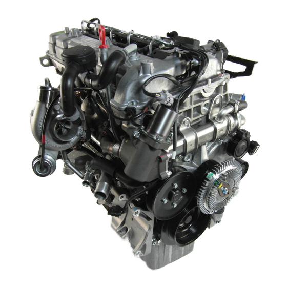
DI0A-8 STRUCTURE Front view Rear view Y220_0A001 1. TVD (Torsional Vibration Damper) 7. Cooling fan pulley & viscos clutch 13. Oil filter housing 2. Air conditioner compressor 8. Aut tensioner pulley 14. Vacuum pump 3. Power steering pump pulley 9. Auto tensioner 15. -
Page 8: Top View
DI0A-9 Top view Y220_0A002 19. Cylinder head cover 24. Fuel pipe 29. Booster pressure sensor 20. Intake manifold 25. Injector 30. Oil separator 21. Water outlet port 26. Fuel return line 31. Oil dipstic 22. Common rail 27. Oil filler cap 32. - Page 9 DI0A-10 Left side view Right side view Y220_0A003 33. Cylinder head 38. EGR - RH pipe 42. Turbocharger vacuum modulator 34. Cylinder block 39. Oil separator 43. EGR valve vacuum modulator 35. Oil pan 40. Oil dipstic 44. EGR valve 36.
- Page 10 DI0A-11 ENGINE CONTROLS ECU RELATED COMPONENTS Fuel filter ECU/barometric sensor Cam position sensor Accelerator pedal sensor (water detection sensor) HFM sensor/intake air Pre heating time relay Main relay temperature sensor Y220_0A004 GENERAL INFORMATION CHANGED BY DI ENG SM - 2004.4 EFFECTIVE DATE AFFECTED VIN...
- Page 11 DI0A-12 ENGINE AND SENSORS Crankshaft position Injector Common rail sensor Glow plug Fuel pressure sensor Camshaft position Booster pressure sensor sensor Coolant temperature HP pump Knock sensor (2) sensor Y220_0A005 GENERAL INFORMATION CHANGED BY EFFECTIVE DATE DI ENG SM - 2004.4 AFFECTED VIN...
- Page 12 DI0A-13 ELECTRICAL COMPONENTS AND PRE HEATING SYSTEM Glow plug Pre heating time relay Fuse box Battery Starter motor Alternator Y220_0A006 GENERAL INFORMATION CHANGED BY DI ENG SM - 2004.4 EFFECTIVE DATE AFFECTED VIN...
- Page 13 DI0A-14 INTAKE SYSTEM Air cleaner assembly HFM sensor Intake duct hose Intake manifold Intake outlet hose Turbocharger Intercooler Inlet hose Y220_0A007 GENERAL INFORMATION CHANGED BY EFFECTIVE DATE DI ENG SM - 2004.4 AFFECTED VIN...
- Page 14 DI0A-15 INTAKE AIR FLOW CHART Intake valve (in combustion chamber) Intake manifold Air cleaner side Turbo- charger Engine (compressor) HFM sensor Intake hose (outlet) Intercooler Intake hose (inner) Y220_0A008 GENERAL INFORMATION CHANGED BY DI ENG SM - 2004.4 EFFECTIVE DATE AFFECTED VIN...
- Page 15 DI0A-16 INTAKE SYSTEM Muffler Exhaust manifold EGR valve Turbocharger Catalytic converter EGR pipe Vacuum modulator Y220_0A009 GENERAL INFORMATION CHANGED BY EFFECTIVE DATE DI ENG SM - 2004.4 AFFECTED VIN...
- Page 16 DI0A-17 EXHAUST AIR FLOW CHART Catalytic converter Exhaust pipe Muffler Ambient Exhaust gas Turbocharger (turbine side) EGR vacuum modulator To turbocharger booster Turbocharger booster vacuum modulator Turbocharger booster EGR valve Exhaust manifold EGR pipe Y220_0A010 GENERAL INFORMATION CHANGED BY DI ENG SM - 2004.4 EFFECTIVE DATE AFFECTED VIN...
- Page 17 DI0A-18 LUBRICATION SYSTEM Engine oil filter Cylinder head cover Oil dipstic PCV valve housing Engine oil pressure Engine oil pump Oil pan Engine oil cooler switch Y220_0A011 GENERAL INFORMATION CHANGED BY EFFECTIVE DATE DI ENG SM - 2004.4 AFFECTED VIN...
- Page 18 DI0A-19 COOLING SYSTEM Coolant reservoir Water pump Cooling fan and fan Radiator assembly clutch Y220_0A013 GENERAL INFORMATION CHANGED BY DI ENG SM - 2004.4 EFFECTIVE DATE AFFECTED VIN...
- Page 19 DI0A-20 COOLANT FLOW CHART Heater Oil cooler Coolant reservoir Intake manifold Thermostat Coolant outlet port Water pump Inner hose Outlet hose Cooling fan Radiator Y220_0A014 GENERAL INFORMATION CHANGED BY EFFECTIVE DATE DI ENG SM - 2004.4 AFFECTED VIN...
- Page 20 DI0A-21 FUEL SYSTEM Fuel return hose Fuel pressure pipe Common rail Fuel filter Injector HP pump Priming pump Y220_0A015 GENERAL INFORMATION CHANGED BY DI ENG SM - 2004.4 EFFECTIVE DATE AFFECTED VIN...
-
Page 21: Fuel Supply System
DI0A-22 FUEL SUPPLY SYSTEM Fuel pressure sensor High pressure pump Common rail IMV valve High Low and high pressure pressure pump pipe Fuel temperature sensor Water separator Label Prining pump (C21) Fuel filter Water detection sensor Injector Sensors HFM sensor Cam position sensor Crank position sensor Fuel tank... - Page 22 DI0A-23 GENERAL SPECIFICATIONS VEHICLE SPECIFICATIONS Vehicle Dimension (mm) Y220_0A017 GENERAL INFORMATION CHANGED BY DI ENG SM - 2004.4 EFFECTIVE DATE AFFECTED VIN...
- Page 23 DI0A-24 Specifications Systems Items Diesel Remark General Overall length (mm) 4,720 (4,785) ( ): optional item Overall width (mm) 1,870 Overall height (mm) 1,760 (1,830) Gross vehicle weight (kg) AT: 2450 (2510), MT: 2405 (2465) Curb weight (kg) AT: 1995 (2055), MT: 1950 (2010) Min.
- Page 24 DI0A-25 Specifications (Cont’d) Systems Items Diesel Remark Transfercase Model Part-time ( ): optional item Type Planetary gear type Gear ratio High 1.000 : 1 2.483 : 1 Clutch Type Hydraulic [A/T: Torque converter] Disc type Dry single diaphragm type [A/T: 3 elements 1 stage 2 phases] Power Type Rack and pinion...
- Page 25 DI0A-26 MAINTENANCE Major Components and Service Interval * Use only Ssangyong Genuine Parts. Components Service Interval Remarks Daily Weekly More frequent maintenance is required if Engine Gasoline Initial change: 10,000 km the vehicle is operated under severe oil and engine Replace at every 15,000 km condition.
-
Page 26: Lubrication Chart
Propeller shaft grease - Front/Rear Properly * Please contact Ssangyong Dealer for approved alternative fluid. ** In only case not available MB 229.1 or 229.3, API or ACEA oil may be accepted, however it would rather recommend to shorten the change interval around 30%. -
Page 27: Vehicle Identification
Vehicle identification number (VIN) is is on the right front axle upper frame. [KPTPOA19S1P 122357] K .. Nation (K: Korea) P .. Maker Identification (P: Ssangyong Motor Company) T .. Vehicle Type (T: Passenger car - 4WD) P .. Line Models (P: Rexton) O . -
Page 28: Engine Serial Number
DI0A-29 3. Engine Serial Number The engine serial number is stamped on the lower area of cylinder block in exhaust manifold side. Y220_0A020 4. Manual Transmission Number The transmission label is affixed on the upper area of clutch housing. 5. Automatic Transmission Number The transmisson label is affixed on the right area of transmis- sion housing. - Page 29 DI0A-30 HOW TO USE AND MAINTAIN WORKSHOP MANUAL CONSISTS OF WORKSHOP MANUAL Consists of Small Group 1. Group: The manual is divided in large group like 1. Contents: In small group, included subjects and engine, transmission, axle and others and this group detailed subjects are described in.
- Page 30 DI0A-31 GUIDELINES FOR SERVICE WORK SAFETY General Cautions on Inspection/Service Notice During service works, be sure to observe below general items for your safety. • For service works, be sure to disconnect battery negative (-) terminal if not starting and inspection. •...
- Page 31 DI0A-32 Guidelines on Engine Service Fuel and lubrication system Painted surface of the body can be damaged or rubber To prevent personal injuries and vehicle damages that can products (hoes) can be corroded if engine oil and fuel are be caused by mistakes during engine and unit inspection/ spilled over.
- Page 32 DI0A-33 During Service Work - Inspection 1. Before lifting up the vehicle with lift, correctly support the lifting points and lift up. 2. When using a jack, park the vehicle on the level ground and block front and rear wheels. Position the jack under the frame and lift up the vehicle and then support with chassis stand before service work.
- Page 33 DI0A-34 8. Never reuse cotter pin, gasket, O-ring, oil seal, lock washer and self-locking nut. Replace them with new. If reused, normal functions cannot be maintained. 9. Align the disassembled parts in clean according to disassembling order and group for easy assembling. 10.
- Page 34 DI0A-35 During Service Work for Electric Devices Notice Be careful not to modify or alter electrical system and electrical device. Or there can be vehicle fire or serious damage. 1. Be sure to disconnect battery negative (-) terminal during every service work. Before disconnecting battery negative (-) terminal, turn off ignition key.
- Page 35 DI0A-36 LIFTING POINTS Lifting Positions 1. 4-post lift As illustrated, position the vehicle on the 4-post lift securely and block the front and rear of each tire not to move during working. Notice During lifting, be sure to check whether vehicle is empty. •...
-
Page 36: Tightening Torque Of Standard Bolts
DI0A-37 TIGHTENING TORQUE OF STANDARD BOLTS Tightening Torque By Bolt Specification Tightening Torque (kg . cm) Bolt Pitch Standard Tightening Torque Max. Allowable Tightening Torque Diameter 1.25 1.25 1.25 1,100 1.75 1,000 1,300 1,200 1,900 1,100 2,000 1,100 1,900 2,700 1,200 2,000 2,900... - Page 37 DI01-1 SECTION DI01 ENGINE ASSEMBLY Table of Contents STRUCTURE AND FUNCTION DESCRIPTIONS ..DI01-3 D27DT engine ............DI01-3 Engine performance curve ........DI01-8 General diagnosis ..........DI01-10 DIAGNOSTIC INFORMATION AND PROCEDURE .. DI01-15 Oil leak diagnosis ..........DI01-15 Compression pressure test ........DI01-16 Cylinder pressure leakage test ......
- Page 38 DI01-3 STRUCTURE AND FUNCTION DESCRIPTIONS D27DT ENGINE Major Components in Engine and Engine Compartment The advanced electronically controlled D27DT engine that has high pressure fuel system has been introduced to this vehicle. It satisfies the strict emission regulation and provides improved output and maximum torque. Y220_01001 1.
- Page 39 DI01-4 Engine Structure Front View Rear View Y220_01002 1. TVD (Torsional Vibration Damper) 7. Viscos fan clutch 13. Oil filter 2. Air conditioner compressor 8. Auto tensioner pulley 14. Vacuum pump 3. Power steering pump pulley 9. Auto tensioner 15. Crank position sensor 4.
- Page 40 DI01-5 Top View Y220_01003 19. Cylinder head cover 24. Fuel pipe 29. Booster pressure sensor 20. Intake manifold 25. Injector 30. PCV valve and oil separator 21. Water outlet port 26. Fuel return line 31. Oil dipstick 22. Common rail 27.
- Page 41 DI01-6 Left Side View Right Side View Y220_01004 33. Cylinder head 38. EGR-RH pipe 42. Turbo charger booster vacuum 34. Cylinder block 39. PCV valve and oil separator modulator 35. Oil pan 40. Oil dipstick 43. EGR valve vacuum modulator 36.
- Page 42 DI01-7 Specifications Description Specification Engine Type/Number of cylinders D27DT/5-cylinder 86.2 Cylinder Inner diameter (mm) Stroke (mm) 92.4 2696 Displacement (cc) 18:1 Compression ratio 170/4,000 Maximum output (ps/rpm) Maximum torque (kg . m/rpm) 34.7/1,800 750 ± 50 rpm For Manual Transmission Idle speed 750 ±...
- Page 43 DI01-8 ENGINE PERFORMANCE CURVE Output and Torque Speed [rpm] Y220_00025 ENGINE ASSEMBLY CHANGED BY EFFECTIVE DATE DI ENG SM - 2004.4 AFFECTED VIN...
- Page 44 DI01-9 Oil Temperature/Pressure and Boost Pressure Speed [rpm] Y220_00026 ENGINE ASSEMBLY CHANGED BY DI ENG SM - 2004.4 EFFECTIVE DATE AFFECTED VIN...
- Page 45 DI01-10 GENERAL DIAGNOSIS Condition Probable Cause Correction Hard Starting Malfunction of • Faulty fuse. • Replace the fuse. (With normal Ignition System • Faulty spark plug. • Clean, adjust the plug gap or cranking) replace. • • Electric leakage at the high Replace the cable.
- Page 46 DI01-11 GENERAL DIAGNOSIS (Cont’d) Condition Probable Cause Correction Lack of Engine Malfunction of • • Clogged fuel pipe. Clean the pipe. Power Fuel System • • Clogged or contaminated fuel Replace the filter. filter. • Others • Clogged exhaust system. Check and repair the system.
- Page 47 DI01-12 GENERAL DIAGNOSIS (Cont’d) Condition Probable Cause Correction Engine Surging Decline of • • Refer to “Compression Pressure Refer to “Compression Pressure (Engine power Compression Test”. Test”. makes Pressure fluctuation in a Malfunction of • • Clogged fuel pipe. Clean the pipe. fixed speed and Fuel System •...
- Page 48 DI01-13 GENERAL DIAGNOSIS (Cont’d) Condition Probable Cause Correction Poor Fuel Decline of • • Refer to “Compression Pressure Refer to “Compression Pressure Consumption Compression Test”. Test”. Pressure Malfunction of • • Leakage of the fuel tank or the Repair or replace the fuel tank or Fuel System fuel pipe.
- Page 49 DI01-14 GENERAL DIAGNOSIS (Cont’d) Condition Probable Cause Correction Engine Noise Valve Noise • • Inadequate valve clearance Adjust the valve clearance. • • Abrasion of valve stem or guide. Replace the valve stem or the guide. • • Weak valve spring. Replace the spring.
- Page 50 DI01-15 DIAGNOSTIC INFORMATION AND PROCEDURE OIL LEAK DIAGNOSIS Black Light and Dye Method Most fluid oil leaks are easily located and repaired by vi- A dye and light kit is available for finding leaks, Refer to sually finding the leak and replacing or repairing the nec- the manufacturer's directions when using the kit.
- Page 51 DI01-16 COMPRESSION PRESSURE TEST The compression pressure test is to check the conditions of internal components (piston, piston ring, intake and exhaust vale, cylinder head gasket). This test provides current engine operating status. Notice • Before cranking the engine, make sure that the test wiring, tools and persons are keeping away from moving components of engine (e.g., belt and cooling fan).
- Page 52 DI01-17 Measuring Procedure Notice • Disconnect the fuel rail pressure sensor connector to cut off the fuel injection. • Discharge the combustion residues in the cylinders before testing the compression pressure. • Apply the parking brake before cranking the engine. 1.
- Page 53 DI01-18 CYLINDER PRESSURE LEAKAGE TEST If the measured value of the compression pressure test is not within the specifications, perform the cylinder pressure leak- age test. Y220_01009 Permissible Pressure Leakage Test temperature at normal operating temperature (80°C) At whole engine Max.
- Page 54 DI01-19 TIGHTENING TORQUE Name Size Quantity Tightening Torque Oil nozzle M6 x 22 10 ± 1 55 ± 5 Main bearing cap M11 x 62 90° ± 10° 40 ± 5 Connecting rod cap M9 x 52 90° ± 10° Rear cover M6 x 20 10 ±...
- Page 55 DI01-20 Name Size Quantity Tightening Torque M8 x 45(LOWER) 32 ± 3 Auto tensioner M12 x 90 82 ± 6 Water pump assembly M6 x 50 10 ± 1 Water pump pulley M6 x 12 10 ± 1 Hot water inlet pipe assembly M6 x 12 10 ±...
- Page 56 DI01-21 Name Size Quantity Tightening Torque Vacuum modulator M6 x 16SOC 10 ± 1.0 WDT combination bolt M6 x 16 10 ± 1.0 Oil dipstick tube M6 x 16 10 ± 1.0 M8 x 35SOC 25 ± 2.5 Oil filter assembly M8 x 50SOC 25 ±...
- Page 57 DI01-22 REMOVAL AND INSTALLATION ENGINE MOUNTING 1. Side Mountings Left Right 2. Transmission Mounting 3. Exhaust Manifold and Pipe 4. Cables and Connectors Y220_01010 Notice 1. Disconnect the negative battery cable before removal. 2. Drain the engine oil. 3. Drain the engine coolant. 4.
- Page 58 DI01-23 Engine Assembly - Removal 1. Disconnect the negative battery cable. Notice If not necessary, place the ignition switch at “OFF” position. Y220_01011 2. Remove the engine hood assembly. Note Refer to “Body” section. Y220_01012 3. Remove the skid plate under the engine compartment. Installaiton Notice Tightening torque 12 ±...
- Page 59 DI01-24 5. Loosen the cylinder block drain plug (under the intake manifold) and drain the coolant completely. 6. Retighten the drain plug with the specified tightening torque. Tightening torque 30 Nm Y220_01015 7. Remove the inlet hose (1) and the heater hose (2) under the radiator.
- Page 60 DI01-25 10. Loosen the hose clamp on intake air hose of turbo charger and remove the intake air hose. Y220_01022 11. Separate the outlet hose of oil separator from the intake air hose of turbo charger. 12. Loosen the clamp on the intake air duct hose of turbo charger at the air cleaner side and separate the hose from the air cleaner housing.
- Page 61 DI01-26 15. Loosen the clamp on the intake manifold and remove the intake air hose. Y220_01024 16. Remove the exhaust pipe mounting nuts from the turbo charger. Installation Notice Tightening torque 25 ± 2.5 Nm Y220_01027 17. Remove the power steering inlet pipe and the outlet hose from the power steering pump.
- Page 62 DI01-27 19. Remove the supply inlet, supply outlet and return hose from the fuel filter. Notice 1. When separating the hoses from the fuel filter, plug the openings with caps so that the contaminants will not get into the fuel system. 2.
- Page 63 DI01-28 24. Disconnect the air conditioner compressor connector and remove the inlet and outlet pipes from the compressor. Y220_01034 25. For the automatic transmission equipped vehicle, remove the oil cooler pipes. Y220_01035 Note The oil cooler pipes are connected to cylinder block at both sides and bottom area of oil with brackets.
- Page 64 DI01-29 27. Remove the radiator shroud. Installation Notice Tightening torque 10 ± 1.0 Nm Y220_01039 28. Take off the fan belt from the engine. Note 1. Insert a tool into the belt tensioner and rotate it counterclockwise to take off the fan belt. 2.
- Page 65 DI01-30 29. Remove the transmission mounting bolts and separate the engine assembly from the transmission assembly. Y220_01041 Note 1. Before unscrewing the transmission mounting bolts, remove the starter motor. Installation Notice Mounting bolt 55 ± 5 Nm ENGINE ASSEMBLY CHANGED BY EFFECTIVE DATE DI ENG SM - 2004.4 AFFECTED VIN...
- Page 66 DI01-31 30. Remove the engine assembly mounting nuts at both sides. Installation Notice Mounting Nut 55 ± 5 Nm Y220_01042 31. Hook the chain on the engine brackets and carefully 32. Put the removed engine assembly on the safety stand. pull out the engine assembly from the vehicle by using a hoist or crane.
- Page 67 DI01-32 DISASSEMBLY AND REASSEMBLY COMPONENTS AND SPECIAL TOOLS Injector puller Glow plug puller Fuel pipe wrench Sealing caps Injector copper washer puller Engine lock Valve remover/installer Pulley lock/wrench HP pump lock HP pump bearing puller Y220_01044 ENGINE ASSEMBLY CHANGED BY EFFECTIVE DATE DI ENG SM - 2004.4 AFFECTED VIN...
- Page 68 DI01-33 Inspection Before Disassembly and Reassembly Preparations and Preceding Works 1. Remove the cylinder block drain plug and seal and completely drain the residual coolant from the cylinder block. Tightening torque 30 Nm Notice Y220_01045 Replace the seal with new one once removed. 2.
- Page 69 DI01-34 Accessories - Removal and Installation EGR valve pipe (LH, Center, RH) PCV valve and oil separator Power steering pump Turbo charger Cooling fan clutch Auto tensioner Alternator Fuel return hose Cable and connector Oil filter assembly EGR valve Start motor Air conditioner compressor Mounting bracket Y220_01048...
- Page 70 DI01-35 • The engine accessories can be removed without any specific order. In general, remove the components from top to bottom. However, be careful not to splash the lubricants to engine and body when disassembly. Especially, avoid getting into other components. Removal and Installation Order of Major Accessories * Camshaft Position Sensor 1.
- Page 71 DI01-36 1. Remove the fuel pipes. A. Remove the fuel supply pipes between each cylinder and common rail with a special tool. Installation Notice Tightening torque 40 ± 4.0 Nm Y220_01049 Notice 1. Plug the openings of injector nozzle and common rail with sealing caps after removed the fuel pipes.
- Page 72 DI01-37 C. High fuel pressure supply pipe at HP pump side Installation Notice Tightening torque 40 ± 4.0 Nm Y220_01053 D. Unscrew the bracket mounting bolts and remove the high fuel pressure supply pipes. Note Special tool: Fuel pipe remover and installer Y220_01055 Y220_01054 ENGINE ASSEMBLY...
- Page 73 DI01-38 2. Disconnect the vacuum hoses and module cables from the vacuum modulator. Notice Put the installation marks on the modulator hoses and connectors. To EGR valve EGR vacuum booster vacuum modulator Turbo charger booster vacuum modulator From vacuum pump To turbo charger booster Y220_01056...
- Page 74 DI01-39 3. Disconnect the wiring harnesses and connectors from the engine. Injector fuel line Fuel return hose Glow plug connector connector Camshaft position Crankshaft position sensor sensor HP pump connector Oil pressure switch Fuel temperature Sensor Coolant temperature Booster pressure sensor Fuel pressure sensor Knock sensor connector sensor connector...
- Page 75 DI01-40 A. Remove the cable assembly from the engine. Important 1. If possible, remove the cables after removing the fuel pipes. It make the operation easier and protect the cables and connectors. Y220_01059 2. Remove the cable screws and ground cable, and then remove the engine cable assembly.
- Page 76 DI01-41 5. Remove the EGR valve and EGR valve pipe. A. Disconnect the vacuum hose from the EGR valve. B. Unscrew the EGR valve bolts and EGR #1 pipe connecting bolts and remove the EGR valve and steel gasket. Installation Notice EGR valve bolt 25 ±...
- Page 77 DI01-42 B. Remove the oil filter assembly mounting bolts. Notice Be careful not to flow out the residual oil from the engine. If flown out, immediately wipe it out. Y220_01066 C. Remove the oil filter assembly from the cylinder block. Installation Notice - Replace the oil filter gasket with new one.
- Page 78 DI01-43 C. Remove the belt tensioning device. Notice • To prevent the oil leaks, store the removed shock absorber assembly with standing up. • For air bleeding, pump the shock absorber around 3 times after installation. • Be careful not to damage the rubber parts of the shock absorber when removing.
- Page 79 DI01-44 B. Unscrew the bolts and remove the air conditioner mounting bracket. Installation Notice Front bolt 25 ± 2.5 Nm Side bolt 25 ± 2.5 Nm Y220_01074 9. Remove the PCV valve assembly. A. Remove the PCV valve hose. Y220_01075 B.
- Page 80 DI01-45 10. Remove the oil dipstick tube assembly. Unscrew the bracket bolts and remove the dipstick tube with O-ring. Installation Notice Insert new O-ring into the oil dipstick tube before installation. Y220_01078 Installation Notice Tightening torque 10 ± 1.0 Nm Y220_01079 11.
- Page 81 DI01-46 C. Unscrew the turbo charger mounting bracket bolts. Installation Notice Tightening torque 25 ± 2.5 Nm Y220_01082 D. Unscrew the turbo charger mounting bolts to exhaust manifold. Notice Use only 12 1/2 wrench. Installation Notice Tightening torque 25 ± 2.5 Nm Y220_01083 E.
- Page 82 DI01-47 B. Remove the alternator mounting bracket. Installation Notice M13 bolt 25 ± 2.5 Nm Torx 6 bolt 25 ± 2.5 Nm Y220_01086 ENGINE ASSEMBLY CHANGED BY DI ENG SM - 2004.4 EFFECTIVE DATE AFFECTED VIN...
- Page 83 DI01-48 Engine - Disassembly and Reassembly 1. Unscrew the injector nozzle holder bolts (12-sided) and remove the injector bracket. Installation Notice 9 ± 1.0 Nm, Tightening torque 190° + 10° Y220_01089 2. Remove the injectors with a injector extractor (special tool).
- Page 84 DI01-49 4. Remove the glow plugs with a special tool. Installation Notice Tightening torque 15 ± 3 Nm Y220_01091 5. Unscrew the Torx bolts and remove the common rail from the engine. Installation Notice Tightening torque 25 ± 2.5 Nm Notice Plug the openings with sealing cap.
- Page 85 DI01-50 8. Unscrew the bolts and remove the cooling fan pulley while holding it with a special tool. Tightening torque 10 ± 1.0 Nm Y220_01094 9. Remove the cooling fan belt idle pulley while holding it with a special tool. Tightening torque 10 ±...
- Page 86 DI01-51 12. Turn over the engine and remove the oil pan. Installation Notice Tightening torque M6 x 20: 24 EA 10 ± 1.0 M6 x 35: 2 EA 10 ± 1.0 M6 x 85: 2 EA 10 ± 1.0 M8 x 40: 4 EA 25 ±...
- Page 87 DI01-52 14. Unscrew the bolts and remove the thermostat. Installation Notice Tightening torque 10 ± 1.0 Nm Notice Be careful not to flow out the residual coolant. Y220_01104 15. Unscrew the bolts and remove the water pump. Installation Notice Tightening torque 10 ±...
- Page 88 DI01-53 18. Unscrew the bolts and remove the intake manifold assembly. Installation Notice Tightening torque 25 ± 2.5 Nm Y220_01108 Notice Replace the gasket with new one once removed. Y220_01109 19. Remove the vacuum pump from the cylinder head. Installation Notice Tightening torque 10 ±...
- Page 89 DI01-54 21. Remove the chain tensioner. Preceding works: removal of EGR pipe and oil dipstick tube Tightening torque 65 ± 5.0 Nm Y220_01119 22. Pull out the lock pin and remove the upper chain guide bracket. Y220_01112 23. Unscrew the bolt and remove the intake camshaft sprocket.
- Page 90 DI01-55 25. Remove the camshaft bearing cap bolts so that the tightening force can be relieved evenly. Exhaust • Intake: #1, #3, #6 • Exhaust: #7, #9, #12 * However, there is no specific removal sequence. Intake Y220_01115 • Intake: #2, #4, #5 •...
- Page 91 DI01-56 28. Pull out the pin and remove the timing chain guide from the engine. Y220_01120 29. Remove the cylinder head bolts according to the numerical sequence. Installation Notice Tightening torque M8 x 25: 2 EA 25 ± 2.5 M8 x 50: 2 EA 25 ±...
- Page 92 DI01-57 32. Measure the piston protrusion from the parting surface. • Specified Value: 0.765 ~ 1.055 mm Y220_01124 33. Remove the cylinder head gasket. Installation Notice • Replace the cylinder head gasket with new one. Make sure to place the “TOP” mark upward. 1.
- Page 93 DI01-58 35. Unscrew the bolts and remove the oil strainer assembly. Installation Notice Tightening torque 25 ± 2.5 Nm Y220_01128 36. Remove the piston assembly from the cylinder block. A. Unscrew the bearing cap bolts. Installation Notice Step 1 55 ± 5.0 Nm Step 2 90°...
- Page 94 DI01-59 D. Remove the snap ring piston pin from the piston. E. Disassemble the piston and connecting rod. F. Remove the piston rings from the piston. Installation Notice Replace the piston ring, bearing and snap ring with new ones. Y220_01132 37.
- Page 95 DI01-60 39. Remove the timing chain guide rail and timing chain. Y220_01136 40. Remove the HP pump bolts and the HP pump bracket bolts. Y220_01138 • Remove the HP pump assembly. Y220_01139 41. Remove the crankshaft sprocket with a special tool. Y220_01137 ENGINE ASSEMBLY CHANGED BY...
- Page 96 DI01-61 42. Remove the flywheel and the crankshaft strainer. Installation Notice 45 ± 5.0 Nm, Tightening torque 90° + 10° 43. Unscrew the bolts and remove the crankshaft bearing caps. Installation Notice 55 ± 5.0 Nm, Tightening torque 90° + 10° Y220_01140 Notice •...
- Page 97 DI02-1 SECTION DI02 ENGINE HOUSING Table of Contents CYLINDER HEAD/CYLINDER BLOCK ....... DI02-3 Cylinder head ............DI02-3 Camshaft assembly ..........DI02-17 Timing chain assembly .......... DI02-25 Cylinder block ............DI02-29 CRANKSHAFT ............DI02-32 Arrangement of thrust washers and bearings ..DI02-33 Torsional vibration damper ........
-
Page 98: Cylinder Head
DI02-3 CYLINDER HEAD/CYLINDER BLOCK CYLINDER HEAD Cylinder head bolt Oil return check valve Y220_02001 System Characteristics • 4-valve DOHC valve mechanism Intake port • Swirl and tangential port • 4-bolt type cylinder head bolt • Water jacket integrated casting • Integrated chain housing and cylinder head •... - Page 99 DI02-4 Cylinder Head Pressure Leakage Test Preceding Works: - Removal of cylinders - Removal of intake and exhaust manifold - Removal of valves Test Procedures 1. Place the pressure plate on a flat-bed work bench. Y220_02003 2. Install the cylinder head on the pressure plate. Tightening torque 60 Nm 3.
- Page 100 DI02-5 Cylinder Head Parting Surface Check Specifications Height “A” (cylinder head parting surface - cylinder head cover parting surface) 142.9 ~ 143.1 mm Minimum height after machining 142.4 mm Permissible unevenness of parting surface in longitudinal direction 0.08 mm in transverse direction 0.0 mm Permissible variation of parallelism of top parting surface to bottom in longitu- within 0.1 mm...
- Page 101 DI02-6 Cylinder Head - Disassembly and Reassembly Disassembly Preceding Works: - Removal of fan belt - Removal of fuel supply and return lines - Removal of EGR related pipes - Removal of intake manifold mounting bracket - Removal of injector fuel line and connector, and glow plug connector Y220_02007 Notice...
- Page 102 DI02-7 4. Remove the chain tensioner. Preceding work: removal of EGR pipe and oil dipstick tube Y220_02012 5. Hold the camshafts and remove the intake camshaft sprocket and exhaust camshaft sprocket. Y220_02013 6. Pull out the lock pins with a sliding hammer and remove the upper guide rail.
- Page 103 DI02-8 8. Remove the cylinder head bolts according to the numerical sequence. M8 x 25 : 2 EA M8 x 50 : 2 EA M12 x 177 : 11 EA M12 x 158 : 1 EA (Vacuum pump side) Y220_02016 9.
- Page 104 DI02-9 Reassembly 1. Install the cylinder head with the steel gasket. Notice Make sure to place the “TOP” mark upward. Y220_02020 2. Tighten the cylinder head bolts to specified torque and torque angle. Step 1 20 ± 2.0 Nm Tightening torque Step 2 85 ±...
- Page 105 DI02-10 • Exhaust: #1, #3, #6 Exhaust • Intake: #7, #9, #12 Tightening torque 25 Nm Notice Check the finger follower positions and align if needed. Intake Y220_02024 5. Install the intake and exhaust camshaft sprockets and the timing chain. Tightening torque 25 Nm + 90°...
- Page 106 DI02-11 8. Fit the timing chain onto the camshaft sprockets and install the upper guide rail. • Install the clamping guide rail pin. Notice • Install the guide rail with slanted side facing forward. • Be careful not to change the timing of HP pump when fitting the timing chain.
- Page 107 DI02-12 14. Install the chain tensioner. Tightening torque 80 ± 8.0 Nm Y220_02032 15. Install the cylinder head cover assembly. 16. Install the rubber gasket. Y220_02033 17. Tighten the cylinder head cover bolts. Notice • Apply the sealant to the bolts for the vacuum pump and the timing chain cover.
- Page 108 DI02-13 22. Install the PCV valve assembly on the cylinder head. Tightening torque 10 ± 1.0 Nm Y220_02035 23. Engage the engine oil hose and the PCV valve hose. Y220_02036 24. Remove the protective caps and install the new fuel supply pipes.
- Page 109 DI02-14 Intake/Exhaust - Removal/Installation 1. Remove the cylinder head assembly. Y220_02039 2. Install the removed cylinder head on the assembly board (special tool) and set the supporting bar and lever (special tool) on the cylinder head. Y220_02040 3. Push the valve spring seat down with the lever and remove the valve cotter, valve seat and valve spring.
- Page 110 DI02-15 Special Tools and Equipment Name and Part Number Application Compression pressure measur- ing adapter and gauge Y220_02044 Y220_02043 Pressure plate (cylinder head pressure leakage test) Y220_02045 Y220_02046 Pressure plate (intake camshaft pressure leakage test Y220_02047 Y220_02048 Pressure plate (exhaust camshaft pressure leakage test) Y220_02049 Y220_02050...
- Page 111 DI02-16 Name and Part Number Application Cylinder head hanger Y220_02051 Y220_02052 Supporting bar and lever Y220_02053 Y220_02054 Guide pin extractor Y220_02056 Y220_02055 Intake manifold guide pin Y220_02057 Y220_02058 ENGINE HOUSING CHANGED BY EFFECTIVE DATE DI ENG SM - 2004.4 AFFECTED VIN...
- Page 112 DI02-17 CAMSHAFT ASSEMBLY Preceding Work: Removal of cylinder head cover Intake camshaft and Finger follower and HLA Camshaft sprockets exhaust camshaft Cylinder head Camshaft position sensor Chain tensioner Y220_02059 ENGINE HOUSING CHANGED BY DI ENG SM - 2004.4 EFFECTIVE DATE AFFECTED VIN...
- Page 113 DI02-18 Camshaft Position Sensor Hall voltage <Location of camshaft position sensor> <Operation principle of hall sensor> Y220_02060 The camshaft position sensor uses hall-effect to set the camshaft position and metallic-magnetic-material sensor end is attached on the camshaft and then rotates with it. If sensor protrusion passes camshaft position sensor’s semi-conduc- tor wafer, magnetic field changes direction of electron on the semi-conductor wafer to the current flow direction that passes through wafer from the right angle.
- Page 114 DI02-19 Removal Preceding Works: - Removal of fan belt - Removal of fuel supply and return lines - Removal of intake manifold mounting bracket 1. Remove the injector fuel line and connector, and glow plug connector Notice Plug the openings of injector holes and common rail with the protective caps.
- Page 115 DI02-20 4. Mark on the intake camshaft sprocket and exhaust camshaft sprocket for timing setting during installation. Y220_02066 5. Remove the chain tensioner. Preceding work: removal of EGR pipe and oil dipstick tube Y220_02067 6. Hold the camshafts and remove the intake camshaft sprocket and exhaust camshaft sprocket.
- Page 116 DI02-21 • Intake: #2, #4, #5 • Exhaust: #8, #10, #11 * Do not remove the bolts at a time completely. Remove them step by step evenly or camshaft can be seriously damaged. 8. Remove the intake and exhaust camshafts from the cylinder head.
- Page 117 DI02-22 Installation 1. Install the HLA device and finger follower. Check the HLA device with the diagnosis procedures before installation. Notice • Put the cylinder head on the locating pins. Y220_02072 2. Place the bearing cap with the OT marks on both camshafts facing upward.
- Page 118 DI02-23 4. Install the intake and exhaust camshaft sprockets and the timing chain. Tightening torque 25 Nm + 90° + 10° Notice • If the sprocket bolt is stretched over 0.9 mm, replace it with new one. • Always install the intake camshaft sprocket first. •...
- Page 119 DI02-24 Special Tools and Equipment Name and Part Number Application HLA remover Y220_02080 Y220_02081 Stem seal drift Y220_02082 Y220_02083 ENGINE HOUSING CHANGED BY EFFECTIVE DATE DI ENG SM - 2004.4 AFFECTED VIN...
- Page 120 DI02-25 TIMING CHAIN ASSEMBLY Chain Drive System System Layout Oil injecting direction Y220_02084 1. Exhaust camshaft sprocket 7. Oil pump tensioner 2. Upper guide rail 8. Oil pump sprocket 3. Intake camshaft sprocket 9. Crankshaft sprocket 4. Clamping guide rail 10.
- Page 121 DI02-26 Chain • Chain type: Double Bush • Pitch: 9.525 mm • Load limits: 19,000 N • No. of links: 144 EA • Overall length: 1371.6 mm • Replace when the chain is extended by 0.5 % from overall length (Replace if extended by over 6.858 mm) Chain tensioner Check valve * Check valve opening pressure: 0.2 ~ 0.5 bar...
- Page 122 DI02-27 Timing setting Sprocket marking: 4 points (Gold marking) <Timing marking points on chain> Y220_02086 • Check marking links on the chain (Gold marking) • Locate a point with two continuous marking links and align it to a marking on crankshaft sprocket ( ) •...
- Page 123 DI02-28 Removal and Installation 1. Remove the cylinder head assembly. 2. Remove the oil pan. 3. Remove the chain guide rail with a sliding hammer. 4. Remove the chain cover. Y220_02087 5. Remove the oil pump drive chain. 6. Remove the upper guide rail while pushing the retaining spring with a screwdriver.
-
Page 124: Cylinder Block
DI02-29 CYLINDER BLOCK Deep head bolt thread to prevent the deformation at cylinder bore surfaces Internal and external ribs considered Water jacket design to increase vibration and strength the cooling efficiency Cambering type skirt to reduce the noise Y220_02091 System Characteristics •... - Page 125 DI02-30 Knock Sensor Two knock sensors are located on the cylinder block (intake manifold side). To detect engine vibration under abnormal combustion, knock sensor has piezoelectric element fixed on the vibration plate and this vibration plate is fixed on the base. If happens knocking, pistons or connecting rods vibrate and occurs heavy sounds that hit metal.
- Page 126 DI02-31 Notice The knock sensor should be tightened with the specified tightening torque. Otherwise, the engine output may be decreased and the “ENGINE CHECK” warning lamp may come on. The internal resistance of the sensor is approx. 4.7 k Ω Ω Ω Ω Ω . Ground Knock sensor Signal...
- Page 127 DI02-32 CRANKSHAFT Preceding Works: Removal of end cover Removal of pistons Removal of crankshaft sprocket Y220_02094 3. Crankshaft main bearing shells, upper 7. Lower thrust bearing 4. Upper thrust bearing 8. Crankshaft main bearing cap 5. Crankshaft 9. Crankshaft thrust bearing cap 6.
- Page 128 DI02-33 ARRANGEMENT OF THRUST WASHERS AND BEARINGS Y220_02095 1. Crankshaft 4. Crankshaft main bearing shells, lower 2. Crankshaft main bearing shells, upper 5. Lower thrust bearing 3. Upper thrust bearing Notice The clearance between bearing shell and bore and between bearing shell and journal are various.
- Page 129 DI02-34 Dimensions of Crankshaft Main Bearing (mm) Color Crankshaft Journal Upper Main Bearing Lower Main Bearing Blue 57.965 ~ 57.960 2.260 ~ 2.255 2.260 ~ 2.255 Yellow 57.960 ~ 57.955 2.265 ~ 2.260 2.265 ~ 2.260 57.955 ~ 57.950 2.270 ~ 2.265 2.270 ~ 2.265 White 57.950 ~ 57.945...
- Page 130 DI02-35 Selection of Upper Main Bearing Shell Punch Mark Color • Blue • • Yellow • • • Y220_02096 Selection of Lower Main Bearing Shell Mark Color Blue Yellow White Violet Y220_02097 ENGINE HOUSING CHANGED BY DI ENG SM - 2004.4 EFFECTIVE DATE AFFECTED VIN...
- Page 131 DI02-36 Crankshaft Position Sensor Permanent magnet Iron coil Standard position Ring gear <Location of crankshaft position sensor> <Structure of crankshaft position sensor> Y220_02098 The crankshaft position sensor is located near to flywheel on the rear of cylinder block. It generates AC voltage between increment type driven plate that fixed on flywheel inside.
- Page 132 DI02-37 Ground Signal Crankshaft position sensor Drive plate <Circuit diagram of crankshaft position sensor> Y220_02100 Min. voltage: 1.0 V (40 rpm, air gap: 1.3 mm) Output voltage ( 1 ~ 150 V) Max voltage: 150 V (7000 rpm, air gap: 0.3 mm) Ω...
- Page 133 DI02-38 TORSIONAL VIBRATION DAMPER Laser welding Bearing Cover Bushing Inertia ring Silicone oil Y220_02101 System Description • Components: Hub, inertia mass, cover, bearing, bushing, silicon oil • Functions: The crankshaft pulley optimizes the drive system by reducing the amount of torsional vibration in crankshaft. Conventional rubber damper is limited in changing materials (rubbers) to absorb vibration, but this crankshaft pulley (viscous damper), using silicon oil, takes advantage of less changing viscosity according to the temperature.
- Page 134 DI02-39 Crankshaft - Disassembly 1. Unscrew the bolts and remove the connecting rod journal bearing and bearing caps. Notice Position the #1 piston at TDC and remove the piston connecting rod journal bearing caps. 2. Remove the bearing cap bolts. Y220_02102 3.
- Page 135 DI02-40 Crankshaft - Reassembly 1. Thoroughly clean the oil galleries and check the journal section and bearings. Replace if necessary. Y220_02106 2. Coat the upper thrust washers with oil and insert into the crankcase so that the oil grooves are facing the crank webs (arrow).
- Page 136 DI02-41 6. Position the #1 piston at TDC and install the crankshaft. 7. Install the piston connecting rod journal to the crankshaft journal and tighten the bolts. 8. Measure the crankshaft bearing axial clearance. • When new: 0.100 ~ 0.245 mm •...
-
Page 137: Piston And Connecting Rod
DI02-44 PISTON AND CONNECTING ROD Y220_02114 1. Piston 4. Oil ring 2. No.1 compression ring 5. Piston pin 3. No.2 compression ring 6. Snap ring Description D27 DT ENG φ 86.2 Cylinder bore diameter (0~0.018) φ 86.133 Piston outer diameter (D1) (±0.009) Clearance between bore and piston Piston cooling gallery... - Page 138 DI02-45 PISTON RING 1. No.1 compression ring 2. No.2 compression ring 3. Oil ring 5. Coil spring and oil control ring 6. Hook spring Y220_02115 Replacement of Piston Ring • Measure piston ring end play. - Piston ring end play (mm) 1st groove: 0.20 ~ 0.35 2nd groove: 0.20 ~ 0.35 3rd groove: 0.20 ~ 0.40...
- Page 139 DI02-46 CYLINDER INNER DIAMETER AND PISTON SIZE Y220_02117 (Unit : mm) Engine Code Used piston Cylinder Diameter Piston Diameter D27DT A or X 86.200 ~ 86.206 86.124 ~ 86.130 A, B or X 86.206 ~ 86.212 86.129 ~ 86.137 B or X 86.212 ~ 86.218 86.136 ~ 86.142 86.250 ~ 86.260...
- Page 140 DI02-47 Piston - Reassembly 1. Install the compression ring and oil ring on the piston with a special tool. Y220_02118 Arrange the piston ring ends to be 120° apart. Notice • Install the No.1 and No.2 pistons so that “Y” marking on piston head is facing upward.
- Page 141 DI02-48 4. Fit the piston onto connecting rod so that the marking on piston crown and locking slot are facing to straight ahead direction. Notice Install the piston so that the piston recess (marking) or the stamped surface of connecting rod is facing to straight ahead direction.
- Page 142 DI02-49 10. Measure stretch shaft diameter of the connecting rod bolts. Limit “C” 7.1 mm Y220_02126 11. Lubricate the new connecting rod bolts and tighten. 40 ± 5.0 Nm, Tightening torque 90° + 10° • End play of connecting rod cap Specified value 0.5 ~ 1.5 mm Y220_02127...
- Page 143 DI02-50 Special Tools and Equipment Name and Part Number Application Piston protrusion measuring jig Y220_02129 Y220_02130 Piston insertion jig Y220_02131 Y220_02132 ENGINE HOUSING CHANGED BY EFFECTIVE DATE DI ENG SM - 2004.4 AFFECTED VIN...
- Page 144 DI02-51 HIGH PRESSURE PUMP (HPP) COMPONENTS LOCATOR High pressure line Low pressure line Venturi return line Fuel temperature sensor IMV connector Inlet Metering Valve (IMV) High pressure supply line Y220_02133 1. Inlet Metering Valve (IMV) 7. Low pressure pump 2. Hydraulic pressure head 8.
- Page 145 DI02-52 HP Pump - Disassembly and Reassembly Preceding works: - Removal of fan belt (including cooling fan and fan clutch) and fan shroud - Removal of intake manifold assembly - Removal of water pump pulley - Removal of auto tensioner - Removal of EGR pipe - Removal of oil dipstic gauge Y220_02134...
- Page 146 DI02-53 3. Remove the cooling fan bracket assembly. Notice Be careful not to get the sealant or foreign materials into the engine. Y220_02137 4. Place the marks on the chain and HP pump sprocket for installation. Y220_02138 5. Remove the vacuum modulator bracket. 6.
- Page 147 DI02-54 8. While insert finger and push the chain guide backward direction and turn the crankshaft pulley to ATDC 65° by counter clockwise direction until feel the chain guide inclined backward. Y220_02139 9. Install a special tool into the cooling fan bracket hole to hold the sprocket.
- Page 148 DI02-55 12. Remove the HP pump mounting bracket. Installation Notice Tightening torque 24 ± 2.4 Nm Y220_02143 13. Unscrew the external bolts and remove the HP pump while rocking and tapping it with a rubber hammer. Notice • To prevent HP pump shaft damaging, do not apply excessive impact.
- Page 149 DI02-56 Notice If the initialization of fuel pressure has not been performed, the engine ECU controls new HP pump with the stored offset value. This may cause the poor engine output. Install in the reverse order of removal and tighten the fasteners with the specified tightening torque.
- Page 150 DI03-1 SECTION DI03 INTAKE SYSTEM Table of Contents AIR FLOWS ..............DI03-3 INTAKE SYSTEM LAYOUT ......... DI03-4 Components locator ..........DI03-4 Air cleaner ............... DI03-5 Air flow sensor (hot film air mass sensor) ........DI03-8 Intercooler ............. DI03-14 Intake manifold assembly ........DI03-16 SPECIAL TOOLS AND EQUIPMENT ......
- Page 151 DI03-3 AIR FLOWS Intake Valve (in combustion chamber) Intake Manifold Air Cleaner Turbo Charger Engine HFM Sensor Intake Air Outlet Hose Intercooler Intake Air Inlet Hose Y220_03001 Work Flow of Intake System Combustion Turbo Intake Chamber in Intercooler Cleaner Sensor Charger Manifold Engine...
- Page 152 DI03-4 INTAKE SYSTEM LAYOUT COMPONENTS LOCATOR Air cleaner Intake manifold HFM sensor Intercooler Y220_03002 INTAKE SYSTEM CHANGED BY EFFECTIVE DATE DI ENG SM - 2004.4 AFFECTED VIN...
-
Page 153: Air Cleaner
DI03-5 AIR CLEANER Cover Element Housing Y220_03003 Specifications Element Type Dry-Element Type * Initial cleaning: 5,000 km, Clean or change every 10,000 km as required. However, change every 30,000 km. Service Interval * If the vehicle is operated under severe condition (short distance driving, extensive idling or driving in dusty condition): More frequent maintenance is required. - Page 154 DI03-6 Air Cleaner Element - Replacement Preceding Work: Disconnection of negative battery cable 1. Disconnect the HFM sensor connector. 2. Loosen the locking clamp and remove the intake duct. Y220_03004 3. Unscrew the screws and remove the air cleaner cover. Y220_03005 4.
- Page 155 DI03-7 Air Cleaner Housing - Removal and Installation Preceding Work: Removal of air cleaner cover 1. Set aside the return hose and remove the coolant reservoir bolts. Y220_03007 2. Remove the air cleaner housing bolts. 3. Install in the reverse order of removal. Y220_03008 Air Cleaner Housing/Element - Check 1.
- Page 156 DI03-8 AIR FLOW SENSOR (HOT FILM AIR MASS SENSOR) Change history inner tube added + grid (No.3) added + sensing chip changed + sensing section design changed Results Durability has enhanced 60 times (lab test results) <CI type HFM sensor structure> Y220_03011 1.
- Page 157 DI03-9 Intake air temperature sensor is a part of HFM sensor and a thermister and resister and detects air temperature changes that flow into the engine. There occurs high resistance when temperature is low and low resistance when high (NTC type). ECU supplies 5 V to intake air temperature sensor and then measures voltage changes to determine the intake air temperature.
- Page 158 DI03-10 Power supply Intake air f l o w sensor Ground Ground Signal Intake air temperature sensor HFM sensor <Circuit diagram of HFM sensor> Y220_03013 INTAKE SYSTEM CHANGED BY EFFECTIVE DATE DI ENG SM - 2004.4 AFFECTED VIN...
- Page 159 DI03-11 HFM Sensor - Removal and Installation HFM sensor Y220_03014 Preceding Work: Disconnection of negative battery cable 1. Disconnect the negative battery cable. 2. Loosen the clamps on the air cleaner and the turbo charger and remove the duct. Y220_03015 3.
- Page 160 DI03-12 4. Install in the reverse order of removal. Y220_03017 Intake Air Outlet Hose (Turbo Charger) - Removal and Installation 1. Remove the radiator grille. Y220_03018 2. Loosen the clamp at both sides and remove the outlet hose. Y220_03019 3. Loosen the clamp on the intake air hose and remove the intake air hose.
- Page 161 DI03-13 Intake Air Inlet Duct (Air Cleaner) - Removal and Installation 1. Loosen the clamp at intercooler side. 2. Loosen the clamp at turbo charger side. Y220_03021 3. Separate the hose from the oil separator and remove the intake duct. 4.
- Page 162 DI03-14 INTERCOOLER The turbo charger is designed to improve the engine power by introducing more air (oxygen) into the engine. However, the intake air is heated (100 ~ 110°C) during the compression process in turbo charger compressor and the density is lowered.
- Page 163 DI03-15 Intercooler - Removal and Installation 1. Remove the radiator grille. Y220_03018 2. Loosen the clamp at both sides (inlet and outlet) of the intercooler. Installation Notice Tightening torque 6 ~ 7 Nm Y220_03027 3. Remove the intercooler mounting bolts. Installation Notice Tightening torque 10 ±...
- Page 164 DI03-16 INTAKE MANIFOLD ASSEMBLY Y220_03030 System Characteristics • Shape that delivers the required capacity of compressed air from turbo charger to inlet port • Optimized EGR gas mixture in inlet chamber • Maximized intake efficiency with helical and tangential inlet port - Improving the swirl ratio in low and mid operating range - Improving the acceleration/fuel economy and reducing the maintenance in low and mid operating range •...
- Page 165 DI03-17 SPECIAL TOOLS AND EQUIPMENT Name and Part Number Application Intake manifold locking guide pin Installation of intake manifold Y220_03031 Y220_03032 INTAKE SYSTEM CHANGED BY DI ENG SM - 2004.4 EFFECTIVE DATE AFFECTED VIN...
- Page 166 DI03-18 Intake Manifold - Removal/Installation Preceding Work: Disconnection of negative battery cable 1. Lift up the vehicle and remove the skid plate. Y220_03033 2. Open the coolant reservoir cap and remove loosen the drain cock to drain the coolant. Y220_03034 3.
- Page 167 DI03-19 8. Remove the brackets and connectors from top section of the engine. - Vacuum hose bracket in turbo charger - Booster pressure sensor - Main wiring bracket - Ground cable bracket - Fuel pressure sensor connector 9. Unscrew the bolts and remove the vacuum modulator bracket.
- Page 168 DI03-20 14. Remove the intake manifold mounting bolts. Notice 1. Check the length of the bolts before installation. M8 x 45: 6EA M8 x 130: 6EA Tightening torque 25 ± 2.5 Nm Y220_03040 15. Lift up the vehicle and remove the propeller shaft joint bolts.
- Page 169 DI04-1 SECTION DI04 EXHAUST SYSTEM Table of Contents EXHAUST SYSTEM LAYOUT ........DI04-3 Components locator ..........DI04-3 Exhaust gas flows ........... DI04-4 Turbo charger assembly ......... DI04-6 EGR VALVE AND VACUUM MODULATOR ....DI04-27 EGR system ............DI04-27 EGR valve and turbo charger actuator control vacuum circuit ...........
- Page 170 DI04-3 EXHAUST SYSTEM LAYOUT COMPONENTS LOCATOR Muffler Exhaust manifold EGR valve Catalytic converter Turbo charger EGR pipe Vacuum modulator (DOC) Y220_04001 EXHAUST SYSTEM CHANGED BY DI ENG SM - 2004.4 EFFECTIVE DATE AFFECTED VIN...
- Page 171 DI04-4 EXHAUST GAS FLOWS Catalytic converter Exhaust pipe Muffler Atmo- sphere Exhaust gas Turbo charger (turbine side) EGR vacuum modulator To turbo charger booster Turbo charger booster vacuum modulator Turbo charger booster EGR valve Exhaust manifold Blow-by gas EGR pipe Y220_04002 Engine Exhaust...
- Page 172 DI04-5 Exhaust Manifold - Removal and Installation 1. Remove the two intake hoses from the turbo charger. Y220_04003 2. Remove the turbo charger assembly (refer to Turbo Charger section). Y220_04004 3. Remove the #3 pipe of EGR valve from the exhaust manifold.
- Page 173 DI04-6 TURBO CHARGER ASSEMBLY The turbo charger is an air pump installed on the intake manifold. It enhances power and increases torque power of engine to increase the fuel consumption rate. The engine without turbo charger cannot get as much power output as it inducts air by the means of vacuum being generated from descending strokes of the piston.
- Page 174 DI04-7 Construction of Turbo Charger The turbine wheel in turbo charger and compressor wheel are installed at each side of the shaft. It is comprised with the shaft supporting center housing (supporting the compressor with two float journal bearings), the turbine side parts of Turbine Wheel, Shroud and Turbine Housing, and the compressor side parts of compressor wheel, back plate and compressor housing.
- Page 175 DI04-8 Impeller Turbine Impeller The impeller is wings (wheel) installed on the intake end and performs the role of pressurizing air into the cylinder. Turbine shaft Floating bearing Thrust collar Y220_04010 The radial type has the impeller plate arranged in straight line at the center of shaft and, compared to the backward type, is Turbine being widely used as it is simple, easy to manufacture and...
- Page 176 DI04-9 Booster Pressure Control Valve Unit (Turbo Charger Actuator) In order to reduce discharging of hazardous exhaust gas and to avoid the engine’s overrun the turbo charger must be appropriately controlled. The maximum turbo charging pressure must be controlled as excessive increase in the pres- sure and power output can cause critical damages to the engine.
- Page 177 DI04-10 Diagnosis and Maintenance for Turbo Charger System Cautions During Driving Inspection of Turbo Charger The following lists cautions to take during test drive and When problem occurs with the turbo charger, it could cause on the turbo charger vehicle, which must be considered engine power decline, excessive discharge of exhaust gas, during the operation;...
- Page 178 DI04-11 - Oil Drain Pipe Defect Inspection of Turbine In case where oil flow from the turbo charger sensor housing to the crank case is not smooth Thoroughly check the followings. would become the reason for leakage as oil builds up within the center housing.
- Page 179 DI04-12 Path of Turbo Charger Defect The following tries to understand the defects that can occur with vehicle installed with the turbo charger and to manage the reasons of such defects. 1. In case where oil pan/oil pipe has been contaminated, oil filter is defected and where adhesive of gaskets has been contaminated into the oil line.
- Page 180 DI04-13 2. Oil Pump Defect: Rapid over-loaded driving after replacing oil filter and oil and clogging of oil line. Poor Oil Supply Metal Contact of Shaft /Journal Bearing/ Center Housing Inner Part Journal Bearing/Center Housing Inner Part Wear/Seizure Melt down of Bearing to Turbine Wheel Journal Rotor Rotational Movement Seal Wear at Exhaust Seal Wear at Intake...
- Page 181 DI04-14 3. Turbine Side: Inflow of foreign materials from engine Compressor Side: such as air filter, muffler and nut Inflow of Foreign Materials Inflow of Foreign Materials Inflow of Foreign Materials into Turbine into Compressor Compressor Wheel Blade Shaft Wheel Blade Break Break Unbalancing Rotor Rotation Rotor Bearing Wear...
- Page 182 DI04-15 4. Defects caused by reasons other than that of the Turbo Charger. Oil Leakage at Turbine <In case where the scanner <Mechanical displays as electrical malfunction> Malfunction> Excessive Engine Wear Excessive Inflow of Blow-By Gas, Idling at Low Speed, Clogging of Oil Drain Pipe Dampness or Poor Connec- tion of Turbo Charger Actuator...
- Page 183 DI04-16 How to Diagnose The followings are cautions to take in handling defects of turbo charger, which must be fully aware of; Cautions When Examining the Defects: 1. After stopping the engine, check whether the bolts on pipe connecting section are loose as well as the connecting condition of vacuum port and modulator, which is connected to the actuator.
- Page 184 DI04-17 Diagnosis and Measure Poor Engine Power or Smoke Discharge Air Cleaner Contamination Slack between Compres- and Clogging of Oil Pass sor Entrance and Exhaust Leaks at Intake Manifold Type Air Cleaner Manifold Connection Replace Air Cleaner Inspect and Repair Element or Oil Pass Type Reconnect Connections Intake Manifold...
- Page 185 DI04-18 Before Diagnosis The base of making diagnosis on the EGR related system is the inspection on the connections of the vacuum hoses in related system as the first priority. When abnormal condition occurs with the EGR system, the basic approach is, as described in prior sentence, making detail inspections of vacuum circuits of each system before connecting the scan tool or vacuum tester.
- Page 186 DI04-19 The other big difference between the Hoover EGR and EGR controller for DI engine is that from two vacuum modulator, one is same as being the modulator for EGR valve whereas the Hoover EGR system’s the other modulator controls ALDA of injection pump and the DI engine’s the other modulator controls waist gate of the turbo charger.
- Page 187 DI04-20 When Engine Exhaust Gas shows White Smog or Blue Smog Poor Connection between Oil Leak Sign around Clogging of Engine Oil Compressor Outlet and Intake Manifold Element Intake Manifold Reconnection Inspect PVC Line Replace Oil Filter Clogging or Damage Oil Leakage at Seal Engine Malfunction (Ring, between Air Cleaner and...
- Page 188 DI04-21 Abnormal Noise from Turbo Charger System Leaks at Pipe and Hose Inflow of Foreign Material Contamination or Clogging Duct Parts between to Compressor Entrance of Air Cleaner Manifolds of Turbo Charger or Housing Inspect and Repair Air Clean or Replace If Inspect or Replace Cleaner Element and Turbo required...
- Page 189 DI04-22 Poor Rotation of the Turbo Charger Compressor Wheel Turbine Wheel Damages Interference of Compres- Damages By Inflow of By Inflow of Foreign sor Wheel with Housing Foreign Material Material Fatigue and Wear in Repair or Replace Air Bearing or Shaft Repair or Replace Ex- Cleaner Element and Journal (Refer to...
- Page 190 DI04-23 Oil Leakage at Compressor in Turbo Charger Clogging or Damage of Contamination of Air Too High Oil Viscosity Pipe between Air Cleaner Cleaner Element and Turbo Charger Replace Damaged Clean or Replace Air Replace With Specified Components after Cleaner Element Cleaning clogged Area Looseness in Connection Oil Leakage at Intake...
- Page 191 DI04-24 Wear in Turbo Charger Inner Diameter and Shaft Journal Poor Oil Filling When Contamination of Oil Filter Lack of Oil in Turbo Installing or Replacing or Use of Low Grade Oil Charger Turbo Charger Clean or Replace Air Reinstall While Using Cleaner Element / Re- Add Oil During Idling Specified Oil...
- Page 192 DI04-25 Turbo Charger Assembly - Removal and Installation 1. Remove the drain plug and drain the engine oil from the oil pan. Installation Notice 25 ± 2.5 Nm Tightening torque Y220_04015 2. Remove the vacuum hose and inlet hose from the turbo charger.
- Page 193 DI04-26 5. Remove the lower bolts at turbo charger oil return pipe. Notice Replace the steel gasket with new one. Installation Notice 25 ± 2.5 Nm Tightening torque Y220_04019 6. Remove the lower bolt at turbo charger bracket. 7. Remove the turbo charger bracket bolts. Installation Notice 32 ±...
-
Page 194: Egr System
DI04-27 EGR VALVE AND VACUUM MODULATOR EGR SYSTEM General Information EGR system controls the opening vale of EGR valve by transmitting electrical signal (PWM control) from the engine ECU to vacuum modulator. Also, the engine ECU receives the feedback signals of the amount of air flowing through the HFM sensor. - Page 195 DI04-28 EGR VALVE AND TURBO CHARGER ACTUATOR CONTROL VACUUM CIRCUIT Vacuum Modulator The biggest difference between the vacuum circuit and layout of the Hoover EGR system after K2004 has been intro- duced is the location of the vacuum modulator for EGR valve control and the function of the other modulator. In case of EGR equipped vehicle (IDI Engine), it performs the role of controlling the PLA of injection pump whereas, in DI engine, it controls the turbo charger actuator.
- Page 196 DI04-29 Vacuum Modulator and Vacuum Hose Below figures illustrate vacuum hoses and related parts of EGR or turbo where wrong or poor connection of vacuum hose would display condition of engine irregularity and defect diagnostic codes on the scan tool. Related with EGR valve From vacuum pump EGR valve...
- Page 197 DI04-30 EGR System Diagram Intercooler Intake manifold Exhaust manifold valve Vacuum Modulator Regulated pump vacuum pressure Duty control Air intake signal Feedback EGR (for EGR feed- (Air Mass) back control) Turbo charger Improved target EGR Pedal signal signal Y220_04028 EGR Valve EGR valve recirculates some of exhaust gases to intake system to reduce toxic NOx from engine according to ECU signals.
- Page 198 DI04-31 Operation Principle of Vacuum Modulator Vacuum pump Output vacuum Plunger Connector Vacuum control Diaphragm Seat assembly Spring Atmospheric pressure Plunger Air flow During duty increase (B) During duty reduction (C) Vacuum is controlled according to relationship between chamber pressure (I) in rolling nipple cover and magnetic force (II) in plunger.
- Page 199 DI04-32 Operating principle: Balance between original vacuum pressure and magnetic force (see above figure) • Normal state (Fig. A): Original vacuum and seat section, 3 stoppers keep sealing • Duty up state (Fig. B): Original vacuum pressure is connected to inside of diaphragm chamber •...
- Page 200 DI04-33 Operating Conditions • Engine is running • Engine RPM is within a specified range. (EGR OFF under high RPM range) • Engine torque is within a specified range. (EGR OFF under high torque range) • Vehicle speed is within a specified range. (EGR OFF under high speed range) •...
- Page 201 DI04-34 EGR Valve and Pipe - Removal and Installation 1. Remove the vacuum hose from the EGR valve. Y220_04033 2. Unscrew the bolts and remove the EGR valve (2), EGR valve #1 pipe (1) and gasket. 25 ± 2.5 Nm Tightening torque Y220_04034 3.
- Page 202 DI04-35 Vacuum Modulator - Removal and Installation 1. Remove the vacuum hose from the vacuum modulator. Y220_04037 2. Remove the vacuum modulator from the bracket. 10 ± 1.0 Nm Tightening torque 3. Install in the reverse order of removal. Notice Make sure that the vacuum hoses are connected to correct locations.
- Page 203 DI04-36 EXHAUST SYSTEM AND MUFFLER (1) #1 Pipe (turbo charger side) (2) DOC (Diesel Oxidation Catalyst) (3) Muffler Hanger Muffler (4) Tail pipe Y220_04039 MUFFLER The muffler is located at the middle of the exhaust pipe and reduces the pulse noise and the tail pipe noise by eliminating the flowing resistance from the exhaust gas.
- Page 204 DI04-37 SYSTEM OVERVIEW Exhaust System Muffler Check the complete exhaust system and the nearby body Aside from the exhaust manifold connection, the exhaust areas and trunk lid for broken, damaged, missing or system uses a flange and seal joint design rather than a mispositioned parts, open seams, holes, loose slip joint coupling design with clamp and U-bolts.
- Page 205 DI04-38 DOC (Diesel Oxidation Catalyst) System and principle Catalytic converter structure Oxidation catalytic technology for diesel engine is basi- The Catalytic converter of monolith type consists of 2 walled cally the same with it of gasoline engine used before de- metal bodies which is made of Cordierite.
- Page 206 DI04-39 Catalytic converter and temperature Catalytic converter has the normal function of purification at a range of the temperature. Because it has a weak point of de- creasing of the purification rate in the condition of continuous high temperature, it should keep the temperature range of 400 to 500°C for normal condition.
- Page 207 DI04-40 • Catalytic material supplies each CO and HC with O2 for their oxidation : above 180°C Catalytic Material Catalytic Material Y220_04044 • Catalytic material conversion process by DOC PAH (Aromatic HC) Catalyzer Y220_04045 Method for reduction of NOx NOx is generated a great deal in case that combustion tem- perature and excess air factor are high.
- Page 208 DI04-41 #1 Exhaust Pipe - Removal and Installation 1. Remove the upper bolts at turbo charger. Notice Use the universal type wrench. Y220_04046 2. Remove the lower bolts and gasket. Y220_04047 3. Remove the pipe mounting rubber. Y220_04048 4. Remove the #1 exhaust pipe. 5.
- Page 209 DI04-42 Catalytic Converter - Removal and Installation 1. Unscrew the bolts at both sides and remove the gasket and the converter. 2. Install in the reverse order of removal. Y220_04050 #2 Exhaust Pipe - Removal and Installation 1. Unscrew the bolts and remove the gasket. Y220_04051 2.
- Page 210 DI05-1 SECTION DI05 LUBRICATION SYSTEM Table of Contents LUBRICATION SYSTEM ..........DI05-3 Lubrication system layout ........DI05-4 Lubrication diagram ..........DI05-5 Specifications ............DI05-6 Engine oil change ..........DI05-10 Oil pump ..............DI05-14 Oil spray nozzle ............. DI05-16 Oil pan assembly ..........DI05-17 TROUBLE DIAGNOSIS ..........
- Page 211 DI05-3 LUBRICATION SYSTEM Cylinder head cover Oil dipstick Oil separator Oil filter Oil pump Oil pan Oil cooler Oil pressure switch Y220_05001 LUBRICATION SYSTEM CHANGED BY DI ENG SM - 2004.4 EFFECTIVE DATE AFFECTED VIN...
- Page 212 DI05-4 LUBRICATION SYSTEM LAYOUT Main oil gallery: φ 16 Hole to cylinder head: φ 9 Main bearing hole: φ 7 Chain and injection pump: φ 7 Cylinder head Return hole: φ 14 Chain nozzle: φ 1 HP pump bearing: φ 6 Cylinder block Y220_05002 LUBRICATION SYSTEM...
-
Page 213: Lubrication Diagram
DI05-5 LUBRICATION DIAGRAM Chain lubrication REF-Roller Camshaft bearing Vacuum pump Oil tensioner check valve Return check valve Oil injection nozzle Turbo charger to cylinder head Connecting rod bearing Main bearing Thrust bearing Filter by-pass valve filter By-pass throttle Contaminated oil Clean oil gallery gallery Relief valve... - Page 214 DI05-6 SPECIFICATIONS Engine oil Specification Approved by MB Sheet 229.1 or 229.3 Viscosity: See MB Sheet 224.1 Capacity 6.8 ~ 8.3 liter Service interval Initial change: 5,000 km, Change every 10,000 km or 12 months (Frequently check the oil level and add if needed. And, every 5,000 km or 6 months under severe conditions) Engine oil filter Same interval with engine oil...
- Page 215 DI05-7 Oil Pump Y220_05005 Engine Relief Valve Opening Pressure MB SHEET D27DT 229.1/3 5.8 ± 0.3 bar SAE 10W 40, 5W 40 Differences between D27DT and old model (D29ST) - Enlarged pump capacity: Width of tooth (pump gear): 33 mm (D29ST: 30 mm) - Increased number of teeth (sprocket): 26 (D29ST: 24) Oil Cooler •...
-
Page 216: Cylinder Head Cover
DI05-8 Blow-by Gas Reduction Device Oil dipstick tube PCV valve + oil separator to air duct hose Y220_05007 Cylinder Head Cover Blow-by gas inlet port Baffle plate U-type oil drain pipe Y220_05008 Baffle plate assembly: The baffle plates in cylinder head cover separates oil and gas from blow-by gas, and controls the blow-by gas speed to send only gas to separator. - Page 217 DI05-9 Oil Separator PCV valve Outlet port (gas only) (connected to air duct hose) Inlet port (oil + gas) (connected to cylinder head cover through blow-by hose) Oil separator Oil drain (oil only) (connected to oil pan through oil dipstick tube) Y220_05009 The first separation will happen when blow-by gas passes through baffle plates in cylinder head cover;...
-
Page 218: Engine Oil Change
DI05-10 ENGINE OIL CHANGE Change interval: Initial change: 5,000 km, Change every 10,000 km or 12 months Frequently check and add if needed. Shorten the change interval under severe conditions. * Severe condition: - When most trips include extended idling and/or frequent low-speed operation as in stop-and-go traffic. - When most trips are less than 6 km (Operating when outside temperatures remain below freezing and when most trips are less than 16 km) - When operating in dusty, sandy and salty areas... - Page 219 DI05-11 Engine oil filter change 1. For changing procedures, refer to the “Lubrication System” section in this manual. • Lubricate the engine oil gasket with engine oil before installation. • Tighten it with the specified tightening torque. Oil filter 25 ± 2.5 Nm Y220_05011 LUBRICATION SYSTEM CHANGED BY...
- Page 220 DI05-12 Oil Filter and Cooler - Removal and Installation Preceding Works: - Draining of engine oil - Removal of EGR vacuum modulator bracket 1. Remove the oil cooler hoses (supply and return lines). Y220_05012 2. Disconnect the ground cable from the oil pressure switch. Y220_05013 3.
- Page 221 DI05-13 5. Install in the reverse order of removal. Y220_05016 LUBRICATION SYSTEM CHANGED BY DI ENG SM - 2004.4 EFFECTIVE DATE AFFECTED VIN...
- Page 222 DI05-14 OIL PUMP Y220_05017 1. Oil pump 5. Screw plug ............50 Nm 2. Plunger 6. Combination bolt ........23 ± 2.3 Nm 3. Compression spring 7. Oil strainer 4. Guide pin Oil Pump - Removal and Installation 1. Remove the oil pan. Tightening torque M6 x 20 (24 EA) 10 ±...
- Page 223 DI05-15 Oil Dipstick Guide Tube - Removal and Installation 1. Pull out the engine oil dipstick. 2. Remove the EGR valve pipe (No.3). Tightening torque 35 ± 3.5 Nm Notice Replace the pipe with new one. Y220_05020 3. Unscrew the bolt and remove the oil dipstick guide tube. Notice Replace the O-ring with new one.
- Page 224 DI05-16 OIL SPRAY NOZZLE Y220_05021 1. Fitting sleeve 3. Combination bolt ..........10 Nm 2. Oil spray nozzle 4. Oil duct Disassembly 1. Remove the oil pan or crankshaft. 2. Unscrew the bolts and remove the nozzle. Y220_05022 LUBRICATION SYSTEM CHANGED BY EFFECTIVE DATE DI ENG SM - 2004.4...
- Page 225 DI05-17 OIL PAN ASSEMBLY Y220_05023 1. Oil pump 44. Bolt ..............10 Nm 9. Oil pump cover 45. Washer 10. Bolt 46. Bolt 32. Drain plug 49. Oil pump roller chain 33. Drain plug ....25 ± 2.5 Nm(replace the washer) 50.
- Page 226 DI05-18 TROUBLE DIAGNOSIS Cause Symptom Action • Retighten • Loosened oil drain plug • Loosen oil pan bolts • Retighten • Poor sealing at oil pan gasket • Replace • Loosened oil filter • Retighten • Retighten • Loosened oil pressure switch •...
- Page 227 DI05-19 SPECIAL TOOLS AND EQUIPMENT Name and Part Number Application 103 589 02 09 00 Engine filter cap Y220_05024 LUBRICATION SYSTEM CHANGED BY DI ENG SM - 2004.4 EFFECTIVE DATE AFFECTED VIN...
- Page 228 DI06-1 SECTION DI06 COOLING SYSTEM Table of Contents COOLING SYSTEM ............ DI06-3 ENGINE COOLING SYSTEM ........DI06-4 Specifications ............DI06-10 INSPECTION AND REPAIR ........DI06-14 Inspection .............. DI06-14 REMOVAL AND INSTALLATION ....... DI06-16 PREHEATING SYSTEM ..........DI06-29 Overview ............... DI06-30 Preheating relay ...........
- Page 229 DI06-3 COOLING SYSTEM Coolant temperature Coolant reservoir sensor Radiator Water pump Cooling fan Y220_06001 FFH (Fuel Fired Heater): refer to “FFH System” in this manual. COOLING SYSTEM CHANGED BY DI ENG SM - 2004.4 EFFECTIVE DATE AFFECTED VIN...
-
Page 230: Engine Cooling System
DI06-4 ENGINE COOLING SYSTEM Coolant reservoir Engine Cylinder head Thermostat Water pump Cylinder block Oil cooler (Heater line) <PTC Engine Coolant Flows> Coolant reservoir Engine Cylinder head Thermostat Water pump Cylinder block EGR cooler Oil cooler (henceforth) <FFH Engine Coolant Flows> Y220_06002 •... - Page 231 DI06-5 Function Description Intake Manifold Cylinder Head Coolant Outlet Port Y220_06003 • Cylinder head coolant outlet port is integrated into intake manifold. (in front of cylinder #1) : Improved shape and gasket material to prevent coolant from leaking From cylinder head From reservoir From heater Y220_06004...
- Page 232 DI06-6 Radiator This vehicle has a lightweight tube-and-fin aluminum radiator. Be careful not to damage the radiator core when servicing. Y220_06005 Water pump The belt-driven centrifugal water pump consists of an impeller, a drive shaft, and a belt pulley. The impeller is supported by a completely sealed bearing.
- Page 233 DI06-7 Thermostat A wax pellet-type thermostat controls the flow of the engine coolant through the engine cooling system. The thermostat is mounted in the thermostat housing to the front of the cylinder head. The thermostat stops the flow of the engine coolant from the engine to the radiator to provide faster warm-up, and to regulate the coolant temperature.
- Page 234 DI06-8 When closed (up to 85°C) When partially opened (85°C ~ 100°C) Y220_06009 Y220_06010 X. from vrankcase Y. to crankcase Z. from radiator When fully opened (above 100°C) If the cooling system is fully filled with, the coolant is auto- matically bled through ball valve (arrow) in thermostat.
-
Page 235: Engine Coolant Temperature Sensor
DI06-9 Viscous fan clutch Y220_06014 The cooling fans are mounted behind the radiator in the engine compartment. The electric cooling fans increase the flow of air across the radiator fins and across the con- denser on air conditioner. The fan is 320 mm in diameter with five blades to aid the airflow through the radiator and the condenser. - Page 236 DI06-10 SPECIFICATIONS Description Unit Specification Cooling system Type Water cooling forced circulation Coolant Capacity 11.3 Thermostat Type Wax pellet type °C Initial opening temperature DI Engine °C IDI Engine °C Fully opening temperature DI Engine °C IDI Engine °C Fully closing temperature DI Engine °C IDI Engine...
-
Page 237: Coolant Level Check
DI06-11 Coolant Level Check Notice • Scalding hot coolant and steam could be blown out under pressure, which could cause serious injury. Never remove the coolant reservoir cap when the engine and radiator are hot. • Take precautions to prevent antifreeze coming in contact with the skin, eyes or vehicle body. If contact happens, rinse affected areas immediately with plenty of water. - Page 238 DI06-12 Coolant Temperature Sensor Temp. Resistance <Coolant Temperature Sensor> <Output Characteristics of Coolant Temperature Sensor> Y220_06017 Coolant temperature sensor is a NTC resister that sends coolant temperature to ECU. NTC resister has characteristics that if the engine temperature rises, the resistance lowers so the ECU detects lowering signal voltages.
- Page 239 DI06-13 Trouble Diagnosis Symptom Cause Action Low coolant • Leaks in radiator • Replace radiator level • Leaks in coolant reservoir • Replace coolant reservoir • Leaks in heater core • Replace heater • Leaks in hose connection • Reconnect hose or replace clamp •...
- Page 240 DI06-10 SPECIFICATIONS Description Unit Specification Cooling system Type Water cooling forced circulation Coolant Capacity 11.3 Thermostat Type Wax pellet type °C Initial opening temperature DI Engine °C IDI Engine °C Fully opening temperature DI Engine °C IDI Engine °C Fully closing temperature DI Engine °C IDI Engine...
-
Page 241: Inspection And Repair
DI06-14 INSPECTION AND REPAIR INSPECTION Cooling System 1. Release the pressure from coolant reservoir by loosening one notch of coolant reservoir cap, and then remove the cap. Notice Scalding hot coolant and steam could be blown out under pressure, which could cause serious injury. Never remove the coolant reservoir cap when the before the temperature goes down below 90 °... - Page 242 DI06-15 Coolant Temperature Gauge Unit 1. Immerse the senor unit into the water. Heat the water and check the resistance. Y220_06022 2. If the measured resistance is out of specified value, replace the gauge unit. 3. Measure the resistance between terminal A and gauge unit housing, and terminal B and gauge unit housing.
- Page 243 DI06-16 REMOVAL AND INSTALLATION Coolant Hose (Inlet/Outlet) Preceding Work: Draining of coolant 1. Loosen the clamp and remove the coolant outlet hose (engine to radiator). Y220_06025 2. Disconnect the HFM sensor connector. 3. Remove the air intake duct from the air cleaner. Y220_06026 4.
- Page 244 DI06-17 5. Lift up the vehicle and remove the skid plate. 6. Loosen the clamp and remove the lower inlet hose. Y220_06028 Shroud and Cooling Fan/Clutch Preceding Works: - Draining of coolant - Removal of coolant inlet and outlet hose - Removal of V-belt 1.
- Page 245 DI06-18 5. Unscrew the center bolt and remove the cooling fan clutch while holding the pulley with counter holder (special tool). Installation Notice Tightening torque 45 ± 4.5 Nm Y220_06033 6. Remove the shroud. 7. Install in the reverse order of removal. Y220_06034 COOLING SYSTEM CHANGED BY...
- Page 246 DI06-19 Water Pump - Assembly Preceding Works: - Draining of coolant - Removal of V-belt - Removal of shroud - Removal of cooling fan Y220_06035 1. Thermostat housing 4. Belt pulley 2. Gasket ............Replace 5. Bolt ..............10 Nm 3.
- Page 247 DI06-20 2. Unscrew the bolts and remove the EGR pipe and bracket. Installation Notice Tightening torque 23 ± 2.3 Nm Y220_06037 3. Unscrew the bolts and remove the belt pulley while holding the belt pulley with a special tool. Installation Notice Tightening torque 10 Nm Y220_06038...
- Page 248 DI06-21 Thermostat * Preceding Works: - Draining of coolant - Removal of V-belt - Removal of cooling fan - Removal of intake duct (air cleaner to turbo charger) Y220_06041 1. Gasket ............Replace 5. Thermostat 2. Water pump housing 6. Seal 3.
- Page 249 DI06-22 1. Unscrew the bolts and remove the thermostat housing. Installation Notice Tightening torque 10 ± 1.0 Nm Y220_06042 2. Remove the thermostat. 3. Install in the reverse order of removal. Y220_06043 COOLING SYSTEM CHANGED BY EFFECTIVE DATE DI ENG SM - 2004.4 AFFECTED VIN...
- Page 250 DI06-23 Water Pump Housing Preceding Works: - Removal of water pump assembly - Removal of thermostat assembly 1. Remove the heater hose. Y220_06044 2. Unscrew the bolts and remove the alternator. Installation Notice Tightening torque 46 ± 4.6 Nm Y220_06045 3.
- Page 251 DI06-24 Radiator Preceding Work: Draining of coolant 1. Lift up the vehicle and remove the skid plate. Y220_06048 2. Remove the clips and washers from bottom of radiator at both sides. Notice Be careful not to damage the rubber bushing. Y220_06049 3.
- Page 252 DI06-25 5. Remove the coolant outlet hose. Y220_06052 6. Remove the radiator grille. Y220_06053 7. Remove the coolant inlet hose and the cooler inlet hose. 8. Remove the coolant return hose. Y220_06054 9. Unscrew the bolts and remove the shroud. Y220_06055 COOLING SYSTEM CHANGED BY...
- Page 253 DI06-26 10. Unscrew the bolts and remove the radiator upper plate. Installation Notice Tightening torque 10 ± 1.0 Nm Y220_06056 11. Unscrew the bracket mounting bolts on the radiator condenser. Installation Notice Tightening torque 10 ± 1.0 Nm Y220_06057 12. Remove the radiator by pulling it up carefully. Y220_06058 13.
- Page 254 DI06-27 Coolant Reservoir 1. Drain the coolant. 2. Remove the hoses. Y220_06059 3. Unscrew the bolts and remove the coolant reservoir. Installation Notice Tightening torque 7 Nm 4. Install in the reverse order of removal. Y220_06060 COOLING SYSTEM CHANGED BY DI ENG SM - 2004.4 EFFECTIVE DATE AFFECTED VIN...
- Page 255 DI06-28 Draining and Adding of Coolant 1. Release the pressure from coolant reservoir by loosening one notch of coolant reservoir cap, and then remove the cap. Notice Scalding hot coolant and steam could be blown out under pressure, which could cause serious injury. Never remove the coolant reservoir cap when the before the temperature goes down below 90°C.
- Page 256 DI06-29 PREHEATING SYSTEM Glow indicator (meter cluster) Glow plug Preheating relay Y220_06068 COOLING SYSTEM CHANGED BY DI ENG SM - 2004.4 EFFECTIVE DATE AFFECTED VIN...
- Page 257 DI06-30 OVERVIEW Glow plug is installed on the cylinder head (combustion chamber) in the D27DT preheating control unit system. Cold starting performance has improved and exhaust gas during cold starting has reduced. ECU receives coolant temperature and engine speed to control; after monitoring the engine preheating/after heating and glow plug diagnosis function, the fault contents will be delivered to ECU.
- Page 258 DI06-31 PREHEATING SYSTEM DIAGRAM STICS(remote start) Coolant temperature sensor Y220_06070 Specifications Description Specification Rated voltage DC 12 V Operating voltage range DC 8 ~ 15 V Operating range - 40 ~ + 100°C Relay operating voltage Over 6.5 V Relay releasing voltage Over 1.5 V 11.3 Ω...
- Page 259 DI06-32 Function Preheating system controls and checks following functions and operating conditions. Pre-Heating • The power will be supplied to the glow plugs by ECU controls when the power is supplied to the IG terminal from the battery and there are normal communications with ECU within 2 seconds. The surface of glow plug will be heated up to 850°C very quickly to aid combustion by vaporizing air-fuel mixture during compression stroke.
- Page 260 DI07-1 SECTION DI07 FUEL SYSTEM Table of Contents CAUTIONS FOR DI ENGINE ........DI07-3 FUEL SYSTEM ............DI07-6 Fuel injection system ..........DI07-6 Fuel transfer line ........... DI07-12 Inlet metering valve (IMV) ........DI07-14 High fuel pressure line .......... DI07-17 Injector ..............
- Page 261 DI07-3 CAUTIONS FOR DI ENGINE This chapter describes the cautions for DI engine equipped vehicle. This includes the water separation from engine, warning lights, symptoms when engine malfunctioning, causes and actions. DI Engine Water Separator Warning Light Comparatively conventional diesel engines, DI engine con- When the water level inside water sepa- trols the fuel injection and timing electrically, delivers high rator in fuel filter exceeds a certain level...
-
Page 262: Fuel Filter And Water Separator
DI07-4 Priming Pump The priming pump installed in fuel pump is the device to fill the fuel into the fuel filter. When the vehicle is under the conditions as below, press the priming pump until it becomes rigid before starting the engine. WARNING Never reverse filter or use it in other place (clean side) Conditions for using Priming Pump... - Page 263 DI07-5 Draining the Water From Fuel Filter 1. Place the water container under the fuel filter. Y220_07004 2. Turn the drain plug (2) to “A” direction to drain the water. 3. Press priming pump until all water is drained, then turn the drain plug to “B”...
- Page 264 DI07-6 FUEL SYSTEM FUEL INJECTION SYSTEM Electronic Control of Fuel System Fuel pressure sensor High pressure pump Common rail IMV valve Low and high Injection pressure pump pipe Fuel temperature sensor Water separator Fuel filter Priming pump Water detection sensor Injectors Sensors HFM sensor...
- Page 265 DI07-7 Composition of Fuel System Components in fuel system are designed to generate and distribute high pressure, and they are controlled electronically by engine ECU. Accordingly, fuel system is completely different from injection pump type fuel supply system on the conventional Diesel engine.
- Page 266 DI07-8 Hydraulic cycle in Fuel Line (Transfer and High Pressure Line) Transfer pressure Pressure limiter regulation (High pressure) Transfer pump High pressure pump Return valve Inlet valve below 2 bar over - 0.48 bar Venturi Common rail Up to 1600 bar Injector Priming pump Fuel filter...
- Page 267 DI07-9 Components of Low Pressure Transfer Line Low pressure stage is to supply sufficient fuel to high pressure section and components are as below. • Fuel tank (including strainer) • Hand priming pump • Fuel filter • Transfer pump • Other low pressure fuel hoses Fuel tank Fuel tank is made of anti-corrosion material and its allowable pressure is 2 times of operating pressure (more than 0.3 bar).
- Page 268 DI07-10 Components of High Pressure Transfer Line In the high pressure section, sufficient fuel pressure that injectors requires will be generated and stored. The compo- nents are as below: • High pressure pump • Rail pressure sensor • Pressure limit valve •...
- Page 269 DI07-11 Injectors The fuel injection device is composed of electrical solenoid valve, needle and nozzle and controlled by engine ECU. The injector nozzle opens when solenoid valve is activated to di- rectly inject the fuel into combustion chamber in engine. When injector nozzle is open, remaining fuel after injection returns to fuel tank through return line.
- Page 270 DI07-12 FUEL TRANSFER LINE Transfer Pump Description The transfer pump is the device to provide sufficient fuel to high fuel pressure line and is mechanical type feed pump that is driven by timing chain linked to crankshaft. This mechanical type feed pump is subject to air inflow, therefore, a hand priming pump is installed to fill fuel in Low fuel pressure(LP) circuit.
- Page 271 DI07-13 Principle of operation Housing Rotor Blade Chamber Y220_07025 Consider the chamber between the rotor, the liner and two successive blades (refer to above figure). • When the chamber is in position 1, the volume of the chamber is minimal. The changes in volume according to the angle of rotation of the rotor are small.
- Page 272 DI07-14 INLET METERING VALVE (IMV) Overview The LP actuator, also called the inlet metering valve, is used to control the rail pressure by regulating the amount of fuel which is sent to the pumping element of the HP pump. This actuator has two purposes: Y220_07027 1.
- Page 273 DI07-15 Composition of IMV The IMV is located on the hydraulic head of the pump. It is fed with fuel by the transfer pump via two radial holes. A cylindrical filter is fitted over the feed orifices of the IMV. This makes it possible to protect not only the LP actuator, but also all the components of the injection system located downstream of the IMV.
- Page 274 DI07-16 Principle of Operation The LP actuator is used to proportion the amount of fuel sent to the pumping element of the HP pump in such a way that the pressure measured by the HP sensor is equal to the pressure demand sent out by the ECU. At each point of operation, it is necessary to have: •...
-
Page 275: High Pressure Pump
DI07-17 HIGH FUEL PRESSURE LINE High Pressure Pump Description This pump generates high fuel pressure and is driven by timing chain (radial plunger principle). This pump pressurizes the fuel to approx. 1600 bar and sends this high pressurized fuel to high pressure accumulator (common rail) via high pressure line. - Page 276 DI07-18 Principle of operation • During the filling phase, the rollers are kept in contact with the cam by means of coil springs mounted on either side of each shoe. The transfer pressure is sufficient to open the inlet valve and to move the pumping plungers apart. Thus, the dead volume between the two plungers fills with fuel.
- Page 277 DI07-19 Inlet valve and delivery valve During the input phase, transfer pressure pushes back the inlet valve. Fuel enters the body of the pumping element. Under the effect of the transfer pressure, the two plungers are forced apart. When the rollers simultaneously encounter the leading edge of the cam, pressure suddenly rises in the body.
- Page 278 DI07-20 HP Pump Fuel Route The fuel passed through the fuel filter is sent to the transfer pump via the HP inlet pump. this fuel passes through the transfer pump by the transferring pressure and maintains the predefined value by the regulating valve in HP pump. Also, this fuel gets into the IMV that controls only the fuel to the high pressure pump.
- Page 279 DI07-21 When do not need high fuel pressure (deceleration) IMV close Venturi to common rail Fuel supply to fuel tank Backleak Transfer pump High pressure pump Y220_07030 The fuel is sent to the high pressure side (hydraulic head) and compressed by the plunger. And, goes into the common rail through the high pressure pipe.
- Page 280 DI07-22 Sectional View of HP Pump <Transfer Pump> Y220_07032 IMV valve Drive shaft <IMV Valve and High Pressure Pump (Drive Shaft)> Y220_07033 FUEL SYSTEM CHANGED BY EFFECTIVE DATE DI ENG SM - 2004.4 AFFECTED VIN...
- Page 281 DI07-23 Inlet valve Temperature sensor Shoe and roller Supply valve <Inlet Valve, Outlet Valve, Shoe and Roller, Temperature Sensor> Y220_07034 <Hydraulic Head> Y220_07035 FUEL SYSTEM CHANGED BY DI ENG SM - 2004.4 EFFECTIVE DATE AFFECTED VIN...
- Page 282 DI07-24 Removal Preceding Works - Disconnection of negative battery cable - Removal of engine cover The trouble diagnosis should be performed before removing the HP pump. Refer to “Diagnosis” section. 1. Remove the bolts on the fan shroud. Disconnect the air intake duct from intake manifold and the coolant outlet port connecting hose.
- Page 283 DI07-25 5. Unscrew the bolts and remove the belt pulley while holding the belt pulley with a special tool. Tightening torque 10 ± 1.0 Nm Y220_07039 6. Unscrew the upper and lower bolts and remove the auto tensioner. Tightening torque Upper bolt 82 ±...
- Page 284 DI07-26 9. Remove the engine oil filler cap and adjust the mark on camshaft to TDC position. Y220_07043 10. Align the TDC mark on the crankshaft pulley to the guide pin and rotate the pulley 720° counterclockwise. Check the mark on the camshaft again. Y220_07044 11.
- Page 285 DI07-27 13. Disconnect the connector behind HP pump, fuel pipes and hose lines. 1) Fuel temperature sensor connector (green) 2) IMV connector 3) Fuel return hose (be careful not to break the HP pump connecting port) 4) Venturi hose Notice Plug each opening with sealing cap.
- Page 286 DI07-28 17. Remove the intake EGR pipe and gasket. Notice • Replace the removed gasket with new one. • Replace the removed #1 and #3 pipes with new ones. Y220_07050 18. Disconnect the HFM sensor connector. Y220_07051 19. Loosen the clamp and separate the hose from air cleaner. Y220_07052 20.
- Page 287 DI07-29 21. Remove the exhaust EGR pipe and gasket (Front side - 10 mm/ 2EA, Exhaust side - 13mm/ 2EA). Remove the center EGR pipe and mounting bolts (13mm/ 4EA). Notice • Replace the removed gasket with new one. • Replace the removed #1 and #3 pipes with new ones.
- Page 288 DI07-30 25. Remove the guide rail pins (lower and upper) with a special tool. Y220_07058 26. Install the special tool (1) for holding HP pump sprocket, unscrew the mounting bolts and remove the sprocket. At this time, rotate the crankshaft 30° to 45° counterclockwise to remove the sprocket.
- Page 289 DI07-31 29. Remove the HP pump bearing bracket (13mm - 3EA). Tightening torque 24 Nm Y220_07062 30. Remove the mounting bracket behind the HP pump. 31. Slide the HP pump out rearward while holding it. Notice Plugs openings and put it in a box (for returns) Y220_07063 FUEL SYSTEM CHANGED BY...
- Page 290 DI07-32 Y220_07064 1. HP pump sprocket 7. HP pump external bolt (24 ± 2.4 Nm) 2. 12-sided bolt (20 Nm + 90°) 8. HP pump bearing shaft 3. HP pump bearing housing 9. Oil gallery 4. HP pump (High pressure pump) 10.
- Page 291 DI07-33 Installation 1. Install the gasket and HP pump. Notice Replace the removed gasket with new one. Warning Remove caps at last minute and always change removed HP pipes. 2. Install the HP pump bearing bracket and HP pump to the cylinder block.
- Page 292 DI07-34 7. Tighten the center nut for HP pump. Tightening torque 65 ± 5.0 Nm Notice Replace the center nut with new one. 8. Press the upper and lower guide pins into the guide. Notice Check the timing chain and guide pin for contact. Y220_07069 9.
- Page 293 DI07-35 13. Check if the mark on the intake camshaft is at the correct position through oil filler opening. Notice Rotate the bolt on crankshaft damper pulley two revolutions and check if the mark on the intake camshaft is at the correct position. Y220_07073 14.
- Page 294 DI07-36 17. Install the coolant pump pulley. Tightening torque 10 ± 1.0 Nm Y220_07077 18. Install the fan clutch with a special tool. Tightening torque 10 ± 1.0 Nm 19. Install the oil dipstick tube and bracket. Tightening torque 10 ± 1.0 Nm Y220_07078 20.
- Page 295 DI07-37 27. Install the vacuum modulator to the intake manifold bracket. 28. Connect the vacuum modulator connecting lines and connector. (1) Vacuum modulator for turbo charger control (2) Vacuum modulator for EGR valve control Notice Ensure that the vacuum hoses are connected to correct positions.
-
Page 296: Fuel Filter
DI07-38 Fuel Filter Function Foreign materials in fuel can damage the pump components, transfer valve and injectors. Therefore, the high pressure direct injection engine must use fuel filter. Otherwise, the operation performance will drop dramatically. And, diesel fuel may contain water due to condensation by temperature changes and this condensation water can damage the system by corroding the injection system. - Page 297 DI07-39 Change Interval: 30,000 km Water separation and storage function • Function: It separates the condensation water from diesel fuel to prevent the water from getting into FIE system, and results in protection of FIE system. (manual drain) • Water storage capacity: 120 cc •...
- Page 298 DI07-40 Removal and Installation 1. Disconnect the fuel supply and return hoses. Notice • Plug the openings of hoses and fuel filter with sealing caps. • Ensure that the hoses are connected to correct positions. Y220_07084 2. Loosen the bracket bolts and disconnect the hose from the drain plug.
- Page 299 DI07-41 Priming Pump If fuel runs out during driving or air gets into fuel line after fuel filter replacement, it may cause poor engine starting or dam- age to each component. Therefore, the hand priming pump is installed to fill filter. to fuel filter When the vehicle is under the conditions as below, press the priming pump until it becomes rigid before starting the engine.
- Page 300 DI07-42 High Pressure Accumulator (Common Rail) Y220_07088 Description The high pressure accumulator reserves the high pressure fuel. Simultaneously, the pressure changes due to the delivery from HP pump and the fuel injection is diminished by rail volume. This high pressure accumulator is commonly used in all cylinders.
- Page 301 DI07-43 No. 1 No. 2 No. 3 No. 4 No. 5 HP pipe Injector High fuel pressure pipe HP pipe Fuel pressure sensor HP pump <High pressure accumulator> Y220_07089 High Fuel Pressure Pipe • Function: Resistant to pressure changes, tightness against surroundings, supplying fuel through pump, rail and injector with high pressure •...
- Page 302 DI07-44 Removal and Installation Preceding Work: Removal of engine cover 1. Disconnect the fuel pressure sensor connector. Notice • Replace the fuel pipes with new ones. • Plug the openings of hole in the common rail with sealing caps. • Check pressure is low before opening the circuit. Y220_07090 2.
- Page 303 DI07-45 Fuel Pressure Sensor Y220_07094 Fuel pressure sensor on the center of common rail detects instant fuel pressure changes and then sends to ECU. When received these signals, ECU uses them to control fuel volume and injection time. The fuel in the rail reaches to sensor diaphragm via blind hole in the pressure sensor and the pressure signal converts to electrical signal.
- Page 304 DI07-46 Sensing area Amplifier Physical Pres- Electrically Converts to changes sure amplyfying electric signal signal <Operation principle of fuel pressure sensor> Y220_07095 Upper area Output voltage Lower area Pressure (P) <Sensor voltage> Y220_07096 Piezo resistance Ground REF 5V Pressure sensor <Circuit diagram of fuel pressuer sensor>...
- Page 305 DI07-47 Fuel Temperature Sensor Resistance <Fuel temperature sensor> <Output characteristics of fuel temperature sensor> Y220_07098 Fuel temperature sensor is a NTC resistor that sends fuel temperature to ECU. In case of NTC resistor, the resistance lowers if engine temperature rises so the ECU detects lowering signal voltages. Fuel temperature sensor is installed on the fuel return line to correct pressure after measuring fuel temperature.
- Page 306 DI07-48 INJECTOR The C21 labels including injector characteristics are attached in each injector. These C21 values should be input to ECU by using Scan-i when replacing the ECU or injectors. Special cautions: 1. Plug the openings of hoses and pipes with the sealing caps. 2.
- Page 307 DI07-49 The maximum injection pressures are approximately 1,600 bar. The forces to be overcome in order to lift the needle of the injector are therefore very large. Because of this, it is impossible to directly control the injector by using an electro- magnetic actuator, unless very high currents are used, which would be incompatible with the reaction times required for the multiple injections.
- Page 308 DI07-50 Principle of Operation Ff = pressure * space Ff = (Ff = P * S) (Ff = Prail S) rail Fo = pressure * space Fo = (Fo = P * S) rail (Fo = Prail Valve closed Valve opens Valve open Valve closes Valve closed...
- Page 309 DI07-51 Start of injection As soon as Ff < Fo, or in other words: < P * A/S control rail The needle lifts and injection begins. As long as the valve is open, the injector’s needle remains lifted. When injection begins, fuel circulation is established to feed the injector.
- Page 310 DI07-52 Injecting Process Fuel is delivered to the injector Delivered fuel is passed through supply orifice (1) and control chamber orifice (2) The fuel is delivered to the volume under high pressure through the spill orifice (3) Y220_07105 FUEL SYSTEM CHANGED BY EFFECTIVE DATE DI ENG SM - 2004.4...
- Page 311 DI07-53 The fuel is delivered to the control chamber (4) in spacer The fuel begins to get into the nozzle needle (5) The nozzle needle is filled with fuel and close the valve (6) by increased pressure Y220_07106 FUEL SYSTEM CHANGED BY DI ENG SM - 2004.4 EFFECTIVE DATE...
- Page 312 DI07-54 The pressure is delivered to the spill orifice (3) The pressure is delivered to the control chamber (7) and the nozzle needle (8) The nozzle needle starts to open and inject the fuel Y220_07107 FUEL SYSTEM CHANGED BY EFFECTIVE DATE DI ENG SM - 2004.4 AFFECTED VIN...
- Page 313 DI07-55 The nozzle needle blocks the control chamber (9) The valve opens due to the pressure decreases (10) The pressure is delivered to control chamber (11) Y220_07108 FUEL SYSTEM CHANGED BY DI ENG SM - 2004.4 EFFECTIVE DATE AFFECTED VIN...
- Page 314 DI07-56 It pushes the nozzle needle and the control chamber opens (12) The nozzle closes (13) Y220_07109 FUEL SYSTEM CHANGED BY EFFECTIVE DATE DI ENG SM - 2004.4 AFFECTED VIN...
-
Page 315: Fuel Pressure
DI07-57 Fuel pressure Fuel pressure • Minimum operating pressure: start injection over 100 bar • Maximum operating pressure: 1,600 bar (max. operating pressure in normal conditions) • Max overpressure: 2,100 bar Maximum fuel volume at each injector cycle • Pilot Injection 5 mm •... - Page 316 DI07-58 Injector control Current Peak pull current = 22.0 A Through pull current = 7.5 A Peak hold current = 22.0 A Through hold current = 7.5 A Time Pull-in period Hold period Y220_07112 The control current of the coil takes the following form: The low current allows the Joule effect losses in the ECU and injector to be reduced.
- Page 317 DI07-59 Fuel Injection Other than conventional diesel engine, common diesel engine use two steps injection as follows: • Pilot Injection • Main Injection In above two step injection, the fuel injection volume and injection timing is calibrated according to fuel pressure and fuel temperature.
- Page 318 DI07-60 Removal and Installation Preceding Work: Removal of engine cover 1. Disconnect the injector return hose. Notice Plug the openings with sealing caps. 2. Remove the relevant connector for the injector. Y220_07115 3. Unscrew the bolts and remove the fuel pipes. Installation Notice Tightening torque 40 ±...
- Page 319 DI07-61 ECU Wiring Diagram FUEL SYSTEM CHANGED BY DI ENG SM - 2004.4 EFFECTIVE DATE AFFECTED VIN...
- Page 320 DI08-1 SECTION DI08 ENGINE CONTROL SYSTEM Table of Contents SENSORS FOR DIAGNOSIS ........DI08-3 Engine ECU and other components ....... DI08-3 Top view ..............DI08-4 Side view ..............DI08-5 ENGINE CONTROL SYSTEM ........DI08-6 ECU ................. DI08-6 Fuel pressure control ........... DI08-12 Fuel injecstion control ...........
- Page 321 DI08-3 SENSORS FOR DIAGNOSIS ENGINE ECU AND OTHER COMPONENTS ECU/barometric Camshaft position Fuel filter Accelerator pedal sensor sensor (water sensor) sensor HFM sensor / intake air Preheating relay PTC Box temperature sensor Y220_08001 ENGINE CONTROL SYSTEM CHANGED BY DI ENG SM - 2004.4 EFFECTIVE DATE AFFECTED VIN...
-
Page 322: Top View
DI08-4 TOP VIEW Booster pressure Fuel pressure sensor sensor Injectors (5) Glow Plugs (5) Y220_08002 ENGINE CONTROL SYSTEM CHANGED BY EFFECTIVE DATE DI ENG SM - 2004.4 AFFECTED VIN... -
Page 323: Side View
DI08-5 SIDE VIEW Coolant temperature Knock sensors (2) sensor Fuel pressure Crankshaft position Fuel temperature sensor regulating valve sensor Y220_08003 ENGINE CONTROL SYSTEM CHANGED BY DI ENG SM - 2004.4 EFFECTIVE DATE AFFECTED VIN... - Page 324 DI08-6 ENGINE CONTROL SYSTEM According to input signals from various sensors, engine ECU calculates driver’s demand (position of the accelerator pedal) and then controls overall operating performance of engine and vehicle on that time. ECU receives signals from sensors through data line and then performs effective engine air-fuel ratio controls based on those signals.
- Page 325 DI08-7 Pin No. Description Pin No. Description Engine ground Fuel filter water detection sensor Engine ground RPM signal output Main power (IG 1) Main power (IG 1) Main power (IG 1) Knock sensor signal (#2) Rail pressure sensor power supply Knock sensor signal (#1) Knock sensor ground (#1) ECU power hold relay...
- Page 326 DI08-8 Pin No. Description Pin No. Description A/C relay Coolant temperature signal Cooling fan LOW Coolant temperature sensor ground Cooling fan HIGH Camshaft position sensor signal Crankshaft position sensor (-) Camshaft position sensor ground HFM sensor (air mass sensor) Engine check warning lamp HFM sensor (ground) Blower switch HFM sensor (power supply)
- Page 327 DI08-9 ECU Inputs·Outputs Inputs Control Output Booster pressure sensor Injector Atmospheric pressure sensor (Built-in ECU) EGR system Air flow sensor (HFM) Fuel pressure regulating valve (IMV) Coolant temperature sensor Electrical fan control (Low/High-speed) Fuel temperature sensor A/C compressor relay Fuel pressure sensor Glow plug relay Fuel filter water sensor Immobilizer...
- Page 328 DI08-10 Control Function of ECU • Controls by operating stages : To make optimum combustion under every operating stage, ECU should calculate proper injection volume in each stage by considering various factors. • Starting injection volume control : During initial starting, injecting fuel volume will be calculated by function of temperature and engine cranking speed.
- Page 329 DI08-11 ECU - Removal and Installation 1. Flip up the front passenger’s seat and remove the ECU cover nuts. 2. Remove the ECU bracket nuts. Y220_08005 3. Unscrew the ECU connect bolt and remove the ECU assembly. Y220_08006 4. Install in the reverse order of removal. 5.
- Page 330 DI08-12 FUEL PRESSURE CONTROL Fuel Pressure Control Elements Pressure control consists of 2 principle modules. • Determines rail pressure according to engine operating conditions. • Controls IMV to make the rail pressure to reach to the required value. Pressure in the fuel rail is determined according to engine speed and load on the engine. The aim is to adapt the injection pressure to the engine’s requirements.
- Page 331 DI08-13 FUEL INJECSTION CONTROL Fuel Injection Control Injection control is used in order to determine the characteristics of the pulse which is sent to the injectors. Injection control consists as below. • Injection timing • Injection volume • Translating fuel injection timing and injection volume into values which can be interpreted by the injector driver. - a reference tooth (CTP) - the delay between this tooth and the start of the pulse (Toff) - the pulse time (Ton)
- Page 332 DI08-14 FUEL FLOW CONTROL Main Flow Control The main flow represents the amount of fuel injected into the cylinder during the main injection. The pilot flow represents the amount of fuel injected during the pilot injection. The total fuel injected during 1 cycle (main flow + pilot flow) is determined in the following manner. : The driver’s demand is compared with the value of the minimum flow determined by the idle speed controller.
- Page 333 DI08-15 Driver’s request Idle speed controller ASR traction control Cruise control Flow limit Speed limiter ASR traction control Engine status Anti-oscillation strategy Overflow Programmed engine stop Main flow < controllable min.flow Pilot injection flow Main flow request Y220_08009 Driver Demand The driver demand is the translation of the pedal position into the fuel demand.
- Page 334 DI08-16 Idle Speed Controller The idle speed controller consists of 2 principal modules: • The first module determines the required idle speed according to: - The operating conditions of the engine (coolant temperature, gear engaged) - Any activation of the electrical consumers (power steering, air conditioning, others) - The battery voltage - The presence of any faults liable to interface with the rail pressure control or the injection control.
- Page 335 DI08-17 Cylinder Balancing Strategy Balancing of the point to point flows The pulse of each injector is corrected according to the difference in instantaneous speed measured between 2 succes- sive injectors. • The instantaneous speeds on two successive injections are first calculated. •...
- Page 336 DI08-18 This is done periodically under certain operating conditions. When the resetting is finished, the new minimum pulse value replaces the value obtained during the previous resetting. The first MDP value is provided by the C2I. Each resetting then allows the closed loop of the MDP to be updated according to the deviation of the injector. Detection of leaks in the cylinders The accelerometer is also used to detect any injector which may have stuck open.
- Page 337 DI08-19 INDIVIDUAL INJECTOR CALIBRATION (C2I) Injected fuel is proportional to square root of injection time and rail pressure. It is function between pulse and rail pressure and fuel injection curve is called injector characteristics curve having the following shape. Drive pulse (µsec) Y220_08012 Common rail injectors are very accurate components.
- Page 338 DI08-20 C2I is composed of models on these characteristics of injectors. C2I consists of 16-digit; composed of numbers from 1 to 9 and alphabets from A to F. ECU remembers C2I, character- istics of each injector, to make the most optimal fuel injection. •...
- Page 339 DI08-21 MINIMUM DRIVE PULSE (MDP) LEARNING When the pulse value that the injector starts injection is measured, it is called mininum drive pulse (MDP). Through MDP controls, can correct pilot injections effectively. Pilot injection volume is very small, 1 ~ 2 mm/str, so precise control of the injector can be difficult if it gets old.
-
Page 340: Accelerator Pedal Sensor
DI08-22 Accelerator Pedal Sensor <Location of accelerator pedal sensor> <When depressing the accelerator pedal and brake pedal simultaneously> Y220_08014 Accelerator pedal sensor changes accelerator pedal position into electrical signal and then sends to ECU to let know the driver’s demand. There are 2 sensors in the accelerator pedal sensor. Accelerator pedal No.1 (ACC 1) sensor signal determines fuel injection volume and injection timing during driving, and accelerator pedal No. - Page 341 DI08-23 Coolant Temperature Sensor Temp. Resistance <Coolant temperature sensor> <Output characteristics of coolant temperature sensor> Y220_08016 Coolant temperature sensor is a NTC resister that sends coolant temperature to ECU. NTC resister has characteristics that if the engine temperature rises, the resistance lowers so the ECU detects lowering signal voltages.
- Page 342 DI08-24 Boost Pressure Sensor Not using terminals <Location of boost pressure sensor> <Boost pressure sensor> Y220_08018 Boost pressure sensor uses piezo element and uses only 3 terminals out of 6. It sets fuel injection timing and corrects fuel injection volume according to atmospheric pressure. The other function is determining EGR operation stops.
-
Page 343: Vehicle Speed Sensor
DI08-25 Ground REF 5V <Circuit diagram of booster pressure sensor> Y220_08020 Vehicle Speed Sensor The ABS or ESP control unit sends the vehicle speed signals to ECU. ECU uses these signals to calculate the vehicle speed and meter cluster shows signals as vehicle speed. Function - Limits idle control correction duty range - Controls cooling fan... -
Page 344: Other Switches
DI08-26 Barometric Pressure Sensor It is built-in the ECU and detects absolute pressure of atmosphere to correct fuel injection timing and injection volume according to altitude. Other switches Brake switch Brake switch detects brake pedal operations and then sends to engine ECU. It has dual structure with 2 combined switches and there are brake switch 1 and 2. - Page 345 DI09-1 SECTION DI09 ELECTRIC DEVICES AND SENSORS Table of Contents ELECTRIC DEVICES AND SENSORS ......DI09-3 Sensors in engine compartment ......DI09-3 Electric devices in engine compartment ....DI09-4 Specifications ............DI09-5 Circuit diagram of preheating system ..... DI09-6 Circuit diagram of starting and alternator ....DI09-7 TROUBLE DIAGNOSIS ..........
- Page 346 DI09-3 ELECTRIC DEVICES AND SENSORS SENSORS IN ENGINE COMPARTMENT Booster pressure Fuel pressure sensor sensor Camshaft position Oil pressure switch sensor Coolant temperature Crankshaft position sensor sensor Fuel temperature Knock sensor sensor Y220_09001 ELECTRIC DEVICES AND SENSORS CHANGED BY DI ENG SM - 2004.4 EFFECTIVE DATE AFFECTED VIN...
- Page 347 DI09-4 ELECTRIC DEVICES IN ENGINE COMPARTMENT Alternator Glow plug Capacity PTC equipped vehicle : 12V - 140A FFH equipped vehicle : 12V - 115A Air conditioner compressor Starter Y220_09002 ELECTRIC DEVICES AND SENSORS CHANGED BY EFFECTIVE DATE DI ENG SM - 2004.4 AFFECTED VIN...
- Page 348 DI09-5 SPECIFICATIONS Description Unit Specification Starter Type WP220 Output power No load test @ 12 volts Drive pinion speed at no load 4500 Drive pinion speed at load rpm/A 1700/430 Brush length Armature diameter Armature run-out Segment groove depth 21.7 Type Alternator CS128D...
- Page 349 DI09-6 CIRCUIT DIAGRAM OF PREHEATING SYSTEM Y220_09003 ELECTRIC DEVICES AND SENSORS CHANGED BY EFFECTIVE DATE DI ENG SM - 2004.4 AFFECTED VIN...
- Page 350 DI09-7 CIRCUIT DIAGRAM OF STARTING AND ALTERNATOR Y220_09004 ELECTRIC DEVICES AND SENSORS CHANGED BY DI ENG SM - 2004.4 EFFECTIVE DATE AFFECTED VIN...
- Page 351 DI09-8 TROUBLE DIAGNOSIS GENERAL Condition Probable Cause Correction No crank • Low battery voltage. • Charging the battery or replace the battery. • Battery cable is loose, • Repair or replace the battery corroded, or damaged. cable. • Faulty starter motor or starter •...
- Page 352 DI09-9 Symptom Cause Action Hard engine starting • Ignition coil faulty • Replace ignition coil • Distributor (including optical • Replace distribator (or sensor) sensor) faulty • Spark plug malfuntion • Replace spark plug or adjust clearance • Ignition timing faulty (spark plug •...
- Page 353 DI09-10 ALTERNATOR Y220_09005 1. Cooling fan 3. Alternator 2. Bolt ............. 45 Nm 4. Plug connection ELECTRIC DEVICES AND SENSORS CHANGED BY EFFECTIVE DATE DI ENG SM - 2004.4 AFFECTED VIN...
- Page 354 DI09-11 Removal and Installation 1. Disconnect the negative battery cable. 2. Remove the plug connection. Y220_09006 3. Unscrew the bolts and remove the alternator. Installation Notice Tightening torque 4. Install in the reverse order of removal. Y220_09007 ELECTRIC DEVICES AND SENSORS CHANGED BY DI ENG SM - 2004.4 EFFECTIVE DATE...
- Page 355 DI09-12 STARTER Y220_09A008 1. Starter 3. Nut ..............15 Nm 2. Washer 4. Bolt ..............48 Nm ELECTRIC DEVICES AND SENSORS CHANGED BY EFFECTIVE DATE DI ENG SM - 2004.4 AFFECTED VIN...
- Page 356 DI09-13 Removal and Installation 1. Disconnect the negative battery cable. 2. Disconnect the starter terminal. Y220_09009 3. Lift up the vehicle and remove the front propeller shaft mounting bolts. Y220_09010 4. Remove the upper and lower mounting bolts. 5. Install in the reverse order of removal. Y220_09011 ELECTRIC DEVICES AND SENSORS CHANGED BY...
- Page 357 DI09-14 PREHEATING SYSTEM General Glow plug is installed on the cylinder head (combustion chamber) in the D27DT preheating control unit system. Cold starting performance has improved and exhaust gas during cold starting has reduced. ECU receives coolant temperature and engine speed to control; after monitoring the engine preheating/after heating and glow plug diagnosis function, the fault contents will be delivered to ECU.
- Page 358 DI09-15 Function Preheating system controls and checks following functions and operating conditions. • Pre-Heating : The power will be supplied to the glow plugs by ECU controls when the power is supplied to the IG terminal from the battery and there are normal communications with ECU within 2 seconds. The surface of glow plug will be heated up to 850°C very quickly to aid combustion by vaporizing air-fuel mixture during compression stroke.
- Page 359 DI09-16 PREHEATING TIME RELAY Structure K-LINE #1 IG1 power (ECU 34) terminal Glow plug control signal (ECU 113) Ground terminal B+ main wire (12V) Relay signal output (5V) to RESTICS Glow plug terminal #1~ #4 , #5 Y220_09013 Specifications Description Specification Rated voltage DC 12 V...
-
Page 360: Glow Plug
DI09-17 GLOW PLUG Cylinder type glow plug is inserted into the cylinder and com- posed of heating pin and housing. There are heating coil and control coil in the heating pin and those coils located inside of ceramic cover turn ON or OFF the internal switch. - Page 361 DI09-18 Removal and Installation 1. Turn the ignition switch to “OFF” position and disconnect the negative battery cable. 2. Set aside the harnesses on the cylinder head. Y220_09015 3. Disconnect the glow plug connectors and loosen the glow plugs. Installation Notice Tightening torque Y220_09016 4.
- Page 362 DI09-19 SPECIAL TOOLS AND EQUIPMENT Name and Part Number Application Glow plug remover Removal of glow plug Y220_09018 Y220_09019 ELECTRIC DEVICES AND SENSORS CHANGED BY DI ENG SM - 2004.4 EFFECTIVE DATE AFFECTED VIN...
- Page 363 DI10-3 SCAN-I OPERATING PROCE- DURES - XDi270 ENGINE ENTERING DIAGNOSIS PROCEDURES ....DI10-4 FUNCTION SELECTION ..........DI10-6 Check the trouble code .......... DI10-6 Sensor data check ..........DI10-7 Actuator check ............DI10-8 Trouble code clear ..........DI10-10 ECU identification ..........DI10-12 Injector coding (C2I) ..........
- Page 364 DI10-4 SCAN-I OPERATING PROCEDURES - D27DT ENGINE ENTERING DIAGNOSIS PROCEDURES 1. Select “1] DIAGNOSIS” and press “ ” in “MAIN MENU” screen. Y220_10001 2. Select “5] REXTON” and press “ ” in “VEHICLE SELECTION” screen. Y220_10002 3. Select “1] ECU” and press “ ”...
- Page 365 DI10-5 4. Select “4] XDi 270” and press “ ” in “MODEL SELECTION” screen. Y220_10004 5. The “FUNCTION SELECTION” screen is displayed. Y220_10005 DIAGNOSIS CHANGED BY DI ENG SM - 2004.4 EFFECTIVE DATE AFFECTED VIN...
- Page 366 DI10-6 FUNCTION SELECTION Check the Trouble Code Preceding work: Perform the “Entering Diagnosis Proce- dures” Y220_10006 1. Select “1] TROUBLE CODE” and press “ENTER” in “FUNCTION SELECTION” screen. Y220_10007 2. The “DIAGNOSTIC TROUBLE CODEs” screen is displayed and it shows the trouble. Note If there is not any fault, “NO TROUBLE DETECTED”...
- Page 367 DI10-7 Sensor Data Check Preceding Work: Perform the “Entering Diagnosis Proce- dures” Y220_10010 1. Select “2] DATA LIST” and press “ ” in “FUNCTION SELECTION” screen. Y220_10011 2. The screen shows approx. 54 sensor data. Y220_10012 3. Select the items you want to see and press “ ”...
- Page 368 DI10-8 Actuator Check Preceding Work: Perform the “Entering Diagnosis Proce- dures” Y220_10014 1. Select “3] ACTUATOR” and press “ ” in “FUNCTION SELECTION” screen. Y220_10015 2. The screen shows 14 items. Select the item you want to see and press “ ”.
- Page 369 DI10-9 4. If you want to operate the glow plug relay, press “ ” key. The “OPERATING” message appears and the relay operation alarm sounds. Y220_10018 5. If you want to stop the operation press “ ” key in keyboard. Y220_10019 DIAGNOSIS CHANGED BY...
- Page 370 DI10-10 Trouble Code Clear Preceding Work: Perform the “Entering Diagnosis Proce- dures” Y220_10020 1. Select “1] TROUBLE CODE” and press “ ” in “FUNCTION SELECTION” screen. Y220_10021 2. The “DIAGNOSTIC TROUBLE CODEs” screen is displayed and it shows the trouble. Note C = Current trouble, H = History trouble Y220_10022...
- Page 371 DI10-11 4. If the trouble has been change to “H (History trouble code)” code, press “ ” key to go back to “FUNCTION SELECTION” screen. In this screen, select “4] TROUBLE CODE CLEAR” and press “ ”. Y220_10024 5. The “TROUBLE CODE CLEAR” screen is displayed. If you press “...
- Page 372 DI10-12 ECU Identification Preceding Work: Perform the “Entering Diagnosis Proce- dures” Y220_10027 1. Select “1] ECU IDENTIFICATION” and press “ ” in “FUNCTION SELECTION” screen. Y220_10028 2. The “ECU IDENTIFICATION” screen that shows the VIN, ECU software number, ECU software version and programming date is displayed.
- Page 373 DI10-13 Injector Coding (C2I) Preceding Work: Perform the “Entering Diagnosis Proce- dures” Notice If the injector/ECU has been replaced or the injector system defective is suspected, go to C2I Coding item and check the injector and coded injector C2I value. Y220_10031 1.
- Page 374 DI10-14 3-1. If you enter the invalid C2I value of the relevant injector, the message as shown in figure appears with alarm sound. Note If you want to go back to previous screen, press “ ” key. You can see the previous C2I value. Y220_10035 3-2.
- Page 375 DI10-15 Leak Detection Preceding Work: Perform the “Entering Diagnosis Proce- dures” Note This item is for checking the high fuel pressure after the IMV supply line of HP pump in DI engine fuel system. If you still suspect that the fuel pressure system is defective even after no trouble is detected, perform the fuel pressure test again by using a fuel pressure tool kit.
- Page 376 DI10-16 Variant Coding Preceding Work: Perform the “Entering Diagnosis Proce- dures” Y220_10041 1. Select “8] VARIANT CODING” and press “ ” in “FUNCTION SELECTION” screen. Y220_10042 2. When the “VARIANT CODING” screen is displayed, select “1] READ VARIANT VALUE” and press “ ”.
- Page 377 DI10-17 4. If you need to change the variant coding, press “ ” key to go back to “VARIANT CODING” screen. In the screen, select “2] WRITE VARIANT CODING” and press “ ”. Y220_10045 5. When the “VARIANT CODING” screen is displayed, change the item by using arrow keys.
- Page 378 DI10-18 ECU Replace Preceding Work: Perform the “Entering Diagnosis Proce- dures” 1. Select “9] ECU REPLACE” and press “ ” in “FUNCTION SELECTION” screen. Y220_10048 2. When the “ECU REPLACE (STEP 2)” screen is displayed followed by “ECU REPLACE (STEP 1) screen, turn the ignition “OFF”...
- Page 379 DI10-19 4. If you turn the ignition switch to “ON” position and press “ ”, the message as shown in figure 1 (system initialization) appears, and then “MULTI CALIBRATION SELECTION” screen (fig. 2) is displayed. figure 1 figure 2 Y220_10051 5.
- Page 380 DI10-20 7. If the multi calibration is completed successfully, “ECU REPLACE (STEP 5) screen is displayed. Backup data: - Multi calibration value - VIN value - Variant code value - Injector (C2I) value Y220_10053 8. In immobilizer equipped vehicle, the immobilizer coding should be done after completed the multi calibration.
- Page 381 DI10-21 11. If the password is valid, an immobilizer coding is started. Y220_10057 12. If you want to code for additional keys, remove the first key from key switch and insert the second key. Turn it to “ON” position and press “ ”...
- Page 382 DI10-22 15. When you turn the ignition key to “OFF” position, the message screen as shown in figure is displayed. Wait for 15 seconds and turn the ignition key to “ON” position. Y220_10060 16. Press “ ” to return to “MAIN MENU” screen. Y220_10061 DIAGNOSIS CHANGED BY...
- Page 383 DI10-23 TROUBLE DIAGNOSIS TABLE INDEX OF DTC ............. 10D-24, 71 Trouble diagnosis table ......... 10D-27 Trouble diagnosis procedures ....... 10D-75 DIAGNOSIS CHANGED BY DI ENG SM - 2004.4 EFFECTIVE DATE AFFECTED VIN...
- Page 384 DI10-24 INDEX OF DTC Low HFM Sensor Signal (Circuit Open) ..DI10-27 Clutch switch malfunction ......DI10-38 P0102 P0704 P0103 High HFM Sensor Signal (Circuit Short) ..DI10-27 P1115 Coolant Temperature Sensor Malfunction ..DI10-39 Air Mass Flow (HFM) Malfunction ....DI10-28 Coolant Temperature Sensor P0100 P0118...
- Page 385 DI10-25 P0203 Injector #3 Circuit Open ........DI10-45 P0110 Intake Air Temperature Circuit Malfunction - P1201 Injector #1 Circuit Short ........DI10-45 Source Power Problem ........DI10-55 P1202 Injector #2 Circuit Short ........DI10-45 P1171 #1 Injector MDP Malfunction ......DI10-55 Injector #4 Circuit Short ........
- Page 386 DI10-26 P0643 ECU Supply Voltage 1 Fault - High (5 V) ..DI10-61 P1672 #2 Glow Plug Fault - Short (B+) ..... DI10-67 P0641 ECU Supply Voltage 1 Fault (5 V) ....DI10-61 P1673 #3 Glow Plug Fault - Short (B+) ..... DI10-67 P0652 ECU Supply Voltage 2 Fault - Low (5 V) ..
- Page 387 DI10-27 TROUBLE DIAGNOSIS TABLE Torque Torque Delayed Immediately Limp Reduction Reduction Engine Engine Home Help Trouble (max.50%) (max.20%) Stop Stop Mode P0102 Low HFM Sensor Signal - HFM sensing values are lower than (Circuit Open) minimum sensing values. - Check the resistance in HFM sensor. - Check the ECU wiring harness (open and poor contact).
- Page 388 DI10-28 Torque Torque Delayed Immediately Limp Reduction Reduction Engine Engine Home Help Trouble (max.50%) (max.20%) Stop Stop Mode P0100 Air Mass Flow (HFM) Mal- - The external power supply is faulty. function • Check the external power supply. • Check the sensor wiring harness (open, short, poor contact).
- Page 389 DI10-29 Torque Torque Delayed Immediately Limp Reduction Reduction Engine Engine Home Help Trouble (max.50%) (max.20%) Stop Stop Mode P0336 Too Large Clearance of - Air gap of crank angle sensor is Crank Angle Sensor abnormal. - Check the sensor wiring harness for ECU pin #90 and #82 (open, short, poor contact).
- Page 390 DI10-30 Torque Torque Delayed Immediately Limp Reduction Reduction Engine Engine Home Help Trouble (max.50%) (max.20%) Stop Stop Mode P0562 Low Battery Voltage - Malfunction in recognition of system source voltage (Lower than threshold). • Less than minimum 8 Volts in 2000 rpm below •...
- Page 391 DI10-31 Torque Torque Delayed Immediately Limp Reduction Reduction Engine Engine Home Help Trouble (max.50%) (max.20%) Stop Stop Mode P0109 Low Booster Pressure - Out of signal range about boost pres- Sensor Signal sure sensor at Ignition key-On and En- gine Stop (Lower than specified values). - Check the supply voltage to sensor.
- Page 392 DI10-32 Torque Torque Delayed Immediately Limp Reduction Reduction Engine Engine Home Help Trouble (max.50%) (max.20%) Stop Stop Mode P0107 Booster Pressure Sensor - Out of signal range about boost pres- Open/GND Short sure sensor at Engine running condi- tion (Lower than specified values). - Check the supply voltage to sensor.
- Page 393 DI10-33 Torque Torque Delayed Immediately Limp Reduction Reduction Engine Engine Home Help Trouble (max.50%) (max.20%) Stop Stop Mode P0105 Supply Voltage Fault to - Out of range of supply voltages about Booster Pressure Sensor boost pressure sensor at Ignition key- On and Engine Stop (Higher than speci- fied values).
- Page 394 DI10-34 Torque Torque Delayed Immediately Limp Reduction Reduction Engine Engine Home Help Trouble (max.50%) (max.20%) Stop Stop Mode P1109 Booster Pressure Sensor - Implausible signal values or range about Initial Check Fault boost pressure sensor at Engine run- ning condition (Higher than specified values).
- Page 395 DI10-35 Torque Torque Delayed Immediately Limp Reduction Reduction Engine Engine Home Help Trouble (max.50%) (max.20%) Stop Stop Mode P1572 Brake Lamp Signal Fault - The brake pedal switch or light switch is faulty. • Brake pedal switch: Normal Close (NC) •...
- Page 396 DI10-36 Torque Torque Delayed Immediately Limp Reduction Reduction Engine Engine Home Help Trouble (max.50%) (max.20%) Stop Stop Mode P1287 High Resistance for Injec- - Out of range about wiring harness re- tor #1 wiring harness sistance for Injector #1. • High: More than 0.573 Ω (injector circuit short) - Check the injector #1 wiring harness and electric isolation.
- Page 397 DI10-37 Torque Torque Delayed Immediately Limp Reduction Reduction Engine Engine Home Help Trouble (max.50%) (max.20%) Stop Stop Mode P1292 Low Resistance for Injec- - Out of range about wiring harness re- tor #4 wiring harness sistance for Injector #4. • Low: Less than 0.150 Ω (injector circuit open) - Check the injector #4 wiring harness and electric isolation.
- Page 398 DI10-38 Torque Torque Delayed Immediately Limp Reduction Reduction Engine Engine Home Help Trouble (max.50%) (max.20%) Stop Stop Mode P1295 High Resistance for Injec- - Out of range about wiring harness re- tor #5 wiring harness sistance for Injector #5. • High: More than 0.573 Ω (injector circuit short) - Check the injector #5 wiring harness and electric isolation.
- Page 399 DI10-39 Torque Torque Delayed Immediately Limp Reduction Reduction Engine Engine Home Help Trouble (max.50%) (max.20%) Stop Stop Mode P1115 Coolant Temperature Sen- - Implausible values of coolant tempera- sor Malfunction ture (If the temperature is below the limits values after warm up). - If Fuel temperature is invalid, the previ- ous coolant temperature is retained.
- Page 400 DI10-40 Torque Torque Delayed Immediately Limp Reduction Reduction Engine Engine Home Help Trouble (max.50%) (max.20%) Stop Stop Mode P0117 Coolant Temperature Sen- - Malfunction in recognition of coolant sor Malfunction - Open temperature • Less than minimum values (Circuit Open) •...
- Page 401 DI10-41 Torque Torque Delayed Immediately Limp Reduction Reduction Engine Engine Home Help Trouble (max.50%) (max.20%) Stop Stop Mode P1480 Condenser Fan #1 Circuit - Condenser fan #1: Open Malfunction - Open - Check the relay and relay wiring harness. - Check the ECU wiring harness for open and short.
- Page 402 DI10-42 Torque Torque Delayed Immediately Limp Reduction Reduction Engine Engine Home Help Trouble (max.50%) (max.20%) Stop Stop Mode P0325 Accelerometer #1 (Knock - The signal / noise ratio is too low about Sensor) Malfunction accelerometer # 1. - Check the accelerometer wiring har- ness and tightening torque.
- Page 403 DI10-43 Torque Torque Delayed Immediately Limp Reduction Reduction Engine Engine Home Help Trouble (max.50%) (max.20%) Stop Stop Mode P1612 Injector Bank #1 Malfunc- - Malfunction of injector (#1, #4, #3) cir- tion - High Voltage cuit (High): Short to Ground or to Battery. - Operating voltage: 6 ~ 18 V - Check the injector bank #1: Short and poor contact...
- Page 404 DI10-44 Torque Torque Delayed Immediately Limp Reduction Reduction Engine Engine Home Help Trouble (max.50%) (max.20%) Stop Stop Mode P0263 Injector #1 Balancing Fault - Injector #1 cylinder balancing faults (Injector stuck closed). - Check the injector circuit for open. - Check the glow plug. - Check the inlet tube for clogging.
- Page 405 DI10-45 Torque Torque Delayed Immediately Limp Reduction Reduction Engine Engine Home Help Trouble (max.50%) (max.20%) Stop Stop Mode P0204 Injector #4 Circuit Open - Injector #4 circuit malfunction: Open. • If the injector pin is defective, per- form C2I coding and check again. •...
- Page 406 DI10-46 Torque Torque Delayed Immediately Limp Reduction Reduction Engine Engine Home Help Trouble (max.50%) (max.20%) Stop Stop Mode P1203 Injector #3 Circuit Short - Injector #3 circuit malfunction: Short. • If the trouble recurs with the injec- tor removed, replace the injector. Perform C2I coding and check again.
- Page 407 DI10-47 Torque Torque Delayed Immediately Limp Reduction Reduction Engine Engine Home Help Trouble (max.50%) (max.20%) Stop Stop Mode P0180 Fuel temperature sensor - - The power source circuit is faulty for Malfunction fuel temperature sensor. (Fuel tem- perature sensor is mounted in high pressure pump) - Actual fuel temp.
- Page 408 DI10-48 Torque Torque Delayed Immediately Limp Reduction Reduction Engine Engine Home Help Trouble (max.50%) (max.20%) Stop Stop Mode P1531 #1 Heater operating circuit - #1 heater circuit malfunction: Short. - Short - Check the wiring harness for short. • ECU pin #61 - Check the heater relay operations.
- Page 409 DI10-49 Torque Torque Delayed Immediately Limp Reduction Reduction Engine Engine Home Help Trouble (max.50%) (max.20%) Stop Stop Mode P1254 Maximum Rail Pressure - Rail pressure faults: Too high Control Malfunction (IMV - Check the IMV wiring harness. Fault) - Check the ECU wiring harness. •...
- Page 410 DI10-50 Torque Torque Delayed Immediately Limp Reduction Reduction Engine Engine Home Help Trouble (max.50%) (max.20%) Stop Stop Mode P1256 Too Small Transfer Pres- - Rail pressure fault: IMV current trim too sure Fuel in Rail Pressure high, drift. System - Check the IMV wiring harness. - Check the ECU wiring harness.
- Page 411 DI10-51 Torque Torque Delayed Immediately Limp Reduction Reduction Engine Engine Home Help Trouble (max.50%) (max.20%) Stop Stop Mode P1258 Too Small High Pressure - Rail pressure fault: IMV current trim too Fuel in Rail Pressure Sys- high, drift. - Check the IMV wiring harness. - Check the ECU wiring harness.
- Page 412 DI10-52 Torque Torque Delayed Immediately Limp Reduction Reduction Engine Engine Home Help Trouble (max.50%) (max.20%) Stop Stop Mode P1191 Pressure Build Up - Too - The pressure build up during cranking Slow is too slow. - Check the IMV wiring harness. - Check the ECU wiring harness.
- Page 413 DI10-53 Torque Torque Delayed Immediately Limp Reduction Reduction Engine Engine Home Help Trouble (max.50%) (max.20%) Stop Stop Mode P0113 Intake Air Temperature Cir- - The intake air temperature sensing cuit Malfunction - Short value is lower than maximum value of 150°C: Open - Check the supply voltage to sensor.
- Page 414 DI10-54 Torque Torque Delayed Immediately Limp Reduction Reduction Engine Engine Home Help Trouble (max.50%) (max.20%) Stop Stop Mode P0112 Intake Air Temperature Cir- - The intake air temperature sensing cuit Malfunction - Open value is lower than maximum value of 150°C: Open - Check the supply voltage to sensor.
- Page 415 DI10-55 Torque Torque Delayed Immediately Limp Reduction Reduction Engine Engine Home Help Trouble (max.50%) (max.20%) Stop Stop Mode P0110 Intake Air Temperature Cir- - The intake air temperature sensing cuit Malfunction - Source value is lower than minimum value or Power Problem higher than maximum value, or the ex- ternal power to HFM sensor is faulty.
- Page 416 DI10-56 Torque Torque Delayed Immediately Limp Reduction Reduction Engine Engine Home Help Trouble (max.50%) (max.20%) Stop Stop Mode P1252 Too High IMV Pressure - The rail pressure is excessively high. - Check the IMV wiring harness. - Check the ECU wiring harness. •...
- Page 417 DI10-57 Torque Torque Delayed Immediately Limp Reduction Reduction Engine Engine Home Help Trouble (max.50%) (max.20%) Stop Stop Mode P1123 Accelerator Pedal Sensor - When triggering reduced torque mode. Malfunction (Torque Mode) - Check the supply voltage to sensor. - Check the wiring harness. •...
- Page 418 DI10-58 Torque Torque Delayed Immediately Limp Reduction Reduction Engine Engine Home Help Trouble (max.50%) (max.20%) Stop Stop Mode P0222 Accelerator Pedal Sensor - Out of range about potentiometer 2 of #2 Malfunction - Open pedal sensor: lower than specified values - Check the supply voltage to sensor.
- Page 419 DI10-59 Torque Torque Delayed Immediately Limp Reduction Reduction Engine Engine Home Help Trouble (max.50%) (max.20%) Stop Stop Mode P0193 Fuel Rail Pressure Sensor - The fuel rail pressure sensing values Malfunction - Short are higher than specified values. • Maximum sensing values: 1,600 bar (Short) - Check the supply voltage to sensor.
- Page 420 DI10-60 Torque Torque Delayed Immediately Limp Reduction Reduction Engine Engine Home Help Trouble (max.50%) (max.20%) Stop Stop Mode P1192 Fuel Rail Pressure Sensor - The rail pressure sensor initial values Initial Signal Fault - Low are lower than specified values with the ignition “ON”.
- Page 421 DI10-61 Torque Torque Delayed Immediately Limp Reduction Reduction Engine Engine Home Help Trouble (max.50%) (max.20%) Stop Stop Mode P0215 Main Relay Fault - Stuck - The main relay is stuck ; Shut down. - Resistance of main relay: 92 Ω ± 9 Ω (at 20°C) - Check the main relay wiring harness.
- Page 422 DI10-62 Torque Torque Delayed Immediately Limp Reduction Reduction Engine Engine Home Help Trouble (max.50%) (max.20%) Stop Stop Mode P0652 ECU Supply Voltage 2 Fault - Malfunction reference supply voltage - Low (5 V) from ECU • Supply voltage: 5 V - Check the supply voltage to each sen- •...
- Page 423 DI10-63 Torque Torque Delayed Immediately Limp Reduction Reduction Engine Engine Home Help Trouble (max.50%) (max.20%) Stop Stop Mode P0697 ECU Supply Voltage Fault - Malfunction reference supply voltage (2.5 V) from ECU • Supply voltage: 2.5 V - Check the supply voltage to each sen- •...
- Page 424 DI10-64 Torque Torque Delayed Immediately Limp Reduction Reduction Engine Engine Home Help Trouble (max.50%) (max.20%) Stop Stop Mode P1614 ECU C2I/MDP Fault - The ECU is defective. - Check the chassis ground wiring harness. - Check the ECU. - Replace the ECU if required. P1615 ECU Fault - The ECU is defective.
- Page 425 DI10-65 Torque Torque Delayed Immediately Limp Reduction Reduction Engine Engine Home Help Trouble (max.50%) (max.20%) Stop Stop Mode P0400 EGR Control Valve Fault - When the EGR emission is more than specified value. • The EGR controller circuit is open or short to ground.
- Page 426 DI10-66 Torque Torque Delayed Immediately Limp Reduction Reduction Engine Engine Home Help Trouble (max.50%) (max.20%) Stop Stop Mode P0671 #1 Glow Plug Fault - Open - The glow plug circuit is open. - Check the communication line between ECU and each glow plug. - Check each glow plug wiring harness.
- Page 427 DI10-67 Torque Torque Delayed Immediately Limp Reduction Reduction Engine Engine Home Help Trouble (max.50%) (max.20%) Stop Stop Mode P1672 #2 Glow Plug Fault - Short - The glow plug circuit is short. (B+) - Check the communication line between ECU and each glow plug. - Check each glow plug wiring harness.
- Page 428 DI10-68 Torque Torque Delayed Immediately Limp Reduction Reduction Engine Engine Home Help Trouble (max.50%) (max.20%) Stop Stop Mode P1149 Too High Water Level in - Drain the water from fuel filter. Fuel Filter P1634 Immobilizer Fault (refer to - No response from immobilizer. immobilizer section) - Perform the immobilizer coding again.
- Page 429 DI10-69 Torque Torque Delayed Immediately Limp Reduction Reduction Engine Engine Home Help Trouble (max.50%) (max.20%) Stop Stop Mode P1633 Immobilizer Fault (refer to - No key coding. immobilizer section) - Perform the immobilizer coding again. - Check the ECU wiring harness. •...
- Page 430 DI10-71 INDEX OF DTC HMF sensor Signal Fault (Electric Failure) ..DI10-75 Brake Lamp Signal Fault ........DI10-91 P0102 ............DI10-75 P1572 ............DI10-91 P0103 ............DI10-75 P1571 ............DI10-91 P0100 ............DI10-75 High Wiring Resistance (Injector #1) ....DI10-92 Cam Position Sensor (missing event) ....
- Page 431 DI10-72 Condenser Fan Driving Signal Fault (Type 2) ..DI10-103 Open Circuit (Injector #3) ........DI10-119 P1526 ............DI10-103 P0203 ............DI10-119 P1527 ............DI10-103 HSD Circuit Short to LSE (Injector #1) ....DI10-120 P1528 ............DI10-103 P1201 ............DI10-120 #1 Accelerometer Malfunction HSD Circuit Short to LSE (Injector #2) ....
- Page 432 DI10-73 IMV Operation Fault (Electrical Fault) ....DI10-135 Accelerator Pedal Sensor Malfunction P0255 ............DI10-135 (Electrical Fault, Track 2) ........DI10-147 P0251 ............DI10-135 P0222 ............DI10-147 P0253 ............DI10-135 P0223 ............DI10-147 P0220 ............DI10-147 Intake Air Temperature Sensor Fault (Electric Fault) ..........
- Page 433 DI10-74 ECU Non-Volatile Memory Fault ......DI10-161 Glow Plug Module Circuit Malfunction - Open ..DI10-171 P1614 ............DI10-161 P0674 ............DI10-171 P1615 ............DI10-161 P0675 ............DI10-171 P1616 ............DI10-161 P0671 ............DI10-171 P1606 ............DI10-161 P0672 ............DI10-171 P1620 ............
- Page 434 DI10-75 TROUBLE DIAGNOSIS PROCEDURES HMF sensor Signal Fault (Electric Failure) Trouble Code and Symptom Trouble Code Symptom P0102 Low Signal MIL ON P0103 High Signal Not available EGR control(Air flow) P0100 Supply Voltage Diagnosis Procedures Read DTC Fault in sensor supply voltage? Sensor problem caused by supply voltage.
- Page 435 DI10-76 Cam Position Sensor (missing event) Trouble Code and Symptom Trouble Code Symptom P0344 Cam Position Sensor Malfunction Diagnosis Procedures Check sensor wiring Wiring Problem? Repair or replace Check wiring insulation Wiring Problem? Repair wiring Check sensor Sensor Problem? Replace sensor Check cam installation Cam Wheel Problem?
- Page 436 DI10-77 Cam Position Sensor Malfunction (Poor Synchronization of Crank and Cam) Trouble Code and Symptom Trouble Code Symptom P0341 Cam Position Sensor Malfunction - Poor Synchro- MIL ON nization Diagnosis Procedures Check sensor wiring Wiring Problem? Repair or replace Check wiring insulation Wiring Problem? Repair wiring Check sensor...
- Page 437 DI10-78 Too Small Clearance of Crank Angle Sensor Trouble Code and Symptom Trouble Code Symptom P0219 Too Small Clearance of Crank Angle Sensor Diagnosis Procedures Check sensor wiring Wiring Problem? Repair or replace Trouble Continues? Replace APS wheel Check ECU wiring Replace wheel Wiring Problem? Repair or...
- Page 438 DI10-79 Too Large Clearance of Crank Angle Sensor Trouble Code and Symptom Trouble Code Symptom P0336 Too Large Clearance of Crank Angle Sensor MIL ON Diagnosis Procedures Check sensor wiring Wiring Problem? Repair or replace Trouble Continues? Replace APS wheel Check ECU wiring Replace wheel Wiring Problem?
- Page 439 DI10-80 Crank Angle Sensor Malfunction Trouble Code and Symptom Trouble Code Symptom P0372 Crank Angle Sensor Malfunction 3 MIL ON Diagnosis Procedures Check sensor wiring Wiring Problem? Repair or replace Trouble Continues? Replace APS wheel Check ECU wiring Replace wheel Wiring Problem? Repair or replace...
- Page 440 DI10-81 Barometric Sensor Malfunction (Out of range, using strategy of restoring by MAP sensor) Trouble Code and Symptom Trouble Code Symptom P1107 Low Signal P1108 High Signal P1105 Supply Voltage Diagnosis Procedures Replace ECU DIAGNOSIS CHANGED BY DI ENG SM - 2004.4 EFFECTIVE DATE AFFECTED VIN...
- Page 441 DI10-82 Battery Voltage Monitoring Signal Malfunction Trouble Code and Symptom Trouble Code Symptom P0562 Low Signal Not operatable. P0563 High Signal Injector #1 resistance fault. Use estimate resis- tance level. P0560 Supply Voltage Injector #2 resistance fault. Use estimate resis- tance level.
- Page 442 DI10-83 Diagnosis Procedures Key ON and check battery voltage Battery Problem? Charge battery Charge battery, check wiring Charge battery, wiring problem Repair or replace Check battery wiring Battery Wiring Problem? Repair or replace Replace ECU Check ECU wiring Wiring Problem? Repair or replace Check resistance of body...
- Page 443 DI10-84 Booster Pressure Sensor Malfunction (Out of range with Key ON) Trouble Code and Symptom Trouble Code Symptom P0109 P0106 High Location demand=change the boost control to O.L. mode at f (boost demand, engine cycling speed) Diagnosis Procedures 1. Diagnosis Procedures (Boost Pressure) Read DTC Booster Pressure Problem? Refer to Diagnosis Tree “Check sensor(1)”...
- Page 444 DI10-85 2. Diagnosis Procedure (Check sensor (1)) Read DTC Fault in sensor supply voltage? Sensor problem caused by supply voltage. Locate the problem while disconnecting the sensor connector one by one. If not a sen- sor problem, check the sensor supply volt- age circuit for open and short.
- Page 445 DI10-86 Booster Pressure Sensor Malfunction (Out of range with Key ON) Trouble Code and Symptom Trouble Code Symptom P0107 P0108 High Location demand=change the boost control to O.L. mode at f (boost demand, engine cycling speed) P0105 Supply Voltage P1106 GRAD Diagnosis Procedures 1.
- Page 446 DI10-87 2. Diagnosis Procedures (check sensor (1)) Read DTC Fault in sensor supply voltage? Sensor problem caused by supply voltage. Locate the problem while disconnecting the sensor connector one by one. If not a sen- sor problem, check the sensor supply volt- age circuit for open and short.
- Page 447 DI10-88 Booster Pressure Malfunction (Implausible Signal) Trouble Code and Symptom Trouble Code Symptom P1109 Booster Pressure Sensor Malfunction Location demand=change the boost control to O.L. mode at f (boost demand, engine cycling speed) Diagnosis Procedures 1. Diagnosis Procedures (Boost Pressure) Read DTC Booster Pressure Sensor Refer to Diagnosis Tree “Check sensor(1)”...
- Page 448 DI10-89 2. Diagnosis Procedures (check sensor (1)) Read DTC Fault in sensor supply voltage? Sensor problem caused by supply voltage. Locate the problem while disconnecting the sensor connector one by one. If not a sen- sor problem, check the sensor supply volt- age circuit for open and short.
- Page 449 DI10-90 Brake Pedal Switch Malfunction Trouble Code and Symptom Trouble Code Symptom P0571 Brake Pedal Switch Malfunction MIL ON Unable Cruise Control Diagnosis Procedures Check switch wiring Wiring Problem? Repair or replace Check ECU wiring Wiring Problem? Repair or Check 12V switch supply replace voltage Source Power Problem?
- Page 450 DI10-91 Brake Lamp Signal Fault Trouble Code and Symptom Trouble Code Symptom P1572 Brake Lamp Signal Fault MIL ON P1571 Brake Lamp Signal Fault MIL ON Diagnosis Procedures Check switch wiring Wiring Problem? Repair or replace Check ECU wiring Wiring Problem? Repair or Check 12V switch supply replace...
- Page 451 DI10-92 High Wiring Resistance (Injector #1) Trouble Code and Symptom Trouble Code Symptom P1286 Resistance of injector #1 fault. Use estimate re- sistance level. P1287 High MIL ON Unable Dynamic Leak of Injector #1 Unable Accelerometer Learning Strategy Diagnosis Procedures Read DTC “Low”...
- Page 452 DI10-93 High Wiring Resistance (Injector #2) Trouble Code and Symptom Trouble Code Symptom P1288 Resistance of injector #2 fault. Use estimate re- sistance level. P1289 High MIL ON Unable Dynamic Leak of Injector #2 Unable Accelerometer Learning Strategy Diagnosis Procedures Read DTC “Low”...
- Page 453 DI10-94 High Wiring Resistance (Injector #3) Trouble Code and Symptom Trouble Code Symptom P1292 Resistance of injector #4 fault. Use estimate re- sistance level. P1293 High MIL ON Unable Dynamic Leak of Injector #4 Unable Accelerometer Learning Strategy Diagnosis Procedures Read DTC “Low”...
- Page 454 DI10-95 High Wiring Resistance (Injector #4) Trouble Code and Symptom Trouble Code Symptom P1294 Resistance of injector #5 fault. Use estimate re- sistance level. P1295 High MIL ON Unable Dynamic Leak of Injector #5 Unable Accelerometer Learning Strategy Diagnosis Procedures Read DTC “Low”...
- Page 455 DI10-96 High Wiring Resistance (Injector #5) Trouble Code and Symptom Trouble Code Symptom P1290 Resistance of injector #3 fault. Use estimate re- sistance level. P1291 High MIL ON Unable Dynamic Leak of Injector #3 Unable Accelerometer Learning Strategy Diagnosis Procedures Read DTC “Low”...
- Page 456 DI10-97 Clutch Switch Malfunction Trouble Code and Symptom Trouble Code Symptom P0704 Clutch Switch Malfunction Diagnosis Procedures Check switch wiring Wiring Problem? Repair or replace Check ECU wiring Wiring Problem? Repair or Check 12V switch supply replace voltage Source Power Problem? Check wiring and fuse Check wiring and insulation...
- Page 457 DI10-98 Coolant Temperature Sensor Malfunction (Implausible Signal) Trouble Code and Symptom Trouble Code Symptom P1115 Coolant Temperature Sensor Malfunction Unable Air Conditioner Operation Below Limited Temperature of Engine Overheat Detection Diagnosis Procedures Read DTC Fault in sensor supply voltage? Sensor problem caused by supply voltage. Locate the problem while disconnecting the sensor connector one by one.
- Page 458 DI10-99 Coolant Temperature Sensor Malfunction (Electric Fault) Trouble Code and Symptom Trouble Code Symptom P0117 Unable Air Conditioner Operation P0118 High Below Limited Temperature of Engine Overheat Detection P0115 Supply Voltage Diagnosis Procedures Read DTC Fault in sensor supply voltage? Sensor problem caused by supply voltage.
- Page 459 DI10-100 Too Fast or Low Main Relay Operation Trouble Code and Symptom Trouble Code Symptom P0685 Main Relay Malfunction Diagnosis Procedures Check relay wiring Wiring Problem? Repair or replace Perform forced operation and replace relay Check ECU wiring Not available forced operation? Replace ECU Wiring Problem? Repair or...
- Page 460 DI10-101 EGR Actuator Malfunction Trouble Code and Symptom Trouble Code Symptom P1405 EGR Vacuum Modulator - Short to GND MIL ON P1406 EGR Vacuum Modulator - Short to +Batt Unable EGR Control (Air Flow) Diagnosis Procedures Check actuator wiring Wiring Problem? Repair or replace Replace actuator...
- Page 461 DI10-102 Condenser Fan Driving Signal Fault (Type 1) Trouble Code and Symptom Trouble Code Symptom P1480 Open Circuit Unable Air Conditioner Operation P1481 Short Circuit MIL ON P1482 Short to Ground Below Limited Temperature of Engine Overheat Detection Diagnosis Procedures Check relay wiring Wiring Problem? Repair or...
- Page 462 DI10-103 Condenser Fan Driving Signal Fault (Type 2) Trouble Code and Symptom Trouble Code Symptom P1526 Open Circuit Unable Air Conditioner Operation P1527 Short Circuit MIL ON P1528 Short to Ground Below Limited Temperature of Engine Overheat Detection Diagnosis Procedures Check relay wiring Wiring Problem? Repair or...
- Page 463 DI10-104 #1 Accelerometer Malfunction (Idling Signal/Too Small Noise Ratio) Trouble Code and Symptom Trouble Code Symptom P0325 #1 Accelerometer (Knock Sensor) Malfunction MIL ON Unable Accelerometer Learning Strategy Diagnosis Procedures “Caution: Check the sensing value of coolant temp., intake air temp., fuel temp. baromet- ric pressure.
- Page 464 DI10-105 #2 Accelerometer Malfunction (Idling Signal/Too Small Noise Ratio) Trouble Code and Symptom Trouble Code Symptom P0330 #2 Accelerometer (Knock Sensor) Malfunction MIL ON Unable Accelerometer Learning Strategy Diagnosis Procedures “Caution: Check the sensing value of coolant temp., intake air temp., fuel temp. baromet- ric pressure.
- Page 465 DI10-106 Injector Bank 1 Malfunction (Short to Ground or B+) Trouble Code and Symptom Trouble Code Symptom P1611 Low Injector Bank 1 Voltage Resistance of injector #1 fault. Use estimate re- sistance level. P1612 High Injector Bank 1 Voltage Resistance of injector #4 fault. Use estimate re- sistance level.
- Page 466 DI10-107 Diagnosis Procedures 1. Fuel Injection Bank 1/2 2. Check Injector Wiring Injector - short (SC+ or SC-) Check ECU wiring Key OFF and check injector wiring Wiring Problem? Repair or replace Injector Wiring Problem? Repair or replace Check wiring and insulation Disconnect injector connec- tor and key ON Wiring Problem?
- Page 467 DI10-108 Injector Bank 2 Malfunction (Short to Ground or B+) Trouble Code and Symptom Trouble Code Symptom P1618 Low Injector Bank 2 Voltage Resistance of injector #2 fault. Use estimate re- sistance level. P1619 High Injector Bank 2 Voltage Resistance of injector #5 fault. Use estimate re- sistance level.
- Page 468 DI10-109 Diagnosis Procedures 1. Fuel Injection Bank 1/2 2. Check Injector Wiring Injector - short Check ECU wiring Key OFF and check injector wiring Wiring Problem? Repair or replace Injector Wiring Problem? Repair or replace Check wiring and insulation Disconnect injector connec- tor and key ON Wiring Problem? Repair wiring...
- Page 469 DI10-110 Cylinder Balancing Fault (Injector #1) = Clogged Air Intake System Trouble Code and Symptom Trouble Code Symptom P0263 #1 Cylinder Balancing Fault MIL ON Unable Accelerometer Learning Strategy Diagnosis Procedures Read DTC Injector Circuit Open? Circuit Open: Wiring problem Check air intake system Air Intake System Clogged? Repair air...
- Page 470 DI10-111 Cylinder Balancing Fault (Injector #2) = Clogged Air Intake System Trouble Code and Symptom Trouble Code Symptom P0266 #2 Cylinder Balancing Fault MIL ON Unable Accelerometer Learning Strategy Diagnosis Procedures Read DTC Injector Circuit Open? Circuit Open: Wiring problem Check air intake system Air Intake System Clogged? Repair air...
- Page 471 DI10-112 Cylinder Balancing Fault (Injector #4) = Clogged Air Intake System Trouble Code and Symptom Trouble Code Symptom P0272 #4 Cylinder Balancing Fault MIL ON Unable Accelerometer Learning Strategy Diagnosis Procedures Read DTC Injector Circuit Open? Circuit Open: Wiring problem Check air intake system Air Intake System Clogged? Repair air...
- Page 472 DI10-113 Cylinder Balancing Fault (Injector #5) = Clogged Air Intake System Trouble Code and Symptom Trouble Code Symptom P0275 #5 Cylinder Balancing Fault MIL ON Unable Accelerometer Learning Strategy Diagnosis Procedures Read DTC Injector Circuit Open? Circuit Open: Wiring problem Check air intake system Air Intake System Clogged? Repair air...
- Page 473 DI10-114 Cylinder Balancing Fault (Injector #3) = Clogged Air Intake System Trouble Code and Symptom Trouble Code Symptom P0269 #3 Cylinder Balancing Fault MIL ON Unable Accelerometer Learning Strategy Diagnosis Procedures Read DTC Injector Circuit Open? Circuit Open: Wiring problem Check air intake system Air Intake System Clogged? Repair air...
- Page 474 DI10-115 Open Circuit (Injector #1) Trouble Code and Symptom Trouble Code Symptom P0201 #1 Injector Circuit - Open Unable RPC Trim Fault Detection Unable H/P Leak Detection Unable Accelerometer Learning Strategy Diagnosis Procedures Key OFF and check injector wiring Wiring Problem? Repair or Check ECU wiring replace...
- Page 475 DI10-116 Open Circuit (Injector #2) Trouble Code and Symptom Trouble Code Symptom P0202 #2 Injector Circuit - Open Unable RPC Trim Fault Detection Unable H/P Leak Detection Unable Accelerometer Learning Strategy Diagnosis Procedures Key OFF and check injector wiring Wiring Problem? Repair or Check ECU wiring replace...
- Page 476 DI10-117 Open Circuit (Injector #4) Trouble Code and Symptom Trouble Code Symptom P0204 #4 Injector Circuit - Open Unable RPC Trim Fault Detection Unable H/P Leak Detection Unable Accelerometer Learning Strategy Diagnosis Procedures Key OFF and check injector wiring Wiring Problem? Repair or Check ECU wiring replace...
- Page 477 DI10-118 Open Circuit (Injector #5) Trouble Code and Symptom Trouble Code Symptom P0205 #5 Injector Circuit - Open Unable RPC Trim Fault Detection Unable H/P Leak Detection Unable Accelerometer Learning Strategy Diagnosis Procedures Key OFF and check injector wiring Wiring Problem? Repair or Check ECU wiring replace...
- Page 478 DI10-119 Open Circuit (Injector #3) Trouble Code and Symptom Trouble Code Symptom P0203 #3 Injector Circuit - Open Unable RPC Trim Fault Detection Unable H/P Leak Detection Unable Accelerometer Learning Strategy Diagnosis Procedures Key OFF and check injector wiring Wiring Problem? Repair or Check ECU wiring replace...
- Page 479 DI10-120 HSD Circuit Short to LSE (Injector #1) Trouble Code and Symptom Trouble Code Symptom P1201 #1 Injector Circuit - Short Unable RPC Trim Fault Detection Unable H/P Leak Detection Unable Accelerometer Learning Strategy Diagnosis Procedures Key OFF and check injector wiring Wiring Problem? Repair or...
- Page 480 DI10-121 HSD Circuit Short to LSE (Injector #2) Trouble Code and Symptom Trouble Code Symptom P1202 #2 Injector Circuit - Short Unable RPC Trim Fault Detection Unable H/P Leak Detection Unable Accelerometer Learning Strategy Diagnosis Procedures Key OFF and check injector wiring Wiring Problem? Repair or...
- Page 481 DI10-122 HSD Circuit Short to LSE (Injector #4) Trouble Code and Symptom Trouble Code Symptom P1204 #4 Injector Circuit - Short Unable RPC Trim Fault Detection Unable H/P Leak Detection Unable Accelerometer Learning Strategy Diagnosis Procedures Key OFF and check injector wiring Wiring Problem? Repair or...
- Page 482 DI10-123 HSD Circuit Short to LSE (Injector #5) Trouble Code and Symptom Trouble Code Symptom P1205 #5 Injector Circuit - Short Unable RPC Trim Fault Detection Unable H/P Leak Detection Unable Accelerometer Learning Strategy Diagnosis Procedures Key OFF and check injector wiring Wiring Problem? Repair or...
- Page 483 DI10-124 HSD Circuit Short to LSE (Injector #3) Trouble Code and Symptom Trouble Code Symptom P1203 #3 Injector Circuit - Short Unable RPC Trim Fault Detection Unable H/P Leak Detection Unable Accelerometer Learning Strategy Diagnosis Procedures Key OFF and check injector wiring Wiring Problem? Repair or...
- Page 484 DI10-125 Fuel Temperature Sensor Malfunction Trouble Code and Symptom Trouble Code Symptom P0182 P0183 High P0180 Supply Voltage Diagnosis Procedures Read DTC Fault in sensor supply voltage? Sensor problem caused by supply voltage to sensor. Locate the problem while dis- connecting the sensor connectors one by one.
- Page 485 DI10-126 Glow Plug Malfunction (Driving Signal) Trouble Code and Symptom Trouble Code Symptom P1678 Open Circuit MIL ON P1679 Short Circuit Glow Plug Indicator ON P1680 Short to Ground Diagnosis Procedures Check glow plug box wiring Wiring Problem? Repair or replace Repiar Completed Check ECU wiring...
- Page 486 DI10-127 Heater 1 Malfunction (Driving Signal) Trouble Code and Symptom Trouble Code Symptom P1530 Open Circuit Unable Heater Operation P1531 Short to +Batt P1532 Short to Ground Diagnosis Procedures Check relay wiring Wiring Problem? Repair or replace Repiar Completed Check ECU wiring Wiring Problem? Repair or replace...
- Page 487 DI10-128 Heater 2 Malfunction (Driving Signal) Trouble Code and Symptom Trouble Code Symptom P1534 Open Circuit Unable Heater Operation P1535 Short to +Batt P1536 Short to Ground Diagnosis Procedures Check relay wiring Wiring Problem? Repair or replace Repiar Completed Check ECU wiring Wiring Problem? Repair or replace...
- Page 488 DI10-129 Rail Pressure Control Fault (Too High Pressure) Trouble Code and Symptom Trouble Code Symptom P1254 Maximum Value Unable Accelerometer Decoding P1253 Minimum Value MIL ON Unable Dynamic Leak of Injector #1 Unable Dynamic Leak of Injector #2 Unable Dynamic Leak of Injector #4 Unable Dynamic Leak of Injector #5 Unable Dynamic Leak of Injector #3 Unable Cylinder Balancing...
- Page 489 DI10-130 2. Transfer Fuel System 3. High Pressyre Fuel System Check fuel level Check high pressure fuel system Fuel Exhausted? Add fuel Cause Found? Add fuel “Visually check transfer fuel system (fuel leaks, installation)” HP fuel system is normal Transfer Fuel System Repair or Problem? replace...
- Page 490 DI10-131 Rail Pressure Control Fault (Too High IMV Current Trim, drift) Trouble Code and Symptom Trouble Code Symptom P1256 Small Delivery of Transfer Fuel Unable Accelerometer Decoding P1257 Large Delivery of Transfer Fuel MIL ON P1258 Small Delivery of High Pressure Fuel Unable Dynamic Leak of Injector #1 P1259 Large Delivery of High Pressure Fuel...
- Page 491 DI10-132 2. Diagnosis Procedures (Transfer Fuel System) Check fuel level Fuel Exhausted? Add fuel Check fuel filter specification Different Specification? Replace filter with new one “Visually check transfer fuel system (fuel leaks, installation)” Repiar Completed Transfer Fuel System Repair or Problem? replace Check if the air in transfer...
- Page 492 DI10-133 Rail Pressure Control Fault (Too Slow Pressure Build Up while Cranking) Trouble Code and Symptom Trouble Code Symptom P1191 Rail Pressure Build Up - Too Slow Unable Accelerometer Decoding Unable Dynamic Leak of Injector #1 Unable Dynamic Leak of Injector #2 Unable Dynamic Leak of Injector #4 Unable Dynamic Leak of Injector #5 Unable Dynamic Leak of Injector #3...
- Page 493 DI10-134 2. Diagnosis Procedures (Transfer Fuel System) Check fuel level Fuel Exhausted? Add fuel Check fuel filter specification Different Specification? Replace filter with new one “Visually check transfer fuel system (fuel leaks, installation)” Transfer fuel system is normal Transfer Fuel System Repair or Problem? replace...
- Page 494 DI10-135 IMV Operation Fault (Electrical Fault) Trouble Code and Symptom Trouble Code Symptom P0255 Open Circuit Unable Accelerometer Decoding P0251 Short Circuit Delayed Engine Stop P0253 Short to Ground Unable Dynamic Leak of Injector #1 Unable Dynamic Leak of Injector #2 Unable Dynamic Leak of Injector #4 Unable Dynamic Leak of Injector #5 Unable Dynamic Leak of Injector #3...
- Page 495 DI10-136 Intake Air Temperature Sensor Fault (Electric Fault) Trouble Code and Symptom Trouble Code Symptom P0112 High MIL ON P0113 P0110 Supply Voltage Diagnosis Procedures Read DTC Fault in sensor supply voltage? Sensor problem caused by supply voltage to sensor. Locate the problem while dis- connecting the sensor connectors one by one.
- Page 496 DI10-137 MDP Fault (Injector #1) Trouble Code and Symptom Trouble Code Symptom P1171 #1 Injector MDP Fault Unable Accelerometer Decoding MIL ON Unable Pilot and Post Injection Unable Dynamic Leak of Injector #1 Torque Limit For Injector Drift Unable Accelerometer Learning Strategy Diagnosis Procedures Enter the injector data into ECU after replacing injector...
- Page 497 DI10-138 MDP Fault (Injector #4) Trouble Code and Symptom Trouble Code Symptom P1174 #4 Injector MDP Fault Unable Accelerometer Decoding MIL ON Unable Pilot and Post Injection Unable Dynamic Leak of Injector #4 Torque Limit For Injector Drift Unable Accelerometer Learning Strategy Diagnosis Procedures Enter the injector data into ECU after replacing injector...
- Page 498 DI10-139 MDP Fault (Injector #3) Trouble Code and Symptom Trouble Code Symptom P1173 #3 Injector MDP Fault Unable Accelerometer Decoding MIL ON Unable Pilot and Post Injection Unable Dynamic Leak of Injector #3 Torque Limit For Injector Drift Unable Accelerometer Learning Strategy Diagnosis Procedures Enter the injector data into ECU after replacing injector...
- Page 499 DI10-140 Rail Pressure Fault (Too High) Trouble Code and Symptom Trouble Code Symptom P1252 Too High IMV Pressure Diagnosis Procedures 1. Diagnosis Procedures (Rail Pressure Control) Read DTC Check high pressure fuel system Rail preaaure sensor or IMV Refer to Related DTC? IMV diagnosis H/P Fuel System Problem?
- Page 500 DI10-141 2. Diagnosis Procedures (Transfer Fuel System) Check fuel level Fuel Exhausted? Add fuel Check fuel filter specification Different Specification? Replace filter with new one “Visually check transfer fuel system (fuel leaks, installation)” Repiar Completed Transfer Fuel System Repair or Problem? replace Check if the air in transfer...
- Page 501 DI10-142 Accelerator Pedal Sensor Malfunction (Relationship between Track 1 and Track 2) Trouble Code and Symptom Trouble Code Symptom P1120 Accelerator Pedal Sensor 1 Malfunction Unable Cruise Control P1121 Accelerator Pedal Sensor 2 Malfunction Torque Reduction Mode Operation Diagnosis Procedures Read DTC Fault in sensor supply voltage? Sensor problem caused by supply voltage...
- Page 502 DI10-143 Accelerator Pedal Sensor Malfunction (Limp Home Mode Operation) Trouble Code and Symptom Trouble Code Symptom P1122 Accelerator Pedal Sensor Malfunction (Limp MIL ON Home Mode) Limp Home Mode Operation Diagnosis Procedures Read DTC Fault in sensor supply voltage? Sensor problem caused by supply voltage to sensor.
- Page 503 DI10-144 Accelerator Pedal Sensor Malfunction (Torque Reduction Mode Operation) Trouble Code and Symptom Trouble Code Symptom P1123 Accelerator Pedal Sensor Malfunction (Torque MIL ON Mode) Torque Reduction Mode Operation Diagnosis Procedures Read DTC Fault in sensor supply voltage? Sensor problem caused by supply voltage to sensor.
- Page 504 DI10-145 Accelerator Pedal Sensor Malfunction (Electrical Fault, Pedal Stuck) Trouble Code and Symptom Trouble Code Symptom P1124 Accelerator Pedal Sensor Malfunction - Stuck Unable Cruise Control Limp Home Mode Operation Diagnosis Procedures Read DTC Brake switch malfunction Repair or Check ECU wiring replace brake switch.
- Page 505 DI10-146 Accelerator Pedal Sensor Malfunction (Electrical Fault, Track 1) Trouble Code and Symptom Trouble Code Symptom P0122 MIL ON P0123 High Unable Cruise Control P0120 Supply Voltage Limp Home Mode Operation Diagnosis Procedures Read DTC Fault in sensor supply voltage? Sensor problem caused by supply voltage to sensor.
- Page 506 DI10-147 Accelerator Pedal Sensor Malfunction (Electrical Fault, Track 2) Trouble Code and Symptom Trouble Code Symptom P0222 MIL ON P0223 High Unable Cruise Control P0220 Supply Voltage Torque Reduction Mode Operation Diagnosis Procedures Read DTC Fault in sensor supply voltage? Sensor problem caused by supply voltage to sensor.
- Page 507 DI10-148 Fuel Rail Pressure Sensor Malfunction (Out of Range, ADC or Vref) Trouble Code and Symptom Trouble Code Symptom P0192 Unable Pilot and Post Injection P0193 High Unable Dynamic Leak of Injector #1 P0190 Supply Voltage Unable Dynamic Leak of Injector #2 P0191 Excessive Pressure Drop Unable Dynamic Leak of Injector #4...
- Page 508 DI10-149 Diagnosis Procedures Read DTC Sensor Voltage Fault? Sensor problem caused by supply voltage to sensor. Locate the problem while dis- connecting the sensor connectors one by one. If not sensor problem, check sensor supply voltage circuit for open and short. Check sensor wiring (Check sensor output) Wiring Problem?
- Page 509 DI10-150 Fuel Rail Pressure Sensor Malfunction (Out of Range when Key ON) Trouble Code and Symptom Trouble Code Symptom P1192 Unable Pilot and Post Injection P1193 High Unable Dynamic Leak of Injector #1 P1190 Supply Voltage Unable Dynamic Leak of Injector #2 Unable Dynamic Leak of Injector #4 Unable Dynamic Leak of Injector #5 Unable Dynamic Leak of Injector #3...
- Page 510 DI10-151 Diagnosis Procedures Check sensor wiring Wiring Problem? Repair or Reinstall connect and wiring replace Trouble Continues? Replace rail and sensor Check ECU wiring Wiring Problem? Repair or Repair completed replace Check resistance of wiring Wiring Problem? Repair wiring DIAGNOSIS CHANGED BY DI ENG SM - 2004.4 EFFECTIVE DATE...
- Page 511 DI10-152 Main Relay Malfunction - Stuck Trouble Code and Symptom Trouble Code Symptom P0215 Main Relay Malfunction- Stuck MIL ON Diagnosis Procedures Check relay wiring Wiring Problem? Repair or replace Perform forced operation and replace relay Not available forced Replace ECU Check ECU wiring operation? Wiring Problem?
- Page 512 DI10-153 Vehicle Speed Fault Trouble Code and Symptom Trouble Code Symptom P1500 Vehicle Speed Fault Unable Cruise Control Diagnosis Procedures Check vehicle conditions Automatic Transmission Recognize Equipped? vehicle speed Check gear box target through CAN. Check CAN transmission. Gear Box Target Problem? Replace gear box target Check sensor and wiring...
- Page 513 DI10-154 5V Supply Voltage 1 Fault Trouble Code and Symptom Trouble Code Symptom P0642 Unable Cruise Control P0643 High P0641 Supply Voltage Diagnosis Procedures Supply Voltage 1 (5V): Accelerator Pedal Sensor 1 “Supply Voltage 2 (5V): HFM sensor, Rail pressure sensor, Boost pressure sensor and Cam sensor”...
- Page 514 DI10-155 5V Supply Voltage 2 Fault Trouble Code and Symptom Trouble Code Symptom P0652 P0653 High P0651 Supply Voltage Diagnosis Procedures Supply Voltage 1 (5 V): Accelerator Pedal Sensor 1 “Supply Voltage 2 (5 V): HFM sensor, Rail pressure sensor, Boost pressure sensor and Cam sensor”...
- Page 515 DI10-156 2.5V Supply Voltage Fault Trouble Code and Symptom Trouble Code Symptom P0698 Unable Cruise Control P0699 High P0697 Supply Voltage Diagnosis Procedures Supply Voltage 1 (5 V): Accelerator Pedal Sensor 1 “Supply Voltage 2 (5 V): HFM sensor, Rail pressure sensor, Boost pressure sensor and Cam sensor”...
- Page 516 DI10-157 Turbo Charger Actuator Operation Fault (signal) Trouble Code and Symptom Trouble Code Symptom P0245 Short to GND Unable Cruise Control P0246 Short Circuit to B+ Unable VGT Operation Diagnosis Procedures Check actuator wiring Wiring Problem? Repair or replace Replace actuator Trouble Continues? Replace ECU Check resistance of actuator...
- Page 517 DI10-158 ECU Watchdog Fault Trouble Code and Symptom Trouble Code Symptom P0606 ECU Watchdog Fault Diagnosis Procedures Read DTC ECU Related DTC? Check body ground wiring Check wiring Trouble Continues? Replace ECU Repair completed DIAGNOSIS CHANGED BY EFFECTIVE DATE DI ENG SM - 2004.4 AFFECTED VIN...
- Page 518 DI10-159 ECU Watchdog Fault (Injector Cut-off) Trouble Code and Symptom Trouble Code Symptom P1607 ECU Injector Cut-off Diagnosis Procedures Read DTC ECU Related DTC? Check body ground wiring Check wiring Trouble Continues? Replace ECU Repair completed DIAGNOSIS CHANGED BY DI ENG SM - 2004.4 EFFECTIVE DATE AFFECTED VIN...
- Page 519 DI10-160 ECU Watchdog Fault (Watchdog Trip) Trouble Code and Symptom Trouble Code Symptom P1600 Trip TPU Write Fault P1601 Trip Shut Dowm Write Fault P1602 Trip Noise Write Fault Diagnosis Procedures Read DTC ECU Related DTC? Check body ground wiring Check wiring Trouble Continues? Replace ECU...
- Page 520 DI10-161 ECU Non-Volatile Memory Fault Trouble Code and Symptom Trouble Code Symptom P1614 MIL ON/Limp Home Mode Operation P1615 Tele-Coding MIL ON/Limp Home Mode Operation P1616 Watchdog MIL ON/Limp Home Mode Operation P1606 MIL ON/Limp Home Mode Operation P1620 ECU Malfunction MIL ON/Limp Home Mode Operation P1621 ECU Malfunction...
- Page 521 DI10-162 ECU Memory Integration Fault Trouble Code and Symptom Trouble Code Symptom P1603 Code Integrity Immediately Engine Stop P1604 Code Integrity Immediately Engine Stop P1605 Code Integrity Immediately Engine Stop Diagnosis Procedures Read DTC ECU Related DTC? Check body ground wiring Check wiring Trouble Continues? Replace ECU...
- Page 522 DI10-163 Accelerometer Learning Fault Trouble Code and Symptom Trouble Code Symptom P1148 Accelerometer (Knock Sensor) Learning Fault Torque Reduction Operation Unable Cruise Control Diagnosis Procedures Read DTC Knock Sensor Related DTC? Refer to “Accelerom- eter (Knock Sensor) Diagnosis” Vehicl driving conditions are not satisfy with MDP learning requirements DIAGNOSIS...
- Page 523 DI10-164 EGR Valve Control Fault Trouble Code and Symptom Trouble Code Symptom P0400 EGR Valve Control Fault Unable Cruise Control Diagnosis Procedures Read DTC EGR valve and HFM sensor Check related DTC? sensors and EGR system Check vacuum modulator/ turbo charger boost modula- tor and vacuum lines for leak and installation Repair completed...
- Page 524 DI10-165 VGT Operation Fault Trouble Code and Symptom Trouble Code Symptom P1235 VGT Operation Fault Unable Cruise Control Location demand=change the boost control to O.L. mode at f (boost demand, engine cycling speed) Diagnosis Procedures 1. Diagnosis Procedures(Boost Pressure) Read DTC Boost Pressure Problem? Refer to Diagnosis...
- Page 525 DI10-166 2. Diagnosis Procedures(Check sensor (1)) Read DTC Sensor Supply Voltage Sensor problem caused by supply voltage Problem? to sensor. Locate the problem while dis- connecting the sensor connectors one by one. If not sensor problem, check sensor supply voltage circuit for open and short. Check sensor wiring Wiring Problem? Repair or...
- Page 526 DI10-167 Trouble Code and Symptom Trouble Code Symptom P1608 ECU Malfunction Diagnosis Procedures Read DTC ECU Related DTC? Check body ground wiring Check wiring Trouble Continues? Replace ECU Repair completed DIAGNOSIS CHANGED BY DI ENG SM - 2004.4 EFFECTIVE DATE AFFECTED VIN...
- Page 527 DI10-168 No Crank Signal Trouble Code and Symptom Trouble Code Symptom P0335 No Crank Signal MIL ON Diagnosis Procedures Check sensor wiring Wiring Problem? Repair or replace Trouble Continues? Replace APS wheel Check ECU wiring Install new wheel Wiring Problem? Repair or replace Trouble Continues?
- Page 528 DI10-169 High Torque Trim Trouble Code and Symptom Trouble Code Symptom P1170 High Torque Trim MIL ON Diagnosis Procedures Read DTC IMV Related DTC? Refer to IMV diagnosis Read DTC Check high pressure fuel Rail Pressure Sensor Repair or system Problem? replace High pressure fuel system...
- Page 529 DI10-170 Glow Plug Module Communication Fault Trouble Code and Symptom Trouble Code Symptom P1676 Communication P1677 Controller Diagnosis Procedures Read DTC Poor Glow Plug Communica- Communication? tion problem Check wiring and insulation between ECU and glow plug box. Check related wirings. Wiring Problem? Repair wiring Check glow plug box wiring...
- Page 530 DI10-171 Glow Plug Module Circuit Malfunction - Open Trouble Code and Symptom Trouble Code Symptom P0671 Glow Plug #1 P0672 Glow Plug #2 P0673 Glow Plug #3 P0674 Glow Plug #4 P0675 Glow Plug #5 Diagnosis Procedures Read DTC Poor Glow Plug Communica- Check wiring and insulation Communication?
- Page 531 DI10-172 Glow Plug Module Circuit Malfunction - Short (B+) Trouble Code and Symptom Trouble Code Symptom P1671 Glow Plug #1 P1672 Glow Plug #2 P1673 Glow Plug #3 P1674 Glow Plug #4 P1675 Glow Plug #5 Diagnosis Procedures Read DTC Poor Glow Plug Communica- Check wiring and insulation...
- Page 532 DI10-173 TCU Signal Fault Trouble Code and Symptom Trouble Code Symptom P0700 TCU Signal Fault Diagnosis Procedures Check ECU wiring Wiring Problem? Repair or replace Check wiring and insulation Wiring Problem? Repair wiring Check CAN communication (between High and Low: 120 Ω) Communication problem Repair or continues...
- Page 533 DI10-174 Air Conditioner Operating Circuit Fault Trouble Code and Symptom Trouble Code Symptom P1540 Open Circuit Unable A/C Operation P1541 Short to +Batt Unable A/C Operation P1542 Short to Ground Unable A/C Operation Diagnosis Procedures Check vehicle condition (above fault is related to A/C system) Check wiring and insulation Switch without sensor?
- Page 534 DI10-175 Excessive Water in Fuel Filter Trouble Code and Symptom Trouble Code Symptom P1149 Excessive Water in Fuel Filter Water Separator Warning Light ON Torque Reduction Mode Operation Diagnosis Procedures Remove fuel filter Water in fuel filter? Repair completed Check ECU wiring Wiring Problem? Repair or Check water detection sensor...
- Page 535 DI10-176 Immobilizer Malfunction Trouble Code and Symptom Trouble Code Symptom P1634 Immobilizer Malfunction MIL ON P4335 Immobilizer Warning Light ON P1630 P1631 P1632 P1633 P0633 P1636 Diagnosis Procedures Check immobilizer unit and ECU wiring Wiring Problem? Repair or replace Perform immobilizer coding Repair again completed...
- Page 536 DI10-177 FUEL SYSTEM DIAGNOSIS OVERVIEW .............. DI10-178 Fuel pressure system ......... DI10-179 Fuel system pressure test ........DI10-182 Fuel system check process ........ DI10-184 DIAGNOSIS CHANGED BY DI ENG SM - 2004.4 EFFECTIVE DATE AFFECTED VIN...
- Page 537 DI10-178 FUEL SYSTEM DIAGNOSIS OVERVIEW When the Diagnostic Trouble Code (DTC) is detected through scan tool, it’s necessary to check the transfer and high pressure fuel lines in fuel system before replacing the components. If the trouble continues even after the trouble has been fixed with scan tool, must perform the fuel pressure test. Below schematic diagram shows the specifications of pressure, flow mass and temperature in fuel system.
- Page 538 DI10-179 FUEL PRESSURE SYSTEM Pressure/Volume Consumption in System Pressure/Volume Displacement from Pump Conservation of fuel pressure/ volume (rail) for proper system operation Pump capacity for supplying the required target pressure/volume Injector back leak volume Fuel injection volume Y220_10063 DIAGNOSIS CHANGED BY DI ENG SM - 2004.4 EFFECTIVE DATE AFFECTED VIN...
- Page 539 DI10-180 Example of Too Much Injector Back leak Increased injector back leak volume Pressure/volume loss Injector back Pump capacity leak volume Fuel injection volume Pressure/volume Pressure/volume consumption build up Y220_10064 Too Much Injector Back leak When the injector cannot be sealed due to entering the foreign materials Ex.: •...
- Page 540 DI10-181 Example of Pressure/Volume Loss in Pump Decreased pressure/volume from pump Pressure/volume loss Injector back leak volume Pump capacity Fuel injection volume Pressure/volume Pressure/volume consumption build up Y220_10065 Pressure/Volume Loss in High Pressure Pump When the required target pressure/volume cannot be delivered due to fuel supply line or pump damage Ex.: •...
- Page 541 DI10-182 FUEL SYSTEM PRESSURE TEST Test Tool Kit For High Pressure Line Y220_10066 For Transfer Line Y220_10067 DIAGNOSIS CHANGED BY EFFECTIVE DATE DI ENG SM - 2004.4 AFFECTED VIN...
- Page 542 DI10-183 Prerequisite 1. Check the connections in fuel supply lines. 2. Check the fuel level in fuel tank. 3. Check if the air exists in fuel supply lines (air bubbles in fuel supply lines or fuel with air bubbles). 4. Check the fuel supply lines for leaks (transfer and high pressure). 5.
- Page 543 DI10-184 FUEL SYSTEM CHECK PROCESS Initial Check • Transfer fuel system (air in system), specified fuel used • Fuel leaks, fuel filter • Diagnostic Trouble Code • Wiring harness • Abnormal noise from injector No Abnormality Check and repair in Initial Check? Check fuel rail pressure (refer to 4-1) When cranking engine for 5 seconds after disconnecting IMV connector, is...
- Page 544 DI10-185 4-1. High Pressure System Pressure Test Fuel Rail Pressure Test 1. Disconnect the fuel rail pressure sensor connector and IMV connector. Y220_10068 2. Install the pressure tester in tool kit to the fuel rail pressure sensor connector. Y220_10069 3. Crank the engine for 5 seconds (twice). - Read the maximum pressure displayed on the tester.
- Page 545 DI10-186 How To Use Pressure Tester 1. Check if the “TEST?” is displayed on the display when pressing the “ ” button. Y220_10071 2. The maximum pressure will be displayed when pressing the button while cranking the engine (around 4 seconds elapsed from 5 seconds).
- Page 546 DI10-187 4-2. Transfer Fuel System Test Test Procedures 1. All wiring harnesses, connectors and fuel lines should be installed properly and the engine should be ready to start. 2. Prepare the special tools for transfer fuel system test and thoroughly clean the system. Y220_10073 3.
- Page 547 DI10-188 4-3. Static Test for Injector Back leak Volume 1. Remove the injector return hose and seal the openings with screw type caps (included in tool kit). Y220_10076 2. Install the hoses from back leak test containers to return nipples of injector. Y220_10077 3.
- Page 548 DI10-189 4. Crank the engine twice with 5 seconds of interval. 5. Check if the back leak volume meets the specification. Specified value Below 20 cm Note If the measured value is out of specified value, replace the injector. Y220_10079 DIAGNOSIS CHANGED BY DI ENG SM - 2004.4...
- Page 549 DI10-190 4-4. Dynamic Test for Injector Back leak Volume 1. Start the engine and warm up until the coolant temperature reaches to 60°C. 2. Remove the injector return hose and seal the openings with screw type caps (included in tool kit). Y220_10080 3.
- Page 550 DI10-193 4-5 High Pressure Pump Test 1. Prepare the special tools for high pressure pump test and thoroughly clean the system. Y220_10083 2. Remove the high pressure fuel supply pipe and install the closed rail delivered with tool kit. Specified value 40 Nm * The figure is to show the test method.
- Page 551 DI10-194 5. Connect the digital tester connector into the sensor connector of fuel rail for test. 6. Disconnect the IMV connector and the fuel rail pressure sensor connector. 7. Check if the measured value on the digital tester meets the specified value. Specified value Over 1,050 bar Y220_10087...
- Page 552 DI10-191 PRESSURE LEAKAGE TEST WITH SCAN-100 1. When performing the static test for injector back leak Volume, the fuel pressure leakage test with Scan-i should be done simultaneously. And, the fuel pressure leakage test with Scan-i can be done separately. 2.
- Page 553 DI10-192 4) If there are not any troubled conditions in “TEST CONDITION” screen, press “ENTER”. DIAGNOSIS CHANGED BY EFFECTIVE DATE DI ENG SM - 2004.4 AFFECTED VIN...
- Page 554 3A1-1 SECTION 3A1 ´Ü¿ø 00 DC 5-SPEED AUTOMATIC TRANSMISSION Table of Contents GENERAL INFORMATION ....3A1-3 TROUBLE CODE AND DIAGNOSIS .. 3A1-52 Overview .......... 3A1-3 Trouble diagnosis with scanner ..3A1-52 Characteristics ......... 3A1-4 HYDRAULIC SYSTEM ....... 3A1-61 Structure .......... 3A1-5 Structure of valve body ....
- Page 555 3A1-3 GENERAL INFORMATION OVERVIEW 34: D27DT (2WD) DC Part Number 61: D27DT (4WD) Engine Code DC Variant Number 62: E3.2 Engine (4WD) Number Serial Number Transmission Type Automatic Transmission for Automatic Transmission Assembly Passenger Car Y220_3A1001 DC 5-Speed Automatic Transmission DCAG 5-speed automatic transmission is an electronically controlled 5-speed transmission with a lockup clutch in the torque converter.
- Page 556 3A1-4 CHARACTERISTICS Characteristic Function and Description Effect Slope recognition Recognize it according to engine RPM and accelerator Delay up shift (down hill, up hill) pedal position Engine torque limitation During 1st gear driving or reverse driving with full throttle Prevent automatic transmis- condition sion from overheating Engine torque decrease...
- Page 557 3A1-5 STRUCTURE Basic structure of DC 5-speed automatic transmission Y220_3A1002 1. Torque converter 7. Disc brake B3 13. Freewheel F2 2. Oil pump 8. Disc clutch C3 14. Center planetary gear set 3. Input shaft 9. Disc brake B2 15. Electric control unit (valve body) 4.
- Page 558 3A1-6 PERFORMANCE CURVE AND GENERAL CHARACTERISTICS Standard mode Lockup mode (open/sleeping) 5th gear open 5th gear sleeping 4th gear open 4th gear sleeping 3rd gear sleeping 3rd gear open Pedal value (%) 4-LOW mode Pedal value (%) Y220_3A1003 Pedal value (%) Note Y220_3A1004 1.
- Page 559 3A1-7 SPECIFICATIONS Item W5A330 (300) W5A580 (400) Input torque 580 Nm 330 Nm Weight (including ATF) 78 kg 78 kg Diameter (Torque converter) 270 mm 270 mm Lockup function Gear ratios 3.951 3.595 2.423 2.186 1.405 1.486 1.000 1.000 0.831 0.833 Reverse: S mode / W mode 3.147/1.93...
- Page 560 3A1-8 Item W5A330 (300) W5A580 (400) Mode switch W (Winter) S (Standard) One-way clutch F1, F2 Planetary gear set Plain planetary gear: 3 (number of pinion) 3, 4, 3 4, 4, 4 Disc clutch Disc: C1, C3 Single, Double Disc: C2 Only Double Disc brake Disc: B1...
- Page 561 3A1-9 POWER FLOW Sectional View Y220_3A1005 Shifting elements Gear 1) Selector program switch: “S” mode 2) Selector program switch: “W” mode 3) Overrun DC 5-SPEED AUTOMATIC TRANSMISSION CHANGED BY REXTON SM - 2004.4 EFFECTIVE DATE AFFECTED VIN...
- Page 562 3A1-10 1st Gear (3.932) Input Output 16. Torque converter lockup clutch E. 3rd gear ratio M. Center planetary gear set A. Engine speed F. Mounting elements P. Impeller B. Transmission, input shaft H. Rear planetary gear set T. Turbine wheel C.
- Page 563 3A1-11 2nd Gear (2.408) Output 16. Torque converter lockup clutch D. 2nd gear ratio M. Center planetary gear set A. Engine speed E. Mounting elements P. Impeller B. Transmission, input shaft H. Rear planetary gear set T. Turbine wheel C. 1st gear ratio L.
- Page 564 3A1-12 3rd Gear (1.486) Input Output 16. Torque converter lockup clutch D. Mounting elements P. Impeller A. Engine speed H. Rear planetary gear set T. Turbine wheel B. Transmission, input shaft L. Stator V. Front planetary gear set C. 1st gear ratio M.
- Page 565 3A1-13 4th Gear (1.000) Output 16. Torque converter lockup clutch L. Stator T. Turbine wheel A. Engine speed M. Center planetary gear set V. Front planetary gear set B. Planetary gear set P. Impeller Y220_3A1009 * Input shaft: Clockwise rotation * Front ring gear: Clockwise rotation * Center ring gear and rear planetary gear carrier: Clockwise rotation * Front sun gear and planetary gear carrier: Clockwise rotation (direct connection)
- Page 566 3A1-14 5th Gear (0.830) Output 16. Torque converter lockup clutch E. 3rd gear ratio M. Center planetary gear set A. Engine speed F. Mounting elements P. Impeller B. Transmission, input shaft H. Rear planetary gear set T. Turbine wheel C. 1st gear ratio L.
- Page 567 3A1-15 Reverse 1st Gear (3.160, “S” Mode) Input Output 16. Torque converter lockup clutch E. Mounting elements M. Center planetary gear set A. Engine speed F. Mounting elements P. Impeller B. Transmission, input shaft H. Rear planetary gear set T. Turbine wheel C.
- Page 568 3A1-16 Reverse 2nd Gear (1.930, “W” Mode) Input Output 16. Torque converter lockup clutch D. 2nd gear ratio M. Center planetary gear set A. Engine speed E. Mounting elements P. Impeller B. Transmission, input shaft H. Rear planetary gear set T.
-
Page 569: Function And Description
3A1-17 FUNCTION AND DESCRIPTION SELECTOR LEVER Y220_3A1013 P: Parking and starting position 4: Up shifting only up to 4th gear This position is used when the vehicle is parking, starting In general, up to 4th gear is automatically shifted at the nor- the engine or stationing the vehicle. -
Page 570: Torque Converter
3A1-18 TORQUE CONVERTER Function (4WD) Y220_3A1014 Torque converter is installed between engine and automatic transmission. It consists of pump impeller, turbine and stator. The pump impeller is welded at converter housing and the converter housing is bolted at fly wheel. The torque converter converts the mechanical energy from engine to hydraulic energy, and the turbine connected to transmission input shaft converts this hydraulic energy to mechanical energy again. - Page 571 3A1-19 Installation and Inspection • Place the automatic transmission upright as shown in figure and install the torque converter by rotating the torque converter. When installing from sideway, the torque converter sealing ring may be damaged by driving flange which could cause oil leaks. Y220_3A1015 •...
- Page 572 3A1-20 LOCKUP CLUTCH Y220_3A1018 1. Impeller wheel 10. Multiple disc clutch pack 2. Turbine wheel 11. Piston 3. Stator wheel 4. Stator shaft A : Closed (lockup clutch activates) 5. Multiple disc clutch drum B : Slipping 6. Multiple disc clutch hub C : Open (lockup clutch deactivates) 7.
- Page 573 3A1-21 Lockup Clutch Regulating Valve Torque converter Torque converter Transmission Lockup clutch output input lubrication points Torque converter lockup solenoid valve Oil sump drain Oil cooler Working pressure Oil sump drain Lubrication pressure Shift valve pressure Oil sump drain Y220_3A1019 Lockup clutch regulating valve controls the lockup clutch in torque converter and distributes the lubricating oil to the friction parts.
- Page 574 3A1-22 PLANETARY GEAR SET Ring gear Pinion gear Sun gear Planetary gear carrier Input Output Locked Input Locked Output Output Relatively high Relatively low Direction reversal and step-down ratio step-down ratio step-down ratio Y220_3A1020 Relatively high step-down ratio Ring gear locked Sun gear driving (clockwise) Planet gears driven (rotating counterclockwise) Planet carrier driven (revolving clockwise)
- Page 575 3A1-23 MULTIPLE-DISC CLUTCH Y220_3A1021 C1c. Internally toothed disc carrier C1 M1. Middle sun gear 1. Input shaft C2a. Piston C2 M3. Middle planet carrier 9. Externally toothed disc C2b. Externally toothed disc carrier C2 M4. Middle ring gear 10. Internally toothed disc C3a.
- Page 576 3A1-24 FREEWHEEL Y220_3A1022 1. Outer race A. Rotation direction “A” 2. Inner race B. Rotation direction “B” 3. Locking elements V1/H1. Front or rear sun gear 4. Locking element cage Location Freewheels are installed in the front planetary gear set between the sun gear and the stator shaft, and in the rear planetary gear set between the sun gear and the intermediate shaft.
- Page 577 3A1-25 SENSORS AND CONTROLS Components Valve body assembly Y220_3A1023 1. Cap 5. Lockup PWM solenoid valve 9. 1-2/4-5 shift solenoid valve 2. Socket bolt (M6 x 32) 6. 2-3 shift solenoid valve 10. 3-4 shift solenoid valve 3. Socket bolt (M6 x 30) 7.
- Page 578 3A1-26 Shift Pressure Control Solenoid Valve Y220_3A1024 1. Leaf spring 7. Solenoid valve 2. Contact spring A. 1-2, 4-5 shift solenoid valve 3. Conductor track B. 3-4 shift solenoid valve 4. O-ring 8. Solenoid valve 5. O-ring C. Shift pressure control solenoid valve 6.
- Page 579 3A1-27 Characteristics of up/downshift solenoid valve The solenoid valve remains energized and therefore open until I (Current) the shift process is completed according to the engine and transmission conditions. If a solenoid valve is energized, it opens and transmits shift valve pressure to the corresponding 2.5A command valve.
- Page 580 3A1-28 Modulating Pressure (MP) and Shift Pressure (SP) Control Solenoid Valve Solenoid valve Y220_3A1027 1. Leaf spring 4. MP control solenoid valve 2. Shift plate 5. SP control solenoid valve 3. Strainer Function These valves control the modulating pressure and the shift Working Current 0 ~ 1.0 A pressure by applying appropriate electric current to sole-...
- Page 581 3A1-29 Circuit diagram Y220_3A1029 DC 5-SPEED AUTOMATIC TRANSMISSION CHANGED BY REXTON SM - 2004.4 EFFECTIVE DATE AFFECTED VIN...
- Page 582 3A1-30 Lockup Solenoid Valve Y220_3A1030 1. Leaf spring 3. Shift plate 2. O-ring Function This valve activates and releases the lockup clutch by Working Current 1.5 ~ 2.0 A adjusting the current to solenoid valve according to engine Operating distance 0.2 mm throttle opening value and output shaft speed.
- Page 583 3A1-31 RPM Sensor sensor (n3) sensor (n2) Y220_3A1033 1. Leaf spring 3. Pulse ring 2. Valve body Function The RPM sensors are fixed to the shell of the hydraulic control unit via the contact tabs. A leaf spring, which rests against the valve body, presses the RPM sensors against the transmission housing.
- Page 584 3A1-32 Circuit diagram sensor sensor Y220_3A1034 DC 5-SPEED AUTOMATIC TRANSMISSION CHANGED BY EFFECTIVE DATE REXTON SM - 2004.4 AFFECTED VIN...
- Page 585 3A1-33 Oil Temperature Sensor Oil temperature sensor Y220_3A1035 Function The oil temperature sensor is installed in hydraulic control unit and is connected in series with the starter lock-out contact. This means that the temperature signal is transferred to TCU when the starter lock-out contact is closed. The oil temperature has a considerable effect on the shifting time and therefore the shift quality.
- Page 586 3A1-34 Starter Lock-out Contact Y220_3A1037 1. Plunger 3. Reed contact 2. Permanent magnet Function The starter lock-out contact is installed beside oil temperature sensor and is actuated by a cam rail, which is located on the latching plate. In the selector lever positions “P” and “N”, the permanent magnet is moved away from the reed contact. This opens the reed contact and the transmission control module receives an electrical signal.
- Page 587 3A1-35 Kick-down Control Y220_3A1039 Function When the throttle valve is partially opened, the shifting point gets faster. When the throttle valve is widely opened, shifting point is delayed because the system needs low speed gear with bigger driving force. Kick-down control is a system that enables to get bigger driving force as the down shift occurs by suddenly increasing the throttle openings during constant driving.
- Page 588 3A1-36 Mode Switch Function The mode switch is installed beside the selector lever and it has two modes of “S” mode (Standard Mode) and “W” mode (Winter Mode). - “S” mode is used in normal driving (starts off with 1st gear). TCU (Transmission Control Unit) provides pleasant driving by changing the shifting pattern according to the driving habits (downhill gripping: approx.
- Page 589 3A1-37 Reverse/Parking (R/P) Lock System Y220_3A1043 1. Selector lever 7. Locking lever 2. Shift pattern display 8. Shift detene spring 3. Parking lock release flap 9. Potentiometer for detecting selector lever position 4. Selector lever control unit 10. Base body 5.
- Page 590 3A1-38 Circuit diagram Brake switch Selector lever control unit Y220_3A1044 Function of reverse (R) lock Above a speed of approx. 10 km/h, the R/P locking solenoid is actuated by the selector lever control unit. The R/P lock lever (8) is turned to the lock position. The tab on lock lever (10) locks the locking disc (1).
- Page 591 3A1-39 Function of parking (P) lock The selector lever position “P” is locked whenever the R/P locking solenoid is not actuated by selector lever control unit. The prerequisites for this are as follows: * No voltage supply to the selector lever control unit (Ignition switch is not positioned to “ON”) * Brake pedal not depressed Under these conditions, the locking lever (8) is in the locking...
- Page 592 3A1-40 Selector Lever Control Unit Function Selector lever control unit functions as follows: A. Informing the selector lever’s position to other units via CAN. B. Turning on the selector lever indicator while tail lamp is turning on. C. Turning on the back-up lamp during reverse driving. D.
- Page 593 3A1-41 Circuit diagram Ignition switch Ignition switch Tail lamp relay Self diagnostic 10 Brake switch Selector lever control unit Backup lamp Instrument panel, HECU, ECU Y220_3A1049 DC 5-SPEED AUTOMATIC TRANSMISSION CHANGED BY REXTON SM - 2004.4 EFFECTIVE DATE AFFECTED VIN...
- Page 594 3A1-42 CAN (Controller Area Network ) Function CAN input signal CAN output signal Selected gear Accelerator pedal position Shifted status Wheel speed (all wheels) Lock-up clutch status Engine rpm, Engine torque Automatic transmission Coolant temperature Kick-down status Downshift Driving conditions Speed control (constant) Engine torque control Meshed gear...
- Page 595 3A1-43 TCU (Transmission Control Unit) Y220_3A1051 Function TCU controls the gear groups according to the driving conditions. It receives the driving data from many sensors and switches as input signals. It is also connected with ECU, HECU, instrument panel and selector lever control unit. 1.
- Page 596 3A1-44 TCU block diagram Engine torque M/P S/V Max. Engine torque S/P S/V Engine power loss Engine rpm Power supply (valves) Engine Sol. ACC pedal position 1-2/4-5 gears S/V control valve Shift pattern changes 3-4 gears S/V Engine control status 2-3 gears S/V Engine torque Lockup clutch S/V...
- Page 597 3A1-45 Characteristics of TCU and Automatic Transmission (Emergency Driving Mode) The emergency driving mode is to minimize vehicle’s operation when is a mode for maintaining minimum driving condi- tion when the automatic transmission is defective. In emergency driving mode, excessively long driving and unreason- able driving should be avoided to prevent bigger fault occurring in advance.
- Page 598 3A1-46 Connector arrangement and pin functions Connector Y220_3A1053 Pin No. Description Connected to Diagnostic Diagnostic connector pin No.11 Initiating the starter relay Starter relay RPM sensor N2 13-pin plug No.3 RPM sensor voltage supply 13-pin plug No.7 1-2, 4-5 solenoid valve 13-pin plug No.13 3-4 solenoid valve 13-pin plug No.9...
-
Page 599: Other Functions
3A1-47 OTHER FUNCTIONS Oil Level Control Function This is the function that closes the opening between oil chamber and planetary gear set chamber, so that the gear set does not splash in oil if the oil level rises. The lubricating oil flowing continuously out of the gear sets returns through the opening (2) into the oil chamber. If the oil level rises, the oil forces the float (1) against the housing. - Page 600 3A1-48 Oil Check and Specification Lock pin Lock pin Y220_3A1055 Checking and adding Tip Automatic transmission fluid capacity and specification A. Place the vehicle on level ground. Pull out the lock pin and remove the cap (add 4 to 5 liter if oil has Fluid capacity Approx.
- Page 601 3A1-49 Shift Rod Adjustment Adjustment Y220_3A1056 1. Range lever D. “D” range 2. Shift rod P. “P” range 3. Selector lever A. Disengage the shift rod from range lever and place the range lever at “D” position. B. Place the selector lever at “D” position. C.
- Page 602 3A1-50 CIRCUIT DIAGRAM Starter, Selector Lever, CAN Communication Y220_3A1057 DC 5-SPEED AUTOMATIC TRANSMISSION CHANGED BY EFFECTIVE DATE REXTON SM - 2004.4 AFFECTED VIN...
- Page 603 3A1-51 Solenoid, Oil Temperature Sensor, RPM Sensor (N2, N3) Y220_3A1058 DC 5-SPEED AUTOMATIC TRANSMISSION CHANGED BY REXTON SM - 2004.4 EFFECTIVE DATE AFFECTED VIN...
- Page 604 3A1-52 TROUBLE CODE AND DIAGNOSIS TROUBLE DIAGNOSIS WITH SCANNER Y220_3A1059 Scanner Installation 1. Connect the scanner connector to the diagnostic socket. 2. Turn the ignition switch to “ON” position. 3. Select [DIAGNOSTICS] in [MAIN MENU] screen and press [ENTER]. 4. Select [REXTON] in [VEHICLE SELECTION] screen and press and press [ENTER]. 5.
- Page 605 3A1-53 TCU Coding for DC 5-Speed Automatic Transmission If the TCU or automatic transmission has been replaced, the TCU should be coded with Scan-i. Entering the diagnosis procedures 1. Select “6] ECU REPROGRAM” and press in MAIN MENU screen. Y220_10060 2.
- Page 606 3A1-54 5. Select “1] Y220 DE27DT” and press in TCU CODING screen. Y220_10063 6. If the message as shown in the figure appears, select “YES” to start coding and press Y220_10064 7. If the message as shown in the figure appears, turn the ignition key to “OFF”...
-
Page 607: Diagnosis Trouble Code Of Dc5At
3A1-55 DTC (Diagnosis Trouble Code) of DC5AT Trouble Defectives Action Code P2000 Faulty TCU internal watchdog test - Self-diagnosis with IGN ON. - Cycle the IGN switch from OFF to ON. Check and replace TCU if the trouble still exists. P2001 Faulty TCU internal watchdog - Self-diagnosis. - Page 608 3A1-56 Trouble Defectives Action Code P2101 1-2, 4-5 shift solenoid valve - short - When 1-2 or 4-5 shift solenoid valve is defective. - Measure the resistance of 1-2 or 4-5 shift solenoid valve (turn the IGN OFF, then disconnect TCU connector). •...
- Page 609 3A1-57 Trouble Defectives Action Code P2107 Defective modulator pressure sole- - Measure the resistance of modulator pressure solenoid valve (turn the noid valve IGN OFF, then disconnect TCU connector). • TCU connector terminals: B5, B3 • Specified value: 5.0 ± 0.2 Ω - Triggered emergency mode when the defective is detected.
- Page 610 3A1-58 Trouble Defectives Action Code P2301 Faulty CAN communication - Turn the IGN OFF, then disconnect TCU connector. - Check the communication line for open, short and contact. - Measure the resistance of CAN line: B1, B2 • Specified value: approx. 120 Ω P2310 CAN: Faulty brake system communi- - Check CAN communication line H and L.
- Page 611 3A1-59 Trouble Defectives Action Code P2400 CAN: Faulty rear RH wheel speed - Check CAN communication line H and L. sensor signal - Check ABS/ESP unit. • Check wheel speed sensor connector. • Check the air gap between tooth wheel and wheel speed sensor. Check tooth wheel installation.
- Page 612 3A1-60 Trouble Defectives Action Code P240A CAN: No engine rpm signal - Check CAN communication line H and L. - Check engine ECU. - Check the related harness for open, short and contact. P240B CAN: No engine coolant temperature - Check CAN communication line H and L. signal - Check engine ECU.
-
Page 613: Hydraulic System
3A1-61 HYDRAULIC SYSTEM STRUCTURE OF VALVE BODY Torque converter Oil pump Input shaft Output shaft B1 C1 C2 B3 C3 B2 Parking lock gear Intermediate shaft Center planetary gear Valve body Stator shaft Lockup clutch Y220_3A1066 1. Shift housing 8. Shift valve pressure control valve 2. - Page 614 3A1-62 HYDRAULIC CIRCUIT M/P S/V S/P S/V 1-2/4-5 shift shift Lockup S/V 2-3 shift S/V Y220_3A1062 DC 5-SPEED AUTOMATIC TRANSMISSION CHANGED BY EFFECTIVE DATE REXTON SM - 2004.4 AFFECTED VIN...
- Page 615 3A1-63 1. Selector valve 21. Shift valve pressure control valve 2. 2-3 overlap control valve 22. Lock-up clutch control valve 3. Lubricating pressure control valve 24. 2-3 shift valve 4. Operating pressure control valve 25. 2-3 command valve 5. Holding pressure shift valve 26.
-
Page 616: Oil Pressure
3A1-64 Oil Pressure Modulating pressure Shift pressure control control solenoid valve solenoid valve Y220_3A1068 1. Lubricating pressure control valve 6. Shift pressure control valve 2. Operating pressure control valve 7. Oil pump 3. One-way throttle valve 8. Drain 4. Shift valve pressure pressure control valve p-A. - Page 617 3A1-65 Lubricating Pressure (p-SM) This pressure limits the pressure in torque converter and lubricates and cools the mechanical transmission parts. At the operating pressure control valve, excess fluid is diverted to the lubricating pressure control valve (1) and, from there, regulated for transmission lubrication use (including torque converter). Control Valve Pressure (p-RV) The control valve pressure is set at the control pressure regulating valve (5) in relation to the operating pressure up to 8 bar.
- Page 618 3A1-66 Shift Groups The hydraulic control range (including shift elements), which is responsible for the pressure distribution before, during and after a gear change, is designated a shift group. The hydraulic system consists of 3 shift groups. A shift group can be in two phases. •...
- Page 619 3A1-67 HYDRAULIC CIRCUIT WHEN STARTING ENGINE Selector Lever “N” 3-4 shift solenoid valve Y220_3A1075 1. Selector valve B2a. B2 piston 5. 3-4 holding pressure shift valve B2b. Opposite face of B2 piston 6. 3-4 command valve m. Annular surface 7. 3-4 shift pressure shift valve p-A.
- Page 620 3A1-68 Hydraulic Circuit When Moving Selector Lever From “N” to “D” (Shift Phase) 3-4 shift solenoid valve Y220_3A1076 1. Selector valve 5. 3-4 holding pressure shift valve B2a. B2 piston 6. 3-4 Command valve B2b. Opposite face of B2 piston 7.
- Page 621 3A1-69 Hydraulic Circuit When Selector Lever is in “D” Position (1st Gear) 3-4 shift solenoid valve Y220_3A1077 1. Selector valve B2a. B2 piston 5. 3-4 holding pressure shift valve B2b. Opposite face of B2 piston 6. 3-4 Command valve m. Annular surface 7.
- Page 622 3A1-70 Hydraulic Circuit After Shifted to 1st Gear 1-2/4-5 shift solenoid valve Y220_3A1078 14. 1-2/4-5 command valve 0. Return flow to oil sump 15. 1-2/4-5 holding pressure shift valve p-A. Operating pressure 16. 1-2/4-5 shift valve p-MOD. Modulating pressure 18. 1-2/4-5 pressure overlap control valve p-S.
- Page 623 3A1-71 Hydraulic Circuit During Shift Phase 1-2/4-5 shift solenoid valve Y220_3A1079 14. 1-2/4-5 command valve 0. Return flow to oil sump 15. 1-2/4-5 holding pressure shift valve p-A. Operating pressure 16. 1-2/4-5 shift valve p-MOD. Modulating pressure 18. 1-2/4-5 pressure overlap control valve p-S.
- Page 624 3A1-72 Hydraulic Circuit After Completed Gear Change 1-2/4-5 shift solenoid valve Y220_3A1080 14. 1-2/4-5 command valve 0. Return flow to oil sump 15. 1-2/4-5 holding pressure shift valve p-A. Operating pressure 16. 1-2 /4-5 shift valve p-MOD. Modulating pressure 18. 1-2/4-5 pressure overlap control valve p-S.
- Page 625 3A1-73 STRUCTURE OF ELECTRO-HYDRAULIC CONTROL MODULE (SHIFT PLATE) Y220_3A1081 A. Adjusting valve: Operating pressure, Lubricating C. 3-4 shift group pressure, 2-3 group overlap D. 2-3 shift group, Clutch lockup control valve, shift B. 1-2/4-5 shift group, control valve: Control valve valve B2 pressure, Shift valve pressure Rear Section...
- Page 626 3A1-74 Left Section Y220_3A1083 1. Shift housing 8. Shift valve pressure control valve 2. 1-2/4-5 command valve 9. Torque converter lockup clutch control valve 3. 1-2/4-5 holding pressure shift valve 10. 2-3 shift pressure shift valve 4. 1-2/4-5 shift pressure shift valve 11.
- Page 627 3A1-75 Removal and Installation 1. Remove the leaf spring (5). 2. Remove the bolt (1). Installation Notice Tightening torque 8 Nm 3. Remove the shift housing (4) from valve housing (2). Notice Befor installation, make sure to insert the dowel pin into correct position.
- Page 628 3A1-76 REMOVAL AND INSTALLATION (DC 5-SPEED A/T) COMPONENTS LOCATOR Y220_3A1086 1. Torque converter housing 1. Oil filler pipe 2. Plug connector 2. Drain plug 3. Oil line 3. Union bolt 4. Shield 4. Oil line 5. Bolts 5. Plug connector 6.
- Page 629 3A1-77 Removal and Installation Preceding work: Disconnect negative battaery cable. * Make sure that the oil cooler pipe hose is not be twisted, oil cooler pipe (radiator side) is not clogged. If it is con- taminated with foreign materials, thoroughly clean before replacing transmission assembly (This work is neces- sary when removing and installing the radiator).
- Page 630 3A1-78 2. Remove the cross member and insulator under the connection area of transfer case and transmission. Left/Right: 36 ~ 44 Nm Tightening torque Center: 20 Nm Y220_3A1089 3. Separate the air bleed hose from transfer case. Y220_3A1090 4. Disconnect transmission wiring harness from transfer case.
- Page 631 3A1-79 6. Disconnect selector lever. Notice Place the selector lever at “P” position when removing/installing selector lever and wire cable. Y220_3A1093 7. Unscrew the bolts and remove the oil dipstick pipe and mounting bracket. Installation Notice Tightening torque 14 Nm Y220_3A1094 8.
- Page 632 3A1-80 9. Unscrew the plug connector shield bolt and remove the plug connector from automatic transmission. Y220_3A1096 10. Remove the torque converter bolts from drive plate. Installation Notice Tightening torque 42 Nm Y220_3A1097 DC 5-SPEED AUTOMATIC TRANSMISSION CHANGED BY EFFECTIVE DATE REXTON SM - 2004.4 AFFECTED VIN...
- Page 633 3A1-81 11. Unscrew the transmission mounting bolts and remove the transmission assembly. Tightening torque 50 ~ 60 Nm Notice Be careful not to drop torque conver. Y220_3A1098 12. Remove the torque converter with special tool. Notice Apply a small amount of transmission oil on drive flange before installing torque converter.
- Page 634 3A1-82 Selector Assembly - Removal and Installation 1. Separate selector lever. Notice Place the selector lever at “P” position when removing/ installing selector lever and wire cable. Y220_3A1101 2. Remove the console box (refer to “Body” section). 3. Remove the senter and rear air duct. Y220_3A1102 4.
- Page 635 3A1-83 DISASSEMBLY AND REASSEMBLY (DC 5-SPEED A/T) COMPONENTS Torque converter Left side view Oil pump Input shaft Output shaft C1 C2 B3 C3 B2 Parking lock gear Intermediate shaft Center planetary gear Valve body Stator shaft Lockup clutch Right side view Front view Rear view Under view...
- Page 636 3A1-84 COMPONENTS ASSEMBLY Torque converter Oil pump C3 assembly Input shaft Output shaft C1 C2 B3 C3 B2 C2 assembly Parking lock gear Intermediate shaft Center planetary gear Valve body Stator shaft B3 assembly Housing assembly Lockup clutch C1 assembly B2 assembly B1 assembly Oil pump...
- Page 637 3A1-85 Friction Disc Transmission Friction Disc Remark Numbers W5A300 Single Dual Single Single Dual Dual (G32D: 4WD) Type face face face face face face Numbers W5A400 Single Dual Single Single Dual Dual (D27DT: 4WD) Type face face face face face face Tightening Torque Tightening...
- Page 638 3A1-86 DISASSEMBLY AND REASSEMBLY Valve Body Assembly 5. Valve body Y220_3A1107 1. Guide bush 5-3. Pin 5-9. Solenoid valve 2. Drain plug 5-4. Plate leaf spring 5-10. Plate spring 3. Bolts 5-5. Bolts 5-11. Screw 4. Oil filter 5-6. Electric kit 5-12.
- Page 639 3A1-87 Disassembly and Reassembly Preceding work: Install the transmission on work bench. Note • To eliminate unnecessary working time and process, prepare general tools, special tools, and gaskets before starting work. • The automatic transmission is very precise equipment. Keep the transmission clean and tighten the bolts with specified tightening torque.
- Page 640 3A1-88 4. Unscrew the bolts and remove the valve body from transmission housing. Installation Notice Tightening torque 8 Nm Y220_3A1112 5. Disassembly and reassemblt the valve body assembly. 5-1. Remove the solenoid valve cap. Y220_3A1113 5-2. Unscrew the bolts on solenoid valve and remove the leaf springs.
- Page 641 3A1-89 Notice 1. Make sure to install the solenoid valves at correct locations. 2. Check the O-rings, and replace if necessary. Y220_3A1116 5-4. Remove the electronic control module (Y3/6) from shift plate. Notice Correctly align the electronic control module onto the shift plate by using two central pins when installing.
- Page 642 3A1-90 Converter Housing and Transmission Housing Transmission housing Converter housing assembly Y220_3A1118 Disassembly and Reassembly 1. Install the transmission assembly on work bench. Y220_3A1119 2. Remove the rear extension housing from transmission housing. Installation Notice Tightening torque 30 ~ 35 Nm Y220_3A1120 DC 5-SPEED AUTOMATIC TRANSMISSION CHANGED BY...
- Page 643 3A1-91 3. Stretch out the bent point in 12-sided collar nut on output shaft. Y220_3A1121 4. Unscrew the collar nut with special tool and remove output shaft flange. Installation Notice Tightening torque 200 Nm * Bend the collar nut to lock it during installation. Y220_3A1122 5.
- Page 644 3A1-92 7. Remove the ball bearing from transmission housing. 7. Remove the ball bearing from transmission housing. • Install the flare clamping pliers. • Install the flare clamping pliers. • Install the puller onto inner bearing race. • Install the puller onto inner bearing race. •...
- Page 645 3A1-93 Converter Housing Assembly Clutch C3 Clutch C2 Clutch C1 Brake B1 Oil pump Y220_3A1130 DC 5-SPEED AUTOMATIC TRANSMISSION CHANGED BY REXTON SM - 2004.4 EFFECTIVE DATE AFFECTED VIN...
- Page 646 3A1-94 Disassembly and Reassembly 1. Remove the clutch C3 from converter housing assembly. Y220_3A1131 2. Remove the clutch C2 from converter housing assembly. Y220_3A1132 3. Remove the clutch C1 from converter housing assembly. Y220_3A1133 4. Remove the brake B1. 4-1. Remove the bolts on brake B1. Installation Notice Tightening torque 16 Nm...
- Page 647 3A1-95 4-2. Remove the bolts in converter housing. Installation Notice Tightening torque 8 Nm Y220_3A1135 4-3. Remove the brake B1 from converter housing. Y220_3A1136 4-4. Separate the plate from valve body. Notice • Install two bolts on the opposite side of disc brake B1 and tap the surface of disc brake B1 with plastic hammer to remove it ftom converter housing.
- Page 648 3A1-96 5-1. Remove the pump gears (1, 2) from pump housing. Y220_3A1139 5-2. Check the radial seal ring (3), and replace if necessary. 5-3. Replace the O-ring (4) with new one. Notice • Lubricate the pump gears (1, 2) before installation. •...
- Page 649 3A1-97 Transmission Housing Assembly Parking lock gear Brake B2 Brake B3 Snap ring Components of selector lever Y220_3A1141 DC 5-SPEED AUTOMATIC TRANSMISSION CHANGED BY REXTON SM - 2004.4 EFFECTIVE DATE AFFECTED VIN...
- Page 650 3A1-98 Disassembly and Reassembly 1. Install the transmission assembly on work bench. Y220_3A1142 2. Remove the snap ring from transmission housing. Y220_3A1143 3. Remove the spring washer and disc pack B3 from transmission housing. Notice • To make the removal easier, remove the disc pack B3 while compressing it.
- Page 651 3A1-99 5. Remove the disc brake B2 from transmission housing. Y220_3A1146 6. Remove the parking lock gear. Y220_3A1147 7. Remove the fixing bolts for range selector lever. Installation Notice Tightening torque 8 Nm Notice Check the sealing ring for damage. Y220_3A1148 8.
- Page 652 3A1-100 9. Remove the snap rings from parking lock pawl. Y220_3A1150 10. Remove the pin from transmission housing. Y220_3A1151 11. Remove the parking lock pawl from transmission housing. Y220_3A1152 DC 5-SPEED AUTOMATIC TRANSMISSION CHANGED BY EFFECTIVE DATE REXTON SM - 2004.4 AFFECTED VIN...
- Page 653 3A1-101 Components of Each Assembly Clutch C1 Clutch C2 Clutch C3 Y220_3A1153 DC 5-SPEED AUTOMATIC TRANSMISSION CHANGED BY REXTON SM - 2004.4 EFFECTIVE DATE AFFECTED VIN...
- Page 654 3A1-102 Clutch C1 Clutch C2 Clutch C3 1. Sealing ring in disc carrier 11. Front planetary gear set 24. Clutch C3 2. Piston 12. Gear wheel 25. Sealing ring 3. Sealing ring in piston 13. Snap ring 26. Piston 4. Return spring 14.
- Page 655 3A1-103 Multi-disc brake B1 Multi-disc brake B2 Y220_3A1155 Multi-disc brake B1 Multi-disc brake B2 1. Disc brake B1 8. Disc carrier B2 15. Spring plate 2. Piston 9. Sealing ring 16. Snap ring 3. Return spring 10. Sealing ring 17. Piston guides in B2 and B3 4.
- Page 656 3A1-104 Rear gear set and center output shaft Rear freewheel and rear hollow shaft Y220_3A1157 Rear gear set and center output shaft Rear freewheel and rear hollow shaft 1. Output shaft in center gear set 12. Hollow shaft 2. Needle bearing 13.
- Page 657 3A1-105 Installation 1. Measure the clearance between the ball bearing and the parking lock gear. • Place the straightener on top of transmission housing and measure the distance of “a” with auge. • Measure the distance (b) from straightener to the ball bearing groove on mating surface with gauge.
- Page 658 3A1-106 SPECIAL TOOLS AND EQUIPMENT Name and Part Number Application W 126 589 01 62 00 Removal and installation of torque converter Handle Y220_3A1176 Y220_3A1177 W 116 589 06 59 00 Fixing automatic transmission Fixture stand Y220_3A1178 Y220_3A1179 W 140 589 12 15 00 Installation of sealing ring Drift punch Y220_3A1180...
- Page 659 3A1-107 Name and Part Number Application W 140 589 34 63 00 Fixing automatic transmission Mounting plate Y220_3A1184 Y220_3A1185 W 140 589 06 34 00 Removal and installation of transmission housing ball bearing Collet chuck Y220_3A1186 Y220_3A1187 W 140 589 13 43 00 Removal and installation of B1, B2, B3 piston Piston puller Y220_3A1188...
- Page 660 3A1-108 Name and Part Number Application Measuring the clearance between ball 128 589 04 31 00 bearing and parking lock gear Straightedge Y220_3A1192 Y220_3A1193 Compressor Compressing clutch and disc brake Y220_3A1194 Y220_3A1195 DC 5-SPEED AUTOMATIC TRANSMISSION CHANGED BY EFFECTIVE DATE REXTON SM - 2004.4 AFFECTED VIN...
- Page 661 3A2-1 SECTION 3A2 ´Ü¿ø 00 BTRA 4 AUTO TRANSMISSION Table of Contents DESCRIPTION AND OPERATION ....3A2-2 TROUBLE CODE DIAGNOSIS BTRA M74 4WD automatic transmission ..3A2-2 - GASOLINE VEHICLE ......3A2-50 Operators interfaces ....... 3A2-3 TCU diagnostic system overview ..3A2-50 Control systems ........
- Page 662 3A2-2 DESCRIPTION AND OPERATION BTRA M74 4WD AUTOMATIC The TCM utilizes throttle position, rate of throttle open- ing, engine speed, vehicle speed, transmission fluid TRANSMISSION temperature, gear selector position and mode selector The BTR Automotive Model 74 Four Speed Automatic inputs, and in some applications a Kickdown Switch to Transmission is an electronically controlled overdrive four control all shift feel and shift schedule aspects.
-
Page 663: Indicator Light
3A2-3 OPERATORS INTERFACES • 2 - Manual 2 provides two gear ratios (first and second). It is used to provide more power when climbing hills or There are three operator interfaces as the following; engine braking when driving down a steep hill or starting •... -
Page 664: Control Systems
3A2-4 CONTROL SYSTEMS Processing logic Shift schedule and calibration information is stored in an BTRA M74 4WD automatic transmission consists of two Erasable Programmable Read Only Memory (EPROM). control systems. One is the electronic control system that Throttle input calibration constants and the diagnostics monitors vehicle parameters and adjusts the transmission information are stored in Electrically Erasable Program- performance. - Page 665 3A2-10 Data Link Connector (DLC) The pump cover contains the following; The Data Link Connector (DLC) is a multiple cavity • Primary regulator valve for line pressure connector. The DLC provides the means to access the • Converter clutch regulator valve serial data from the TCM.
-
Page 666: Hydraulic Control Circuit
3A2-11 HYDRAULIC CONTROL CIRCUIT Y220_3A208A BTRA 4 AUTO TRANSMISSION CHANGED BY REXTON SM - 2004.4 EFFECTIVE DATE AFFECTED VIN... - Page 667 3A2-12 Valve Body Y220_3A2110 2-3 shift valve Y220_3A2090 The 2-3 shift valve is a two position valve. It is used on all Manual valve 2-3 and 3-2 gearshifts. The manual valve is connected to the vehicle selector The switching of this valve is achieved by S2 which is lo- mechanism and controls the flow of oil to the forward and cated at the end of the valve spool.
- Page 668 3A2-13 The 3-4 shift valve also switches during 1-2 and 2-1 gear- Heavy throttle application causes the normally open S6 to shifts where its function is to apply the overrun clutch (C4) open (switch Off) thus closing line 500 and opening S6 to in second gear but to release it in first gear.
- Page 669 3A2-14 S1- S2 pressure is exhausted and the valve is held in the lockout position by the spring. In this position, engage- ment of B2 is prohibited. This feature protects the transmission from abuse by pre- venting the undesirable application of B2 at high speed, and by providing a reverse lockout function.
- Page 670 3A2-15 Y220_3A2200 Y220_3A2220 Converter clutch regulator valve B1R exhaust valve The converter clutch regulator valve regulates the pres- The B1R exhaust valve is a two position spring loaded sure of the oil which applies the converter clutch. Input oil valve located in the transmission case directly adjacent to from the line 500 circuit is regulated within the valve, with the front servo.
- Page 671 3A2-15 Y220_3A2200 Y220_3A2220 Converter clutch regulator valve B1R exhaust valve The converter clutch regulator valve regulates the pres- The B1R exhaust valve is a two position spring loaded sure of the oil which applies the converter clutch. Input oil valve located in the transmission case directly adjacent to from the line 500 circuit is regulated within the valve, with the front servo.
- Page 672 3A2-16 • Gear set-sprag-centre support accomplished by re-applying the B1 band and overrun- ning the 3-4 OWC. Reverse gear is engaged by applying • C1 -C2 -C3 -C4 clutch sub-assembly the C3 clutch and the B2 band. • Pump assembly The C4 clutch is applied in the Manual 1, 2 and 3 ranges •...
- Page 673 3A2-17 Torque converter Clutch packs The torque converter consists of a turbine, stator pump, There are four clutch packs. All clutch packs are com- impeller and a lock-up damper and piston assembly. As posed of multiple steel and friction plates. in conventional torque converters, the impeller is attached C1 CLUTCH: When applied, this clutch pack allows the to the converter cover, the turbine is splined to the input...
- Page 674 3A2-18 Bands The B2 band is a solid band which is engaged by the rear servo piston. B2 is activated in Park, Reverse, Neutral The transmission utilizes two bands, the B1 band and Manual 1. When activated B2 prevents the planet car- (sometimes known as the 2-4 band), and the B2 band rier assembly from rotating.
- Page 675 3A2-19 POWER FLOWS The power flows for the various transmission selections • Power Flow - Drive 3 are listed below; • Power Flow - Drive 3 Lock Up • Power Flow - Neutral and Park • Power Flow - Drive 4 (Overdrive) •...
- Page 676 3A2-20 PARK AND NEUTRAL Y220_3A231A BTRA 4 AUTO TRANSMISSION CHANGED BY EFFECTIVE DATE REXTON SM - 2004.4 AFFECTED VIN...
- Page 677 3A2-21 Power flow - Park and neutral • Line (pump) pressure is applied to the Primary Regu- lator Valve (PRV) and to the solenoid supply pressure In Park and Neutral, there is no drive to the planetary gear regulator valve. set.
- Page 678 3A2-22 REVERSE Y220_3A233A BTRA 4 AUTO TRANSMISSION CHANGED BY EFFECTIVE DATE REXTON SM - 2004.4 AFFECTED VIN...
- Page 679 3A2-23 Power flow - Reverse Control In Reverse, transmission drive is via the input shaft and To maintain this arrangement in the steady state sole- the forward clutch cylinder to the hub of the C3 clutch. noids and valves are activated as follows; The elements of the transmission function as follows;...
- Page 680 3A2-24 MANUAL 1 Y220_3A235A BTRA 4 AUTO TRANSMISSION CHANGED BY EFFECTIVE DATE REXTON SM - 2004.4 AFFECTED VIN...
- Page 681 3A2-25 Power flow - Manual 1 Control In Manual 1, transmission drive is via the input shaft to the To maintain this arrangement in the steady state sole- forward clutch cylinder. The elements of the trans-mission noids and valves are activated as follows; function as follows;...
- Page 682 3A2-26 DRIVE 1 Y220_3A237A BTRA 4 AUTO TRANSMISSION CHANGED BY EFFECTIVE DATE REXTON SM - 2004.4 AFFECTED VIN...
- Page 683 3A2-27 Power flow - Drive 1 Control In Drive 1, transmission drive is via the input shaft to the To maintain this arrangement in the steady state sole- forward clutch cylinder. The elements of the transmission noids and valves are activated as follows: function as follows: •...
- Page 684 3A2-28 DRIVE 2 AND MANUAL 2 Y220_3A239A BTRA 4 AUTO TRANSMISSION CHANGED BY EFFECTIVE DATE REXTON SM - 2004.4 AFFECTED VIN...
- Page 685 3A2-29 Power flow - Drive 2 and manual 2 • Drive (line pressure) oil from the manual valve en-gages the C2 clutch. In Drive 2 and Manual 2, transmission drive is via the input shaft and forward clutch cylinder. The elements of the trans- •...
- Page 686 3A2-30 DRIVE 3 AND MANUAL 3 Y220_3A241A BTRA 4 AUTO TRANSMISSION CHANGED BY EFFECTIVE DATE REXTON SM - 2004.4 AFFECTED VIN...
- Page 687 3A2-31 Power flow - Drive 3 and manual 3 • The band apply feed regulator valve supplies 2nd oil (regulated to line pressure multiplied by the valve ra- In Drive 2 and Manual 2, transmission drive is via the input tio) to the Band Apply Feed (BAF) circuit.
- Page 688 3A2-32 DRIVE 3 LOCK UP AND MANUAL 3 LOCK UP Y220_3A243A BTRA 4 AUTO TRANSMISSION CHANGED BY EFFECTIVE DATE REXTON SM - 2004.4 AFFECTED VIN...
- Page 689 3A2-33 Power flow - Drive 3 lock up and manual 3 lock • When S7 is switched ON, S7 feed oil to the converter clutch control valve is switched OFF and allowed to exhaust through the S7 solenoid. This allows the valve In Drive 3 Lock Up and Manual 3 Lock Up, transmission to move to the clutch engage position.
- Page 690 3A2-34 DRIVE 4 (OVERDRIVE) Y220_3A245A BTRA 4 AUTO TRANSMISSION CHANGED BY EFFECTIVE DATE REXTON SM - 2004.4 AFFECTED VIN...
- Page 691 3A2-35 Power flow - Drive 4 (Overdrive) • The 1-2 shift valve is held in the fourth gear position by S2 oil pressure. In Drive 4 (Overdrive), transmission drive is via the input shaft to the forward clutch cylinder. • 2nd oil (line pressure) from the 1-2 shift valve is di- rected to the band apply feed regulator valve, and to The elements of the transmission function as follows;...
- Page 692 3A2-36 DRIVE 4 LOCK UP Y220_3A247A BTRA 4 AUTO TRANSMISSION CHANGED BY EFFECTIVE DATE REXTON SM - 2004.4 AFFECTED VIN...
- Page 693 3A2-37 Power flow - Drive 4 lock up • Regulated apply feed oil, drived from drive oil at the converter clutch regulator valve, is directed by the In Drive 4 Lock Up, transmission drive is the same as for converter clutch control valve to the engage side of the Drive 4 but with the application of the converter lock up converter clutch.
- Page 694 3A2-38 DIAGNOSTIC INFORMATION AND PROCEDURES DIAGNOSIS BASIC KNOWLEDGE REQUIRED FUNCTIONAL CHECK PROCE- DURE You must be familliar with some basic electronics to use this section of the Service Manual. They will help you to Begin with the Functional Check Procedure which pro- follow diagnostic procedures.
- Page 695 3A2-40 Powder method 4. Lower the vehicle with the filler pump still connected and start the vehicle in P (Park) with the parking brake 1. Thoroughly clean the suspected leak area. and the brake applied. With the engine idling, move 2.
- Page 696 3A2-38 DIAGNOSTIC INFORMATION AND PROCEDURES DIAGNOSIS BASIC KNOWLEDGE REQUIRED FUNCTIONAL CHECK PROCE- DURE You must be familliar with some basic electronics to use this section of the Service Manual. They will help you to Begin with the Functional Check Procedure which pro- follow diagnostic procedures.
- Page 697 3A2-39 TRANSMISSION FLUID LEVEL 4. Place a fluid container below the fluid filler plug. 5. Clean all dirt from around the fluid filler plug. Remove SERVICE PROCEDURE the fluid filler plug. Clean the filler plug and check This procedure is to be used when checking a concern that there is no damage to the ‘O’...
- Page 698 3A2-40 Powder method 4. Lower the vehicle with the filler pump still connected and start the vehicle in P (Park) with the parking brake 1. Thoroughly clean the suspected leak area. and the brake applied. With the engine idling, move 2.
- Page 699 3A2-41 ELECTRICAL / GARAGE SHIFT 7. Monitor the GEAR SHIFT LEVER POSITION signal and move the gear shift control lever through all the TEST ranges. This preliminary test should be performed before a hoist or • Verify that the GEAR SHIFT LEVER POSITION road test to make sure electronic control inputs are con- value matches the gear range indicated on the nected and operating.
- Page 700 3A2-41 ELECTRICAL / GARAGE SHIFT 7. Monitor the GEAR SHIFT LEVER POSITION signal and move the gear shift control lever through all the TEST ranges. This preliminary test should be performed before a hoist or • Verify that the GEAR SHIFT LEVER POSITION road test to make sure electronic control inputs are con- value matches the gear range indicated on the nected and operating.
-
Page 701: Symptom Diagnosis
3A2-43 SYMPTOM DIAGNOSIS DRIVE FAULTS Condition Possible Causes Action No Drive in D • Insufficient auto transmission fluid. • Check the fluid level. Top up as necessary. • Blocked feed in C1/C2 cylinder. • Inspect and clean C1/C2 feed. • “Z” link displaced. •... - Page 702 3A2-44 FAULTY SHIFT PATTERN Condition Possible Causes Action 2-3 shift only (no 4th or 1st) • S1 always OFF. • Inspect S1. Repair or replace as necessary. • Check for 12 Volts applied to S1 at all times or for wiring fault. •...
- Page 703 3A2-45 Condition Possible Causes Action Harsh 2-3 shift • Jammed band 1 release valve. • Inspect the release valve. Repair or replace as necessary. • Faulty S3 or S2 solenoid. • Inspect S3 or S2. Repair or replace as necessary. •...
- Page 704 3A2-46 SHIFT QUALITY FAULTS Condition Possible Causes Action • Incorrect auto transmission fluid • Drain and fill with specified ATF. All Shifts Firm (ATF). • S5 faulty won, or incorrectly fitted. • Check that S5 is fitted correctly, or replace S5. •...
- Page 705 3A2-47 Condition Possible Causes Action Harsh 1-2 shift • Faulty inhibitor switch. • Check the resistance. Replace the inhibitor switch as necessary. • Faulty throttle position sensor. • Inspect and replace the sensor as necessary. • Incorrect front band adjustment. •...
- Page 706 3A2-48 AFTER TEARDOWN FAULTS Condition Possible Causes Action C2 burnt • Gear shift lever linkage out of • Inspect, repair C2 and adjust the adjustment. linkage as necessary. • S6 foiled - stuck low. • Repair C2. Inspect, repair or replace S6 as necessary.
- Page 707 3A2-49 Condition Possible Causes Action Firm converter lock or unlock • Input shaft “O” ring missing or • Inspect and replace the “O” ring as damaged. necessary. • Converter clutch regulator valve in • Inspect and refit the valve as backwards.
- Page 708 3A2-50 TROUBLE CODE DIAGNOSIS - GASOLINE VEHICLE TCU DIAGNOSTIC SYSTEM OVER- Board Diagnostic (EOBD) compliance, the Engine Con- trol Module (ECM) provides the communication link to the VIEW EOBD scan tool to pass on any EOBD relevant codes from the TCM. The table below contains a list of all sup- Notice ported DTCs and the classification of each for EOBD purposes.
- Page 709 3A2-52 TROUBLE CODE DIAGNOSIS - DIESEL VEHICLE TCM DIAGNOSTIC SYSTEM OVER- CLEARING TROUBLE CODES VIEW TCM DTCs should be cleared after repairs have been completed. Some diagnostic tables will tell you to clear the codes before using the chart, which will help to find Notice the cause of the problem more quickly.
- Page 710 3A2-159 REPAIR INSTRUCTIONS ON-VEHICLE SERVICE TRANSMISSION Removal and Installation Procedure 1. Disconnect the negative battery cable. 2. Disconnect the connectors from transfer case. 3. Disconnect the speedometer connector from transfer case. 4. Disconnect the inhibitor connector, gear position sensor connector and transmission case connector. Y220_3A2080 5.
- Page 711 3A2-163 DISASSEMBLY PROCEDURE Transmission Tools Required 0555-336256 Transmission Bench Cradle 0555-336257 Pump Puller Notice • Remove the inhibitor switch before washing the transmission in solvent or hot wash. • It is assumed that the transmission fluid has been drained when the transmission was removed from the vehicle and that the “special tools”...
- Page 712 3A2-164 7. Remove the front servo cover circlip. 8. Remove the front servo cover, piston and spring. Notice The plastic servo block is retained by the piston return spring only. 9. Remove the adaptor housing bolts and adaptor housing. Y220_3A2520 10.
-
Page 713: Transmission Case
3A2-165 15. Remove the two centre support retaining bolts using a T50 Torx bit. 16. Remove the centre support retaining circlip. Notice Do not hammer the output shaft to remove the centre support as this will cause permanent damage to the thrust bearing surfaces. - Page 714 3A2-166 5. Using cross shaft pin remover/installer (detent le-ver) 0555-336258, press the pin from the cross shaft and withdraw the shaft from the case. 6. Remove the cross shaft pin and spring. 7. Remove the manual valve lever and the park rod. Y220_3A2600 8.
- Page 715 3A2-167 18. To remove the park rod lever: Remove the circlip from the inner end of the pivot shaft and tap the outer end of the shaft until it moves free from the case, then using a wide shallow tapered drift as a wedge, drive the pin out from the inside of the case and remove the lever and spring.
- Page 716 3A2-168 9. Invert the clutch cylinder and remove the C4 clutch sleeve, clutch plates and the two wave washers. The 3-4 one way clutch is located between the C2 and C4 clutch hubs, and the hubs may be separated by rotating one hub clockwise and withdrawing it from the other.
- Page 717 3A2-169 4. Mount the clutch assembly on clutch spring compressor 0555-336259 and compress the piston return spring. 5. Remove the circlip and release the spring. 6. Remove the tool, circlip, keeper and spring. Notice Make sure that the spring keeper has not been caught in the circlip groove, and that all spring pressure has been released, before removing the tool.
- Page 718 3A2-170 Pump Notice The following valves are housed in the pump cover: • Solenoid 7 • Converter clutch control valve • Converter clutch regulator valve • Primary regulator valve 1. Remove the wiring loom retainer plate and remove solenoid 7 with a T30 Torx bit. 2.
- Page 719 3A2-171 7. Depress the plug inward and remove the retaining pin for each of the three valves. Notice Some of the valves and plugs are preloaded by springs and may unexpectedly fall out of the cover when the pins are removed. 8.
- Page 720 3A2-172 7. Lift the separator plate and gaskets from the upper valve body. 8. Remove the five nylon check balls exposed in the valve body. 9. Remove the retaining plate, plug, spring and re-verse lockout valve. Y220_3A2840 10. Remove the filter (1) and the large nylon check ball (2) from the lower valve body.
- Page 721 3A2-162 UNIT REPAIR REBUILD WARNINGS Prior to rebuilding a transmission system, the following warnings are to be noted. • Ensure that, before replacing a transmission the cooler lines are flushed out to remove any debris. This can be done by applying compressed air to the rear cooler line forcing oil and any contaminants out of the front cooler line. •...
- Page 722 3A2-173 ASSEMBLY PROCEDURE Transmission Tools Required 0555-336256 Transmission Bench Cradle 0555-336258 Cross Shaft Pin Remover/Installer (Detent Lever) 0555-336262 Cross Shaft Seal Installer 0555-336263 Cross Shaft bullet 0555-336265 Cross Shaft Pin Remover/Installer (Inhibitor Switch) Notice • The transmission is assembled in modular fashion and details of assembly for each module are given under the appropriate subject.
- Page 723 3A2-174 4. Install the rear servo lever and pivot pin. Notice The lever must pivot freely on its pin. Y220_3A2890 5. Assemble the park rod lever, complete with the return spring and pivot pin, applying a small amount of sealant to the outer end of the pivot pin.
- Page 724 3A2-175 11. Poition the manual valve detent lever, aligning it with the cross-shaft bore in the case. 12. Push the shaft through the detent lever until it starts in the detent lever side of the case. Y220_3A2920 13. Install the detent lever drive pin in the shaft using cross shaft pin remover/installer (detent lever) 0555-336258 with the adaptor over the pin.
- Page 725 3A2-176 19. Position the wiring loom and locate the solenoid 7 contact and terminal in the pump mounting flange at the front of the case. The solenoid 7 wire is routed under the park rod and cross shaft in the case. Y220_3A2940 20.
- Page 726 3A2-177 Rear Band Assembly 1. Check the rear band for any cracks or damage along the lining and metal backing. 2. Install the reaction anchor strut into the main case, without shims. 3. Carefully install the rear band into the transmission case and ensure that it is properly fitted in the case.
- Page 727 3A2-178 Planet Carrier Assembly and Centre Support 1. Check the carrier and planet assembly for any damage or irregularity and ensure that all pinions rotate freely and that the pinion end float is within 0.10 mm ~ 0.50 Y220_3A20A0 2. Install the One Way Clutch (OWC) retainer (1) to the planet carrier with the inner edge pointing down-wards.
- Page 728 3A2-179 Adaptor Housing Assembly 1. Install a new seal to the adaptor housing. 2. Position a new gasket onto the adaptor housing. Notice Do not use petroleum jelly to hold the gasket in position. 3. Apply additional Loctite 202 or equivalent as required to the adapter housing bolts.
- Page 729 3A2-180 7. Compress the servo cover and fit the servo cover retaining circlip, aligning the gap with the pan rail, and ensuring that it is completely seated in its groove. Notice Ensure that the front servo snap ring is installed correctly.
- Page 730 3A2-181 C2/C4 Clutch Assembly Tools Required 0555-336259 Clutch Spring Compressor 0555-336260 Clutch Pack Clearance Kit Notice • Check pistons for cracks. • Do not mix the clutch piston return springs. • Ensure that the snap rings are fitted correctly. 1. Check the feed orifices in the cylinder bore are clear of obstructions.
- Page 731 3A2-182 11. Assemble the piston return spring to the piston, and fit the spring retainer over the spring. 12. Using 0555-336259 clutch spring compressor, compress the spring sufficiently to enable the installation of the retaining circlip ensuring that the circlip is firmly seated in its groove, then remove the tool.
- Page 732 3A2-183 21. Holding the cylinder horizontal, install the sleeve and clutch plate assembly into the cylinder, with the crest of one wave of the washer in line with one of the holes in the outside of the cylinder, until the sleeve contacts the C2 wave washer.
- Page 733 3A2-184 26. Check the clutch pack clearance using only the weight from 0555-336260 clutch pack clearance kit. Notice With the clutch pack supporting a 2 kgweight, the dimension from the C3 clutch hub locating step to the friction plate is to be between 0.80 ~ 1.05 mm. 27.
- Page 734 3A2-185 C3 Clutch and Reverse Sun Gear Assembly Tools Required 0555-336259 Clutch Spring Compressor 0555-336260 Clutch Pack Clearance Kit 1. Check the orifices in the cylinder are clear of obstructions. 2. Check the C3 cylinder bush outside diameter and the centre support inside diameter are in good condition and not damaged.
- Page 735 3A2-186 11. Assemble the clutch plates and discs into the cylinder in the following sequence : • Steel plate • Friction disc • Steel plate • Steel plate (0574-000013, `014, `015, `016, `019, `022), or Friction disc (0574-000012, `017) • Steel plate (selective) •...
- Page 736 3A2-187 Forward Sun Gear and C3 Clutch Pack Assembly 1. Fit the No.7 needle bearing assembly over the forward sun gear, ensuring that the thrust washer is between the bearing and the sun gear. 2. Lubricate the lipped thrust plate with petroleum jelly and fit the thrust plate onto the reverse sun gear.
- Page 737 3A2-188 C1 Clutch Overdrive Shaft and Input Shaft Assembly Tools Required 0555-336260 Clutch Pack Clearance Kit Notice • Ensure that the snap rings are fitted correctly. • Check pistons for cracks, especially the C1 piston. • Do not mix clutch piston return springs. •...
- Page 738 3A2-189 4. Check the clutch pack clearance using 0555-336260 clutch pack clearance kit. 5. Use selective plates to achieve the correct specifi-cation. Notice With the clutch pack supporting a 2 kg weight, the dimension from the input shaft locating stop to the friction disc must be 0.70 ~ 0.90 mm.
- Page 739 3A2-190 13. Assemble the C1/C2/C4 clutch assembly to the C3 clutch and sun gear assembly. 14. Install this assembly in the transmission case. Y220_3A21B0 Pump Cover and Converter Support Notice • Do not wash the nose of solenoids in solvent. •...
- Page 740 3A2-191 7. Ensure that the pump cover cavities, ports and holes are clean and free of any obstruction. 8. Lubricate all loose parts with automatic transmission fluid prior to assembly. Y220_3A21D0 9. Assemble the primary regulator valve, spring and plunger to the pump cover, ensuring that the regulator valve slides freely, then fit the regulator valve plug and “O”...
- Page 741 3A2-192 13. Install the converter clutch control valve, spring, plug, and “O” ring. 14. Install the retaining pin. Y220_3A21H0 15. Install the converter release check ball and spring. 16. Install the gasket on the pump cover. Y220_3A21J0 17. Install the cover plate, solenoid 7 with the retainer and the solenoid wiring retainer to the pump cover, ensuring that the periphery of the cover plate is flush with the periphery of the pump cover.
- Page 742 3A2-193 20. Assemble the pump to the pump cover. 21. Tighten all bolts and the crescent screw finger tight, ensuring that the pump is flush against the pump cover. Tighten the bolts and the screw to specification in the order. (A-F) Installation Notice Bolt (A-E): 24 ~ 27 Nm (18 ~ 20 lb-ft) Tightening...
- Page 743 3A2-194 Valve Body Notice • Do not wash the nose of solenoids in solvent. • Be aware of ball positions in the upper valve body. • Be aware of 1-2 and 3-4 shift valve positions, they can be swapped. • Check the 4-3 sequence valve and spring orientation. •...
- Page 744 3A2-195 4. Install the solenoid 5 damper guide and spring, piston and retaining pin. Y220_3A2870 5. Install the 4-3 sequence valve, spring, plug and retaining plate. Y220_3A2860 6. Install the 1-2 shift valve, plug and retaining pin. Y220_3A21Q0 7. Install the 2-3 shift valve and retaining pin. Y220_3A21R0 BTRA 4 AUTO TRANSMISSION CHANGED BY...
- Page 745 3A2-196 8. Install the 3-4 shift valve and retaining pin. Y220_3A21S0 9. Install the Clutch Apply Regulator (CAR) valve, springs, plunger and retaining pin. Y220_3A21T0 10. Install the solenoid supply valve, spring and retaining plate. Notice This aluminum valve is easily damaged. 11.
- Page 746 3A2-197 16. Install the reverse lockout valve, spring, plug and retaining plate. Ensure that the valve is correctly oriented. Y220_3A21V0 17. Position the five nylon ball checks in the upper valve body. 18. Fit the upper valve body gasket. Install the separa-tor plate over the upper valve body.
- Page 747 3A2-198 21. Install solenoid 5. Ensure that the solenoid is pushed firmly into the valve body by the retainer and that the screw is tightened to specification. Installation Notice Tightening torque 8 ~ 12 Nm (71 ~ 106 lb-in) Y220_3A21W0 22.
- Page 748 3A2-199 25. Check the alignment of the detent roller and the manual lever quadrant. 26. Connect the solenoid wiring as detailed below: Solenoid 1 - red Solenoid 2 - bIue Solenoid 3 - yellow Solenoid 4 - orange Solenoid 5 - green Solenoid 6 - violet Notice All hardware must be correctly installed and torqued...
- Page 749 3A2-200 6. Fit the oil pan assembly to the transmission case and tighten the securing bolts to specification and sequence Do not over torque. Installation Notice Tightening torque 4 ~ 6 Nm (35 ~ 53 lb-in) Y220_3A22C0 Torque Converter and Housing Assembly 1.
- Page 750 3A2-201 FRONT AND REAR BAND ADJUSTMENT Front Band Setting Procedure Y220_3A22E0 1. Measure the projection of the front servo push rod Notice from the transmission case dimension ’A’. A minimum of one shim is required at all times - a. Apply air at 650/700 kPa to the front servo apply minimum shim size is 1 mm.
- Page 751 3A2-202 Rear Band Setting Procedure Y220_3A22F0 1. Measure distance “A” from the rear servo piston to Notice the inner face of the transmission case using vernier A minimum of one shim is required at all times - calipers. minimum shim size is 1 mm. The thickness of available a.
- Page 752 3A2-203 Y220_3A22G0 BTRA 4 AUTO TRANSMISSION CHANGED BY REXTON SM - 2004.4 EFFECTIVE DATE AFFECTED VIN...
- Page 753 3A2-204 GEAR SHIFT CONTROL LEVER Disassembly and Assembly Procedure 1. Disconnect the negative battery cable. 2. Remove the gear shift control lever assembly. Refer to Section Interior Trim. 3. Remove the gear shift control lever knob. 4. Separate the upper and middle housing from the gear shift control lever assembly by unlocking the lock.
- Page 754 3A2-205 KICKDOWN SWITCH 1. Separate the Kickdown Switch from the Kickdown Switch bracket by pushing the lock. 2. Disconnect the Kickdown Switch connector. 3. Installation should follow the removal procedure in the reverse order. Y220_3A25S0 TRANSMISSION CONTROL MODULE Removal and Installation Procedure 1.
- Page 755 3A2-205 KICKDOWN SWITCH 1. Separate the Kickdown Switch from the Kickdown Switch bracket by pushing the lock. 2. Disconnect the Kickdown Switch connector. 3. Installation should follow the removal procedure in the reverse order. Y220_3A25S0 TRANSMISSION CONTROL MODULE Removal and Installation Procedure 1.
-
Page 756: General Specification
3A2-206 SPECIFICATIONS GENERAL SPECIFICATION Model Part Numbers and Applications SYMC P/NO Transmission Engine Version Torque Converter 36100-05443 0574-000013 179K 36100-05433 0574-000012 150K 36100-05413 0574-000014 662LA 150K Model Specifications Application Descriprtion Torque Converter Mean Diameter of Fluid Circuit Description 260 mm (10.2 in.) Maximum Torque Multiplication 2.0 : 1 Gear Ratios... - Page 757 3A2-207 Clutch Pack Details 0574-000012 0574-000013 (14) Composition Steel Composition Steel Composition Steel Composition Steel Model Part Numbers and Applications E23 Gasoline Engine SHIFT (km/h) THROTTLE MODE OPENING UNL3 LCK3 UNL4 LCK4 10.1 19.3 36.4 20.8 50.7 79.1 71.7 79.1 10.1 19.3 36.4...
- Page 758 3A2-208 E32 Gasoline Engine SHIFT (km/h) THROTTLE MODE OPENING UNL3 LCK3 UNL4 LCK4 11.7 20.2 39.5 24.6 10.2 10.5 37.4 81.9 73.1 81.9 15 % 11.7 22.8 39.5 24.6 10.2 10.5 37.4 81.9 73.1 81.9 25 % 13.3 30.4 67.3 32.2 14.6 10.5...
- Page 759 3A2-209 662LA Diesel Engine SHIFT (km/h) THROTTLE MODE OPENING UNL3 LCK3 UNL4 LCK4 11.4 20.4 35.4 26.7 47.6 76.2 72.1 76.2 25 % 11.4 20.4 35.4 27.2 47.6 76.2 72.1 76.2 40 % 12.2 25.4 40.8 29.9 13.6 47.6 76.2 72.1 76.2 60 %...
-
Page 760: Fastener Tightening Specifications
3A2-210 FASTENER TIGHTENING SPECIFICATIONS Application Lb-Ft Lb-Ft 22 ~ 26 Adaptor Housing to Case Bolts 30 ~ 35 Cam Plate to Case (Parking Pawl) Screws 12 ~ 16 16 ~ 22 Centre Support to Case Bolts 15 ~ 20 20 ~ 27 15 ~ 16 Detent Spring Screw 20 ~ 22... - Page 761 3A2-211 SCHEMATIC AND ROUTING DIAGRAMS TCU WIRING DIAGRAM (GASOLINE ENGINE-1 OF 2) Y220_3A2210 BTRA 4 AUTO TRANSMISSION CHANGED BY REXTON SM - 2004.4 EFFECTIVE DATE AFFECTED VIN...
- Page 762 3A2-212 TCU WIRING DIAGRAM (GASOLINE ENGINE-2 OF 2) Y220_3A2220 BTRA 4 AUTO TRANSMISSION CHANGED BY EFFECTIVE DATE REXTON SM - 2004.4 AFFECTED VIN...
- Page 763 3A2-213 TCU WIRING DIAGRAM (DIESEL ENGINE-1 OF 2) Y220_3A2230 BTRA 4 AUTO TRANSMISSION CHANGED BY REXTON SM - 2004.4 EFFECTIVE DATE AFFECTED VIN...
- Page 764 3A2-214 TCU WIRING DIAGRAM (DIESEL ENGINE-2 OF 2) Y220_3A2240 BTRA 4 AUTO TRANSMISSION CHANGED BY EFFECTIVE DATE REXTON SM - 2004.4 AFFECTED VIN...
- Page 765 3A2-215 CONNECTOR END VIEW Y220_3A25O0 BTRA 4 AUTO TRANSMISSION CHANGED BY REXTON SM - 2004.4 EFFECTIVE DATE AFFECTED VIN...
- Page 766 3A2-216 SPECIAL TOOLS AND EQUIPMENT Name and Part Number 0555 - 336256 0555 - 336257 Transmission Bench Cradle Pump Puller Y220_3A22P0 Y220_3A22Q0 0555 - 336258 0555 - 336259 Cross Shaft Pin Remover/Installer Clutch Spring Compressor (Detent Lever) Y220_3A22R0 Y220_3A22S0 0555 - 336260 0555 - 336261 Clutch Pack Clearance Kit Cross Shaft Seal Remover...
- Page 767 3A2-217 Name and Part Number 0555 - 336265 0555 - 336266 Cross Shaft Pin Remover / Installer Adaptor Housing Seal Installer (Inhibitor Switch) Y220_3A22X0 Y220_3A22Y0 0555 - 336267 0555 - 336268 Pump Alignment Tool Pump Seal Installer Y220_3A22Z0 Y220_3A23A0 0555 - 336269 0555 - 336270 End Float Measuring Adaptor End Float Measuring Shaft...
- Page 768 3B-1 SECTION 3B TSM54/52 MANUAL TRANSMISSION Table of Contents GENERAL INFORMATION ..........3B-3 Overview ..............3B-3 Specifications ............. 3B-4 System components ..........3B-5 Shifting mechanism ..........3B-17 Diagnostic information and procedures ....3B-25 Circuit diagram (backup lamp) ........ 3B-28 ON-VEHICLE SERVICE ..........3B-29 Oil check/change .............
- Page 769 3B-3 GENERAL INFORMATION OVERVIEW Features Y220_03B003 1. All gears use the helical type and high strength materials. Note The helical type gear prevents the axial gear missing and provides less noise. 2. The synchronizing devices are installed in 1/2, 3/4, 5/R gears. To prevent the double engagement, the independent interlock devices are installed.
- Page 770 3B-4 SPECIFICATIONS General Specifications Description IDI ENGINE DI ENGINE Length (mm) 4WD: 628.3, 2WD: 672 4WD: 625, 2WD: 672 Distance between shafts (mm) Input torque (kg m) 32 (320 Nm) 34.7 (340 Nm) Transmission control type Semi-remote Weight (kg) - not including transmission fluid (kg m) 4WD: 44, 2WD: 45 Gear ratio/Gear teeth 1st gear...
-
Page 771: System Components
3B-5 SYSTEM COMPONENTS Gear Combinations 1/2 shift fork 5/R shift fork 3/4 shift fork 1st gear 2nd gear Input gear Input shaft Output shaft 5th gear 3rd gear 4th gear Counter shaft Y220_03B006 Shift Fork and Rail Combinations Speedometer gear (2WD) Transmission adaptor Interlock plate Reverse lock plate... - Page 772 3B-6 Sectional View DI Engine equipped vehicle - 4WD Y220_03B008 TSM54/52 MANUAL TRANSMISSION CHANGED BY EFFECTIVE DATE REXTON SM - 2004.4 AFFECTED VIN...
- Page 773 3B-7 1. Transmission front housing 38. Reverse idler gear 2. Input shaft oil seal 39. Reverse idler spacer 3. Front cover 40. Reverse idler bracket 4. Hexagon flange bolt (17 ~ 26 Nm) 41. Retainer ring 5. Oil drain plug 42.
- Page 774 3B-8 IDI Engine equipped vehicle - 4WD Y220_03B008B TSM54/52 MANUAL TRANSMISSION CHANGED BY EFFECTIVE DATE REXTON SM - 2004.4 AFFECTED VIN...
- Page 775 3B-9 1. Transmission front housing 38. Reverse idler gear 2. Input shaft oil seal 39. Reverse idler spacer 3. Front cover 40. Reverse idler bracket 4. Hexagon flange bolt (17~26 Nm) 41. Retainer ring 5. Oil drain plug 42. Reverse lock nut 6.
- Page 776 3B-10 IDI Engine equipped vehicle - 2WD Y220_03B008C TSM54/52 MANUAL TRANSMISSION CHANGED BY EFFECTIVE DATE REXTON SM - 2004.4 AFFECTED VIN...
- Page 777 3B-11 1. Transmission front housing 39. Reverse idler spacer 2. Input shaft oil seal 40. Reverse idler bracket 3. Front cover 41. Retainer ring 4. Hexagon flange bolt (17 ~ 26 Nm) 42. Reverse lock nut 5. Oil drain plug 43.
- Page 778 3B-12 Front View and Rear View Front view Rear view Y220_03B009 1. Oil filler plug 8. Interlock bolt 16. Reverse idler assembly (tightening torque: 40 ~ 50 Nm) (tightening torque: 40 ~ 50 Nm) 17. Spring pin (6 x 25) 2.
- Page 779 3B-13 Cross Sectional Diagram of Major Components Shift rail and 5/R gear 1/2 shift rail 5/R shift rail 3/4 shift rail Offset lever 5. Apply Loctite DRI LOC 200 10. Apply Loctite 5900 A. Apply Long-term grease MoS2 Y220_03B010 1. Reverse lock spring 7.
- Page 780 3B-14 Power Flows 1st gear Counter shaft Reverse gear gear gear gear gear gear 2nd gear Reverse gear gear gear gear gear gear Y220_03B011 TSM54/52 MANUAL TRANSMISSION CHANGED BY EFFECTIVE DATE REXTON SM - 2004.4 AFFECTED VIN...
- Page 781 3B-15 Power Flows (Cont’d) 3rd gear Reverse gear gear gear gear gear gear 4th gear Reverse gear gear gear gear gear gear Y220_03B012 TSM54/52 MANUAL TRANSMISSION CHANGED BY REXTON SM - 2004.4 EFFECTIVE DATE AFFECTED VIN...
- Page 782 3B-16 Power Flows (Cont’d) 5th gear Reverse gear gear gear gear gear gear Reverse gear Reverse gear Reverse gear gear gear gear idler gear gear Y220_03B013 TSM54/52 MANUAL TRANSMISSION CHANGED BY EFFECTIVE DATE REXTON SM - 2004.4 AFFECTED VIN...
-
Page 783: Interlock System
3B-17 SHIFTING MECHANISM Interlock System Interlock system prevents the gears from meshing over two sets. Interlock bolt Interlock plate Inner shift lever (3/4 & 5/R lock) (1/2 & 5/R lock) (1/2 & 3/4 lock) Y220_03B014 Reverse Interlock System Reverse interlock system prevents the gear from shifting to reverse driving position while driving forward. Neutral 5/R select 5/R shift... - Page 784 3B-18 Offset Lever and Rolling Plunger To make the next shift easier, the offset lever applies a reaction force to shift lever toward center position of gear selection gate after a gear has been selected. Y220_03B016 1. Offset lever 3. Shift shaft 2.
- Page 785 3B-19 1. Shift check device It determines the shift fork position (N or each gear) and Detent pin gives a detent movement to notice a shift lever seating when operating the shift lever. Top cover Also, it prevent the selected gear from getting out of its meshed position.
- Page 786 3B-20 Synchronizer Composition It consists of synchronizer hub, sleeve, ring, key and spring (1/2, 5/R, and 3/4 synchronizer are different from each other). - 3/4 and 5/R shift: Single cone type - 1/2 shift: Double cone type - Improving the capacity to bigger engine torque of 1/2 shift (added synchronizer inner cone and middle cone) Single cone type Double cone type...
- Page 787 3B-21 Synchronizer element A cone or sleeve that slides to and fro on the transmission main shaft and makes the gears rotate at the same speed to prevent clash when the gears are about to mesh. Whenever a vehicle is rolling, the transmission main shaft is turning and the clutch gear is spinning.
- Page 788 3B-22 Bearing The needle bearings are introduced to each gear and the taper roller bearings are used for input and counter shaft in transmission housing. Taper roller bearing Needle bearing Y220_03B024 1. Taper roller bearing 3. Needle bearing for reverse gear (input shaft, counter shaft and output shaft) (with cut out area) 2.
- Page 789 3B-23 Thrust Ring (Washer) When the driving force from engine is transmitted to the output shaft of transmission, each shaft and gear assembly receives the axial force and this force acts as a resistance to rotating gears. Input shaft Thrust ring 1 Thrust washer Output shaft synchronizer...
- Page 790 3B-24 Y220_03B029 Y220_03B028 1. Oil filler plug 2. Air vent Installation Notice Sealant on oil drain screw during installation: Loctite DRI LOC 200 Tightening torque: 40 ~ 50 Nm TSM54/52 MANUAL TRANSMISSION CHANGED BY EFFECTIVE DATE REXTON SM - 2004.4 AFFECTED VIN...
- Page 791 3B-25 DIAGNOSTIC INFORMATION AND PROCEDURES Trouble Diagnosis Symptom Cause Action Will not shift Control lever assembly broken or Replace control lever and housing (control lever moves) damaged. assembly. Damaged offset lever, shift fork, selector Remove extension, adapter or case cover. place or selector arm.
- Page 792 3B-26 Symptom Cause Action Transmission locked in Worn or damaged synchronizer. Check worn or damaged synchronizer one gear parts and replace if necessary. Worn or damaged gears. Check worn or damaged gears and replace if necessary. Transmission noise Improper or low transmission oil. Add or drain and replace with proper oil.
- Page 793 3B-27 Diagnosis table Applicatio 1 Shift Hop-out 2 Shift Gear Crash 3 Shift Block-out 4 Hard Shift 5 Noise in Reverse Gear 6 Noise in 5th Gear 7 Noise in 4th Gear 8 Noise in 3rd Gear 9 Noise in 2nd Gear 10 Noise in 1st Gear 11 Noise in All Speeds 12 Leak at Transmission Rear Part...
- Page 794 3B-28 CIRCUIT DIAGRAM (BACKUP LAMP) Y220_03B030 TSM54/52 MANUAL TRANSMISSION CHANGED BY EFFECTIVE DATE REXTON SM - 2004.4 AFFECTED VIN...
- Page 795 3B-29 ON-VEHICLE SERVICE OIL CHECK/CHANGE Notice Do not check or change the oil Immediately after driving off. It may cause serious hurt. Place the vehicle on the flat and even ground and stop the engine. After 5 minutes, check the oil level. 1.
- Page 796 3B-30 REMOVAL AND INSTALLATION Y220_03B033 1. Manual transmission assembly 4. Transfer case 2. Transmission housing mounting bolt 5. Transmission insulator 3. Air bleed hose 6. Center cross member TSM54/52 MANUAL TRANSMISSION CHANGED BY EFFECTIVE DATE REXTON SM - 2004.4 AFFECTED VIN...
- Page 797 3B-31 Removal and Installation 1. Disconnect the negative battery cable. 2. Remove the shift lever knob. Unscrew the screws and remove the console box cover. Y220_03B034 3. Unscrew the nuts and remove the shift lever. Installation Notice Tightening torque 70 ~ 90 Nm 4.
- Page 798 3B-32 7. Unscrew the bolts and detach the propeller shaft connected to transfer case output shaft. Compress the propeller shaft and bind to torsion bar not to disturb the operation. Installation Notice Tightening torque 80 ~ 90 Nm Y220_03B040 8. Support the underbody of transmission not to deflect it and unscrew the bolts and cross nuts and remove the cross member.
- Page 799 3B-33 12. Unscrew the bolts and remove the transmission mounting insulator. Installation Notice Tightening torque 25 Nm Y220_03B045 13. Unscrew the transfer case mounting bolts. Y220_03B046 14. Remove the transfer case with a hydraulic jack. Be careful not to spill the oil. Y220_03B047 15.
- Page 800 3B-34 16. Securely support the transmission with a hydraulic jack. Unscrew the mounting bolts and remove the transmission. Installation Notice Tightening torque 75 ~ 85 Nm 17. Install in the reverse order of removal. Y220_03B049 TSM54/52 MANUAL TRANSMISSION CHANGED BY EFFECTIVE DATE REXTON SM - 2004.4 AFFECTED VIN...
- Page 801 3B-35 Inspection Before Installation Check the components for wear and damage before installation. 1. Check the release bearing for abnormal wear and replace if needed. 2. Check the conditions of pressure plate. Notice Check each component and replace if needed. Y220_03B050 3.
-
Page 802: Manual Transmission Assembly
3B-36 DISASSEMBLY AND REASSEMBLY MANUAL TRANSMISSION ASSEMBLY System Layout Y220_03B055 TSM54/52 MANUAL TRANSMISSION CHANGED BY EFFECTIVE DATE REXTON SM - 2004.4 AFFECTED VIN... - Page 803 3B-37 Disassembly 1. Unscrew the transmission oil drain plug (1) and drain the oil. Place the removed transmission on the work bench. Note This manual is described based on 4WD manual transmission because the service operation (disassembly and reassembly) of 4WD nad 2WD manual transmission is same.
- Page 804 3B-38 5. Remove the bolts from the extension housing. Y220_03B060 6. Remove the extension housing with a special tool. Notice Remove the offset lever and rolling plunger with the extension housing. Be careful not to drop them. Y220_03B061 7. Remove the rear ball bearing with a puller and remove the speedometer driven gear.
- Page 805 3B-39 8-1. Pull the counter gear (5th gear) retainer ring out from the ring groove with a ring pliers. Y220_03B064 Notice Be careful not to stiffen the retainer ring. Y220_03B065 9. Spread the retainer ring and remove the counter 5th gear with a puller.
- Page 806 3B-40 11. Remove the 5th gear retainer ring with a ring pliers. Y220_03B068 12. Remove the thrust washer from the shaft. Y220_03B069 13. Remove the 5th gear and pull out the spring pin. Notice Be careful not to lose or mix the spring pins. Y220_03B072 14.
- Page 807 3B-41 15. Remove the 5th gear synchronizer ring. Notice Store at a safe place not to be mixed with other synchronizer rings. Y220_03B074 16. Remove 5/R gear retainer ring from the shaft with a ring pliers. Notice Store the ring with the relevant gear to prevent incorrect installation.
- Page 808 3B-42 19. Remove the counter reverse gear needle bearing. Notice Store the needle bearing with the relevant gear. Y220_03B078 20. Remove the interlock bolt. Y220_03B079 21. Remove the transmission adaptor from the transmission housing. Notice Be careful not to damage the adaptor mating surface. Y220_03B080 22.
- Page 809 3B-43 23. Remove the main and counter gear assembly. • Pull out the pins from 5/R and 1/2 shift rails and remove the shift rails through rear section of adaptor. • Pull out the locking pins from shift forks. Y220_03B081 24.
- Page 810 3B-44 27. Remove the 3/4 gear synchronizer hub and single synchronizer sleeve and 3rd gear with a special tool. Pull out the needle bearing. Y220_03B085 28. Loose the 1/2 gear and hub and double synchronizer sleeve with a press. Y220_03B086 29.
- Page 811 3B-45 31. Remove the inner race and 1st gear from 1st gear, and remove the needle bearing from the shaft. Notice Store the disassembled gears by relevant components. Y220_03B089 32. Remove the synchronizer inner intermediate cone and outer ring in 1st gear side. Synchronizer Synchronizer Synchronizer...
- Page 812 3B-46 35. Remove the 2nd gear and needle bearing. Y220_03B094 36. Remove the oil seal from the extension housing. Y220_03B094A TSM54/52 MANUAL TRANSMISSION CHANGED BY EFFECTIVE DATE REXTON SM - 2004.4 AFFECTED VIN...
- Page 813 3B-47 Inspection Before Reassembly 1. Clean all the disassembled components with solvent and dry them with compressed air. Check the components for crack, wear and damage. • Case, extension housing, shift lever • Input bearing retainer • Counter shaft rear bearing retainer 2.
- Page 814 3B-48 • Hub and sleeve • 1/2 shift fork, pads, synchronizer sleeve Y220_03B099 • 3/4 shift fork, pads, synchronizer sleeve • 5th gear shift rail/fork, pads, synchronizer sleeve • Reverse fork and reverse idler gear sleeve Y220_03B099A 6. Check the following components for excessive wear: •...
- Page 815 3B-49 9. Check the conditions of each synchronizer sleeve and hub. • Engagement of hub and sleeve • Wear on cone clutch surface in blocking ring (brass) engaging the gears Y220_03B104 10. Measure the clearance between blocking ring and speed gear.
- Page 816 3B-50 Reassembly 1. Install the 2nd gear needle bearing. Notice The 1st/2nd/3rd gear needle bearings have one bearing row and the sizes of them are same. The reverse needle bearing has two bearing rows. The 5th needle bearing is smaller than others and consists of two bearings.
- Page 817 3B-51 4. Install the 1/2 synchronizer hub and double synchronizer sleeve into the output shaft by using a press. Notice Make sure that the hub groove faces to 2nd gear. Align the synchronizer key and the synchronizer ring groove in 2nd gear. Y220_03B110 5.
- Page 818 3B-52 8. Install the 1st gear inner race by using a press. Notice The 1st inner race doesn’t have a step at edge. Y220_03B114 9. Install the main taper roller bearing by using a press. Y220_03B115 10. Install the reverse fear inner race by using a press. Notice The reverse gear inner race has a step at edge.
- Page 819 3B-53 12. Install the 3rd gear. Y220_03B118 13. Install the synchronizer ring on the 3rd gear. Y220_03B119 14. Insert three keys into 3/4 synchronizer hub and synchronizer sleeve. Install the synchronizer spring in offset so that it should not be missed out. Notice 3/4 gear synchronizer sleeve have a step at edge.
- Page 820 3B-54 15. Install the 3/4 gear retainer ring. Notice Adjust the end play between retainer ring and hub to a range of 0.05 to 0.1 mm by using a thickness gauge. Y220_03B121 16. Install the intermediate taper roller bearing by using a press.
- Page 821 3B-55 18. To relieve the load to the shaft bearing, insert a special tool. Y220_03B124 19. Place the counter gear on the work bench with the same manner. Y220_03B125 20. Install the transmission adaptor on the input shaft and the counter gear. Y220_03B126 21.
- Page 822 3B-56 22. Install the reverse gear in the shaft. Y220_03B128 23. Install the synchronizer ring on the reverse gear. Y220_03B129 24. Insert three keys into 5/R synchronizer hub and synchronizer sleeve. Install the synchronizer spring in offset so that it should not be missed out. Notice Place the groove in hub to face the 5th gear and align the synchronizer key and the synchronizer ring...
- Page 823 3B-57 26. Install the counter reverse gear by using a press. Notice Place the counter reverse gear with a longer protrusion facing to the adaptor. Y220_03B132 27. Install the counter reverse spacer. Y220_03B133 28. Install the 5th synchronizer ring. Y220_03B134 29.
- Page 824 3B-58 30. Install the 5th gear. Y220_03B136 31. Install the counter 5th gear by using a press. At this time, place it with a longer protrusion facing to the adaptor. Y220_03B137 32. Install the counter 5th gear retainer ring. Y220_03B138 33.
- Page 825 3B-59 34. Install the thrust washer (t= 5.0) while aligning the key grooves. Y220_03B140 35. Install the retainer ring. Notice Adjust the end play between retainer ring and hub to a range of 0.08 to 0.22 mm by using a thickness gauge.
- Page 826 3B-60 38. Install the inner shift lever and interlock plate in the 3/4 Interlock plate Inner shift lever gear shift rail. Notice The spring pin for locking the inner shift lever is small (6 x 22) and its slot should face to the shaft. Y220_03B144 39.
- Page 827 3B-61 42. Install the 1/2 gear shift rail in the transmission adaptor. Y220_03B148 43. Partially engage the 1/2 shift fork to the shift rail. Y220_03B149 44. Install the shift lug on the 1/2 shift rail. Install the reverse lock spring, reverse lock plate and reverse lock bolts. Notice Align the 1/2 gear shift lug and interlock plate mating surface.
- Page 828 3B-62 46. Install the 5/R shift lug and 5/R shift fork on the shift rail. Notice Align the 5/R shift lug and the interlock plate surface. Y220_03B152 47. Install the spring pin into the 1/2 shift lug. (intermediate size: t= 6 x 25) Notice Place the spring pin with the pin slot facing to the shaft.
- Page 829 3B-63 50. Install the spring pin into the 5/R shift fork. (longer size: t= 6 x 28) Notice Place the spring pin with the pin slot facing to the shaft. Y220_03B156 51. Install the reverse lock plate and reverse lock spring on the 1/2 shift rail.
- Page 830 3B-64 53. Apply the sealant to the transmission housing. Notice Sealant: LOCTITE 5900 Y220_03B159 54. Install the gear assembly and the adaptor to the transmission housing. 55. Install the speedometer driven gear on the output shaft and install the ball bearing by using a press. Y220_03B160 56.
- Page 831 3B-65 57. Tighten the extension housing bolts. Tightening torque 42 ~ 57 Nm Y220_03B163 58. Insert the offset lever into the 3/4 rail and install the spring pin. (intermediate size: t= 6 x 25) 59. Apply the grease into the offset lever bushing. Y220_03B164 60.
- Page 832 3B-66 61. Apply the grease to the top cover and tighten the bolts. Notice Place the gear in the neutral position. Sealant LOCTITE 5900 Tightening torque 17 ~ 50 Nm Y220_03B166 62. Install the TGS bushing. Y220_03B167 TSM54/52 MANUAL TRANSMISSION CHANGED BY EFFECTIVE DATE REXTON SM - 2004.4...
- Page 833 3B-67 63. Insert the TGS pin and install the lock washer. Y220_03B168 TSM54/52 MANUAL TRANSMISSION CHANGED BY REXTON SM - 2004.4 EFFECTIVE DATE AFFECTED VIN...
- Page 834 3B-68 TOP COVER ASSEMBLY System Layout Y220_03B169 1. Remote shift 14. Bolt 15. Breather hose barb 2. Shift lever 16. Control shift spring 3. Shift inner boot 17. Offset control lever 4. Lining shift socket 5. Control housing arm insulator 18.
- Page 835 3B-69 Disassembly and Reassembly 1. Remove the lock washer from the TGS pin in the extension housing and the control arm. Remove the TGS pin. Y220_03B170 2. Remove the TGS pin from the control arm and swing back the control arm. Y220_03B170A TSM54/52 MANUAL TRANSMISSION CHANGED BY...
- Page 836 3B-70 3. Lay down the semi-remote lever assembly and remove the top cover bolts. Y220_03B171 4. Remove the lock washer from the shift shaft connection link in the semi-remote lever assembly and pull out the pin. Y220_03B172 5. Remove the lock washer from the shift shaft connection link and pull out the pin.
- Page 837 3B-71 6. Remove the retainer ring. 7. Remove the joint pin. Y220_03B174 8. Install in the reverse order. Apply the MoS 2 grease to the shaft and top cover if cleaned them. Y220_03B176 TSM54/52 MANUAL TRANSMISSION CHANGED BY REXTON SM - 2004.4 EFFECTIVE DATE AFFECTED VIN...
- Page 838 3B-72 EXTENSION HOUSING ASSEMBLY Disassembly and Reassembly 1. Separate the extension housing. Y220_03B177 2. Unscrew the spring plug and remove the return spring and rolling plunger. Installation Notice Tightening torque 30 ~ 35 Nm Y220_03B178 TSM54/52 MANUAL TRANSMISSION CHANGED BY EFFECTIVE DATE REXTON SM - 2004.4 AFFECTED VIN...
- Page 839 3B-73 3. Unscrew the counter screw and remove the offset plate. Installation Notice Tightening torque 4 ~ 6 Nm Y220_03B179 TSM54/52 MANUAL TRANSMISSION CHANGED BY REXTON SM - 2004.4 EFFECTIVE DATE AFFECTED VIN...
- Page 840 3B-74 TRANSMISSION ADAPTOR Disassembly and Reassembly 1. Remove the reverse idler retainer ring. Y220_03B180 2. Remove the components as follows and install in the reverse order of removal. • Unscrew the reverse lock nut and idler bracket bolts and remove the bracket and spacer. •...
- Page 841 3B-75 INSPECTION/MAINTENANCE SHIM ADJUSTMENT 1. Unscrew the bolts and remove the front fork cover. Notice The shim adjustment is necessary when replacing the housings, counter gear, input shaft and output shaft. Y220_03B183 2. Separate the front fork cover from the housing. Y220_03B183A 3.
- Page 842 3B-76 4. Remove the counter spacer. Y220_03B185 5. Prepare the special tools and dial gauge. Y220_03B186 6. Place the transmission with the output shaft facing downward and set the special tool on the counter gear and input shaft. Apply a proper force to the counter gear and input shaft so that the end plays for bearings are maximized.
- Page 843 3B-77 8. Set up the dial gauge on the transmission housing surface and put the gauge needle to “0” point. 9. Put the probe end of the gauge on the taper roller bearing outer race in counter gear and measure the end play. * If the measured value is out of the specified range, adjust it by using spacers.
- Page 844 3B-78 SPECIAL TOOLS AND EQUIPMENT Name and Part Number Application 661 589 04 62 00 (W 99 31 007 0B) Removal/installation of transmission Transmission fixture Y220_03B194 Y220_03B195 W 99 31 001 1B Removal of pressed in taper roller bearing Bearing puller Y220_03B196 Y220_03B197 W 99 31 002 1B...
- Page 845 3B-79 Name and Part Number Application W 99 31 004 1B Assembly of gears and bearings on the shafts Y220_03B202 Y220_03B203 W 99 31 005 2B Measurement of taper roller bearing end play Holder Y220_03B204 Y220_03B205 W 99 31 006 1B Measurement of taper roller bearing end play Dial gauge holder...
- Page 846 3C-1 SECTION 3C CLUTCH Table of Contents GENERAL DESCRIPTION AND OPERATION ....3C-3 Overview ..............3C-3 Specifications ............. 3C-4 Diagnostic information and procedures ....3C-5 Cross sectional view of clutch assembly ....3C-6 ON-VEHICLE SERVICE ..........3C-7 Clutch components ............ 3C-7 Bleeding of clutch system ..........
- Page 847 3C-3 GENERAL DESCRIPTION AND OPERATION OVERVIEW Driving Elements Operating Elements The driving elements consist of two flat surfaces machined The clutch release system consists of the clutch pedal to a smooth finish. are clutch release cylinder. One of these is the rear face of the engine flywheel and This system directly releases the clutch by using hydrau- the other is the clutch pressure plate.
- Page 848 3C-4 SPECIFICATIONS Specifications Description Specification Operating type Hydraulic Clutch pedal Suspended Type Diesel engine equipped vehicle: 158 mm Maximum pedal stroke Gasoline engine equipped vehicle: 150 mm 5 ~ 10 mm Pedal free play Clutch disc Single dry diaphragm Type 240 X 155 X 4.0 mm Dimension of facing 263 cm...
- Page 849 3C-5 DIAGNOSTIC INFORMATION AND PROCEDURES Check Possible Cause Action Clutch slips Excessive wear of facing Replace Hard or oily facing Repair or replace Damaged pressure plate or flywheel Replace Damaged or burnt diaphragm spring Replace Clutch pedal free play insufficient Adjust Faulty operation of clutch pedal Repair or replace...
- Page 850 3C-6 CROSS SECTIONAL VIEW OF CLUTCH ASSEMBLY Y220_03C004 1. Transmission housing 4. Bolt 2. Clutch disc assembly 5. Washer 3. Clutch disc cover assembly 6. Bolt CLUTCH CHANGED BY EFFECTIVE DATE REXTON SM - 2004.4 AFFECTED VIN...
- Page 851 3C-7 ON-VEHICLE SERVICE CLUTCH COMPONENTS Y220_03C005 1. Clutch pedal 7. Clutch housing 2. Clutch master cylinder 8. Concentric slave cylinder cover 3. Clutch hydraulic line 9. Concentric slave cylinder 4. Clutch fluid chamber 10. Clutch cover 5. Clutch fluid hose 11.
- Page 852 • This work has to be done by two service persons. • After bleeding, check the clutch system for operation and noise. • Use only Ssangyong genuine clutch fluid, and check the clutch fluid level in reservoir. Clutch fluid SAE J1730 or DOT 3, 4...
- Page 853 3C-9 Removal and Installation 1. Unscrew nut and disconnect the clutch fluid hose (1) from adaptor. Simultaneously, disconnect the backup lamp switch (2) connector. Y220_03C014 2. Unscrew the clutch housing bolts and remove the clutch housing with transmission. (refer to Manual Transmission section in this manual) Installation Notice Tightening torque...
- Page 854 3C-10 4. Unscrew the bolts and remove the clutch cover, pressure plate and clutch disc. Notice Be careful not to drop the pressure plate and clutch disc. Installation Notice Tightening torque 1.0 ~ 1.6 kgf m Y220_03C011 5. Remove the oil pipe and the adapter from the clutch housing.
-
Page 855: Clutch Master Cylinder
3C-11 CLUTCH MASTER CYLINDER Removal and Installation 1. Drain the clutch fluid. 2. Pull out the snap pin and clevis pin from the clutch pedal connection. 3. Remove the clutch tube. Installation Notice Tightening torque 15 ~ 18 Nm Notice Y220_03C016 Be careful not to contact the fluid into a painted surface. -
Page 856: Clutch Pedal
3C-12 CLUTCH PEDAL Y220_03C019 1. Snap pin ............replace 9. Turnover spring ........apply grease 2. Clevis pin ..........apply grease 10. Bushing ............replace 3. Clutch master cylinder push rod 11. Full stroke stopper contact pad 4. Gasket 12. Interlock switch stopper pad 5. - Page 857 3C-13 Removal and Installation 1. Remove the snap pin from master cylinder push rod and remove the clevis pin from pedal. Y220_03C020 2. Remove the turnover spring. Y220_03C021 3. Unscrew the fulcrum bolt and remove the clutch pedal from bracket Y220_03C022 4.
- Page 858 3C-14 5. Unscrew the mounting bolts and remove the clutch pedal bracket. Y220_03C024 Installation notice 1. Install in the reverse order of removal. Adjust pedal Description Tightening Torque stroke after installation. Fulcrum bolt/nut 16 ~ 22 Nm Bracket mounting bolt 8 ~ 18 Nm Notice Stopper bolt...
- Page 859 3C-15 Clutch Fluid Pipe Removal and installation 1. Draw out the fluid. 2. Unscrew the bolt and remove the supply pipe from clutch master cylinder. Y220_03C026 3. Unscrew the supply pipe bolt (2) and remove primary oil pipe from clutch fluid chamber. 4.
-
Page 860: Inspection Procedure
3C-16 INSPECTION PROCEDURE Clutch Disc 1. Clutch cover assembly • Check the diaphragm spring tip for wear and height unevenness. Unevenness limit 0.8 mm • Check the pressure plate surface for wear, crack and discoloration. • Check the strap plate rivet for looseness and replace if necessary. - Page 861 3C-17 4. Pressure plate 1) Check the pressure spring for wear. Notice The excessively worn components should be replaced. Y220_03C031 2) Check the alignment conditions of clutch housing as follows: • Install the magnetic holder on pressure spring. • Alignment check for housing bore A.
- Page 862 3C-18 SPECIAL TOOLS AND EQUIPMENT Name and Part Number Application 661 589 00 15 00 (L 99 30 001 0B) Centering the clutch disc Centering pin Y220_03C037 Y220_03C038 601 589 02 40 00 (A 99 10 014 0B) Locking the crankshaft Engine lock Y220_03C035 Y220_03C036...
- Page 863 3D-1 SECTION 3D PART TIME - T/C Table of Contents GENERAL INFORMATION ..........3D-3 Overview ..............3D-3 Operation ..............3D-3 Specifications ............. 3D-4 Sectional diagram ............3D-5 TCCU ................. 3D-7 System layout ............. 3D-8 SYSTEM OPERATION ........... 3D-9 Transfer Case Control Unit (TCCU) ......3D-9 POWER FLOW .............
- Page 864 3D-3 GENERAL INFORMATION OVERVIEW By using the planetary gear sets, two-gears shift type part time transfer case achieves direct connection when selecting 4WD “HIGH” and 2.48 of reduction gear ratio when selecting 4WD “LOW”. The silent chain in transfer case transfers the output power to front wheels.
- Page 865 3D-4 SPECIFICATIONS Description New Part Time T/C Total length 343 mm Mating surface of front flange 40 mm Weight 33.8 kg (without oil) Oil capacity 1.4 L Location Transfer case Major elements Housing Part time & TOD (common) Tightening bolt 11 EA, M8 x 1.25 Input shaft A/T: External spline...
- Page 866 3D-5 SECTIONAL DIAGRAM Planetary gear set Oil pump Magnetic clutch Input shaft 4H-4L 2H–4H Shift fork Shift fork (Reduction shift fork) (lockup fork) Shift motor Front output shaft Y220_03D002 PART TIME CHANGED BY REXTON SM - 2004.4 EFFECTIVE DATE AFFECTED VIN...
- Page 867 3D-6 Shift Motor When selecting a position in 4WD switch, the shift control unit exactly changes the motor position to 2H, 4H and 4L by the position encoder in control unit that monitors motor position. Function Position A Position B Position C 3 (Brown/ 4 (Violet/White)
- Page 868 3D-7 TCCU Y220_03D005 Description TCCU Connector type One integrated connector Number of pins Weight 0.22 kg CAN-BUS Vehicle speed signal CAN communication Lamp CAN communication Clutch signal (M/T) CAN communication Neutral signal (A/T) CAN communication Appearance and Function Pin No. Description Pin No.
- Page 869 3D-8 SYSTEM LAYOUT Indicators 4WD switch Output Input Automatic transmission Magnet clutch Oil pump Drive gear Input shaft Speed sensor (4L) Planetary gear set Shift position 2H-4H shift fork Front output shaft Shift motor Y220_03D006 PART TIME CHANGED BY EFFECTIVE DATE REXTON SM - 2004.4 AFFECTED VIN...
- Page 870 3D-9 SYSTEM OPERATION TRANSFER CASE CONTROL UNIT (TCCU) 4WD Operation TCCU is located under the driver’s seat and permits the ve- hicle to shift from two-wheel drive to four-wheel drive (and back shift) according to drivers switch operation during driving (For the shifting between 4WD HIGH and 4WD LOW, stop the vehicle).
- Page 871 3D-10 Transfer Case Block Diagram Shift motor output (Motor LO-HI) Battery voltage Shift motor output Ignition switch ON/OFF (Motor HI-LO) Position 1 Clutch coil Position 2 Position 3 Position 4 Position encoder ground (Return position) 2H/4H/4L switch signal Speed sensor ground (Return position) Rear speed sensor signal...
- Page 872 3D-11 Section Pin No. Name Description Power supply 12, 25 Ground Part time TCCU ground 13, 26 Part time TCCU battery voltage input Ignition switch Ignition switch voltage Input side : ON - above 4V, OFF - below 0.9 V Position 1 Position encoder : recognize shift motor position HIGH - above 4 V, LOW - below 0.9 V...
- Page 873 3D-12 TCCU System Position Encoder The position encoder is the code that TCCU can determine the shift motor position. Position Code Motor Position Remark Left stop Zone 1 Zone 2 Input voltage Zone 3 1 : above 4.5 V (HIGH) Zone 4 0 : below 0.5 V Zone 5...
- Page 874 3D-13 Shift conditions Shift operation is only allowed when some conditions are satisfied. These shift conditions should be satisfied for 2 seconds before starting motor. The motor has three seconds of delay at its initial operation to do trouble diagnosis. Once the motor starts, the shift conditions are no longer checked.
- Page 875 3D-14 POWER FLOW POWER FLOW Switch Transfer 2H, 4H ↔ 4L TCCU Locking Hub Solenoid Vacuum System Operation Locking Hub Operation Transfer Front Propeller Shaft Rear Propeller Shaft Front Axle Rear Axle Front Wheel Rear Wheel PART TIME CHANGED BY EFFECTIVE DATE REXTON SM - 2004.4 AFFECTED VIN...
- Page 876 3D-15 2H MODE (REAR WHEEL DRIVE) Rear Axle Transmission (Rear Wheel) Front Axle (Front Wheel) Y220_03D011 Power Flow Transmission Output Shaft Rear Wheel T/C Input Shaft ↓ Rear Propeller Shaft Rear Axle Output Shaft Rear Wheel PART TIME CHANGED BY REXTON SM - 2004.4 EFFECTIVE DATE AFFECTED VIN...
- Page 877 3D-16 4H MODE (4WD DRIVE - HIGH SPEED) Rear Axle Transmission (Rear Wheel) Front Axle (Front Wheel) Y220_03D012 Power Flow Transmission TCCU Motor Input Shaft Shift Cam, Rail, Fork Magnetic Output Shaft Clutch Chain Front Propeller Rear Propeller Shaft Shaft PART TIME CHANGED BY EFFECTIVE DATE...
- Page 878 3D-17 4L MODE (4WD DRIVE - LOW SPEED) Rear Axle Transmission (Rear Wheel) Front Axle (Front Wheel) Y220_03D013 Power Flow Transmission TCCU Motor Input Shaft Shift Cam, Rail, Fork Planetary Gear (2.483) Chain Output Shaft Front Propeller Rear Propeller Shaft Shaft PART TIME CHANGED BY...
- Page 879 3D-18 DIAGNOSTIC INFORMATION AND PROCEDURES GENERAL DIAGNOSIS Symptoms Check Action Electric shift problems • Faulty or damaged TCCU, speed • Overhaul and check, replace if necessary. sensor, motor, clutch or internal wirings • Damaged or worn shift cam, hub, fork •...
- Page 880 3D-19 TROUBLE DIAGNOSIS TEST Shift Motor Test • Check short and open for circuit before and during shifting. • When the system detects a fault in shift motor for over 1 second, “4WD CHECK” warning lamp comes on and the trouble code is stored into memory.
- Page 881 3D-20 SELF-DIAGNOSIS TEST 1. TCCU detects transfer case system malfunctions and indicates malfunctioning part(s) through flickering of “4WD CHECK” indicator. Using a service connector, connect it to the diagnosis box in the engine room and read the flickering of “4WD CHECK”...
- Page 882 3D-21 Trouble Code Reading 1. Position the ignition switch to OFF. 2. Connect the service connector. 3. Position the ignition switch to ON. 4. Read the flickering of “4WD CHECK” indicator and identify the malfunctioning (refer to Diagnosis Table). Y220_03D017 How to Clear the Trouble Code 1.
- Page 883 3D-22 DIAGNOSTIC TROUBLE CODE Code Description Action P1806 CAN Bus OFF - Check communication line. - Replace TCCU if necessary. P1805 Defective mode switch - When the mode switch is defective - Check TCCU pin No.4 and 16. - Mode change •...
- Page 884 3D-23 Code Description Action P1843 Shift system timeout - 2H-4H: after 1.5 seconds - 4H-4L: after 3 seconds - Check the relevant harnesses for contact. - Replace TCCU if necessary. P1844 Too low position encoder voltage - When no signals from the position encoder (Stuck in Low) - Check the relevant harnesses for contact.
- Page 885 3D-24 CIRCUIT DIAGRAM (DI & 5-SPEED A/T) Y220_03D019 PART TIME CHANGED BY EFFECTIVE DATE REXTON SM - 2004.4 AFFECTED VIN...
- Page 886 3D-25 MAINTENANCE AND REPAIR OIL LEVEL CHECK AND CHANGE 1. Oil level check • Clean the oil level plug and surroundings. • Remove the oil level plug and check whether oil is spilled out. • Add oil if necessary. • Tighten the oil level plug. Installation Notice Tightening torque 19 ~ 30 Nm...
- Page 887 3D-26 REMOVAL AND INSTALLATION OF TRANSFER CASE COMPONENT LOCATOR Rear propeller shaft Transmission Front propeller shaft Y220_03D023 1. Companion flange 6. Input shaft 2. Case cover 7. Front and rear speed sensor 3. Front companion flange 8. Shift motor/electronic magnetic clutch 4.
- Page 888 3D-27 Exploded View Y220_03D025 PART TIME CHANGED BY REXTON SM - 2004.4 EFFECTIVE DATE AFFECTED VIN...
- Page 889 3D-28 1. Snap ring 36. Name plate 2. Snap ring 37. Output shaft 3. Snap ring 38. Dust shield 4. Bearing 39. Magnet 5. Hub 40. Snap ring 6. Input shaft assembly 41. Lower sprocket 7. Thrust plate 42. Spacer 8.
- Page 890 3D-29 REMOVAL AND INSTALLATION Transfer Case Preceding work: Place the selector lever to “N” position. 1. Disconnect the negative battery cable. 2. Lift up the vehicle and fix it safely. 3. Remove the damper mounting bolt. 4. Remove the drain plug and drain the oil. Reinstall the drain plug.
- Page 891 3D-30 7. Support the transfer case with jack and remove the front and rear propeller shafts from the transfer case. Installation Notice Front 81 ~ 89 Nm Tightening torque Rear 70 ~ 90 Nm Y220_03D029 8. Remove the center mounting nuts and end sides mounting bolts of the cross member and then remove the cross member.
- Page 892 3D-31 TCCU 1. Move the driver’s seat, remove the seat frame cover, and remove the seat frame mounting bolts. Y220_03D032 2. Disconnect the driver’s seat sliding/tilting motor connector and pull back the seat. Y220_03D033 3. Disconnect the TCCU unit connector and remove the TCCU.
- Page 893 3D-32 Shift Motor 1. Disconnect the negative battery cable. 2. Disconnect the shift motor/electronic magnetic clutch connector (black, 7-pin) and front and rear speed sensor connector (white, 4-pin) at the rear top section of the transfer case. Y220_03D036 3. Disconnect the front and rear speed sensor connector (white, 4-pin) from bracket.
- Page 894 3D-33 7. Clean the mating surface of the transfer case and shift motor. Notice Do not disassemble the shift motor since it is replaced as an assembled unit. Y220_03D040 8. Apply sealant on the mating surface if new shift motor assembly.
- Page 895 3D-34 Speed Sensor 1. Disconnect the negative battery cable. 2. Remove the shift motor assembly. 3. Disconnect the front and rear speed sensor connector (white, 4-pin) at the rear top section of the transfer case. 4. Disconnect the speed sensor connector from the locking sleeve.
- Page 896 3D-35 10. Hold the “L” pin in speed sensor connector with long nose pliers and push it rearward to disconnect from the connector. 11. Disconnect the “M” and “N” pin and wire from the connector with same manner. Notice EMC wire cannot be disconnected from outside, therefore do not try to disconnect it.
- Page 897 3D-36 SPECIAL TOOLS AND EQUIPMENT Name and Part Number Application 661 589 01 37 00 (W 99 31 001 1B) Removal/installation of carrier assembly in transfer case Pliers Y220_03E078 Y220_03E079 SY 220 - 080 (W 99 31 005 0B) Installation of oil seal to transmission case Oil seal installer Y220_03E080...
- Page 898 3E-1 SECTION 3E Table of Contents GENERAL INFORMATION AND OPERATION ....3E-3 Overview ..............3E-3 Specifications ............. 3E-5 Cross sectional diagram (TOD transfer case) ..3E-6 TCCU ............... 3E-10 SYSTEM OPERATION ..........3E-13 TCCU system ............3E-13 Electric shift system operation ......... 3E-15 TOD system operation ..........
- Page 899 3E-3 GENERAL INFORMATION AND OPERATION OVERVIEW Y220_03E001 Distribution of Driving Force TOD system means the full time 4WD system and the registered trade mark of Borg Warner. TOD is an abbre- According to Road Surface viation of Torque On Demand. 1.
- Page 900 3E-4 Function 4L Mode Selection Mode When selecting 4L mode, EMC is locked to apply maximum The TOD system has 2 selectable mode, 4H and 4L. torque into front and rear propeller shafts. Shift motor rotates 4H is the normal operating mode when drive of which also 4L position by rotation of cam thus propeller shaft torque gear ratio is 1:1 and 4L mode distributes power to front changes from 1:1 to 2.48:1 by planetary gear set.
- Page 901 4H and 4L Shifting mode Gear ratio High 2.48:1 Oil specification Specification Ssangyong genuine oil (ATF S-3, S-4 or Dexron II/III) Capacity Change interval Check at every 15,000 km, replace at every 60,000 km Maximum torque (front) Approx. 76 kg•m...
- Page 902 3E-6 CROSS SECTIONAL DIAGRAM (TOD TRANSFER CASE) Chain Clutch pack 4H-4L planetary gear set Ball lamp Input shaft Oil pump 4H-4L shift motor Front wheel output shaft Y220_03E004 CHANGED BY EFFECTIVE DATE REXTON SM - 2004.4 AFFECTED VIN...
- Page 903 3E-7 Shift Motor When selecting a position in 4WD switch (4H/4L), TOD control unit exactly changes the motor position to 4H and 4L by detecting the electric signals from position encoder that monitors motor position. Function Position 4 shift Shift motor LO – HI (clockwise) D (Brown/ E (Purple/White) Position 3...
- Page 904 3E-8 Transfer Case Planetary gear set Planetary Gear set consists of sun gear, ring gear and carrier. It is engaged with the gear in “HIGH-LOW” collar to increase the driving force by reducing vehicle speed. Sun gear is connected to input shaft and ring gear is fixed into the transfer case. Splined rear output shaft is able to slide on the “HIGH - LOW”...
- Page 905 3E-9 Electro Magnetic Clutch (EMC) EMC consists of coil and housing. TOD control unit controls EMC by controlling duty cycle according to the road and driving conditions. These controls use the continuity time and amount of electric current to determine the torque to be transmitted to front wheels.
- Page 906 3E-10 TCCU Y220_03E008 Description New TCCU Connector type Two separated connectors Number of pins Weight 0.22 kg CAN-BUS Vehicle speed signal CAN communication Lamp CAN communication Clutch signal (M/T) CAN communication Neutral signal (A/T) CAN communication Appearance and Function Pin No. Description Pin No.
- Page 907 3E-11 Transfer Case Block Diagram Shift motor output Battery voltage (Motor LO-HI) Ignition switch ON/ Shift motor output (Motor HI-LO) Position 1 Position 2 Position 3 Position 4 Position encoder ground (Return position) 4H/4L switch signal Speed sensor ground Front speed (Return position) sensor signal Front/rear speed...
- Page 908 3E-12 Section Pin No. Name Description 17, 18 Ground TOD control unit ground Power supply 4, 19 TOD control unit battery voltage input Input side Ignition switch Ignition switch power : ON - over 4 V, OFF - below 0.9 V Position 1 Position encoder –...
- Page 909 3E-13 SYSTEM OPERATION TCCU SYSTEM TCCU Initialization • TCCU sends relevant data to meter cluster via CAN to diagnose and check the indicators when the ignition switch is turned to ON. At this time, the 4WD indicators (4WD LOW, 4WD HIGH, 4WD CHECK) comes on for 0.6 seconds. •...
- Page 910 3E-14 If 4H/4L switch position is not matched with shift motor position code with the ignition switch “ON”, the shift require- ments operate to the direction of 4H/4L switch. However, the shifting requirements should be met to shift. • Shifting requirements: - The transmission is in neutral for 2 seconds after the shift is requested.
- Page 911 3E-15 ELECTRIC SHIFT SYSTEM OPERATION The electric shift system is responsible for changing the transfer case gear ratio by controlling the electric shift motor. The TOD monitors the 4H/4L switch, neutral switch, speed sensors, position encoder, and ignition switch. A range change is initiated when: 1.
- Page 912 3E-16 Shift Conditions Shift is allowed only when certain conditions for the vehicle are satisfied. This means that the shift conditions must satisfy the operating conditions for 2 seconds before motor starts and 2 seconds of delay at initial stage is to diagnose the system.
- Page 913 3E-17 TOD SYSTEM OPERATION The TOD system is responsible for distributing torque between the front and rear axles. The TOD monitors the propeller shaft speeds, operating range (High/Low), and ABS activity and then applies a calculated amount of torque to the front axle by Pulse Width Modulating the current applied to the EMC.
- Page 914 3E-18 SHIFT OPERATION Shifting Sequence Flow chart Start Shift Satisfied shift Check shift conditions for 2 requirements conditions seconds Analyzing position encoder Canceling general encoder Is the position DTC Shift is not available code valid? during ignition cycle Move further to requested direction Does the motor Motor stops Shift...
- Page 915 3E-19 Shift Requirements • If 4H/4L switch position is not matched with shift motor position code with the ignition switch “ON”, the shift requirements operate to the direction of 4H/4L conversion switch. • The next shift requirements are identified only when those are different from current operation. Shift Conditions Shift is allowed only when certain conditions for the vehicle are satisfied.
- Page 916 3E-20 POWER FLOW System Layout Instrument Panel 4WD Switch Output TOD Control Unit Input Rear Speed Manetic Clutch Motor Front Output Front Speed Y220_03E010 CHANGED BY EFFECTIVE DATE REXTON SM - 2004.4 AFFECTED VIN...
- Page 917 3E-21 4H Mode (4WD Drive - High Speed) Rear Axle Transmission (Rear Wheel) Front Axle (Front Wheel) Y220_03E011 Front Speed Sensor Rear Speed Transmission TOD Control Unit Sensor Input Shaft Throttle Open Rate (TPS Value) Magnetic Clutch Output Shaft MAX DUTY Force Distribution Unit BALL RAMP Driving Sprocket...
- Page 918 3E-22 4L Mode (4WD Drive - Low Speed) Rear Axle Transmission (Rear Wheel) Front Axle (Front Wheel) Y220_03E012 Front Speed Transmission Sensor Input Shaft Rear Speed TOD Control Unit Sensor Throttle Open Rate (TPS Value) Magnetic Clutch Planetary Gear MAX DUTY (2.483) Force Distribution Unit BALL RAMP...
- Page 919 3E-23 TROUBLE DIAGNOSIS TCCU periodically monitors the input and output while the system is in operation. When a fault is detected, the trouble code is stored into TCCU memory. If the ignition switch is turned to “OFF”, TCCU stops monitoring for input and output, however, when the ignition switch is turned to “OFF”...
- Page 920 3E-24 Front Sensor Speed Test When the system detects a fault from front speed sensor for over 0.5 second, “4WD CHECK” warning lamp comes on. At this time, the responds from TOD control unit are as follows: • If the system is in “4H” state, the TOD control unit uses rear speed sensor value to determine the amount of EMC touch off and the wheel slip control stops.
- Page 921 3E-25 CAN TPS Test • When TCCU receives CAN message including TPS value of over 100 % continuously for 1 second, TCCU determines it as signal error and “4WD CHECK” warning lamp comes on. When the system is in TOD mode, the TOD control unit considers that the throttle is in idle. •...
- Page 922 3E-26 CODING ON TOD CONTROL UNIT What’s Coding? An input activity of data for the proper performance by match- ing specification, devices and system with control unit. Coding required 1. Replacement of TOD control unit. 2. Adjustment by input error. Coding method 1.
- Page 923 3E-27 DIAGNOSTIC TROUBLE CODE Code Description Action P1806 CAN Bus OFF - Check communication line. - Check the relevant connectors for contact. - Replace TOD unit if necessary. P1816 CAN: abnormal TPS signal - Check communication line. - Check the relevant connectors for contact. - Check engine ECU.
- Page 924 3E-28 Code Description Action P1835 Too low speed sensor reference voltage - Reference voltage: below 4 V - Check the relevant harnesses. - Check the relevant connectors for contact. - Replace sensors if necessary. P1836 Too high speed sensor reference voltage - Reference voltage: over 8V - Check the relevant harnesses.
- Page 925 3E-29 Circuit Diagram Y220_03E014 CHANGED BY REXTON SM - 2004.4 EFFECTIVE DATE AFFECTED VIN...
- Page 926 3E-30 REMOVAL AND INSTALLATION COMPONENT LOCATOR Rear propeller shaft Transmission Front propeller shaft Y220_03E015 1. Companion flange 6. Input shaft 2. Case cover 7. Front and rear speed sensor 3. Front companion flange 8. Shift motor/electronic magnetic clutch 4. Air adjusting cover 9.
- Page 927 3E-31 EXPLODED VIEW Y220_03E017 CHANGED BY REXTON SM - 2004.4 EFFECTIVE DATE AFFECTED VIN...
- Page 928 3E-32 1. Snap ring 35. Breather 2. Snap ring 37. Output shaft 3. Snap ring 38. Dust shield 4. Bearing 39. Magnet 5. Hub 40. Snap ring 6. Input shaft assembly 41. Lower sprocket 7. Thrust plate 42. Tone wheel (lower) 8.
- Page 929 3E-33 Removal and Installation 1. Disconnect the negative battery cable. 2. Lift up the vehicle and fix it safely. 3. Place the empty container to collect the draining oil. 4. Remove the drain plug and drain the oil. Reinstall the drain plug.
- Page 930 3E-34 9. Remove the rear propeller shaft mounting bolts (4). Y220_03E021 10. Unscrew the bolts and remove the crossmember from the transmission. L/R Mounting Bolt 21 ~ 35 Nm Center Mounting Bolt 62 ~ 93 Nm Y220_03E022 11. Remove the insulator mounting bolts. Installation Notice Tightening torque 62 ~ 93 Nm...
- Page 931 3E-35 TCCU Removal and Installation 1. Move the driver’s seat, remove the seat frame cover, and remove the seat frame mounting bolts. Y220_03E039 2. Disconnect the driver’s seat sliding/tilting motor connector and pull back the seat. Y220_03E040 3. Disconnect the TCCU unit connector and remove the TCCU.
- Page 932 3E-36 SHIFT MOTOR Removal and Installation 1. Disconnect the negative battery cable. 2. Disconnect the shift motor/electronic magnetic clutch connector (black, 7-pin) and front and rear speed sensor connector (white, 4-pin) at the rear top section of the transfer case. Y220_03E025 3.
- Page 933 3E-37 6. Pull the shift motor assembly out while keeping the level. Y220_03E028 7. Clean the mating surface of the transfer case and shift motor. Notice Do not disassemble the shift motor since it is replaced as an assembled unit. Y220_03E029 8.
- Page 934 3E-38 SPEED SENSOR Removal and Installation 1. Disconnect the negative battery cable. 2. Remove the shift motor assembly. 3. Disconnect the front and rear speed sensor connector (white, 7-pin) at the rear top section of the transfer case. 4. Disconnect the speed sensor connector from the locking sleeve.
- Page 935 3E-39 8. Remove the tapings in both sides of protective tube. 9. Remove the tube. Y220_03E033 10. Hold the “L” pin in speed sensor connector with long nose pliers and push it rearward to disconnect from the connector. 11. Disconnect the “M” and “N” pin and wire from the connector with same manner.
- Page 936 3E-40 SPECIAL TOOLS AND EQUIPMENT Name and Part Number Application 661 589 01 37 00 (W 99 31 001 1B) Removal/installation of carrier assembly in transfer case Pliers Y220_03E078 Y220_03E079 SY 220 - 080 (W 99 31 005 0B) Installation of oil seal to transmission case Oil seal installer Y220_03E080...
- Page 937 4A-1 SECTION 4A FRONT AXLE Table of Contents GENERAL INFORMATION ..........4A-3 Specification ............... 4A-3 Component locator ............ 4A-4 REMOVAL AND INSTALLATION ........4A-6 Front axle shaft (for part time T/C) ......4A-6 Axle housing assembly ..........4A-13 Vacuum line .............. 4A-15 DISASSEMBLY AND REASSEMBLY ......
- Page 938 4A-3 GENERAL INFORMATION SPECIFICATION Description Specification Drive shaft type CV (constant velocity) joint Axle housing type Build-up Differential Type Conventional Gear type Hypoid Final gear reduction DI engine + M/T 3.73 ratio 3.31 DI engine + A/T Gasoline engine + A/T 4.27 1.4 liter (DI engine + Tongil axle: 1.5 liter) Capacity...
- Page 939 4A-4 COMPONENT LOCATOR Front Axle Housing Y220_04A001 1. Axle tube assembly 7. Inner shaft (LH) 2. Snap ring 8. Inner shaft (RH) 3. Ball bearing 9. Bolt 4. Oil seal 10. Front axle bracket (LH) 5. Protector 11. Front axle bracket (RH) 6.
- Page 940 4A-5 Axle Shaft (Drive Shaft) Y220_04A002 1. Drive shaft 7. Boot band 2. Housing (inboard) 8. Boot band 3. Boot (outboard) 9. Boot band 4. Boot (inboard) 10. Seal 5. Shaft 11. Ball joint 6. Boot band FRONT AXLE CHANGED BY REXTON SM - 2004.4 EFFECTIVE DATE AFFECTED VIN...
- Page 941 4A-6 REMOVAL AND INSTALLATION FRONT AXLE SHAFT (FOR PART TIME T/C) Removal 1. Remove the tire. Y220_04A004 2. Vehicle with ABS system (Only for part time T/C equipped vehicle) Unscrew the mounting bolt and remove the wheel speed sensor and cable from steering knuckle. Y220_04A005 3.
- Page 942 4A-7 4. Unscrew two bolts (arrows) and remove the brake caliper assembly. Notice Be careful not to damage the brake oil hose. Y220_04A007 5. Vehicle with part time transfer case only. 1) Remove the hub mounting bolt and washer, and remove the hub cover.
- Page 943 4A-8 4) Remove the hub and brake disc assembly. Y220_04A011 6. Vehicle with full time transfer case only 1) Remove the hub nut and washer. 2) Remove the front disc assembly from axle shaft. Installation Notice Replace the nut with new one, and caulk the nut end to lock the nut.
- Page 944 4A-9 8. Remove the split pin and nut from the connection of the upper arm and steering knuckle. Installation Notice Replace the wheel split pin with new one. 9. Remove the split pin and nut from the connection of the lower arm and steering knuckle.
- Page 945 4A-10 Installation Clean all the removed elements. Check O-ring and snap ring for wear and damage. Replace the defective elements with new ones. 1. Install the axle shaft to axle housing. Make sure to securely seat the axle shaft onto the housing. Notice Be careful not to damage the boots during installation.
- Page 946 4A-11 2) Install the washer and hub nut. Caulk the nut end to lock the nut. After caulking, apply grease or paint on the caulked area. Tightening torque 250 ~ 350 Nm 3) Install the brake disc and brake caliper. Y220_04A020 6.
- Page 947 4A-12 7. Tighten the front disc brake caliper mounting bolts with the front disc installed. Tightening torque 85 ~ 105 Nm Y220_04A024 8. Install the steering linkage end to steering knuckle and tighten the slotted nut Notice Replace the split pin with new one. Tightening torque 35 ~ 45 Nm 9.
- Page 948 4A-13 AXLE HOUSING ASSEMBLY Preceding work: Removal of axle shaft Y220_04A026 1. Axle mounting bracket 9. Nut 2. Breather hose 10. Front axle housing 3. Bolt 11. Nut 4. Nut 12. Bolt 5. Bolt 13. Washer 6. Bush 14. Washer - spring 7.
- Page 949 4A-14 Removal and Installation Preceding work: Removal of axle shaft 1. Remove the propeller shaft from the front axle input shaft. Installation Notice Tightening torque 70 ~ 80 Nm 2. Remove the steering gear linkage. Y220_04A027 3. Remove the breather hose. Y220_04A027A 4.
- Page 950 4A-15 VACUUM LINE To knuckle-RH To Vacuum Pump To knuckle-LH Y220_04A031 1. Vacuum type auto locking hub hssembly 10. Molded hose 2. Bolt ............30 ~ 40 Nm 11. Check valve 3. Washer 12. Corrugated tube 4. Auto locking hub cap 13.
- Page 951 4A-16 Removal and Installation Notice 1. Be careful not to change the direction of valves when connecting the check valve (11) to hoses. Y220_04A032 2. Adjust the clearance between the retainer ring (5) and locking hub (7) to the specified value by using the appropriate shims (6).
- Page 952 4A-17 DISASSEMBLY AND REASSEMBLY EXPLODED VIEW Front Axle Housing Y220_04A034 FRONT AXLE CHANGED BY REXTON SM - 2004.4 EFFECTIVE DATE AFFECTED VIN...
- Page 953 4A-18 1. Front axle housing mounting bracket 21. Oil slinger 2. Inner shaft (left) 22. Driver pinion 3. Bolt 23. Oil filler plug 4. Oil seal ..replace, apply grease to the sealing rib 24. Bolt 5. Snap ring 25. Axle housing cover ..... apply liquid gasket 6.
- Page 954 4A-19 AXLE HOUSING ASSEMBLY Disassembly 1. Remove the drain plug and drain the oil. Install the drain plug. Installation Notice Tightening torque 28 ~ 42 Nm Y220_04A035 2. Unscrew the axle housing mounting bracket bolts and remove the bracket and inner shaft assembly. Y220_04A036 3.
- Page 955 4A-20 4. Remove the axle housing cover. Notice Remove the gasket residues from cover and housing mating surface. Y220_04A038 5. Unscrew bolts and remove the bearing cap, then remove the differential carrier assembly. Notice Before removal, place the alignment marks on the bearing cap so that they cannot be changed.
- Page 956 4A-21 Inspection of Ring Gear Tooth Contact Pattern 1. Normal Contact Apply gear-marking compound (Prussian blue / red lead) on the ring gear teeth. Rotate the ring gear and check the tooth contact pattern. Y220_04A042 2. Abnormal Contact Tooth Contact pattern Possible Cause Remedy 1.
- Page 957 4A-22 Assembly 1. Clean all parts and check the followings: • Check the ring gear, drive pinion for wear and damage. If damaged, replace it as a set. • Check the bearing for sticks, wear, noise and turning resistance. • Check the side gear, pinion, pinion shaft and thrust washer for wear and damage.
- Page 958 4A-23 6. Measure the backlash between drive pinion and ring gear. Specified value 0.13 ~ 0.20 mm Y220_04A055 7. Install the axle housing cover. Tightening torque 39 ~ 46 Nm Y220_04A056 8. Assemble the front axle inner shaft and housing mounting bracket components.
- Page 959 4A-24 DIFFERENTIAL JOINT ASSEMBLY Disassembly 1. Remove the drive axle. 2. Remove the joint boot clamp. (1) Remove the larger boot clamp. • Compress the clamp tabs with special tool. (2) Remove the smaller boot clamp. • Unfold the clamp holding with a screwdriver. Y220_04A059 3.
- Page 960 4A-25 Inspection 1. Check the shaft spline for wear and damage. 2. Check the boot for crack and leaks by tearing. 3. Check the shaft for bend. Notice If any of shafts is defective, both shafts should be replaced as a set since the other shaft is liable to be affected.
- Page 961 4A-26 WHEEL JOINT Disassembly 1. Remove the drive axle. 2. Remove the joint boot clamp. (1) Remove the larger boot clamp. (2) Remove the smaller boot clamp. • Unfold the clamp holding with a screwdriver. Y220_04A065 3. Remove the grease on the joint assembly. 4.
- Page 962 4A-27 Assembly 1. Assemble in the reverse order of disassembly. 2. Install the joint assembly. • Insert the joint assembly into the drive axle shaft until the circlip opens slightly. (1) Keep the openings with screwdriver. (2) Insert the joint assembly until it reaches to the circlip groove.
- Page 963 4A-28 TROUBLE DIAGNOSIS Symptom Cause Action Noise (during straight Lack of oil Replenish driving) Low viscosity of oil Replace Inferior oil Replace Excessive backlash of ring gears Adjust Worn or damaged tooth of ring and pinion gear Replace Worn or damaged tooth of drive pinion gear Replace Wear of side bearing and side gear spline Replace...
- Page 964 4A-29 SPECIAL TOOLS AND EQUIPMENT Name and Part Number Application 661 589 13 33 00 Ball joint remover Y220_04A071 Y220_04A072 SY 340 - 080 (L 99 42 014 0B) Supporting the front axle Front drive axle stand during removal and installation Y220_04A073 Y220_04A074 SY 340 - 090 - 01 (W 99 42 001 1B)
- Page 965 4A-30 Name and Part Number Application SY 340 - 060 (W 99 48 010 0A) Removal and installation of front hub cap Front hub cap remover and in- Using with SY340-050 (sliding staller hammer) Y220_04A079 Y220_04A080 SY 340 - 070 (W 99 48 011 0A) Removal and installation of front hub flange Front hub flange remover...
- Page 966 4B-1 SECTION 4B REAR AXLE Table of Contents GENERAL INFORMATION ..........4B-3 Specifications ............. 4B-3 Components locator ..........4B-4 Cross sectional view ..........4B-5 REMOVAL AND INSTALLATION ........4B-6 Rear axle shaft ............4B-6 Rear axle housing ............ 4B-13 DISASSEMBLY AND REASSEMBLY ......4B-18 Exploded view ............
- Page 967 4B-3 GENERAL INFORMATION SPECIFICATIONS Description Specification Axle shaft type Semi-floating Axle housing type Build up Differential Type Conventional type Gear type Hypoid Gear Final gear reduction ratio DI engine + M/T 3.73 DI engine + A/T 3.31 Gasoline engine + A/T 4.27 Capacity Specification...
- Page 968 4B-4 COMPONENTS LOCATOR Y220_04B001 1. Axle shaft/Tube 5. Shock absorber 2. Stabilizer bar 6. Lateral rod 3. Spring seat and spring 7. Flange 4. Upper arm 8. Axle housing REAR AXLE CHANGED BY EFFECTIVE DATE REXTON SM - 2004.4 AFFECTED VIN...
- Page 969 4B-5 CROSS SECTIONAL VIEW Y220_04B002 1. Rear axle shaft assembly 6. Coil spring seat (lower) 2. Brake assembly (parking brake) 7. Carrier assembly 3. Oil seal - inner 8. Input shaft/Flange 4. Bolt 9. Rod mounting bracket 5. Axle shaft tube 10.
-
Page 970: Rear Axle Shaft
4B-6 REMOVAL AND INSTALLATION REAR AXLE SHAFT Disc Brake Equipped Vehicle Y220_04B003 1. Brake disc 7. Parking brake lining and back plate assembly 2. Plug 8. Brake caliper assembly 3. Rear axle shaft 9. Spring washer 4. Nut 10. Bolt 5. - Page 971 4B-7 Removal 1. Remove the tire. Y220_04B004 2. Release the parking brake. 3. Remove the parking brake lock pin. 4. Remove the parking brake lever and disconnect the cable. Y220_04B005 5. Remove two brake caliper bolts (1). Notice Be careful not to damage the brake oil hose. 6.
- Page 972 4B-8 8. Remove two plastic plugs from the axle shaft flange. Y220_04B009 9. Unscrew four bolts and remove the dust shield cover. 10. Remove four axle housing flange bolts and washers with retainer plate. 11. Remove the rear axle drive shaft. Y220_04B008 REAR AXLE CHANGED BY...
- Page 973 4B-9 Installation Clean the disassembled axle shaft and check it damage or wear. 1. Check the rear axle shaft spline and insert it into the rear axle housing. 2. Install four axle housing flange bolts and washers with retainer plate. Tightening torque 50 ~ 65 Nm 3.
- Page 974 4B-10 Drum Brake Equipped Vehicle Y220_04B012 1. Brake drum 9. Bearing 2. Plug 10. Retainer ring 3. Rear axle shaft 11. Snap ring 4. Wheel bolt 12. Oil seal 5. Nut 13. Brake shoe and back plate assembly 6. Washer 14.
- Page 975 4B-11 Removal 1. Release the parking brake. 2. Remove the tire. Y220_04B013 3. Remove the brake drum. Notice Insert two bolts into the service holes and tighten both bolts evenly. 4. Remove the parking brake lock pin. 5. Remove the parking brake cover and disconnect the parking brake cable.
- Page 976 4B-12 7. Remove the axle shaft. Y220_04B017 Installation 1. Check the rear axle shaft. 2. Insert the rear axle shaft into the axle housing and tighten the flange nuts. Tightening torque 50 ~ 65 Nm Y220_04B018 3. Connect the parking brake cable and install the brake drum.
- Page 977 4B-13 REAR AXLE HOUSING Removal 1. Remove the tire. 3. Remove the air breather (5). 2. Remove the brake oil hoses and pipes. 4. Remove the propeller shaft from rear axle input shaft. (1) Brake pipe flare nut (2) Brake pipe mounting clip Notice (3) 3-way connector Place an alignment mark before removing.
- Page 978 4B-14 5. Remove the parking brake lock pin. 6. Remove the parking brake lever and disconnect the cable. Y220_04B024 7. Unscrew the nuts and remove the lower arm from axle housing. Y220_04B025 8. Separate the shock absorber base from axle housing. Y220_04B026 9.
- Page 979 4B-15 10. Remove the stabilizer bar. Y220_04B028 11. Unscrew the nuts and remove the lateral rod from axle housing. Y220_04B029 12. Remove the coil spring and spring seat while lowering one end of axle very carefully. 13. Lower the safety axle very carefully to remove the axle. Y220_04B030 Installation 1.
- Page 980 4B-16 2. Install the lateral rod to axle housing. Notice Do not fully tighten the nut. Tightening torque 2 150 ~ 180 Nm 3. Install the shock absorber base to axle housing. Tightening torque 3 50 ~ 65 Nm Y220_04B032 4.
- Page 981 4B-17 Inspection 1. Check the shaft spline for wear and damage. Y220_04B036 2. Measure the run-out of shaft. Specified value below 1.0 mm Y220_04B037 3. Measure the run-out at bearing hub in shaft flange. Specified value below 0.13 mm Y220_04B038 4.
- Page 982 4B-18 DISASSEMBLY AND REASSEMBLY EXPLODED VIEW Y220_04B040 REAR AXLE CHANGED BY EFFECTIVE DATE REXTON SM - 2004.4 AFFECTED VIN...
- Page 983 4B-19 1. Drive pinion lock nut ......240 ~ 310 nm 17. Bolt ............87 ~ 124 Nm 2. Washer 18. Bearing 3. Companion flange 19. Shim 4. Pinion oil seal 20. Ring gear 5. Bearing slinger 21. Shaft lock pin 6.
- Page 984 4B-20 REAR AXLE ASSEMBLY Disassembly 1. Remove the drain plug and drain the oil. Install the drain plug. Tightening torque 28 ~ 42 Nm Drain Plug Y220_04B041 2. Remove the axle housing cover. Notice Remove the gasket residues from cover and housing mating surface.
- Page 985 4B-21 4. Disassemble the differential carrier assembly. Y220_04B044 5. Unscrew the lock nut and disassemble the driving pinion assembly. Y220_04B045 REAR AXLE CHANGED BY REXTON SM - 2004.4 EFFECTIVE DATE AFFECTED VIN...
- Page 986 4B-22 Inspection of Ring Gear Tooth Contact Pattern 1. Normal Contact Apply gear-marking compound (Prussian blue / red lead) on the ring gear teeth. Rotate the ring gear and check the tooth contact pattern. Y220_04B046 2. Abnormal Contact Tooth Contact Pattern Possible Cause Remedy 1.
- Page 987 4B-23 Assembly 1. Clean all parts and check the followings: • Check the ring gear, drive pinion for wear and damage. If damaged, replace it as a set. • Check the bearing for sticks, wear, noise and turning resistance. • Check the side gear, pinion, pinion shaft and thrust washer for wear and damage.
- Page 988 4B-24 5. Install the differential carrier assembly into the axle housing. Install the bearing cap. Tightening torque 240 ~ 310 Nm Notice Be careful not to mix the caps. Y220_04B059 6. Measure the backlash between drive pinion and ring gear. Specified value 0.13 ~ 0.20 mm Y220_04B060...
- Page 989 4B-25 TROUBLE DIAGNOSIS Symptom Cause Action Noise (during straight Lack of oil Replenish driving) Low viscosity of oil Replace Inferior oil Replace Excessive backlash of ring gears Adjust Worn or damaged tooth of ring and pinion gear Replace Worn or damaged tooth of drive pinion gear Replace Wear of side bearing and side gear spline Replace...
- Page 990 4B-26 SPECIAL TOOLS AND EQUIPMENT Name and Part Number Application SY 340 - 090 - 01 (W 99 42 001 1B) Removal and installation of drive axle differential gear Drive differential remover and installer Y220_04B062 Y220_04B063 SY 340 - 090 - 03 (W 99 42 003 1B) Removal and installation of rear drive axle differential gear Rear drive differential remover...
- Page 991 4C-1 SECTION 4C PROPELLER SHAFT Table of Contents GENERAL INFORMATION ..........4C-3 Overview ..............4C-3 Specification ............... 4C-3 Component locator ............ 4C-4 Propeller shaft assemble ........... 4C-5 REMOVAL AND INSTALLATION ........4C-6 DISASSEMBLY AND REASSEMBLY ......4C-11 TROUBLE DIAGNOSIS ..........4C-14 SPECIAL TOOLS AND EQUIPMENT ......
- Page 992 4C-3 GENERAL INFORMATION OVERVIEW The propeller shaft transfers the power through the transmis- sion and transfer case to the front/rear axle differential carrier (final reduction gear). It is manufactured by a thin rounded steel pipe to have the strong resisting force against the torsion and bending.
- Page 993 4C-4 COMPONENT LOCATOR Cross Sectional View Front Propeller Shaft Axle Rear Propeller Shaft Axle Y220_04C002 1. Flange yoke 8. Split washer 2. Journal bearing cap 9. Slip tube shaft 3. Spider journal 10. Tube 4. Slip yoke assembly 11. Tube yoke 5.
- Page 994 4C-6 REMOVAL AND INSTALLATION Part Time T/C Removal 1. Place the alignment on the propeller shaft. Y220_04C004 Y220_04C031 PROPELLER SHAFT CHANGED BY EFFECTIVE DATE REXTON SM - 2004.4 AFFECTED VIN...
- Page 995 4C-7 2. Remove the front propeller shaft. Part Time T/C Y220_04C005 Y220_04C032 3. Remove the transfer case flange yoke bolts and nuts from rear propeller shaft. Y220_04C006 4. Remove the intermediate bearing (center) bolts. Y220_04C007 PROPELLER SHAFT CHANGED BY REXTON SM - 2004.4 EFFECTIVE DATE AFFECTED VIN...
- Page 996 4C-8 5. Unscrew the rear axle housing flange yoke bolts and nuts and remove the rear propeller shaft assembly. Y220_04C008 Y220_04C033 PROPELLER SHAFT CHANGED BY EFFECTIVE DATE REXTON SM - 2004.4 AFFECTED VIN...
- Page 997 4C-9 Installation 1. Check the removed elements. 2. Align the marks on each propeller shaft. 3. Install the front propeller shaft. Axle 70 ~ 80 Nm Transfer case 80 ~ 88 Nm Y220_04C009 4. Place the rear propeller shaft between transmission and axle housing and temporarily install the intermediate (center) bearing.
- Page 998 4C-10 DISASSEMBLY AND REASSEMBLY Disassembly 1. Place an alignment mark and remove the propeller shaft. 2. Place an alignment on the spiders before removing. Y220_04C012 3. Remove the snap ring with snap ring pliers. Y220_04C013 4. Tap the yoke shoulder on shaft with copper hammer to remove the roller bearing.
- Page 999 4C-11 5. If it cannot be removed, hold the welding area with vise and remove the needle bearing by using a suitable drift and hammer. Y220_04C015 6. Disassemble the universal joint. The universal joint compensates the angle changes due to vertical movement of the axle shaft. Y220_04C016 7.
- Page 1000 4C-12 Check 1. Visual Check Check the components for wear and crack and replace if needed. 2. Outer diameter of spider journal Specified value 17.893 mm Limit 17.910 mm Y220_04C018 3. Clearance between spider journal and bearing Specified value 0.03 ~ 0.098 mm Limit 0.25 mm Y220_04C019...
Need help?
Do you have a question about the 2004 Rexton 2.7XDi and is the answer not in the manual?
Questions and answers
Injecteurs non piloté électrique
The specifications for non-pilot electric injectors for the 2004 SSANGYONG Rexton 2.7XDi are:
- Injector body length: 181.35 mm
- Injector nozzle length: 22.155 mm
- Nozzle: 5 holes, 146° cone angle, 840 mm³/min
- Control type: PWM (Pulse Width Modulated) solenoid injector
- Fuel return: via leak-off nipple
- Maximum injection pressure: approximately 1,600 bar
- Control: Indirect via a valve managing pressure in the control chamber above the needle.
This answer is automatically generated
rexton 2.7 xdi auto 2008 , hoe kom ik aan een peilstok voor de automaatbak ??