WAGO I/O SYSTEM 750 Manuals
Manuals and User Guides for WAGO I/O SYSTEM 750. We have 16 WAGO I/O SYSTEM 750 manuals available for free PDF download: Manual, Quickstart Reference, Product Manual, Quick Start Manual
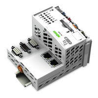
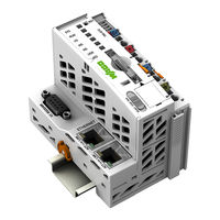
WAGO I/O SYSTEM 750 Manual (468 pages)
750-8208
PFC200 CS 2ETH RS CAN DPM
PLC - Controller PFC200
Brand: WAGO
|
Category: I/O Systems
|
Size: 9 MB
Table of Contents
-
-
-
Legal Bases19
-
-
-
View27
-
Labeling29
-
Connectors30
-
Cage Clamp32
-
Reset Button47
-
Device Data50
-
System Data50
-
Power Supply50
-
Clock51
-
Programming51
-
Ethernet51
-
Canopen52
-
Profibus52
-
Approvals54
-
-
-
Network55
-
DHCP Client62
-
DHCP Server62
-
DNS Server64
-
Formatting65
-
Data Backup67
-
-
5 Mounting
72-
Spacing75
-
-
Task N" Group(S)101
-
Hostname" Group104
-
Time Zone" Group117
-
TZ String" Group118
-
Telnet" Group132
-
FTP" Group132
-
FTPS" Group132
-
HTTP" Group132
-
HTTPS" Group133
-
I/O-CHECK" Group133
-
CODESYS 2" Group135
-
Openvpn" Group147
-
Ipsec" Group147
-
Networking" Menu163
-
Firewall" Menu170
-
Clock" Menu178
-
SNMP" Menu198
-
Network Tab205
-
Protocol Tab207
-
Status Tab208
-
-
Creating Tasks223
-
Cyclic Tasks226
-
System Events231
-
Process Images237
-
Program Memory250
-
Remanent Memory253
-
-
General262
-
Features262
-
Configuration263
-
MODBUS Settings264
-
Data Exchange268
-
Process Image269
-
Flag Area270
-
MODBUS Registers271
-
MODBUS Mapping271
-
MODBUS Watchdog280
-
Diagnostics288
-
-
-
Object Directory291
-
Data Exchange298
-
Maximum Indices303
-
Adding Slaves308
-
Busdiag.lib324
-
-
-
12 Diagnostics
374 -
13 Service
390 -
14 Removal
395 -
15 Appendix
397-
-
Process Data400
-
-
-
Process Data403
-
-
-
Process Data404
-
-
Counter Modules410
-
RTC Module418
-
LON ® FTT Module421
-
System Modules426
-
Syslibcom.lib428
-
Syslibfile.lib428
-
Syslibrtc.lib430
-
Busdiag.lib431
-
Mod_Com.lib431
-
Sercomm.lib431
-
Wagolibled.lib449
-
Wagolibssl.lib450
-
Wago_Dpm_01.Lib453
Advertisement

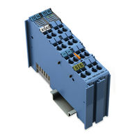
WAGO I/O SYSTEM 750 Manual (296 pages)
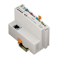
3-Phase Power Measurement Module
Brand: WAGO
|
Category: Control Unit
|
Size: 18 MB
Table of Contents
-
-
Copyright10
-
Symbols11
-
Legal Bases13
-
Disposal14
-
View25
-
Connectors26
-
Approvals44
-
Output Data63
-
Input Data65
-
Mounting88
-
Shielding94
-
General94
-
Accuracy99
-
Measuring Power114
-
Commissioning165
-
Start" Ribbon168
-
Status Bar169
-
Settings" Dialog170
-
I/O Module" Tab177
-
Energy" Tab180
-
I/O Module" Tab184
-
Energy" Tab191
-
Overview" View195
-
Power" View198
-
Energies" View199
-
Harmonics" View200
-
I/O Module" Tab204
-
Energy" Tab210
-
Overview" View213
-
Harmonics" View214
-
I/O Module" Tab218
-
Energy" Tab225
-
Overview" View229
-
Power" View232
-
Energies" View233
-
Harmonics" View234
-
I/O Module" Tab238
-
Energy" Tab244
-
Overview" View248
-
Power" View251
-
Energies" View252
-
Harmonics" View253
-
Diagnostics257
-
LED Diagnostics258
-
Firmware Update260
-
Serial Number262
-
Appendix262
-
Snapshot263
-
Factory Settings269

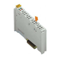
WAGO I/O SYSTEM 750 Manual (260 pages)
Brand: WAGO
|
Category: I/O Systems
|
Size: 4 MB
Table of Contents
-
-
Symbols12
-
Legal Bases15
-
Overview22
-
Properties25
-
View25
-
Labeling27
-
Wiring Level28
-
Connectors28
-
Reset Button38
-
System Data41
-
Power Supply42
-
Programming44
-
Local Bus44
-
Clock44
-
Ethernet45
-
Approvals47
-
Functions54
-
Network54
-
Routing64
-
DHCP-Client68
-
DHCP Server68
-
DNS Server70
-
Formatting73
-
Data Backup75
-
Mounting81
-
Spacing86
-
Connecting89
-
Grounding98
-
Shielding100
-
General100
-
Fieldbus Cables100
-
Commissioning103
-
Shutdown/Restart116
-
Warm Start Reset117
-
Cold Start Reset117
-
Software Reset117
-
Controller Reset117
-
Configuration119
-
Network Tab132
-
PLC Tab134
-
Status Tab135
-
General Notes136
-
Remanent Memory138
-
Modbus139
-
C Led140
-
A Led140
-
Diagnostics140
-
Sys Led141
-
Run Led142
-
I/O Led144
-
Ms Led145
-
Lnk Led146
-
Act Led146
-
Service157
-
Firmware Changes159
-
Removal162
-
Removing Devices162
-
Disposal163
-
Packaging163
-
Appendix165
-
Information" Tab166
-
Routing" Page182
-
Fieldbus" Tab219
-
Security" Tab225
-
Diagnostic" Tab240
-
Counter Modules250
-
CAN Gateway252
Advertisement
WAGO I/O SYSTEM 750 Manual (290 pages)
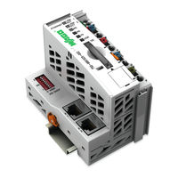
Modular I/O-System, Programmable Fieldbus Controller for Telecontrol Applications
Brand: WAGO
|
Category: I/O Systems
|
Size: 2 MB
Table of Contents
-
-
Symbols11
-
Scope14
-
Abbreviation14
-
-
Spacing26
-
Power Supply32
-
Isolation32
-
Connection33
-
Alignment34
-
Field Supply36
-
Connection36
-
Fusing37
-
Grounding43
-
General46

WAGO I/O SYSTEM 750 Manual (52 pages)
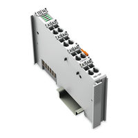
2DO 24V DC 0.5A/ diagnostics 2-Channel Digital Output; 24 V DC; Short-circuit protected; high-side switching; with diagnostics
Brand: WAGO
|
Category: I/O Systems
|
Size: 3 MB
Table of Contents
-
Symbols6
-
Disposal10
-
View17
-
Connectors18
-
Cage Clamp21
-
Device Data24
-
Power Supply24
-
Outputs24
-
Connection25
WAGO I/O SYSTEM 750 Quickstart Reference (54 pages)
ETHERNET Programmable Fieldbus, 10/100 Mbit/s; digital and analog signals
Brand: WAGO
|
Category: I/O Systems
|
Size: 4 MB
Table of Contents
-
-
-
-
Open Project31
WAGO I/O SYSTEM 750 Manual (50 pages)
8DO 24V DC 0.5A, diagnostics 8-Channel Digital Output; 24 VDC; short-circuit protected; high-side switching; with diagnostics
Brand: WAGO
|
Category: I/O Systems
|
Size: 3 MB
Table of Contents
-
Symbols6
-
Disposal10
-
View18
-
Connectors19
-
Device Data25
-
Power Supply25
-
Outputs25

WAGO I/O SYSTEM 750 Product Manual (36 pages)
Controller PFC100; 2nd Generation; 2 x EHTHERNET, RS-232/485
Brand: WAGO
|
Category: Controller
|
Size: 4 MB
Table of Contents
-
-
Overview5
-
View7
-
Indicators11
-
Reset Button13
-
Functions14
-
Planning17
-
Accessories20
-
Diagnostics22
-
Service26
-
Appendix27
WAGO I/O SYSTEM 750 Product Manual (32 pages)
Controller PFC100; 2nd Generation; 2 x ETHERNET, RS-232/-485
Brand: WAGO
|
Category: Controller
|
Size: 4 MB
Table of Contents
-
-
Overview5
-
View7
-
Indicators11
-
Reset Button13
-
Functions14
-
Planning15
-
Diagnostics18
-
Service22
-
Appendix23
-
Accessories23

WAGO I/O SYSTEM 750 Product Manual (28 pages)
Controller PFC100; 2nd Generation; 2 x ETHERNET
Brand: WAGO
|
Category: Controller
|
Size: 4 MB
Table of Contents
-
-
Overview5
-
View7
-
Indicators10
-
Reset Button12
-
Functions14
-
Planning15
-
Diagnostics16
-
Service20
-
Appendix21
-
Accessories21

WAGO I/O SYSTEM 750 Manual (36 pages)
Fieldbus Independent I/O Modules DALI/DSI Master Module
Brand: WAGO
|
Category: I/O Systems
|
Size: 0 MB
Table of Contents
-
2 O Modules
10-
View10
-
Description11
-
Process Data14
-
Input Data16
-
Output Data16
WAGO I/O SYSTEM 750 Manual (24 pages)
Fieldbus Independent I/O Modules 2 AO 0-20 mA EEx i
Brand: WAGO
|
Category: I/O Systems
|
Size: 0 MB
Table of Contents
-
Symbols5
-
Scope6
-
View7
-
Foreword13
-
Divisions13
-
Divisions17
-
For Europe19
-
For America20

WAGO I/O SYSTEM 750 Quick Start Manual (18 pages)
Fieldbus Independent I/O Modules, Bluetooth RF Transceiver
Brand: WAGO
|
Category: I/O Systems
|
Size: 1 MB
Table of Contents
WAGO I/O SYSTEM 750 Manual (12 pages)
Fieldbus Independent I/O Modules
Brand: WAGO
|
Category: I/O Systems
|
Size: 0 MB
Table of Contents

WAGO I/O SYSTEM 750 Manual (12 pages)
Fieldbus Independent I/O Modules
Brand: WAGO
|
Category: I/O Systems
|
Size: 0 MB
Table of Contents

WAGO I/O SYSTEM 750 Manual (10 pages)
Fieldbus Independent I/O Modules 4 DI AC/DC 42 V 20 ms
Brand: WAGO
|
Category: I/O Systems
|
Size: 0 MB
Table of Contents
Advertisement