Sign In
Upload
Manuals
Brands
WAGO Manuals
I/O Systems
I/O SYSTEM 750 750-833
WAGO I/O SYSTEM 750 750-833 Manuals
Manuals and User Guides for WAGO I/O SYSTEM 750 750-833. We have
1
WAGO I/O SYSTEM 750 750-833 manual available for free PDF download: Manual
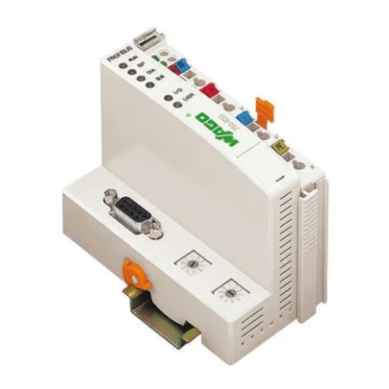
WAGO I/O SYSTEM 750 750-833 Manual (240 pages)
Modular I/O-System PROFIBUS DP/V1, Programmable Field Bus Controller
Brand:
WAGO
| Category:
I/O Systems
| Size: 3.06 MB
Table of Contents
Table of Contents
3
1 Important Notes
9
Legal Principles
9
Copyright
9
Personnel Qualification
9
Conforming Use of Series 750
10
Technical Condition of the Devices
10
Standards and Regulations for Operating the 750 Series
11
Symbols
12
Safety Information
13
Font Conventions
14
Number Notation
14
Scope
15
Abbreviation
15
2 The WAGO-I/O-SYSTEM 750
16
System Description
16
Technical Data
17
Manufacturing Number
23
Component Update
24
Storage, Assembly and Transport
24
Mechanical Setup
25
Installation Position
25
Total Expansion
25
Assembly Onto Carrier Rail
26
Carrier Rail Properties
26
WAGO DIN Rail
27
Spacing
27
Plugging and Removal of the Components
28
Assembly Sequence
29
Internal Bus/Data Contacts
30
Power Contacts
31
Wire Connection
32
Power Supply
33
Isolation
33
System Supply
34
Connection
34
Alignment
35
Field Supply
37
Connection
37
Fusing
38
Supplementary Power Supply Regulations
41
Supply Example
42
Power Supply Unit
43
Grounding
44
Grounding the DIN Rail
44
Framework Assembly
44
Insulated Assembly
44
Grounding Function
45
Grounding Protection
46
Shielding (Screening)
47
General
47
Bus Conductors
47
Signal Conductors
47
WAGO Shield (Screen) Connecting System
48
Assembly Guidelines/Standards
48
3 Programmable Field Bus Controller 750-833
49
Description
49
Hardware
51
View
51
Device Supply
52
Field Bus Connection
53
Display Elements
54
Station Address
55
Configuration and Programming Interface
56
Operating Mode Switch
57
Operating System
58
Run-Up
58
PFC Cycle
59
Process Image
61
Local Process Image
61
Allocation of the Input and Output Data
62
Process Data Structure for PROFIBUS-DP
64
Data Exchange
64
Memory Areas
64
Addressing
67
I/O Module Data
67
Field Bus Variables
68
Flags
68
Calculate Addresses
68
Example for Absolute Addresses
69
Programming of the PFC with WAGO-I/O-PRO
70
PROFIBUS Library for WAGO-I/O-PRO
70
IEC 61131-3 Program Transfer
71
Transmission Via the Serial Interface
71
Transmission Via the Field Bus
73
Byte Process Image Interface
73
MSAC2 Interface
74
Configuration
76
Configuration of the I/O Modules
76
Configuration of the Field Bus Variables
77
GSD Files
78
Identification Bytes
79
Bus Controller Modules
82
I/O Modules
82
Example
83
Parameterization of the Controllers
85
Configuration and Parameterization of the Modules
88
Process Data Channel of the Bus Controller
88
Parameterization of I/O Modules
89
Diagnostics
90
Stations Status 1 to 3
91
PROFIBUS DP Master Address
91
Manufacturer Identification
91
Identification Based Diagnostics
91
Device Status
92
Internal Status Messages and Arguments
93
Internal Bus Status Messages and Arguments
93
PROFIBUS DP Status Messages and Arguments
94
PFC-RTS Status Messages and Arguments
94
Channel Based Diagnostics
95
Fault Types of I/O Modules with Diagnostics Capability
97
I/O Modules Fault Cases
98
Parameterization Status Profisafe
100
Profisafe Parameterization Fault
100
Acyclic Communication According to DP/V1
101
Data Areas
103
Field Bus Coupler, Slots 0 and 1
104
Complex I/O Modules, Slots 1
105
Binary I/O Modules, Slots 1
105
LED Signaling
109
Blink Code
109
Field Bus Status
110
Fault Message Via Blink Code of the BUS LED
111
Node Status
112
Fault Message Via Blink Code of the I/O LED
114
Supply Voltage Status
118
Fault Behavior
119
Field Bus Failure
119
Internal Bus Fault
119
Technical Data
120
4 Field Bus Communication
122
Profibus
122
Description
122
Wiring
123
5 O Modules
126
Overview
126
Digital Input Modules
126
Digital Output Modules
128
Analog Input Modules
129
Analog Output Modules
131
Special Modules
132
System Modules
134
Design of the Process Data for PROFIBUS-DP
135
DI I/O Modules
135
DI I/O Modules with Diagnostics
135
DI I/O Modules
136
DO I/O Modules
136
Wago-I/O-System
136
DO I/O Modules with Diagnostics
137
DO I/O Modules
137
DO I/O Module with Diagnostics
137
DO I/O Modules
138
DO I/O Module with Diagnostics
138
Power Supply Modules
138
AI I/O Modules
139
AI I/O Modules
140
AO I/O Modules
141
AO I/O Modules
142
Counter Modules
143
PWM Module
144
Stepper Controller
144
SSI Encoder Interface
145
Incremental Encoder Interfaces
146
Digital Impulse Interface
146
Serial Interface
147
Data Exchange Module
148
DALI/DSI Master
149
AS Interface Master
149
Profisafe I/O Modules
150
PROFIBUS Identification Bytes of I/O Modules
151
Binary Input Modules
151
Binary Output Modules
152
Supply Modules
152
Analog Input Modules
153
Analog Output Modules
153
Special Modules
154
Field Bus Variables
155
PFC Input Variables in the Field Bus Output Process Image
155
PFC Output Variables in the Field Bus Input Process Image
158
Configuration and Parameterization of the I/O Modules
161
Digital I/O Modules
161
DI I/O Modules
162
DI I/O Modules with 1 Bit Diagnostics Per Channel
163
DI I/O Modules
165
DI I/O Modules
166
DI I/O Modules
167
DO I/O Modules
168
(1) DO I/O Modules with 1 Bit Diagnostics Per Channel
169
DO I/O Module with 2 Bit Diagnostics Per Channel
171
DO I/O Modules
173
DO I/O Modules with 1 Bit Diagnostics Per Channel
174
DO I/O Modules
176
DO I/O Modules with 1 Bit Diagnostics Per Channel
178
DO I/O Module
180
DI/DO I/O Modules with 1 Bit Diagnostics Per Channel
181
Power Supply Modules with Diagnostics
183
Analog I/O Modules
185
AI I/O Modules
185
AI I/O Modules
187
AO I/O Modules
188
AO I/O Modules
190
Digital Special Modules
192
Counter Modules
192
PWM Module
193
Stepper Controller
194
Distance and Angle Measurement Modules
195
SSI Encoder Interface
195
Incremental Encoder Interface
196
Digital Impulse Interface
197
Serial Interfaces
198
Data Exchange Module
199
ENOCEAN Receiver Module
200
DALI/DSI Master
201
AS Interface Master
202
Profisafe Modules
204
Acyclic Communication According to DP/V1
206
DI I/O Modules
206
DI I/O Modules with 1 Bit Diagnostics Per Channel
206
DI I/O Modules
207
DO I/O Modules
208
DO I/O Modules with 1 or 2 Bit Diagnostics Per Channel
208
DO I/O Modules with 1 Bit Diagnostics Per Channel
209
DO I/O Modules
210
DO I/O Modules with 1 Bit Diagnostics Per Channel
211
DO I/O Modules
212
DI/DO I/O Modules with 1 Bit Diagnostics Per Channel
213
Supply Module with Diagnostics
213
AI I/O Modules
214
AI I/O Modules
215
AO I/O Modules
217
AO I/O Modules
218
Counter Module 750-404
220
Counter Module 750-638 and PWM Module 750-511
221
SSI Interface
222
Incremental Encoder Interfaces and Serial Interfaces
222
Digital Impulse Interface
223
Serial Interfaces and Data Exchange Module
223
DALI/DSI Master
224
AS Interface Master
224
Wago-I/O-System
224
Profisafe I/O Modules
225
6 Use in Hazardous Environments
226
Foreword
226
Protective Measures
226
Classification Meeting CENELEC and IEC
226
Divisions
226
Explosion Protection Group
228
Unit Categories
229
Temperature Classes
230
Types of Ignition Protection
231
Classifications Meeting the NEC 500
232
Divisions
232
Explosion Protection Groups
232
Temperature Classes
233
Identification
234
For Europe
234
For America
235
Installation Regulations
236
7 List of Literature
238
8 Index
239
Advertisement
Advertisement
Related Products
WAGO I/O SYSTEM 750 750-671
WAGO I/O SYSTEM 750 750-635
WAGO I/O-SYSTEM 750 753-501
WAGO I/O SYSTEM 750 750-641
WAGO I/O SYSTEM 750 750-421
WAGO I/O System 750 750-460
WAGO I/O System 750 750-622
WAGO I/O System 750 750-483
WAGO I/O System 750/753
WAGO 750-630/000-012
WAGO Categories
I/O Systems
Control Unit
Power Supply
Switch
Controller
More WAGO Manuals
Login
Sign In
OR
Sign in with Facebook
Sign in with Google
Upload manual
Upload from disk
Upload from URL