WAGO I/O System 750 Manual
2do 24v dc 0.5a/ diagnostics 2-channel digital output; 24 v dc; short-circuit protected; high-side switching; with diagnostics
Hide thumbs
Also See for I/O System 750:
- Manual (468 pages) ,
- Quickstart reference (54 pages) ,
- Product manual (28 pages)

Subscribe to Our Youtube Channel
Related Manuals for WAGO I/O System 750


Summary of Contents for WAGO I/O System 750
- Page 1 Manual WAGO I/O System 750 753-506 2DO 24V DC 0.5A/ diagnostics 2-Channel Digital Output; 24 V DC; Short-circuit protected; high-side switching; with diagnostics Version 1.3.1 Public...
- Page 2 We wish to point out that the software and hardware terms as well as the trademarks of companies used and/or mentioned in the present manual are generally protected by trademark or patent. WAGO is a registered trademark of WAGO Verwaltungsgesellschaft mbH. Manual Version 1.3.1...
-
Page 3: Table Of Contents
WAGO I/O System 750 Table of Contents 753-506 2DO 24V DC 0.5A/ diagnostics Table of Contents Notes about this Documentation ............. 5 Validity of this Documentation..............5 Copyright ....................5 Symbols ....................6 Number Notation ..................8 Font Conventions ................... 8 Important Notes .................. - Page 4 Table of Contents WAGO I/O System 750 753-506 2DO 24V DC 0.5A/ diagnostics Connection Examples ................37 6.2.1 2-Conductor Connection, Ungrounded ..........37 6.2.2 2-Conductor Connection, Grounded ..........37 6.2.3 3-Conductor Connection, Ungrounded ..........38 6.2.4 3-Conductor Connection, Grounded ..........38 Use in Hazardous Environments ............
-
Page 5: Notes About This Documentation
Consider power layout of the WAGO I/O System 750! In addition to these operating instructions, you will also need the manual for the used fieldbus coupler or controller, which can be downloaded at www.wago.com. There, you can obtain important information including information on electrical isolation, system power and supply specifications. -
Page 6: Symbols
Notes about this Documentation WAGO I/O System 750 753-506 2DO 24V DC 0.5A/ diagnostics Symbols Personal Injury! Indicates a high-risk, imminently hazardous situation which, if not avoided, will result in death or serious injury. Personal Injury Caused by Electric Current! Indicates a high-risk, imminently hazardous situation which, if not avoided, will result in death or serious injury. - Page 7 WAGO I/O System 750 Notes about this Documentation 753-506 2DO 24V DC 0.5A/ diagnostics Additional Information: Refers to additional information which is not an integral part of this documentation (e.g., the Internet). Manual Version 1.3.1 Public...
-
Page 8: Number Notation
Notes about this Documentation WAGO I/O System 750 753-506 2DO 24V DC 0.5A/ diagnostics Number Notation Table 1: Number Notation Number Code Example Note Decimal Normal notation Hexadecimal 0x64 C notation Binary '100' In quotation marks, nibble separated '0110.0100' with dots (.) -
Page 9: Important Notes
2.1.1 Subject to Changes WAGO Kontakttechnik GmbH & Co. KG reserves the right to provide for any alterations or modifications. WAGO Kontakttechnik GmbH & Co. KG owns all rights arising from the granting of patents or from the legal protection of utility patents. -
Page 10: Technical Condition Of Specified Devices
The implementation of safety functions such as EMERGENCY STOP or safety door monitoring must only be performed by the F I/O modules within the modular WAGO I/O System 750. Only these safe F I/O modules ensure functional safety in accordance with the latest international standards. WAGO's interference-free output modules can be controlled by the safety function. -
Page 11: 2.1.4.1.2 Packaging
WAGO I/O System 750 Important Notes 753-506 2DO 24V DC 0.5A/ diagnostics Environmentally friendly disposal benefits health and protects the environment from harmful substances in electrical and electronic equipment. • Observe national and local regulations for the disposal of electrical and electronic equipment. -
Page 12: Safety Advice (Precautions)
Important Notes WAGO I/O System 750 753-506 2DO 24V DC 0.5A/ diagnostics Safety Advice (Precautions) For installing and operating purposes of the relevant device to your system the following safety precautions shall be observed: Do not work on devices while energized! All power sources to the device shall be switched off prior to performing any installation, repair or maintenance work. - Page 13 WAGO I/O System 750 Important Notes 753-506 2DO 24V DC 0.5A/ diagnostics Ensure proper contact with the DIN-rail! Proper electrical contact between the DIN-rail and device is necessary to maintain the EMC characteristics and function of the device. Replace defective or damaged devices! Replace defective or damaged device/module (e.g., in the event of deformed...
- Page 14 Important Notes WAGO I/O System 750 753-506 2DO 24V DC 0.5A/ diagnostics Avoid electrostatic discharge! The devices are equipped with electronic components that may be destroyed by electrostatic discharge when touched. Please observe the safety precautions against electrostatic discharge per DIN EN 61340-5-1/-3. When handling the devices, please ensure that environmental factors (personnel, work space and packaging) are properly grounded.
-
Page 15: Device Description
WAGO I/O System 750 Device Description 753-506 2DO 24V DC 0.5A/ diagnostics Device Description The 753-506 (2DO 24V DC 0.5A/ diagnostics) Digital Output Module transmits binary control signals from the automation device to the connected actuators (e.g., solenoid valves, contactors, transmitters or other electrical loads). - Page 16 Device Description WAGO I/O System 750 753-506 2DO 24V DC 0.5A/ diagnostics Do not exceed maximum values via power contacts! The maximum current that can flow through the power jumper contacts is 10 A. The power jumper contacts can be damaged and the permissible operating temperature can be exceeded by higher current values.
-
Page 17: View
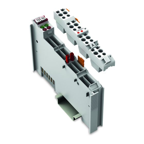
WAGO I/O System 750 Device Description 753-506 2DO 24V DC 0.5A/ diagnostics View Depiction of the I/O module with 753-110 Plug! Information on this pluggable connection pertains to the 753-110 Plug, which is not included with the I/O module. Figure 1: View Table 3: Legend for Figure “View”... -
Page 18: Connectors
Device Description WAGO I/O System 750 753-506 2DO 24V DC 0.5A/ diagnostics Connectors 3.2.1 Data Contacts/Local Bus Communication between the fieldbus coupler/controller and the I/O modules as well as the system supply of the I/O modules is carried out via the local bus. The contacting for the local bus consists of 6 data contacts, which are available as self-cleaning gold spring contacts. -
Page 19: Power Jumper Contacts/Field Supply
WAGO I/O System 750 Device Description 753-506 2DO 24V DC 0.5A/ diagnostics 3.2.2 Power Jumper Contacts/Field Supply Risk of injury due to sharp-edged blade contacts! The blade contacts are sharp-edged. Handle the I/O module carefully to prevent injury. Do not touch the blade contacts. - Page 20 Device Description WAGO I/O System 750 753-506 2DO 24V DC 0.5A/ diagnostics Do not exceed maximum values via power contacts! The maximum current that can flow through the power jumper contacts is 10 A. The power jumper contacts can be damaged and the permissible operating temperature can be exceeded by higher current values.
-
Page 21: Cage Clamp
WAGO I/O System 750 Device Description 753-506 2DO 24V DC 0.5A/ diagnostics 3.2.3 CAGE CLAMP Connectors ® Depiction of the I/O module with 753-110 Plug! Information on this pluggable connection pertains to the 753-110 Plug, which is not included with the I/O module. -
Page 22: Display Elements
Device Description WAGO I/O System 750 753-506 2DO 24V DC 0.5A/ diagnostics Display Elements Figure 5: Display Elements Table 6: Legend for Figure “Display Elements” Status DO 1 Green Off Green Off Off Green Green Off Error DO 1 Status from PLC... -
Page 23: Schematic Diagram
WAGO I/O System 750 Device Description 753-506 2DO 24V DC 0.5A/ diagnostics Schematic Diagram Figure 6: Schematic Diagram Manual Version 1.3.1 Public... -
Page 24: Technical Data
Device Description WAGO I/O System 750 753-506 2DO 24V DC 0.5A/ diagnostics Technical Data 3.5.1 Device Data Table 7: Technical Data ‒ Device Width 12 mm Depth (from upper edge of 35 DIN rail) 62.6 mm Height 100 mm Weight 54 g 3.5.2... -
Page 25: Connection
WAGO I/O System 750 Device Description 753-506 2DO 24V DC 0.5A/ diagnostics 3.5.5 Connection Table 11: Technical Data – Field Wiring Connection technology CAGE CLAMP ® Conductor cross-section 0.08 mm² ... 2.5 mm² / AWG 28 … 14 Strip length 9 mm ... -
Page 26: Approvals
Approvals More information about approvals. Detailed references to the approvals are listed in the document “Overview on WAGO I/O System 750 approvals”, which you can find via the internet under: www.wago.com DOWNLOADS Documentation System Description. The following approvals have been granted to the basic version of 753-506 I/O... -
Page 27: Standards And Guidelines
WAGO I/O System 750 Device Description 753-506 2DO 24V DC 0.5A/ diagnostics Standards and Guidelines 753-506 I/O modules meet the following requirements on emission and immunity of interference: EMC CE-Emission of interference EN 61000-6-4 EMC CE-Immunity to interference EN 61000-6-2 Manual Version 1.3.1... -
Page 28: Process Image
Process Image WAGO I/O System 750 753-506 2DO 24V DC 0.5A/ diagnostics Process Image Table 15: Output Bits Bit 3 Bit 2 Bit 1 Bit 0 DO 2 DO 1 DO 1 Signal state DO 1 – Digital output channel 1 DO 2 Signal state DO 2 –... -
Page 29: Mounting
Always plug a bus end module (e.g. 750-600) onto the end of the fieldbus node! You must always use a bus end module at all fieldbus nodes with WAGO I/O System 750 fieldbus couplers or controllers to guarantee proper data transfer. -
Page 30: Inserting And Removing Devices
Mounting WAGO I/O System 750 753-506 2DO 24V DC 0.5A/ diagnostics Inserting and Removing Devices Do not work when devices are energized! High voltage can cause electric shock or burns. Switch off all power to the device prior to performing any installation, repair or maintenance work. -
Page 31: Removing The I/O Module
WAGO I/O System 750 Mounting 753-506 2DO 24V DC 0.5A/ diagnostics 5.2.2 Removing the I/O Module Note Remove pluggable wiring! Before removing a 753 Series I/O Module from the node, you must first remove the plug (pluggable wiring) from the I/O module (see section “Plug Removal”)! -
Page 32: I/O Modules With Pluggable Wiring Level (Series 753)
Mounting WAGO I/O System 750 753-506 2DO 24V DC 0.5A/ diagnostics I/O Modules with Pluggable Wiring Level (Series 753) For wiring, a plug is plugged into the bottom of the module of all 753 Series I/O modules. The plug can be completely removed together with the wiring, simplifying replacement of defective modules from the assembly. -
Page 33: Coding
WAGO I/O System 750 Mounting 753-506 2DO 24V DC 0.5A/ diagnostics Figure 12: Attachment of Cable Binders 5.3.1 Coding Coding using small plastic pins and sockets facilitates mating of the I/O module with the appropriate plug. Insert the pin into the socket. -
Page 34: Figure 15: Plugging The Plug Into Place
Mounting WAGO I/O System 750 753-506 2DO 24V DC 0.5A/ diagnostics Figure 15: Plugging the Plug into Place When the plug is removed the sockets remain in the I/O module. The coded plug can only fit in the corresponding coded I/O module (see figures below). -
Page 35: Plug Removal
WAGO I/O System 750 Mounting 753-506 2DO 24V DC 0.5A/ diagnostics 5.3.2 Plug Removal Remove the plug from the I/O module by pulling the orange pull tab on the plug toward the top of the I/O module. Figure 17: Pulling the Pull Tab The plug detaches from the I/O module. -
Page 36: Connect Devices
Do not connect more than one conductor at one single connection! If more than one conductor must be routed to one connection, these must be connected in an up-circuit wiring assembly, for example using WAGO feed- through terminals. For opening the CAGE CLAMP insert the actuating tool into the opening ®... -
Page 37: Connection Examples
WAGO I/O System 750 Connect Devices 753-506 2DO 24V DC 0.5A/ diagnostics Connection Examples Depiction of the I/O module with 753-110 Plug! Information on this pluggable connection pertains to the 753-110 Plug, which is not included with the I/O module. -
Page 38: 3-Conductor Connection, Ungrounded
Connect Devices WAGO I/O System 750 753-506 2DO 24V DC 0.5A/ diagnostics 6.2.3 3-Conductor Connection, Ungrounded Figure 23: Connecting Diagram, 3-Conductor Connection, Ungrounded 6.2.4 3-Conductor Connection, Grounded Figure 24: Connecting Diagram, 3-Conductor Connection, Grounded Manual Version 1.3.1 Public... -
Page 39: Use In Hazardous Environments
Use in Hazardous Environments 753-506 2DO 24V DC 0.5A/ diagnostics Use in Hazardous Environments The WAGO I/O System 750 (electrical equipment) is designed for use in Zone 2 hazardous areas and shall be used in accordance with the marking and installation regulations. -
Page 40: Marking Configuration Examples
Use in Hazardous Environments WAGO I/O System 750 753-506 2DO 24V DC 0.5A/ diagnostics Marking Configuration Examples 7.1.1 Marking for Europe According to ATEX and IECEx Figure 25: Marking Example per ATEX and IECEx Figure 26: Text Detail – Marking Example per ATEX and IECEx Manual Version 1.3.1... -
Page 41: Table 17: Description Of The Marking Example Per Atex And Iecex
WAGO I/O System 750 Use in Hazardous Environments 753-506 2DO 24V DC 0.5A/ diagnostics Table 17: Description of the Marking Example per ATEX and IECEx Marking Text Description TUEV 07 ATEX 554086 X Approving authority or certificate numbers IECEx TUN 09.0001 X... -
Page 42: Figure 27: Marking Example Of An Approved I/O Module Ex I Per Atex And
Use in Hazardous Environments WAGO I/O System 750 753-506 2DO 24V DC 0.5A/ diagnostics Figure 27: Marking Example of an Approved I/O Module Ex i per ATEX and IECEx Figure 28: Text Detail – Marking Example of an Approved I/O Module Ex i... -
Page 43: Table 18: Description Of The Marking Example Of An Approved I/O Module Ex I Per Atex And Iecex
WAGO I/O System 750 Use in Hazardous Environments 753-506 2DO 24V DC 0.5A/ diagnostics Table 18: Description of the Marking Example of an Approved I/O Module Ex i per ATEX and IECEx Marking Text Description TUEV 12 ATEX 106032 X... -
Page 44: Marking For The United States Of America (Nec) And Canada (Cec)
Use in Hazardous Environments WAGO I/O System 750 753-506 2DO 24V DC 0.5A/ diagnostics 7.1.2 Marking for the United States of America (NEC) and Canada (CEC) Figure 29: Marking Example According to NEC Figure 30: Text Detail – Marking Example According to NEC 500... -
Page 45: Figure 31: Text Detail - Marking Example For Approved I/O Module Ex I
WAGO I/O System 750 Use in Hazardous Environments 753-506 2DO 24V DC 0.5A/ diagnostics Figure 31: Text Detail – Marking Example for Approved I/O Module Ex i According to NEC 505 Table 20: Description of Marking Example for Approved I/O Module Ex i According to NEC 505... -
Page 46: Figure 33: Text Detail - Marking Example For Approved I/O Module Ex I
Use in Hazardous Environments WAGO I/O System 750 753-506 2DO 24V DC 0.5A/ diagnostics Figure 33: Text Detail – Marking Example for Approved I/O Module Ex i According to CEC 18 attachment J Table 22: Description of Marking Example for Approved I/O Module Ex i According to CEC 18... -
Page 47: Installation Regulations
Special Notes including Explosion Protection The following warning notices are to be posted in the immediately proximity of the WAGO I/O System 750 (hereinafter “product”): WARNING – DO NOT REMOVE OR REPLACE FUSED WHILE ENERGIZED! WARNING – DO NOT DISCONNECT WHILE ENERGIZED! WARNING –... - Page 48 Use in Hazardous Environments WAGO I/O System 750 753-506 2DO 24V DC 0.5A/ diagnostics Explosive atmosphere occurring simultaneously with assembly, installation or repair work must be ruled out. Among other things, these include the following activities • Insertion and removal of components •...
-
Page 49: Special Notes Regarding Ul Hazardous Location
WAGO I/O System 750 Use in Hazardous Environments 753-506 2DO 24V DC 0.5A/ diagnostics 7.2.2 Special Notes Regarding UL Hazardous Location For UL Hazardous Location acc. to UL File E198726, the following additional requirements apply: • Use in Class I, Division 2, Group A, B, C, D or non-hazardous areas only •... -
Page 50: List Of Figures
List of Figures WAGO I/O System 750 753-506 2DO 24V DC 0.5A/ diagnostics List of Figures Figure 1: View ....................17 Figure 2: Data Contacts ..................18 Figure 3: Power Jumper Contacts ..............19 Figure 4: CAGE CLAMP Connectors ..............21 ® Figure 5: Display Elements.................22 Figure 6: Schematic Diagram ................23... -
Page 51: List Of Tables
WAGO I/O System 750 List of Tables 753-506 2DO 24V DC 0.5A/ diagnostics List of Tables Table 1: Number Notation ................... 8 Table 2: Font Conventions .................. 8 Table 3: Legend for Figure “View” ..............17 Table 4: Legend for Figure “Power Jumper Contacts” ........19 Table 5: Legend for Figure “CAGE CLAMP... - Page 52 WAGO Kontakttechnik GmbH & Co. KG Postfach 2880 • D - 32385 Minden Hansastraße 27 • D - 32423 Minden Phone: +49 571 887 – 0 Fax: +49 571 887 – 844169 E-Mail: info@wago.com Internet: www.wago.com...
Need help?
Do you have a question about the I/O System 750 and is the answer not in the manual?
Questions and answers