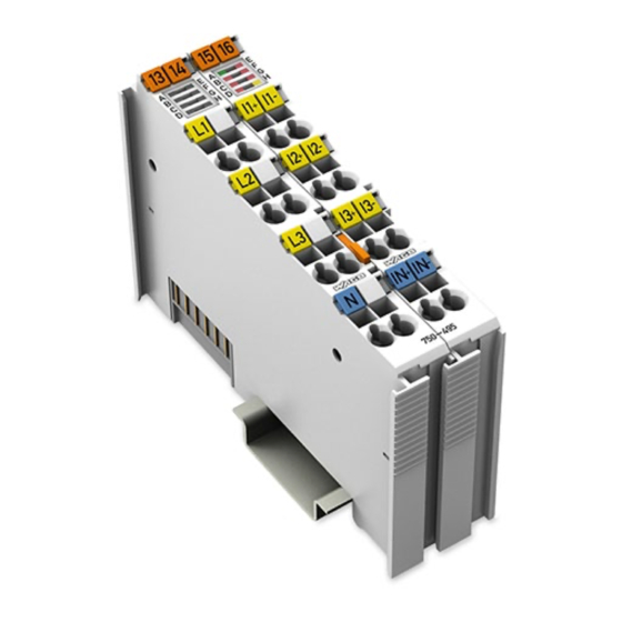
Fieldbus independent i/o modules, module bus extension coupler (32 pages)
Summary of Contents for WAGO I/O System 750
Page 1
Manual WAGO I/O System 750/753 750-495 3-Phase Power Measurement Module 3-Phase Power Measurement Version 1.3.0...
Page 2
We wish to point out that the software and hardware terms as well as the trademarks of companies used and/or mentioned in the present manual are generally protected by trademark or patent. WAGO is a registered trademark of WAGO Verwaltungsgesellschaft mbH. Manual Version 1.3.0...
WAGO I/O System 750/753 Table of Contents 750-495 3-Phase Power Measurement Module Table of Contents Notes about this Documentation .............. 9 Validity of this Documentation ..............9 Revision History ..................10 Copyright....................10 Symbols ....................11 Number Notation ..................12 Font Conventions ...................
Page 4
General ..................... 94 7.2.2 Fieldbus Cables................. 94 7.2.3 Shielded Signal Lines ................ 95 7.2.4 WAGO Shield Connecting System ............ 95 Connecting a Conductor to the CAGE CLAMP ........96 ® Current Measurement ................97 7.4.1 Current Measurement Transformers ..........97 7.4.1.1...
WAGO I/O System 750/753 Table of Contents 750-495 3-Phase Power Measurement Module 7.4.2 Rogowski Coils .................. 99 7.4.3 Current Measurement on a Load ............ 101 Voltage Measurement ................102 7.5.1 Voltage Measurement Transformer ..........103 Overview of Supply Networks, Measurement Topologies and Voltages ....................
Page 6
Table of Contents WAGO I/O System 750/753 750-495 3-Phase Power Measurement Module 7.7.4.4 Measuring with the Measurement Topology “4-Wire Wye” (“4-W”) without Voltage Measurement Transformers (VT) ..141 7.7.4.5 Measuring with the Measurement Topology “4-Wire Wye, 2-Phase” (“4-W/2-P”) with Voltage Measurement Transformers (VT) .....................
Page 8
Table of Contents WAGO I/O System 750/753 750-495 3-Phase Power Measurement Module Diagnostics ..................... 257 LED Diagnostics .................. 258 Diagnostics in Dependence on Set Measurement Topology ....259 Firmware Update ..................260 Appendix ....................262 11.1 Serial Number ..................262 11.2...
Consider power layout of the WAGO I/O System 750! In addition to these operating instructions, you will also need the manual for the used fieldbus coupler or controller, which can be downloaded at www.wago.com. There, you can obtain important information including information on electrical isolation, system power and supply specifications.
Manual by third parties that violate pertinent copyright provisions is prohibited. Reproduction, translation, electronic and phototechnical filing/archiving (e.g., photocopying) as well as any amendments require the written consent of WAGO GmbH & Co. KG, Minden, Germany. Non-observance will involve the right to assert damage claims. Manual...
WAGO I/O System 750/753 Notes about this Documentation 750-495 3-Phase Power Measurement Module Symbols Personal Injury! Indicates a high-risk, imminently hazardous situation which, if not avoided, will result in death or serious injury. Personal Injury Caused by Electric Current! Indicates a high-risk, imminently hazardous situation which, if not avoided, will result in death or serious injury.
Notes about this Documentation WAGO I/O System 750/753 750-495 3-Phase Power Measurement Module Additional Information: Refers to additional information which is not an integral part of this documentation (e.g., the Internet). Number Notation Table 3: Number Notation Number Code Example...
2.1.1 Subject to Changes WAGO GmbH & Co. KG reserves the right to provide for any alterations or modifications. WAGO GmbH & Co. KG owns all rights arising from the granting of patents or from the legal protection of utility patents. Third-party products are always mentioned without any reference to patent rights.
These modules contain no parts that can be serviced or repaired by the user. The following actions will result in the exclusion of liability on the part of WAGO GmbH & Co. KG: •...
WAGO I/O System 750/753 Important Notes 750-495 3-Phase Power Measurement Module Environmentally friendly disposal benefits health and protects the environment from harmful substances in electrical and electronic equipment. • Observe national and local regulations for the disposal of electrical and electronic equipment.
Important Notes WAGO I/O System 750/753 750-495 3-Phase Power Measurement Module Safety Advice (Precautions) For installing and operating purposes of the relevant device to your system the following safety precautions shall be observed: Install protection against electric shock! All wiring for the measurement system shall be provided with protection against...
Page 17
WAGO I/O System 750/753 Important Notes 750-495 3-Phase Power Measurement Module Only connect or disconnect lines when power is safely isolated! The lines to the device can carry hazardous voltages and currents. Contact with the lines when live can result in severe injury or death. Therefore, read and observe the following safety rules before you perform work on the device: Disconnect the respective system component from the power supply.
Page 18
Important Notes WAGO I/O System 750/753 750-495 3-Phase Power Measurement Module Ensure safe isolation Safe isolation for neighboring SELV/PELV modules must be maintained. Section 3.6.11 “Insulation to Adjacent I/O Modules per EN/UL 61010-2-201” contains the types of insulation to neighboring modules.
Page 19
WAGO I/O System 750/753 Important Notes 750-495 3-Phase Power Measurement Module Clean only with permitted materials! Clean housing and soiled contacts with propanol. Do not use any contact spray! Do not use any contact spray. The spray may impair contact area functionality in connection with contamination.
Important Notes WAGO I/O System 750/753 750-495 3-Phase Power Measurement Module Statements on North American national differences according to UL 61010-1 Precautions on installing current transformers intended to be installed in panel boards or switchgears - To reduce risk of electric shock, always open or disconnect circuit from power- distribution system (or service) of building before installing or servicing current transformers.
Page 21
WAGO I/O System 750/753 Important Notes 750-495 3-Phase Power Measurement Module Field wiring Due to the potential contact between hazardous live conductors with the output conductors of field-installed energy-monitoring current transformers, these incoming field-installed leads from switchgear units/panel boards shall be reclassified as NFPA 70 and C22.1 Class 1 wiring.
This allows visualization as a four-quadrant display, as has been implemented in the display of the measured values in WAGO-I/O-CHECK, among other things. The voltages of the three phases are connected to CAGE CLAMP connections ®...
Page 23
WAGO I/O System 750/753 Device Description 750-495 3-Phase Power Measurement Module • “Artificial Star Point” (“ASP”): Measurement topology for 3-phase networks and without neutral conductor or grounded phase in which the input impedances of the voltage measurement path comprise an artificial star point in the I/O module that is used for the voltage measurement.
Page 24
The I/O module has no power jumper contacts. Use a power supply module for the field supply to subsequent I/O modules. The 750-495 I/O module can be operated on all fieldbus couplers/controllers of the WAGO I/O System 750/753. Manual Version 1.3.0...
WAGO I/O System 750/753 Device Description 750-495 3-Phase Power Measurement Module View Figure 1: View of 750-495 and 750-495/000-001 (left) and 750-495/000-002 (right) Table 5: Legend for Figure “View” Pos. Description Details See Section Marking possibility with Mini- Status LEDs “Device Description”...
Device Description WAGO I/O System 750/753 750-495 3-Phase Power Measurement Module Connectors 3.2.1 Data Contacts/Local Bus Communication between the fieldbus coupler/controller and the I/O modules as well as the system supply of the I/O modules is carried out via the local bus. The contacting for the local bus consists of 6 data contacts, which are available as self-cleaning gold spring contacts.
WAGO I/O System 750/753 Device Description 750-495 3-Phase Power Measurement Module 3.2.3 CAGE CLAMP ® Connectors The 12 CAGE CLAMP connections are measurement inputs. The current and ® voltage signals of the 3-phase supply network are connected here; see also the section “Connecting Devices.”...
Device Description WAGO I/O System 750/753 750-495 3-Phase Power Measurement Module Figure 4: CAGE CLAMP ® Connectors 750-495/000-002 Table 7: Legend for Figure “CAGE CLAMP ® Connectors 750-495/000-002” Measuring Connector Function Channel Voltage of phase L1 RC1+ Current of phase L1 via ‘Rogowski coil’...
WAGO I/O System 750/753 Device Description 750-495 3-Phase Power Measurement Module Display Elements LED A displays a status message. LEDs B to G display possible error messages. LED H displays information regarding the rotating field. Figure 5: Display Elements The meaning of the indicators is as follows: Table 8: Legend for Figure “Display Elements”...
Device Description WAGO I/O System 750/753 750-495 3-Phase Power Measurement Module Operating Elements The I/O module 750-495 has no operating elements. Schematic Diagram When measuring voltage and power, always observe specifications for measurement topologies, supply networks, voltage levels and voltage measurement transformers.
WAGO I/O System 750/753 Device Description 750-495 3-Phase Power Measurement Module Figure 7: Schematic Diagram for 750-495 and 750-495/000-001 Manual Version 1.3.0...
Device Description WAGO I/O System 750/753 750-495 3-Phase Power Measurement Module Figure 8: Schematic Diagram for 750-495/000-002, Hardware Version 01 Manual Version 1.3.0...
WAGO I/O System 750/753 Device Description 750-495 3-Phase Power Measurement Module Figure 9: Schematic Diagram for 750-495/000-002, Hardware Version 02 or above Manual Version 1.3.0...
Device Description WAGO I/O System 750/753 750-495 3-Phase Power Measurement Module Technical Data 3.6.1 Dimensions and Weight Table 9: Technical Data ‒ Dimensions and Weight Width 24 mm Depth (from upper edge of carrier rail) 60.6 mm Height 100 mm...
Page 35
WAGO I/O System 750/753 Device Description 750-495 3-Phase Power Measurement Module Nominal input current AC max. 750-495 1 A 750-495/000-001 5 A 750-495/000-002 Secondary voltages of Rogowski coils up to 88 mV AC short-time current max. 750-495 - For 1 sec.: 4 A - For 100 sec.: 3 A...
Device Description WAGO I/O System 750/753 750-495 3-Phase Power Measurement Module 3.6.4 Measured Values Table 12: Technical Data – Measured Values Measurement method RMS value calculation (true RMS) for voltages and currents, measured value acquisition at 8 kHz, synchronous on...
WAGO I/O System 750/753 Device Description 750-495 3-Phase Power Measurement Module Table 12: Technical Data – Measured Values Settling times: Voltages and currents 620 ms at 100 % (1300 ms after power on) Active power and apparent power 415 ms at 60 %...
Insulation up to Hardware Version 02 The information on the hardware version of the I/O module can be found on the I/O module (see Appendix, Section “Serial Number”) or in WAGO I/O-CHECK (see Section “Commissioning” > … > “‘Information’ View”).
Insulation for Hardware Version 03 or above The information on the hardware version of the I/O module can be found on the I/O module (see Appendix, Section “Serial Number”) or in WAGO I/O-CHECK (see Section “Commissioning” > … > “‘Information’ View”).
Device Description WAGO I/O System 750/753 750-495 3-Phase Power Measurement Module 3.6.10.2 Insulation for System Voltages up to 600 V Table 21: Technical Data – Insulation for System Voltages up to 600 V Insulation type per EN/UL 61010-2-201 and EN/UL 61010-2-030...
WAGO I/O System 750/753 Device Description 750-495 3-Phase Power Measurement Module 3.6.11 Insulation to Adjacent I/O Modules per EN/UL 61010-2-201 Table 22: Technical Data – Insulation to Adjacent I/O Modules per EN/UL 61010-2-201 Adjacent I/O modules with - 8 connections and housing width of 12 mm...
This ship approval is only applicable from HW 02 / SW 02! The information on the hardware version of the I/O module can be found on the I/O module (see Appendix, Section “Serial Number”) or in WAGO I/O-CHECK (see Section “Commissioning” > … > “‘Information’ View”).
750-495 3-Phase Power Measurement Module Standards and Guidelines 750-495 I/O modules meet the following standards and guidelines: For current approvals, please go to: www.wago.com/<Item number>. The 3-Phase Power Measurement Module (750-495) complies with the Low Voltage Directive through application of the following standards:...
Function Description WAGO I/O System 750/753 750-495 3-Phase Power Measurement Module Function Description Measurement Principle The 3-Phase Power Measurement Module uses 7 A/D converters to capture the current and voltage values of all 3 phases and the current in the neutral conductor according to the schematic illustrations in the section “Schematic...
WAGO I/O System 750/753 Function Description 750-495 3-Phase Power Measurement Module Table 25: Measured Values 3-Wire 4-Wire Artificial 4-Wire Measured value Wye/ Wye, Star Delta 2-Phase Point Voltage RMS voltage, L1-N RMS voltage, L2-N RMS voltage, L3-N Max. RMS voltage, L1-N Max.
Page 48
Function Description WAGO I/O System 750/753 750-495 3-Phase Power Measurement Module Table 25: Measured Values 3-Wire 4-Wire Artificial 4-Wire Measured value Wye/ Wye, Star Delta 2-Phase Point Peak value, current, L2 Peak value, current, L3 RMS current, N Power Effective power, L1...
Page 49
WAGO I/O System 750/753 Function Description 750-495 3-Phase Power Measurement Module Table 25: Measured Values 3-Wire 4-Wire Artificial 4-Wire Measured value Wye/ Wye, Star Delta 2-Phase Point Energy Active energy, L1 Active energy, L2 Active energy, L3 Active energy import, L1...
Page 50
Function Description WAGO I/O System 750/753 750-495 3-Phase Power Measurement Module Table 25: Measured Values 3-Wire 4-Wire Artificial 4-Wire Measured value Wye/ Wye, Star Delta 2-Phase Point Minimum line frequency, L3 Phase angle phi Phase angle phi, L1 Phase angle phi, L2...
Page 51
Fundamental component, voltage, Harmonic factor of voltage, L3, 1. … 40th upper harmonic Distortion, voltage, L3 Only values displayed in WAGO-I/O-CHECK and in CODESYS function blocks. Not in the process image! Active power, total Reactive power, total Apparent power, total...
RMS values. The time interval for which the mean value should be calculated can be set via WAGO-I/O-CHECK or parameters 34, 35 and 36. The minimum and maximum RMS values for the current and voltage are also determined over a configurable time interval (WAGO-I/O-CHECK or parameters 37, 38 and 39).
Page 53
Rogowski coil in the correct orientation. Active power minimum and maximum values are determined over a configurable time interval (WAGO-I/O-CHECK or parameters 37, 38 and 39). In real networks, not all loads are purely resistive. Phase shifting occurs between the current and voltage.
The representation of the energy values can be scaled by a factor in the process image (PI). This factor can be set by the user in accordance with the application being used (WAGO-I/O-CHECK or register 35) and can be changed at any time. The 2 examples below illustrate the information required for this:...
Page 55
9,999,999,999 kVARh. However, the value in the PI could represent significantly higher energy values. The values for the energy meters can be set via WAGO-I/O-CHECK. More information on this is given in the section “Commissioning.”...
Page 56
Function Description WAGO I/O System 750/753 750-495 3-Phase Power Measurement Module Calculation of power factors The power factor cos phi is the cosine of the phase angle between voltage and current for the specific phase. Calculation of the power factor only takes into account the phase shifting of the fundamental components of voltage and current.
The four-quadrant representation has the following form: Figure 12: Four-Quadrant Representation of Active and Reactive Power The four-quadrant representation is also shown in WAGO- I/O-CHECK for the “Overview,” “Phase, Lx” and “Power” measured value views in the “3-Phase Power Measurement Module” dialog field.
This yields the fault current: (t) − i SUM Lx If this is greater than the configured threshold (WAGO-I/O-CHECK or parameter 32/33), this is signaled the process image. Current converter with “Tamper Detect” function For correct use of the “Tamper Detect”...
WAGO I/O System 750/753 Function Description 750-495 3-Phase Power Measurement Module If the voltage signal is below the ZC limit, no frequency measurement is possible. The I/O module then outputs the measured value 0 for the frequency. A ZC limit underrun is signaled by the LED “D.”...
Function Description WAGO I/O System 750/753 750-495 3-Phase Power Measurement Module The I/O module is designed for operation at a constant line frequency between 45 Hz and 65 Hz. With a constantly changing line frequency, the measurement errors can be greater than indicated in section “Measurement Accuracy.”...
WAGO I/O System 750/753 Function Description 750-495 3-Phase Power Measurement Module 4.4.3 Measurement Topology Artificial Star Point (“ASP,” also “3-Wattmeter Method”) Make sure that it is used in symmetrical networks, as any asymmetry reduces measurement accuracy. If this occurs, only currents, external line voltages and overall outputs can be measured with the tolerances specified in the “Measurement Accuracy”...
Process Image WAGO I/O System 750/753 750-495 3-Phase Power Measurement Module Process Image The I/O module provides the fieldbus coupler/controller 24 bytes of input and output process data via one logical channel. This consists of 8-byte control/status words and 16-byte data words.
WAGO I/O System 750/753 Process Image 750-495 3-Phase Power Measurement Module Output Data The output data is transmitted from the fieldbus coupler/controller to the I/O module. This data consists of 4 control words and eight data words. 5.2.1 Definition of the Control Words...
Process Image WAGO I/O System 750/753 750-495 3-Phase Power Measurement Module Expanded control word 2 Byte 4 Bit 7 Bit 6 Bit 5 Bit 4 Bit 3 Bit 2 Bit 1 Bit 0 MET_ID_1 MET_ID_1 ID for selection of the measured value from the collection COL_ID, which is delivered with process value 1 of the input data.
WAGO I/O System 750/753 Process Image 750-495 3-Phase Power Measurement Module Input Data The input data is transmitted from the I/O module to the fieldbus coupler/controller. This data consists of 4 status words and eight data words (process values 1 … 4).
Page 66
Process Image WAGO I/O System 750/753 750-495 3-Phase Power Measurement Module Byte 1 Bit 7 Bit 6 Bit 5 Bit 4 Bit 3 Bit 2 Bit 1 Bit 0 WARN OVER_1 OVER_2 OVER_3 OVER_4 STAT_SEL WARN Warning: Transient reaction measured value collection...
Page 67
WAGO I/O System 750/753 Process Image 750-495 3-Phase Power Measurement Module Expanded status word 1 Byte 2 Bit 7 Bit 6 Bit 5 Bit 4 Bit 3 Bit 2 Bit 1 Bit 0 STAT7 STAT6 STAT5 STAT4 STAT3 STAT2 STAT1...
Page 68
Process Image WAGO I/O System 750/753 750-495 3-Phase Power Measurement Module STAT2 If STAT_SEL = status of Lx = L1 / L2 / L3: - Clipping of current signal at Lx: 0 = OK 1 = the current signal is outside the measurable range of the I/O module and has been limited (clipped).
Page 69
WAGO I/O System 750/753 Process Image 750-495 3-Phase Power Measurement Module Expanded status word 2 Byte 4 Bit 7 Bit 6 Bit 5 Bit 4 Bit 3 Bit 2 Bit 1 Bit 0 MET_ID_1_SEL MET_ID_1_SEL ID of the measured value from the collection COL_ID_SEL which is in process value 1 of the input data.
Process Image WAGO I/O System 750/753 750-495 3-Phase Power Measurement Module 5.3.2 Definition of the Input Data Words Process value 1 Byte 8 Bit 7 Bit 6 Bit 5 Bit 4 Bit 3 Bit 2 Bit 1 Bit 0 PROC1[7:0]...
Page 71
WAGO I/O System 750/753 Process Image 750-495 3-Phase Power Measurement Module Process value 2 Byte 12 Bit 7 Bit 6 Bit 5 Bit 4 Bit 3 Bit 2 Bit 1 Bit 0 PROC2[7:0] PROC2[7:0] Byte of the measured value with the MET_ID “MET_ID_2_SEL”...
Page 72
Process Image WAGO I/O System 750/753 750-495 3-Phase Power Measurement Module Process value 3 Byte 16 Bit 7 Bit 6 Bit 5 Bit 4 Bit 3 Bit 2 Bit 1 Bit 0 PROC3[7:0] PROC3[7:0] Byte of the measured value with the MET_ID “MET_ID_3_SEL”...
Page 73
WAGO I/O System 750/753 Process Image 750-495 3-Phase Power Measurement Module Process value 4 Byte 20 Bit 7 Bit 6 Bit 5 Bit 4 Bit 3 Bit 2 Bit 1 Bit 0 PROC4[7:0] PROC4[7:0] Byte of the measured value with the MET_ID “MET_ID_4_SEL”...
Process Image WAGO I/O System 750/753 750-495 3-Phase Power Measurement Module Descriptions for the Process Image The I/O module provides a large number of measured values for a 3-phase power supply system. These measured values are organized into collections which can be selected by specifying the COL_ID. The following collections are available: COL_ID = 010 –...
WAGO I/O System 750/753 Process Image 750-495 3-Phase Power Measurement Module 5.4.1 AC Measured Value Collection (010) In the output data of the I/O module, the collection is selected via the COL_ID, and 4 different measured values are selected from this collection via the MET_IDs.
Process Image WAGO I/O System 750/753 750-495 3-Phase Power Measurement Module 5.4.2 Harmonic Analysis Collections (020, 021, 022) In the I/O module output data, the corresponding harmonic analysis collection is selected and the MET_IDs are set. These measured values are then made available in the input data.
Process Image WAGO I/O System 750/753 750-495 3-Phase Power Measurement Module A status query was also set in the examples given here. In example 1, the status query is performed for the I/O module. The status word (byte 0) is at 0x48; an error has occurred in the I/O module (ERROR, ERR_BK).
WAGO I/O System 750/753 Process Image 750-495 3-Phase Power Measurement Module Measured Value Collections The PI data type is either an unsigned (UInt32) or a signed (Int32) 32-bit measured value. The value that is largest in the positive direction is declared as an INVALID value and is returned when reading out the measured values marked with “-”...
Page 80
Process Image WAGO I/O System 750/753 750-495 3-Phase Power Measurement Module Current RMS current, L1 UInt32 0.0001 A 0.0005 A RMS current, L2 UInt32 0.0001 A 0.0005 A RMS current, L3 UInt32 0.0001 A 0.0005 A Max. RMS current, L1 UInt32 0.0001 A...
Page 81
WAGO I/O System 750/753 Process Image 750-495 3-Phase Power Measurement Module Energy Active energy, L1 Int32 Active energy, L2 Int32 Active energy, L3 Int32 Active energy import, L1 UInt32 Active energy import, L2 UInt32 Active energy import, L3 UInt32 Active energy export, L1...
WAGO I/O System 750/753 Process Image 750-495 3-Phase Power Measurement Module 5.5.2 Collections 020, 021 and 022 – Harmonic Analysis Wait for end of initialization time The selected measured values of the collection stabilize after about 1100 ms. If the upper harmonic that is to be analyzed (1 to 40) changes, it is necessary to allow for an initialization time of 1100 ms for the measured values of the newly selected upper harmonic.
Process Image WAGO I/O System 750/753 750-495 3-Phase Power Measurement Module Examples of Calculating the Measured Values from the Process Values The format of the measured values with sign (Int16) is the two's complement. Generally, use the following equation to calculate the measured values from the process values: Measured value = Process value ×...
Page 85
495/000-001) are possible. These yield corresponding current measurement transformer ratios (CTRs) of 1:45 and 1:40. The I/O module offers the option of setting a user scaling, either with WAGO- I/O-CHECK or via register 32, bits 12 … 15. If the corresponding bit is set to 0, user scaling is disabled, and the transformation ratio of the current is 1:1.
WAGO I/O System 750/753 750-495 3-Phase Power Measurement Module The transformation ratio is set either with WAGO-I/O-CHECK or in registers 39 … 42. In the process, the divisor for the current measurement transformer ratio (D-CTR) is set in the registers. Corresponding to the examples above, these would be: •...
Page 87
750-495 3-Phase Power Measurement Module When Rogowski version 750-495/000-002 is used, the type of the Rogowski coils is specified with WAGO-I/O-CHECK or via register 32, bits 4 and 5. The I/O module calculates the measured values internally on the basis of the selected type or uses the specified coil parameters.
Mounting WAGO I/O System 750/753 750-495 3-Phase Power Measurement Module Mounting Only connect or disconnect lines when power is safely isolated! The lines to the device can carry hazardous voltages and currents. Contact with the lines when live can result in severe injury or death. Therefore, read and observe the following safety rules before you perform work on the device: Disconnect the respective system component from the power supply.
Always plug a bus end module (e.g. 750-600) onto the end of the fieldbus node! You must always use a bus end module at all fieldbus nodes with WAGO I/O System 750 fieldbus couplers or controllers to guarantee proper data transfer.
Mounting WAGO I/O System 750/753 750-495 3-Phase Power Measurement Module Inserting and Removing Devices Do not work when devices are energized! High voltage can cause electric shock or burns. Switch off all power to the device prior to performing any installation, repair or maintenance work.
WAGO I/O System 750/753 Mounting 750-495 3-Phase Power Measurement Module With the I/O module snapped in place, the electrical connections for the data contacts and power jumper contacts (if any) to the fieldbus coupler or controller or to the previous or possibly subsequent I/O module are established.
Connect Devices WAGO I/O System 750/753 750-495 3-Phase Power Measurement Module Connect Devices Protection against Hazardous Touch Voltages Provide touch-proof protection Provide all the wiring of the measurement setup with touch-proof protection and corresponding warning signs. Always use current measurement transformers or Rogowski coils for...
Page 93
WAGO I/O System 750/753 Connect Devices 750-495 3-Phase Power Measurement Module The 3 voltage measurement paths are not electrically isolated from the 4 current measurement paths The N connection is the device-internal reference potential for all electrical measurements. Unwanted additional potential differences between the N connection and the current connections can lead to incorrect measured values.
Higher shielding performance is achieved via low-impedance connection between shield and ground. For this purpose, connect the shield over a large surface area, e.g., WAGO shield connecting system. This is especially recommended for large-scale systems where equalizing current or high impulse- type currents caused by atmospheric discharge may occur.
7.2.4 WAGO Shield Connecting System The series 790 WAGO shield connecting system consists of shield clamping saddles, busbars and various mounting carriers. These components can be used to achieve many different configurations.
Do not connect more than one conductor at one single connection! If more than one conductor must be routed to one connection, these must be connected in an up-circuit wiring assembly, for example using WAGO feed- through terminals. For opening the CAGE CLAMP insert the actuating tool into the opening ®...
WAGO I/O System 750/753 Connect Devices 750-495 3-Phase Power Measurement Module Current Measurement Always use current measurement transformers or Rogowski coils for current and power measurements Current measurement transformers or Rogowski coils corresponding to the requirements of standard IEC 61869 must always be used for current and power measurements.“...
Connect Devices WAGO I/O System 750/753 750-495 3-Phase Power Measurement Module 5 A. However, the normal permissible overload level of 1.2 × I presents no problems for the I/O module but may lead to measurement inaccuracies. For correct display of measured values, the appropriate current measurement transformer ratio must be parameterized.
Connect Devices 750-495 3-Phase Power Measurement Module WAGO current measurement transformers You will find current measurement transformers on the WAGO Internet site http://www.wago.com under “Products” > Current Transformers and Voltage Taps” or use the search function and enter the search term “Current Transformers.”...
Rogowski coil in the correct orientation. Rogowski Coils from WAGO Rogowski coils can be found on the WAGO Internet site http://www.wago.com under “Products” > “Interface Electronics” > “Rogowski Coils” or using the search function with the search term “Rogowski coil”.
WAGO I/O System 750/753 Connect Devices 101 750-495 3-Phase Power Measurement Module 7.4.3 Current Measurement on a Load For measuring the currents of a 3-phase load, connect it to CAGE CLAMP ® connections I1+ and I1−, I2+ and I2− and I3+ and I3− via current measurement transformers.
102 Connect Devices WAGO I/O System 750/753 750-495 3-Phase Power Measurement Module Voltage Measurement To measure the current, proceed as follows: 1. Find the system voltage of the supply network corresponding to your application in Section 7.6.1, “Overview of Supply Networks.”...
WAGO I/O System 750/753 Connect Devices 103 750-495 3-Phase Power Measurement Module 7.5.1 Voltage Measurement Transformer The measurement accuracy class refers directly to the measurement accuracy attainable with the voltage measurement transformer used (VT). The voltage measurement transformer used must comply with IEC 61869.
104 Connect Devices WAGO I/O System 750/753 750-495 3-Phase Power Measurement Module Overview of Supply Networks, Measurement Topologies and Voltages The following provides an overview possible supply networks with the corresponding voltage levels, along with which I/O module measurement topology can be used in each case.
WAGO I/O System 750/753 Connect Devices 105 750-495 3-Phase Power Measurement Module Table 30: Common Mains Supply Systems and Line Voltages Part 1, 3-Phase 4-Wire Systems 3-phase Star One or 3-phase 3-phase Several System network network several network network 1-phase...
106 Connect Devices WAGO I/O System 750/753 750-495 3-Phase Power Measurement Module Table 31: Common Mains Supply Systems and Line Voltages Part 2 Delta network, Delta network, 1-phase, 1-phase split System voltage not grounded with grounded 2-conductor phase network (3-phase 3-wire line conductor system;...
WAGO I/O System 750/753 Connect Devices 107 750-495 3-Phase Power Measurement Module 7.6.2 Overview of Measurement Topologies and Corresponding Voltages As of firmware version 05, the I/O module offers the following four measurement topologies for measuring power: • “4-Wire Wye” (“4-W”): Standard measurement topology for networks with neutral conductor;...
Page 108
108 Connect Devices WAGO I/O System 750/753 750-495 3-Phase Power Measurement Module When measuring voltage and power, always observe specifications for measurement topologies, supply networks, voltage levels and voltage measurement transformers For voltage and power measurements, the I/O module must only be used...
WAGO I/O System 750/753 Connect Devices 109 750-495 3-Phase Power Measurement Module 7.6.2.1 Supply Network Matrix for General Applications for System Voltages up to 300 V The table below is used to determine the possible measurement topologies in dependence on the existing supply network for system voltages up to 300 V.
Page 110
110 Connect Devices WAGO I/O System 750/753 750-495 3-Phase Power Measurement Module Table 32: Supply Network Matrix for General Applications for System Voltages up to 300 V Supply Network Measurement Topology 4-Wire Wye 3-Wire 4-Wire Wye, Artificial Star Wye/Delta 2-Phase...
Page 111
WAGO I/O System 750/753 Connect Devices 111 750-495 3-Phase Power Measurement Module Table 32: Supply Network Matrix for General Applications for System Voltages up to 300 V Supply Network Measurement Topology 4-Wire Wye 3-Wire 4-Wire Wye, Artificial Star Wye/Delta 2-Phase...
112 Connect Devices WAGO I/O System 750/753 750-495 3-Phase Power Measurement Module 7.6.2.2 Supply Network Matrix for Special Applications for System Voltages up to 600 V without Voltage Measurement Transformer (VT) With the “Artificial Star Point” (“ASP”) measurement topology, the N connection of the I/O module is not used.
Page 113
WAGO I/O System 750/753 Connect Devices 113 750-495 3-Phase Power Measurement Module Supply Network Measurement Topology Artificial Star Point 3-phase network with ≤ 600 V ungrounded neutral Section 7.7.4.3 conductor (IT system) 3-phase network without ≤ 600 V neutral conductor, ungroun- Section 7.7.9.1...
114 Connect Devices WAGO I/O System 750/753 750-495 3-Phase Power Measurement Module Measuring Power To measure power, proceed as follows: 1. Find the system voltage of the supply network corresponding to your application in Section 7.6.1 “Overview of Supply Networks.”...
Page 115
WAGO I/O System 750/753 Connect Devices 115 750-495 3-Phase Power Measurement Module When measuring voltage and power, always observe specifications for measurement topologies, supply networks, voltage levels and voltage measurement transformers. For voltage and power measurements, the I/O module must only be used...
Page 116
116 Connect Devices WAGO I/O System 750/753 750-495 3-Phase Power Measurement Module Do not overload the N connection of the I/O module The total current resulting from overlapping the individual phase currents must not exceed the maximum current permitted for the N connection of the I/O module.
The current measurement transformer ratio must be taken into account for the correct calculation of all values in the process image. For measurement in WAGO I/O-Check Versions IO-3.18.1 (CS0609) and above and firmware Versions 05 and above, set the measurement topology to “4-Wire Wye (4-W)”...
118 Connect Devices WAGO I/O System 750/753 750-495 3-Phase Power Measurement Module Figure 24: Connection Schematic Measurement at One or More Phases from a TT or TN-C-S System without VT, with Measurement Topology “4-Wire Wye” Table 34: Legend to Figure “Connection Schematic for Measurement at One or More Phases from TT or TN-C-S Systems without VT, with Measurement Topology “‘4-Wire Wye’”...
The current measurement transformer ratio must be taken into account for the correct calculation of all values in the process image. For measurement in WAGO I/O-Check Versions IO-3.18.1 (CS0609) and above and firmware Versions 05 and above, set the measurement topology to “4-Wire Wye (4-W)”...
120 Connect Devices WAGO I/O System 750/753 750-495 3-Phase Power Measurement Module Figure 25: Connection Schematic for Measurement at One or More Phases from a TT or TN-C-S System with VT Table 35: Legend to Figure “Connection Schematic for Measurement at One or More Phases from a TT or TN-C-S System with VT”...
The current measurement transformer ratio must be taken into account for the correct calculation of all values in the process image. For measurement in WAGO I/O-Check Versions IO-3.18.1 (CS0609) and above and firmware Versions 05 and above, set the measurement topology to “4-Wire Wye (4-W)”...
122 Connect Devices WAGO I/O System 750/753 750-495 3-Phase Power Measurement Module Figure 26: Connection Schematic for Measurement at Ungrounded 1-Phase, 2-Conductor System without VT, with Measurement Topology “4-Wire Wye” Table 36: Connection Schematic for Measurement at Ungrounded 1-Phase, 2-Conductor System without VT, with Measurement Topology “4-Wire Wye”...
The current measurement transformer ratio must be taken into account for the correct calculation of all values in the process image. For measurement in WAGO I/O-Check Versions IO-3.18.1 (CS0609) and above and firmware Versions 05 and above, set the measurement topology to “4-Wire Wye (4-W)”...
124 Connect Devices WAGO I/O System 750/753 750-495 3-Phase Power Measurement Module Figure 27: Connection Schematic for Measurement at One or More Phases from a TT or TN-C-S System with VT Table 37: Legend to Figure “Connection Schematic for Measurement at One or More Phases from a TT or TN-C-S System with VT”...
The current measurement transformer ratio must be taken into account for the correct calculation of all values in the process image. For measurement in WAGO I/O-Check Versions IO-3.18.1 (CS0609) and above and firmware Versions 05 and above, set the measurement topology to “4-Wire Wye (4-W)”...
126 Connect Devices WAGO I/O System 750/753 750-495 3-Phase Power Measurement Module Figure 28: Connection Schematic for Measuring in 3-Phase Networks with Grounded Neutral Conductor (TT or TN-C-S Systems) without VT, with Measurement Topology “4-Wire Wye” Table 38: Legend to Figure “Connection Schematic for Measuring in 3-Phase Networks with Grounded Neutral Conductor (TT or TN-C-S Systems) without VT, with Measurement Topology ‘4-Wire Wye’”...
For voltage measurement, set the measurement topology to “4-Wire Wye, 2-Phase” (“4-W/2-P”) in WAGO I/O-Check. This measurement topology is available with Firmware Versions 05 and above and WAGO I/O-Check Versions IO-3.18.1 (CS0609) and above. Set the secondary voltage to correspond to the input voltage at the I/O module. Manual...
128 Connect Devices WAGO I/O System 750/753 750-495 3-Phase Power Measurement Module Figure 29: Connection Schematic for Measuring in 3-Phase Networks with Grounded Neutral Conductor (TT or TN-C-S Systems) without VT, with Measurement Topology “4-Wire Wye, 2-Phase” Table 39: Legend to Figure: “Connection Schematic for Measuring in 3-Phase Networks with Grounded Neutral Conductor (TT or TN-C-S Systems) without VT, with Measurement Topology “‘4-Wire Wye, 2-Phase’”...
For voltage measurement, set the measurement topology “Artificial Star Point” (“ASP”) in WAGO I/O-Check. This measurement topology is available with Firmware Versions 05 and above and WAGO I/O-Check Versions IO-3.18.1 (CS0609) and above. Set the secondary voltage to correspond to the input voltage at the I/O module. Manual...
130 Connect Devices WAGO I/O System 750/753 750-495 3-Phase Power Measurement Module Figure 30: Connection Schematic for Measuring in 3-Phase Networks with Neutral Conductor in TT or TN-C-S systems without VT, with Measurement Topology “Artificial Star Point” Table 40: Legend for Figure “Connection Schematic for Measuring in 3-Phase Networks with Neutral Conductor in TT or TN-C-S systems without VT, with Measurement Topology “‘Artificial...
The current measurement transformer ratio must be taken into account for the correct calculation of all values in the process image. For measurement in WAGO I/O-Check Versions IO-3.18.1 (CS0609) and above and firmware Versions 05 and above, set the measurement topology to “4-Wire Wye (4-W)”...
132 Connect Devices WAGO I/O System 750/753 750-495 3-Phase Power Measurement Module Figure 31: Connection Schematic for Measuring in 3-Phase Networks with Grounded Neutral Conductor (TT or TN-C-S Systems) with VT, with Measurement Topology “4-Wire Wye” Table 41: Legend to Figure “Connection Schematic for Measuring in 3-Phase Networks with Grounded Neutral Conductor (TT or TN-C-S Systems) with VT, with Measurement Topology “‘4-Wire Wye’”...
For voltage measurement, set the measurement topology to “4-Wire Wye, 2-Phase” (“4-W/2-P”) in WAGO I/O-Check. This measurement topology is available with Firmware Versions 05 and above and WAGO I/O-Check Versions IO-3.18.1 (CS0609) and above. Set the secondary voltage to correspond to the input voltage at the I/O module. Manual...
134 Connect Devices WAGO I/O System 750/753 750-495 3-Phase Power Measurement Module Figure 32: Connection Schematic for Measuring in 3-Phase Networks with Grounded Neutral Conductor (TT or TN-C-S Systems) with VT, with Measurement Topology “4-Wire Wye, 2-Phase” Table 42: Legend to Figure: “Connection Schematic for Measuring in 3-Phase Networks with Grounded Neutral Conductor (TT or TN-C-S Systems) with VT, with Measurement Topology “‘4-Wire Wye, 2-Phase’”...
The current measurement transformer ratio must be taken into account for the correct calculation of all values in the process image. For measurement in WAGO I/O-Check Versions IO-3.18.1 (CS0609) and above and firmware Versions 05 and above, set the measurement topology to “4-Wire Wye (4-W)”...
136 Connect Devices WAGO I/O System 750/753 750-495 3-Phase Power Measurement Module Figure 33: Connection Schematic for Measuring in 3-Phase Networks with Ungrounded Neutral Conductor (IT Systems) without VT, with Measurement Topology “4-Wire Wye” Table 43: Legend for Figure “Connection Schematic for Measuring in 3-Phase Networks with Ungrounded Neutral Conductor (IT Systems) without VT, with Measurement Topology “‘4-Wire Wye’”...
2-Phase” (“4-W/2-P”) in WAGO I/O-Check. This measurement topology is available with Firmware Versions 05 and above and WAGO I/O-Check Versions IO-3.18.1 (CS0609) and above. Set the secondary voltage to correspond to the input voltage at the I/O module. Insulation monitoring may be triggered.
138 Connect Devices WAGO I/O System 750/753 750-495 3-Phase Power Measurement Module Figure 34: Connection Schematic for Measuring in 3-Phase Networks with Ungrounded Neutral Conductor (IT Systems) without VT, with Measurement Topology “4-Wire Wye, 2-Phase” Table 44: Legend for Figure “Connection Schematic for Measuring in 3-Phase Networks with Ungrounded Neutral Conductor (IT Systems) without VT, with Measurement Topology “‘4-Wire Wye, 2-Phase’”...
(“ASP”) in WAGO I/O-Check. This measurement topology is available with Firmware Versions 05 and above and WAGO I/O-Check Versions IO-3.18.1 (CS0609) and above. Set the secondary voltage to correspond to the input voltage at the I/O module. Insulation monitoring may be triggered.
140 Connect Devices WAGO I/O System 750/753 750-495 3-Phase Power Measurement Module Figure 35: Connection Schematic for Measuring in 3-Phase Networks with Neutral Conductor in IT Systems without VT, with Measurement Topology “Artificial Star Point” Table 45: Legend for Figure “Connection Schematic for Measuring in 3-Phase Networks with Neutral Conductor in IT Systems without VT, with Measurement Topology “‘Artificial Star Point’”...
The current measurement transformer ratio must be taken into account for the correct calculation of all values in the process image. For measurement in WAGO I/O-Check Versions IO-3.18.1 (CS0609) and above and firmware Versions 05 and above, set the measurement topology to “4-Wire Wye (4-W)”...
142 Connect Devices WAGO I/O System 750/753 750-495 3-Phase Power Measurement Module Figure 36: Connection Schematic for Measuring in 3-Phase Networks with Ungrounded Neutral Conductor (IT Systems) with VT, with Measurement Topology “4-Wire Wye” Table 46: Legend for Figure “Connection Schematic for Measuring in 3-Phase Networks with Ungrounded Neutral Conductor (IT Systems) with VT, with Measurement Topology “‘4-Wire...
For voltage measurement, set the measurement topology to “4-Wire Wye, 2-Phase” (“4-W/2-P”) in WAGO I/O-Check. This measurement topology is available with Firmware Versions 05 and above and WAGO I/O-Check Versions IO-3.18.1 (CS0609) and above. Set the secondary voltage to correspond to the input voltage at the I/O module. Manual...
144 Connect Devices WAGO I/O System 750/753 750-495 3-Phase Power Measurement Module Figure 37: Connection Schematic for Measuring in 3-Phase Networks with Ungrounded Neutral Conductor (IT Systems) with VT, with Measurement Topology “4-Wire Wye, 2-Phase” Table 47: Legend for Figure “Connection Schematic for Measuring in 3-Phase Networks with Ungrounded Neutral Conductor (IT Systems) with VT, with Measurement Topology “‘4-Wire...
For measurement in WAGO I/O-Check Versions IO-3.18.1 (CS0609) and above and firmware Versions 05 and above, set the measurement topology to “4-Wire Wye (4-W)”...
146 Connect Devices WAGO I/O System 750/753 750-495 3-Phase Power Measurement Module In firmware versions < 05 the measurement topology and voltage measurement transformer ratio (primary and secondary voltage) are set permanently. Figure 38: Connection Schematic for Measuring in Several 1-Phase Networks with Separated Neutral Conductors with VT, with Measurement Topology “4-Wire Wye”...
The current measurement transformer ratio must be taken into account for the correct calculation of all values in the process image. For measurement in WAGO I/O-Check Versions IO-3.18.1 (CS0609) and above and firmware Versions 05 and above, set the measurement topology to “4-Wire Wye (4-W)”...
Page 148
148 Connect Devices WAGO I/O System 750/753 750-495 3-Phase Power Measurement Module To avoid erroneous measured values for the unused phase, the unused voltage input L2 can be connected to the N connection. Depending on the connection configuration of loads Z1, Z2 and Z3 (see the following connection schematic), the sizes of the individual phases can be specified either for all individual loads or, through external calculations, for just the total load.
WAGO I/O System 750/753 Connect Devices 149 750-495 3-Phase Power Measurement Module Figure 39: Connection Schematic for Measuring in 1-Phase Split Phase Networks with Grounded Neutral Conductor without VT, with Measurement Topology “4-Wire Wye” Table 49: Legend for Figure “Connection Schematic for Measuring in 1-Phase Split Phase Networks with Grounded Neutral Conductor without VT, with Measurement Topology “‘4-Wire Wye’”...
The current measurement transformer ratio must be taken into account for the correct calculation of all values in the process image. For measurement in WAGO I/O-Check Versions IO-3.18.1 (CS0609) and above and firmware Versions 05 and above, set the measurement topology to “4-Wire Wye (4-W)”...
Page 151
WAGO I/O System 750/753 Connect Devices 151 750-495 3-Phase Power Measurement Module To avoid erroneous measured values for the unused phase, the unused voltage input L2 can be connected to the N connection. Depending on the connection configuration of loads Z1, Z2 and Z3 (see the following connection schematic), the sizes of the individual phases can be specified either for all individual loads or, through external calculations, for just the total load.
152 Connect Devices WAGO I/O System 750/753 750-495 3-Phase Power Measurement Module Figure 40: Connection Schematic for Measuring in 1-Phase Split Phase Networks with Grounded Neutral Conductor with VT, with Measurement Topology “4-Wire Wye” Table 50: Legend for Figure “Connection Schematic for Measuring in 1-Phase Split Phase Networks with Grounded Neutral Conductor with VT, with Measurement Topology “‘4-Wire Wye’”...
For voltage measurement, set the measurement topology “Artificial Star Point” (“ASP”) in WAGO I/O-Check. This measurement topology is available with Firmware Versions 05 and above and WAGO I/O-Check Versions IO-3.18.1 (CS0609) and above. Manual Version 1.3.0...
154 Connect Devices WAGO I/O System 750/753 750-495 3-Phase Power Measurement Module Figure 41: Connection Schematic for Measuring in Star Networks without Neutral Conductor with Star Point Grounded on Source Side without VT, with Measurement Topology “Artificial Star Point” Table 51: Legend for Figure “Connection Schematic for Measuring in Star Networks without Neutral Conductor with Star Point Grounded on Source Side without VT, with Measurement Topology “‘Artificial Star Point’”...
For voltage measurement, set the measurement topology to “3-Wire Wye/Delta (3-W)” in WAGO I/O-Check. This measurement topology is available with Firmware Versions 05 and above and WAGO I/O-Check Versions IO-3.18.1 (CS0609) and above. Set the secondary voltage to correspond to the input voltage at the I/O module. Manual...
156 Connect Devices WAGO I/O System 750/753 750-495 3-Phase Power Measurement Module Figure 42: Connection Schematic for Measuring in Star Networks without Neutral Conductor with Star Point Grounded on Source Side with VT, with Measurement Topology “3-Wire Wye/Delta” Table 52: Legend for Figure “Connection Schematic for Measuring in Star Networks without Neutral Conductor with Grounded Star Point with VT with Measurement Topology ‘3-Wire...
(3-W)” in WAGO I/O-Check. This measurement topology is available with Firmware Versions 05 and above and WAGO I/O-Check Versions IO-3.18.1 (CS0609) and above. Set the secondary voltage to correspond to the input voltage at the I/O module. The following should be noted in connection with the measurement setup: - The grounded line conductor must be determined with certainty.
158 Connect Devices WAGO I/O System 750/753 750-495 3-Phase Power Measurement Module Figure 43: Connection Schematic for Measuring in Delta Networks with Grounded Line Conductor without VT, with Measurement Topology “3-Wire Wye/Delta” Table 53: Legend for Figure “Connection Schematic for Measuring in Delta Networks with Grounded Line Conductor without VT, with Measurement Topology “‘3-Wire Wye/Delta’”...
For voltage measurement, set the measurement topology to “3-Wire Wye/Delta (3-W)” in WAGO I/O-Check. This measurement topology is available with Firmware Versions 05 and above and WAGO I/O-Check Versions IO-3.18.1 (CS0609) and above. Set the secondary voltage to correspond to the input voltage at the I/O module. Manual...
160 Connect Devices WAGO I/O System 750/753 750-495 3-Phase Power Measurement Module Figure 44: Connection Schematic for Measuring in Delta Networks with Grounded Line Conductor with VT, with Measurement Topology “3-Wire Wye/Delta” Table 54: Legend for Figure “Connection Schematic for Measuring in Delta Networks with Grounded Line Conductor with VT, with Measurement Topology “‘3-Wire Wye/Delta’”...
(“ASP”) in WAGO I/O-Check. This measurement topology is available with Firmware Versions 05 and above and WAGO I/O-Check Versions IO-3.18.1 (CS0609) and above. Set the secondary voltage to correspond to the input voltage at the I/O module. Insulation monitoring may be triggered.
162 Connect Devices WAGO I/O System 750/753 750-495 3-Phase Power Measurement Module Figure 45: Connection Schematic for Measuring in Ungrounded Star/Delta Networks without VT, with Measurement Topology “Artificial Star Point” Table 55: Legend for Figure “Connection Schematic for Measuring in Ungrounded Star/Delta Networks without VT, with Measurement Topology “‘Artificial Star Point’”...
For voltage measurement, set the measurement topology to “3-Wire Wye/Delta (3-W)” in WAGO I/O-Check. This measurement topology is available with Firmware Versions 05 and above and WAGO I/O-Check Versions IO-3.18.1 (CS0609) and above. Set the secondary voltage to correspond to the input voltage at the I/O module. Manual...
164 Connect Devices WAGO I/O System 750/753 750-495 3-Phase Power Measurement Module Figure 46: Connection Schematic for Measuring in Ungrounded Star/Delta Networks with VT, with Measurement Topology “3-Wire Wye/Delta” Table 56: Legend for Figure “Connection Schematic for Measuring in Ungrounded Star/Delta Networks with VT, with Measurement Topology “‘3-Wire Wye/Delta’”...
WAGO-I/O-CHECK software for Windows. For this purpose, the fieldbus coupler/controller of the node is connected to the USB port of a PC, using the WAGO USB communication cable (item no. 759-923, 759-923/000-001) for example.
WAGO-I/O-CHECK. The node is displayed. Figure 47: WAGO-I/O-CHECK User Interface, Bus Node with I/O Module 750-495 (Example) Right-click on the picture of the I/O module and select the [Settings] menu item. The “3-Phase Power Measurement Module” dialog opens.
WAGO I/O System 750/753 Commissioning 167 750-495 3-Phase Power Measurement Module The dialog is displayed. Figure 48: „3-Phase Power Measurement Module“ Dialog The dialog contains the following sections: “Start” ribbon (1) - “Measured Value Views” menu (2) - Status bar (3) The individual sections are described below.
See the section “Appendix” for examples. [Settings] Opens the settings dialog. [Calibration] Opens the calibration dialog. WAGO Support can provide more information. [Units] Opens a drop-down list of measuring units (in software versions 1.8.5.556 and above; in earlier versions, they are selected via the “Settings”...
WAGO I/O System 750/753 Commissioning 169 750-495 3-Phase Power Measurement Module 8.1.4 Status Bar The status bar shows the following information: - Connection status of the I/O module - IP address of the fieldbus coupler/controller or name of the COM port...
170 Commissioning WAGO I/O System 750/753 750-495 3-Phase Power Measurement Module 8.1.5 “Settings” Dialog In the “Settings” dialog you adjust the application settings and I/O module parameters. To open the dialog, click [Settings] in the Start ribbon (1). The dialog is displayed.
Page 171
WAGO I/O System 750/753 Commissioning 171 750-495 3-Phase Power Measurement Module The main menu (1) offers the following tabs: - I/O Module - Phase L1 - Phase L2 - Phase L3 - Energy - Factory defaults (depending on the selected network topology) - Application (eliminated in software versions 1.8.5.556 and above)
172 Commissioning WAGO I/O System 750/753 750-495 3-Phase Power Measurement Module 8.1.6 Setting Measurement Units For displaying the various measured values, you can choose between three different decimal prefixes for the measurement units: - 10 = milli −3 - 10...
WAGO I/O System 750/753 Commissioning 173 750-495 3-Phase Power Measurement Module In software versions below 1.8.5.556, you set the decimal prefixes of the measurement units in the “Settings” dialog via the “Application” tab and save the settings on the PC via the [Save] button.
174 Commissioning WAGO I/O System 750/753 750-495 3-Phase Power Measurement Module Settings and Measured Values up to Firmware 04 8.2.1 Tabs “Phase L1,” “Phase L2” and “Phase L3” On tabs “Phase L1”, “Phase L2” and “Phase L3”, you can configure the user scaling, D-CTR value, minimum/ maximum values and general parameters.
Page 175
WAGO I/O System 750/753 Commissioning 175 750-495 3-Phase Power Measurement Module Settings for Rogowski coils If you are using Rogowski coils with the Rogowski version, user scaling cannot be enabled. Thus, the transformation ratio is always 1:1. Otherwise, incorrect measured values will result.
176 Commissioning WAGO I/O System 750/753 750-495 3-Phase Power Measurement Module 8.2.2 “Neutral Conductor” Tab On the “Neutral Conductor” tab, parameterize the application scaling for the neutral conductor and specify the threshold for the peak value of Tamper Detect (fault current detection).
WAGO I/O System 750/753 Commissioning 177 750-495 3-Phase Power Measurement Module 8.2.3 “I/O Module” Tab On the “I/O Module” tab, you can configure all 3 general settings, delete min./max. values and configure the energy measurements. These settings apply to the entire I/O module.
178 Commissioning WAGO I/O System 750/753 750-495 3-Phase Power Measurement Module “I/O Module” Tab for 750-495 and 750-495/000-001 Figure 54: Manual Version 1.3.0...
On the “Energy” tab, you can adjust or reset the energy values for each phase after entering the password. The initial password is “wago”. After the first use, please change this password using [Change password]. If you have forgotten the password, you can uninstall and reinstall the plug-in for the 3-Phase Power Measurement Module.
On the “Factory Settings” tab, you can reset all parameters of the I/O module to the factory settings after entering the password. The initial password is “wago”. After the first use, please change this password using [Change password]. If you have forgotten the password, you can uninstall and reinstall the plug-in for the 3-Phase Power Measurement Module.
184 Commissioning WAGO I/O System 750/753 750-495 3-Phase Power Measurement Module Settings and Measured Values for 4-Wire Wye (4-W) with Firmware Versions 05 and above 8.3.1 “I/O Module” Tab On the “I/O Module” tab, you can configure all 3 general settings, delete minimum/maximum values and configure the energy measurements.
Page 185
WAGO I/O System 750/753 Commissioning 185 750-495 3-Phase Power Measurement Module The scaling factor can lead to rounding of the measured energy values in the process image The higher the energy value scaling factor is set, the more likely it is for rounding to occur, and thus for the measured energy values in the process image to deviate.
186 Commissioning WAGO I/O System 750/753 750-495 3-Phase Power Measurement Module Figure 58: “I/O Module” Tab for 1 A and 5 A Versions Manual Version 1.3.0...
WAGO I/O System 750/753 Commissioning 187 750-495 3-Phase Power Measurement Module Figure 59: “I/O Module” Tab for Rogowski Version Manual Version 1.3.0...
188 Commissioning WAGO I/O System 750/753 750-495 3-Phase Power Measurement Module 8.3.2 Tabs “Phase L1,“ “Phase L2” and “Phase L3” On tabs “Phase L1,“ “Phase L2” and “Phase L3,“ you can configure the user scaling, D-CTR value, minimum/maximum values and general parameters. These are stored in the I/O module.
Page 189
WAGO I/O System 750/753 Commissioning 189 750-495 3-Phase Power Measurement Module Settings for Rogowski coils If you are using Rogowski coils with the Rogowski version, user scaling cannot be enabled. Thus, the transformation ratio is always 1:1. Otherwise, incorrect measured values will result.
190 Commissioning WAGO I/O System 750/753 750-495 3-Phase Power Measurement Module 8.3.3 “Neutral Conductor” Tab On the “Neutral Conductor” tab, parameterize the application scaling for the neutral conductor and specify the threshold for the peak value of Tamper Detect (fault current detection).
On the “Energy” tab, you can adjust or reset the energy values for each phase after entering the password. The initial password is “wago”. After the first use, please change this password using [Change password]. If you have forgotten the password, you can uninstall and reinstall the plug-in for the 3-Phase Power Measurement Module.
On the “Factory Settings” tab, you can reset all parameters of the I/O module to the factory settings after entering the password. The initial password is “wago“. After the first use, please change this password using [Change password]. If you have forgotten the password, you can uninstall and reinstall the plug-in for the 3-Phase Power Measurement Module.
WAGO I/O System 750/753 Commissioning 195 750-495 3-Phase Power Measurement Module Displaying the Measured Values with WAGO-I/O-CHECK 8.3.6 8.3.6.1 “Overview” View The “Overview” view continuously displays the measured values of all 3 phases and the neutral conductor. These are: •...
196 Commissioning WAGO I/O System 750/753 750-495 3-Phase Power Measurement Module 8.3.6.2 “Phase L1 / L2 / L3 Measurements” View The “Phase L1 / L2 / L3 Measurements” views offer detailed displays of the measured values of the corresponding phase, including minimum, maximum, average and peak values: •...
WAGO I/O System 750/753 Commissioning 197 750-495 3-Phase Power Measurement Module 8.3.6.3 “Currents/Voltages” View The “Currents/Voltages” view shows all currents, voltages, phase angles and frequencies of the 3 phases together, including minimum, maximum, average and peak values: • Current •...
198 Commissioning WAGO I/O System 750/753 750-495 3-Phase Power Measurement Module 8.3.6.4 “Power” View The “Power” view shows the active, reactive and apparent powers of all 3 phases with minimum and maximum values, the power factors and the 4-quadrant views: •...
WAGO I/O System 750/753 Commissioning 199 750-495 3-Phase Power Measurement Module 8.3.6.5 “Energies” View For all 3 phases, the “Energies” view shows the active energies with import and export, the reactive energies with the inductive and capacitive portions, and the...
200 Commissioning WAGO I/O System 750/753 750-495 3-Phase Power Measurement Module 8.3.6.6 “Harmonics” View The “Harmonics” view provides both a graphical and a tabular overview of the 40 upper harmonics of the 3 phases. When this view is selected, the “Analysis” context tab (next to “Start”) opens;...
WAGO I/O System 750/753 Commissioning 201 750-495 3-Phase Power Measurement Module For the fundamental component (1st harmonic) and 3 selectable upper harmonics of the selected phase, the Table View displays: • Current • Harmonic distortion – THD and HD, current •...
202 Commissioning WAGO I/O System 750/753 750-495 3-Phase Power Measurement Module 8.3.6.7 “Measurement Recording” View The “Measurement Recording” view shows the progression over time of 3 measured quantities. Select the measured quantities to display from the corresponding selection list. Figure 71: Measured Values – Measurement Recording As a general rule, you can select from the following options in the three charts: •...
WAGO I/O System 750/753 Commissioning 203 750-495 3-Phase Power Measurement Module Within the 3 graphical charts, you can zoom in and out using the mouse wheel and shift the displayed region by holding down the left mouse button. You can then return to following the current chart by clicking 8.3.6.8...
204 Commissioning WAGO I/O System 750/753 750-495 3-Phase Power Measurement Module Settings and Measured Values for 3-Wire Wye/Delta (3-W) 8.4.1 “I/O Module” Tab On the “I/O Module” tab, you can configure 3 general settings, delete minimum/maximum values and configure the energy measurements. These settings apply to the entire I/O module.
Page 205
WAGO I/O System 750/753 Commissioning 205 750-495 3-Phase Power Measurement Module Scaling factors can lead to rounding the energy measurement values in the process image The higher the scaling factor set in the energy value parameters, the more often rounding will occur, resulting in deviating values in the process image.
206 Commissioning WAGO I/O System 750/753 750-495 3-Phase Power Measurement Module Figure 73: “I/O Module” Tab for 1 A and 5 A Versions Manual Version 1.3.0...
WAGO I/O System 750/753 Commissioning 207 750-495 3-Phase Power Measurement Module Figure 74: “I/O Module” Tab for the Rogowski Version Manual Version 1.3.0...
208 Commissioning WAGO I/O System 750/753 750-495 3-Phase Power Measurement Module 8.4.2 Tabs “Phase L1,“ “Phase L2” and “Phase L3” On tabs “Phase L1,“ “Phase L2” and “Phase L3,“ you can configure the user scaling, D-CTR value, minimum/maximum values and general parameters. These are stored in the I/O module.
Page 209
WAGO I/O System 750/753 Commissioning 209 750-495 3-Phase Power Measurement Module Settings for Rogowski coils If you are using Rogowski coils with the Rogowski version, user scaling cannot be enabled. Thus, the transformation ratio is always 1:1. Otherwise, incorrect measured values will result.
On the “Energy” tab, you can adjust or reset the energy values for each phase after entering the password. The initial password is “wago“. After the first use, please change this password using [Change password]. If you have forgotten the password, you can uninstall and reinstall the plug-in for the 3-Phase Power Measurement Module.
On the “Factory Settings” tab, you can reset all parameters of the I/O module to the factory settings after entering the password. The initial password is “wago“. After the first use, please change this password using [Change password]. If you have forgotten the password, you can uninstall and reinstall the plug-in for the 3-Phase Power Measurement Module.
WAGO I/O System 750/753 Commissioning 213 750-495 3-Phase Power Measurement Module 8.4.5 Displaying the Measured Values with WAGO-I/O-CHECK 8.4.5.1 “Overview” View The “Overview” view continuously displays the measured values of all 3 phases . These are: • A sum view of the 3 phases with active and reactive power, PF power factor, active and reactive energy and neutral conductor current.
214 Commissioning WAGO I/O System 750/753 750-495 3-Phase Power Measurement Module 8.4.5.2 “Harmonics” View The “Harmonics” view provides both a graphical and a tabular overview of the 40 upper harmonics of the 3 phases. When this view is selected, the “Analysis” context tab (next to “Start”) opens;...
WAGO I/O System 750/753 Commissioning 215 750-495 3-Phase Power Measurement Module For the fundamental component (1st harmonic) and 3 selectable upper harmonics of the selected phase, the Table View displays: • Current • Harmonic distortion – THD and HD, current •...
216 Commissioning WAGO I/O System 750/753 750-495 3-Phase Power Measurement Module 8.4.5.3 “Measurement Recording” View The “Measurement Recording” view shows the progression over time of 3 measured quantities. Select the measured quantities to display from the corresponding selection list. Figure 81: Measured Values – Measurement Recording As a general rule, you can select from the following options in the 3 charts: •...
WAGO I/O System 750/753 Commissioning 217 750-495 3-Phase Power Measurement Module Within the 3 graphical charts, you can zoom in and out using the mouse wheel and shift the displayed region by holding down the left mouse button. You can then return to following the current chart by clicking 8.4.5.4...
218 Commissioning WAGO I/O System 750/753 750-495 3-Phase Power Measurement Module Settings and Measured Values for 4-Wire Wye, 2-Phase (4-W/2-P) 8.5.1 “I/O Module” Tab On the “I/O Module” tab, you can configure 3 general settings, delete minimum/maximum values and configure the energy measurements. These settings apply to the entire I/O module.
Page 219
WAGO I/O System 750/753 Commissioning 219 750-495 3-Phase Power Measurement Module The scaling factor can lead to rounding of the measured energy values in the process image The higher the energy value scaling factor is set, the more likely it is for rounding to occur, and thus for the measured energy values in the process image to deviate.
220 Commissioning WAGO I/O System 750/753 750-495 3-Phase Power Measurement Module Figure 83: “I/O Module” Tab for the 1 A and 5 A Versions Manual Version 1.3.0...
WAGO I/O System 750/753 Commissioning 221 750-495 3-Phase Power Measurement Module Figure 84: “I/O Module” Tab for the Rogowski Version Manual Version 1.3.0...
222 Commissioning WAGO I/O System 750/753 750-495 3-Phase Power Measurement Module 8.5.2 Tabs “Phase L1,” “Phase L2” and “Phase L3” On tabs “Phase L1,” “Phase L2” and “Phase L3,” you can configure the user scaling, D-CTR value, minimum/maximum values and general parameters. These are stored in the I/O module.
Page 223
WAGO I/O System 750/753 Commissioning 223 750-495 3-Phase Power Measurement Module Settings for Rogowski coils If you are using Rogowski coils with the Rogowski version, user scaling cannot be enabled. Thus, the transformation ratio is always 1:1. Otherwise, you would obtain incorrect measured values.
224 Commissioning WAGO I/O System 750/753 750-495 3-Phase Power Measurement Module 8.5.3 “Neutral Conductor” Tab On the “Neutral Conductor” tab, parameterize the application scaling for the neutral conductor and specify the threshold for Tamper Detect (fault current detection). Settings for Rogowski coils If you are using Rogowski coils with the Rogowski version, user scaling cannot be enabled.
On the “Energy” tab, you can adjust or reset the energy values for each phase after entering the password. The initial password is “wago“. After the first use, please change this password using [Change password]. If you have forgotten the password, you can uninstall and reinstall the plug-in for the 3-Phase Power Measurement Module.
On the “Factory Settings” tab, you can reset all parameters of the I/O module to the factory settings after entering the password. The initial password is “wago“. After the first use, please change this password using [Change password]. If you have forgotten the password, you can uninstall and reinstall the plug-in for the 3-Phase Power Measurement Module.
WAGO I/O System 750/753 Commissioning 229 750-495 3-Phase Power Measurement Module 8.5.6 “Overview” View The “Overview” view continuously displays the measured values of all 3 phases and the neutral conductor. These are: • A sum view of the 3 phases with active, reactive and apparent power, PF power factor, active, reactive and apparent energy and neutral conductor current.
230 Commissioning WAGO I/O System 750/753 750-495 3-Phase Power Measurement Module 8.5.6.1 “Phase L1 / L2 / L3 Measurements” View The “Phase L1 / L2 / L3 Measurements” views offer detailed displays of the measured values of the corresponding phase, including minimum, maximum, average and peak values: •...
WAGO I/O System 750/753 Commissioning 231 750-495 3-Phase Power Measurement Module However the peak values are only displayed if this phase was selected for peak value measurement. See Section “Commissioning” > … > “‘I/O Module’ Tab.” 8.5.6.2 “Currents/Voltages” View The “Currents/Voltages” view shows all currents, voltages, phase angles and...
232 Commissioning WAGO I/O System 750/753 750-495 3-Phase Power Measurement Module 8.5.6.3 “Power” View The “Power” view shows the active, reactive and apparent powers of all 3 phases with minimum and maximum values, the power factors and the 4-quadrant views: •...
WAGO I/O System 750/753 Commissioning 233 750-495 3-Phase Power Measurement Module 8.5.6.4 “Energies” View For all 3 phases, the “Energies” view shows the active energies with import and export, the reactive energies with the inductive and capacitive portions, and the apparent energies that have been consumed or generated since the start of measurement.
234 Commissioning WAGO I/O System 750/753 750-495 3-Phase Power Measurement Module 8.5.6.5 “Harmonics” View The “Harmonics” view provides both a graphical and a tabular overview of the 40 upper harmonics of the 3 phases. When this view is selected, the “Analysis” context tab (next to “Start”) opens;...
WAGO I/O System 750/753 Commissioning 235 750-495 3-Phase Power Measurement Module For the fundamental component (1st harmonic) and 3 selectable upper harmonics of the selected phase, the Table View displays: • Current • Harmonic distortion – THD and HD, current •...
236 Commissioning WAGO I/O System 750/753 750-495 3-Phase Power Measurement Module 8.5.6.6 “Measurement Recording” View The “Measurement Recording” view shows the progression over time of 3 measured quantities. Select the measured quantities to display from the corresponding selection list. Figure 96: Measured Values – Measurement Recording As a general rule, you can select from the following options in the 3 charts: •...
WAGO I/O System 750/753 Commissioning 237 750-495 3-Phase Power Measurement Module Within the 3 graphical charts, you can zoom in and out using the mouse wheel and shift the displayed region by holding down the left mouse button. You can then return to following the current chart by clicking 8.5.6.7...
238 Commissioning WAGO I/O System 750/753 750-495 3-Phase Power Measurement Module Settings and Measured Values for Artificial Star Point (ASP) 8.6.1 “I/O Module” Tab On the “I/O Module” tab, you can configure 3 general settings, delete minimum/maximum values and configure the energy measurements. These settings apply to the entire I/O module.
Page 239
WAGO I/O System 750/753 Commissioning 239 750-495 3-Phase Power Measurement Module The scaling factor can lead to rounding of the measured energy values in the process image The higher the energy value scaling factor is set, the more likely it is for rounding to occur, and thus for the measured energy values in the process image to deviate.
240 Commissioning WAGO I/O System 750/753 750-495 3-Phase Power Measurement Module Figure 98: “I/O Module” Tab for the 1 A and 5 A Versions Manual Version 1.3.0...
242 Commissioning WAGO I/O System 750/753 750-495 3-Phase Power Measurement Module 8.6.2 Tabs “Phase L1,“ “Phase L2” and “Phase L3” On tabs “Phase L1,“ “Phase L2” and “Phase L3,“ you can configure the user scaling, D-CTR value, minimum/maximum values and general parameters. These are stored in the I/O module.
Page 243
WAGO I/O System 750/753 Commissioning 243 750-495 3-Phase Power Measurement Module Settings for Rogowski coils If you are using Rogowski coils with the Rogowski version, user scaling cannot be enabled. Thus, the transformation ratio is always 1:1. Otherwise, you would obtain incorrect measured values.
On the “Energy” tab, you can adjust or reset the energy values for each phase after entering the password. The initial password is “wago“. After the first use, please change this password using [Change password]. If you have forgotten the password, you can uninstall and reinstall the plug-in for the 3-Phase Power Measurement Module.
On the “Factory Settings” tab, you can reset all parameters of the I/O module to the factory settings after entering the password. The initial password is “wago“. After the first use, please change this password using [Change password]. If you have forgotten the password, you can uninstall and reinstall the plug-in for the 3-Phase Power Measurement Module.
248 Commissioning WAGO I/O System 750/753 750-495 3-Phase Power Measurement Module 8.6.5 Displaying the Measured Values with WAGO-I/O-CHECK 8.6.5.1 “Overview” View The “Overview” view continuously displays the measured values of all 3 phases. These are: • A sum view of the 3 phases with active, reactive and apparent power, PF...
WAGO I/O System 750/753 Commissioning 249 750-495 3-Phase Power Measurement Module 8.6.5.2 “Phase L1 / L2 / L3 Measurements” View The “Phase L1 / L2 / L3 Measurements” views offer detailed displays of the measured values of the corresponding phase, including minimum, maximum, average and peak values: •...
250 Commissioning WAGO I/O System 750/753 750-495 3-Phase Power Measurement Module 8.6.5.3 “Currents/Voltages” View The “Currents/Voltages” view shows all currents, voltages, phase angles and frequencies of the 3 phases together, including minimum, maximum, average and peak values: • Current •...
WAGO I/O System 750/753 Commissioning 251 750-495 3-Phase Power Measurement Module 8.6.5.4 “Power” View The “Power” view shows the active, reactive and apparent powers of all 3 phases with minimum and maximum values, the power factors and the 4-quadrant views: •...
252 Commissioning WAGO I/O System 750/753 750-495 3-Phase Power Measurement Module 8.6.5.5 “Energies” View For all 3 phases, the “Energies” view shows the active energies with import and export, the reactive energies with the inductive and capacitive portions, and the...
WAGO I/O System 750/753 Commissioning 253 750-495 3-Phase Power Measurement Module 8.6.5.6 “Harmonics” View The “Harmonics” view provides both a graphical and a tabular overview of the 40 upper harmonics of the 3 phases. When this view is selected, the “Analysis” context tab (next to “Start”) opens;...
254 Commissioning WAGO I/O System 750/753 750-495 3-Phase Power Measurement Module For the fundamental component (1st harmonic) and 3 selectable upper harmonics of the selected phase, the Table View displays: • Current • Harmonic distortion – THD and HD, current •...
WAGO I/O System 750/753 Commissioning 255 750-495 3-Phase Power Measurement Module 8.6.5.7 “Measurement Recording” View The “Measurement Recording” view shows the progression over time of 3 measured quantities. Select the measured quantities to display from the corresponding selection list. Figure 110: Measured Values – Measurement Recording As a general rule, you can select from the following options in the 3 charts: •...
256 Commissioning WAGO I/O System 750/753 750-495 3-Phase Power Measurement Module Within the 3 graphical charts, you can zoom in and out using the mouse wheel and shift the displayed region by holding down the left mouse button. You can then return to following the current chart by clicking 8.6.5.8...
WAGO I/O System 750/753 Diagnostics 257 750-495 3-Phase Power Measurement Module Diagnostics Update delay when measurement topology changed at runtime If the measurement topology is changed at runtime and the input signals remain constant, the diagnostic messages of the previous measurement topology setting are applied.
258 Diagnostics WAGO I/O System 750/753 750-495 3-Phase Power Measurement Module LED Diagnostics LED A displays a status message. LEDs B … G display possible error messages. LED H indicates information about the rotating field. Figure 112: Display Elements The meaning of these LED states is as follows: Table 57: Legend for Figure “Display Elements”...
WAGO I/O System 750/753 Diagnostics 259 750-495 3-Phase Power Measurement Module Diagnostics in Dependence on Set Measurement Topology Table 58: Diagnostics in Dependence on Set Measurement Topology 4-Wire 3-Wire 4-Wire Artificial Diagnostics Wye, 2- Wye/ Star Point Phase Delta Measurement path 1 Phase undervoltage –...
Disconnect the fieldbus cable from the fieldbus coupler/controller before performing an update via the service interface. • Only run the software “WAGO I/O-Update 750” from a local hard disk. • Do not close the software “WAGO I/O-Update 750” during the update.
Page 261
I/O module under “Secondary Voltage” even for voltages < 120 V and adjust the value for the primary voltage accordingly. Additional information from WAGO Support Additional information about the “WAGO I/O-Update 750” software is available from WAGO Support. Manual Version 1.3.0...
262 Appendix WAGO I/O System 750/753 750-495 3-Phase Power Measurement Module Appendix 11.1 Serial Number The production number contains internal production data as well as product- specific production data. The production number can be: • One row: XXXXXXXXXX_WWJJFWHWFL • Two rows: XXXXXXXXXX...
Examples of CSV Data Files 11.2.1 Snapshot The following table shows an example CSV data file generated in WAGO- I/O-CHECK in the “3-Phase Power Measurement Module” with the function Snapshot. All actual measured values and all parameters are listed. Table 60: CSV File “Snapshot” (Example of 4-Wire Wye)
Page 264
264 Appendix WAGO I/O System 750/753 750-495 3-Phase Power Measurement Module Table 60: CSV File “Snapshot” (Example of 4-Wire Wye) I/O-Check 3-Phase Power Measurement (750-495) cos phi L1 0.99 cos phi L2 0.99 cos phi L3 0.99 PF power factor L1 0.99...
Page 265
WAGO I/O System 750/753 Appendix 265 750-495 3-Phase Power Measurement Module Table 60: CSV File “Snapshot” (Example of 4-Wire Wye) I/O-Check 3-Phase Power Measurement (750-495) Active energy L3 50 Wh Active energy import L1 130 Wh Active energy import L2...
Page 266
266 Appendix WAGO I/O System 750/753 750-495 3-Phase Power Measurement Module Table 60: CSV File “Snapshot” (Example of 4-Wire Wye) I/O-Check 3-Phase Power Measurement (750-495) Errors/warnings Parameters Phase L1 Overvoltage limit 410 V Overcurrent limit 50 A Interval observation: 60 s arithm.
WAGO I/O System 750/753 Appendix 267 750-495 3-Phase Power Measurement Module Table 60: CSV File “Snapshot” (Example of 4-Wire Wye) I/O-Check 3-Phase Power Measurement (750-495) Parameters N Current transformer ratio Take current transformer ratio into False account Current threshold value, Tamper Detect...
11.2.2 Measurement Recording The following table provides an example of a CSV file generated with WAGO-I/O- CHECK in the “3-Phase Power Measurement Module” dialog on the Measured Values Chart page with [Start]. In this case, the variable “Voltage (RMS) L1-N”...
WAGO I/O System 750/753 Appendix 271 750-495 3-Phase Power Measurement Module 11.4 Register Assignment The tables below show the assignments and factory settings for the registers written during parameterization and during operation. All registers have a size of 2 bytes.
272 Appendix WAGO I/O System 750/753 750-495 3-Phase Power Measurement Module Table 65: Register 5 Register 5 – “Response” Command Interface Function Data Type Access Factory Setting "Response” Command Interface UINT 0x0000 High byte Sequence number (Session ID) Low byte...
Page 273
WAGO I/O System 750/753 Appendix 273 750-495 3-Phase Power Measurement Module Table 66: Register 32 Register 32 – Feature Register Function Data Type Access Factory Setting Feature Register Flags 0x0000 Bit 9: Activation of automatic reset of min/max values for phase 2 Automatic deletion of minimum and maximum current, voltage and power values is not activated (factory settings).
WAGO I/O System 750/753 Appendix 275 750-495 3-Phase Power Measurement Module Table 73: Register 41 Register 41 – Current Measurement Transformer Ratio Phase 3 Function Data Type Access Factory Setting Divisor for the current measurement transformer UINT 0x0001 ratio, phase 3,...
WAGO I/O System 750/753 Appendix 277 750-495 3-Phase Power Measurement Module Table 84: Register 52 Register 52 – Container 5 Function Data Type Access Factory Setting Container 5, UINT 0x0000 for energy meter and calibration preset Table 85: Register 53 Register 53 –...
WAGO I/O System 750/753 Appendix 281 750-495 3-Phase Power Measurement Module Table 108: Parameter 34 Parameter 34 – Observation Interval Arithmetic Mean Value Phase 1 Function Data Type Access Factory Setting Observation interval, arithm. mean value, phase UINT 0x0004 The arithmetic mean is calculated over 5 seconds.
282 Appendix WAGO I/O System 750/753 750-495 3-Phase Power Measurement Module Table 111: Parameter 37 Parameter 37 – Interval Autom. Reset Min/Max Values Phase 1 Function Data Type Access Factory Setting Time constant for automatic deletion of minimum and maximum values of phase 1, resolution 200...
WAGO I/O System 750/753 Appendix 283 750-495 3-Phase Power Measurement Module Table 115: Parameter 41 (Supported by Firmware Versions 05 and above) Parameter 41 – NOLOAD Threshold, Reactive Energy Function Data Type Access Factory Setting Reactive power threshold above which the...
284 Appendix WAGO I/O System 750/753 750-495 3-Phase Power Measurement Module Table 117: Parameter 43 Parameter 43 – Extended User Settings Function Data Type Access Factory Setting Extended user settings UINT 0x0000 0 … 1: ID of the Rogowski coils (supported by firmware versions 03 and above) This module setting is active if the ID of the Rogowski coils in register 32, bit 4 and bit 5 is set to the value 2.
WAGO I/O System 750/753 Appendix 285 750-495 3-Phase Power Measurement Module Table 119: Parameter 44 (Supported by Firmware Versions 05 and above) Parameter 44 R – Internal Resistance R of the Rogowski Coils Function Data Type Access Factory Setting Internal Resistance R...
286 Appendix WAGO I/O System 750/753 750-495 3-Phase Power Measurement Module The ZC limit (zero crossing limit) depends on the nominal input voltage level. For secondary voltage setting - ≤ 120 V, the ZC limit is U = 30 V - >...
Figure 16: Removing the I/O Module (Example) ..........91 Figure 17: Cable Shield at Ground Potential ............94 Figure 18: Examples of the WAGO Shield Connecting System ......95 Figure 19: Application of the WAGO Shield Connecting System ......95 Figure 20: Connecting a Conductor to a CAGE CLAMP ........
Page 288
Figure 46: Connection Schematic for Measuring in Ungrounded Star/Delta Networks with VT, with Measurement Topology “3-Wire Wye/Delta” ..164 Figure 47: WAGO-I/O-CHECK User Interface, Bus Node with I/O Module 750-495 (Example) ................... 166 Figure 48: „3-Phase Power Measurement Module“ Dialog ........ 167 Figure 49: „Settings“...
Page 289
WAGO I/O System 750/753 List of Figures 289 750-495 3-Phase Power Measurement Module Figure 50: Changing the Measurement Units ............ 172 Figure 51: “Application” Tab ................173 Figure 52: “Phase L1” Tab ................. 174 Figure 53: “Neutral Conductor” Tab ..............176 Figure 54: “I/O Module”...
WAGO I/O System 750/753 List of Tables 291 750-495 3-Phase Power Measurement Module List of Tables Table 1: Variants ....................9 Table 2: Revision History ..................10 Table 3: Number Notation ..................12 Table 4: Font Conventions ................... 12 Table 5: Legend for Figure “View” ............... 25 Table 6: Legend for Figure “CAGE CLAMP...
Page 292
292 List of Tables WAGO I/O System 750/753 750-495 3-Phase Power Measurement Module Table 37: Legend to Figure “Connection Schematic for Measurement at One or More Phases from a TT or TN-C-S System with VT” ......124 Table 38: Legend to Figure “Connection Schematic for Measuring in 3-Phase Networks with Grounded Neutral Conductor (TT or TN-C-S Systems) without VT, with Measurement Topology ‘4-Wire Wye’”...
Page 293
WAGO I/O System 750/753 List of Tables 293 750-495 3-Phase Power Measurement Module Table 53: Legend for Figure “Connection Schematic for Measuring in Delta Networks with Grounded Line Conductor without VT, with Measurement Topology “‘3-Wire Wye/Delta’” ..............158 Table 54: Legend for Figure “Connection Schematic for Measuring in Delta Networks with Grounded Line Conductor with VT, with Measurement Topology “‘3-Wire Wye/Delta’”...
Need help?
Do you have a question about the I/O System 750 and is the answer not in the manual?
Questions and answers