WAGO I/O System 750 Manual

WAGO I/O System 750 Manual

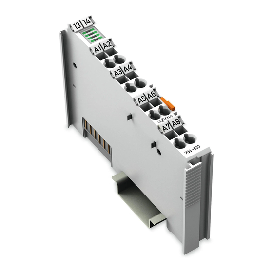
8do 24v dc 0.5a, diagnostics 8-channel digital output; 24 vdc; short-circuit protected; high-side switching; with diagnostics
Hide thumbs Also See for I/O System 750:
Table of Contents

Advertisement

Quick Links

Manual
WAGO I/O System 750
750-537
8DO 24V DC 0.5A, diagnostics
8-Channel Digital Output; 24 VDC; short-circuit
protected; high-side switching; with diagnostics
Version 1.2.0

Advertisement

Table of Contents
loading

Summary of Contents for WAGO I/O System 750

  • Page 1 Manual WAGO I/O System 750 750-537 8DO 24V DC 0.5A, diagnostics 8-Channel Digital Output; 24 VDC; short-circuit protected; high-side switching; with diagnostics Version 1.2.0...
  • Page 2 We wish to point out that the software and hardware terms as well as the trademarks of companies used and/or mentioned in the present manual are generally protected by trademark or patent. WAGO is a registered trademark of WAGO Verwaltungsgesellschaft mbH. Manual Version 1.2.0...
  • Page 3: Table Of Contents

    WAGO I/O System 750 Table of Contents 750-537 8DO 24V DC 0.5A, diagnostics Table of Contents Notes about this Documentation ............. 5 Validity of this Documentation..............5 Copyright ....................5 Symbols ....................6 Number Notation ..................8 Font Conventions ................... 8 Important Notes ..................
  • Page 4 Table of Contents WAGO I/O System 750 750-537 8DO 24V DC 0.5A, diagnostics Use in Hazardous Environments ............37 Marking Configuration Examples ............38 7.1.1 Marking for Europe According to ATEX and IECEx ......38 7.1.2 Marking for the United States of America (NEC) and Canada (CEC) ....................
  • Page 5: Notes About This Documentation

    Consider power layout of the WAGO I/O System 750! In addition to these operating instructions, you will also need the manual for the used fieldbus coupler or controller, which can be downloaded at www.wago.com. There, you can obtain important information including information on electrical isolation, system power and supply specifications.
  • Page 6: Symbols

    Notes about this Documentation WAGO I/O System 750 750-537 8DO 24V DC 0.5A, diagnostics Symbols Personal Injury! Indicates a high-risk, imminently hazardous situation which, if not avoided, will result in death or serious injury. Personal Injury Caused by Electric Current! Indicates a high-risk, imminently hazardous situation which, if not avoided, will result in death or serious injury.
  • Page 7 WAGO I/O System 750 Notes about this Documentation 750-537 8DO 24V DC 0.5A, diagnostics Additional Information: Refers to additional information which is not an integral part of this documentation (e.g., the Internet). Manual Version 1.2.0...
  • Page 8: Number Notation

    Notes about this Documentation WAGO I/O System 750 750-537 8DO 24V DC 0.5A, diagnostics Number Notation Table 1: Number Notation Number Code Example Note Decimal Normal notation Hexadecimal 0x64 C notation Binary '100' In quotation marks, nibble separated '0110.0100' with dots (.)
  • Page 9: Important Notes

    2.1.1 Subject to Changes WAGO Kontakttechnik GmbH & Co. KG reserves the right to provide for any alterations or modifications. WAGO Kontakttechnik GmbH & Co. KG owns all rights arising from the granting of patents or from the legal protection of utility patents.
  • Page 10: Technical Condition Of Specified Devices

    The implementation of safety functions such as EMERGENCY STOP or safety door monitoring must only be performed by the F I/O modules within the modular WAGO I/O System 750. Only these safe F I/O modules ensure functional safety in accordance with the latest international standards. WAGO's interference-free output modules can be controlled by the safety function.
  • Page 11: 2.1.4.1.2 Packaging

    WAGO I/O System 750 Important Notes 750-537 8DO 24V DC 0.5A, diagnostics Environmentally friendly disposal benefits health and protects the environment from harmful substances in electrical and electronic equipment. • Observe national and local regulations for the disposal of electrical and electronic equipment.
  • Page 12: Safety Advice (Precautions)

    Important Notes WAGO I/O System 750 750-537 8DO 24V DC 0.5A, diagnostics Safety Advice (Precautions) For installing and operating purposes of the relevant device to your system the following safety precautions shall be observed: Do not work on devices while energized! All power sources to the device shall be switched off prior to performing any installation, repair or maintenance work.
  • Page 13 WAGO I/O System 750 Important Notes 750-537 8DO 24V DC 0.5A, diagnostics Power from SELV/PELV power supply only! All field signals and field supplies connected to this I/O module (750-537) must be powered from SELV/PELV power supply(s)! Inadequate wire cross sections can cause temperature increases! To avoid increasing thermal risks, only use conductor cross-sections sufficient for the required maximum load current.
  • Page 14 Important Notes WAGO I/O System 750 750-537 8DO 24V DC 0.5A, diagnostics Do not exceed the maximum total current for I/O modules (5 VDC) via data contacts! The maximum permissible total current for internal system supply of the I/O modules may not be exceeded. The permissible total current is specified in the technical data of the head station and power supply.
  • Page 15 WAGO I/O System 750 Important Notes 750-537 8DO 24V DC 0.5A, diagnostics Do not reverse the polarity of connection lines! Avoid reverse polarity of data and power supply lines, as this may damage the devices involved. Avoid electrostatic discharge! The devices are equipped with electronic components that may be destroyed by electrostatic discharge when touched.
  • Page 16: Device Description

    Device Description WAGO I/O System 750 750-537 8DO 24V DC 0.5A, diagnostics Device Description The 750-537 (8DO 24V DC 0.5A, diagnostics) Digital Output Module transmits binary control signals from the automation device to the connected actuators (e.g., solenoid valves, contactors, transmitters or other electrical loads).
  • Page 17 WAGO I/O System 750 Device Description 750-537 8DO 24V DC 0.5A, diagnostics The I/O module 750-537 (8DO 24V DC 0.5A, diagnostics) receives the 24 V voltage supply for the field level from an upstream I/O module or from the fieldbus coupler/controller via blade-formed power jumper contacts. It then provides these potentials to subsequent I/O modules via spring-formed power jumper contacts.
  • Page 18: View

    Device Description WAGO I/O System 750 750-537 8DO 24V DC 0.5A, diagnostics View Figure 1: View Table 3: Legend for Figure “View” Pos. Description Details See Section Marking possibility with Mini- Status LEDs “Device Description” > “Display Elements” Data contacts “Device Description”...
  • Page 19: Connectors

    WAGO I/O System 750 Device Description 750-537 8DO 24V DC 0.5A, diagnostics Connectors 3.2.1 Data Contacts/Local Bus Communication between the fieldbus coupler/controller and the I/O modules as well as the system supply of the I/O modules is carried out via the local bus. The contacting for the local bus consists of 6 data contacts, which are available as self-cleaning gold spring contacts.
  • Page 20: Power Jumper Contacts/Field Supply

    Device Description WAGO I/O System 750 750-537 8DO 24V DC 0.5A, diagnostics 3.2.2 Power Jumper Contacts/Field Supply Risk of injury due to sharp-edged blade contacts! The blade contacts are sharp-edged. Handle the I/O module carefully to prevent injury. Do not touch the blade contacts.
  • Page 21 WAGO I/O System 750 Device Description 750-537 8DO 24V DC 0.5A, diagnostics Use supply modules for ground (earth)! The I/O module has no power jumper contacts for receiving and transmitting the earth potential. Use a supply module when an earth potential is needed for the subsequent I/O modules.
  • Page 22: Cage Clamp ® Connectors

    Device Description WAGO I/O System 750 750-537 8DO 24V DC 0.5A, diagnostics 3.2.3 CAGE CLAMP ® Connectors Figure 4: CAGE CLAMP ® Connectors Table 5: Legend for Figure “CAGE CLAMP ® Connectors” Channel Designation Connector Function DO 1 Output DO 1: Signal voltage...
  • Page 23: Display Elements

    WAGO I/O System 750 Device Description 750-537 8DO 24V DC 0.5A, diagnostics Display Elements Figure 5: Display Elements Table 6: Legend for Figure “Display Elements“ Channel Designation Status DO 1 Error DO 1 Status DO 2 Error DO 2 Status DO 3...
  • Page 24: Schematic Diagram

    Device Description WAGO I/O System 750 750-537 8DO 24V DC 0.5A, diagnostics Schematic Diagram Figure 6: Schematic Diagram Manual Version 1.2.0...
  • Page 25: Technical Data

    WAGO I/O System 750 Device Description 750-537 8DO 24V DC 0.5A, diagnostics Technical Data 3.5.1 Device Data Table 8: Technical Data – Device Width 12 mm Depth (from upper edge of DIN 35 rail) 60.6 mm Height 100 mm Weight Approx.
  • Page 26: Connection Type

    Device Description WAGO I/O System 750 750-537 8DO 24V DC 0.5A, diagnostics 3.5.5 Connection Type Table 12: Technical Data – Field Wiring Connection technology CAGE CLAMP ® Conductor cross-section 0.08 mm² … 2.5 mm², AWG 28 … 14 Strip length 8 mm …...
  • Page 27: Approvals

    Approvals More information about approvals. Detailed references to the approvals are listed in the document “Overview on WAGO I/O System 750 approvals”, which you can find via the internet under: www.wago.com  DOWNLOADS  Documentation  System Description. The following approvals have been granted to 750-537 I/O modules:...
  • Page 28 Device Description WAGO I/O System 750 750-537 8DO 24V DC 0.5A, diagnostics The following ship approvals have been granted to 750-537 I/O modules: ABS (American Bureau of Shipping) Federal Maritime and Hydrographic Agency BV (Bureau Veritas) DNV (Det Norske Veritas)
  • Page 29: Standards And Guidelines

    WAGO I/O System 750 Device Description 750-537 8DO 24V DC 0.5A, diagnostics Standards and Guidelines 750-537 I/O modules meet the following requirements on emission and immunity of interference: EMC CE-Emission of interference EN 61000-6-3 EMC CE-Immunity to interference EN 61000-6-2...
  • Page 30: Process Image

    Process Image WAGO I/O System 750 750-537 8DO 24V DC 0.5A, diagnostics Process Image Mapping of process data in the process image of fieldbus systems The representation of the process data of some I/O modules or their variants in the process image depends on the fieldbus coupler/controller used. Please take this information from the section “I/O Modules”...
  • Page 31: Mounting

    WAGO I/O System 750 Mounting 750-537 8DO 24V DC 0.5A, diagnostics Mounting Do not work when devices are energized! High voltage can cause electric shock or burns. Switch off all power to the device prior to performing any installation, repair or maintenance work.
  • Page 32: Mounting Sequence

    Always plug a bus end module (e.g. 750-600) onto the end of the fieldbus node! You must always use a bus end module at all fieldbus nodes with WAGO I/O System 750 fieldbus couplers or controllers to guarantee proper data transfer.
  • Page 33: Figure 7: Inserting I/O Module (Example)

    WAGO I/O System 750 Mounting 750-537 8DO 24V DC 0.5A, diagnostics Figure 7: Inserting I/O Module (Example) Press the I/O module into the assembly until the I/O module snaps into the carrier rail. Figure 8: Snap the I/O Module into Place (Example) Check that the I/O module is seated securely on the carrier rail and in the assembly.
  • Page 34: Removing The I/O Module

    Mounting WAGO I/O System 750 750-537 8DO 24V DC 0.5A, diagnostics 5.2.2 Removing the I/O Module Remove the I/O module from the assembly by pulling the release tab. Figure 9: Removing the I/O Module (Example) Electrical connections for data or power jumper contacts are disconnected when removing the I/O module.
  • Page 35: Connect Devices

    Do not connect more than one conductor at one single connection! If more than one conductor must be routed to one connection, these must be connected in an up-circuit wiring assembly, for example using WAGO feed- through terminals. For opening the CAGE CLAMP ®...
  • Page 36: Connection Examples

    Connect Devices WAGO I/O System 750 750-537 8DO 24V DC 0.5A, diagnostics Connection Examples Figure 11: Connection Example 1-Conductor Connection Manual Version 1.2.0...
  • Page 37: Use In Hazardous Environments

    Use in Hazardous Environments 750-537 8DO 24V DC 0.5A, diagnostics Use in Hazardous Environments The WAGO I/O System 750 (electrical equipment) is designed for use in Zone 2 hazardous areas and shall be used in accordance with the marking and installation regulations.
  • Page 38: Marking Configuration Examples

    Use in Hazardous Environments WAGO I/O System 750 750-537 8DO 24V DC 0.5A, diagnostics Marking Configuration Examples 7.1.1 Marking for Europe According to ATEX and IECEx Figure 12: Marking Example According to ATEX and IECEx Figure 13: Text Detail – Marking Example According to ATEX and IECEx Manual Version 1.2.0...
  • Page 39: Table 18: Description Of Marking Example According To Atex And Iecex

    WAGO I/O System 750 Use in Hazardous Environments 750-537 8DO 24V DC 0.5A, diagnostics Table 18: Description of Marking Example According to ATEX and IECEx Marking Description TUEV 07 ATEX 554086 X Approving authority resp. certificate numbers IECEx TUN 09.0001 X...
  • Page 40: Figure 14: Marking Example For Approved I/O Module Ex I According To

    Use in Hazardous Environments WAGO I/O System 750 750-537 8DO 24V DC 0.5A, diagnostics Figure 14: Marking Example for Approved I/O Module Ex i According to ATEX and IECEx Figure 15: Text Detail – Marking Example for Approved I/O ModuleEx i According to ATEX and...
  • Page 41: Table 19: Description Of Marking Example For Approved I/O Module Ex I According To Atex And Iecex

    WAGO I/O System 750 Use in Hazardous Environments 750-537 8DO 24V DC 0.5A, diagnostics Table 19: Description of Marking Example for Approved I/O Module Ex I According to ATEX and IECEx Marking Description TUEV 12 ATEX 106032 X Approving authority resp. certificate numbers...
  • Page 42: Marking For The United States Of America (Nec) And Canada (Cec)

    Use in Hazardous Environments WAGO I/O System 750 750-537 8DO 24V DC 0.5A, diagnostics 7.1.2 Marking for the United States of America (NEC) and Canada (CEC) Figure 16: Marking Example According to NEC Figure 17: Text Detail – Marking Example According to NEC 500...
  • Page 43: Figure 18: Text Detail - Marking Example For Approved I/O Module Ex I

    WAGO I/O System 750 Use in Hazardous Environments 750-537 8DO 24V DC 0.5A, diagnostics Figure 18: Text Detail – Marking Example for Approved I/O Module Ex i According to NEC 505 Table 21: Description of Marking Example for Approved I/O Module Ex i According to NEC 505...
  • Page 44: Figure 20: Text Detail - Marking Example For Approved I/O Module Ex I

    Use in Hazardous Environments WAGO I/O System 750 750-537 8DO 24V DC 0.5A, diagnostics Figure 20: Text Detail – Marking Example for Approved I/O Module Ex i According to CEC 18 attachment J Table 23: Description of Marking Example for Approved I/O Module Ex i According to CEC 18...
  • Page 45: Installation Regulations

    Special Notes including Explosion Protection The following warning notices are to be posted in the immediately proximity of the WAGO I/O System 750 (hereinafter “product”): WARNING – DO NOT REMOVE OR REPLACE FUSED WHILE ENERGIZED! WARNING – DO NOT DISCONNECT WHILE ENERGIZED! WARNING –...
  • Page 46 Use in Hazardous Environments WAGO I/O System 750 750-537 8DO 24V DC 0.5A, diagnostics Explosive atmosphere occurring simultaneously with assembly, installation or repair work must be ruled out. Among other things, these include the following activities • Insertion and removal of components •...
  • Page 47: Special Notes Regarding Ansi/Isa Ex

    WAGO I/O System 750 Use in Hazardous Environments 750-537 8DO 24V DC 0.5A, diagnostics 7.2.2 Special Notes Regarding ANSI/ISA Ex For ANSI/ISA Ex acc. to UL File E198726, the following additional requirements apply: • Use in Class I, Division 2, Group A, B, C, D or non-hazardous areas only •...
  • Page 48: List Of Figures

    List of Figures WAGO I/O System 750 750-537 8DO 24V DC 0.5A, diagnostics List of Figures Figure 1: View ....................18 Figure 2: Data Contacts ..................19 Figure 3: Power Jumper Contacts ..............20 Figure 4: CAGE CLAMP ® Connectors ..............22 Figure 5: Display Elements.................23 Figure 6: Schematic Diagram ................24...
  • Page 49: List Of Tables

    WAGO I/O System 750 List of Tables 750-537 8DO 24V DC 0.5A, diagnostics List of Tables Table 1: Number Notation ................... 8 Table 2: Font Conventions .................. 8 Table 3: Legend for Figure “View” ..............18 Table 4: Legend for Figure “Power Jumper Contacts” ........20 Table 5: Legend for Figure “CAGE CLAMP...
  • Page 50 WAGO Kontakttechnik GmbH & Co. KG Postfach 2880 • D - 32385 Minden Hansastraße 27 • D - 32423 Minden Phone: +49 571 887 – 0 Fax: +49 571 887 – 844169 E-Mail: info@wago.com Internet: www.wago.com...

This manual is also suitable for:

750-537

Table of Contents