WAGO I/O System 750 Manual
Hide thumbs
Also See for I/O System 750:
- Manual (468 pages) ,
- Quickstart reference (54 pages) ,
- Product manual (28 pages)

Related Manuals for WAGO I/O System 750


Summary of Contents for WAGO I/O System 750
- Page 1 Manual WAGO I/O System 750 750-8210/040-000 PFC200; G2; 4ETH; XTR Controller PFC200; 2nd Generation; 4 x ETHERNET; Extreme Version 1.7.0, valid from FW Version 04.01.10(23)
- Page 2 We wish to point out that the software and hardware terms as well as the trademarks of companies used and/or mentioned in the present manual are generally protected by trademark or patent. WAGO is a registered trademark of WAGO Verwaltungsgesellschaft mbH. Manual Version 1.7.0, valid from FW Version 04.01.10(23)
-
Page 3: Table Of Contents
WAGO I/O System 750 Table of Contents 750-8210/040-000 PFC200; G2; 4ETH; XTR Table of Contents Notes about this Documentation ............. 9 Validity of this Documentation..............9 Copyright ....................9 Property rights ..................10 Symbols ....................12 Number Notation .................. 14 Font Conventions ................. - Page 4 Table of Contents WAGO I/O System 750 750-8210/040-000 PFC200; G2; 4ETH; XTR 4.3.6 Local Bus ..................44 4.3.7 ETHERNET ..................45 4.3.8 Connection Type ................45 4.3.9 Mechanical Environmental Conditions ..........46 4.3.10 Climatic Environmental Conditions ........... 46 Approvals ..................... 47 Standards and Guidelines ..............
- Page 5 Assigning an IP Address using DHCP ..........107 Changing an IP Address Using the “CBM” Configuration Tool and a 8.3.2 Terminal Program ................108 Changing an IP Address using “WAGO Ethernet Settings” .... 111 8.3.3 8.3.4 Temporarily Setting Fixed IP Addresses ........113 Testing the Network Connection ............
- Page 6 Table of Contents WAGO I/O System 750 750-8210/040-000 PFC200; G2; 4ETH; XTR General Notes ..................136 CODESYS V3 Priorities ..............137 Memory Spaces under CODESYS V3 ..........138 9.3.1 Program and Data Memory ............138 9.3.2 Function Block Limitation ............... 138 9.3.3...
- Page 7 750-8210/040-000 PFC200; G2; 4ETH; XTR “Vendor Information” Page ............ 168 15.2.1.1.2 “PLC Runtime Information” Page .......... 169 15.2.1.1.3 “WAGO Software License Agreement” Page ......170 15.2.1.1.4 “Open Source Licenses” Page ..........171 15.2.1.1.5 “WBM Third Party License Information” Page ....... 172 15.2.1.1.6...
- Page 8 Table of Contents WAGO I/O System 750 750-8210/040-000 PFC200; G2; 4ETH; XTR “Diagnostic” Tab ................ 240 15.2.1.5 “Diagnostic Information” Page ..........240 15.2.1.5.1 15.3 Process Data Architecture ..............241 15.3.1 Digital Input Modules..............242 15.3.1.1 2-Channel Digital Input Modules ..........242 15.3.1.2...
-
Page 9: Notes About This Documentation
Manual by third parties that violate pertinent copyright provisions is prohibited. Reproduction, translation, electronic and phototechnical filing/archiving (e.g., photocopying) as well as any amendments require the written consent of WAGO GmbH & Co. KG, Minden, Germany. Non-observance will involve the right to assert damage claims. Manual... -
Page 10: Property Rights
Notes about this Documentation WAGO I/O System 750 750-8210/040-000 PFC200; G2; 4ETH; XTR Property rights Third-party trademarks are used in this documentation. This section contains the trademarks used. The “®” and “TM” symbols are omitted hereinafter. • ® ® Adobe and Acrobat are registered trademarks of Adobe Systems Inc. - Page 11 WAGO I/O System 750 Notes about this Documentation 750-8210/040-000 PFC200; G2; 4ETH; XTR • ® PROFIBUS is a registered trademark of the PROFIBUS Nutzerorganisation e.V. (PNO). • ® PROFINET is a registered trademark of the PROFIBUS Nutzerorganisation e.V. (PNO). •...
-
Page 12: Symbols
Notes about this Documentation WAGO I/O System 750 750-8210/040-000 PFC200; G2; 4ETH; XTR Symbols Personal Injury! Indicates a high-risk, imminently hazardous situation which, if not avoided, will result in death or serious injury. Personal Injury Caused by Electric Current! Indicates a high-risk, imminently hazardous situation which, if not avoided, will result in death or serious injury. - Page 13 WAGO I/O System 750 Notes about this Documentation 750-8210/040-000 PFC200; G2; 4ETH; XTR Additional Information: Refers to additional information which is not an integral part of this documentation (e.g., the Internet). Manual Version 1.7.0, valid from FW Version 04.01.10(23)
-
Page 14: Number Notation
Notes about this Documentation WAGO I/O System 750 750-8210/040-000 PFC200; G2; 4ETH; XTR Number Notation Table 1: Number Notation Number Code Example Note Decimal Normal notation Hexadecimal 0x64 C notation Binary '100' In quotation marks, nibble separated '0110.0100' with dots (.) -
Page 15: Important Notes
2.1.1 Subject to Changes WAGO GmbH & Co. KG reserves the right to provide for any alterations or modifications. WAGO GmbH & Co. KG owns all rights arising from the granting of patents or from the legal protection of utility patents. Third-party products are always mentioned without any reference to patent rights. -
Page 16: Technical Condition Of Specified Devices
These modules contain no parts that can be serviced or repaired by the user. The following actions will result in the exclusion of liability on the part of WAGO GmbH & Co. KG: •... -
Page 17: Safety Advice (Precautions)
WAGO I/O System 750 Important Notes 750-8210/040-000 PFC200; G2; 4ETH; XTR Safety Advice (Precautions) For installing and operating purposes of the relevant device to your system the following safety precautions shall be observed: Do not work on devices while energized! All power sources to the device shall be switched off prior to performing any installation, repair or maintenance work. - Page 18 Important Notes WAGO I/O System 750 750-8210/040-000 PFC200; G2; 4ETH; XTR Power from SELV/PELV power supply only! All field signals and field supplies connected to this XTR fieldbus controller (750- 8210/040-000) must be powered from SELV/PELV power supply(s)! Inadequate wire cross sections can cause temperature increases! To avoid increasing thermal risks, only use conductor cross-sections sufficient for the required maximum load current.
- Page 19 WAGO I/O System 750 Important Notes 750-8210/040-000 PFC200; G2; 4ETH; XTR Clean only with permitted materials! Clean housing and soiled contacts with propanol. Do not use any contact spray! Do not use any contact spray. The spray may impair contact area functionality in connection with contamination.
-
Page 20: Licensing Terms Of The Software Package Used
They can be accessed via the WBM page “Legal Information” > “Open Source Software.” You can obtain the source code with licensing terms of the open-source software from WAGO GmbH & Co. KG on request. Send your request to with the subject “Controller Board Support Package.” support@wago.com Manual Version 1.7.0, valid from FW Version 04.01.10(23) -
Page 21: Special Use Conditions For Ethernet Devices
Please note the following when using ETHERNET devices in your system: • Do not connect control components and control networks directly to an open network such as the Internet or an office network. WAGO recommends putting control components and control networks behind a firewall. •... -
Page 22: Overview
DIN rail and stands out on account of its various interfaces. This controller is specifically designed for rail and marine applications. You can connect all available I/O modules of the WAGO I/O System 750 XTR to the controller, enabling it to internally process analog and digital signals from the automation environment, or to supply these signals to other devices via one of the available interfaces. - Page 23 WAGO I/O System 750 Overview 750-8210/040-000 PFC200; G2; 4ETH; XTR The physical interfaces (ports) are assigned via logical bridges and can be e.g., configured via the WBM. All interfaces support: • 10BASE-T/100BASE-TX • Full/Half duplex • Autonegotiation • Auto-MDI(X) (automatic uplink and crossover switching) In the controller, all input signals from the sensors are combined.
- Page 24 Overview WAGO I/O System 750 750-8210/040-000 PFC200; G2; 4ETH; XTR • a DNS server • a CODESYS V3 Runtime Environment Based on IEC-61131-3 programming, data processing takes place on site in the controller. The logical process results can be output directly to the actuators or transmitted via a connected fieldbus to the higher level controller.
-
Page 25: Properties
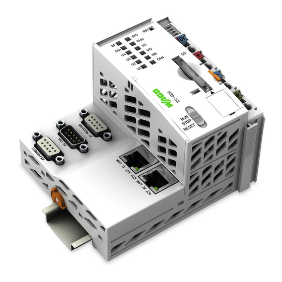
WAGO I/O System 750 Properties 750-8210/040-000 PFC200; G2; 4ETH; XTR Properties Hardware Description 4.1.1 View Figure 1: View Table 3: Legend for Figure “View” Item Description See section Marking options (Mini WSB) “Display Elements” > “Power LED indicators – power pupply Supply Indicating Elements”... - Page 26 Properties WAGO I/O System 750 750-8210/040-000 PFC200; G2; 4ETH; XTR “Connectors” > “Service Service Interface (behind the flap) Interface” “Operating elements” > Mode selector switch “Operating Mode Switch” “Connecting” > “Connecting Network cable tie slot Network Cables” “Connectors” > “Network ETHERNET connectors –...
-
Page 27: Labeling
WAGO I/O System 750 Properties 750-8210/040-000 PFC200; G2; 4ETH; XTR 4.1.2 Labeling The front labeling includes: Device designation Name of the display elements, connections and control elements Serial number with hardware and firmware version The side labeling includes: Manufacturer's identification... -
Page 28: Connectors
Properties WAGO I/O System 750 750-8210/040-000 PFC200; G2; 4ETH; XTR 4.1.3 Connectors 4.1.3.1 Wiring Level ® Figure 3: CAGE CLAMP Connectors Table 4: Legend for Figure “CAGE CLAMP ® Connectors” Contact Designation Description 24 V System power supply voltage +24 V Field-side power supply voltage U −... -
Page 29: Service Interface
750-8210/040-000 PFC200; G2; 4ETH; XTR 4.1.3.2 Service Interface The service interface is located behind the flap. The Service interface is used for communication with WAGO-I/O-CHECK and “WAGO Ethernet Settings”. Figure 4: Service Interface (Closed and Open Flap) Table 5: Service Interface... -
Page 30: Network Connectors
Properties WAGO I/O System 750 750-8210/040-000 PFC200; G2; 4ETH; XTR 4.1.3.3 Network Connectors Figure 5: Network Connections – X1, X2, X11, X12 Table 6: Legend for Figure “Network Connections – X1, X2, X11, X12” Contact Signal Description TD + Transmit Data + TD −... -
Page 31: System Contacts
WAGO I/O System 750 Properties 750-8210/040-000 PFC200; G2; 4ETH; XTR 4.1.4 System Contacts 4.1.4.1 Data Contacts Communication between the controller and the I/O modules and system power supply for the I/O modules is provided via the local bus, which consists of 6 data contacts designed as self-cleaning gold spring contacts. -
Page 32: Power Jumper Contacts
Properties WAGO I/O System 750 750-8210/040-000 PFC200; G2; 4ETH; XTR 4.1.4.2 Power Jumper Contacts The controller 750-8210/040-000 is equipped with 2 self-cleaning power contacts for transferring of the field-side power supply to down-circuit I/O modules. These contacts are designed as spring contacts. -
Page 33: Display Elements
WAGO I/O System 750 Properties 750-8210/040-000 PFC200; G2; 4ETH; XTR 4.1.5 Display Elements 4.1.5.1 Power Supply LEDs Figure 8: Power Supply Indicating Elements Table 8: Legend for Figure “Power Supply Indicating Elements” Description Color Description Green/off Status of system power supply voltage... -
Page 34: System/Fieldbus Leds
Module status Orange/Off Red/Green/ Without function Orange/Off User LED 7, programmable using function Red/Green/ blocks from the WAGO libraries to control the Orange/Off LEDs User LED 6, programmable using function Red/Green/ blocks from the WAGO libraries to control the Orange/Off... -
Page 35: Network Connector Leds
WAGO I/O System 750 Properties 750-8210/040-000 PFC200; G2; 4ETH; XTR 4.1.5.3 Network Connector LEDs Figure 10: Indicating Elements, RJ-45 Jacks Table 10: Legend for Figure “Indicating Elements, RJ-45 Jacks” Designation Color Description Green/Off ETHERNET connection status Yellow/Off ETHERNET data exchange Manual Version 1.7.0, valid from FW Version 04.01.10(23) -
Page 36: Memory Card Slot Led
Properties WAGO I/O System 750 750-8210/040-000 PFC200; G2; 4ETH; XTR 4.1.5.4 Memory Card Slot LED Figure 11: Indicating Elements, Memory Card Slot Table 11: Legend for Figure “Indicating Elements, Memory Card Slot” Designation Color Description Yellow/Off Memory card status Manual... -
Page 37: Operating Elements
WAGO I/O System 750 Properties 750-8210/040-000 PFC200; G2; 4ETH; XTR 4.1.6 Operating Elements 4.1.6.1 Operating Mode Switch Figure 12: Mode Selector Switch </dg_ Table 12: Mode Selector Switch Position Actuation Function Normal operation Latching CODESYS V3 applications running. Stop STOP Latching All CODESYS V3 applications have stopped. -
Page 38: Reset Button
Properties WAGO I/O System 750 750-8210/040-000 PFC200; G2; 4ETH; XTR 4.1.6.2 Reset Button Figure 13: Reset Button The Reset button is installed behind drilling to prevent operating errors. It is a shortstroke button with a low actuating force of 1.1 N … 2.1 N (110 gf … 210 gf). -
Page 39: Memory Card Slot
</dg_ Only use recommended memory cards! Use only the SD memory cards available from WAGO (item No. 758-879/000- 001 and 758-879/000-2108) as these are suitable for industrial applications subjected to environmental extremes and for use in this device. Compatibility with other commercially available storage media cannot be guaranteed. -
Page 40: Schematic Diagram
Properties WAGO I/O System 750 750-8210/040-000 PFC200; G2; 4ETH; XTR Schematic Diagram Figure 15: Schematic diagram Manual Version 1.7.0, valid from FW Version 04.01.10(23) -
Page 41: Technical Data
Push-push mechanism, sealable cover lid Type of memory card SD and SDHC up to 32 Gbytes (All guaranteed properties are valid only in connection with the WAGO memory cards 758-879/000-001 and 758-879/000-2108.) Manual Version 1.7.0, valid from FW Version 04.01.10(23) -
Page 42: Power Supply
Properties WAGO I/O System 750 750-8210/040-000 PFC200; G2; 4ETH; XTR 4.3.3 Power Supply Table 15: Technical Data – Power Supply System supply voltage 24 VDC (SELV/PELV) • Power supply via pluggable connector ® (CAGE CLAMP connection) • Derating must be observed! - Page 43 WAGO I/O System 750 Properties 750-8210/040-000 PFC200; G2; 4ETH; XTR Buffer for system power supply! The system power supply and, if necessary, the field supply must be buffered to bridge power outages. As the power demand depends on the respective node configuration, buffering is not implemented internally.
-
Page 44: Clock
Properties WAGO I/O System 750 750-8210/040-000 PFC200; G2; 4ETH; XTR 4.3.4 Clock </dg_ Table 16: Technical Data – Clock Drift - system clock (25 °C) 20 ppm Drift - RTC (25 °C) 3 ppm Buffer time RTC (25 °C) 30 days... -
Page 45: Ethernet
WAGO I/O System 750 Properties 750-8210/040-000 PFC200; G2; 4ETH; XTR 4.3.7 ETHERNET Table 19: Technical Data – ETHERNET ETHERNET 4 x RJ-45, configurable combinations via bridges Twisted Pair S-UTP, 100 Ω, Cat 5, Transmission medium 100 m maximum cable length Baud rate 10/100 Mbit/s;... -
Page 46: Mechanical Environmental Conditions
Properties WAGO I/O System 750 750-8210/040-000 PFC200; G2; 4ETH; XTR 4.3.9 Mechanical Environmental Conditions Table 23: Technical Data – Mechanical Environmental Conditions Vibration resistance Max. 5g Follow the installation instructions 4.3.10 Climatic Environmental Conditions Table 24: Technical Data – Climatic Environmental Conditions −40 …... -
Page 47: Approvals
WAGO I/O System 750 Properties 750-8210/040-000 PFC200; G2; 4ETH; XTR Approvals For current approvals, please go to: www.wago.com/<Item number>. The following approvals have been granted to the “PFC200; G2; 4ETH; XTR” controller (750-8210/040-000): Conformity Marking Ordinary UL61010-2-201 Locations The following ship approvals have been granted to the “PFC200; G2; 4ETH;... -
Page 48: Standards And Guidelines
Properties WAGO I/O System 750 750-8210/040-000 PFC200; G2; 4ETH; XTR Standards and Guidelines The “PFC200; G2; 4ETH; XTR” controller (750-8210/040-000) fulfills the following standards and regulations: Table 25: Climatic and Mechanical Environmental Conditions and Shipbuilding Standard Test Value Transport EN 60870-2-2... -
Page 49: Table 26: Emc - Immunity To Interference
WAGO I/O System 750 Properties 750-8210/040-000 PFC200; G2; 4ETH; XTR The controller 750-8210/040-000 meets the following EMC standards as these standards relate to the controller: Table 26: EMC – Immunity to Interference Standard Test Value Electrostatic Discharge • EN 61000-4-2 8 kV (contact discharge) •... - Page 50 Properties WAGO I/O System 750 750-8210/040-000 PFC200; G2; 4ETH; XTR Table 26: EMC – Immunity to Interference Standard Test Value Line Frequency Disturbances • EN 60255-26 Standard not applicable Alternating Components of the Voltage to DC Line Connections • EN 61000-4-17 15 % •...
-
Page 51: Table 27: Emc - Emission Of Interference
WAGO I/O System 750 Properties 750-8210/040-000 PFC200; G2; 4ETH; XTR Table 27: EMC – Emission of Interference Standard Test Value Enclosure Emission of Interference • EN 61000-6-3 30 dB(µV/m), QP, 30 MHz … 230 MHz • EN 55032 Class B 37 dB(µV/m), QP, 230 MHz …... - Page 52 Properties WAGO I/O System 750 750-8210/040-000 PFC200; G2; 4ETH; XTR Table 27: EMC – Emission of Interference Standard Test Value Conducted Emission of Interference – Line Connection DC Voltage • EN 61000-6-3 79 dB(µV) QP, 0.15 MHz … 0.5 MHz •...
-
Page 53: Table 28: Standards And Rated Conditions For Rail Applications (En 50155:2017)
According to annex G MTBF values (acc. to MIL-HDBK-217-F2) are available and can be provided on request for specific projects WAGO is a company certified in accordance with the IRIS quality standard. Manual Version 1.7.0, valid from FW Version 04.01.10(23) -
Page 54: Functions
Functions WAGO I/O System 750 750-8210/040-000 PFC200; G2; 4ETH; XTR Functions </dg_ Network 5.1.1 Interface Configuration The X1, X2, X11 and X12 network interfaces of the controller are connected with an integrated configurable 5-port switch, in which the fifth port is connected to the CPU. -
Page 55: Mac Id And Ip Address Assignment Examples
WAGO I/O System 750 Functions 750-8210/040-000 PFC200; G2; 4ETH; XTR 5.1.1.1 MAC ID and IP Address Assignment Examples One common network where all four ports share a common IP address Figure 17: One Bridge with Four Ports Table 29: MAC ID and IP Address Assignment for One Bridge with Four Ports... -
Page 56: Figure 19: Two Bridges With One/Three Ports
Functions WAGO I/O System 750 750-8210/040-000 PFC200; G2; 4ETH; XTR Two separate networks where one port has its own IP address and three ports share a common IP address Figure 19: Two Bridges with One/Three Ports Table 31: MAC ID and IP Address Assignment for Two Bridges with One/Three Ports... -
Page 57: Figure 21: Four Bridges With One/One/One/One Ports
WAGO I/O System 750 Functions 750-8210/040-000 PFC200; G2; 4ETH; XTR Four separate networks where each port has its own IP address Figure 21: Four Bridges with One/One/One/One Ports Table 33: MAC ID and IP Address Assignment for Four Bridges with One/One/One/One Ports... -
Page 58: Network Security
Functions WAGO I/O System 750 750-8210/040-000 PFC200; G2; 4ETH; XTR 5.1.2 Network Security 5.1.2.1 Users and Passwords Several groups of users are provided in the controller which can be used for various services. Default passwords are set for all users. We strongly recommend changing these... -
Page 59: Wbm User Group
WAGO I/O System 750 Functions 750-8210/040-000 PFC200; G2; 4ETH; XTR 5.1.2.1.2 WBM User Group The WBM uses part of the Linux users. Table 35: WBM Users Users Permissions Default Password root All (administrator) wago admin All (administrator) wago user Supported to a limited extent... -
Page 60: Linux User Group
Functions WAGO I/O System 750 750-8210/040-000 PFC200; G2; 4ETH; XTR 5.1.2.1.3 Linux User Group The Linux user group includes the actual users of the operating system, which is likewise used by most services. Table 36: Linux Users User Special Feature... -
Page 61: Web Protocols For Wbm Access
WAGO I/O System 750 Functions 750-8210/040-000 PFC200; G2; 4ETH; XTR 5.1.2.2 Web Protocols for WBM Access The HTTP and HTTPS web protocols can be used to access the WBM pages for the controller. HTTPS is preferred because it uses the SSL/TLS protocol. The... - Page 62 Functions WAGO I/O System 750 750-8210/040-000 PFC200; G2; 4ETH; XTR BSI Guidelines on Migration to TLS 1.2 The German Federal Office for Information Security guidelines on migration to TLS 1.2 contain “compatibility matrices” that show what software is comparable with TLS 1.2.
-
Page 63: Root Certificates
WAGO I/O System 750 Functions 750-8210/040-000 PFC200; G2; 4ETH; XTR 5.1.2.3 Root Certificates For communication encrypted with TLS, root certificates are used to verify the authenticity of the communication partner. A root certificate, which is signed by a certificate authority, serves to verify the validity of all certificates issued by this certificate authority. -
Page 64: Network Configuration
Functions WAGO I/O System 750 750-8210/040-000 PFC200; G2; 4ETH; XTR </dg_ 5.1.3 Network Configuration 5.1.3.1 Host Name/Domain Name Without a host name configuration, the controller is assigned a default name which includes the last three values of the controller's MAC address, e.g., “PFCx00-A1A2A3.”... - Page 65 WAGO I/O System 750 Functions 750-8210/040-000 PFC200; G2; 4ETH; XTR On the basis of the target system configuration, consisting of the destination address and destination mask, a decision is made about which gateway a network data packet should be forwarded to. The target system can be specified through an individual IP address or an IP address range.
- Page 66 Functions WAGO I/O System 750 750-8210/040-000 PFC200; G2; 4ETH; XTR IP address and the network mask 192.168.1.10/24. Furthermore, a gateway with IP address 192.168.1.2 and metric value 20 is set up on the controller. Therefore, when no specific routing entry exists for the target address of network data packets, the controller sends them to gateway 192.168.1.2.
- Page 67 WAGO I/O System 750 Functions 750-8210/040-000 PFC200; G2; 4ETH; XTR Example of a route via an interface: In the following example, a route to a host with IP address “192.168.1.2” is to be specified. The route runs via the br1 interface, which corresponds to Bridge 2. To configure a host route to the target host via Bridge 2 on a controller with an activated Bridge 2, the following settings must be made.
-
Page 68: Network Services
Functions WAGO I/O System 750 750-8210/040-000 PFC200; G2; 4ETH; XTR 5.1.4 Network Services 5.1.4.1 DHCP-Client The controller can get network parameters from an external DHCP master via the DHCP Client service. The following parameters can be obtained: • IP address •... -
Page 69: Table 37: List Of Parameters Transmitted Via Dhcp
WAGO I/O System 750 Functions 750-8210/040-000 PFC200; G2; 4ETH; XTR The DHCP server also passes other parameters in addition to the IP address. The following table shows the complete list. Table 37: List of Parameters Transmitted via DHCP Parameters Explanation IP address An IP address from the range of permitted address;... -
Page 70: Dns Server
Functions WAGO I/O System 750 750-8210/040-000 PFC200; G2; 4ETH; XTR ® From a Linux command line, an editor must be used to change the file “/etc/dnsmasq.d/dnsmasq_default.conf” to set the configuration. 5.1.4.3 DNS Server The controller offers the DNS server service for the automatic assignment of hostnames to IP addresses of network stations. -
Page 71: Cloud Connectivity Functionality
WAGO I/O System 750 Functions 750-8210/040-000 PFC200; G2; 4ETH; XTR 5.1.5 Cloud Connectivity Functionality With the cloud connectivity functionality and an IEC library, the controller is available as a gateway for Internet-of-Things (IoT) applications. This means the controller can collect the data from all the connected devices, access the Internet via the built-in Ethernet interface or the mobile communications module and send the data to the cloud. -
Page 72: Components Of The Cloud Connectivity Software Package
Observe the necessary data protection and security settings! Before using the cloud connectivity functionality, consult the corresponding handbook and familiarize yourself with data protection and security issues. You will find this in the Downloads area at www.wago.com. 5.1.5.1 Components of the Cloud Connectivity Software Package... -
Page 73: Memory Card Function
Memory Card Function </dg_ Only use recommended memory cards! Use only the SD memory cards available from WAGO (item No. 758-879/000- 001 and 758-879/000-2108) as these are suitable for industrial applications subjected to environmental extremes and for use in this device. - Page 74 Functions WAGO I/O System 750 750-8210/040-000 PFC200; G2; 4ETH; XTR Memory card access from CODESYS only possible with FAT16, FAT32 or NTFS! If the CODESYS user “admin” (see the section “Network” > “Network Security” > “Users and Passwords” > “Services and Users“) is supposed to be able to access files created on the memory card, the memory card must be formatted with FAT16, FAT32 or NTFS.
-
Page 75: Data Backup
WAGO I/O System 750 Functions 750-8210/040-000 PFC200; G2; 4ETH; XTR 5.2.2 Data Backup The controller has a backup function and a restore function. In the WBM, the required settings can be made in the “Configuration” tab on the “Package Server” > “Firmware Backup” or “Firmware Restore” pages and the functions can be executed. -
Page 76: Restore Function
Functions WAGO I/O System 750 750-8210/040-000 PFC200; G2; 4ETH; XTR The device settings and files of the internal drive are then saved on the target medium. The controller has an automatic update function. If this function is activated on a memory card before the data backup and a controller is booted from this memory card, this data is restored automatically on the internal memory of the controller. - Page 77 WAGO I/O System 750 Functions 750-8210/040-000 PFC200; G2; 4ETH; XTR The boot project is loaded automatically and the settings automatically activated after a restart. The “Home directory on memory card enabled” setting determines whether the boot project of the internal drive or the memory card is loaded. This setting can be called up on the WBM page “PLC Runtime Configuration”...
-
Page 78: Inserting A Memory Card During Operation
Functions WAGO I/O System 750 750-8210/040-000 PFC200; G2; 4ETH; XTR 5.2.3 Inserting a Memory Card during Operation The fieldbus nodes and the PLC program are running. Insert a memory card during ongoing operation. During normal operation, the memory card is incorporated into the file system of the controller as a drive. -
Page 79: Setting The Home Directory For The Runtime System
WAGO I/O System 750 Functions 750-8210/040-000 PFC200; G2; 4ETH; XTR 5.2.5 Setting the Home Directory for the Runtime System The home directory for the runtime system is located in the controller's internal memory by default. An existing boot project may be saved in the home directory. -
Page 80: Table 39: Loading A Boot Project
Functions WAGO I/O System 750 750-8210/040-000 PFC200; G2; 4ETH; XTR Table 39: Loading a Boot Project “Home Boot Project Memory Card Directory on Stored in with Boot Boot Project is Memory Card Internal Flash Project Loaded ... Enabled” Memory Inserted... -
Page 81: Mounting
In product manuals published before 2021, the height (y) and depth (z) are swapped! 6.1.2 Overview of Mounting Positions The following mounting positions are approved for the WAGO I/O System 750 XTR: • Nominal mounting position (horizontal left) • Floor mounting position •... -
Page 82: Figure 24: Mounting Positions
Mounting WAGO I/O System 750 750-8210/040-000 PFC200; G2; 4ETH; XTR • Vertical bottom mounting position Figure 24: Mounting Positions Use an end stop in the case of vertical installation! When mounting in the “vertical top” or “vertical bottom" mounting position, also mount an end stop below the fieldbus node to protect the fieldbus node against sliding. -
Page 83: Overall Configuration
WAGO supplies standardized carrier rails that are optimal for use with the WAGO I/O System 750 XTR. If other carrier rails are used, then a technical inspection and approval of the rail by WAGO GmbH & Co. KG should take place. - Page 84 Mounting WAGO I/O System 750 750-8210/040-000 PFC200; G2; 4ETH; XTR contact must not form a galvanic cell with the material of the carrier rail which generates a differential voltage above 0.5 V (saline solution of 0.3 % at 20°C). •...
-
Page 85: Wago Din Rail
WAGO I/O System 750 Mounting 750-8210/040-000 PFC200; G2; 4ETH; XTR 6.3.2 WAGO DIN Rail WAGO carrier rails meet the electrical and mechanical requirements shown in the table below. Table 40: WAGO DIN Rail Order number Description 210-112 /-113 35 × 7.5;... -
Page 86: Spacing
Mounting WAGO I/O System 750 750-8210/040-000 PFC200; G2; 4ETH; XTR Spacing The spacing between adjacent components, cable conduits, casing and frame sides must be maintained for the complete fieldbus node. Figure 25: Spacing The spacing creates room for heat transfer, installation or wiring. The spacing to cable conduits also prevents conducted electromagnetic interferences from influencing the operation. -
Page 87: Mounting Sequence
Mounting 750-8210/040-000 PFC200; G2; 4ETH; XTR Mounting Sequence Fieldbus couplers, controllers and I/O modules of the WAGO I/O System 750 are snapped directly on a carrier rail in accordance with the European standard EN 60175 (DIN 35). The reliable positioning and connection is made using a tongue and groove system. -
Page 88: Inserting Devices
Mounting WAGO I/O System 750 750-8210/040-000 PFC200; G2; 4ETH; XTR Mixed operation Mixed operation (standard/XTR modules) within a node is possible when groups of modules are electrically isolated on the field side (i.e., electrically isolated power supply). Inserting Devices Do not work when devices are energized! High voltage can cause electric shock or burns. -
Page 89: Connecting
WAGO I/O System 750 Connecting 750-8210/040-000 PFC200; G2; 4ETH; XTR Connecting Only connect or disconnect lines when power is safely isolated! The lines to the device can carry hazardous voltages and currents. Contact with the lines when live can result in severe injury or death. Therefore, read and observe the following safety rules before you perform work on the device: Disconnect the respective system component from the power supply. - Page 90 Connecting WAGO I/O System 750 750-8210/040-000 PFC200; G2; 4ETH; XTR Manual Version 1.7.0, valid from FW Version 04.01.10(23)
-
Page 91: Connecting A Conductor To The Cage Clamp
Do not connect more than one conductor at one single connection! If more than one conductor must be routed to one connection, these must be connected in an up-circuit wiring assembly, for example using WAGO feed- through terminals. ®... -
Page 92: Power Supply Concept
Therefore, you should always dimension the overcurrent protection according to the anticipated power usage. The system and field voltage of the WAGO I/O System 750 XTR is supplied on the head stations and bus supply modules. For components that work with extra low voltage, only SELV/PELV voltage sources should be used. -
Page 93: Supplementary Power Supply Regulations
7.3.1 Supplementary Power Supply Regulations The WAGO I/O ystem 750 XTR can also be used in shipbuilding applications and onshore/offshore installations (e.g., platforms, loading facilities), as well as in telecontrol applications. This is possible via certification under the standards of leading agencies such as Germanischer Lloyd and Lloyds Register. -
Page 94: Figure 29: Power Supply Concept
Connecting WAGO I/O System 750 750-8210/040-000 PFC200; G2; 4ETH; XTR Figure 29: Power Supply Concept Table 42: Legende for Figure “Power Supply Concept” Pos. Description XTR Fieldbus coupler/controller Supply filter; 24 VDC; higher isolation; extreme (750-626/040-000) XTR I/O modules Filter module for field-side power supply (surge); 24 VDC;... -
Page 95: Supply Example
WAGO I/O System 750 Connecting 750-8210/040-000 PFC200; G2; 4ETH; XTR 7.3.2 Supply Example Suppl Sggggggggggggggggg The system supply and the field supply shall be separated! You should separate the system supply and the field supply in order to ensure bus operation in the event of a short-circuit on the actuator side. -
Page 96: Table 43: Legend For Figure "Power Supply Example
Connecting WAGO I/O System 750 750-8210/040-000 PFC200; G2; 4ETH; XTR Table 43: Legend for Figure “Power Supply Example” Item Description Power supply on the fieldbus coupler/controller via external system supply module Supply module 24 V Supply module with bus power supply 24 V... -
Page 97: Power Supply Units
Connecting 750-8210/040-000 PFC200; G2; 4ETH; XTR 7.3.3 Power Supply Units The WAGO I/O System 750 XTR requires 24 VDC voltage (system supply) for operation. Recommendation A stable power supply cannot always be assumed everywhere. Therefore, you should use regulated power supplies to ensure the quality of the supply voltage. -
Page 98: Grounding
The optimal setup is a metallic assembly plate with grounding connection which is electrically conductive linked to the carrier rail. The separate grounding of the carrier rail can be easily set up with the aid of the WAGO ground wire terminals. Table 44: WAGO Ground Wire Terminals Order No. Description 283-609 1-conductor ground (earth) terminal block make an automatic contact to the carrier rail;... -
Page 99: Grounding Function
WAGO I/O System 750 Connecting 750-8210/040-000 PFC200; G2; 4ETH; XTR 7.4.2 Grounding Function The grounding function increases the resistance against electro-magnetic interferences. Some components in the I/O system have a carrier rail contact that dissipates electro-magnetic interferences to the carrier rail. -
Page 100: Shielding
Higher shielding performance is achieved via low-impedance connection between shield and ground. For this purpose, connect the shield over a large surface area, e.g., WAGO shield connecting system. This is especially recommended for large-scale systems where equalizing current or high impulse- type currents caused by atmospheric discharge may occur. -
Page 101: Shielded Signal Lines
7.5.4 WAGO Shield Connecting System The series 790 WAGO shield connecting system consists of shield clamping saddles, busbars and various mounting carriers. These components can be used to achieve many different configurations. -
Page 102: Connecting Network Cables
102 Connecting WAGO I/O System 750 750-8210/040-000 PFC200; G2; 4ETH; XTR Connecting Network Cables Insert the RJ-45 connector of the network cable into the required network socket X1 / X2 / X11 / X12 until you hear it click into place. Then attach the network cable (in pairs, if necessary) to the corresponding slot with a cable tie. -
Page 103: Commissioning
To reduce the risk of cyber attacks and thus increase cyber security, close all ports and services not required by your application in the control components (e.g., port 6626 for WAGO-I/O-CHECK and port 11740 for CODESYS V3). Only open ports and services during commissioning and/or configuration. - Page 104 104 Commissioning WAGO I/O System 750 750-8210/040-000 PFC200; G2; 4ETH; XTR Manual Version 1.7.0, valid from FW Version 04.01.10(23)
-
Page 105: Determining The Ip Address Of The Host Pc
WAGO I/O System 750 Commissioning 105 750-8210/040-000 PFC200; G2; 4ETH; XTR Determining the IP Address of the Host PC To ensure that the host PC can communicate with the controller via ETHERNET, both devices must be located in the same subnet. -
Page 106: Setting An Ip Address
106 Commissioning WAGO I/O System 750 750-8210/040-000 PFC200; G2; 4ETH; XTR Setting an IP Address In the controller’s initial state, the following IP addresses are active for the ETHERNET interface (Port X1 and Port X2): Table 45: Default IP Addresses for ETHERNET Interfaces... -
Page 107: Assigning An Ip Address Using Dhcp
WAGO I/O System 750 Commissioning 107 750-8210/040-000 PFC200; G2; 4ETH; XTR 8.3.1 Assigning an IP Address using DHCP The Controller can obtain dynamic IP addresses from a server (DHCP/BootP). In contrast to fixed IP addresses, dynamically assigned addresses are not stored permanently. -
Page 108: Changing An Ip Address Using The "Cbm" Configuration Tool And A Terminal Program
108 Commissioning WAGO I/O System 750 750-8210/040-000 PFC200; G2; 4ETH; XTR Changing an IP Address Using the “CBM” Configuration 8.3.2 Tool and a Terminal Program You can also assign a new IP address to the ETHERNET interfaces X1 and X2 using the “CBM”... -
Page 109: Figure 37: Cbm - Selecting "Networking
WAGO I/O System 750 Commissioning 109 750-8210/040-000 PFC200; G2; 4ETH; XTR In the Main menu use the keyboard (arrow keys or numeric keypad) to move to and select Networking and then press [Enter]. Figure 37: CBM – Selecting “Networking” In the Networking menu select TCP/IP and press [Enter]. -
Page 110: Figure 40: Cbm - Selecting The Ip Address
110 Commissioning WAGO I/O System 750 750-8210/040-000 PFC200; G2; 4ETH; XTR In the menu TCP/IP Configuration select IP Address and press [Enter]. Figure 40: CBM – Selecting the IP Address In the menu Change IP Address enter the new IP address and confirm by clicking [OK]. -
Page 111: Changing An Ip Address Using "Wago Ethernet Settings
To configure the controller use at least Version 6.4.1.1 dated 2015-06-29 of “WAGO Ethernet Settings”! You can use WAGO communication cables or WAGO radio adapters or even the IP network for data communication. Switch off the power supply to the controller. -
Page 112: Figure 43: "Wago Ethernet Settings" - "Network" Tab
“WAGO Ethernet Settings” will restart your controller. This action may require about 30 seconds.) You can now close “WAGO Ethernet Settings”, or make other changes directly in the Web-based Management system as required. To do this, click on [Run WBM] at the right in the window. -
Page 113: Temporarily Setting Fixed Ip Addresses
WAGO I/O System 750 Commissioning 113 750-8210/040-000 PFC200; G2; 4ETH; XTR </dg_ 8.3.4 Temporarily Setting Fixed IP Addresses This process temporarily sets the IP addresses for the network interfaces X1 … X<n> to fixed IP addresses. For each bridge used, the assigned interfaces are assigned their own address, whereby bridge 1 receives the IP address “192.168.1.17”, bridge 2 the IP... -
Page 114: Testing The Network Connection
114 Commissioning WAGO I/O System 750 750-8210/040-000 PFC200; G2; 4ETH; XTR Testing the Network Connection Carry out a ping network function to check whether you can reach the controller at the IP address you have assigned in the network. Open the MS DOS prompt window. -
Page 115: Changing Passwords
WAGO I/O System 750 Commissioning 115 750-8210/040-000 PFC200; G2; 4ETH; XTR Changing Passwords Change standard passwords The standard passwords are documented in these instructions and therefore do not offer adequate protection! Change the passwords to meet your particular needs! To increase security all passwords should contain a combination of lower case letters (a …... -
Page 116: Shutdown/Restart
116 Commissioning WAGO I/O System 750 750-8210/040-000 PFC200; G2; 4ETH; XTR </dg_ Shutdown/Restart Switch off the power supply to shut down the controller. To perform a controller restart, press the Reset button as described in the Section “Triggering Reset Functions” > “Software Reset (Restart).”... -
Page 117: Initiating Reset Functions
WAGO I/O System 750 Commissioning 117 750-8210/040-000 PFC200; G2; 4ETH; XTR Initiating Reset Functions </dg_ You can initiate various reset functions using the mode selector switch and the Reset button (RST). 8.7.1 Warm Start Reset All CODESYS V3 applications are reset with a warm start reset. All global data is set to its initialization values. - Page 118 Subsequently installed firmware functions are not overwritten. Software licenses are retained. The inactive system is not changed by the reset. If you have any questions, contact WAGO Support. The controller is restarted after the controller reset. Proceed as follows to reset the controller: Press the Reset button (RST).
-
Page 119: Configuration
Access via the PLC program CODESYS using the “WagoAppConfigTool.lib” library. • Access via the PC using “WAGO Ethernet Settings” (section “Configuration Using ‘WAGO Ethernet Settings’”). The CBM is basically for the initial configuration and startup of the controller. Therefore, it only provides a subset of the WBM parameters. For example, parameters that cannot be displayed in a terminal window in a reasonable way and are not necessary for initial startup are not displayed. -
Page 120: Configuration Via Web-Based-Management (Wbm)
120 Commissioning WAGO I/O System 750 750-8210/040-000 PFC200; G2; 4ETH; XTR 8.8.1 Configuration via Web-Based-Management (WBM) The HTML pages (from here on referred to as “pages”) of the Web-Based Management are used to configure the controller. Proceed as follows to access... - Page 121 WAGO I/O System 750 Commissioning 121 750-8210/040-000 PFC200; G2; 4ETH; XTR Depending on the user selected, the navigation bar and the tabs of the WBM are displayed. If you have disabled cookies in your web browser, you can continue to use the WBM as long as you move directly inside it.
-
Page 122: Wbm User Administration
122 Commissioning WAGO I/O System 750 750-8210/040-000 PFC200; G2; 4ETH; XTR 8.8.1.1 WBM User Administration To allow settings to be made only by a select number of users, limit access to WBM functions through User Administration. Change passwords Default passwords are documented in these instructions and therefore do not offer adequate protection! Change the passwords to meet your particular needs. -
Page 123: Table 48: Access Rights For Wbm Pages
Device Status Device Status guest Vendor Information Vendor Information guest PLC Runtime PLC Runtime Information guest Legal Information WAGO Licenses WAGO Software License Agreement guest Open Source Open Source Licenses user Licenses WBM Licenses WBM Third Party License Information user... - Page 124 124 Commissioning WAGO I/O System 750 750-8210/040-000 PFC200; G2; 4ETH; XTR Table 48: Access Rights for WBM Pages Tab/Navigation WBM Page Title User Configuration of DNS Service user Cloud Connectivity Status Overview admin Connection 1 Configuration admin Connection 2 Configuration...
-
Page 125: General Information About The Page
WAGO I/O System 750 Commissioning 125 750-8210/040-000 PFC200; G2; 4ETH; XTR 8.8.1.2 General Information about the Page The IP address of the active device is displayed in the entry line of the browser window. The WBM pages are only displayed after logging in. To log in, enter your username and password in the login window and click the [Login] button. -
Page 126: Figure 49: Wbm Status Bar (Example)
126 Commissioning WAGO I/O System 750 750-8210/040-000 PFC200; G2; 4ETH; XTR Figure 49: WBM Status Bar (Example) • Date and Time - Local date and local time and on the device • Setting of the mode selector switch • LED status of the Device: All LEDs are graphically represented and are labeled with their particular designation (e.g., SYS, RUN, …). -
Page 127: Configuration Via Console-Based-Management-Tool (Cbm) Using A Terminal Program
WAGO I/O System 750 Commissioning 127 750-8210/040-000 PFC200; G2; 4ETH; XTR 8.8.2 Configuration via Console-Based-Management-Tool (CBM) using a Terminal Program The Console-Based Management Tool (CBM) is basically used for the initial configuration and startup of the controller via a terminal program. - Page 128 128 Commissioning WAGO I/O System 750 750-8210/040-000 PFC200; G2; 4ETH; XTR Do not power cycle the controller after changing any parameters! Some parameter changes require a controller restart for the changes to apply. Saving changes takes time. Do not power cycle the controller to perform a restart, i.e., changes may be lost by shutting down the controller too soon.
-
Page 129: Configuration Using "Wago Ethernet Settings
</dg_ Configuration using “WAGO Ethernet Settings” 8.8.3 The “WAGO Ethernet Settings” program enables you to read system information about your controller, make network settings and enable/disable the Web server. Observe the software version! To configure the controller, use at least Version 6.4.1.1 dated 2015-06-29 or newer of “WAGO Ethernet Settings”! -
Page 130: Figure 52: "Wago Ethernet Settings" - Communication Link
750-8210/040-000 PFC200; G2; 4ETH; XTR Figure 52: “WAGO Ethernet Settings” – Communication Link Once you have configured “WAGO Ethernet Settings” and have clicked [Apply], connection to the controller is established automatically. If “WAGO Ethernet Settings” has already been started with the correct parameters, you can establish connection to the controller by clicking [Read]. -
Page 131: Identification Tab
Besides some fixed values — e.g., item No., MAC address and firmware version — the currently used IP address and the configuration method are also shown here. Figure 53: “WAGO Ethernet Settings” – Identification Tab (Example) Manual Version 1.7.0, valid from FW Version 04.01.10(23) -
Page 132: Network Tab
Specify the specific network parameters for static configuration. Restricted setting for default gateways! Only the default gateway 1 can be set via “WAGO Ethernet Settings.” The default gateway 2 can only be set in the WBM! Preferred DNS server, alternative DNS server Enter the IP address (when required) for an accessible DNS server when identifying network names. - Page 133 WAGO I/O System 750 Commissioning 133 750-8210/040-000 PFC200; G2; 4ETH; XTR MAC address. This standard value is also used whenever the chosen name in the “Input” column is deleted. Domain name The current domain name is displayed here. This setting can be automatically overwritten with dynamic configurations, e.g., DHCP.
-
Page 134: Plc Tab
134 Commissioning WAGO I/O System 750 750-8210/040-000 PFC200; G2; 4ETH; XTR 8.8.3.3 PLC Tab Figure 55: “WAGO Ethernet Settings” – PLC Tab Here you can select the runtime system. Manual Version 1.7.0, valid from FW Version 04.01.10(23) -
Page 135: Status Tab
WAGO I/O System 750 Commissioning 135 750-8210/040-000 PFC200; G2; 4ETH; XTR 8.8.3.4 Status Tab Figure 56: “WAGO Ethernet Settings” – Status Tab General information about the controller status is displayed here. Manual Version 1.7.0, valid from FW Version 04.01.10(23) -
Page 136: Run-Time System Codesys V3
136 Run-time System CODESYS V3 WAGO I/O System 750 750-8210/040-000 PFC200; G2; 4ETH; XTR Run-time System CODESYS V3 General Notes Additional Information Information on the installation, startup and programming is provided in the CODESYS V3 documentation. Manual Version 1.7.0, valid from FW Version 04.01.10(23) -
Page 137: Codesys V3 Priorities
WAGO I/O System 750 Run-time System CODESYS V3 137 750-8210/040-000 PFC200; G2; 4ETH; XTR CODESYS V3 Priorities A list of priorities implemented for the controller is provided below as supplementary information to the CODESYS V3 documentation. Table 49: CODESYS V3 Priorities ®... -
Page 138: Memory Spaces Under Codesys V3
138 Run-time System CODESYS V3 WAGO I/O System 750 750-8210/040-000 PFC200; G2; 4ETH; XTR Memory Spaces under CODESYS V3 The memory spaces in the controller under CODESYS V3 have the following sizes: • Program memory: 32 Mbytes • Data memory: 128 Mbytes •... -
Page 139: Modbus
WAGO I/O System 750 Modbus 139 750-8210/040-000 PFC200; G2; 4ETH; XTR Modbus A direct Modbus connection is not supported by the current firmware version. Modbus connection is possible via the CODESYS V3 functionality and the CODESYS V3 libraries. Manual Version 1.7.0, valid from FW Version 04.01.10(23) -
Page 140: Diagnostics
140 Diagnostics WAGO I/O System 750 750-8210/040-000 PFC200; G2; 4ETH; XTR Diagnostics 11.1 Operating and Status Messages The following tables contain descriptions of all operating and status messages for the controller which are indicated by LEDs. 11.1.1 Power Supply LEDs Figure 57: Power Supply Indicating Elements 11.1.1.1... -
Page 141: System/Fieldbus Leds
WAGO I/O System 750 Diagnostics 141 750-8210/040-000 PFC200; G2; 4ETH; XTR 11.1.2 System/Fieldbus LEDs Figure 58: Indicating Elements for Fieldbus/System 11.1.2.1 SYS LED The SYS LED indicates following diagnostics: Table 52: Diagnostics via SYS LED Status Explanation Remedy Green Ready to operate -... -
Page 142: Run Led
“STOP” status after IDE. exception (e.g., If the application cannot be started, memory access error) restart the controller. Contact WAGO Support if the error occurs again. Orange/green Load above threshold Try to reduce the load on the system: flashing value 1 Change the CODESYS program. - Page 143 WAGO I/O System 750 Diagnostics 143 750-8210/040-000 PFC200; G2; 4ETH; XTR Manual Version 1.7.0, valid from FW Version 04.01.10(23)
-
Page 144: I/O Led
144 Diagnostics WAGO I/O System 750 750-8210/040-000 PFC200; G2; 4ETH; XTR 11.1.2.3 I/O LED The I/O LED indicates following diagnostics: Table 54: Diagnostics I/O LED Status Explanation Solution Green Data cycle on the local bus, normal operating status. Orange flashing Startup phase;... -
Page 145: Ms Led
WAGO I/O System 750 Diagnostics 145 750-8210/040-000 PFC200; G2; 4ETH; XTR 11.1.2.4 MS LED The MS LED indicates following diagnostics: Table 55: MS-LED Diagnostics Status Explanation Remedy No error Red flashing A configuration error An explanation of the flashing sequence is given in the section “Diagnostics via... -
Page 146: Network Connection Leds
146 Diagnostics WAGO I/O System 750 750-8210/040-000 PFC200; G2; 4ETH; XTR 11.1.3 Network Connection LEDs Figure 59: Indicating Elements, RJ-45 Jacks 11.1.3.1 LNK LED The LNK LED indicates following diagnostics: Table 56: LNK-LED Diagnostics Status Explanation Remedy 10 Mbit/s Green 100 Mbit/s 11.1.3.2... -
Page 147: Memory Card Slot Led
WAGO I/O System 750 Diagnostics 147 750-8210/040-000 PFC200; G2; 4ETH; XTR 11.1.4 Memory Card Slot LED Figure 60: Indicating Elements, Memory Card Slot The memory card slot LED indicates following diagnostics: Table 58: Diagnostics via Memory Card Slot LED Status... -
Page 148: Diagnostics Messages Via Flashing Sequences
148 Diagnostics WAGO I/O System 750 750-8210/040-000 PFC200; G2; 4ETH; XTR 11.2 Diagnostics Messages via Flashing Sequences 11.2.1 Flashing Sequences A diagnosis (fault/error) is always displayed as three flashing sequences in a cyclic manner: The first flashing sequence (flickering) initiates reporting of the fault/error. -
Page 149: Example Of A Diagnostics Message Indicated By A Flashing Sequence
WAGO I/O System 750 Diagnostics 149 750-8210/040-000 PFC200; G2; 4ETH; XTR 11.2.2 Example of a Diagnostics Message Indicated by a Flashing Sequence The example below illustrates the representation of a diagnostics message via a flashing sequence. The I/O LED indicates a data error on the local bus. The data error is caused by the removal of an I/O module located at the 6th position of the bus node. -
Page 150: Meaning Of Blink Codes And Procedures For Troubleshooting
This section describes the diagnostics presented as blink codes via the I/O LEDs. If the diagnostics cannot be cleared by the measured specified for them, contact WAGO support. Be ready to explain to them the blink code that is displayed. Phone:... -
Page 151: Table 60: Error Code 1, Explanation Of Blink Codes And Procedures For Troubleshooting
WAGO I/O System 750 Diagnostics 151 750-8210/040-000 PFC200; G2; 4ETH; XTR Table 60: Error Code 1, Explanation of Blink Codes and Procedures for Troubleshooting Error Cause Remedy Argument Invalid parameter Switch off the power to the controller checksum for local and replace it. -
Page 152: Table 61: Error Code 2, Explanation Of Blink Codes And Procedures For Troubleshooting
152 Diagnostics WAGO I/O System 750 750-8210/040-000 PFC200; G2; 4ETH; XTR Table 60: Error Code 1, Explanation of Blink Codes and Procedures for Troubleshooting Error Cause Remedy Argument Error occurred while Switch off the power to the controller writing to the serial and replace it. -
Page 153: Table 62: Error Code 3, Explanation Of Blink Codes And Procedures For Troubleshooting
WAGO I/O System 750 Diagnostics 153 750-8210/040-000 PFC200; G2; 4ETH; XTR Table 62: Error Code 3, Explanation of Blink Codes and Procedures for Troubleshooting Error Cause Solution Argument If a power supply module (e.g., 750-602) is connected to the controller, ensure that this module functions properly (see Section “LED Signaling”). -
Page 154: Table 63: Error Code 4, Explanation Of Blink Codes And Procedures For Troubleshooting
154 Diagnostics WAGO I/O System 750 750-8210/040-000 PFC200; G2; 4ETH; XTR Table 63: Error Code 4, Explanation of Blink Codes and Procedures for Troubleshooting Error Cause Solution Argument Switch off the power to the controller. Maximum permissible Reduce the number of I/O modules number of I/O modules to an acceptable value. -
Page 155: Table 66: Error Code 9, Explanation Of Blink Codes And Procedures For Troubleshooting
WAGO I/O System 750 Diagnostics 155 750-8210/040-000 PFC200; G2; 4ETH; XTR Table 66: Error Code 9, Explanation of Blink Codes and Procedures for Troubleshooting Error Cause Remedy Argument Invalid program Malfunction of the program sequence: statement Contact WAGO Support. Malfunction of the program sequence: Stack overflow Contact WAGO Support. -
Page 156: Meaning Of Blink Codes And Procedures For Troubleshooting
This section describes the diagnostics presented as blink codes via the MS LEDs. If the diagnostics cannot be cleared by the measured specified for them, contact WAGO support. Be ready to explain to them the blink code that is displayed. Phone: +49 571 887 44 55 5... -
Page 157: Service
WAGO I/O System 750 Service 157 750-8210/040-000 PFC200; G2; 4ETH; XTR Service 12.1 Inserting and Removing the Memory Card </dg_ 12.1.1 Inserting the Memory Card Use an actuating tool or a screwdriver to open the transparent cover flap by flipping it upwards. The point where to position the tool is marked with an arrow. - Page 158 158 Service WAGO I/O System 750 750-8210/040-000 PFC200; G2; 4ETH; XTR Close the cover flap by flipping it down and pushing it in until it snaps into place. Manual Version 1.7.0, valid from FW Version 04.01.10(23)
-
Page 159: Firmware Changes
Therefore, use only documentation appropriate for the target firmware after a firmware change. If you have any questions, feel free to contact our WAGO Support. Note the firmware version For devices with a factory installation of a firmware >= FW 05, a simple downgrade to a version <= FW 04 is not possible! -
Page 160: Use Wagoupload To Update/Downgrade The Firmware
160 Service WAGO I/O System 750 750-8210/040-000 PFC200; G2; 4ETH; XTR 12.2.1 Use WAGOupload to Update/Downgrade the Firmware Launch WAGOupload. Click the [Update Firmware] action. In the “Select Target Controllers” dialog, enter the IP address of your controller in the “Transfer via TCP/IP” option. -
Page 161: Perform Firmware Update/Downgrade
WAGO I/O System 750 Service 161 750-8210/040-000 PFC200; G2; 4ETH; XTR 12.2.2 Perform Firmware Update/Downgrade Proceed as follows if you want to update the controller to a later firmware version or to downgrade the controller to an earlier firmware version: Copy the firmware image (*.img file) of the required firmware to the memory... -
Page 162: Removal
162 Removal WAGO I/O System 750 750-8210/040-000 PFC200; G2; 4ETH; XTR Removal Risk of injury due to sharp-edged blade contacts! The blade contacts are sharp-edged. Handle the I/O module carefully to prevent injury. Do not touch the blade contacts. 13.1... -
Page 163: Disposal
WAGO I/O System 750 Disposal 163 750-8210/040-000 PFC200; G2; 4ETH; XTR Disposal 14.1 Electrical and electronic equipment Electrical and electronic equipment may not be disposed of with household waste. This also applies to products without this symbol. Electrical and electronic equipment contain materials and substances that can be harmful to the environment and health. - Page 164 164 Disposal WAGO I/O System 750 750-8210/040-000 PFC200; G2; 4ETH; XTR • Dispose of packaging of all types that allows a high level of recovery, reuse and recycling. Improper disposal of packaging can be harmful to the environment and wastes valuable resources.
-
Page 165: Appendix
WAGO I/O System 750 Appendix 165 750-8210/040-000 PFC200; G2; 4ETH; XTR Appendix 15.1 CODESYS V3 Compatibility Table 69: CODESYS V3 Compatibility Device Description Firmware *) Compiler Visualization Profile 6.0.0.15 10.01.04(23) 3.5.17.30 CODESYS V3.5 SP17 Patch 3 *) Notes on firmware versions: •... -
Page 166: Configuration Dialogs
166 Appendix WAGO I/O System 750 750-8210/040-000 PFC200; G2; 4ETH; XTR 15.2 Configuration Dialogs 15.2.1 Web-Based-Management (WBM) “Information” Tab 15.2.1.1 15.2.1.1.1 “Device Status” Page The “Device Status” page shows information about product identification and the most important network properties. “Device Details” Group This group shows information about product identification. -
Page 167: Table 71: Wbm "Device Status" Page - "Network Tcp/Ip Details" Group
WAGO I/O System 750 Appendix 167 750-8210/040-000 PFC200; G2; 4ETH; XTR “Network TCP/IP Details” Group The network and interface properties of the product are displayed in this group. Table 71: WBM “Device Status” Page – “Network TCP/IP Details” Group Parameter Meaning Bridge currently configured;... -
Page 168: Vendor Information" Page
168 Appendix WAGO I/O System 750 750-8210/040-000 PFC200; G2; 4ETH; XTR 15.2.1.1.2 “Vendor Information” Page You can find the manufacturer and address on the “Vendor Information” page. Manual Version 1.7.0, valid from FW Version 04.01.10(23) -
Page 169: Plc Runtime Information" Page
WAGO I/O System 750 Appendix 169 750-8210/040-000 PFC200; G2; 4ETH; XTR 15.2.1.1.3 “PLC Runtime Information” Page All information about the enabled runtime system is provided on the “PLC Runtime Information” page. You will also find a link here to open WebVisu. -
Page 170: Wago Software License Agreement" Page
WAGO I/O System 750 750-8210/040-000 PFC200; G2; 4ETH; XTR 15.2.1.1.4 “WAGO Software License Agreement” Page The “WAGO Software License Agreement” page lists the license terms for the WAGO software used in the product. Manual Version 1.7.0, valid from FW Version 04.01.10(23) -
Page 171: Open Source Licenses" Page
WAGO I/O System 750 Appendix 171 750-8210/040-000 PFC200; G2; 4ETH; XTR 15.2.1.1.5 “Open Source Licenses” Page The license conditions for the open source software used for the product are listed in alphabetical order on the “Open Source Licenses” page. Manual... -
Page 172: Wbm Third Party License Information" Page
172 Appendix WAGO I/O System 750 750-8210/040-000 PFC200; G2; 4ETH; XTR 15.2.1.1.6 “WBM Third Party License Information” Page On the “WBM Third Party License Information” page, you can find the license text of the open source licenses that apply to the WBM itself. -
Page 173: Trademarks Information" Page
WAGO I/O System 750 Appendix 173 750-8210/040-000 PFC200; G2; 4ETH; XTR 15.2.1.1.7 “Trademarks Information” Page On the “Trademarks Information” page you will find a list of property and trademark rights. Manual Version 1.7.0, valid from FW Version 04.01.10(23) -
Page 174: Wbm Version" Page
174 Appendix WAGO I/O System 750 750-8210/040-000 PFC200; G2; 4ETH; XTR 15.2.1.1.8 “WBM Version” Page On the “WBM Version” page, you can find the version information for the various sections (“Plug-ins”) that the WBM contains. This information may be useful for support if an error is found in the WBM. -
Page 175: Configuration" Tab
WAGO I/O System 750 Appendix 175 750-8210/040-000 PFC200; G2; 4ETH; XTR “Configuration” Tab 15.2.1.2 15.2.1.2.1 “PLC Runtime Configuration” Page On the "PLC Runtime Configuration" page, you will find the settings for the boot project created with the programming software and the settings for the web visualization created in the runtime system. -
Page 176: Table 74: Wbm "Plc Runtime Configuration" Page - "Webserver Configuration" Group
176 Appendix WAGO I/O System 750 750-8210/040-000 PFC200; G2; 4ETH; XTR “Webserver Configuration” Group Table 74: WBM “PLC Runtime Configuration” Page – “Webserver Configuration” Group Parameter Meaning CODESYS V3 Webserver This displays the status (enabled/disabled) of the State CODESYS V3 Webserver. -
Page 177: Tcp/Ip Configuration" Page
WAGO I/O System 750 Appendix 177 750-8210/040-000 PFC200; G2; 4ETH; XTR 15.2.1.2.2 “TCP/IP Configuration” Page The TCP/IP settings for the ETHERNET interfaces are shown on the “TCP/IP configuration” page. “TCP/IP Configuration” Group The properties are displayed in a separate area for each configured bridge. -
Page 178: Table 76: Wbm "Tcp/Ip Configuration" Page - "Dns Server" Group
178 Appendix WAGO I/O System 750 750-8210/040-000 PFC200; G2; 4ETH; XTR “DNS Server” Group Table 76: WBM “TCP/IP Configuration” Page – “DNS Server” Group Parameters Explanation The active DNS servers are displayed. Up to 3 active DNS servers can be used. -
Page 179: Ethernet Configuration" Page
WAGO I/O System 750 Appendix 179 750-8210/040-000 PFC200; G2; 4ETH; XTR 15.2.1.2.3 “Ethernet Configuration” Page The settings for ETHERNET are located on the “Ethernet Configuration” page. “Bridge Configuration” Group Table 77: WBM “Ethernet Configuration” Page – “Bridge Configuration” Group Parameter Meaning Assign the physical ports X1…... -
Page 180: Configuration Of Host And Domain Name" Page
180 Appendix WAGO I/O System 750 750-8210/040-000 PFC200; G2; 4ETH; XTR 15.2.1.2.4 Configuration of Host and Domain Name” Page The settings for the hostname and domain are displayed on the “Configuration of Host/Domain Name” page. “Hostname” Group Table 79: WBM “Configuration of Host and Domain Name” Page – “Hostname” Group... - Page 181 WAGO I/O System 750 Appendix 181 750-8210/040-000 PFC200; G2; 4ETH; XTR Manual Version 1.7.0, valid from FW Version 04.01.10(23)
-
Page 182: Routing" Page
182 Appendix WAGO I/O System 750 750-8210/040-000 PFC200; G2; 4ETH; XTR 15.2.1.2.5 “Routing” Page On the “Routing” page you can find settings and information on the routing between the network interfaces. “IP Forwarding through multiple interfaces” Group Table 81: WBM “Routing” Page – “IP Forwarding through multiple interfaces” Group... -
Page 183: Table 82: Wbm "Routing" Page - "Custom Routes" Group
WAGO I/O System 750 Appendix 183 750-8210/040-000 PFC200; G2; 4ETH; XTR “Custom Routes” Group Each configured static route has its own area in the display. If no static routes have been entered, “(no custom routes)” is displayed. Table 82: WBM “Routing” Page – “Custom Routes“ Group... - Page 184 184 Appendix WAGO I/O System 750 750-8210/040-000 PFC200; G2; 4ETH; XTR Manual Version 1.7.0, valid from FW Version 04.01.10(23)
-
Page 185: Table 83: Wbm "Routing" Page - "Ip-Masquerading" Group
WAGO I/O System 750 Appendix 185 750-8210/040-000 PFC200; G2; 4ETH; XTR “Dynamic Routes” Group All default gateways received via DHCP are displayed. Default gateways configured via DHCP are given the metric value 10, which means that they are normally used before the statically configured default gateways. -
Page 186: Table 84: Wbm "Routing" Page - "Port Forwarding" Group
186 Appendix WAGO I/O System 750 750-8210/040-000 PFC200; G2; 4ETH; XTR “Port-Forwarding” Group Each entry has its own area in the display. Table 84: WBM “Routing” Page – “Port Forwarding” Group Parameters Explanation Specify whether port forwarding should be used. -
Page 187: Clock Settings" Page
WAGO I/O System 750 Appendix 187 750-8210/040-000 PFC200; G2; 4ETH; XTR 15.2.1.2.6 “Clock Settings” Page The date and time settings are displayed on the “Clock Settings” page. “Timezone and Format” Group Table 85: WBM “Clock Settings” Page – “Timezone and Format” Group... -
Page 188: Table 87: Wbm "Clock Settings" Page - "Local Time And Date" Group
188 Appendix WAGO I/O System 750 750-8210/040-000 PFC200; G2; 4ETH; XTR “Local Time and Date” Group Table 87: WBM “Clock Settings” Page – “Local Time and Date” Group Parameter Explanation Local Date Set the date. Local Time Set the local time. -
Page 189: Configuration Of Service Interface" Page
Table 88: WBM “Configuration of Service Interface” Page – “Assign Owner of Service Interface” Group Parameters Explanation Specify that the service interface is used for the WAGO Service WAGO Service communication or runtime system Communication communication. Specify that the service interface is assigned to the Linux Console ®... -
Page 190: Create Bootable Image" Page
190 Appendix WAGO I/O System 750 750-8210/040-000 PFC200; G2; 4ETH; XTR 15.2.1.2.8 “Create Bootable Image” Page You can create a bootable image on the “Create Bootable Image” page. “Create bootable image from boot device” Group Once the destination has been determined and output, it is then checked and the results of this check are displayed below the settings: Table 89: WBM “Create Bootable Image”... -
Page 191: Firmware Backup" Page
WAGO I/O System 750 Appendix 191 750-8210/040-000 PFC200; G2; 4ETH; XTR 15.2.1.2.9 “Firmware Backup” Page You can find the controller data backup settings on the “Firmware Backup” page. “Firmware Backup” Group Table 90: WBM “Firmware Backup” Page – “Firmware Backup” Group... - Page 192 192 Appendix WAGO I/O System 750 750-8210/040-000 PFC200; G2; 4ETH; XTR Only one package may be copied to the network! If you have specified “Network” as the storage location, only one package may be selected for each storing process. No backup of the memory card! Backup from the memory card to the internal flash memory is not possible.
-
Page 193: Firmware Restore" Page
WAGO I/O System 750 Appendix 193 750-8210/040-000 PFC200; G2; 4ETH; XTR 15.2.1.2.10 “Firmware Restore” Page The settings for restoring the controller data are shown on the “Firmware Restore” page. “Firmware Restore” Group Table 91: WBM “Firmware Restore” Page – “Firmware Restore” Group... - Page 194 194 Appendix WAGO I/O System 750 750-8210/040-000 PFC200; G2; 4ETH; XTR File size must not exceed the size of the internal drive! Note that the amount of data in the media/sd/copy/ directory must not exceed the total size of the internal drive.
-
Page 195: Active System" Page
WAGO I/O System 750 Appendix 195 750-8210/040-000 PFC200; G2; 4ETH; XTR 15.2.1.2.11 “Active System” Page The settings for specifying the partition from which the system is started are shown on the “Active System” page. “Boot Device” Group Table 92: WBM “Active System” Page – “Boot Device” Group... -
Page 196: Mass Storage" Page
196 Appendix WAGO I/O System 750 750-8210/040-000 PFC200; G2; 4ETH; XTR 15.2.1.2.12 “Mass Storage” Page The “Mass Storage” page displays information and settings for the storage media. The group title contains the designation for the storage media (“Memory Card” or “Internal Flash”) and, if this storage medium is also the active partition, the text... -
Page 197: Software Uploads" Page
WAGO I/O System 750 Appendix 197 750-8210/040-000 PFC200; G2; 4ETH; XTR 15.2.1.2.13 “Software Uploads” Page On “Software Upload” page, you can install software packages on the product from your PC. Table 96: WBM “Software Uploads” Page – “Upload New Software” Group... -
Page 198: Configuration Of Network Services" Page
To reduce the risk of cyber attacks and thus increase cyber security, close all ports and services not required by your application in the control components (e.g., port 6626 for WAGO-I/O-CHECK and port 11740 for CODESYS V3). Only open ports and services during commissioning and/or configuration. -
Page 199: Table 99: Wbm "Configuration Of Network Services" Page - "Http" Group
Table 100: WBM “Configuration of Network Services” Page – “HTTPS” Group Parameter Explanation Service active State of HTTPS service is displayed here. “I/O-CHECK” Group This group appears if the controller supports WAGO-I/O-CHECK. Table 101: WBM “Configuration of Network Services” Page – “I/O-CHECK” Group Parameter Explanation Service active Enable/disable the WAGO-I/O-CHECK-Service. -
Page 200: Configuration Of Ntp Client" Page
200 Appendix WAGO I/O System 750 750-8210/040-000 PFC200; G2; 4ETH; XTR 15.2.1.2.15 “Configuration of NTP Client” Page The settings for the NTP service are shown on the “Configuration of NTP Client” page. “NTP Client Configuration” Group Table 102: WBM “Configuration of NTP Client” Page – “NTP Client Configuration” Group... -
Page 201: Plc Runtime Services" Page
WAGO I/O System 750 Appendix 201 750-8210/040-000 PFC200; G2; 4ETH; XTR 15.2.1.2.16 “PLC Runtime Services” Page The settings for various services of the runtime systems are displayed on the “PLC Runtime Services” page. “CODESYS V3” Group This group only appears if the controller supports the CODESYS V3 runtime system. -
Page 202: Ssh Server Settings" Page
202 Appendix WAGO I/O System 750 750-8210/040-000 PFC200; G2; 4ETH; XTR 15.2.1.2.17 “SSH Server Settings” Page The settings for the SSH service are shown on the “SSH Server Settings” page. “SSH Server” Group Table 104: WBM “SSH Server Settings” Page – “SSH Server” Group... -
Page 203: Dhcp Server Configuration" Page
WAGO I/O System 750 Appendix 203 750-8210/040-000 PFC200; G2; 4ETH; XTR 15.2.1.2.18 “DHCP Server Configuration” Page The “DHCP Server Configuration” page displays the DHCP service settings. “DHCP Server Configuration Bridge <n>” Group Table 105: WBM “DHCP Server Configuration” Page – “DHCP Configuration Bridge <n>” Group... -
Page 204: Configuration Of Dns Server" Page
204 Appendix WAGO I/O System 750 750-8210/040-000 PFC200; G2; 4ETH; XTR 15.2.1.2.19 “Configuration of DNS Server” Page The “Configuration of DNS Server” page displays the DNS service settings. “DNS Server” Group Table 106: WBM “Configuration of DNS Server” Page – “DNS Server” Group... -
Page 205: Status Overview" Page
WAGO I/O System 750 Appendix 205 750-8210/040-000 PFC200; G2; 4ETH; XTR 15.2.1.2.20 “Status overview” Page On the “Status overview” page, you can find information about cloud access. “Service” Group Table 107: WBM “Status Overview” Page – “Service” Group Parameter Explanation Version The cloud plug-in version is displayed. -
Page 206: Configuration Of Connection
206 Appendix WAGO I/O System 750 750-8210/040-000 PFC200; G2; 4ETH; XTR 15.2.1.2.21 “Configuration of Connection <n>” Page You can find settings and information for cloud access on the “Configuration of Connection <n>” page. A page is displayed for each cloud access." Page - Page 207 WAGO I/O System 750 Appendix 207 750-8210/040-000 PFC200; G2; 4ETH; XTR Table 109: WBM “Configuration of Connection <n>” Page – “Configuration” Group Parameter Explanation Enter the path here to the file encoded in PEM Certification file format that is used for cloud service authentication.
-
Page 208: Table 110: Display Of The Selection And Input Fields Depending On The Selected Cloud Platform
208 Appendix WAGO I/O System 750 750-8210/040-000 PFC200; G2; 4ETH; XTR Table 109: WBM “Configuration of Connection <n>” Page – “Configuration” Group Parameter Explanation Specify whether the integrated standard commands should be supported (list of standard commands is Standard commands available in the Application Note A500920). - Page 209 WAGO I/O System 750 Appendix 209 750-8210/040-000 PFC200; G2; 4ETH; XTR Table 110: Display of the Selection and Input Fields Depending on the Selected Cloud Platform Cloud Platform Selection or Input Field User Password Certification file Key file Use websockets...
-
Page 210: Table 111: Choice Of Data Protocol Depending On The Selected Cloud Platform
210 Appendix WAGO I/O System 750 750-8210/040-000 PFC200; G2; 4ETH; XTR Table 111: Choice of Data Protocol Depending on the Selected Cloud Platform Cloud Platform Data Protocol WAGO Protocol WAGO Protocol 1.5 Native MQTT Sparkplug payload B Selection possible (X):... -
Page 211: Table 114: Display Of The Selection And Input Fields Depending On The Selected Authentication
WAGO I/O System 750 Appendix 211 750-8210/040-000 PFC200; G2; 4ETH; XTR Table 114: Display of the Selection and Input Fields Depending on the Selected Authentication Authentication Selection or Input Field Activation Key Certification file Key file Visible and enabled Manual... -
Page 212: Configuration Of General Snmp Parameters" Page
212 Appendix WAGO I/O System 750 750-8210/040-000 PFC200; G2; 4ETH; XTR 15.2.1.2.22 “Configuration of General SNMP Parameters” Page The general settings for SNMP are given on the “Configuration of General SNMP Parameters” page. “General SNMP Configuration” Group Table 115: WBM “Configuration of General SNMP Parameters” Page – “General SNMP Configuration”... -
Page 213: Configuration Of Snmp V1/V2C Parameters" Page
WAGO I/O System 750 Appendix 213 750-8210/040-000 PFC200; G2; 4ETH; XTR 15.2.1.2.23 “Configuration of SNMP v1/v2c Parameters” Page The general settings for SNMP v1/v2c are shown on the “Configuration of SNMP v1/v2c Parameters” page. “SNMP v1/v2c Manager Configuration” Group Table 116: WBM “Configuration of SNMP v1/v2c Parameters” Page – “SNMP v1/v2c Manager Configuration”... -
Page 214: Table 117: Wbm "Configuration Of Snmp V1/V2C Parameters" Page - "Actually
214 Appendix WAGO I/O System 750 750-8210/040-000 PFC200; G2; 4ETH; XTR “Actually configured Trap Receivers” Group Table 117: WBM “Configuration of SNMP v1/v2c Parameters” Page – “Actually Configured Trap Receivers” Group Parameters Meaning Each configured trap receiver has its own area in the display. If no trap receiver has been configured, “(no trap receivers configured)”... -
Page 215: Configuration Of Snmp V3 Users" Page
WAGO I/O System 750 Appendix 215 750-8210/040-000 PFC200; G2; 4ETH; XTR 15.2.1.2.24 “Configuration of SNMP v3 Users” Page The general settings for SNMP v3 are shown on the “Configuration of SNMP v3 Users” page. “Actually configured v3 Users” Group Table 118: WBM “Configuration of SNMP v3” Page – “Actually configured v3 Users” Group... - Page 216 216 Appendix WAGO I/O System 750 750-8210/040-000 PFC200; G2; 4ETH; XTR Table 118: WBM “Configuration of SNMP v3” Page – “Actually configured v3 Users” Group Parameters Meaning Specify the authentication type for the SNMP v3 packets. Authentication Type Possible values: - Use no authentication (“None”)
-
Page 217: Page "Docker ® Settings
WAGO I/O System 750 Appendix 217 750-8210/040-000 PFC200; G2; 4ETH; XTR 15.2.1.2.25 Page “Docker Settings” ® On the page “Docker Settings”, see the settings for the "Docker ® ® " service. Group “Docker Status” ® Table 119: WBM Page “Docker Settings”... -
Page 218: Wbm User Configuration" Page
218 Appendix WAGO I/O System 750 750-8210/040-000 PFC200; G2; 4ETH; XTR 15.2.1.2.26 “WBM User Configuration” Page The settings for user administration are displayed on the “WBM User Configuration” page. “Change Password” Group Changing Passwords The initial passwords as delivered are documented in this manual and therefore do not provide sufficient protection. -
Page 219: Fieldbus" Tab
WAGO I/O System 750 Appendix 219 750-8210/040-000 PFC200; G2; 4ETH; XTR “Fieldbus” Tab 15.2.1.3 15.2.1.3.1 “BACnet Status” Page The “BACnet Status” page displays BACnet fieldbus and BACnet license specific information about your controller. “BACnet Information” Group Table 121: WBM Page “BACnet Status” – “BACnet Information” Group... -
Page 220: Bacnet Configuration" Page
220 Appendix WAGO I/O System 750 750-8210/040-000 PFC200; G2; 4ETH; XTR 15.2.1.3.2 “BACnet Configuration” Page You can make special settings for the BACnet fieldbus on this page. Click the [Submit] button to apply a setting. Changes made to the BACnet configuration are not applied until after a restart. -
Page 221: Table 125: Wbm Page "Bacnet Configuration" - "Bacnet Data Reset" Group
WAGO I/O System 750 Appendix 221 750-8210/040-000 PFC200; G2; 4ETH; XTR “BACnet Data Reset” Group In this group you can select the data to be deleted or reset on the next restart. Table 125: WBM Page “BACnet Configuration” – “BACnet Data Reset” Group... -
Page 222: Bacnet Storage Location" Page
222 Appendix WAGO I/O System 750 750-8210/040-000 PFC200; G2; 4ETH; XTR 15.2.1.3.3 “BACnet Storage Location” Page You can specify settings for saving of BACnet-specific parameters on this page. Changes are applied without having to restart. “BACnet Persistence” Group This group lets you select the storage location (SD card/internal flash) for the persistence data. -
Page 223: Table 128: Wbm Page "Bacnet Storage Location" - "Bacnet Eventlog" Group
WAGO I/O System 750 Appendix 223 750-8210/040-000 PFC200; G2; 4ETH; XTR “BACnet Eventlog” Group This group lets you select the storage location (SD card/internal flash) for the event log data. Table 128: WBM Page “BACnet Storage Location” – “BACnet Eventlog” Group... -
Page 224: Bacnet Files" Page
224 Appendix WAGO I/O System 750 750-8210/040-000 PFC200; G2; 4ETH; XTR 15.2.1.3.4 “BACnet Files” Page You can exchange an override file in the controller on this page. The changes only take effect after the controller restarts. For this purpose, use the WBM reboot function. -
Page 225: Security" Tab
WAGO I/O System 750 Appendix 225 750-8210/040-000 PFC200; G2; 4ETH; XTR “Security” Tab 15.2.1.4 15.2.1.4.1 “OpenVPN / IPsec Configuration” Page The “OpenVPN / IPsec Configuration” page displays the settings for OpenVPN and IPsec. “OpenVPN” Group Table 130: WBM “OpenVPN / IPsec Configuration” Page – “OpenVPN” Group... -
Page 226: Table 131: Wbm "Openvpn / Ipsec Configuration" Page - "Ipsec" Group
226 Appendix WAGO I/O System 750 750-8210/040-000 PFC200; G2; 4ETH; XTR “IPsec” Group Table 131: WBM “OpenVPN / IPsec Configuration” Page – “IPsec” Group Parameter Explanation The current status of the IPsec service is displayed. Current State stopped The service is disabled. -
Page 227: General Firewall Configuration" Page
WAGO I/O System 750 Appendix 227 750-8210/040-000 PFC200; G2; 4ETH; XTR 15.2.1.4.2 “General Firewall Configuration” Page The “General Firewall Configuration” page displays the global firewall settings. “Global Firewall Parameter” Group Table 132: WBM “General Firewall Configuration” Page – “Global Firewall Parameter” Group... -
Page 228: Interface Configuration" Page
228 Appendix WAGO I/O System 750 750-8210/040-000 PFC200; G2; 4ETH; XTR 15.2.1.4.3 “Interface Configuration” Page The individual interfaces for the firewall settings are displayed on the “Interface Configuration” page. “Firewall Configuration Bridge <n> / VPN / WAN” Group A separate group is displayed for each configured bridge. -
Page 229: Table 133: Wbm "Interface Configuration" Page - "Firewall Configuration Bridge
WAGO I/O System 750 Appendix 229 750-8210/040-000 PFC200; G2; 4ETH; XTR Table 133: WBM “Interface Configuration” Page – “Firewall Configuration Bridge <n> / VPN / WAN” Group Parameter Explanation Firewall enabled for Enable or disable the firewall for the respective Interface bridge./ Vpn / Wan" Group -
Page 230: Configuration Of Mac Address Filter" Page
MAC mask: ff:ff:00:00:00:00 If you enable the first default entry, this already allows communication between different WAGO devices in the network. Enable the MAC address filter before activation! Before activating the MAC address filter, you must enter and activate your own MAC address in the “MAC Address Filter Whitelist.”... -
Page 231: Table 135: Wbm "Configuration Of Mac Address Filter" Page - "Mac Address Filter State Bridge
WAGO I/O System 750 Appendix 231 750-8210/040-000 PFC200; G2; 4ETH; XTR “MAC address filter state Bridge <n>” Group A separate group is displayed for each configured bridge. Table 135: WBM “Configuration of MAC Address Filter” Page – “MAC address filter state Bridge <n>”..." Group -
Page 232: Configuration Of User Filter" Page
232 Appendix WAGO I/O System 750 750-8210/040-000 PFC200; G2; 4ETH; XTR 15.2.1.4.5 “Configuration of User Filter” Page The “Configuration of User Filter” page displays the settings for custom firewall filters. “User filter” Group Each configured filter has its own area in the display. - Page 233 WAGO I/O System 750 Appendix 233 750-8210/040-000 PFC200; G2; 4ETH; XTR Table 137: WBM “Configuration of User Filter” Page – “User Filter” Group Parameters Meaning Enter here the protocols for the new filter. TCP/ The TCP service and UDP service are filtered.
-
Page 234: Certificates" Page
234 Appendix WAGO I/O System 750 750-8210/040-000 PFC200; G2; 4ETH; XTR 15.2.1.4.6 “Certificates” Page On the “Certificates” page, you will find options to install or delete certificates and keys. “Installed Certificates” Group Table 138: WBM “Configuration of OpenVPN and IPsec” Page – “Certificate List” Group... -
Page 235: Boot Mode Configuration" Page
If a connection via ETHERNET is no longer possible due to problems or incorrect configuration, you have the option of making the product accessible again via the service interface and “WAGO Ethernet Settings”. Click the [Submit] button to apply a change. The change takes effect immediately. -
Page 236: Security Settings" Page
236 Appendix WAGO I/O System 750 750-8210/040-000 PFC200; G2; 4ETH; XTR 15.2.1.4.8 “Security Settings” Page The network security settings are found on the “Security Settings” page. “TLS Configuration” Group Table 141: “Security Settings” WBM Page – “TLS Configuration” Group Parameters... -
Page 237: Advanced Intrusion Detection Environment (Aide)" Page
WAGO I/O System 750 Appendix 237 750-8210/040-000 PFC200; G2; 4ETH; XTR 15.2.1.4.9 “Advanced Intrusion Detection Environment (AIDE)” Page The network security settings are available on the “Advanced Intrusion Detection Environment (AIDE)” page. “Run AIDE check at startup” Group Table 142: WBM “Advanced Intrusion Detection Environment (AIDE)” Page – “Run AIDE check at startup”... - Page 238 238 Appendix WAGO I/O System 750 750-8210/040-000 PFC200; G2; 4ETH; XTR update is stopped until you call up the “Advanced Intrusion Detection Environment (AIDE)” page again. The messages are displayed below the settings. Manual Version 1.7.0, valid from FW Version 04.01.10(23)
-
Page 239: Wago Device Access" Page
On the “WAGO Device Access” page you will find settings for authentication when scanning the node. Beta Status In the present firmware version, the “WAGO Device Access” functionality is still in beta! “Unauthenticated Requests” Group Table 144: WBM Page “WAGO Device Access” – “Unauthenticated Requests” Group... -
Page 240: Diagnostic" Tab
240 Appendix WAGO I/O System 750 750-8210/040-000 PFC200; G2; 4ETH; XTR “Diagnostic” Tab 15.2.1.5 15.2.1.5.1 “Diagnostic Information” Page The settings for displaying diagnostic messages are shown on the “Diagnostic Information” page. Table 145: WBM “Diagnostic Information” Page Parameters Meaning Activate display of only the last n messages. You... -
Page 241: Process Data Architecture
(with word alignment). The internal mapping method for data greater than one byte conforms to Intel formats. The following section describes the representation for WAGO I/O System 750 XTR I/O modules in the process image, as well as the configuration of the process values. -
Page 242: Digital Input Modules
242 Appendix WAGO I/O System 750 750-8210/040-000 PFC200; G2; 4ETH; XTR 15.3.1 Digital Input Modules The digital input modules provide a process value of one bit per channel, which indicates the status of the respective channel. These bits are mapped into the input process image. -
Page 243: Digital Output Modules
WAGO I/O System 750 Appendix 243 750-8210/040-000 PFC200; G2; 4ETH; XTR 15.3.2 Digital Output Modules The digital output modules provide one bit as the process value per channel that indicates the status of the respective channel. These bits are mapped into the output process image. -
Page 244: 8-Channel Digital Output Modules
244 Appendix WAGO I/O System 750 750-8210/040-000 PFC200; G2; 4ETH; XTR 15.3.2.4 4-Channel Digital Output Modules with Diagnostics and Input Data In addition to the 4-bit process values in the output process image, the digital output modules provide 4 bits of data in the input process image. A diagnostic bit for each output channel indicates an overload, short circuit or wire breakage. -
Page 245: 16-Channel Digital Output Modules
WAGO I/O System 750 Appendix 245 750-8210/040-000 PFC200; G2; 4ETH; XTR 15.3.2.7 16-Channel Digital Output Modules Table 155: 16-Channel Digital Output Modules Output Process Image Bit 15 Bit 14 Bit 13 Bit 12 Bit 11 Bit 10 Bit 9 Bit 8 Bit 7 Bit 6 Bit 5 Bit 4 Bit 3 Bit 2 Bit 1 Bit 0... -
Page 246: Analog Input Modules
Information on the structure of control and status bytes For detailed information on the structure of a particular I/O module’s control/status bytes, please refer to that module’s manual. Manuals for each module can be found on the Internet at www.wago.com. 15.3.3.1 2-Channel Analog Input Modules... -
Page 247: Table 158: 3-Phase Power Measurement Module
WAGO I/O System 750 Appendix 247 750-8210/040-000 PFC200; G2; 4ETH; XTR total of 6 words mapped into each image. Word alignment is applied. Table 158: 3-Phase Power Measurement Module Input Process Image Byte Destination Offset Description High Byte Low Byte... -
Page 248: Analog Output Modules
Information on the structure of control and status bytes For detailed information on the structure of a particular I/O module’s control/status bytes, please refer to that module’s manual. Manuals for each module can be found on the Internet at www.wago.com. 15.3.4.1 2 Channel Analog Output Modules... -
Page 249: Specialty Modules
WAGO I/O System 750 Appendix 249 750-8210/040-000 PFC200; G2; 4ETH; XTR 15.3.5 Specialty Modules In addition to the data bytes, the control/status byte is also displayed for select I/O modules. This byte is used for the bi-directional data exchange of the I/O module with the higher-level control system. -
Page 250: Ssi Transmitter Interface I/O Modules
250 Appendix WAGO I/O System 750 750-8210/040-000 PFC200; G2; 4ETH; XTR 15.3.5.2 SSI Transmitter Interface I/O Modules The process image depends on the parameterized operating mode! The operating mode of the configurable I/O module can be set. Based on the operating mode, the process image of these I/O modules is then the same as that of the respective version. -
Page 251: Table 164: Counter Modules
WAGO I/O System 750 Appendix 251 750-8210/040-000 PFC200; G2; 4ETH; XTR and Output Process Image, which has a total of 3 words mapped into each image. Word alignment is applied. Table 164: Counter Modules Input Process Image Byte Designation Offset... -
Page 252: Can Gateway
252 Appendix WAGO I/O System 750 750-8210/040-000 PFC200; G2; 4ETH; XTR 15.3.5.5 CAN Gateway The process image size of the CAN Gateway can be set in the specified sizes of 8, 12, 16, 20, 24, 32, 40 or 48 bytes. -
Page 253: List Of Figures
Figure 31: Carrier Rail Contact (Example) ............99 Figure 32: Cable Shield at Ground Potential ............ 100 Figure 33: Examples of the WAGO Shield Connecting System ......101 Figure 34: Application of the WAGO Shield Connecting System ...... 101 Figure 35: “Open DHCP”, Example Figure ............107 Figure 36: CBM main menu (example) ............. - Page 254 Figure 51: “WAGO Ethernet Settings” – Start Screen ........129 Figure 52: “WAGO Ethernet Settings” – Communication Link ......130 Figure 53: “WAGO Ethernet Settings” – Identification Tab (Example) ....131 Figure 54: “WAGO Ethernet Settings” – Network Tab ........132 Figure 55: “WAGO Ethernet Settings”...
-
Page 255: List Of Tables
Table 38: Components of the Cloud Connectivity Software Package ....72 Table 39: Loading a Boot Project ...............80 Table 40: WAGO DIN Rail ..................85 Table 41: Filter Modules for 24 V Power Supply ..........93 Table 42: Legende for Figure “Power Supply Concept” ........94 Manual Version 1.7.0, valid from FW Version 04.01.10(23) - Page 256 WAGO I/O System 750 750-8210/040-000 PFC200; G2; 4ETH; XTR Table 43: Legend for Figure “Power Supply Example” ........96 Table 44: WAGO Ground Wire Terminals ............98 Table 45: Default IP Addresses for ETHERNET Interfaces ......106 Table 46: Network Mask 255.255.255.0 ............106 Table 47:User Settings in the Default State ............
- Page 257 WAGO I/O System 750 List of Tables 257 750-8210/040-000 PFC200; G2; 4ETH; XTR Table 80: WBM “Configuration of Host and Domain Name” Page – “Domain Name” Group ..................180 Table 81: WBM “Routing” Page – “IP Forwarding through multiple interfaces”...
- Page 258 “Run AIDE check at startup” Group ............237 Table 143: WBM “Advanced Intrusion Detection Environment (AIDE)” Page – “Control AIDE and show log” Group ............237 Table 144: WBM Page “WAGO Device Access” – “Unauthenticated Requests” Group ...................... 239 Manual...
- Page 259 WAGO I/O System 750 List of Tables 259 750-8210/040-000 PFC200; G2; 4ETH; XTR Table 145: WBM “Diagnostic Information” Page ..........240 Table 146: 2-Channel Digital Input Modules ............. 242 Table 147: 8-Channel Digital Input Modules ............. 242 Table 148: 16-Channel Digital Input Modules ........... 242 Table 149: 2-Channel Digital Output Modules ..........
- Page 260 WAGO GmbH & Co. KG • Postfach 2880 D - 32385 Minden Hansastraße 27 • D - 32423 Minden +49 571 887 – 0 Phone: +49 571 887 – 844169 Fax: E-Mail: info@wago.com Internet: www.wago.com...
Need help?
Do you have a question about the I/O System 750 and is the answer not in the manual?
Questions and answers