WAGO I/O System 750 Quickstart Reference
Ethernet programmable fieldbus, 10/100 mbit/s; digital and analog signals
Hide thumbs
Also See for I/O System 750:
- Manual (468 pages) ,
- Product manual (28 pages) ,
- Quick start manual (18 pages)
Table of Contents
Advertisement
Pos : 2 /D okumentati on allgemein/Ei nband/Ei nband H andbuch - Dec kbl att ohne Variantenfel d (Standar d) @ 9\mod_1285229289866_0.doc @ 64941 @ @ 1
Quickstart Reference
WAGO-I/O-SYSTEM 750
ETHERNET Programmable Fieldbus
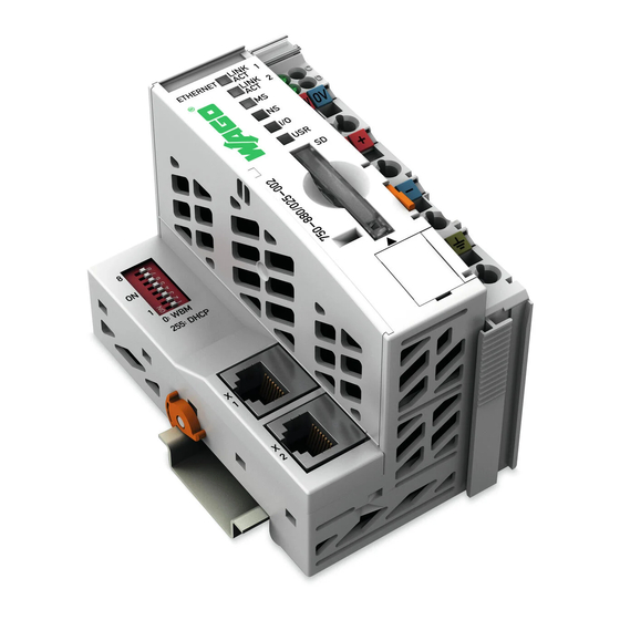
750-880
10/100 Mbit/s; digital and analog signals
Version 1.0.0
Pos : 3 /Alle Serien (Allgemeine M odule) /Hinweise zur Dokumentati on/Impres sum für Standardhandbüc her - allg. Ang aben, Anschriften, Tel efonnummer n und E-Mail-Adress en @ 3\mod_1219151118203_21.doc @ 21060 @ @ 1
Advertisement
Chapters
Table of Contents

Related Manuals for WAGO I/O System 750


Summary of Contents for WAGO I/O System 750
- Page 1 Pos : 2 /D okumentati on allgemein/Ei nband/Ei nband H andbuch - Dec kbl att ohne Variantenfel d (Standar d) @ 9\mod_1285229289866_0.doc @ 64941 @ @ 1 Quickstart Reference WAGO-I/O-SYSTEM 750 ETHERNET Programmable Fieldbus 750-880 10/100 Mbit/s; digital and analog signals Version 1.0.0...
- Page 2 WAGO-I/O-SYSTEM 750 750-880 ETHERNET Programmable Fieldbus © 2012 by WAGO Kontakttechnik GmbH & Co. KG All rights reserved. WAGO Kontakttechnik GmbH & Co. KG Hansastraße 27 D-32423 Minden Phone: +49 (0) 571/8 87 – 0 Fax: +49 (0) 571/8 87 – 1 69 E-Mail: info@wago.com...
-
Page 3: Table Of Contents
Configuring a Communication Driver for a USB Link ......44 4.7.1 Starting the Program ................46 Visualization ................... 47 4.8.1 Opening Visualization via the WAGO-I/O-PRO Software ....47 4.8.2 Opening Web Visualization in the Internet Browser ......48 4.8.3 Operating the Visualization ..............49 List of Figures ...................... -
Page 4: Notes About This Documentation
Notes about this Documentation Pos : 8 /Seri e 750 ( WAGO-I/O- SYSTEM)/Hi nweise zur D okumentati on/Gültig keitsbereic h D okumentati on Koppl er/Contr oller 750- xxxx, ohne Variantenangabe @ 4\mod_1239095911562_21.doc @ 30110 @ 2 @ 1 Validity of this Documentation This documentation is only applicable to the 750-880 ETHERNET Programmable Fieldbus of the WAGO-I/O-SYSTEM 750 series. -
Page 5: Symbols
WAGO-I/O-SYSTEM 750 Notes about this Documentation 750-880 ETHERNET Programmable Fieldbus Pos : 9.3 /Alle Serien (Allgemeine M odule) /Übersc hriften für alle Serien/Hi nweis zur D okumentati on/Symbole - Übersc hrift 2 @ 13\mod_1351068042408_21.doc @ 105270 @ 2 @ 1 Symbols Pos : 9.4.1 /Alle Serien (Allgemeine M odule)/Wic htige Erl äuter ungen/Sic her heits- und s ons tige Hi nweis e/Gefahr/Gefahr: _War nung vor Pers onensc häden allgemein_ - Erläuter ung @ 13\mod_1343309450020_21.doc @ 101029 @ @ 1... - Page 6 Notes about this Documentation WAGO-I/O-SYSTEM 750 750-880 ETHERNET Programmable Fieldbus Additional Information: Refers to additional information which is not an integral part of this documentation (e.g., the Internet). Pos : 9.5 /D okumentati on allgemein/Gliederungsel emente/---Seitenwechsel--- @ 3\mod_1221108045078_0.doc @ 21810 @ @ 1 Quickstart Reference Version 1.0.0...
-
Page 7: Number Notation
WAGO-I/O-SYSTEM 750 Notes about this Documentation 750-880 ETHERNET Programmable Fieldbus Pos : 9.6 /Alle Serien (Allgemeine M odule) /Hinweise zur Dokumentati on/Z ahl ens ysteme @ 3\mod_1221059454015_21.doc @ 21711 @ 2 @ 1 Number Notation Table 1: Number Notation Number code... -
Page 8: Important Notes
All changes to the coupler or controller should always be carried out by qualified personnel with sufficient skills in PLC programming. Pos : 12.5 /Serie 750 (WAGO-I/O-SYST EM)/Wic htige Erläuterungen/Bes timmungsgemäß e Ver wendung 750- xxxx @ 3\mod_1224064151234_21.doc @ 24070 @ 3 @ 1 2.1.3... -
Page 9: Technical Condition Of Specified Devices
The components to be supplied Ex Works, are equipped with hardware and software configurations, which meet the individual application requirements. WAGO Kontakttechnik GmbH & Co. KG will be exempted from any liability in case of changes in hardware or software as well as to non-compliant usage of components. -
Page 10: Safety Advice (Precautions)
Pos : 12.10.2 /Serie 750 ( WAGO-I/O- SYST EM)/Wic htig e Erl äuter ung en/Sic her hei ts- und s onstige Hi nwei se/Gefahr/Gefahr: Einbau 0750- xxxx nur i n Gehäus en, Schr änken oder elektrischen Betriebsräumen! @ 6\mod_1260180556692_21.doc... - Page 11 WAGO-I/O-SYSTEM 750 Important Notes 750-880 ETHERNET Programmable Fieldbus Do not use any contact spray! Do not use any contact spray. The spray may impair contact area functionality in connection with contamination. Pos : 12.11.5 /Alle Serien (Allgemeine M odul e)/Wichtige Erläuter ung en/Sic her heits- und s onstige Hinweise/Ac htung/Ac htung: Verpolung ver mei den! @ 6\mod_1260184045744_21.doc @ 46767 @ @ 1...
-
Page 12: Quickstart Description
Quickstart Description Pos : 15 /Serie 750 ( WAGO-I/O-SYST EM)/Ger ätebesc hrei bung/Ei nlei tung/Fel dbus koppl er/-c ontroller/Einl eitender Text/Quic kstart/Starter Kit 750-0880: Aufbau der H ardware Ü 2 und Ei nleitung @ 13\mod_1348142899039_21.doc @ 103066 @ 2 @ 1... -
Page 13: Table 4: Legend To The View Ethernet Tcp/Ip Fieldbus Controller
750-880 ETHERNET Programmable Fieldbus Pos : 17 /Serie 750 ( WAGO-I/O-SYST EM)/Ger ätebesc hrei bung/Ansic ht/Fel dbus koppl er/-contr oller/Leg ende/Ansic ht - Legende z ur Ansicht SETH ERNET (750- 880,881,882) - Tabellenkopf und Nr: 1 @ 7\mod_1266415064861_21.doc @ 50950 @ @ 1... -
Page 14: Figure 2: Mode Selector Switch (Closed And Open Damper Of The Service Port)
Pos : 24 /Serie 750 ( WAGO-I/O-SYST EM)/Ger ätebesc hrei bung/Ei nlei tung/Fel dbus koppl er/-c ontroller/Einl eitender Text/Quic kstart 750-088x: Hi nweis: Betriebsartensc hal ter i n die ober e Stellung schalten! @ 9\mod_1287492632163_21.doc @ 65716 @ @ 1... -
Page 15: Figure 3: (1) Open The Memory Card Slot, (2) Insert The Sd Card
750-880 ETHERNET Programmable Fieldbus Pos : 26 /Serie 750 ( WAGO-I/O-SYST EM)/Ger ätebesc hrei bung/Ei nlei tung/Fel dbus koppl er/-c ontroller/Einl eitender Text/Quic kstart/Starter Kit 750-0880: Speicher karte @ 13\mod_1348217984343_21.doc @ 103159 @ @ 1 Only use recommended memory cards! Only use the SD memory card available from WAGO (Item No. -
Page 16: Preparatory Measures
Pos : 29 /Serie 750 ( WAGO-I/O-SYST EM)/Ger ätebesc hrei bung/Ei nlei tung/Fel dbus koppl er/-c ontroller/Einl eitender Text/Quic kstart/Starter Kit 750-088x: D okumentati on und Beis piel proj ekte her unterl aden @ 13\mod_1348215563298_21.doc... -
Page 17: Figure 5: Contents Of The Wago-I/O-Pro Cd (Folder View), Setup.exe File
Insert the WAGO-I/O-PRO CD into your CD-ROM drive. If the installation does not begin automatically, start the file Setup.exe. Figure 5: Contents of the WAGO-I/O-PRO CD (folder view), Setup.exe file Select the language. Then confirm this selection by clicking [OK]. -
Page 18: Figure 7: Starting The Setup
Quickstart Description WAGO-I/O-SYSTEM 750 750-880 ETHERNET Programmable Fieldbus Click the [Next] button in order to start setup using the "InstallShield Wizard". Figure 7: Starting the setup Click on the [OK] button in order to accept the license agreement. Figure 8: License agreement Quickstart Reference Version 1.0.0... -
Page 19: Figure 9: Selecting The Target Directory
WAGO-I/O-SYSTEM 750 Quickstart Description 750-880 ETHERNET Programmable Fieldbus Select the target directory. Then confirm this selection by clicking [Next]. Figure 9: Selecting the target directory Select the components to be installed. Then confirm this selection by clicking [Next]. Figure 10: Selection of components Quickstart Reference Version 1.0.0... -
Page 20: Figure 11: Selection Of Program Folder
Quickstart Description WAGO-I/O-SYSTEM 750 750-880 ETHERNET Programmable Fieldbus Select the program folder. Then confirm this selection by clicking [Next]. Figure 11: Selection of program folder Check the settings you have defined. Then confirm this selection by clicking [Next]. Figure 12: Overview of configuration Quickstart Reference Version 1.0.0... -
Page 21: Figure 13: Pdf Document "Ea_Configurationreleaseinfo.pdf
WAGO-I/O-SYSTEM 750 Quickstart Description 750-880 ETHERNET Programmable Fieldbus This opens the pdf document "EA_ConfigurationReleaseInfo.pdf", which has information about the new version of the WAGO-I/O Configurator dialog. Figure 13: Pdf document "EA_ConfigurationReleaseInfo.pdf" Click [Complete] to end setup. Figure 14: Completing the setup Quickstart Reference Version 1.0.0... -
Page 22: Starting Up The Ethernet Network
Quickstart Description WAGO-I/O-SYSTEM 750 750-880 ETHERNET Programmable Fieldbus 3.2.3 Starting Up the ETHERNET Network This section provides you with a step-by-step sample procedure for starting up the ETHERNET network. You must perform three steps to start up the network: •... -
Page 23: Determine The Ip Address Of Your Pc And Change It If Required
WAGO-I/O-SYSTEM 750 Quickstart Description 750-880 ETHERNET Programmable Fieldbus 3.2.3.1 Determine the IP address of your PC and change it if required The explanation below describes how to determine the IP address currently set for your PC and how to change it if required. -
Page 24: Figure 16: Properties Of The Tcp/Ip Internet Protocol
Quickstart Description WAGO-I/O-SYSTEM 750 750-880 ETHERNET Programmable Fieldbus Check whether the current IP address is set within the address range 192.168.1.1 to 192.168.1.254. If not, change it accordingly. Do not use IP address 192.168.1.100! Do not use the IP address 192.168.1.100, however, as this network address is reserved for the fieldbus controller in the present example. -
Page 25: Assigning An Ip Address To The Fieldbus Controller
• BootP or • WAGO ETHERNET settings. The option for using the address selection switch is detailed in this QuickStart Guide. The other options are not described here, as these are explained completely in the manual for the "750-880 ETHERNET Programmable Fieldbus Controller". -
Page 26: Figure 17: Address Selection Switch With Set Ip Address (192.168.1.100)
Quickstart Description WAGO-I/O-SYSTEM 750 750-880 ETHERNET Programmable Fieldbus Values 0 and 255 are predefined! Set the values 0 or 255 using the address selection switch. This activates the IP modes provided. When a value of 0 is set, the IP configurations executed by WebBasedManagement will apply. -
Page 27: Testing The Ethernet Link
WAGO-I/O-SYSTEM 750 Quickstart Description 750-880 ETHERNET Programmable Fieldbus 3.2.3.3 Testing the ETHERNET link Open the command line interpreter by entering "cmd" at Start > Execute… in Windows. Figure 19: Dialog box "Execute .." Enter the command "ping 192.168.1.100." Figure 20: Command line interpreter with ping command... -
Page 28: Installing The Usb Driver
WAGO-I/O-SYSTEM 750 750-880 ETHERNET Programmable Fieldbus 3.2.4 Installing the USB Driver The "WAGO USB Service Cable" (Item No.: 750-923) provides a simple option for communication with WAGO software tools (WAGO-ETHERNET-Settings, WAGO-I/O-CHECK 3, etc.) and with the IEC-61131 programming topology (WAGO-O/O-PRO). -
Page 29: Figure 24: Finishing The Installation
WAGO-I/O-SYSTEM 750 Quickstart Description 750-880 ETHERNET Programmable Fieldbus Click on the [OK] button to finish the installation. Figure 24: Finishing the Installation Plug the USB cable into an available USB port on your PC. Pos : 33 /D okumentation allgemei n/Glieder ungs elemente/---Seitenwec hs el--- @ 3\mod_1221108045078_0.doc @ 21810 @ @ 1 Quickstart Reference Version 1.0.0... -
Page 30: Application Example: Starterkit880_App1_Fup.pro
750-880 ETHERNET Programmable Fieldbus Pos : 34 /Serie 750 ( WAGO-I/O-SYST EM)/Ger ätebesc hrei bung/Ei nlei tung/Fel dbus koppl er/-c ontroller/Einl eitender Text/Quic kstart/Starter Kit 750-0880: Besc hrei bung - T eil 2 @ 13\mod_1348581883530_21.doc @ 103418 @ 12222223232333 @ 1 Application example: Starterkit880_App1_FUP.pro... -
Page 31: Open Project
Start WAGO-I/O-PRO: Start > All Programs > WAGO-Software > CoDeSys > CoDeSys V2.3 > CoDeSys V2.3. In the WAGO-I/O-PRO software, select File > Open ... in the menu and open the CoDeSys project "Starterkit880_App1_FUB.pro". Configure hardware Select PLC configuration in the tree structure in the Resources tab in order to access hardware configuration. -
Page 32: Figure 27: Plc Configuration - Add Sub-Module
Application example: Starterkit880_App1_FUP.pro WAGO-I/O-SYSTEM 750 750-880 ETHERNET Programmable Fieldbus Select K-Bus in the tree structure. Then right-click to open the context menu and select Add sub-module. You can change the current PLC configuration. Figure 27: PLC Configuration – Add sub-module Select the Inputs/Outputs tab in the "I/O Configurator"... -
Page 33: Figure 29: Plc Configuration - Select I/O Modules
WAGO-I/O-SYSTEM 750 Application example: Starterkit880_App1_FUP.pro 750-880 ETHERNET Programmable Fieldbus In the left window, select the I/O modules based on your hardware setup. Click on the [>>] button to add the selected modules. Figure 29: PLC configuration – Select I/O modules... -
Page 34: Figure 30: Plc Configuration - Assign Variables
Assign corresponding variables to the digital input/output modules in the right window of the I/O Configurator. This symbolic name will then be available as a global variable in the overall WAGO-I/O-PRO project. The variables are structured as follows: symbolic name, IEC address, data type, associated comments. -
Page 35: Main Program "Plc_Prg
WAGO-I/O-SYSTEM 750 Application example: Starterkit880_App1_FUP.pro 750-880 ETHERNET Programmable Fieldbus Main Program "PLC_PRG" Select the object PLC_PRG in the Modules tab in order to open the main program. You will see the variable declaration in the upper part of the dialog box. The individual FUB networks are displayed in the lower part. -
Page 36: Subprogram "Blink
Application example: Starterkit880_App1_FUP.pro WAGO-I/O-SYSTEM 750 750-880 ETHERNET Programmable Fieldbus You can activate the first digital output using a bistable function block "rsDO1" applying RS logic (reset = dominant). The "SET" input of the "rsDO1" function block is linked to a flank-detecting function block "ftrigDO1", which detects the falling flank for "xVisuDO1". -
Page 37: Figure 34: Blink Signal
WAGO-I/O-SYSTEM 750 Application example: Starterkit880_App1_FUP.pro 750-880 ETHERNET Programmable Fieldbus A pulsing signal is generated in the "Blink" subprogram. This blink signal "tofBlink2.Q" is required for the flashing frame around the buttons in the display. The pulse period for this signal is 800 ms, which corresponds to a frequency of 1.25 Hz. -
Page 38: Subprogram "Userled
USR-LED signaling and about using the "Visual.lib", the corresponding library description will be of assistance. The help file for this description is located in the WAGO-I/O-PRO directory: WAGO Software > CoDeSys V2.3 > Targets > WAGO > Help > German > CAA- WAGO_Visual.chm. Quickstart Reference... -
Page 39: Figure 38: Network 1 (Usr-Led)
WAGO-I/O-SYSTEM 750 Application example: Starterkit880_App1_FUP.pro 750-880 ETHERNET Programmable Fieldbus In the first network, the address operator "ADR" supplies the address for the variable "aFS" and stores this in the pointer variable "ptFS." The individual blinking sequences for the USR-LED (LED colors) are defined by the array variables "aFS."... -
Page 40: Figure 41: Network 4 (Usr-Led)
Application example: Starterkit880_App1_FUP.pro WAGO-I/O-SYSTEM 750 750-880 ETHERNET Programmable Fieldbus The function "START_FLASHING_SEQUENCE" starts the sequences set previously using the function "SET_FLASHING_SEQUENCE." Index 0 (USR- LED = green) is executed first, as the variable "wIndex" was initialized with this value in the variable declaration. -
Page 41: Figure 43: Network 6 (Usr-Led)
WAGO-I/O-SYSTEM 750 Application example: Starterkit880_App1_FUP.pro 750-880 ETHERNET Programmable Fieldbus In the sixth Network, the visualization button [USR-LED] is assigned a color as a function of "wIndex." This ensures that the [USR-LED] button has the same color in the display as the physical USR-LED for the fieldbus controller. This value is assigned via a multiplexer (MUX). -
Page 42: Commissioning
750-880 ETHERNET Programmable Fieldbus Commissioning The following section provides a step-by-step description of how to load the WAGO-I/O-PRO project "Starterkit880_App1_FUB.pro" to your fieldbus controller, how to start program execution, and how to create a boot project. 4.6.1 Configuring a Communication Driver for an ETHERNET... -
Page 43: Figure 46: New Communication Channel Via Ethernet
WAGO-I/O-SYSTEM 750 Application example: Starterkit880_App1_FUP.pro 750-880 ETHERNET Programmable Fieldbus Enter a name for the ETHERNET link in the Name field. Select the "Tcp/Ip 3S Tcp/Ip driver" and confirm your input by clicking [OK]. Figure 46: New communication channel via ETHERNET Double-click on the address field localhost in the column "Value"... -
Page 44: Configuring A Communication Driver For A Usb Link
Start > Control panel > System > Device manager. Add the group Ports (COM and LPT) to the tree structure. The entry WAGO USB Service Cable (COMX) is given within this group. The designation in parentheses indicates the assigned COM port; in this example "COM3". -
Page 45: Figure 49: New Communication Channel Via Usb
WAGO-I/O-SYSTEM 750 Application example: Starterkit880_App1_FUP.pro 750-880 ETHERNET Programmable Fieldbus Select the driver "Serial (RS232) 3S Serial RS232 driver" and confirm your input by clicking [OK]. Figure 49: New communication channel via USB Double-click on the address field COM1 in the column "Value" in the "Communication parameters"... -
Page 46: Starting The Program
Application example: Starterkit880_App1_FUP.pro WAGO-I/O-SYSTEM 750 750-880 ETHERNET Programmable Fieldbus 4.7.1 Starting the Program Click Login in the Online menu to load this program to your fieldbus controller. Then start program execution in the fieldbus controller via the menu item Online > Start. -
Page 47: Visualization
Visualization Two options are available for visualization operation: • You can directly control the visualization via the WAGO-I/O-PRO software after you have loaded and started the program on the fieldbus controller. • You can also call up and control the process in an Internet browser as a Web visualization. -
Page 48: Opening Web Visualization In The Internet Browser
Application example: Starterkit880_App1_FUP.pro WAGO-I/O-SYSTEM 750 750-880 ETHERNET Programmable Fieldbus 4.8.2 Opening Web Visualization in the Internet Browser Enter the IP address for your fieldbus controller (192.168.1.100) in the address line of your browser. You are then transferred to WebBasedManagement for your fieldbus controller. -
Page 49: Operating The Visualization
WAGO-I/O-SYSTEM 750 Application example: Starterkit880_App1_FUP.pro 750-880 ETHERNET Programmable Fieldbus 4.8.3 Operating the Visualization Actuatable buttons in the visualization are indicated by a blinking frame. In addition, your mouse pointer changes when you move it over these buttons. Hovering for a short period will call up a yellow box, in which you can read the button function. -
Page 50: List Of Figures
Figure 3: (1) Open the memory card slot, (2) insert the SD card ......15 Figure 4: Download possibilities at the WAGO homepage ........16 Figure 5: Contents of the WAGO-I/O-PRO CD (folder view), Setup.exe file ..17 Figure 6: Selecting the setup language ..............17 Figure 7: Starting the setup ................... - Page 51 Figure 50: USB communication parameters ............45 Figure 51: Operating mode switch in RUN position ..........46 Figure 52: Visualization via WAGO-I/O-PRO software ........47 Figure 53: Web visualization with an Internet browser ........48 Pos : 37 /D okumentation allgemei n/Glieder ungs elemente/---Seitenwec hs el--- @ 3\mod_1221108045078_0.doc @ 21810 @ @ 1 Quickstart Reference Version 1.0.0...
-
Page 52: List Of Tables
List of Tables WAGO-I/O-SYSTEM 750 750-880 ETHERNET Programmable Fieldbus Pos : 38 /D okumentation allgemei n/Verz eic hniss e/T abell enverz eichnis - ohne Glieder ung - und Verzeic hnis @ 3\mod_1219222958703_21.doc @ 21084 @ @ 1 List of Tables Table 1: Number Notation .................. - Page 53 WAGO-I/O-SYSTEM 750 750-880 ETHERNET Programmable Fieldbus Pos : 40 /D okumentation allgemei n/Einband/Einband H andbuc h - Leers eite für ger ade Sei tenz ahl @ 3\mod_1219230851078_0.doc @ 21123 @ @ 1 Quickstart Reference Version 1.0.0...
- Page 54 Pos : 41 /D okumentation allgemei n/Einband/Einband H andbuc h - R üc kseite @ 9\mod_1285229376516_21.doc @ 64944 @ @ 1 WAGO Kontakttechnik GmbH & Co. KG Postfach 2880 • D-32385 Minden Hansastraße 27 • D-32423 Minden Phone: +49/5 71/8 87 – 0 Fax: +49/5 71/8 87 –...
Need help?
Do you have a question about the I/O System 750 and is the answer not in the manual?
Questions and answers