Sign In
Upload
Manuals
Brands
WAGO Manuals
I/O Systems
I/O System 750 Series
User Manuals: WAGO I/O System 750 Series Modules
Manuals and User Guides for WAGO I/O System 750 Series Modules. We have
5
WAGO I/O System 750 Series Modules manuals available for free PDF download: Manual
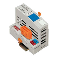
WAGO I/O System 750 Series Manual (130 pages)
Modular I/O System
Brand:
WAGO
| Category:
I/O Systems
| Size: 1 MB
Table of Contents
Table of Contents
3
1 Important Notes
6
Legal Principles
6
Copyright
6
Personnel Qualification
6
Conforming Use of Series 750
7
Technical Condition of the Devices
7
Standards and Regulations for Operating the 750 Series
7
Symbols
8
Safety Information
9
Font Conventions
10
Number Notation
10
Scope
10
Abbreviation
11
2 The WAGO-I/O-SYSTEM 750
12
System Description
12
Technical Data
13
Manufacturing Number
16
Component Update
17
Storage, Assembly and Transport
18
Mechanical Setup
18
Installation Position
18
Total Expansion
18
Assembly Onto Carrier Rail
19
Carrier Rail Properties
19
WAGO DIN Rail
20
Spacing
20
Plugging and Removal of the Components
21
Assembly Sequence
22
Internal Bus / Data Contacts
23
Power Contacts
24
Wire Connection
25
Power Supply
26
Isolation
26
System Supply
27
Connection
27
Alignment
28
Field Supply
30
Connection
30
Fusing
31
Supply Example
34
Power Supply Unit
35
Grounding
36
Grounding the DIN Rail
36
Framework Assembly
36
Insulated Assembly
36
Grounding Function
37
Grounding Protection
38
Shielding (Screening)
39
General
39
Bus Conductors
39
Signal Conductors
39
WAGO Shield (Screen) Connecting System
40
Assembly Guidelines / Standards
40
3 Fieldbus Coupler
42
Description
43
Hardware
44
View
44
Device Supply
45
Fieldbus Connection
45
Display Elements
46
Configuration Interface
47
Hardware Address (MAC ID)
47
Setting the Baud Rate
48
Operating System
48
Process Image
49
Data Exchange
50
Communication Interfaces
51
Memory Areas
51
Addressing
52
Fieldbus Specific
52
Configuration Software
54
Starting up Devicenet Fieldbus Nodes
54
Connecting the PC and Fieldbus Node
54
Setting the MAC ID and Baud Rate
54
Configuration with Static Assembly
55
LED Display
59
Node Status - Blink Code from the 'I/O' LED
60
Technical Data
67
Description
68
Network Architecture
69
Transmission Media
69
Type of Cable
69
Cable Types
69
Maximum Bus Length
70
Cabling
70
Network Topology
72
Network Grounding
73
Interface Modules
73
Network Communication
74
Objects, Classes, Instances and Attributes
74
Module Characteristics
75
Communication Model
75
Message Groups
75
Message Types
75
I/O Messaging Connections
76
Process Data and Diagnostic Status
76
Process Image
76
Wago-I/O-System
76
Assembly Instances
77
Configuration / Parametering with the Object Model
79
EDS Files
79
Object Model
80
Object Model for Coupler 750-346
81
5 O Modules
98
Overview
98
Digital Input Modules
98
Digital Output Modules
100
Analog Intput Modules
101
Analog Output Modules
102
Special Modules
103
System Modules
104
Process Data Architecture for Devicenet
105
Digital Input Modules
105
Digital Output Modules
107
Analog Input Modules
111
Analog Output Modules
113
Specialty Modules
114
System Modules
126
6 Glossary
127
7 Literature List
128
8 Index
129
Advertisement
WAGO I/O System 750 Series Manual (64 pages)
SMI Master Module 230 V AC
Brand:
WAGO
| Category:
Control Unit
| Size: 3 MB
Table of Contents
Table of Contents
3
1 Notes about this Documentation
5
Validity of this Documentation
5
Copyright
5
Symbols
6
Number Notation
8
Font Conventions
8
Table 1: Number Notation
8
Table 2: Font Conventions
8
2 Important Notes
9
Legal Bases
9
Subject to Changes
9
Personnel Qualifications
9
Use of the WAGO-I/O-SYSTEM 750 in Compliance with Underlying Provisions
9
Technical Condition of Specified Devices
10
Disposal
10
Safety Advice (Precautions)
11
3 Device Description
13
Table 3: Compatibility List 753-1630 - Full Mode
14
Table 4: Compatibility List 753-1630 - Fieldbus Coupler Mode
15
View
16
Figure 1: View of Device
16
Table 5: Legend for Figure "View
16
Connectors
17
Data Contacts/Local Bus
17
Figure 2: Data Contacts
17
Power Jumper Contacts/Field Supply
18
Figure 3: Power Jumper Contacts
18
Table 6: Legend for Figure "Power Jumper Contacts
18
CAGE CLAMP ® Connectors
19
Function Earth
19
Figure 4: CAGE CLAMP ® Connections
19
Table 7: Legend for "CAGE CLAMP ® Connections" Figure
19
Display Elements
20
Figure 5: Display Elements
20
Table 8: Legend for the "Display Elements" Figure
20
Schematic Diagram
21
Figure 6: Schematic Circuit Diagram
21
Technical Data
22
Device Data
22
Power Supply
22
Table 9: Technical Data - Device
22
Table 10: Technical Data - Power Supply
22
Communication
23
Table 11: Technical Data - Communication
23
Table 12: Technical Data - Field Wiring
23
Climatic Environmental Conditions
24
Table 13: Technical Data - Climatic Environmental Conditions
24
Approvals
25
Standards and Guidelines
26
4 Function Description
27
Fieldbus Coupler Mode
27
Digital Input
28
1-Button Operation/Construction Site Mode
28
Forced Position
29
2-Button Operation
29
Positioning Curtains and Slats
30
Table 14: Behavior of SMI Drives and Curtains with Button Presses
30
Figure 7: Schematic Representation of the Positioning of Shutters and Slats
31
Table 15: Legend for the Figure "Schematic Representation of the Positioning of Shutters and Slats
31
Controller Locking
32
Energy Saving Mode
32
Activating the Energy Saving Function Via Timeout
32
Activating the Energy Saving Function Via Control Byte C1
33
Digital Output
33
Local Bus Failure Monitoring
34
Controller Failure Monitoring
34
Power Failure Monitoring
34
Automatic Addressing
35
Auto-Replace
35
Full Mode
37
System Extensions
37
Switching Addresses and Readdressing
37
Logging
38
Reading the System Image
38
Extended SMI Command Set
38
5 Process Image
39
Control/Status Byte
40
Table 16: Control Byte C0
40
Table 17: Status Byte S0
40
Extended Control/Status Byte
41
Table 18: Control Byte C1
41
Table 19: Status Byte S1
41
Fieldbus Coupler Mode
42
Output and Input Process Image
42
Table 20: Output and Input Process Image in Fieldbus Coupler Mode
42
Addressing SMI Drives
43
SMI Commands
44
Table 21: SMI Commands
44
Table 22: Response to Request Commands
45
Full Mode
46
6 Mounting
47
Mounting Sequence
47
Inserting and Removing Devices
49
Inserting the I/O Module
49
Figure 8: Insert I/O Module (Example)
49
Figure 9: Snap the I/O Module into Place (Example)
49
Removing the I/O Module
50
Figure 10: Removing the I/O Module (Example)
50
I/O Modules with Pluggable Wiring Level (Series 753)
51
Figure 11: Plug and I/O Module
51
Figure 12: Assignment of I/O Module to Plug Using Mini-WSB Tags
51
Coding
52
Figure 13: Attachment of Cable Binders
52
Figure 14: Assembling the Coding Fingers
52
Figure 15: Inserting the Coding Fingers
52
Figure 16: Plugging the Plug into Place
53
Figure 17: "Sure Match" Coding Fingers
53
Plug Removal
54
Figure 18: Pulling the Pull Tab
54
Figure 19: Removing the Plug Without Tools
54
Figure 20: Removing the Plug Using a Screwdriver
54
7 Connect Devices
55
Connecting a Conductor to the CAGE CLAMP
55
Figure 21: Connecting a Conductor to a CAGE CLAMP
55
Connection Examples
56
Figure 22: Connection Example - 2-Wire Connection
56
Figure 23: Connection Example - 2-Wire Connection for Energy Saving Mode
56
8 Commissioning
57
Preparation
57
Table 23: Example of a Fieldbus Node Setup
57
Configuration and Parameterization
58
IEC Function Block Library CODESYS 2.3
58
E!Cockpit
58
WAGO SMI Configurator
59
9 Diagnostics
60
Table 24: Overview of the Diagnostics and Status Messages of the
60
List of Figures
62
List of Tables
63
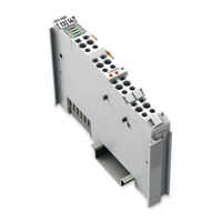
WAGO I/O System 750 Series Manual (50 pages)
2 AI ±10 V DC, Differential inputs 2-Channel Analog Input Module ±10 V
Brand:
WAGO
| Category:
I/O Systems
| Size: 4 MB
Table of Contents
Deutsch
3
Table of Contents
3
1 Notes about this Documentation
5
Validity of this Documentation
5
Copyright
5
Symbols
6
Number Notation
8
Font Conventions
8
Table 1: Number Notation
8
Table 2: Font Conventions
8
2 Important Notes
9
Legal Bases
9
Subject to Changes
9
Personnel Qualifications
9
Use of the WAGO-I/O-SYSTEM 750 in Compliance with Underlying Provisions
9
Technical Condition of Specified Devices
10
Safety Advice (Precautions)
11
3 Device Description
13
View
14
Table 3: Legend for Figure "View
14
Connectors
15
Data Contacts/Internal Bus
15
Power Jumper Contacts/Field Supply
15
CAGE CLAMP ® Connectors
16
Table 4: Legend for Figure "CAGE CLAMP ® Connectors
16
Display Elements
18
Operating Elements
18
Table 5: Legend for Figure "Display Elements" 753-456
18
Schematic Diagram
19
Technical Data
20
Device Data
20
Power Supply
20
Communication
20
Inputs
20
Table 6: Technical Data - Device
20
Table 7: Technical Data - Power Supply
20
Table 8: Technical Data - Communication
20
Table 9: Technical Data, Inputs
20
Connection
21
Climatic Environmental Conditions
21
Table 10: Technical Data - Field Wiring
21
Table 11: Technical Data - Data Contacts
21
Table 12: Technical Data - Climatic Environmental Conditions
21
Approvals
22
Standards and Guidelines
24
4 Process Image
25
Table 13: Process Image
26
5 Mounting
27
Mounting Sequence
27
Inserting and Removing Devices
28
Inserting the I/O Module
28
Removing the I/O Module
29
I/O Modules with Pluggable Wiring Level (Series 753)
30
Coding
32
Figure 15: "Sure Match" Coding Fingers
33
Plug Removal
34
6 Connect Devices
35
Connecting a Conductor to the CAGE CLAMP
35
Connection Examples
36
7 Use in Hazardous Environments
37
Marking Configuration Examples
38
Marking for Europe According to ATEX and Iecex
38
Table 14: Description of Marking Example According to ATEX and Iecex
39
Marking for America (NEC) and Canada (CEC)
41
Table 15: Description of Marking Example for Approved Ex I I/O Module According to ATEX and Iecex
41
Table 16: Description of Marking Example According to NEC 500
42
Table 17: Description of Marking Example for Approved Ex I I/O Module
43
Table 18: Description of Marking Example for Approved Ex I I/O Modules
43
Table 19: Description of Marking Example for Approved Ex I I/O Modules
44
Installation Regulations
45
Special Notes Regarding Explosion Protection
45
Special Notes Regarding ANSI/ISA Ex
47
English
48
Figure 1: View
14
Figure 2: Data Contacts
15
Figure 3: CAGE CLAMP ® Connectors
16
Figure 4: Display Elements
18
Figure 5: Schematic Diagram
19
Figure 6: Insert I/O Module (Example)
28
Figure 7: Snap the I/O Module into Place (Example)
28
Figure 8: Removing the I/O Module (Example)
29
Figure 10: Assignment of I/O Module to Plug Using Mini-WSB Tags
30
Figure 9: Plug and I/O Module
30
Figure 11: Attachment of Cable Binders
31
Figure 12: Assembling the Coding Fingers
32
Figure 13: Inserting the Coding Fingers
32
Figure 14: Plugging the Plug into Place
32
Figure 16: Pulling the Pull Tab
34
Figure 17: Removing the Plug Without Tools
34
Figure 18: Removing the Plug Using a Screwdriver
34
Figure 19: Connecting a Conductor to a CAGE CLAMP
35
Figure 20: Connection Example 753-456
36
Figure 21: Marking Example According to ATEX and Iecex
38
Figure 22: Text Detail - Marking Example According to ATEX and Iecex
38
Figure 23: Marking Example for Approved Ex I I/O Module According to ATEX and Iecex
40
Figure 24: Text Detail - Marking Example for Approved Ex I I/O Module According to ATEX and Iecex
40
Figure 25: Marking Example According to NEC
42
Figure 26: Text Detail - Marking Example According to NEC 500
42
Figure 27: Text Detail - Marking Example for Approved Ex I I/O Module
43
Figure 28: Text Detail - Marking Example for Approved Ex I I/O Module
43
Figure 29: Text Detail - Marking Example for Approved Ex I I/O Modules
44
List of Figures
48
List of Tables
49
Advertisement
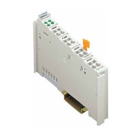
WAGO I/O System 750 Series Manual (58 pages)
Fieldbus Independent I/O Modules, Incremental Encoder Interfaces
Brand:
WAGO
| Category:
I/O Systems
| Size: 0 MB
Table of Contents
Table of Contents
3
1 Important Notes
5
Legal Bases
5
Copyright
5
Personnel Qualifications
5
Use of the 750 Series in Compliance with Underlying Provisions
6
Technical Condition of Specified Devices
6
Standards and Guidelines for Operating the 750 Series
7
Symbols
8
Safety Information
9
Font Conventions
10
Number Notation
10
Scope
11
2 O Modules
12
Special Modules
12
Overview Incremental Encoder Interfaces 750-631 (/XXX-XXX)
12
Variations
13
View
13
Description
13
Incremental Encoder Interface]
13
Display Elements
14
Schematic Diagram
15
Technical Data
16
Functional Description
17
Process Image
18
750-631/000-004 [Incremental Enc./ RS422]
21
View
21
Description
21
Display Elements
22
Schematic Diagram
23
Technical Data
24
Functional Description
26
Process Image
27
Variations
31
View
31
Description
31
Display Elements
33
Schematic Diagram
34
Technical Data
35
Functional Description
37
Process Image
38
Connection Variations
42
Incremental Encoder with RS422 Output (Variation A)
42
Incremental Encoder with 24 V Push-Pull Output (Variation
42
Incremental Encoder with Non-Equivalent 24 V Push-Pull Output (Variation C)
43
Incremental Encoder with 5 V Push-Pull Output (Variation
43
3 Use in Hazardous Environments
44
Marking Configuration Examples
45
Marking for Europe According to CENELEC and IEC
45
Marking for America According to NEC 500
48
Installation Regulations
49
Special Conditions for Safe Operation of the ATEX and IEC Ex (Acc. DEMKO 08 ATEX 142851X and Iecex PTB 07.0064)
50
Special Conditions for Safe Use (ATEX Certificate TÜV 07 ATEX 554086 X)
51
Special Conditions for Safe Use (IEC-Ex Certificate TUN 09.0001
53
Special Conditions for Safe Use (ATEX Certificate DEKRA 11ATEX0203 X)
55
Ansi/Isa 12.12.01
56
WAGO I/O System 750 Series Manual (14 pages)
Fieldbus Independent I/O Modules 1 AI DMS
Brand:
WAGO
| Category:
I/O Systems
| Size: 0 MB
Table of Contents
Table of Contents
3
1 Important Comments
4
Legal Principles
4
Copyright
4
Personnel Qualification
4
Intended Use
4
Symbols
5
Number Notation
5
Safety Notes
6
Scope
6
2 O Modules
7
Digital Output Modules
7
750-491 [1 Ai Dms]
7
Variations
7
View
7
Description
8
Display Elements
9
Schematic Diagram
9
Technical Data
10
Process Image
11
Applicaton Examples
12
Connection Examples
13
Advertisement
Related Products
WAGO I/O SYSTEM 750
WAGO I/O System 750 XTR
WAGO INTERBUS S
WAGO WAGO-I/O-SYSTEM750 Series
WAGO IP 350
WAGO WAGO-I/O-SYSTEM 750 Series
WAGO I/O System 753
WAGO 50-1418
WAGO 750 Series
WAGO 750-1402
WAGO Categories
I/O Systems
Control Unit
Power Supply
Switch
Controller
More WAGO Manuals
Login
Sign In
OR
Sign in with Facebook
Sign in with Google
Upload manual
Upload from disk
Upload from URL