Sign In
Upload
Manuals
Brands
Sirona Manuals
Medical Equipment
ORTHOPHOS SL 2D
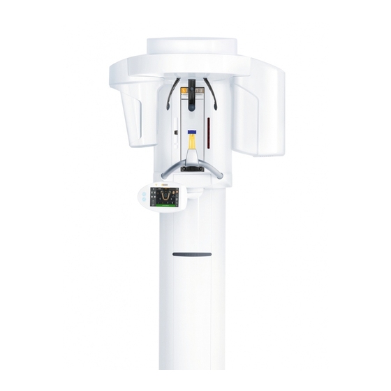
Sirona ORTHOPHOS SL 2D Manuals
Manuals and User Guides for Sirona ORTHOPHOS SL 2D. We have
2
Sirona ORTHOPHOS SL 2D manuals available for free PDF download: Service Manual, Installation Manual
Sirona ORTHOPHOS SL 2D Service Manual (472 pages)
Brand:
Sirona
| Category:
Medical Equipment
| Size: 29.63 MB
Table of Contents
Table of Contents
3
About this Service Manual
13
Other Relevant Documents
13
Scope
13
Tools and Auxiliary Materials
13
Structure of the Document
14
Identification of the Danger Levels
14
Formats and Symbols Used
14
Safety Instructions
15
Potentially Lethal Shock Hazard
15
Modifications to the Unit
15
Fixed Connection
15
Electromagnetic Compatibility
15
Electrostatic Discharge
16
Switching the Unit on
16
Condensation
16
Laser Light Localizer
16
Ventilation Slots
16
Qualifications of Service Personnel
16
Radiation Protection
17
Safety Checks
17
Functional Check
17
Unit Description
18
Hardware
18
Information on the Unit
18
System Version
19
Sensor Versions
20
Installation Versions
21
Modules and Components
22
Slide
23
Stand
24
Cephalometer
25
Remote Control
25
Cabling Overview
26
Board Photos
30
Boards in the Slide
30
Boards in the Cephalometer
36
Boards in the Stand
36
Board in the Remote Control
37
Covers
37
Technical Data
40
Unit Data
40
Operating and Transport Conditions
42
Diagrams
43
Requirements for the PC System
44
Firmware
45
General Operating Procedures
47
Switching the Unit on
47
Factory Setting after Switch-On
48
Setting up the X-Ray Component
49
Opening / Saving "Unit Information
59
Activating Functions
62
Activation Via Easypad
62
Activation Via PC
64
D3632
64
Updating the Unit Firmware
68
Backing up / Restoring / Installing Sensor Data
71
Access the "Backup / Restore Sensor Data" Menu
71
Backing up Sensor Data
73
Restoring Sensor Data
74
Installing Sensor Data
75
Calling the Info Screen
76
Using Demo Mode - Operation Without Radiation Release
77
Switching on Demo Mode
77
Switching off Demo Mode
78
Important Information for Repacking and Transport
79
Messages
80
Help Messages
80
Status Displays
81
Error Messages
82
Error Code: Ex Yy Zz
82
Ex - Error Type
82
Yy - Location
83
General Handling of Error Messages
83
List of Error Messages
84
Location 06: Tube Assembly/Dx6
84
Location 07: Easypad/Dx7
90
Location 10: System Hardware
93
Location 11: Power Pc/Board DX11
94
Location 12: CAN Bus
96
Location 13: Stand/Peripherals
97
Location 14: Digital Extension, SIDEXIS 4
110
Location 15: Configuration, Update
112
Location 20: Sensor Unit, General
113
Location 22: DCS Sensor
118
Location 23: Flat Panel Detector
119
Location 42: Remote Control
120
Location 61: Diaphragm Control, Board DX61
124
Location 81, Board DX81, Ceph Slot
130
Location 83: Sensor Unit
134
Location 91: Cephalometer, Board DX91
135
Troubleshooting
139
Error Logging Memory
139
Example of Error Logging Data
140
Checking the CAN Bus
141
Checking the CAN Bus with the Diagnostic Function of Board DX1
145
Jumper Positions in the CAN Bus
145
Checking the Boards
146
Checking Board DX32
148
Checking the Motors
150
Checking the Light Barriers
151
Device Leakage Current too High
152
Checking the Cables
153
Checking Fiber-Optic Cables
154
Error Analysis of X-RAY Control Signal Path
156
Checking the Data Paths
159
Unit Adjustment and Calibration
160
General Information on Unit Adjustment and Calibration
162
Displays and Help Messages During Adjustment and Calibration
163
Calibration Menu
164
Opening the Calibration Menu
164
Menu Structure
166
Enabling Exposure Readiness
175
Taking an Exposure
175
Save Values
175
Test Phantom for Adjustment and Calibration
176
Needle Phantom for Panoramic Adjustment
176
Adjustment Phantom for Adjustment of the Cephalometer
178
Geometry Phantom for Volume Calibration
179
Adjustment and Calibration Via the Calibration Menu
181
2D Adjustment/Calibration
181
Pan Sensor Adjustment
181
Pan Aperture Adjustment
187
Pan Symmetry Adjustment
193
Pan Sensor Calibration (DCS)
197
Adjustment of the Ceph Primary Diaphragm
199
Adjustment of the Ceph Secondary Diaphragm
204
Adjustment of the Ceph Secondary Diaphragm
212
Adjustment of the Ceph Main X-Ray Beam
217
Adjusting the Earplug Alignment
221
3D Adjustment/Calibration
226
Sensor Adjustment
226
Diaphragm Adjustment
228
Sensor Calibration
229
Diaphragm Configuration
230
Geometry Calibration
232
Dosimetry
234
Resetting Adjustment/Calibration
235
Adjusting the Touchscreen Via the Web Service
236
Service Routines
240
Perform Service Routines Via the Control Panel
240
Overview of Service Routines
240
List of All Service Routines Available for Selection
240
Alphabetical List of Service Routine Functions
243
Service Menu and Service Routines
246
Displays and Symbols in the Service Menu
246
Basic Operating Procedures in the Service Menu of the Control Panel
248
Calling the Service Menu
248
Selecting Service Routines and Test Steps
249
Saving Parameters
251
Select Parameters
251
Exiting the Test Step and Service Routine
252
S001: Radiation Without Rotary Movement, Fixed Maximum Radiation Time
253
S002: Radiation Without Rotary Movement, Selectable Kv/Ma Level 255 and Maximum Radiation Time 8.1.5.1 S002: Test Step 1
255
S002: Test Step 3
256
S002: Test Step 4
258
S005: General X-Ray Tube Assembly Service
260
S005: Test Step 2
260
S005: Test Step 4
261
S005: Test Step 5
262
S005: Test Step 6
262
S005: Test Step 7
264
S007: Fault Buffer
265
S007: Test Step 1
265
S007: Test Step 2
266
S008: Update Service
267
S008: Test Step 2
267
S008: Test Step 3
267
S009: Flash File System
268
S009: Test Step 4
268
S009: Test Step 5
268
S011: Dosimetry (Without Ring Movement)
269
S011: Test Step 14
269
S011: Test Step 24
271
S012: CAN Bus Service
272
S012: Test Step 1
272
S012: Test Step 2
273
S012: Test Step 3
274
S012: Test Step 4
274
S014: Rotation Motor Service
275
S014: Test Step 3
275
S014: Test Step 4
275
S015: Actuator Service
276
S015: Test Step 5
276
S017: Configuration Service
277
S017: Test Step 2
278
S017: Test Step 3
281
S017: Test Step 4
282
S017: Test Step 6
283
S017: Test Step 8
284
S017: Test Step 13
285
S017: Test Step 14
286
S017: Test Step 15
287
S017: Test Step 18
288
S018: Service for Height Adjustment
289
S018: Test Step 2
289
S018: Test Step 3
290
S018: Test Step 4
291
S018: Test Step 5
292
S018: Test Step 6
292
S018: Test Step 7
293
S018: Test Step 8
295
S018: Test Step 9
297
S018: Test Step 10
299
S020: Service for Temple Support
300
S020: Test Step 1
300
S021: Service for the Packing Position
302
S021: Test Step 3
302
S021: Test Step 4
303
S032: Sensor Test
304
S032: Test Step 10
304
Explanations on the Test Procedure
305
S032: Test Step 50
305
Possible Results of Self-Test and Troubleshooting Measures
306
S033: Test of Ceph Image Path (for Ceph Units Only)
307
S033: Test Step 10
307
S034: Service for the Digital Cephalometer
309
S034: Test Step 4
309
S034: Test Step 5
313
S034: Test Step 6
316
S034: Test Step 8
317
S034: Test Step 9
318
S037: Network Service
320
S037: Test Step 1
320
S037: Test Step 2
322
S037: Test Step 3
323
S037: Test Step 4
324
Running Service Routines Via the Web Service
327
Repair
330
Safety Checks
331
Height Adjustment Motor (M1_4)/Spindle
332
Preparing for Motor Replacement
332
Moving the Slide Manually
332
Removing Board DX32
335
Replacing the Height Adjustment Motor/Spindle
337
Laying of Cables When Replacing the Height Adjustment Motor
339
What Has to be Done after Replacing the Height Adjustment Motor
341
Ring Motor (M1_3)
342
Replacing the Ring Motor
342
Replacing the Pinion at the Ring Motor
342
Laying of Cables When Replacing the Ring Motor
344
What Has to be Done after Replacing the Ring Motor (M1_3)/Pinion
344
Pan Actuators (M1_1/2)
345
Replacing Actuators
345
Laying of Cables When Replacing the Actuator
346
What Has to be Done after Replacing the Actuators
346
Head Support
347
Replacing the Headrest
347
Laying of Cables When Replacing the Headrest
348
What Has to be Done after Replacing the Headrest
348
Control Panel
349
Replacing the User Interface
349
What Has to be Done after Replacing the User Interface
350
Replacing the Control Panel
351
What Has to be Done after Replacing the Control Panel
352
Laying Cables for Control Panel Replacement
352
Laser Light Localizers
353
FH Laser Light Localizer (Pan)
353
Replacing the Laser Module in the FH (Pan) Laser Light
353
Adjusting the Laser Light Localizer FH (PAN)
354
FH Laser Light Localizer (Ceph)
356
Replacing the Ceph Laser Module in the FH Laser Light
356
Adjusting the FH Laser Light Localizer (Ceph)
357
MS Laser Light Localizer (Pan)
359
Replacing the Laser Module in the MS Laser Light Localizer
359
Adjusting the MS Laser Light Localizer (PAN)
360
Laser Area Display (VOL)
362
Replacing the Laser Area Display (VOL)
362
Adjusting the Laser Area Display (VOL)
364
Checking the Connection of the MS and FH (Pan) Laser Light
366
Occlusal Bite Block
367
Replacing the Occlusal Bite Block
367
What Has to be Done after Replacing the Occlusal Bite Block
367
Bite Block Holder
368
Replacing the Bite Block Holder
368
Replacing the Silicone Rings
369
What Has to be Done after Replacing the Bite Block Holder / Silicone
369
Diaphragm Unit
370
Replacing the Diaphragm Unit
370
What Has to be Done after Replacing the Diaphragm Unit
371
X-Ray Tube Unit
372
Replacing the X-Ray Tube Assembly
372
Replacing the Fan in the X-Ray Tube Assembly
374
Replacing the Fan
374
What Has to be Done after Replacing the Fan
374
Cables and Connectors for Replacement of the X-Ray Tube Assembly
375
What Has to be Done after Replacing the X-Ray Tube Assembly
377
Sensor Unit
378
Flat Panel Detector
378
Replacing the Flat Panel Detector
378
Connecting a Sensor Unit
380
What Has to be Done after Replacing the Flat Panel
381
DCS Sensor
382
Replacing the DCS Sensor
382
Connecting a Sensor Unit
384
What Has to be Done after Replacing the DCS Sensor
385
Replace Board DX83
386
Replacing Fan Package
390
Cephalometer
391
Replacing the Ceph Sensor Holder
391
What Has to be Done after Replacing the Ceph Sensor
391
Replacing the Ceph Sensor
392
What Has to be Done after Replacing the Ceph Sensor
392
Light Barriers
393
Replacing the Light Barriers
393
What Has to be Done after Replacing the Light Barriers
394
Boards
395
Important Notes about Replacing Boards
395
Replacing Boards
396
Replacing PC Board DX1
396
Replacing Board DX11
397
Replacing Board DX32
397
After Changing the DX11 Board
398
Measures Following Replacement of Boards
398
Cable
400
Replacing Energy Chain 1 Completely
400
Replacing Cables
404
Replacing Fiber-Optic Cable L5, L6 or L15
405
Cable Exchange (L3, L5, L6, L11, L12, and L15)/Laying
406
The Cable/Corrugated Tube at the Rotation Unit
406
Replacing Cable L117 or L108 in Cable Track 2
408
Replacing Cable L1 or Grounding Strap in Cable Track 1
410
Maintenance
411
Calibrating the Unit
411
Checking the Height Adjustment
412
Checking the Forehead and Temple Supports
413
Check Rotation Unit on the Sensor Unit for Ease of Access
414
Testing the Rotating Unit for Smooth Running
414
Inspecting the Bite Block Holder
415
Checking the Ceph Sensor Holder
416
Checking the Laser Light Localizers
417
Checking the X-Ray Images
420
Checking the Tube Data
421
Checking the Tube Voltage
421
Checking the Tube Current
422
Checking the Fan and Temperature Sensor in the Tube Assembly
425
Checking the Radiation Time
426
Test Exposures/Test Images
427
Calling "Test Exposures" Menu
428
Test Exposures
429
Pan - Diaphragm Test Exposure (2D)
429
Pan - Symmetrical Test Exposure (2D)
430
Pan - Quality Test Exposure (2D)
431
Pan - Test Image (2D)
433
Pan - Dark Current Exposure (2D)
435
Ceph - Secondary Diaphragm (2D)
437
Ceph - Quality Test Exposure (2D)
438
Ceph - Test Image (2D)
441
Test Exposures
443
Diaphragm Test Exposure (Open) (3D)
443
Diaphragm Test Exposure (Collimated) (3D)
445
Diaphragm Test Exposure (Standard) (3D)
447
Quality Test Exposure (3D)
449
Quality Test Exposure DIN 6868-161 (3D)
451
Test Image (3D)
452
Dosimetry (3D)
454
Dosimetry DIN 6868-161 (3D)
455
Dark Current Exposure (3D)
456
Checking the Cables for Damage
458
Checking the Idling Rollers
459
Checking the Grounding Straps
460
Checking the Cable Shields
461
Checking the Protective Ground Wires
462
Checking the Device Leakage Current
466
Dismantling and Disposal
467
Dismantling and Reinstallation
467
Disposal
467
Service Manual History
469
Advertisement
Sirona ORTHOPHOS SL 2D Installation Manual (284 pages)
Brand:
Sirona
| Category:
Dental equipment
| Size: 22.6 MB
Table of Contents
Table of Contents
3
About These Installation Instructions
9
Structure of the Document
9
Identification of the Danger Levels
9
Formats and Symbols Used
10
Scope
11
Other Relevant Documents
11
Safety Instructions
12
Information on the Unit
12
Fixed Connection
12
Ventilation Slots
12
Condensation
13
Qualifications of Service Personnel
13
Switching the Unit on
13
Radiation Protection
13
Laser Light Localizer
13
Modifications to the Unit
14
Transport Safety Devices
14
Electromagnetic Compatibility
14
Electrostatic Discharge
14
Unit Description
15
System Version
15
Sensor Versions
17
Dimensions/Space Requirements
18
Top View
18
Front View
19
Top View with Floor Stand
20
Front View with Floor Stand
21
Top View with Ceph Left
22
Front View with Ceph Left
23
Top View with Ceph Right
24
Front View with Ceph Right
25
Mounting Options
26
Installation Versions
27
Delivery and Transport
28
Operating and Transport Conditions
28
Delivery
28
Orthophos Sl
30
Sensors
32
Ceph Arm
34
Accessories
35
Hygienic Protection
35
Adjustment Sets
36
Transport to the Installation Site
39
Orthophos Sl
39
Transport with Packaging Attached (Normal Case)
39
Transport Without Pallet (Exception)
40
Ceph Arm
41
Sensors
41
Installation: X-Ray Unit
42
Installation Material
42
Standard Version
42
Option 1: with Second Wall Holder
44
Option 2: Floor Stand Installation
45
Tools, Materials, and Measurement Tools You will Need
47
Tools and Materials
47
Measurement Tools
48
Wall Mounting (Standard and Option 1)
49
Installing the Floor Stand (Option 2)
55
Remove the Transport Safety Device
63
Installing Tube Assembly Cover
63
Installing the Release Button Holder
64
Installing the Sensor Unit
65
Required Tools
65
Installing the Sensor Cover on the Ring
66
Attaching DCS Sensor
67
Attaching Flat Panel Detector or Dummy Weight
68
Connecting a Sensor Unit
69
Final Installation Work
71
Installation: Remote Control
72
Installation Material
72
Required Tools
72
Installation
73
Connecting the Control Cables (REMOTE)
76
Installation Version 1: Without Coiled Cable
76
Installation Version 2: with Spiral Cable
77
Connecting the X-Ray Warning Lamp
78
Final Installation Work
79
Connecting a Door Contact Switch
80
Electrical Connection
81
Connecting the Control Cables
81
Connecting the Line Voltage
82
Connecting the Unit
82
Connecting the Media Converter
83
Safety Checks
84
Checking the Protective Ground Wires
84
Checking the Device Leakage Current
88
Installation: Ceph Arm
89
Installation Material
89
Required Tools
90
Installation
91
Ceph Arm Mounted on Left-Hand Side
91
Ceph Arm Mounted on Right-Hand Side
94
Installing the Secondary Diaphragm
98
Connecting Control Cables
99
Running the Cables for the Left-Hand Arm
101
Running the Cables for the Right-Hand Arm
101
Final Installation Work
102
Commissioning, Demo Mode and Repacking
104
Attaching the Covers
104
Inserting the Forehead and Temple Supports
105
Inserting the Ceph Sensor (for Ceph Versions)
105
Installing the IT Package
105
Switching the Unit on
106
Factory Setting after Switch-On
108
Performing a Mechanical Function Test
109
Starting the Test Cycle
109
Checking the Height Adjustment Mechanics
110
Configuring the Unit
111
Setting up the X-Ray Component
112
Checking the Data Paths
122
Setting Ambient Light Via the Web Service
123
Using Demo Mode - Operation Without Radiation Release
125
Switching on Demo Mode
125
Switching off Demo Mode
126
Important Information for Repacking and Transport
127
Service Routines for Commissioning and Repacking
129
Service Menu and Service Routines
130
1Displays and Symbols in the Service Menu
130
Basic Operating Procedures in the Service Menu of the Control Panel
132
1Calling the Service Menu
132
2Selecting Service Routines and Test Steps
133
3Select Parameters
135
4Saving Parameters
135
5Exiting the Test Step and Service Routine
136
S017: Configuration Service
137
1S017: Test Step 2
138
2S017: Test Step 3
140
3S017: Test Step 4
141
4S017: Test Step 6
142
5S017: Test Step 8
143
6S017: Test Step 13
144
7S017: Test Step 14
145
8S017: Test Step 15
146
9S017: Test Step 18
147
S018: Service for Height Adjustment
148
1S018: Test Step 2
149
2S018: Test Step 3
150
3S018: Test Step 4
151
4S018: Test Step 5
152
5S018: Test Step 6
152
6S018: Test Step 7
153
7S018: Test Step 8
155
8S018: Test Step 9
157
9S018: Test Step 10
159
S021: Service for the Packing Position
161
1S021: Test Step 3
161
2S021: Test Step 4
162
S032: Sensor Test
163
1S032: Test Step 10
163
2S032: Test Step 50
164
3Explanations on the Test Procedure
165
4Possible Results of Self-Test and Troubleshooting Measures
166
S037: Network Service
167
1S037: Test Step 1
167
2S037: Test Step 2
169
3S037: Test Step 3
170
4S037: Test Step 4
171
Running Service Routines Via the Web Service
174
Startup, Measurements and Tests (for Usa/Canada Only)
177
Safety
177
Operation Notes
178
Auxiliary Devices Required
179
Checking the Power Supply Connection
180
Checking the Tube Voltage
182
Checking the Radiation Time
183
Checking the Tube Current
184
Checking the Laser Light Localizers
188
Unit Adjustment and Calibration
191
General Information on Unit Adjustment and Calibration
193
Displays and Help Messages During Adjustment and Calibration
194
Calibration Menu
195
Opening the Calibration Menu
195
Menu Structure
197
Enabling Exposure Readiness
209
Taking an Exposure
209
Save Values
209
Test Phantom for Adjustment and Calibration
210
Needle Phantom for Panoramic Adjustment
210
Adjustment Phantom for Adjustment of the Cephalometer
212
Geometry Phantom for Volume Calibration
213
Adjustment and Calibration Via the Calibration Menu
215
2D Adjustment/Calibration
215
Pan Sensor Adjustment
215
Pan Aperture Adjustment
221
Pan Symmetry Adjustment
227
Pan Sensor Calibration (DCS)
231
Adjustment of the Ceph Primary Diaphragm
233
Adjustment of the Ceph Secondary Diaphragm
238
Adjustment of the Ceph Secondary Diaphragm (Quickshot)
247
Adjustment of the Ceph Main X-Ray Beam
253
Adjusting the Earplug Alignment
257
3D Adjustment/Calibration
262
Sensor Adjustment
262
Diaphragm Adjustment
264
Sensor Calibration
265
Diaphragm Configuration
266
Geometry Calibration
268
Dosimetry
270
Resetting Adjustment/Calibration
271
Adjusting the Touchscreen Via the Web Service
272
Final Work
276
Save Sensor Data
276
Opening "Unit Information
279
Filling in the Certificate of Conformity
282
Unit Handover
283
Advertisement
Related Products
Sirona Sinius CS
Sirona Sinius
Sirona sirolaser blue
Sirona ORTHOPHOS SL 3D
Sirona SIROLaser Advance
Sirona SIROInspect
Sirona S2
Sirona SIROLaser Xtend
Sirona orthophos xg 3
Sirona Orthophos XG 3D Ceph
Sirona Categories
Medical Equipment
Dental equipment
Accessories
Laboratory Equipment
Indoor Furnishing
More Sirona Manuals
Login
Sign In
OR
Sign in with Facebook
Sign in with Google
Upload manual
Upload from disk
Upload from URL