Sign In
Upload
Manuals
Brands
Sirona Manuals
Medical Equipment
Orthophos XG 3D Ceph
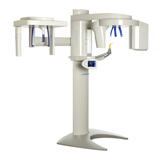
Sirona Orthophos XG 3D Ceph X-ray Machine Manuals
Manuals and User Guides for Sirona Orthophos XG 3D Ceph X-ray Machine. We have
1
Sirona Orthophos XG 3D Ceph X-ray Machine manual available for free PDF download: Service Manual
Sirona Orthophos XG 3D Ceph Service Manual (504 pages)
Brand:
Sirona
| Category:
Medical Equipment
| Size: 21.07 MB
Table of Contents
Table of Contents
3
About this Service Manual
13
Scope
13
Other Documentation Required
13
Tools and Auxiliary Materials
13
Structure of the Document
14
Identification of the Danger Levels
14
Formats and Symbols Used
14
Safety Instructions
15
Modifications to the Unit
15
Fixed Connection
15
Electromagnetic Compatibility
15
Electrostatic Discharge
15
Switching the Unit on
15
Condensation
16
Laser Light Localizer
16
Ventilation Slots
16
Qualifications of Service Personnel
16
Radiation Protection
16
Safety Checks
17
Functional Check
17
Unit Description
18
Hardware
18
Information on the Unit
18
System Versions
19
Sensor Versions
20
Installation Versions
21
Modules and Components
22
Slide
23
Stand
24
Cephalometer
25
Remote Control
25
Cabling Overview
26
Board Photos
32
Boards in the Slide
32
Boards in the Stand
39
Boards in the Cephalometer (Left- and Right-Arm Versions)
40
Board in the Remote Control
41
Covers
41
Technical Data
44
Firmware
49
General Operating Procedures
60
Switching the Unit on
60
Factory Setting after Switch-On
61
Updating the Unit Firmware
62
D3352
63
Update Mode
67
Check Program Releases
69
Opening "Details
71
Setup of an X-Ray Component
73
Selecting an X-Ray Component
74
Approval of the X-Ray Component
80
Deleting an X-Ray Component
82
Using Demo Mode - Operation Without Radiation Release
83
Switching on Demo Mode
83
Switching off Demo Mode
84
Important Information for Repacking and Transport
85
Messages
88
Help Messages
89
System Messages
90
Status Displays
90
Error Messages
91
Error Code: Ex Yy Zz
91
Ex - Error Type
91
Yy - Location
93
General Handling of Error Messages
93
List of Error Messages
94
Location 06: Tube Assembly/Dx6
94
Location 07: Easypad/Dx7
101
Location 10: System Hardware
105
Location 11: Power Pc/Board DX11
108
Location 12: CAN Bus
111
Location 13: Stand/Peripherals
111
Location 14: Digital Extension, SIDEXIS XG
125
Location 15: Configuration, Update
129
Location 42: Remote Control
131
Location 61: Diaphragm Control, Board DX61
135
Location 81, Zz=1-23: Board DX81, Pan Slot
142
Location 81, Zz=51-78: Board DX81, Ceph Slot
146
Location 88: Combisensor
150
Location 91: Cephalometer, Board DX91
155
Troubleshooting
160
Error Logging Memory
161
Example of Error Logging Data
161
Checking the CAN Bus
163
Checking the CAN Bus with the Diagnostic Function of Board DX1
167
Jumper Positions in the CAN Bus
168
Checking the Boards
169
Checking Board DX32
171
Checking the Motors
173
Checking the Light Barriers
174
Device Leakage Current too High
175
Checking the Cables
176
Error Analysis of X-RAY Control Signal Path
177
Checking the Data Paths
180
Creating 2D Test Images
180
Creating a 3D Test Image
182
Adjusting and Calibrating the Unit
184
General Information about Unit Adjustment and Calibration
186
Displays and Help Messages During Adjustment/Calibration
187
Adjustment/Calibration" Menu
188
Calling the "Adjustment/Calibration" Menu
188
Menu Structure
189
Enabling Exposure Readiness
197
Taking an Exposure
197
Save Values
197
Test Phantoms for Adjustment and Calibration
198
OP XG Needle Phantom for Panoramic Adjustment
198
OP XG 3D Ceph Adjustment Phantom for the Adjustment
200
Geometry Phantom for Volume Calibration
201
Adjustment and Calibration Via the "Unit Adjustment/Calibration" Menu
203
2D Adjustment
203
Pan Sensor Adjustment
203
Pan Diaphragm
206
Pan Symmetry
210
Ceph - Primary Diaphragm
214
Ceph - Fixed Point of Rotation
218
Ceph - Main X-Ray Beam Direction
222
Ceph - Fixed Point of Rotation for Quickshot
225
Ear Plug Alignment
229
Adjustment/Calibration
234
Sensor
234
Aperture
235
Shading
237
Shading (5X5)
238
Geometry
239
Dosimetry
240
Saving Adjustment/Calibration Data
241
Resetting Adjustment/Calibration
242
Checking and Adjusting the Touchscreen
244
Mechanical Adjustments
246
Mechanical Adjustment: Ceph Secondary Diaphragm
246
Perform Service Routines Via the Control Panel
248
Overview of Service Routines
248
List of All Service Routines Available for Selection
248
Alphabetical List of Service Routine Functions
251
Service Menu and Service Routines
254
Displays and Symbols in the Service Menu
254
Easypad
254
Basic Operating Procedures in the Service Menu
256
Activating the Service Menu
256
Easypad
256
Selecting Service Routines and Test Steps
258
Selecting a Service Routine
258
Selecting a Test Step
258
Service Routines with Security Access
259
Select Parameters
261
Saving Parameters
262
Exiting the Test Step and Service Routine
262
S001: Radiation Without Rotary Movement, Fixed Maximum Radiation Time
263
Maximum Radiation Time
263
S002: Test Step 3
267
S002: Test Step 4
269
S002: Test Step 5
271
S005: General X-Ray Tube Assembly Service
272
S005: Test Step 1
272
S005: Test Step 2
274
S005: Test Step 4
275
S005: Test Step 5
276
S005: Test Step 6
276
S005: Test Step 7
278
S007: Error Logging Memory
280
S007: Test Step 1
280
S007: Test Step 2
282
S007: Test Step 5
283
Displaying the Log with a Web Browser
284
S008: Update Service
286
S008: Test Step 2
286
S008: Test Step 3
287
S009: Flash File System
288
S009: Test Step 4
288
S009: Test Step 5
289
S009: Test Step 8
290
S011: Dosimetry (Without Ring Movement)
291
S011: Test Step 14
291
S011: Test Step 24
293
S012: CAN Bus Service
294
S012: Test Step 1
294
S012: Test Step 2
296
S012: Test Step 3
297
S012: Test Step 4
298
S014: Rotation Motor Service
299
S014: Test Step 1
299
S014: Test Step 2
300
S014: Test Step 3
301
S014: Test Step 4
301
S015: Actuator Service
302
S015: Test Step 5
302
S017: Configuration Service
303
S017: Test Step 2
304
S017: Test Step 3
307
S017: Test Step 4
308
S017: Test Step 5
309
S017: Test Step 6
311
S017: Test Step 8
312
S017: Test Step 12
313
S017: Test Step 13
314
S017: Test Step 14
315
S017: Test Step 15
317
S017: Test Step 17
318
S017: Test Step 18 (Occlusal Bite Block Only)
321
S017: Test Step 21
323
S018: Service for Height Adjustment
324
S018: Test Step 2
325
S018: Test Step 3
326
S018: Test Step 4
327
S018: Test Step 5
328
S018: Test Step 6
329
S018: Test Step 7 (Occlusal Bite Block Only)
330
S018: Test Step 8 (Occlusal Bite Block Only)
332
Codes of Possible Error Modes
333
S018: Test Step 9 (Occlusal Bite Block Only)
334
S018: Test Step 10 (Occlusal Bite Block Only)
336
S020: Service for Temple Support
337
S020: Test Step 1
337
S021: Service for Motor-Driven Diaphragm
339
S021: Test Step 1
339
S032: Sensor Test
341
S032: Test Step 10
341
S032: Test Step 10: Explanations on the Test Procedure
343
S032: Test Step 10: Result of Synchronized Readout
343
Possible Results of Self-Test and Troubleshooting Measures
344
S032: Test Step 50
344
S032: Test Step 56
345
S033: Test of Ceph Image Path Without SIDEXIS XG (for Ceph Units Only)
346
S033: Test Step 10
346
S034: Service for the Digital Cephalometer
348
S034: Test Step 4
348
S034: Test Step 5
352
S034: Test Step 6
355
S034: Test Step 8
356
S034: Test Step 9
358
S037: Network Service
360
S037: Test Step 1
360
S037: Test Step 2
362
S037: Test Step 3
364
S037: Test Step 4
365
Repair
368
Safety Checks
369
Height Adjustment Motor (M1_4)/Spindle
370
Preparing for Motor Replacement
370
Moving the Slide Manually
370
Removing Board DX32
374
Replacing the Height Adjustment Motor/Spindle
376
Laying of Cables When Replacing the Height Adjustment Motor
378
What Has to be Done after Replacing the Height Adjustment Motor
380
Ring Motor (M1_3)
381
Replacing the Ring Motor
381
Replacing the Pinion at the Ring Motor
382
Laying of Cables When Replacing the Ring Motor
383
What Has to be Done after Replacing the Ring Motor (M1_3)/Pinion
383
Pan Actuators (M1_1/2)
384
Replacing Actuators
384
Laying of Cables When Replacing the Actuator
385
What Has to be Done after Replacing the Actuators
385
Head Support
386
Replacing the Headrest
386
Laying of Cables When Replacing the Headrest
387
What Has to be Done after Replacing the Headrest
387
Control Panel
388
Replacing the User Interface
388
What Has to be Done after Replacing the User Interface
389
Replacing the Control Panel
390
What Has to be Done after Replacing the Control Panel
391
Laying Cables for Control Panel Replacement
391
Laser Light Localizers
392
FH Double Laser Light Localizer (Pan)
392
Replacing the Laser Module in the FH Double Laser Light
392
Adjusting the FH Double Laser Light Localizer (PAN)
393
FH Laser Light Localizer (Ceph)
395
Replacing the Ceph Laser Module in the FH Laser Light
395
Adjusting the FH Laser Light Localizer (Ceph)
396
MS Laser Light Localizer (Pan)
398
Replacing the Laser Module in the MS Laser Light Localizer
398
Adjusting the MS Laser Light Localizer (PAN)
399
Occlusal Bite Block
401
Replacing the Occlusal Bite Block
401
What Has to be Done after Replacing the Occlusal Bite Block
401
Bite Block Holder
402
Replacing the Bite Block Holder
402
Replacing the Silicone Rings
403
What Has to be Done after Replacing the Bite Block Holder/Silicone
403
Diaphragm Unit
404
Replacing the Diaphragm Unit
404
What Has to be Done after Replacing the Diaphragm Unit
405
X-Ray Tube Unit
406
Replacing the X-Ray Tube Assembly
406
Cables and Connectors for Replacement of the X-Ray Tube Assembly
408
What Has to be Done after Replacing the X-Ray Tube Assembly
410
Fan (X-Ray Tube Assembly)
412
Replacing the Fan (Tube Assembly 1.0)
412
Replacing the Fan (Tube Assembly 2.0)
413
What Has to be Done after Replacing the Fan
414
Combisensor
415
Replacing the Rotation Unit
415
Replacing the 3D Module
417
What Has to be Done after Replacing the 3D Module
420
Replacing the 2D Sensor (Pan)
421
What Has to be Done after Replacing the 2D Sensor (Pan)
423
Cephalometer
424
Replacing the Ceph Sensor Holder
424
What Has to be Done after Replacing the Ceph Sensor
424
Replacing the Ceph Sensor
425
What Has to be Done after Replacing the Ceph Sensor
425
Light Barriers
426
Replacing the Light Barriers
426
What Has to be Done after Replacing the Light Barriers
427
Boards
428
Important Notes about Replacing Boards
428
Replacing Boards
429
Replacing PC Board DX1
430
Replacing Board DX11
431
Replacing Board DX32
431
Measures Following Replacement of Boards
432
After Changing the DX11 Board
435
Cable
437
Replacing Energy Chain 1 Completely
437
Replacing Cables
441
Replacing Fiber-Optic Cable L5, L6 or L15
441
Cable Exchange (L3, L5, L6, L11, L12, and L15)/Laying the Cable/Corrugated Tube at the Rotation Unit
442
Replacing Cable L117 or L108 in Cable Track 2
444
Replacing Cable L1 or Grounding Strap in Cable Track 1
446
Maintenance
447
Calibrating the Unit
447
Checking the Height Adjustment
448
Checking the Forehead and Temple Supports
449
Checking the Rotation Unit of the Combisensor for Smooth and Easy Running
450
Testing the Rotating Unit for Smooth Running
450
Inspecting the Bite Block Holder
451
Checking the Ceph Sensor Holder
452
Checking the Laser Light Localizers
453
Checking the X-Ray Images
457
Checking the Tube Data
458
Checking the Tube Voltage
458
1Checking the Tube Voltage Characteristic During Exposure
458
2Testing the Tube Voltage (Tube Assembly 2.0)
463
Checking the Tube Current
464
Checking the Radiation Time
467
Checking the Fan and Temperature Sensor
468
Test Exposures/Test Images
469
Test Exposures
470
1Panoramic Diaphragm Test Exposure (2D)
470
2Pan - Symmetry Test Exposure (2D)
472
3Ceph - Fixed Point of Rotation Test Exposure (2D)
475
4Quality Test Exposure (2D)
477
Test Pattern
478
3D Test Exposures
480
1Diaphragm Test Exposure (3D)
480
2Quality Test Exposure (3D)
484
3Sensor Test Image (3D)
485
4Dosimetry (3D)
487
5Dark Current Exposure (3D)
488
Checking the Cables for Damage
490
Checking the Idling Rollers
491
Checking the Grounding Straps
492
Checking the Cable Shields
493
Checking the Protective Ground Wires
494
Checking the Device Leakage Current
499
Dismantling and Disposal
500
Dismantling and Reinstallation
500
Disposal
500
Service Manual History
502
Advertisement
Advertisement
Related Products
Sirona orthophos xg 3
Sirona ORTHOPHOS XG 5
Sirona ORTHOPHOS XG 5 Ceph
Sirona inEos X5
Sirona Orthophos XG 5 DS
Sirona orthophos 3 ceph
Sirona Orthophos XG Plus DS/Ceph
Sirona ORTHOPHOS XGPlus DS Ceph
Sirona ORTHOPHOS PlusDS Ceph
Sirona Orthophos XG 3D/Ceph
Sirona Categories
Medical Equipment
Dental equipment
Laboratory Equipment
Indoor Furnishing
Accessories
More Sirona Manuals
Login
Sign In
OR
Sign in with Facebook
Sign in with Google
Upload manual
Upload from disk
Upload from URL