
Related Manuals for Thermo Scientific appliedbiosystems SeqStudio Flex Series


Summary of Contents for Thermo Scientific appliedbiosystems SeqStudio Flex Series
- Page 1 ™ SeqStudio Flex Series Genetic Analyzer with Instrument Software v1.0 USER GUIDE Catalog Numbers A50369 Publication Number 100104689 Revision A For Research Use Only. Not for use in diagnostic procedures.
- Page 2 Life Technologies Holdings Pte Ltd | Block 33 | Marsiling Industrial Estate Road 3 | #07-06, Singapore 739256 For descriptions of symbols on product labels or product documents, go to thermofisher.com/symbols-definition. The information in this guide is subject to change without notice. DISCLAIMER: TO THE EXTENT ALLOWED BY LAW, THERMO FISHER SCIENTIFIC INC.
-
Page 3: Table Of Contents
Contents ■ CHAPTER 1 Product information ..........16 Product description . - Page 4 Contents ■ CHAPTER 2 Get started ............53 Sign in .
- Page 5 Contents ■ CHAPTER 5 Create a plate file in the Plate Manager software ....95 Options for creating plate files in the Plate Manager software ..... . . 95 Get started with the Plate Manager software (desktop) .
- Page 6 Contents Run plates with the automated barcode workflow ....... . . 147 Create the plate files before the barcoded plates are loaded into the drawer .
- Page 7 Contents Cancel injections or specify re-injections in the Remote Monitoring software ..192 Pause the instrument from the Remote Monitoring screen, resume from the instrument home screen ..........193 Monitor a run from a mobile device .
- Page 8 Contents Basic voice commands ........... . 234 Interactive voice command—start run .
- Page 9 Contents Run modules library ............272 Run module overview .
- Page 10 Contents Example spatial profiles ........... 308 Export spatial calibration results or report .
- Page 11 Contents Change and store a capillary array (wizards) ........371 Parts of the capillary array .
- Page 12 Contents Manage settings ............. . 452 Display instrument hardware and software information .
- Page 13 Contents Run self tests to check touchscreen, speakers, microphone, and proximity sensor ............485 Power off or power on the instrument .
- Page 14 Contents ■ APPENDIX B Run modules and dye sets ........526 Run modules, read lengths, size ranges, and run times .
- Page 15 Contents Safety and electromagnetic compatibility (EMC) standards ......554 Safety standards ............555 EMC standards .
-
Page 16: Chapter 1 Product Information
Product information ■ Product description ..............16 ■... -
Page 17: Precautions For Use
Chapter 1 Product information Product description IMPORTANT! The protection provided by the equipment may be impaired if the instrument is operated outside the environment and use specifications, the user provides inadequate maintenance, or the equipment is used in a manner not specified by the manufacturer (Thermo Fisher Scientific). IMPORTANT! Observe current good clinical and laboratory practices when using this instrument. -
Page 18: Instrument Components
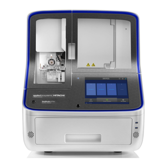
Chapter 1 Product information Product description Instrument components Figure 1 Parts of the instrument Pump compartment USB ports Microphones Touchscreen On/Off Blue LED Proximity sensor Capillary array, detection cell, detection cell heater, and oven compartment Speakers Drawer compartment SeqStudio ™ Flex Series Genetic Analyzer with Instrument Software v1.0 User Guide... - Page 19 Chapter 1 Product information Product description Part Function Pump compartment (see Figure 2 on page 21 for a detailed figure of the pump compartment) Anode buffer container Contains 1X running buffer to support all electrophoresis applications on the (ABC) instrument. Has a built-in overflow chamber to maintain constant fluid height. Polymer delivery pump Pumps polymer into the array and allows for automated maintenance procedures.
- Page 20 Chapter 1 Product information Product description (continued) Part Function Radio frequency RFID tags on the following primary instrument consumable labels are detected by identification (RFID) tags read/write units in the instrument interior: (not shown in figure) • Capillary array For more information, •...
-
Page 21: Instrument Interior Components
Chapter 1 Product information Product description Instrument interior components Figure 2 and Figure 3 are provided below for reference in this section. See also page 376 and “Parts of the capillary array” on page 372. Figure 2 Instrument interior (includes the pump compartment and capillary array compartment) Polymer delivery pump (PDP) Capillary array Water trap waste container... -
Page 22: Power And Communication Connections
Chapter 1 Product information Product description Figure 3 Detection cell heater with the door open and a capillary array installed. The detection cell in the capillary array is shown in the red box. Power and communication connections Figure 4 Instrument front panel connections USB ports used for transferring data SeqStudio ™... -
Page 23: Theory Of Operation
Chapter 1 Product information Theory of operation Figure 5 Instrument rear panel connections Recessed USB port (for use with the wireless Wired network port network adapter; adapter not shown) Circuit breaker (rear power switch; use the power switch on USB port (for optional USB barcode scanner the front panel for normal operation) connection) -
Page 24: During A Run
Chapter 1 Product information Materials for routine operation During a run During a run, the instrument: • Prepares the capillaries by pumping fresh polymer under high pressure from the polymer delivery pump to the waste position in the cathode buffer container (CBC). •... -
Page 25: Instrument Consumables Handling, Usage Limits, And Expiration
Chapter 1 Product information Instrument consumables handling, usage limits, and expiration Instrument consumables handling, usage limits, and expiration IMPORTANT! Before handling chemicals, read and understand all applicable Safety Data Sheets (SDSs) and use appropriate personal protective equipment (gloves, gowns, eye protection, etc). To obtain SDSs, see Appendix G, “Documentation and support”. -
Page 26: Buffer Storage, Usage, And Limits
Chapter 1 Product information Instrument consumables handling, usage limits, and expiration Buffer storage, usage, and limits Cat. No. Description Storage 4393927 Anode Buffer Container 3500/Flex Series (ABC), 4 pack 2–8°C Contains 1X running buffer 4408256 Cathode Buffer Container 3500/Flex Series (CBC), 4 pack 2–8°C Contains 1X running buffer See the expiration date on the label. -
Page 27: Conditioning Reagent Storage, Usage, And Limits
Chapter 1 Product information Instrument consumables handling, usage limits, and expiration Note: A polymer pouch includes a small reserve volume that is used for the Remove Bubbles maintenance wizard, which consumes ~350 μL of polymer. The reserve volume is sufficient to run the wizard ~4 times (including the remove bubbles step during other maintenance wizards). -
Page 28: Hi-Di ™ Formamide Storage And Usage
Chapter 1 Product information About the SeqStudio ™ Flex Series Instrument Software v1.0 Hi‑Di ™ Formamide storage and usage Formamide is an injection solvent that is used to prepare samples. It is not a consumable that is installed on the instrument as are the other consumables listed in this section. It does not include an RFID tag on the label. -
Page 29: Profile And Sign In Options
Chapter 1 Product information About the SeqStudio ™ Flex Series Instrument Software v1.0 • Optional use with the Security, Audit, and E-Signature (SAE) module for controlled user access • Application programming interface (API) to allow automation of instrument and software functions Profile and sign in options The profile you use to sign in depends on your instrument configuration. - Page 30 Chapter 1 Product information About the SeqStudio ™ Flex Series Instrument Software v1.0 2. In the User Profile screen, tap Get Started. Note: If SAE Sign in is displayed instead of Sign in, see “Sign in to the instrument with SAE enabled”...
- Page 31 Chapter 1 Product information About the SeqStudio ™ Flex Series Instrument Software v1.0 4. Tap Name, enter a local profile name, then tap Done. 5. Tap PIN (4 digits required), enter a four-digit numerical PIN, then tap Enter. 6. Tap Confirm PIN, reenter the PIN, then tap Enter. 7.
- Page 32 Chapter 1 Product information About the SeqStudio ™ Flex Series Instrument Software v1.0 2. In the User Profile screen, tap the down arrow under Sign in, then select your profile. 3. Tap the PIN field, enter your PIN, then tap Sign in. The home screen is displayed with your user initials (for example, ) in place of (Profile).
- Page 33 Chapter 1 Product information About the SeqStudio ™ Flex Series Instrument Software v1.0 Switch user or sign out 1. Tap the profile icon for the signed-in user (for example, ). ( indicates no user is signed in.) 2. In the My Profile screen, tap either of the following buttons: •...
- Page 34 Chapter 1 Product information About the SeqStudio ™ Flex Series Instrument Software v1.0 Sign in (if another user is signed in) 1. In the home screen, tap the profile icon for the signed-in user (for example, 2. In the My Profile screen, tap either of the following buttons: •...
-
Page 35: Parts Of The Software
Chapter 1 Product information About the SeqStudio ™ Flex Series Instrument Software v1.0 3. Tap your profile, then enter your PIN. The home screen is displayed with your user initials. For more information, see “Local profile and cloud profile: when to use, user name, and user initials”... - Page 36 Chapter 1 Product information About the SeqStudio ™ Flex Series Instrument Software v1.0 Parts of the home screen Icon bar—See “Icon bar” on page Plate positions—See “Plate positions in the home screen” on page Actions, drawer status, and Run queue—See “Actions, drawer status, and Run queue in the home screen” on page Instrument conditions—See “Instrument conditions in the home screen”...
- Page 37 Chapter 1 Product information About the SeqStudio ™ Flex Series Instrument Software v1.0 Icon bar Instrument name and signed-in user name. Pause indicator and Resume run button—Resume run is displayed after you click Pause instrument or if the instrument is paused because of an error condition.
- Page 38 Chapter 1 Product information About the SeqStudio ™ Flex Series Instrument Software v1.0 Plate positions in the home screen Plate position and status Time remaining or Estimated end time Glowing border on a completed plate position. Sample QC (or Spectral QC or Install QC) for the plate Plate alerts Plate name Run status...
- Page 39 Chapter 1 Product information About the SeqStudio ™ Flex Series Instrument Software v1.0 (continued) Screen element Description Time remaining Time remaining until all injections for the plate are completed. Changes to Estimated end time if the injection order for the injection or the plate is moved to a later position in the run queue.
- Page 40 Chapter 1 Product information About the SeqStudio ™ Flex Series Instrument Software v1.0 Actions, drawer status, and Run queue in the home screen Actions—Displays a screen that allows access to most functions of the instrument: Creating plate files, libraries, maintenance functions, run history, system and instrument settings, and other functions.
- Page 41 Chapter 1 Product information About the SeqStudio ™ Flex Series Instrument Software v1.0 (continued) Status icons Description • The flags are displayed only if consumables expired/exceeded limits and/or pre-expiry Consumables warnings are enabled. For more information, see “Configure consumables usage and (or individual warnings (administrator only)”...
- Page 42 Chapter 1 Product information About the SeqStudio ™ Flex Series Instrument Software v1.0 Option Description Inbox Open a plate file that you created in the Plate Manager software and sent to the instrument. See Chapter 5, “Create a plate file in the Plate Manager software”. Note: Plate files are listed alphabetically by name.
- Page 43 Chapter 1 Product information About the SeqStudio ™ Flex Series Instrument Software v1.0 The Inbox contains plate files from all users (it does not contain only the plate files that you send to the instrument). The Inbox accepts only the following plate files: •...
- Page 44 Chapter 1 Product information About the SeqStudio ™ Flex Series Instrument Software v1.0 Parts of the Run Queue screen Run queue (injection list) Sample QC Position of the plate in the drawer Injection status +/– (Expand/Collapse) toggle (Move) Re-injection status Filter by injection status Actions menu Injection details...
- Page 45 Chapter 1 Product information About the SeqStudio ™ Flex Series Instrument Software v1.0 (continued) Screen element Description View plate button Active only when a single injection or plate with one injection is selected. Displays the electropherogram or plate view for the selected injection. •...
- Page 46 Chapter 1 Product information About the SeqStudio ™ Flex Series Instrument Software v1.0 (continued) Screen element Description • Inject next—Moves the injection to the next position in the list to be injected. For Injection controls information, see “Change the injection list order” on page 163.
- Page 47 Chapter 1 Product information About the SeqStudio ™ Flex Series Instrument Software v1.0 Task Action View the injection list In the home screen, tap Run queue. Change the order of plates and In the Run queue screen, press-drag (Move) to move a plate or injections injection up or down in the list.
- Page 48 Chapter 1 Product information About the SeqStudio ™ Flex Series Instrument Software v1.0 Actions screen The Actions screen provides access to most functions in the software other than running plates and using the run queue. SeqStudio ™ Flex Series Genetic Analyzer with Instrument Software v1.0 User Guide...
-
Page 49: Companion Software
Chapter 1 Product information About the SeqStudio ™ Flex Series Instrument Software v1.0 Dashboard screens—Instrument Status, Consumables Status, and Upcoming Maintenance The Dashboard screens provide access to consumables status, instrument status, and upcoming maintenance tasks. For more information, see “Prepare the instrument” on page Companion software The instrument can be used with the following software:... -
Page 50: Secondary Analysis Software
Chapter 1 Product information About the SeqStudio ™ Flex Series Instrument Software v1.0 Secondary analysis software ™ Secondary analysis software is available for desktop computers and on Thermo Fisher Connect. Visit apps.thermofisher.com for the latest available secondary analysis applications. For information on using these applications to perform automated analysis, see “Automated cloud analysis with secondary analysis software”... -
Page 51: Network Connection Options
Chapter 1 Product information Network connection options Desktop secondary analysis software IMPORTANT! Older versions of the desktop secondary analysis software cannot analyze data files ™ generated by the SeqStudio Flex Series Genetic Analyzer. Contact Technical Support for information on obtaining the latest versions of software. Analysis Software Minimum version required... -
Page 52: Network And Password Security Requirements
Chapter 1 Product information Network and password security requirements Network and password security requirements Network configuration and security The network configuration and security settings of your laboratory or facility (such as firewalls, anti- virus software, network passwords) are the sole responsibility of your facility administrator, IT, and security personnel. -
Page 53: Chapter 2 Get Started
Get started ■ Sign in ................53 ■... - Page 54 Chapter 2 Get started Sign in 2. In the User Profile screen, tap the down arrow under Sign in, then select your profile. 3. Tap the PIN field, enter your PIN, then tap Sign in. The home screen is displayed with your user initials (for example, ) in place of (Profile).
-
Page 55: Profile And Sign In Options
Chapter 2 Get started Profile and sign in options Profile and sign in options The profile you use to sign in depends on your instrument configuration. • Use a local profile for a standalone instrument. Most procedures in this user guide describe using the instrument when you are signed in with a local profile. - Page 56 Chapter 2 Get started Profile and sign in options 2. In the User Profile screen, tap Get Started. Note: If SAE Sign in is displayed instead of Sign in, see “Sign in to the instrument with SAE enabled” on page 244.
-
Page 57: Sign In
Chapter 2 Get started Profile and sign in options 4. Tap Name, enter a local profile name, then tap Done. 5. Tap PIN (4 digits required), enter a four-digit numerical PIN, then tap Enter. 6. Tap Confirm PIN, reenter the PIN, then tap Enter. 7. - Page 58 Chapter 2 Get started Profile and sign in options 2. In the User Profile screen, tap the down arrow under Sign in, then select your profile. 3. Tap the PIN field, enter your PIN, then tap Sign in. The home screen is displayed with your user initials (for example, ) in place of (Profile).
-
Page 59: Switch User Or Sign Out
Chapter 2 Get started Profile and sign in options Switch user or sign out 1. Tap the profile icon for the signed-in user (for example, ). ( indicates no user is signed in.) 2. In the My Profile screen, tap either of the following buttons: •... -
Page 60: Sign In (If Another User Is Signed In)
Chapter 2 Get started Profile and sign in options Sign in (if another user is signed in) 1. In the home screen, tap the profile icon for the signed-in user (for example, 2. In the My Profile screen, tap either of the following buttons: •... - Page 61 Chapter 2 Get started Profile and sign in options 3. Tap your profile, then enter your PIN. The home screen is displayed with your user initials. For more information, see “Local profile and cloud profile: when to use, user name, and user initials”...
-
Page 62: Workflow: Create A Plate, Start And Monitor A Run, Then View Results
Chapter 2 Get started Workflow: Create a plate, start and monitor a run, then view results Workflow: Create a plate, start and monitor a run, then view results Use the instrument Create a plate file in the Plate Manager software and print the plate layout. Prepare the instrument, prepare the samples and the plate, then load the plate into the instrument. - Page 63 Chapter 2 Get started Workflow: Create a plate, start and monitor a run, then view results Use the instrument Monitor the run in the home screen by viewing the information for a plate position, or by tapping a plate position to view the plate layout and run progress.
-
Page 64: Prepare The Instrument
Chapter 2 Get started Prepare the instrument Use the instrument View and analyze results in any of the following locations: • In the home screen, tap the plate position. • In the Run Queue screen, tap an injection. • In the home screen, select Actions4Run history. - Page 65 Chapter 2 Get started Prepare the instrument 1. Display the upcoming maintenance tasks by tapping (Dashboard) at the top right of the home screen. If the Upcoming Maintenance screen is not displayed, tap Tasks are displayed. Note the following: • Overdue tasks are displayed in orange. •...
-
Page 66: Check Consumables Status
Chapter 2 Get started Prepare the instrument Check consumables status Note: The home screen displays an alert if any consumables need replacement. 1. Display the consumables status screen by tapping (Dashboard) at the top right of the home screen. If the consumables status screen is not displayed, tap The screen displays expiration dates and lot numbers (determined from the RFID tags on the consumable containers). -
Page 67: Check Instrument Status
Chapter 2 Get started Prepare the instrument For more information, see the following sections: • “Configure consumables usage and warnings (administrator only)” on page 453 for information on consumables warnings and preventing runs with consumables that exceed limits. • “Install buffers (wizard)” on page 363 •... -
Page 68: Preheat The Instrument Oven And The Detection Cell
Chapter 2 Get started Prepare the instrument Preheat the instrument oven and the detection cell Preheat the instrument oven and the detection cell while you prepare for a run. The detection cell temperature is set by the software. If the oven is not at the set temperature when you start a run, the first injection cannot begin until the oven reaches the set temperature. - Page 69 Chapter 2 Get started Prepare the instrument 4. Check for leaks around the buffer-pin valve, check valve, and array port lock. Buffer-pin valve CV (check valve) fitting Array port lock 5. Remove dried residue and ensure that the array port lock is securely tightened. SeqStudio ™...
-
Page 70: Check Buffer Fill Levels
Chapter 2 Get started Prepare the instrument Check buffer fill levels 1. Open the front doors. 2. (Optional) Turn on the interior light: tap (Dashboard) , tap , then tap On for the LED light. 3. Check the buffer fill levels. Verify that the buffer level is at the top of the fill line. The meniscus must align with the fill line. -
Page 71: Replenish Consumables
Chapter 2 Get started Prepare the instrument Figure 8 CBC fill line CBC fill line IMPORTANT! Replace the buffer if the level is below the fill line. Replenish consumables If a consumable is expired or if the buffer fill level is below the fill line, replenish the consumables as described in the following topics: •... -
Page 72: Control The Led Light, Speaker Volume, And Screen Brightness
Chapter 2 Get started Prepare the instrument Control the LED light, speaker volume, and screen brightness 1. Display the instrument status by tapping (Dashboard) at the top right of the screen (if the instrument status is not displayed, tap 2. As needed, adjust the settings for LED light, Volume, and Screen brightness. SeqStudio ™... -
Page 73: Chapter 3 Prepare The Samples
Prepare the samples ■ Sample preparation guidelines ............73 ■... - Page 74 Chapter 3 Prepare the samples Sample preparation guidelines (continued) Item Guidelines • Prepare sequencing reactions according to kit instructions, and purify the Sequence analysis sample extension products with ethanol precipitation, spin columns, or the BigDye preparation ™ XTerminator Purification Kit. –...
-
Page 75: Plate And Strip-Tube Layout
Chapter 3 Prepare the samples Plate and strip-tube layout Plate and strip-tube layout You can print a plate layout in the Plate Manager software. See “Print the plate layout” on page 125. Figure 9 96-well plate and strip-tube capillary-to-plate Figure 10 96-well plate and strip-tube capillary-to- mapping (8 capillary) plate mapping (24 capillary) Injection 1, 3, 5, 7, 9, 11 (wells A–H) -
Page 76: Prepare And Assemble Sample Plates
Chapter 3 Prepare the samples Prepare and assemble sample plates Prepare and assemble sample plates IMPORTANT! Do not use warped or damaged plates. Prepare sample plates 1. If you use plates with barcodes, check the barcode label before proceeding. If the barcode label is dirty, wipe it clean. If the barcode label is not attached firmly to the plate, do not use the plate. -
Page 77: Prepare The Plate Assembly
Chapter 3 Prepare the samples Prepare and assemble sample plates Prepare the plate assembly Prepare the plate assembly on a clean, level surface. Wear gloves when handling septa. Do not heat plates that are sealed with septa. ™ Plate retainer required for the SeqStudio Flex Series Genetic Analyzer ™... - Page 78 Chapter 3 Prepare the samples Prepare and assemble sample plates 96-well plate assembly, standard or fast IMPORTANT! Use the correct 96-well standard plate retainer and plate base with the same catalog number. Using the wrong plate base may affect performance. See Appendix D, “Catalog numbers” for plate assembly specifications and catalog numbers.
- Page 79 Chapter 3 Prepare the samples Prepare and assemble sample plates 5. Verify that the holes of the plate retainer and the septum are aligned. If the holes are not aligned, take the assembly apart, then re-assemble. IMPORTANT! The array tips will be damaged if the plate retainer and septum holes are not aligned.
- Page 80 Chapter 3 Prepare the samples Prepare and assemble sample plates 1. If the reagents of any tube contain bubbles or are not located at the bottom of the well, briefly centrifuge the plate, remove the plate from the centrifuge, then verify that each sample is positioned correctly in the bottom of its well.
- Page 81 Chapter 3 Prepare the samples Prepare and assemble sample plates Plate retainer with one opening on side to allow barcode reading Plate with septum Plate base 4. Snap the plate retainer (cover) onto the plate base. IMPORTANT! Ensure that the plate retainer is firmly snapped in place on top of the plate (see “Prepare the plate assembly”...
- Page 82 Chapter 3 Prepare the samples Prepare and assemble sample plates Check the alignment and seating of the septum Check the alignment of the septum with the wells and ensure that the retainer is firmly snapped in place. Septum and well are not aligned Septum and well are properly aligned SeqStudio ™...
-
Page 83: Chapter 4 Create A Plate File On The Instrument
Create a plate file on the instrument ■ Create, copy, or import a plate file ............83 ■... -
Page 84: Create A Plate File
Chapter 4 Create a plate file on the instrument Create, copy, or import a plate file Create a plate file 1. In the home screen, tap Actions4Create plate file. Note: This function is the same function you access from the Create a new plate file option on the Link Plate screen and the Copy function in the Plate files library. -
Page 85: Copy A Plate File
Chapter 4 Create a plate file on the instrument Create, copy, or import a plate file Copy a plate file 1. In the home screen, tap Actions4Library4Plate files. 2. In the Manage Plate Files screen, select the plate file to copy, then tap Open. 3. -
Page 86: Import A Plate File
Chapter 4 Create a plate file on the instrument Create, copy, or import a plate file 4. Enter a name for the plate file. 5. Proceed to “Enter plate properties” on page Import a plate file PSM and CSV plate files for import into the instrument The Plate Manager software can create plate files in PSM or CSV format. - Page 87 Chapter 4 Create a plate file on the instrument Create, copy, or import a plate file Import a plate file 1. In the home screen, tap Actions4Library4Plate files. 2. In the Manage Plate Files screen, tap Import. 3. Navigate to the location where the plate file has been saved (network drive, or USB drive), then select the plate file.
-
Page 88: Enter Plate Properties
Chapter 4 Create a plate file on the instrument Enter plate properties Enter plate properties After you create, copy, or import a plate file, the Create Plate or View Plate screen is displayed. Note: The figure shown below is for creating a plate file. The fields and information are the same if you copy or import a plate file. -
Page 89: Enter Injection Properties
Chapter 4 Create a plate file on the instrument Enter injection properties 3. Tap the Plate tab at the top of the screen. 4. Proceed to “Enter injection properties” on page Enter injection properties After you tap the Plate tab in the create or view screen, the plate view is displayed with the first injection group selected. - Page 90 Chapter 4 Create a plate file on the instrument Enter injection properties 2. Tap the injection pane to display the Edit Injection Properties screen. If you are creating a mixed plate, the first Edit Injection Properties screen is displayed. 3. Tap the Application type field, select the application for the wells, then tap Done. SeqStudio ™...
- Page 91 Chapter 4 Create a plate file on the instrument Enter injection properties 4. In the next Edit Injection Properties screen, specify the settings for the injection. Specify settings by doing either of the following: • In the Injection protocol field, select a protocol. An injection protocol contains the elements listed below.
-
Page 92: Specify Replicate Injections
Chapter 4 Create a plate file on the instrument Specify replicate injections 5. (Optional) Select a file name convention or a results group. • A file name convention determines the naming of results files. The default sequencing file name convention appends WellID_SampleName_Timestamp to the file name. -
Page 93: Enter Sample Names, Sample Types, And Custom Fields
Chapter 4 Create a plate file on the instrument Enter sample names, sample types, and custom fields Enter sample names, sample types, and custom fields After you tap the Sample name field in the Edit Injection Properties screen, the Edit Well Properties screen is displayed. - Page 94 Chapter 4 Create a plate file on the instrument Enter sample names, sample types, and custom fields 7. Tap Save. 8. (Optional) Lock the plate file. See “Lock or unlock a library entry” on page 255. 9. Proceed to Chapter 6, “Start and monitor a run”. SeqStudio ™...
-
Page 95: Chapter 5 Create A Plate File In The Plate Manager Software
Create a plate file in the Plate Manager software ■ Options for creating plate files in the Plate Manager software ......95 ■... -
Page 96: Get Started With The Plate Manager Software (Desktop)
Chapter 5 Create a plate file in the Plate Manager software Get started with the Plate Manager software (desktop) Get started with the Plate Manager software (desktop) ™ About the SeqStudio Plate Manager 2.0 software (desktop) ™ The SeqStudio Plate Manager 2.0 software (desktop) is used to create plate files in PSM format or CSV format. - Page 97 Chapter 5 Create a plate file in the Plate Manager software Get started with the Plate Manager software (desktop) Screen element Description icon Click in any screen to display the home screen. Instrument type The instrument type determines the type of plate file you set up (SeqStudio Flex or SeqStudio).
- Page 98 Chapter 5 Create a plate file in the Plate Manager software Get started with the Plate Manager software (desktop) (continued) Screen element Description Allows you to select one or more instruments, then sends the selected plate file to the Inbox on the instrument(s). (Send to instrument, in Recent plate files list) Contains the following commands:...
-
Page 99: Access The Plate Manager Software (Desktop)
Chapter 5 Create a plate file in the Plate Manager software Get started with the Plate Manager software (desktop) When you open a CSV file on the instrument, the following occurs: • If any of the settings that are named in the CSV file are not already present in the libraries on the instrument, an error message is displayed and the CSV file is not imported. - Page 100 Chapter 5 Create a plate file in the Plate Manager software Get started with the Plate Manager software (desktop) 2. (First use only) In the Select an instrument screen, select SeqStudio Flex. The instrument type determines the plate type that is created. You can change the instrument type at any time in the home screen by clicking (Switch instrument) at the top right of the screen.
-
Page 101: Parts Of The Plate Manager Software (Desktop) Home Screen
Chapter 5 Create a plate file in the Plate Manager software Get started with the Plate Manager software (desktop) Parts of the Plate Manager software (desktop) home screen icon Instrument type Create or open a plate file Switch instrument, help, and settings Recent plate files list Copy, send to instrument, and actions Screen element... - Page 102 Chapter 5 Create a plate file in the Plate Manager software Get started with the Plate Manager software (desktop) (continued) Screen element Description Opens the software help system. Help Displays the selections for the default Save location for plate files, connecting the Plate Manager software to an instrument, and accessing libraries.
-
Page 103: Connect The Plate Manager Software (Desktop) To An Instrument
Chapter 5 Create a plate file in the Plate Manager software Get started with the Plate Manager software (desktop) Connect the Plate Manager software (desktop) to an instrument When the Plate Manager software is connected to an instrument, you can send a plate file to the Inbox on the instrument. - Page 104 Chapter 5 Create a plate file in the Plate Manager software Get started with the Plate Manager software (desktop) If the connection is not valid, check the address that you entered. 4. Click Add, enter information in the Username and PIN for the instrument fields, then click OK. Note: You can enter a local or a cloud profile.
-
Page 105: Get Started With The Plate Manager Software (Cloud)
Chapter 5 Create a plate file in the Plate Manager software Get started with the Plate Manager software (cloud) Get started with the Plate Manager software (cloud) ™ ™ About the SeqStudio Plate Manager 2.0 Software (Thermo Fisher Connect) ™ The SeqStudio Plate Manager 2.0 software is used to create plate files in PSM format or CSV format. - Page 106 Chapter 5 Create a plate file in the Plate Manager software Get started with the Plate Manager software (cloud) Parts of Plate Manager software (cloud) home screen icon Switch instrument, release notes, settings, and help Instrument type Recent plate files list Create or open a plate file Copy, send to instrument, and actions Monitor runs...
- Page 107 Chapter 5 Create a plate file in the Plate Manager software Get started with the Plate Manager software (cloud) (continued) Screen element Description Lists the instruments that are linked to your Thermofisher.com account or your local profile. ™ SeqStudio Flex Series Genetic Analyzer and ™...
- Page 108 Chapter 5 Create a plate file in the Plate Manager software Get started with the Plate Manager software (cloud) (continued) Screen element Description Makes a copy of the selected plate file with _Copy appended to the plate name. (Copy & edit, in Recent plate files list) Allows you to select one or more instruments, then sends the selected plate file to the Inbox on the instrument(s).
- Page 109 Chapter 5 Create a plate file in the Plate Manager software Get started with the Plate Manager software (cloud) ™ Secondary analysis cloud applications on Thermo Fisher Connect The secondary analysis cloud applications listed below are available for cloud analysis. Visit apps.thermofisher.com for the latest available secondary analysis applications.
- Page 110 Chapter 5 Create a plate file in the Plate Manager software Get started with the Plate Manager software (cloud) PSM and CSV plate files for import into the instrument The Plate Manager software can create plate files in PSM or CSV format. Note: The instrument also creates a PSM file when you save a plate file.
-
Page 111: Access The Plate Manager Software (Cloud)
Chapter 5 Create a plate file in the Plate Manager software Get started with the Plate Manager software (cloud) Password security Thermo Fisher Scientific strongly recommends that you maintain unique passwords for all accounts in use on this product. All passwords should be reset upon first sign in to the product. Change passwords according to your organization's password policy. -
Page 112: Parts Of Plate Manager Software (Cloud) Home Screen
Chapter 5 Create a plate file in the Plate Manager software Get started with the Plate Manager software (cloud) ™ Note: You can also use the Plate Manager software with a SeqStudio instrument. To change the default instrument type, click (Switch instrument) at the top right of the screen, then select SeqStudio. - Page 113 Chapter 5 Create a plate file in the Plate Manager software Get started with the Plate Manager software (cloud) (continued) Screen element Description Create or open a plate file Allows you to do the following: • Create a new plate file. •...
-
Page 114: Connect Plate Manager Software (Cloud) To An Instrument
Chapter 5 Create a plate file in the Plate Manager software Get started with the Plate Manager software (cloud) (continued) Screen element Description Recent plate files list Lists the 10 most recently created or edited plate files and their status. The status indicates if a plate file was sent to an instrument. -
Page 115: Set Up A Plate File
Chapter 5 Create a plate file in the Plate Manager software Set up a plate file Set up a plate file As an alternative to creating a plate file in the Plate Manager software, you can create plate files in CSV format. -
Page 116: Enter Plate Properties
Chapter 5 Create a plate file in the Plate Manager software Set up a plate file Enter plate properties 1. (Optional) In the Properties tab, edit the entries in the Plate file name, Barcode, or Owner fields. 2. In the Application type list, select a type: Sequencing, Fragment analysis, or Mixed (sequencing and fragment analysis). - Page 117 Chapter 5 Create a plate file in the Plate Manager software Set up a plate file Note: All settings in the remaining steps will be assigned to all selected injection groups. If different injection groups require different settings, repeat these steps for each injection group. 2.
- Page 118 Chapter 5 Create a plate file in the Plate Manager software Set up a plate file • Select individual elements in the following fields. Selecting an individual element overrides an injection protocol selection and clears the Injection protocol field. – Application type if you are creating a mixed sequencing and fragment analysis plate –...
-
Page 119: Save A Plate File
Chapter 5 Create a plate file in the Plate Manager software Set up a plate file 3. (Optional) Under Additional settings, assign a File name convention and Results group to each injection as needed. • A file name convention determines the naming of results files. The default sequencing file name convention appends WellID_SampleName_Timestamp to the file name. - Page 120 Chapter 5 Create a plate file in the Plate Manager software Set up a plate file 1. In the Save tab, perform these optional tasks as needed. • Change the settings for Plate file name and File save location. This location specifies the default location for plate files only.
-
Page 121: Keyboard Shortcuts And Examples
Chapter 5 Create a plate file in the Plate Manager software Keyboard shortcuts and examples Keyboard shortcuts and examples You can use the following shortcuts in the Plate Manager software. You can use some of the shortcuts in the plate view. You can use all of the shortcuts in the list view. Shortcuts ™... - Page 122 Chapter 5 Create a plate file in the Plate Manager software Keyboard shortcuts and examples (continued) ™ ™ Windows Mac OS Action Backspace Backspace Delete a cell entry before pressing Enter or Escape Open the help system. Note: If you use a smaller keyboard that displays multiple items on the keys, you may have to press-hold FN (function key) when you press F1.
- Page 123 Chapter 5 Create a plate file in the Plate Manager software Keyboard shortcuts and examples SeqStudio ™ Flex Series Genetic Analyzer with Instrument Software v1.0 User Guide...
-
Page 124: Set Up Cloud Analysis In The Plate Manager Software (Cloud)
Chapter 5 Create a plate file in the Plate Manager software Set up cloud analysis in the Plate Manager software (cloud) Set up cloud analysis in the Plate Manager software (cloud) ™ You can create a plate file that specifies automatic secondary analysis in a Thermo Fisher Connect application. -
Page 125: Print The Plate Layout
Chapter 5 Create a plate file in the Plate Manager software Print the plate layout 5. For VA, NGC, or MSA cloud applications, select the name of a template that you created in the secondary analysis software. Analysis templates are optional for QC and PS software. 6. -
Page 126: Send A Plate File To The Inbox On The Instrument
Chapter 5 Create a plate file in the Plate Manager software Send a plate file to the Inbox on the instrument 4. Click Actions4Print plate layout. A PDF file of the plate layout is downloaded. Send a plate file to the Inbox on the instrument If you do not send a plate file to an instrument when you save the plate file, you can send it from the Recent plate files list in the Plate Manager software. -
Page 127: Additional Functions In The Plate Manager Software
Chapter 5 Create a plate file in the Plate Manager software Additional functions in the Plate Manager software Additional functions in the Plate Manager software Load or download an example plate file You can load an example plate file to use as a starting point for creating a new plate file. You can download an example plate file if you are going to create a plate file in CSV format. -
Page 128: Specify Replicate Injections (Add Run Module Function)
Chapter 5 Create a plate file in the Plate Manager software Additional functions in the Plate Manager software Specify replicate injections (Add run module function) 1. In the Plate tab, click (Actions) at the top right of the Injection settings table, then select Add run module. -
Page 129: Define Custom Fields
Chapter 5 Create a plate file in the Plate Manager software Additional functions in the Plate Manager software 3. For remaining selection fields, double-click the first cell to display the list of options, then select an option. 4. For entry fields, double-click a field to type an entry or use shortcuts to copy and paste, click-drag to fill down, and so on. - Page 130 Chapter 5 Create a plate file in the Plate Manager software Additional functions in the Plate Manager software • To export a PSM file from a saved plate file: a. Click to display the home screen of the Plate Manager software. b.
-
Page 131: Manage The Software
Chapter 5 Create a plate file in the Plate Manager software Additional functions in the Plate Manager software Manage the software Manage plate files in the Plate Manager software The Plate Manager software does not include a Plate files library as the instrument does. To manage plate files, edit the Recent plate files list in the Plate Manager software home screen. - Page 132 Chapter 5 Create a plate file in the Plate Manager software Additional functions in the Plate Manager software Manage libraries Overview of libraries The following libraries are available in the software. These libraries are also available on the instrument. For information on how the instrument imports library entries from plate files that are created in the Plate Manager software, see “PSM and CSV plate files for import into the instrument”...
- Page 133 Chapter 5 Create a plate file in the Plate Manager software Additional functions in the Plate Manager software (continued) Library Description File name conventions A file name convention specifies the naming convention for sample data files. If you do not specify a file name convention for a plate, the following default file name conventions are used: •...
- Page 134 Chapter 5 Create a plate file in the Plate Manager software Additional functions in the Plate Manager software 3. Click the library of interest. This example shows the injection protocols library. Items listed with (Instrument) are factory provided and cannot be modified. SeqStudio ™...
- Page 135 Chapter 5 Create a plate file in the Plate Manager software Additional functions in the Plate Manager software 4. Perform any of the following actions as needed. • Select Actions4Import or Actions4Create new. Note: Some libraries provide only the Import option. If you are importing or creating a plate file, see “PSM and CSV plate files for import into the instrument”...
-
Page 136: Load And Unload A Plate
Start and monitor a run ■ Load and unload a plate ............. . 136 ■... - Page 137 Chapter 6 Start and monitor a run Load and unload a plate 2. Pull the drawer open. IMPORTANT! Do not open and close the drawer rapidly. Doing so can cause vibration and disruption of the samples in the plates. Results may be adversely affected. Drawer unlocked status Drawer closed Drawer open...
-
Page 138: Chapter 6 Start And Monitor A Run
Chapter 6 Start and monitor a run Load and unload a plate 3. If no empty positions are available, remove a plate from the drawer. If you remove a plate from the drawer, a warning message is displayed asking if you intentionally removed the plate (see the following figure). -
Page 139: Unload A Plate From The Instrument
Chapter 6 Start and monitor a run Load and unload a plate 5. Push the drawer closed. IMPORTANT! To avoid injury, keep your hands away from any empty spaces in the drawer when you push the drawer closed. Proceed to “Link a plate file and start a run” on page 140. -
Page 140: Link A Plate File And Start A Run
Chapter 6 Start and monitor a run Link a plate file and start a run 4. Push the drawer closed. IMPORTANT! To avoid injury, keep your hands away from any empty spaces in the drawer when you push the drawer closed. Link a plate file and start a run IMPORTANT! Before linking a plate, check consumables status (see “Check consumables status”... - Page 141 Chapter 6 Start and monitor a run Link a plate file and start a run Note: After a plate is linked, you cannot display the plate properties tab. To view plate properties for linked or running plates, open the plate file in the Plates file library. See “Plate files library” on page 258.
- Page 142 Chapter 6 Start and monitor a run Link a plate file and start a run Option Description Inbox Open a plate file that you created in the Plate Manager software and sent to the instrument. See Chapter 5, “Create a plate file in the Plate Manager software”. Note: Plate files are listed For more information, see “About the Inbox on the instrument”...
- Page 143 Chapter 6 Start and monitor a run Link a plate file and start a run Note: If you select the Inbox or My Instrument option, only plate files with properties that match the polymer and capillary array configuration of the instrument are available for selection. 4.
-
Page 144: Unlink A Plate File
Chapter 6 Start and monitor a run Unlink a plate file Unlink a plate file If a plate position is linked to a plate file, the plate position displays information about the plate and the run. If a plate position is not linked to a plate file, the plate position status displays Link a plate file. For more information, see “Parts of the home screen”... - Page 145 Chapter 6 Start and monitor a run Processes that the instrument performs during a run Plate run status is set to running if no other plates are in the run queue Time remaining for a running plate Plate run status is set to In queue if other plates are in the run queue Estimated end time for a plate that is in the run queue but has not started Plate alerts and number of alerts For more information on plate run statuses, see “Plate position status and plate run status”...
-
Page 146: Pre-Run Check Messages And Plate Alerts During A Run
Chapter 6 Start and monitor a run Pre-run check messages and plate alerts during a run Pre-run check messages and plate alerts during a run Pre-run checks are performed at the following times during a run: • When a plate run starts •... -
Page 147: Run Plates With The Automated Barcode Workflow
Chapter 6 Start and monitor a run Run plates with the automated barcode workflow Run plates with the automated barcode workflow The automated barcode workflow includes the following steps and instrument actions: • You create plate files, then load the plates into the instrument. •... - Page 148 Chapter 6 Start and monitor a run Run plates with the automated barcode workflow b. In the Properties tab, tap the Plate barcode section, enter the plate barcode by typing or using an external USB barcode reader, then tap Enter. If you are creating a new plate, proceed to “Create a plate file”...
-
Page 149: Pre-Run Checks And Plate Alerts In An Automated Barcode Run
Chapter 6 Start and monitor a run View alert and notification details • Starts the run for the first installed plate. • Performs pre-run checks as described in “Processes that the instrument performs during a run” page 144. • Scans the barcode for the next plate loaded into the instrument, performs pre-run checks, then adds the plate to the Run queue. -
Page 150: Auto-Spectral Calibration During An Injection
Chapter 6 Start and monitor a run Auto-spectral calibration during an injection Tap an alert to display the Notifications screen. The number above the symbol indicates the number of notifications for the plate. Examples of plate alerts are displayed below. 2. -
Page 151: Auto-Spectral Calibration Requirements
Chapter 6 Start and monitor a run Auto-spectral calibration during an injection changes in the spectral characteristics from the original manual calibration dye matrix. The instrument performs an auto-spectral calibration for system and custom dyes. The auto-spectral calibration process is iterative. For all capillaries in each injection, the instrument evaluates the spectral characteristics of the current sample. -
Page 152: Auto-Spectral Calibration Results
Chapter 6 Start and monitor a run Auto-spectral calibration during an injection Auto-spectral calibration results The software reports the status of auto-spectral calibration in the well details screen for each sample (tap (Information) in the electropherogram screen or Wells tab). (Information), then swipe up to display Spectral calibration status. -
Page 153: View Real-Time Results In The Home Screen
Chapter 6 Start and monitor a run View real-time results in the home screen The software reports one of the following statuses. • Optimized successfully for this run on Date_Timestamp—The spectral calibration was optimized during auto-spectral calibration using spectral data from the sample and the optimized auto-spectral dye matrix was applied to the sample and saved for future use. - Page 154 Chapter 6 Start and monitor a run View real-time results in the home screen 1. If a plate alert symbol ( ) is displayed for a plate position, see “View alert and notification details” on page 149. 2. In the home screen, tap a running plate position. The plate view is displayed.
- Page 155 Chapter 6 Start and monitor a run View real-time results in the home screen 3. (Optional) Tap the Injections tab. 4. Tap an injection to display the electropherogram screen. For information see, “Use the electropherogram screen” on page 173. 5. Tap Done in the electropherogram screen, then tap the Wells tab. If needed, swipe up to view all wells.
- Page 156 Chapter 6 Start and monitor a run View real-time results in the home screen 6. Tap (Information) to display the details for the well. If needed, swipe up to view all wells. For more information, see: • “Sample QC and quality alerts” on page 172 •...
-
Page 157: Pause The Instrument In The Home Screen
Chapter 6 Start and monitor a run Pause the instrument in the home screen Pause the instrument in the home screen Note: You can also pause the run in the run queue (see “Pause the instrument in the Run Queue screen”... - Page 158 Chapter 6 Start and monitor a run Pause the instrument in the home screen 2. In the Pause Instrument screen, tap a pause option: Pause after current injection completes or Cancel current injection and pause immediately. If you select the pause immediately option, the status of the injection changes to Aborted and the wells for the injection are marked X (canceled/aborted) in the plate view.
- Page 159 Chapter 6 Start and monitor a run Pause the instrument in the home screen 4. Tap Resume run when needed. SeqStudio ™ Flex Series Genetic Analyzer with Instrument Software v1.0 User Guide...
-
Page 160: Use The Run Queue To Monitor A Run On The Instrument
Chapter 6 Start and monitor a run Use the Run queue to monitor a run on the instrument Use the Run queue to monitor a run on the instrument Parts of the Run Queue screen Run queue (injection list) Sample QC Position of the plate in the drawer Injection status +/–... - Page 161 Chapter 6 Start and monitor a run Use the Run queue to monitor a run on the instrument (continued) Screen element Description View plate button Active only when a single injection or plate with one injection is selected. Displays the electropherogram or plate view for the selected injection. •...
-
Page 162: View Real-Time Results In The Run Queue Screen
Chapter 6 Start and monitor a run Use the Run queue to monitor a run on the instrument (continued) Screen element Description • Inject next—Moves the injection to the next position in the list to be injected. For Injection controls information, see “Change the injection list order”... -
Page 163: Change The Injection List Order
Chapter 6 Start and monitor a run Use the Run queue to monitor a run on the instrument The Run Details electropherogram view or the plate view is displayed. Change the injection list order 1. In the home screen, tap Run queue. - Page 164 Chapter 6 Start and monitor a run Use the Run queue to monitor a run on the instrument • Select a plate or one or more injections, then tap Inject next. The plate or injections is moved up to the next position in the list to be injected. An example of using Inject next for an injection is shown below.
-
Page 165: Cancel Or Add Injections Or Specify Re-Injections In The Run Queue Screen
Chapter 6 Start and monitor a run Use the Run queue to monitor a run on the instrument Cancel or add injections or specify re-injections in the Run Queue screen 1. In the home screen, tap Run queue. 2. In the Run Queue screen, do any of the following: select a plate or an injection, then specify the action: •... -
Page 166: Pause The Instrument In The Run Queue Screen
Chapter 6 Start and monitor a run Use the Run queue to monitor a run on the instrument • To specify re-injections—Select an injection, then tap Edit & Re-inject. Change the settings if needed, then tap Done. IMPORTANT! The Edit & Re-inject button is inactive if you select more than one injection, a spectral calibration, or an install run injection. - Page 167 Chapter 6 Start and monitor a run Use the Run queue to monitor a run on the instrument 3. In the Pause Instrument screen, tap a pause option: Pause after current injection completes or Cancel current injection and pause immediately. If you select the pause immediately option, the status of the injection changes to Aborted and the wells for the injection are marked X (canceled/aborted) in the plate view.
- Page 168 Chapter 6 Start and monitor a run Use the Run queue to monitor a run on the instrument 4. Tap Resume run when needed. SeqStudio ™ Flex Series Genetic Analyzer with Instrument Software v1.0 User Guide...
-
Page 169: Chapter 7 View Results On The Instrument
View results on the instrument ■ Options for viewing results on the instrument ......... . . 169 ■... -
Page 170: View Results For A Completed Run (Run History)
Chapter 7 View results on the instrument View results for a completed run (Run history) View results for a completed run (Run history) Note: For information on viewing completed results for a spectral calibration or an install run, see “View and export the spectral calibration history”... -
Page 171: Export Results From The Instrument-Results And Data Files, Logs, And Reports
Chapter 7 View results on the instrument Export results from the instrument—Results and data files, logs, and reports 3. Do any of the following as needed. • Tap a well, then tap View to view the raw, EPT, or analyzed electropherogram for a well. •... -
Page 172: Sample Qc And Quality Alerts
Chapter 7 View results on the instrument Sample QC and quality alerts Note: It can take up to 15 seconds for the instrument to recognize a USB drive after the drive is inserted in a USB port. exFAT-formatted USB drives are recommended. A message is displayed when the file is exporting. -
Page 173: Use The Electropherogram Screen
Chapter 7 View results on the instrument Use the electropherogram screen Table 2 QC thresholds and quality alerts that are used to determine Sample QC (these tests and alerts are not shown in the software) (continued) QC tests Quality alert Fragment analysis QC tests SQ (size quality) (green, good)—≤0.75... - Page 174 Chapter 7 View results on the instrument Use the electropherogram screen 1. Press-drag the thumbnail pane to the region of interest. Thumbnail pane is at start of trace by default Press-drag to move the thumbnail pane to the region of interest 2.
-
Page 175: Sequence Analysis Results
Chapter 7 View results on the instrument Sequence analysis results Sequence analysis results Parts of the sequencing electropherogram screen Quality Value bars. For more information, see “Understanding Quality Values (QVs)” on page 178. Pure basecall with QV ≥20 • Pure basecall with QV 15–19 •... -
Page 176: Sequencing Results And Well Details
Chapter 7 View results on the instrument Sequence analysis results Sequencing results and well details If needed, swipe up to see all information. SeqStudio ™ Flex Series Genetic Analyzer with Instrument Software v1.0 User Guide... - Page 177 Chapter 7 View results on the instrument Sequence analysis results Table 3 Results Result Description • —All QC tests passed. QC (Sample QC) • —At least 1 caution quality alert was triggered. • —At least 1 error quality alert was triggered. For more information see “Sample QC and quality alerts”...
-
Page 178: Understanding Quality Values (Qvs)
Chapter 7 View results on the instrument Sequence analysis results Table 4 Well details (continued) Result Description Spectral calibration status For information, see “Auto-spectral calibration during an injection” on page 150. Export status Indicates whether the results were saved to a location in addition to the instrument, either during data collection or by exporting the Run history. -
Page 179: Fragment Analysis Results
Chapter 7 View results on the instrument Fragment analysis results Fragment analysis results Parts of the fragment analysis electropherogram screen Basepair or scan display selection. Trace color hide/show—Tap to open, then tap a color to hide or show. Analyzed trace. By default, the low-base pair size region is selected and the size standard trace is visible. Size standard curve (red line). -
Page 180: Fragment Analysis Results And Well Details
Chapter 7 View results on the instrument Fragment analysis results Fragment analysis results and well details If needed, swipe up to see all information. Table 5 Results Setting Description • —All QC tests passed. QC (Sample QC) • —At least 1 caution quality alert was triggered. •... - Page 181 Chapter 7 View results on the instrument Fragment analysis results Table 6 Well details Setting Description Sample identification, settings used to collect the data, and re-injection status. Sample file name, Sample name, Capillary number, Size standard, Run module, Dye set, Analysis settings name, Re-injection Lists the causes of the QC issue.
-
Page 182: Chapter 8 Use The Remote Monitoring Software To Monitor Runs
Use the Remote Monitoring software to monitor runs, view results, and use cloud analysis ■ Monitor a run from the Remote Monitoring software ........182 ■... -
Page 183: Open The Remote Monitoring Software From The Instrumentconnect Software
Chapter 8 Use the Remote Monitoring software to monitor runs, view results, and use cloud analysis Monitor a run from the Remote Monitoring software 2. (If you are using a SeqStudio ™ Flex instrument) Click an instrument in the Monitor runs pane in the Plate Manager software home screen. -
Page 184: Parts Of The Remote Monitoring Software Home Screen
Chapter 8 Use the Remote Monitoring software to monitor runs, view results, and use cloud analysis Monitor a run from the Remote Monitoring software Parts of the Remote Monitoring software home screen Plate positions for the selected instrument Instrument status pane Run History tab Actions menu Cloud Analysis tab... - Page 185 Chapter 8 Use the Remote Monitoring software to monitor runs, view results, and use cloud analysis Monitor a run from the Remote Monitoring software (continued) Screen element Description Cloud Analysis tab Lists the projects that have been generated by cloud analysis.
- Page 186 Chapter 8 Use the Remote Monitoring software to monitor runs, view results, and use cloud analysis Monitor a run from the Remote Monitoring software Plate position status and plate run status in the Remote Monitoring software home screen Status Description Plate position status Occupied A plate is present in the corresponding position in the instrument drawer.
-
Page 187: Plate File Requirements For Viewing Analyzed And Cloud Results
Chapter 8 Use the Remote Monitoring software to monitor runs, view results, and use cloud analysis Monitor a run from the Remote Monitoring software Plate file requirements for viewing analyzed and cloud results To view the analyzed data, a results report, or cloud analysis results in the Remote Monitoring software, you must do the following: •... -
Page 188: View Instrument Notifications In Your Thermo Fisher ™ Connect Account
Chapter 8 Use the Remote Monitoring software to monitor runs, view results, and use cloud analysis Monitor a run from the Remote Monitoring software View instrument notifications in your Thermo Fisher ™ Connect account 1. In any screen in Thermo Fisher ™... -
Page 189: Set Up Email Notifications From The Instrument
Chapter 8 Use the Remote Monitoring software to monitor runs, view results, and use cloud analysis Monitor a run from the Remote Monitoring software Set up email notifications from the instrument When an instrument is linked to your cloud profile, email notifications from the instrument are automatically sent to the email address that is associated with your Thermofisher.com account. -
Page 190: View Real-Time Results In The Remote Monitoring Software
Chapter 8 Use the Remote Monitoring software to monitor runs, view results, and use cloud analysis Monitor a run from the Remote Monitoring software 3. In the Email Notifications screen, select or deselect the options for which you want to receive email notifications, then tap Done. - Page 191 Chapter 8 Use the Remote Monitoring software to monitor runs, view results, and use cloud analysis Monitor a run from the Remote Monitoring software Note: A gray symbol in the Sample QC field indicates that the data files are being exported from the instrument to the Remote Monitoring software.
-
Page 192: Sequencing Results
Chapter 8 Use the Remote Monitoring software to monitor runs, view results, and use cloud analysis Monitor a run from the Remote Monitoring software Sequencing results Result Description • —All QC tests passed. QC (Sample QC) • —At least 1 warning quality alert was triggered. •... -
Page 193: Instrument Home Screen
Chapter 8 Use the Remote Monitoring software to monitor runs, view results, and use cloud analysis Monitor a run from a mobile device The changes that you make in the Remote Monitoring software are shown in the Run Queue screen on the instrument. - Page 194 Chapter 8 Use the Remote Monitoring software to monitor runs, view results, and use cloud analysis Monitor a run from a mobile device 3. Tap Yes or No to select your region. 4. If the SeqStudio Flex instrument is not already listed, register the instrument to link your Thermofisher.com account to the instrument: a.
-
Page 195: Monitor A Run From A Mobile Device
Chapter 8 Use the Remote Monitoring software to monitor runs, view results, and use cloud analysis Monitor a run from a mobile device Monitor a run from a mobile device 1. On your mobile device, launch the InstrumentConnect app, then sign in. 2. - Page 196 Chapter 8 Use the Remote Monitoring software to monitor runs, view results, and use cloud analysis Monitor a run from a mobile device 4. Swipe right to view consumables status. Swipe left to return to the injection list. 5. Tap to display the plate positions.
- Page 197 Chapter 8 Use the Remote Monitoring software to monitor runs, view results, and use cloud analysis Monitor a run from a mobile device 6. Tap a plate position to display the injection list, then tap to display the well list. 7.
-
Page 198: View Results In The Remote Monitoring Software
Chapter 8 Use the Remote Monitoring software to monitor runs, view results, and use cloud analysis View results in the Remote Monitoring software View results in the Remote Monitoring software View results for a completed run in the Remote Monitoring software (Run History tab) Plates are listed in the Run history tab only if the Save location in the plate file specifies Connect Platform. - Page 199 Chapter 8 Use the Remote Monitoring software to monitor runs, view results, and use cloud analysis View results in the Remote Monitoring software Note: You can use the mouse scroll wheel to zoom on the trace. SeqStudio ™ Flex Series Genetic Analyzer with Instrument Software v1.0 User Guide...
- Page 200 Chapter 8 Use the Remote Monitoring software to monitor runs, view results, and use cloud analysis View results in the Remote Monitoring software 4. As needed, click the EPT (electrophoresis and telemetry) or Analyzed tabs. SeqStudio ™ Flex Series Genetic Analyzer with Instrument Software v1.0 User Guide...
-
Page 201: Export A Results Report From The Remote Monitoring Software
Chapter 8 Use the Remote Monitoring software to monitor runs, view results, and use cloud analysis View results in the Remote Monitoring software For more information, see: • “Sample QC and quality alerts” on page 172 • “Sequencing results” on page 192 •... -
Page 202: Viewing Spectral Calibration Or Install Run Results In The Remote
Chapter 8 Use the Remote Monitoring software to monitor runs, view results, and use cloud analysis Use cloud analysis in the Remote Monitoring software Viewing spectral calibration or install run results in the Remote Monitoring software When viewing results for spectral calibration or install runs in the Remote Monitoring software, only raw data is displayed. -
Page 203: Workflow: Cloud Analysis
Chapter 8 Use the Remote Monitoring software to monitor runs, view results, and use cloud analysis Use cloud analysis in the Remote Monitoring software Workflow: cloud analysis Cloud analysis Open the secondary analysis application. For a list of the supported applications, see “Automated cloud analysis with secondary analysis software”... - Page 204 Chapter 8 Use the Remote Monitoring software to monitor runs, view results, and use cloud analysis Use cloud analysis in the Remote Monitoring software Cloud analysis In the Save tab, save the plate file and optionally send it to the Inbox on the instrument. Start the run.
-
Page 205: Set Up Cloud Analysis For A Completed Run In The Remote Monitoring Software
Chapter 8 Use the Remote Monitoring software to monitor runs, view results, and use cloud analysis Use cloud analysis in the Remote Monitoring software Cloud analysis Click the Cloud Analysis tab to display the list of projects that have been generated by cloud analysis. - Page 206 Chapter 8 Use the Remote Monitoring software to monitor runs, view results, and use cloud analysis Use cloud analysis in the Remote Monitoring software The Cloud Analysis Status field does not reflect the status of the cloud analysis. 2. To view results before you set up cloud analysis, click a plate. By default, the RAW tab is displayed.
-
Page 207: Access Cloud Analysis Results From The Remote Monitoring Software
Chapter 8 Use the Remote Monitoring software to monitor runs, view results, and use cloud analysis Use cloud analysis in the Remote Monitoring software 7. Select the name of a template with analysis settings that you created in the secondary analysis software. - Page 208 Chapter 8 Use the Remote Monitoring software to monitor runs, view results, and use cloud analysis Use cloud analysis in the Remote Monitoring software If the cloud analysis settings in the plate file specify a new project, the project is created and added to the list in the Cloud Analysis tab, and results are generated in the secondary analysis application.
- Page 209 Chapter 8 Use the Remote Monitoring software to monitor runs, view results, and use cloud analysis Use cloud analysis in the Remote Monitoring software (continued) Application type Software Description • All variants list (VCF file) Sequencing Variant Analysis (VA) module •...
-
Page 210: Connect
Use the instrument with Thermo ™ Fisher Connect ■ ™ Overview of Thermo Fisher Connect features ......... . 211 ■... -
Page 211: Chapter 9 Use The Instrument With Thermo Fisher
Chapter 9 Use the instrument with Thermo Fisher ™ Connect ™ Overview of Thermo Fisher Connect features ™ Overview of Thermo Fisher Connect features ™ The following features are available when Thermo Fisher Connect is enabled on an instrument, and your Thermofisher.com account is linked to the instrument. -
Page 212: User Set Up For Thermo Fisher ™ Connect
Chapter 9 Use the instrument with Thermo Fisher ™ Connect ™ User set up for Thermo Fisher Connect b. Sign in to the instrument with your personal local administrator profile (username and PIN). See “Sign in” on page ™ ™ c. -
Page 213: Local Profile And Cloud Profile: When To Use, User Name, And User Initials
Chapter 9 Use the instrument with Thermo Fisher ™ Connect Local profile and cloud profile: when to use, user name, and user initials b. If you have a local profile, obtain a link code for the instrument. See “Link a local profile to your Thermofisher.com account (one time)”... - Page 214 Chapter 9 Use the instrument with Thermo Fisher ™ Connect Local profile and cloud profile: when to use, user name, and user initials User name and initials The following figure shows the user name and initial format for local and cloud profiles. Local profile Cloud profile Originally cloud profile, but now local profile because it is not linked to an instrument...
-
Page 215: Sign In To Apps.thermofisher.com And Access The Instrumentconnect Software
Chapter 9 Use the instrument with Thermo Fisher ™ Connect Sign in to apps.thermofisher.com and access the InstrumentConnect software (continued) Type of user Description profile • A cloud profile is created automatically when you link an instrument or your local profile to Cloud your Thermofisher.com account. - Page 216 Chapter 9 Use the instrument with Thermo Fisher ™ Connect Sign in to apps.thermofisher.com and access the InstrumentConnect software 3. Click (InstrumentConnect) to display the InstrumentConnect screen. If no instruments are linked, the screen below is displayed. If an instrument is linked, the screen below is displayed. In this example, 2 plates have been run on the instrument, and all results passed all quality checks (plates are green).
-
Page 217: (Recommended) Link Directly To Your Thermofisher.com Account
Chapter 9 Use the instrument with Thermo Fisher ™ Connect (Recommended) Link directly to your Thermofisher.com account (Recommended) Link directly to your Thermofisher.com account Follow this procedure if you do not have a local profile on the instrument. This is typically a one-time procedure. However, you may need to re-link if an administrator removes you from an instrument in the InstrumentConnect software or disconnects the instrument from the InstrumentConnect software. - Page 218 Chapter 9 Use the instrument with Thermo Fisher ™ Connect (Recommended) Link directly to your Thermofisher.com account 3. Tap Log In. 4. Tap a connection option. Note: This function links the instrument to your Thermofisher.com account, not to a specific mobile device or PC.
- Page 219 Chapter 9 Use the instrument with Thermo Fisher ™ Connect (Recommended) Link directly to your Thermofisher.com account Note: If a time-out error is displayed after you tap a connection option, check the home screen on the instrument to ensure that (cloud) is displayed.
-
Page 220: Link A Local Profile To Your Thermofisher.com Account (One Time)
Chapter 9 Use the instrument with Thermo Fisher ™ Connect Link a local profile to your Thermofisher.com account (one time) Link a local profile to your Thermofisher.com account (one time) Follow this procedure if you have a local profile on the instrument. This is typically a one-time procedure. - Page 221 Chapter 9 Use the instrument with Thermo Fisher ™ Connect Link a local profile to your Thermofisher.com account (one time) Option Action Mobile devices Note: Before selecting this option, install and sign in to the With this option, the InstrumentConnect software on your mobile device. See “Monitor a run from instrument generates a a mobile device”...
-
Page 222: Sign In To The Instrument With A Cloud Profile
Chapter 9 Use the instrument with Thermo Fisher ™ Connect Sign in to the instrument with a cloud profile If this is the first time you link, your cloud profile is created. For more information, see “Local profile and cloud profile: when to use, user name, and user initials” on page 213. -
Page 223: Re-Link The Instrument To Your Cloud Profile
Chapter 9 Use the instrument with Thermo Fisher ™ Connect Re-link the instrument to your cloud profile 1. In the home screen, tap (Profile). If user initials are displayed instead of , see “Sign in (if another user is signed in)” on page 2. -
Page 224: Disconnect The Instrument From Your Cloud Profile
Chapter 9 Use the instrument with Thermo Fisher ™ Connect Disconnect the instrument from your cloud profile 4. Tap your initials, tap Edit, then enter your PIN. 5. Tap Connect profile. 6. In the Connect to the Connect Platform screen, tap a connection option. Note: This function links the instrument to your Thermofisher.com account, not to a specific mobile device or PC. -
Page 225: Change Your Cloud Profile Pin
Chapter 9 Use the instrument with Thermo Fisher ™ Connect Change your cloud profile PIN 3. Select the instrument, then click Disconnect. 4. Tap Confirm. Change your cloud profile PIN A cloud profile PIN is associated with your profile, not with an instrument. When you update your PIN from any location, it is automatically updated in other locations. -
Page 226: Set Up Email Notifications From The Instrument
Chapter 9 Use the instrument with Thermo Fisher ™ Connect Set up email notifications from the instrument Set up email notifications from the instrument When an instrument is linked to your cloud profile, email notifications from the instrument are automatically sent to the email address that is associated with your Thermofisher.com account. Note: Plate alerts are not instrument errors. - Page 227 Chapter 9 Use the instrument with Thermo Fisher ™ Connect Set up email notifications from the instrument 3. In the Email Notifications screen, select or deselect the options for which you want to receive email notifications, then tap Done. SeqStudio ™...
-
Page 228: Tasks For The Cloud Administrator Of An Instrument
Chapter 9 Use the instrument with Thermo Fisher ™ Connect Tasks for the cloud administrator of an instrument Tasks for the cloud administrator of an instrument ™ Enable or disable Thermo Fisher Connect access on the instrument (administrator only) Note: The Connect platform button is inactive if you are not an administrator or if the SAE function is enabled. -
Page 229: Thermo Fisher ™ Connect Cloud Administrator Functions
Chapter 9 Use the instrument with Thermo Fisher ™ Connect Tasks for the cloud administrator of an instrument ™ The home screen is displayed with a cloud icon in the lower left corner if Thermo Fisher Connect access is enabled on the instrument. ™... -
Page 230: Change The Instrument Name In The Instrumentconnect Software
Chapter 9 Use the instrument with Thermo Fisher ™ Connect Tasks for the cloud administrator of an instrument 4. To perform administrator tasks: Task Action Assign the Admin Click Manage users, select the Admin checkbox for the user that you want to role to an change to administrator, then click Close. -
Page 231: For More Information On Using Thermo Fisher ™ Connect
Chapter 9 Use the instrument with Thermo Fisher ™ Connect ™ For more information on using Thermo Fisher Connect ™ For more information on using Thermo Fisher Connect ™ In the top left of any Thermo Fisher Connect screen, click , then select Help guide. -
Page 232: Disable The Voice Command Function
Chapter 9 Use the instrument with Thermo Fisher ™ Connect Use voice commands Note: A microphone icon is not displayed if you are signed in with a local profile. 2. Tap the gray disabled icon to start registration. During registration, the icon changes to the amber disabled icon . - Page 233 Chapter 9 Use the instrument with Thermo Fisher ™ Connect Use voice commands Microphone Proximity sensor Speakers 3. Say "Alexa". A blue bar is displayed on the touchscreen when Alexa can accept a command (see the following figure). Blue bar at the top of the touchscreen indicates that Alexa can accept a command 4.
-
Page 234: Basic Voice Commands
Chapter 9 Use the instrument with Thermo Fisher ™ Connect Use voice commands Basic voice commands Note: If the blue bar is not displayed on the touchscreen, say Alexa. Wait until the blue bar is displayed, then say Open flex instrument. When Alexa responds with How may I help, say a command. -
Page 235: Microphone Icon
Chapter 9 Use the instrument with Thermo Fisher ™ Connect Use voice commands (continued) Step User command Instrument action and Alexa reply A (or the position of interest). You can also say Drawer A, The Link Plate File screen is Position A, or Plate A. - Page 236 Chapter 9 Use the instrument with Thermo Fisher ™ Connect Use voice commands (continued) Microphone icon states Status of voice commands The microphone is muted and cannot accept voice commands. Tap the icon to unmute the microphone. The icon turns gray if the proximity sensor does not detect a person or ™...
- Page 237 Use the instrument with the Security, Auditing, and E‑signature (SAE) v2.1 module ■ Overview of the Security, Auditing, and E‑signature (SAE) v2.1 module components ..238 ■ Configuring the SAE module and setting permissions ........239 ■...
-
Page 238: Chapter 10 Use The Instrument With The Security, Auditing, And E-Signature (Sae) V2.1 Module
Chapter 10 Use the instrument with the Security, Auditing, and E‑signature (SAE) v2.1 module Overview of the Security, Auditing, and E‑signature (SAE) v2.1 module components Overview of the Security, Auditing, and E‑signature (SAE) v2.1 module components The Security, Auditing, and E‑signature (SAE) v2.1 module includes three components: •... -
Page 239: Configuring The Sae Module And Setting Permissions
Chapter 10 Use the instrument with the Security, Auditing, and E‑signature (SAE) v2.1 module Configuring the SAE module and setting permissions • You may see audit and e-signature screens when you use the software (examples are shown below). Screen examples Description Buttons are inactive. -
Page 240: Functions That Are Not Available When The Sae Module Is Enabled
Chapter 10 Use the instrument with the Security, Auditing, and E‑signature (SAE) v2.1 module Functions that are not available when the SAE module is enabled Functions that are not available when the SAE module is enabled The following instrument features are not available when the SAE module is enabled: •... - Page 241 Chapter 10 Use the instrument with the Security, Auditing, and E‑signature (SAE) v2.1 module Enable SAE mode on the instrument and specify the SAE server (administrator only) 4. In the SAE Mode screen, press-drag the slider to the Enable setting, then tap Next. 5.
- Page 242 Chapter 10 Use the instrument with the Security, Auditing, and E‑signature (SAE) v2.1 module Enable SAE mode on the instrument and specify the SAE server (administrator only) 7. Enter your SAE administrator account user name and password, then tap Enable. The instrument automatically restarts.
-
Page 243: Disable Sae Mode On The Instrument (Administrator Only)
Chapter 10 Use the instrument with the Security, Auditing, and E‑signature (SAE) v2.1 module Disable SAE mode on the instrument (administrator only) Disable SAE mode on the instrument (administrator only) You can disable SAE mode when you are signed in with an SAE administrator account or a local administrator profile. -
Page 244: Sign In To The Instrument With Sae Enabled
Chapter 10 Use the instrument with the Security, Auditing, and E‑signature (SAE) v2.1 module Sign in to the instrument with SAE enabled Sign in to the instrument with SAE enabled This procedure requires an SAE account. 1. If another user is signed in, tap the user initials, then tap Sign out. 2. -
Page 245: Audit Reason Requirements
Chapter 10 Use the instrument with the Security, Auditing, and E‑signature (SAE) v2.1 module Audit reason requirements Audit reason requirements Depending on the way that your SAE administrator configures audit settings, the Enter Audit Reason screen may be displayed when you make changes to a plate file or a library item. Select a reason or add a custom reason, then click Save. -
Page 246: Signing An Object Before A Regular Run Is Started
Chapter 10 Use the instrument with the Security, Auditing, and E‑signature (SAE) v2.1 module Signing an object before a regular run is started For example, your system could be configured to require a signed spatial calibration (object) before you can start a spectral calibration (action); or it could be configured to require a signed spectral calibration, a signed install run, and a signed plate file (objects) before you can start a regular run (action). -
Page 247: Signing An Object When A Regular Run Is Started
Chapter 10 Use the instrument with the Security, Auditing, and E‑signature (SAE) v2.1 module Signing an object when a regular run is started Signing an object when a regular run is started Note: The Sign button is displayed only if your SAE account role has permission to sign objects. If your system is configured to require a signature when you start a regular run (that is, not a calibration or an install run), a message is displayed if any required objects have not been signed. - Page 248 Chapter 10 Use the instrument with the Security, Auditing, and E‑signature (SAE) v2.1 module Signing an object when a regular run is started Tap Open to display the results of the object that requires a signature. Tap Sign, then enter your user name and password (or have a user with the required role enter their user name and password) to sign the object.
-
Page 249: Signing During An Automated Barcode Run
Chapter 10 Use the instrument with the Security, Auditing, and E‑signature (SAE) v2.1 module Signing during an automated barcode run Signing during an automated barcode run If your system is configured to require a signatures when you start a run and required objects are not signed, a Signatures required alert is displayed. -
Page 250: Use The Instrument When The Sae Server Is Offline
Chapter 10 Use the instrument with the Security, Auditing, and E‑signature (SAE) v2.1 module Use the instrument when the SAE server is offline Use the instrument when the SAE server is offline The instrument can be configured to allow use when it is disconnected from an SAE server (Client offline login setting under the System setting pane in the SAE Administrator Console). -
Page 251: Sae Error Messages And Actions
Chapter 10 Use the instrument with the Security, Auditing, and E‑signature (SAE) v2.1 module SAE error messages and actions SAE error messages and actions Observation Possible cause Recommended action Unable to connect to SAE 1. Check the SAE server IP address (see The SAE server connection server message... -
Page 252: Chapter 11 Manage Library Resources On The Instrument
Manage library resources on the instrument ■ Overview of libraries ..............253 ■... -
Page 253: Overview Of Libraries
Chapter 11 Manage library resources on the instrument Overview of libraries Overview of libraries The following libraries are available in the software. To access the libraries, tap Actions4Library in the home screen. Entries in the library may be flagged with the following symbols: •... - Page 254 Chapter 11 Manage library resources on the instrument Overview of libraries (continued) For information, Library Description A run module contains the parameters that control the instrument page 272 Run modules during data collection. A dye set defines the number, dye color, and migration order of the dye page 285 Dye sets peaks in the sample.
-
Page 255: General Library Procedures
Chapter 11 Manage library resources on the instrument General library procedures General library procedures IMPORTANT! Enter only alpha-numeric characters in the software. Special characters may not be correctly displayed in some software screens, may cause problems with plate, file, folder, user account, and/or library item names, and may interfere with starting a run and/or importing and exporting library items. -
Page 256: Edit A Library Entry
Chapter 11 Manage library resources on the instrument General library procedures Note: You cannot copy dye sets created by other users. You can only copy factory-provided dye sets. 3. Tap Copy to make a copy of the entry. 4. Tap a section, then modify the parameters as needed. 5. -
Page 257: Filter Library Lists
Chapter 11 Manage library resources on the instrument General library procedures Filter library lists 1. In any library screen, tap (Filter). 2. Make selections as needed. Note: The Current setting under Instrument configuration refers to the polymer and capillary length that are currently installed on the instrument. My list refers to items that the signed-in user has created. -
Page 258: Delete A Library Entry
Chapter 11 Manage library resources on the instrument Plate files library Delete a library entry Note: You cannot delete factory-provided entries ( ) or locked ( ) entries. 1. In the home screen, tap Actions4Library, then tap the library of interest. 2. -
Page 259: Create A Plate File
Chapter 11 Manage library resources on the instrument Plate files library Create a plate file This section describes how to create a plate file from the library. You can also create plate files from the Link Plate screen (accessed by tapping a plate position in the home screen) or by using the Actions4Create plate file option (accessible from the home screen, see “Create a plate file”... - Page 260 Chapter 11 Manage library resources on the instrument Plate files library 2. Tap Actions4Create new. 3. Tap any section on the screen, then change settings as needed. For a description of settings, see “Plate file Properties tab” on page 265 and the remaining plate file screens on the following pages.
- Page 261 Chapter 11 Manage library resources on the instrument Plate files library 5. Select additional injection groups as needed. • Tap a well to select a single injection group. • Press-drag to select multiple injection groups or the entire plate. • Tap (Select/deselect) at the top left of the plate to select or deselect all wells on the plate.
-
Page 262: Define Custom Fields
Chapter 11 Manage library resources on the instrument Plate files library 8. (Optional) Select a file name convention or a results group. • A file name convention determines the naming of results files. The default sequencing file name convention appends _WellID_SampleName_Timestamp to the file name. - Page 263 Chapter 11 Manage library resources on the instrument Plate files library 4. Tap the Sample name field to display the well properties fields. 5. Tap a custom field, then enter the definition for the selected wells. 6. Tap Done. SeqStudio ™...
-
Page 264: Export Or Delete A Plate File
Chapter 11 Manage library resources on the instrument Plate files library Export or delete a plate file 1. In the home screen, tap Actions4Library4Plate files. 2. Select one or more plate files. 3. Follow the instructions on the screen to export or delete the selected files. Import a plate setup from a CSV or PSM file Note: You can create a plate file in CSV or PSM format in the Plate Manager software. -
Page 265: Plate File Properties Tab
Chapter 11 Manage library resources on the instrument Plate files library Plate file Properties tab Tap any section to edit the settings. Setting Description Plate file name. Names must be unique. The default name assigned to a plate is Plate file name Plate_YYYMMDD_Timestamp. - Page 266 Chapter 11 Manage library resources on the instrument Plate files library (continued) Setting Description Plate barcode (optional) Optional text entry. If an external USB barcode reader is in use, you can tap this field, then scan the plate barcode. • 96—For standard 96-well plates, standard reaction plates, and 8-strip standard Plate type tubes with retainers.
-
Page 267: Plate File Plate Tab
Chapter 11 Manage library resources on the instrument Plate files library Plate file Plate tab To display this screen, tap the Plate tab. To assign settings, tap an injection group, then tap under the injections heading. For information on settings, see “Plate file Edit Injection Properties screen” on page 268. -
Page 268: Plate File Edit Injection Properties Screen
Chapter 11 Manage library resources on the instrument Plate files library Plate file Edit Injection Properties screen To display the Edit Injection Properties screen, tap the Plate tab, then tap under the Injections heading. When you select an injection protocol, the remaining fields are automatically filled in with the names of the items in the injection protocol. - Page 269 Chapter 11 Manage library resources on the instrument Plate files library Tap the Run module field to add up to 6 run modules to the plate file. SeqStudio ™ Flex Series Genetic Analyzer with Instrument Software v1.0 User Guide...
- Page 270 Chapter 11 Manage library resources on the instrument Plate files library Setting Description Sample name See “Plate file Edit Well Properties screen (sample name entry)” on page 271. Injection protocol An injection protocol contains a run module, dye set, size standard (fragment analysis only), and analysis settings.
-
Page 271: Plate File Edit Well Properties Screen (Sample Name Entry)
Chapter 11 Manage library resources on the instrument Plate files library Plate file Edit Well Properties screen (sample name entry) To display the Edit Well Properties screen, tap the Plate tab, tap under the Injections heading, then tap the Sample Name field. Attributes Settings Sample name... -
Page 272: Run Modules Library
Chapter 11 Manage library resources on the instrument Run modules library (continued) Attributes Settings Fragment analysis only Panel is a text-only field that can be used by secondary fragment analysis software Panel Size standard is the definition file for the standard that is present in the well. Sample type identifies the sample as a Sample, Positive Control, Negative Control, Size standard or Allelic Ladder. -
Page 273: Run Module Settings
Chapter 11 Manage library resources on the instrument Run modules library 2. Tap a row, tap Open, then tap Copy. 3. Enter a name for the run module, then tap Enter. 4. Tap sections of the screen and modify settings as needed (see “Run module settings” page 273). - Page 274 Chapter 11 Manage library resources on the instrument Run modules library (continued) Setting Description Do not change the following settings unless advised to do so by support person. Voltage tolerance (volts) Maximum allowed voltage variation. Voltage step interval (sec) Dwell time at each voltage ramp step. Number of voltage ramp steps to reach run voltage.
-
Page 275: Size Standards Library
Chapter 11 Manage library resources on the instrument Size standards library Size standards library Size standard overview A size standard defines the sizes of known fragments. It is used to generate a standard curve. The standard curve is used to determine the sizing of unknown samples. ™... -
Page 276: Create A New Size Standard
Chapter 11 Manage library resources on the instrument Size standards library (continued) ™ Size standard definition For use with GeneScan size standard Analysis range ™ ™ GS600LIZ(60-600)+Normalization GeneScan 600 LIZ Size Standard v2.0 60–600 bp with normalization, for applications that have primer peaks that obscure the 20-mer and 40-mer peaks of the GS600 size standard... -
Page 277: Modify A Factory-Provided Normalization Size Standard
Chapter 11 Manage library resources on the instrument Size standards library 6. Enter peak sizes. 7. Tap Save. Modify a factory-provided normalization size standard 1. In the home screen, tap Actions4Library4Size standard. 2. Tap a normalization size standard, click Open, then tap Copy. 3. -
Page 278: Size Standard Normalization Feature
Chapter 11 Manage library resources on the instrument File Name Conventions library Size standard normalization feature For fragment analysis applications, the software includes an optional normalization feature for use ™ ™ with the GeneScan 600 LIZ Size Standard v2.0. This feature attenuates signal variations associated with instrument, capillary array, sample salt load, and injection variability between capillaries and instruments. -
Page 279: Create A New File Name Convention
Chapter 11 Manage library resources on the instrument File Name Conventions library Create a new file name convention 1. In the home screen, tap Actions4Library4File name conventions. 2. Tap a row, tap Open, then tap Copy. 3. Enter a name for the file name convention, then tap Enter. 4. - Page 280 Chapter 11 Manage library resources on the instrument File Name Conventions library 5. Tap Attributes. 6. Select attributes, then tap Done. For information on creating custom fields, see “Define custom fields” on page 262. SeqStudio ™ Flex Series Genetic Analyzer with Instrument Software v1.0 User Guide...
- Page 281 Chapter 11 Manage library resources on the instrument File Name Conventions library 7. To change the order of the attributes in the list, press-drag (Move) for the attribute and move it up or down. 8. Tap Done, then tap Save. SeqStudio ™...
-
Page 282: File Name Convention Settings
Chapter 11 Manage library resources on the instrument File Name Conventions library File name convention settings IMPORTANT! The maximum allowed length of a file name, including the path, is 240 characters. The software warns you if your selections may exceed the maximum, but allows you to save the file name convention. -
Page 283: Injection Protocols Library
Chapter 11 Manage library resources on the instrument Injection protocols library Injection protocols library Injection protocol overview An injection protocol contains the parameters that control the instrument during data collection and the settings for analysis of the data: • Dye set •... -
Page 284: Injection Protocol Settings
Chapter 11 Manage library resources on the instrument Injection protocols library Injection protocol settings Setting Description Read-only setting that specifies Sequencing or Fragment analysis. Application type For information, see “Dye sets library” on page 285. Dye set Run module For information, see “Run modules library” on page 272. -
Page 285: Dye Sets Library
Chapter 11 Manage library resources on the instrument Dye sets library Dye sets library Dye set overview A dye set defines the following for an injection protocol: • Dye color(s) • Order of the dye peaks in the standard • Spectral analysis parameters For information on the Z_BigDye Direct dye set in the library, see “Using BigDye ™... -
Page 286: Create A Custom Dye Set
Chapter 11 Manage library resources on the instrument Dye sets library 4. Tap sections of the screen and modify settings as needed (see “Dye set settings” on page 286). 5. Tap Save. Create a custom dye set A custom dye set defines the dyes and the dye migration order for dyes that are not provided by Thermo Fisher Scientific. - Page 287 Chapter 11 Manage library resources on the instrument Dye sets library Setting Description The standard for which you are creating the dye set: Sequencing Standard or Matrix Chemistry standard standard. Displays the dyes and the peak order for the dye set. Color, Dyes to calibrate, Dyes used in samples, Peak order is the order in which matrix standard peaks appear in the spectral...
-
Page 288: Analysis Settings Library
Chapter 11 Manage library resources on the instrument Analysis settings library (continued) Setting Description Uniform binning This option is available for matrix standard custom dye sets. Custom dye sets are any dye sets that are not available from Thermo Fisher Scientific, or any user-created dye set definitions. -
Page 289: Create A New Analysis Settings
Chapter 11 Manage library resources on the instrument Analysis settings library Create a new analysis settings Note: The default sequencing analysis settings are optimized for PCR amplicon sequencing. For sequencing of plasmid templates, create analysis settings with the following selections: for the End base setting, deselect At PCR stop;... - Page 290 Chapter 11 Manage library resources on the instrument Analysis settings library 4. Tap sections of the screen and modify settings as needed. • For sequencing analysis, see “Analysis settings—Sequencing” on page 291. • For fragment analysis, see “Analysis settings—Fragment analysis” on page 295.
-
Page 291: Analysis Settings-Sequencing
Chapter 11 Manage library resources on the instrument Analysis settings library 5. Tap Save. Analysis settings—Sequencing ™ Note: In other Applied Biosystems genetic analyzer software, for example, 3500 Series Data ™ Collection Software, you have to specify a mobility file in analysis settings. In the SeqStudio Flex Series Instrument Software, the mobility information is automatically selected based on the dye set that is used to collect the data. - Page 292 Chapter 11 Manage library resources on the instrument Analysis settings library Setting Description Basecall assignment The basecaller assigns one basecall per position from IUPAC code options: A, C, G, T, R, Y, S, W, K, M. This setting determines how to analyze a basecall with a low quality value (QV), where N is any N is any call, per IUPAC code.
- Page 293 Chapter 11 Manage library resources on the instrument Analysis settings library Setting Description Mixed base threshold When selected (default), determines the secondary peak height ratio, where the secondary peak is considered a potential mixed base. Reaching the threshold is a necessary but not sufficient condition for the basecalling algorithm to call a mixed basecall.
- Page 294 Chapter 11 Manage library resources on the instrument Analysis settings library Setting Description • Use quality values—Sets a window with a specified number of allowed Clear range methods low-quality bases by removing bases until there are <X number of bases per Z number of bases with QV <Y. •...
-
Page 295: Analysis Settings-Fragment Analysis
Chapter 11 Manage library resources on the instrument Analysis settings library Analysis settings—Fragment analysis For detailed information on size calling methods and other analysis parameters, see DNA Fragment Analysis by Capillary Electrophoresis User Guide (Pub. No. 4474504). Tap a section to change a setting. SeqStudio ™... - Page 296 Chapter 11 Manage library resources on the instrument Analysis settings library Description Setting • Local Southern (default)—Determines the fragment sizes using the reciprocal Size calling method relationship between fragment length and electrophoretic mobility. • Global Southern—Compensates for standard fragments with anomalous electrophoretic mobility (similar to least squares methods).
- Page 297 Chapter 11 Manage library resources on the instrument Analysis settings library Description Setting Analysis range The range (in data points) to analyze: • Full (default)—Analyze the entire scan region as collected by the genetic analysis instrument, including the primer peak. •...
- Page 298 Chapter 11 Manage library resources on the instrument Analysis settings library Description Setting Peak amplitudes Specify the threshold (RFU) for peak detection for each dye color. Peaks below the threshold are not detected. Defaults are 175 RFU for all dyes. For example, if you use the default value of 175, peaks with heights ≥175 are detected.
- Page 299 Chapter 11 Manage library resources on the instrument Analysis settings library SeqStudio ™ Flex Series Genetic Analyzer with Instrument Software v1.0 User Guide...
- Page 300 Chapter 11 Manage library resources on the instrument Analysis settings library Description Setting • Peak start—The peak starts when the first derivative (slope of the tangent) in Slope thresholds peak the beginning of the peak signal before the inflection point becomes equal to or start exceeds this setting.
-
Page 301: Results Groups Library
Chapter 11 Manage library resources on the instrument Results Groups library (continued) Description Setting Peak window size Enter a window width in data points for peak detection sensitivity. If more than one peak apex is within the window, all are labeled as a single peak. Note the following: •... -
Page 302: Create A New Results Group
Chapter 11 Manage library resources on the instrument Results Groups library Create a new results group 1. In the home screen, tap Actions4Library4Results groups. 2. Tap a row, tap Open, then tap Copy. 3. Enter a name for the results group, then tap Enter. 4. - Page 303 Chapter 11 Manage library resources on the instrument Results Groups library 5. Tap Attributes. 6. Select attributes, then tap Done. 7. To change the order of the attributes in the results group, press-drag (Move) for the attribute and move it up or down. 8.
-
Page 304: Chapter 12 Run Calibrations And Install Checks
Run calibrations and install checks ■ Run a spatial calibration ............. . 304 ■... -
Page 305: Perform A Spatial Calibration
Chapter 12 Run calibrations and install checks Run a spatial calibration Perform a spatial calibration A spatial calibration is automatically performed when you use maintenance wizards to install a capillary array (described in “Maintenance wizard overview” on page 359). This section describes how to manually perform a spatial calibration if you interact with the capillary array without using a wizard (for example, if you move the instrument or open the detection cell heater door). -
Page 306: Evaluate The Spatial Calibration Results
Chapter 12 Run calibrations and install checks Run a spatial calibration Evaluate the spatial calibration results See also “Spatial calibration troubleshooting” on page 522. 1. Note the pass/fail status of the calibration at the top of the screen. A Pass status is required before you can run a spectral calibration. - Page 307 Chapter 12 Run calibrations and install checks Run a spatial calibration 3. Tap View details to view the results for each capillary. Attribute Calculation Threshold (sum of all peak heights) Average peak height • 8-cap: ≥6,400 RFU divided by • 24-cap: ≥2,500 RFU (number of peaks) Uniformity (peak height (standard deviation)
-
Page 308: Example Spatial Profiles
Chapter 12 Run calibrations and install checks Run a spatial calibration Example spatial profiles Figure 14 Example 8-capillary array spatial calibration profile Figure 15 Example 24-capillary array spatial calibration profile SeqStudio ™ Flex Series Genetic Analyzer with Instrument Software v1.0 User Guide... -
Page 309: Export Spatial Calibration Results Or Report
Chapter 12 Run calibrations and install checks Run a spatial calibration Export spatial calibration results or report Note: Spatial and spectral calibration reports show the date of first installation. Install run reports show the date of the most recent installation. 1. -
Page 310: Run A Spectral Calibration
Chapter 12 Run calibrations and install checks Run a spectral calibration Run a spectral calibration This section includes the following topics: • Overview of spectral calibration • System dye sets versus custom dye sets • “Using BigDye ™ Direct Cycle Sequencing Kit chemistry” on page 312 •... -
Page 311: When To Perform A Spectral Calibration
Chapter 12 Run calibrations and install checks Run a spectral calibration When to perform a spectral calibration Perform a spectral calibration if you do any of the following actions. • Use a dye set/polymer combination that you have not previously calibrated •... -
Page 312: System Dye Sets Versus Custom Dye Sets
Chapter 12 Run calibrations and install checks Run a spectral calibration System dye sets versus custom dye sets System dye sets are available from Thermo Fisher Scientific. See “Fragment analysis reagents” page 541. System dye sets Fragment analysis dye sets Sequence analysis dye sets •... -
Page 313: Estimated Spectral Calibration Run Times
Chapter 12 Run calibrations and install checks Run a spectral calibration Figure 16 Spectral calibration (left top), install run (left bottom), and regular run (right) dye set and chemistry selections when using the BigDye ™ Direct Cycle Sequencing Kit Estimated spectral calibration run times Note: The run times listed below do not include the time for the oven to preheat. -
Page 314: Prepare For Custom Dye Set Spectral Calibration
Chapter 12 Run calibrations and install checks Run a spectral calibration Prepare for custom dye set spectral calibration Before you begin, create a custom dye set in the dye set library. See “Create a custom dye set” page 286. Prepare for spectral calibration Prepare the instrument 1. - Page 315 Chapter 12 Run calibrations and install checks Run a spectral calibration (continued) Name Cat. No. ™ ™ Matrix Standards Kit, BigDye Terminator v3.1 if you use the BigDye Direct Cycle 4336974 ™ Sequencing Kit or the BigDye Terminator v3.1 Cycle Sequencing Kit ™...
-
Page 316: Perform A Spectral Calibration
Chapter 12 Run calibrations and install checks Run a spectral calibration 4. Store the plate on ice until you prepare the plate assembly and load the plate in the instrument. 5. Prepare the plate assembly as described in “Prepare the plate assembly” on page Perform a spectral calibration Note: The first time you perform a spectral calibration (required for each dye set/polymer... -
Page 317: View Spectral Calibration Results
Chapter 12 Run calibrations and install checks Run a spectral calibration 7. Select capillary information sharing settings as needed: • Allow borrowing—Determines whether the software can use spectral calibration data from an adjacent capillary if the spectral calibration from a capillary does not meet the quality thresholds. - Page 318 Chapter 12 Run calibrations and install checks Run a spectral calibration Note: If data for a capillary is borrowed, it is listed in the (caution) category. Example of Calibration QC with a borrowed capillary: 2. In the Run Details screen, tap the spectral calibration of interest. The Spectral Calibration electropherogram screen is displayed.
- Page 319 Chapter 12 Run calibrations and install checks Run a spectral calibration Note: Wells with borrowed spectral calibration are flagged in yellow (caution). In this screen, you can: • Tap a well to view the results for the well. The results for the well are displayed below the well positions.
- Page 320 Chapter 12 Run calibrations and install checks Run a spectral calibration Spectral QV (quality value) and Condition number definitions and limits Spectral QV A Spectral QV (quality value) reflects the confidence that the individual dye emission signals can be separated from the overall measured fluorescence signal. It is a measure of the consistency between the final matrix and the data from which it was computed.
- Page 321 Chapter 12 Run calibrations and install checks Run a spectral calibration Spectral QV and Condition number limits Matrix condition number upper Dye set Minimum spectral QV limit D (DS-30) 0.95 D (DS-31) 0.95 E_BigDye Terminator v1.1 0.95 E5 (DS-02) 0.95 F (DS-32) 0.95 G5 (DS-33)
- Page 322 Chapter 12 Run calibrations and install checks Run a spectral calibration Spectral calibration with borrowing enabled Table 7 Overview of spectral calibration options with Allow borrowing enabled Option Action • All capillaries must pass (must meet the Spectral QV and Condition Allow borrowing enabled number limits set internally in the software) and meet the borrowing limits Auto Retry disabled...
- Page 323 Chapter 12 Run calibrations and install checks Run a spectral calibration Spectral calibration with Allow borrowing disabled Table 9 Overview of spectral calibration options with Allow borrowing disabled Option Action • All capillaries must pass (must meet the Spectral QV and Condition Allow borrowing number limits set internally in the software).
-
Page 324: Example Spectral Calibration Data
Chapter 12 Run calibrations and install checks Run a spectral calibration Example spectral calibration data Dye set E generated from a sequencing install run (dye matrix view) Dye set Z generated from a sequencing install run (dye matrix view) SeqStudio ™... -
Page 325: Export Spectral Calibration Logs Or Report
Chapter 12 Run calibrations and install checks Run a spectral calibration Dye Set G5 created from Matrix Standard Set DS-33 (dye matrix and raw data views) Export spectral calibration logs or report Note: Spatial and spectral calibration reports show the date of first installation. Install run reports show the date of the most recent installation. -
Page 326: View And Export The Spectral Calibration History
Chapter 12 Run calibrations and install checks Run a spectral calibration Note: You can also export these items from the Spectral calibration history option. 1. In the Spectral Calibration plot screen or the results per capillary screen, tap Actions. 2. Tap the item to export: •... - Page 327 Chapter 12 Run calibrations and install checks Run a spectral calibration 3. To export the list of calibrations that have been run on the instrument, tap Actions4Export report. The spectral calibration history report contains the results of all spectral calibrations performed on the instrument.
-
Page 328: Perform An Install Run
Chapter 12 Run calibrations and install checks Perform an install run Perform an install run This section includes the following topics: • Overview of install run • Estimated install run times • Prepare for the install run – Prepare the instrument –... -
Page 329: Overview Of Install Run
Chapter 12 Run calibrations and install checks Perform an install run Overview of install run Install runs ensure that the instrument meets specifications for sequencing and fragment analysis. For more information, see “QV20 CRL limits—sequencing install run” on page 346 and “Pass/fail criteria and results for the fragment install check”... -
Page 330: Estimated Install Run Times
Chapter 12 Run calibrations and install checks Perform an install run Estimated install run times Note: The run times listed below do not include the time for the oven to preheat. Polymer-capillary length configuration ™ ™ ™ POP-4 POP-6 POP-7 Install standard 36 cm 36 cm... - Page 331 Chapter 12 Run calibrations and install checks Perform an install run Prepare the install run standard For the instructions to prepare the standard, see the product information sheet. To find the product information sheet, go to www.thermofisher.com, search for the product, then scroll to the bottom of the product page.
- Page 332 Chapter 12 Run calibrations and install checks Perform an install run Prepare the standard plate IMPORTANT! Do not use warped or damaged plates. 1. Load the standards in any injection position in the plate. The example below shows injection position 1, but you can specify the starting well for an injection position.
-
Page 333: Perform An Install Run
Chapter 12 Run calibrations and install checks Perform an install run Perform an install run IMPORTANT! Ensure that polymer has been installed for <3 days before you run a fragment install check. If you use older polymer, the install run may fail because allele peaks may not align with the expected system-specified bins. -
Page 334: View Sequencing Install Run Results
Chapter 12 Run calibrations and install checks Perform an install run 8. Tap the plate position that corresponds to the location of the plate in the instrument. 9. Tap Start Run. The home screen is displayed and shows the status of the install run in the appropriate plate position. - Page 335 Chapter 12 Run calibrations and install checks Perform an install run 2. In the Run Details screen, tap the install run of interest. The install run results screen is displayed with Summary tab selected (a tab is gray when it is selected).
- Page 336 Chapter 12 Run calibrations and install checks Perform an install run 3. (Optional) Tap Actions4View spectral calibration, then tap Raw, EPT, or Dye matrix as needed. For information on the results on this screen, see “Summary tab—sequencing install run” page 340.
- Page 337 Chapter 12 Run calibrations and install checks Perform an install run For a description of the results on this screen, see “Capillaries tab—sequencing install run” page 341. 6. Tap (Information) to display the details for a capillary. For a description of the results on this screen, see “Details screen—sequencing install run” page 342.
- Page 338 Chapter 12 Run calibrations and install checks Perform an install run SeqStudio ™ Flex Series Genetic Analyzer with Instrument Software v1.0 User Guide...
- Page 339 Chapter 12 Run calibrations and install checks Perform an install run Reference sequence of the sequencing install standard Basecalls from the run. Basecalls that do not match the known bases in the reference sequence are marked in red. QV20 CRL is referred to as CRL on the Capillaries tab. Alignment range.
- Page 340 Chapter 12 Run calibrations and install checks Perform an install run Pass/fail criteria for the sequencing install run Summary tab—sequencing install run Table 11 Summary tab—sequencing install run Result Description Install run Pass or fail. Install run status Install run passing criteria The number of capillaries that must pass the QV20CRL limit (described below).
- Page 341 Chapter 12 Run calibrations and install checks Perform an install run Table 11 Summary tab—sequencing install run (continued) Result Description Spectral calibration Spectral calibration status Pass or fail. The number of capillaries that can be borrowed: 2 for 24-capillary instruments and Spectral calibration passing criteria 1 for 8-capillary instruments.
- Page 342 Chapter 12 Run calibrations and install checks Perform an install run Table 12 Capillaries tab—sequencing install run (continued) Result Description Alignment read length Length and range of the sample sequence in which basecalling accuracy is >99% relative to the known reference sequence of the sequencing install standard.
- Page 343 Chapter 12 Run calibrations and install checks Perform an install run Table 13 (Information) details screen—sequencing install run Result Description Sample file name, Identification for the results. Sample name, and Capillary number The Install QC result described above. (This result is referred to as Install QC on the Capillaries tab.) The QV20 CRL result described above.
- Page 344 Chapter 12 Run calibrations and install checks Perform an install run Plot view—sequencing install run SeqStudio ™ Flex Series Genetic Analyzer with Instrument Software v1.0 User Guide...
- Page 345 Chapter 12 Run calibrations and install checks Perform an install run Reference sequence of the sequencing install standard Basecalls from the run. Basecalls that do not match the known bases in the reference sequence are marked in red. QV20 CRL is referred to as CRL on the Capillaries tab. Alignment range.
- Page 346 Chapter 12 Run calibrations and install checks Perform an install run QV20 CRL limits—sequencing install run ™ Table 15 Sequencing Standards, BigDye Terminator v1.1 Instrument configuration Passing criteria 36-cm capillary 36-cm capillary 50-cm capillary 50-cm capillary ™ ™ ™ ™ array POP-6 array POP-7 array POP-6...
-
Page 347: View Fragment Analysis Install Run Results
Chapter 12 Run calibrations and install checks Perform an install run For information on connecting to a network drive, see “Connect the software to a network drive (software settings)” on page 443. 4. When the export is complete, click Close to close the message box. View fragment analysis install run results 1. - Page 348 Chapter 12 Run calibrations and install checks Perform an install run The install run results screen is displayed with summary results. 3. Tap Capillaries to view results for each capillary. Tap (Information) to display the Sizing quality and other information for a capillary. SeqStudio ™...
- Page 349 Chapter 12 Run calibrations and install checks Perform an install run 4. Tap Alleles to display the sizing information for alleles. For a description of results, see “Pass/fail criteria and results for the fragment install check” page 350. IMPORTANT! If fewer than 15 alleles per capillary are identified, ensure that polymer has been installed on the instrument for ≤3 days.
- Page 350 Chapter 12 Run calibrations and install checks Perform an install run The red line in the plot is the sizing curve. The install run uses the Global Southern sizing method. You can tap View by to filter results by Pass ( ) or Flagged ( For more information, see “Use the electropherogram screen”...
- Page 351 Chapter 12 Run calibrations and install checks Perform an install run Result Description Threshold Min Peak Height Minimum of peak heights for observed >175 RFU allele peaks of the included capillaries. Sizing precision Standard deviation of the observed allele <0.15 for expected alleles fragment sizes Alleles with a sizing precision and minimum peak height that do not meet thresholds Pass/Fail...
-
Page 352: View, Export, Or Delete An Install Run History
Chapter 12 Run calibrations and install checks Perform an install run View, export, or delete an install run history Note: Spatial and spectral calibration reports show the date of first installation. Install run reports show the date of the most recent installation. 1. - Page 353 Chapter 12 Run calibrations and install checks Perform an install run 6. To export the log or report for the individual install run, tap Actions, then tap the item to export (these options generate the same files you can generate at the end of an install run): •...
-
Page 354: Chapter 13 Maintain The Instrument
Maintain the Instrument ■ Maintenance schedule ............. . . 354 ■... -
Page 355: Review Upcoming Maintenance
Chapter 13 Maintain the Instrument Maintenance schedule Review upcoming maintenance Review the upcoming maintenance task list daily, perform the scheduled tasks, then mark the tasks as complete. In addition to the upcoming maintenance list, the home screen displays an alert when a task is due to be performed. -
Page 356: Daily Instrument Maintenance Tasks
Chapter 13 Maintain the Instrument Maintenance schedule 2. Tap any of the following buttons as needed. Note: Buttons are active only if you sign in to the software. • Ignore & skip—To acknowledge a task without marking it as complete. •... -
Page 357: Monthly Instrument Maintenance Tasks
Chapter 13 Maintain the Instrument Maintenance schedule (continued) Frequency Task For information, see Before each run Visually inspect the level of fluid inside the anode buffer “Check buffer fill levels” on page 70 container and the cathode buffer container. The fluid must line up with the fill line. -
Page 358: Annual Planned Maintenance Tasks
Chapter 13 Maintain the Instrument Maintenance schedule (continued) Task For information, see Clean the polymer delivery pump. “Wash the pump chamber and channels (wizard)” on page 379 Note: If the polymer type was changed within the month, this procedure can be skipped. The wizard that is used to change the polymer type automatically performs the wash pump and channels procedure. -
Page 359: Maintenance Wizard Overview
Chapter 13 Maintain the Instrument Maintenance wizard overview Maintenance wizard overview Step-by-step wizards are available for many of the required maintenance tasks. The materials required to run the wizard are listed in the first few wizard screens. To access the wizards, tap Actions4Maintenance4Maintenance wizards. - Page 360 Chapter 13 Maintain the Instrument Maintenance wizard overview (continued) Maintenance wizard Task Time required Procedure Remove bubbles Remove bubbles from the fluid pathway. This ~7 minutes page 409 function is automatically performed during other wizards as needed. IMPORTANT! Running this wizard consumes polymer.
-
Page 361: Clean The Instrument
Chapter 13 Maintain the Instrument Clean the instrument Clean the instrument IMPORTANT! Wear appropriate protection, including gloves, laboratory goggles, and coat whenever you work with the fluids used on this instrument, or parts that may come into contact with these fluids. IMPORTANT! Use only the cleaning agents listed in this guide. - Page 362 Chapter 13 Maintain the Instrument Clean the instrument d. Clean the CBC holder with a moistened lint-free lab wipe, wipe off any liquid on the CBC, then replace the CBC. IMPORTANT! To avoid injury, do not place your hands into any empty spaces in the drawer. If you observe liquid on any surface that you cannot wipe, contact Technical Support.
-
Page 363: Export Consumables Log Files
Chapter 13 Maintain the Instrument Export consumables log files Export consumables log files 1. In the home screen, tap Actions4Maintenance. 2. Tap the log to export: • Consumables install log—Exports a list of consumables installed, serial numbers, the name of the signed in user at the time of install, and additional information. (If a consumable is changed without signing in, no user name is displayed.) Log format: InstrumentName_Consumable_Log_Date_Timestamp.csv •... -
Page 364: Install The Anode Buffer Container (Abc)
Chapter 13 Maintain the Instrument Install buffers (wizard) Figure 19 Location of ABC and CBC Anode buffer container (ABC) Cathode buffer container (CBC) Install the anode buffer container (ABC) 1. Check the expiration date on the ABC label to ensure that it is not expired and will not expire during use. - Page 365 Chapter 13 Maintain the Instrument Install buffers (wizard) 6. Invert the ABC, then tilt it to move most of the buffer to the larger chamber of the container. The smaller chamber of the container should contain <1 mL of the buffer. Buffer is at fill line in larger chamber of the container 7.
- Page 366 Chapter 13 Maintain the Instrument Install buffers (wizard) 9. With the RFID label facing toward the instrument, position the anode in the large chamber of the ABC. IMPORTANT! The RFID label must be facing the instrument (away from you) to ensure that the RFID information is read accurately by the instrument.
-
Page 367: Install The Cathode Buffer Container (Cbc)
Chapter 13 Maintain the Instrument Install buffers (wizard) Install the cathode buffer container (CBC) 1. Check the expiration date on the CBC label to ensure that it is not expired and will not expire during use. 2. Allow refrigerated CBC to equilibrate to room temperature (15–30°C). 3. - Page 368 Chapter 13 Maintain the Instrument Install buffers (wizard) 7. Check that the seal is intact. Do not use if the buffer level is too low or the seal has been compromised. A fill tolerance of ±0.5 mm is acceptable. Fill line 8.
- Page 369 Chapter 13 Maintain the Instrument Install buffers (wizard) d. Push the septum lightly into the holes to start, then push firmly to seat it. Buffer chamber and septum Washing chamber and septum Starter tab Starter hole Note: In the image below, the buffer chamber is on the right, which is the opposite of the position in which it is installed.
-
Page 370: Replenish, Change, Flush, And Store Polymer (Wizards)
Chapter 13 Maintain the Instrument Replenish, change, flush, and store polymer (wizards) Replenish, change, flush, and store polymer (wizards) IMPORTANT! · Wear appropriate protection, including gloves, laboratory goggles, and coat whenever you work with the fluids used on this instrument, or parts that may come into contact with these fluids. ·... -
Page 371: Store Partially Used Polymer
Chapter 13 Maintain the Instrument Change and store a capillary array (wizards) Note: You may notice a tiny droplet of polymer inside the fitting (residual from the pouch filling process). This is not expected to cause any performance issues. 6. With the RFID label facing toward the instrument, slide the pouch fitting onto the slot of the lever assembly. -
Page 372: Parts Of The Capillary Array
Chapter 13 Maintain the Instrument Change and store a capillary array (wizards) Parts of the capillary array Figure 20 Capillary array with detection cell heater door closed Capillary array tip in array port Array port lock Detection cell heater door fastener Snap-pin connector and capillary array latch arm Header-end of capillary array RFID label tab... - Page 373 Chapter 13 Maintain the Instrument Change and store a capillary array (wizards) Figure 21 Capillary array with detection cell heater door open, unretracted (top) and retracted (bottom) positions Retractable end of capillary array that protects the tip (slides to the right when you squeeze tab 1 and tab 2 toward each other) Tab 1 Tab 2 Additional tab that you can grasp when removing the capillary array from the instrument...
-
Page 374: Install Or Change The Capillary Array (Wizards)
Chapter 13 Maintain the Instrument Change and store a capillary array (wizards) Install or change the capillary array (wizards) IMPORTANT! Before installing a capillary array, examine the loading-end header to ensure that the capillary tips are not crushed or damaged. For the time required, see “Maintenance wizard overview”... -
Page 375: Store A Capillary Array
Chapter 13 Maintain the Instrument Change and store a capillary array (wizards) Store a capillary array WARNING! SHARP The electrodes on the load-end of the capillary array have small, blunt ends that can lead to piercing injury. If you remove a capillary array for storage, insert the loading-end of the capillary array and the array tip in distilled water to prevent the polymer from drying in the capillaries. -
Page 376: Maintain The Pump (Wizards)
Chapter 13 Maintain the Instrument Maintain the pump (wizards) Maintain the pump (wizards) IMPORTANT! Wear appropriate protection, including gloves, laboratory goggles, and coat whenever you work with the fluids used on this instrument, or parts that may come into contact with these fluids. IMPORTANT! To minimize background fluorescence, use clean, powder-free gloves whenever you handle the pump assembly or any item in the polymer path. -
Page 377: Avoiding Damage To The Pump Assembly
Chapter 13 Maintain the Instrument Maintain the pump (wizards) Avoiding damage to the pump assembly The polymer delivery pump can be irreversibly damaged if any of the following conditions occur: • Polymer dries in the polymer channels of the pump assembly, which can cause blockage. •... - Page 378 Chapter 13 Maintain the Instrument Maintain the pump (wizards) Figure 23 Examine pump channels for bubbles (the left image includes bubbles, the right image does not include bubbles) To anode channels Dotted lines are shown above and to the left of channels that can contain bubbles Figure 24 Examine anode channels for bubbles To pump channels Dotted lines are shown to the left and right sides of the channels that can contain bubbles.
-
Page 379: Wash The Pump Chamber And Channels (Wizard)
Chapter 13 Maintain the Instrument Maintain the pump (wizards) Wash the pump chamber and channels (wizard) For the time required, see “Maintenance wizard overview” on page 359. 1. In the home screen, tap Actions4Maintenance4Maintenance wizards4Wash pump and channels wizard. 2. Follow the steps in the wizard to perform the procedure. See “Wash Pump and Channels maintenance wizard”... - Page 380 Chapter 13 Maintain the Instrument Maintain the pump (wizards) 3. Attach the syringe to the forward-facing Luer fitting at the top of the pump block. Hold the fitting with one hand while threading the syringe onto the fitting with the other hand. Luer fitting Water trap waste 4.
-
Page 381: Shut Down, Move, And Reactivate The Instrument
Chapter 13 Maintain the Instrument Shut down, move, and reactivate the instrument Shut down, move, and reactivate the instrument Shutdown the instrument (wizard) Use this procedure to shut down the instrument >2 weeks. For shut down <2 weeks, no action is needed. For the time required, see “Maintenance wizard overview”... -
Page 382: Reactivate The Instrument (Wizard)
Chapter 13 Maintain the Instrument Maintenance wizard procedures Reactivate the instrument (wizard) During this wizard, you install the CBC and the capillary array. IMPORTANT! If an autosampler error or a "power save" message is displayed, or if the CBC is not in the forward, home position when you need to install the CBC, see “Check the position of the cathode buffer container (CBC)”... - Page 383 Chapter 13 Maintain the Instrument Maintenance wizard procedures Change Capillary Array—Remove capillary array WARNING! SHARP The electrodes on the load-end of the capillary array have small, blunt ends that can lead to piercing injury. IMPORTANT! If an autosampler error or a "power save" message is displayed, or if the CBC is not in the forward, home position when you need to remove the capillary array, see “Check the position of the cathode buffer container (CBC)”...
- Page 384 Chapter 13 Maintain the Instrument Maintenance wizard procedures 2. Open the instrument, oven, and detection cell heater doors. Figure 26 Location of instrument, oven, and detection cell heater doors Instrument doors Oven door Detection cell heater door (with oven door open) SeqStudio ™...
- Page 385 Chapter 13 Maintain the Instrument Maintenance wizard procedures 3. Remove the capillary array: a. Loosen the array port lock by turning it ~1/4 turn counter-clockwise until it stops. Adjust it until the rectangular opening aligns with the rectangular head of the array tip. Figure 27 Array port lock Array port lock and array-port end of the capillary array Retractable end of capillary array that protects the tip (slides to the right when you squeeze tab 1 and tab 2...
- Page 386 Chapter 13 Maintain the Instrument Maintenance wizard procedures d. Open the array header latch: pull the snap-pin connector to release it, then swing the latch arm to the right. Figure 29 Array header latch and array housing Snap-pin connector on the array header latch Array header e.
- Page 387 Chapter 13 Maintain the Instrument Maintenance wizard procedures f. Tap Next to continue. Change Capillary Array or Shut Down Instrument—Store the capillary array In this procedure, you place covers on the capillary array. Use covers from the new capillary array or from a previously used capillary array. Fill the array tip cover and the array electrode cover with purified water if you have not done so already.
- Page 388 Chapter 13 Maintain the Instrument Maintenance wizard procedures Change Capillary Array or Shut Down Instrument—Discard capillary array WARNING! SHARP The electrodes on the load-end of the capillary array have small, blunt ends that can lead to piercing injury. 1. Discard the capillary array according to your laboratory protocol. 2.
- Page 389 Chapter 13 Maintain the Instrument Maintenance wizard procedures 2. Obtain the capillary array to install. Carefully remove the covers from the capillary array tip, detection cell window, and array header. Retain the covers for future use. Ensure that the capillary tips are not crushed or damaged. Figure 33 Capillary array covers Array tip cover Detection cell cover (on the back of the assembly)
- Page 390 Chapter 13 Maintain the Instrument Maintenance wizard procedures 4. Slide the array header into the housing at the bottom edge of the oven. Figure 34 Slide the array header into the housing 5. Close the array header latch: swing the latch arm to the left, then push the snap-pin connector to lock it.
- Page 391 Chapter 13 Maintain the Instrument Maintenance wizard procedures 6. Slide the retractor tab on the array to the right until it releases. Figure 36 Slide the retractor tab to the right 7. Insert the array tip into the array port: a.
- Page 392 Chapter 13 Maintain the Instrument Maintenance wizard procedures 8. Press the detection cell into the detection block. Figure 38 Press the detection cell into the detection cell heater 9. Close the detection block door, then tighten the fastener. IMPORTANT! Ensure that the fastener on the detection cell door is firmly tightened. If the fastener is not firmly tightened, peaks may be incorrectly detected.
- Page 393 Chapter 13 Maintain the Instrument Maintenance wizard procedures 10. Press the array RFID tag into place. Figure 39 Press the RFID tag into place RFID tag 11. Close the oven door. 12. Tap Verify array to update the array information. 13.
-
Page 394: Change Polymer Type (With Change Array Option) Maintenance Wizard
Chapter 13 Maintain the Instrument Maintenance wizard procedures Change Polymer Type (with change array option) maintenance wizard Change Polymer Type—Time and materials required Use the Change Polymer Type maintenance wizard to change type of polymer that is installed on the instrument. - Page 395 Chapter 13 Maintain the Instrument Maintenance wizard procedures In this procedure, you fill capillary array covers with purified water (if you will store the capillary array), replace the anode buffer container (ABC) with a waste ABC, and remove the capillary array from the instrument.
- Page 396 Chapter 13 Maintain the Instrument Maintenance wizard procedures 3. Remove the capillary array: a. Loosen the array port lock by turning it ~1/4 turn counter-clockwise until it stops. Adjust it until the rectangular opening aligns with the rectangular head of the array tip. Figure 42 Array port lock Array port lock and array-port end of the capillary array Retractable end of capillary array that protects the tip (slides to the right when you squeeze tab 1 and tab 2...
- Page 397 Chapter 13 Maintain the Instrument Maintenance wizard procedures d. Open the array header latch: pull the snap-pin connector to release it, then swing the latch arm to the right. Figure 44 Array header latch and array housing Snap-pin connector on the array header latch Array header e.
- Page 398 Chapter 13 Maintain the Instrument Maintenance wizard procedures f. Tap Next to continue. Change Polymer Type or Shut Down Instrument—Insert array port plug In this procedure, you install a plug in the array port. This plug allows pump washing without a capillary array installed.
- Page 399 Chapter 13 Maintain the Instrument Maintenance wizard procedures 2. Insert the array port plug into the array port: a. Insert the array port plug into the array port. Press firmly to seat the array port plug in the port. Figure 47 Insert the array port plug b.
- Page 400 Chapter 13 Maintain the Instrument Maintenance wizard procedures 3. Remove and retain the ABC. Insert an empty ABC to capture waste. Figure 48 Location of pump, ABC, and pouch Polymer pump block Anode Buffer Container (ABC), remove and replace with an empty ABC to capture waste Pouch, remove polymer and replace with conditioning reagent 4.
- Page 401 Chapter 13 Maintain the Instrument Maintenance wizard procedures 5. Place a cap on the polymer, then store at 2–8°C. 6. Wipe the pouch connector on the instrument with a moistened lab wipe. 7. Insert the conditioning reagent pouch: a. Remove the seal from the conditioning reagent pouch. b.
- Page 402 Chapter 13 Maintain the Instrument Maintenance wizard procedures 3. Remove the array port plug from the array port. Clean it with a moistened lab wipe. Store it in the holder on the pump block near the buffer valve. Figure 50 Remove the array port plug 4.
- Page 403 Chapter 13 Maintain the Instrument Maintenance wizard procedures Figure 51 Capillary array covers Array tip cover Detection cell cover (on the back of the assembly) Array electrode cover with capillary tips submerged in distilled water 5. Open the array header latch by pulling the snap-pin connector. SeqStudio ™...
- Page 404 Chapter 13 Maintain the Instrument Maintenance wizard procedures 6. Slide the array header into the housing at the bottom edge of the oven. Figure 52 Slide the array header into the housing 7. Close the array header latch: swing the latch arm to the left, then push the snap-pin connector to lock it.
- Page 405 Chapter 13 Maintain the Instrument Maintenance wizard procedures 8. On the array to be installed, slide the retractor tab on the array to the right until it releases. Figure 54 Slide the retractor tab to the right 9. Insert the array tip into the array port: a.
- Page 406 Chapter 13 Maintain the Instrument Maintenance wizard procedures 11. Press the detection cell into the detection block. Figure 56 Press the detection cell into the detection cell heater 12. Press the array RFID tag into place. Figure 57 Press the RFID tag into place RFID tag SeqStudio ™...
- Page 407 Chapter 13 Maintain the Instrument Maintenance wizard procedures 13. Close the detection block door, then tighten the fastener. IMPORTANT! Ensure that the fastener on the detection cell door is firmly tightened. If the fastener is not firmly tightened, peaks may be incorrectly detected. 14.
- Page 408 Chapter 13 Maintain the Instrument Maintenance wizard procedures 5. Tap Verify pouch to update the pouch information. 6. Tap Next to continue. Change Polymer Type—Install ABC and CBC In this procedure, you install the anode buffer container (ABC) and the cathode buffer container (CBC), then flush the pump and channels with polymer.
-
Page 409: Fill Array With Polymer Maintenance Wizard
Chapter 13 Maintain the Instrument Maintenance wizard procedures Change Polymer Type—Flush array and spatial calibration The final step in the wizard is to flush the capillary array with polymer and perform a spatial calibration. A spatial calibration associates the signal from each capillary to a specific position on the CCD camera. Tap Flush array and spatial calibration. - Page 410 Chapter 13 Maintain the Instrument Maintenance wizard procedures Remove Bubbles—Locate and remove bubbles WARNING! SHARP The electrodes on the load-end of the capillary array have small, blunt ends that can lead to piercing injury. 1. Examine the fluid pathway from the polymer pouch through the pump channels, pump chamber, array port, and inlet to the Anode Buffer Container (ABC).
- Page 411 Chapter 13 Maintain the Instrument Maintenance wizard procedures Figure 61 Examine anode channels for bubbles To pump channels Dotted lines are shown to the left and right sides of the channels that can contain bubbles. No bubbles are shown in the image.
-
Page 412: Spatial Calibration Maintenance Wizard
Chapter 13 Maintain the Instrument Maintenance wizard procedures Spatial Calibration maintenance wizard Spatial Calibration—Time and materials required Use the Spatial Calibration maintenance wizard to perform a spatial calibration of the capillary array. This wizard performs the same function described in “Run a spatial calibration” on page 304. -
Page 413: Replenish Buffers Maintenance Wizard
Chapter 13 Maintain the Instrument Maintenance wizard procedures Replenish Buffers maintenance wizard Replenish Buffers—Time and materials required Use the Replenish Buffers maintenance wizard to Install a fresh anode buffer container (ABC) and cathode buffer container (CBC). Allow the refrigerated buffers to equilibrate to room temperature (15–30°C) before you run the wizard. Item Requirements Time required... - Page 414 Chapter 13 Maintain the Instrument Maintenance wizard procedures 3. Remove the ABC, then install the new ABC. See “Install the anode buffer container (ABC)” page 364. Figure 62 Location of ABC and CBC Anode buffer container (ABC) Cathode buffer container (CBC) 4.
-
Page 415: Wash Pump And Channels Maintenance Wizard
Chapter 13 Maintain the Instrument Maintenance wizard procedures Wash Pump and Channels maintenance wizard Wash Pump and Channels—Time and materials required Use the Wash Pump and Channels maintenance wizard to prime the polymer pump with conditioning reagent, then fill the polymer pump with fresh polymer. This function is automatically performed during other wizards as needed. - Page 416 Chapter 13 Maintain the Instrument Maintenance wizard procedures 3. Remove the polymer pouch by pressing the polymer pouch lever down. Figure 63 Pouch slot and lever Slot of the lever assembly Label facing the instrument Lever 4. Place a cap on the polymer, then store at 2–8°C. 5.
-
Page 417: Replenish Polymer Maintenance Wizard
Chapter 13 Maintain the Instrument Maintenance wizard procedures Wash Pump and Channels or Reactivate Instrument—Flush pump and channels This step of the wizard flushes the pump and channels with polymer. 1. Close instrument doors. 2. Tap Flush pump and channels to flush the pump and channels with polymer. Wait ~1 minute for the flush procedure to complete. - Page 418 Chapter 13 Maintain the Instrument Maintenance wizard procedures Replenish Polymer—Install polymer and prime pump In this procedure, you install a new polymer pouch and prime the pump with fresh polymer. 1. Allow the refrigerated polymer to equilibrate to ambient temperature (15–30°C) before use. 2.
- Page 419 Chapter 13 Maintain the Instrument Maintenance wizard procedures Figure 65 Pouch slot and lever Slot of the lever assembly Label facing the instrument Lever 4. Wipe the pouch connector on the instrument with a moistened lab wipe. 5. Install the new polymer pouch: a.
-
Page 420: Shut Down Instrument Maintenance Wizard
Chapter 13 Maintain the Instrument Maintenance wizard procedures Shut Down Instrument maintenance wizard Shut Down Instrument—Time and materials required Use the Shut Down Instrument maintenance wizard to shut down the instrument for a storage period >2 weeks. This wizard instructs you to remove the capillary array and polymer, install conditioning reagent, and wash the pump and channels with conditioning reagent. - Page 421 Chapter 13 Maintain the Instrument Maintenance wizard procedures In this procedure, you fill capillary array covers with purified water (if you will store the capillary array) and remove the capillary array from the instrument. 1. Open the instrument, oven, and detection block doors. Figure 66 Location of instrument, oven, and detection cell doors Instrument doors Oven door...
- Page 422 Chapter 13 Maintain the Instrument Maintenance wizard procedures 4. Prepare for array storage: Fill an array tip cover and array electrode cover with purified water. Figure 67 Array tip cover and electrode cover for the stored capillary array Array tip cover Electrode cover 5.
- Page 423 Chapter 13 Maintain the Instrument Maintenance wizard procedures c. Slide the retractor tab on the array to the right until it clicks into place in the retracted position. Figure 69 Retracted end of the capillary array exposes the array tip End retracted d.
- Page 424 Chapter 13 Maintain the Instrument Maintenance wizard procedures e. Grasp the tab on the array header and slide the array out of the instrument. Figure 71 Tab on capillary array f. Tap Next to continue. SeqStudio ™ Flex Series Genetic Analyzer with Instrument Software v1.0 User Guide...
- Page 425 Chapter 13 Maintain the Instrument Maintenance wizard procedures Shut Down Instrument—Remove polymer pouch, install conditioning reagent pouch, then wash pump In this procedure, you install an empty anode buffer container (ABC) to capture waste, replace the polymer pouch with a conditioning reagent pouch, then wash the pump and channels with conditioning reagent.
- Page 426 Chapter 13 Maintain the Instrument Maintenance wizard procedures 7. Tap Wash pump and channels. IMPORTANT! After you tap Wash pump and channels you cannot cancel the procedure. The wash procedure takes ~45 minutes to complete. Shut Down Instrument—Clean the instrument interior In this procedure, you empty the waste ABC and fill it with purified water, clean the instrument interior, then manually flush the water trap.
-
Page 427: Reactivate Instrument Maintenance Wizard
Chapter 13 Maintain the Instrument Maintenance wizard procedures Reactivate Instrument maintenance wizard Reactivate Instrument—Time and materials required Use the Reactivate Instrument maintenance wizard to prepare the instrument for operation after storage. This wizard assumes that the Shut down instrument wizard was run before storage, that the pump and channels are filled with conditioning reagent, and that no capillary array is installed. - Page 428 Chapter 13 Maintain the Instrument Maintenance wizard procedures 7. Tap Verify pouch to update the pouch information. 8. Remove the ABC, discard the contents, then re-install the empty ABC in the instrument. 9. Open the oven and detection block doors. Figure 74 Location of instrument, oven, and detection cell doors Instrument doors Oven door...
- Page 429 Chapter 13 Maintain the Instrument Maintenance wizard procedures 11. Remove the array port plug from the array port. Clean it with a moistened lab wipe. Store it in the holder on the pump block near the buffer valve. Figure 75 Remove the array port plug Figure 76 Obtain the array port plug Obtain the array port plug in holder on pump block above the ABC SeqStudio...
- Page 430 Chapter 13 Maintain the Instrument Maintenance wizard procedures 12. Clean the array port with a moistened lint-free swab. 13. Tap Next to continue. Reactivate Instrument—Install capillary array WARNING! SHARP The electrodes on the load-end of the capillary array have small, blunt ends that can lead to piercing injury.
- Page 431 Chapter 13 Maintain the Instrument Maintenance wizard procedures Figure 77 Capillary array covers Array tip cover Detection cell cover (on the back of the assembly) Array electrode cover with capillary tips submerged in distilled water 2. Open the array header latch by pulling the snap-pin connector. SeqStudio ™...
- Page 432 Chapter 13 Maintain the Instrument Maintenance wizard procedures 3. Slide the array header into the housing at the bottom edge of the oven. Figure 78 Slide the array header into the housing 4. Close the array header latch: swing the latch arm to the left, then push the snap-pin connector to lock it.
- Page 433 Chapter 13 Maintain the Instrument Maintenance wizard procedures 5. Slide the retractor tab on the array to the right until it releases. Figure 80 Slide the retractor tab to the right 6. Insert the array tip into the array port: a.
- Page 434 Chapter 13 Maintain the Instrument Maintenance wizard procedures 7. Press the detection cell into the detection block. Figure 82 Press the detection cell into the detection cell heater 8. Close the detection block door, then tighten the fastener. IMPORTANT! Ensure that the fastener on the detection cell door is firmly tightened. If the fastener is not firmly tightened, peaks may be incorrectly detected.
- Page 435 Chapter 13 Maintain the Instrument Maintenance wizard procedures 9. Press the array RFID tag into place. Figure 83 Press the RFID tag into place RFID tag 10. Close the oven door. 11. Tap Next to continue. Reactivate Instrument—Wash pump and channels In this procedure, you install a cathode buffer container (CBC), then wash the pump and channels with conditioning reagent.
- Page 436 Chapter 13 Maintain the Instrument Maintenance wizard procedures 3. Remove the conditioning reagent pouch by pressing the polymer pouch lever down. Figure 84 Location of pump, ABC, and pouch Polymer pump block Anode Buffer Container (ABC), remove and replace with an empty ABC to capture waste Pouch, remove polymer and replace with conditioning reagent Figure 85 Pouch slot and lever Slot of the lever assembly...
- Page 437 Chapter 13 Maintain the Instrument Maintenance wizard procedures 5. Install the new polymer pouch: a. Remove the seal from the conditioning reagent pouch. b. With the label facing the rear of the instrument, insert the pouch fitting into the slot on the pump lever mechanism.
- Page 438 Chapter 13 Maintain the Instrument Maintenance wizard procedures 4. Tap Verify buffer to update the buffer information.. 5. Tap Next to continue. SeqStudio ™ Flex Series Genetic Analyzer with Instrument Software v1.0 User Guide...
-
Page 439: Chapter 14 Manage The Software (Instrument)
Manage the software (instrument) ■ Connect the instrument to a computer or network (hardware connections) ....439 ■ Connect the software to a network drive (software settings) ....... 443 ■... -
Page 440: Wired And Wireless Network Connections On The Instrument
Chapter 14 Manage the software (instrument) Connect the instrument to a computer or network (hardware connections) Wired and wireless network connections on the instrument Recessed USB port (for use with the wireless Wired network port network adapter; adapter not shown) Circuit breaker (rear power switch;... -
Page 441: Connect The Instrument Directly To A Computer
Chapter 14 Manage the software (instrument) Connect the instrument to a computer or network (hardware connections) Connect the instrument directly to a computer 1. Perform a virus scan on the computer before connecting it to the instrument. 2. Connect a cable to the direct connection port on the instrument. Ensure that you use the correct ports for direct connection (#2 in the figure). - Page 442 Chapter 14 Manage the software (instrument) Connect the instrument to a computer or network (hardware connections) 4. Wait a few minutes, then check the IP addresses on the instrument and the computer. Both the IP addresses must start with '169'. •...
-
Page 443: Connect The Software To A Network Drive (Software Settings)
Chapter 14 Manage the software (instrument) Connect the software to a network drive (software settings) Connect the software to a network drive (software settings) Determine the IP address for a computer on a network 1. In the Windows ™ desktop of the destination computer, click 2. -
Page 444: Create Folders And Enable Network Folder Sharing
Chapter 14 Manage the software (instrument) Connect the software to a network drive (software settings) Create folders and enable network folder sharing 1. On a Windows ™ computer, server, or network drive, create a folder to store your plates and results. Example: C:/Users/Your Name/MySharedFolder. -
Page 445: Connect The Instrument To A Network Drive (Software)
Chapter 14 Manage the software (instrument) Connect the software to a network drive (software settings) Connect the instrument to a network drive (software) See your laboratory administrator for the information below that you need to connect to a network drive. From any screen that displays the Network drive option or the Save location field, you can connect to the drive. -
Page 446: Manage Sign-In Profiles
Chapter 14 Manage the software (instrument) Manage sign-in profiles Manage sign-in profiles Local profile roles (standard and administrator) and functions Local profile/location Functions allowed • Create, save, open, import, and run plate files Standard/Local • Create and modify library entries •... -
Page 447: Change The Role Of A Local Profile (Administrator Only)
Chapter 14 Manage the software (instrument) Manage sign-in profiles Change the role of a local profile (administrator only) 1. In the home screen, tap (your initials). 2. Tap All accounts, then enter your PIN. 3. Tap the account of interest. 4. -
Page 448: Create A Local Profile (One Time Only)
Chapter 14 Manage the software (instrument) Manage sign-in profiles ™ ™ After a user relinks to the Thermo Fisher Connect, the Thermo Fisher Connect cloud profile is displayed on the home screen and the instrument is listed in InstrumentConnect. Create a local profile (one time only) A profile that you create on the instrument is referred to as a local profile. - Page 449 Chapter 14 Manage the software (instrument) Manage sign-in profiles 3. Tap Create profile. SeqStudio ™ Flex Series Genetic Analyzer with Instrument Software v1.0 User Guide...
- Page 450 Chapter 14 Manage the software (instrument) Manage sign-in profiles 4. Tap Name, enter a local profile name, then tap Done. 5. Tap PIN (4 digits required), enter a four-digit numerical PIN, then tap Enter. 6. Tap Confirm PIN, reenter the PIN, then tap Enter. 7.
-
Page 451: Change Your Own Local Profile Pin
Chapter 14 Manage the software (instrument) Manage sign-in profiles Change your own local profile PIN 1. In the home screen, tap (your initials). 2. Tap Edit, then enter your PIN. 3. Tap PIN (4 digits required), enter a new four-digit numerical PIN, then tap Enter. 4. -
Page 452: Manage Settings
Chapter 14 Manage the software (instrument) Manage settings Manage settings Access the Settings screen from the home screen by tapping Actions4Settings. Figure 87 Settings screen If you are signed in with a local administrator profile and only the About and SAE buttons are enabled, it indicates that SAE mode is enabled on the instrument. -
Page 453: Configure Consumables Usage And Warnings (Administrator Only)
Chapter 14 Manage the software (instrument) Manage settings • Direct connection IP address (not displayed if the instrument is not connected to the computer) • Firmware versions 2. (Optional) Tap EULA to display the end-user license agreement or tap Details to display additional instrument information. -
Page 454: Set Up Email Notifications From The Instrument
Chapter 14 Manage the software (instrument) Manage settings Set up email notifications from the instrument When an instrument is linked to your cloud profile, email notifications from the instrument are automatically sent to the email address that is associated with your Thermofisher.com account. Note: Plate alerts are not instrument errors. -
Page 455: (Administrator Only)
Chapter 14 Manage the software (instrument) Manage settings 3. In the Email Notifications screen, select or deselect the options for which you want to receive email notifications, then tap Done. Enable SAE mode on the instrument and specify the SAE server (administrator only) Before you enable SAE mode, install the SAE Administrator Console on a computer with a static IP address. - Page 456 Chapter 14 Manage the software (instrument) Manage settings 4. In the SAE Mode screen, press-drag the slider to the Enable setting, then tap Next. 5. In the Server address field, enter the IP address of the computer on which the SAE Administrator Console is installed.
-
Page 457: Enable And Set Up Demo Mode
Chapter 14 Manage the software (instrument) Manage settings 7. Enter your SAE administrator account user name and password, then tap Enable. The instrument automatically restarts. Enable and set up Demo mode Demo mode allows you to use many features of the system and provides simulated real‑time data and results. - Page 458 Chapter 14 Manage the software (instrument) Manage settings 3. Press-drag the slider to On, then tap OK. The instrument automatically restarts in Demo mode. The home screen displays DEMO MODE in the top left of the screen. 4. Sign in to the instrument. 5.
-
Page 459: Enable/Disable The Internal Barcode Reader (Administrator Only)
Chapter 14 Manage the software (instrument) Manage settings 7. Tap OK. Enable/disable the internal barcode reader (administrator only) IMPORTANT! Before changing this setting, make sure no plate files are linked in the home screen. Enable the internal barcode reader if you want to use the automated barcode workflow. See “Run plates with the automated barcode workflow”... -
Page 460: Connect Access On The Instrument
Chapter 14 Manage the software (instrument) Manage settings Enable or disable Thermo Fisher ™ Connect access on the instrument (administrator only) Note: The Connect platform button is inactive if you are not an administrator or if the SAE function is enabled. -
Page 461: Manage Instrument Settings
Chapter 14 Manage the software (instrument) Manage instrument settings ™ For more information, see Chapter 9, “Use the instrument with Thermo Fisher Connect”. Manage instrument settings Access the Instrument Settings screen from the home screen by tapping Actions4Settings4Instrument. Figure 88 Instrument Settings screen Change the instrument name (administrator only) The instrument name can be changed on the instrument by a local administrator. -
Page 462: Manage Date And Time Settings
Chapter 14 Manage the software (instrument) Manage instrument settings Manage date and time settings When you change the date and time setting, you are required to restart the instrument by powering off, then powering on. 1. In the home screen, tap Actions4 Settings4Instrument4Date and time. - Page 463 Chapter 14 Manage the software (instrument) Manage instrument settings 2. Tap Release Notes, then select a location for the export of the release notes. Release notes list the changes included in the software update. 3. In the Software Update screen, tap Update now. SeqStudio ™...
-
Page 464: Manage The Network Configuration (Administrator Only)
Chapter 14 Manage the software (instrument) Manage instrument settings You are prompted to accept the End User License Agreement (EULA). After you accept, the software update begins. 4. Power off, then power on the instrument. See “Power off or power on the instrument” on page 485. -
Page 465: Select A Language
Chapter 14 Manage the software (instrument) Configure, check status, and cancel background exports and backups b. (Static IP only) Enter information in the following fields: IP address, Subnet mask, Default gateway, Primary DNS server, and Secondary DNS server. For more information, see “Determine the IP address for a computer on a network” page 443. - Page 466 Chapter 14 Manage the software (instrument) Configure, check status, and cancel background exports and backups 1. Start an export or back up. When a file starts exporting, or when a backup of user data starts, a This is useful for exports that take time to complete (such as run results).
- Page 467 Chapter 14 Manage the software (instrument) Configure, check status, and cancel background exports and backups Entries are displayed in the list for 24 hours, or until the user who initiated the export dismisses the item. Note: When files are actively exporting, a message is displayed in the bottom-right of the home screen.
-
Page 468: Set The Default Save Location For Results
Chapter 14 Manage the software (instrument) Set the default save location for results Set the default save location for results This option sets the default save location for results. This setting is saved for each user. Note: This preference does not affect the save location for plate files. If you create a plate file on the instrument, the plate file is saved on the instrument only. -
Page 469: Export Results From The Instrument-Results And Data Files, Logs, And Reports
Chapter 14 Manage the software (instrument) Manage storage space Export results from the instrument—Results and data files, logs, and reports 1. In the home screen, tap 4Actions4Run history. 2. Select one or more plates from the Run History table. 3. Tap Actions. 4. -
Page 470: Back Up User Data (Instrument Settings, Library Items, And Results)
Chapter 14 Manage the software (instrument) Manage storage space • If a message is displayed indicating that results will be permanently deleted and may not have been exported, it indicates that the results were saved to the instrument only (instead of ™... -
Page 471: Appendix A Troubleshooting
Troubleshooting ■ Troubleshooting workflow ............472 ■... -
Page 472: Troubleshooting Workflow
Appendix A Troubleshooting Troubleshooting workflow ■ Spectral calibration troubleshooting ........... 523 ■... -
Page 473: Troubleshooting Resources
Appendix A Troubleshooting Troubleshooting resources Troubleshooting resources Document Pub. No. Troubleshooting Sanger sequencing data User Bulletin MAN0014435 DNA Sequencing by Capillary Electrophoresis Chemistry Guide Second 4305080 Edition DNA Fragment Analysis by Capillary Electrophoresis User Guide 4474504 See also: • “Use Smart Help to request assistance from Technical Support or Instrument Service” on page 473 •... - Page 474 Appendix A Troubleshooting Use Smart Help to request assistance from Technical Support or Instrument Service Note: You can also access this screen by tapping (Smart Help) at the top of a help window. 2. Select a support option. 3. Enter a description of the issue, or tap (microphone) and record a description.
-
Page 475: Start A Remote Support Session
Appendix A Troubleshooting Start a remote support session Start a remote support session The Remote support feature allows a support representative to access the instrument remotely. During a remote support session, a Technical Support representative can control the touchscreen and perform other functions. -
Page 476: Inspect The Data-Troubleshooting Procedures
Appendix A Troubleshooting Inspect the data—Troubleshooting procedures Tap REMOTE SESSION to return to the remote support session. Tap View to return to the chat. 6. To end the remote support session, tap the active session, then tap Disconnect. A Technical Support representative can also end the remote support session. REMOTE SESSION is not displayed after a session has been disconnected. - Page 477 Appendix A Troubleshooting Inspect the data—Troubleshooting procedures 3. Tap a well, then tap View. By default, the Analyzed tab is selected and the size standard peaks are shown. If the size standard peaks are not visible, you can tap on the left border of the trace, then deselect all dyes except the size standard dye (red or orange).
-
Page 478: Monitoring Software
Appendix A Troubleshooting Inspect the data—Troubleshooting procedures Check size standard quality (fragment analysis) in the Remote Monitoring software This procedure describes how to check the size standard quality in the Remote Monitoring software. Note: To determine the size standard that was used for a sample, view the run history for the sample on the instrument. - Page 479 Appendix A Troubleshooting Inspect the data—Troubleshooting procedures 2. Select a sample to investigate, then click the Analyzed tab. Note: The Analyzed tab is blank if the analysis is not complete or if the results were not saved to ™ Thermo Fisher Connect.
-
Page 480: Inspect The Instrument -Troubleshooting Procedures
Appendix A Troubleshooting Inspect the instrument —Troubleshooting procedures Although no alerts were triggered, the low SQ should be investigated. In this example, the low SQ is caused by the issues with peak resolution later in the electropherogram. Inspect the instrument —Troubleshooting procedures View the instrument sensor details and EPT plot The EPT view (ElectroPhoresis Telemetry) shows instrument data conditions (current, temperatures, electrophoresis voltage) as a function of time. - Page 481 Appendix A Troubleshooting Inspect the instrument —Troubleshooting procedures The orange dotted line in the first image below shows the fluidic pathway with bubbles. Figure 89 Examine pump channels for bubbles (the left image includes bubbles, the right image does not include bubbles) To anode channels Dotted lines are shown above and to the left of channels that can contain bubbles...
-
Page 482: Additional Troubleshooting Procedures
Appendix A Troubleshooting Additional troubleshooting procedures 3. If you observe bubbles, see “Remove bubbles from the polymer pump (wizard)” on page 377. 4. If you observe debris, see “Wash the pump chamber and channels (wizard)” on page 379. Additional troubleshooting procedures Export troubleshooting logs 1. -
Page 483: Check The Position Of The Cathode Buffer Container (Cbc)
Appendix A Troubleshooting Additional troubleshooting procedures Check the position of the cathode buffer container (CBC) When the instrument makes an injection, it moves the CBC to the load position. The load position places the CBC under the oven and in position for the capillary array tips to aspirate from the CBC. When you run a maintenance wizard that accesses the CBC or the capillary array, the CBC is automatically placed in the home position when needed. - Page 484 Appendix A Troubleshooting Additional troubleshooting procedures The Manual commands functions can be used for maintenance procedures and for troubleshooting. Use these commands when instructed to do so in a maintenance procedure or by a service representative. IMPORTANT! Do not use manual commands when the instrument is running a plate or when an initializing message is displayed.
-
Page 485: Proximity Sensor
Appendix A Troubleshooting Additional troubleshooting procedures 2. Tap Manual commands. 3. Select a command as needed, then tap Send command. Run self tests to check touchscreen, speakers, microphone, and proximity sensor You can run these tests if you suspect that the touch screen is not responsive or if you cannot hear responses from Alexa when you are using voice commands. - Page 486 Appendix A Troubleshooting Additional troubleshooting procedures Front panel on/off switch SeqStudio ™ Flex Series Genetic Analyzer with Instrument Software v1.0 User Guide...
-
Page 487: Instrument Interior Components
Appendix A Troubleshooting Instrument interior components Instrument interior components Figure 92 and Figure 93 are provided below for reference in this section. See also page 376 and “Parts of the capillary array” on page 372. Figure 92 Instrument interior (includes the pump compartment and capillary array compartment) Polymer delivery pump (PDP) Capillary array Water trap waste container... - Page 488 Appendix A Troubleshooting Instrument interior components Figure 93 Detection cell heater with the door open and a capillary array installed. The detection cell in the capillary array is shown in the red box. SeqStudio ™ Flex Series Genetic Analyzer with Instrument Software v1.0 User Guide...
-
Page 489: Qc Error And Alert Troubleshooting
Appendix A Troubleshooting QC error and alert troubleshooting QC error and alert troubleshooting QC errors—Sequencing and fragment analysis See also “Sample QC and quality alerts” on page 172. QC error Description Action Analysis failure due to signal Sample is not present in the well. Ensure sample is present in the well. -
Page 490: Qc Errors-Sequencing
Appendix A Troubleshooting QC error and alert troubleshooting QC errors—Sequencing See also “Sample QC and quality alerts” on page 172. QC error Description Action • Ensure that no consumables Basecalling failed due to poor Poor quality data is present. have expired. See “Check quality data. - Page 491 Appendix A Troubleshooting QC error and alert troubleshooting (continued) QC error Description Action Sizing quality value is zero. Various causes. Check the data quality of the size standard peaks, such as the peak height and the peak shape. See “Check size standard quality (fragment analysis)”...
-
Page 492: Qc Errors-Spectral Calibration (Manual)
Appendix A Troubleshooting QC error and alert troubleshooting QC errors—Spectral calibration (manual) QC error Description Action • Ensure that the matrix standard Insufficient number of dye spectra An incorrect calibration standard or or sequencing standard that you detected. setting was used for calibration. use matches the dye set you select for calibration. - Page 493 Appendix A Troubleshooting QC error and alert troubleshooting ™ Figure 94 DS-33 Matrix Standard with low PET dye (red) peak Low peak height caused by degraded matrix standard SeqStudio ™ Flex Series Genetic Analyzer with Instrument Software v1.0 User Guide...
-
Page 494: Qc Errors-Sequencing Or Fragment Analysis Install Run
Appendix A Troubleshooting QC error and alert troubleshooting QC errors—Sequencing or fragment analysis install run QC error Description Action • Ensure that instrument Sequencing Low quality data, did not consumables are not expired meet Contiguous Read Length Failed the CRL specification. and have not exceeded requirements for an Install run. -
Page 495: Cloud Analysis Troubleshooting
Appendix A Troubleshooting Cloud analysis troubleshooting Cloud analysis troubleshooting See: • “Plate file troubleshooting” on page 501 • “Remote Monitoring software troubleshooting” on page 505 ™ • “Thermo Fisher Connect troubleshooting” on page 524 Consumables troubleshooting Observation Possible cause Recommended action A message is displayed The Remove Bubbles Replace the polymer pouch. -
Page 496: Home Screen And General Instrument Software Troubleshooting
Appendix A Troubleshooting Home screen and general instrument software troubleshooting Observation Possible cause Recommended action Consumables information is Consumables information is If the software is configured to prevent running displayed in orange in the if a consumable has expired or exceeded the displayed in orange if any of Consumables Status screen usage limit, you must replace the consumable... - Page 497 Appendix A Troubleshooting Home screen and general instrument software troubleshooting Observation Possible cause Recommended action Buttons are inactive on the touchscreen If your system includes No action. Normal (continued) the SAE module, you occurrence. do not have permission to access the function. For more information, see Chapter 10, “Use the instrument with the Security,...
-
Page 498: Install Run Troubleshooting
Appendix A Troubleshooting Install run troubleshooting Install run troubleshooting See also “QC errors—Sequencing or fragment analysis install run” on page 494. Observation Possible cause Recommended action Install run fails (sequencing or A capillary is blocked. Run the Fill array with polymer maintenance fragment) wizard. -
Page 499: Instrument Troubleshooting
Appendix A Troubleshooting Instrument troubleshooting Instrument troubleshooting Observation Possible cause Recommended action The instrument lost power A power failure occurred. Restart the instrument. See “Power off or power on the instrument” on page 485. A run that was in progress at the time of the power failure must be restarted. -
Page 500: Library Troubleshooting
Appendix A Troubleshooting Library troubleshooting Observation Possible cause Recommended action Instrument failed message is The connection between the Restart the instrument (see “Power off or displayed instrument and the firmware power on the instrument” on page 485). has been interrupted. Contact Technical Support. -
Page 501: Maintenance Wizard Troubleshooting
Appendix A Troubleshooting Maintenance wizard troubleshooting Maintenance wizard troubleshooting Observation Possible cause Recommended action Error! Unable to move the The autosampler for the CBC is Move the CBC. See “Check the position of the autosampler to the home not in the correct position for cathode buffer container (CBC)”... -
Page 502: Plate Manager Software Troubleshooting
Appendix A Troubleshooting Plate Manager software troubleshooting Observation Possible cause Recommended action The Cloud analysis field in the Properties tab is The plate file was created Enable the Cloud analysis listed as Disabled. The Cloud analysis checkbox checkbox as needed. For in the Plate Manager in the Edit Properties screen is active. - Page 503 Appendix A Troubleshooting Plate Manager software troubleshooting Observation Possible cause Recommended action When saving a PSM file in the Plate Manager You are saving to Save to a different location, or request edit You do not have edit software (cloud), " ™...
- Page 504 Appendix A Troubleshooting Plate Manager software troubleshooting Observation Possible cause Recommended action The Set up plate file dialog box is displayed The instrument Click (Switch instrument) at the top right when you click Create a plate file type is set to of the screen, then select SeqStudio Flex.
-
Page 505: Remote Monitoring Software Troubleshooting
Appendix A Troubleshooting Remote Monitoring software troubleshooting Remote Monitoring software troubleshooting Observation Possible cause Recommended action More than one injection is Select one injection. When you click (Actions) in the Injection List selected. table, nothing happens A plate is not listed in the Run history tab The results were not saved to Review the results on the ™... - Page 506 Appendix A Troubleshooting Remote Monitoring software troubleshooting Observation Possible cause Recommended action A project is not listed in the Cloud Analysis tab The plate is for a spectral Spectral calibration and (continued) calibration or an install run. install run plates are not saved in the Cloud Analysis tab.
-
Page 507: Rfid Troubleshooting
Appendix A Troubleshooting RFID troubleshooting RFID troubleshooting Observation Possible cause Recommended action Unable to read RFID Consumable is improperly Ensure that the RFID label is not visibly information Failure to Read installed or label is defective. damaged and the pouch is properly installed. from RFID tag is displayed The polymer/conditioning... - Page 508 Appendix A Troubleshooting Run troubleshooting Observation Possible cause Recommended action The results could not be saved Results are always saved to the instrument. Network drive save to the network drive location If needed, export the run history to the drive location is not available because the connection has save location.
-
Page 509: Plate Alert Troubleshooting (Automated Barcode Workflow)
Appendix A Troubleshooting Run troubleshooting Observation Possible cause Recommended action A run was paused, a different This error pauses the instrument and cancels Polymer in the plate file polymer type was installed, all remaining injections. Install the correct does not match polymer on then the run was resumed. - Page 510 Appendix A Troubleshooting Run troubleshooting Observation Possible cause Recommended action A consumable is expired or has Replenish the consumables as described in Pre-run check failed exceeded the on-instrument the following sections. (continued) limit. The instrument is • “Replenish polymer or change polymer configured to prevent runs type (wizard)”...
-
Page 511: Run History Troubleshooting
Appendix A Troubleshooting Run history troubleshooting Observation Possible cause Recommended action Signature requirements are not Sign the required objects. See “Signing during Signatures required met. an automated barcode run” on page 249. (displayed only if SAE mode is enabled on the instrument) A consumable will expire For information only. -
Page 512: Sample And Data Troubleshooting
Appendix A Troubleshooting Sample and data troubleshooting Observation Possible cause Recommended action Unable to connect to SAE The SAE server connection 1. Check the SAE server IP address (see server message settings are incorrect. “Determine the IP address for a computer on a network”... -
Page 513: Sequencing And Fragment Applications
Appendix A Troubleshooting Sample and data troubleshooting Observation Possible cause Recommended action "Calibration from manual" is Auto-spectral calibration was Perform a manual spectral calibration, then reported for spectral calibration not used because the sample repeat the run. See “Run a spectral status and pull-up peaks are possibly contains overlapping calibration”... - Page 514 Appendix A Troubleshooting Sample and data troubleshooting Observation Possible cause Recommended action Poor resolution, low size Consumables are past on- Install new, unexpired consumables. quality, or a low-quality instrument and/ or product sequencing result is observed expiration. Details: Results are color- The temperature and/or Ensure that the conditions in the lab are coded based on quality.
- Page 515 Appendix A Troubleshooting Sample and data troubleshooting Observation Possible cause Recommended action No signal or a low signal is The Hi‑Di ™ Formamide used Prepare the samples with fresh Hi‑Di ™ detected to prepare the samples was Formamide and repeat the experiment. degraded.
- Page 516 Appendix A Troubleshooting Sample and data troubleshooting Observation Possible cause Recommended action Pull-up or pull-down peaks are Auto-spectral calibration was Perform a manual spectral calibration, then present in the data not used because the sample repeat the run. See “Run a spectral (continued) possibly contains overlapping calibration”...
-
Page 517: Sequencing Applications
Appendix A Troubleshooting Sample and data troubleshooting Observation Possible cause Recommended action Poor resolution in all the The Hi‑Di ™ Formamide that Prepare the samples with fresh Hi‑Di ™ capillaries was used to prepare the Formamide and repeat the reaction. (continued) samples was degraded. - Page 518 Appendix A Troubleshooting Sample and data troubleshooting Observation Possible cause Recommended action Extra peaks are present in the There is low signal. With very Check the analyzed data, the raw data, the sequencing traces low signal, the peaks are barely raw data signal intensity, and average raw (continued) visible in the baseline noise.
-
Page 519: Fragment Analysis Applications
Appendix A Troubleshooting Settings screen troubleshooting Observation Possible cause Recommended action Extra peaks are present in the The PCR amplification primers Redesign the primers or increase the sequencing traces do not have specificity and amplification temperature. (continued) are sequencing two different regions of the genome. -
Page 520: Sign In Troubleshooting
Appendix A Troubleshooting Sign in troubleshooting Observation Possible cause Recommended action All buttons except Thermo Fisher ™ Connect is No action. Normal occurrence. About, Instrument, Email enabled on the instrument and notifications, and Demo mode you are signed in with a cloud are inactive profile. -
Page 521: Software Troubleshooting
Appendix A Troubleshooting Software troubleshooting Observation Possible cause Recommended action The Log in button is inactive in the Get Started Thermo Fisher ™ Connect Enable access. See “Enable screen ™ access is not enabled on the or disable Thermo Fisher instrument. -
Page 522: Spatial Calibration Troubleshooting
Appendix A Troubleshooting Spatial calibration troubleshooting Observation Possible cause Recommended action Sample data files from the instrument can be An updated version of the Download and run the latest opened but not analyzed in secondary analysis secondary analysis software version of secondary analysis software is required. -
Page 523: Spectral Calibration Troubleshooting
Appendix A Troubleshooting Spectral calibration troubleshooting Spectral calibration troubleshooting See also “QC errors—Spectral calibration (manual)” on page 492. Observation Possible cause Recommended action "Calibration from manual" Auto-spectral calibration No action. Normal occurrence. is reported for spectral was not used. For calibration status, but no pull- more information, see “Auto- up peaks are observed... -
Page 524: Thermo Fisher ™ Connect Troubleshooting
Appendix A Troubleshooting Thermo Fisher ™ Connect troubleshooting Observation Possible cause Recommended action Spectral calibration failed You are running a spectral When setting up a sequencing spectral (continued) calibration and selected the calibration, tap the Sequencing tab before dye set from the Matrix tab selecting the dye set. -
Page 525: Voice Command Troubleshooting
Appendix A Troubleshooting Voice command troubleshooting Observation Possible cause Recommended action Timeout error is displayed when you link to The Thermo Fisher ™ Connect Check the home screen to Thermo Fisher ™ Connect option is not enabled in the ensure that the (Cloud) software. -
Page 526: Appendix B Run Modules And Dye Sets
Run modules and dye sets ■ Run modules, read lengths, size ranges, and run times ........526 ■... - Page 527 Appendix B Run modules and dye sets Run modules, read lengths, size ranges, and run times Table 17 Sequencing analysis run modules (continued) Perform Configuration 23 hours throughput - ance Run module Contig. Run module name Cap. type Polymer Read length time (8‑cap.)
- Page 528 Appendix B Run modules and dye sets Run modules, read lengths, size ranges, and run times Table 17 Sequencing analysis run modules (continued) Perform Configuration 23 hours throughput - ance Run module Contig. Run module name Cap. type Polymer Read length time (8‑cap.)
- Page 529 Appendix B Run modules and dye sets Run modules, read lengths, size ranges, and run times Table 18 Fragment analysis run modules Configuration 23 hours throughput Performance Sizing precision Run module Cap. module (24- name 601– length Pol. type time Range type 50–...
-
Page 530: Dye Sets
Appendix B Run modules and dye sets Dye sets Table 18 Fragment analysis run modules (continued) Configuration 23 hours throughput Performance Sizing precision Run module Cap. module (24- name 601– length Pol. type time Range type 50– 401– cap.) cap.) 1,200 (cm) (min) -
Page 531: Appendix C Instrument Specifications
Instrument specifications ■ Instrument dimensions and clearance ..........531 ■... - Page 532 Appendix C Instrument specifications Instrument dimensions and clearance Figure 95 Instrument dimensions 36 cm (14 in.) 18 cm (7 in.) 107 cm (42 in.) Figure 96 Bench layout, top view Wall Instrument Approximately 60 cm (24 inches) of space is required above the instrument. SeqStudio ™...
-
Page 533: Operating Specifications
Appendix C Instrument specifications Operating specifications Operating specifications Component Specification • Long-life, single-line 505 nm, solid-state laser excitation Laser source • Laser Output power 20 mW • Beam divergence 1.4 mrad • Emitting color Natural White • Luminous Intensity 30 Cd Electrophoresis voltage Up to 20 kV Oven temperature... -
Page 534: Electrical Requirements
Appendix C Instrument specifications Electrical requirements (continued) Condition Acceptable range Liquid waste Dispose of the polymer, buffer, reagents and any liquid waste as hazardous waste in collection compliance with local and national regulations. Other conditions Ensure the room is away from any vents that could expel particulate material on the components. -
Page 535: Wired And Wireless Network Options And Requirements
Appendix C Instrument specifications Wired and wireless network options and requirements Rated Device Rated voltage Maximum power Rated power frequency Instrument 100–240 ±10% VAC 10 A (1,000 VA) 50/60 Hz 4.2 A (418 VA) If the supplied power fluctuates beyond the rated voltage, a power line regulator may be required. High or low voltages can adversely affect the electronic components of the instrument. -
Page 536: Network And Firewall Requirements
Appendix C Instrument specifications Network and firewall requirements Network and firewall requirements All options require specific firewall exceptions to support features of the software. Network Requirement connection Wireless An wireless adapter (also referred to as a dongle) is provided with the instrument. The wireless connection conforms to 802.11 b/g/n wireless standards. -
Page 537: Power And Communication Connections
Appendix C Instrument specifications Power and communication connections (continued) Networking requirements ™ *.s3-us-east-1.amazonaws.com outbound 443 To support telemetry and log • Thermo Fisher files. Connect • LAN connection with internet access *.iot.us-east-1.amazonaws.com outbound 443 To support telemetry and log • Thermo Fisher ™... - Page 538 Appendix C Instrument specifications Power and communication connections Figure 98 Instrument rear panel connections Recessed USB port (for use with the wireless Wired network port network adapter; adapter not shown) Circuit breaker (rear power switch; use the power switch on USB port (for optional USB barcode scanner the front panel for normal operation)
-
Page 539: Appendix D Catalog Numbers
Catalog numbers ■ Plates bases retainers and septa ........... . . 539 ■... -
Page 540: Instrument Consumables
Appendix D Catalog numbers Instrument consumables Instrument consumables Name Cat. No. Anode Buffer Container 3500/Flex Series 4393927 ™ Capillary array 36‑cm SeqStudio 8 Flex A49104 ™ Capillary array 50‑cm SeqStudio 8 Flex A49106 Capillary array 36‑cm SeqStudio ™ 24 Flex A49105 ™... -
Page 541: Fragment Analysis Reagents
Appendix D Catalog numbers Fragment analysis reagents (continued) Name Cat. No. ™ BigDye Terminator v3.1 ™ Sequencing Standards, BigDye Terminator v3.1 4404312 Matrix Standards Kit, BigDye ™ Terminator v3.1, 31xx/SeqStudio ™ /3500/Flex 4336974 Series BigDye ™ Terminator v3.1 Cycle Sequencing Kit (100 reactions) 4337455 ™... -
Page 542: Appendix E Radio Frequency Identification (Rfid) Technology
Radio Frequency Identification (RFID) technology ■ RFID precautions for use ............. 542 ■... -
Page 543: Locations Of Rfid Read/Write Units
Appendix E Radio Frequency Identification (RFID) technology Locations of RFID read/write units Locations of RFID read/write units Figure 99 RFID read/write unit locations within instrument interior (shown with door open) ABC RFID read/write unit (behind ABC) Pouch RFID read/write unit (behind pouch) CBC RFID read/write unit (behind CBC) Capillary array RFID read/write unit (behind RFID label) RFID function... -
Page 544: Rfid Specifications
Appendix E Radio Frequency Identification (RFID) technology RFID specifications RFID specifications Table 22 RFID read/write unit specifications Component Specification • Ultra-Compact Proximal-Type RFID Reader / Writer RFID read/write unit • Model ASI4000 R2X • Manufactured by ART Finex Co., Ltd. RF frequency 13.56 MHz RF output power... -
Page 545: Rfid Troubleshooting
Appendix E Radio Frequency Identification (RFID) technology RFID troubleshooting This device complies with part 15 of FCC Rules and Innovation, Science and Economic Development Canada’s licence-exempt RSS(s). Operation is subject to the following two conditions: (1) this device may not cause harmful interference, and (2) this device must accept any interference received, including interference that may cause undesired operation. -
Page 546: Symbols On This Instrument
Safety ■ Symbols on this instrument ............546 ■... -
Page 547: Appendix F Safety
Appendix F Safety Symbols on this instrument Standard safety symbols Symbol and description CAUTION! Hot surface. CAUTION! Risk of electrical shock. CAUTION! Risk of danger. Consult the manual for further safety information. CAUTION! Piercing hazard. Symbole et description MISE EN GARDE ! Surface chaude. MISE EN GARDE ! Risque de choc électrique. - Page 548 Appendix F Safety Symbols on this instrument Figure 100 Rear panel Figure 101 Oven door SeqStudio ™ Flex Series Genetic Analyzer with Instrument Software v1.0 User Guide...
-
Page 549: Control And Connection Symbols
Appendix F Safety Symbols on this instrument Figure 102 Detection cell heater door (visible only when the oven door is open) Control and connection symbols Symbols and descriptions On (Power) Off (Power) On-Off (Power) Earth (ground) terminal Protective conductor terminal (main ground) Direct current Alternating current Both direct and alternating current... -
Page 550: Conformity Symbols
Appendix F Safety Safety information for instruments not manufactured by Thermo Fisher Scientific Conformity symbols Conformity mark Description Indicates conformity with safety requirements for Canada and U.S.A. Indicates conformity with China RoHS requirements. Indicates conformity with European Union requirements. Indicates conformity with Australian standards for electromagnetic compatibility. Indicates conformity with the WEEE Directive 2012/19/EU. -
Page 551: Physical Injury
Appendix F Safety Instrument safety Physical injury CAUTION! Moving and Lifting Injury. The instrument is to be moved and positioned only by the personnel or vendor specified in the applicable site preparation guide. Improper lifting can cause painful and permanent back injury. Things to consider before lifting or moving the instrument or accessories: ·... -
Page 552: Electrical Safety
Appendix F Safety Instrument safety Electrical safety WARNING! Ensure appropriate electrical supply. For safe operation of the instrument: · Plug the system into a properly grounded receptacle with adequate current capacity. · Ensure the electrical supply is of suitable voltage. ·... -
Page 553: Cleaning And Decontamination
Appendix F Safety Instrument safety Cleaning and decontamination CAUTION! Cleaning and Decontamination. Use only the cleaning and decontamination methods that are specified in the manufacturer user documentation. It is the responsibility of the operator (or other responsible person) to ensure that the following requirements are met: ·... -
Page 554: Laser Safety
Appendix F Safety Safety and electromagnetic compatibility (EMC) standards Laser safety ™ WARNING! LASER HAZARD. Under normal operating conditions, the SeqStudio Flex Series Genetic Analyzer is categorized as a Class 1 laser product. However, removing the protective covers and (when applicable) defeating the interlock(s) may result in exposure to the internal Class 3B laser. Lasers can burn the retina, causing permanent blind spots. -
Page 555: Safety Standards
Appendix F Safety Safety and electromagnetic compatibility (EMC) standards Safety standards Reference Description IEC 61010-1 Safety requirements for electrical equipment for measurement, control, and laboratory use – Part 1: General requirements EN 61010-1 UL 61010-1: 3rd Edition CAN/CSA C22.2 No. 61010-1-12 IEC 61010-2-081 Safety requirements for electrical equipment for measurement, control and laboratory... -
Page 556: Environmental Design Standards
Appendix F Safety Safety and electromagnetic compatibility (EMC) standards Environmental design standards Reference Description Directive 2012/19/EU European Union “WEEE Directive”—Waste electrical and electronic equipment Directive 2011/65/EU European Union “RoHS Directive”—Restriction of hazardous substances in electrical and electronic equipment Commission Delegated Directive (EU) 2015/863 Ministry of Information PRC “Management Methods for Controlling Pollution by Electronic Information... - Page 557 Appendix F Safety Safety and electromagnetic compatibility (EMC) standards (continued) Reference Description RFID Canada (English): This device complies with Industry Canada licence-exempt RSS standard(s). Operation is subject to the following two conditions: (1) this device may not cause interference, and (2) this device must accept any interference, including interference that may cause undesired operation of the device.
-
Page 558: Chemical Safety
Appendix F Safety Chemical safety Chemical safety WARNING! GENERAL CHEMICAL HANDLING. To minimize hazards, ensure laboratory personnel read and practice the general safety guidelines for chemical usage, storage, and waste provided below. Consult the relevant SDS for specific precautions and instructions: ·... -
Page 559: Biological Hazard Safety
Appendix F Safety Biological hazard safety · Veiller à utiliser des récipients à déchets primaire et secondaire. (Le récipient primaire contient les déchets immédiats, le récipient secondaire contient les fuites et les écoulements du récipient pri‐ maire. Les deux récipients doivent être compatibles avec les matériaux mis au rebut et conformes aux exigences locales, nationales et communautaires en matière de confinement des récipients.) ·... -
Page 560: Appendix G Documentation And Support
Documentation and support ■ Related documentation ............. . 560 ■... -
Page 561: Customer And Technical Support
Appendix G Documentation and support Customer and technical support Customer and technical support Visit thermofisher.com/support for the latest service and support information. • Worldwide contact telephone numbers • Product support information – Product FAQs – Software, patches, and updates – Training for many applications and instruments •... -
Page 562: Index
Index as-needed instrument maintenance 358 %RL basecall 341, 344 audit reason, specify 245 auto-spectral calibration, results 152 384-well auto-spectral calibration for each capillary position catalog numbers 539 150, 151 plate assembly 80 autoanalysis. See cloud analysis plate base 80 automated barcode run, signatures required 249 retainer required 77 automated barcode workflow 8-tube strip... - Page 563 Index borrowing, spectral calibration. See spectral calibra‐ circuit breaker locations 22, 537 tion clock icon, Run queue 44, 160 bubbles, remove, maintenance wizard 409 cloud analysis buffer. See anode buffer, cathode buffer See also Thermo Fisher Connect access results 207 plate file requirements 187 set up, plate file on instrument 265 calibration.
- Page 564 Index control and connection symbols 549 e-signature defined 176 displaying signatures 249 install check 341, 344 signature requirements not met 247, 249 CRL accuracy. See %RL basecall signing at run time 247 CSV plate file signing at run time for an automated barcode run contents 86, 98, 110 create 129 signing before run time 246...
- Page 565 Index file location 282 order, default 75 library 278 replicate, instrument plate file 92 select in plate file 89 replicate, Plate Manager 128 settings 282 injection group, definition 89 file name format, with file name convention 278 injection list file name maximum length 282 change order 46, 163 fill capillary array, maintenance wizard 409 view 46...
- Page 566 Index pause, Run Queue 166 laser specifications 531, 533 power connection 22, 537 leaks and spills 68 power off, power on 485 LED light, turn on and off 72 prepare 314, 330 library, back up 470 reactivate 382 library, instrument rear panel connections 22, 537 analysis settings 288 relink to Thermo Fisher Connect 223...
- Page 567 Index change capillary array 382 icons 235 fill capillary array 409 self test 485 procedures 382 voice commands 232, 234 reactivate the instrument 427 Microsatellite Analysis software, results, download remove bubbles 409 replenish buffers 413 MicroSEQ ID install run. See install run replenish polymer 417 Min.
- Page 568 Index oven temperature injection protocol, run module, dye set, size in run module 273 standard 267, 268 preheat, with detection cell 68 library 258 owner, plate 265 link and run 140 print plate layout in Plate Manager 125 properties 265 sample names, custom fields, sample type, am‐...
- Page 569 Index regular run 146 sequencing 490 precautions for use 17 sequencing install run) 494 preheat the oven and detection cell 68 sizecalling 490 primer peak, eliminating 295 spectral calibration (manual) 492 print plate layout, Plate Manager 125 Quality Check software, results, download 207 prioritize an injection in the injection list 46, 163 quality flag 180 probability of error, QV 178...
- Page 570 Index troubleshooting 505 location of read/write units 543 See also cloud analysis overview 542 remote support, request 475 precautions for use 17, 542 remove bubbles, maintenance wizard 409 required position for label 370 Remove Bubbles maintenance wizard 377 specifications 544 remove plate associated with inactive user 470 troubleshoot 545 replenish buffers, maintenance wizard 413...
- Page 571 Index purification 73 size standard normalization troubleshooting 512 factor and thresholds 273 volume requirements 73 overview 278 sample name, assign to well 93 size standards provided 275 sample plate. See plate target 273 Sample QC, determining 172 size standard quality sample type, assign to well 93 check in Remote Monitoring software 478 save location, default...
- Page 572 Index overview 310 set up, user 212 quality alerts 492 troubleshooting 524 report 325 timestamp save from sequencing install run 333 defined 265 signing 246 on plate files, reports, and exported files 265 Spectral QV (quality value) 320 touchscreen standard 314 adjust brightness 72 view results 317 self test 485...
- Page 573 Index tube type supported 73 automatic time setting, requirement 231 disable 232 enable (register) 231 indicators 235 uniform binning, custom dye set 286 interactive - start run 234 UNKNOWN instrument status, InstrumentConnect list of 234 microphone states 235 unlink self tests to check speakers, microphone, and cloud profile from instrument 229 proximity sensor 485 plate file from plate position 144...
- Page 574 UG_SeqStudio Flex Seychelles Genetic Analyzer RUO UG_100104689-v3-GUID-41AB3833-DE78-446A-810C- F9999BF42DE0-2022/01/04 21:12:34 en 18:32:02.849Z thermofisher.com/support | thermofisher.com/askaquestion thermofisher.com 26 January 2022...
Need help?
Do you have a question about the appliedbiosystems SeqStudio Flex Series and is the answer not in the manual?
Questions and answers