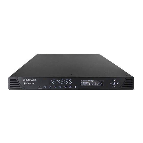
Safran SecureSync 2400 User Manual
Hide thumbs
Also See for SecureSync 2400:
- Getting started manual (39 pages) ,
- Getting started manual (40 pages)

Related Manuals for Safran SecureSync 2400


Summary of Contents for Safran SecureSync 2400
- Page 1 ELECTRONICS & DEFENSE SecureSync 2400 MODEL User Manual Document Part No.: 2400-5000-0050 Revision: 5.2 Date: 22-August-2023...
- Page 3 Safran for its use, nor for any infringements of patents or other rights of third parties that may result from its use. Safran reserves the right to make changes without further notice to any products herein. Safran makes no warranty,...
- Page 4 Blank page. SecureSync 2400 User Manual...
-
Page 5: Table Of Contents
1.6.3.1 10 MHz Output — Oscillator Phase Noise (dBc/Hz) 1.6.4 Multi I/O 1.6.5 DCLS Output 1.6.5.1 1PPS Output 1.6.6 10/100/1000 Ethernet Port (RJ45) 1.6.7 10/100/1000 Ethernet Port (SFP) 1.6.8 RS-232 Serial Port (Rear Panel) 1.6.9 USB Serial Port (Front Panel) • TABLE OF CONTENTS SecureSync 2400 User Manual... - Page 6 2.9.3.1 Hot Swap Installation 2.9.3.2 Hot Swap Monitoring 2.10 Powering Up the Unit 2.11 Zero Configuration Setup 2.11.1 Using Zeroconf 2.12 Setting up an IP Address 2.12.1 Dynamic vs. Static IP Address • TABLE OF CONTENTS SecureSync 2400 User Manual...
- Page 7 2.14.10 System Time Message 2.14.10.1 System Time Message Format 2.15 Configure NTP 2.15.1 Checklist NTP Configuration 2.15.2 The NTP Setup Screen 2.15.3 Dis-/Enabling NTP 2.15.4 Viewing NTP Clients 2.15.5 Restoring the Default NTP Configuration • TABLE OF CONTENTS SecureSync 2400 User Manual...
- Page 8 2.15.12.5 Configuring Anycast via NTP Expert Mode 2.15.12.6 Testing NTP over Anycast 2.15.13 NTP Orphan Mode 2.15.14 Host Disciplining 2.15.15 NTP Expert Mode 2.15.16 Safran Technical Support for NTP 2.16 Configuring PTP 2.16.1 The PTP Screen 2.16.1.1 The PTP Settings Panel 2.16.1.2 The PTP Statistics Panel 2.16.2 Enabling/Disabling PTP...
- Page 9 3.2.2.1 Configuring a Timescale Offset 3.2.3 Leap Seconds 3.2.3.1 Reasons for a Leap Second Correction 3.2.3.2 Leap Second Alert Notification 3.2.3.3 Leap Second Correction Sequence 3.2.3.4 Configuring a Leap Second 3.2.4 Local Clock(s), DST • TABLE OF CONTENTS SecureSync 2400 User Manual...
- Page 10 3.5.3 Monitoring the Oscillator 3.5.4 Oscillator Logs CHAPTER 4 System Administration 4.1 Powering Up/Shutting Down 4.1.1 Powering Up the Unit 4.1.2 Shutting Down the Unit 4.1.3 Issuing the HALT Command Before Removing Power • TABLE OF CONTENTS VIII SecureSync 2400 User Manual...
- Page 11 4.4.1 REST API Configuration 4.4.2 Configuring the Front Panel 4.4.2.1 To change the time display on the front panel: 4.4.2.2 To lock or unlock the front panel: 4.4.3 Creating a Login Banner • TABLE OF CONTENTS SecureSync 2400 User Manual...
- Page 12 4.7.5 Restoring the Factory Defaults 4.7.6 Resetting the Unit to Factory Configuration 4.7.6.1 Resetting All Configurations to their Factory Defaults 4.7.7 Default and Recommended Configurations 4.7.8 Sanitizing the Unit 4.7.8.1 Sanitizing Process 4.7.8.2 Further Reading • TABLE OF CONTENTS SecureSync 2400 User Manual...
- Page 13 5.2.2.11 [8]: Frequency Output Cards: Wiring 5.2.2.12 [9]: Alarm Relay Card, Cable Installation 5.2.2.13 [10]: NENA-Compliant Card, Cable Installation 5.2.2.14 [11]: Verifying HW Detection and SW Update 5.2.2.15 [12]: Restoring Reference Priority Configuration • TABLE OF CONTENTS SecureSync 2400 User Manual...
- Page 14 5.4 Time Code Data Formats 5.4.1 NMEA GGA Message 5.4.2 NMEA RMC Message 5.4.3 NMEA ZDA Message 5.4.4 Spectracom Format 0 5.4.5 Spectracom Format 1 5.4.6 Spectracom Format 1S 5.4.7 Spectracom Format 2 • TABLE OF CONTENTS SecureSync 2400 User Manual...
- Page 15 5.5.4 IRIG E Output 5.5.5 IRIG Output Accuracy Specifications 5.6 Technical Support 5.6.1 Regional Contact 5.7 Return Shipments 5.8 List of Tables 5.9 List of Images 5.10 Document Revision History INDEX • TABLE OF CONTENTS SecureSync 2400 User Manual XIII...
- Page 16 BLANK PAGE. • TABLE OF CONTENTS SecureSync 2400 User Manual...
-
Page 17: Product Description
CHAPTER 1 Product Description The Chapter presents an overview of the SecureSync 2400 Time and Fre- quency Synchronization System, its capabilities, main technical features and specifications. The following topics are included in this Chapter: 1.1 Getting Started 1.2 SecureSync Introduction 1.3 SecureSync Front Panel... -
Page 18: Getting Started
IEC60320 connector. DC power as back-up to AC power, or as the primary input power source, is also available, and power selections can involve either fixed or Hot Swap configurations. SecureSync combines Safran’s precision master clock technology and secure net- work-centric approach with a compact modular hardware design to bring you a CHAPTER •... -
Page 19: Securesync's Inputs And Outputs
This enables SecureSync- equipped computer networks to synchronize anywhere on the planet. SecureSync Front Panel The front panel of a SecureSync unit consists of: CHAPTER • SecureSync 2400 User Manual Rev. 5.2... -
Page 20: Status Leds
Figure 1-1: SecureSync front panel layout 1.3.1 Status LEDs SecureSync's front panel status LEDs provide a real-time status overview: Seven (7) LEDs indicate the unit's current operating state. Figure 1-2: Front panel LEDs CHAPTER • SecureSync 2400 User Manual Rev. 5.2... -
Page 21: Blinking Intervals
No power Powered No GNSS reception (0 satellites) HEARTBEAT GNSS acquisition in process (≥1 satellite(s), or 1PPS OK, or Time OK FAST Antenna short circuit GNSS is available as reference (1PPS and Time OK) CHAPTER • SecureSync 2400 User Manual Rev. 5.2... -
Page 22: Front Panel Keypad, And Display
The front panel keypad, information display menu, and status LED menu buttons can be used to configure basic network settings and obtain status information. For more complex functionality, users should refer to the Web UI or Command Line Interface (CLI). CHAPTER • SecureSync 2400 User Manual Rev. 5.2... -
Page 23: Using The Keypad
2. Press a menu button to enter that menu on the front panel display. 3. After entering a menu, the cursor will automatically begin on the submenu selection that you last visited. 4. Use the left and right buttons to switch between submenus if necessary. CHAPTER • SecureSync 2400 User Manual Rev. 5.2... - Page 24 Front Panel Display: Menu Tree The illustration below shows how the menu is organized, and which functions can be accessed via the front panel (i.e. without using the Web UI): Figure 1-4: Front panel menu tree CHAPTER • SecureSync 2400 User Manual Rev. 5.2...
- Page 25 Hot Swap this sub menu will only be available if you have a Hot Swap Power Supply configuration. See "Hot Swap Power Supply" on page 56 more information. CHAPTER • SecureSync 2400 User Manual Rev. 5.2...
- Page 26 Monitoring view the following information: antenna status PPS validity time validity state view for each satellite system: chart of all visible satellites Inputs Menu: Settings CHAPTER • SecureSync 2400 User Manual Rev. 5.2...
- Page 27 Time Menu: Settings: change the current time display Monitoring: view the oscillator type, disciplining state, and TFOM value Date: view the Day Month Year. Outputs Menu: Settings CHAPTER • SecureSync 2400 User Manual Rev. 5.2...
- Page 28 Monitoring: View a graph for each ETH connection (highlight eth0 or eth1 and toggle left and right) Alerts Menu: Status show current major or minor alarms and descriptions Monitoring monitor memory usage monitor CPU usage monitor disk usage Test CHAPTER • SecureSync 2400 User Manual Rev. 5.2...
-
Page 29: Unit Rear Panel
DCLS Output (BNC female connector) ETH0 1GB Ethernet (RJ45 connector) ETH1 Ethernet (SFP connector) Serial console (RJ45 connector) Two or six slots for option cards AC power input connection Figure 1-5: Standard rear panel CHAPTER • SecureSync 2400 User Manual Rev. 5.2... - Page 30 (for technically proficient service personnel only). Your local Sales Office will gladly assist you with the optimal option cards selection for your application. CHAPTER • SecureSync 2400 User Manual Rev. 5.2...
-
Page 31: Option Cards
ALWAYS from the top. It is therefore necessary to remove the top cover of the main chassis (housing). Input and outputs can be categorized by: Communication direction: Input Output Signal type: Frequency: 1/5/10/[programmable] MHz Wave form (square, sinus) CHAPTER • SecureSync 2400 User Manual Rev. 5.2... - Page 32 "Option Card Identification" on page 20. To locate option card topics in this manual by their heading or functionality, see "Option Cards" on page 361. This Chapter also includes information on field installation and Web UI functionality. CHAPTER • SecureSync 2400 User Manual Rev. 5.2...
-
Page 33: Option Cards Overview
* Every option card has a unique 2-digit ID number located on its cover plate, and in the center column of the table below. The com- plete Safran Part Number for option cards is 1204-xx (e.g., 1204-18). Table 1-4: Option cards identification Function... - Page 34 8 MHz (1x) block, unbal. E1/T1 10-pin (2x) E1/T1 data, E1/T1 Out BNC unbal. E1/T1 75 Ω (4x) (4x) E1/T1 data, E1/T1 Out Ter- unbal. E1/T1 Terminal 100/120 Ω minal (4x) block, 10-pin Time Code Cards CHAPTER • SecureSync 2400 User Manual Rev. 5.2...
- Page 35 HAVE HAVE QUICK Terminal QUICK out Out, RS-485 block, RS-485 10-pin HAVE HAVE QUICK QUICK (4x) Networking Cards 1Gb PTP: Gb PTP 1PPS (1x Master BNC), SFP (1x), SFP only (1x) (1x) CHAPTER • SecureSync 2400 User Manual Rev. 5.2...
-
Page 36: Option Card Identification
The ID number is comprised of the two center digits of your option card's Safran Part Number: 1204-0180-0600. CHAPTER • SecureSync 2400 User Manual Rev. 5.2... - Page 37 Output module (Sine Sine page 406 Wave) "Simulcast (CTCSS/Data CTCSS, Data Sync/Clock Simulcast Clock) [1204-14]" on page 415 module ("Simulcast") "IRIG Out [1204-15, -1E, -22]" IRIG module, BNC (4 out- IRIG Out BNC on page 432 puts) CHAPTER • SecureSync 2400 User Manual Rev. 5.2...
- Page 38 (Fiber Optic) "1PPS Out [1204-18, -19, -21, - Quad 1 PPS output module 1PPS Out, Fiber 2B]" on page 386 (Fiber Optic) "Revertive Selector Card Revertive Selector module [1204-2E]" on page 543 ("Failover") CHAPTER • SecureSync 2400 User Manual Rev. 5.2...
-
Page 39: Option Card Connectors
IRIG, HAVE DCLS QUICK, ST Fiber Optic AM sine wave, DCLS IRIG, 1PPS Terminal Block RS-485 1PPS, frequency, [ Recommended ASCII time code, mating connector: IRIG, Phoenix Contact, HAVEQUICK, part no. 182 7787] Alarm, T1/E1 CHAPTER • SecureSync 2400 User Manual Rev. 5.2... -
Page 40: Specifications
1.6.1 Input Power AC power source: 100 to 240 V , ±10 %, 50/60 Hz DC power source (option): 12-17 V -15%, +20%, or 21-60 V -15%, +20%, secure locking device CHAPTER • SecureSync 2400 User Manual Rev. 5.2... -
Page 41: Gnss Receiver
Antenna connector: SMA (SMA to N-type conversion cable included in anxillary kit) 1.6.3 10 MHz Output Signal: 10 MHz sine wave Level: +13 dBm ±2dB into 50 Ω Signal Harmonics: ˗40 dBc minimum CHAPTER • SecureSync 2400 User Manual Rev. 5.2... - Page 42 (without GPS after 2 Stability (p˗p) weeks of GPS lock) 1 sec. 10 sec. sec. Low-phase noise 5x10 /month (3x10 1x10 1x10 5x10 1x10 Rubidium /month typical) Rubidium 5x10 /month (3x10 1x10 9x10 4x10 1x10 /month typical) CHAPTER • SecureSync 2400 User Manual Rev. 5.2...
-
Page 43: 10 Mhz Output - Oscillator Phase Noise (Dbc/Hz)
Input level 1.5 V (min), impedance 50 Ω DCLS OUT: Output level 5 V (peak), impedance 50 Ω IRIG AM OUT: Output impedance - 50 Ω Output level: 10 V (peak to peak max, user configurable) CHAPTER • SecureSync 2400 User Manual Rev. 5.2... - Page 44 Multi I/O connector, viewed in mating direction on rear of unit Table 1-9: Multi I/O connector signal pinout Signal DCLS IN (First signal) RS485 A, non-inverting (Second signal) RS485 A, non-inverting RS232 TX OUT CHAPTER • SecureSync 2400 User Manual Rev. 5.2...
-
Page 45: Dcls Output
HaveQuick Output, and GPIO Output. For more information, see "Configurable Connectors" on page 157. 1.6.5.1 1PPS Output Signal: One pulse-per-second square wave (ext. reference connected to GNSS receiver) Signal level: TTL compatible, 4.3 V minimum, base-to-peak into 50 Ω CHAPTER • SecureSync 2400 User Manual Rev. 5.2... -
Page 46: 10/100/1000 Ethernet Port (Rj45)
Function: 10/100/1000 (speed depends on connection) Base- T, auto- sensing LAN connection for NTP/SNTP and remote management and configuration, mon- itoring, diagnostics and upgrade Connector: Ethernet via SFP Bel SFP-1GBT-05 (available from Safran as SFP-COPPER) Bel SFP-1GBT-06 GBIC 1000BASE-T 6COM 6C-SFP-T Avago ABCU-5740RZ CHAPTER •... -
Page 47: Serial Port (Rear Panel)
1.6 Specifications Avago ABCU-5741ARZ Finisar FCLF8522P2BTL Proline SFP-TX-CDW Avago AFBR-5710LZ (available from Safran as SFP-FIBER-MM) Finisar FTLF1318P3BTL (available from Safran as SFP-FIBER-SM) An SFP module found to NOT be supported: Arista SFP-1G-T 1.6.8 RS-232 Serial Port (Rear Panel) Function: Accepts commands to locally configure the IP network parameters via CLI for initial unit configuration. -
Page 48: Protocols Supported
Designed for EIA 19” rack mount: Housing w/o connectors and brackets: 17.1” W x 1.74” H [1U] x 15.17” D actual (434 mm W x 44 mm H x 385 mm D) CHAPTER • SecureSync 2400 User Manual Rev. 5.2... - Page 49 45000 ft (13716 m) Shock and Vibration (Operating and Storage): Shock: 516.8 15g, 11 ms halfsine Vibration: 514.8C-2 cat 4 and 514.8D-11, cat 21 1.1 g rms vertical and 0.8 g rms longitudinal CHAPTER • SecureSync 2400 User Manual Rev. 5.2...
-
Page 50: The Securesync Web Ui
The HOME screen can be accessed from anywhere in the Web UI, using the HOME button in the Primary Navigation Bar: The Primary Navigation Bar provides access to all menus: CHAPTER • SecureSync 2400 User Manual Rev. 5.2... -
Page 51: The Interfaces Menu
TOOLS: Opens a drop-down menu for access to the system maintenance screens and system logs. HELP: Provides Safran Service Contact Information and high-level system configurations you may be required to furnish when contacting Safran Ser- vice. 1.7.2 The INTERFACES Menu The INTERFACES menu on the Main screen provides access to SecureSync's: External REFERENCES e.g., the GNSS reference input... -
Page 52: The Configuration Management Menu
Trap and/or email. Time Management: Manage the Local Clock, UTC Offset, DST Definition and Leap Second information. Configuration: Manage the system logs. Disciplining: Manage oscillator disciplining. Change My Password: Configure the admin password. CHAPTER • SecureSync 2400 User Manual Rev. 5.2... -
Page 53: The Tools Menu
Operation of this equipment in a residential area is likely to cause harmful inter- ference in which case the user will be required to correct the interference at his/her own expense. CHAPTER • SecureSync 2400 User Manual Rev. 5.2... - Page 54 EN 303 413 V1.1.1 European Directives This product has been tested and complies with the following: 2014/30/EU Electromagnetic Compatibility (EMC) 2014/35 EU Low Voltage (LVD) 2011/65/EU with Amendment 2015/863/EU on the Restriction of Haz- CHAPTER • SecureSync 2400 User Manual Rev. 5.2...
- Page 55 1.8 Regulatory Compliance ardous Substance (RoHS3) 2014/53/EU Radio Equipment Directive (RED) Environmental Compliance WEEE (Waste Electrical and Electronic Equipment) REACH (Registration, Evaluation, Authorization and Restriction of Chem- icals) CHAPTER • SecureSync 2400 User Manual Rev. 5.2...
- Page 56 1.8 Regulatory Compliance BLANK PAGE. CHAPTER • SecureSync 2400 User Manual Rev. 5.2...
-
Page 57: Setup
2.13 Accessing the Web UI 2.14 Configure Network Settings 2.15 Configure NTP 2.16 Configuring PTP 2.17 GPSD Setup 2.18 Configurable Connectors 2.19 Configuring Input References 2.20 Configuring Outputs 2.21 The Option Cards Screen 2.22 Signature Control CHAPTER • SecureSync 2400 User Manual... -
Page 58: Installation Overview
2. Unpack the unit, and take inventory: "Unpacking and Inventory" on the facing page. 3. Obtain required tools and parts: "Required Tools and Parts" on page 44. 4. Mount the unit: ."Mounting the Unit" on page 48. CHAPTER • SecureSync 2400 User Manual Rev. 5.2... -
Page 59: Unpacking And Inventory
(ESD). Observe ESD precautions and safeguards when handling the unit. Unpack the equipment and inspect it for damage. If any equipment has been damaged in transit, or you experience any problems during installation and con- figuration of your Safran product, please contact Safran (see "Technical Support" page 605). Note: Retain original packaging for use in return shipments if neces- sary. -
Page 60: Required Tools And Parts
GNSS antenna with mounting bracket GNSS antenna surge suppressor (recommended) GNSS antenna inline amplifier (optional for short cable lengths) For antenna installation guidelines, see the separate documentation shipped with the antenna components. CHAPTER • SecureSync 2400 User Manual Rev. 5.2... -
Page 61: Safety
CHAPTER • SecureSync 2400 User Manual Rev. 5.2... - Page 62 — DO NOT OPEN EQUIPMENT, UNLESS AUTHORIZED: The interior of this equipment does not have any user-serviceable parts. Contact Safran Technical Support if this equipment needs to be serviced. Do not open the equipment, unless instructed to do so by Safran Service personnel. Follow Safran Safety instructions and observe all local electrical regulatory requirements.
- Page 63 Do not modify the equipment. Use only spare parts authorized by Safran. Always follow the instructions set out in this User Manual, or in other Safran documentation for this product. Observe generally applicable legal and other local mandatory regulations.
-
Page 64: Mounting The Unit
Reliable grounding of rack-mounted equipment must be maintained. Par- ticular attention must be given to supply connections other than direct con- nections to the branch circuit (e.g., use of power strips). CHAPTER • SecureSync 2400 User Manual Rev. 5.2... -
Page 65: Rack Mounting (Ears)
SecureSync front panel. (See image below). To secure, use the #2 Phillips screwdriver, and 3 each of the HM20R- 04R7- 0010 M4 flat head Phillips screws per side. Figure 2-1: Rack mount installation CHAPTER • SecureSync 2400 User Manual Rev. 5.2... -
Page 66: Connecting The Gnss Input
The SMA-to-N-type conversion cable included in the ancillary kit is approved for pull weight of up to 60 lbs. If you are using a heavier cable, you will need to apply appropriate strain relief. CHAPTER • SecureSync 2400 User Manual Rev. 5.2... -
Page 67: Connecting Network Cables
2.7 Connecting Network Cables For additional information on GNSS antenna installation considerations, including cabling, a Safran tech note is available here. 2. Connect the GNSS cable to the rear panel antenna input jack. Initial synchronization with GNSS input may take up to 12 minutes (approx- imately) when used in the default stationary GNSS operating mode. -
Page 68: Connecting Inputs And Outputs
Note that some option cards offer both input and output functionality, while oth- ers offer only one or the other. Connecting Supply Power Depending on the equipment configuration at time of purchase, SecureSync may be powered from different sources. CHAPTER • SecureSync 2400 User Manual Rev. 5.2... -
Page 69: Using Ac Input Power
2.9 Connecting Supply Power Table 2-2: SecureSync 2400 Power Supply via Part Number Part number Connections Power Supply 240x- AC (fixed) 240x- 12 V DC (fixed) 240x- 24 V DC (fixed) 240x- 1-2 (Hot Swap) AC, DC (12 V or 24 V), in any combination... - Page 70 SecureSync units can be ordered in a DC version that includes the following DC receptacle on the back panel: DC Receptacle , 2-pin, chassis mount: Amphenol 97-3102A-10SL-4P(946); (Safran P/N J240R-0021-000G) or DC Receptacle , 3- pin, chassis mount: Amphenol 97- 3102A- 10SL- 3P (946) (Safran P/N J240R- 0032-012F): Figure 2-3:...
- Page 71 16AWG,13A,300V: Amphenol P/N DL3106A10SL-3S; (Safran part no. P240R-0032-002F): Figure 2-4: DC Connector, 2-Pin and DC Connector, 3-Pin Cable Clamp, circular: Amphenol P/N: 97-3057-1004(621); (Safran part no. MP06R-0004-0001) Figure 2-5: Cable Clamp, DC Power Pinout description, DC connectors Pin B goes to the most positive DC voltage of the DC source. For +12 V or +24/48 V this would be the positive output from the DC source.
-
Page 72: Hot Swap Power Supply
2.9 Connecting Supply Power A +24/48 V power supply can optionally be used as an AC input: Safran offers a kit containing an AC/DC converter with assembled DC connector: The part number for this adapter kit is PS06R-2Z1M-DT01. Figure 2-6: DC to AC Converter 2.9.3... -
Page 73: Hot Swap Installation
Grey if the monitoring on both sleds has been disabled. In this panel, you can also download (or clear) a file of the most recent mon- itoring information for both bays. CHAPTER • SecureSync 2400 User Manual Rev. 5.2... - Page 74 Okay (provided there is one fully func- tional power supply installed). Power Type: AC 110/220 V, DC 12/24 V, or DC 24/48 V Voltage CHAPTER • SecureSync 2400 User Manual Rev. 5.2...
- Page 75 Bay 2 is with the fan speed and voltage). You can also disable monitoring on a specific bay by pressing the ✓ ENTER key while the bay is highlighted. Bays with disabled monitoring will be noted on the front panel: CHAPTER • SecureSync 2400 User Manual Rev. 5.2...
- Page 76 Temperature AC sled (<-25 °C) or (> 85°C) Temperature DC sled (<-40 °C) or (> 85°C) Unknown Sled Type installed CHAPTER • SecureSync 2400 User Manual Rev. 5.2...
-
Page 77: Powering Up The Unit
LED will be either OFF or flashing HEARTBEAT, since synchronization has not yet been achieved. Alarms LED light should be OFF (startup behavior) or HEARTBEAT (acquiring fix behavior). A FAST blinking pattern would indicate the unit requires attention. CHAPTER • SecureSync 2400 User Manual Rev. 5.2... - Page 78 2.10 Powering Up the Unit For additional information, see "Status LEDs" on page 4 "Status Monitoring via Front Panel" on page 302. CHAPTER • SecureSync 2400 User Manual Rev. 5.2...
-
Page 79: Zero Configuration Setup
Windows 7/8 users should install Bonjour Print Services, otherwise access to *.local addresses will not be possible. Windows 10 already supports mDNS and DNS-SD, hence there is no need to install additional software. CHAPTER • SecureSync 2400 User Manual Rev. 5.2... -
Page 80: Using Zeroconf
Setting up an IP Address In order for SecureSync to be accessible via your network, you need to assign an IP address to SecureSync, as well as a subnet mask and gateway, unless you are CHAPTER • SecureSync 2400 User Manual Rev. 5.2... -
Page 81: Dynamic Vs. Static Ip Address
If you plan on allowing your SecureSync to use this negotiated DHCP Address on a permanent basis, you can skip the following topics about setting up an IP CHAPTER • SecureSync 2400 User Manual Rev. 5.2... -
Page 82: Assigning A Static Ip Address
DHCP server assign a new IP address to SecureSync. 2.12.2 Assigning a Static IP Address Safran recommends assigning a static IP address to SecureSync, even if the unit is connected to a DHCP server. This can be accomplished in several ways: a. Via the... - Page 83 Button. Ensure that you are on the Set- tings submenu. 2. Using the arrow key, press down once and press L/R to select the Eth- ernet interface for which DHCP is to be disabled, such as eth0. CHAPTER • SecureSync 2400 User Manual Rev. 5.2...
- Page 84 The remainder of the configuration settings can be performed via the Web UI ® (accessed via an external workstation with a web browser such as Firefox ® Chrome ). For more information, see "The Web UI HOME Screen" on page 34. CHAPTER • SecureSync 2400 User Manual Rev. 5.2...
-
Page 85: Setting Up A Static Ip Address Via A Dhcp Network
The serial ports can be used to make configuration changes (such as the network settings), retrieve operational data (e.g., GNSS receiver information) and log files, or to perform operations such as resetting the admin password. CHAPTER • SecureSync 2400 User Manual Rev. 5.2... -
Page 86: Setting Up A Static Ip Address Via Ethernet Cable
Setting up a Static IP Address via Ethernet Cable This procedure will allow you to configure SecureSync using the Web UI directly via the Ethernet port, if you cannot or do not wish to use a DHCP network. CHAPTER • SecureSync 2400 User Manual Rev. 5.2... -
Page 87: Subnet Mask Values
You can access the Web UI either by using the automatically assigned DHCP IP address, or by using a manually set static IP address (see "Assigning a Static IP Address" on page 66): CHAPTER • SecureSync 2400 User Manual Rev. 5.2... - Page 88 "HTTPS" on page 81 for more information on creating a new SSL certificate. 3. Log into the Web UI as an administrator. The factory-default administrator user name and password are: Username: spadmin Password: admin123 CHAPTER • SecureSync 2400 User Manual Rev. 5.2...
-
Page 89: Configure Network Settings
"Managing Passwords" on page 278. 4. Upon initial login, you will be asked to register your product. Safran recom- mends to register SecureSync, so as to receive software updates and ser- vices notices. See also "Product Registration" on page 301. - Page 90 For details, see "System Time Mes- sage" on page 111. VLAN: This button will reveal the VLAN Setup popup window. For more information, see "VLAN Support" on page 111. CHAPTER • SecureSync 2400 User Manual Rev. 5.2...
-
Page 91: General Network Settings
Hostname: This is the server’s identity on the network or IP address. Default IPv4 Port: Unless you specify a specific Port to be used as Default Port, the factory default port eth0 will be used as the gate- way (default gateway). CHAPTER • SecureSync 2400 User Manual Rev. 5.2... -
Page 92: Network Ports
The default subnet is: 255.255.0.0 Netmask: This is the network subnet mask assigned by the network administrator. In the form “xxx.xxx.xxx.xxx.” See "Subnet Mask Val- ues" on page 71 for a list of subnet mask values. CHAPTER • SecureSync 2400 User Manual Rev. 5.2... -
Page 93: Network Services
The Network Services panel has ON/OFF toggle switches for the following dae- mons and features: System Time Message: A once-per second Time Message sent out via Mult- icast; for details, see "System Time Message" on page 111. CHAPTER • SecureSync 2400 User Manual Rev. 5.2... -
Page 94: Static Routes
DHCP (Dynamic Host Con- figuration Protocol). With statically configured networks, static routes are in fact the only possible way to route network traffic. To view, add, edit, or delete a static route: CHAPTER • SecureSync 2400 User Manual Rev. 5.2... - Page 95 To set up a static route, the Ethernet connector must be physically connected to the network. Note: Do not use the same route for different Ethernet ports; a route that has been used elsewhere will be rejec- ted. CHAPTER • SecureSync 2400 User Manual Rev. 5.2...
-
Page 96: Access Rules
10.10.0.0/16 , where 10.10.0.0 is the IP address and is the sub- "Subnet Mask Values" on page 71 net mask in prefix form. See the table for a list of subnet mask values. CHAPTER • SecureSync 2400 User Manual Rev. 5.2... -
Page 97: Https
"HTTPS Security Levels" on page 296. 2.14.6.1 Accessing the HTTPS Setup Window 1. Navigate to MANAGEMENT > NETWORK: HTTPS Setup (or, navigate to MANAGEMENT > Network Setup, and click HTTPS in the Actions panel on CHAPTER • SecureSync 2400 User Manual Rev. 5.2... - Page 98 Exiting the HTTPS Setup window will not lose and Subject Alternative Names that have been entered. When switching between tabs within the HTTPS Setup window, the information you have entered will be retained. CHAPTER • SecureSync 2400 User Manual Rev. 5.2...
-
Page 99: 2.14.6.2 About Https
If a Certificate Authority is not available, or while you are waiting for the cer- tificate to be issued, you can use the default Safran self-signed SSL certificate that comes with the unit until it expires, or use your own self-signed certificate. -
Page 100: 2.14.6.4 Supported Certificate Formats
"Adding HTTPS Subject Alternative Names" on page 87. To create an HTTPS Certificate Request: 1. Navigate to MANAGEMENT > NETWORK: HTTPS Setup, or in the MANAGEMENT > NETWORK Setup, Actions panel, select HTTPS: CHAPTER • SecureSync 2400 User Manual Rev. 5.2... - Page 101 Certificate. Caution: Once you click Submit, a previously generated Cer- tificate (or the Safran default Certificate) will be overwritten. Note that an invalid Certificate may result in denial of access to SecureSync via the Web UI! 4.
- Page 102 The remaining fields are optional. It is recommended that you consult your Certificate Authority for the required fields in an X 509-Certificate request. Safran recommends all fields be filled out and match the information given to your Certificate Authority.
-
Page 103: 2.14.6.6 Adding Https Subject Alternative Names
Subject Alternative Names. Any information entered into the Create Certificate Request tab that has not been submitted will be lost by adding, deleting, or editing Subject Alternative Names. CHAPTER • SecureSync 2400 User Manual Rev. 5.2... - Page 104 IP address, or URL used to reach the host via HTTPS. 4. After completing and submitting the form, view the Subject Alternative Name tab to see existing entries. Existing Subject Alternative Names can be edited or deleted from this window. CHAPTER • SecureSync 2400 User Manual Rev. 5.2...
-
Page 105: 2.14.6.7 Requesting An Https Certificate
6. OPTIONAL: While waiting for the certificate to be issued by the Certificate Authority, you may use the certificate from the Certificate Request window as a self-signed certificate (see below). NOTE: Preventing accidental overwriting of an existing certificate: CHAPTER • SecureSync 2400 User Manual Rev. 5.2... -
Page 106: 2.14.6.8 Uploading An X.509 Pem Certificate Text
It is also possible to upload a X.509 PEM Certificate Chain by pasting the text of the second certificate behind the regular CA Certificate. Uploading X.509 PEM certificate text To upload an X.509 PEM Certificate text to SecureSync: CHAPTER • SecureSync 2400 User Manual Rev. 5.2... -
Page 107: 2.14.6.9 Uploading An Https Certificate File
1. Store the Public Keys File provided to you by the Certificate Authority in a location accessible from the computer on which you are running the Web UI. 2. In the Web UI, navigate to MANAGEMENT > NETWORK: HTTPS Setup. 3. Select the tab Upload Certificate File. CHAPTER • SecureSync 2400 User Manual Rev. 5.2... -
Page 108: Ssh
SSH uses host keys to uniquely identify each SSH server. Host keys are used for server authentication and identification. A secure unit permits users to create or delete RSA or DSA keys for the SSH2 protocol. CHAPTER • SecureSync 2400 User Manual Rev. 5.2... - Page 109 Keys: SSH uses Host Keys to uniquely identify each SSH server. Host keys are used for server authentication and identification. Public Key: This is a text field interface that allows the user to edit the public key files authorized_keys file. CHAPTER • SecureSync 2400 User Manual Rev. 5.2...
- Page 110 SSH allows you to remotely login or transfer files by identifying your account and the target machine's IP address. As a user you can authenticate yourself by using your account password, or by using a Public Private Key Pair. CHAPTER • SecureSync 2400 User Manual Rev. 5.2...
- Page 111 10 minutes or more to generate. DSA keys size support is limited to 1024 bits. The key type ED25519 supports 256 bits. 3. Check the Regenerate All Keys box. 4. Click Submit. The new values will be saved. CHAPTER • SecureSync 2400 User Manual Rev. 5.2...
- Page 112 If the unit is rebooted with host key creation in progress, or the unit is booted and no host keys exist, the key generation process is restarted. The key generation process uses the pre- viously specified key sizes. CHAPTER • SecureSync 2400 User Manual Rev. 5.2...
- Page 113 MANAGEMENT > NETWORK: SSH Setup. The SSH Setup win- dow will open to the Host Keys tab by default. 2. Select the Public Key tab. The authorized_keys file appears in the Public Keys File window: CHAPTER • SecureSync 2400 User Manual Rev. 5.2...
- Page 114 Creating an SSH session with Password Authentication for the admin account ssh spadmin@10.10.200.5 spadmin@10.10.200.5's password: admin123 You are now presented with boot up text and/or a “>” prompt which allows the use of the Safran command line interface. CHAPTER • SecureSync 2400 User Manual Rev. 5.2...
- Page 115 Creating an SSH session using Public Key with Passphrase Authentic- ation for the admin account You must first provide the secure Safran product a RSA public key found typ- ically in the OpenSSH id_rsa.pub file. Then you may attempt to create an SSH ses- sion.
-
Page 116: Snmp
You will be presented with the SFTP prompt allowing interactive file transfer and directory navigation. Recommended SSH Client Tools Safran does not make any recommendations for specific SSH clients, SCP clients, or SFTP client tools. However, there are many SSH based tools available to the user at low cost or free. - Page 117 SNMP V1/V2c Settings for Access Screen. See "SNMP V1/V2c" on page 105. SNMP V3: This panel allows configuration of SNMP v3 func- tionality, including the user name, read/write permissions, authorization passwords as well as privilege Types and CHAPTER • SecureSync 2400 User Manual Rev. 5.2...
- Page 118 2. In the Actions panel, click the Restore Default SNMP Configuration but- ton. 3. Confirm that you want to restore the default settings in the pop-up mes- sage. Configuring the SNMP Status CHAPTER • SecureSync 2400 User Manual Rev. 5.2...
- Page 119 4. Click Submit, or cancel by clicking the X-icon in the top-right corner. Accessing the SNMP Support MIB Files Safran Trusted 4D (formerly Orolia/Spectracom)’s private enterprise MIB files can be extracted via File Transfer Protocol (FTP) from SecureSync, using an FTP client such as FileZilla or any other shareware/freeware FTP program.
- Page 120 To obtain the MIB files from SecureSync via FTP/SFTP: 1. Using an FTP program, log in as an administrator. 2. Through the FTP program, locate Safran Trusted 4D's Spectracom MIB files in the /home/spectracom/mibs directory. 3. FTP the files to the desired location on your PC for later transfer to the SNMP Manager.
-
Page 121: Snmp V1/V2C
SNMP Community names should be between 4 and 32 characters in length. Permissions may be Read Only or Read/Write. Version field provides a choice of V1 or V2c. CHAPTER • SecureSync 2400 User Manual Rev. 5.2... -
Page 122: 2.14.8.2 Snmp V3
Submit. OR: To delete the entry, click Delete. 2.14.8.2 SNMP V3 SNMP V3 utilizes a user-based security model which, among other things, offer enhanced security over SNMP V1 and V2. CHAPTER • SecureSync 2400 User Manual Rev. 5.2... - Page 123 8 and 32 characters in length. Permissions field provides a choice between Read/Write and Read Only. 5. Click Submit. The created user will appear in the SNMP V3 panel: CHAPTER • SecureSync 2400 User Manual Rev. 5.2...
-
Page 124: 2.14.8.3 Snmp Traps
SecureSync is either currently in Holdover mode or not currently in Holdover mode. For testing purposes, a command line interface command is provided. This com- mand, testevent, allows one, several, or all of the traps defined in the CHAPTER • SecureSync 2400 User Manual Rev. 5.2... - Page 125 The default port is 162. [v1, v2c, v3] The UDP Port number used by SNMP Traps [default = 162]. [v1, v2c] CHAPTER • SecureSync 2400 User Manual Rev. 5.2...
- Page 126 This allows for SNMP Managers in different geographical areas to receive the same SNMP traps. Note: Safran Trusted 4D has been assigned the enterprise iden- tifier 18837 by the IANA (Internet Assigned Numbers Author- ity). The product MIBs reside under the enterprise identifier @18837.3.
-
Page 127: Vlan Support
ID]. 2.14.10 System Time Message The System Time Message is a feature used for special applications that require a once-per-second time message to be sent out by SecureSync via multicast. CHAPTER • SecureSync 2400 User Manual Rev. 5.2... -
Page 128: 2.14.10.1 System Time Message Format
This message contains the time when the next 1PPS discrete will occur. It is sent once per second prior to the 1PPS discrete. Table 2-4: System Time Message format Word Byte 3 Byte 2 Byte 1 Byte 0 Msg ID Msg Size Seconds nSec CHAPTER • SecureSync 2400 User Manual Rev. 5.2... -
Page 129: Configure Ntp
SecureSync will send an NTP response time packet to the requesting client. Under typical conditions, SecureSync can service several thousand NTP requests per second without MD5 authentication enabled, and at a somewhat lower rate with MD5 authentication enabled. CHAPTER • SecureSync 2400 User Manual Rev. 5.2... -
Page 130: Checklist Ntp Configuration
The NTP Setup Screen NTP Setup screen provides access to all NTP configuration settings. To open the NTP Setup screen, navigate to MANAGEMENT > NTP Setup. The NTP Setup screen is divided into 5 panels: CHAPTER • SecureSync 2400 User Manual Rev. 5.2... - Page 131 The NTP Throughput panel … shows two graphs depicting the rate of NTP traffic from Clients and Server- /Peers. The INFO icon opens a window showing the maximum per second traffic rate from each. CHAPTER • SecureSync 2400 User Manual Rev. 5.2...
- Page 132 See "Restoring the Default NTP Configuration" on page 118. The NTP Services panel … is the second panel on the left-hand side of the NTP screen. It has two switches: CHAPTER • SecureSync 2400 User Manual Rev. 5.2...
-
Page 133: Dis-/Enabling Ntp
"NTP Expert Mode" on page 146. Note: Safran Tech Support does not support the editing of the NTP configuration files in Expert Mode. For additional inform- ation on editing the NTP.conf file, please refer to http://www.ntp.org. Other NTP Services that can be configured via the NTP Services panel by click-... -
Page 134: Viewing Ntp Clients
Stratum 1 operation with no other servers or peers, no broadcasting and no access restrictions. External queries or modifications are not permitted, while generally all IPv4 and IPv6 client connections are allowed. To restore SecureSync to its default NTP configuration: CHAPTER • SecureSync 2400 User Manual Rev. 5.2... -
Page 135: Ntp Output Timescale
IMPORTANT: Make sure you select your desired timescale! Using the wrong timescale will inevitably result in an undesired time error in your NTP clients. To change the system timescale SecureSync will use for its NTP output (and other outputs): CHAPTER • SecureSync 2400 User Manual Rev. 5.2... -
Page 136: Ntp Reference Configuration
(or IRIG, ASCII data input, etc.), and distributes that time over the NTP network. This is called Stratum 1 Operation, because SecureSync will be the Stratum 1 (or primary) server. This is the most common con- figuration. CHAPTER • SecureSync 2400 User Manual Rev. 5.2... -
Page 137: The Ntp Stratum Model
Stratum 1 tab. 4. Check all of the three options: Enable Stratum 1 Operation Checking this option will cause the NTP Service to use the System Time provided by the Timing System input. CHAPTER • SecureSync 2400 User Manual Rev. 5.2... -
Page 138: Configuring "Ntp Stratum Synchronization
Prefer Stratum 1 Uncheck this option to prevent SecureSync's NTP service from “weighing” the Timing System input heavier than input from other NTP servers. Thus, during normal operation, the time provided by the CHAPTER • SecureSync 2400 User Manual Rev. 5.2... -
Page 139: Ntp Servers And Peers
Holdover mode and can continue to be the reference to the net- work. However, if no input reference becomes available before the Holdover period expires, Time Sync will be lost and shortly thereafter, NTP will report to CHAPTER • SecureSync 2400 User Manual Rev. 5.2... -
Page 140: The Ntp Servers And Ntp Peers Panels
Note: Servers will be displayed in the Status view only if they can be resolved. They will, however, always be displayed in the Setup view in order to reconfigure them, if necessary. CHAPTER • SecureSync 2400 User Manual Rev. 5.2... -
Page 141: Ntp Servers: Adding, Configuring, Removing
POLL: The polling interval, i.e. how often SecureSync is polling this NTP ref- erence for its time. DELAY (ms): The measured one-way delay between SecureSync and its selected reference. 2.15.8.2 NTP Servers: Adding, Configuring, Removing To add, configure, or remove an NTP Server: CHAPTER • SecureSync 2400 User Manual Rev. 5.2... - Page 142 ACTION GEAR button, and proceed to the next step. REMOVE a server (and its associated configurations), click the X- button next to it, then confirm by clicking OK. CHAPTER • SecureSync 2400 User Manual Rev. 5.2...
- Page 143 This will occur if the connection was inter- rupted, or upon restart of the NTP daemon. For additional inform- ation, please refer to public NTP configuration documentation. CHAPTER • SecureSync 2400 User Manual Rev. 5.2...
-
Page 144: Ntp Peers: Adding, Configuring, Removing
NTP Peer, click the PLUS icon in the top right corner of NTP Peers panel. REMOVE an NTP Peer (and its associated configurations), click the X-button next to it. 3. The NTP Peers edit window opens: CHAPTER • SecureSync 2400 User Manual Rev. 5.2... - Page 145 Preferred: Check this box to prefer this NTP Peer over other NTP Peers ("NTP Peer Preference"). This will result in SecureSync syn- chronizing more frequently with this Peer. For additional information on NTP Preferences, see "Configuring "NTP Stratum 1" Operation" on page 121. CHAPTER • SecureSync 2400 User Manual Rev. 5.2...
-
Page 146: Ntp Authentication
To create, edit, or delete Symmetric Keys (MD5 Authentication): 1. Navigate to MANAGEMENT > NETWORK: NTP Setup. 2. In the Actions panel, click the Symmetric Keys button: 3. The NTP Symmetric Keys window will display: CHAPTER • SecureSync 2400 User Manual Rev. 5.2... - Page 147 MD5 pairs, and the key must be trusted. ID—The key ID must be a number between 1 and 65532. Digest Scheme—Choose one of the options from the drop-down list. The available options are: CHAPTER • SecureSync 2400 User Manual Rev. 5.2...
- Page 148 Submit button. 6. The key(s) you have set up will now appear as options in the Symmetric field in both the NTP Server screen, and the NTP Peer screen. CHAPTER • SecureSync 2400 User Manual Rev. 5.2...
-
Page 149: 2.15.10 Ntp Access Restrictions
To configure NTP Access Restrictions: 1. Navigate to MANAGEMENT > NETWORK: NTP Setup. 2. In the Actions panel, click Access Restrictions: CHAPTER • SecureSync 2400 User Manual Rev. 5.2... - Page 150 SecureSync, but the rest of the network will not have access to SecureSync. By default, SecureSync allows all IPv4 and IPv6 connections. Version—Choose IPv4 or IPv6 Address—Enter the appropriate hostname. Subnet Mask—Enter the appropriate IP mask. CHAPTER • SecureSync 2400 User Manual Rev. 5.2...
-
Page 151: Enabling/Disabling Ntp Broadcasting
Edit NTP Services window will display. Check the Broadcast box. 4. Select a Broadcast Interval. When NTP Broadcasting is selected, in addi- tion to still responding to NTP time requests sent from network appliances, CHAPTER • SecureSync 2400 User Manual Rev. 5.2... -
Page 152: Ntp Over Anycast
As soon as the first SecureSync server obtains a valid reference again, it will make itself available to the OSPF router, which will then use it as a time source again, based on the principle of shortest path available. CHAPTER • SecureSync 2400 User Manual Rev. 5.2... -
Page 153: Configuring Ntp Over Anycast (General Settings)
ETH0 available). If you desire IPv6 functionality, you must also select the IPv6 port address since there may be multiple IPv6 addresses on a single port. 8. Click Submit. CHAPTER • SecureSync 2400 User Manual Rev. 5.2... -
Page 154: Configuring Ntp Over Anycast (Ospf Ipv4)
Anycast server pool, i.e. declare itself an invalid reference. (For more information about TFOM, see "Configuring the Oscillator" on page 252.) CHAPTER • SecureSync 2400 User Manual Rev. 5.2... -
Page 155: Configuring Ntp Over Anycast (Ospf Ipv6)
"tolerance window": A small window will cause SecureSync to deliver a more accurate time window, but also will cause it to quickly with- draw from the Anycast server pool, i.e. declare itself an invalid reference. CHAPTER • SecureSync 2400 User Manual Rev. 5.2... -
Page 156: Configuring Ntp Over Anycast (Bgp)
13. Select the port address to associate the Anycast service with (because there may be multiple addresses on a single port), and click Submit. If no addresses appear, an IP address must be added to the port. CHAPTER • SecureSync 2400 User Manual Rev. 5.2... -
Page 157: 2.15.12.5 Configuring Anycast Via Ntp Expert Mode
Any configurations made in Expert Mode will be lost as soon as Expert Mode is disabled. 1. To access Expert Mode, navigate to MANAGEMENT > NTP Setup. 2. Enable the switch for Expert Mode in the panel Services. CHAPTER • SecureSync 2400 User Manual Rev. 5.2... - Page 158 (Interface eth0 line, followed by only IPv4 line, because no IPv6 address is con- figured on that port. Interface eth1 line, followed by only IPv6 line, because no IPv4 address is configured on that port) ***************************************************** CHAPTER • SecureSync 2400 User Manual Rev. 5.2...
- Page 159 ***************************************************** Example file: ospfd.conf *****************************************************! router ospf ospf router-id 10.2.100.157 network 10.2.0.0/16 area 0.0.0.0 redistribute connected distribute-list default out connected access-list default permit 10.10.14.1/32 access-list default deny any ***************************************************** CHAPTER • SecureSync 2400 User Manual Rev. 5.2...
-
Page 160: 2.15.12.6 Testing Ntp Over Anycast
172.17.0.0/16 neighbor 172.17.1.1 remote-as 3 redistribute connected ***************************************************** 2.15.12.6 Testing NTP over Anycast Note: A detailed Anycast test procedure is available from Safran upon request. Please contact TimingSupport@nav- timing.safrangroup.com. 2.15.13 NTP Orphan Mode The NTP Orphan Mode allows SecureSync to remain a valid time server to its NTP clients even if all its input references have become invalid and the Holdover period has expired. -
Page 161: Host Disciplining
Host Disciplining allows an NTP input reference to discipline SecureSync's oscil- lator. This may be utilized e.g., with SecureSync units that do not have a GPS receiver because they are operated as Stratum 2 servers. CHAPTER • SecureSync 2400 User Manual Rev. 5.2... -
Page 162: Ntp Expert Mode
Mode is enabled, the user has direct access to the NTP.conf file. Caution: Safran Tech Support does not support the editing of the NTP configuration files while in the Expert Mode. For additional information on editing the NTP.conf file, please refer to http://www.ntp.org/. - Page 163 /dev/urandom driftfile /etc/ntp/ntp.drift logfile /home/spectracom/log/ntp.log statsdir /home/spectracom/log/ntpstats/ statistics loopstats peerstats clockstats filegen loopstats file loopstats type day enable filegen peerstats file peerstats type day enable filegen clockstats file clockstats type day enable CHAPTER • SecureSync 2400 User Manual Rev. 5.2...
- Page 164 SecureSync will now use the new NTP con- figuration per the manually edited file. Caution: Any configurations made in NTP Expert Mode will be lost as soon as NTP Expert Mode is disabled. CHAPTER • SecureSync 2400 User Manual Rev. 5.2...
-
Page 165: Safran Technical Support For Ntp
2.16 Configuring PTP 2.15.16 Safran Technical Support for NTP Safran does not provide technical assistance for configuring and installing NTP on Unix-based applications. Please refer to www.ntp.org for NTP information and FAQs. Another helpful source Internet newsgroup news://comp.protocols.time.ntp. ® Safran can provide support for Microsoft... -
Page 166: The Ptp Screen
Each tab allows you to Restore defaults. Note: The PTP settings fields visible will changed based on profile selection and other choices made in the configuration process. CHAPTER • SecureSync 2400 User Manual Rev. 5.2... - Page 167 Peer MAC Address and Alt Timescale Display Name fields.Domain is set to 254. Protocol tab The displayed defaults and available fields visible in this tab will change in response to your Profile, Delay Mechanism, Mode, and Communication Mode selections. CHAPTER • SecureSync 2400 User Manual Rev. 5.2...
- Page 168 Rate: [see Sync Rate above] The rate at which Announce mes- sages are sent, in packets per second. Delay Req Rate: (Request-Response Delay Mechanism Only). Interval between request messages sent by the slave to the master. CHAPTER • SecureSync 2400 User Manual Rev. 5.2...
-
Page 169: The Ptp Statistics Panel
2.16.1.2 The PTP Statistics Panel This panel provides statistics for each Ethernet port. If the PTP is set to OFF for a specific port, this screen will not display any information. CHAPTER • SecureSync 2400 User Manual Rev. 5.2... -
Page 170: Enabling/Disabling Ptp
Count: Message count Average Rate:[e.g., "0.0624986091344933"] Indicates how often the selec- ted message has been detected (in seconds e.g., "1.0" would mean once every second). 2.16.2 Enabling/Disabling PTP To enable or disable PTP: CHAPTER • SecureSync 2400 User Manual Rev. 5.2... -
Page 171: General Configuration Notes
GPSD can only be configured to track the SecureSync internal u-blox receiver. To configure GPSD on the Web UI, navigate to MANAGEMENT > NETWORK > GPSD Setup to access the GPSD Setup Screen CHAPTER • SecureSync 2400 User Manual Rev. 5.2... - Page 172 There are two GPSD utility programs already incorporated into SecureSync; GPSpipe and CGPS. Both can be used as commands within the CLI to view inform- ation currently being sent via GPSD. Both commands use CTL + C to stop. CHAPTER • SecureSync 2400 User Manual Rev. 5.2...
-
Page 173: Configurable Connectors
Note on the table below: Both RS485 connectors have optional termination on their inputs. To select this feature, choose the Web UI feature as listed below that also includes With Termination in the listing. CHAPTER • SecureSync 2400 User Manual Rev. 5.2... - Page 174 PPS_IN | RS485 IRIG Input IRIG_IN | RS485 HaveQuick Input (Default) HQ_IN | RS485 ASCII Time Code Input ATC_IN | RS485 IRIG AM Out- Pin 11 (signal) IRIG AM Output (Default, non-configurable) Pin 12 (ground) CHAPTER • SecureSync 2400 User Manual Rev. 5.2...
- Page 175 DCLS IN (First signal) RS485 A, non-inverting (Second signal) RS485 A, non-inverting RS232 TX OUT DCLS OUT IRIG AM OUT (First signal) RS485 B, inverting (Second signal) RS485 B, inverting RS232 RX IN CHAPTER • SecureSync 2400 User Manual Rev. 5.2...
-
Page 176: Assigning Signals
B. In the Actions panel on the left, click Restore Default Layout. Reloading the Current I/O Configuration To reload the currently used I/O configuration after adding pin layout changes, but before clicking Apply Changes: CHAPTER • SecureSync 2400 User Manual Rev. 5.2... -
Page 177: Network Ports
To access these settings for a given input reference, choose one of the two methods described below. (To disable references or change the priority that your timing system will be guided by those references, visit "Configuring Input Reference Priorities" on page 205). CHAPTER • SecureSync 2400 User Manual Rev. 5.2... -
Page 178: How To Configure An Input Reference
2. In the Status window, click the GEAR button next to the desired input reference. 3. The settings window for the chosen reference will be displayed. Edit the field(s) as desired. For more information, see "Managing References" on page 204. CHAPTER • SecureSync 2400 User Manual Rev. 5.2... -
Page 179: Configure A 1Pps Input
An ASCII Input is available by default configuration through the Multi-I/O con- nector (see "Configurable Connectors" on page 157). To configure the ASCII Input (also referred to as ‘Reference’), go to its Edit win- dow. CHAPTER • SecureSync 2400 User Manual Rev. 5.2... - Page 180 Format fields may appear, allowing you to select one or more time code Formats. For detailed specifications and limitations on the supported time code formats, see "Time Code Data Formats" on page 560. CHAPTER • SecureSync 2400 User Manual Rev. 5.2...
- Page 181 ASCII input correctly could result in time jumps occurring in the System Time when input reference changes occur. These time jumps could affect NTP and normal operation of the sys- tem. CHAPTER • SecureSync 2400 User Manual Rev. 5.2...
-
Page 182: Configure A Havequick Input
Format: Used to configure the formatting of the four available HAVE QUICK outputs. The available output formats are as follows: STANAG 4246 HQ I STANAG 4246 HQ II STANAG 4430 STM STANAG 4430 Ext HQ ICD-GPS-060A BCD ICD-GPS-060A HQ DOD-STD-1399 BCD CHAPTER • SecureSync 2400 User Manual Rev. 5.2... -
Page 183: Configuring An Irig Input
Unless you have an IRIG option card, IRIG AM is not available as an input at this time. To configure the IRIG Input (also referred to as ‘Reference’), navigate to its Edit window. The Edit window allows the configuration of the following settings: CHAPTER • SecureSync 2400 User Manual Rev. 5.2... - Page 184 Control Field that contains satellite lock status and time error flags. Fields conform to NASA Formats: Variants of IRIG B Fields confirm to Spectracom IEEE C37.118-2005: Has been exten- ded to support one-month leap second notification CHAPTER • SecureSync 2400 User Manual Rev. 5.2...
-
Page 185: Configuring Outputs
Web UI may look differently. 2.20.1 How to Configure an Output To access the user-editable settings of an Output, choose one of these two meth- ods: Configuring the settings of an output, method 1: CHAPTER • SecureSync 2400 User Manual Rev. 5.2... -
Page 186: Configuring A 1Pps Output
1. Navigate to INTERFACES: OUTPUTS, or to INTERFACES: OPTION CARDS (white on orange). 2. In the panel on the right, click the GEAR button next to the 1PPS Output want to edit. CHAPTER • SecureSync 2400 User Manual Rev. 5.2... -
Page 187: Configuring The 10 Mhz Output
[default = 200 ms] Click Submit. 2.20.3 Configuring the 10 MHz Output A 10 MHz Output is available on the rear panel of the SecureSync 2400 Time and Frequency Synchronization System. To configure the 10 MHz output: 1. Navigate to INTERFACES >... -
Page 188: 2.20.4 Configure An Ascii Output
To configure the ASCII Output, go to its Edit window. The Output Edit window allows the configuration of the following settings: Format Group – configures the message format type. Choices are: None (no message will be output) Spectracom NMEA ICD-153 EndRun CHAPTER • SecureSync 2400 User Manual Rev. 5.2... - Page 189 Timescale is used by the system to convert the time in the incom- ing data stream to UTC time for use by the System Time. The available choices are: UTC: Coordinated Universal Time ("temps universel coordonné"), also referred to as ZULU time CHAPTER • SecureSync 2400 User Manual Rev. 5.2...
-
Page 190: Configuring A Gpio Output
Note: The fields viewable will depend on the selection for the Output Mode. Output Mode: Direct Output Value: Output will be low or high, determined by the Output Value section below. CHAPTER • SecureSync 2400 User Manual Rev. 5.2... -
Page 191: Configuring A Havequick Output
BNC connector on the rear panel (see "Configurable Connectors" on page 157). To configure the settings of a HAVE QUICK Output, go to its Edit window. CHAPTER • SecureSync 2400 User Manual Rev. 5.2... - Page 192 22-August-2023, this is 18 seconds ahead of UTC time). local clock set up through the Time Management Page: This option will appear under the name of the local clock you have set up. Refer CHAPTER • SecureSync 2400 User Manual Rev. 5.2...
-
Page 193: Configuring An Irig Output
To configure the settings of one of the two IRIG Outputs, go to its Edit window. For instructions, see: "Configuring Option Card Inputs/Outputs" on page 364. Note: The choices available will change based on the type of IRIG you have chosen to configure. CHAPTER • SecureSync 2400 User Manual Rev. 5.2... - Page 194 Format and Modulation Type. See also "IRIG Car- rier Frequencies" on page 588. Coded Expression: Defines the data structure of the IRIG signal, where: BCD = Binary Coded Decimal TOY = Time of Year CF = Control Field CHAPTER • SecureSync 2400 User Manual Rev. 5.2...
- Page 195 Amplitude: The peak-to-peak output voltage level into a 600 Ω load is adjusted by entering a digital control value in this field. The level adjust- ment has no effect on TTL outputs, only on AM formats. The value of 128 CHAPTER • SecureSync 2400 User Manual Rev. 5.2...
-
Page 196: The Outputs Screen
1PPS Output or 10 MHz Output you would like to see, or con- figure. SecureSync’s 1PPS output is generated from the oscillator’s 10 MHz output and is aligned to the on-time point. The on-time point of the 1PPS output can be CHAPTER • SecureSync 2400 User Manual Rev. 5.2... - Page 197 See also "Signature Control" on page 183. on-time point of the 1PPS signal: rising or falling edge pulse width offset can be entered to account for cable delays or other latencies. CHAPTER • SecureSync 2400 User Manual Rev. 5.2...
-
Page 198: The Option Cards Screen
0, and each installed option card is shown with every available interface. To edit the settings on an interface, click on the GEAR icon. "Option Cards" on page 361 for more information on option card settings, and individual option card functionality. CHAPTER • SecureSync 2400 User Manual Rev. 5.2... -
Page 199: Signature Control
Output Always Disabled—The output is never present, even if SecureSync references are present and valid. Table 2-8: Signature control output-presence states Out-of-sync, In-sync with Ref. In holdover no holdover external reference III. CHAPTER • SecureSync 2400 User Manual Rev. 5.2... - Page 200 3. Use the arrow keys to select ON (enabled) or OFF (disabled). Press the enter key. 4. In the confirmation menu on the right hand side of the screen, press the enter key again. CHAPTER • SecureSync 2400 User Manual Rev. 5.2...
-
Page 201: Managing Time
SecureSync's System Time, but also to reference configuration, as well as distribution of time and frequency. The following topics are included in this Chapter: 3.1 The Time Management Screen 3.2 System Time 3.3 Managing References 3.4 Holdover Mode 3.5 Managing the Oscillator CHAPTER • SecureSync 2400 User Manual... -
Page 202: The Time Management Screen
Leap Second Info panel From time to time, a leap second is applied to UTC, in order to adjust UTC to the actual position of the sun. Via the Leap Second Info panel, leap second CHAPTER • SecureSync 2400 User Manual Rev. 5.2... -
Page 203: System Time
The flow chart below illustrates how SecureSync obtains the highest available and valid reference, depending on whether an external source is chosen as ref- erence, or an internal (User[x], or Local System). CHAPTER • SecureSync 2400 User Manual Rev. 5.2... -
Page 204: System Time
RTC time can be used as System Time, until an external reference become available. 3.2.1.1 Configuring the System Time To configure the System Time: CHAPTER • SecureSync 2400 User Manual Rev. 5.2... - Page 205 GPS: The Global Positioning System time is the timescale main- tained by the GPS satellites. Global Positioning System time is the time scale maintained by the GPS satellites. The time signal is provided by atomic clocks CHAPTER • SecureSync 2400 User Manual Rev. 5.2...
-
Page 206: Timescales
For example, the System timescale can be configured as “UTC”, but the IRIG input data stream can provide SecureSync with “local” time, with no time jumps occurring when the reference is selected. CHAPTER • SecureSync 2400 User Manual Rev. 5.2... -
Page 207: Manually Setting The Time
In such cases, the System Time can be hand-set, and then used as a User [x]-set System Time. For more information on when to use this functionality, see "The "User/User" Reference" on page 210. CHAPTER • SecureSync 2400 User Manual Rev. 5.2... - Page 208 To close the calendar, click any- where in the Edit System Time window. CHAPTER • SecureSync 2400 User Manual Rev. 5.2...
-
Page 209: Using Battery Backed Time On Startup
Only: Some legacy time formats (e.g., IRIG) do not support years. Checking this box will open a data entry field to manually set the year. Safran recommends not to utilize this feature, unless the IRIG format you are using does not provide a YEAR field. - Page 210 The battery used for the RTC is designed to last for the lifetime of the product. Distributing battery-backed time over NTP When distributing a hand-set, battery backed time via NTP, please set the time relatively close to UTC, so as to prevent NTP synchronization problems when CHAPTER • SecureSync 2400 User Manual Rev. 5.2...
-
Page 211: Timescale Offset(S)
2. In the Offsets panel on the left, click the GEAR icon in the top-right corner. 3. The Edit GPS Offset window will display. Enter the desired GPS Offset seconds, and click Submit. CHAPTER • SecureSync 2400 User Manual Rev. 5.2... -
Page 212: Leap Seconds
Intercalary: (of a day or a month) inserted in the calendar to harmonize it with the solar year, e.g., February 29 in leap years. CHAPTER • SecureSync 2400 User Manual Rev. 5.2... -
Page 213: Leap Second Alert Notification
00b for sync are 01b (1) for Add a Leap Second and 10b (2) for Remove a Leap Second. The bit pattern 11b (3) indicates out of sync and in this con- CHAPTER • SecureSync 2400 User Manual Rev. 5.2... -
Page 214: Leap Second Correction Sequence
This panel will be empty, unless: a. A leap second is pending, and SecureSync has obtained this inform- ation automatically from the GPS data stream. CHAPTER • SecureSync 2400 User Manual Rev. 5.2... -
Page 215: Local Clock(S), Dst
The Local Clock feature allows for maintaining one or several local times. These times will reflect a time offset, thereby accounting for Time Zone, and DST (Day- light Savings Time) correction. 3.2.4.1 Adding a Local Clock To add a Local Clock: CHAPTER • SecureSync 2400 User Manual Rev. 5.2... - Page 216 Note: Acceptable characters for the name include: A-Z, a-z, 0-9, (-+_) and space. 5. In the UTC Offset field, choose a UTC Offset from the drop-down list. CHAPTER • SecureSync 2400 User Manual Rev. 5.2...
- Page 217 US-Canada: For locations complying with the USA’s DST Rule (as it was changed to back in 2006, where the “DST into” date is the Second Sunday of March and the “DST out” date is the first Sunday of November). Australia. CHAPTER • SecureSync 2400 User Manual Rev. 5.2...
-
Page 218: Dst Examples
UTC Offset 3. From the pull down menu, select “UTC +01:00”. Use DST Rules 4. Confirm that the checkbox is not selected. Submit 5. Review the changes made and click the button. CHAPTER • SecureSync 2400 User Manual Rev. 5.2... -
Page 219: Dst And Utc, Gmt
Summer Time (BST), which is one hour ahead of GMT, during the summer months. Additional information about regional time zones and DST can be found on the following web sites: http://www.worldtimeserver.com/, http://webexhibits.org/daylightsaving/b.html. CHAPTER • SecureSync 2400 User Manual Rev. 5.2... -
Page 220: Managing References
Note: The References shown on your screen may look different from the illustration below, depending on your SecureSync 2400 Time and Frequency Synchronization System model and hardware con- figuration. Each available type of Time and 1PPS input reference is assigned a human-read- able name or “title”... -
Page 221: Configuring Input Reference Priorities
As external time sources may be subject to different degrees of accuracy and reli- ability, you can determine in which order (= priority) SecureSync calls upon its external time and 1PPS references. For additional information, see also "Input Reference Priorities" on page 204. CHAPTER • SecureSync 2400 User Manual Rev. 5.2... - Page 222 Reference Status panel provides a real time indicator of the status of the SecureSync’s references. It is the same as the Refer- ence Status panel on the HOME screen of the Web UI. CHAPTER • SecureSync 2400 User Manual Rev. 5.2...
- Page 223 3. In the pop-up window that opens click to confirm. Reordering Reference Entries To reorder the priority of a reference entry: 1. Navigate to the Configure Reference Priorities screen via MANAGEMENT > OTHER: Reference Priority. CHAPTER • SecureSync 2400 User Manual Rev. 5.2...
- Page 224 Time, or as a 1PPS reference. The Local System is a unique input reference in that it can be used as either the Time reference, or the 1PPS ref- erence, but never both. CHAPTER • SecureSync 2400 User Manual Rev. 5.2...
-
Page 225: The "Local System" Reference
Time as an output reference. This concept is referred to as the User/User reference, because both the Time, and the 1PPS reference are not linked to any UTC-based external reference, but hand-set by you. CHAPTER • SecureSync 2400 User Manual Rev. 5.2... -
Page 226: The "User/User" Reference
Holdover period has expired: In the Edit System Time win- dow, the checkbox Manual Time Set must be checked. The System Time dis- played in the field below will become valid the moment the Submit button is clicked. CHAPTER • SecureSync 2400 User Manual Rev. 5.2... - Page 227 NTP to exit syn- chronization. If the difference is under 1 second, NTP will remain in sync and will "slew" (over a period of time) to the new reference time. CHAPTER • SecureSync 2400 User Manual Rev. 5.2...
-
Page 228: Reference Priorities: Examples
3. For all other references, uncheck the Enabled checkbox, so that they are all disabled. Since both of these references are default references, no additional references need to be added to the Reference Priority table. CHAPTER • SecureSync 2400 User Manual Rev. 5.2... - Page 229 Reference Priority table. "The "User/User" Reference" page 210. In this use case, the objective is to use a hand- set time, in combination with SecureSync's oscillator as a 1PPS source as valid references. Step-by-step procedure: CHAPTER • SecureSync 2400 User Manual Rev. 5.2...
- Page 230 Since “Local System” cannot be both Time, and 1PPS input together, in this example the GNSS input will be set as the 1PPS reference (other use cases may require using different references, e.g. IRIG.) CHAPTER • SecureSync 2400 User Manual Rev. 5.2...
-
Page 231: Reference Qualification And Validation
The data is plotted in a graph in real-time. The plot also allows you to display his- toric data, zoom in on any data range or on a specific reference. A data set can be exported, or deleted. CHAPTER • SecureSync 2400 User Manual Rev. 5.2... -
Page 232: Broadshield
BroadShield monitors the GPS signal frequency band by applying proprietary error detection algorithms. If a threshold signal monitoring value level is exceeded, SecureSync will emit a Major Alarm and – depending on your system CHAPTER • SecureSync 2400 User Manual Rev. 5.2... - Page 233 1. The optional BroadShield software license needs to be enabled by applying OPT-BSH BroadShield license key. For more information, contact your local Safran Sales Office. To determine if BroadShield has been activated on your SecureSync unit, navigate to TOOLS: SYSTEM >...
- Page 234 BROADSIGHT BroadSight is a service that allows collection of data from multiple BroadShield units and provides a dashboard view of the data. Note: BroadSight for SecureSync is currently not supported. CHAPTER • SecureSync 2400 User Manual Rev. 5.2...
- Page 235 (format: xx.xxxxxx degrees) and alt. Note, however, that this may cause a spoofing alarm, since BroadShield detects a dif- ference between the HOME BASE position and the GNSS position. CHAPTER • SecureSync 2400 User Manual Rev. 5.2...
- Page 236 SecureSync settings – will either remain in sync (green SYNC status light), i.e. it will continue to output time and frequency signals considered valid, or it will go out of sync (red SYNC light). CHAPTER • SecureSync 2400 User Manual Rev. 5.2...
- Page 237 The Dashboard panel displays up to 7 days of history data, and a real-time amp- litude frequency spectrum. The headline background color indicates the current jamming/spoofing status: red= jamming or spoofing detected; green = no alarms at this time CHAPTER • SecureSync 2400 User Manual Rev. 5.2...
- Page 238 Unusual amplitude spikes indicate a potential threat. If your sys- tem is equipped with more than one GNSS receivers, a green and an orange graph will indicate the signal level for additional receivers. GNSS 1 Status CHAPTER • SecureSync 2400 User Manual Rev. 5.2...
- Page 239 Note, however, that GLONASS satellites will not be used by BroadShield. Galileo and Beidou satellites will not be displayed. Note: Even though SecureSync may be configured to track multiple GNSS constellations (see "Selecting GNSS Constellations" on page 243), BroadShield only uses GPS. CHAPTER • SecureSync 2400 User Manual Rev. 5.2...
- Page 240 You can setup Notifications to be sent if BroadShield detects or clears an alarm: Navigate to MANAGEMENT: OTHER > Notifications, and under the tab, locate the two BroadShield line items. For further information on how CHAPTER • SecureSync 2400 User Manual Rev. 5.2...
-
Page 241: The Gnss Reference
While SecureSync’s default GNSS receiver configuration will likely be adequate for most applications, it is advisable that you review the options and change set- tings as needed, particularly if you are experiencing poor signal reception. CHAPTER • SecureSync 2400 User Manual Rev. 5.2... -
Page 242: Reviewing The Gnss Reference Status
2. Click the INFO button next to GNSS 0. The GNSS 0 status window will dis- play; it contains two tabs, explained in detail below: Main [= default], and Satellite Data. The "Main" tab CHAPTER • SecureSync 2400 User Manual Rev. 5.2... - Page 243 3.3 Managing References Under the Main tab, the following information will display: Note: Detailed information on the different parameters can be found in the subsequent GNSS topics. CHAPTER • SecureSync 2400 User Manual Rev. 5.2...
- Page 244 Data: External A-GPS data is AVAILABLE, or UNAVAILABLE Server A-GNSS Status: The Rinex Server feature is ENABLED and running, or DISABLED Server A-GNSS Data: A-GPS data is AVAILABLE and can be downloaded by clients, or it is UNAVAILABLE CHAPTER • SecureSync 2400 User Manual Rev. 5.2...
- Page 245 Under the Satellite Data tab, there are two graphs: Number of Satellites over Time: A graphical track of how many satellites were being tracked over time. SNR over Time: A graphical track of maximum SNR, and minimum SNR. CHAPTER • SecureSync 2400 User Manual Rev. 5.2...
-
Page 246: Determining Your Gnss Receiver Model
GNSS Receiver: GNSS Receiver Models Safran strives to equip SecureSync with current technology. Depending on the production date of your SecureSync unit, one of the following GNSS receiver models will be installed in your unit (if any): CHAPTER •... -
Page 247: Selecting A Gnss Receiver Mode
When connected to a GNSS antenna that receives a GNSS signal, SecureSync can use GNSS as an input reference. The factory default configuration allows GNSS satellites to be received/tracked with no additional user intervention required. CHAPTER • SecureSync 2400 User Manual Rev. 5.2... - Page 248 SecureSync unit will not be moved. Also, it must be able to track initially at last four satellites in order to complete the survey. (Once the survey is completed, less than four satellites will provide a valid Time and 1PPS.) CHAPTER • SecureSync 2400 User Manual Rev. 5.2...
- Page 249 Mode, hence the Single Satellite Mode should only be used if the GNSS receiver could not complete a survey. Note also that Single Satellite Mode can only be used if the SecureSync unit remains stationary at all times. Mobile GNSS Receiver Mode CHAPTER • SecureSync 2400 User Manual Rev. 5.2...
-
Page 250: Setting Gnss Receiver Dynamics
To change/review the GNSS Receiver Dynamics: 1. Navigate to INTERFACES > REFERENCES: GNSS 2. Under the Main tab of the GNSS 0 status window, the line item Receiver Dynamics will indicate the current setting. CHAPTER • SecureSync 2400 User Manual Rev. 5.2... - Page 251 "Selecting a GNSS Receiver Mode" on page 231) and receiver type: Table 3-2: Receiver dynamics, ~modes, ~ dynamics, ~ types Receiver Dynamics Receiver Mode Stationary Land (No Resur- (Resurvey) vey) Single Satellite irrelevant irrelevant irrelevant irrelevant CHAPTER • SecureSync 2400 User Manual Rev. 5.2...
-
Page 252: Performing A Gnss Receiver Survey
Land Dynamics, receivers will automatically re-survey on reboot. In Standard mode and Stationary Dynamics, the unit will survey only once, and will not re-survey on reboot. Verifying GNSS Survey Progress CHAPTER • SecureSync 2400 User Manual Rev. 5.2... -
Page 253: Gnss Receiver Offset
The offset range is ±½ seconds (i.e. ±500 ms, or ±500 000 000 ns). The default value is 0 nanoseconds, and the resolution is 1 nanosecond. Configuring a GNSS receiver offset To configure the GNSS receiver offset: CHAPTER • SecureSync 2400 User Manual Rev. 5.2... - Page 254 V = Nominal velocity of propagation expressed as decimal, i.e. %66 = 0.66 Value is provided by cable manufacturer. When using Safran LMR-400 or equivalent coaxial cable, this formula equates to approximately 1.2 nanoseconds of delay per every foot of cable. To calculate the Offset value (cable delay), multiply the length of the entire cable run by “1.2”...
-
Page 255: Resetting The Gnss Receiver
The Delete Position command deletes the GNSS antenna position data that is stored in the non-volatile memory of the GNSS receiver. The deletion of the position data will automatically initiate a new GNSS self sur- vey, provided: CHAPTER • SecureSync 2400 User Manual Rev. 5.2... - Page 256 3. Click on the GEAR button next to the GNSS Reference (typically, there is only one reference, numbered "0"). The GNSS 0 window will open: Locate the Delete Position box, check it, and click Submit. 4. SecureSync will initiate a GNSS self survey. CHAPTER • SecureSync 2400 User Manual Rev. 5.2...
-
Page 257: Manually Setting The Gnss Position
"Determin- ing Your Position" on the next page. 2. Navigate to INTERFACES > REFERENCES: GNSS 0. In the GNSS 0 status window, click Edit in the lower left corner. The GNSS 0 window will open: CHAPTER • SecureSync 2400 User Manual Rev. 5.2... - Page 258 & longitude data in degrees/minutes/ seconds, you need to convert this data to the decimal format e.g., by using a conversion tool, such as Earth Point www.earthpoint.us, or https://www.fcc.gov/media/radio/dms-decimal: CHAPTER • SecureSync 2400 User Manual Rev. 5.2...
-
Page 259: 3.3.3.10 Gnss Constellations
Configuring GNSS Constellations To configure which GNSS constellations SecureSync's GNSS receiver shall track: 1. Navigate to INTERFACES > REFERENCES: GNSS Reference. 2. Click the GEAR button next to GNSS 0. The GNSS 0 window will open: CHAPTER • SecureSync 2400 User Manual Rev. 5.2... - Page 260 GLONASS BeiDou – – – – – – – – – – – – – – Note: The augmentation systems SBAS and QZSS can be enabled only if GPS operation is enabled. CHAPTER • SecureSync 2400 User Manual Rev. 5.2...
- Page 261 About QZSS QZSS is disabled by default. In order to receive QZSS signals, you must either be located in the Japan region, or use a GNSS simulator (such as Safran GSG-5 or -6 Series). QZSS is not considered a standalone constellation and while SecureSync allows you to enable QZSS by itself, it is recommended to use it in combination with GPS.
-
Page 262: Holdover Mode
System Time, but the oscillator is not disciplined/steered by the external reference e.g., GNSS. Because of the stability of the internal oscillator, accurate time can still be derived even after all the primary references are no longer valid or present. The CHAPTER • SecureSync 2400 User Manual Rev. 5.2... - Page 263 See below for recommendations on how long (short) the Holdover Timeout should be. How to configure Holdover Timeout To set the Holdover Timeout value: Navigate to MANAGEMENT > OTHER: Disciplining, and click the GEAR icon in the Status panel: CHAPTER • SecureSync 2400 User Manual Rev. 5.2...
- Page 264 The better the type of oscillator installed, the more stable it is while in Holdover and therefore, the less its time will drift away from true UTC time. This results in CHAPTER • SecureSync 2400 User Manual Rev. 5.2...
- Page 265 Desired Holdover Length Holdover Length (in seconds) to be entered 2 hours 7200 seconds (default value) 24 hours 86 400 7 days 604 800 30 days 2 419 200 1 year 29 030 400 CHAPTER • SecureSync 2400 User Manual Rev. 5.2...
-
Page 266: Managing The Oscillator
However, the oscillator can also be used as a legitimate 1PPS ref- erence during normal operation, in conjunction with an external time reference (for more information, see "Configuring Input Reference Priorities" on page 205.) CHAPTER • SecureSync 2400 User Manual Rev. 5.2... -
Page 267: Oscillator Types
Because of its high degree of stability, the Rubidium oscillator provides the greatest ability to extend the hold-over period when input references are not present. Extending the hold-over period allows the unit to provide very accurate CHAPTER • SecureSync 2400 User Manual Rev. 5.2... -
Page 268: Configuring The Oscillator
SecureSync is equipped with an internal oscillator. To configure the oscillator set- tings: 1. Navigate to MANAGEMENT > OTHER: Disciplining. 2. Click the GEAR icon at the top of the Status panel. The Oscillators Settings window will display: 3. Populate the fields: CHAPTER • SecureSync 2400 User Manual Rev. 5.2... -
Page 269: Time Figure Of Merit (Tfom)
(such as GPS 1PPS) and the System 1PPS which is being aligned to the 1PPS. The estimated error is referred to as the 1PPS Phase error. TFOM values are ranges of these phase errors. The larger the phase error estimate, the larger the TFOM CHAPTER • SecureSync 2400 User Manual Rev. 5.2... - Page 270 MaxTFOM so that TFOM can potentially exceed it: For example, by lowering the MaxTFOM to “5” it is now possible for TFOM to be always higher than the MaxTFOM value: CHAPTER • SecureSync 2400 User Manual Rev. 5.2...
-
Page 271: Monitoring The Oscillator
MANAGEMENT > OTHER: Disciplining. 2. The Oscillator Management screen will display. It consists of two panels: The Oscillator Status Panel This panel provides comprehensive information on the current status of SecureSync's timing state. CHAPTER • SecureSync 2400 User Manual Rev. 5.2... - Page 272 Sync: Value, as set under "Configuring the Oscillator" on page 252 Temperature(s): Three temperatures are displayed: Oscillator temperature, which has an effect on oscillator accuracy, and therefore can be used to interpret oscillator performance. CHAPTER • SecureSync 2400 User Manual Rev. 5.2...
-
Page 273: Oscillator Logs
Clicking on the Download arrow icon will download the latest oscillator log data as a .csv file. 3.5.4 Oscillator Logs To export, or delete the oscillator logs: 1. Navigate to MANAGEMENT > OTHER: Disciplining. CHAPTER • SecureSync 2400 User Manual Rev. 5.2... - Page 274 3. The log file will be downloaded onto your local computer. Its name is oscil- latorStatusLog.csv. Depending on the operating system you can open the file, or save it locally. delete the log file, click the TRASH CAN icon, and confirm. CHAPTER • SecureSync 2400 User Manual Rev. 5.2...
-
Page 275: System Administration
The following topics are included in this Chapter: 4.1 Powering Up/Shutting Down 4.2 Notifications 4.3 Managing Users and Security 4.4 Miscellanous Typical Configuration Tasks 4.5 Quality Management 4.6 Updates and Licenses 4.7 Backing-up and Restoring Configuration Files CHAPTER • SecureSync 2400 User Manual... -
Page 276: Powering Up/Shutting Down
For additional information, see "Status LEDs" on page 4 "Status Monitoring via Front Panel" on page 302. 4.1.2 Shutting Down the Unit To shut down the unit gracefully, it is recommended to employ the Halt com- mand. CHAPTER • SecureSync 2400 User Manual Rev. 5.2... -
Page 277: Issuing The Halt Command Before Removing Power
Issuing a HALT Command via the Web UI 1. Navigate to TOOLS > SYSTEM: Reboot/Halt. 2. The Reboot/Halt window will display. Select the Shutdown the Unit check- box. CHAPTER • SecureSync 2400 User Manual Rev. 5.2... -
Page 278: Rebooting The System
To reboot SecureSync via the Web UI: 1. Navigate to TOOLS > SYSTEM: Reboot/Halt. 2. Select the Restart after Shutdown box in the Reboot/Halt window. 3. SecureSync will now be rebooted and be accessible again shortly there- after. CHAPTER • SecureSync 2400 User Manual Rev. 5.2... -
Page 279: Notifications
SNMP trap to be sent out, an email to be sent out, or a combination of the three. CHAPTER • SecureSync 2400 User Manual Rev. 5.2... -
Page 280: Configuring Notifications
Enable “SNMP” (to send out an SNMP trap) Send an email to the address specified in the corresponding “Email Address” column. 4.2.1 Configuring Notifications To configure Notifications: 1. Navigate to MANAGEMENT > OTHER: Notifications. The Notifications screen will display: CHAPTER • SecureSync 2400 User Manual Rev. 5.2... - Page 281 Configure your Notifications (see below), and click Submit. The columns under each tab are: Event—This is the event that will trigger the notification. The events under each tab will vary according to context. CHAPTER • SecureSync 2400 User Manual Rev. 5.2...
-
Page 282: Notification Event Types
The following types of events can be used to trigger notifications: 4.2.2.1 Timing Tab: Events In Sync Not In Sync In Holdover No Longer in Holdover Frequency Error Frequency Error Cleared 1PPS Not In Specification 1PPS Restored to Specification CHAPTER • SecureSync 2400 User Manual Rev. 5.2... -
Page 283: Gps Tab: Events
Major Alarm Active Major Alarm Inactive Unit Reboot Timing System Software Error Timing System Hardware Error High Temperature, Minor Alarm High Temperature, Minor, Cleared High Temperature, Major Alarm High Temperature, Major, Cleared CHAPTER • SecureSync 2400 User Manual Rev. 5.2... - Page 284 Status" on page 226. To set the GPS Alarm Thresholds: 1. Navigate to MANAGEMENT > OTHER: Notifications, and choose the tab. 2. At the bottom of the window, locate the ALARM THRESHOLD panel: CHAPTER • SecureSync 2400 User Manual Rev. 5.2...
-
Page 285: Setting Up Snmp Notifications
Setting Up Email Notifications The Email Setup window provides a means to configure SecureSync with the necessary settings to interface it with Exchange email servers and Gmail. To set up Notification Emails (Standard Mode): CHAPTER • SecureSync 2400 User Manual Rev. 5.2... - Page 286 To set up Notification Emails (Expert Mode): Navigate to MANAGEMENT> OTHER: Notifications. 2. In the Actions panel of the Notifications screen, toggle Expert Mode to ON and click the * Email Setup gear. CHAPTER • SecureSync 2400 User Manual Rev. 5.2...
- Page 287 S M T P i n t e r f a c e E x c h a n g e set smtp=outlook.office365.com set smtp-auth-user=john.doe@nav-timing.safrangroup.com> set from="john.doe@nav-timing.safrangroup.com" set smtp-auth-password=PASSWORD set smtp-auth=login set ssl-verify=ignore set smtp-use-starttls CHAPTER • SecureSync 2400 User Manual Rev. 5.2...
- Page 288 In the Test Email Address field, enter an email address. Click the Send Test Email button. A notification that your email has been sent will appear at the top of the window. CHAPTER • SecureSync 2400 User Manual Rev. 5.2...
-
Page 289: Managing Users And Security
"factory" The default factory account with the username is meant to provide access to Safran technical support personnel. You can delete this account, if you Clean and Halt so prefer. Note, however, that executing the command will recreate the Factory account. - Page 290 Network: While the toggle switches in the Network Services panel are displayed, "user" cannot modify any of the network-related configurations (such as telnet, FTP, SSH and HTTP/HTTPS). The switches can be moved, but an error message will be displayed shortly thereafter. CHAPTER • SecureSync 2400 User Manual Rev. 5.2...
-
Page 291: Rules For Usernames
MANAGEMENT > OTHER: Authentication. 2. The Users panel on the right shows a list of all user accounts, including their Username, the Group to which that user account is assigned to, and any CHAPTER • SecureSync 2400 User Manual Rev. 5.2... - Page 292 SecureSync. Note: The spfactory account is for use by Safran service personnel. While the spfactory account can be deleted by an administrator, it should be noted that this may potentially limit remotely provided technical support.
- Page 293 Resetting the SecureSync configuration Clearing log files Changing Disciplining Setup options Changing configuration options for the following protocols or fea- tures: HTTPS, SSH LDAP/RADIUS SNMP (with the exception of configuring SNMP notifications). CHAPTER • SecureSync 2400 User Manual Rev. 5.2...
-
Page 294: Managing Passwords
To configure password requirements e.g., rules for minimum password length and special characters: 1. Navigate to MANAGEMENT > OTHER: Authentication. 2. In the Actions panel, click Security Policy. 3. The Password Security window will display. Fill in the self-explanatory CHAPTER • SecureSync 2400 User Manual Rev. 5.2... -
Page 295: The Administrator Password
Changing the admin password To change the admin password from a known value to another desired value: 1. Navigate to MANAGEMENT > OTHER: Change My Password. 2. The Change Password window will display. CHAPTER • SecureSync 2400 User Manual Rev. 5.2... -
Page 296: Lost Password
(press the power button and select Restore factory defaults), or: contact customer service to request a password reset. Changing the "spadmin" password via Web UI To change the spadmin password: CHAPTER • SecureSync 2400 User Manual Rev. 5.2... - Page 297 1. Connect a PC to the front panel USB or rear panel seial console port, and log in using an account with admin group rights (such as the spadmin account). 2. Type: resetpw <Enter>. The spadmin account password is now reset. CHAPTER • SecureSync 2400 User Manual Rev. 5.2...
-
Page 298: Web Ui Timeout
This setting affects all users, not just the user changing the value. Note: The Web UI does not allow simultaneous logins. Any sub- sequent logins will discontinue any prior instances of the Web UI. CHAPTER • SecureSync 2400 User Manual Rev. 5.2... -
Page 299: Ldap Authentication
LDAP server(s) on the network. Caution: If you plan on using LDAP, configure it with diligence. If not required, Safran recommends to keep LDAP disabled. Configuring LDAP authentication 1. Navigate to MANAGEMENT > OTHER: Authentication. - Page 300 Advanced: This is where you set up your search filter(s) and login attribute. LDAP Servers Settings Under the LDAP Servers popup window, you manage the LDAP server(s) to be accessed:. It is necessary to add a server before other settings are configured. CHAPTER • SecureSync 2400 User Manual Rev. 5.2...
- Page 301 Action—After a server has been listed, it can be removed by clicking the X-button. Port: The port number of the LDAP server (default port numbers: regular LDAP = 389; secure LDAP = 636) CHAPTER • SecureSync 2400 User Manual Rev. 5.2...
- Page 302 Certificates/ keys must be in PEM or DER format. CHAPTER • SecureSync 2400 User Manual Rev. 5.2...
- Page 303 Client Certificate is uploaded. To upload a certificate or client key: a. Click the INFO icon for the certificate you wish to upload. b. In the Certificate window, click the Choose File button. CHAPTER • SecureSync 2400 User Manual Rev. 5.2...
- Page 304 AD or gidNumber for OpenLDAP. Group Value—Enter the required group. Example: ou=Group, dc=example, dc=com. Membership Attribute— Enter the attribute of the above group that will specify a user of that group. Example: member or memberUid. CHAPTER • SecureSync 2400 User Manual Rev. 5.2...
- Page 305 Attribute— This is the LDAP login attribute. Example: sAMAc- countName. base— Enter the search base to be used for nss_ base and nss_ shadow. Example: ou=People,dc=example,dc=com Scope:Enter the scope of the NSS search. CHAPTER • SecureSync 2400 User Manual Rev. 5.2...
-
Page 306: Radius Authentication
To enable or disable the use of RADIUS authentication on a SecureSync unit: 1. In the Web UI, navigate to MANAGEMENT > OTHER: Authentication. 2. In the Actions panel on the left, click RADIUS. The RADIUS Setup window will be displayed: CHAPTER • SecureSync 2400 User Manual Rev. 5.2... -
Page 307: Adding/Removing A Radius Server
To add a RADIUS authentication server, or remove a server from the list: 1. Navigate to MANAGEMENT > OTHER: Authentication. 2. In the Actions panel on the left, click RADIUS Setup. The RADIUS Setup window will be displayed: CHAPTER • SecureSync 2400 User Manual Rev. 5.2... - Page 308 DISABLED: RADIUS service is disabled. UNREACHABLE: This RADIUS server cannot be reached. REACHABLE: This RADIUS server can be reached. 5. To remove a RADIUS server from the list, click the X-button in the Actions column. CHAPTER • SecureSync 2400 User Manual Rev. 5.2...
- Page 309 4.3 Managing Users and Security Note: SecureSync supports multiple RADIUS servers. The system per- formance, however, will be negatively affected by a large number of servers or invalid servers, respectively. CHAPTER • SecureSync 2400 User Manual Rev. 5.2...
-
Page 310: Tacacs+ Authentication
Sources of general reference information on TACACS+: https://en.wikipedia.org/wiki/TACACS http://www.cisco.com/c/en/us/support/docs/security-vpn/remote- authentication-dial-user-service-radius/13838-10.html https://github.com/jeroennijhof/pam_tacplus See also "RADIUS Authentication" on page 290 4.3.6.1 Enabling/Disabling TACACS+ To enable or disable the use of TACACS+ authentication on a SecureSync unit: CHAPTER • SecureSync 2400 User Manual Rev. 5.2... -
Page 311: Adding/Removing A Tacacs+ Server
TACACS+ Setup. The TACACS+ Setup window will be displayed: 3. Fill out the fields: Host: The hostname or IP address of the TACACS+ server Port: Defines the TACACS+ Port to use. CHAPTER • SecureSync 2400 User Manual Rev. 5.2... -
Page 312: Web Ui Security
You may also choose to ignore these warn- ings. Correcting or ignoring the warnings will both remove the warning symbol from your Web UI banner. 4.3.8 HTTPS Security Levels SecureSync supports two different modes of HTTPS operation: CHAPTER • SecureSync 2400 User Manual Rev. 5.2... - Page 313 3. Click on the tab Security Level: 4. Read the Caution statement and verify that you meet the requirements stated. 5. Check the box Enable High Security, and click Submit. CHAPTER • SecureSync 2400 User Manual Rev. 5.2...
-
Page 314: Miscellanous Typical Configuration Tasks
For detailed instructions on REST API configuration and to obtain access, visit rest-api-for-securesync-netclock-9400-and-versasync. 4.4.2 Configuring the Front Panel The front panel of the SecureSync 2400 Time and Frequency Synchronization System can be configured to display your local time and can be locked to pre- vent unwanted access. 4.4.2.1 To change the time display on the front panel: 1. -
Page 315: To Lock Or Unlock The Front Panel
1. Navigate to the MANAGEMENT > Network Setup screen. 2. In the Actions panel on the left, click Login Banner. 3. The Network Access Banner window will display. Check the box Enable Custom Banner. CHAPTER • SecureSync 2400 User Manual Rev. 5.2... -
Page 316: Show Clock
Instead of the Web UI, a large digital clock can be displayed on your computer screen. Next to the system status, the screen clock will display the UTC time, and the SecureSync time. CHAPTER • SecureSync 2400 User Manual Rev. 5.2... -
Page 317: Product Registration
To return to the standard Web UI, click Home. 4.4.5 Product Registration Safran recommends that you register your SecureSync so as to allow our Cus- tomer Service and Technical Support to notify you of important software updates, or send you service bulletins, if required. -
Page 318: Quality Management
4.5 Quality Management synchronize Windows PCs can be found online in the Safran Technical Note Syn- chronizing Windows Computers on the Safran website. This document also con- tains information and details about using the Safran PresenTense NTP client software. Quality Management 4.5.1... -
Page 319: Status Monitoring Via The Web Ui
Status Monitoring via the HOME Screen The HOME screen of the SecureSync Web UI provides a system status overview (see also "The Web UI HOME Screen" on page 34). The HOME screen is divided into four panels: CHAPTER • SecureSync 2400 User Manual Rev. 5.2... - Page 320 Alarm Status: If a major or minor alarm is present, it will be displayed here. NTP—Current STRATUM status of this SecureSync unit. Temperature—The current board temperature will be displayed here. CHAPTER • SecureSync 2400 User Manual Rev. 5.2...
- Page 321 If you know the individual reference or output whose status you wish to see, you can access the Status window of that reference or output directly through the INTERFACES > REFERENCES or INTERFACES > OUTPUTS drop-down menu. CHAPTER • SecureSync 2400 User Manual Rev. 5.2...
-
Page 322: Status Monitoring Of Input References
To download the logged data in .csv format, click the ARROW icon. 4.5.1.3 Status Monitoring of Input References SecureSync’s input references can be monitored in real time through the INTERFACES menus. The menus will populate dynamically, depending on which references are available. CHAPTER • SecureSync 2400 User Manual Rev. 5.2... - Page 323 The reference window being displayed will show additional status inform- ation and option-card specific settings. The type of input reference, and the option card model determine which status information and option card set- tings will be displayed. CHAPTER • SecureSync 2400 User Manual Rev. 5.2...
-
Page 324: Reference Monitoring: Phase
On the left side of the screen, Status information is displayed for the System and the References. Note that the Reference Status panel also displays the latest PHASE OFFSET reading for active references against the System Ontime Point. The reading is updated every 30 seconds. CHAPTER • SecureSync 2400 User Manual Rev. 5.2... -
Page 325: Ethernet Monitoring
In the Status panel on the left, information pertaining to the given Ethernet port is displayed, including throughput statistics and error statistics. The Mode field indicates which transmission mode is being used for the given Ethernet port: FULL duplex, or HALF duplex. CHAPTER • SecureSync 2400 User Manual Rev. 5.2... -
Page 326: Outputs Status Monitoring
To display a list of all the outputs installed in a SecureSync unit: 1. Select INTERFACES and click OUTPUTS in the menu heading. 2. The Outputs panel will list all the outputs installed, sorted by category. CHAPTER • SecureSync 2400 User Manual Rev. 5.2... - Page 327 (not recessed e.g., Output): 2. The Status window will display a list of all outputs of the selected category: To display more detailed information about a particular output, click the corresponding INFO button. CHAPTER • SecureSync 2400 User Manual Rev. 5.2...
-
Page 328: Monitoring The Oscillator
See also "Configuring Outputs" on page 169. 4.5.1.7 Monitoring the Oscillator The Oscillator Management screen provides current and history status inform- ation on disciplining state and accuracy. To access the Oscillator Management screen: CHAPTER • SecureSync 2400 User Manual Rev. 5.2... - Page 329 Error: An internal estimated calculation (in Hertz) of the internal oscillator's frequency error, based on the phase accuracy error at the beginning and end of a frequency measurement window (the length of CHAPTER • SecureSync 2400 User Manual Rev. 5.2...
- Page 330 Last Time Reference Change: [Timestamp: Last occurrence] Last 1PPS Reference Change: [Timestamp: Last occurrence] Last TFOM Change: [Timestamp: Last occurrence] Last Sync State Change: [Timestamp: Last occurrence] Last Holdover State Change: [Timestamp: Last occurrence] CHAPTER • SecureSync 2400 User Manual Rev. 5.2...
-
Page 331: Monitoring The Status Of Option Cards
INTERFACES > OPTION CARDS drop- down menu. The menu will populate dynamically, depending on which option cards are installed. Monitoring ALL Option Cards To monitor all option cards, or a specific option card installed in your SecureSync: CHAPTER • SecureSync 2400 User Manual Rev. 5.2... - Page 332 You can drill down on any of the listed input references and outputs by clicking the INFO button (for status information), or the GEAR button (to edit settings). Monitoring a SPECIFIC Option Card To monitor the status of a selected option card: CHAPTER • SecureSync 2400 User Manual Rev. 5.2...
-
Page 333: Ntp Status Monitoring
Via the GEAR button, INFO button, or Edit button you can access and edit more detailed settings. 4.5.1.9 NTP Status Monitoring SecureSync's NTP Status Summary provides a means to monitor NTP status and performance parameters relevant to your SecureSync at a glance. CHAPTER • SecureSync 2400 User Manual Rev. 5.2... - Page 334 Clicking on this graph in the NTP Status Summary panel will open a window in the main panel containing a lar- ger, more detailed view of the graph. See "The NTP Frequency Offset Performance Graph" on page 320. CHAPTER • SecureSync 2400 User Manual Rev. 5.2...
- Page 335 The NTP Time Offset Performance Graph To view the NTP Time Offset performance graph: 1. Navigate to MANAGEMENT > NETWORK: NTP Setup. 2. In the NTP Status Summary panel locate the Time Offset graph. CHAPTER • SecureSync 2400 User Manual Rev. 5.2...
- Page 336 The NTP Frequency Offset Performance Graph To view the NTP Frequency Offset performance graph: 1. Navigate to MANAGEMENT > NETWORK: NTP Setup. 2. In the NTP Status Summary panel locate the Frequency Offset graph. CHAPTER • SecureSync 2400 User Manual Rev. 5.2...
- Page 337 The default date is the present date. Click the Apply but- ton. To display a higher resolution graph of a shorter time frame, move one or both of the two sliders inwards. The NTP Jitter Performance Graph CHAPTER • SecureSync 2400 User Manual Rev. 5.2...
- Page 338 5. To select the statistics for a particular day, select a date from the drop- down list in the Select Day for Statistics field. The default date is the present date. Click the Apply button. CHAPTER • SecureSync 2400 User Manual Rev. 5.2...
-
Page 339: Temperature Management
Current readings for Oscillator/Board/CPU Temperature are displayed in the Sys- tem Status panel, which can be accessed via the HOME screen, or via TOOLS > System Monitor. Board Temperature graphs are displayed under TOOLS > System Monitor: CHAPTER • SecureSync 2400 User Manual Rev. 5.2... - Page 340 4.5 Quality Management The graph for the Oscillator Temperature is displayed under MANAGEMENT > OTHER: Disciplining: CHAPTER • SecureSync 2400 User Manual Rev. 5.2...
- Page 341 Setting Temperature Monitoring Alarms Navigate to MANAGEMENT > OTHER: Notifications. In the Events panel, select the System tab: CHAPTER • SecureSync 2400 User Manual Rev. 5.2...
- Page 342 Minor Alarm temperature would be 90°C. Please note that it is not advisable to set the Major Alarm temperature to a value higher than 100°C. CHAPTER • SecureSync 2400 User Manual Rev. 5.2...
-
Page 343: Logs
Should you ever require technical support from Safran, you may be asked for a copy of your logs to facilitate remote diagnosis. Logs stored internally are being kept automatically, while the storage of log files in a remote location has to be set up by the user. -
Page 344: Types Of Logs
GNSS and so GNSS is the selected reference. The GNSS antenna is dis- connected and IRIG becomes the selected reference. The Reference change entry is added to this log. CHAPTER • SecureSync 2400 User Manual Rev. 5.2... - Page 345 If the references are not restored before the Holdover period expires, time sync will be lost. No longer in Holdover: Input references were lost at one point (or declared not valid), but have since been restored OR the Input references CHAPTER • SecureSync 2400 User Manual Rev. 5.2...
- Page 346 NTP cannot locate any of its configured NTP serv- ers. Synchronized to PPS(0), stratum=0: NTP is synchronized using the PPS reference clock driver (which provides more stable NTP synchronization). Oscillator Log CHAPTER • SecureSync 2400 User Manual Rev. 5.2...
- Page 347 If the Quality value normally equals 3600 but drops to lower than 3600 about every 12 hours, the issue is likely caused by the GNSS antenna having an obstructed view of the sky. CHAPTER • SecureSync 2400 User Manual Rev. 5.2...
- Page 348 Update Log Displays log entries related to software updates that have been performed. GR = GNSS Reference CHAPTER • SecureSync 2400 User Manual Rev. 5.2...
-
Page 349: The Logs Screen
When Persistence is OFF, logs will be overwritten over time by the most recent information. Logs will also be removed upon reboot of the unit. This setting will increase the disk lifetime by reducing the amount of permanently stored data. CHAPTER • SecureSync 2400 User Manual Rev. 5.2... -
Page 350: Displaying Individual Logs
The SecureSync Web UI offers a convenient way to save, bundle, and download all logs in one simple step. This feature may be useful when archiving logs, for example, or for troubleshooting technical problems: Safran Technical Sup- port/Customer Service may ask you to send them the bundled logs to remotely investigate a technical concern. - Page 351 Download All Logs button. 3. Select the log bundle save locaion. The file name is logs.tar.gz 4. If so asked by Safran Technical Support, attach the bundled log files (typ- ically together with the oscillator status log, see: "Saving and Downloading the Oscillator Log"...
-
Page 352: Setting Up A Remote Log Server
File to be used by your remote log server. You can also select the Facility and Severity of the message. 7. Click the Submit button. 8. Your remote log server will appear in the Remote Log Server panel. CHAPTER • SecureSync 2400 User Manual Rev. 5.2... -
Page 353: Clearing All Logs
To clear all locally stored log files: 1. Navigate to MANAGEMENT > OTHER: Log Configuration. 2. In the Actions panel, click Clear All Logs: 3. In the grey confirmation window, click OK. CHAPTER • SecureSync 2400 User Manual Rev. 5.2... -
Page 354: Updates And Licenses
Cancel the upgrade, and remove the uploaded software bundle from the system. Perform update: Perform the software upgrade. The terms update and upgrade are both used throughout Safran technical literature, as software releases may include fixes and enhancements, as well as new features. CHAPTER •... -
Page 355: Applying A License File
If, however, a feature is to be activated after delivery of the SecureSync unit, please contact your local Safran Sales Office first to have a license file generated. License files are archive files with a tar.gz extension. -
Page 356: Backing-Up And Restoring Configuration Files
(such as NTP settings, log configs, etc.) can be backed up and loaded onto another SecureSync unit for duplicate configurations. CHAPTER • SecureSync 2400 User Manual Rev. 5.2... -
Page 357: Accessing The System Configuration Screen
The Actions panel is used for updating the system software, managing license files, saving and restoring the configuration files, and restoring the factory defaults. The System Configuration panel The System Configuration panel provides the following information: CHAPTER • SecureSync 2400 User Manual Rev. 5.2... - Page 358 The Disk Status panel The Disk Status panel provides information on the memory usage. This inform- ation is relevant for troubleshooting purposes, and when preparing the system for a software update. The Software Versions panel CHAPTER • SecureSync 2400 User Manual Rev. 5.2...
-
Page 359: Saving The System Configuration Files
/home/spec- tracom/xfer/config/config.tar. 4.7.3 Uploading Configuration Files To upload configuration files from a PC: 1. Navigate to TOOLS > SYSTEM: Upgrade/Backup. 2. In the Actions panel, click the Upload Configuration button. CHAPTER • SecureSync 2400 User Manual Rev. 5.2... -
Page 360: Restoring The System Configuration
Restore Configuration. 3. Click in the grey confirmation window. The system will restore the con- figuration using the bundled file stored at /home/spec- tracom/xfer/config/SecureSync.conf, then reboot in order to read the CHAPTER • SecureSync 2400 User Manual Rev. 5.2... -
Page 361: Restoring The Factory Defaults
Resetting All Configurations to their Factory Defaults To restore the configuration files to their factory defaults: 1. Navigate to TOOLS > SYSTEM: Upgrade/Backup. 2. In the Actions panel, click the Restore Factory Defaults (Clear) button. CHAPTER • SecureSync 2400 User Manual Rev. 5.2... - Page 362 3. In the Factory Restore Options panel, choose your options for the restore: Clear All Logs erases all logs Clear All Stats will clear NTP stats, PTP stats, and all database tables Clear Configuration clears any user configuration, including network CHAPTER • SecureSync 2400 User Manual Rev. 5.2...
-
Page 363: Default And Recommended Configurations
File Transfer Available Disabled (use SFTP or SCP) Web UI SFTP Available Disabled (use SFTP or SCP) Web UI * Safran recommends that secure clients use only SNMPv3 with authentication for secure installations. CHAPTER • SecureSync 2400 User Manual Rev. 5.2... -
Page 364: Sanitizing The Unit
Note: If you have a SAASM receiver installed, you will need to perform the zeroize function (reference the SAASM addendum for more information). 2. From the Safran Trusted 4D website, download the software version that you would like your unit to be set to after sanitizing. -
Page 365: Further Reading
Additional information regarding Sanitization and Volatility may be found in the Safrana website. To obtain a Certificate of Volatility for SecureSync, contact Safran Trusted 4D Technical Support (see "Technical Support" on page 605). CHAPTER • SecureSync 2400 User Manual Rev. 5.2... - Page 366 4.7 Backing-up and Restoring Configuration Files BLANK PAGE. CHAPTER • SecureSync 2400 User Manual Rev. 5.2...
- Page 367 5.2 Option Cards 5.3 Command-Line Interface 5.4 Time Code Data Formats 5.5 IRIG Standards and Specifications 5.6 Technical Support 5.7 Return Shipments 5.8 List of Tables 5.9 List of Images 5.10 Document Revision History • APPENDIX SecureSync 2400 User Manual...
-
Page 368: Troubleshooting
Sync: A Major alarm is asserted when the Timing System is not in sync (Input references are not available and the unit is not in Holdover). Examples of not being synced include: When the Timing System has just booted-up and has not yet synced to a reference. SecureSync 2400 User Manual... -
Page 369: Troubleshooting: System Configuration
Troubleshooting: System Configuration One of the first tasks when troubleshooting a unit is to read out the current sys- tem configuration (you may also be asked for this when contacting Safran Tech- nical Support.) Select TOOLS > Upgrade/Backup: The screen displayed will provide information... -
Page 370: Troubleshooting Via Web Ui Status Page
Troubleshooting via Web UI Status Page SecureSync’s Web UI includes pages that provide current “remote” status inform- ation about SecureSync. The following table includes information that can be used as a troubleshooting guidance if status fault indications or conditions occur. SecureSync 2400 User Manual... - Page 371 Input Reference Priorities" on page 205 2. Make sure the desired input references are still connected to the correct input port of SecureSync. 3. Verify GNSS antenna install- ation (if applicable). See "Troubleshooting GNSS Reception" on page 357 SecureSync 2400 User Manual...
- Page 372 2. If it is unknown what PCs have been listed in the Access unrestrict table, perform an command to remove all entries from the Network Access Rules table. This will allow all PCs to be able to access the Web UI. SecureSync 2400 User Manual...
-
Page 373: Troubleshooting Gnss Reception
If the 1PPS from the DCLS OUT BNC connector and/or the 15-pin multi-I/O con- nector outputs are not present, input power may not be applied. Or SecureSync is not synchronized to its input references and Signature Control is enabled. SecureSync 2400 User Manual... -
Page 374: Troubleshooting The Serial Port
DB9 F to DB9M serial cable (minimum pinout is pin 2 to 2, pin 3 to 3 and pin 5 to 5) connected to a PC running a terminal emulator program such as Tera Term or Microsoft HyperTerminal. The port set- SecureSync 2400 User Manual... -
Page 375: Troubleshooting The Cooling Fan
Celsius, the fan may not turn on as part of the power-up sequence. In this case, it is recommended to let the unit “warm up” for approx- imately 30 minutes, in order to allow the unit to get to the appro- priate temperature. See also: "Temperature Management" on page 323 SecureSync 2400 User Manual... -
Page 376: Troubleshooting - Network Pcs Cannot Sync
Web UI or Command Line. Disk Status: In the event of an aborted update process, under Tools > Upgrade/Backup > Disk Status, check Percent Used: If the number is SecureSync 2400 User Manual... -
Page 377: Option Cards
This Chapter lists all option cards currently available, their features, spe- cifications, and how to configure them via the Web UI. 5.2.1 Accessing Option Cards Settings via the Web UI The topics below describe Web UI functionality that is common to all Option Cards. SecureSync 2400 User Manual... -
Page 378: Web Ui Navigation: Option Cards
Status window and the Edit window. Status window Under INTERFACES > OPTION CARDS, clicking subordinate (indented) entries will open the Status window, providing detailed option card status information. SecureSync 2400 User Manual... -
Page 379: Viewing Input/Output Configuration Settings
CARDS, and click the list entry of the option card identified above. The option card’s Status Summary panel opens: 3. Click on the INFO button next to the input or output whose settings you wish to review. The Status window will open: SecureSync 2400 User Manual... -
Page 380: Configuring Option Card Inputs/Outputs
The Edit window can be accessed in several ways; the procedure below describes the standard way: 1. Identify the name of the card, (e.g., PPS OUT, 4-BNC), and verify the name of the input or output you want to configure (e.g., PPS Output SecureSync 2400 User Manual... - Page 381 Edit window of the input or out- put opens: 4. Information about the configurable settings can be found in the cor- responding option card section, see "Option cards listed by their ID num- ber" on page 21. SecureSync 2400 User Manual...
-
Page 382: Viewing An Input/Output Signal State
The current state of an input signal is indicated as: VALID (in green); or INVALID (in red) The Status Summary panel will be refreshed automatically every 30 seconds. Click the Refresh button (circling arrows) on the right to refresh the status SecureSync 2400 User Manual... -
Page 383: Verifying The Validity Of An Input Signal
1PPS Validity and Time Validity fields will be “Not Valid” (orange). If an INPUT is present, and the signal is considered valid, and qualified, the two indicators will then turn “Valid” (Green). SecureSync 2400 User Manual... -
Page 384: Option Card Field Installation Instructions
SecureSync configuration (refer to "[2]: Saving Refererence Priority Configuration" on page 370, if applicable to your scenario or envir- onment.) Safely power down the SecureSync unit and remove the top cover of the main chassis (housing). SecureSync 2400 User Manual... -
Page 385: Safety
The following additional items are included with the ancillary kit for the field installation of option card(s). Some of the parts listed below will be required for the installation (depending upon option card model, and installation location). SecureSync 2400 User Manual... -
Page 386: 2]: Saving Refererence Priority Configuration
"Saving the System Configuration Files" on page 343. Saving the System Configuration Files To save (back up) the system configuration files: 1. Navigate to TOOLS > SYSTEM: Upgrade/Backup. 2. In the Actions panel, click the Save Configuration button. SecureSync 2400 User Manual... -
Page 387: 3]: Determining The Installation Procedure
Determining the correct installation procedure a. Identify the last two digits of the part number of your option card (see label on bag). SecureSync 2400 User Manual... - Page 388 (as determined above). iii. If using slots 4 or 6, select either the Bottom Slot row "empty" or "populated" iv. Note or highlight the PROCEDURE STEPS [x] for your installation scenario and follow the procedure step by step. SecureSync 2400 User Manual...
- Page 389 (12) populated (1), 2, 3, 7, 11, (12) Note: All installation situations include steps 1 (unpacking), 2 (save reference configuration), 3 (determine installation procedure), 11 (verifying hardware detection and software upgrade) and 12 (restor- ing configurations) SecureSync 2400 User Manual...
-
Page 390: 4]: Slot 1 & 2 Installation
Unscrew and remove the blank option card plate from the back of the unit (or the existing option card). Save the screws. d. Insert option card into the slot, lining up the screw holes on the card with the standoffs.. SecureSync 2400 User Manual... - Page 391 Take the supplied 50-pin ribbon cable and carefully press it into the con- nector on the mainboard (lining up the indicated end of the cable with PIN 1 on the mainboard), then into the connector on the option card (see Figure below). SecureSync 2400 User Manual...
-
Page 392: 5]: Bottom Slot Installation
Insert the card into the bottom slot by carefully pressing its connector into the extension board connector (see Figure below), and by lining up the screw holes on the card with the screw holes on the chassis. SecureSync 2400 User Manual... -
Page 393: 6]: Top Slot Installation, Bottom Slot Empty
SecureSync does not have an ON/OFF switch. It is necessary to unplug the machine to remove power! Caution: NEVER install an option card from the rear of the unit, ALWAYS from the top, after removing the chassis cover. SecureSync 2400 User Manual... - Page 394 Take the supplied 50-pin ribbon cable and carefully press it into the con- nector on the mainboard (lining up the indicated end of the cable with PIN 1 on the mainboard), then into the connector on the option card (see Figure below). SecureSync 2400 User Manual...
-
Page 395: 5.2.2.10 [7]: Top Slot Installation, Bottom Slot Occupied
Caution: NEVER install an option card from the rear of the unit, ALWAYS from the top, after removing the chassis cover. c. Remove the blank option card plate, or the existing option card. Save the screws. SecureSync 2400 User Manual... - Page 396 Take the supplied 50-pin ribbon cable and carefully press it into the con- nector on the extension board (lining up the ribbon cable with PIN 1 on the board with PIN 1 on the card), then into the connector on the option card (see Figure below). SecureSync 2400 User Manual...
-
Page 397: 8]: Frequency Output Cards: Wiring
10 MHz (PN 1204-1C) For the cable installation, follow the steps detailed below: Install the coax cable(s) onto the main PCB, connecting them to the first available open connectors, from J4 to J7. See figure below: SecureSync 2400 User Manual... -
Page 398: 9]: Alarm Relay Card, Cable Installation
Additional steps for the installation of the Alarm Relay Output card (PN 1204- 0F). a. Connect the supplied cable, part number 8195-0000-5000, to the main- board connector J19, pins 3 - 8. Note: Pins 1 and 2 of connector J19 are not used: SecureSync 2400 User Manual... -
Page 399: 10]: Nena-Compliant Card, Cable Installation
5000, from the option card to the white nylon cable tie holders fastened to the mainboard (see figure below). Use the fastener closest to your install- ation location. Figure 5-12: Cable routing 5.2.2.13 [10]: NENA-Compliant Card, Cable Installation Additional steps for the installation of the NENA-compliant card (PN 1204-1F). SecureSync 2400 User Manual... - Page 400 Note: The double-wide NENA card can only be installed in slots 1 & 2 on the SecureSync 2400. a. After installation in slots 1 and 2, connect the supplied cable, part number 8195-0000-5000, to the mainboard connector J19, pins 3 - 8.
-
Page 401: 11]: Verifying Hw Detection And Sw Update
Follow the System Software update procedure, as outlined under "Soft- ware Updates" on page 338. NEXT: Restore your reference priority configuration, as described in the following topic, and configure other option card-specific settings, as described in the main User Manual. SecureSync 2400 User Manual... -
Page 402: 12]: Restoring Reference Priority Configuration
Programmable Pulse Width: 100 ns to 900 ms with 20 ns resolution Absolute Phase Error: ±50 ns (1σ) Programmable Phase Shift: ±5ns to 500 ms with 5ns resolution Maximum Number of Cards: Ordering Information: 1204-18 1PPS TTL output module, BNC connector SecureSync 2400 User Manual... - Page 403 Figure 5-16: Model 1204-19 option card rear plate Model 1204-21 1PPS Output (RS-485): Specifications Inputs/Outputs: (4) 1PPS output Signal Type and Connector: RS-485 (terminal block) Output Load Impedance: 120 Ω Rise Time to 90% of Level: <10 ns SecureSync 2400 User Manual...
- Page 404 1PPS Output 3 + 1PPS Output 3 - 1PPS Output 4 + 1PPS Output 4 - Model 1204-2B 1PPS Output (Fiber Optical): Specifications Inputs/Outputs: (4) 1PPS output Operating Wavelength: 820/850 nm Optical Power: -15 dBm average into 50/125 fiber SecureSync 2400 User Manual...
- Page 405 "Configuring Option Card Inputs/Outputs" on page 364. The Web UI list entries for these option cards are: 1PPS OUT, 4-BNC 1PPS OUT, 10 V 1PPS OUT, RS-485 1PPS OUT, Fiber The Edit window allows the configuration of the following settings: SecureSync 2400 User Manual...
- Page 406 Signature Control: Displays the current configuration of Signature Control; "Signature Control" on page 183. Frequency: Indicates the configured frequency of the 1PPS output signal. Offset: Displays the configured Offset (to account for cable delays or other latencies). SecureSync 2400 User Manual...
-
Page 407: 1Pps In/Out [1204-28, -2A]
Shift: ±5ns to 500 ms with 5ns resolution Maximum Number of Cards: 6 Ordering Information: 1204-28: 1PPS 1-input/3-output, BNC connectors Figure 5-19: Model 1204-28 option card rear plate Model 1204-2A 1PPS Input/Output: Specifications Inputs/Outputs: (1) 1PPS input/(2) 1PPS output Operating Wavelength: 820/850 nm SecureSync 2400 User Manual... - Page 408 To configure the settings of a 1PPS output, go to its Edit window. For instruc- tions, see: "Configuring Option Card Inputs/Outputs" on page 364. The Web UI list entries for these cards are: 1PPS In/Out 1PPS In/Out, Fiber The connector numbers are: J2, J3, J4 (model -28) J2, J3 (model -2A) SecureSync 2400 User Manual...
- Page 409 To view the current settings of a 1PPS output, go to its Status window. For instructions, see: "Viewing Input/Output Configuration Settings" on page 363. The Web UI list entries for these cards are: 1PPS In/Out 1PPS In/Out, Fiber The connector numbers are: J2, J3, J4 (model -28) J2, J3 (model -2A) SecureSync 2400 User Manual...
- Page 410 "Configuring Option Card Inputs/Outputs" page 364. The Web UI list entries for these cards are: 1PPS In/Out 1PPS In/Out, Fiber The connector number for the input is: J1 The Edit window allows the configuration of the following settings: SecureSync 2400 User Manual...
- Page 411 Edge: Displays the selected Edge (rising of falling) of the 1PPS input that defines the on-time point. Offset: Displays the configured 1PPS offset values. The 1PPS Input signal is analyzed and an absence of the signal triggers a “Not Valid” indication. SecureSync 2400 User Manual...
-
Page 412: 1Pps In/Out, 10 Mhz In [1204-01, -03]
RS-485 compatible. Signal Type And Connector: Balanced RS-485 (3.8 mm terminal block) Maximum Number of Cards: 6 Ordering Information: 1204-03: 1PPS/Freq input (RS-485 levels) module Figure 5-22: Model 1204-03 option card rear plate SecureSync 2400 User Manual... - Page 413 Input Signal Jitter: <±500 ns t o achieve oscillator lock, <±50 ns to achieve system performance Programmable Phase Shift: ±5ns to 500 ms with 5ns resolution 1PPS Output Specifications Signal Type And Connector: TTL level (BNC) Output Load Impedance: 50 Ω SecureSync 2400 User Manual...
- Page 414 1PPS Input: Status Window To view the current settings of the PPS Input (also referred to as ‘Reference’), go to its Status window. For instructions, see: "Verifying the Validity of an Input Sig- nal" on page 367. SecureSync 2400 User Manual...
- Page 415 Edit window. For instructions, see: "Configuring Option Card Inputs/Outputs" on page 364. The Web UI list entries for these cards are: 1PPS/Frequency BNC and 1PPS/Fre- quency RS-485. The connector number is: J1 (BNC card); J1 (RS-485 card). SecureSync 2400 User Manual...
- Page 416 Settings" on page 363. The Web UI list entries for these cards are: 1PPS/Frequency BNC and 1PPS/Fre- quency RS-485. The connector number is: J1 (BNC card); J1 (RS-485 card). The Status window displays the following settings: SecureSync 2400 User Manual...
- Page 417 Offset: Used to account for 1PPS cable delays or other latencies in the 1PPS output. The Offset value is entered and displayed in nanoseconds (ns). The available Offset range is -500 to +500 ms. SecureSync 2400 User Manual...
- Page 418 Edge: Shows if the on-time point of the 1PPS output is the rising or falling edge of the pulse. Pulse Width: Displays the configured Pulse Width of the 1PPS output. The Pulse Width is displayed in nanoseconds (ns). The default Pulse Width is 200 milliseconds. SecureSync 2400 User Manual...
-
Page 419: Frequency Out [1204-08, -1C, -26]
-110 dBc/Hz @ 100 Hz -135 dBc/Hz @ 1kHz -140 dBc/Hz @ 10 kHz 10 MHz Phase Noise (with OCXO oscillator) [Numbers in brackets rep- resent Low Phase Noise OCXO option]: -95 [-100] dBc/Hz @ 1Hz -123 [-128] dBc/Hz @ 10 Hz -140 [-148] dBc/Hz @ 100 Hz SecureSync 2400 User Manual... - Page 420 Maximum Number of Cards: Ordering Information: 1204-1C: 10 MHz output (3X) Module 1204-08: 5MHz output (3X) Module 1204-26: 1MHz output (3X) Module Figure 5-23: Model 1204-1C option card rear plate Figure 5-24: Model 1204-08 option card rear plate SecureSync 2400 User Manual...
- Page 421 To view the settings of a Frequency output, go to its Status window. For instruc- tions, see: "Viewing Input/Output Configuration Settings" on page 363. The Web UI list entry for this card is named: 1/5/10 MHz BNC (or: TNC). The connector numbers are: J1…J3. SecureSync 2400 User Manual...
-
Page 422: Programmable Frequency Out [1204-13, -2F, -30]
TTL square wave on BNC, or Sine wave on BNC Each output can be phase-offset between 0-360° in 0.1°-increments. Programmable Frequency Card 1204-13 (Sine Wave, BNC): Spe- cifications Outputs: (4) independently programmable sine wave outputs Signal Type: +13 dBm Wave Form: sine SecureSync 2400 User Manual... - Page 423 Figure 5-26: Model 1204-13 option card rear plate Programmable Frequency Card 1204-2F (TTL, BNC): Spe- cifications Outputs: (4) independently programmable square wave outputs Signal Type: TTL (BNC) Wave Form: square Connector: BNC Output Load Impedance: 50 Ω SecureSync 2400 User Manual...
- Page 424 Output Pulse/Frequency Rates: 1PPS to 25 MPPS in 0.1-PPS increments Accuracy: Function of input synchronization source (GPS, IRIG, 1 PPS, etc.) Synchronization: Output frequency locked to SecureSync disciplined 10 MHz Jitter, cycle-to-cycle: <10 ns Phase Noise: n/a Harmonics: n/a SecureSync 2400 User Manual...
- Page 425 "Configuring Option Card Inputs/Outputs" on page 364. The Web UI list entry for this card is: Prog Freq Out, Sine [or: TTL, or: RS-485, respectively]. The connector numbers are: J1…J4 [J1 for the RS-485 model]. SecureSync 2400 User Manual...
- Page 426 "Viewing Input/Output Configuration Settings" on page 363. The Web UI list entry for this card is named: Prog Freq Out, Sine [or: TTL, or: RS- 485, respectively]. The connector numbers are: J1…J4 [J1 for the RS-485 model]. SecureSync 2400 User Manual...
-
Page 427: Programmable Square Wave Out [1204-17]
The Model 1204- 17 Square Wave output Option Card provides four pro- grammable square wave outputs for the SecureSync platform. Inputs/Outputs: (4) Programmable square wave outputs Signal Type and Connector: TTL (BNC) Accuracy: ±50 ns (1σ) Output Load Impedance: 50 Ω Rise Time to 90% of Level: <10 ns SecureSync 2400 User Manual... - Page 428 0. To determine which output number is allocated to which connector (J1–J4), hover your mouse pointer over the back panel image. Click on the INFO button next to one of the outputs to open a SecureSync 2400 User Manual...
- Page 429 (the displayed settings are described below.) 2. Click on the GEAR button to open the Edit window. The Edit window allows the configuration of the following settings: Note: The fields viewable are contextually determined accord- ing to the Output Mode. SecureSync 2400 User Manual...
- Page 430 15 seconds, the square wave will be aligned to the 1PPS when the seconds value on the time display equals 00, 15, 30, 45. The current Time Alignment range is from 0 to 3600 seconds. SecureSync 2400 User Manual...
-
Page 431: Simulcast (Ctcss/Data Clock)
Alarms: GND normally, high impedance when Alarm b. Connector: RJ-12 Outputs: (1) RS-485 Outputs (Data Clocks, CTCSS frequencies, 1PPS) (2) Alarm Voltage: Alarms: 5V pulled up through 10 kΩ normally, GND when Alarm Note: By factory default, all CTCSS outputs are DISABLED. SecureSync 2400 User Manual... - Page 432 819x Option17 Map- NOTES SIGNAL ping ping RS-485 + Ter- Output 0+ +9.6 kHz +CTCSS #1 minal RS-485 + Ter- Output 1+ +18 kHz +18 kHz minal RS-485 + Ter- Output 2+ +1 PPS +CTCSS #2 minal SecureSync 2400 User Manual...
- Page 433 Alarm 4, which is available on the DB-9 out- put, while Alarms 5 and 6 are assigned to the RJ-12 connector. Figure 5-32: RJ-12 connector pin-out Table 5-9: RJ-12 pin assignments NOTES SIGNAL 938x SP360 Mapping Cable Shield GROUND GROUND SecureSync 2400 User Manual...
- Page 434 To view the settings of one of the Alarm Outputs or CTCSS Outputs, go to its Status window. For instructions, see: "Viewing Input/Output Configuration Set- tings" on page 363. The Web UI list entry for this card is named: Simulcast. SecureSync 2400 User Manual...
- Page 435 Option Card Inputs/Outputs" on page 364. The Web UI list entry for this card is named: Simulcast. The Edit window allows the configuration of the following settings: Signal Type: Allows selection of the desired signal type. Available options include: SecureSync 2400 User Manual...
- Page 436 Alarm Outputs: Edit Window To configure one of the ALARM Outputs, go to its Edit window. For instructions, see: "Configuring Option Card Inputs/Outputs" on page 364. The Web UI list entry for this card is named: Simulcast. SecureSync 2400 User Manual...
- Page 437 "Minor and Major Alarms" on page 352. The Edit window allows the configuration of the following settings: Alarm Type: None—Will not output for an alarm Minor—Will output on a minor alarm Major—Will output on a major alarm. SecureSync 2400 User Manual...
- Page 438 186.333 69.333 115.000 193.000 72.000 119.000 203.666 74.333 123.000 206.666 77.000 127.333 210.666 79.666 132.000 218.333 82.666 136.666 225.666 85.333 141.333 229.000 88.666 146.333 233.666 91.666 151.333 242.000 95.000 156.666 250.333 97.333 162.333 254.000 100.000 168.000 SecureSync 2400 User Manual...
- Page 439 9.6 kHz, 18.0 kHz, 64.0 kHz 50% ±2% 17 2/3 Hz 888 μs pulse width 26 2/3 Hz 25% low, 75% high 33 1/3 Hz 208 μs pulse width Table 5-13: 1PPS Duty Cycle Output Duty Cycle 1PPS 20% ±5% SecureSync 2400 User Manual...
-
Page 440: Telecom Option Cards
(2) Unbalanced E1/T1 Outputs mode: 1.544 MHz (square wave) frequency output (2) 1.544 Mb/sec data rate outputs: Outputs are DS1 framed all ones Supports Super Frame (SF or D4) and Extended Super Frame (ESF) SSM support SecureSync 2400 User Manual... - Page 441 (1) 1.544/2.048 MHz RS-485 Outputs (2) Balanced E1/T1Outputs mode: 1.544 MHz (square wave) frequency output (2) 1.544 Mb/sec data rate outputs: Outputs are DS1 framed all ones Supports Super Frame (SF or D4) and Extended Super Frame SecureSync 2400 User Manual...
- Page 442 Model 1204-0A option card rear plate Table 5-14: 1204-0A option card pin assignments Pin Assignments Pin No. Signal Function Description Ground Ground 1.544MHz/2.048MHz RS-485 A Terminal Square wave 1.544MHz/2.048MHz RS-485 B Terminal Square wave Ground Ground SecureSync 2400 User Manual...
- Page 443 Outputs are E1 frame all ones Supports CRC4 and CAS Multiframe SSM support Connector and Signal Type: BNC T1 according to GR-499-CORE (75 Ω) E1 according to ITU-T G703 (75 Ω) Maximum Number of Cards: 6 Ordering Information: 1204-53: T1/E1 (75 Ω) module SecureSync 2400 User Manual...
- Page 444 Supports CRC4 and CAS Multiframe SSM support Connector and Signal Type: Terminal block T1 according to GR-499-CORE (100 Ω) E1 according to ITU-T G703 (120 Ω) Maximum Number of Cards: 6 Information: 1204-4C: T1/E1 (100/120 Ω) module Ordering SecureSync 2400 User Manual...
- Page 445 E1/T1 outputs on J2 to J3 BNC connectors, or all terminal block J1 outputs), navigate to its Edit window. For instructions, see: "Configuring Option Card Inputs/Outputs" on page 364. In the Web UI this card is listed under: E1/T1 Out BNC and E1/T1 OUT Terminal. SecureSync 2400 User Manual...
- Page 446 Value: This option selects the SSM quality level transmitted when SSM is enabled. E1/T1 Output: Status Window To view the configuration settings of the E1 OUT or T1 OUT output, go to its Status window. For instructions, see: "Viewing Input/Output Configuration SecureSync 2400 User Manual...
- Page 447 Framing: This option selects the framing standard (D4/Superframe, Extended Superframe [CRC-6/no CR C-6], or AIS). Encoding: This option selects the encoding method (B8ZS or AMI). T1 SSM Value: This option selects the SSM quality level transmitted when SSM is enabled. SecureSync 2400 User Manual...
-
Page 448: Time Code Option Cards
Level: >10 kΩ TTL Connector: AM and DCLS: BNC female Accuracy: see "IRIG Output Accuracy Specifications" on page 604 Number of Cards: Up to 6 Ordering Information: 1204-15, IRIG module, BNC Connector Figure 5-38: Model 1204-15 option card rear plate SecureSync 2400 User Manual... - Page 449 Signal: IRIG A, B, E, G or NASA-36 Signal Type and Connector: RS-485 levels (terminal block) Output Load Impedance: 120 Ω Accuracy: see "IRIG Output Accuracy Specifications" on page 604 Maximum Number of Cards: 6 Ordering Information: 1204-22 Four IRIG Output Module, RS-485 SecureSync 2400 User Manual...
- Page 450 To configure an IRIG Output, go to its Edit window. For instructions, see: "Con- figuring Option Card Inputs/Outputs" on page 364. The Web UI list entries for these option cards are: IRIG Out BNC, IRIG Out Fiber, IRIG Out RS-485. SecureSync 2400 User Manual...
- Page 451 IRIG AM: Amplitude-modulated output. The amplitude of the output is determined by the value entered in the Amplitude field. Frequency: The IRIG modulation frequency. This is determined by the con- figuration of Format and Modulation Type. See "IRIG Carrier Frequencies" on page 588 for details. SecureSync 2400 User Manual...
- Page 452 Timescale: Used to select the time base for the incoming time code data. The entered Timescale is used by the system to convert the time in the incoming data stream to UTC time for use by the System Time. The SecureSync 2400 User Manual...
- Page 453 To view the specifications of an IRIG Output, go to its Status window. For instruc- tions, see: "Viewing Input/Output Configuration Settings" on page 363. The Web UI list entries for these option cards are: IRIG Out BNC, IRIG Out Fiber, IRIG Out RS-485. SecureSync 2400 User Manual...
-
Page 454: Irig In/Out [1204-05, -27]
(AM) OR pulse-width-coded (DCLS); user- selectable, with automatic switching of load on input Carrier: IRIG B 1000 Hz, IRIG A 10 kHz and G 100 kHz (modulated 2:1 to 6:1); 50 Ω load AM Signal Level: 500 mV to 10 V SecureSync 2400 User Manual... - Page 455 Model 1204-05 option card rear plate IRIG In/Out, Fiber Opt. [1204-27]: Input Specifications Signal: IRIG A, B, G or NASA-36, (DCLS only, unmodulated) Operating Wavelength: 820/850 nm Optical Minimum Sensitivity: -25 dBm @ 820 nm Fiber Optic Compatibility: 50/125 μm, 62.5/125 μm multi-mode cable SecureSync 2400 User Manual...
- Page 456 BCD , CF, SBS, and BCD YEAR The IRIG inputs support the following coded expression combinations for , CF, SBS, and BCD fields: YEAR 0 – BCD , CF, SBS 1 – BCD , CF SecureSync 2400 User Manual...
- Page 457 IRIG B, DCLS, BCD , BCD , CF YEAR B006 IRIG B, DCLS, BCD , BCD YEAR B007 IRIG B, DCLS, BCD , BCD , SBS YEAR E-DCLS (output only) E000 IRIG E, DCLS, BCD , CF, SBS SecureSync 2400 User Manual...
- Page 458 , BCD , CF, SBS YEAR A135 IRIG A, AM, 10kHz, BCD , BCD , CF YEAR A136 IRIG A, AM, 10kHz, BCD , BCD YEAR A137 IRIG A, AM, 10kHz, BCD , BCD , SBS YEAR SecureSync 2400 User Manual...
- Page 459 YEAR E125 IRIG E, AM, 1 kHz, BCD , BCD , CF YEAR E126 IRIG E, AM, 1 kHz, BCD , BCD YEAR E127 IRIG E, AM, 1 kHz, BCD , BCD , SBS YEAR G-AM SecureSync 2400 User Manual...
- Page 460 To configure the IRIG Input (also referred to as ‘Reference’), navigate to its Edit window. For instructions, see: "Configuring Option Card Inputs/Outputs" on page 364. The Web UI list entries for these cards are: IRIG In/Out BNC and IRIG In/Out Fiber. The connector number is: J1. SecureSync 2400 User Manual...
- Page 461 IRIG DCLS—A TTL (Phase) modulated signal. IRIG AM—An amplitude modulated signal. Frequency: The IRIG modulation frequency. This is determined by the con- figuration of Format and Modulation Type. See "IRIG Carrier Frequencies" on page 588 for details. SecureSync 2400 User Manual...
- Page 462 If the Format value is changed, the Control Field and Coded Expression change to the default values for the given Format value. The user can only change the Control Field field and Coded Expres- sion field to allowed values for the Format field. SecureSync 2400 User Manual...
- Page 463 The unit will also default to the year entered if it is powered down during the rollover of the year. If the SecureSync was not switched on during the rollover, this value must be updated. SecureSync 2400 User Manual...
- Page 464 The Status window displays the following settings: Reference ID: If you have only one IRIG card installed, SecureSync will num- ber that card 0 and it will be identified as irg0. Additional cards will be numbered irg1 or above. SecureSync 2400 User Manual...
- Page 465 To configure the settings of one of the two IRIG Outputs, go to its Edit window. For instructions, see: "Configuring Option Card Inputs/Outputs" on page 364. The Web UI list entries for these cards are: IRIG In/Out BNC and IRIG In/Out Fiber. The connector numbers are: J2 and J3. SecureSync 2400 User Manual...
- Page 466 IRIG AM-–An amplitude modulated output. The amplitude of the out- put is determined by the value entered in the Amplitude field. Frequency—The IRIG modulation frequency. This is determined by the configuration of Format and Modulation Type. See also "IRIG Car- rier Frequencies" on page 588. SecureSync 2400 User Manual...
- Page 467 The entered Timescale is used by the system to convert the time in the incoming data stream to UTC time for use by the System Time. The avail- able choices are: UTC—Coordinated Universal Time ("temps universel coordonné"), also referred to as ZULU time TAI—Temps Atomique International SecureSync 2400 User Manual...
- Page 468 To view the current settings of one of the IRIG Outputs, go to its Status window. For instructions, see: "Viewing Input/Output Configuration Settings" on page 363. The Web UI list entries for these cards are: IRIG In/Out BNC and IRIG In/Out Fiber. The connector numbers are: J2 and J3. SecureSync 2400 User Manual...
- Page 469 IRIG AM-–An amplitude modulated output. The amplitude of the out- put is determined by the value entered in the Amplitude field. Frequency—The IRIG modulation frequency. This is determined by the configuration of Format and Modulation Type. See also: "IRIG Car- rier Frequencies" on page 588. SecureSync 2400 User Manual...
-
Page 470: Stanag Out [1204-11, -25]
STANAG 4372 HAVE QUICK IIA STANAG 4430 Extended HAVE QUICK STANAG 4430 Standard Time Message (STM) ICD-GPS-060A BCD Time Code ICD-GPS-060A HAVE QUICK DOD-STD-1399 BCD Time Code Programmable Pulse Width (1PPS Output): 100 ns to 500 ms with 20 ns resolution SecureSync 2400 User Manual... - Page 471 TOD1- TOD1 RS-485- Out TOD1+ TOD1 RS-485+ Out TOD2+ TOD2 RS-485+ Out 17 TOD2- TOD2 RS-485- Out Ground 5 MHz Out (1204-11 Only) Ground 1PPS- 1PPS RS-485- Out 1PPS+ 1PPS RS-485+ Out Time Fault Discrete 23 Ground SecureSync 2400 User Manual...
- Page 472 The outputs are named: Stanag HQ Output [number]. Note: SecureSync starts numbering I/O ports with 0 (only 1PPS and 10 MHz outputs start at 1, because of the built-in outputs). The Edit window allows the configuration of the following settings: SecureSync 2400 User Manual...
- Page 473 Time may be configured as UTC time, so internal computations need to be per- formed. With the Timescale field set to “Local”, select the name of a previously created Local Clock. The Time Zone and DST rules, as configured in the Local SecureSync 2400 User Manual...
- Page 474 (ns): Used to account for 1PPS cable delays or other latencies in the 1PPS output. Available Offset range is –500 to +500 ms in 5ns steps. Edge: The operator can select if the output signal is a rising or falling edge pulse. SecureSync 2400 User Manual...
- Page 475 Signals: 10 V or 5V will be indicated for the TOD 1 and 1PPS Output. Generate Time Fault Discrete (TFD): Enabled: The TFD signal uses the “Threshold to activate” value to provide the level of TFD. Disabled: The TFD signal is always valid. SecureSync 2400 User Manual...
- Page 476 For each Time of Day the following settings are displayed: Signature Control: Indicates when the signal is present. This function allows the modulation to stop under certain conditions, see "Signature Con- trol" on page 183. Format: The user-selectable format being used. Available formats include: SecureSync 2400 User Manual...
- Page 477 Width: Indicates the Pulse Width of the 1PPS output. The Pulse Width is entered and displayed in nanoseconds (the default Pulse Width is 200 ms). PPS Electrical Format: Indicates signaling on either RS-485 or TTL (sup- porting up to 10 V levels) signal lines. SecureSync 2400 User Manual...
-
Page 478: Stanag In [1204-1D, -24]
ICD-GPS-060A BCD Time Code ICD-GPS-060A HAVE QUICK DOD-STD-1399 BCD Time Code Accuracy: 100 ns Maximum Number of Cards: 6 Ordering Information: 1204-1D (for non-isolated board); 1204-24 (for isol- ated board) Figure 5-45: Model 1204-1D option card rear plate SecureSync 2400 User Manual... - Page 479 To configure a STANAG Input (also referred to as ‘Reference’), go to its Edit win- dow. For instructions, see: "Configuring Option Card Inputs/Outputs" on page 364. The Web UI list entries for this card are: STANAG In and STANAG In, Isolated. The inputs are named: Stanag HQ Input [number]. SecureSync 2400 User Manual...
- Page 480 UTC: Coordinated Universal Time ("temps universel coordonné"), also referred to as ZULU time TAI: Temps Atomique International GPS: The raw GPS time as transmitted by the GNSS satellites (as of 22-August-2023, this is 18 seconds ahead of UTC time). SecureSync 2400 User Manual...
- Page 481 Refer to for more information on Local Clocks. Reference Selection: Selects TOD 1 or TOD 2 (configured below) which TOD signal is used for synchronization. Time of Day Settings tab SecureSync 2400 User Manual...
- Page 482 Threshold: Under the STANAG protocol, the TFOM (Time Figure of Merit) threshold value can be utilized as a means to validate timing data based on the TFOM. For more information on TFOM, see "Configuring the Oscillator" on page 252. 1PPS Input Settings tab SecureSync 2400 User Manual...
- Page 483 Status window. For instructions, see: "Viewing Input/Output Con- figuration Settings" on page 363. The Web UI list entries for this card are: STANAG In and STANAG In, Isolated. The inputs are named: Stanag HQ Input [number]. SecureSync 2400 User Manual...
- Page 484 ID: This is the identifier given to the input by SecureSync. Validity: Indicates the validity of the Time input and the PPS input. If the input signal is valid the indicator will be green. If the signal is not valid, the indicator will be orange. SecureSync 2400 User Manual...
- Page 485 STANAG 4246 HAVE QUICK I STANAG 4246 HAVE QUICK II STANAG 4372 HAVE QUICK IIA STANAG 4430 Extended HAVE QUICK STANAG 4430 Standard Time Message (STM) ICD-GPS-060A BCD Time Code ICD-GPS-060A HAVE QUICK DOD-STD-1399 BCD Time Code SecureSync 2400 User Manual...
-
Page 486: Have Quick Out [1204-10, -1B]
Format: Indicates whether the signal is synchronized to RS- 485 or TTL (supporting up to 10 V levels) signal lines. 5.2.5.5 HAVE QUICK Out [1204-10, -1B] The HAVE QUICK option cards provide (4) HAVE QUICK outputs for the SecureSync platform. SecureSync 2400 User Manual... - Page 487 Cards: 6 Ordering Information: 1204-10 HAVE QUICK outputs, BNC Figure 5-47: Model 1204-10 option card rear plate HAVE QUICK Out, RS-485 [1204-1B]: Specifications Outputs: (4) HAVE QUICK outputs Signal Type and Connector: RS-485 levels (terminal block) SecureSync 2400 User Manual...
- Page 488 Cards: 6 Ordering Information: 1204-1B HAVE QUICK outputs, RS-485 Figure 5-48: Model 1204-1B option card rear plate Pin Assignments Pin No. Function HAVE QUICK Output 1 + HAVE QUICK Output 1 - HAVE QUICK Output 2 + SecureSync 2400 User Manual...
- Page 489 The outputs are named: HQ Output [number]. The Edit window allows the configuration of the following settings: Signature Control: Signature Control is used to control when the HAVE QUICK modulation is present; see also "Signature Control" on page 183. SecureSync 2400 User Manual...
- Page 490 Offset: Provides the ability to account for HAVE QUICK cable delays or other latencies in the HAVE QUICK outputs. The Offset values are entered in nanoseconds (ns). The available Offset range is –500 to +500 ms. SecureSync 2400 User Manual...
- Page 491 Timescale: Used to select the time base for the incoming time code data. The entered Timescale is used by the system to convert the time in the incoming data stream to UTC time for use by the System Time. The avail- able choices are: SecureSync 2400 User Manual...
-
Page 492: Have Quick In/Out [1204-29]
Signal Type and Connector: TTL levels (BNC) Output Load Impedance: 10 kΩ Start of Signal: <10 μs after 1PPS output Programmable phase shift: ±5ns to 500 ms with 5ns resolution Maximum Number of Cards: 6 Ordering Information: 1204-29: HAVE QUICK Input/Output SecureSync 2400 User Manual... - Page 493 The input is named: HQ Input [number]. The Edit window allows the configuration of the following settings: Format: Used to configure the formatting of the four available HAVE QUICK outputs. The available output formats are as follows: SecureSync 2400 User Manual...
- Page 494 To view the current settings of the HAVE QUICK Input (also referred to as ‘Refer- ence’), go to its Status window. For instructions, see: "Viewing Input/Output Con- figuration Settings" on page 363. The Web UI list entry for this card is: HAVE QUICK In/Out. The input is named: HQ Input [number]. SecureSync 2400 User Manual...
- Page 495 The entered Timescale is used by the system to convert the time in the incoming data stream to UTC time for use by the System Time. The avail- able choices are: UTC: Coordinated Universal Time ("temps universel coordonné"), also referred to as ZULU time TAI: Temps Atomique International SecureSync 2400 User Manual...
- Page 496 Format: Used to configure the formatting of the four available HAVE QUICK outputs. The available output formats are as follows: STANAG 4246 HQ I STANAG 4246 HQ II STANAG 4372 HQ IIA STANAG 4430 Ext HQ (Extended HAVE QUICK) SecureSync 2400 User Manual...
- Page 497 To view the current settings of a HAVE QUICK Output, go to its Status window. For instructions, see: "Viewing Input/Output Configuration Settings" on page 363. The Web UI list entry for this card is: HAVE QUICK In/Out. Outputs are named: HQ Output [number]. SecureSync 2400 User Manual...
- Page 498 Time Management Page: This option will appear under the name of the local clock you have set up. Refer "The Time Management Screen" on page 186 for more information on how to configure and read the System Time. Local timescale SecureSync 2400 User Manual...
-
Page 499: Ascii Time Code In/Out [1204-02, -04]
The ASCII output provides SecureSync with the ability to output one, two or three back-to-back ASCII time code data streams that can be provided to peri- pheral devices which accept an ASCII RS-232 input data stream for either their SecureSync 2400 User Manual... - Page 500 Signal Type and Connector: Connector J1 — (RS-232 Output) RS-232 DB-9 F Connector J2 –- (RS-232 Input) RS-232 DB-9 M Accuracy: ±100…1000 μs (format dependent) Maximum Number of Cards: 6 Ordering Information: 1204-02: ASCII Time Code Module (RS-232) SecureSync 2400 User Manual...
- Page 501 Data output (ToD messages) OUT_TX mit data SERIAL_ RS-232 Data input into unit; use this to transmit IN_RX Receive data commands to the unit) No con- nection Ground Bottom row of 4 pins No con- nection SecureSync 2400 User Manual...
- Page 502 Top row of 5 pins PPS_IN 1PPS input SERIAL_IN_ RS-232 Receive Data input into unit; ToD mes- data sage No Connection No connection Ground Bottom row of 4 pins No connection No connection No connection No connection SecureSync 2400 User Manual...
- Page 503 SERIALTX_RS485- - RS-485 data output Ground PPS_OUT_RS485+ + 1PPS output PPS_OUT_RS485- - 1PPS output SERIALRX_RS485+ + RS-485 data input SERIALRX_RS485- - RS-485 data input Ground PPS_IN_RS485+ + 1PPS input 10 (right) PPS_IN _RS485- - 1PPS input SecureSync 2400 User Manual...
- Page 504 The Web UI list entries for this card are: ASCII TIMECODE RS-232 and ASCII TIMECODE RS-485. The Input Edit window allows the configuration of the following settings: Format Group: Determines the time code message format category (see also "Time Code Data Formats" on page 560.) Choices are: Auto Spectracom SecureSync 2400 User Manual...
- Page 505 With the Timescale field set to “Local”, select the name of a previously created Local Clock. The Time Zone and DST rules, as configured in the Local Clock will be applied SecureSync 2400 User Manual...
- Page 506 To configure the ASCII Output, go to its Edit window. For instructions, see: "Con- figuring Option Card Inputs/Outputs" on page 364. The Web UI list entries for this card are: ASCII TIMECODE RS-232 and ASCII TIMECODE RS-485. SecureSync 2400 User Manual...
- Page 507 Format 2: Selects the second consecutive format message to be out- putted. Select “None” if only one output format is desired. “None” will be the only choice available if Format 1 is “None.” SecureSync 2400 User Manual...
- Page 508 UTC: Coordinated Universal Time ("temps universel coordonné"), also referred to as ZULU time TAI: Temps Atomique International GPS: The raw GPS time as transmitted by the GNSS satellites (as of 22-August-2023, this is currently 18 seconds ahead of UTC time). SecureSync 2400 User Manual...
- Page 509 To view the current settings of the ASCII Output, go to its Status window. For instructions, see: "Viewing Input/Output Configuration Settings" on page 363. The Web UI list entries for this card are: ASCII TIMECODE RS-232 and ASCII TIMECODE RS-485. The Status window displays the following settings: SecureSync 2400 User Manual...
- Page 510 Leap Flag: Displays whether the incoming data stream is indicating that a pending leap second is to be added to the UTC timescale at the end of the month. See "Leap Seconds" on page 196. SecureSync 2400 User Manual...
-
Page 511: Network Interface Option Cards
Quad 1 Gb NTP Server [-4A]: Specifications Inputs/Outputs: (4) Gigabit Ethernet Connectors: SFP Ports (4x) Management: Enabled or Disabled (NTP server only) Maximum Number of Cards: 2 Ordering Information: 1204-4A: Quad Gigabit Ethernet Figure 5-54: 1204-4A option card rear plate SecureSync 2400 User Manual... - Page 512 Hardware Cards in this category have SFP interface(s) that accept any number of brands chosen by the user. Safran has successfully tested the following SFP models with the Gb Networking cards: Bel SFP-1GBT-05 (available from Safran as SFP-COPPER) Avago AFBR-5710LZ (available from Safran as SFP-FIBER-MM)
- Page 513 Ethernet port. (Some selections will reveal or hide additional fields). General Status tab: Enable Interface [checkbox] Auto-connect [checkbox] MTU (0=auto) IPv4 Status tab Enable DHCP [checkbox] Address Subnet Mask Gateway Ignore Auto DNS? [checkbox] Ignore Auto Routes? [checkbox] SecureSync 2400 User Manual...
- Page 514 View a list of configured servers and click Edit Servers to add or edit them. In the NTP Servers window, click on the plus sign to add additional servers by entering information into the following fields: Host Min Poll Interval SecureSync 2400 User Manual...
-
Page 515: Ptp Grandmaster [1204-32]
1 is not supported), via one (1) Ethernet port. The PTP option module implements a PTP Ordinary Clock that can be configured to run as a Master Clock only. It transmits PTP packets via the Ethernet port, with SecureSync 2400 User Manual... - Page 516 Information: 1204-32: PTP/Precision Timing Protocol Option Module Figure 5-56: Model 1204-32 option card rear plate PTP Grandmaster [-32]: Edit Window 1. To configure this option card, go to its Edit window. For instructions, see "Configuring Option Card Inputs/Outputs" on page 364. SecureSync 2400 User Manual...
- Page 517 SecureSync will number that input or output 0. Additional inputs or outputs will be numbered 1 or above. 2. The Gb PTP Edit window will display. It includes the panel, and offers access to three different tabs, described below: SecureSync 2400 User Manual...
- Page 518 Number: Sets the current PTP Domain Number, as defined in IEEE Std 1588-2008 Section 7.1 Clock Mode: PTP has two ways to transmit the initial T1 timestamp of the Sync packet transmission from the Master to the Slave: SecureSync 2400 User Manual...
- Page 519 Note: The settings under this tab only apply to Unicast mode. [Default settings in parenthesis] Min Sync Interval: The minimum value of Sync interval granted by the Master Clock. In packets per second. [128 Per Second] SecureSync 2400 User Manual...
- Page 520 N O T E: The Unicast mode is only implemented for the following PTP packets: Announce Sync Follow-Up Delay_Req Delay_Resp The Unicast mode is activated at the initiative of the Slaves. Each Slave, which wants to run in Unicast mode, shall first negotiate Unicast contracts with the Master. _______________ SecureSync 2400 User Manual...
- Page 521 This will appear both in the ESMC message, and in the Clock Class (if the “Clock Class Set” is set to ITU). It is also possible to control whether the ESMC message chosen degrades to QL-DNU when out of sync. SecureSync 2400 User Manual...
- Page 522 While SecureSync is not synchronized, QL-DNU SSM code will be broadcast. Output Disabled in Holdover: The output uses the selec- ted SSM code unless the SecureSync references are con- sidered not qualified and invalid (the output is not present SecureSync 2400 User Manual...
- Page 523 To view the status of a PTP interface, go to its Status window. For instructions, "Viewing Input/Output Configuration Settings" on page 363. The GB PTP Status window contains two tabs: Main and Advanced. Main tab: Status information Ethernet Status: Whether the module is connected to a network through Ethernet. SecureSync 2400 User Manual...
- Page 524 Mode: See "Main tab settings" on page 502. Current IP Address: The IP address currently being used by the PTP inter- face. Address: The MAC address currently being used by the PTP interface. Advanced tab: Status information SecureSync 2400 User Manual...
- Page 525 PTP clock shall not be a slave to another clock in the domain. Time and 1pps references are in holdover state, within specifications and PTP clock shall not be a slave to another clock in the domain. SecureSync 2400 User Manual...
- Page 526 Initializing: Ethernet link is unplugged/PTP Module is in power-up state. A Master Clock doesn’t leave this state while it can’t get the cur- rent time and synchronization references from SecureSync to syn- chronize with it. Listening: PTP module is looking for a Master Clock. SecureSync 2400 User Manual...
- Page 527 The Two-Step Mode is recommended, as it increases the PTP Clock's accuracy Delay Mechanism: Will be one of the following: E2E: End-to-End Delay Mechanism P2P: Peer-to-Peer Mechanism Disabled: No Delay Mechanism Default setting: E2E SecureSync 2400 User Manual...
- Page 528 If the reference does not transmit this information, it must be provided by the user in order for the Master Clock to function properly. The built-in GNSS reference provides all information needed with no user inter- vention. SecureSync 2400 User Manual...
- Page 529 If the active time reference does not provide Leap Second inform- ation, it must be added by the user through the MANAGEMENT/OTHER/Time Management page. If this is not done, the PTP network will have the incorrect UTC time after a leap second event. SecureSync 2400 User Manual...
- Page 530 Master Clocks will transition into the Passive state. Enabling PTP To enable PTP: 1. Navigate to the Top panel of the GB PTP Edit window. 2. Check the Enable PTP box. Configuring Multicast Mode To enter Multicast mode, perform the following steps: SecureSync 2400 User Manual...
- Page 531 1. In the GB PTP Edit window, navigate to the Advanced tab. 2. Select the Multicast Sync checkbox. 3. Select the Multicast Sync Rate from the drop-down list. 4. Select the Multicast Announce Rate from the drop-down list. SecureSync 2400 User Manual...
- Page 532 PTP Module will use this Default Gateway. In the format “#.#.#.#” with no leading zeroes or spaces, where each ‘#’ is a decimal integer from the range [0,255]. Configuring PTP Contracts SecureSync 2400 User Manual...
-
Page 533: Miscellaneous Option Cards
32 module can serve up to 4000 slaves (unicast contracts). 5.2.7 Miscellaneous Option Cards This section contains technical information and SecureSync Web UI procedures pertaining to option cards that do not fall into other categories, e.g. cards that serve as signal relays. SecureSync 2400 User Manual... -
Page 534: Stl Option Module [1204-3E]
GNSS- based timing signals. Hence, it is difficult to jam, and it can be received indoors. STL is a subscription-based service. Please contact Safran for details. A SecureSync equipped with the STL 1204-3E option card can be operated with or without GPS, depending on your application, i.e. - Page 535 One (1) pulse per second means that the receiver is locked. NOTE: It can take approximately 10 minutes or longer until the receiver is locked. This depends on "Burst Rate" on page 525 the burst rate (see Both LEDs have equivalent indicators in the Web UI STL 0 status window: SecureSync 2400 User Manual...
- Page 536 Configuring STL Settings Note: If you do not yet have a subscription key, you will need to obtain one before continuing with installation. Please contact Safran customer service: stlsubscription@nav-timing.safrangroup.com US: +1 585 321 5800; France: +33 (0)1 64 53 3980...
- Page 537 Altitude: [decimal degrees, meters] Actual geo- graphic position of SecureSync's STL antenna. For help determining your actual position, see "Determining Your Position" on page 242. Geolocation Mode: Static Known Position/Static Unknown Position [default]/Pseudo Static/Dynamic: This parameter refers to how the SecureSync 2400 User Manual...
- Page 538 Enabled. Reviewing the STL Status Validity Status To check or monitor the validity of the STL reference: 1. Navigate to INTERFACES > REFERENCES. 2. In the References status panel, under 0, check the status indicator SecureSync 2400 User Manual...
- Page 539 To obtain detailed STL status information: 1. Navigate to INTERFACES > REFERENCES: STL 0. The STL 0 status panel will be displayed. 2. In the STL 0 status panel, click the INFO button. The STL 0 status window SecureSync 2400 User Manual...
- Page 540 – PPS: If green, indicates the STL receiver is sending a PPS signal to SecureSync. Subscription Start Date, End Date: Day the STL subscription began and will end. Application Version, System Version: Receiver software versions. SecureSync 2400 User Manual...
- Page 541 IP address [button]: Maintenance port – opens a separate browser window indic- ating the IP address of the Maintenance port (if a cable is plugged into the MAINT. port). NOTE: This functionality is only required if Safran Trusted 4D Ser- vice personnel request access to the STL receiver directly.
- Page 542 The specifications of the STL Option Module 1204-3E are: Inputs: One STL antenna input, one Ethernet maintenance input Antenna input connector: SMA Maintenance connector: RJ45 Frequency band: 1626 MHz Timing synchronization accuracy to UTC: ±500 ns (specified); ±200 ns (typical) Coverage: Global SecureSync 2400 User Manual...
-
Page 543: Alarm Relay Out [1204-0F]
Connector: Terminal block Contacts switch under max. load of 30 VDC, 2A Contacts rated to switch: 220 VDC Nominal Switch Capacity: 30 V, 2A Maximum switch voltage: 220 VDC Maximum switch power: 60 W Maximum switch current: 2A Breakdown voltage: 1000 VDC between contacts SecureSync 2400 User Manual... - Page 544 Terminal block pin-out, alarm relay out SIGNAL Relay 0 NO Relay 0 NC Relay 0 COMMON Relay 1 NO Relay 1 NC Relay 1 COMMON Relay 2 NO Relay 2 NC Relay 2 COMMON Operation of the Alarm Relay Card SecureSync 2400 User Manual...
- Page 545 Each of the three available relays on this option card can be configured to be either a Minor or a Major alarm relay. The three relays are dry contact closures that can either open or complete a circuit, depending on whether the relay is ener- SecureSync 2400 User Manual...
- Page 546 The nominal switch capacity is 30V, 2A (maximums: voltage = 220 VDC, power = 60W, current = 2A). So you can connect any desired audible//visible device or component to this relay that can operate within this rating (Safran doesn't make any specific recommendations on what visible or audible alarms to use in con- junction with this Option Card).
- Page 547 The Web UI list entry for this card is: Relay Output. The name of the output is: Alarm Output [number]. Note: SecureSync starts numbering I/O ports with 0 (only 1PPS and 10 MHz outputs start at 1, because of the built-in outputs). SecureSync 2400 User Manual...
-
Page 548: Nena-Compliant Option Card [-1F]
(1) ASCII RS-485 (2) 1344/C37.118-2005 Relay/Alarm (AM/TTL) Connectors: BNC (J1) DB9F (J2) 3.81 mm Terminal block (J3) Accuracy: ±20 to ±200 μs of ±100-1000 μs ±100-1000 μs Switch time UTC, format-depend- (format-depend- (format-depend- 4ms, max. ent) ent) Table 5-26: NENA module specifications SecureSync 2400 User Manual... - Page 549 ±5V minimum, ±5.4 V typical Signal Type and Connector RS-232 DB-9F RS-232 Input: -25 V to +25 V +0.6V , +1.2V IL min IL TYP +1.5V , +2.4V IH TYP IH MAX Input impedance > 3kΩ SecureSync 2400 User Manual...
- Page 550 Pin No. Signal Name Function Top row of 5 pins PPS_OUT 1PPS output SERIAL_OUT_TX RS-232 Transmit data SERIAL_OUT_RX RS-232 Receive data No connection Ground Bottom row of 4 pins No connection No connection No connection No connection SecureSync 2400 User Manual...
- Page 551 RS-485 connector "J3" Connector Signal Direction Characteristics RS-485 TX+ 0V to 3V differential, 120 Ω load RS-485 TX- 0V to 3V differential, 120 Ω load GROUND GROUND Relay 1 NO Normally Open 30 V , 2A max. switching power SecureSync 2400 User Manual...
- Page 552 Configuring the IRIG Time Code Output Via INTERFACES > OUTPUTS [or: INTERFACES > OPTION CARDS], navigate to IRIG Output 0. Depending on which path you take, you will need to click the GEAR button, or the Edit button in order to open the Edit window. SecureSync 2400 User Manual...
- Page 553 Modulation: Changes the type of output signal modulation: IRIG AM is an amplitude modulated output. The amplitude of the out- put is determined by the value entered in the “Amplitude” field. IRIG DCLS is a TTL modulated output. SecureSync 2400 User Manual...
- Page 554 GPS: The raw GPS time as transmitted by the GNSS satellites (as of July, 2015, this is 17 seconds ahead of UTC) local clock set up through the Time Management Page: This option will appear under the name of the local clock you have set up (see SecureSync 2400 User Manual...
- Page 555 Via INTERFACES > OUTPUTS [or: INTERFACES > OPTION CARDS], navigate to the ASCII Output you want to configure. Depending on which path you take, you will need to click the GEAR button, or Edit button in order to open the Edit win- dow: SecureSync 2400 User Manual...
- Page 556 NENA-Spectracom (Formats 0, 1, 2, 3, 4, 7, 8, 9, 1S) NMEA (GGA, RMC, ZDA message) (Formats 1, 2, 3 PSTN, 4, 5 RMC) ICD-153 (Buffer Box, Time Transfer, Current Status) EndRun (EndRun Time Format, Endrun X Format) SecureSync 2400 User Manual...
- Page 557 Format 2 provides sub-second information), it should be noted that the output data can be provided immediately, but a time error could occur when using the on-time point of the message in addition to the data for timing applications. SecureSync 2400 User Manual...
- Page 558 Rate: Determines the speed that the output port will operate at. Data Bits: Defines the number of data bits for the output port. Parity: Configures the parity checking of the output port. Stop Bits: Defines the number of stop bits for the output. SecureSync 2400 User Manual...
-
Page 559: Revertive Selector Card [1204-2E]
Minor: Will output on a minor alarm. Major: Will output on a major alarm. 5.2.7.4 Revertive Selector Card [1204-2E] The Revertive Selector Option Card provides automatic failover capability, using one option card slot for a single output signal. SecureSync 2400 User Manual... - Page 560 Default Power-on Switch State: Initially, input “B”; until a valid signal on input "A" is detected, causing the switch state to change to "A". Maximum Number of Cards: 6 Ordering Information: 1204-2E: Revertive Selector Option Module SecureSync 2400 User Manual...
-
Page 561: Event Broadcast [1204-23]
512 entries before overflowing. Messages may be lost if the buffer overflows. Messages can be output in one of two ways: If the Mode is set to Broadcast, messages in the Message Buffer will be out- put immediately through the RS-232 Output port. If another event is SecureSync 2400 User Manual... - Page 562 Information: 1204-23: Event Broadcast Figure 5-66: Model 1204-23 option card rear plate Output Port: Pin Assignments Table 5-29: Output connector DB-9: pin-out Pin Number Signal Name Function Top row of 5 pins No Connection SERIAL_OUT_TX RS-232 Transmit data SecureSync 2400 User Manual...
- Page 563 The Web UI list entry for this card is: Event Broadcast. The Edit window allows the configuration of the following settings: Signature Control: Signature Control controls when messages will be broadcast in response to events on the Event Input (J2) port when events SecureSync 2400 User Manual...
- Page 564 GPS—The raw GPS time as transmitted by the GNSS satellites (as of 22-August-2023, this is 18 seconds ahead of UTC time) local clock set up through the Time Management Page—This option will appear under the name of the local clock you have set up. SecureSync 2400 User Manual...
- Page 565 To view the current settings of the Event Broadcast Output, go to its Status win- dow. For instructions, see: "Viewing Input/Output Configuration Settings" on page 363. The Web UI list entry for this card is: Event Broadcast. The Status window displays the following settings: SecureSync 2400 User Manual...
- Page 566 Refer "The Time Management Screen" on page 186 for more information on configuring and reading the System Time. Local timescale allows a Local Clock to apply a time offset for Time Zone and DST correction. SecureSync 2400 User Manual...
- Page 567 J2. When set to “Disabled”, no event messages will be queued. When set to “Enabled”, event messages will be triggered (if a valid Format is selected). Event Active Edge: Selects the signal edge used for triggering events on Event Input port J2. SecureSync 2400 User Manual...
- Page 568 The following ASCII-based time code formats are available: Event Broadcast Format 0 E x a m p l e m e s s a g e : SSSSSSSSSS.XXXXXXXXX<CR><LF> Where: SSSSSSSSSS 10-digit Seconds Time (references from January 1 , 1970) Decimal Point Separator SecureSync 2400 User Manual...
- Page 569 Space Separator Hour of the Day (00-23) Colon Separator Minutes of the Hour (00-59) Colon Separator Seconds (00-59), (00-60 for leap second) Period Separator XXXXXXXXX 9-digit Sub-Seconds Time (5 ns res- olution) Carriage Return Line Feed SecureSync 2400 User Manual...
-
Page 570: Command-Line Interface
SecureSync Web UI can be used. While it is also possible to retrieve selected logs, a terminal emulator does not replace the SecureSync Web UI. Safran does not distribute or support its own terminal emulator, and newer Microsoft operating systems no longer include HyperTerminal. However, there ®... -
Page 571: Cli Commands
Type “q” (lower-case) to quit. d. Pressing the up/down keys scrolls through previously typed commands. e. Commands need to be typed in all lower-case letters. f. Where eth0 and eth1 are the base network ports. SecureSync 2400 User Manual... - Page 572 Displays current date (for example, 15 APR 2015) dateset Used to set the current date defcert Used to create a new Safran self-signed SSL certificate for HTTPS in case of expiration of the original certificate dhcp4get Displays whether DHCP is enabled...
- Page 573 Used to delete IPv6 IP address ip6get Used to obtain the IPv6 IP address "Network Services" on page 77 iptables for more information. kdumpset Run a test event by activating a kernel panic licenses Displays configured licenses installed (if any) SecureSync 2400 User Manual...
- Page 574 <value> Gets the number of radius login retry attempts radius server list Lists radius servers radius server add <host> <port> <key> <timeout> Adds radius server radius server del <id> Deletes radius server number <id> SecureSync 2400 User Manual...
- Page 575 Triggers one type of a possible set of alarms. sendtrap all Sends one instance of all alarms services Displays the state of services (enabled/disabled) servget Displays the state of individual services servset Enable or disable specific services SecureSync 2400 User Manual...
-
Page 576: Time Code Data Formats
Time Code Data Formats This section describes the different time code data format selections available for use with SecureSync option cards that accept ASCII data streams as inputs or outputs via their RS-485 and RS-232 interfaces. SecureSync 2400 User Manual... -
Page 577: Nmea Gga Message
2 = DGPS fix 3 = PPS fix 4 = Real Time Kinematic 6 = estimated (dead reckoning) (2.3 feature) 7 = Manual input mode 8 = Simulation mode Number of satellites being tracked Horizontal dilution of position SecureSync 2400 User Manual... -
Page 578: Nmea Rmc Message
Mode Indicator: A=Autonomous, D=Differential, E=Estimated, F=Float RTK, M=Manual input, N=No fix, P=Precise, R=Real time kinematic, S=Simulator Checksum data, always begins with * 5.4.3 NMEA ZDA Message The Format ZDA Data message provides Date and Time information. SecureSync 2400 User Manual... -
Page 579: Spectracom Format 0
CR LF I ^ ^ DDD ^ HH:MM:SS ^ DTZ=XX CR LF Where: Carriage Return Line Feed Time Sync Status (space, ?, *) Space separator Day of Year (001-366) Hours (00-23) Colon separator Minutes (00-59) Seconds (00- 60) SecureSync 2400 User Manual... - Page 580 Format 1 converts the received day of year data (001-366) to a date consisting of day of week, month, and day of the month. Format 1 also contains a time syn- chronization status character, year, and time reflecting time zone offset and DST correction when enabled. SecureSync 2400 User Manual...
- Page 581 The leading edge of the first character (CR) marks the on-time point of the data stream. The time synchronization status character (I) is defined as described below: When the receiver is unable to track any satellites and the time synchronization lamp is red. SecureSync 2400 User Manual...
-
Page 582: Spectracom Format 1S
Format 1. E x a m p l e m e s s a g e : CR LF I ^ WWW ^ DDMMMYY ^ HH:MM:SS CR LF Where: Carriage Return Line Feed SecureSync 2400 User Manual... -
Page 583: Spectracom Format 2
2 data stream consists of indicators for time synchronization status, time quality, leap second and Daylight Saving Time. Time data reflects UTC time and is in the 24-hour format. Format 2 data structure is shown below: SecureSync 2400 User Manual... - Page 584 Leap Second indicator (space, L) Daylight Saving Time Indicator (S,I,D,O) The leading edge of the first character (CR) marks the on-time point of the data stream. The time synchronization status character (I) is defined as described below: SecureSync 2400 User Manual...
- Page 585 During periods of Daylight Saving Time for the selected DST schedule. During the 24-hour period preceding the change out of DST. E x a m p l e : ?A15 271 12:45:36.123 S The example data stream provides the following information: SecureSync 2400 User Manual...
-
Page 586: Spectracom Format 3
Seconds (00-60) ± Positive or Negative UTC offset (+,-) Time Difference from UTC HHMM UTC Time Difference Hours Minutes (00:00-23:00) Daylight Saving Time Indicator (S,I,D,O) Leap Second Indicator (space, L) On time point Carriage Return Line Feed SecureSync 2400 User Manual... - Page 587 Leap No leap second is scheduled for this month. Second 5.4.9 Spectracom Format 4 Format 4 provides a format indicator, time synchronization status character, modified Julian date, time reflecting UTC with 0.1 millisecond resolution and a SecureSync 2400 User Manual...
- Page 588 When a leap second correction is not scheduled for the end of the month. When a leap second correction is scheduled for the end of the month. E x a m p l e : 0004 50085 124536.1942 L The example data stream provides the following information: SecureSync 2400 User Manual...
-
Page 589: Spectracom Format 7
CR LF I^YY^DDD^HH:MM:SS.SSSL^D CR LF Where: Carriage Return Line Feed Time Sync Status (space, ?, *) Year without century (99, 00, 01, etc.) Space separator Day of Year (001-366) Hours (00-23 UTC time) Colon separator Minutes (00-59) SecureSync 2400 User Manual... - Page 590 ? 15 271 12:45:36.123 S The example data stream provides the following information: Sync Status The clock has lost GNSS time sync. Date Day 271 of year 2015. Time 12:45:36 UTC time, Standard time is in effect. SecureSync 2400 User Manual...
-
Page 591: Spectracom Format 8
When SecureSync time is set manually. When SecureSync has not achieved or has lost synchronization to UTC source. The time and date can be set to either local time or UTC time, depending upon the configuration of the output port. SecureSync 2400 User Manual... -
Page 592: Spectracom Format 9
The leading edge of the first character (CR) marks the on-time point of the data stream. 5.4.12.1 Format 9S Format 9S is a variation of ASCII Format 9 that uses Sysplex compatible fields indicating sychronization status: SecureSync 2400 User Manual... -
Page 593: Spectracom Epsilon Formats
2-digit Hour separator 2-digit Minutes separator 2-digit Seconds 1-digit Timescale ( 'N' None, 'G' GPS, 'U' UTC, 'A' TAI, 'L' Local, 'M' Manual) (CR) Carriage Return (ASCII Character 13 0x0D) (LF) Line Feed (ASCII Character 10 0x0A) SecureSync 2400 User Manual... -
Page 594: Bbc Message Formats
5.4.14 BBC Message Formats 5.4.14.1 Format BBC-01 This format is based on string ASCII characters, and is sent once per second. It provides year, month, day, day of week, day of month, hours, minutes, and seconds. SecureSync 2400 User Manual... -
Page 595: Format Bbc-02
“99” occurs at 0 msec and 500 msec. Number of bytes: 26 Format: START Year Month Hour Sec. Leap- Leap- Leap- Time Millisecond Daylight second second second Zone Week Sign Month Zone GPS Second GPS to UTC Offset Check-sum END SecureSync 2400 User Manual... - Page 596 Second of week 000000 up to 093A7F (604799 decimal) GPS to UTC offset: 2’s complement binary signed integer, seconds Checksum: Sum of all bytes up to and including the checksum (sum includes the AAAA start identifier but excludes the 9999 end identifier) SecureSync 2400 User Manual...
-
Page 597: 5.4.14.3 Format Bbc-03 Pstn
Output format: YYMMDD<CR> Number of output characters: 7 (including CR) ‘s’ command SecureSync transmits the status information on request. Input format: s<CR> Output Format: status Number of output characters: 1 Where returned, values for status are: SecureSync 2400 User Manual... -
Page 598: Format Bbc-04
E x a m p l e m e s s a g e : T:ho:mi:sc:dw:da:mo:ye:lp:cs<CR><LF> Where: Indicates the synchronous moment for the time setting. Hours (00-23) Minutes (00-59) Seconds (00-59) Day of week (01=Monday to 7=Sunday) SecureSync 2400 User Manual... -
Page 599: Format Bbc-05 (Nmea Rmc Message)
The BBC RMC message (BBC-05) corresponds to Version 2 of the NMEA 0183 standard, following the description below: E x a m p l e m e s s a g e : $GPRMC,123519,A,4807.038,N,01131.000,E,022.4,084.4,230394,003.1,W*6A Where: Recommended Minimum sentence C SecureSync 2400 User Manual... -
Page 600: Gssip Message Format
No controlled data is included in the mes- sages, hence no SAASM GPS receiver is required. The ASCII Output supports two configurations for supporting SINCGARS: GSSIP = GPS STANDARD SERIAL INTERFACE PROTOCOL SecureSync 2400 User Manual... -
Page 601: Endrun Formats
9 indicates error >±10 milliseconds, or unsynchronized con- dition 8 indicates error <±10 milliseconds 7 indicates error <±1 millisecond 6 indicates error <±100 microseconds YYYY Year Day of Year (001-366) Hour of the day (00-23) Colon Separator SecureSync 2400 User Manual... -
Page 602: 5.4.16.2 Endrunx (Extended) Time Format
9 indicates error >±10 milliseconds, or unsynchronized con- dition 8 indicates error <±10 milliseconds 7 indicates error <±1 millisecond 6 indicates error <±100 microseconds YYYY Year Day of Year (001-366) Hour of the day (00-23) Colon Separator Minutes of the hour SecureSync 2400 User Manual... -
Page 603: Irig Standards And Specifications
IRIG AM functionality is available through an option card. Note that all IRIG outputs has its own available ‘offset’ capability, which is con- figurable via SecureSync’s Web UI, to help account for cabling and processing delays of the device each output is connected with. SecureSync 2400 User Manual... -
Page 604: Irig Carrier Frequencies
YEAR IRIG-A A130 10 kHz , CF and 1000 0.1 sec IRIG-A A131 10 kHz , CF 1000 0.1 sec IRIG-A A132 10 kHz 1000 0.1 sec IRIG-A A133 10 kHz , SBS 1000 0.1 sec SecureSync 2400 User Manual... - Page 605 , CF 100 pps 1 sec IRIG-B B122 1 kHz 100 pps 1 sec IRIG-B B123 1 kHz , SBS 100 pps 1 sec IRIG-B B124 1 kHz 100 pps 1 sec , CF and YEAR SecureSync 2400 User Manual...
- Page 606 1 sec IRIG-E E113 100 Hz , SBS 10 pps 1 sec IRIG-E E114 100 Hz 10 pps 1 sec , CF and YEAR IRIG-E E115 100 Hz 10 pps 1 sec , and CF YEAR SecureSync 2400 User Manual...
- Page 607 10000 10 msec IRIG-G G005 DCLS 10000 10 msec , and CF YEAR IRIG-G G006 DCLS 10000 10 msec YEAR IRIG-G G141 100 kHz , CF 10000 10 msec IRIG-G G142 100 kHz 10000 10 msec SecureSync 2400 User Manual...
- Page 608 (1) having a positive pulse width equal to 0.5 of the reciprocal of the bit rate and a binary zero (0) having a positive pulse width equal to 0.2 of the reciprocal of the bite rate. SecureSync 2400 User Manual...
-
Page 609: Irig B Output
1-366, and the time of day including seconds. The hour of the day is expressed in 24 hour format. The SBS time is the number of seconds elapsed since midnight. The Control Function field contains year information and a time synchronization status bit. SecureSync 2400 User Manual... - Page 610 Control Functions are filled with a space (Binary 0). SBS: Word begins at index count 80. Seventeen Straight Binary Coded ele- ments occur with a position identifier between the 9th and 10th binary coded elements. Least significant digit occurs first. SecureSync 2400 User Manual...
- Page 611 Carrier frequency: 1kHz when modulated. Table 5-32: IRIG B control function field C.F. Element # Digit # Function Space Space Space Space Space Time Sync Status Space Space Space PID P6 Position Identifier Years Units Y1 SecureSync 2400 User Manual...
-
Page 612: Faa Irig B Code Description
The error flags provide an inaccuracy estimate based on the time elapsed since loss of GPS lock. In addition, the Straight Binary Seconds (SBS) data was removed from the data stream. The SBS time is the number of seconds elapsed since midnight. SecureSync 2400 User Manual... - Page 613 IRIG formats reserve a set of elements known as Control Func- tions (CF) for the encoding of various control, identification, or other special purpose functions. IRIG B has 27 Control Functions located SecureSync 2400 User Manual...
- Page 614 < 00:16:40 Unlocked Error < 00:16:41 to Unlocked Error < 01:23:39 01:23:40 to Unlocked Error < 13:53:19 50 ms 13:53:20 to 5 days Unlocked Error < 18:53:19 500 ms >5 days 18:53:20 Unlocked Error Unknown Power On SecureSync 2400 User Manual...
- Page 615 The first flag element is at 530 ms which indicates satellite lock. The ±1ms error flag occurs at 550 ms. The ±5ms error flag occurs at 560 ms. The ±50 ms error flag occurs at 570 ms. The ±500 ms error flag occurs at 580 ms. SecureSync 2400 User Manual...
-
Page 616: Irig E Output
Table B-2 lists the Control Function Field and each element's function. Element 55 is the time synchronization status bit. Element 55 is a Binary 1 when the front panel time synchronization lamp is green, and a Binary 0 when the lamp is red. SecureSync 2400 User Manual... - Page 617 Position identifier: 80 millisecond duration. Reference marker: 80 millisecond duration, 1 per 10 seconds. The reference marker appears as two consecutive position identifiers. The second pos- ition identifier or reference marker is the on-time point for the succeeding code word. SecureSync 2400 User Manual...
- Page 618 The least significant digit occurs first. The BCD code recycles yearly. Forty-five control functions occur between position identifiers P and P . Any control function element for combination of control function elements can be pro- SecureSync 2400 User Manual...
- Page 619 POSITION IDENTIFIER YEAR UNITS Y1 YEAR UNITS Y2 YEAR UNITS Y4 YEAR UNITS Y8 SPACE YEAR TENS Y10 YEAR TENS Y20 YEAR TENS Y40 YEAR TENS Y80 PID P7 POSITION IDENTIFIER SPACE SPACE SPACE SPACE SPACE SecureSync 2400 User Manual...
-
Page 620: Irig Output Accuracy Specifications
SBS 29 SBS 210 SBS 211 SBS 212 SBS 213 SBS 214 SBS 215 SBS 216 SPACE PID P0 POSITION IDENTIFIER 5.5.5 IRIG Output Accuracy Specifications The IRIG outputs deliver signals with the following 1PPS accuracy: SecureSync 2400 User Manual... -
Page 621: Technical Support
To request technical support for your SecureSync unit, please go to the "Timing Support" page of the Safran website, where you can not only submit a support request, but also find additional technical documentation. Phone support is available during regular office hours under the telephone num- bers listed below. -
Page 622: Regional Contact
APPENDIX 5.6.1 Regional Contact Safran operates globally and has offices in several locations around the world. Our main offices are listed below: Country Location Phone France Les Ulis +33 (0)1 6453 3980 Spain Granada +34 958 285 024 West Henrietta, NY +1.585.321.5800... - Page 623 Table 1-10: Multi I/O signal defaults Table 1-11: 1PPS output accuracies Table 2-1: Safety symbols used in this document, or on the product Table 2-2: SecureSync 2400 Power Supply via Part Number Table 2-3: Subnet mask values Table 2-4: System Time Message format...
-
Page 624: List Of Images
Table 5-31: Available IRIG output signals Table 5-32: IRIG B control function field Table 5-33: FAA Time Error Indicators Table 5-34: IRIG E control function field Table 5-35: Safran contact information List of Images Figure 1-1: SecureSync front panel layout Figure 1-2: Front panel LEDs... - Page 625 Figure 5-25: Model 1204-26 option card rear plate Figure 5-26: Model 1204-13 option card rear plate Figure 5-27: Model 1204-2F option card rear plate Figure 5-28: Model 1204-30 option card rear plate Figure 5-29: Model 1204-17 option card rear plate SecureSync 2400 User Manual...
- Page 626 Figure 5-64: Model 1204-2E option card rear plate Figure 5-65: Location of jumper switches Figure 5-66: Model 1204-23 option card rear plate Figure 5-67: IRIG B time code description Figure 5-68: FAA modified IRIG B Figure 5-69: IRIG E time code description SecureSync 2400 User Manual...
-
Page 627: Document Revision History
APPENDIX 5.10 Document Revision History Description Date First generation SecureSync 2400 product manual September 2019 2400-5000-0050p release for special configuration December 2019 Updated option card availability, added security pages for LDAP, February RADIUS, and TACACS+. New oscillator availability and Hot Swap Power 2021 Supply added. - Page 628 BLANK PAGE. SecureSync 2400 User Manual...
- Page 629 Authorized keys file memory status Duplex, FULL, HALF Battery Battery Backed Time BBC Message Formats EMC compliance (Border Gateway Emissions Protocol) Electro- magnetic Border Gateway Protocol compliance (BGP) EndRun Formats Browser support Engine Id • INDEX SecureSync 2400 User Manual...
- Page 630 GSSIP Message Format applying Local clock Local System Input Reference Log entries HALT command Logging into the Web UI HD15 Login banner Holdover 6, 30, 108, 123, 138-139, 141, 144, 181, 183, 193, 204, 209-210, Login Web UI SecureSync 2400 User Manual...
- Page 631 Peers 123-124, Preferred NTP Peer Servers 123-125 Preferred NTP Server Setup screen Primary Navigation menu stratum Private keys, SSH Symmetric Keys time stamp one-step mode timescale two-step mode NTP Peer Preference Public keys, SSH Offset Rack mounting SecureSync 2400 User Manual...
- Page 632 Self survey, GNSS position 239-240 System Time 123, Self survey, GNSS receiver SFTP Shipment, return TACACS+ Authentication Show Clock Technical support Signal type Temperature 256, Frequency band 160, 169, 412, 419, operating, range Signature control Terminal emulator SecureSync 2400 User Manual...
- Page 633 INDEX TFOM Timeout Timeout, Web UI, automatic Troubleshooting Unicast Update, software Upgrade, software User time, manually setting Usernames, rules VLAN Volatile memory Web Interface Settings Web UI, opening Zero Configuration Setup zeroconf SecureSync 2400 User Manual...
Need help?
Do you have a question about the SecureSync 2400 and is the answer not in the manual?
Questions and answers