Epson RC700 Manual
Robot controller
Hide thumbs
Also See for RC700:
- Manual (274 pages) ,
- Original instructions manual (228 pages) ,
- Maintenance manual (90 pages)
Table of Contents
Advertisement
Quick Links
Advertisement
Table of Contents

Related Manuals for Epson RC700


Summary of Contents for Epson RC700
- Page 1 ROBOT CONTROLLER RC700 / RC700-A Rev.23 EM196C3946F...
- Page 3 ROBOT CONTROLLER RC700 / RC700-A Rev.23 Copyright © 2012-2019 SEIKO EPSON CORPORATION. All rights reserved. RC700 / RC700-A Rev.23...
- Page 4 2. If you do not follow the WARNINGS and CAUTIONS in this manual, we cannot be responsible for any malfunction or accident, even if the result is injury or death. 3. We cannot foresee all possible dangers and consequences. Therefore, this manual cannot warn the user of all possible hazards. RC700 / RC700-A Rev.23...
- Page 5 Please notify us if you should find any errors in this manual or if you have any comments regarding its contents. MANUFACTURER CONTACT INFORMATION Contact information is described in “SUPPLIERS” in the first pages of the following manual: Robot System Safety and Installation Read this manual first RC700 / RC700-A Rev.23...
- Page 6 Before Reading This Manual Do not connect the followings to the TP/OP port of RC700 / RC700-A. Connecting to the NOTE followings may result in malfunction of the device since the pin assignments are different. OPTIONAL DEVICE dummy plug...
-
Page 7: Table Of Contents
3.4.1 Typical Cable Connection ............31 3.4.2 Connecting Manipulator to Controller ......... 33 3.5 Noise Countermeasures ................. 34 4. Operation Mode (TEACH/AUTO/TEST) 4.1 Overview ....................35 4.2 Switch Operation Mode ................36 4.3 Program Mode (AUTO) ................37 RC700 / RC700-A Rev.23... - Page 8 6.2.2 Adoptable USB Memory ............. 43 6.3 Backup Controller Function ..............44 6.3.1 Backup Controller with Trigger Button ........44 6.3.2 Load Data with EPSON RC+ 7.0 ..........44 6.3.3 Transfer with E-mail ..............44 6.4 Details of Data ..................45 7.
- Page 9 9.4.2 Example 2: External safety relay typical application ....58 10. Standard RS-232C Port 10.1 RS-232C Port ..................59 10.2 Confirmation with EPSON RC+ 7.0 (RS-232C) ........59 10.3 RS-232C Software Communication Setup (RS-232C)......60 10.4 Communication Cable (RS-232C) ............60 11.
- Page 10 14.2 Expansion I/O Board ................80 14.2.1 Expansion I/O Board ..............80 14.2.2 Board Configuration (Expansion I/O Board) ......80 14.2.3 Confirmation with EPSON RC+ 7.0 (Expansion I/O Board) ..80 14.2.4 Input Circuit ................81 14.2.5 Output Circuit ................83 14.2.6 Pin Assignments (Expansion I/O Board) ........
- Page 11 1. Safety Precautions on Maintenance 2. Regular Maintenance Inspection 3. Controller Structure 3.1 Location of Parts ................... 124 3.1.1 RC700 ..................124 3.1.2 RC700-A ..................124 3.2 Diagram of Cable Connections ............. 125 3.2.1 RC700 ..................125 3.2.2 RC700-A ..................126 4.
- Page 12 7. Maintenance Parts Replacement Procedures 7.1 Fan Filter ....................148 7.2 Fan ......................149 7.2.1 Front Fan ................... 149 7.2.2 Regenerative Fan (RC700-A only) ........... 150 7.3 Battery....................152 7.4 CF (Compact Flash) ................154 7.5 MDB ...................... 155 7.6 DMB ...................... 158 7.7 DMB-SUB Board...................
- Page 13 Safety This section contains information for safety of the Robot System.
-
Page 15: Safety
WARNING not followed properly. This symbol indicates that a danger of possible harm to people or physical damage to equipment and facilities exists if the CAUTION associated instructions are not followed properly. RC700 / RC700-A Rev.23... -
Page 16: Safety Precautions
Connect input signal wires for Emergency Stop and Safety Door to the EMERGENCY connector so that the Emergency Stop switch in the Teach Pendant connected to the TP port always functions. (Refer to the typical application diagram in Setup & Operation 9.4 Circuit Diagrams.) RC700 / RC700-A Rev.23... - Page 17 - When verifying the robot system operation, prepare for failures with initial settings or wiring. If the Manipulator functions unusually by the failures with initial settings or wiring, press the Emergency Stop switch immediately to stop the Manipulator. RC700 / RC700-A Rev.23...
- Page 18 Do not open the cover(s) of the Controller except while maintaining it. Opening the cover(s) of the Controller is extremely hazardous and may result in electric shock even when its main power is OFF because of the high voltage charge WARNING inside the Controller. RC700 / RC700-A Rev.23...
-
Page 19: Setup & Operation
Setup & Operation This section contains information for setup and operation of the Robot Controller. -
Page 21: Specifications
Force Sensor I/F Board EUROMAP67 Board PG Board USB 2.0 or Ethernet RC700DU / RC700DU-A C4 series C8 series Windows *1 TP1 (option) series series EPSON RC+ 7.0 software Option (option) Requires preparation by uses TP3 (option) RC700 / RC700-A Rev.23... - Page 22 RC700-A *4 Any one of the Teach pendant can be controlled. TP3 cannot be connected to RC700. *5 When connecting to RC700-A, a dedicated conversion cable is required. RC700 / RC700-A Rev.23...
-
Page 23: Standard Specifications
Safety 1. Specifications 1.2 Standard Specifications Item Specification Model Robot Controller RC700 / RC700-A 32 bits Micro Processor Controllable axes 6 AC servo motors Programming language and EPSON RC+ 7.0 Robot control (a multi-tasking robot language) software Up to 6 joints simultaneous control... - Page 24 Also, make sure to keep your hands, fingers, and feet safe from being caught or serious injury. *2 When using the Force Sensor I/F board, a maximum of one board/two ports expansion is available for RS-232C board. RC700 / RC700-A Rev.23...
-
Page 25: Outer Dimensions
Safety 1. Specifications 1.3 Outer Dimensions [Unit : mm] (Figure: RC700) RC700 / RC700-A Rev.23... -
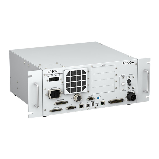
Page 26: Part Names And Functions
A protective filter is installed in front of the fan to filter out dust. Check the condition of the filter regularly and clean it when necessary. A dirty filter may result in malfunction of the robot system due to temperature rise of the Controller. RC700 / RC700-A Rev.23... - Page 27 Connects Teach Pendant TP1, TP2, TP3 (Option) and TP bypass plug. Note that the shape of the TP port differs between RC700 and RC700-A. For details, refer to Setup & Operation 8. TP Port. Do not connect the following to the TP port of RC700/RC700-A. It may result in NOTE ...
- Page 28 Safety 2. Part Names and Functions (15) R-I/O connector This connector is for the input signals used for the real time I/O function. (16) RC700: DU OUT connector / RC700-A: OUT connecter The connector for Drive Unit. (17) Development PC connection USB port This port connects the Controller and the Development PC using a USB cable.
- Page 29 (3) Set the screw removed in the step (1) to the lockout bracket B so as not to lose it. (4) Put a padlock through the holes of the lockout brackets A and B to lock. Padlock RC700 / RC700-A Rev.23...
-
Page 30: Led And Seven-Segment Led
PAUSE Blink line number *1 For error numbers, refer to EPSON RC+ 7.0 SPEL+ Language Reference, or Online Help. *2 In initial status, execution line of task number 1 is displayed in three-digit. Use Ton statement to change the displayed task number. -
Page 31: Particular Status Display
Refer to Maintenance 4. Backup and Restore. AC power supply drop is detected and software shut down. Software shut down is specified from the EPSON RC+ 7.0 (software) or the Teach Pendant (option). *1 When the Initialize Error occurs, reboot the Controller. If the Initialize Error is displayed again after the Controller is rebooted, please contact the supplier of your region. -
Page 32: Safety Features
Overload Detection The dynamic brake circuit is activated when the system detects the overload status of the motor. Irregular Torque (out-of-control manipulator) Detection The dynamic brake circuit is activated when irregular motor torque (motor output) is detected. RC700 / RC700-A Rev.23... - Page 33 AC Power Supply Voltage Drop Detection The dynamic brake circuit is activated when the drop of the power supply voltage is detected. Temperature Anomaly Detection The temperature anomaly is detected. Fan Malfunction Detection Malfunction of the fan rotation speed is detected. RC700 / RC700-A Rev.23...
-
Page 34: Installation
1 kV or les (Signal wire) Electrostatic noise 4 kV or less Base table Use a base table that is at least 100 mm off the floor. Placing the Controller directly on the floor could allow dust penetration leading to malfunction. RC700 / RC700-A Rev.23... -
Page 35: Installation
(C) Rack Mounting * A plate for rack mounting is required. * The rubber foot needs to be replaced. For Controller installation to the Controller box or the base table, process screw holes as NOTE follows. RC700 / RC700-A Rev.23... -
Page 36: Wall Mounting Option
(Figure/Picture: RC700) Wall mounting with the front side down Wall mounting with the front side up Controller outer dimensions when using the wall mounting option Dimensions of the mounting holes for the wall (Unit: mm) RC700 / RC700-A Rev.23... - Page 37 The LED/7 segment board has the ferrite code (Reference: Maintenance 7.8.2 DMB-LED Board (RC700-A)) If the LED DISPLAY PLATE is installed with “wall mounting with the front side up” described in the step (7) below, the cable which passes the ferrite core will be an opposite direction.
- Page 38 Wall mounting with the front side down Wall mounting with the front side up Front side Front side Front side Front side NOTE Be careful not to pull the cable. RC700 / RC700-A Rev.23...
- Page 39 The rubber foot may be needed when the installation type is changed. Please keep the rubber foot for future use. (13) Mount the Controller to the wall. (Mounting screw×8 M5 × 8 mm or longer) Tightening torque 80 to 110 N·cm RC700 / RC700-A Rev.23...
-
Page 40: Power Supply
10 kHz or more leakage current. If you install a circuit breaker, please select one that will handle the above mentioned “peak current”. The power receptacle shall be installed near the equipment and shall be easily accessible. RC700 / RC700-A Rev.23... -
Page 41: Ac Power Cable
Make sure to insert the plug of the AC power cable firmly when connecting to the Controller. Item Specification Black, Black AC power wire (2 cables) or Black, White Ground wire Green / Yellow Cable length Terminal M4 round solderless terminal RC700 / RC700-A Rev.23... -
Page 42: Cable Connection
Manipulator may cause not only improper function of the robot system but also safety problems. CAUTION ■ Before connecting the connector, make sure that the pins are not bent. Connecting with the pins bent may damage the connector and result in malfunction of the robot system. RC700 / RC700-A Rev.23... -
Page 43: Typical Cable Connection
(7) LAN (Ethernet Communication) (8) I/O Connector Input/Output Device (9) TP Connector Teach Pendant (10) Standard RS-232C Connector FieldBus I/O Expansion I/O RS-232C Option PG board Analog I/O EUROMAP67 Force Sensor I/F Board (11) R-I/O Connector Input/Output Device RC700 / RC700-A Rev.23... - Page 44 For details, refer to Setup & Operation 10. Standard RS-232C Port. (11) R-I/O Connector This connector is used for connecting with input signals necessary for real time I/O function. For details, refer to the Setup & Operation 13. R-I/O Connector. RC700 / RC700-A Rev.23...
-
Page 45: Connecting Manipulator To Controller
Therefore the Controller should be connected to the Manipulator whose serial number is specified in the Connection Check label attached on the front of the Controller. The Manipulator’s serial number is indicated on the signature label on the back of the NOTE Manipulator. RC700 / RC700-A Rev.23... -
Page 46: Noise Countermeasures
The spark suppressor is more effective when placed closer to the motor. - As they are easily influenced by noise, keep cable such as USB, Ethernet, RS-232C, or fieldbus away from peripheral noise sources. RC700 / RC700-A Rev.23... -
Page 47: Operation Mode (Teach/Auto/Test)
In this mode, the specified Function can be executed with multi-task / single-task, multi-manipulator / single-manipulator at high speed. NOTE T2 mode cannot be used on RC700-A Controllers complying with the UL standards. RC700 / RC700-A Rev.23... -
Page 48: Switch Operation Mode
For details on how to release latch, refer to Setup & Operation 9.1 Safety Door Switch and Latch Release Switch NOTE T2 mode cannot be used on RC700-A Controllers complying with the UL standards. RC700 / RC700-A Rev.23... -
Page 49: Program Mode (Auto)
Follow the procedures below to switch to the Program mode. 4.3.2 Setup from EPSON RC+ Switch the mode to Program mode from the EPSON RC+. (1) Select EPSON RC+ menu-[Setup]-[System Configuration] to display the [System Configuration] dialog. (2) Select [Startup]-[Start mode]. -
Page 50: Auto Mode (Auto)
Auto mode (AUTO) is for automatic operation of the Robot system. Procedures for switching to the Auto mode (AUTO) are the followings. A : Set the start mode of the EPSON RC+ to “Auto” and start the EPSON RC+. (Refer to Setup & Operation 4.4.2 Setup from EPSON RC+.) B : Offline the EPSON RC+. -
Page 51: Setup From Control Device
Safety 4. Operation Mode (TEACH/AUTO/TEST) 4.4.3 Setup from Control Device Set the control device from EPSON RC+. (1) Select EPSON RC+ menu-[Setup]-[System Configuration] to display the [System Configuration] dialog. (2) Select [Controller]-[Configuration]. (3) Select [Setup Controller]-[Control Device] to select the control device from the following two types. -
Page 52: Development Pc Connection Usb Port
Development PC connection USB port (USB B series connector) Development PC connection USB Port (Figure: RC700) For other details of development PC and Controller connection, refer to EPSON RC+ 7.0 NOTE User’s Guide 5.12.1 PC to Controller Communications Command. -
Page 53: Pc And Controller Connection Using Development Pc Connection Usb Port
Development PC Connection USB Port Connection of the development PC and the Controller is indicated. (1) Make sure that software EPSON RC+ 7.0 is installed to the Controller connected to the development PC. (Install the software when it is not installed.) (2) Connect the development PC and the Controller using a USB cable. -
Page 54: Disconnection Of Development Pc And Controller
5.4 Disconnection of Development PC and Controller This section describes how to disconnect the development PC and the Controller communication. (1) Select the EPSON RC+ 7.0 menu-[Setup]-[PC to Controller Communications] to display the [PC to Controller Communications] dialog. (2) Click the <Disconnect> button. -
Page 55: Memory Port
This function saves various kinds of Controller data to the USB memory with one push. Data saved in the USB memory is loaded to EPSON RC+ 7.0 to get the status of the Controller and the program simply and accurately. -
Page 56: Backup Controller Function
USB memory or execute the storage during Motor OFF status. 6.3.2 Load Data with EPSON RC+ 7.0 The procedure to read the data stored in the USB memory by EPSON RC+ 7.0 and display the Controller status is described in the following manual. -
Page 57: Details Of Data
NOTE Delete files that do not relate to the project before transfer. This function is used to send the data to the system director and EPSON from the end users for problem analysis. 6.4 Details of Data The following data files are created by the Controller backup function. -
Page 58: Lan (Ethernet Communication) Port
Setup & Operation 7. LAN (Ethernet Communication) Port 7. LAN (Ethernet Communication) Port - Refer to EPSON RC+ 7.0 User’s Guide 5.12.1 PC to Controller Communications NOTE Command (Setup Menu) for other details for the development PC and Controller connection. -
Page 59: Changing Controller Ip Address
Setup & Operation 5. Development PC Connection USB Port (2) Select the EPSON RC+ 7.0 menu-[Setup]-[Controller] to display the following dialog. (3) Select [Controller]-[Configuration]. (4) Enter the proper IP address and subnet mask and click the <Apply> button. -
Page 60: Connection Of Development Pc And Controller With Ethernet
(1) Connect the development PC and the Controller using the Ethernet cable. (2) Turn on the Controller. (3) Start EPSON RC+ 7.0. (4) Display the [PC to Controller Communication] dialog from [Setup] in EPSON RC+ 7.0 menu. (5) Click the <Add> button. -
Page 61: Disconnection Of Development Pc And Controller With Ethernet
<Close> button to close the [PC to Controller Communications] dialog. Connection between the development PC and the Controller is complete. Now the robot system can be used via an Ethernet connection from EPSON RC+ 7.0. 7.5 Disconnection of Development PC and Controller with Ethernet Disconnection of the development PC and the Controller is shown below. -
Page 62: Tp Port
When the Teach Pendant is not connected, connect the TP bypass plug. Do not connect the following devices to the TP port of / RC700-A. Connecting these devices may result in malfunction of the device since the pin assignments are different. -
Page 63: Teach Pendant Connection
Setup & Operation 8. TP Port 8.2 Teach Pendant Connection A cable for connection to the RC700 / RC700-A Controller is attached to the Teach Pendant. Connect this cable connector to the TP/OP port. Communication is set automatically. Enable the Teach Pendant by one of the following procedures. -
Page 64: Emergency
Emergency Stop switch. Be sure to use these input terminals to keep the system safe. Connector Standard EMERGENCY connector D-sub 25 male pin (Controller side) Mounting style #4 - 40 * The E-STOP BOX, connector cable, terminal block, and EMERGENCY EMERGENCY connector kit are offered as options. RC700 / RC700-A Rev.23... -
Page 65: Safety Door Switch
When the latched TEACH mode is released while the safety door is open, the status of NOTE Manipulator power is operation-prohibited because the safety door is open at that time. To execute a Manipulator operation, close the safety door again, and then close the latch release input. RC700 / RC700-A Rev.23... -
Page 66: Checking Latch Release Switch Operation
The latch release input also functions to acknowledge the change of to TEACH mode. NOTE In order to change the latched condition of TEACH mode, turn the mode selector key switch on the Teach Pendant to “Auto”. Then, close the latch release input. RC700 / RC700-A Rev.23... -
Page 67: Emergency Stop Switch Connection
To recover from the emergency stop condition, follow the procedure of safety check as required by the system. After safety check, the operations below are required to recover from the emergency stop condition. - Release the Emergency Stop Switch - Execute the RESET command RC700 / RC700-A Rev.23... -
Page 68: Pin Assignments
The 24 V output is for emergency stop. Do not use it for other purposes. Doing so may result in system malfunction. Do not apply reverse voltage to the Emergency Stop circuit. Doing so may CAUTION result in system malfunction. RC700 / RC700-A Rev.23... -
Page 69: Circuit Diagrams
ESTOP1− AC Input ESTOP2− Emergency Stop detection External +24V Safety Door input 1 Safety Door input 2 Latch release input External +24V Latch release input Close :Latch off NOTE:+24V GND Open :Latch on + 5V GND RC700 / RC700-A Rev.23... -
Page 70: Example 2: External Safety Relay Typical Application
AC Input Emergency Stop detection External +24V External +24V Safety Door input 1 Safety Door input 2 Latch Release input External +24V Latch release input Close :Latch off NOTE:+24V GND Open :Latch on + 5V GND RC700 / RC700-A Rev.23... -
Page 71: Standard Rs-232C Port
When an RS-232C board is mounted in as option unit, the Controller software automatically identifies the RS-232C board. Therefore, no software configuration is needed. Correct identification can be confirmed from EPSON RC+ 7.0. (1) Select the EPSON RC+ 7.0 menu-[Setup]-[System Configuration] to display the [System Configuration] dialog. Select the [RS232]-[CU]. -
Page 72: Rs-232C Software Communication Setup (Rs-232C)
Odd, even, NA Terminator CR, LF, CRLF Refer to EPSON RC+ 7.0 Online Help or Users Guide – 13. RS-232C Communications for RS-232C communication from the Robot application. 10.4 Communication Cable (RS-232C) Prepare a communication cable as described in this section. -
Page 73: I/O Connector
: +10.8 V (min.) OFF Voltage : +5 V (max.) Input Current : 10 mA (TYP) at +24 V input Two types of wiring are available for use with the two-way photo coupler in the input circuit. RC700 / RC700-A Rev.23... - Page 74 4 Input No.2 (Same) 5 Input No.3 (Same) 6 Input No.4 (Same) 7 Input No.5 (Same) 8 Input No.6 (Same) 9 Input No.7 (Same) 18 Input No.8 to 15 common 19 Input No.8 (Same) 20 Input No.9 Omit RC700 / RC700-A Rev.23...
- Page 75 4 Input No.2 (Same) 5 Input No.3 (Same) 6 Input No.4 (Same) 7 Input No.5 (Same) 8 Input No.6 (Same) 9 Input No.7 (Same) 18 Input No.8 to 15 common (Same) 19 Input No.8 20 Input No.9 Omit RC700 / RC700-A Rev.23...
-
Page 76: Output Circuit
(Same) 15 Output No.5 (Same) 27 Output No.6 (Same) 28 Output No.7 17 Output No.0 to 7 common (GND) (Same) 29 Output No.8 (Same) 30 Output No.9 (Same) Omit 33 Output No.8 to 15 common (GND) RC700 / RC700-A Rev.23... - Page 77 (Same) 15 Output No.5 (Same) 27 Output No.6 (Same) 28 Output No.7 17 Output No.0 to 7 common (+DC) (Same) 29 Output No.8 (Same) 30 Output No.9 (Same) Omit 33 Output No.8 to 15 common (+DC) RC700 / RC700-A Rev.23...
-
Page 78: Pin Assignments
12. I/O Remote Settings. Connector Standard D-sub 50 male pin I/O Connector (Controller side) Mounting style #4 - 40 * The I/O connector, I/O cable, and terminal block are offered as options. * I/O connector is included with shipment. RC700 / RC700-A Rev.23... -
Page 79: I/O Remote Settings
The user defines the I/O number that a remote function is assigned to using software configuration. For details about communication with external equipment, refer to EPSON RC+ 7.0 User’s Guide – 12. Remote Control. ■ When using remote I/O, always make sure of the followings. Using the robot system under unsatisfactory conditions may cause malfunction of the system and/or safety problems. -
Page 80: I/O Signal Description
Remote function is initially assigned to both input and output from 0 to 7. To change the function assignment from the initial setting, use EPSON RC+ 7.0. To use all signals, you will need to add Expansion I/O or Fieldbus I/O board(s). - Page 81 Same signal as the input will be output to ALIVE output. ALIVE Not Set The master equipment can perform alive monitoring of the controller by switching the input periodically and checking the output signal. RC700 / RC700-A Rev.23...
- Page 82 For details, refer to EPSON RC+ 7.0 Online Help or Motor in SPEL+ Language Reference. (*7) For details, refer to EPSON RC+ 7.0 Online Help or MCal in SPEL+ Language Reference. (*8) This is for experienced users only. Make sure that you fully understand the input specification before using.
- Page 83 Preferences (1): “Motor power low when ForcePowerLow signal OFF” Preferences (2): “ForcePowerLow signal change pauses all tasks” For details of the controller preferences, refer to EPSON RC+ 7.0 User’s Guide [Setup]-[System Configuration]-[Controller]-[Preferences] in 5.12.2 [System Configuration] Command (Setup Menu).
-
Page 84: Remote Output Signals
Turns ON when the robot is in the approach check area. Not set (*3) InsideBox15 InsidePlane1 Turns ON when the robot is in the approach check plane. Not set (*4) InsidePlane15 Alarm Turns ON when any of the alarms is occurring. (*9) Not set RC700 / RC700-A Rev.23... - Page 85 Output signal for alive monitoring of the controller. The signal input by ALIVE input will be output. The master ALIVE Not set equipment can perform alive monitoring of the controller by switching the input periodically and checking the output signal. RC700 / RC700-A Rev.23...
- Page 86 - The setting is Auto mode and the control device is remote. - The setting is Program mode and Remote I/O is enabled. (*3) For details, refer to EPSON RC+ 7.0 Online Help or Box in SPEL Language Reference. (*4) For details, refer to EPSON RC+ 7.0 Online Help or Plane in SPEL Language Reference.
-
Page 87: Timing Specifications
* Paused Output SelProg1 Input Start Input Pause Input Continue Input Stop Input * The duration varies depending on the Quick Pause (QP) setting and the program’s operating status at the time of Pause input [Unit: msec] RC700 / RC700-A Rev.23... -
Page 88: Timing Diagram For Safety Door Input Sequence
1052 Output Paused 1052 Output SafeguardOn Output MotorsOn Output Safety Input Latch Input Continue Input [Unit: msec] 12.2.5 Timing Diagram for Emergency Stop Sequence Running Output MotorsOn Output EStopOn Output Emergency Input Reset Input [Unit: msec] RC700 / RC700-A Rev.23... -
Page 89: R-I/O Connector
If you use this function with Vision, you can create an application of parts pickup, alignment, and assembly by robots without stopping. For details, refer to EPSON RC+7.0 Users Guide – 19. Real time I/O. 13.1 Input Circuit Input Voltage Range : +24 V ±10%... -
Page 90: Pin Assignments
- Use a shielded cable and route the cables as far from the surrounding noise sources as possible. CAUTION For details, refer to Setup & Operation: 3.5 Noise Countermeasures. - Make sure to check the cable routing before turning on the power supply. RC700 / RC700-A Rev.23... -
Page 91: Option Slots
14. Option Slots 14.1 About Option Slots Use the Option Slot to install the optional boards of RC700 / RC700-A Controller. Up to four option boards can be installed in the controller. The types of the option boards are as follows: 14.2 Expansion I/O Board... -
Page 92: Expansion I/O Board
DSW1 DSW2 14.2.3 Confirmation with EPSON RC+ 7.0 (Expansion I/O Board) When an expansion I/O board is mounted to the option unit, the Controller software automatically identifies the expansion I/O board. Therefore, no software configuration is needed. Correct identification can be confirmed from EPSON RC+ 7.0. -
Page 93: Input Circuit
Setup & Operation 14. Option Slots (1) Select the EPSON RC+ 7.0 menu-[Setup]-[System Configuration] to display the [System Configuration] dialog. (2) Select [Controller]-[Inputs / Outputs]. (3) Make sure that “Yes” is displayed in the Installed column. The expansion I/O board is identified by the Controller software. Corresponding Input and Output is available. - Page 94 4 Input No.66 (Same) 5 Input No.67 (Same) 6 Input No.68 (Same) 7 Input No.69 (Same) 8 Input No.70 (Same) 9 Input No.71 (Same) 18 Input No.72 to 79 common (Same) 19 Input No.72 20 Input No.73 Omit RC700 / RC700-A Rev.23...
-
Page 95: Output Circuit
■ Be sure to wire the output circuit properly because it has no protection circuitry for short-circuit and reverse-connection. Improper wiring may cause malfunction of the parts on the board and then improper function of the robot system. RC700 / RC700-A Rev.23... - Page 96 13 Output No.67 (Same) 14 Output No.68 (Same) 15 Output No.69 (Same) 27 Output No.70 (Same) 28 Output No.71 (Same) 17 Output No.64 to 71 Common (GND) 29 Output No.72 30 Output No.73 ~ ~ ~ ~ Omit RC700 / RC700-A Rev.23...
- Page 97 13 Output No.67 (Same) 14 Output No.68 (Same) 15 Output No.69 (Same) 27 Output No.70 (Same) 28 Output No.71 (Same) 33 Output No.72 to 79 Common 29 Output No.72 30 Output No.73 ~ ~ ~ Omit ~ RC700 / RC700-A Rev.23...
-
Page 98: Pin Assignments (Expansion I/O Board)
Output common No.64 to 71 Not Used Connector Standard D-sub 50 male pin I/O Connector (Controller side) Mounting style #4 - 40 * The I/O connector, I/O connector cable, terminal block, and I/O connector kit are offered as options. RC700 / RC700-A Rev.23... - Page 99 Output common No.96 to Not Used Connector Standard D-sub 50 male pin I/O Connector (Controller side) Mounting style #4 - 40 * The I/O connector, I/O connector cable, terminal block, and I/O connector kit are offered as options. RC700 / RC700-A Rev.23...
- Page 100 Output common No.128 to Not Used Connector Standard D-sub 50 male pin I/O Connector (Controller side) Mounting style #4 - 40 * The I/O connector, I/O connector cable, terminal block, and I/O connector kit are offered as options. RC700 / RC700-A Rev.23...
- Page 101 Output common No.160 to Not Used Connector Standard D-sub 50 male pin I/O Connector (Controller side) Mounting style #4 - 40 * The I/O connector, I/O connector cable, terminal block, and I/O connector kit are offered as options. RC700 / RC700-A Rev.23...
-
Page 102: Fieldbus I/O Board
14.3 Fieldbus I/O Board The Fieldbus I/O board has the following six types. - DeviceNet - PROFIBUS-DP - PROFINET - CC-LINK - EtherNet/IP - EtherCAT For the details, refer to the Robot Controller RC700/RC90 Controller Option Fieldbus I/O manual. RC700 / RC700-A Rev.23... -
Page 103: Rs-232C Board
Board Appearance Switch and Jumper Configuration Set DSW1, DSW2 and JMP1. CN3 is all open. board board (#2 or #4) JMP1 IRQ5 IRQ5 IRQ7 IRQ7 (#3 or #5) IRQ10 IRQ10 DSW1 IRQ11 IRQ11 DSW2 IRQ15 IRQ15 RC700 / RC700-A Rev.23... -
Page 104: Confirmation With Epson Rc+ (Rs-232C)
7, 8 Stop bit length 1, 2 Parity Odd, even, NA Terminator CR, LF, CRLF Refer to EPSON RC+ 7.0 Online Help or Users Guide – 13. RS-232C Communications for RS-232C communication from the Robot application. RC700 / RC700-A Rev.23... -
Page 105: Communication Cable (Rs-232C)
Pin No Signal Function Signal Direction Data carrier detect Input Receive data Input Send data Output Terminal ready Output Signal ground Data set ready Input Request to send Output Clear to send Input Ring indicator Input RC700 / RC700-A Rev.23... -
Page 106: Pg Board
The PG board has the following two types of usage. For details, refer to the related manuals. When using as the conveyor encoder: Refer to EPSON RC+ 7.0 User’s Guide 16. Conveyor Tracking When using as a PG motion system: Refer to Robot Controller RC700/RC90 option PG Motion System... -
Page 107: Analog I/O Board
Analog I/O Board 4CH PC for MC Power Manipulator (Optional Board) Development ADC CH2 DAC CH2 ADC CH1 DAC CH1 External equipment 1 * External equipment 2 * External equipment 3 * External equipment 4 * *: Voltage/Current Input RC700 / RC700-A Rev.23... -
Page 108: Board Configuration (Analog I/O Board)
Setup & Operation 14. Option Slots Overview of Analog I/O Board Circuit Rv: Voltage Input Terminating Resistance (100kΩ), Rc: Current Input Terminating Resistance 14.6.2 Board Configuration (Analog I/O Board) RC700 / RC700-A Rev.23... - Page 109 Voltage ±10V output mode 0~5V DAC 2ch Not Use Not Use Not Use Not Use Not Use 0~10V * 0~20mA Current output mode 4~20mA *: Default: DAC default configuration (voltage output: 0 to 10V) SWD1 SWD2 RC700 / RC700-A Rev.23...
- Page 110 Input Mode 0 to 5.12V ADC 2ch 0 to 10.24V * Current 0 to 24mA Input Mode SWD4: Not used. Please turn them OFF. *: Default: ADC default configuration (voltage input: 0 to 10.24V) SWD1 SWD3 SWD4 RC700 / RC700-A Rev.23...
-
Page 111: Confirmation With Epson Rc+ (Analog I/O Board)
I/O board to the optional unit of the controller. Therefore, no software configuration is needed. Correct identification can be confirmed from EPSON RC+. Select the EPSON RC+ 7.0 menu-[Setup]-[System Configuration] to display the [System Configuration] dialog. (2) Select [Controller]-[Inputs / Outputs]-[Analog I/O]. RC700 / RC700-A Rev.23... -
Page 112: Input Circuit (Analog I/O Board)
Applying a voltage more than ±11V may result in malfunction of the board. Improper wiring or short circuit may cause malfunction of the parts on the board and then improper function of the robot system. RC700 / RC700-A Rev.23... -
Page 113: Pin Assignments (Analog I/O Board)
COM (DAC 2ch) IOUT (DAC 2ch) Shield (DAC 2ch) COM (DAC 2ch) Not Used Not Used Not Used Not Used Not Used Not Used Not Used Not Used VIN (ADC 2ch) Shield (ADC 2ch) COM (ADC 2ch) RC700 / RC700-A Rev.23... -
Page 114: Force Sensor I/F Board
14.7.2 Board Configuration (Force Sensor I/F Board) Board Appearance Switch and Jumper Configuration Do not change the following DSW1, DSW2, and JMP1 configurations. IRQ5 (Sensor1) IRQ7 IRQ10 JMP1 IRQ11 IRQ15 DSW1 DSW2 CN3 is all open. RC700 / RC700-A Rev.23... -
Page 115: Confirmation With Epson Rc+ (Force Sensor I/F Board)
Force Sensor I/F board to the optional slot of the controller. Correct identification can be confirmed from EPSON RC+. Select the EPSON RC+ 7.0 menu-[Setup]-[System Configuration] to display the [System Configuration] dialog. (2) Select [Force Sensing]-[Force Sensor I/F Unit]. -
Page 116: Euromap67 Board
The connector signal placement is described below. Setup & Operation 14.8.11 Emergency stop connecter Pin Assignments List of connectors used Connecter No. Manufacturer Model DD-50PF-N 10126-3000PE, 10326-52K0-008 CN3 (accessory) 10136-3000PE, 10336-52K0-008 T1319320125-000 / T2020252201-000 / Tyco T2020252101-000 RC700 / RC700-A Rev.23... - Page 117 Setup & Operation 14. Option Slots Connection outline (IMM: Injection Molding Machine) One EUROMAP67 board: Two EUROMAP67 boards: RC700 / RC700-A Rev.23...
-
Page 118: Notes On The Euromap67 Board
Not fixed by EUROMAP, manufacturer I/O Input (*1) dependent Supply from handling device / robot 0V (Robot → IMM) Emergency stop of robot channel1 Emergency stop of robot channel2 Mold area free Reserved for future use by EUROMAP RC700 / RC700-A Rev.23... - Page 119 Reserved for future use by EUROMAP I/O Input (*1) Not fixed by EUROMAP, manufacturer I/O Input (*1) dependent Supply from IMM 0V (IMM → Robot) *1: DO NOT input a voltage which exceeds 24V. Board may get damage and burnout. RC700 / RC700-A Rev.23...
-
Page 120: Board Settings (Euromap67 Board)
(5) Use four screws to fix the EUROMAP67 board in place. First, temporarily fasten the four screws in place. Next, fully tighten screws located diagonally opposite each other. Take care not to damage the thread holes when doing so. RC700 / RC700-A Rev.23... - Page 121 Use a cross-point screwdriver to fasten the connector (CN2). (7) Refer to the following to connect CN3 to the emergency stop switch (emergency stop, safety door, latch). Setup & Operation 9. EMERGENCY (8) Connect “CN3”. Use a cross-point screwdriver to fasten the connector (CN3). RC700 / RC700-A Rev.23...
- Page 122 (10) Mount the Top Panel. (Mounting screw ×6) (11) Connect “Cable2 CN4” to the IMM. (12) Connect the power plug. Turn ON the Controller and make sure that the Controller starts properly without any vibration or abnormal noise. RC700 / RC700-A Rev.23...
-
Page 123: Confirming With Epson Rc+ 7.0 (Euromap67 Board)
You can check whether the software has correctly recognized the EUROMAP67 board on the EPSON RC+ 7.0 screen. (1) Select EPSON RC+ 7.0 menu - [Setup] - [System Configuration] to display the [System Configuration] dialog box. (2) Select [Controller] - [Input/Output]. -
Page 124: Circuit Overview (Euromap67 Board)
Setup & Operation 14. Option Slots 14.8.6 Circuit Overview (EUROMAP67 Board) EUROMAP67 Board: System diagram RC700 / RC700-A Rev.23... -
Page 125: Input Circuit (Euromap67 Board)
Doing so may damage board parts and prevent the robot system from functioning properly. Note that the I/O logic for controlling the IMM will vary depending on the molding machine. Confirm the proper logic to use before creating programs. RC700 / RC700-A Rev.23... -
Page 126: Emergency Stop, Safeguard (Euromap67 Board)
When the safety door has been opened on the IMM side: A function is used to communicate the open safeguard instruction to the robot controller. EUROMAP67 Board: Overview of Emergency stop circuit EUROMAP67 Board: Overview of Safety Door circuit RC700 / RC700-A Rev.23... -
Page 127: I/O Pin Assignments (Euromap67 Board)
21/20 ZA2/ZC2 Safety1 (IMM) ZA3/ZC3 Safety2 (IMM) 23/22 ZA4/ZC4 24V (Robot) GND (Robot) Emergency1 (Robot) 35/34 A1/C1 Emergency2 (Robot) 19/18 A2/C2 *1: DO NOT input a voltage which exceeds 24V. Board may get damage and burnout. RC700 / RC700-A Rev.23... - Page 128 21/20 ZA2/ZC2 Safety1 (IMM) ZA3/ZC3 Safety2 (IMM) 23/22 ZA4/ZC4 24V (Robot) GND (Robot) Emergency1 (Robot) 35/34 A1/C1 Emergency2 (Robot) 19/18 A2/C2 *1: DO NOT input a voltage which exceeds 24V. Board may get damage and burnout. RC700 / RC700-A Rev.23...
-
Page 129: Emergency Stop Connecter Pin Assignments
19 SDLATCH2 Safety Door Latch Release 20 SD21 Safety Door input 2 21 SD22 Safety Door input 2 22 24V 24V output 23 24V 24V output 24 24VGND 24VGND output 25 24VGND 24VGND output 26 Not Used RC700 / RC700-A Rev.23... - Page 130 25 24VGND 24VGND output 26 Not Used 27 Not Used 28 Not Used 29 Not Used 30 Not Used 31 Not Used 32 Not Used 33 Not Used 34 Not Used 35 Not Used 36 Not Used RC700 / RC700-A Rev.23...
- Page 131 Maintenance This section contains maintenance procedures for the Robot Controller.
-
Page 133: Safety Precautions On Maintenance
■ Do not shock, shake, or drop any parts during maintenance. When the parts CAUTION related with data are shocked physically, they may be damaged and may also cause data loss during data loading/saving. RC700 / RC700-A Rev.23... - Page 134 Manipulator may cause not only improper function of the robot system but also serious safety problems. Before performing maintenance on the Controller, all the data must be copied as a backup. NOTE The details of data backup/restore are described in the Maintenance 4. Backup and Restore. RC700 / RC700-A Rev.23...
-
Page 135: Regular Maintenance Inspection
Duration 5 minutes 5 minutes 20 minutes 15 minutes 5 minutes (reference) 7.2.1 7.2.2 Fan Filter Fan Filter Front Fan Regenerative Battery Reference: Fan (RC700-A Maintenance only) Expected 30,000 hours 30,000 hours product life RC700 / RC700-A Rev.23... -
Page 136: Controller Structure
MDB : Motor Drive Board DMB : Drive Main Board DPB : Drive Power Board DMB-LED Board Battery Fan1 DMB-SUB Board (Front Fan) * MDB3 is not supplied for G1, G3, G6, G10, G20, and RS. RC700 / RC700-A Rev.23... -
Page 137: Diagram Of Cable Connections
Maintenance 3. Controller Structure 3.2 Diagram of Cable Connections 3.2.1 RC700 RC700 / RC700-A Rev.23... -
Page 138: Rc700-A
C4, C8, G1, G3, G6, G10, G20, RS, X5 (Motor Driver (5, 6 axis) is not supplied for G1, G3, G6, G10, G20, RS and X5.) N2, N6 (Combinations of axes for motor drivers differ from other manipulators.) RC700 / RC700-A Rev.23... -
Page 139: Backup And Restore
For some problems, backup may not be available before maintenance has to be performed. Be sure to backup the data after making changes, before problems occur. “Controller status storage function” is one of the RC700 / RC700-A functions. It saves NOTE ... -
Page 140: Backup
Maintenance 4. Backup and Restore 4.3 Backup Backup the Controller status from the EPSON RC+ 7.0. (1) Select EPSON RC+ 7.0 menu-[Tools]-[Controller] to display the [Controller Tools] dialog. (2) Click the <Backup Controller…> button to display the [Browse For Folder] dialog. -
Page 141: Restore
■ Do not edit the backup files. Otherwise, operation of the robot system after data CAUTION restoration to the Controller is not assured. (1) Select the EPSON RC+ 7.0 menu-[Tools]-[Controller] to display the [Controller Tools] dialog. (2) Click the <Restore Controller…> button to display the [Browse For Folder] dialog. - Page 142 The default is unchecked. When a project is restored, the values of Global Preserve variables are loaded. For details about Global Preserve variable backup, refer to EPSON RC+ 7.0 User’s Guide 5.10.10 Display Variables Command (Run Menu). Vision hardware configuration This checkbox allows you to restore the vision hardware configuration.
- Page 143 When restoring the backup which includes the data of the robot configured to the Drive NOTE Unit, be sure to restore the data while the Drive Unit is connected and turned on. When restoring the backup including unsupported robot information to the target NOTE controller, an error occurs. RC700 / RC700-A Rev.23...
-
Page 144: Firmware Update
Controller firmware is supplied by CD-ROM as needed. Please contact the supplier of your region for information. You must use a PC running EPSON RC+ 7.0 connected to a Controller with USB to update the Controller firmware. Firmware cannot be updated with an Ethernet connection. - Page 145 (8) The firmware upgrade starts. It takes several minutes to complete. Do not disconnect the USB cable during transfer or turn OFF the Controller or the NOTE development PC. (9) Continuous data file transfer starts. RC700 / RC700-A Rev.23...
- Page 146 The firmware upgrade is complete. When you install the firmware (Ver.7.4.0.2 or later) on the controller which the firmware NOTE (before Ver.7.4.0.2) has been installed, the following message is displayed. When the message is displayed, re-install the firmware. RC700 / RC700-A Rev.23...
-
Page 147: Controller Recovery
Controller to start in Recovery mode. (3) Make sure that the LED of ERROR, TEACH, and PROGRAM are lighting. (4) Follow the procedure in Maintenance 5.4 Firmware Initialization Procedure from step (3) to initialize the firmware. RC700 / RC700-A Rev.23... -
Page 148: Firmware Initialization Procedure
(1) Connect the development PC to the Controller with a USB cable (the firmware cannot be changed with an Ethernet connection). (2) Turn ON the Controller. Do not start the development software EPSON RC+ 7.0 until firmware initialization is complete. - Page 149 (9) The following dialog appears after the Controller reboot. Click the <Finish> button. The firmware upgrade is completed. Start EPSON RC+ 7.0 and restore the Controller settings. For details of restoring the operating system, refer to Maintenance 4. Backup and Restore.
-
Page 150: Alarm
- Robot battery replacement - Grease up Ver.7.2.0.x or later - Replacement of the timing belt - Replacement of the motor - Replacement of the reduction gear unit - Replacement of the ball screw spline unit RC700 / RC700-A Rev.23... -
Page 151: Before Controller Firmware Ver.7.1.8.X
When the robot is deleted from the configuration, the alarm will also be automatically deleted. For details on the robot configuration, refer to the EPSON RC+ 7.0 User’s Guide 10.1 Setting the Robot Model. Changing of the robot should be done carefully. The alarm setting will be reset ... -
Page 152: How To View The Alarm Information
Maintenance 6. Alarm 6.1.1.2 Controller Battery The controller battery is automatically configured at the first connection with the EPSON RC+7.0 after upgrading to the firmware version 7.1.0.x and later. If you are using the controller before the version upgrade, there may be a difference in the NOTE ... -
Page 153: How To Edit The Alarm Information
6.1.4 Alarm Notifying Method The alarm notifying method needs to be configured by the output bit of the Remote I/O. The Remote I/O can be configured in the EPSON RC+ 7.0- [Setup] - [System Configuration] - [Controller] - [Remote Control]. -
Page 154: How To Cancel The Alarm
By referring to Maintenance 6.1.3 How to Edit the Alarm, change the alarm information in the same steps. 6.1.5.2 Remote Input The alarm can be canceled by the input bit of the Remote I/O. For details, refer to the EPSON RC+ 7.0 User’s Guide 12.1 Remote I/O. RC700 / RC700-A Rev.23... -
Page 155: Controller Firmware Ver.7.2.0.X Or Later
Initial installation : Maintenance is enabled. Upgrade : Maintenance inherits the previous data. (Disables as default) For details for enabling or disabling the maintenance, refer to the EPSON RC+ 7.0 User’s Guide 5.12.2 [System Configuration] Command (Setup Menu) - [Setup]-[System Configuration]-[Controller]-[Preferences] Page NOTE ... -
Page 156: How To View The Maintenance Information
6.2.1.2 Controller Maintenance Information If the maintenance is enabled, the controller battery is automatically configured at the first connection with the EPSON RC+7.0 after upgrading to the firmware version 7.2.0.x and later. If you are using the controller before the version upgrade, there may be a difference in the NOTE ... - Page 157 Remaining months is calculated based on the past operation conditions. Enable to set the period for calculation by “HealthCalcPeriod” command. (Default: seven days of the controller ON time) Remaining months may not be calculated properly until the period for the calculation passed. RC700 / RC700-A Rev.23...
-
Page 158: How To Edit The Maintenance Information
Maintenance 6. Alarm 6.2.3 How to Edit the Maintenance Information The configured maintenance information can be edited in the EPSON RC+ 7.0 Ver.7.2.x or later. (1) Select the EPSON RC+ 7.0 menu-[Tools]-[Maintenance] to display the [Controller Tools] dialog box. (2) To edit the maintenance information, display the [Maintenance] dialog box. -
Page 159: Alarm Notifying Method
Maintenance 9.1 Error Code Table The alarm notifying method can be configured by the output bit of the Remote I/O. The Remote I/O can be configured in the EPSON RC+ 7.0- [Setup] - [System Configuration] - [Controller] - [Remote Control]. -
Page 160: Maintenance Parts Replacement Procedures
(1) Set the fan filter to the fan filter cover. Installation (2) Mount the fan filter cover with the screw. (3) Connect the power plug. Turn ON the Controller and make sure that the Controller starts properly without any vibration or abnormal noise. RC700 / RC700-A Rev.23... -
Page 161: Fan
(4) Connect the power plug. Turn ON the Controller and make sure that the Controller starts properly without any vibration or abnormal noise. * Pay attention to the right and wrong sides of the fan when installing it. RC700 / RC700-A Rev.23... -
Page 162: Regenerative Fan (Rc700-A Only)
Maintenance 7. Maintenance Parts Replacement Procedures 7.2.2 Regenerative Fan (RC700-A only) The regenerative fan is installed only in RC700-A. Regenerative Fan (1) Turn OFF the Controller. removal (2) Disconnect the power plug. (RC700-A only) (3) Remove the Top Cover. (Mounting screw ×6) (4) Remove the cable tie binding the 15 V power supply cable and fan cable. - Page 163 (9) Connect the power plug. Turn ON the Controller and make sure that the Controller starts properly without any vibration or abnormal noise. * Pay attention to the right and wrong sides of the fan when installing it. RC700 / RC700-A Rev.23...
-
Page 164: Battery
・Soldering the terminal of the lithium battery directly ・Forced Discharge CAUTION ■ Be sure to use the battery supplied as maintenance part from EPSON (Refer to 10. Maintenance Parts List). ■ When disposing of the battery, consult with the professional disposal services or comply with the local regulation. - Page 165 (3) Insert the battery bracket and secure it with the screws. (Mounting screw ×2) (4) Connect the power plug. Turn ON the Controller and make sure that the Controller starts properly without any vibration or abnormal noise. RC700 / RC700-A Rev.23...
-
Page 166: Cf (Compact Flash)
(3) Connect the connector (CN39). (4) Mount the Top Panel. (Mounting screw ×6) (5) Connect the power plug. Turn ON the Controller and make sure that the Controller starts properly without any vibration or abnormal noise. RC700 / RC700-A Rev.23... -
Page 167: Mdb
Manipulator Joint #1, #2 Joint #3, #4 Remarks 10A/10A MDB type 2145517** Assy. No. 2157372** 15A/15A-2 10A/10A MDB type RC700-A 2166640** 2145517** Assy. No. 2171936** 2157372** 30A/30A 15A/15A-2 MDB type 2146123** 2166640** Assy. No. 2153723** 2171936** RC700 / RC700-A Rev.23... - Page 168 (7) Pull out the MDBs in the direction shown in the picture. NOTE When removing the MDBs, make sure to remember the position of each board. Install the boards to the same positions after replacement. (8) Remove the MDB clamp 3. (Mounting screw ×2) RC700 / RC700-A Rev.23...
- Page 169 MDB clamp 1 and on the connectors are the same. (6) Mount the Top Panel. (Mounting screw ×6) (7) Connect the power plug. Turn ON the Controller and make sure that the Controller starts properly without any vibration or abnormal noise. RC700 / RC700-A Rev.23...
-
Page 170: Dmb
(5) Remove the MDBs. Refer to Maintenance: 7.5 MDB. (6) Remove the DMB-OPTION board. (Mounting screw ×3) (7) Remove five screws on the side of the chassis. (8) Remove the fixing plate of the DMB-OPTION board. RC700 / RC700-A Rev.23... - Page 171 Maintenance 7. Maintenance Parts Replacement Procedures (9) RC700: Remove the five connectors from the DMB. RC700-A: Remove the twelve connectors from the DMB. (10) Remove the DMB mounting screws (×14). (11) Remove the fan. Refer to Maintenance: 7.2 Fan. (12) Remove the DMB from the chassis.
- Page 172 (4) Mount the fan. Refer to Maintenance: 7.2 Fan. (5) Tighten the DMB mounting screw (×14). (6) RC700: Connect the five connectors to the DMB. RC700-A: Connect the twelve connectors to the DMB. (7) Mount the fixing plate of the DMB-OPTION board.
- Page 173 R-I/O Connector DU OUT Connector (12) Mount the Top Panel. (Mounting screw ×6) (13) Connect the power plug. Turn ON the Controller and make sure that the Controller starts properly without any vibration or abnormal noise. RC700 / RC700-A Rev.23...
-
Page 174: Dmb-Sub Board
Refer to: Setup & Operation 2. Part Names and Functions (14) Encoder Voltage Adjustment Switch (6) Connect the power plug. Turn ON the Controller and make sure that the Controller starts properly without any vibration or abnormal noise. RC700 / RC700-A Rev.23... -
Page 175: Dmb-Led Board
Maintenance 7. Maintenance Parts Replacement Procedures 7.8 DMB-LED Board 7.8.1 DMB-LED Board (RC700) DMB-LED Board (1) Turn OFF the Controller. Removal (2) Disconnect the power plug. (RC700) (3) Remove the Top Panel. (Mounting screw ×6) (4) Disconnect the cables connected to the DMB-LED board. -
Page 176: Dmb-Led Board (Rc700-A)
Maintenance 7. Maintenance Parts Replacement Procedures 7.8.2 DMB-LED Board (RC700-A) (1) Turn OFF the Controller. DMB-LED Board Removal (2) Disconnect the power plug. (RC700-A) (3) Remove the Top Panel. (Mounting screw ×6) (4) Remove the DMB-LED board from the front panel. -
Page 177: Dpb
(6) Remove eight connectors from the DPB. (7) RC700-A only: Remove the regenerative fan extension connector. (8) RC700-A only: Remove the rear plate from the body. (Mounting screw ×5) (9) Remove the DPB mounting screws. (10) Remove the DPB from the chassis. RC700 / RC700-A Rev.23... - Page 178 (1) Insert the DPB to the chassis. Installation (2) Fix the DPB with screws. (3) RC700-A only: Mount the rear plate. (Mounting screw ×5) (4) RC700-A only: Connect the regenerative fan extension connector. (5) Connect the eight connectors to the DPB.
-
Page 179: Option Board
At this point, one screw for the Option Slot Panel is left unused. (8) Mount the Top Panel. (Mounting screws ×6) (9) After connecting the power plug, turn on the Controller and check it works normally without vibration and abnormal sound. RC700 / RC700-A Rev.23... -
Page 180: Verifying Robot System Operation
- No error is displayed. - There is servo excitation and the Manipulator operates normally. (4) Execute various motion commands (such as JUMP, etc.). The Manipulator must operate accordingly and normally without vibration or unusual sounds. RC700 / RC700-A Rev.23... -
Page 181: Troubleshooting
Termination due to low voltage of the power supply. Controller control program has Stores this log when the controller is completed. rebooted from EPSON RC+ or TP1. Preserve variables save area has been cleaned. Function Main started. Function Main started. Later same Skip the log "Function Main started."... - Page 182 Replace the timing belt. 1000 times 1000 The belt alarm occurred. Replace the After replacing the timing belts, reset times of belt and reset the alarm. the alarm in EPSON RC+ consumption boundary 7.0-[Tools]-[Controller]-[Maintenance]. rate value Grease up the ball screw spline.
- Page 183 Replace the ball screw spline. 1000 times 1000 The ball screw spline alarm occurred. After replacing the ball screw spline, times of Replace the ball screw spline and reset reset the alarm in EPSON RC+ consumption boundary the alarm. 7.0-[Tools]-[Controller]-[Maintenance]. rate value Replace the battery.
- Page 184 If normal voltage is not generated by 100 times of 100 times of brake, encoder and fan is lower than 24V of Drive Unit 2 power supply boundary current value the specified voltage. alone, replace the power supply. value RC700 / RC700-A Rev.23...
- Page 185 Replace the fan. value controller and the compact vision are rebooted, replace the system fan. Compact Vision chassis fan RPM has Replace the system fan of the compact Current Camera No. decreased. Replace the fan. vision. value RC700 / RC700-A Rev.23...
- Page 186 Clicking the same jog button will operate the robot in the PTO motion. Motor driver type does not match the current robot model. Check the robot Check the robot model. model. Replace the motor driver. RC700 / RC700-A Rev.23...
- Page 187 Reboot the controller. controller. Turn OFF the controller and replace the battery. Low voltage from the encoder battery. For the battery replacement Replace the battery. procedure, refer to Maintenance in the Manipulator manual. Servo alarm D. RC700 / RC700-A Rev.23...
- Page 188 1027 Cannot execute in Auto mode. Change to the Program mode. Cannot execute in Auto mode 1028 Change to the Program mode. except from the main console. 1029 Cannot execute from OP. Enable the OP input. RC700 / RC700-A Rev.23...
- Page 189 Export Controller Status failed. memory. 3. Retry after rebooting the controller. Execute the command after 1052 Export Controller Status busy. completing the controller status backup. Execution in Test mode is 1053 Execute in other modes. prohibited RC700 / RC700-A Rev.23...
- Page 190 1058 Switch to <Teach/T2> key. mode. T2 mode cannot be used on 1059 Cannot change to T2 mode. RC700-A Controllers complying with UL standards. 1. Reboot the controller. 1100 File failure. Cannot access the file. 2. Reinstall the firmware. 3. Replace the CF.
- Page 191 Restore the controller configuration. Failed to open the settings file. File failure. 1156 Restore the controller configuration. Failed to save the settings file. File failure. 1157 Restore the controller configuration. Failed to read the settings file. RC700 / RC700-A Rev.23...
- Page 192 This error occurs during compilation Compile failure. 1200 from TP. Correct where the error Check the compile message. occurred. This error occurs during compilation Link failure. 1201 from TP. Correct where the error Check the link message. occurred. RC700 / RC700-A Rev.23...
- Page 193 Force Guide sequence. sequence. Confirm Force Guide sequence. Confirm Force Guide sequence. Specified Force Guide object as Confirm the settings of Force Guide 1413 ConditionObject is disabled. object. Confirm the settings. Failed to convert program. 1420 Execute rebuild. RC700 / RC700-A Rev.23...
- Page 194 Failed to write Prg file. 1500 Communication error. Execute the command again after a while. Check the connection 1501 Command did not complete in time. between the EPSON RC+7.0 and controller. Communicati on timeout 2: USB cable Communication disconnection disconnection...
- Page 195 Transmission error. Rebuild the project. Parser communication failure. 1583 Reboot the controller. Initialization error. Parser communication failure. 1584 Reboot the controller. Connection error. Parser communication failure. Reboot the controller. 1585 Parameter is invalid. Rebuild the project. RC700 / RC700-A Rev.23...
- Page 196 Timeout during connection via 1806 Ethernet. Timeout during connection via 1807 USB. Failed to install EPSON RC+ 7.0. 1808 USB driver is not installed. Install EPSON RC+ 7.0 again. Initialization failure. 1809 Reboot the System. Failed to initialize PC daemon.
- Page 197 Message Remedy Note 1 Note 2 1863 The parameter is invalid. Initialization failure. Installation of the EPSON RC+ 7.0 1864 Virtual controller does not exist. failed. Reinstall the software. Initialization failure. 1. Retry after a while. 1865 Failed to start virtual controller.
- Page 198 Rebuild the project. because of improper code. Object file error. 2018 Build the project. Failed to Rebuild the project. calculate the variable size. Object file error. 2019 Cannot process the variable wait. Rebuild the project. Build the project. RC700 / RC700-A Rev.23...
- Page 199 Synchronize the files of the project. 2054 Function ID failure. Rebuild the Rebuild the project. project. Object file operation failure. Synchronize the files of the project. 2055 Local variable ID failure. Rebuild Rebuild the project. the project. RC700 / RC700-A Rev.23...
- Page 200 Reboot the controller. Failed to terminate MNG. Initialization failure. 2110 Reboot the controller. Failed to allocate memory. Initialization failure. 2111 Restore the controller configuration. Failed to initialize motion. Initialization failure. 2112 Reboot the controller. Failed to terminate motion. RC700 / RC700-A Rev.23...
- Page 201 2140 Cannot use drive units. Return the configuration file to original setting if it was changed. DU Initialization Error. Failed to Check the connection with drive 2141 initialize drive units. units. RC700 / RC700-A Rev.23...
- Page 202 2162 Not enough buffer to store the local Review the size of the Local variable. variable. Operation failure. 2163 Value change is available only Halt the task by the break point. when the task is halted. RC700 / RC700-A Rev.23...
- Page 203 Cannot calculate because it was 2190 Review the program. queue data. Cannot execute AbortMotion If you don’t operate the robot from a 2191 because robot is not running from a program, you cannot use task. AbortMotion. RC700 / RC700-A Rev.23...
- Page 204 15. Review the program. Specified Box is not defined. 2217 Box number is not defined. Review the Box number. Available Box numbers are from 1 to 2218 Plane number is out of range. 15. Review the program. RC700 / RC700-A Rev.23...
- Page 205 Dimensions of array do not match Check the array's dimensions. 2241 the declaration. Review the program. 2242 Zero '0' was used as a divisor. Review the program. RC700 / RC700-A Rev.23...
- Page 206 Output number is out of the The specified available range. The Port No. or For available output number, see the 2263 output the Device No. is out of the online help. Review the program. number available range. RC700 / RC700-A Rev.23...
- Page 207 Timeout period set by TMOut Investigate the cause of timeout. Timeout 2282 statement in WaitNet statement Check whether the set timeout period Port number period expired. is proper. Timeout. 2283 Reboot the controller. Timeout at display device setting. RC700 / RC700-A Rev.23...
- Page 208 Check whether all tasks are 2307 while tasks are executing. completed. Find the previously occurring error in Cannot turn on the motor because 2308 the error history and resolve its of a critical error. cause. Then, reboot the controller. RC700 / RC700-A Rev.23...
- Page 209 Cannot use the argument in Trap Check the program. Call or Xqt statement. Trap failure. 2331 Failed to process Trap Goto Rebuild the project. statement. Trap failure. 2332 Failed to process Trap Goto Rebuild the project. statement. RC700 / RC700-A Rev.23...
- Page 210 Specified command cannot be Execute specified command from the 2353 executed from the Command program. window. Cannot execute the I/O output Execute the I/O output command with 2354 command when the Enable Switch the enable switch gripped. is OFF. RC700 / RC700-A Rev.23...
- Page 211 Create a Curve file again. Curve failure. Reboot the controller. 2404 Failed to update the curve file. Create a Curve file again. Curve failure. Reboot the controller. 2405 Failed to read the curve file. Create a Curve file again. RC700 / RC700-A Rev.23...
- Page 212 File number is already used. File Error. Make sure the file exists and you 2441 Failed to open the file. specified the file correctly. File Error. 2442 Open the file in advance. The file is not open. RC700 / RC700-A Rev.23...
- Page 213 Review the program. Windows Communication Error. 2476 Reboot the Controller. Failed to wait for event. Windows Communication Error. Make sure the specified folder is 2477 Invalid folder. correct. Windows Communication Error. 2478 Rebuild the project. Invalid error code. RC700 / RC700-A Rev.23...
- Page 214 2519 Invalid format syntax for FmtStr$. Check the format. Check whether the specified point file 2520 File name is too long. name is correct. The maximum string length of the file name is 32. RC700 / RC700-A Rev.23...
- Page 215 Too many force files. Reboot the controller. 2548 Delete the force files or use the Initialize the controller firmware. existing force files. Replace the controller. RC700 / RC700-A Rev.23...
- Page 216 Execute it after the force guide guide sequence. sequence ends. An instruction that cannot be executed by parallel processing 2568 Review the program. was executed. Review the program. Cannot get the force guide 2569 Reboot the Controller. sequence property. RC700 / RC700-A Rev.23...
- Page 217 DU with the manipulator registered. Because the increase and The controller was rebooted due to decrease of the drive unit was 2846 change of connection with the Drive recognized, the controller unit is Unit. rebooted. RC700 / RC700-A Rev.23...
- Page 218 Please inquire with us if a similar force monitor. error occurs after rebooting it. Reboot the controller. Failed to allocate memory for the 2859 Please inquire with us if a similar force log. error occurs after rebooting it. RC700 / RC700-A Rev.23...
- Page 219 To start force monitor newly, quit the Force monitor cannot be launched 2872 running force monitor and start a new twice. one. RC700 / RC700-A Rev.23...
- Page 220 Check whether the Ethernet port. Ethernet cable is connected properly. Check whether the Ethernet port is Failed to open as client for the 2901 set properly. Check whether the Ethernet port. Ethernet cable is connected properly. RC700 / RC700-A Rev.23...
- Page 221 A single port cannot be used by more 2932 Port number another task. than one task. 2933 Failed to write to the RS-232C port. Check the communication. Port number RS-232C port connection not 2934 Check the RS-232C port. completed. RC700 / RC700-A Rev.23...
- Page 222 MNG failure. IntervalOutBit error. Reboot the Controller. 2984 MNG failure. CtrReset error. Reboot the Controller. If you use the simulator, check if the 2997 Collision Detection object is placed in the direction of the robot motion. RC700 / RC700-A Rev.23...
- Page 223 Maintenance 9. Troubleshooting Message Remedy Note 1 Note 2 AbortMotion attempted when robot 2998 See Help for AbortMotion. was not moving AbortMotion attempted when robot 2999 See Help for AbortMotion. was moving RC700 / RC700-A Rev.23...
- Page 224 Specify a single point for the point Cannot use a point expression in 3115 flag setting. Do not specify a point the first argument. expression. Array number of dimensions does Check the number of array 3116 not match the declaration. dimensions. RC700 / RC700-A Rev.23...
- Page 225 BGo, Go, TGo, Jump, Jump3, and 3131 Cannot specify ECP parameter. Arc statements. Correct the program. Arch parameter cannot be specified in BGo, Go, TGo, Arc, Arc3, BMove, 3132 Cannot specify Arch parameter. Move, and TMove statements. Correct the program RC700 / RC700-A Rev.23...
- Page 226 3143 available size. exceed the available length. For details of the available length, refer to EPSON RC+ User’s Guide “6.4 Function and Variable Names (Naming restriction)”. ' ** ' already used for a function Correct the identifier ' ** ' or the 3144 name.
- Page 227 Note 1 Note 2 Limit value of the array elements depends on the type of variables. Specified elements of the array Refer to EPSON RC+7.0 User’s 3152 variable are beyond the available Guide “6.7.6 Array” and correct the size. number of array elements so as not to exceed the limit value.
- Page 228 Array variables cannot be used 3190 waited by Wait statement. Correct with the Wait command. the program. Change of real variable cannot be Real variables cannot be used with 3191 waited by Wait statement. Correct the Wait command. the program. RC700 / RC700-A Rev.23...
- Page 229 On/Off was not specified. Brake, AutoLJM, SetSw, and Box statements. Specify On or Off. High or Low must be specified for the 3216 High/Low was not specified. power mode setting of Power statement. Specify High or Low. RC700 / RC700-A Rev.23...
- Page 230 Above/Below was not specified. is not specified in Elbow statement. Specify either Above or Below. Setting value for the hand orientation 3232 Righty/Lefty was not specified. is not specified in Hand statement. Specify either Righty or Lefty. RC700 / RC700-A Rev.23...
- Page 231 Language Reference “SetCom Statement” and specify a proper terminator. Hardware flow is not specified in SetCom statement. Refer to SPEL+ 3243 Hardware flow was not specified. Language Reference “SetCom Statement” and specify a proper flow control. RC700 / RC700-A Rev.23...
- Page 232 ByRef is 3255 ByRef was not specified. specified for calling. Specify the ByRef parameter. Variable type is not specified in 3256 Variable type was not specified. Global statement. Specify a proper variable type. RC700 / RC700-A Rev.23...
- Page 233 GSet and GGet 3269 was not specified. statements. Specify a property name or control name. Property name is not specified in 3270 Property Name was not specified. GSet and GGet statements. Specify a property name. RC700 / RC700-A Rev.23...
- Page 234 “SizeMode Property” and specify a proper setting value. StartPosition property setting value is not specified in GSet statement. 3280 StartPosition was not specified. Refer to GUI Builder 7.0 manual “StartPosition Property” and specify a proper setting value. RC700 / RC700-A Rev.23...
- Page 235 Type of the disk that is subject to file manipulation is not specified in ChDisk statement. Refer to SPEL+ 3293 Disk type was not specified. Language Reference “ChDisk Statement” and specify a proper disk type. RC700 / RC700-A Rev.23...
- Page 236 Correct the program (variable name). The same module variable name is 3310 Duplicate module variable. used for more than one file. Correct the program (variable name). 3311 File cannot be found. 3312 OBJ file is corrupt. RC700 / RC700-A Rev.23...
- Page 237 Wait command is beyond the the maximum allowed (64). Delete maximum allowed. the variables and rebuild the project. Call cannot be used in parallel Call cannot be used in parallel 3335 processing. Correct the program processing. and rebuild the project. RC700 / RC700-A Rev.23...
- Page 238 Send/receive data must be specified by Byte type array. The number of dimensions is not Single array variable was not proper in the command where single 3408 specified. array variable is only available. Correct the number of dimensions. RC700 / RC700-A Rev.23...
- Page 239 (negative logic) or 1 (positive logic). R-I/O input port number where the trigger input is connected is not specified in SetLatch statement. 3417 Port number is not specified. Refer to SPEL+ Language Reference “SetLatch Statement” and specify a proper port number. RC700 / RC700-A Rev.23...
- Page 240 “AvoidSingularity Statement” and specify a proper mode. Setting number of acceleration is not specified in AccelR function. Refer Acceleration value was not 3427 to SPEL+ Language Reference specified. “AccelR Function” and specify a proper setting value. RC700 / RC700-A Rev.23...
- Page 241 Force property name or status is not specified in FSet, FGet, MPSet, name is not specified. 3450 and MPGet statements. Add a property name or a status Add a property name or a status name. name. RC700 / RC700-A Rev.23...
- Page 242 Specify a valid Force Trigger object 3465 Specify a Force Trigger Object or or label. label. Mass Property Object or label is not specified. Specify a valid Mass Property object 3466 Specify a Mass Property Object or or label. label. RC700 / RC700-A Rev.23...
- Page 243 Specify a proper setting value. setting value is not specified in FSet statement. Specify a proper setting value. Another macro with the same name Duplicate macro in #define 3500 has been defined. Change the statement. macro name. RC700 / RC700-A Rev.23...
- Page 244 Wait statement. statements. Delete the PerformMode parameter. LJM parameter cannot be specified in The specified motion command BGo, TGo, Arc, Arc3, BMove, Move, 3605 cannot use PerformMode and TMove statements. Delete the parameter. LJM parameter. RC700 / RC700-A Rev.23...
- Page 245 LogIn function cannot be executed Specified function cannot be from the command window even 3806 executed from the Command when used with Print statement. window. Use the function in the program. RC700 / RC700-A Rev.23...
- Page 246 Functions for condition expression of the user defined remote output are Specified function cannot be used limited. Refer to EPSON RC+7.0 3812 with a Remote User Output. User’s Guide “11.8 User-defined Remote Output I/O” and specify a valid function.
- Page 247 Go, BGo, TGo, Jump, Jump3. Delete the CF parameter. Delete the CF parameter. Mass property object label cannot be Cannot specify Mass Property specified in MPDel, and MPList 3879 Object label. statements. Review the program. Correct the program. RC700 / RC700-A Rev.23...
- Page 248 Cannot enter the file name in the 3911 file name buffer. Cannot obtain the internal buffer. 3912 Cannot set priority. 3913 Reboot the controller. Rebuild the project. 3914 Invalid ICode. Rebuild the project. 3915 Invalid ICode. Rebuild the project. 3916 Invalid ICode. RC700 / RC700-A Rev.23...
- Page 249 3962 Neither Robot nor Object were 3963 specified. Invalid Object was specified. 3964 Invalid Object index was specified. 3965 Analog I/O TCPSpeed Type is not Specify a numerical value for 3990 specified. AIO_Set command 3rd parameter. RC700 / RC700-A Rev.23...
- Page 250 Point coordinate data used to Match the coordinate data for the 4022 define the Local is invalid. points to be specified. Cannot execute when the motor is Turn the motor power ON and then 4023 in the off state. execute. RC700 / RC700-A Rev.23...
- Page 251 Specified command is not Remove the unsupported command 4043 supported for this robot model or from the program. this joint type. Curve failure. Specified curve Create a Curve file again with the 4044 form is not supported. Curve statement. RC700 / RC700-A Rev.23...
- Page 252 On the specified point line by the Curve statement, set the orientation Orientation variation of adjacent 4063 variation of U, V, and W coordinate point is over 90 degrees. values between two adjacent points to under 90 degrees. RC700 / RC700-A Rev.23...
- Page 253 Turn the Enable Switch ON and then 4080 Switch is OFF. execute. Check the PG board. Check the connection with the motor Error was detected during 4081 driver. operation. Replace the PG board. Replace the controller. RC700 / RC700-A Rev.23...
- Page 254 Initialize the controller firmware. the current point or pulse. Replace the controller. Communication error in the motion Reboot the controller. 4101 control module. Cannot calculate Initialize the controller firmware. the current point or pulse. Replace the controller. RC700 / RC700-A Rev.23...
- Page 255 Reboot the controller. 4189 Communication error with the Initialize the controller firmware. module: VSRCMC. Replace the controller. Robot initialization failure. Reboot the controller. 4191 Physical-logical pulse Initialize the controller firmware. transformation matrix is invalid. Replace the controller. RC700 / RC700-A Rev.23...
- Page 256 Check the wiring. Low voltage of the main circuit power supply is detected. Check Check the power supply voltage, or 4224 the power supply voltage. reboot the controller. Reboot the controller. RC700 / RC700-A Rev.23...
- Page 257 A interruption error was detected in the controller. Irregular motion control Check the short-circuit and improper 4240 interruption was detected. connection of the peripheral Interruption duplicate. equipment wiring. (Emergency, D-I/O, and Expansion I/O connectors) Replace the controller. RC700 / RC700-A Rev.23...
- Page 258 Do not execute Stop or Pause. were carried out The robot cannot pass the elbow singularity area. The robot cannot pass Singularity 4257 To pass the elbow singularity area, Area of Elbow use SING_AVOID of “AvoidSingularity”. RC700 / RC700-A Rev.23...
- Page 259 For a CP motion command, the manipulator reached to the target Specified J6Flag is not reached. 4274 point with J6Flag which differs from Change J6Flag for target point. the one specified for the target point. Change J6Flag for the target point. RC700 / RC700-A Rev.23...
- Page 260 Continue operation cannot be Tracking motion cannot be continued 4403 done in tracking motion. after aborted/paused? Review the queue number. Or, The specified conveyor queue 4404 check whether the queue is data does not exist. registered. RC700 / RC700-A Rev.23...
- Page 261 Device is in use. device Note 1: Type of the device. Check whether the device is used in 4501 1: Analog Check whether other commands other task or command. I/O input are using the device. channel RC700 / RC700-A Rev.23...
- Page 262 Check whether the coordinates near the singularity is specified. Check whether the robot moves Approached the singularity point. 4604 closer to the singularity during the Avoid the singularity point. operation. Review the installation position of the robot. RC700 / RC700-A Rev.23...
- Page 263 Replace the DMB. connection or the robot setting. For T series, reboot the controller, take the measure against noise, and replace the motor unit. Encoder division setting failure. 5005 Check the model setting. Check the robot setting. RC700 / RC700-A Rev.23...
- Page 264 Current control circuit WDT failure. Replace the DMB. 5013 Reboot the controller. Check the Check the noise controller. countermeasures. For T series, reboot the controller, take the measure against noise, and replace the motor unit. RC700 / RC700-A Rev.23...
- Page 265 Replace the resolver board. Disconnection of the resolver Check the signal wiring of the excitation signal. Reset the manipulator (loose pin, 5026 encoder. Check the resolver board disconnection, short). or the robot internal wiring. Replace the resolver board. RC700 / RC700-A Rev.23...
- Page 266 (Missing pin, disconnection, short-circuit) Check the power supply voltage. (Low power supply voltage) Replace the motor driver. Replace the DMB. Replace the motor. For T series, replace the CPU board and motor unit in addition to the above. RC700 / RC700-A Rev.23...
- Page 267 (Missing pin, disconnection, short-circuit) Check the power supply voltage. (Low power supply voltage) Replace the motor driver. Replace the DMB. Replace the motor. For T series, replace the CPU board and motor unit in addition to the above. RC700 / RC700-A Rev.23...
- Page 268 (Missing pin, disconnection, short-circuit) Check the power supply voltage. (Low power supply voltage) Replace the motor driver. Replace the DMB. Replace the motor. For T series, replace the CPU board and motor unit in addition to the above. RC700 / RC700-A Rev.23...
- Page 269 (Missing pin, disconnection, short-circuit) Check the power supply voltage. (Low power supply voltage) Replace the motor driver. Replace the DMB. Replace the motor. For T series, replace the CPU board and motor unit in addition to the above. RC700 / RC700-A Rev.23...
- Page 270 Check the work motion speed torque control. range. Check the 15V power supply and 15V PWM drive power supply cable connection. 5051 failure. Reboot the controller. Replace the motor driver. Replace the 15V power supply. Replace the DMB. RC700 / RC700-A Rev.23...
- Page 271 Check the power supply voltage and correct them if necessary. If other error occurs at the same time, take a countermeasure for that first. Reference: EPSON RC+ 7.0 User’s Guide “6.18.10 Collision Detection Function (Error detection function of robot motion)” RC700 / RC700-A Rev.23...
- Page 272 Reboot the controller. Failed to initialize the force control. 5501 Initialize the controller firmware. Reboot the controller. Replace the controller. Reboot the controller. Force control calculation error. 5510 Initialize the controller firmware. Reboot the controller. Replace the controller. RC700 / RC700-A Rev.23...
- Page 273 Check the parameters. Force control is not supported for Check if the specified robot is this robot model. correct. 5536 Check the robot model and the Check if the Controller firmware controller firmware version. supports the robot model. RC700 / RC700-A Rev.23...
- Page 274 Reboot the Force Sensor and 5545 Execute the Reset property of the Force Sensor I/F unit (board). Force Sensor Object. Please inquire with us if a similar error occurs even after the above countermeasures are taken. RC700 / RC700-A Rev.23...
- Page 275 Check the configuration of the 5552 Check the configuration of the force force sensor. sensor. Unsupported function is executed Check the force sensor settings. 5553 on the connected force sensor. Review the program. Review the program. RC700 / RC700-A Rev.23...
- Page 276 AccelR, LimitSpeed and Check the parameter. LimitAccel. Enabled properties of the Force Enable the “Enabled” property for 5813 Control Object are all false. at least one axis. Set true to 1 or more axis. RC700 / RC700-A Rev.23...
- Page 277 Check the duration. Force control cannot resume from 5830 the pause. Abort the motion Abort the motion. command. Cannot execute this command Abort force control. 5831 during force control. Execute FCEnd command. Exit force control by FCEnd. RC700 / RC700-A Rev.23...
- Page 278 Specified force data cannot be updated nor deleted by FSet, Specified force data can't be 5909 updated. FDel, MPSet, or MPDel statement. Specified force data value is out of Specify the value within the 5910 allowable range. range. RC700 / RC700-A Rev.23...
- Page 279 Specified force file cannot be 5933 found. Specify a valid force file name. Specify a valid force file name. Make an enough space to write 5934 Cannot save the force file. Robot number the force file. RC700 / RC700-A Rev.23...
- Page 280 Cannot load the force file 5943 Update the controller firmware. because it is a newer version. Cannot load the force file Failed to read the force file. 5944 because the format is not Re-create the force file. supported. RC700 / RC700-A Rev.23...
- Page 281 Disable Windows Firewall. process failed (-201) Vision process Invalid Blob property 6533 Set a value in the valid range. ThresholdLow value (-11004) Vision process Invalid Blob property 6534 Set a value in the valid range. ThresholdHigh value (-11005) RC700 / RC700-A Rev.23...
- Page 282 Set a value in the valid range. Timeout value (-11525) Vision process Invalid Geom property 6575 Set a value in the valid range. RejectByArea value (-11526) Vision process Invalid Geom property 6576 Set a value in the valid range. SearchReversed value (-11527) RC700 / RC700-A Rev.23...
- Page 283 Set a value in the valid range. ContrastVariation value (-12511) Vision process Invalid Edge property 6641 Set a value in the valid range. StrengthTarget value (-12512) Vision process Invalid Edge property 6642 Set a value in the valid range. StrengthVariation value (12513) RC700 / RC700-A Rev.23...
- Page 284 Set Invalid quiet zone (-1011) the quiet zone narrower. Vision process Code Reader 6655 Change the code. Message is too long (-1012) Vision process OCR 6686 Delete the registered characters. Recognition dictionary is full (-2132) RC700 / RC700-A Rev.23...
- Page 285 Point area is allocated beyond the There are too many points. 7028 available point number. Review the number of points. Specified point file name is not 7029 correct. Specify a valid point file Check the file extension. name. RC700 / RC700-A Rev.23...
- Page 286 Re-create the point file. The point file format version is The point file is not supported. 7044 unsupported. Re-create the point file. The specified work queue number Check the specified work queue 7045 is invalid. number. RC700 / RC700-A Rev.23...
- Page 287 The fieldbus is broken or the controller software is damaged. Restore the controller firmware. The PLC is not running or not connected. Check the PLC, the communication cable, and peripherals. (If Code 1 is 22 when the CC-Link board is used.) RC700 / RC700-A Rev.23...
- Page 288 Check the port number to close. 7254 The specified port is not open. Check the port number to open. Check the port timeout period and 7255 Timeout reading from the port. update to the appropriate setting. RC700 / RC700-A Rev.23...
- Page 289 7261 Invalid function. Check the function definition to call. 7262 Invalid parameters. Check the function definition to call. Cannot execute while creating 7263 DLL. 7264 Failed to create DLL. 7265 DLL file cannot be found. RC700 / RC700-A Rev.23...
- Page 290 7346 Cannot execute a Vision statement program. from the command window. Matrix determinate too small. If specifying the virtual camera, 7400 specify the real camera. Invalid value for maximum motion 7402 Specify the valid value. distance. RC700 / RC700-A Rev.23...
- Page 291 7424 Cannot load the calibration points. Perform calibration point teach again. Invalid camera orientation. Check the CameraOrientation of 7425 calibration. Distortion correction calibration is Perform distortion correction if it is 7426 incomplete. set. RC700 / RC700-A Rev.23...
- Page 292 Window out of bounds. Set the window within the bounds. 7521 OCR font is invalid. Register the OCR font. Change the calibration name. The specified vision calibration 7522 Delete the existing calibration in already exists. advance. RC700 / RC700-A Rev.23...
- Page 293 Check the wiring of the camera. Invalid Radius. Radius must be 7549 >= RadiusInner and <= Correct the property value. RadiusOuter. 7550 OCR character does not exist. Register the OCR character. 7551 OCR option is not active. Enable the option. RC700 / RC700-A Rev.23...
- Page 294 Calibration generates points move Make the search area bigger or the 7598 distance too small. target smaller. Calibration generate points camera If specifying the virtual camera, 7599 to robot relation error. specify the real camera. RC700 / RC700-A Rev.23...
- Page 295 Permission denied. authority. Security. 7703 Register the options. Option not active. Source and destination cannot be the 7710 Specify another destination. same. Point file name is used by another 7711 Check the point file name. robot. RC700 / RC700-A Rev.23...
- Page 296 Check if the definition file exists. definition file. Simulator. Failed to copy the layout 7766 Reboot RC+. objects. Simulator. Failed to cut the layout 7767 Reboot RC+. objects. Simulator. Failed to paste the layout 7768 Reboot RC+. objects. RC700 / RC700-A Rev.23...
- Page 297 Restore the controller configuration. Failed to save the MCD file. MCD failure. 7808 Restore the controller configuration. Failed to create the MCD file. MCD failure. 7809 Restore the controller configuration. Failed to write the MCD file. RC700 / RC700-A Rev.23...
- Page 298 Replace the fieldbus master board. Check that the fieldbus master board is installed. 7904 Fieldbus invalid board. Reboot the computer where the fieldbus master board is installed. Replace the fieldbus master board. 7905 Fieldbus connection denied. RC700 / RC700-A Rev.23...
- Page 299 Force sensing. Sensor read failed. Force sensing. Sensor initialization 7953 failed. 7954 Force sensing. Sensor not initialized. Force sensing. Force or torque 7955 exceeded saturation level. 7975 Force Guide. Value out of range. 7976 Force Guide. Invalid property value. RC700 / RC700-A Rev.23...
- Page 300 Check whether the filter is not clogged up. Speed of the controller fan is Check whether the filter of the Boundary 9015 below the specified speed. controller is not clogged up. Current value value (FAN1) Replace the fan. RC700 / RC700-A Rev.23...
- Page 301 (FAN1) Replace the fan. DU2 Rotating speed of the Check whether the filter of the 9036 controller fan is below the Drive Unit 2 is not clogged up. allowed speed. (FAN2) Replace the fan. RC700 / RC700-A Rev.23...
- Page 302 Check the noise 9610 the controller. countermeasures. Check for noise. Replace Replace the DMB. the controller. Servo CPU internal RAM Check the noise failure. Reboot the 9611 countermeasures. controller. Check for noise. Replace the DMB. Replace the DMB. RC700 / RC700-A Rev.23...
- Page 303 Reboot the controller. Check countermeasures. for noise. Replace the DMB. Replace the DMB. Failure of the redundant Check the noise circuitry for the emergency 9623 countermeasures. stop or the safeguard. Replace the DMB. Check the wiring. RC700 / RC700-A Rev.23...
- Page 304 Sensor I/F board and Force Sensor I/F board. Sensor. 9697 Check connection of the Reboot the controller. Force Sensor I/F board and Please inquire with us if a similar Force Sensor. error occurs even after the above countermeasures are taken. RC700 / RC700-A Rev.23...
- Page 305 Replace the DMB. 9703 Check the signal cable For T series, reboot the controller, connection and the robot take the measure against noise, setting. and replace the CPU board and motor unit. RC700 / RC700-A Rev.23...
- Page 306 Servo CPU watchdog timer countermeasures. failure. For T series, check the connection 9712 Reboot the controller. Check of the signal cable. Reboot the the motor or the DMB. controller, take the measure against noise, and replace the motor unit. RC700 / RC700-A Rev.23...
- Page 307 G sensor communication Check the signal wiring of the failure. Check the signal cable manipulator (loose pin, 9723 connection or the robot disconnection, short). internal wiring. Check the noise countermeasure. Replace the control board. Replace the DMB. RC700 / RC700-A Rev.23...
- Page 308 OFF. Reset the Replace the motor. encoder. Reset the encoder. Replace the Speed is too high. Reset the motor. 9731 encoder. For T series, reboot the controller and replace the motor unit. 9732 Servo alarm A. RC700 / RC700-A Rev.23...
- Page 309 Install the RC+7.0 to another 10504 reserved for the RC620 Controller and computer. cannot be used for RC+7.0. The specified connection does not 10505 Check the connection number. exist. 10600 Frame grabber driver not installed. Install the driver. RC700 / RC700-A Rev.23...
-
Page 310: Cannot Connect The Development Pc And The Controller Using The Usb Cable
Click the <Cancel> button to close the [Add New Hardware] wizard. - If the following error message appears when connecting the development PC and Controller with the USB cable and connecting the Controller to EPSON RC+ 7.0, Windows may not recognize the Controller properly. Refer to Maintenance 9.2.1 Confirmation Using Windows Device Manager to check the connection of the Controller. -
Page 311: Confirmation Using Windows Device Manager
PC and the Controller must be connected with the USB cable. (2) Click Windows-[Control Panel]-<Performance and Maintenance>. (3) The [Performance and Maintenance] dialog appears. Click the <System> icon. (4) The [System Properties] dialog appears. Select the [Hardware] tab and click the <Device Manager> button. RC700 / RC700-A Rev.23... - Page 312 !! Error: 1805, Connection failure, check the controller startup and connection of the communication cable.” If “EPSON Robot Controller RC170” is not located under “Universal Serial Bus controllers” but located under “Other devices” in step (5), refer to Maintenance 9.2.2 When recognized under “Other devices”...
-
Page 313: When Recognized Under "Other Devices" In Windows Device Manager
9.2.2 When recognized under “Other devices” in Windows Device Manager If “EPSON Robot Controller RC170” is recognized under “Other devices” in the Windows device manager as shown in the following dialog, delete “EPSON Robot Controller RC170” from the device manager and connect the USB cable again to correct the problem. -
Page 314: Maintenance Parts List
Joint #1, #2 Joint #3, #4 Remarks 10A/10A MDB type 2172039 Code R13N874011 Old Code 15A/15A-2 10A/10A MDB type 2168582 2172039 Code RC700-A R13N874011 Old Code − 30A/30A 15A/15A-2 MDB type 2171456 2168582 Code R13NZ90002 Old Code − RC700 / RC700-A Rev.23... - Page 315 Maintenance 10. Maintenance Parts List The code of the following parts differs depending on the Controller. Also, the code of RC700-A differs depending on the serial number (Note: R7********). If you need the parts, please confirm the Controller type and serial number before contact...
- Page 316 2194667 Emergency Stop cable For EUROMAP67 Board EUROMAP67 Cable2 2194668 − IMM Connection cable EUROMAP67 Emergency For EUROMAP67 Board Connector 2165789 − Soldering plug Plug EUROMAP67 Emergency For EUROMAP67 Board − 2194882 Connector Shell kit Shell RC700 / RC700-A Rev.23...
Need help?
Do you have a question about the RC700 and is the answer not in the manual?
Questions and answers